


OWNER’S OPERATING MANUAL
457mm VARIABLE SPEED SCROLL SAW
MODEL ESW1846
SPECIFICATIONS
Voltage ........................................................... 240V 50Hz
Power Input ..............................................................180 W
No Load Speed ............................................600-1450 min
Blade Stroke .......................................................... 20 mm
Max. Cutting Thickness ......................................... 52 mm
Max. Cutting Capacity ......................................... 457 mm
Blade Length ........................................................127 mm
Net Weight .............................................................22.5 kg
Gross Weight ............................................................25 kg
THANK YOU FOR BUYING A RYOBI SCROLL SAW
Your new Scroll Saw has been engineered and manufactured to Ryobi's high standard for dependability, ease of operation and
operator safety. Properly cared for, it will give you years of rugged, trouble-free performance.
CAUTION: Carefully read through this entire owner's manual before using your
!
Pay close attention to the Rules for Safe Operation, Warnings, and Cautions.
If you use your Scroll Saw properly and only for what it is intended, you will enjoy years of safe, reliable service.
Thank You again for buying Ryobi tools.
Scroll Saw.
SAVE THIS MANUAL FOR FUTURE REFERENCE.
-1
N197

RULES FOR SAFE OPERATION
The purpose of safety rules is to attract your attention to
possible dangers. The safety symbols and the explanations
with them, require your careful attention and understanding.
The safety warnings do not by themselves eliminate any
danger. The instruction or warnings they give are not
substitutes for proper accident prevention measures.
SAFETY ALERT SYMBOL. Indicates caution
or warning. May be used in conjunction with
other symbols or pictures.
WARNING: Failure to obey a safety warning can
result in serious injury to yourself or to others.
Always follow the safety precautions to reduce
the risk of fire, electric shock and personal injury.
WARNING: Do not attempt to operate this tool
until you have read thoroughly and understood
completely, safety rules, etc. contained in this
manual. Failure to comply can result in
accidents involving fire, electric shock or serious
personal injury. Save owners manual and
review frequently for continuing safe operation
and instructing others who may use this tool.
The operation of any tool can
result in foreign objects being
thrown into your eyes, which can
result in severe eye damage.
Before beginning power tool
operation, always wear safety
goggles or safety glasses with side shields and a full
face shield when needed. We recommend Wide Vision
Safety Mask for use over eyeglasses or standard safety
glasses with side shields.
1.
KNOW YOUR POWER TOOL. Read owners manual
carefully. Learn its applications and limitations as well as
the specific potential hazards related to this tool.
GUARD AGAINST ELECTRICAL SHOCK BY
2.
PREVENTING BODY CONTACT WITH GROUNDED
SURFACES. For example, pipes, radiators, ranges,
refrigerator enclosures.
3.
KEEP WORK AREA CLEAN. Cluttered areas and
benches invite accidents.
4.
AVOID DANGEROUS ENVIRONMENT. Don't use power
tools in damp or wet locations or expose to rain. Keep
work area well lit.
5.
KEEP CHILDREN AND VISITORS AWAY. Visitors should
wear safety glasses and be kept a safe distance from
work area. Do not let visitors contact tool or extension
cord.
6. STORE IDLE TOOLS. When not in use, tools should be
stored in a dry and high or locked-up place, out of reach
of children.
7. DON'T FORCE TOOL. It will do the job better and safer
at the rate at which it was designed.
8. USE RIGHT TOOL. Don't force small tool or attachment
to do the job of a heavy duty tool. Don't use tool for
purpose not intended.
DRESS PROPERLY. Do not wear loose clothing or
9.
jewellery. They can be caught in moving parts. Rubber
gloves and non-skid footwear are recommended when
working outdoors. Also wear protective hair covering to
contain long hair.
10.
ALWAYS WEAR SAFETY GLASSES. Everyday
eyeglasses have only impact resistant lenses, they are
not safety glasses.
PROTECT YOUR LUNGS. Wear a dust mask if operation
11.
is dusty.
12.
PROTECT YOUR HEARING. Wear hearing protection
during extended periods of operation.
13. DON'T OVERREACH. Keep proper footing and balance
at all times. Do not use tool on a ladder or unstable
support. Secure tools when working at elevated levels.
14. MAINTAIN TOOLS WITH CARE. Keep tools sharp and
clean for better and safer performance. Follow
instructions for lubricating and changing accessories.
15. REMOVE ADJUSTING KEYS AND WRENCHES. Form
a habit of checking to see that keys and adjusting
wrenches are removed from tool before turning it on.
16.
NEVER USE IN AN EXPLOSIVE ATMOSPHERE.
Normal sparking of the motor could ignite fumes.
17. KEEP HANDLES DRY, CLEAN AND FREE FROM OIL
AND GREASE. Always use a clean cloth when cleaning.
Never use brake fluids, gasoline, petroleum based
products, or any strong solvents to clean your tool.
18.
18. STAY ALERT AND EXERCISE CONTROL. Watch what
you are doing and use common sense. Do not operate
tool when you are tired. Do not rush operation of tool.
19.
CHECK DAMAGED PARTS. Before further use of the
tool, a guard or any other part that is damaged should
be carefully checked to determine that it will operate
properly and perform its intended function. Check for
alignment of moving parts, binding of moving parts,
breakage of parts, mounting and any other conditions
that may affect its operation. A guard or any other part
that is damaged should be properly repaired or replaced
by an authorised service centre.
DO NOT USE TOOL IF SWITCH DOES NOT TURN IT
20.
ON AND OFF. Have defective switches replaced by
authorised service centre.
DO NOT OPERATE THIS TOOL WHILE UNDER THE
21.
INFLUENCE OF DRUGS, ALCOHOL OR ANY
MEDICATION.
THE APPLIANCE IS NOT INTENDED FOR USE BY
22.
YOUNG OR INFIRM PERSONS WITHOUT
SUPERVISION. YOUNG CHILDREN SHOULD BE
SUPERVISED TO ENSURE THAT THEY DO NOT PLAY
WITH THE APPLIANCE.
SAVE THESE INSTRUCTIONS
FOR FUTURE REFERENCE
Due to continued product
refinement policy, product features
and specifications can and will
change without notice. Check
current features and specifications
with your retailer.
Page 1
FEATURES
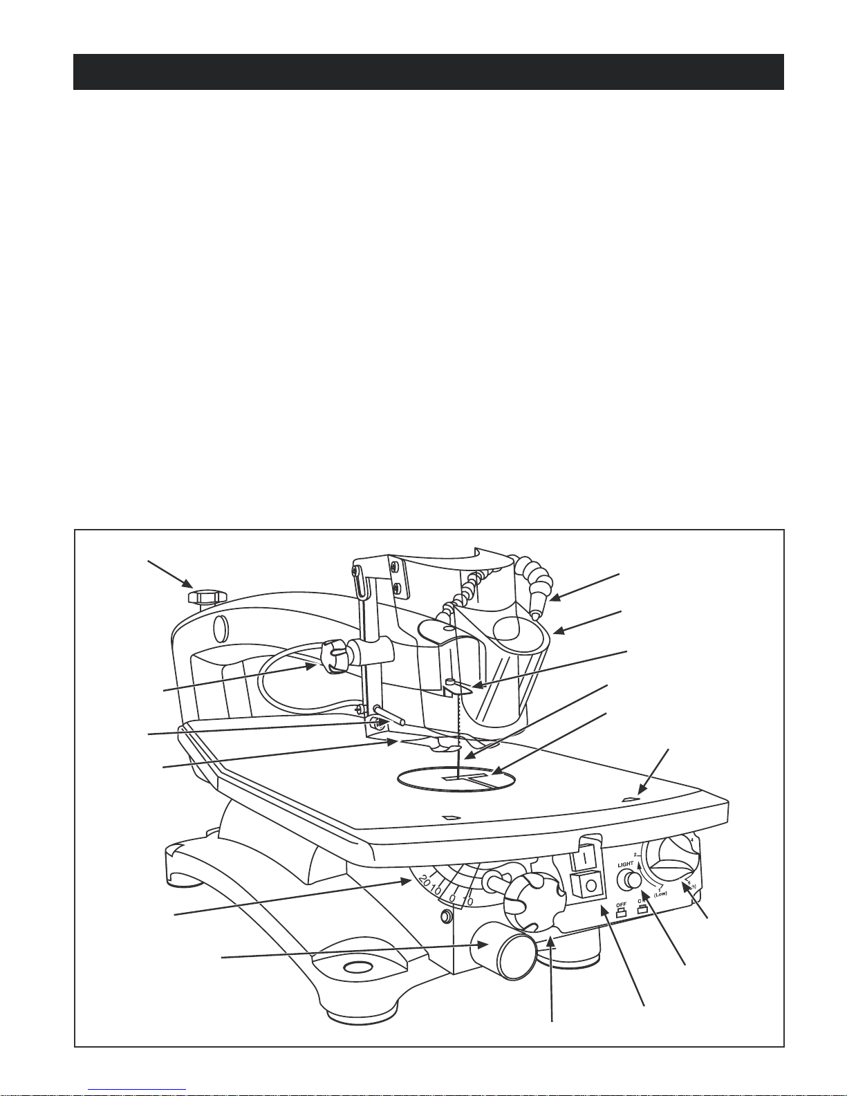
KNOW YOUR SCROLL SAW
Before attemping to use your saw, familiarize yourself with all
the operating features and safety requirements of your Ryobi
scroll saw. See Figure 1.
This versatile, variable speed scroll saw is great for making
toys, puzzles, games artwork, and jewelry. It is a handy doit-yourself tool. It cuts wood, wood composition products,
plastic, and other fibrous material up to 2 in. (52 mm) thick.
It aslso cuts nonferrous metals (aluminum, brass, copper).
1. Blade Tension Knob
Loosen or tighten the blade tension by turning the blade
tension knob.
2. Drop Foot Lock Knob
Allows you to raise or lower the drop foot and lock it in
place.
3. Sawdust Blower
Keeps the line of the cut on the workpiece clean for more
accurate scroll cuts. For best results, always direct air
flow at the blade and the workpiece.
4. Drop Foot
This foot should always be lowered until it just rests on
top of the workpiece to prevent the workpiece from lifting,
yet not so much that the workpiece drags.
5. Bevel Scale
The bevel scale and indicator show you the degree the
saw table is tilted.
6. Sawdust Exhaust
This feature will allow you to attach any 1-1/4 in. (32mm)
vacuum hose for easy sawdust collection.
7. LED (light)
Illuminates the work piece and blade for more accurate
cutting.
8. Combined Blade Guard
Have the function of magnifying glass.
9. Saw Blade
10. Saw Table with Throat Plate
Your scroll saw has an aluminum saw table with tilt control
for maximum accuracy. The throat plate, inserted in the
saw table, allows for blade clearance.
11. Blade Length Gauge
Used for attaching the blade adaptors at the proper length
for operation.
12. Variable Speed Knob
Turn the knob to adjust the speed from the high speed
of approximately 1450 SPM (storkes per minute) to the
low speed of approximately 600 SPM.
13. On/Off Switch for Light
14. Power On/Off Switch
15. Table Lock Knob
Allows you to tilt the table and lock it at the desired angle
up to 45º.
1. Blade tension
knob
2. Drop foot
lock knob
3. Sawdust
blower
4. Drop foot
5. Bevel scale
6. Sawdust exhaust
7. LED (light)
8. Combined Blade guard
Blade holder
9. Saw Blade
10. Throat plate
11. Blade length
guage
12. Variable
speed knob
13. Light on/off
switch
Page 2
15. Table lock knob
14. Power on/off switch
Fig. 1
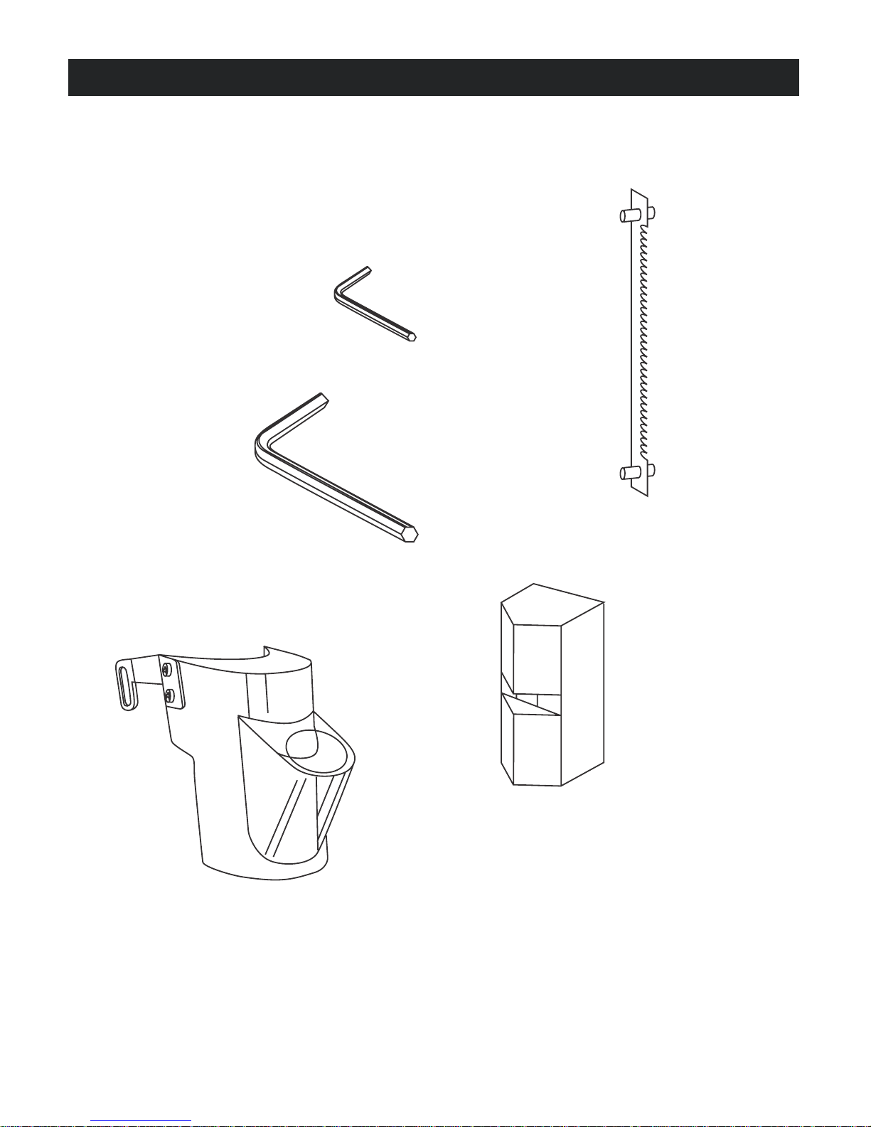
LOOSE PARTS
Check all loose parts from the box with the list below. Assemble according to the instructions on the following pages.
• 2.5 mm Hex Key
• 4 mm Hex Key
• Blade(s) (4 pcs)
• Combined Blade guard
• Blade adaptor (2 pcs)
2.5 mm Hex key
Blade
4 mm Hex key
Combined blade guard
Blade adaptor
Page 3
ASSEMBLY
MOUNTING SCROLL SAW TO WORKBENCH
WARNING:
To avoid serious personal injury from unexpected tool
movement, always securely mount scroll saw to a
workbench.
If the scroll saw is to be used in a permanent application, we
recommend that you secure it in a permanent location such
as a workbench. When mounting the saw to a workbench,
holes should be drilled through the supporting surface of the
workbench.
■ Each hole in the base of the saw should be bolted securely
using machine bolts, washers, and nuts (not included).
Bolts should be of sufficient length to accommodate the
saw base, washers, nuts and the thickness of the
workbench.
■ Place scroll saw on workbench. Using the saw base as a
pattern, locate and mark the holes where the scroll saw is
to be mounted.
■ Drill four holes through the workbench.
■ Place scroll saw on workbench aligning holes in the saw
base with the holes drilled in the workbench.
■ Mount saw to board using holes in saw base as a template
for hole pattern. Locate and mark the holes where scroll
saw is to be mounted.
■ Follow last three steps in previous section called Mounting
Scroll Saw to Workbench.
If lag bolts are being used, make sure they are long enough
to go through holes in the saw base and the material the saw
is being mounted to.
If machine bolts are being used, make sure they are long
enough to go through holes in the saw base, the material the
saw is being mounted to, and the washers and nuts.
Note: It may be necessary to countersink washers and nuts
on the bottom side of mounting board.
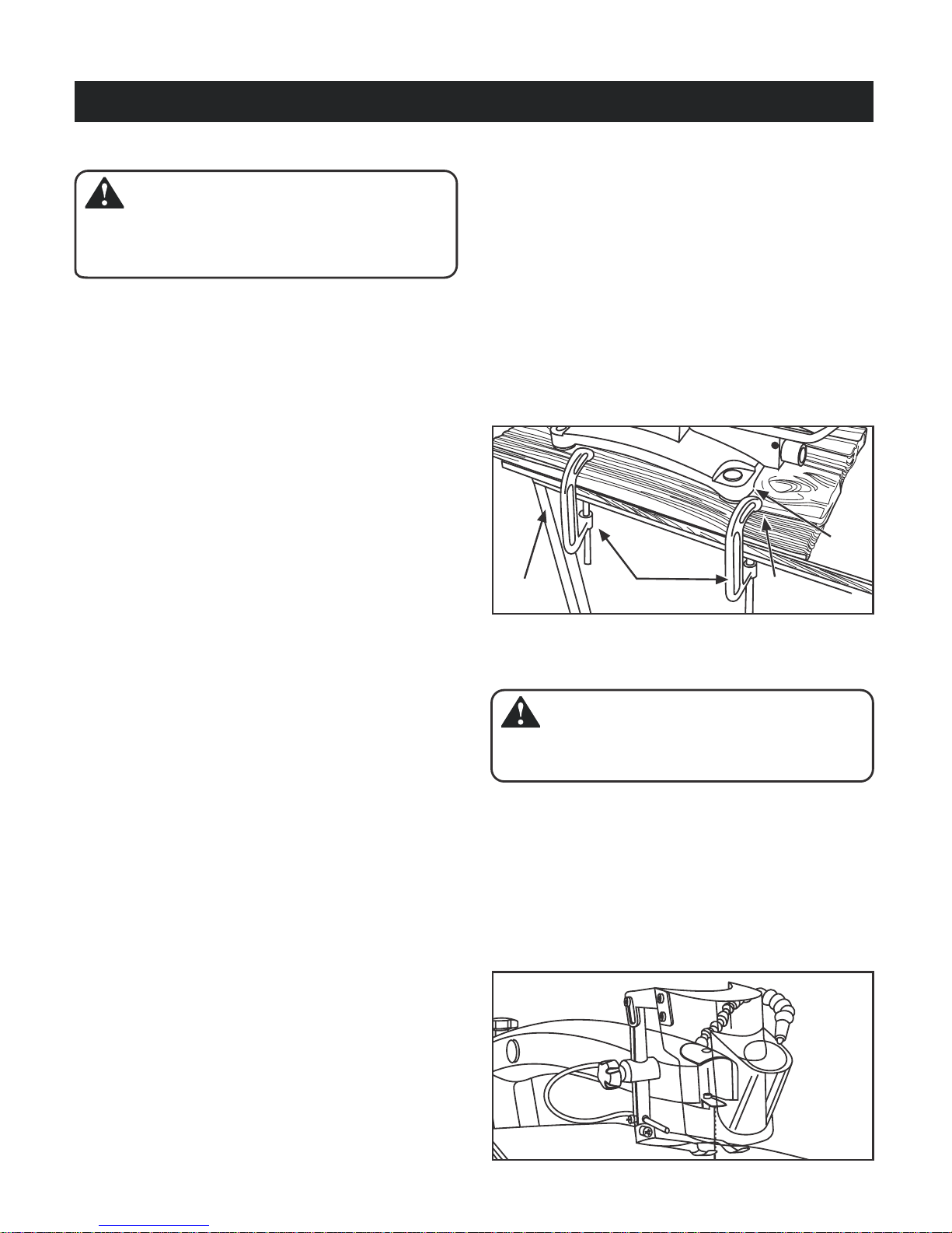
Saw
base
Work
bench
C-clamp
Mounting
board
Fig. 2
■ Insert all four bolts (not included) and tighten securely with
washers and nuts (not included).
Note: All bolts should be inserted from the top. Install the
washers and nuts from the underside of the bench.
Supporting surface where scroll saw is mounted should be
examined carefully after mounting to insure that no movement
during use can result. If any tipping or walking is noted, secure
workbench or supporting surface before beginning cutting
operations.
Reducing Noise and Vibration:
You may wish to place a foam pad or piece of carpet between
the saw base and the workbench to help reduce noise and
vibration.
If a foam pad or piece of carpet is used, do not overtighten
the mounting bolts. Leave some cushion between the padding
and the saw base to help absorb the noise and vibration. The
size of the padding material should be approximatedly 30 in.
x 15 in. x 1/2 in. (780mm x 390mm x 13mm).
CLAMPING SCROLL SAW TO WORKBENCH
See Figure 2.
If the scroll saw is to be used in a portable application, it is
recommended that you fasten it permanently to a mounting
board that can easily be clamped to a workbench or other
supporting surface. The mounting board should be of sufficient
size to avoid tipping of saw while in use. Any good grade
plywood or chipboard with a 3/4 in. (19mm) thickess is
recommended.
MOUNTING THE BLADE GUARD ON THE DROP
FOOT ROD
WARNING:
To prevent serious personal injury, pls mounting the blade
guard before using your saw.
■ Take out the blade guard from polyfoam box,
■ Use 4 mm Hex key to loose and remove the M5 screw on
the drop foot rod,
■ Use the M5 screw through the gain of the blade guard and
fix it to the drop foot rod,
■ Reasonably tight up and adjust the M5 screw to make sure
the blade guard vertical with the table
Fig. 3
Page 4
 Loading...