

RuggedCom RuggedSwitch RS1600, RuggedSwitch RS1600T, RuggedSwitch RS1600F Installation Manual
Page 1
RuggedSwitch
RuggedSwitch RS1600 Family
RuggedSwitchRuggedSwitch
16-Port Managed Fiber Optical Ethernet Switches
RS1600 Family
RS1600 Family RS1600 Family
Installation Guide
www.ruggedcom.com
RuggedCom Inc. I 30 Whitmore Road, Woodbridge, Ontario, Canada L4L 7Z4
Tel: (905) 856-5288 I Fax: (905) 856-1995 I Toll Free: (888) 264-0006
Page 2

Federal Communications Commission
Radio Frequency Interference Statement
This equipment has been tested and found to comply with the limits for a Class A digital device
pursuant to Part 15 of the FCC Rules. These limits are designed to provide reasonable protection
against harmful interference when the equipment is operated in a commercial environment. This
equipment generates, uses and can radiate radio frequency energy and, if not installed and used in
accordance with the instruction manual, may cause harmful interference to radio communications.
Operation of this equipment in a residential area is likely to cause harmful interference in which
case the user will be required to correct the interference at his expense.
Caution
This product contains a laser system and is classified as a “CLASS 1 LASER PRODUCT”.
Use of controls or adjustments or performance of procedures other than those specified herein
may result in hazardous radiation exposure. This product contains no user serviceable parts.
Attempted service by unauthorized personnel shall render all warranties null and void.
Should this device require service see the “Warranty” section of this installation guide.
Important
This unit should be installed in a restricted access location where access can only be gained by
service personnel or users who have been instructed about the reasons for the restrictions
applied to the location and about any precautions that shall be taken; and access is through the
use of a tool or lock and key, or other means of security, and is controlled by the authority
responsible for the location.
Trademarks:
Ethernet is a trademark of Xerox Corporation
RuggedSwitch, RuggedRated, ROS and eRSTP are trademarks of RuggedCom® Inc.
2008 RuggedCom Inc. All rights reserved Rev104
2
Page 3

Table of Contents
1 Product Overview.................................................................................................................... 4
1.1 Functional Overview........................................................................................... 4
1.2 Feature Highlights............................................................................................... 4
1.3 RS1600 Front Panel Description ........................................................................ 5
1.4 RS1600T Front Panel Description ...................................................................... 7
1.5 RS1600F Front Panel Description ...................................................................... 8
1.6 RS1600 Family Rear Panel Description ............................................................. 9
2 Installation ............................................................................................................................. 10
2.1 Rack Mounting.................................................................................................. 10
2.2 Power Supply Wiring and Grounding............................................................... 11
2.2.1 Single Power Supply – AC Input.............................................................. 12
2.2.2 Dual Power Supplies – AC Inputs ............................................................ 12
2.2.3 Single Power Supply – DC Input.............................................................. 13
2.2.4 Dual Power Supplies – DC Inputs ............................................................ 13
2.2.5 Dual Power Supplies – DC and AC Inputs ............................................... 14
2.3 HIPOT (Dielectric Strength) Testing................................................................ 15
2.4 Failsafe Output Wiring and Specifications ....................................................... 16
2.5 RS232 Port Wiring............................................................................................ 17
2.6 RJ45 Twisted-Pair Data Ports........................................................................... 18
3 Technical Specifications........................................................................................................ 19
3.1 Operating Environment..................................................................................... 19
3.2 Power Supply Specifications ............................................................................ 19
3.3 Failsafe Relay Specifications............................................................................ 19
3.4 Data Port Specifications.................................................................................... 19
3.5 Fiber Optical Specifications.............................................................................. 20
3.6 IEC 61850-3 Type Tests ................................................................................... 21
3.7 IEEE 1613 Type Tests ...................................................................................... 22
3.8 IEC Environmental Type Tests......................................................................... 22
3.9 Mechanical Specifications ................................................................................ 23
3.10 Agency Approvals ............................................................................................ 24
4 Warranty................................................................................................................................ 24
2008 RuggedCom Inc. All rights reserved Rev104
3
Page 4

1 Product Overview
1.1 Functional Overview
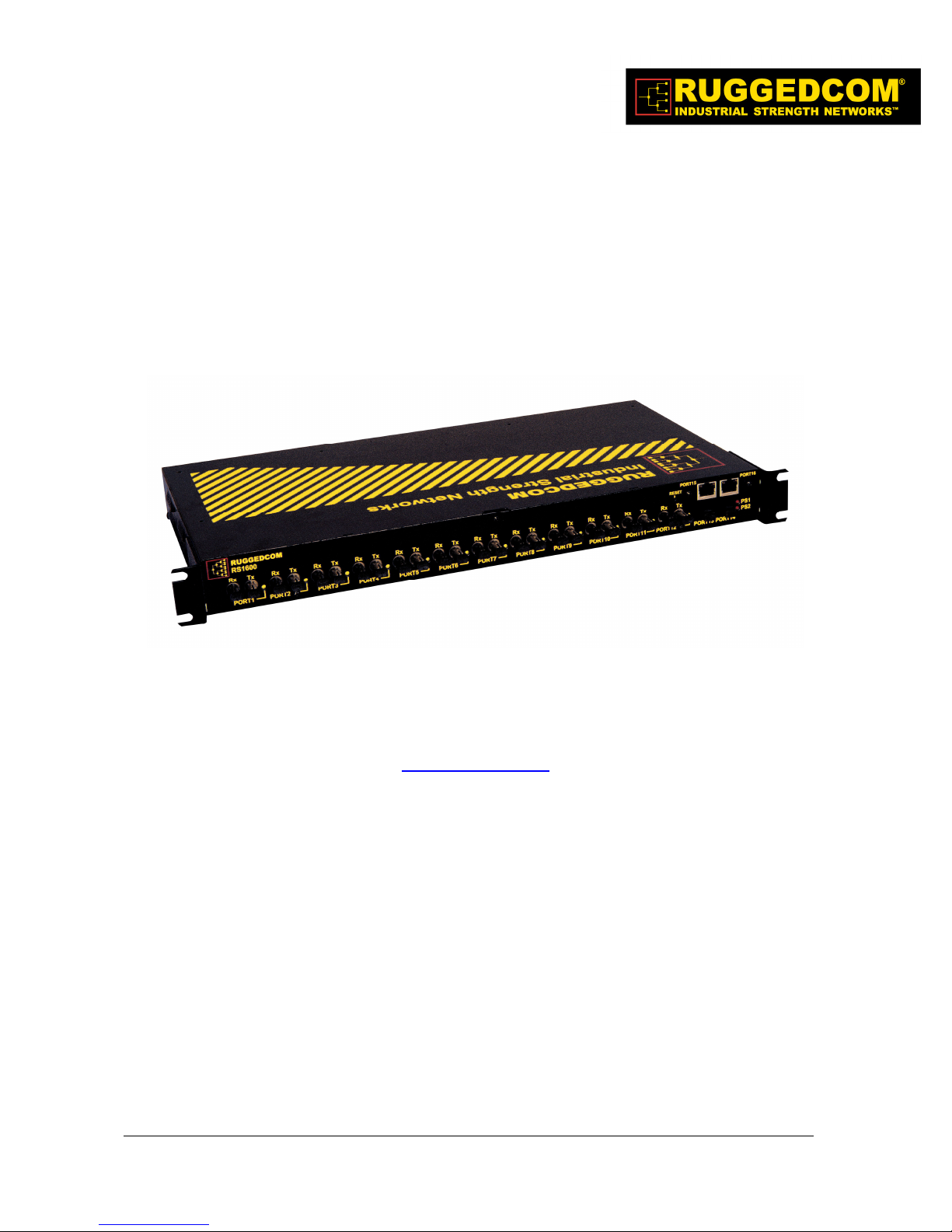
The RuggedSwitch RS1600 series are substation hardened fiber optical Ethernet switches
specifically designed to operate in harsh environments such as those found in electric utility
substations and harsh industrial environments.
Specifically tested to the same standards as mission critical protective relaying equipment, (i.e.
IEEE 1613 and IEC 60255) the RS1600 family is ideally suited to form the Ethernet network in a
UCA2 (Utility Communications Architecture 2.0) based substation automation network. Because
they were designed to meet the demands of the substation environment it is also ideally suited for
industrial automation networks based on Industrial Ethernet. The reliability of the RS1600 family
exceeds that of commercial Ethernet switches by having no rotating mechanical parts such as
cooling fans and by utilizing high-temperature solid-state components. The RS1600 series also
offers dual redundant power supplies each of which can be specified to operate from different
voltage sources which allows for increased network availability and maximum network design
flexibility.
1.2 Feature Highlights
Utility Grade (i.e. substation hardened) per IEEE 1613, IEC 60255, IEC 61850-3, IEC 61000-6-
5 standards
Operating temperature: -40° to 85°C (no fan)
Radiated RF Immunity: 35V/m per ANSI/IEEE C37.90.2
Dual, redundant power supply options: 12, 24 or 48 VDC, or HI (88-300VDC or 85-264VAC)
Failsafe output relay for critical failure or error alarming
RS1600:
12 –10BaseFL fiber optical ports
2 – 100BaseFX fiber optical uplink ports
2 – 10/100BaseTx RJ45 ports (optional)
RS1600T:
14 – 10/100BaseTx RJ45 ports
2 – 100BaseFX fiber optical uplink ports
RS1600F:
16 – 100BaseFX fiber optical ports
Advanced layer 2 switching functions: 802.1p Message Prioritization, 802.1Q VLAN
Full-duplex operation (no collisions)
2008 RuggedCom Inc. All rights reserved Rev104
4
Page 5
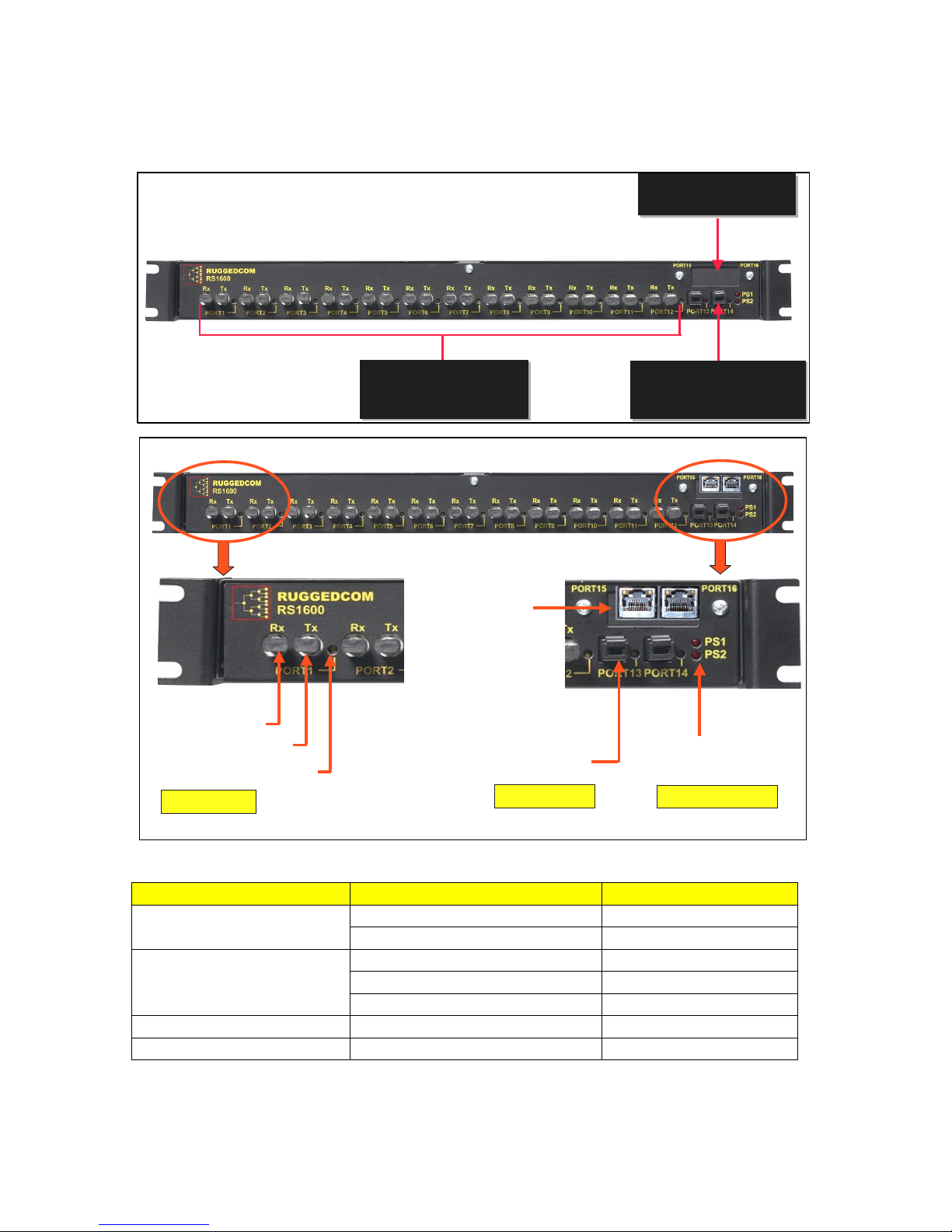
1.3 RS1600 Front Panel Description
2 – 10/100BaseTX Ports
2 – 10/100BaseTX Ports
RJ45 Connectors
RJ45 Connectors
Rx = Receive Port
Tx = Transmit Port
Link/Activity LED
10BaseFL Ports
12 - 10BaseFL Ports
12 - 10BaseFL Ports
820nm, 2km, Multimode,
820nm, 2km, Multimode,
ST Connectors
ST Connectors
10/100BaseTX
RJ45 Ports
Option
100BaseFX Port
MTRJ Connector
100BaseFX Ports
2 - 100BaseFX Ports
2 - 100BaseFX Ports
1300nm, 2km, Multimode,
1300nm, 2km, Multimode,
MTRJ Connector
MTRJ Connector
PS1 = Power Supply #1
PS2 = Power Supply #2
Power Supply LEDs
Fig. 1.3.1 RS1600 Front Panel Detail
ITEM Activity Comments
Link/Activity LED
Optional RJ45 Ports (15-16)
Link/Activity LEDs
PS1 LED Solid Power Supply 1 ON
PS2 LED Solid Power Supply 2 ON
2008 RuggedCom Inc. All rights reserved Rev104
Solid Link Established Port(1-14)
Blinking – Once per second Tx, Rx Activity
Active Right LED Link Established
Active Left LED 100BaseT Link
Inactive Left LED 10BaseT Link
5
Page 6

NOTE: If your RS1600 was ordered without the RJ45 Uplink Ports, then there will be no reset
function available although a reset label is shown on the faceplate. This does not apply to the
RS1600F and RS1600T.
2008 RuggedCom Inc. All rights reserved Rev104
6
Page 7
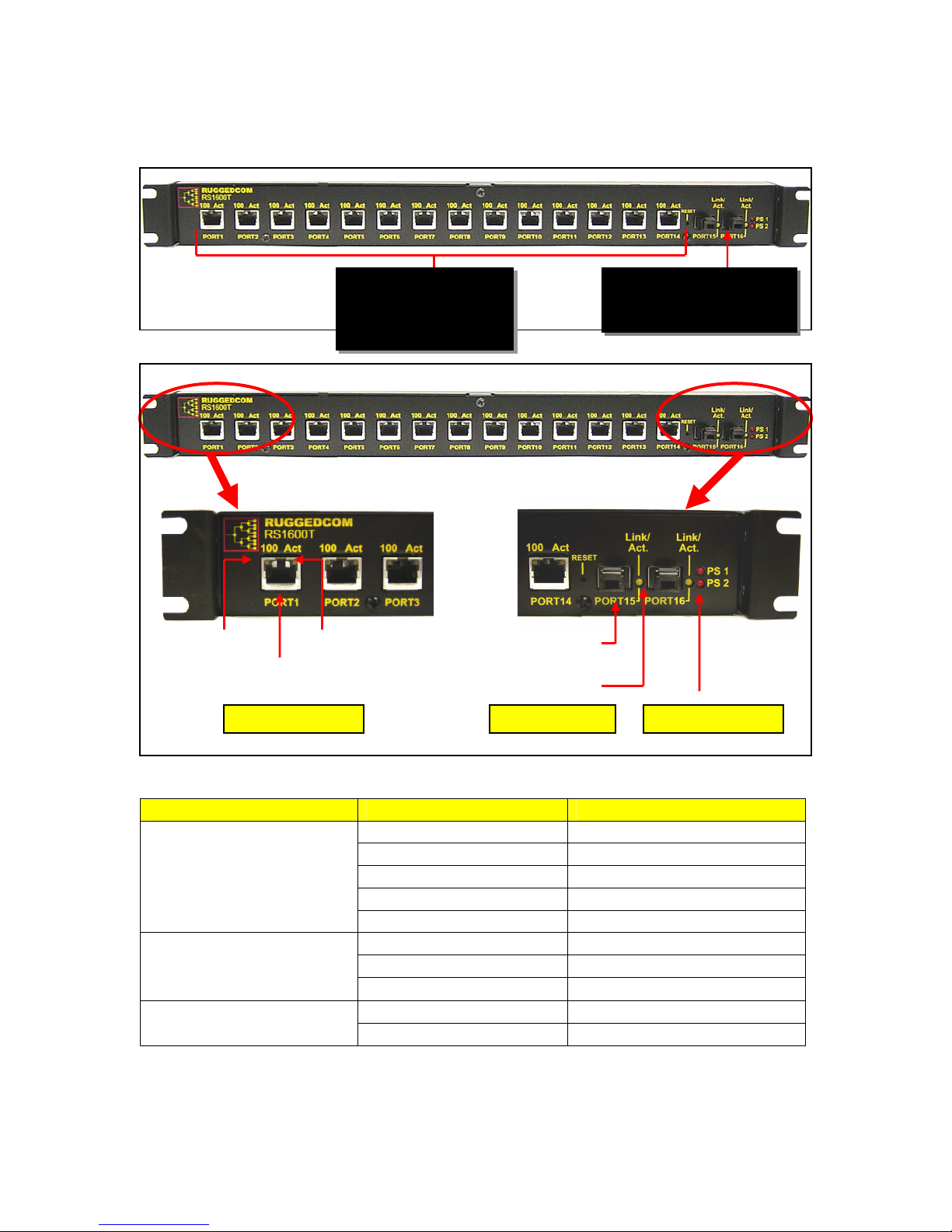
1.4 RS1600T Front Panel Description
Act LED Off
No Link Establishe
d
Off Power Supply OFF
14 – 10/100BaseTx Ports
2 – 100BaseFX Ports
Link /
10/100BaseTx Ports
100BaseFX Ports
Power Supply LEDs
Speed
RJ45 Port
100FX MTRJ
Link /Activity
Fig 1.4.1 RS1600T Front Panel Detail
100m Category 5 Cabling,
RJ45 Connectors
Activity
1300nm, 2km, Multimode
MTRJ Connector
Connector
ITEM Activity Comments
Ports 1 - 14
Link/Activity LEDs
Ports 15 – 16
Link/Activity LEDs
PS1 – PS2 LED
2008 RuggedCom Inc. All rights reserved Rev104
100 LED On 100BaseTx Link
100 LED Off 10BaseT Link
Act LED On
Link Established
Act LED Blinking Activity
LED On Link Established
LED Blinking Activity
Led Off No Link Established
On Power Supply ON
7
Page 8
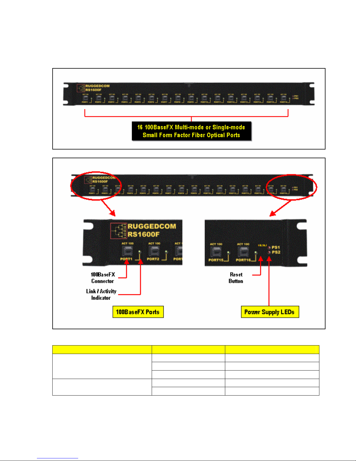
1.5 RS1600F Front Panel Description
Fig 1.5.1 RS1600F Front Panel Detail
ITEM ACTIVITY COMMENTS
Ports 1 – 16
Link/Activity LEDs
PS1 – PS2 LED
2008 RuggedCom Inc. All rights reserved Rev104
On Link Established
Blinking Activity
Off No Link Established
On Power Supply ON
Off Power Supply OFF
8
Page 9

AC (Line) or DC (+)
AC (Neutral) or DC (
- )
Surge Ground
Chassis Ground
Normally Closed
Common
Normally Open
AC (Line) or DC (+)
AC (Neutral) or DC (
- )
Surge Ground
Chassis Ground
Failsafe Output Relay
Power Supply #1
Power Supply #2
RS232 Port
PIN 1
PIN5
PIN 6
PIN9
PIN
SIGNAL
1 n.c.
2 TXD
3 RXD
4 n.c.
5 GND
6
n.c.
7 n.c.
8 n.c.
9 n.c.
1.6 RS1600 Family Rear Panel Description
Primary Power Supply
Primary Power Supply
24/48VDC
120-300VDC (120/230VAC)
120-300VDC (120/230VAC)
24/48VDC
Failsafe
Failsafe
Output
Output
Relay
Relay
Fig 1.6.1 RS1600 Family Rear Panel Description
RS1600 / RS1600T Rear Panel Detail
Fig. 1.6.2 RS1600 Family Rear Panel Detail
RS232
RS232
Port
Port
Secondary Power Supply
Secondary Power Supply
24/48VDC
120-300VDC (120/230VAC)
120-300VDC (120/230VAC)
24/48VDC
2008 RuggedCom Inc. All rights reserved Rev104
9
Page 10

2 Installation
19” Rack Mounting
Mounting
Brackets
Step 1: Attach 19”
mounting brackets
using # 6
- 32 screws.
Step 2: Mount to
19” Rack using # 10
- 32
screws.
2.1 Rack Mounting
Fig. 2.1.1 RS1600 Family 19” Rack Mounting
NOTE: Since heat within RS1600 products is channeled to the enclosure, it is recommended that
1 rack unit of space (1.75”) be kept unpopulated and free of equipment above each RS1600 series
product to allow for a small amount of convectional airflow. Although forced airflow is not
necessary, any increase in airflow will result in a reduction of ambient temperature that will improve
long-term reliability of all equipment mounted within the rack space.
10
2008 RuggedCom Inc. All rights reserved Rev104
Page 11

2.2 Power Supply Wiring and Grounding
AC (Line) or DC
(+)
Surge Ground
Chassis Ground
Surge Ground
Chassis Ground
AC (Neutral) or DC (
-
)
AC (Line) or DC (+)
AC (Neutral) or DC (
-
)
RS1600 / RS1600T Power Supply Inputs
Fig. 2.2.1 RS1600 Family Power Supply Inputs
The RS1600 family supports dual redundant power supplies – “Power Supply 1” and “Power
Supply 2” (see Fig. 2.2.1). Each power supply as a set of identical inputs that perform the following:
1. +/H is connected to the positive (+) terminal if the power source is DC or to the (Hot)
terminal if the power source is AC.
2. -/N is connected to the negative (-) terminal if the power source is DC or to the (Neutral)
terminal if the power source is AC.
3. Surge Ground is connected to the Chassis Ground via a braided cable or other
appropriate grounding wire. Surge Ground is used as the ground conductor for all surge
and transient suppression circuitry internal to the RS1600. NOTE: Surge Ground must be
disconnected from Chassis Ground during HIPOT (dielectric strength) testing.
4. Chassis Ground is connected to the Safety Ground terminal for AC inputs or the
equipment ground bus for DC inputs.
Sections 2.2.1 to 2.2.5 describe connections for single, dual and mixed AC and DC power supply
inputs.
2008 RuggedCom Inc. All rights reserved Rev104
11
Page 12

2.2.1 Single Power Supply – AC Input
Fig. 2.2.2 Single Power Supply – AC Input
2.2.2 Dual Power Supplies – AC Inputs
Fig. 2.2.3 Dual Power Supplies – AC Inputs
2008 RuggedCom Inc. All rights reserved Rev104
12
Page 13

2.2.3 Single Power Supply – DC Input
Fig. 2.2.4 Single Power Supply – DC Input
2.2.4 Dual Power Supplies – DC Inputs
Fig. 2.2.5 Dual Power Supplies – DC Inputs
2008 RuggedCom Inc. All rights reserved Rev104
13
Page 14

2.2.5 Dual Power Supplies – DC and AC Inputs
Fig. 2.2.6 Dual Power Supplies – DC and AC Inputs
NOTES:
1. 88-300VDC rated equipment: A 300VDC appropriately rated circuit breaker must be
installed within 3m of unit.
2. 100-240VAC rated equipment: A 250VAC appropriately rated circuit breaker must be
installed within 3m of unit.
3. A circuit breaker is not required for 12, 24 or 48 VDC rated power supplies.
4. Separate circuit breakers must be installed and separately identified.
5. Equipment must be installed according to the applicable country wiring codes.
2008 RuggedCom Inc. All rights reserved Rev104
14
Page 15

2.3 HIPOT (Dielectric Strength) Testing
HIPOT (Dielectric Strength) Testing
Disconnect Braided Cable (1) and Braided Cable (2) during
HIPOT (dielectric strength) testing!
Power Supply
#1
Braided Cable
(1)
Power Supply
Braided Cable
#2
(2)
Fig. 2.3.1 HIPOT (Dielectric Strength) Testing
NOTE: Units which are to be “HIPOT” tested in the field must have the braided ground cable(s)
disconnected (see Fig. 2.3.1) during the HIPOT test. This is required in order to prevent the
transient/surge suppression circuitry, which is connected to Surge Ground (see Fig. 2.2.1), from
being activated during the HIPOT test.
2008 RuggedCom Inc. All rights reserved Rev104
15
Page 16

2.4 Failsafe Output Wiring and Specifications
The “Failsafe” output relay is provided to signal critical error conditions that may occur on the
RS1600 series switches. The contacts are energized upon power up of the unit and remain
energized until a critical error occurs. One common application for this output, regardless of
whether the switch is managed or unmanaged, is to signal an alarm if a power failure or removal of
control power occurs.
RS1600 Failsafe Relay Outputs
Normally Closed Common Normally Open
*** Normal contact state prior to power being applied to unit. ***
Fig. 2.4.1 Failsafe Output Relay
2008 RuggedCom Inc. All rights reserved Rev104
16
Page 17

2.5 RS232 Port Wiring
The RS232 port is used for configuring the RS1600 / RS1600T when the management CPU is
present. The management CPU is present if the order code contains the “MS” option (e.g. RS1600xx-xx-xx-MS-xx). A straight-through serial cable with a DB-9 connector is required. There is no
need to cross-over the TXD and RXD signals from the PC side since this has been done internally
as is shown in Fig. 2.5.1.
Pin Signal
1 No Connection
2 Transmit Data
3 Receive Data
4 No Connection
5 Ground
6 No Connection
7 No Connection
8 No Connection
9 No Connection
Fig 2.5.1 RS232 Port Signals
NOTE: This port is not intended to be a permanent connection and the cable shall be less than 2m
(6.5 ft) in length.
2008 RuggedCom Inc. All rights reserved Rev104
17
Page 18

2.6 RJ45 Twisted-Pair Data Ports
RS1600 series switches may have 10/100BaseTX ports that allow connection to standard CAT-5
UTP cable with RJ45 male connectors. The RJ45 receptacles are directly connected to the chassis
ground on the RS1600 and can accept shielded CAT-5 cables. If shielded cables are used, care
must be taken to ensure the shielded cables do not form a ground loop via the shield wire and the
RJ45 receptacles at either end.
All RJ45 RuggedSwitch products feature auto-negotiating, auto-polarity, and auto-crossover
functions with the exception of the base RS1600 model (port 15 and 16 only). The base RS1600
(RS1600-XX-XX-XX-XX-RJ) is not auto-crossover capable. Fig. 2.6.1 shows the RJ45 port pins
configuration.
Pin Signal
1 +Rx
2 -Rx
3 +Tx
4 No Connection
5 No Connection
6 -Tx
7 No Connection
8 No Connection
Case Shield (Chassis Ground)
Fig. 2.6.1 shows the RJ45 port pins configuration.
NOTE: RuggedCom does not recommend the use of CAT-5 cabling of any length for critical realtime substation automation applications. However, transient suppression circuitry is present on all
copper ports to protect against damage from electrical transients and to ensure IEC 61850-3 and
IEEE 1613 Class 1 conformance. This means that during the transient event communications
errors or interruptions may occur but recovery is automatic.
RuggedCom also does not recommended to use these ports to interface to field devices across
distances which could produce high levels of ground potential rise, (i.e. greater than 2500V) during
line to ground fault conditions.
2008 RuggedCom Inc. All rights reserved Rev104
18
Page 19

3 Technical Specifications
3.1 Operating Environment
Parameter Range Comments
Ambient Operating Temperature
Ambient Relative Humidity 5% to 95% Non-condensing
Ambient Storage Temperature
-40 to 85°C
-40 to 85°C
3.2 Power Supply Specifications
Input Range Max. Power Consumption Power Supply Type
Min Max
12 – 24 VDC 10 VDC 36 VDC 6.3A(F) 2 1.5 kV DC
24 VDC 18 VDC 36 VDC 5A(F) 2 1.5 kV DC
48 VDC 36 VDC 59 VDC 2A(T) 2 1.5 kV DC
HI (125/250 VDC) 1
HI (110/230 VAC) 1
NOTES:
1. This is the same power supply for both AC and DC.
2. (F) Denotes fast-acting fuse, (T) denotes time-delay fuse
3. For continued protection against risk of fire, replace only with same type and rating of fuse.
88 VDC
85 VAC
300 VDC
265 VAC
Fuse
Rating
2A(T)
1,2
Isolation
4 kV AC 5.5
kV DC
Ambient Temperature as
measured from a 30 cm radius
surrounding the center of the
RS1600 enclosure.
RS1600 RS1600T RS1600F
30 W 21 W 34 W
3.3 Failsafe Relay Specifications
Parameter Value
Max Switching Voltage 30VAC, 80VDC
Rated Switching Current 0.3A @ 30VAC
1A @ 30VDC, 0.3A @ 80VDC
3.4 Data Port Specifications
Data Port Media Distance Connector Type
10/100 Mbps* Cat 5 UTP 100m RJ45
*Available as an option on RS1600
19
2008 RuggedCom Inc. All rights reserved Rev104
Page 20

3.5 Fiber Optical Specifications
Speed
Standard
10BaseFL MM / ST 820 50/125 -16.5/-10.6 -34.4 -11.2 2 21
100BaseFX MM / MTRJ 1310 50/125 -16/-11 -33.5 -11 2 17
100BaseFX SM / LC 1310 9/125 -15/-8 -31 -5 15 16.5
Mode /
Connector
Tx
(nm)
λλλλ
Cable
Type
(
µµµµ
m)
2
Tx Pwr
(dBm peak) 3
(Min / Max)
Rx
Sensitivity
(dBm Average) 3
Rx Saturation
(dBm Peak) 3
Typical
Distance
(km) 1
Power
Budget
(dB)
NOTES:
1. Maximum segment length is greatly dependent on factors such as fiber quality, and
number of patches and splices. Please consult RuggedCom sales associates when
determining maximum segment distances.
2. To convert from average to peak add 3dBm. To convert from peak to average, subtract
3dBm.
3. Single-mode is available as an option.
2008 RuggedCom Inc. All rights reserved Rev104
20
Page 21

3.6 IEC 61850-3 Type Tests
Test Description Test Levels
IEC 61000-4-2 ESD
IEC 61000-4-3 Radiated RFI Enclosure ports 20 V/m x
IEC 61000-4-4
IEC 61000-4-5 Surge
IEC 61000-4-6
IEC 61000-4-8 Magnetic Field Enclosure ports 40 A/m continuous, 1000 A/m for 1 s N/A
IEC 61000-4-29
IEC 61000-4-11
IEC 61000-4-12
IEC 61000-4-16
IEC 61000-4-17
IEC 60255-5 Dielectric Strength
IEC 60255-5 H.V. Impulse
Burst (Fast
Transient)
Induced
(Conducted) RFI
Voltage Dips &
Interrupts
Damped
Oscillatory
Mains Frequency
Voltage
Ripple on D.C.
Power Supply
Enclosure Contact +/- 8kV 4
Enclosure Air +/- 15kV 4
Signal ports +/- 4kV @ 2.5kHz x
D.C. Power ports +/- 4kV 4
A.C. Power ports +/- 4kV 4
Earth ground ports +/- 4kV 4
Signal ports
D.C. Power ports
A.C. Power ports
Signal ports 10V 3
D.C Power ports 10V 3
A.C. Power ports 10V 3
Earth ground ports 10V 3
D.C. Power ports
A.C. Power ports
Signal ports
D.C. Power ports
A.C. Power ports
Signal ports 30V Continuous, 300V for 1s 4
D.C. Power ports 30V Continuous, 300V for 1s 4
D.C. Power ports 10% 3
Signal ports 2kV AC (Fail-Safe Relay output) N/A
D.C. Power ports 2kV AC N/A
A.C. Power ports 2kV AC N/A
Signal ports 5kV (Fail-Safe Relay output) N/A
D.C. Power ports 5kV N/A
A.C. Power ports 5kV N/A
+/- 4kV line-to-earth, +/- 2kV line-to-
line
+/- 2kV line-to-earth, +/- 1kV line-to-
line
+/- 4kV line-to-earth, +/- 2kV line-to-
line
30% for 0.1s, 60% for 0.1s, 100% for
0.05s
30% for 1 period, 60% for 50 periods N/A
100% for 5 periods, 100% for 50
periods 2
2.5kV common, 1kV differential mode
@ 1MHz
2.5kV common, 1kV differential mode
@ 1MHz
2.5kV common, 1kV differential mode
@ 1MHz
Severity
Levels
N/A
N/A
4
3
4
3
3
3
2008 RuggedCom Inc. All rights reserved Rev104
21
Page 22

3.7 IEEE 1613 Type Tests
IEEE Test IEEE 1613
Clause
C37.90.3 9 ESD
C37.90.2 8 Radiated RFI Enclosure ports 35 V/m
C37.90.1 7 Fast Transient
C37.90.1 7 Oscillatory
C37.90 6 H.V. Impulse
C37.90 6 Dielectric Strength
NOTE:
• If the unit contains copper ports the IEEE 1613 conformance is Class 1 (During disturbance errors may occur but
recovery is automatic).
• If the unit contains all fiber ports the IEEE 1613 conformance is Class 2 (During disturbance no errors will occur).
Description Test Levels
Enclosure Contact +/- 8kV
Enclosure Air +/- 15kV
Signal ports +/- 4kV @ 2.5kHz
D.C. Power ports +/- 4kV
A.C. Power ports +/- 4kV
Earth ground ports +/- 4kV
Signal ports 2.5kV common mode @ 1MHz
D.C. Power ports 2.5kV common & differential mode @ 1MHz
A.C. Power ports 2.5kV common & differential mode @ 1MHz
Signal ports 5 kV (Failsafe Relay)
D.C. Power ports 5 kV
A.C. Power ports 5 kV
Signal ports 2kV AC(Failsafe Relay)
D.C. Power ports 2kV AC
A.C. Power ports 2kV AC
3.8 IEC Environmental Type Tests
Test Description Test Levels
IEC 60068-2-1 Cold Temperature Test Ad -40 deg. C, 16 Hours N/A
IEC 60068-2-2 Dry Heat Test Bd +85 deg. C, 16 Hours N/A
IEC 60068-2-30
IEC 60255-21-1 Vibration Tests Fc 2g @ (10-150) Hz Class 2
IEC 60255-21-2 Shock Tests Ea 30g @ 11 ms Class 2
Humidity (Damp Heat,
Cyclic)
Test Db 95% (non-condensing), 55°C, 6 cycles N/A
22
2008 RuggedCom Inc. All rights reserved Rev104
Severity
Levels
Page 23

3.9 Mechanical Specifications
Parameter Value Comments
Dimensions
Weight 10 lb (4.5 Kg)
Enclosure 18 gauge Galvanized Steel
18.29 x 10.17 x 1.74 inches
(464,57) x (258,32) x (44,20) mm
(Length x Width x Height)
with mounting brackets
installed
2008 RuggedCom Inc. All rights reserved Rev104
23
Page 24

3.10 Agency Approvals
Agency Standards Comments
CSA CSA C22.2 No. 60950, UL 60950
CE EN 60950, EN 61000-6-2
FCC FCC Part 15, Class A Approved
CISPR EN55022, Class A Approved
FDA/CDRH 21 CFR Chapter 1, Subchapter J Compliant
IEC/EN EN60825-1:1994 + A11:1996 + A2:2001 Compliant
Approved
Approved
4 Warranty
RuggedCom warrants this product for a period of five (5) years from date of purchase. For
warranty details, visit http://www.ruggedcom.com/ or contact your customer service representative.
Should this product require warranty or service contact the factory at:
RuggedCom Inc.
30 Whitmore Road,
Woodbridge, Ontario
Canada L4L 7Z4
Phone: (905) 856-5288
Fax: (905) 856-1995
2008 RuggedCom Inc. All rights reserved Rev104
24
 Loading...