

RuggedCom RuggedRouter RX1000 Family Installation Manual
RuggedRouter®
RX1000 Family
Industrially Hardened
Cyber Security Appliance
Installation Guide
August 2, 2011
www.ruggedcom.com

Corporate Headquarters
US Headquarters
Europe Headquarters
RuggedCom Inc.
300 Applewood Crescent
Concord, Ontario
Canada, L4K 5C7
Tel: +1 905 856 5288
Fax: +1 905 856 1995
Toll-free: 1 888 264 0006
RuggedCom
1930 Harrison St., Suite 209
Hollywood, Florida
USA, 33020
Tel: +1 954 922 7938 ext. 103
Fax: +1 954 922 7984
Toll-free: 1 888 264 0006
RuggedCom
Unit 41, Aztec Centre,
Aztec West, Almondsbury, Bristol
United Kingdom BS32 4TD
Tel: +44 1454 203 404
Fax: +44 1454 203 403
Email: RuggedSales@RuggedCom.com
Technical Support
Toll Free (North America): 1 866 922 7975
International: +1 905 856 5288
Email: Support@RuggedCom.com
Copyright
COPYRIGHT © 2011 RuggedCom Inc. ALL RIGHTS RESERVED
Dissemination or reproduction of this document, or evaluation and communication of its contents, is not
authorized except where expressly permitted. Violations are liable for damages. All rights reserved,
particularly for the purposes of patent application or trademark registration.
This document contains proprietary information, which is protected by copyright. All rights are reserved.
No part of this document may be photocopied, reproduced or translated to another language without
the prior written consent of RuggedCom Inc.
Disclaimer of liability
We have checked the contents of this manual against the hardware and software described. However,
deviations from the description cannot be completely ruled out.
RuggedCom shall not be liable for any errors or omissions contained herein or for consequential
damages in connection with the furnishing, performance, or use of this material.
The information given in this document is reviewed regularly and any necessary corrections will be
included in subsequent editions. We appreciate any suggested improvements. We reserve the right to
make technical improvements without notice.
Registered Trademarks
RuggedRated™, ROS™ and eRSTP™ are trademarks of RuggedCom Inc. RuggedRouter® and
RuggedSwitch® are registered trademarks of RuggedCom Inc. Other designations in this manual might
be trademarks whose use by third parties for their own purposes would infringe the rights of the owner.
Contacting RuggedCom
Web: www.RuggedCom.com

Caution
This product contains a laser system and is classified as a “CLASS 1 LASER PRODUCT”.
Use of controls or adjustments or performance of procedures other than those specified herein may result in hazardous
radiation exposure. This product contains no user-serviceable parts. Attempted service by unauthorized personnel shall
render all warranties null and void.
Should this device require service, see the “Warranty” section of this installation guide.
Important Notice for Cellular Options
If this equipment is ordered with one of the cellular radio options, it must be installed and operated with the following
guidelines to ensure safe operation and maintain compliance.
Cellular Safety And Hazards
Do not operate the cellular modem in:
Areas where blasting is in progress.
Explosive atmospheres like refueling points, fuel depots and chemical plants.
Near equipment that is susceptible to any form of radio interference like medical and life support equipment.
Maintain at least 20 cm separation distance between the antenna and user’s body at all times.
Ensure that the maximum gain stated for the cellular option selected is not exceeded to keep RF radiation within
limits of FCC/IC regulations.
Federal Communications Commission Radio
Frequency Interference Statement
This equipment has been tested and found to comply with the limits for a Class A digital device pursuant to Part 15 of the FCC
Rules. These limits are designed to provide reasonable protection against harmful interference when the equipment is
operated in a commercial environment. This equipment generates, uses and can radiate radio frequency energy and, if not
installed and used in accordance with the instruction manual, may cause harmful interference to radio communications.
Operation of this equipment in a residential area is likely to cause harmful interference in which case the user will be required
to correct the interference at his expense.

Table of Contents
Table of Contents
Federal Communications Commission Radio Frequency Interference Statement ........... 3
Table of Contents .............................................................................................................. 4
Table of Figures ................................................................................................................ 5
Table of Tables ................................................................................................................. 6
1 Product Overview ....................................................................................................... 7
1.1 Functional Overview ........................................................................................... 7
1.2 Feature Highlights ............................................................................................... 7
2 Panel Description ....................................................................................................... 9
2.1 Display Panel Description ................................................................................... 9
2.2 Ethernet Panel Description ............................................................................... 11
3 Installation ................................................................................................................ 12
3.1 Mounting ........................................................................................................... 12
3.2 Power Supply Wiring and Grounding ................................................................ 15
3.3 Failsafe Alarm Relay Wiring ............................................................................. 23
3.4 Console Port Wiring .......................................................................................... 24
4 Communication Ports ............................................................................................... 25
4.1 RJ45 Twisted-Pair Data Ports .......................................................................... 25
4.2 Fiber Optic Ethernet Ports ................................................................................ 26
4.3 WAN Ports ........................................................................................................ 28
4.4 DSL ................................................................................................................... 29
4.5 DDS .................................................................................................................. 30
4.6 Modem Port ...................................................................................................... 31
4.7 Serial Card ........................................................................................................ 32
4.8 RS485 Wiring .................................................................................................... 33
4.9 Transient Protection on Communication Ports ................................................. 34
4.10 Precision Time Protocol (PTP) Card ................................................................. 34
4.11 RS232 EXT Modem Card ................................................................................. 39
4.12 Cellular Modems ............................................................................................... 40
5 Technical Specifications .......................................................................................... 43
5.1 Power Supply Specifications ............................................................................ 43
5.2 Failsafe Relay Specifications ............................................................................ 43
5.3 Twisted-Pair Port Specifications ....................................................................... 44
5.4 Fiber Optic Specifications ................................................................................. 44
5.5 IEC 61850-3 Type Tests ................................................................................... 45
5.6 IEEE 1613 Type Tests ...................................................................................... 46
5.7 Environmental Type Tests ................................................................................ 47
5.8 Operating Environment ..................................................................................... 47
5.9 Agency Approvals ............................................................................................. 47
5.10 Cellular Modem Certifications ........................................................................... 48
5.11 Mechanical Specifications ................................................................................ 49
6 Warranty .................................................................................................................. 50
RuggedCom® - Rev.122 4 RuggedRouter® RX1000 Family

Table of Figures
Table of Figures
Figure 1: LED Display Panel ............................................................................................. 9
Figure 2: Ethernet panel LED description ....................................................................... 11
Figure 3: RX1000 Rack mount orientation options ......................................................... 12
Figure 4: 19” Rack Mount Adapters ................................................................................ 13
Figure 5: Rack mount adapter mounting location ........................................................... 13
Figure 6: RX1000 Panel/DIN Rail mounting diagram ...................................................... 14
Figure 7: RX1000 Series Phillips Screw Terminal Block ................................................. 15
Figure 8: RX1000 Series Phoenix Plug Terminal Block .................................................. 15
Figure 9: Chassis Ground Connection ............................................................................ 16
Figure 10: AC Single Power Supply Wiring Example ...................................................... 18
Figure 11: AC Dual Redundant Power Supply Wiring Example ...................................... 18
Figure 12: DC Power Supply Wiring Examples ............................................................... 19
Figure 13: DC and AC Power Supply Wiring Example ................................................... 20
Figure 14: AC Input to PS1 and 48VDC Input to PS2 for PoE ........................................ 21
Figure 15: Dielectric Strength (HIPOT) Testing .............................................................. 22
Figure 16: Failsafe Alarm Relay Wiring ........................................................................... 23
Figure 17: Console port location on display board .......................................................... 24
Figure 18: RX1000 Console cable .................................................................................. 24
Figure 19: RJ45 jack pin configuration ............................................................................ 25
Figure 20: 10FL ST connector ........................................................................................ 27
Figure 21: 100FX MTRJ connector ................................................................................. 27
Figure 22: 100FX / 1000LX LC connector ....................................................................... 27
Figure 23: 100FX / 1000LX SC connector ...................................................................... 27
Figure 24: 100FX / 1000LX ST connector ....................................................................... 27
Figure 25: RJ45 jack pin configuration ............................................................................ 28
Figure 26: WAN (T1/E1) Card location ........................................................................... 28
Figure 27: RJ11 jack pin configuration ............................................................................ 29
Figure 28: RJ45 jack pin configuration ............................................................................ 30
Figure 29: RJ11 jack pin configuration ............................................................................ 31
Figure 30: V.90 Modem Card location ............................................................................ 31
Figure 31: RS232/RS485/RS422 via RJ45 pinout .......................................................... 32
Figure 32: Conceptual RS485 wiring diagram ................................................................ 33
Figure 33: PTP Card Panel Description .......................................................................... 35
Figure 34: IRIG-B Simplified Schematic .......................................................................... 38
Figure 35: DB9 (female) pin configuration ...................................................................... 39
Figure 36: EVDO Modem Faceplate ............................................................................... 40
Figure 37: HSPA Modem Faceplate ............................................................................... 41
Figure 38: SIM Card Access for GSM/EDGE Internal Modem ........................................ 42
Figure 39: RX1000 Series mechanical dimensions ........................................................ 49
RuggedRouter® RX1000 Family 5 RuggedCom® - Rev.122

Table of Tables
Table of Tables
Table 1: LED Display – Device status LED behavior definition ....................................... 10
Table 2: LED Display – Port Status behavior definition .................................................. 10
Table 3: RX1000/RX1100 Power terminal block connection description ........................ 16
Table 4: RX1000P/RX1100P power supply connection differences ............................... 17
Table 5: RS232 over RJ45 console cable pinout ............................................................ 24
Table 6: RJ45 Ethernet pin assignment .......................................................................... 25
Table 7: RJ45 T1/E1 pin assignment .............................................................................. 28
Table 8: ADSL RJ11 pin configuration ............................................................................ 29
Table 9: RJ45 DDS pin assignment ................................................................................ 30
Table 10: Modem RJ11 pin configuration ....................................................................... 31
Table 11: RS232/RS485/RS422 via RJ45 pinout ........................................................... 32
Table 12: GPS Antenna Specifications ........................................................................... 36
Table 13: Coaxial Cable Delay ........................................................................................ 37
Table 14: IRIG-B Output Specifications .......................................................................... 38
Table 15: RS232 EXT Modem Card pinout ..................................................................... 39
Table 16: Verizon Contact Numbers ............................................................................... 40
Table 17: EVDO Antenna Requirements ........................................................................ 40
Table 18: HSPA Antenna Requirements ......................................................................... 42
Table 19: GSM/EDGE Antenna Requirements ............................................................... 42
Table 20: Main Power Supply Specifications .................................................................. 43
Table 21: PoE Power Supply Specifications ................................................................... 43
Table 22: Failsafe Relay Specifications .......................................................................... 43
Table 23: Twisted-Pair Port Specifications ..................................................................... 44
Table 24: Fiber Optic Specifications ............................................................................... 44
Table 25: IEC 61850-3 Type Tests ................................................................................. 45
Table 26: IEEE 1613 Type Tests .................................................................................... 46
Table 27: Environmental Type Tests .............................................................................. 47
Table 28: Operating Environment ................................................................................... 47
Table 29: Agency Approvals ........................................................................................... 47
Table 30: Cellular Modem Certifications ......................................................................... 48
Table 31: RX1000 Series Mechanical Specifications ...................................................... 49
RuggedCom® - Rev.122 6 RuggedRouter® RX1000 Family

Product Overview
1 Product Overview
1.1 Functional Overview
The RuggedRouter® family of products consists of industrially hardened cyber
security appliances with integrated router, firewall, and VPN functionality. The family
includes the RX1000, RX1000P, RX1100, and RX1100P. The RX1000 series can be
used to establish an electronic security perimeter around critical cyber assets found
in control and automation systems, in order to prevent the disruption of operations by
accidental or malicious acts. Ideally suited for electric power utilities, the industrial
plant floor, and traffic control systems, the RX1000 series is designed to protect and
secure SCADA system networks connected to the Internet, or within a company‟s
Wide Area Network (WAN) or Local Area Network (LAN). The RX1100 adds
Intrusion Detection and RuggedCom Gauntlet® for NERC CIP compliance.
The RX1000 series includes security functions such as full IPSec Virtual Private
Network (VPN), and firewall capabilities with the capacity to connect hundreds of
remote sites over Frame Relay and PPP. The modular architecture allows the
customization of the number and type of Ethernet and WAN ports. Integrated
modem, serial interface, and time synchronization options are also available.
The RX1000 series is hardened to the RuggedRatedTM specification which provides
a high level of immunity to electromagnetic interference (EMI) and heavy electrical
surges typical of the harsh environments found in many industrial applications. An
operating temperature range of -40 to +85°C (-40 to 185° F) allows the RX1000 to be
placed in almost any location.
For applications requiring high availability, the RX1000 and RX1100 provide the
option for integrated dual redundant power supplies, each capable of
accommodating a wide range of input voltages for worldwide operability. Also unique
is the ability to have each power supply fed from different voltage levels and/or
sources thereby providing great flexibility in creating high availability systems. The
RX1000P and RX1100P provide IEEE 802.3af standard Power over Ethernet (PoE)
on their 10/100BaseTx ports.
1.2 Feature Highlights
Security Appliance Functions
Integrated Router/Firewall/VPN
Stateful Firewall with NAT
Full IPSec Virtual Private Networking
VPN with 3DES, DES and AES support
RuggedRated™ for Reliability in Harsh Environments
Meets IEEE 1613 (electric utility substations)
Exceeds IEC 61850-3 (electric utility substations)
Exceeds IEEE 61800-3 (variable speed drive systems)
Exceeds IEC 61000-6-2 (generic industrial environment)
Exceeds NEMA TS-2 (traffic control equipment)
RuggedRouter® RX1000 Family 7 RuggedCom® - Rev.122

Product Overview
-40 to +85°C operating temperature (no fans)
Conformal coated printed circuit boards (optional)
18 AWG galvanized steel enclosure
Power Supply Options
Fully integrated, dual-redundant (optional) power supplies (RX1000/RX1100)
Power over Ethernet (PoE) on 10/100BaseTx ports (RX1000P/RX1100P)
Universal high-voltage range: 88-300VDC or 85-264VAC
Popular low voltage DC ranges: 12, 24 or 48 VDC
Terminal blocks for reliable, maintenance free connections
CSA/UL 60950 safety approved to +85°C
Physical Ports
Ethernet Options (up to 4 ports):
o 10/100BaseTX (with PoE on RX1000P and RX1100P)
o 100BaseFX
WAN Port Options (up to 8 ports):
o T1/E1 (channelized/unchannelized) supports 2 Mbps G.703 with 120 ohm
balanced connections
o T3/E3 DS3
o 56 Kbps DDS
o DSL (supports G.992.1, G.992.2, G.992 Annex A)
Serial Ports (up to 8 ports):
o Fully compliant EIA/TIA RS485, RS422, RS232 software selectable serial
ports
o Raw socket mode support allows conversion of any serial protocol
Embedded Modem Port
Embedded EvDO – CDMA cellular modem
Embedded HSPA – GSM cellular modem
GPS / IRIG-B / IEEE 1588 Time Sync
Protocols
WAN
o Frame Relay RFC 1490 or RFC 1294
o PPP RFC 1661, 1332, 1321, 1334
o PPPoE over DSL, PAP, CHAP Authentication
IP
o Routing
o VRRP, OSPF, DHCP Agent
o Traffic prioritization, NTP Host (Stratum 2)
Frame Relay Support
ISO and ITU compliant, network certified
ANSI T1.617 Annex D, Q.933 or LMI Local Signaling
RuggedCom® - Rev.122 8 RuggedRouter® RX1000 Family
Panel Description
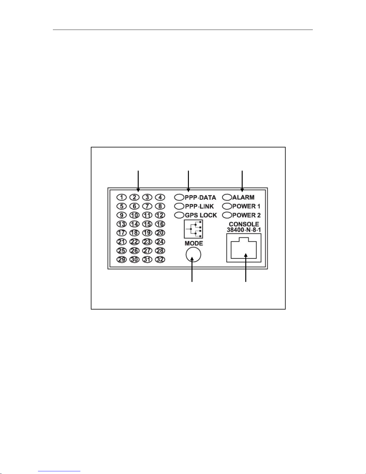
Console
Port
Push-Button
LAN/WAN Port
Status Indicators
PPP / GPS
Status Indicators
Device
Status Indicators
2 Panel Description
2.1 Display Panel Description
RX1000 series products are equipped with a versatile display panel, shown in Figure
1, which provides quick status information for each port, as well as for the entire
device, to allow simple diagnosis and troubleshooting. It features:
RS232 console port for „out of band‟ console access and configuration
Power supply and Alarm status indicators
Convenient port status indicators conveying link activity information
System reset via push-button if held for 5 seconds
Figure 1: LED Display Panel
RuggedRouter® RX1000 Family 9 RuggedCom® - Rev.122
Panel Description
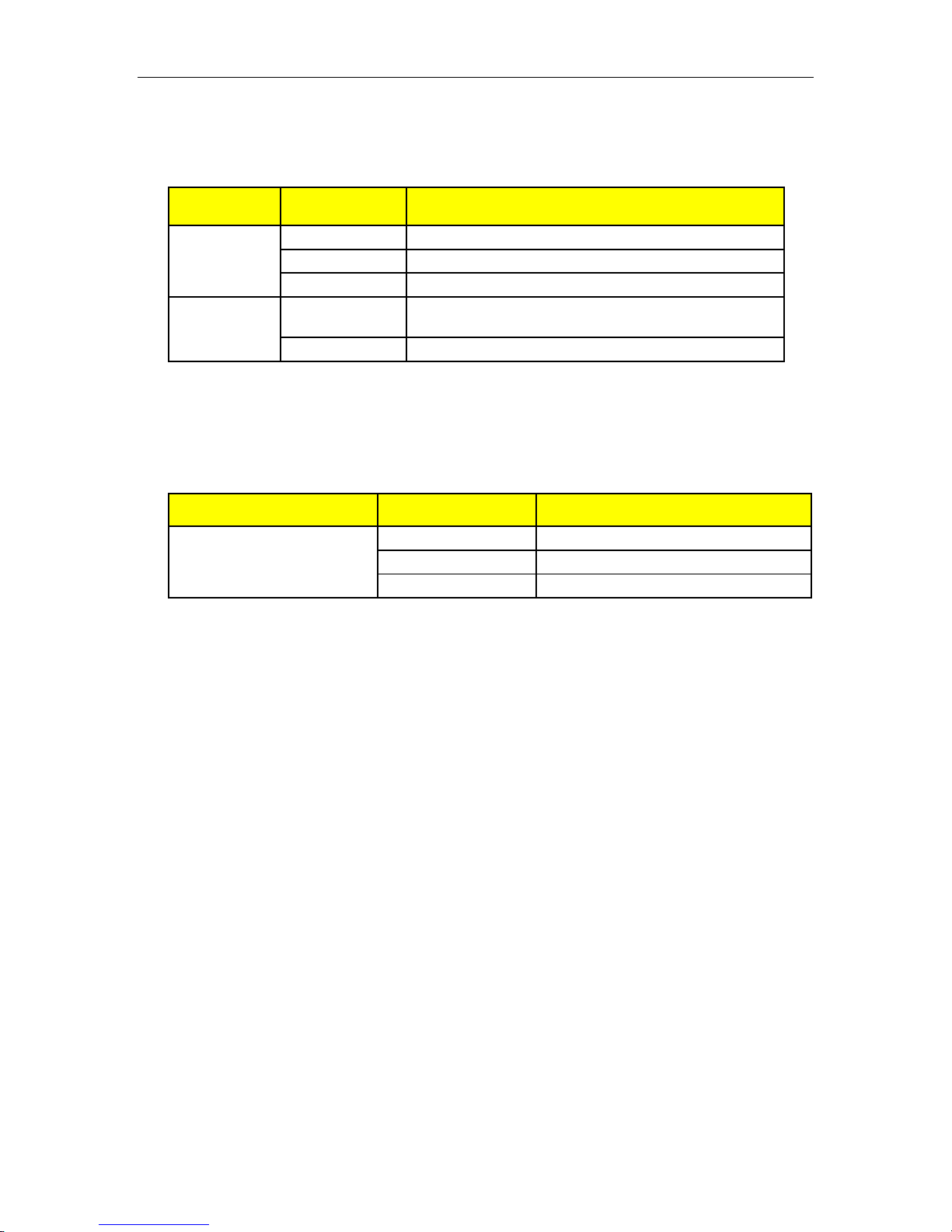
LED
Color
Description
PS1 / PS2
Green
Power supply operating normal
Red
Power supply failure
Off
No power supply installed
Alarm
Red
Alarm exists – log in to web management
interface to determine alarm code
Off
No alarms exist
Mode
Color
Description
Port Status Indicators
Green (Solid)
Link / Activity
Red
Error
Off
No link, or port not configured
Device status LEDs exist to provide a quick visual indication to operators for
operational status of the unit. Table 1 defines each possible LED color and its
corresponding description.
Table 1: LED Display – Device status LED behavior definition
The AN/WAN port status indicators as well as the dedicated PPP/GPS status
indicators provide a quick visual indication of the operational status of each function.
Although the behavior of each LED display will differ according to hardware, a
standard color scheme has been adopted and is show in Table 2.
Table 2: LED Display – Port Status behavior definition
RuggedCom® - Rev.122 10 RuggedRouter® RX1000 Family
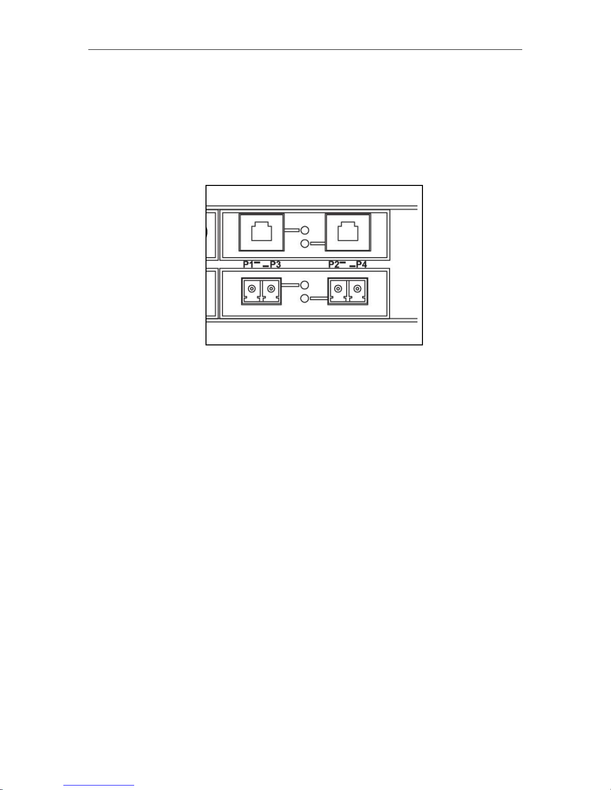
Panel Description
Port 1
Port 2
Port 3
Port 4
2.2 Ethernet Panel Description
Slots 3 and 4 of the RX1000 series can be populated with standard RuggedCom
dual-port Ethernet modules. Each Ethernet module is equipped with two LEDs that
indicate link/activity status information. The LED will be solid for ports with link, and
will blink for activity. The diagram in Figure 2 highlights each port and its associated
link/activity LED.
Figure 2: Ethernet panel LED description
RuggedRouter® RX1000 Family 11 RuggedCom® - Rev.122
Installation
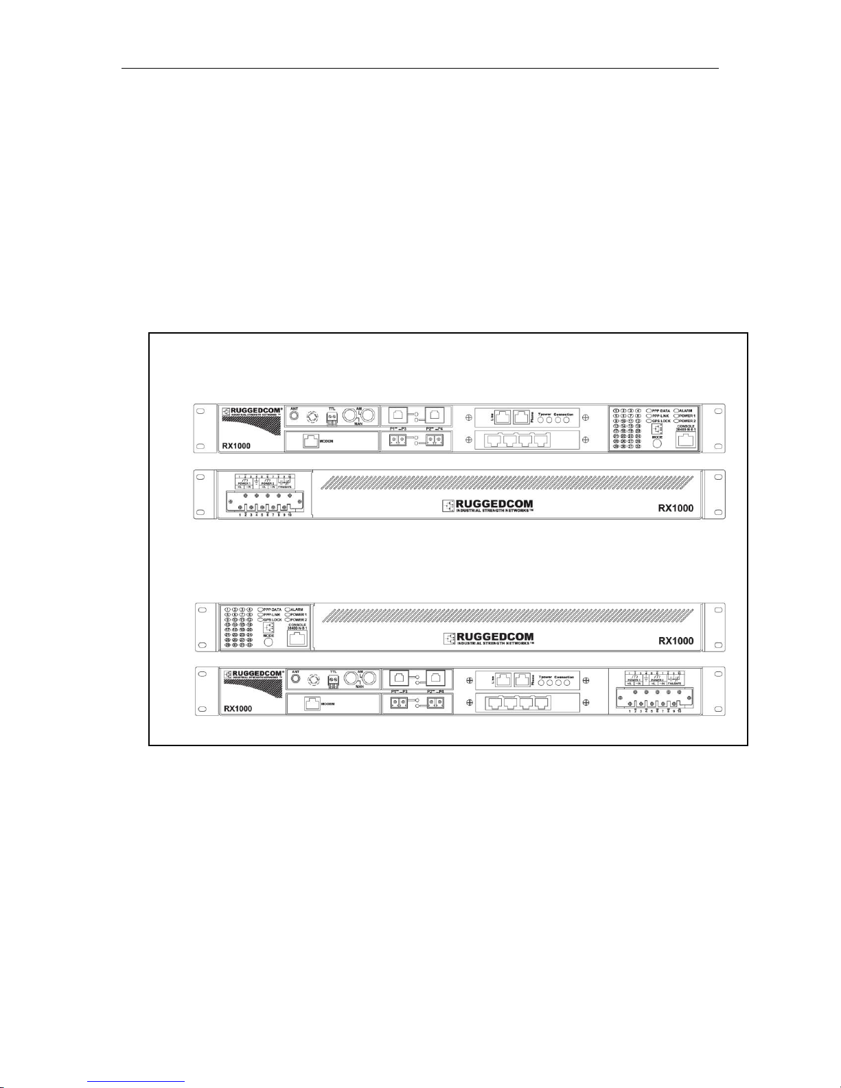
19” Rack mount I/O Connector Orientation Options
Front: LED Display and I/O Panels Rear: Power Terminal Block
Front: LED Display Rear: Power Terminal Block and I/O Panels
Front
Rear
Front
Rear
Front Mount
Rear Mount
3 Installation
3.1 Mounting
The RX1000 series has been designed with maximum mounting and display
flexibility. Customers can order an RX1000 series product that can be mounted in a
standard 19” rack, 1” DIN Rail, or directly onto a panel. For rack mount installations,
the RX1000 series can be ordered with connectors on the front of the unit, or can
located on the rear of the chassis to allow for all data and power cabling to be
installed and connected at the rear of the rack. See Figure 3 for examples of rack
mount orientation.
Figure 3: RX1000 Rack mount orientation options
RuggedCom® - Rev.122 12 RuggedRouter® RX1000 Family
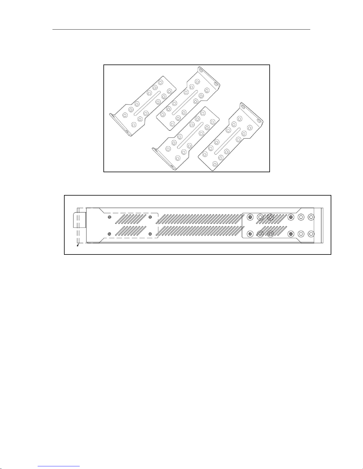
3.1.1 Rack Mounting
Figure 4: 19” Rack Mount Adapters
Installation
Figure 5: Rack mount adapter mounting location
The RX1000 series can be rack mounted using the included rack mount adapter
assemblies shown in Figure 4. Secure the rack mount adapter to the front side of the
chassis using the included black PAN head Phillips screws in the positions shown in
Figure 5. The entire chassis can then be mounted to a standard 19” rack. An
additional two rack mount adapters are included to optionally secure the rear of the
chassis in high-vibration, or seismically active locations.
NOTE: Since heat within the RX1000 is channeled to the enclosure, it is
recommended that 1 rack-unit of space (1.75”) be kept unpopulated and free of
equipment above each RX1000 series product to allow convectional airflow.
Although forced airflow is not necessary, any increase in airflow will result in a
reduction of ambient temperature that will improve long-term reliability of all
equipment mounted within the rack space.
RuggedRouter® RX1000 Family 13 RuggedCom® - Rev.122
Installation
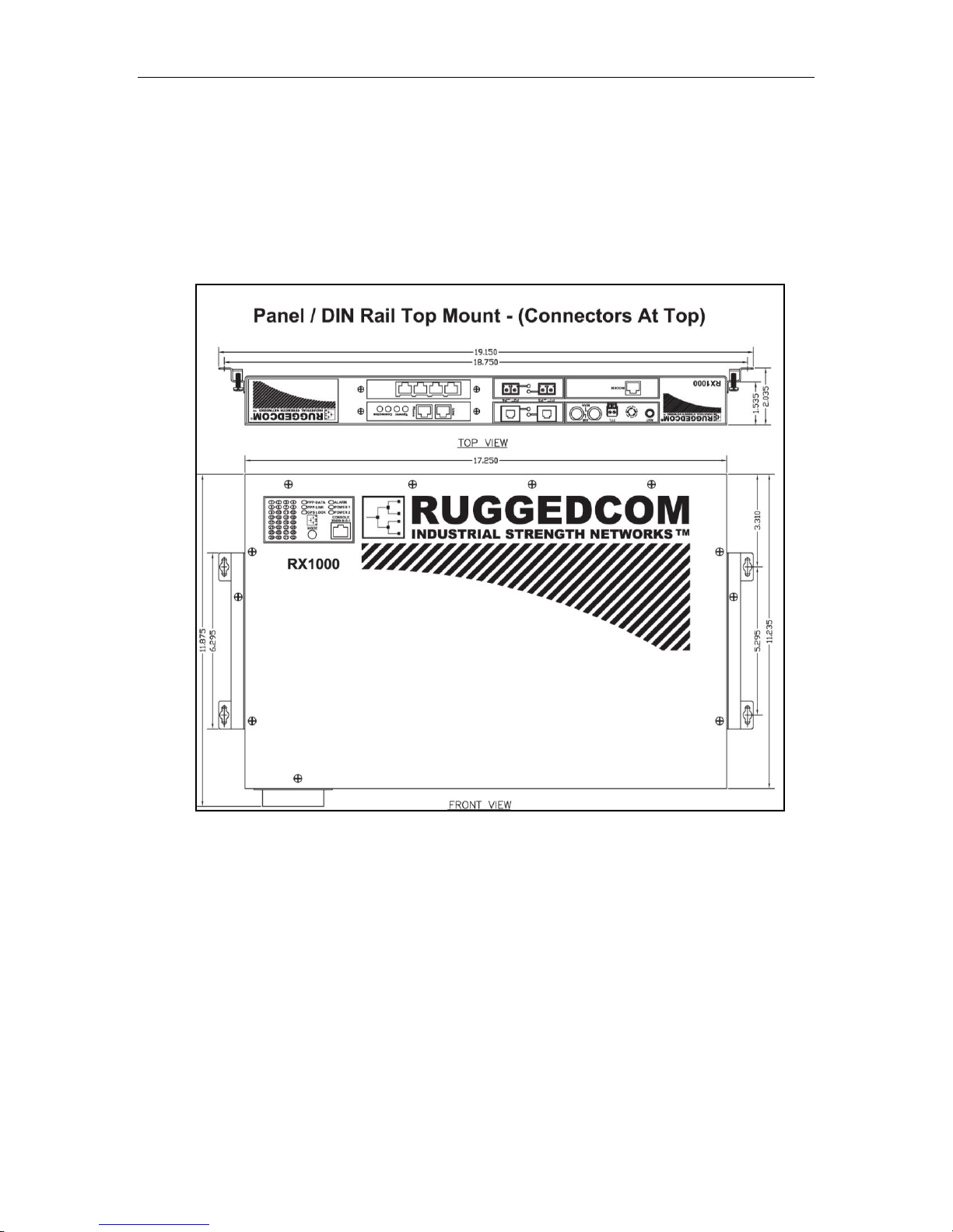
3.1.2 Panel and DIN Rail Mounting
RX1000 series products can be ordered as a Panel/DIN mount chassis. Both options
involve the use of the Panel/DIN adapters to be mounted on each side of the chassis
enclosure. The adapter allows the chassis to be mounted on the standard 1” DIN rail
using the grooves in the adapter, secured using the included Phillips screw. See
Figure 6 for a Panel/DIN mount diagram.
Figure 6: RX1000 Panel/DIN Rail mounting diagram
RuggedCom® - Rev.122 14 RuggedRouter® RX1000 Family
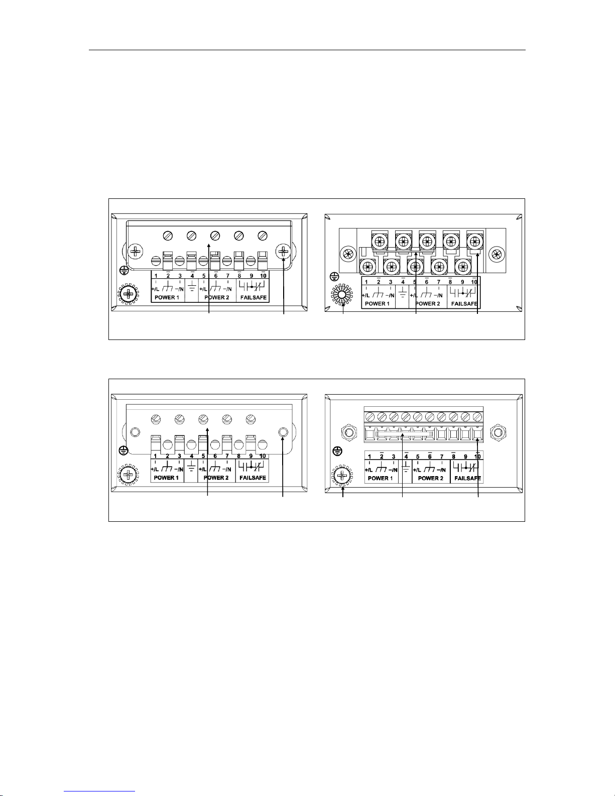
Installation
Philip s Scre w Term ina l w ithout C o v e rPhilip s Scre w Term ina l w ith C over
Safe ty C o v e r
Safe ty C o v e r
Scre ws
Ch a s sis Gro und
Co n n e c tio n
Surg e / C ha ssi s
G round J um per
Term inal
Phoen ix Plug T erm in a l w itho ut C overPhoen ix Plug T erm in a l w ith C over
Safe ty C o v e r
Scre ws
Safe ty C o v e r
Ch a ssis G round
Co n n e c tion
Term inal
Surg e / C ha ssis
G round J um p er
3.2 Power Supply Wiring and Grounding
RX1000 and RX1100 support dual redundant universal high voltage range power
supplies: “Power Supply 1 (PS1)” and “Power Supply 2 (PS2)”. RX1000P and
RX1100P feature a universal high voltage range power supply as PS1, and a
separate 48VDC supply, PS2, to provide Power over Ethernet. The connections for
PS1, PS2 and the fail-safe relay are located on the terminal block as shown in Figure
7 and Figure 8.
Figure 7: RX1000 Series Phillips Screw Terminal Block
Figure 8: RX1000 Series Phoenix Plug Terminal Block
The RX1000 Family chassis ground connection, shown in Figure 9, uses a #6-32
screw. It is recommended to terminate the ground connection in a #6 ring lug, and to
use a torque setting not exceeding 15 in.lbs (1.7 Nm).
RuggedRouter® RX1000 Family 15 RuggedCom® - Rev.122
 Loading...