

GB
OWNERS MANUAL - Powered Lawnmowers - Walk Behind
Model Nos. 51, 61 & 80
D
GEBRAUCHSANWEISUNG - Motor-Rasenmäher -
Modell Nr. 51, 61 & 80
F
MANUEL DU PROPRIETAIRE - Tondeuse à Gazon à Essence -
Modèles 51, 61 & 80
SP
MANUAL DEL PROPIETARIO - Cortadoras de Césped a Gasolina -
Modelos 51, 61 & 80
NL
HANDLEIDING - Benzine Grasmaaimachine -
Types 51, 61 & 80
1
MANUALE INSTRUZIONI - Falciatrice A Motore -
Modelli. 51, 61 & 80
™
TM
Powered Walk Behind Mower - CE Part No. 04016218 Rev G © Copyright 12/2006
™
•Wear eye protection
•Augenschutz tragen
•Porter des lunettes de protection
•Proteja sus ojos
•Gebruik oogbescherming
•Indossare occhiali di protezione
•Engage - switch, lever or position
•Einrücken - Schalter, Hebel oder Stellung
•Interrupteur, Levier ou Position d’embrayage
•Accionar - interruptor, palanca o posición
•Inschakelen - Schakelaar, Heftboom of positie
•Innesto - interruttore, leva o posizione
•Push handle to handle bar to drive mower forward
•Zum Losfahren den Bremsgriff zur Lenkstrange drücken
•Pousser la poignée vers l’avant pour utiliser la tondeuse en
marche avant
•Empuje la manigueta hacia el manubrio para que el cortacésped
avance
•Breng de duwhendel naar het stuur om de grasmaaier in
beweging te zetten
•Spingere l’impugnatura verso il manubrio per far avanzare la
falciatrice
•Slow speed
•Niedrige Drehzahl
•Position lente
•Lento
•Langzaam
•Bassa velocità
•Fast speed
•Hohe Drehzahl
•Position rapide
•Rápido
•Grote snelheid
•Alta velocità
•Off - switch, lever or position
•Ausschalten- Schalter, Hebel oder Stellung
•Arrêt - Interrupteur, Levier ou Position
•Apagado - interruptor, palanca o posición
•Af-schakelaar, Heftboom of positie
•Arresto - interruttore, leva o posizione
•On or start - switch, lever or position
•
Einschalten bzw. starten - Schalter, Hebel oder Stellung
•Marche - Interrupteur, Levier ou Position
•Activado o Arranque - interruptor, palanca o posición
•Aan-schakelaar, Heftboom of positie
•Marcia - interruttore, leva o posizione
•Keep hands and feet away
•Hände und Füße fernhalten
•Garder les mains et les pieds á distance
•Mantenga manos y pies alejados
•Handen en voeten weghouden
•Tenere lontani mani e piedi
•Rotating blades in cutterhead
•Laufende Messer im Schneidkopf
•Lames tournantes dans la tête de coupe
•Cuchillas giratorias en el cabezal portacuchilla
•Draaiende snijmessen in snijkop
•Lame rotanti nella testa della trancia
ii
•Engine choke
•Choke
•Starter
•Obturador del motor
•Machineklep
•Valvola dell’aria del
motore
•Caution
•Vorsicht
•Précaution
•Precaución
•Voorzichtig
•Attenzione
•Refer to the owners manual
•Siehe Handbuch
•Se référer au manuel
•Consulte el manual del
propietario
•Lees het Eigenaar’s Handboek
•Consultare il manuale delle
istruzioni
•Disengage - switch, lever or position
•Lösen - Schalter, Hebel oder Stellung
•Interrupteur, Levier ou Position de débrayage
•Desembrague - interruptor, palanca o posición
•Uitschakelen - Schakelaar, Heftboom of positie
•Disinnesto - interruttore, leva o posizione
•Thrown objects, keep clear
•Fremdkörper werden
ausgeworfen - Abstand halten!
•Projectiles – ne pas s’approcher
•No se acerque - objetos son
lanzados
•Vliegende voorwerpen, uit de
weg blijven
•Oggetti proiettati, non avvicinarsi
•Caution rotating blades while doing maintenance
•Achtung - Messer laufen während Wartung weiter
•Précaution, lames tournantes pendant l’entretien
•Precaución con las cuchillas giratorias durante el mantenimiento
•Voorzichtig met draaiende snijmessen bij onderhouden van
•Attenzione alle lame rotanti durante la manutenzione
•Blades free wheel to a stop
•Messer laufen bis zum Stillstand aus
•Le débrayage des lames arrête la roue
•El plato de cuchillas debe parar
por sí misma
•Snijmessen draaien door tot ze stoppen
•Ruota di ingranaggio delle lame in
arresto
•Remove spark plug wire
•Zündkabel abziehen
•Enlever le fil de la bougie
•Quite el cable de la bujía
•Bougie kabel ontkoppelen
•Rimuovere il cavo di accensione
•Keep bystanders clear
•Personen vom Gerät fernhalten
•Ne laisser approcher personne
•Mantenga a las personas lejos
•Toeschouwers uit de weg houden
•Non fare avvicinare nessuno
•Disconnect electrical cable
•Netzstecker ziehen
•Débrancher le fil électrique
•Desconecte el cable eléctrico
•Elektrische kabel uitschakelen
•Sconnettere il cavo elettrico
•Refer to the owners manual for
maintenance details
•Siehe Handbuch für Wartungsdetails
•Se référer au manuel pour les détails
d’entretien
•Consulte la información sobre
mantenimiento en el manual del
propietario
•Voor onderhoud details lees het
Eigenaar’s Handboek
•Consultare il manuale delle istruzioni
per dettagli sulla manutenzione
•Push handle forward to release blade brake & vice versa
•Zum Lösen der Messerbremse den Griff nach vorne schieben, zum
Anziehen der Bremse den Hebel wieder nach hinten ziehen
•Pousser la poignée vers l’avant pour desserrer le frein des lames, et
vice-versa
•Mueva la manigueta hacia adelante para desactivar el freno de las
cuchillas y viceversa
•Duw de hendel naar voren om de snijmesriem te ontkoppelen en
omgekeerd
•Spingere l’impugnatura in avanti per rilasciare il freno delle lame e
viceversa
•Wear foot protection
•Fußschutz tragen
•Porter des chaussures
•Proteja sus pies
•Gebruik Voetbescherming
•Indossare calzature
•Wear hand protection
•Handschutz tragen
•Porter des gants
•Proteja sus manos
•Gebruik handbescherming
•Indossare dei guant
•Wear hearing protection
•Gehörschutz tragen
•Porter un protecteur acoustique
•Proteja sus oídos
•Gebruik gehoor bescherming
•Indossare protezione acustica
• Symbols are used on the machine to communicate important information.
• A list of symbols and their meanings are shown below.
• Please familiarise yourself with them before operating the machine.
• Die Symbole auf dem Gerät vermitteln wichtige Hinweise zum Betrieb.
•Weiter unten finden Sie eine Liste aller Symbole mit deren Erläuterungen.
• Bitte machen Sie sich vor der Inbetriebnahme mit ihnen vertraut.
• Communication d’informations importantes sur l’appareil au moyen de
symboles.
• Ci-dessous, liste des symboles assortie der leur signification.
• Veuillez vous familiariser avec ces symboles avant la mise en marche de
lappareil.
GB
D
F
• Los símbolos de la máquina brindan información muy importante.
• La lista de símbolos y significados están indicados abajo.
• Familiarícese con los símbolos antes de poner en marcha la máquina.
• Symbolen op de machine geplaatst geven belangrijke informaties.
• Een lijst van symbolen en hun betekenissen hierbij volgt.
• U moet zich met deze symbolen bekendmaken voordat U de machine in werking stelt.
• I simboli vengono utilizzati sulla macchina per comunicare informazioni importanti.
• Una lista dei simboli e dei loro significati è riportata sotto.
• Siete pregati di acquisire familiarità con questi simboli prima dell’utilizzo della
macchina.
SP
NL
1
Powered Walk Behind Mower - CE Part No. 04016218 Rev G © Copyright 12/2006

PREFACE
Congratulations on your purchase of a quality Australian made and designed product from an Australian owned company.
This manual covers the operation and maintenance of the Rover Walk Behind Powered Lawn Mowers, as listed on the front cover of this manual.
Please read and understand this and any associated manual before using this machine. If any point is unclear, please contact any
authorised Rover service dealer.
WARNING
Symbols
The following symbols have been used in this manual to highlight important information:
This symbol warns against injury to the operator or bystanders.
WARNING
This symbol warns against mower damage or possible loss of warranty.
CAUTION
This symbol highlights good ideas or tips.
LABELS ......................................................................................ii
PREFACE ....................................................................................iii
SAFETY INSTRUCTIONS..........................................................1
COMPONENTS.........................................................................2
SPECIFICATIONS.......................................................................2
SETTING UP..............................................................................2
Assembly of the Grass Catcher
Folding the Handle
Adjusting the Handle Height
Removing the Packaging Ties from the Control Handles
Engine Lubrication and Fuel
Powerstart Option
Self Propelled Option
OPERATION..............................................................................3
Grass Catcher
- Installing the Grass Catcher
- Removing the Grass Catcher
Mulch Plug
Grass Deflector
Adjusting the Cut Height
Engine
- Starting the Engine
- Stopping the Engine
Grass Cutting and Catching
Self Propelled Option
- Using the Self Propelled Transmission
MAINTENANCE........................................................................5
General Cleaning
- Cleaning the Underside of the Mower
- Cleaning the Upperside of the Mower
Changing the Cutting Blades
Self Propelled Option
- Adjusting the Drive Cable
- Removing the Drive Frame Cover
- Replacing the Drive Frame Cover
- Drive Chain Lubrication
- Drive Chain Adjustment
- Drive Belt Adjustment
- Drive Belt Replacement
- Adjusting the Drive Clutches
- Lubricating the Drive Pawls
Powerstart Option
TROUBLE SHOOTING .............................................................12
General
Powerstart Option
Self Propelled Option
SPARE PARTS VIEWS................................................................14
Base Spare Parts
Handlebar Spare Parts
Self Propelled Spare Parts
Ancillary Spare Parts
iii
TABLE OF CONTENTS
ENGLISH
™
Powered Walk Behind Mower - CE Part No. 04016218 Rev G © Copyright 12/2006

1
ENGLISH
SAFETY INSTRUCTIONS
TRAINING
• Read the instructions carefully. Be familiar with the controls and the proper use of the equipment.
• Never allow children or people unfamiliar with these instructions to use the mower. Local regulations may restrict the
age of the operator.
• Never mow while people, especially children, or pets are nearby.
• Keep in mind that the operator or user is responsible for accidents or hazards occurring to other people or their property.
PREPARATION
• While mowing, always wear substantial footwear and long trousers. Do not operate the equipment when barefoot or
wearing open sandals.
• Thoroughly inspect the area where the equipment is to be used and remove all stones, sticks, wires, bones and other
foreign objects.
• WARNING - Petrol is highly flammable. Take the following precautions:
- Store fuel in containers specially designed for this purpose.
- Refuel outdoors only and do not smoke while refuelling.
- Add fuel before starting the engine. Never remove the cap of the fuel tank or add petrol while the engine is running
or when the engine is hot.
- If petrol is spilled, do not attempt to start the engine but move the machine away from the area of spillage and avoid
creating any source of ignition until petrol vapours have dissipated.
- For reasons of safety the petrol tank and tank cap lock must be replaced if damaged.
• Replace faulty silencers.
• Before using, always visually inspect to see that the blades, blade bolts and cutter assembly are not worn or damaged.
Replace worn or damaged blades in sets to preserve balance.
• On multibladed machines, take care as rotating one blade can cause other blades to rotate.
OPERATION
• Do not operate the engine in a confined space where dangerous carbon monoxide fumes can collect.
• Mow only in daylight or in good artificial light.
• Avoid operating the equipment in wet grass, where feasible.
• Always be sure of your footing on slopes.
• Walk, never run.
• For wheeled rotary machines, mow across the face of slopes, never up and down.
• Exercise extreme caution when changing direction on slopes.
• Do not mow excessively steep slopes.
• Use extreme caution when reversing or pulling the mower towards you.
• Stop the blade(s) if the mower has to be tilted for transportation when crossing sur faces other than grass and when
transporting the mower to and from the area to be mowed.
• Never operate the mower with defective guards or shields, or without safety devices, for example deflectors and/or grass
catchers in place.
• Do not change the engine governor settings or overspeed the engine.
• Disengage all blade and drive clutches before starting the engine.
• Start the engine or switch on the mower carefully according to instructions and with feet well away from the blade(s).
• Do not tilt when starting the engine or switching on the motor, unless the mower has to be tilted for starting. In this case,
do not tilt it more than absolutely necessary and lift only the part which is away from the operator.
• Do not start the engine when standing in front of the discharge chute.
• Do not put hands or feet near or under rotating parts. Keep clear of the discharge opening at all times.
• Never pick up or carry a mower while the engine is running.
• Stop the engine and disconnect the spark plug lead:
- Before clearing blockages or unclogging the chute.
- Before checking, cleaning or working on the mower.
- After striking a foreign object. Inspect the mower for damage and make repairs before restarting and operating the
mower.
- If the mower starts to vibrate abnormally check immediately.
• Stop the engine:
- Whenever you leave the mower.
- Before refuelling.
• Reduce the throttle setting during engine run-out and if the engine is provided with a shut-off valve, turn off the fuel
at the conclusion of mowing.
MAINTENANCE AND STORAGE
• Keep all nuts, bolts, and screws tight to be sure the equipment is in safe working condition.
• Never store the equipment with petrol in the tank inside a building where fumes may reach an open flame or spark.
• Allow the engine to cool before storing in any enclosure.
• To reduce the fire hazard, keep the engine, silencer, battery compartment and petrol storage area free of grass, leaves,
or excessive grease.
• Check the grass catcher frequently for wear or deterioration.
• Replace worn or damaged parts for safety.
• If the fuel tank has to be drained, do this outdoors.
WARNING
™
Powered Walk Behind Mower - CE Part No. 04016218 Rev G © Copyright 12/2006
™
2
ENGLISH
SPECIFICATIONS
This manual covers several mowers with the following specifications:
- Models 51, 61
- 20” (508mm Cut Width)
- 12 Cut Height Settings
- Model 80
- 22” (560mm Cut Width)
- 15 Cut Height Settings
NB.
- Models come with one of a range of engines (refer to the engine manual included in the kit)
- Options are available (and may be included) on the above models e.g.
- Mulch Mowing
- Deflector Mowing
- Remote Air Cleaner
- Powerstart Function
- Self Propelled Function
- etc.
- Details may be included in this manual or on a separate manual included in the Mower Kit.
SETTING UP
Before using the Mower the following set-ups are required:
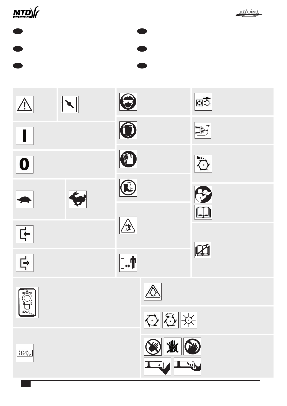
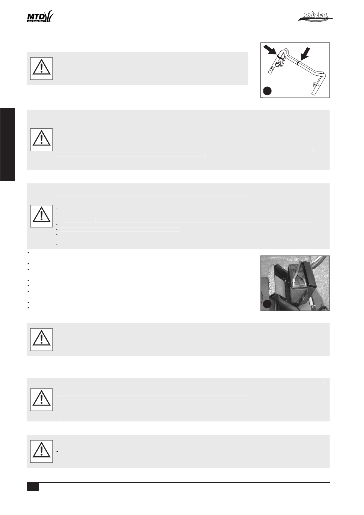
ASSEMBLY OF THE GRASS CATCHER
Locate the catcher handle and align its front lugs with the slots in the top of the catcher and press firmly into position
(refer figure 2).
Position the catcher top over the catcher bottom, aligning the barbs on the top with the slots in the bottom (refer
figure 2).
Press firmly down on the catcher top to lock the barbs into slots (refer figure 2).
Secure the top and bottom halves of the grass catcher together at the front using the two 3/16” screws, washers and
nyloc nuts supplied. Insert the screws from the outside with the washers and nyloc nuts on the inside of the catcher.
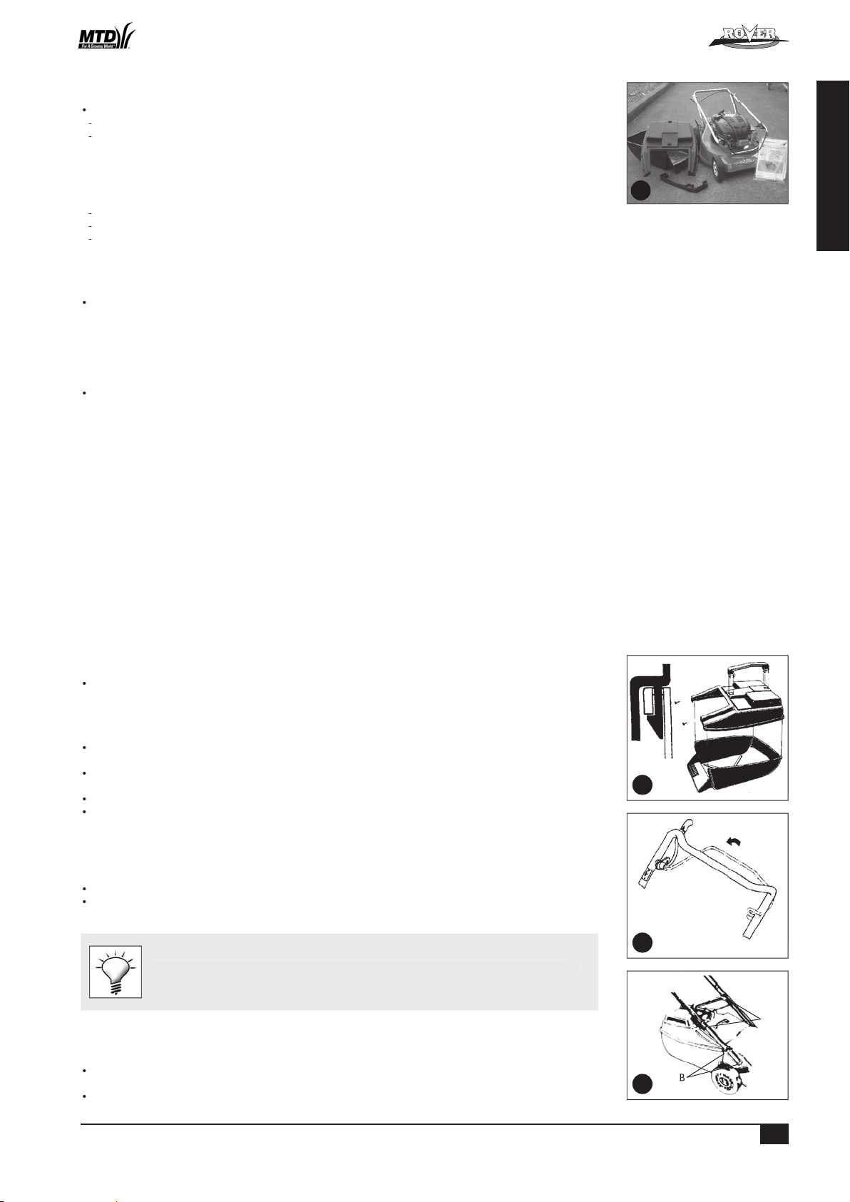
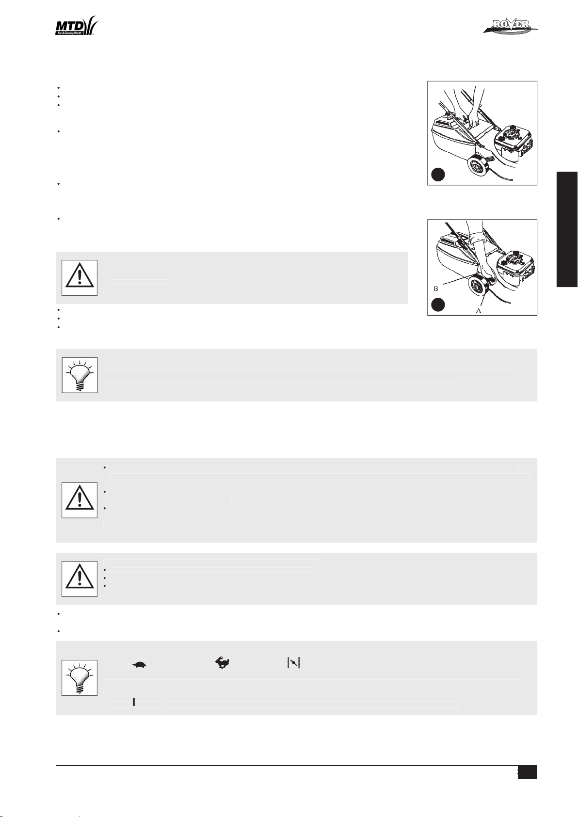
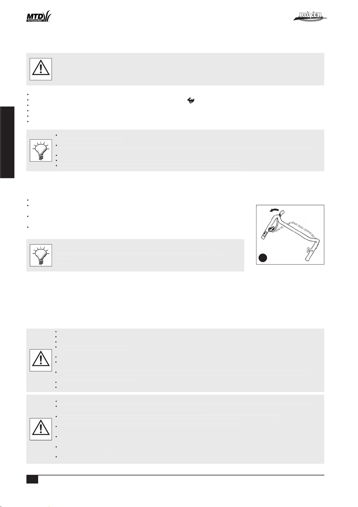
FOLDING THE HANDLE
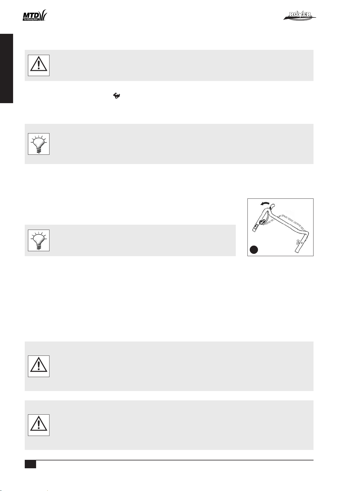
Locking knobs: by turning these knobs the handle bars can be either locked in the operating position or folded for storage.
Locking lever: lift the lever to release the handle bars for folding or push the lever closed to lock handle bars in the
operating position. Adjust the tension by turning the lock nut with a 1/2" AF spanner (refer figure 4 A).
Before unfolding the handlebar, ensure the throttle control is in the stopped position (see
“Starting the Engine” section) and activate the operator presence control lever (refer figure
3). Lift the handlebar slowly (as the engine start cord is attached and it will crank the engine)
until the fully erect position is achieved.
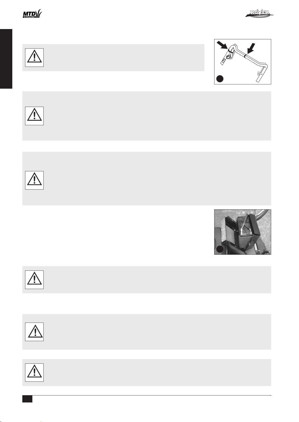
ADJUSTING THE HANDLE HEIGHT
Loosen the two nuts (B) at the base of the handle bars on both sides of the mower using a 1/2" AF spanner (refer figure
4).
Move the handle bars to the required position and tighten the handle bar nuts.
COMPONENTS
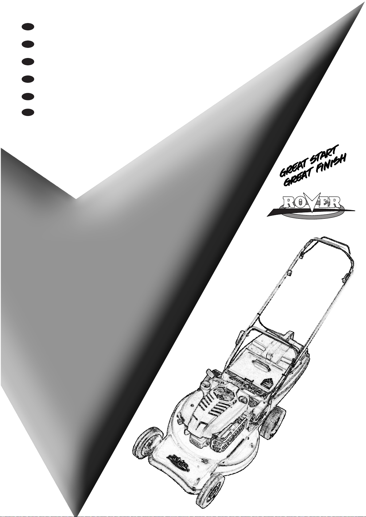
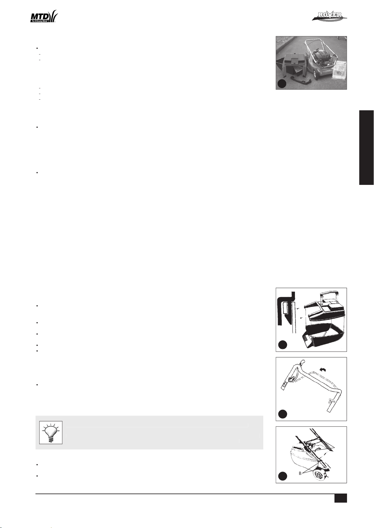
Ensure that all the following component parts are included in the package (refer figure 1):
Mower (1 off)
Kit including:
Owners Manual (1 of)
Engine Manual (1 of)
Spark Plug Spanner (1 of)
Screw - 3/16” x 1/2” UNC (2 of)
Nyloc nut - 3/16” UNC (2 of)
Washer - 3/16” x 1/2” flat (2 of)
Grass catcher bottom (1 of)
Grass catcher top (1 of)
Grass catcher handle (1 of - may be loose or fitted to Grass catcher top)
NB. Other accessories may be included in the carton which vary with each model. These items will be covered by a
separate owners manual e.g. Mulch Mowing Kit, Grass Deflector Kit, etc.
Notify the place of purchase of missing items as soon as possible.
1
2
4
B
3
Powered Walk Behind Mower - CE Part No. 04016218 Rev G © Copyright 12/2006
3
ENGLISH
SETTING UP (Continued)
REMOVING THE PACKAGING TIES FROM THE CONTROL HANDLES
Remove and discard the packaging ties clamping the blade brake and self propelled drive
control bale to the handle bar before attempting to start the mower (refer figure 5).
WARNING
• Unfold the handlebars and lock in the erect position (refer to the “Folding the Handlebar” section).
• Remove the packaging ties (refer figure 5).
ENGINE LUBRICATION AND FUEL
The engine safety precautions, oil and fuel recommendations, operation instructions, adjustments and maintenance is covered in the
engine manufacturer’s manual which is included in the mower kit. Please refer to and adhere to these recommendations.
If you do not have the engine manufacturer’s manual please refer to the nearest engine
manufacturer’s representative for a replacement copy.
The engine is packed without oil or fuel. Please add these as per the engine manufacturer’s recommendations before attempting
to start the engine.
Do not allow any dirt or contaminants to enter the fuel tank or oil filler tube.
CAUTION
POWERSTART OPTION
The battery must be removed from the mower while recharging.
Only use the battery charger indoors where it cannot be af fected by weather.
The battery contains a strong acid electrolyte which may cause personal and material damage.
- Do not dissassemble, drop or damage the battery.
- Do not incinerate or expose the battery to high heat or a flame or it may explode.
- Dispose of batteries thoughtfully. Refer to your local regulations for battery disposal.
- Replace any leaking battery immediately.
- Clean the battery only with a dry cloth - never use petrol, thinners or other petrochemical.
- Neutralize any electrolyte spills with an alkaline solution.
WARNING
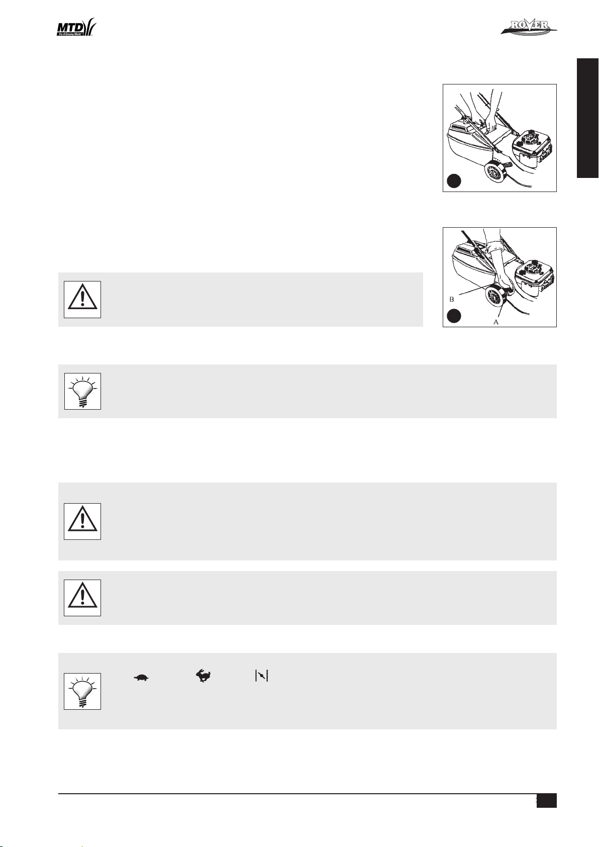
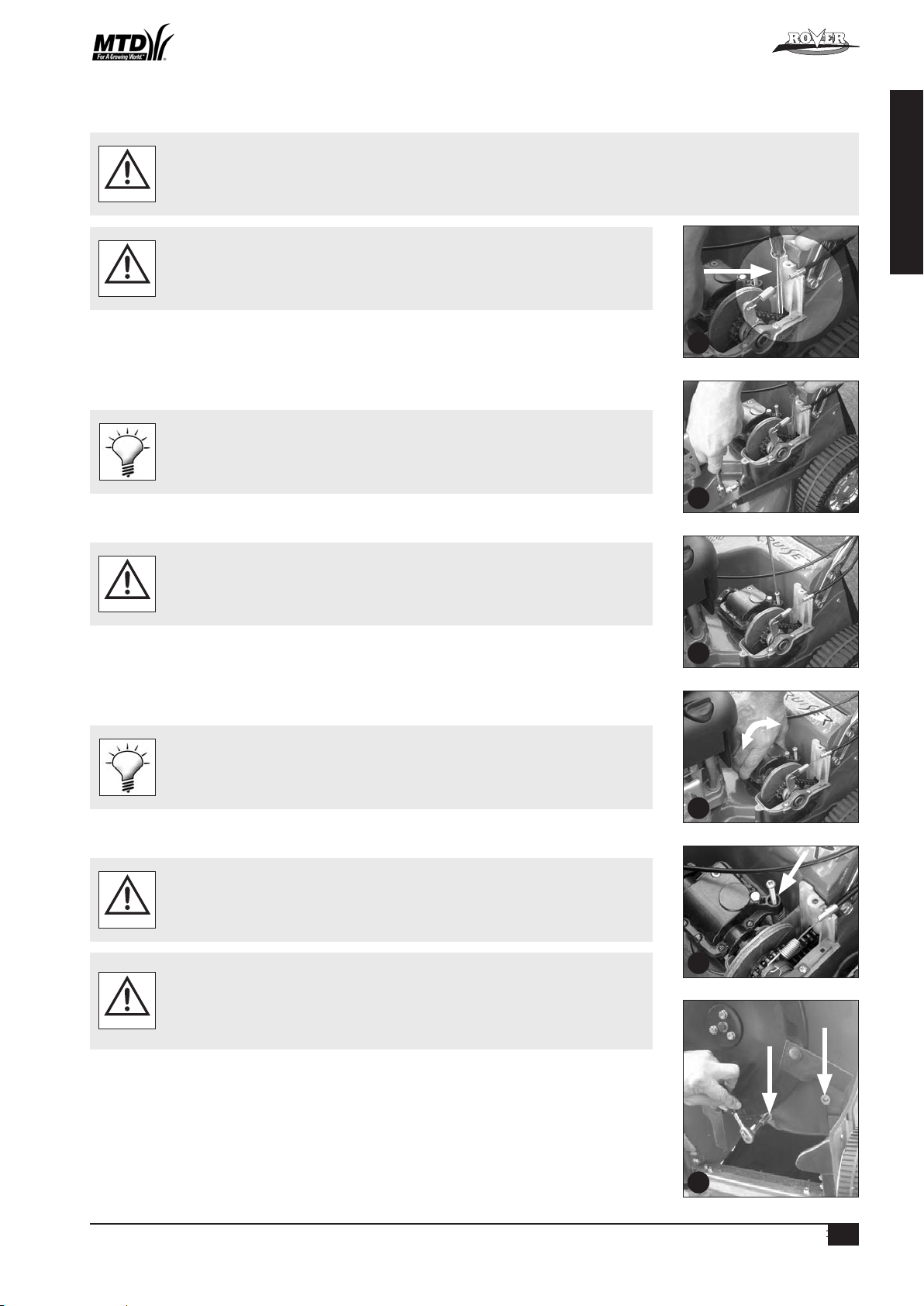
• Remove the two screws from the battery support box, rotate the battery and lid forward and expose the battery
terminals (refer figure 6).
• Slide the red and black wire from the battery terminals and remove the battery.
• Place the battery in a dry, cool area and connect the battery charger cables to the battery terminals (red [+] to red
[+] and black [-] to black [-]).
• Connect the battery charger to a 220-240 volt power outlet and switch it on.
• Allow to charge for 10-16 hours, switch the 220-240 volt power outlet off and remove the battery charger cables from the
battery.
• Refit the rubber battery blocks to each end of the battery and refit into the battery support box.
• Slide the wiring loom connections onto the battery terminals red [+] to red [+] and black [-] to black [-].
• Locate the battery support box lid, refit and tighten the two screws.
SELF PROPELLED OPTION
Remove and discard the packaging tie clamping the self propelled drive control bale to the handle bar before attempting to start
the mower (refer figure 5).
WARNING
OPERATION
• Refer to and follow the “Safety Instructions” in this and any other associated manuals supplied with this product before attempting
to operate this machine.
• Refer to and understand the safety symbols fitted to the machine and shown in the “Labels” section of this manual.
• Ensure that all the items in the “Setting Up” section have been completed.
• Ensure that the “Operator Presence Control” functions correctly. This control is a mandatory safety item and operates a brake on
the engine. When the lever is held against the handlebar the brake is released and the blades/engine are free to rotate. When the
lever is released the brake is applied and the blades/engine brake quickly to a stop
WARNING
GRASS CATCHER
• Never install or remove the Grass catcher with the engine running.
WARNING
6
5
™
Powered Walk Behind Mower - CE Part No. 04016218 Rev G © Copyright 12/2006
4
ENGLISH
OPERATION (Continued)
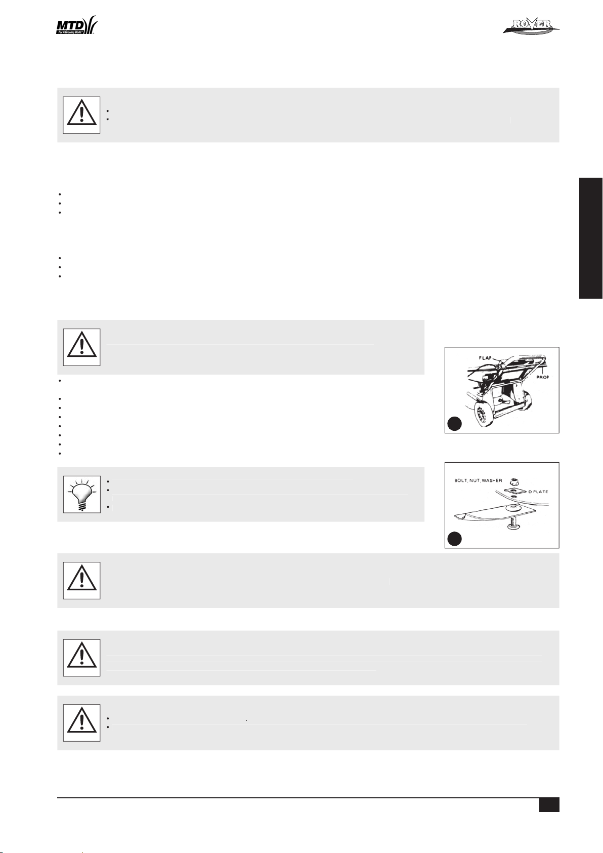
Installing the Grass catcher
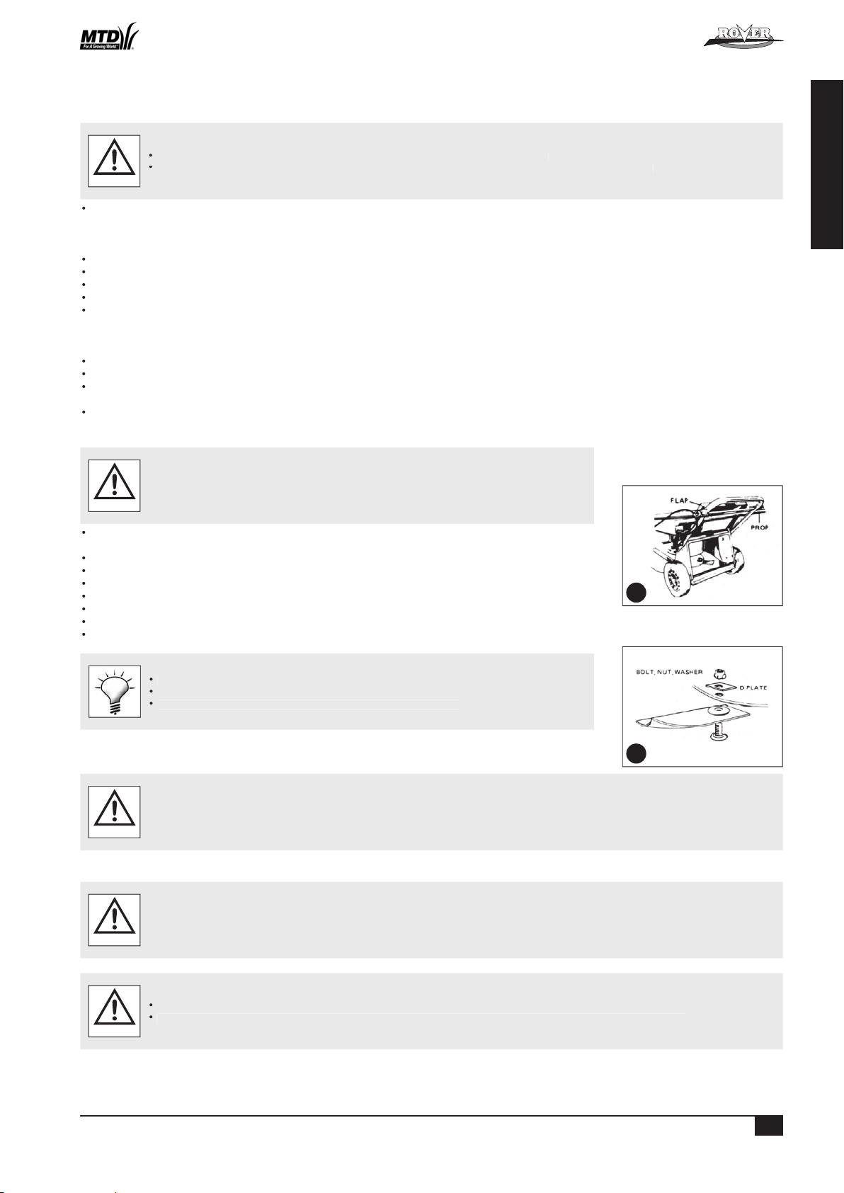
• Raise the rear flap of the mower.
• Grasp the grass catcher by the top handle and position the grass catcher against the rear of the mower (refer figure 7).
• Lower the rear flap so that the back edge of the flap hooks over the matching lip on the grass catcher.
Removing the Grass catcher
• Grasp the grass catcher top handle and lift up.
• Raise the rear flap of the mower to release grass catcher.
• Lift the grass catcher clear of the mower and lower the rear flap.
MULCH PLUG
• Refer to the separate Mulch ‘n’ Catch Owners Manual.
GRASS DEFLECTOR
• Refer to the separate Grass Deflector Owners Manual.
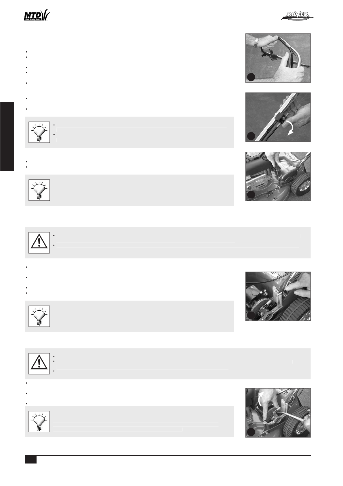
ADJUSTING THE CUT HEIGHT
• When setting the cut height stand to the rear of the machine with your feet well clear of
the cutting blades.
WARNING
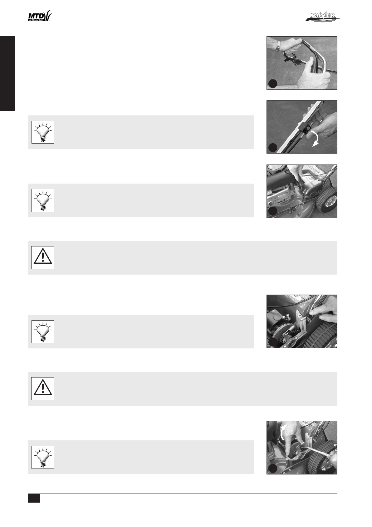
• Grasp the height of cut lever (A) and apply an outward pressure to release the lever from the rack (B) (refer figure 8).
• Move the lever (while holding out) to the required height of cut position and engage the lever in the rack.
• Pushing the lever forward and down raises the cut height and vice versa.
It is advisable to start the mower in the high cut position and gradually drop the height notch by notch until the desired height is
achieved. Starting too low will leave a low spot in the lawn.
ENGINE
NOTE: The mowers covered in this manual have various engine types from various manufacturers. Included in the Mower Kit is an engine manual specific to each mower
which provides the details for the engine’s operation. Please refer to the engine manufacturer’s manual for precise instructions.
Starting the Engine
• The engine safety precautions, oil and fuel recommendations, operation instructions, adjustments and maintenance is covered in the
engine manufacturer’s manual which is included in the mower kit. Please refer to and adhere to these recommendations.
• If you do not have the engine manufacturer’s manual please refer to the nearest engine manufacturer’s representative for a
replacement copy.
• The engine is packed without oil or fuel. Please add these as per the engine manufacturer’s recommendations before attempting
to start the engine.
• If fitted with the Powerstart option activate the operator presence control lever (to release the blade brake) before attempting
to crank the engine.
CAUTION
• Refer to the “Warning” notes at the beginning of the “Operation” section.
• Start the mower on a clear level surface.
• Keep your fingers, toes and bystanders clear when starting or operating the engine.
• If fitted with the Powerstart option, always remove the key from the ignition switch and keep in a safe place to prevent unauthorised
cranking of the engine.
WARNING
• Refer to the engine manufacturer’s manual for the starting procedure, remembering to activate the operator presence control lever before cranking the engine.
• If fitted with the Powerstart option, insert the key into the ignition switch then follow the instructions in the engine manufacturer’s manual.
The Rover throttle control uses symbols to indicate the throttle function at various throttle positions:
O (off), (slow speed), (fast speed), (engine choke)
These positions align with settings required in the engine manufacturer’s manual.
The Rover Powerstart option can be started with an ignition key which is fitted to the handle bar. The switch plate uses symbols to
indicate the key function at various positions and refers to the state of the starter motor:
O (off), I (on/star t). These positions align with the settings required in the engine manufacturer’s manual.
Stopping the Engine
• Refer to the engine manufacturer’s manual for stopping procedure.
• If fitted with the Powerstart option remove the ignition key and store in a safe place after use.
7
8
™
Powered Walk Behind Mower - CE Part No. 04016218 Rev G © Copyright 12/2006
5
ENGLISH
OPERATION (Continued)
GRASS CUTTING AND CATCHING
Refer to and abide to the instructions noted in the safety instructions of this and associated manuals.
WARNING
• Fit the Grass catcher to the mower (refer to the “Setting Up” section).
• Start the engine and set the engine speed to fast ( ) on the throttle control.
• Set the desired cut height (refer to “Setting the Cut Height” above).
• Drive the mower forward through the grass until the catcher fills.
• Stop the engine, remove and empty the catcher.
• Repeat the process.
• To maximise the cutting and catching performance it is important to maintain high engine speed, so adjust the mower ground
speed to suit.
• If the grass length or density is excessive (to maintain high engine speed initially) cut the grass at a higher setting, then at the
desired height.
• Replace blades regularly to maintain a sharp cutting edge.
• Keep the mesh in the grass catcher clean to allow the grass catcher to fill properly.
• Keep the underside of the mower deck clean and free of clipping build-up.
SELF PROPELLED OPTION
Using the Self Propelled Transmission
• Start the engine and set the engine speed to fast.
• Push forward on the clutch engagement lever to engage the self-propelled drive to the rear wheels noting that the drive
speed increases as you move the bale closer to the handle bar (refer figure 9).
• Hold the bale at the required drive speed and slow down or speed up as the conditions dictate.
• To disengage the self-propelled drive release the engagement lever and allow it to return to the disengaged position.
Release the self-propelled drive bale and push the machine when changing direction or mowing
in a confined area for safety.
MAINTENANCE
NOTE: The majority of mower problems involve the following problems:
- Dirt or contaminants in the fuel
- Incorrect oil level in the engine
- Blocked, damaged or incorrectly fitted air cleaner
- Incorrectly maintained blades
(Refer to the maintenance section of this and the engine manufacturer’s manual for details.)
• Always ensure equipment is in good working order.
• Do not use any equipment with worn or damaged components.
• Always use genuine Rover replacement parts.
• Never attempt maintenance that is not outlined in this manual. Refer to your nearest authorised Rover Service Dealer.
• Always ensure the engine is stopped and remove the spark plug wire before attempting any maintenance on the mower.
• On Powerstart models remove the key from the ignition before attempting any maintenance on the mower.
• All safety guards, blades, grass catchers and safety labelling must be replaced with genuine Rover parts if worn or damaged.
• Always replace blades and blade fixings in complete sets to maintain balance.
• Remove clipping build-up around the muff ler area to prevent a fire hazard.
WARNING
• Refer to and abide to engine manufacturer’s manual.
• Do not allow any dirt or contaminants to enter the fuel tank, oil filler tube, air cleaner housing, carburettor or spark plug hole
when maintaining the engine.
• Ensure there is no clipping build-up in the vents adjacent to the recoil starter. The engine may overheat and be damaged if these
vents are not clear.
• Do not use high pressure cleaners to wash the machine and keep water away from the engine and electrical components.
• If tilting the mower, the engine spark plug must remain uppermost to prevent oil seepage into the air cleaner and/or exhaust.
• To prevent fuel leaking from the tank when tilting the mower ensure the fuel level is low or empty.
• Ensure the mower is dry and clean and stored in a well ventilated area.
CAUTION
9
™
Powered Walk Behind Mower - CE Part No. 04016218 Rev G © Copyright 12/2006
™
6
ENGLISH
GENERAL CLEANING
WARNING
To ensure safe operation and long life it is recommended to clean the mower after every use. This will prevent corrosion, overheating and fire risk while ensuring
WARNING
Tighten the blade retaining nuts firmly (16Nm).
WARNING
Adjusting the Drive Cable
WARNING
10
11
Powered Walk Behind Mower - CE Part No. 04016218 Rev G © Copyright 12/2006
7
ENGLISH
MAINTENANCE (Continued)
Adjusting the Drive Cable (Continued)
• Start the mower in the disengaged position.
• Push the drive bale forward until the gap between the bale and the handle bar is 55mm (refer figure 12).
• The drive should just begin to engage at this point.
• If the drive is not beginning to engage, rotate the thumb wheel on the cable support block (one click at a time) in an anti
clockwise direction until it does (refer figure 13).
• If the drive engages and drives off at a gap greater than 55mm rotate the thumb wheel on the cable support block one
click at a time in the clockwise direction until it does (refer figure 13).
• Test the mower at all speeds ensuring that it self disengages when the drive bale is released and that the transmission does
not slip at full speed with the drive bale fully engaged.
• If you still experience problems, see your nearest authorised Rover dealer.
• Ensure the cable is not damaged or kinked which may affect the drive.
• Apply a drop of lubricant to the pivot points of the drive bale to ensure smooth and safe
operation.
Removing the Drive Frame Cover
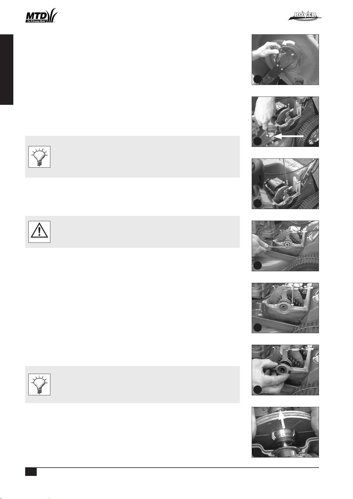
• Unscrew the front and rear phillips head screw in that order (refer figure 14).
• Lift the cover and rotate out of the mower to expose the upper transmission components.
Blow grass and dirt out of the recessed holes to expose the head of the fixings.
Replacing the Drive Frame Cover
• Make sure the raised ring on the brass section of the drive cable nests into the groove of the lower drive support frame and fit the
lid accurately on top before screwing down the cover.
• Do not operate the transmission bale with the cover loose or removed as you will damage the lower drive support frame.
CAUTION
• Fit the drive cable into its retaining slot in the lower drive support frame and hold it down horizontally with one hand
(refer figure 15).
• Rotate the cover into position over the cable until it seats properly and maintain pressure on the lid above the cable.
• Screw the rear fixing above the cable down firmly.
• Screw the forward fixing down firmly.
Leave the fixings in the lid when removing or replacing.
Drive Chain Lubrication
• Refer to the “Warning” and “Caution” notes at the beginning of the maintenance section.
• Do not apply excessive lubricant to the chain as it may flick off and onto the drive clutches during operation.
• Keep lubricant clear of the drive clutches.
WARNING
• Remove the drive frame cover (refer to the “Removing the Drive Frame Cover” section) to expose the drive chain.
• While rotating the outer clutch plate (clockwise) apply an even spread of suitable (non aerosol) chain lubricant along
the length of the chain (refer figure 16).
• Replace the drive frame cover (refer to the “Replacing the Drive Frame Cover” section).
Put the chain lubricant in a container with a long pointed spout to make application easier.
Apply a little of the lubricant on the cams between the clutch engagement lever and the
outboard output shaft bearing retainer while lubricating the chain.
16
15
14
12
13
Anti-clockwise
™
Powered Walk Behind Mower - CE Part No. 04016218 Rev G © Copyright 12/2006
8
ENGLISH
MAINTENANCE (Continued)
Drive Chain Adjustment
• Refer to the “Warning” and “Caution” notes at the beginning of the maintenance section.
• Keep the chain correctly tensioned to prevent damage or abnormal wear.
• Do not over tension the chain.
CAUTION
• Ensure the engine and muffler are cold before attempting to adjust the chain to prevent
burns.
WARNING
• Remove the drive frame cover (refer to the “Removing the Drive Frame Cover” section) and expose the drive chain.
• Using a long slender shaft press firmly on the chain as far from the top sprocket as possible (refer figure 17).
• Using a suitable Phillips head screw driver rotate the adjusting screw until the chain deflection (above) is 5mm (refer
figure 18).
• Rotate the outer clutch plate (chain), recheck chain deflection and re-adjust if necessary.
• Replace the drive frame cover (refer to the “Replacing the Drive Frame Cover” section).
• Rotate the chain adjustment screw clockwise (when looking directly at the head of the
screw) to tighten the chain tension and vice versa.
• Use a very long, or right angle single drive phillips head screw driver to better access the
chain adjusting screw.
• Check the condition of the chain joiner and sprocket and replace if necessary.
Drive Belt Adjustment
• Refer to the “Warning” and “Caution” notes at the beginning of the maintenance section.
• Do not over or under tension the belt to prevent damage or abnormal wear.
CAUTION
• Remove the drive frame cover (refer to the “Removing the Drive Frame Cover” section) and expose the belt adjustment
screw (refer figure 19).
• Using a suitable phillips head screw driver, screw the adjuster screw down carefully until the spring is fully compressed.
• Unscrew the adjuster two (2) full turns.
• Rock the gear box about the output shaft and it should move approximately 2mm under the spring load (refer figure 20).
• Replace the drive frame cover (refer to the “Replacing the Drive Frame Cover” section).
• Clean any clippings away from the underside of the gearbox near the adjusting spring before
adjusting the belt tension.
• Put a mark on one side of the screw head of the adjuster to easily identify the 2 full turns
when adjusting the belt tension.
Drive Belt Replacement
• Refer to the “Warning” and “Caution” notes at the beginning of the maintenance section.
• Refer to the “Caution” notes in the “Belt Adjustment” section.
CAUTION
• Always wear gloves when handling the cutting mechanism.
• Wear gloves and be aware of pinch points when handling the drive belt mechanism.
• Secure the mower safely when tilted upwards to access the underside.
• Place the rear wheels on support blocks so that the rear extension guard will clear the
ground when lifting the front of the mower up. This will prevent damage to the guard which
is a mandatory safety item.
WARNING
• Remove the drive frame cover (refer to the “Removing the Drive Frame Cover” section).
• Unscrew the drive belt adjustment screw until the spring touches the underside of the gearbox housing (refer figure 21).
• Fold the handle bars down and remove the grass catcher and support the rear wheels above the ground on 50mm
(min) blocks.
• Lift the front of the mower about the rear wheels until the lower handle bar contacts the ground and secure safely
in this position.
• Rotate the cutting assembly to expose the two bolts which fix the belt cover (refer figure 22).
• Using a suitable spanner, remove both bolts and washers and remove the belt cover.
• Rotate the gearbox so its pulley is as close to the engine pulley as possible. Rotate the belt off the gearbox pulley
and discard the belt.
19
18
20
17
21
22
™
Powered Walk Behind Mower - CE Part No. 04016218 Rev G © Copyright 12/2006
9
ENGLISH
MAINTENANCE (Continued)
Drive Belt Replacement (Continued)
• Only if the mower is fitted with a full disc and blades will it be necessary to remove the cutting assembly by undoing the
centre bolt and three surrounding bolts with suitable spanners.
• If the mower is fitted with the “Inline Swing Back Blade” option, rotate both blades backward until the flute on the blade
touches the blade support bar (see figure 23).
• Fit the new belt on the engine pulley, rotate the gearbox so its pulley is as close to the engine pulley as possible. Rotate
the belt into the gearbox pulley groove.
• Adjust the drive belt adjustment screw (refer to the “Drive Belt Adjustment” section.)
• Replace the belt cover, flat washers and bolts and tighten firmly.
• Replace the cutting assembly (where required) and fit the centre bolt and washer and the three surrounding bolts and
washers loosely before tightening in the following sequence and tensions - centre bolt (65-70 Nm) and three surrounding
bolts (16-19Nm)
• If the mower is fitted with the “Inline Swing Back Blade” option, rotate the blades back so they are in line with the
blade support bar.
• Lower the mower so all wheels rest on the ground.
• Replace the drive frame cover (refer to the “Replacing the Drive Frame Cover” section).
• Clean the clipping buildup off the heads of the bolts of the belt cover fixings to ensure the
spanner fits correctly.
• Clean out the belt cover and transmission area thoroughly before reassembly.
• Inspect the drive pulleys for wear, damage and make sure they are not loose while the belt
is removed. Replace as required.
• Special belts and pulleys are used for long life and accurate fitment, so replace with genuine
Rover products.
Adjusting the Drive Clutches
Note: This procedure is only necessary should the drive cable adjustment not be able to provide sufficient drive. This
adjustment is to allow for wear on the drive plates in the long term.
• Refer to the “Warning” and “Caution” notes at the beginning of the maintenance section.
CAUTION
• Remove the drive frame cover (refer to the “Removing the Drive Frame Cover” section) to expose the drive clutch
plates and other adjustments.
• Loosen the drive chain fully by unscrewing the chain adjuster (refer figure 24).
• Loosen the drive belt fully by unscrewing the drive belt adjuster (refer figure 25).
• Using a suitable Allen key, remove the centre fixing and thrust washer from the end of the output shaft (refer figure 26).
• Remove the two fixings retaining the outboard output shaft bearing housing (refer figure 27).
• Lift the outer end of the output shaft slightly and slide off the outboard output shaft bearing retainer (refer figure 28).
• Take note of which marking (on the boss of the inner drive plate) aligns with the end of the locking roll pin (through
the output shaft) (refer figure 29).
• Move the drive plates and actuating cam in an outboard direction until the inner drive plate is free of the roll pin
(refer figure 29).
• Rotate the inner driver plate until the roll pin aligns with the marking with ONE extra groove than that originally noted
above. Slide back to lock the drive plate to the roll pin into its new position.
• Replace the outer output shaft bearing retainer and screw down firmly in position.
• Replace the centre fixing and thrust washer on the end of the output shaft, apply thread locking solution to the centre
fixing and tighten firmly.
• Readjust the drive chain (refer to the “Drive Chain Adjustment” section).
• Readjust the drive belt (refer to the “Drive Belt Adjustment” section).
• Replace the drive frame cover (refer to the “Replacing Drive Frame Cover” section).
• Re-adjust the clutch cable (refer to the “Adjusting the Drive Cable” section).
• The marks on the inner drive plate boss represents positions ‘1’, ‘11’, & ‘111’. Setting ‘1’ is
generally used with a new drive plate whereas position ‘111’ is for a worn unit.
• If the drive cable adjustment is insuff icient with the inner drive plate in position ‘111’ the
drive plates must be replaced.
• Clean off and apply new grease to the cams of the outboard output shaft bearing retainer
and cam lever before reassembly.
25
26
24
27
28
29
23
™
Powered Walk Behind Mower - CE Part No. 04016218 Rev G © Copyright 12/2006
10
ENGLISH
MAINTENANCE (Continued)
Lubricating the Drive Pawls
• Support the rear wheels off the ground.
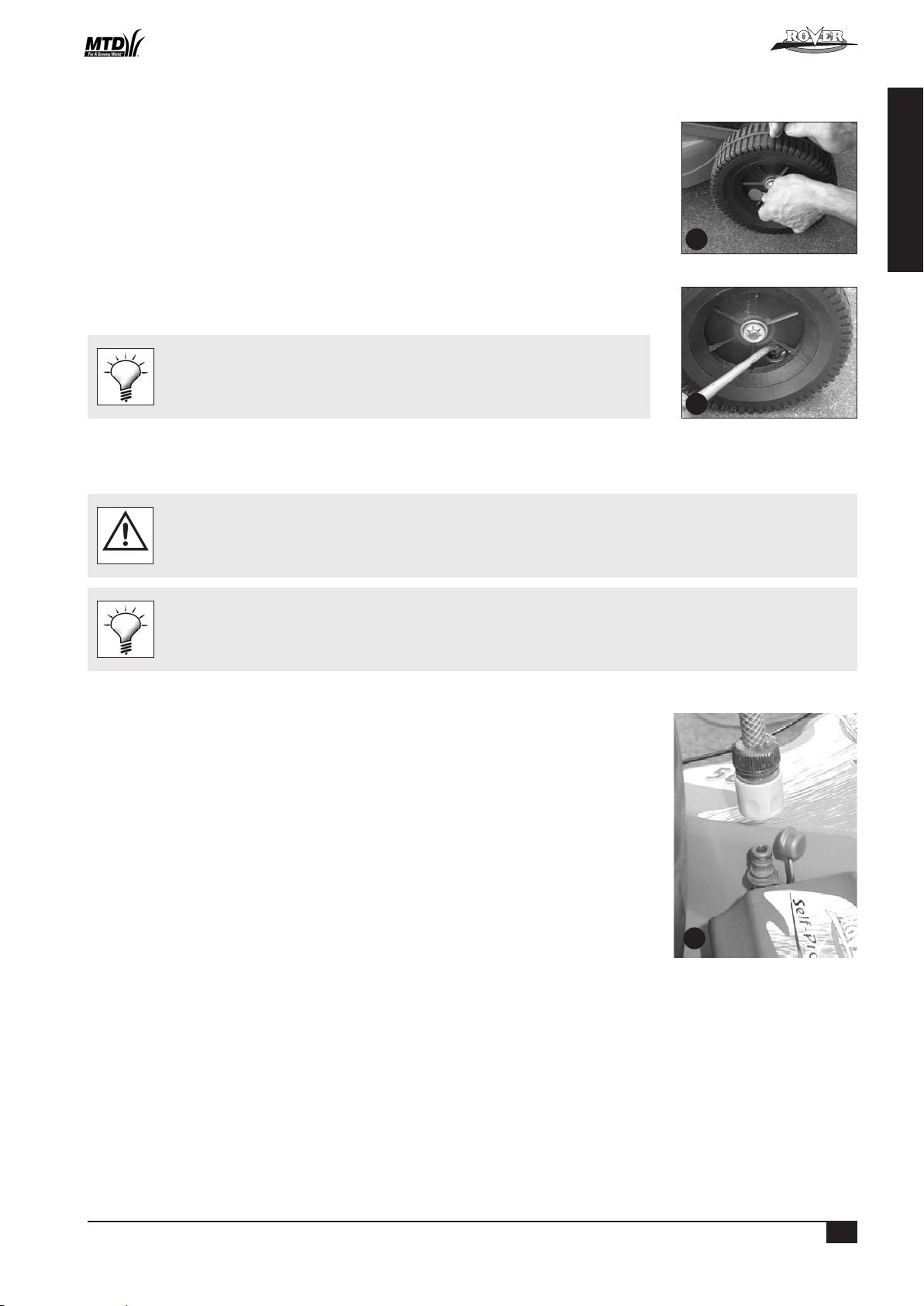
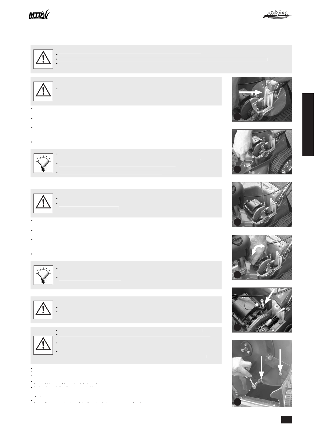
• Remove the rear hubcaps and wheel plugs (refer figure 30).
• Inspect the inside of the wheel hub through the wheel plug hole. If dirt is found, the wheel should be removed and
cleaned.
• To remove the wheel, remove the ratchet plate securing the wheel to the axle.
• Withdraw the wheel from the axle and clean out thoroughly.
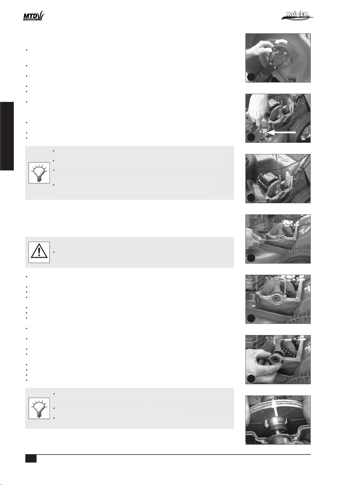
• Using clean engine oil, apply a few drops of oil to the end of the drive gear above the retaining washer and
rotate the gear to allow the oil to penetrate (refer figure 31). The gear should rotate freely, if not, repeat the
above procedure.
• Replace the wheel, washer and secure with a new ratchet plate.
• If the wheel hub is clean, rotate the wheel until the drive gear is visible through the wheel plug hole.
• Using clean engine oil, apply a few drops of oil to the end of the drive gear (as above) and rotate the wheel one or two
times to allow the oil to penetrate. The wheel should rotate freely, if not repeat the procedure (refer figure 31).
• Replace the wheel plugs and the hubcaps.
• Use a thin bladed screwdriver or similar between the hubcap and the wheel to prise off the
hubcap, being careful not to over bend it.
• Ratchet plates require special tools to remove and replace them. If you are unsure, contact
your nearest authorized Rover dealer.
• Purchase new ratchet plates before removing the wheels as they are not reusable.
POWERSTART OPTION
N.B. The battery maintenance details are covered in the setting up section and the following matrix.
• Refer to the “Warning” and “Caution” notes at the beginning of this section.
CAUTION
Keep battery fully charged to ensure maximum service life.
30
31
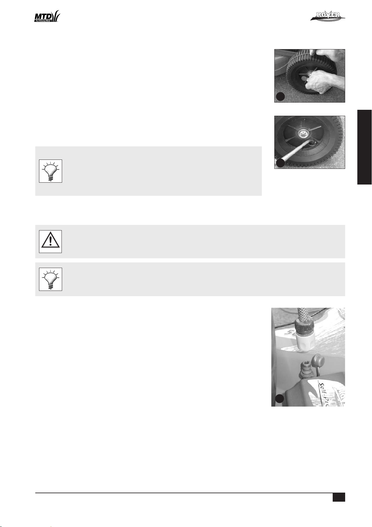
Mower cleaning using optional washport
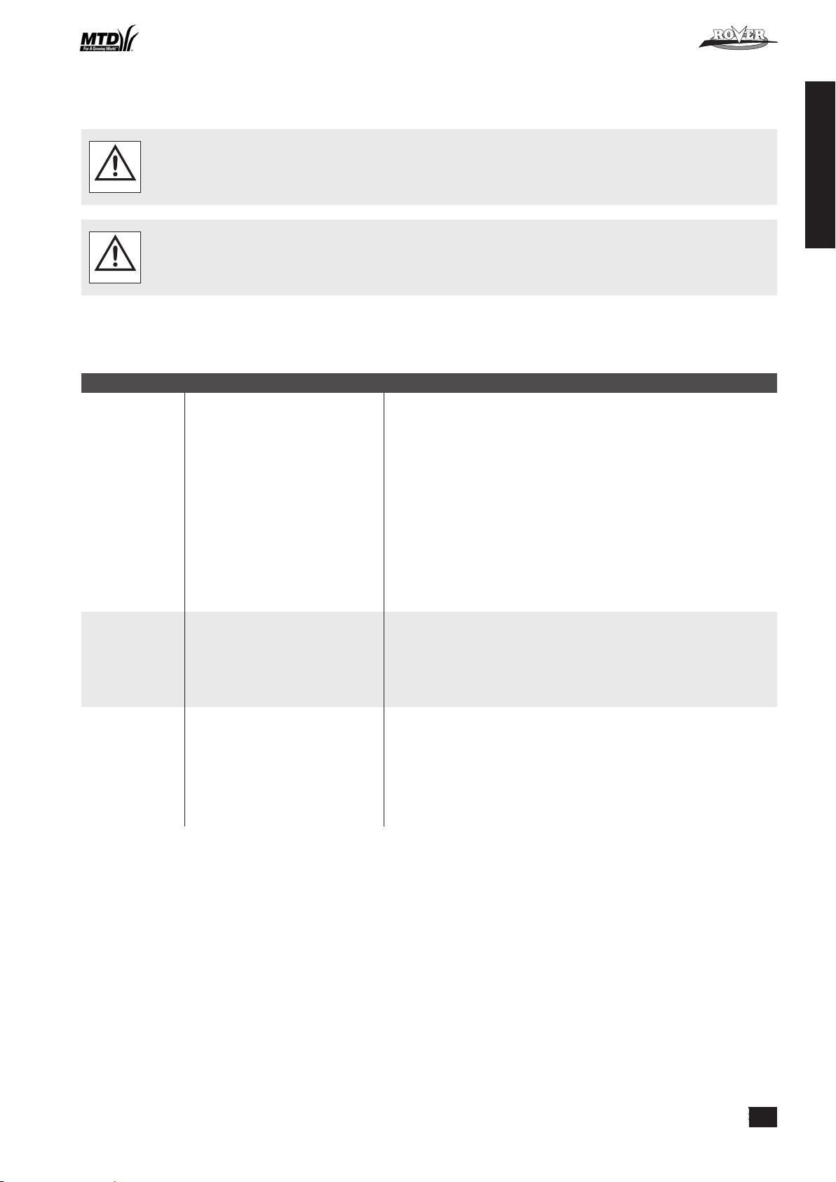
• Place the mower outdoors on a flat surface.
• Set the cut height to high cut position.
• With the engine stopped connect a garden hose with a snap on connection ( remove the cap first), to
the washport fitted to the inside face of the cutting chamber. (refer figure 32.)
• Turn the garden hose on.
• Return to the mower and start the engine and run at full speed for 1 minute.
• Stop the engine and turn off the garden hose.
• Remove the garden hose from the washport and replace the cap.
• Inspect the underside of the mower, if not completely clean use the garden hose to flush out
the remaining debris.
32
™
Powered Walk Behind Mower - CE Part No. 04016218 Rev G © Copyright 12/2006

11
ENGLISH
Throttle cable Inspect and lubricate
•
Oil inner cable if tight. Replace if kinked or
damaged.
Operator presence Check the blade brake stops the
•
Have the engine serviced by an authorised
control engine when the lever is released service agent if in doubt or not functioning.
Lubricate the lever pivots
•
Wiring loom Inspect
•
Replace if damaged.
(where fitted)
Before After While Every Every
Components Action Mowing Mowing Mowing 5 hours 25 hours Special Considerations
Overall mower Clean the upper and underside
•
Engine air cleaner Visually inspect and clean
•
Refer to the engine manufacturer’s manual for
elements instructions.
Engine oil Check level
•
Refer to the engine manufacturer’s manual for
instructions.
Engine oil Replace
Refer to the engine manufacturer’s manual for
instructions.
Engine spark plug Inspect and clean
Refer to the engine manufacturer’s manual for
instructions.
Engine general Inspect and clean
•
Refer to the engine manufacturer’s manual for
instructions.
Cutting blades Inspect
•
Replace if worn, bent, damaged or if the assembly
is out of balance.
Drive cable Inspect for damage or kinks
•
Replace if necessary.
(where fitted)
Adjustment
•
•
Drive assembly Inspect and clean •
under drive frame
cover (where fitted)
Drive chain Lubrication
Every 50 hours.
(where fitted)
Adjustment Every 100 hours.
Drive belt Inspect and clean
•
(where fitted) Adjustment • Replace belt if adjustment procedure does not
restore full drive
Drive Belt Cover Remove, clean and inspect
Every 50 hours.
Drive Pawls Inspect, clean, lubricate
•
In boggy conditions inspect more regularly and
(where fitted) clean and lubricate as required.
Guards and safety Inspect and clean
•
Replace before next mowing.
labels
Battery Inspect and clean
•
Make sure the battery is firmly supported in the
(where fitted) support box.
Recharging
As required but mainly after long periods of non use.
Key switch Inspect
•
Replace if damaged.
(where fitted)
MAINTENANCE (Continued)
™
Powered Walk Behind Mower - CE Part No. 04016218 Rev G © Copyright 12/2006
12
ENGLISH
TROUBLESHOOTING
GENERAL
• Never attempt any corrective action that is not outlined in this or associated manuals. Refer to your nearest authorised Rover dealer.
• Always replace components with genuine Rover replacement parts.
WARNING
• Use the associated engine manufacturers manual for engine related trouble shooting and corrective action instructions.
CAUTION
• Refer to the relevant sections in this manual for corrective action instruction.
• Other manuals maybe included with your mower, which may relate to specific options of the mower. Use these manuals for specific trouble shooting related
to the options.
Problem Possible Causes Corrective Action
Uneven Grass Cutting • Blades are blunt/worn/bent
• Engine speed is too slow
• Cut height is too low
• Ground speed is too fast
• Replace blades
• Use full engine speed
• Raise cut height
• Slow down the ground speed
Engine won’t start • Fuel supply
• Air cleaner
• Spark Plug
• Operator presence control
• Fill the fuel tank*
• Prime the fuel system*
• Turn the fuel tap on (where fitted)*
• Drain and replace, stale or contaminated fuel*
• Move throttle or choke or fast position
• Re-adjust throttle control cable*
• Have the engine serviced by an authorised service agent
• Clean or replace air filter*
• Clean/adjust/replace spark plug*
• Refit the spark plug wire
• Have the engine serviced by an authorised service agent
• Activate operator presence control
• Reconnect/replace disconnected/broken cable
• Have the engine brake serviced by an authorised service agent
Clippings drop while
grass catching
• Refer to “Uneven Grass Cutting” section
items
• Grass catcher is full
• Grass catcher mesh/vents are dirty/
blocked
• Grass catcher is damaged
• Refer to “Uneven Grass Cutting” section items
• Empty the grass catcher
• Clean the mesh/vents to allow maximum air flow
• Replace the grass catcher
*Denotes: Refer to the engine manufacturer’s manual for details and instructions.
™
Powered Walk Behind Mower - CE Part No. 04016218 Rev G © Copyright 12/2006

13
ENGLISH
POWERSTART OPTION
Problem Possible Causes Corrective Action
Engine won’t crank • Refer to “Engine Cranks Slowly” section
items
• Faulty key switch
• Faulty starter motor on the engine
• Operator presence control
• Refer to “Engine Cranks Slowly” section items
• Replace the key switch
• Have the engine serviced at an authorised service dealer
• Activate operator presence control
• Reconnect/replace disconnected/broken cable
• Have the engine brake serviced by an authorised service agent
Engine cranks slowly • Bad electrical connections
• Faulty/flat battery
• Reconnect connections securely
• Replace faulty electrical cables
• Replace/recharge the battery
SELF PROPELLED OPTION
Problem Possible Causes Corrective Action
Transmission doesn’t
drive
• Refer to “Transmission Slips Under Load”
section items
• Gearbox is damaged or seized
• Clutch Plate drive pin is broken
• Final drive sprocket roll pin is broken
• Broken/dislodged drive chain
• Broken/dislodged drive belt
• Engine drive pulley key broken
• Gear box pulley roll pin broken
• Pinion gears/pawls in the drive wheels
broken/worn
• Refer to “Transmission Slips Under Load” section items
• Replace gearbox
• Replace roll pin
• Replace roll pin
• Replace/refit drive chain
• Replace/refit drive belt
• Replace key in drive pulley
• Replace roll pin
• Replace broken/worn components
Transmission slips
under load
• Drive cable damaged/disconnected/not
adjusted correctly
• No adjustment left in the drive cable
• Drive clutches damaged or worn
• Slipping drive belt
• Replace/reconnect/adjust drive cables
• Adjust drive clutches
• Replace drive cable
• Replace drive plates
• Readjust or replace the drive belts
• Replace worn drive pulley
• Replace broken belt tensioning spring
Mower doesn’t free
wheel easily when
drive is in neutral
• Rear wheels jammed with foreign material
• Pawls in the rear wheels are damaged or
seized
• Bearings in wheels are seized.
• Clean out and re-lubricate rear wheels
• Replace or re-lubricate the pawls
• Replace wheels bearings
™
Powered Walk Behind Mower - CE Part No. 04016218 Rev G © Copyright 12/2006
™
14
DEUTSCH
VORWORT
ACHTUNG
ACHTUNG
VORSICHT
TECHNISCHE DATEN
Auf/Zusammenklappen des Griffs
Abnehmen der Verpackungsbänder von den Steuergriffen
Ausführung Powerstart
Ausführung mit Eigenantrieb
- Anbau des Grasfangkorbs
- Abbau des Grasfangkorbs
- Motor anlassen
- Motor stoppen
Ausführung mit Eigenantrieb
- Bedienung des Getriebes
Allgemeine Reinigung
- Reinigung der Mäherunterseite
- Reinigung der Mäheroberseite
Auswechseln der Messer
Ausführung mit Eigenantrieb
- Einstellung des Kupplungszugs
- Abnehmen der Antriebsabdeckung
- Aufsetzen der Antriebsabdeckung
- Schmierung der Antriebskette
- Einstellung der Antriebskette
- Einstellung des Antriebsriemens
- Austausch des Antriebsriemens
- Einstellung der Antriebskupplungen
- Schmierung der Antriebsklinken
Ausführung Powerstart
Allgemeines
Ausführung Powerstart
Ausführung mit Eigenantrieb
ANSICHT ERSATZTEILE
Powered Walk Behind Mower - CE Part No. 04016218 Rev G © Copyright 12/2006
15
DEUTSCH
ANLEITUNG
VORBEREITUNG
ACHTUNG - Benzin ist hochentzündlich. Treffen Sie die erforderlichen Sicherheitsvorkehrungen:
Verschüttungsbereich und vermeiden Sie es, irgendwelche Zündquellen zu erzeugen, bevor sich die Treibstoffdämpfe
verflüchtigt haben
Aus Sicherheitsgründen müssen bei Beschädigung Tank und Tankdeckelschloss ersetzt werden.
Vergewissern Sie sich vor der Inbetriebnahme, dass die Messer, Messerschrauben und Schneiden nicht abgetragen oder
vermeiden.
Wenn möglich nicht in nassem Gras mähen.
Achten Sie bei der Arbeit auf Hängen immer auf einen sicheren Stand.
Auf keinen fall laufen - gehen Sie in normalem Tempo
Auf keinen Fall den Drehzahlbegrenzer verstellen oder den Motor überdrehen.
Vor dem Anlasen des Motors alle Messer und Antriebskupplungen lösen bzw. auskuppeln.
Auf keinen Fall Hände oder Füße unter drehende Teile bringen. Nie vor den Auslassöffnungen stehen.
Vor dem Nachtanken.
Abschluss der Mäharbeiten schließen.
WARTUNG UND AUFBEWAHRUNG
Alle Muttern und Schrauben immer fest angezogen halten, so dass das Gerät immer ordnungsgemäß und sicher arbeitet.
Zur Reduzierung der Brandgefahr Motor, Schalldämpfer, Batteriefach und Benzinlagerbereich frei von Gras, Blättern und
Verschlissene oder defekte Bauteile aus Sicherheitsgründen erneuern.
ACHTUNG
™
Powered Walk Behind Mower - CE Part No. 04016218 Rev G © Copyright 12/2006
™
16
DEUTSCH
- Modelle 51, 61
- Schnittbreite 508 mm
- 12 einstellbare Schneidhöhen
- Modelle 80
- Schnittbreite 560 mm
- 15 einstellbare Schneidhöhen
- Alle Modelle sind mit einem Motor aus einer breiten Palette an Motoren ausgerüstet (siehe das Motorhandbuch im
- Die folgenden Optionen sind für die oben genannten Modelle erhältlich (und u.U. schon enthalten), z.B.:
- Mulchmähen
- Mähen mit Abweiser
- Externer Luftfilter
- Ausführung Powerstart
- Ausführung mit Eigenantrieb
- usw.
- Weitere Details können in diesem oder einem anderen Handbuch in diesem Satz gefunden werden.
VORBEREITUNGEN
ZUSAMMENBAU DES GRASFANGKORBS
Stecken Sie die Schrauben von außen in die Behälter; die Unterlegscheiben und Nyloc-Muttern gehören auf die
Innenseite des Behälters.
AUF/ZUSAMMENKLAPPEN DES GRIFFS
zusammengeklappt werden.
Vergewissern Sie sich, dass sich der Drosselregler in der Stellung “Stopp” befindet (siehe
1
2
4
A
3
Powered Walk Behind Mower - CE Part No. 04016218 Rev G © Copyright 12/2006
17
DEUTSCH
VORBEREITUNGEN
ABNEHMEN DER VERPACKUNGSBÄNDER VON DEN STEUERGRIFFEN
Vor der Inbetriebnahme des Mähers unbedingt die Verpackungsbänder abnehmen, mit denen
Abbildung 5)
ACHTUNG
VORSICHT
AUSFÜHRUNG POWERSTART
Verschüttete Elektrolytflüssigkeit muss mit einer Lauge neutralisiert werden.
ACHTUNG
AUSFÜHRUNG MIT EIGENANTRIEB
Vor der Inbetriebnahme des Mähers unbedingt die Verpackungsbänder abnehmen, mit denen der Steuergriff für den Eigenantrieb an
ACHTUNG
vorgeschriebene Sicherheitsvorrichtung, mit der eine Bremse am Motor betätigt wird. Wird der Hebel an die Lenkstange gedrückt,
wird die Bremse gelöst und die Messer sowie der Motor können frei laufen. Sobald der Hebel losgelassen wird, wird die Bremse
ACHTUNG
ACHTUNG
6
5
™
Powered Walk Behind Mower - CE Part No. 04016218 Rev G © Copyright 12/2006
™
18
DEUTSCH
Anbau des Grasfangkorbs
Abbau des Grasfangkorbs
ACHTUNG
verfahren.
VORSICHT
ACHTUNG
Totmannschalter zu aktivieren.
Auf der Rover-Drosselsteuerung wird die Drosselfunktion bei den verschiedenen Stellungen mit entsprechenden Symbolen dargestellt:
(
), (),
(Cho
(Aus),
(start).
7
8
Powered Walk Behind Mower - CE Part No. 04016218 Rev G © Copyright 12/2006
19
DEUTSCH
ACHTUNG
AUSFÜHRUNG MIT EIGENANTRIEB
werden.
WARTUNG
Auf keinen Fall Geräte mit verschlissenen oder defekten Komponenten verwenden.
Verwenden Sie immer Original-Rover-Ersatzteile.
Zur Vermeidung von Brandgefahr müssen jegliche Mährückstände aus dem Bereich des Schalldämpfers entfernt werden.
ACHTUNG
VORSICHT
9
™
Powered Walk Behind Mower - CE Part No. 04016218 Rev G © Copyright 12/2006
™
20
DEUTSCH
WARTUNG
ALLGEMEINE REINIGUNG
Auf keinen Fall bei laufendem Motor die Auswurfklappe öffnen oder den Mäher zum waschen des Unterbodens anheben.
ACHTUNG
AUSWECHSELN DER MESSER
ACHTUNG
Vor dem Ansetzen des Schraubenschlüssels jegliche Grasreste entfernen.
Verwenden Sie einen Ring- oder Steckschlüssel, um ein Abrutschen oder Beschädigen der
AUSFÜHRUNG MIT EIGENANTRIEB
ACHTUNG
ACHTUNG
VORSICHT
10
11
Powered Walk Behind Mower - CE Part No. 04016218 Rev G © Copyright 12/2006
™
21
DEUTSCH
WARTUNG
Abbildung 12).
Testen Sie bei allen Drehzahleinstellungen, ob das Gerät von selbst auskuppelt, wenn der Kupplungshebel losgelassen wird,
Vergewissern Sie sich, dass der Zug keine Beschädigungen oder Knicke aufweist und so den
Abnehmen der Antriebsabdeckung
Aufsetzen der Antriebsabdeckung
Vergewissern Sie sich, dass sich der erhabene Ring auf dem Messingteil des Zugs in die Nut auf dem unteren Antriebslagerrahmen
Antriebslagerrahmen beschädigt wird.
VORSICHT
Auf keinen Fall zuviel Schmiermittel auf die Kette auftragen, da diese sonst während des Betriebs auf die Antriebskupplungen
ACHTUNG
16
15
14
12
13
Anti-clockwise
Powered Walk Behind Mower - CE Part No. 04016218 Rev G © Copyright 12/2006
™
22
DEUTSCH
WARTUNG
VORSICHT
Vergewissern Sie sich, dass Motor und Schalldämpfer abgekühlt sind, bevor Sie die Kette
justieren, um Verbrennungen zu vermeiden.
ACHTUNG
wird die Kettenspannung erhöht; das Verringern der Spannung erfolgt umgekehrt
VORSICHT
zusammengedrückt ist.
Vor dem Einstellen der Riemenspannung sollten jegliche Grasrückstände von der
wann 2 Umdrehungen erreicht sind.
Austausch des Antriebsriemens
VORSICHT
werden Beschädigungen an der gesetzlich vorgeschriebenen Schutzblende vermieden.
ACHTUNG
Abbildung 22).
Abbildung 22).
Abbildung 22).
19
18
20
17
21
22
Powered Walk Behind Mower - CE Part No. 04016218 Rev G © Copyright 12/2006
23
DEUTSCH
WARTUNG
Austausch des Antriebsriemens (Fortsetzung)
werden, bis die Kehlnute des Messers die Messertragstange berührt (siehe Abbildung 23).
Justieren Sie die Riemeneinstellschraube (siehe Abschnitt “Einstellung des Antriebsriemens”)
von allen Grasrückständen gereinigt werden.
Vor dem Einbau sollten die Riemenabdeckung und der Getriebebereich gründlich gereinigt
werden.
VORSICHT
Antriebskupplungsplatten und andere Einstellungen freizulegen.
Justieren Sie die Antriebskette (siehe Abschnitt “Einstellung der Antriebskette”).
Justieren Sie den Antriebsriemen (siehe Abschnitt “Einstellung des Antriebsriemens”).
Justieren Sie den Kupplungszug (siehe Abschnitt “Einstellung des Kupplungszugs”).
justiert werden, müssen die Antriebsplatten ausgetauscht werden.
25
26
24
27
28
29
23
™
Powered Walk Behind Mower - CE Part No. 04016218 Rev G © Copyright 12/2006
24
DEUTSCH
WARTUNG
Schmierung der Antriebsklinken
• Die Hinterräder anheben und in ausreichendem Abstand vom Boden abstützen.
• Die Nabenkappen und Radstopfen der Hinterräder abnehmen (siehe Abbildung 30).
•Das Innere der Radnabe durch die Radstopfenbohrung hindurch sichtprüfen. Evtl. vorhandener Schmutz muss entfernt
werden.
• Zum Ausbau des Rades wird die Rasterplatte, welche des Rad an der Achse fixiert, abgenommen.
• Ziehen Sie das Rad von der Achse ab und reinigen Sie es sorgfältig.
• Einige Tropfen sauberen Motoröls auf das Ende des Antriebszahnrads über der Haltescheibe aufbringen. Drehen Sie
nun das Zahnrad, so dass das Öl eindringen kann (siehe Abbildung 31). Das Rad muss sich nun frei drehen können,
falls nicht, muss der Vorgang wiederholt werden.
• Rad und Haltescheibe wieder aufsetzen und mit einer neuen Rasterplatte befestigen.
•Ist die Radnabe sauber, drehen Sie das Rad, bis Sie durch die Radstopfenbohrung hindurch das Antriebszahnrad sehen
können.
• Einige Tropfen sauberen Motoröls auf das Ende des Antriebszahnrads über der Haltescheibe aufbringen (wie oben).
Drehen Sie nun das Rad ein oder zwei Mal, so dass das Öl eindringen kann. Das Rad muss sich nun frei drehen können,
falls nicht, muss der Vorgang wiederholt werden (siehe Abbildung 31).
• Die Radstopfen und die Nabenkappen wieder anbringen.
• Die Nabenkappen können mit einem feinen Schraubendreher oder einem ähnlichen
Werkzeug abgenommen werden, indem die Klinge des Schraubendrehers zwischen
Nabenkappe und Rad gesetzt und die Kappe abgehebelt wird. Achten Sie dabei darauf, die
Kappe nicht zu verbiegen.
• Die Rasterplatten müssen mit besonderem Werkzeug ausgewechselt werden. Sollten Sie
sich nicht sicher sein, wenden Sie sich an Ihren nächstgelegenen Rover-Fachhändler.
• Besorgen Sie sich neue Rasterplatten, bevor Sie die Räder abbauen, da diese Platten nicht
wiederverwendet werden können.
AUSFÜHRUNG POWERSTART
P.S. Die Details zur Batteriewartung werden unter “Vorbereitungen” und in der folgenden Matrize behandelt.
• Siehe die Hinweise “Achtung” und “Vorsicht” am Anfang dieses Abschnitts.
VORSICHT
Die Batterie sollte immer vollständig geladen sein, um maximale Lebensdauer zu gewährleisten.
30
31
Reinigung des Mähers mit Waschanschluss (Zubehör):
Stellen Sie den Mäher im Freien auf eine ebene Fläche.
Stellen Sie die Schnitthöhe auf die HOHE Position ein.
Schließen Sie wie in Abb. 32 gezeigt bei ausgeschaltetem Motor einen Gartenschlauch mit Steckverbindung an
den Waschanschluss im Inneren des Messergehäuses an (erst Kappe abnehmen).
Drehen Sie den Gartenschlauch auf.
Starten Sie den Motor des Mähers und betreiben Sie ihn eine Minute lang bei VOLLER Geschwindigkeit.
Stoppen Sie den Motor und drehen Sie den Gartenschlauch ab.
Nehmen Sie den Gartenschlauch vom Waschanschluss ab und bringen Sie die Kappe wieder an.
Prüfen Sie die Unterseite des Mähers. Ist sie noch nicht völlig gereinigt, spülen Sie etwaige Gras- und
Schmutzreste mit dem Gartenschlauch ab.
32
™
Powered Walk Behind Mower - CE Part No. 04016218 Rev G © Copyright 12/2006
25
DEUTSCH
WARTUNG
Totmannschalter
Vor dem Nach dem Während Alle Alle
Komponenten Maßnahme Mähen Mähen
Mähen 5 Stunden 25 Stunden Weiterhin
Auf Beschädigungen und Knicke
Antrieb unter
Antriebsabdeckung
Antriebskette
Alle 50 Stunden.
Alle 100 Stunden.
Antriebsriemen
Ausbauen, reinigen und prüfen
Alle 50 Stunden.
Antriebsklinken
Aufnahmebehälter sitzt.
Aufladen
™
Powered Walk Behind Mower - CE Part No. 04016218 Rev G © Copyright 12/2006

26
DEUTSCH
ALLGEMEINES
Verwenden Sie immer Original-Rover-Ersatzteile.
ACHTUNG
Anleitungen zum jeweiligen Problem finden.
VORSICHT
Anleitungen zur Problembehebung bei diesen Ausstattungsvarianten.
Problem Mögliche Ursache Behebung des Problems
verschmutzt/verstopft
™
Powered Walk Behind Mower - CE Part No. 04016218 Rev G © Copyright 12/2006

27
DEUTSCH
AUSFÜHRUNG POWERSTART
Problem Mögliche Ursache Behebung des Problems
Anlassen nur langsam
AUSFÜHRUNG MIT EIGENANTRIEB
Problem Mögliche Ursache Behebung des Problems
Antrieb
Antriebskette gerissen/abgesprungen
Antriebsriemen gerissen/abgesprungen
verschlissen
werden
Antriebskupplungen verschlissen oder
Antriebsriemen rutscht
™
Powered Walk Behind Mower - CE Part No. 04016218 Rev G © Copyright 12/2006

™
28
FRANÇAIS
Veuillez lire et assimiler le contenu de ce manuel et d’autres manuels qui peuvent y être joints avant d’utiliser cette machine. En cas
- Installation du bac de ramassage
- Pour enlever le bac de ramassage
- Démarrage du moteur
- Arrêt du moteur
- Utilisation de la transmission autotractée
- Nettoyage du dessous de la tondeuse
- Nettoyage du carter de la tondeuse
- Réglage du câble d’entraînement
- Pour enlever le carter du châssis d’entraînement
- Pour replacer le carter du châssis d’entraînement
- Lubrification de la chaîne d’entraînement
- Réglage de la chaîne d’entraînement
- Réglage de la courroie d’entraînement
- Pour remplacer la courroie d’entraînement
- Réglage des embrayages d’entraînement
- Lubrification des cliquets d’entraînement
Powered Walk Behind Mower - CE Part No. 04016218 Rev G © Copyright 12/2006

™
29
FRANÇAIS
Ajoutez du carburant avant de faire démarrer le moteur. Veillez à ne pas enlever le bouchon du réservoir ou ajouter
Veillez à ne pas perdre l’équilibre sur les pentes.
Veillez à ne pas changer les réglages de commande du moteur ou à ne pas emballer le moteur.
Arrêtez le moteur et débranchez le fil de la bougie:
Arrêtez le moteur:
Assurez-vous que tous les écrous, boulons et vis sont bien serrés pour que l’équipement soit en bonne condition de marche.
Vérifiez souvent le bac de ramassage pour vous assurer qu’il n’est ni usé ni détérioré.
Powered Walk Behind Mower - CE Part No. 04016218 Rev G © Copyright 12/2006

™
30
FRANÇAIS
- Modèles 51, 61
- Largeur de coupe: 20” (508 mm)
- 12 réglages de hauteur de coupe
- Modèle 80
- Largeur de coupe: 22” (560 mm)
- 15 réglages de hauteur de coupe.
- Exemples d’options disponibles (et inclues, dans certains cas) sur les modèles précédemment décrits.
- Tonte de paillis
- Tonte avec déflecteur
- Filtre à air à télécommande
- Fonction de démarrage électrique
- Fonction autotractée
- Etc.
- Détails inclus dans ce manuel ou dans un manuel fourni séparément dans le kit de la tondeuse.
Appuyez fort sur le haut du bac pour faire entrer les barbes dans les fentes (voir figure 2).
Joindre ensemble, sur le devant, les deux moitiés supérieure et inférieure du dispositif pour recueillir l’herbe coupée, en
Avant de déplier le guidon, assurez-vous que la commande d’accélération est à l’arrêt (voir
AF (voir figure 4).
Assurez-vous que les éléments suivants se trouvent dans l’emballage (voir la figure 1):
Tondeuse
Au cas où des articles manqueraient, veuillez en informer au plus vite le magasin où vous l’avez acheté.
1
2
4
A
3
Powered Walk Behind Mower - CE Part No. 04016218 Rev G © Copyright 12/2006

™
31
FRANÇAIS
Avant d’essayer de faire démarrer la tondeuse, enlevez et mettez au rebut les
Veillez à ne laisser entrer aucune poussière ou impureté dans le réservoir ou le tube du filtre à huile.
Veillez à ne pas démonter, faire tomber ou endommager la batterie.
Avant d’essayer de faire démarrer la tondeuse, enlevez et mettez au rebut les fixations d’emballage (voir figure 5).
Veillez à ne jamais installer ou enlever le bac de ramassage pendant que le moteur est en marche.
6
5
Powered Walk Behind Mower - CE Part No. 04016218 Rev G © Copyright 12/2006

™
32
FRANÇAIS
Mulch’n’Catch
(Paillis).
(
), (), (), ()
(
), ().
Arrêt du moteur
7
8
Powered Walk Behind Mower - CE Part No. 04016218 Rev G © Copyright 12/2006

™
33
FRANÇAIS
Veuillez consulter les instructions consignées dans les directives de sécurité de ce manuel et des autres manuels qui y sont joints, et
vous conformer à ces instructions.
Arrêtez le moteur, enlevez et videz le bac.
vitesse augmente à mesure que vous rapprochez la commande du guidon (voir figure 9).
Tenez la commande à la vitesse désirée et ralentissez ou accélérez selon les circonstances.
Assurez-vous toujours que le matériel est en bon état de marche.
Assurez-vous toujours que le moteur soit arrêté et enlevez le fil de la bougie avant de travailler sur la tondeuse.
Veuillez consulter le manuel du constructeur et vous y conformer.
Veillez à ce que la tondeuse soit sèche et propre avant de la ranger dans un espace bien aéré.
9
Powered Walk Behind Mower - CE Part No. 04016218 Rev G © Copyright 12/2006

™
34
FRANÇAIS
Après avoir arrêté le moteur, enlever le bac de ramassage et ouvrir le volet d’évacuation en le soulevant.
Après avoir arrêté le moteur et enlevé le fil de la bougie et le bac de ramassage, ouvrez le volet d’évacuation et
Après vous être muni de gants, enlevez le bloc de coupe à l’aide d’une clé appropriée.
10
11
Powered Walk Behind Mower - CE Part No. 04016218 Rev G © Copyright 12/2006

™
35
FRANÇAIS
Tester la tondeuse à toutes les vitesses pour vous assurer qu’elle débraye automatiquement quand la commande de
Assurez-vous que le câble n’est pas détérioré ou tordu, ce qui peut affecter la marche de la
Assurez-vous que la bague surélevée placée sur la section de cuivre du câble d’entraînement se loge dans la rainure du dessous du
Tout en faisant pivoter le disque externe d’embrayage (dans le sens des aiguilles d’une montre), appliquez une couche
16
15
14
12
13
Anti-clockwise
Powered Walk Behind Mower - CE Part No. 04016218 Rev G © Copyright 12/2006

™
36
FRANÇAIS
Assurez-vous de la bonne tension de la chaîne pour éviter de l’abîmer ou de l’user prématurément.
A l’aide d’une longue tige mince, appuyez fermement sur la chaîne aussi loin que possible du
Vérifiez l’état du joint de chaîne et du pignon d’entraînement, et remplacez-les si nécessaire
Assurez-vous de la bonne tension de la courroie - ni trop ni insuff isamment tendue - pour
A l’aide d’un tournevis cruciforme, vissez délicatement la vis de réglage jusqu’à compression totale du ressort.
Veillez à toujours porter des gants pour manipuler le dispositif de coupe.
Assurez-vous de l’équilibre de la tondeuse quand vous l’inclinez vers le haut pour atteindre
A l’aide d’une clé appropriée, enlevez les deux boulons et leurs rondelles et enlevez le carter de la courroie.
19
18
20
17
21
22
Powered Walk Behind Mower - CE Part No. 04016218 Rev G © Copyright 12/2006

™
37
FRANÇAIS
Pour remplacer la courroie d’entraînement (suite)
Ajuster la vis de réglage de la courroie d’entraînement (consulter la section “Réglage de la courroie d’entraînement”).
Abaisser la tondeuse pour que toutes les roues reposent sur le sol.
Vérifiez que les poulies d’entraînement ne sont pas usées ou détériorées et assurez-vous
A l’aide d’une clé Allen appropriée, enlever la fixation centrale et le disque de butée de l’extrémité de l’arbre de sortie
verrouillage (à travers l’arbre de sortie) (voir figure 29).
25
26
24
27
28
29
23
Powered Walk Behind Mower - CE Part No. 04016218 Rev G © Copyright 12/2006

38
FRANÇAIS
ENTRETIEN (suite)
Lubrification des cliquets d’entraînement
• Soulever les roues arrières au-dessus du sol.
• Enlever les enjoliveurs et les chevilles des roues arrières (voir figure 30).
•Examiner l’intérieur du moyeu de la roue à travers le trou de la cheville. S’il y a des impuretés,
enlever la roue et la nettoyer.
• pour enlever la roue, enlever la plaque à cliquet qui fixe la roue à l’essieu.
• sortir la roue de l’essieu et nettoyez à fond.
• Appliquer quelques gouttes d’huile pour moteur - utiliser de l’huile propre - à l’extrémité de la boîte à
engrenage au-dessus de la rondelle de retenue et faire tourner l’engrenage pour que l’huile pénètre (voir
figure 31). L’engrenage devrait tourner librement, sinon, répétez l’opération décrite ci-dessus.
•Replacer la roue et la rondelle, et la fixer avec une nouvelle plaque à cliquet.
• Si le moyeu est propre, faire tourner la roue jusqu’à ce que la boîte à engrenage soit visible à travers le trou
de la cheville de la roue.
• Appliquer quelques gouttes d’huile pour moteur - utiliser de l’huile propre - à l’extrémité de la boîte à engrenage (comme
ci-dessus) et faire tourner l’engrenage pour que l’huile pénètre. L’engrenage devrait tourner librement, sinon, répéter
l’opération décrite ci-dessus (voir figure 31).
• Replacer les chevilles et les enjoliveurs des roues.
• Insérer un tournevis à lame fine ou un outil du même genre entre l’enjoliveur et la roue
pour faire sortir l’enjoliveur, en veillant à ne pas le tordre.
• Il faut utiliser des outils spéciaux pour enlever et replacer les plaques à cliquet. En cas de
doute, contacter l’agent Rover agréé le plus proche.
• Acheter de nouvelles plaques à cliquet avant d’enlever les roues, car ces plaques ne sont pas
réutilisables.
OPTION: DÉMARRAGE ÉLECTRIQUE
N.B. Les détails d’entretien de la batterie sont donnés dans la section Montage et le tableau qui suit.
• Consultez les notes de “Mise en garde” et d’ “Avertissement” au début de cette section.
PRÉCAUTION
Gardez la batterie complètement chargée pour lui assurer un maximum de longévité.
30
31
Pour faire le nettoyage de la tondeuse en utilisant l’ouverture d’accès prévue à cet effet :
Placer la tondeuse à l’extérieur, sur une surface plane.
Fixer la hauteur de coupe à la position « HAUT »
S’assurer que moteur est bien à l’arrêt, puis fixer un tuyau d’arrosage muni d’un embout d’enclenchement
( enlever d’abord le capuchon ) dans l’ouverture d’accès pour le nettoyage, située sur la face intérieure de la
chambre de coupe ( voir la figure 32 )
Ouvrir l’eau
Mettre le moteur de la tondeuse en marche et le faire tourner à la vitesse « MAXIMUM » pendant une
minute.
Arrêter le moteur et fermer l’eau.
Enlever le tuyau d’arrosage de l’ouverture d’accès et remettre le capuchon.
Vérifier que l’intérieur de la tondeuse est bien nettoyé, sinon enlever ce qui est resté en l’arrosant avec le
tuyau.
32
™
Powered Walk Behind Mower - CE Part No. 04016218 Rev G © Copyright 12/2006

39
FRANÇAIS
Avant Après Pendant Toutes Toutes
Éléments Action la tonte la tonte la tonte les 5h les 25h Suggestions particulières
t
Toutes les 50 heures
Toutes les 100 heures
toute sa capacité d’entraînement
Toutes les 50 heures.
Inspecter
™
Powered Walk Behind Mower - CE Part No. 04016218 Rev G © Copyright 12/2006

40
FRANÇAIS
Problème Causes possibles Mesures correctives
tombent pendant le
™
Powered Walk Behind Mower - CE Part No. 04016218 Rev G © Copyright 12/2006

41
FRANÇAIS
Problème Causes possibles Mesures correctives
Problème Causes possibles Mesures correctives
transmission patine en charge “
vitesses est cassée
™
Powered Walk Behind Mower - CE Part No. 04016218 Rev G © Copyright 12/2006

™
42
ESPAÑOL
ADVERTENCIA
ADVERTENCIA
Acoplamiento del recoge-grama
Ajuste del tamaño del manillar
- Instalación del recoge-grama
- Como quitar el recoge-grama
Ajuste de la altura del corte
- Arranque del motor
- Cómo parar el motor
- Cómo usar la transmisión por autopropulsión
- Cómo limpiar la parte de abajo del cortacésped
- Cómo limpiar la parte superior del cortacésped
- Ajuste del cable de tracción
- Cómo quitar la cubierta de la armazón
- Cómo colocar la cubierta de la armazón
- Cómo lubricar la cadena de tracción
- Ajuste de la cadena de tracción
- Ajuste de la correa de tracción
- Cómo cambiar la correa de tracción
- Ajuste de los embragues
- Cómo lubricar los trinquetes de tracción
Powered Walk Behind Mower - CE Part No. 04016218 Rev G © Copyright 12/2006

™
43
ESPAÑOL
ADIESTRAMIENTO
ADVERTENCIA - El combustible es sumamente inflamable. Tome las medidas de precaución necesarias como:
Antes de trabajar con el cortacésped cerciórese usted mismo que las cuchillas, tornillos de las cuchillas y la unidad de corte
Asegúrese de mantener su equilibrio en las pendientes.
Arranque el motor o ponga en marcha el cortacésped con mucho cuidado, siguiendo al pie de la letra las instrucciones, y
Antes de quitar obstáculos del medio o desatascar el conducto de descarga.
Antes de inspeccionar, limpiar o trabajar con el cortacésped.
Antes de reabastecerlo de combustible.
Reduzca el control del acelerador para disminuir la velocidad del motor; si la máquina está equipada con válvula de
ADVERTENCIA
Powered Walk Behind Mower - CE Part No. 04016218 Rev G © Copyright 12/2006

™
44
ESPAÑOL
- Modelos 51, 61
- 20” (508mm Anchura de corte)
- 12 posiciones para regular la altura de corte
- Modelo 80
- 22” (560mm Anchura de corte)
- 15 posiciones para regular la altura de corte
- Cada modelo está equipado con un motor, seleccionado de entre una gran variedad de motores
- Algunas opciones están disponibles (pueden estar incluidas) en los modelos arriba descritos y son:
- Para segar
- Deflector
- Filtro de aire a distancia
- Función Powerstart (de batería recargable)
- Función de autopropulsado
- etc.
- Información detallada puede estar incluida en este manual o en otro manual adjunto al
Antes de usar el cortacésped es necesario acoplar lo siguiente:
ACOPLAMIENTO DEL RECOGE-GRAMA
Alinée las salientes del frente del mango del recogedor con las ranuras de la parte superior y presione hasta que estén
Antes de doblar el manillar, cerciórese que el control de aceleración está en la posición de
AJUSTE DEL TAMAÑO DEL MANILLAR
Tornillos - 3/16 Pulg. x 1/2Pulg. UNC (2)
Tuerca Nyloc - 3/16” UNC (2)
1
2
4
A
3
Powered Walk Behind Mower - CE Part No. 04016218 Rev G © Copyright 12/2006

™
45
ESPAÑOL
(Continuación)
Antes de encender el motor del cortacésped, quite y deseche los amarres que sujetan los
ADVERTENCIA
ADVERTENCIA
y negro [-] con negro [-]).
Antes de encender el motor del cortacésped, quite y deseche los amarres que sujetan el control de autopropulsado en el manillar
ADVERTENCIA
ADVERTENCIA
ADVERTENCIA
6
5
Powered Walk Behind Mower - CE Part No. 04016218 Rev G © Copyright 12/2006

™
46
ESPAÑOL
Agarre el recoge-grama por el asa superior y colóquelo en la parte trasera del cortacésped (figura 7).
Agarre el asa que está en la parte de arriba del recoge-grama y levántela o tire de ella.
AJUSTE DE LA ALTURA DEL CORTE
ADVERTENCIA
Agarre la palanca que regula la altura del corte (A) y presiónela hacia fuera para desenganchar la palanca de la cremallera
Arranque del motor
ADVERTENCIA
(apagado),
(
(rápido),
(
(apagado),
(encendido/arranque). Dichas posiciones se ajustan con lo estipulado por el fabricante en el manual del motor.
7
8
Powered Walk Behind Mower - CE Part No. 04016218 Rev G © Copyright 12/2006

™
47
ESPAÑOL
ADVERTENCIA
Arranque el motor y mueva el control del acelerador hacia la posición ‘rápido’ (
Ajuste el manillar a la altura de corte que desee (consulte la sección “Cómo ajustar la altura del corte”).
y, después, a la altura de corte que desee.
Arranque el motor y seleccione la velocidad rápida.
Antes de dar mantenimiento al cortacésped, desconecte cada vez el motor y quite el cable de la bujía.
ADVERTENCIA
Al darle mantenimiento, no deje que suciedades o contaminantes penetren en el tanque del combustible, tubo del aceite, caja del
Asegúrese que no hay hierba cortada acumulada en la ventilación adyacente al mecanismo de arranque. Si la ventilación está
Al ladear la segadora, no quite la bujía de encendido con el objeto de evitar que el combustible penetre en el filtro del aire y/o en el
Asegúrese que la segadora está seca y limpia y guardada en un lugar fresco.
9
Powered Walk Behind Mower - CE Part No. 04016218 Rev G © Copyright 12/2006

™
48
ESPAÑOL
ADVERTENCIA
ADVERTENCIA
Ajuste la cortadora para corte alto y doble el manillar.
Aprete las tuercas de las cuchillas (hasta 16Nm).
ADVERTENCIA
Ajuste del cable de tracción
ADVERTENCIA
10
11
Powered Walk Behind Mower - CE Part No. 04016218 Rev G © Copyright 12/2006

™
49
ESPAÑOL
Ajuste del cable de tracción (Continuación)
A esta altura, la transmisión debe comenzar a activarse.
Asegúrese que el gancho de la parte de bronce del cable de transmisión calce en la ranura del soporte inferior de la transmisión;
ADVERTENCIA
16
15
14
12
13
Anti-clockwise
Powered Walk Behind Mower - CE Part No. 04016218 Rev G © Copyright 12/2006
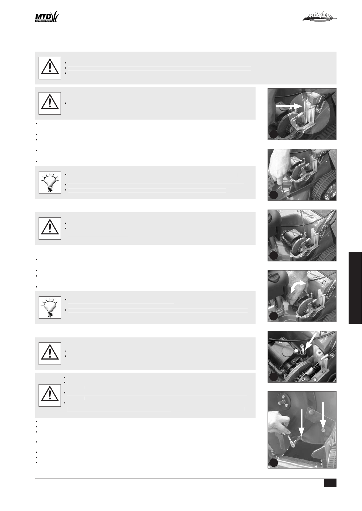
™
50
ESPAÑOL
Ajuste de la cadena de tracción
ADVERTENCIA
tracción.
Ajuste de la correa de tracción
tornillo de ajuste de la correa (figura 19).
Antes de ajustar la tensión de la correa, quite la hierba acumulada de la parte de abajo del
Asegure firmemente la segadora al inclinarla hacia arriba; con ello tendrá acceso a la parte
ADVERTENCIA
tire la correa.
19
18
20
17
21
22
Powered Walk Behind Mower - CE Part No. 04016218 Rev G © Copyright 12/2006

™
51
ESPAÑOL
Ajuste la correa de tracción por medio del tornillo de adaptador (consulte la sección “Ajuste de la correa de tracción”.)
Ajuste de los embragues
Afloje toda la cadena de tracción: desatornille el ajustador de la cadena (figura 24).
Afloje toda la correa de tracción: desatornille el ajustador de la correa (refer figure 25).
Tome nota de la señal (en la prominencia del plato de tracción interno) que sirve para alinearlo con el extremo de la
Tire hacia afuera los platos de tracción y leva de maniobra hasta que el plato interno quede libre de la chaveta de
a la señal de la que tomó
Antes de poner de nuevo el ensamblaje, limpie y engrase las levas del eje exterior del
25
26
24
27
28
29
23
Powered Walk Behind Mower - CE Part No. 04016218 Rev G © Copyright 12/2006

52
ESPAÑOL
MANTENIMIENTO (Continuación)
Cómo lubricar los trinquetes de tracción
• Levante las ruedas traseras y apóyelas sobre algo, para que no toquen el suelo.
•Quite los tapacubos y bloqueos de las ruedas (figura 30).
•Examine la parte interna del tapacubo a través del orificio. Si encuentra suciedad, deberá quitar y limpiar la rueda.
• Para quitar la rueda tendrá que quitar la placa de cierre que la mantiene unida al eje.
• Quite la rueda del eje y límpiela minuciosamente.
• Ponga unas gotas de aceite nuevo al extremo de la pieza de tracción, justo arriba de la arandela de retención
(figura 31). La pieza debe girar con facilidad; si éste no es el caso, repita el proceso.
• Ponga la rueda en su sitio, la arandela y asegúrela con una nueva placa de cierre.
• Si el tapacubo está limpio, gire la rueda hasta que la pieza de tracción esté a la vista a través del orificio.
• Ponga unas gotas de aceite limpio al extremo de la pieza de tracción (al igual que antes) y gire una o dos veces la rueda
para que penetre el aceite. La rueda debe girar con facilidad; si éste no es el caso, repita el proceso (figura 31).
• Ponga de nuevo los tapacubos y bloqueos de las ruedas.
• Utilice un atornillador delgado o parecido para destrabar el tapacubo de la rueda; cuide de
no doblarlo.
• Para quitar y poner las placas de cierre necesitará herramientas especiales. Si tiene dudas,
póngase en contacto con el distribuidor autorizado de Rover.
• Compre nuevas placas de cierre; éstas no se pueden usar de nuevo.
OPCIÓN DE BATERIA RECARGABLE (POWERSTART)
NOTA IMPORTANTE: La información en detalle acerca del mantenimiento de la batería se incluye en la sección de Instalación y en el siguiente cuadro.
• Consulte los apuntes sobre “Advertencia” y “Precaución” al principio de esta sección.
PRECAUCIÓN
Mantenga cargada la batería en forma completa.
30
31
Limpieza de la máquina usando el puerto de lavado opcional:
Coloque la máquina al exterior sobre una superficie plana
Fije la altura de corte a la posición alta (HIGH)
Con el motor detenido, conecte una manguera de jardín enchufable (saque primero la tapa), al puerto de
lavado ubicado en la cara interior de la cámara de corte. (Vea fig. 32)
Abra la manguera
Vuelva a la cortadora y haga marchar el motor a velocidad alta (FULL) durante 1 minuto.
Detenga el motor y cierre la manguera
Saque la manguera del puerto de lavado y vuelva a colocar la tapa
Inspeccione la parte inferior de la cortadora, si no estuviera completamente limpio use la manguera para
eliminar los desechos sobrantes.
32
™
Powered Walk Behind Mower - CE Part No. 04016218 Rev G © Copyright 12/2006

53
ESPAÑOL
Telar de conexiones
Antes de Después de Durante el Cada Cada
Componentes Medidas a tomar segar segar segado 5 horas 25 horas Factores a tomar en consideración
Aceite del motor
Aceite del motor
Ajuste
tracción bajo
Ajuste
Ajuste
Trinquetes
Asegúrese que la batería esté puesta
Tal como se indica o al no usarla por mucho tiempo.
™
Powered Walk Behind Mower - CE Part No. 04016218 Rev G © Copyright 12/2006

54
ESPAÑOL
ADVERTENCIA
Problema Posible causa Medida correctiva
™
Powered Walk Behind Mower - CE Part No. 04016218 Rev G © Copyright 12/2006

55
ESPAÑOL
Problema Posibles causas Medidas correctivas
tuosa
Problema Posibles causas Medidas correctivas
™
Powered Walk Behind Mower - CE Part No. 04016218 Rev G © Copyright 12/2006

™
56
NEDERLANDS
Als een punt onduidelijk is, neem dan contact op met een bevoegde Rover onderhoudsdealer.
WAARSCHUWING
WAARSCHUWING
VOORZICHTIG
- De Grasvanger installeren
- De Grasvanger verwijderen
- De Motor Starten
- De Motor Stoppen
- Hoe de zelfvoortdrijvende Transmissle te gebruiken
- Het reinigen van de onderkant van de maaimachine
- Het reinigen van de bovenkant van de maaimachine
- Het verstellen van de aandrijfkabel
- Het verwijderen van de beschermplaat voor het aandrijvingsframe
- Het aanbrengen van de beschermplaat voor het aandrijvingsframe
- Het smeren van de aandrijfketting
- Afstelling van de aandrijfketting
- Afstelling van de aandrijfriem
- Het vervangen van de aandrijfriem
- Het afstellen van de koppelingen
- Het smeren van de aandrijfpallen
Algemeen
Aanvullende reserveonderdelen
Powered Walk Behind Mower - CE Part No. 04016218 Rev G © Copyright 12/2006

™
57
NEDERLANDS
VEILIGHEIDSINSTRUCTIES
van de operateur door plaatselijke regelementen wordt beperkt.
VOORBEREIDINGEN
WAARSHUWING Benzine is zeer ontvlambaar. De volgende voorzorgsmaatregelen zijn nodig:
Vul de benzine in voordat U de machine start. U moet nooit de kap van de benzinetank afnemen of benzine bijvullen als
Als er wat benzine gemorst is moet U niet proberen om de motor te starten. Verwijder de machine van de plaats waar
Vervang alle beschadigde geluiddempers.
Voordat U de maaier gebruikt moet U altijd visueel inspekteren of de messen, de mesbouten en de snijmachine montage
vervangen worden in paren.
Waar mogelijk, gebruik de maaier niet op nat gras.
Als U op hellingen maait, zorg ervoor dat U niet uitglijdt.
Wees heel voorzichtig als U achteruit rijdt of de machine achteruit trekt.
Voordat U de motor start moet U alle messen en alle koppelingen ontkoppelen.
Voorzichtig zijn als U de motor start of de maaier inschakelt. Volg de instructies en houd Uw voeten niet te dicht bij de
Als U voor de ontlaadtrechter staat moet U de motor niet starten.
voordat U verstoppingen schoonmaakt of de trechter ontstopt.
voordat U de maaier inspekteert, schoonmaakt of aan de maaier begint te werken.
Als U tegen een vreemd voorwerp stuit, Inspekteer de maaier om te zien of er iets beschadigd is en dit goedmaken
voordat U de maaier opnieuw start en gebruikt.
Voordat U benzine bijvult.
Verlaag de setting van de regelklep terwijl de motor af loopt en als de motor een afsluitklep heeft, sluit dan de benzine af
Zorg er voor dat alle bouten, moeren en schroeven vastzitten om zeker te zijn dat de machine in een veilige en goede
vlam of vonk.
Voor de veiligheid moet U alle versleten en beschadigde onderdelen vervangen.
Als de benzinetank leeg gemaakt moet worden, moet U dat buitenshuis doen.
WAARSCHUWING
Powered Walk Behind Mower - CE Part No. 04016218 Rev G © Copyright 12/2006

™
58
NEDERLANDS
- Modellen 51, 61
- 20” (508 mm Snijbreedte)
- 112 Snijhoogtestelling
- Model 80
- 22” (560 mm Snijbreedte )
- 15 Snijhoogtestelling
- Modellen komen met een van een serie motoren (zie de handleiding voor motoren inbegrepen in de uitrusting.)
- Er is keus in de volgende modellen:
- Maaien van mulch
- Maaien met deflector
- Verreluchtreiniger
- Zelfvoortdrijvende Functie enz
- De zelf-rijdende functie
- enz.
- Details kunnen in deze handleiding inbegrepen zijn of in een aparte handleiding in de Maaieruitrusting.
Afsluitknoppen: door deze knoppen te draaien kan de handvatten of vastgesloten in bedieningsplaats zijn of opgevouwen
worden voor bewaring.
Voordat de handvat ontvouwen wordt, moet u er zeker van zijn dat de regelklepcontrole in
wordt; dit zal de motor aanslingeren totdat de volle rechtop positie is bereikt.
1
2
4
A
3
Powered Walk Behind Mower - CE Part No. 04016218 Rev G © Copyright 12/2006

™
59
NEDERLANDS
VERWIJDEREN VAN DE VERPAKKINGTOUWTJES VAN DE CONTROLEHENDELS
Verwijder en gooi de verpakkingtouwtjes weg die het remsnijmes en de hendel voor zelf-rijden
WAARSCHUWING
Als u de handleiding van de motorfabrikant niet heeft, gaat u dan naar de dichtstbijzijnde fabrikantagent voor een kopie
volgens de aanbevelingen van de motorfabrikant
VOORZICHTIG
Voorzichtig zijn als u het weggooit. Raadpleeg lokale regelingen over het weggooien van batterijen.
Alle gemorste electrolijten met een alkalijn oplossing neutraliseren.
WAARSCHUWING
zijn. (zie figuur 6).
zwart [-] aan zwart [-]).
Verwijder en gooi de verpakkingbanden weg die de hendel voor zelf-rijden aan het handvat vastklemmen voordat u probeert om de
WAARSCHUWING
vrijgezet om te kunnen draaien. Als de hefboom losgelaten wordt dan zet u de rem aan en de messen/motor stopt sne
WAARSCHUWING
WAARSCHUWING
6
5
Powered Walk Behind Mower - CE Part No. 04016218 Rev G © Copyright 12/2006

™
60
NEDERLANDS
Til de achterklep van de maaier op.
Til de grasvanger op zodat dit vrij is van de maaier en laat de achterklep zakken.
WAARSCHUWING
De maaiers die in deze handleiding worden behandeld hebben verschillende motoren die door verschillende fabrikanten gefabriceert waren. In de Mower Kit
Als u de handleiding van de motorfabrikant niet heeft, gaat u dan naar de dichtstbijzijnde fabrikantagent voor een kopie.
volgens de aanbevelingen van de motorfabrikant.
VOORZICHTIG
Wanneer u de motor in beweging zet of bedient, moet u uw vingers, tenen op afstand houden en omstanders uit de buurt houden.
Als de motor een Powerstarter optie heeft, moet u altijd de sleutel uit de ontstekingsschakelaar verwijderen. Bewaar dit op een
veilige plaats om ongeoorloofd starten van de motor te voorkomen.
WAARSCHUWING
), ( (snel),
(
)
verwijzen naar de staat van de startermotor
(uit),
(aan/start).
7
8
Powered Walk Behind Mower - CE Part No. 04016218 Rev G © Copyright 12/2006

™
61
NEDERLANDS
Zie en volg de instructies in de veiligheidsmaatregelen die in deze en geassocieerde handleidingen genoteerd zijn.
WAARSCHUWING
Als de hoogte of de dichtheid van het gras te groot is (om in het begin een grote motorsnelheid te handhaven) dan moet u eerst het
Voor de veiligheid laat de hendel voor zelf-rijden los en duw de machine wanneer u van
AANTEKENING: Het merendeel van problemen met maaimachines betreft de volgende zaken:
Voordat u enig onderhoud aan de maaimachine pleegt, overtuigt u zich ervan dat de motor stil staat en verwijder het kabel van de
Voor de Powerstart uitvoering: voordat u enig onderhoud aan de maaimachine gaat beginnen, verwijder de sleutel uit het contactslot.
Alle bechermingsplaten, messen, grasvangers en veiligheidslabels, als deze versleten of beschadigd zijn, moeten vervangen worden
Verwijder aangekoekt grasafval rondom het uitlaatgedeelte om te voorkomen dat er brandgevaar ontstaat.
WAARSCHUWING
Zorg ervoor dat er geen vuil of verontreiniging komt in de benzinetank, de olie vulbuis, de behuizing van het luchtfilter, de carburator
ventilatiegaten niet schoon zijn kan de motor oververhit raken en beschadigen.
Als u de maaimachine kantelt moet de bougie in de hoogste positie blijven om te voorkomen dat er olie in het luchtfilter en/of in de
Zorg ervoor dat de maaimachine droog en schoon is en dat deze opgeslagen wordt op een goed geventileerde plaats.
VOORZICHTIG
9
Powered Walk Behind Mower - CE Part No. 04016218 Rev G © Copyright 12/2006

™
62
NEDERLANDS
Als de motor loopt: open de afvoerklep nooit of kantel de maaimachine om de onderkant te wassen.
WAARSCHUWING
Terwijl de motor stilstaat, verwijder de grasvanger en open de grasafvoerklep.
Zie pagina 66 voor maaiers met een wasinlaat naar keuze
WAARSCHUWING
Trek de mesmoeren stevig aan (16 Nm).
Verwijder eerst al het grasafval dat aangekoekt is om de mesmoeren zodat de moersleutel
Als de bouten op de juiste wijze zijn aangebracht moeten de messen vrij kunnen draaien.
WAARSCHUWING
WAARSCHUWING
Als de overbrenging ook na het aanpassen blijft slippen, breng de maaimachine dan naar een erkende Rover dealer voor onderhoud.
VOORZICHTIG
10
11
Powered Walk Behind Mower - CE Part No. 04016218 Rev G © Copyright 12/2006

™
63
NEDERLANDS
Als de aandrijving pakt en de maaier begint te bewegen terwijl de ruimte groter is dan 55 mm, draai het duimwiel op het
Test de maaimachine uit op alle snelheden en zorg ervoor dat de aandrijving ontkoppelt als de gashendel losgelaten wordt
Als u nog steeds moeilijkheden ondervindt, ga dan naar uw dichtstbijzijnde erkende Rover dealer.
Zorg ervoor dat de kabel niet beschadigd is en recht is omdat dit de aandrijving kan
van een soepele en veilige bediening.
Til de plaat op en draai deze uit de machine zodat de bovenste overbrengingsonderdelen zichtbaar worden.
vastschroeft.
VOORZICHTIG
Zorg ervoor dat het smeermiddel niet in aanraking komt met de aandrijvingskoppelingen.
WAARSCHUWING
Terwijl u de buitenste koppelingsplaat (met de klok mee) draait, breng een gelijkmatige laag geschikt (niet uit een
vergemakkelijken. Breng slechts een geringe hoeveelheid smeermiddel aan op de tanden
16
15
14
12
13
Anti-clockwise
Powered Walk Behind Mower - CE Part No. 04016218 Rev G © Copyright 12/2006

™
64
NEDERLANDS
Afstelling van de Aandrijfketting
Zorg dat de ketting niet te strak zit.
VOORZICHTIG
WAARSCHUWING
Afstelling van de aandrijfriem
Zorg ervoor dat de riem niet te strak of te los zit om beschadiging en abnormale slijtage te
voorkomen.
VOORZICHTIG
Verwijder alle grasafval van de onderkant van de versnellingsbak naast de afstelveer voordat
VOORZICHTIG
Zet de maaimachine stevig vast als u deze kantelt om bij de onderkant te kunnen komen.
van de grond is als u de voorkant van de maaier optilt. Dit voorkomt beschadiging van de
WAARSCHUWING
Til de voorkant van de maaier op, draaiend op de achterwielen, totdat het benedenstuk van het duwframe de grond raakt en zet
19
18
20
17
21
22
Powered Walk Behind Mower - CE Part No. 04016218 Rev G © Copyright 12/2006

™
65
NEDERLANDS
Alleen als de maaimachine uitgerust is met een volledige schijf en messen is het nodig om de snij-assemblage te
verwijderen door de centrale bout en de drie bouten daaromheen los te draaien met geschikte moersleutels.
Als de maaier is uitgerust met de “Op één lijn Terugdraai Messen” optie, draai beide messen dan naar achteren totdat de
Als de maaier is uitgerust met de “Op één lijn Terugdraai Messen” optie, draai de messen dan terug zodat ze in lijn zijn
Verwijder het aangekoekte grasafval van de schroefkoppen van de riembeschermingsplaat
worden gemonteerd.
Aantekening: Deze procedure is alleen nodig in het geval dat de kabelafstelling niet in staat is om voor voldoende
VOORZICHTIG
Afstelling ‘I’ wordt in het algemeen gebruikt voor een nieuwe aandrijfplaat terwijl afstelling
Als de kabelaanpassing onvoldoende is wanneer de binnenste aandrijfplaat in positie ‘III’ is
25
26
24
27
28
29
23
Powered Walk Behind Mower - CE Part No. 04016218 Rev G © Copyright 12/2006

66
NEDERLANDS
ONDERHOUD (vervolg)
Het smeren van de aandrijfpallen
• Breng de achterwielen van de grond en ondersteun deze.
• Verwijder de achterste wieldoppen en wielplugs (zie afbeelding 30).
•Controleer de binnenkant van de wielnaaf door het gat van de wielplug. Als u verontreiniging vindt moet het wiel
afgenomen worden en worden schoon gemaakt.
• Om het wiel te verwijderen moet u de palplaat afnemen die het wiel aan de as bevestigd houdt.
• Neem het wiel van de as en reinig het grondig.
• Gebruik schone motorolie, en breng een paar druppels olie aan op het uiteinde van de van de overbrengingsdrijfwerk
boven de bevestigingsplaat en draai het drijfwerk zodat de olie kan binnendringen (zie afbeelding 31). Het drijfwerk
moet vrij kunnen draaien, als het dat niet doet herhaal dan de genoemde procedure.
• Breng het wiel en de plaat weer aan en maak vast met een nieuwe palplaat.
•Als de wielnaaf schoon is, draai het wiel dan todat u het overbrenginsdrijfwerk kunt zien door het gat voor de wielplug.
• Gebruik schone motorolie, breng een paar druppels olie aan op het uiteinde van het drijfwerk (zie hierboven) en draai het
wiel een keer of twee om de olie de gelegenheid te geven om binnen te dringen. Het wiel moet nu vrij kunnen draaien, als
het dat niet doet, herhaal dan de procedure (zie afbeelding 31).
• Breng de wielpluggen en de wieldoppen weer aan.
• Gebruik een schroevendraaier met een smalle bek, of iets soortgelijks, tussen de wieldop en
het wiel om de wieldop van het wiel te lichten, wees voorzichtig en buig het niet te ver.
• Palplaten hebben speciaal gereedschap nodig om ze te verwijderen en ze weer aan te
brengen. Als u niet zeker bent raadpleeg dan uw dichtstbijzijnde bevoegde Rover dealer.
• Koop nieuwe palplaten voordat u de wielen afneemt omdat ze niet opnieuw gebruikt
kunnen worden.
DE POWERSTART OPTIE
N.B. Het onderhoud van de accu wordt behandeld in het installatie gedeelte en in het volgende schema.
• Houdt rekening met de algemene “Waarschuwing” en “Voorzichtig” aantekeningen aan het begin van het onderhoudshoofdstuk.
VOORZICHTIG
Zorg ervoor dat de accu volledig geladen is om zeker te zijn van een lange gebruiksduur.
30
31
Maaier schoonmaken met gebruik van een optionele was opening:
Plaats de maaier buiten op een horizontale oppervlakte
Zet de snijhoogte op de HOOG snijpositie
Bevestig een tuinslang met knipsluiting, met de motor af
(verwijder eerst de dop), aan de was opening aan de binnenkant van de smijkamer (zie afbeelding 32)
Zet de tuinslang aan
Ga terug naar de maaier, zet de motor aan en laat 1 minuut OP VOLLE SNELHEID lopen.
Zet de motor en de tuinslang allebei af.
Verwijder de tuinslang van de was opening en doe de dop er weer op.
Bezie de onderkant van de maaier, en gebruik de tuinslang om de laatste overblijfselen te verwijderen als zij
niet geheel schoon is.
32
™
Powered Walk Behind Mower - CE Part No. 04016218 Rev G © Copyright 12/2006

67
NEDERLANDS
Als de binnenste kabel strak zit, doe er olie op.
Als u twijfelt of als de motor niet werkt,
wanneer toegepast
Voor het Na het Tidjens het Elke Elke
Onderdelen Actie maaien maaien maaien 5 uur 25 uur Bijzonderheden
van de fabrikant voor instructies
van de fabrikant voor instructies
van de fabrikant voor instructies
van de fabrikant voor instructies
van de fabrikant voor instructies
Aandrijfkabel
Afstellen
Aandrijf-assemblage
Aandrijfketting
Afstellen
Aandrijf riem
wanneer toegepast
Afstellen
Verwijder, maak schoon en controleer
voor de aandrijfriem
Aandrijfpallen
wanneer toegepast
Accu
wanneer toegepast
wanneer toegepast
™
Powered Walk Behind Mower - CE Part No. 04016218 Rev G © Copyright 12/2006

68
NEDERLANDS
ALGEMEEN
Als u onderdelen vervangt, gebruik dan altijd originele Rover onderdelen.
WAARSCHUWING
Voor problemen met de motor en herstelwerkzaamheden, gebruik de handleiding van de fabrikant van de motor.
VOORZICHTIG
Als u herstelwerkzaamheden uitvoert, raadpleeg dan de van toepassing zijnde instructies in deze handleiding.
Probleem Mogelijke oorzaken Herstelwerkzaamheid
tijdens maaien
zijn vuil of geblokkeerd
™
Powered Walk Behind Mower - CE Part No. 04016218 Rev G © Copyright 12/2006

69
NEDERLANDS
Probleem Mogelijke oorzaken Herstelwerkzaamheid
Probleem Mogelijke oorzaken Herstelwerkzaamheid
versnellingsbak is gebroken
voor de aandrijfkabel
versleten
wanneer het drijfwerk
™
Powered Walk Behind Mower - CE Part No. 04016218 Rev G © Copyright 12/2006

™
70
ITALIANO
AVVERTIMENTO
AVVERTIMENTO
ATTENZIONE
AVVERTENZE
- Installare il raccoglitore dell’erba
- Rimuovere il raccoglitore dell’erba
- Avviare il motore
- Arrestare il motore
Taglio e raccolta dell’erba
- Utilizzare la trasmissione a propulsione autonoma
- Pulire la parte inferiore della falciatrice
- Pulire la parte superiore della falciatrice
- Regolare il cavo di trasmissione
- Rimuovere il coperchio della struttura di trasmissione
- Rimettere il coperchio della struttura di trasmissione
- Lubrificazione della catena di trasmissione
- Regolazione della catena di trasmissione
- Regolazione della cinghia di trasmissione
- Rimettere della cinghia di trasmissione
- Regolare la frizione
- Lubrificare i denti di trasmissione
Powered Walk Behind Mower - CE Part No. 04016218 Rev G © Copyright 12/2006

™
71
ITALIANO
AVVERTENZE
vigenti pongano restrizioni per l’età dell’operatore.
ATTENZIONE – Il carburante è altamente infiammabile. Prendere le seguenti precauzioni:
Aggiungere carburante prima di accendere il motore. Non togliere mai il coperchio del serbatoio del carburante o
Assicurarsi sempre di mantenere una buona stabilità sui pendii.
Avviare il motore o accendere la falciatrice con cautela secondo le istruzioni e tenendo i piedi ben lontani dalla(e) lama(e).
AVVERTIMENTO
Powered Walk Behind Mower - CE Part No. 04016218 Rev G © Copyright 12/2006

™
72
ITALIANO
- Modelli 51, 61
- 20” (508mm Ampiezza di taglio)
- 12 impostazioni di altezza di taglio
- Modello 80
- 22” (560mm Ampiezza di taglio)
- 15 impostazioni di altezza di taglio
- Opzioni sono disponibili (e possono essere aggiunte) ai modelli descritti sopra es.
- Falciatura di pacciame
- Falciatura deflettore
- Depuratore dell’aria distaccato
- Funzione avviamento a motore
- Funzione autopropulsione
- ecc.
- I dettagli vengono discussi in questo manuale o in un altro manuale compreso nel kit della falciatrice.
verticale.
Allentare i due dadi (B) alla base dei manubri su entrambi i lati della falciatrice con una chiave inglese 1/2” AF (figura 4).
Avvisare il rivenditore dei pezzi mancanti il prima possibile.
1
2
4
A
3
Powered Walk Behind Mower - CE Part No. 04016218 Rev G © Copyright 12/2006

™
73
ITALIANO
AVVERTIMENTO
ATTENZIONE
AVVERTIMENTO
Togliere le due viti dalla scatola di supporto della batteria, ruotare la batteria e il coperchio in avanti ed esporre i
AVVERTIMENTO
AVVERTIMENTO
AVVERTIMENTO
6
5
Powered Walk Behind Mower - CE Part No. 04016218 Rev G © Copyright 12/2006

™
74
ITALIANO
Afferrare il raccoglitore dell’erba per la manopola superiore e posizionarlo contro la parte posteriore della falciatrice
Afferrare la manopola superiore del raccoglitore dell’erba e sollevare.
Alzare il piano posteriore della falciatrice per rilasciare il raccoglitore dell’erba.
AVVERTIMENTO
Afferrare la leva per l’altezza di taglio (A) e tirarla verso l’esterno per rilasciare la leva dalla cremagliera (B) (figura 8).
Avviare il motore
ATTENZIONE
AVVERTIMENTO
( (), (),
(
valvola dell’aria del motore
)
( ().
Arrestare il motore
7
8
Powered Walk Behind Mower - CE Part No. 04016218 Rev G © Copyright 12/2006

™
75
ITALIANO
AVVERTIMENTO
Accendere il motore ed impostare il motore ad alta velocità.
Tenere il manico alla velocità di trasmissione desiderata e rallentare o accelerare a seconda delle condizioni.
Assicurarsi sempre che l’apparecchiatura sia in buone condizioni di funzionamento.
Assicurarsi sempre che il motore sia spento e rimuovere il filo della candela prima di tentare di riparare la falciatrice.
AVVERTIMENTO
Assicurarsi che non ci siano accumuli di scarto nei fori di ventilazione adiacenti allo starter di contraccolpo. Il motore potrebbe surriscaldarsi e
venire danneggiato se questi fori non sono puliti.
Assicurarsi che la falciatrice sia asciutta e pulita e riposta in area ben ventilata.
ATTENZIONE
9
Powered Walk Behind Mower - CE Part No. 04016218 Rev G © Copyright 12/2006

™
76
ITALIANO
AVVERTIMENTO
AVVERTIMENTO
Togliere il sostegno del piano, chiudere il piano di scarico e reinserire il filo della candela.
AVVERTIMENTO
AVVERTIMENTO
ATTENZIONE
10
11
Powered Walk Behind Mower - CE Part No. 04016218 Rev G © Copyright 12/2006

™
77
ITALIANO
Avviare la falciatrice nella posizione di disinnesto.
volta) in senso antiorario fino a quando si innesta (figura 13).
Assicurarsi che il cavo non sia danneggiato o attorcigliato, ciò potrebbe influire sulla
Alzare il coperchio e girarlo fuori dalla falciatrice per rendere visibili le parti superiori della trasmissione.
Assicurare che l’anello sollevato sulla sezione di ottone del cavo di trasmissione sia sistemato nel solco della struttura di supporto
ATTENZIONE
tenerlo orizzontalmente con una mano (figura 15).
Avvitare saldamente la guarnizione posteriore sopra il cavo.
AVVERTIMENTO
trasmissione”) per rendere visibile la catena.
trasmissione).
16
15
14
12
13
Anti-clockwise
Powered Walk Behind Mower - CE Part No. 04016218 Rev G © Copyright 12/2006

™
78
ITALIANO
ATTENZIONE
Assicurarsi che il motore e la marmitta siano freddi prima di tentare di regolare la catena
AVVERTIMENTO
ATTENZIONE
Togliere il coperchio della struttura di trasmissione (vedere la sezione “Rimuovere il coperchio della struttura di trasmissione”)
ATTENZIONE
AVVERTIMENTO
Togliere il coperchio della struttura di trasmissione (vedere la sezione “Rimuovere il coperchio della struttura di trasmissione”).
Abbassare il manubrio e rimuovere il raccoglitore dell’erba e appoggiare le ruote posteriori su blocchi di 50mm (min) di altezza
Alzare la parte anteriore della falciatrice sulle ruote posteriori fino a che il manubrio più basso viene a contatto col suolo e
19
18
20
17
21
22
Powered Walk Behind Mower - CE Part No. 04016218 Rev G © Copyright 12/2006

™
79
ITALIANO
Abbassare la falciatrice così tutte le ruote appoggiano sul terreno.
trasmissione”).
ATTENZIONE
Togliere il coperchio della struttura di trasmissione (vedere la sezione “Rimuovere il coperchio della struttura di
trasmissione”) per rendere visibili i piani della frizione e altre regolazioni.
Allentare la catena di trasmissione completamente svitando il regolatore di catena (figura 24).
Allentare la cinghia di trasmissione completamente svitando il regolatore della cinghia di trasmissione (figura 25).
Alzare leggermente il bordo esterno dell’albero motore e far scivolare il sostegno dell’albero motore di uscita (figura 28).
Annotare quale segno (sul punzone del piano di trasmissione interna) è allineato con il perno del cilindro di blocco
trasmissione”).
25
26
24
27
28
29
23
Powered Walk Behind Mower - CE Part No. 04016218 Rev G © Copyright 12/2006

80
ITALIANO
MANUTENZIONE (continua)
Lubrificare i denti di trasmissione
•Sollevare le ruote posteriori dal suolo.
• Rimuovere i coperchi centrali ed i tasselli delle ruote (figura 30).
• Esaminare l’interno della parte centrale della ruota attraverso il foro. Se vi è della sporcizia, la ruota dovrebbe essere
rimossa e pulita.
• Per rimuovere la ruota, togliere il piano del dente di arresto che fissa la ruota all’asse.
• Spostare la ruota dall’asse e pulire bene.
• Applicare alcune gocce di puro olio per motore al bordo del cambio di trasmissione sopra la rosetta di sostegno e
ruotare il cambio per permettere all’olio di penetrare (figura 31). Il cambio dovrebbe girare liberamente, altrimenti
ripetere la procedura sopra indicata.
• Sostituire la ruota, la rosetta e stringere con un nuovo piano del dente di arresto.
•Se il centro della ruota è pulito, girare la ruota fino a che il cambio di trasmissione è visibile attraverso il foro.
• Applicare alcune gocce di puro olio per motore al bordo del cambio di trasmissione (come sopra) e girare la ruota una
o due volte per permettere all’olio di penetrare. La ruota dovrebbe girare liberamente, altrimenti ripetere la procedura
(figura 31).
• Sostituire i tasselli ed i coperchi centrali delle ruote.
• Utilizzare un cacciavite a punta fine o simile fra il fulcro e la ruota per fare leva sul fulcro,
stando attenti a non piegarlo eccessivamente.
• I piani dei denti di arresto necessitano di particolari at trezzi per essere rimossi e sostituiti.
Se non siete sicuri, contattare il vostro concessionario autorizzato Rover.
• Acquistare nuovi piani di denti di arresto prima di rimuovere le ruote in quanto non sono
riutilizzabili.
OPZIONE AV VIAMENTO A MOTORE
N.B Dettagli sulla manutenzione della batteria sono riportati nella sezione di preparazione e nella tabella che segue.
• Fare riferimento alle note di “Avvertimento” e “Attenzione” all’inizio di questa sezione.
ATTENZIONE
Mantenere la batteria carica per assicurare prestazioni di massima durata.
30
31
Pulizia del tosaerba usando l’apposita apertura per il lavaggio:
Poggiare il tosaerba su una superficie piatta all’aperto.
Impostare l’altezza di taglio sulla posizione di taglio ALTO.
Con il motore spento, collegare un tubo flessibile da giardino con un accessorio di aggancio (togliere dapprima il
tappo) all’apposita apertura per il lavaggio situata sulla superficie interna della camera di taglio (cfr. fig. 32)
Aprire il rubinetto cui è collegato il tubo flessibile.
Tornare al tosaerba e avviare il motore facendolo operare a PIENA velocità per 1 minuto.
Spegnere il motore e chiudere il rubinetto dell’acqua cui è collegato il tubo flessibile.
Togliere il tubo flessibile dall’apertura per il lavaggio e rimettere il coperchio.
Ispezionare la parte inferiore del tosaerba e, se non completamente pulita, usare il getto d’acqua del tubo
flessibile da giardino per togliere eventuali detriti rimanenti.
32
™
Powered Walk Behind Mower - CE Part No. 04016218 Rev G © Copyright 12/2006

81
ITALIANO
Autorizzato se in dubbio o non funzionante
Telaio cablaggio
Prima di Dopo la Durante la Ogni Ogni
Componenti Azione falciare falciatura falciatura 5 ore 25 ore Considerazioni
trasmissione (dove in dotazione)
trasmissione
Assicurare che la batteria sia saldamente sostenuta
A seconda della necessità ma principalmente dopo lunghi periodi di inattività
™
Powered Walk Behind Mower - CE Part No. 04016218 Rev G © Copyright 12/2006

82
ITALIANO
AVVERTIMENTO
ATTENZIONE
Altri manuali possono essere forniti con la vostra falciatrice relativi a specifiche opzioni. Utilizzare questi manuali per riparazione di guasti specifici a tali opzioni.
Problema Possibili Cause Azione Correttiva
Taglio irregolare
™
Powered Walk Behind Mower - CE Part No. 04016218 Rev G © Copyright 12/2006

83
ITALIANO
Problema Possibili Cause Azione Correttiva
Problema Possibili Cause Azione Correttiva
trasmissione è rotto
trasmissione sono rotti/consumati
trasmissione
™
Powered Walk Behind Mower - CE Part No. 04016218 Rev G © Copyright 12/2006

84
SPARE PARTS VIEWS
BASE SPARE PARTS
No. Part No. Description Qty
1 A 1613 5 Base- 20” Push 1
1 A 16 0 7 0 Base- 20” Self propelled 1
1 A 161 76 Base- 22” Self propelled 1
2 A 03 510 Height adjustment rack- 20” only 1
2 A 16 0 81 Height adjustment rack- 22” only 1
3 A 0 3126 Flap bush 2
4 A 03456 Rear flap 1
5 A 033 25 Flap spring 1
6 A 03455 Handle- flap 1
7 A03306 Flap rod 1
8 A 2 9 0 11 2 Rivet- flap handle 2
9 A04164 Rivet- rack 2
10 A 1618 0 Chain case- dummy 20” push only 1
10 A 16 0 6 6 Chain case- 20” & 22” s/prop.only 1
11 A 16 216 Infil piece- 20” push only 1
12 A04040 Rivet- 20” push only 1
13 A04158 Screw- M5 x 20 2
14 A04099 Washer 2
15 A04163 Nyloc nut- M5 2
16 A 10 381 Axle retainer- 20” CE push 1
16 A 03877 Axle retainer- 20” US push 1
16 A 033 83 Axle retainer- 20” & 22” local & CE SP 1
16 A 038 78 Axle retainer- 20” & 22” US SP 1
17 A 2 9 0 11 2 Rivets- rear axle retainer- 20” push 4
18 A 10622 Rear wheel assembly- 20” push 2
19 A 0335 3 Wheel bearing 8
20 A 3 731 09 Tension washer 4
21 A03 092 Ratchet plate 4
22 A03414 Hub cap- chrome 4
22 A 162 3 4 Hub cap- black 4
23 A 16 01 4 Wheel seal 2
24 A10 649 Rear axle assembly- 20” push 1
25 A 16 2 2 0 Rear axle bush- 20” push 2
25 A 16 2 9 4 Rear axle bush- 20” & 22” s/prop 2
26 A10 284 Height adjustment lever- 20” only 1
26 A 106 35 Height adjustment lever- 22” only 1
27 A 03 336 Plate 1
28 A 0 2 11 8 Rivets- height adj. lever 2
29 A0325 0 Handle grip 1
30 A 16 0 14 Wheel seal- 20” push only 2
31 A04164 Rivet- rack 22” s/prop. only 1
32 A03516K Axle hook kit 2
33 A 10603 Front axle assy- 20” CE & US Mulch 1
33 A 105 27 Front axle assy- 20” Push & S/prop 1
33 A 10638 Front axle assy- 22” S/prop 1
33 A106 48 Front axle assy- 22” CE & US mulch 1
34 A03450 Front axle bush- 20” push & s/prop 2
34 A 03 674 Front axle bush- 22” s/prop 2
35 A16005 Disc- 20” push & s/prop. only 1
36 A 03830 Blade- standard 20” suits item 35 4
36 A 03930 Blade- mulch 20” suits item 35 4
37 A00673K Blade bolt, nut & washer kit- suits item 35 2
38 A03999 Bar blade holder- 20” only 1
38 A 1617 3 Bar blade holder- 22” only 1
39 A 16 10 8 Blade- 22” 2
39 A 16238 Blade- 22” CE & US only 2
40
A04139K Blade bolt, nut & washer kit- suits item 38 1
41 A0 555K Centre bolt kit 1
42 A01486 Disc boss 1
43 A 02 051 Woodruff key 1
44 A106 47 Conbar- standard 20” push & s/prop. 1
44 A10644 Conbar- standard 22” s/prop. 1
45 A 10687 Conbar complete assy- 20” mulch 1
45 A 10710 Conbar complete assy- 22” mulch 1
45 A 1 0 7 15 Conbar complete assy- 20” China 1
46 A 10684 Conbar front assy.- 20” mulch 1
46 A 1 0 7 11 Conbar front assy.- 22” mulch 1
47 A10 686 Conbar rear assy.- 20” mulch 1
47 A 10 713 Conbar rear assy.- 22” mulch 1
47 A1070 8 Conbar rear assy.- 20” China 1
48 A04117 Cuphead bolt 1
49 A02030 Washer 1
50 A03998 Handle 1
No. Part No. Description Qty
51 A02223 Nut 1
52 A 1 0 6 21 Front wheel assy.- 20” push & s/prop. 2
52 A10 622 Front wheel assy.- 22” s/prop. 2
53 A 2 5 0 1116 Ratchet plate 2
54 A 03995 Logo 1
55 A04171 Rivets- logo 2
56 A 16 076 Conbar spring- 20” push & s/prop. 1
56 A 16 219 Conbar spring- 22” s/prop. 1
57 A 0 2127 Engine Bolt- B&S 3
57 A 0 2127 Engine Bolt- Honda GCV 160 3
57 A04145 Engine Bolt- Honda GXV 140 3
58 A 02 012 Washer- Flat- Honda GXV 140 3
59 A 0 20 31 Washer- shakeproof Honda GXV 140 3
60 A 16 137 Nose comb- 20” & 22” CE & US only 1
61 A 0 4111 Screw- 20” & 22” CE & US only 2
62 A 03743 Label- warning CE only 1
63 A03492 Label- Noise CE only 1
64 A 03934 Label- warning US only 1
65 A 0 3874 Label- danger US only 1
66 * Label- Model 1
67 A04173 O-Ring 1
68 A 16 3 02 Washport - plastic 1
69 A04038 Washer- 04.15 x 15 x 18g.flat 2
70 A 0 2175 Rivet- 73 AS 5-5 2
™
Powered Walk Behind Mower - CE Part No. 04016218 Rev G © Copyright 12/2006

85
No. Part No. Description Qty
A03802
A03809
A 16174
A 16 0 5 0
A 161 8 5
A02849K
A 033 0 7
A02260
A02223
A 0351 8
A 1239 2
A 03556
A 03559
A 0355 8
A 03 610
A 0356 3
A 0 216 3
A02002
A 02083
A 02 012
A 111 0 2
A03430
A 033 26
Throttle cable- 20” B&S CE
A 10 6 41
Throttle cable- 20” Honda GXV
A 10718
Throttle cable- 22” B&S CE
A 1 07 19
Throttle cable- 22” Honda GXV
A 1 0 7 21
Throttle cable- 22” B&S US
A00950K
Throttle control assembly- briggs
A10016K
Throttle control assembly- Honda
A04060
A 0356 5
A 0356 0
A 0 767 9
A 03557
A 161 4 2
A02028
A 02083
A04045
A 020 81
A 02 235
A 161 33
A 161 8 3
A 0 2 5 21
A 10 717
A1 0523
A 10524
A03732
A 03739
A 037 47
A 0362 2
A 03756
A 03933
Throttle block
A16006
Throttle control assembly- US
A 0 2 216
A04114
A 16 2 33
A 161 8 4
A04083
A 03 733
A03732
A 026 68
A 026 68
A 03938
A 037 74
™
Powered Walk Behind Mower - CE Part No. 04016218 Rev G © Copyright 12/2006

86
SPARE PARTS VIEWS
SELF PROPELLED SPARE PARTS
No. Part No. Description Qty
1 A 106 24 Wheel assembly- 20” 2
1 A 10 669 Wheel assembly- 22” 2
2 A 0 3381 Cover Plate- 20” LH 1
2 A 0 338 0 Cover Plate- 20” RH 1
2 A16045 Cover Plate- 22” Common 2
3 A 0 3353 Wheel bearing 4
4 A03414 Hub cap 2
5 A3521047 Plug 2
6 A 3 7310 9 Tension washer 2
7 A03092 Ratchet plate 2
8 A 16 0 75 Belt cover 1
9 A 16 0 65 Engine pulley 1
10 A 16 0 7 9 Gearbox pulley 1
11 A 02 051 Woodruff key 1
12 A04075 Grub screw- 1/4” x 3/8” unc 2
13 A04073 Roll pin- gearbox pulley 5 x 40 1
14 A04167 Setscrew- M5 x 16 hex. 2
15 A04099 Washer- 3/16” x 3/4” x 16g 2
16 A 10639 Rear axle assembly- complete 20” 1
16 A 10 637 Rear axle assembly- complete 22” 1
17 A 16 2 9 4 Axle bush 2
18 A 1028 4 Height adjustment lever- 20” 1
18 A 1 0635 Height adjustment lever- 22” 1
19 A03250 Handle grip 1
20 A 0 3336 Packing plate 1
21 A 0 211 8 Rivets- 1/4” x 3/4” 2
22 A02090 Circlip 4
23 A 0 3373 Pawl retainer 4
24 A 0 337 2 Pawl 2
25 A 0 3370 Pinion- LH 1
26 A 033 61 Bearing 2
27 A 033 71 Pinion- RH 1
28 A 1613 1 Drive frame 1
29 A10640 Gearbox assembly 1
30 A 16 0 63 Frame cover 1
31 A 16 0 61 Cap- spring 1
32 A 16 0 6 4 Spring- gearbox 1
33 A 10636 Clutch plate assembly- incl. item 34 1
34 A 033 90 Clutch lining 1
35 A 163 2 2 Spring- clutch plates 1
36 A 10 170 Clutch plate assembly- drive 1
37 A 16 05 6 Thrust washer 1
38 A 16323 Spring- cam lever 1
39 A 16 05 7 Cam lever 1
40 A16060 Bearing retainer and cam 1
41 A 1613 9 Thrust cap 1
42 A04165 Screw- M6 x 12 csk. Cap screw 1
43 A 16 0 6 2 Bearing cap 1
44 A 0 2 111 Nyloc nut- M6 2
45 A04162 Screw- M6 x 60 1
46 A 0 4161 Screw- M6 x 70 1
47 A04091 Screw- M5 x 16 3
48 A04157 Roll pin- gearbox shaft 1
49 A04163 Nyloc nut- M5 9
50 A04160 Screw- M5 x 40 3
51 A 1633 7 Label- Caution Drive Belt Tension 1
5
2 A 16 0 6 6 Chain case 1
53 A 16 06 9 Wedge 1
54 A 16 0 68 Chain tensioner 1
55 A 16 0 71 Axle supports 2
56 A 16 0 7 2 Sprocket- 12 tooth (
suits 1/8” x 3/4” roll pin
) 1
56 A 163 6 0 Sprocket- 12 tooth (
suits 5/32” x 3/4” roll pin
) 1
57 A 0 3394 Felt seal 1
58 A 02069 Roll pin- drive shaft (
suits 1/8” x 3/4” roll pin
) 1
58 A 0 4174 Roll pin- drive shaft (
suits 5/32” x 3/4” roll pin
) 1
59 A 16 0 5 8 Drive shaft- 20” (
suits 1/8” x 3/4” roll pin
) 1
59 A 1617 9 Drive shaft- 22” (
suits 1/8” x 3/4” roll pin
) 1
59 A 163 61 Drive shaft- 22” (
suits 5/32” x 3/4” roll pin
) 1
60 A 0339 1 Mount bracket 1
61 A 033 83 Rear axle retainer- CE 1
61 A 03878 Rear axle retainer- US 1
62 A 03393 Drive shaft shield- CE 1
62 A 03879 Drive shaft shield- US 1
No. Part No. Description Qty
63 A 16 07 8 Chain- 3/8” x 58 pitch ASA incl. con link 1
64 A 161 8 2 Spacer- engine pulley 20” only 1
65 A 03382 Seal- rear wheel 20” only 2
66 A0 20 81 Setscrew- 1/4” x 1-3/4” unc. hex. 2
67 A02027 Washer- 1/4” spring 5
68 A02001 Nut- 1/4” hex. 5
69 A02146 Setscrew- 1/4” x 3/4” unc. hex. 2
70 A 02078 Setscrew- 1/4” x 1/2” unc. hex. CE only 2
71 A 16 07 7 Belt- Dayco SPZX-612 20” only 1
71 A 16 217 Belt- Dayco SPZX-670 22” only 1
72 A02027 Washer- 1/4” spring CE only 2
73 A02001 Nut- 1/4” unc. hex. CE only 2
75 A 0 2235 Nyloc nut- 1/4” unc- 20” US only 4
76 A 0 2 214 Setscrew- 1/4” x 5/8” unc. hex. 20” US 4
77 A03604 Extension- CE mowers only 1
78 A 038 81 Backing plate- 20” US only 1
79 A 03883 Rubber flap- 20” only 1
79 A 162 35 Rubber flap- 22” only 1
80 A04158 Screw- M5 x 20 4
81 A 02 078 Setscrew- 1/4” x 1/2” unc. hex. 1
82 A 16 2 39 Label- Self propelled cover 1
83 A 0 2169 Setscrew- 1/4” x 1” unc. 22” US only 4
84 A 162 8 4 Backing plate- 22” US only 2
85 A 02 235 Nyloc nut- 1/4” unc. 22” US only 4
86 A02001 Nut- 1/4” unc. hex. 22” US only 4
87 A02027 Washer- 1/4” spring 22” US only 4
88 A04169 Nut- M5 hex. 2
89 A02 234 Washer- 3/16” shakeproof 2
90 A 0 2235 Nyloc nut- 1/4” hex. 2
91 A04013 Washer- 3/4” x 1- 1/2” flat 1
™
Powered Walk Behind Mower - CE Part No. 04016218 Rev G © Copyright 12/2006

87
ANCILLARY SPARE PARTS
No. Part No. Description Qty
J10144
A034 47
A 033 24
A 0 2 216
A 0 2175
A 0 216 3
A 0 219 3
A04083
A10 689
A 10 714
A 03901
A 03 914
A 2 9 0 119 5
A 0 2175
A 0 219 2
A03894
A 03928
J10 605
A03743
A 038 75
™
Powered Walk Behind Mower - CE Part No. 04016218 Rev G © Copyright 12/2006

88
™
SPARE PARTS VIEWS
HANDLEBARS AV
No. Part No. Description Qty
1 A16875 20” Upper Handlebar- Anti Vibration 1
1 A16872 22” Upper Handlebar- Anti Vibration 1
2 A16869 18-22” Middle Handlebar Anti Vibration 1
3 A16050 Lower Handlebars-20” only 1
3 A16185 Lower Handlebars-20” Prof & 22” 1
4 A16873 20” & 22” Brace- Anti Vibration 1
5 A16877 Anti Vibration Mounts 4
6 A04188 M8 Nyloc Nut 8
7 A04206 M8 Washer 8
8 A04221 M6x40mm Button Head Screw Cap 2
9 A04202 M6 Nyloc Nut 2
10 A04205 M6 Washer 2
11 A16878 Anti Vibration End Plugs 2
12 A03126 Bush 2
13 A02849K Cam lock- incl. item 14,15,16 2
14 A03307 Draw bolt- cam lock Incl. in item 13 2
15 A02260 Roll pin- cam lock Incl. In item 13 2
16 A02223 Nyloc nut- 5/16” unc. Incl. in item 13 2
17 A03430 Lever stop plate 1
18 A10702
Throttle cable 20”- 1235mm (Outer Cable Length)(Suits i5000) 1
18 A10765 Throttle cable 22”- 1340mm (Outer Cable Length)(Suits i5000) 1
19 A10720K Throttle control assembly/Choke 1
20 A02028 Setscrew- 5/16” x 5/8” -20” only 4
20 A02083 Setscrew- 5/16” x 3/4” -20” Prof & 22” 4
21 A04045 Flanged nut- 5/16” unc 4
22 A10523 Brake lever assembly- 20” push 1
23 A03732 Cable clip- all models 1
24 A03747 Label- blade brake 1
25 A16233 Brake cable- 20” 1
25 A16184 Brake cable- 22” 1
26 A04083 Screw- 10 x 19 pan head 1
27 A02668 Cable tie- self propelled 1
28 A16324 Soft grips 2
29 A02081 Setscrew- 1/4” x 1-3/4” unc 1
30 A02235 Nyloc nut- 1/4” unc 1
31 A16177 Clutch cable- 20” 1
31 A16378 Clutch cable- 22” 1
32 A09146 Spacer 2
33 A10717 Clutch lever assembly 1
34 A10524 Brake lever assembly- 20 & 22” s/prop. 1
35 A03739 Handle grip 1
36 A16391 Spring- clutch cable 1
™
Powered Walk Behind Mower - CE Part No. 04016218 Rev G © Copyright 12/2006

89
GB
Dealer Product
D
Händler Produkt
F
Fabricant Produit
SP
Vendedor Producto
NL
Handelaar Product
1
Distributore Prodotto
These machines are covered by one or more of the following
Australian. 131504, 134850, New Zealand. 4023205
Australian. 713852, 729036, 745750, New Zealand. 330293,
Australian. & PCT Patent application:
Australia. 1923/2001
MTD Products Australia
PO Box 376
Dandenong Victoria 3175
Australia
, Australian. 2007200377
™
Powered Walk Behind Mower - CE Part No. 04016218 Rev. I ©Copyright 11/2010
Powered Walk Behind Mower - CE Part No. 04016218 Rev G © Copyright 12/2006
 Loading...