

Page 1
OMNIA-6
USER’S GUIDE
PROFESSIONAL ANALOG & DIGITAL
CATV “QAM-DVB-C” PALM-TOP ANALYZER
FREQUENCY: 5/870 MHz – LEVEL/POWER: 15 to 126 dBuV
(-45 to +66 dBmV / -93 to +18 dBm)
DRAFT VERSION
Subject to change without notice
Page 2

Omnia-6 User’s Guide Draft Version
2
Code: UG-OMNIA-6
Title: OMNIA-6 User’s Guide
Edition: 1.60-6.0-EN-1.06
Page 3

Omnia-6 User’s Guide Draft Version
3
INDEX
1.0 SPECIFICATIONS ............................................................................................................................................. p. 4
2.0 INTRODUCTION................................................................................................................................................ p. 6
2.1 Battery Care............................................................................................................................................. p. 6
2.2 Power On................................................................................................................................................. p. 6
2.3 Power Off................................................................................................................................................. p. 6
2.4 General instructions for navigating on-screen selections......................................................................... p. 6
3.0 INSTRUMENT SETUP ....................................................................................................................................... p. 8
4.0 DEVICE CONFIGURATION ............................................................................................................................... p. 9
4.1 Contrast ................................................................................................................................................... p. 9
4.2 Units ........................................................................................................................................................ p. 9
4.3 Shutdown................................................................................................................................................. p. 9
4.4 Light......................................................................................................................................................... p. 9
4.5 Specmode................................................................................................................................................ p. 9
4.6 Buzzer ..................................................................................................................................................... p. 9
4.7 C/N Measurement.................................................................................................................................... p. 9
4.8 Clock?.................................................................................................................................................... p. 10
4.9 File Manager.......................................................................................................................................... p. 10
4.10 Self Test ................................................................................................................................................ p. 10
4.11 Proof of performance ............................................................................................................................. p. 11
5.0 SELECTING ACTIVE PLAN ............................................................................................................................ p. 12
6.0 MODES OF OPERATION ................................................................................................................................ p. 13
6.1 Measure mode....................................................................................................................................... p. 13
7.0 ANALOG CHANNELS (PAL) .......................................................................................................................... p. 14
8.0 QAM CHANNELS ............................................................................................................................................ p. 14
9.0 VSB CHANNELS ............................................................................................................................................. p. 15
10.0 QPSK/DATA CHANNELS ............................................................................................................................... p. 15
11.0 SCRAMB CHANNELS..................................................................................................................................... p. 16
12.0 FM/CW CHANNELS ........................................................................................................................................p. 16
13.0 BARS MODE ................................................................................................................................................... p. 17
13.1 Reference level...................................................................................................................................... p. 17
13.2 Frequency span ..................................................................................................................................... p. 17
13.3 dB/div..................................................................................................................................................... p. 18
13.4 Channel marker ..................................................................................................................................... p. 19
14.0 DISPLAYING AUDIO LEVELS ........................................................................................................................ p. 20
15.0 TILT MODE ...................................................................................................................................................... p. 21
16.0 SPECTRUM MODE.......................................................................................................................................... p. 22
16.1 Span ...................................................................................................................................................... p. 22
16.2 dB/div..................................................................................................................................................... p. 23
16.3 Marker frequency................................................................................................................................... p. 23
16.4 Reference level...................................................................................................................................... p. 23
16.5 Marker channel ...................................................................................................................................... p. 23
17.0 CONSTELLATION MODE ............................................................................................................................... p. 24
18.0 INGRESS MODE.............................................................................................................................................. p. 26
19.0 START AND STOP FREQUENCIES ............................................................................................................... p. 27
19.1 Reference level...................................................................................................................................... p. 27
19.2 Sweep time............................................................................................................................................ p. 27
19.3 dB/div..................................................................................................................................................... p. 27
20.0 LEAKAGE MEASUREMENT........................................................................................................................... p. 28
20.1 Leakage setup ....................................................................................................................................... p. 28
Page 4

Omnia-6 User’s Guide Draft Version
4
21.0 STORING DATA .............................................................................................................................................. p. 29
21.1 Storing measurement data..................................................................................................................... p. 29
21.2 Storing spectrum data............................................................................................................................ p. 30
21.3 Storing ingress data............................................................................................................................... p. 31
21.4 Storing leakage data.............................................................................................................................. p. 32
22.0 RECALLING DATA.......................................................................................................................................... p. 33
22.1 Recalling measurement data (logger).................................................................................................... p. 33
22.2 Recalling spectrum data ........................................................................................................................ p. 34
22.3 Recalling ingress data ........................................................................................................................... p. 34
22.4 Recalling leakage data .......................................................................................................................... p. 35
23.0 SOUND MODE................................................................................................................................................. p. 36
23.1 Radio ..................................................................................................................................................... p. 36
24.0 VOLTMETER MODE........................................................................................................................................ p. 37
25.0 HOW TO MANUALLY CREATE A CUSTOM PLAN....................................................................................... p. 38
25.1 How to copy source plan to destination plan.......................................................................................... p. 38
25.2 How to edit a channel plan .................................................................................................................... p. 40
25.3 Modifying channels ................................................................................................................................ p. 40
25.4 Selecting channels................................................................................................................................. p. 40
25.5 Selecting channel types......................................................................................................................... p. 41
25.6 Selecting frequencies ............................................................................................................................ p. 42
25.7 Symbol rate............................................................................................................................................ p. 42
25.8 Level offset ............................................................................................................................................ p. 43
25.9 Deleting channels .................................................................................................................................. p. 44
25.10 Adding channels .................................................................................................................................... p. 44
25.11 Print ....................................................................................................................................................... p. 45
SERVICE NOTES & GUARANTEE REGULATIONS................................................................................................. p. 46
FRONT PANEL DESCRIPTION ................................................................................................................................. p. 48
FRONT PANEL VIEW (pull-out page)....................................................................................................................... p. 49
STANDARD ROVER EQUIPMENT REPAIR and/or SERVICE FORM ..................................................................... p. 50
FAULT IDENTIFICATION FORM ............................................................................................................................... p. 51
Page 5

Omnia-6 User’s Guide Draft Version
5
1.0 SPECIFICATIONS
QAM (Anex A–B–C)
• QAM frequency band: 47–870 MHz
• Frequency resolution: 62.5 KHz
• Power measurement resolution: 0.1 dB
• Power measure. accuracy at 20°C: 1 dB typ. (2 dB max.)
• Power measurement dynamic range at RF input:
from 25 to 116 dBµV, or –35 to +56 dBmV, or –73 to +8 dBm
• Power measurement stability versus temperature between –10 and 50°C: 0.02 dB/°C
• MER measurement /ratio at 20°C:
64 QAM up to 34 dB (power > –21 dBmV ± 2.0)
256 QAM up to 38 dB (power> –15 dBmV ± 2.0)
• QAM Symbol Rate selection: from 2000 to 7000 MS/s in 1 KHz Steps
• BER measurement: bBER: up to <1 x 10⁻⁸, aBER: up to <1 x 10⁻⁸
Error counter: per second, Severe error counter: total
• Signal quality test: PASS–MARG–FAIL
• Spectrum invertion: automatic
• Full Constellation: 16–32–64–128–256 QAM
• Zoom Constellation: 64 QAM: 1/8, 256 QAM: 1/16
8VSB (ATSC)
• QAM frequency band: 47–870 MHz
• Frequency resolution: 62.5 KHz
• Power measurement resolution: 0.1 dB
• Power measure. accuracy at 20°C: 1 dB typ. (2 dB max.)
• Power measurement dynamic range at RF input:
from 25 to 116 dBµV, or –35 to +56 dBmV, or –73 to +8 dBm
• Power measurement stability versus temperature between –10 and 50°C: 0.02 dB/°C
• MER measurement /ratio at 20°C:
8 VSB up to 34 dB (power > –21 dBmV ±2.0)
• 8VSB symbol rate selection: from 2000 to 7000 MS/s in 1 KHz Steps
• BER measurement: bBER: up to <1 x 10⁻⁸, aBER: up to <1 x 10⁻⁸
Error counter: per second, Severe error counter: total
• Signal quality test: PASS–MARG–FAIL
• Spectrum invertion: automatic
• Full constellation: 8VSB
ANALOG TV
• Frequency band: TV and Radio: 5–870 MHz
• Frequency/Program/Channel reading: on graphics display
• Frequency resolution: TV and Radio: 62.5 KHz
• Input impedance: 75 ohm, interchangeable, "F" connector (BNC – IEC – N opt.)
• Level measurement dynamic range at RF input: 15 to 126 dBµV, or –45 to +66 dBmV, or 93 to +18 dBm selectable
• Level measurement resolution: 0.1 dB
• Level measurement accuracy at 20°C: 1 dB typ. (2 dB max.)
• A/V measurement accuracy at 20°C: 1.5 dB typ. (2 dB max.)
• CCN measurement accuracy at 20°C: 2 dB typ. (4 dB max.) with 0 dBmV min. level, 45/50 dB CCN max. reading
• Measurement filter bandwidth: 100 KHz @ –3 dB
• Level measurement stability versus temperature between –10 and 50°C: 0.02 dB/°C
• Audio demodulation: automatic offset: CV +4.5 to 6.5 MHz
• Manual tuning: 47MHz to 870 MHz
• Program/frequency plan: in manual mode from standard channel plan or from another plan, storable, in automatic
mode with AUTO SCAN from standard canalization.
• Multi–standard: PAL–SECAM–NTSC M–N–B–G–I–D–K
FM RADIO & DIGITAL RADIO
• Audio demodulation: from 4.5 to 6.5 MHz
• Radio demodulation: tunable from 47 to 870 MHz
• Demodulation filter bandwidth: 100 KHz @ –3 dB, built–in loudspeaker: 0.5 W volume adjustable
AUTOMATIC SPECTRUM ANALYSIS & BAR SCAN (Analog & Digital TV)
• The spectrum measurement can be completely automatic or manual and can be selected by program or channel.
• Simply passing from Measurement (MEAS) to Spectrum (SPECT) you can immediately see the spectrum of the
channel received perfectly and automatically aligned to the reference level.
Page 6

Omnia-6 User’s Guide Draft Version
6
• These parameters are automatically set with the following values (in auto mode):
– Reference level: at the top and with level/power value indication on the display
– Span: 10 MHz
– dB/division: 10 dB
– Frequency/level marker position on the VIDEO carrier (at center band for all digital TV carriers) with level and
frequency indication on the display related to MRK position
– Analog "LEVEL" or digital "POWER" signal measurement indication is already correlated.
– Indication of the selected program and channel:: on the display
• Obviously all the spectrum parameters can be selected and varied manually by simply navigation with the cursor on
the display and, if you are in auto, each time you change from measurement to spectrum the meter automatically
resets all the default spectrum parameters.
• Frequency range: 5–870 MHz
• Dynamic range: ≥60 dB (110 total)
• Resolution bandwidth: 100 KHz
• Reference level: TV from 15 dBµV to 126 dBµV, or –45 to +66 dBmV, or –93 to +18 dBm selectable
• Span: 2–5–7–10–20–50–100–200–500-FULL, Return path (5–65 MHz) with L.P.F.
• Marker frequency: TV 5–870 MHz
• Marker level: from 15 dBµV to 126 dBµV or dBmV, dBm
• Marker analog level measurement: automatic when selecting ANALOG and with indication on display (A)
• Marker digital power measurement: automatic when selecting DIGITAL and with indication on display (D)
• Bar scan: from 9 to 120 channels (selectable)
• Storable spectrum and bar scan: up to 10 pictures
OTHERS
• Voltmeter: AC (square wave) and DC, 0 to 100 volts
• Power supply:
– Built–in NI–MH rechargeable batteries: 8 batt. 1.2 V x 2.1 Ah
– External power supply: 17 Vac or 22 Vdc (1A), (conn. Ø 5.5 x 2.2)
– AC/AC adapter: 230 Vac (117 V opt.), 17 Vac output
• Battery duration at 25°C:
3–4 hours in analog TV mode and 3–4 hours in digital (depending on how the backlight display is used)
• Battery charge indication: by LED monitoring
• Fast battery recharge time: 4 hours approx. with electronic control
• Instrument size: H 30 x W 11 X D 6 cm
• Instrument weight: 0.8 Kg with batteries
• Casing structure: shock–proof plastic (ABS)
• RS232 standard serial interface port available for:
– downloading and/or printing stored data from OMNIA to PC
– the possibility of up–grading the OMNIA SW and memory plan configuration via internet, to lengthen the life of your meter.
• Back light graphic display: 128 x 128 pixel, 3" for meas and spectrum
• Auto off timer: after 5 minutes without use (ON–OFF selectable)
• Self–test
• Clock and calendar
• Temperature meter indication: in °C or °F
INCLUSIVE ACCESSORIES
• mod. “TRASF–R142–230S”: AC/AC Adapter (mains transformer), Input 230 or 117 Vca, output 17 V, 1.1 A
• mod. “BORSA–PALM-01”: Protective bag, rain–proof, dust–proof & shock–proof for instrument with side pocket for
accessories, shoulder strap for transport purposes
• mod. “CNN–F–0150”: Interchangeable F–F double female input connector
• mod. “CAVO–DD–FF–2000”: RS 232 female/female (Null modem) cable to connect OMNIA to PC, for SW upgrades
via internet
OPTIONAL ACCESSORIES
• mod. “VCA–1224”: DC/DC charger adapter for vehicle cigarette lighter (IN =12 Vdc, OUT = 18/22 Vdc for battery recharge
• mod. “TRA–FFEM–CEIFEM”: Interchangeable "F"/"IEC" double female input connector
• mod. “TRA–BNCF–FFEM”: Interchangeable "F"/"BNC" double female input connector
• mod. “TRA–FFEM–NFEM”: Interchangeable "F"/"N" double female input connector
• mod. “ATT–F–6 or 10 or 20”: RF attenuator 6–10–20 dB interchangeable F–F double female connector with dc transit
• mod. “VE–14/18”: RF input DC inserter from 5 to 14/18 Vdc (selectable)
• mod. “PRINT–TERM–40”: Portable printer with built–in rechargeable batteries and RS232 connection cable
(See user manual for printer accessories)
Page 7
Omnia-6 User’s Guide Draft Version
7
2.0 INTRODUCTION
2.1 Battery Care
The OMNIA-6 instrument uses a Ni MH rechargeable battery and includes smart charging techniques to
maximize battery life. For recharging the internal battery, Ro.Ve.R. Laboratories S.p.A. includes a single-unit
battery charger as a standard accessory.
Charge the battery for a minimum of four hours before initial use. The fastest battery recharge time is
obtained with the OMNIA-6 turned off.
When the battery charge is low, an audible warning is heard and a low battery message appears on the
display.
2.2 Power On
Turn on the meter by momentarily pressing the power/reset key.
2.3 Power Off
Turn off the meter by pressing and holding the power/reset key for three seconds. Pressing and
holding
for ten seconds resets the meter and restores normal operation.
2.4 General Instructions for Navigating On-Screen Selections
The basis for screen navigation is the position of the selector tool (*). The action necessary to move the
indicator depends on whether Text or Graphic screens are displayed.
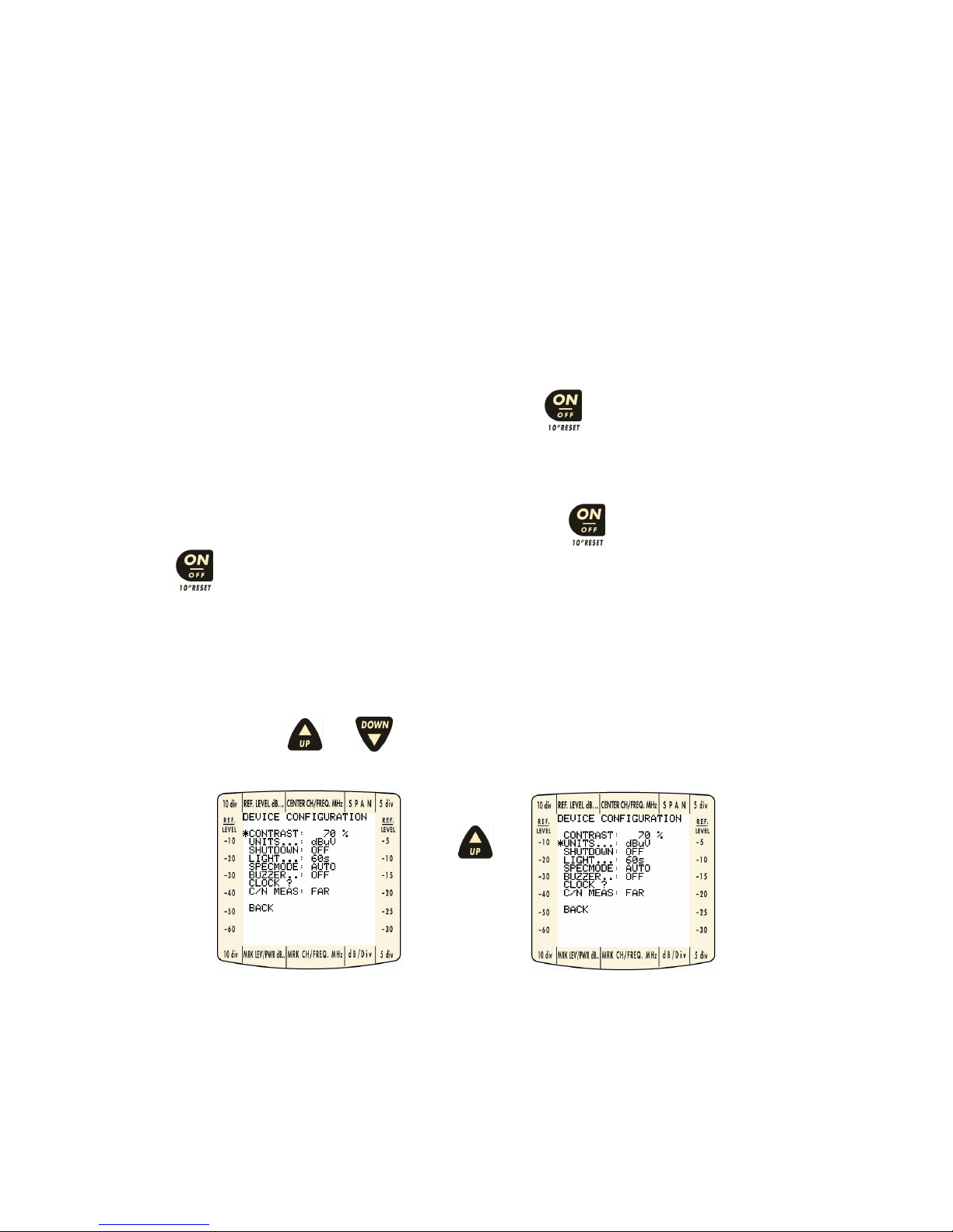
On menu screens, using and keys move the selector tool (*) from one item to the next.
Figure 1: Text Screen Navigation Example.
Page 8
Omnia-6 User’s Guide Draft Version
8
For graphic screens, the , and keys move the selector tool (*) clockwise and anti-clockwise,
respectively, to items with more than one user selection. Note that the selector tool rotation is relative to its
original starting position and may sometimes appear to move in the wrong direction.
Figure 2: Graphic Screen Navigation.
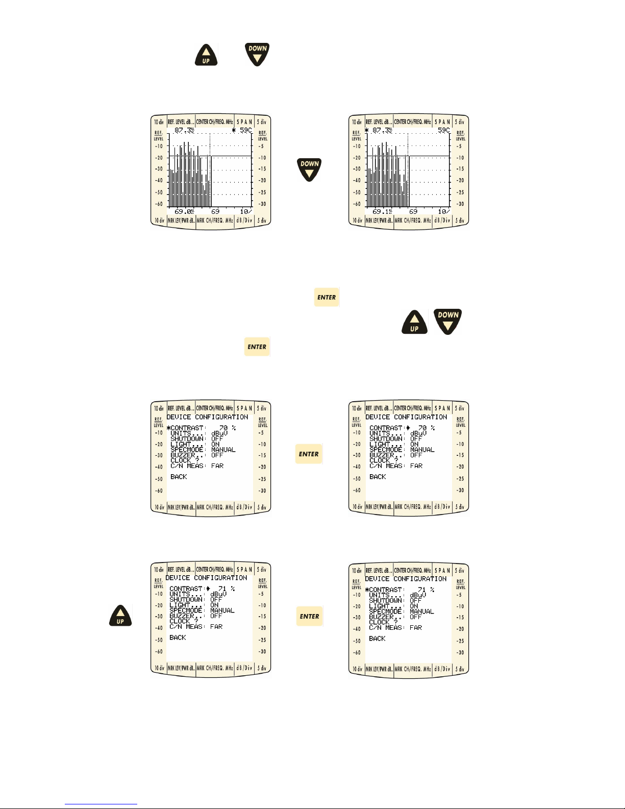
With the selector tool (*) beside it, the user can press
and update the values on the selected item. A
solid arrow will appear beside the current value. Pressing the arrow keys (
, ) will then allow the
user to change the value. Pressing
again will keep the current value and deactivate the ability to
update the item. The solid arrow indicator is replaced by the selector tool (*).
Figure 3: Text Enter Key Use.
Page 9
Omnia-6 User’s Guide Draft Version
9
Figure 4: Graphic Enter Key Use.
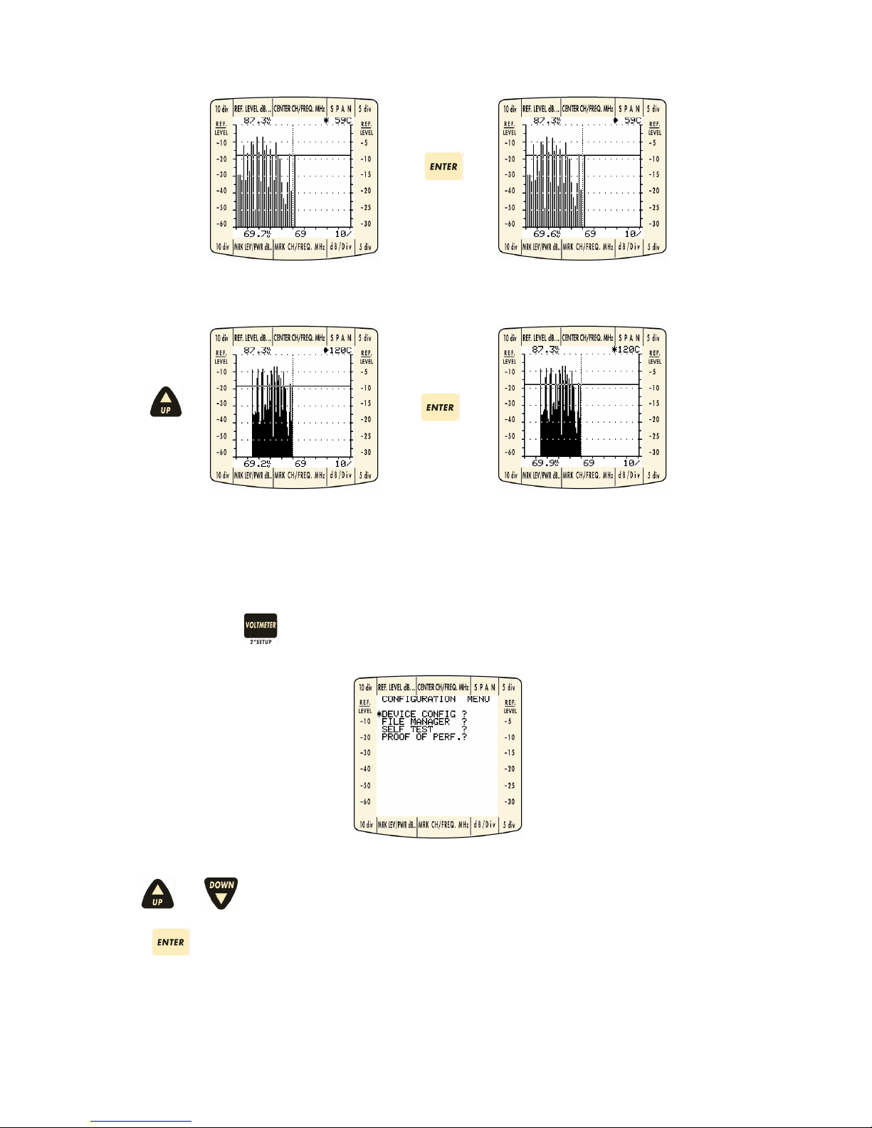
3.0 INSTRUMENT SETUP
Pressing and holding for 2 seconds takes you to the configuration menu:
Use
and keys to select the function required.
Press
to choose the selection.
Page 10
Omnia-6 User’s Guide Draft Version
10
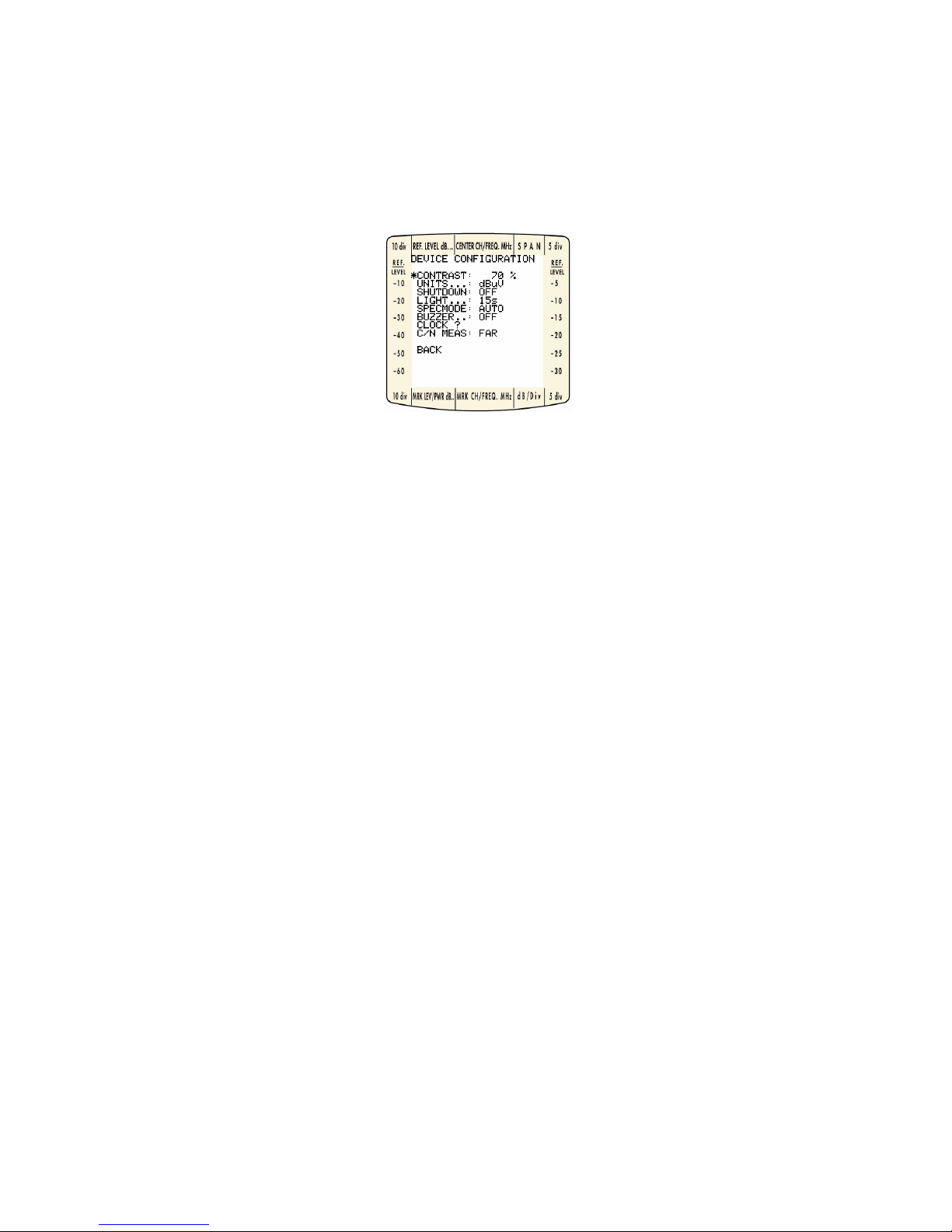
4.0 DEVICE CONFIGURATION
Before using your OMNIA-6 for the first time, the unit needs to be configured to the settings required for your
cable system. The unit also has some one-time configurations that need to be set. Turn the unit on and then
press the Special Key for two seconds. The Configuration menu appears as shown below (NOTE: your
configuration may not agree with the factory settings shown here if the instrument has been previously
configured). Use the navigation methods described above to update items.
Figure 5: Configuration Menu.
4.1 Contrast
This adjusts the display contrast lighter and darker based on a 100% scale with a higher number indicating a
darker contrast.
4.2 Units
Units of measurement offer dBµV or dBmV options.
4.3 Shutdown
This sets the automatic shut down time. Two options are available: Off (the instrument only turns off
manually) or 5 minutes (the instrument turns off automatically when no key is pressed for the stated time)
4.4 Light
This function allows you to select the time duration of the back-light display start-up. Select either the backlight remaining always on, or it turning off after 15, 30, 45 or 60 seconds without use.
4.5 Specmode
This function allows you to select either automatic or manual spectrum mode.
4.6 Buzzer
This function allows you to activate an acoustic signal which helps you carry out the installation.
4.7 C/N Meas
This function allows you to select the C/N measurement and choose whether to carry it out NEAR or FAR.
Page 11
Omnia-6 User’s Guide Draft Version
11
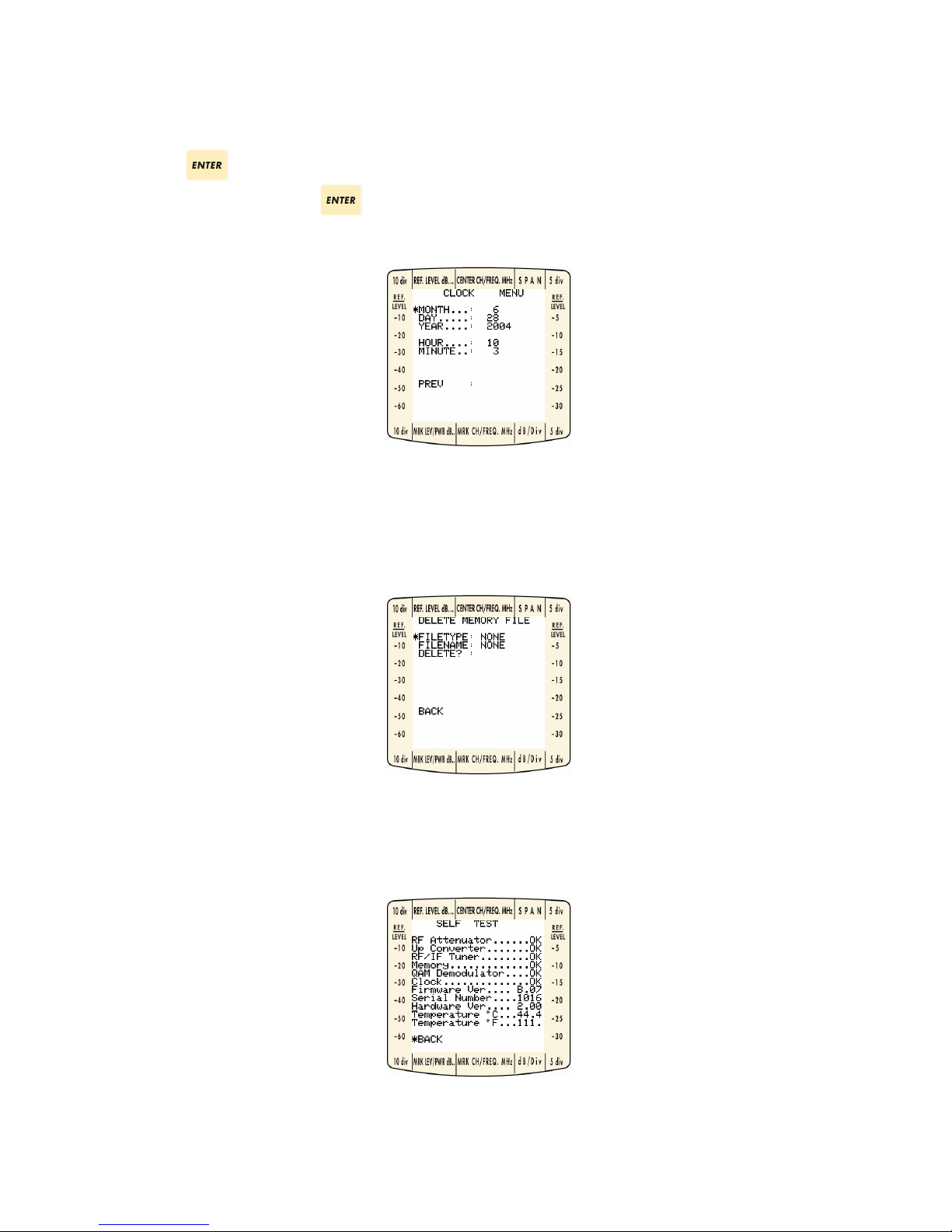
4.8 Clock?
In this Menu you can define the clock’s values and the date.
Pressing
on this item will take the user to the following menu. Enter the appropriate date and time.
Selecting PREV and pressing
allows you to return to the Device Configuration Menu.
Figure 6: Clock Menu.
4.9 File Manager
This area is used to delete storage files created by the user. Files that can be deleted are:
Custom Plans – The first plan in the system may not be deleted, but can be edited using internal functions.
4.10 Self Test
This function allows you to carry out a “health check” on the parts which make up the Omnia-6. Press any
key to quit the diagnostic test display. This also allows the visualization of the instrument’s Hardware and
Firmware versions.
Page 12
Omnia-6 User’s Guide Draft Version
12
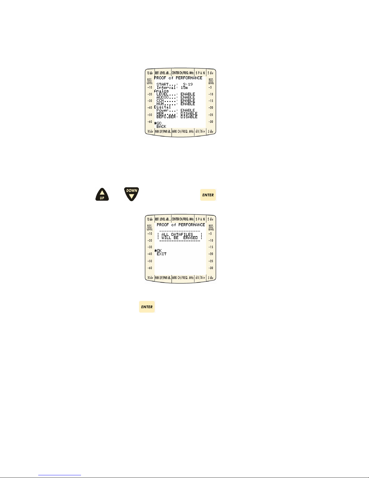
4.11 Proof of Performance
This function allows you to activate the instrument, at a specific time, to carry out measurements in CATV
installations.
START: Set the start time
Intervall: Set the measurement interval (from 15 minutes to 8 hours)
Analog: All the measurements are activated
Digital: It is possible to activate or deactivate the MER or bBER measurements
Navigate using the and keys on GO and press to confirm.
Confirm the OK selection using the key.
WARNING: when you confirm, all the other previously saved Loggers will be cancelled so that the numbering
of the new loggers starts from 1.
N.B.
- Before setting the instrument’s turn on START time you must set the instrument’s clock (see paragraph
3.0 and 4.8)
- If you confirm the selection, all the previously saved loggers will be cancelled.
- During this function the instrument must be connected to the mains power supply.
- To interrupt the measurement during scanning, simply press another key. To deactivate the
measurement when the instrument is already in Standby, simply turn in on using the ON key.
Page 13
Omnia-6 User’s Guide Draft Version
13
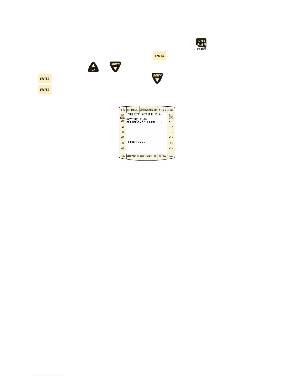
5.0 SELECTING ACTIVE PLAN
Before using the OMNIA-6, an ACTIVE PLAN must be selected. Pressing the key gives you a choice
between active plans that exist in the system. Press the
key when the desired ACTIVE PLAN name
is selected (*). Use the
and keys to select the proper plan for the given cable system. Press
again to choose the selection. Finally, use the key to select the CONFIRM item and press
to activate the selected plan name.
Figure 7: Active Plan Display.
Page 14
Omnia-6 User’s Guide Draft Version
14
6.0 MODES OF OPERATION
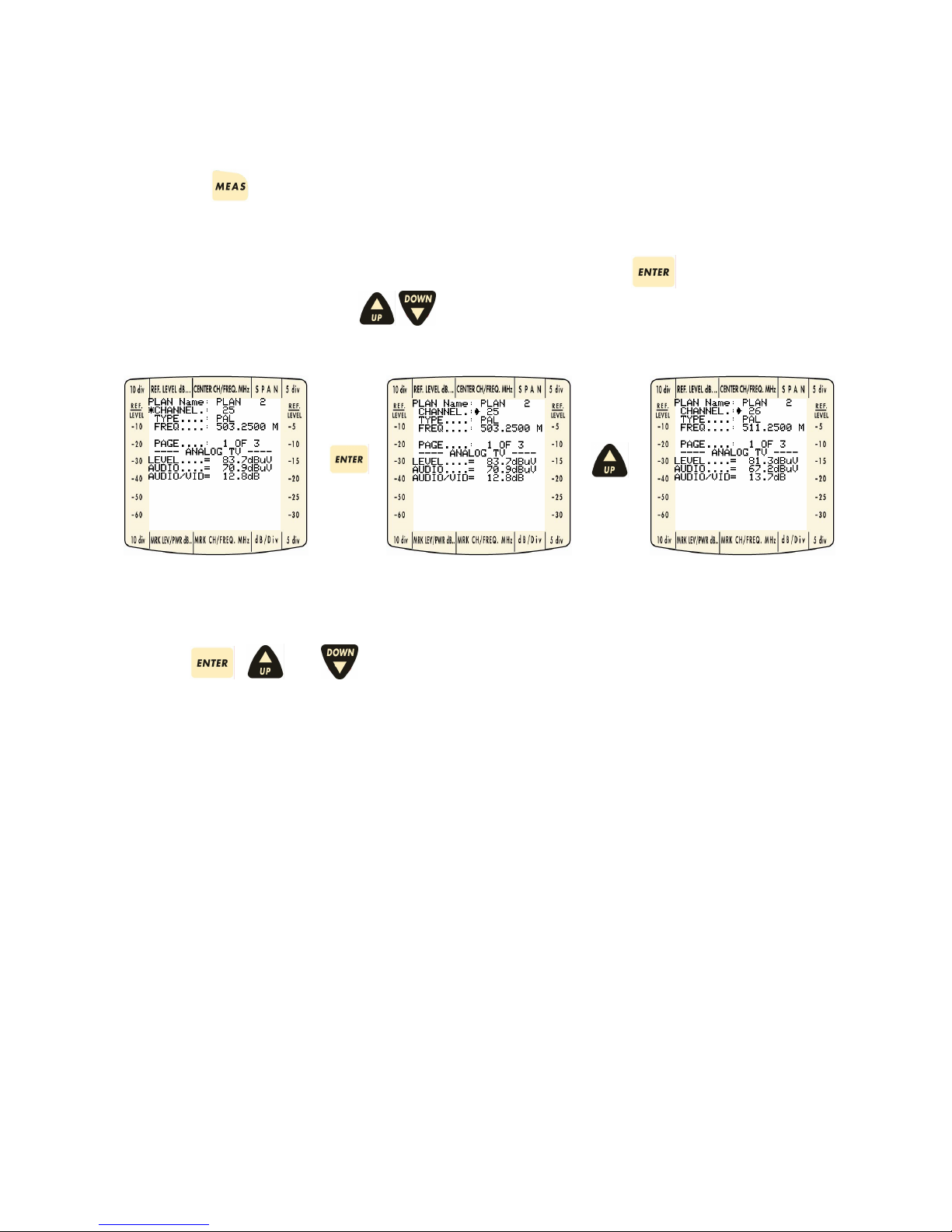
6.1 Measure Mode
Pressing the key displays detailed measurements for an individual channel. For analogue channels,
measurements displayed are Video Level, Audio Level, Video-Audio, CCN, and Hum. For digital channels,
multiplex power, MER, Before BER, After BER, Error Count, and Total Errors and peak/Val (ley)
measurements are available.
Navigation through different channels can be accomplished by pressing the
key when the selector
tool (*) is on the Channel. Using the
keys will cycle all available channels in the Plan.
Figure 8: Channel Selection.
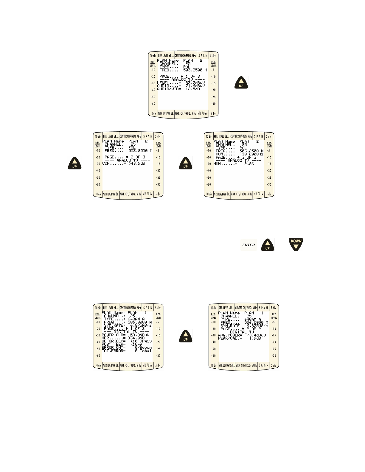
Using the
, , and keys with the Page item selected, allows you to navigate in the different
pages available for each channel. There are three pages available for PAL channels, two pages available
for QAM and VSB channels, and one page for DATA, CW, QPSK, FM and SCRAMB channels
.
Page 15
Omnia-6 User’s Guide Draft Version
15
7.0 ANALOG CHANNELS (PAL)
Figure 9: Analogue Measure Display Pages.
On the first page, the device gives real-time updates of the Visual Carrier Level, Audio Carrier Level, and the
Visual – Audio difference. The second page performs a Carrier to Composite Noise measurement at the
indicated channel. The third page performs a Hum measurement. Using the
, , and keys,
navigate to the HUM item and select from the available measurement options (50 Hz, 60 Hz, 100 Hz, 120
Hz, 10-2000 Hz).
8.0 QAM CHANNELS
Figure 10: QAM Measurement Display Pages.
The Power Old is the last power measurement made on the channel before carrying out MER, Before BER
and Post BER calculations. Going to Page 2 using standard navigation, provides
a real-time update of the
average channel power. Peak/VAL(ley) indicates in-band flatness within the indicated digital channel.
Page 16
Omnia-6 User’s Guide Draft Version
16
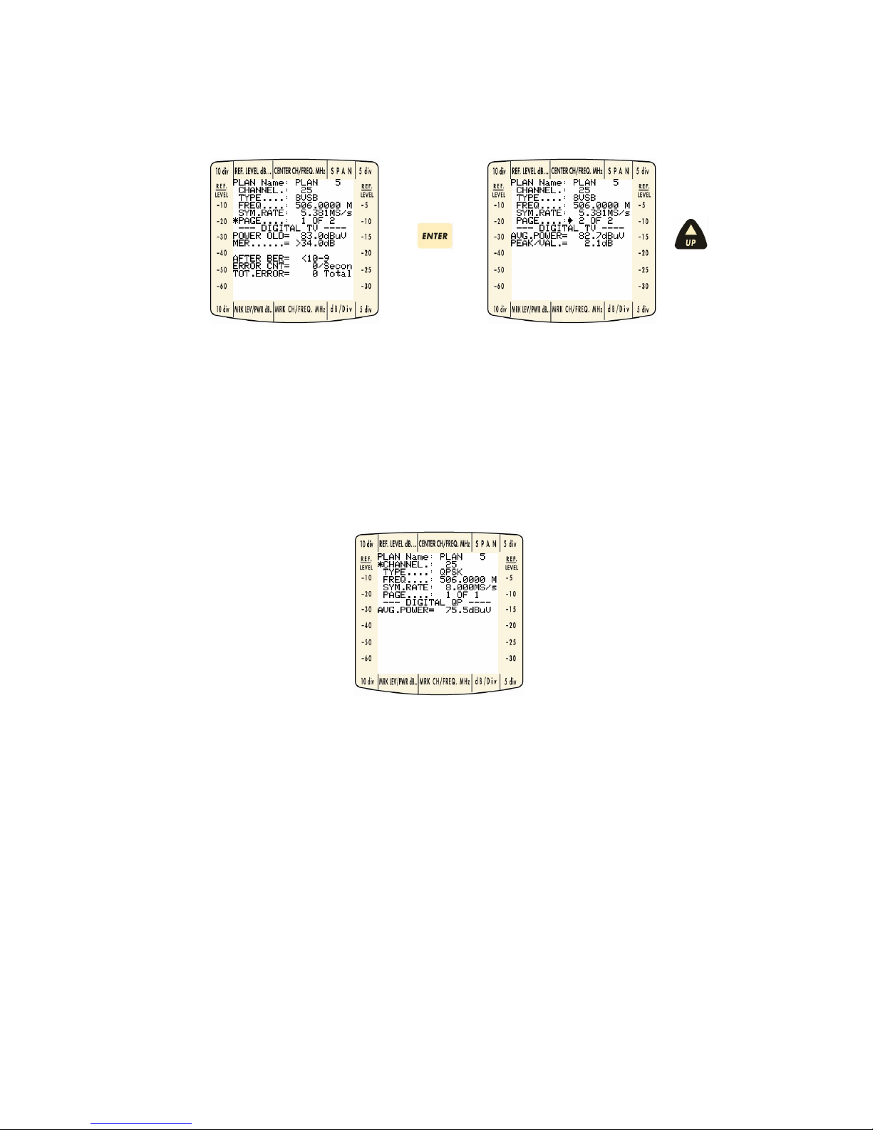
9.0 VSB CHANNELS
Power Old is the last power measurement carried out on the channel before MER, After BER calculations.
Going to Page 2 using standard navigation, provides a real-time update of the average channel power.
Peak/VAL(ley) indicates in-band flatness within the indicated digital channel.
10.0 QPSK/DATA CHANNELS
The device gives real-time updates of the average power.
Page 17
Omnia-6 User’s Guide Draft Version
17
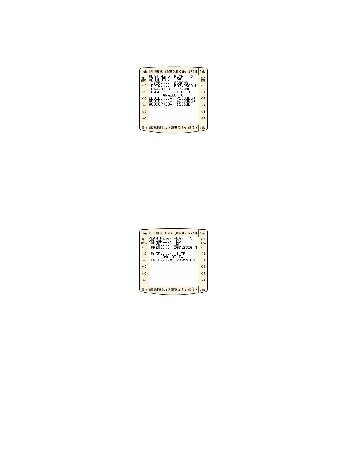
11.0 SCRAMB CHANNELS
The device gives real-time updates of the Video Carrier Level, Audio Carrier Level and the Video-Audio
difference.
12.0 FM/CW CHANNELS
The device gives real-time updates of the carrier level.
Page 18

Omnia-6 User’s Guide Draft Version
18
13.0 BARS MODE
Pressing the key takes you to the Sweep Display shown below. The centre of the graph is the current
marker channel.
Figure 11: Sweep Display.
Four on-screen measurement aids: frequencyspan, dB per division, channel, marker, and the reference
level selected and activated using normal navigation procedures, modify the data presentation. Choose the
one best suited for the current task.
13.1 Reference Level
The reference level is based on the signal levels present within the current bar parameters.
The reference level can be adjusted in 0,1 dB steps using the described navigation techniques.
13.2 Frequency Span
Span in Bars Mode adjusts the number of channels displayed on the sweep. Choices available are 9C, 19C,
29C, 59C, and 120C. Navigate to the SPAN item and use the
key to activate the item for adjustment.
Now, use the
, and keys to change the SPAN. Press again to lock the Span item at the
last chosen value.
Span
Marker Channel
dB/division
Reference Level
Marker Channel Level
Page 19

Omnia-6 User’s Guide Draft Version
19
13.3 dB/div
Four choices exist for changing the dB/div scaling: 1, 5, 10, and 20 dB/div. Use standard navigation to
select and adjust the dB/div as shown below. For convenience, level scales for the 10 dB/div and 5 dB/div
appear to the left and right of the display on the permanently attached bezel.
Figure 12: Changing dB per Division.
Page 20

Omnia-6 User’s Guide Draft Version
20
13.4 Channel Marker
You can display up-dated levels for any channel selected by the marker. Press at the Marker
Channel then use the
and keys to select a different channel as shown below. Press to
re-centre the display at the new marker channel.
Figure 13: Changing Marker Channel.
Page 21

Omnia-6 User’s Guide Draft Version
21
14.0 DISPLAYING AUDIO LEVEL
Audio Levels in the Bars Display integrate with the video level bars as hollow tic marks.
Press the
key to show all audio levels. Press the key again to remove them.
Figure 14: Displaying Audio Levels.
Page 22

Omnia-6 User’s Guide Draft Version
22
15.0 TILT MODE
Press the key to display the nine channels selected for the TILT (preferred channel) measurement.
You can modify the dB/div level and marker channel as described in BARS.
You can also display audio levels using the
and keys as described in BARS Mode.
You can also see the levels by pressing the TILT key. To remove them, simply press TILT again.
Figure 15: Tilt Mode Display.
Channels displayed for TILT can be easily changed by holding the key for 2 seconds, then using
standard navigation techniques described earlier in this document.
Figure 16: Tilt adjustment Display.
Page 23

Omnia-6 User’s Guide Draft Version
23
16.0 SPECTRUM MODE
Pressing provides a detailed snapshot of the cable system for the given frequency span. Reference
Level, Marker Channel, Frequency Span, dB/div, and Marker Frequency can be modified using the standard
navigation techniques. Use the
(anti-clockwise) and (clockwise) keys to cycle through items for
modification then press
to activate the selection option.
Figure 17: Spectrum Mode Display.
16.1 Span
Pressing when the selector tool (*) is at the SPAN item enables the use of the and keys
to select spans of 2 M(Hz), 5 M(Hz), 7 M(Hz), 10 M(Hz), 20 M(Hz), 50 M(Hz), 100 M(Hz), 200 M(Hz), 500
M(Hz), or FULL (870 MHz).
Span in MHz
Marker Channel
Reference Level
Marker Freq. Level
Marker Frequency
dB/division
Page 24

Omnia-6 User’s Guide Draft Version
24
16.2 dB/div
Four choices exist for changing the dB/div scaling: 1, 5, 10, and 20 dB/div. Use standard navigation to
select and adjust the dB/div. as shown below. For convenience, level scales for the 10 dB/div and 5 dB/div
appear to the left and right of the display on the permanently attached bezel.
Figure 18: Changing dB per Division.
16.3 Marker Frequency
Changing the marker frequency displays real-time levels for any frequency in the indicated SPAN. Pressing
will not re-centre the display to the marker frequency. Scrolling past the edges of the current graph is
prohibited
.
16.4 Reference Level
The reference level is based on the signal levels present within the current Spect parameters. The graph
reference level can be adjusted in 0.1 dB steps using the described navigation techniques
.
16.5 Marker Channel
Changing the marker channel recalculates the start and stop frequency thresholds with the newly selected
channel centred on the display. Levels currently displayed are defined by the marker channel along with the
marker frequency
.
Page 25

Omnia-6 User’s Guide Draft Version
25
17.0 CONSTELLATION MODE
Constellation mode can be activated whenever the marker channel type being displayed is digital (QAM or
VSB). Otherwise, this function is not active. The constellation display depends on the digital modulation (64QAM, 128-QAM, 256-QAM, 8 or 16 VSB). The instrument allows you to select which quadrant to display and
to ZOOM in to get a higher resolution image of the dot displacement at corner locations within the selected
quadrant.
Figure 19: Sample 64-QAM and 256-QAM displays.
Using standard navigation techniques, the user can change the zoom factor (ALL, 1/4, 1/8, 1/16) and
quadrant (I, II, III, IV) viewed. A 64-QAM signal sample is shown below…
…For ZOOMing,
Figure 20: Selecting Zoom.
Page 26

Omnia-6 User’s Guide Draft Version
26
…For changing Quadrant,
Figure 21: Selecting Quadrant.
Page 27

Omnia-6 User’s Guide Draft Version
27
18.0 INGRESS MODE
Pressing provides real-time display of the sweep spectrum from 5-65 MHz. A peak hold provides
temporal information about peaks detected in a particular location. The user can set the START and STOP
FREQUENCIES, the REFERENCE LEVEL, the SWEEP TIME, and the dB/div.
Figure 22: Ingress Mode Display.
Sweep Time
Reference Level
Marker Freq. Level
Marker Frequency
dB/division
Page 28

Omnia-6 User’s Guide Draft Version
28
19.0 START AND STOP FREQUENCIES
You can change the START and STOP frequencies of the Ingress display.
Press the
key and set START FR.
To set STOP FR. Press
19.1 Reference Level
The REFERENCE LEVEL is initially based on the signal levels present within the current Ingress frequency
boundaries. The user can adjust the graphic reference level in 0.1 dB steps using the described navigation
techniques.
19.2 Sweep Time
The Ingress SWEEP TIME defines the length of one START frequency to STOP frequency update. The
SWEEP TIME selection determines the dwell time at each frequency step. Standard navigation techniques
allow value selection. 50 ms0.1s, 0.3s, 0.5s, 1s, 2s, 5s, 10s, 20s, 50s
19.3 dB/div
Four choices exist for changing the dB/div scaling: 1, 5, 10, and 20 dB/div. Use standard navigation to
select and adjust the dB/div. as shown below. For convenience, level scales for the 10 dB/div and 5 dB/div
appear to the left and right of the display on the permanently attached bezel.
Figure 23: Changing dB per Division.
Page 29

Omnia-6 User’s Guide Draft Version
29
20.0 LEAKAGE MEASUREMENT
If you press the key you reach the Leakage menu for the measurement of losses in coaxial cables. It
is possible to set the working frequency.
20.1 Leakage Setup
Keep the key pressed for two seconds to reach the “Leakage Setup” menu, where it is possible to
select the antenna type, the antenna factor, the signal distance and minimum threshold.
Page 30

Omnia-6 User’s Guide Draft Version
30
21.0 STORING DATA
The OMNIA-6 provides storage for four data types: Measure (Data Logger), Ingress data, Spectrum data and
leakage data. When active, data may be STORed and RECALLed from each mode.
21.1 Storing Measurement data (Logger)
When the device is in Measurement Mode, press to cause the device to display the STORE LOGGER
MENU (figure below) . The user has the option of enabling or disabling the MER/BER measurements only.
All other measurements default to ENABLE and may not be changed.
Figure 24: Store Bin Menu.
Before storing a logger, choose which Bin will hold the data. There are 255 possible Loggers with actual
availability dependent upon the amount of remaining memory. An available memory readout appears at the
bottom of the screen display.
CAUTION: If a data LOGGER already exists on the system
and the LOGGER number is again user defined,
the original data will be overwritten without warning.
Press at the LoggerName selector tool (*), then use the and keys to select a Logger.
Press
when a logger has been chosen. If MER and BER measurement data is desired, simply move
the selector tool (*) to the appropriate item and press
, , and to enable or disable the
option.
With the storage LOGGER set up, move the selector tool (*) to the STORE item and press
. The
screen should indicate scan initiation as shown below.
Figure 25: Storing Data to a LOGGER File.
Page 31

Omnia-6 User’s Guide Draft Version
31
21.2 Storing Spectrum Data
With the device in Spect Mode, press to save data to a selected file name. Use standard navigation to
select one of 10 available zoom storage file locations.
CAUTION: If a zoom file already exists, no warning will be given for overwriting, so take care in selecting a
zoom file.
Figure 26: Storing a Zoom Sweep.
Press after moving the selector tool (*) to SAVE, and the file will be stored. A snapshot of the store
will now be present. Press
again to return to a live zoom update.
Page 32

Omnia-6 User’s Guide Draft Version
32
21.3 Storing Ingress Data
When the device is in Ingress Mode, press to save to a file name. Use standard navigation to select
an ingress file for storage. There are 10 ingress files available.
CAUTION: If an ingress file already exists, no warning will be given for overwriting, so take care in selecting
an ingress file.
Press after moving the selector tool (*) to SAVE, and the file will be stored. A snapshot of the store
will now be present. Press
again to return to a live ingress update.
Page 33

Omnia-6 User’s Guide Draft Version
33
21.4 Storing Leakage Data
When the device is in Leakage mode, press to save to a file name. Use standard navigation to
select an ingress file for storage. There are 10 ingress files available
.
CAUTION: If an ingress file already exists, no warning will be given for overwriting, so take care in selecting
an ingress file.
Figure 27: Storing a Leakage File.
Press after moving the selector tool (*) to SAVE, and the file will be stored. A snapshot of the store
will now be present. Press
again to return to a live ingress update.
Page 34

Omnia-6 User’s Guide Draft Version
34
22.0 RECALLING DATA
As with store, you can recall a Bin file, Zoom file, or Ingress file while in the respective mode (Measure,
Zoom, Ingress).
22.1 Recalling Measurement Data (Logger)
While in Measurement Mode press
to access the Recall Logger Menu. Using standard navigation,
select the desired logger and move the selector tool (*) to the RECALL item. Now press
. Once you
select an appropriate Logger file, the device will direct you back to Measurement Mode to view all data.
Data such as MER/BER may not display if they were not enabled during the store function for the particular
Bin. Press
to return to live data.
Figure 28: Logger Recall Menu.
N.B. When you recall a Data Logger, it is possible, using the BARS or TILT keys, to see the bars or tilt
respectively, with all the information detected by the Data Logger.
Page 35

Omnia-6 User’s Guide Draft Version
35
22.2 Recalling Spectrum Data
While in Spectrum Mode, pressing displays Zoom files available for recall. Using standard
navigation, select the desired bin and move the selector tool (*) to the RECALL item. Now press
.
Once you select an appropriate Spectrum file, the device will produce a snapshot of the stored data. Press
to return to live data.
Figure 29: Recall Spectrum File.
22. 3 Recalling Ingress Data
While in Ingress Mode, pressing displays Ingress files available for recall. Using standard navigation,
select the desired ingress and move the selector tool (*) to the RECALL item. Now press
. Once you
select an appropriate Ingress file, the device will produce a snapshot of the stored data. Press
to
return to live data.
Figure 30: Recall Ingress File.
Page 36

Omnia-6 User’s Guide Draft Version
36
22.4 Recalling Leakage Data
While in Leakage Mode, pressing displays Ingress files available for recall. Using standard
navigation, select the desired ingress and move the selector tool (*) to the RECALL item. Now press
. Once you select an appropriate Ingress file, the device will produce a snapshot of the stored data.
Press
to return to live data.
Figure 31: Recall Leakage File.
Page 37

Omnia-6 User’s Guide Draft Version
37
23.0 SOUND MODE
When in any mode, press to hear the currently selected channel’s audio. Press again to listen
to the TV Sync.
Figure 32: Sound Carrier Display.
While in Sound Carrier Mode, press to activate the audio volume control. Use the
and keys to increase or lower the volume.
Figure 33: Loudness Display.
23.1 Radio
Press the key for two seconds to activate Radio mode.
If a radio channel is present in the chosen plan you can hear the selected channel.
Press “UP” or “DOWN” to select and hear a RADIO channel.
Page 38

Omnia-6 User’s Guide Draft Version
38
24.0 VOLTMETER MODE
The OMNIA-6 automatically senses line frequency AC as well as DC voltages that may be present at the test
point. With the instrument connected to the test point in question, press
to activate voltmeter mode.
The display shows the voltage type and the value in the appropriate readout area. The selector tool is not
active in this mode.
Figure 34: Voltmeter Display.
Page 39

Omnia-6 User’s Guide Draft Version
39
25.0 HOW TO MANUALLY CREATE A CUSTOM PLAN
25.1 How to copy Source Plan to Destination Plan
Press and hold the for 2 seconds until the SELECT FILE PLAN title is displayed. This screen allows
the user to copy a SOURCE plan to a DESTINation plan. The SOURCE plans available are a set of default
MASTER PLANS pre-loaded into the device (i.e. Euro/IND, UK/HK etc.) and any custom plans already
present in the device. The DESTINation custom plans are labelled at the factory as PLAN 1, 2, 3, 4, 5, and 6.
Press
Figure 35: Select Source Plan.
It is possible to insert the channel search mode by choosing either “MANUAL” or “AUTO”. In “MANUAL”
each channel is inserted manually, whereas in “AUTO” all the channels with a level above the set threshold
“THRESH” are inserted automatically.
Continue to press until the plan desired is present. Once a SOURCE plan selection has been made,
press
and press to go to the DESTINATion selection.
Page 40

Omnia-6 User’s Guide Draft Version
40
Now select the DESTINATION plan required as shown in the examples below.
Figure 36: Select Destination Plan.
Pressing when the selector is on CONFIRM? begins the copying process. A WAIT message will be
shown with a progress bar at the bottom of the screen. After the copy process is complete, the device will
display the Edit Channel Plan’s Menu. Note: You can modify an existing custom plan in the device by
copying the custom plan to itself. For example, choose Plan 2 in the SOURCE and Plan 2 in the
DESTINATION.
Page 41

Omnia-6 User’s Guide Draft Version
41
25.2 How to edit Channel Plan
The user can modify existing channels, delete, or adding channels manually. Use the standard navigation
techniques described in the Introduction to select channels, types, frequencies, symbol rates (for digital
channels), and level offset (for scrambled channels).
Figure 37: Edit Channel Plan Screen.
25.3 Modifying Channels
If the proper channel format is selected (Standard), very little modification is required to core analogue
channels included in the plan, except for additional offsets from standard or scrambled channels. The main
adjustment required to be made to the plan is to properly set any digital channels existing in the cable
system.
25.4 Selecting Channels
Use standard navigation to navigate to the channel required for modification as shown below.
Figure 38: Select Channel.
Continue pressing
until the desired channel is reached, then press to complete the channel
selection process. Step through available options described below to set channel parameters.
Page 42

Omnia-6 User’s Guide Draft Version
42
25.5 Selecting channel types
There are numerous channel types including different digital channel types for various regions of the world.
Using standard navigation, select the TYPE to change the channel. Typical types used are described below:
• SCRAMB – Analogue channels that are scrambled and need an associated level (dB) offset.
• NTSC – typical format for North American analogue TV channel
• PAL – typical format for European analogue TV channel
• QAM256B – J83 Annex B with 256 QAM modulation (typical North American)
• QAM128B – J83 Annex B with 128 QAM modulation (typical North American)
• QAM64B – J83 Annex B with 64 QAM modulation (typical North American)
• QAM32B – J83 Annex B with 32 QAM modulation (typical North American)
• QAM16B – J83 Annex B with 16 QAM modulation (typical North American
• QAM256A – J83 Annex A with 256 QAM modulation (typical European)
• QAM128A – J83 Annex A with 128 QAM modulation (typical European)
• QAM64A – J83 Annex A with 64 QAM modulation (typical European)
• QAM32A – J83 Annex A with 32 QAM modulation (typical European)
• QAM16A – J83 Annex A with 16 QAM modulation (typical European)
• QAM256C – J83 Annex C with 256 QAM modulation
• QAM128C – J83 Annex C with 128 QAM modulation
• QAM64C – J83 Annex C with 64 QAM modulation
• QAM32C – J83 Annex C with 32 QAM modulation
• QAM16C – J83 Annex C with 16 QAM modulation
• 8VSB
• 16VSB
• QPSK
• DATA
• DISABLE
• CW
• FM
Figure 39: Select Channel Type.
Page 43

Omnia-6 User’s Guide Draft Version
43
25.6 Selecting frequencies
Use standard navigation to select the FREQ item on the screen. Press and hold
or to quickly
change to the frequency required. As you get closer to the required frequency, press the individual keys one
at a time to better control the frequency update. If the correct frequency for a video carrier or the centre
frequency for a digital carrier is not correct, the measurements made by the unit may be incorrect or function
improperly.
Figure 40: Select Frequency.
25.7 Symbol Rate
When a digital type is selected (e.g. QAM256B, QAM64B), the symbol rate item appears on the screen. Use
standard navigation to select the Symbol Rate and modify using
or . The correct symbol rate
must be entered in order for the digital measurements to function correctly. Typical symbol rates for a
QAM64B and QAM256B are 5.056 MS/sec and 5.361 MS/sec respectively.
Figure 41: Select Symbol Rate.
Page 44

Omnia-6 User’s Guide Draft Version
44
25.8 Level Offset
When a channel is set as type SCRAMB, the Offset item appears on the screen. This offset will be applied
to each video carrier measurement made on the channel. Use standard navigation to select the Offset item
and adjust accordingly using
or . Options range from –10.0 to 10.0 dB.
Figure 42: Select Level Offset.
Once you have finished setting the options (type, frequency, symbol rate, offset) described below, navigate
the selector tool (*) to REPLACE and press
.
Figure 43: Replace Channel.
Page 45

Omnia-6 User’s Guide Draft Version
45
25.9 Deleting Channels
Using standard navigation, select the channel you want to delete. Move the selector tool(*) down to the
DELETE item. Press
. A WAIT message will appear, then the channel will no longer be on the list.
If you are deleting a block of channels, start with the channel with the highest frequency first to facilitate the
deleting process.
Figure 44: Delete Channel.
25.10 Adding Channels
You can only add a channel in the custom plan if the 6 MHz slot that the channel would fall in does not have
an allocation in the current plan. For example, you have channels 79 and 81 allocated, but channel 80 is not
defined. If that is the case, using standard navigation, change the channel to the adjacent channel below or
above the channel to be added. Now change the frequency to the desired frequency using
or .
As the frequency moves into the empty 6 MHz slot, the REPLACE and DELETE items will disappear and the
ADD will appear. A channel name will automatically be assigned depending on the type of channel (starts at
C 1 for analogue, Q1 for QAM channel, D 1 for any data channels, and FM 1 for an FM channel). This
channel name can not be altered. Once all the channel parameters have been set, move the selector tool (*)
to the ADD item and press
.
Figure 45: Adding Channels.
Page 46

Omnia-6 User’s Guide Draft Version
46
25.11 Print
Press the
key to reach the print menu, where it is possible to choose the type of program required
(LIVE/STORED) and the PLANName. To print select and press
.
To print the screen display, press the
key for two seconds.
Page 47

Omnia-6 User’s Guide Draft Version
47
SERVICE NOTES & GUARANTEE REGULATIONS
1) Rover Laboratories. S.p.A. guarantees the repair of its manufactured equipment for a period of 24
months.
2) IMPORTANT: the guarantee becomes valid when Rover Laboratories S.p.A. receives the correctly
compiled warranty coupon, or alternatively, on presentation of an invoice or receipt, clearly showing the
date of purchase.
3) The guarantee covers the replacement, free of charge, of all parts which are not functioning correctly
due to manufacturing faults.
4) The guarantee is considered void if:
a. the equipment is tampered with or repaired by non-authorized personnel;
b. damage is found, caused by the incorrect use of the equipment, without following the advice
explained in the User’s Guide accompanying the equipment;
c. damage is found caused by the use of the equipment in unsuitable working environments.
5) The following parts are not covered by the guarantee:
a. Parts subject to wear, such as aesthetics ones;
b. Batteries.
6) The equipment can only be repaired by the manufacturer or by an authorised Rover Laboratories service
centre.
a. Before returning the meter for repair, always contact Rover Laboratories S.p.A. or an authorised
service centre to obtain the return procedure for your analyzer.
b. When returning the meter, always send it with the following documentation attached: the fully-
compiled FAULT IDENTIFICATION FORM, a transport document and the eventual request for an
estimate of repair costs.
c. Please note that the request for an estimate of repair costs must be submitted upon return of the
analyser with a written note. If the repair cost estimate is not accepted, Rover Laboratories reserves
the right to charge the customer for the estimate analysis costs.
7) Risks and costs for transport to Rover Laboratories S.p.A. must be sustained by the buyer. After repair,
if the equipment is under guarantee, Rover Laboratories S.p.A. will pay for the transport returning the
goods to the customer. If the instrument is not under guarantee, after repair, the equipment will be
returned by courier service with the amount to be paid by the customer shown in the invoice.
8) The equipment can not be replaced and the guarantee extended after the repair of a fault.
9) The guarantee does not cover compensation for direct or indirect damages of any kind to people or
goods caused by the use of the equipment and/or compensation caused by the suspension of use due to
eventual repairs.
10) Rover Laboratories. S.p.A. is not responsible for eventual tampering and/or modifications that may cause
the goods to no longer adhere to the European “CE” regulations, especially regarding EMC and safety.
Page 48

Omnia-6 User’s Guide Draft Version
48
N
N
O
O
T
T
E
E
S
S
Page 49

Omnia-6 User’s Guide Draft Version
49
“OMNIA-6” FRONT PANEL DESCRIPTION
1. RF input connector, 75 ohm
(easily interchangeable “F” or “IEC”)
2. Model and frequency description
3. RS 232 socket
4. Instrument model
5. Liquid Crystal Display
6. ABS shook-proof and rain-proof housing
7. Keys to activate the various menus on the Display
8. INGRESS measurement activation key
9. UP arrow key
10. LEAKAGE measurement activation key
11. Chs Plan key
12. DOWN arrow key
13. SAVE key
14. PRINT key
15. RECALL key
16. Voltmeter activation key
17. Power ON/OFF key
18. Mains AC LED (mains connection)
19. Meas key
20. Constellation function
21. ENTER key
22. BARS function key
23. TILT measurement key
24. SPECTRUM key
25. TV SYNC. & audio LED
26. Audio selection key
27. Volume adjustment key
28. Fast battery charge monitoring LED
29. Connector for external power supply and/or battery charge.
Page 50

Omnia-6 User’s Guide Draft Version
50
“OMNIA-6” FRONT PANEL
Page 51

Omnia-6 User’s Guide Draft Version
51
Page 52

Omnia-6 User’s Guide Draft Version
52
Page 53

Page 54

Omnia-6 User’s Guide Draft Version
54
Page 55

N
N
O
O
T
T
E
E
S
S
Page 56

Omnia-6 User’s Guide Draft Version
56
 Loading...