


E-M-HW4v2-Main_13 |
Rotronic AG |
|
Bassersdorf, Switzerland |
||
|
||
Document code |
Unit |
|
|
|
|
HW4 software v.2 General instructions and functions |
Instruction Manual |
|
common to all devices |
Document Type |
|
|
||
|
|
|
Document title |
Page 1 of 165 |
|
|
||
|
|
HW4 Software version 2
General instructions and functions common to all devices
© 2008; Rotronic AG |
E-M-HW4v2-Main_13 |

|
|
Rotronic AG |
E-M-HW4v2-Main_13 |
|
|
|
|
Bassersdorf, Switzerland |
Document code |
Unit |
|
HW4 software v.2 General instructions and functions |
Instruction Manual |
|
common to all devices |
|
|
|
|
Document Type |
|
|
Page 2 of 165 |
Document title |
|
|
Table of contents |
|
|
1 |
ORGANIZATION OF THE HW4 MANUALS ........................................................................ |
5 |
2 |
OVERVIEW ........................................................................................................................... |
6 |
2.1 |
HW4 Standard Edition ................................................................................................................. |
6 |
2.2 |
HW4 Professional Edition ............................................................................................................ |
6 |
2.3 |
HW4 Lite ...................................................................................................................................... |
7 |
2.4 |
HW4 Professional with OPC Server............................................................................................. |
7 |
2.5 |
HW4 Professional with AwQuick.................................................................................................. |
7 |
2.6 |
HW4 Professional Trial Version ................................................................................................... |
7 |
2.7 |
HW4 Validated ............................................................................................................................. |
7 |
3 |
NEW IN VERSION 2.1.0 OR HIGHER ................................................................................. |
8 |
3.1 |
HW4 v 2.1.0 ................................................................................................................................. |
8 |
3.2 |
HW4 v 2.1.1 ................................................................................................................................. |
9 |
3.3 |
HW4 v 2.2.0 ................................................................................................................................. |
9 |
3.4 |
HW4 v 2.3.0 ................................................................................................................................ |
10 |
4 |
INSTALLATION .................................................................................................................. |
12 |
4.1 |
Software Licensing Agreement ................................................................................................... |
12 |
4.2 |
HW4 requirements ...................................................................................................................... |
12 |
4.3 |
Installing HW4............................................................................................................................. |
14 |
4.4 |
Updating HW4 to a newer version .............................................................................................. |
18 |
4.5 |
Uninstalling HW4 (full uninstall) .................................................................................................. |
18 |
5 |
CONNECTING DEVICES TO THE HW4 PC...................................................................... |
19 |
5.1 |
Definition: masters and slaves (HW4 Professional) .................................................................... |
19 |
5.2 |
Connection methods for master devices ..................................................................................... |
19 |
5.3 |
Devices used as RS-485 slaves (HW4 Professional) ................................................................. |
19 |
6 |
PREPARING FOR DEVICE CONNECTION ...................................................................... |
21 |
6.1 |
Physical serial port...................................................................................................................... |
21 |
6.2 |
Bluetooth virtual serial port ......................................................................................................... |
21 |
6.3 |
USB port ..................................................................................................................................... |
21 |
6.4 |
Ethernet (TCP/IP) connection ..................................................................................................... |
24 |
6.5 |
RS-485 slaves: address and Baud rate requirements................................................................. |
29 |
7 |
INITIAL START-UP ............................................................................................................ |
31 |
7.1 |
Language selection..................................................................................................................... |
31 |
7.2 |
Product key and registration ....................................................................................................... |
32 |
7.3 |
Automatic device discovery during initial start-up ....................................................................... |
34 |
7.4 |
Creating the first user (HW4 Professional).................................................................................. |
35 |
7.5 |
Access to functions and screens (HW4 Professional)................................................................. |
35 |
8 |
SEARCHING FOR DEVICES WITH HW4.......................................................................... |
36 |
8.1 |
Searching for master devices...................................................................................................... |
36 |
8.2 |
Searching for RS-485 slaves (HW4 Professional) ...................................................................... |
36 |
9 |
HW4 MAIN SCREEN .......................................................................................................... |
37 |
9.1 |
Device Tree (left pane) ............................................................................................................... |
38 |
9.2 |
Right pane in Device View mode ................................................................................................ |
41 |
9.3 |
Right pane in Group View mode ................................................................................................. |
49 |
10 HW4 MAIN MENU BAR...................................................................................................... |
53 |
|
10.1 |
File .............................................................................................................................................. |
53 |
10.2 |
Devices and Groups ................................................................................................................... |
54 |
© 2008; Rotronic AG |
E-M-HW4v2-Main_13 |
E-M-HW4v2-Main_13 |
Rotronic AG |
|
|||
Bassersdorf, Switzerland |
|||||
|
|
|
|||
Document code |
Unit |
|
|||
|
|
|
|||
HW4 software v.2 General instructions and functions |
|
Instruction Manual |
|||
common to all devices |
|
Document Type |
|||
|
|
|
|
||
|
|
|
|
|
|
Document title |
Page |
3 of 165 |
|||
|
|
||||
|
|
|
|
||
10.3 |
View ............................................................................................................................................ |
|
58 |
||
10.4 |
Settings and Tools ...................................................................................................................... |
|
59 |
||
10.5 |
Help ............................................................................................................................................ |
|
60 |
||
10.6 |
Shortcut buttons.......................................................................................................................... |
|
60 |
||
11 |
|
ETHERNET CONFIGURATION TOOL .............................................................................. |
|
61 |
|
12 |
USERS AND PASSWORDS (HW4 Professional) ............................................................ |
|
62 |
||
12.1 |
Minimum user rights.................................................................................................................... |
|
62 |
||
12.2 |
Additional user rights .................................................................................................................. |
|
63 |
||
12.3 |
Creating and logging-on the first user ......................................................................................... |
|
64 |
||
12.4 |
User table form ........................................................................................................................... |
|
67 |
||
12.5 |
Menu bar..................................................................................................................................... |
|
67 |
||
12.6 |
User login security ...................................................................................................................... |
|
69 |
||
13 |
|
COLUMN HEADERS .......................................................................................................... |
|
69 |
|
14 |
|
HW4 GLOBAL SETTINGS ................................................................................................. |
|
72 |
|
14.1 |
View Tab ..................................................................................................................................... |
|
72 |
||
14.2 |
General Tab ................................................................................................................................ |
|
74 |
||
14.3 |
Language/Unit System Tab ........................................................................................................ |
|
77 |
||
14.4 |
File Locations Tab....................................................................................................................... |
|
79 |
||
14.5 |
Graph Settings Tab..................................................................................................................... |
|
81 |
||
14.6 |
Alarm Settings Tab (HW4 Professional) ..................................................................................... |
|
84 |
||
14.7 |
Events Tab (HW4 Professional).................................................................................................. |
|
86 |
||
15 |
USER EVENTS (HW4 Professional)................................................................................. |
|
87 |
||
15.1 |
Menu bar..................................................................................................................................... |
|
88 |
||
16 |
ALARM TABLE (HW4 Professional) ................................................................................ |
|
89 |
||
16.1 |
Alarm acknowledgement............................................................................................................. |
|
90 |
||
16.2 |
Alarm table menu bar and buttons .............................................................................................. |
|
91 |
||
17 |
|
PSYCHROMETRIC CONVERSIONS ................................................................................. |
|
93 |
|
18 |
|
DEVICE PROTECTION ...................................................................................................... |
|
94 |
|
19 |
DATA LOGGING - directly on the PC .............................................................................. |
|
96 |
||
19.1 |
Start logging data to the PC ........................................................................................................ |
|
96 |
||
19.2 |
Stop logging data to the PC ........................................................................................................ |
|
98 |
||
20 |
ACCESSING LOG FILES, PROTOCOLS AND EVENT FILES......................................... |
99 |
|||
21 |
VIEW / SIGN A PROTOCOL ............................................................................................ |
|
101 |
||
21.1 |
Protocol viewer menu bar ......................................................................................................... |
|
103 |
||
22 |
VIEW / SIGN A LOG FILE ................................................................................................ |
|
104 |
||
22.1 |
Opening a log file in HW4 View Data ........................................................................................ |
|
104 |
||
22.2 |
View Data menu bar ................................................................................................................. |
|
108 |
||
22.3 |
View Data Toolbar .................................................................................................................... |
|
116 |
||
22.4 |
Graph Tab................................................................................................................................. |
|
117 |
||
22.5 |
Data Table / File Name Tab ...................................................................................................... |
|
121 |
||
22.6 |
Working with log files and graphs (How To).............................................................................. |
|
121 |
||
23 |
ALARM INDICATION & REPORTING - Overview.......................................................... |
|
122 |
||
23.1 |
Standard alarm notification (all HW4 versions) ......................................................................... |
|
122 |
||
23.2 |
Optional alarm notification (HW4 Professional)......................................................................... |
|
123 |
||
23.3 |
Alarm Reporting (HW4 Professional) ........................................................................................ |
|
124 |
||
23.4 |
Additional alarm data ................................................................................................................ |
|
124 |
||
© 2008; Rotronic AG |
E-M-HW4v2-Main_13 |
E-M-HW4v2-Main_13 |
|
Rotronic AG |
|
||
|
Bassersdorf, Switzerland |
||||
|
|
|
|
||
Document code |
|
Unit |
|
||
|
|
|
|
||
HW4 software v.2 General instructions and functions |
|
|
Instruction Manual |
||
common to all devices |
|
|
Document Type |
||
|
|
|
|
|
|
|
|
|
|
|
|
Document title |
|
Page |
4 of 165 |
||
|
|
|
|||
|
|
|
|
||
24 |
ERES REGULATORY COMPLIANCE (HW4 Professional)........................................... |
128 |
|||
24.1 |
Required settings and selections .............................................................................................. |
|
128 |
||
24.2 |
Electronic records ..................................................................................................................... |
|
128 |
||
24.3 |
Log File Format......................................................................................................................... |
|
128 |
||
25 |
RECORD KEEPING - Overview (HW4 Professional) |
.................................................... |
129 |
||
25.1 |
Event Files ................................................................................................................................ |
|
129 |
||
25.2 |
Protocols................................................................................................................................... |
|
133 |
||
25.3 |
Cross referencing protocols and event files .............................................................................. |
|
135 |
||
26 |
|
FILE PROTECTION.......................................................................................................... |
|
136 |
|
26.1 |
Authentication stamp ................................................................................................................ |
|
136 |
||
26.2 |
Overview................................................................................................................................... |
|
137 |
||
27 |
RELOCATING THE HW4 USER FOLDER ...................................................................... |
|
137 |
||
27.1 |
Method 1 (using Windows Explorer) ......................................................................................... |
|
138 |
||
27.2 |
Method 2 (after the initial HW4 start-up) ................................................................................... |
|
141 |
||
27.3 |
Retrieving your previous settings and other data ...................................................................... |
|
145 |
||
28 |
CHANGING THE BAUD RATE OF AN ETHERNET DEVICE ......................................... |
147 |
|||
29 |
CONCURRENT HW4 SESSIONS ON DIFFERENT WORKSTATIONS.......................... |
150 |
|||
29.1 |
Polling synchronization ............................................................................................................. |
|
151 |
||
30 |
MULIPLE HW4 SESSIONS ON THE SAME PC.............................................................. |
|
154 |
||
31 |
STARTING HW4 AUTOMATICALLY with Windows...................................................... |
|
154 |
||
32 |
|
BASIC ETHERNET CONCEPTS...................................................................................... |
|
156 |
|
32.1 |
Compatibility requirements ....................................................................................................... |
|
156 |
||
32.2 |
DHCP........................................................................................................................................ |
|
157 |
||
32.3 |
MAC Address............................................................................................................................ |
|
157 |
||
33 |
WATER ACTIVITY MEASUREMENT WITH HW4 ........................................................... |
|
157 |
||
33.1 |
Water Activity: definition and applications ................................................................................. |
|
157 |
||
33.2 |
Instruments and probes for measuring water activity................................................................ |
|
159 |
||
33.3 |
Water activity measurement modes in HW4 ............................................................................. |
|
159 |
||
33.4 |
Mode selection and settings ..................................................................................................... |
|
160 |
||
33.5 |
Using the AwE mode ................................................................................................................ |
|
161 |
||
33.6 |
Using the AwQuick mode.......................................................................................................... |
|
162 |
||
33.7 |
Water activity measurement report ........................................................................................... |
|
163 |
||
34 |
|
DOCUMENT RELEASES ................................................................................................. |
|
165 |
|
© 2008; Rotronic AG |
E-M-HW4v2-Main_13 |
E-M-HW4v2-Main_13 |
Rotronic AG |
|
Bassersdorf, Switzerland |
||
|
||
Document code |
Unit |
|
|
|
|
HW4 software v.2 General instructions and functions |
Instruction Manual |
|
common to all devices |
Document Type |
|
|
||
|
|
|
Document title |
Page 5 of 165 |
|
|
||
|
|
1 ORGANIZATION OF THE HW4 MANUALS
The HW4 manuals are organized in separate books so as to limit the size of the individual documents. A list of the HW4 manuals is provided in document E-M-HW4v2-DIR
|
HW4 Manuals |
|
Contents |
|
|
|
|||
|
|
|
General software description |
|
HW4 Main Book |
|
Installation, start-up and settings |
||
|
Device connection methods |
|||
|
|
|
||
|
|
|
Functions common to all devices used with HW4 |
|
|
|
|
|
|
|
|
|
Legacy devices (original HygroClip technology): |
|
|
|
|
o HygroLog NT data logger |
|
|
|
|
o HygroFlex 2, HygroFlex 3 and M3 transmitters (same |
|
|
|
|
|
icon in device tree) |
Device Specific Functions 1 |
|
o HygroLab 2 and HygroLab 3 bench indicators |
||
|
o |
HygroPalm 2 and HygroPalm 3 portable indicators |
||
(separate book for each device type or model) |
|
|||
|
o |
HygroClip DI digital interface |
||
|
|
|
||
|
|
|
o HygroClip Alarm programmable logic |
|
|
|
|
o |
HygroStat MB |
|
|
|
Device Manager (device configuration) and other device |
|
|
|
|
specific functions |
|
|
|
|
|
|
Probe Adjustment 1 |
|
Humidity and temperature adjustment function common to |
||
|
all legacy devices (original HygroClip technology) |
|||
|
|
|
||
|
|
|
|
|
|
|
|
Devices based on the AirChip 3000 technology such as: |
|
|
|
|
o HygroClip 2 (HC2) probes |
|
|
|
|
o HF3 transmitters and thermo-hygrostats |
|
|
|
|
o |
HF4 transmitters |
|
|
|
o |
HF5 transmitters |
Device Specific Functions 2 |
|
o |
HF6 transmitters |
|
|
o |
HF7 transmitters |
||
(separate book for each device type or model) |
|
|||
|
o |
HF8 transmitters |
||
|
|
|
||
|
|
|
o HL20 and HL21 data loggers |
|
|
|
|
o HP21, HP22 and HP23 hand-held indicators |
|
|
|
|
o Custom designed OEM products |
|
|
|
|
Device Manager (device configuration, AirChip 3000 |
|
|
|
|
functions) |
|
|
|
|
|
|
Probe Adjustment 2 |
|
Humidity and temperature adjustment function common to |
||
|
all devices based on the AirChip 3000 technology |
|||
|
|
|
||
|
|
|
|
|
Data Recording Function |
|
Data recording function common to all devices based on the |
||
|
AirChip 3000 technology |
|||
|
|
|
||
|
|
|
|
|
Both the HW4 manuals (software) and device specific manuals (hardware) are available on the HW4 CD. The manuals can also be downloaded from several of the ROTRONIC web sites.
© 2008; Rotronic AG |
E-M-HW4v2-Main_13 |
E-M-HW4v2-Main_13 |
Rotronic AG |
|
Bassersdorf, Switzerland |
||
|
||
Document code |
Unit |
|
|
|
|
HW4 software v.2 General instructions and functions |
Instruction Manual |
|
common to all devices |
Document Type |
|
|
||
|
|
|
Document title |
Page 6 of 165 |
|
|
||
|
|
2 OVERVIEW
The HW4 software was developed by ROTRONIC AG for use with the ROTRONIC line of digital instruments and devices. HW4 is available in the following versions:
2.1HW4 Standard Edition
o Unlimited number of instruments (depends on capabilities of PC and available ports)
o |
On-line display of the measured and calculated values (dew point or other), limited to one instrument at |
|
a time. |
o |
Automatic retention of the most recent data in a temporary on-line buffer (multiple instruments). |
o Logging of measured and calculated values to the PC (multiple instruments). o Easy-to-read graphs and data tables.
o Statistical data tools: mean, standard deviation, minimum and maximum of the recorded data (off line only).
o Data print-out (table or graph)
o Automatic device/instrument recognition and identification o Device/instrument configuration
o Access to the data recorded by a data logger and data transfer to the PC o Adjustment (calibration) of the HygroClip digital probes
o Psychrometric Conversion Tool
o Built-in security to protect against data manipulation
2.2HW4 Professional Edition
HW4 Professional edition complies with ERES regulations. This version of HW4 allows multiple users, with either administrator or standard rights and password protection.
o All the functionality of HW4 Standard Edition
o RS-485 multi-dropped sub-networks of up to 64 instruments per sub-network o On-line display of the data from multiple instruments and probes
o Possibility to overlay and synchronize data from several log files into a single graph o User Event Logging: automatically records user main operations.
o Multiple users distributed into two groups: administrator and standard, each with different rights o Self Event Logging: automatically records any software problem to facilitate troubleshooting
o Logger Event Logging: automatically records the data logger internal events and configuration changes.
oAutomatic creation of protocols detailing instrument configuration and programming changes as well as and probe adjustments.
o Optical or acoustical indication of an alarm condition, tracking of alarm conditions in a table, and possibility of printing a report, sending an e-mail, etc.
o Visual Indication an alarm conditions when viewing log file data o Password protected log-in
o Meets the requirements of FDA 21CFR Part II for electronic records and electronic signatures o Meets the EU GMP requirements regarding pharmaceuticals.
© 2008; Rotronic AG |
E-M-HW4v2-Main_13 |
E-M-HW4v2-Main_13 |
Rotronic AG |
|
Bassersdorf, Switzerland |
||
|
||
Document code |
Unit |
|
|
|
|
HW4 software v.2 General instructions and functions |
Instruction Manual |
|
common to all devices |
Document Type |
|
|
||
|
|
|
Document title |
Page 7 of 165 |
|
|
||
|
|
2.3HW4 Lite
HW4 Lite is a special version of HW4 Professional which includes all features of HW4 Professional while being restricted to devices of the HygroWin type.
2.4HW4 Professional with OPC Server
HW4 Professional with OPC server is a special version of HW4 Professional which includes all features of HW4 Professional while also providing OPC tags that can be enabled for each individual device communicating with HW4. This allows transferring data with practically any OPC client (requires configuration / programming of the OPC client by the user).
2.5HW4 Professional with AwQuick
HW4 Professional with AwQuick is a special version of HW4 Professional designed to facilitate measurement of the water activity (Aw) of foods, pharmaceuticals, etc. This version includes all the features of the regular HW4 Professional Edition. Two modes are available for measuring water activity: AwE and AwQuick. Both modes can be used with any of our instruments. In the AwE mode, HW4 monitors the natural equilibration of the product being measured and automatically stops the measurement process when equilibrium is reached. With most products, natural equilibrium requires from 45 to 90 minutes. The AwQuick mode reduces the time required to measure water activity to a few minutes, usually with almost the same accuracy as the AwE mode.
2.6HW4 Professional Trial Version
HW4 Trial is a fully functional version of HW4 Professional, including the OPC server and water activity measurement functionality. A compressed installation file (zip) can be downloaded free of charge from the ROTRONIC website at:
http://www.rotronic-humidity.com/software/humidity_software_download.php
Note: this web page is subject to change
Activation requires an HW4 product key which can be requested by filling a form on the ROTRONIC web site. A trial product key will be sent to your e-mail address. This must be entered in the registration form which appears when starting HW4 for the first time. After 30 days, the trial product key expires and HW4 can no longer be started.
2.7HW4 Validated
HW4 Validated offers the same functionality as HW4 Professional with OPC server. Additionally, the “HW4 e-compliance Package” is available. This extensive collection of documents (including template of qualification documents) is designed to support the “regulated user” by qualifying/validating HW4-based solutions.
© 2008; Rotronic AG |
E-M-HW4v2-Main_13 |
E-M-HW4v2-Main_13 |
Rotronic AG |
|
Bassersdorf, Switzerland |
||
|
||
Document code |
Unit |
|
|
|
|
HW4 software v.2 General instructions and functions |
Instruction Manual |
|
common to all devices |
Document Type |
|
|
||
|
|
|
Document title |
Page 8 of 165 |
|
|
||
|
|
3 NEW IN VERSION 2.1.0 OR HIGHER
3.1HW4 v 2.1.0
HW4 version 2.1.0 or higher includes all the functions and features of HW4 version 2.0.1 (last validated version) with the following modifications and additions:
● Organization of the HW4 manuals
Starting with HW4 version 2.1.0, the HW4 manuals are organized in separate books so as to limit the size of the individual documents:
● Alarm-Test scheduling
HW4 features a simulated alarm test that is used to automatically verify at regular intervals of time that the HW4 measurement system is currently operating and that an alarm notification will be issued whenever necessary.
Starting with version 2.1.0, HW4 adds the following options when scheduling the automatic simulated alarm test:
o Each hour
o Each 4 hours o Each 8 hours o Each 12 hours
The scheduling options offered by HW4 2.0.1 are still available.
● Polling Synchronization (concurrent HW4 sessions on different workstations)
Stating with version 2.1.0, HW4 includes a polling synchronization function designed to avoid conflicts when devices are being simultaneously polled by several workstations.
● Probe Adjustment (AirChip 3000 devices)
Starting with version 2.1.0, introduction of products based on the AirChip 3000 has made it necessary to add a new probe adjustment function.
Note: HW4 version 2 can also be used to adjust devices based on the original HygroClip technology (prior to the AirChip 3000).
● Devices compatible with HW4
a) Legacy devices – original HygroClip technology
o HygroLog NT data logger
o HygroFlex 2, HygroFlex 3 and M3 transmitters (same icon in device tree) o HygroLab 2 and HygroLab 3 bench indicators
o HygroPalm 2 and HygroPalm 3 portable indicators o HygroClip DI digital interface
o HygroClip Alarm programmable logic o HygroStat MB
Note: HW4 version 2 can also be used to configure the HygroFlex 1, HygroLab 1, HygroPalm 1 and HygroPalm 0. These instruments are not designed to be used with HW4 for any other purpose.
© 2008; Rotronic AG |
E-M-HW4v2-Main_13 |
E-M-HW4v2-Main_13 |
|
Rotronic AG |
|
|
Bassersdorf, Switzerland |
||
|
|
||
Document code |
|
Unit |
|
|
|
|
|
HW4 software v.2 General instructions and functions |
|
Instruction Manual |
|
common to all devices |
|
|
Document Type |
|
|
|
|
|
|
|
|
Document title |
|
Page |
9 of 165 |
|
|
|
|
|
|
|
|
Recommended minimum firmware version for legacy devices: |
|
||
HygroLog NT |
: v 1.2 (v.1.3b or higher: HW4 2.2.0 is required) |
||
Docking station for HygroLog NT |
: v 1.4 |
|
|
HygroPalm, HygroLab, HygroFlex and M3 |
: v 4.1 |
|
|
HygroClip DI |
: v 1.0 |
|
|
HygroClip Alarm |
: v 2.1 |
|
|
HygroStat MB |
: v 1.0 |
|
|
b) Devices based on the AirChip 3000 technology (HW4 2.1.0 or higher):
o HygroClip 2 (HC2) probes
o HF3 transmitters and thermo-hygrostats o HF4 transmitters
o HF5 transmitters o HF6 transmitters
o HP21, HP22 hand-held indicators o Custom designed OEM products
3.2HW4 v 2.1.1
● Communication protocol options
Starting with firmware version 1.3, a number of devices based on the AirChip 3000 offer several communication protocol options that can be used when the device is not communicating with HW4. For more details see document E-M-AC3000-CP
HW4 version 2.1.1, Device Manager supports the selection and configuration of the optional communication protocols.
3.3HW4 v 2.2.0
● Devices compatible with HW4
HW4 v 2.2.0 adds support for the following devices:
a) Legacy devices – original HygroClip technology
HygroLog NT with firmware v.1.3b (backlit LC display)
b) Devices based on the AirChip 3000 technology (HW4 2.1.0 or higher):
o HF7 transmitter
o XB OEM transmitter o XA OEM probes
o MP102H and MP402H meteorological probes
© 2008; Rotronic AG |
E-M-HW4v2-Main_13 |
E-M-HW4v2-Main_13 |
Rotronic AG |
|
Bassersdorf, Switzerland |
||
|
||
Document code |
Unit |
|
|
|
|
HW4 software v.2 General instructions and functions |
Instruction Manual |
|
common to all devices |
Document Type |
|
|
||
|
|
|
Document title |
Page 10 of 165 |
|
|
||
|
|
|
3.4 HW4 v 2.3.0 |
|
|
● Alarm Table (HW4 Professional) |
|
|
The alarm table View menu now includes two additional items: |
|
o All Alarms: displays the entire contents of the alarm file
oNavigation: duplicates the function of the arrow buttons (go to the beginning of the alarm file, go to the end of the alarm file, etc.)
●HW4 main menu bar > Devices and Groups
The structure of the Devices and Groups menu (HW4 Main Menu Bar) has been modified as follows:
1) Search for Master Devices: this submenu now includes the new function Refresh Master Devices:
This function interrogates all PC connections (COM, USB and Ethernet) that are used by the master devices currently in HW4. When communication has been lost with any master device the function re-establishes the communication. Refresh Master Devices does not add any new device to the device tree and does not look for slave devices that may be connected to any of the master devices. Refresh Master Devices does not work with the AC3010 adapter and this adapter has its own refresh function (see below).
2) Search for RS-485 Slave Devices: this submenu is available with all versions of HW4 Professional and now offers the following options:
o Search for slaves connected to any master present in the device tree
o Search for slaves connected only to the master currently highlighted (selected) in the device tree o Refresh all RS-485 networks
o Refresh RS-485 network attached to selected master o Search for devices connected via AC3010 adapter
o Refresh devices connected via AC3010 adapter
When communication has been lost with a slave device already present in the device tree, the “Refresh” function re-establishes the communication. Refresh does not add any new device to the device tree.
Note: explanations about the AC3010 adapter are provided under “Devices compatible with HW4”
● Device tree > Device menu box
The device menu box can be opened by right clicking on any device present in the device tree. In the case of a master device the menu box now includes two new items:
o Search for RS-485 slave devices o Refresh the RS-485 slave devices
These two items operate in the same manner as the equivalent items in the Search for RS-485 Slave devices submenu and are not available when a slave device has been selected.
● HW4 status line (bottom of the HW4 main screen)
The HW4 version and build number now appear at the bottom right corner of the HW4 main screen
© 2008; Rotronic AG |
E-M-HW4v2-Main_13 |
E-M-HW4v2-Main_13 |
Rotronic AG |
|
Bassersdorf, Switzerland |
||
|
||
Document code |
Unit |
|
|
|
|
HW4 software v.2 General instructions and functions |
Instruction Manual |
|
common to all devices |
Document Type |
|
|
||
|
|
|
Document title |
Page 11 of 165 |
|
|
||
|
|
|
● Current Values Tab > Column Headers |
|
The serial number of a probe or instrument based on the AirChip 3000 technology can be displayed as one of the columns in the Current Values tab, both in device or group view.
o The serial number of legacy instruments and probes cannot be displayed
oIn the case of instruments such as the HP22, HP23 and HF5, the HC2 probe serial number is displayed but not the instrument serial number
●HW4 Main Menu Bar > Shortcut Buttons
The HW4 main menu bar now features a new button that is used to globally erase the contents of both the online buffer and online chart.
● Log-to-PC files > File Header
The header of the files generated with the Log-to-PC function now includes the HW4 version and build number.
● RH sensor test (AirChip 3000 devices)
The configuration and settings of the RH sensor test function have been modified and the function itself can be turned on or off. The RH sensor test function is not described in this document. For a description see the HW4 Device Manager manual available for each individual type of device.
● Devices compatible with HW4
HW4 v 2.3.0 adds support for the following devices:
o HP23 indicator
o AC3010 USB / RS-485 converter cable
Note: the AC3010 converter allows connecting one or several probes and instruments with a RS-485 port to the USB port of a PC, without requiring a master device.
© 2008; Rotronic AG |
E-M-HW4v2-Main_13 |
E-M-HW4v2-Main_13 |
Rotronic AG |
|
Bassersdorf, Switzerland |
||
|
||
Document code |
Unit |
|
|
|
|
HW4 software v.2 General instructions and functions |
Instruction Manual |
|
common to all devices |
Document Type |
|
|
||
|
|
|
Document title |
Page 12 of 165 |
|
|
||
|
|
4 INSTALLATION
4.1Software Licensing Agreement
1) Rights to software, know-how and process
Without any specific agreement, the customer may make use of the available software HW4, the know-how, the data carriers and the documentation to the extent provided for, but must not pass it on to third parties.
Any improvement, amendment or copying of the software by the customer requires permission in writing from ROTRONIC. The customer must include the same property rights notations on all modifications and copies as there are on the original.
In all cases, ROTRONIC or its licensers retain the ownership of the software and the know-how and also retain the right to continued utilization, even if ROTRONIC supplies the source codes or if the customer subsequently makes amendments to the software programs or know-how recordings.
2) Warranty against defects
The customer's warranty rights presume that he or she has fulfilled his or her legal obligation to examine and make a complaint in respect of a defect immediately on receipt of the goods as is required.
ROTRONIC shall be released from all obligations under all warranties either expressed or implied, if the software covered hereby is modified by persons other than its own authorized personnel, unless such modification by others is made with the written consent of ROTRONIC or unless such modification in the sole opinion of ROTRONIC is minor or unless such modification is merely the installation of a new ROTRONIC update or patch for the software. ROTRONIC makes no warranties which extend beyond the description of the software covered hereby other than as expressly stated herein, ROTRONIC expressly and specifically disclaims the implied warranty of merchantability and makes no warranty with respect to the fitness of the software covered hereby for any particular purpose or use unless such a warranty is expressly set forth.
The buyer or anyone claiming under any warranty relating to the software sold hereunder agrees that if ROTRONIC breached any such warranty, or any warranty implied either in fact or by operation of law, or if the software warranted hereunder proves defective in any manner whatsoever, ROTRONIC sole liability hereunder is limited to either replacement of the defective software or at the option of ROTRONIC, refunding to the buyer the purchase price paid for such defective software. The buyer and anyone else claiming under any warranty relating to the software sold hereunder expressly and specifically agree that ROTRONIC is not responsible for, and the buyer or such other claimant or claimants shall assume, any liability for property damage, prospective profits, special, indirect, or consequential damage, or other commercial or economic loss arising out of use or possession of the software sold hereunder. ROTRONIC shall not be liable for, and a buyer or anyone else claiming under any warranty relating to the software sold hereunder further agrees, and shall assume, any liability for personal injury arising out of use or possession of the software sold hereunder. Representations and warranties made by any person, including dealers and representatives of ROTRONIC which are inconsistent or in conflict with the terms of this warranty (including but not limited to the limitations of the liability of ROTRONIC as set forth above), shall not be binding upon ROTRONIC unless given in writing and approved by an expressly authorized representative of ROTRONIC.
4.2HW4 requirements
4.2.1Computer/Operating System Requirements
The following are the minimum values required to install and run HW4 on a computer. It is highly recommended to exceed these values.
© 2008; Rotronic AG |
E-M-HW4v2-Main_13 |
E-M-HW4v2-Main_13 |
Rotronic AG |
|
Bassersdorf, Switzerland |
||
|
||
Document code |
Unit |
|
|
|
|
HW4 software v.2 General instructions and functions |
Instruction Manual |
|
common to all devices |
Document Type |
|
|
||
|
|
|
Document title |
Page 13 of 165 |
|
|
||
|
|
o Processor: Pentium II, 450 MHz o RAM: 128 MB
o Available hard disk space: 50 MB
o Monitor: SVGA, 1024 x 768, 256 colors
oPorts: one free serial (COM) port or one free USB port or Network Interface Card / Ethernet LAN with one free port (RJ45 connector)
4.2.2Operating System Compatibility
o Windows XP, NT4 with SP 6a or higher, Vista o Windows 2000 with SP 2 or higher
o Windows Server 2003
HW4 was written for the Microsoft .NET framework (version 2.0) and requires this framework to be installed on the computer.
The .NET framework offers significant improvements in the areas of networking and user security. When new software is being installed, the .NET framework also eliminates the potential problem of conflicting dynamic library files (DLL). According to Microsoft, the .NET framework will be used by all future Microsoft operating systems.
4.2.3Important information to review prior to installing HW4
Microsoft .NET framework
Prior to installing HW4 you should verify that the Microsoft .NET framework (version 2.0) is installed on the PC. To do this, open Control Panel in Windows and select Add or Remove Programs. Windows displays an alphabetical list of installed programs. If Microsoft .NET framework is not listed it is not installed on the PC. Microsoft .NET framework v. 2.0 is included in the HW4 CD-ROM and can be installed as part of the HW4 installation procedure.
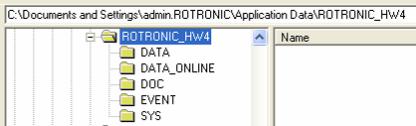
Location of the HW4 User Folder
During the initial startup, HW4 creates a User Folder named ROTRONIC_HW4. By default, this folder is created in C:\Documents and Settings\Windows User\Application Data, where Windows User is the name that was used to log into the current Windows session.
This folder is used to hold the HW4 configuration file as well as the different data, event and protocol files created by HW4.
Windows automatically gives Windows User exclusive access to the directory C:\Documents and Settings\Windows User and subfolders. For this reason, the default path for the HW4 user folder may not be suitable for the intended use of HW4.
For instructions about changing the path of the HW4 User Folder, see Relocating the HW4 User Folder before installing HW4.
© 2008; Rotronic AG |
E-M-HW4v2-Main_13 |
E-M-HW4v2-Main_13 |
Rotronic AG |
|
Bassersdorf, Switzerland |
||
|
||
Document code |
Unit |
|
|
|
|
HW4 software v.2 General instructions and functions |
Instruction Manual |
|
common to all devices |
Document Type |
|
|
||
|
|
|
Document title |
Page 14 of 165 |
|
|
||
|
|
Running HW4 from several workstations with a Windows 2003 server
Generally, we do not recommend installing HW4 directly on a Windows 2003 file server. When you wish to run HW4 on multiple workstations viewing and sharing the same data, you should proceed as follows:
Log in on one of the workstations as an administrator of the Windows 2003 server. Install HW4 on the workstation following the procedure described under Installing HW4
After installing HW4 and prior to starting HW4, go to the HW4 installation directory on the workstation and change the path used by HW4 to locate the HW4 User Folder to the root directory of a file server drive that is mapped on each workstation (see Relocating the HW4 User Folder).
Start HW4 following the procedures described in this manual under Initial Startup Close HW4 before installing HW4 on the next workstation
Repeat this procedure for each workstation
Note: It is important to distinguish between a Windows workstation user and a HW4 user. It is equally important to distinguish between the Windows permissions to a folder and HW4 rights. When the HW4 User Folder is located on the File server and is shared by all workstations, you should give all Windows users sufficient permissions to the HW4 User Folder and subfolders (Folder Properties - Security).
4.3Installing HW4
Insert the HW4 CD-ROM into the CD drive or your PC. The installation program should start automatically. If the installation program does not start, use My Computer in Windows to open the CD drive and double click on the file start.exe located in the root directory of the CD.
© 2008; Rotronic AG |
E-M-HW4v2-Main_13 |

E-M-HW4v2-Main_13 |
Rotronic AG |
|
Bassersdorf, Switzerland |
||
|
||
Document code |
Unit |
|
|
|
|
HW4 software v.2 General instructions and functions |
Instruction Manual |
|
common to all devices |
Document Type |
|
|
||
|
|
|
Document title |
Page 15 of 165 |
|
|
||
|
|
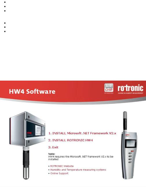
IMPORTANT: HW4 requires a PC with the Microsoft .NET Framework version 2.0 or higher installed. If the Microsoft .NET Framework is not already installed on your PC, please click with the mouse on step 1 to install the framework.
Note: save your work and close all open files because the computer will have to restart to complete the installation process.
After installing the Microsoft .NET Framework, click on step 2 with the mouse to install HW4. Installation begins with the following form:
Click on the NEXT button:
© 2008; Rotronic AG |
E-M-HW4v2-Main_13 |

E-M-HW4v2-Main_13 |
Rotronic AG |
|
Bassersdorf, Switzerland |
||
|
||
Document code |
Unit |
|
|
|
|
HW4 software v.2 General instructions and functions |
Instruction Manual |
|
common to all devices |
Document Type |
|
|
||
|
|
|
Document title |
Page 16 of 165 |
|
|
||
|
|
Click on the NEXT button to move through the different installation steps and follow the instructions provided on the screen.
The choice made above determines how the HW4 install program will make entries in the Windows registry (entries for all users or for the current user only).
The default installation directory is C:\Program Files\HW4 and can be changed during installation.
The shortcut HW4 is automatically created on the desktop during installation:
© 2008; Rotronic AG |
E-M-HW4v2-Main_13 |

E-M-HW4v2-Main_13 |
Rotronic AG |
|
Bassersdorf, Switzerland |
||
|
||
Document code |
Unit |
|
|
|
|
HW4 software v.2 General instructions and functions |
Instruction Manual |
|
common to all devices |
Document Type |
|
|
||
|
|
|
Document title |
Page 17 of 165 |
|
|
||
|
|
Note: Upon starting HW4 for the first time, the folder ROTRONIC_HW4 will be automatically created in C:\Documents and Settings\Windows User\Application Data, where Windows User is the name that was used to log into the current Windows session.
When installation is complete, the following screen should appear:
STOP HERE!
Do not start using HW4 without reading the following:
●Relocating the HW4 User Folder
●Preparing for device connection
© 2008; Rotronic AG |
E-M-HW4v2-Main_13 |
E-M-HW4v2-Main_13 |
Rotronic AG |
|
Bassersdorf, Switzerland |
||
|
||
Document code |
Unit |
|
|
|
|
HW4 software v.2 General instructions and functions |
Instruction Manual |
|
common to all devices |
Document Type |
|
|
||
|
|
|
Document title |
Page 18 of 165 |
|
|
||
|
|
4.4Updating HW4 to a newer version
When updating HW4 to a newer version, two distinct situations may present themselves. In both cases, it is advisable to make a note of your old HW4 product key prior to updating, even if in principle re-entering this information and registering the new version of HW4 are not required.
4.4.1Partial update: HW4.exe
In the case of a partial update, simply copy the new HW4.exe file over the old file, normally located in the directory C:\Program Files\HW4.
4.4.2Full update: Install_HW4.exe
In the case of a full update, you should first uninstall the old version of HW4. To do this properly, click on Start in Windows and open the Control Panel. Select Add or Remove Programs. ROTRONIC HW4 should be listed as one of the installed programs. Select ROTRONIC HW4 and click on the Remove button.
Note: uninstalling HW4 from the Windows Control Panel does not delete the HW4 User Folder.
IMPORTANT: do not delete the HW4 User Folder (ROTRONIC_HW4) created by the old HW4 version. Unless otherwise mentioned, this folder can be used with the updated HW4.
The default path of the HW4 User Folder is C:\Documents and Settings\XXXX\Application Data, where XXXX is the Windows user who initially installed HW4.
Deleting the HW4 User Folder would erase all users, all configuration and measurement data as well as all event tracking and protocols. It is advisable to make a temporary back-up copy of this folder.
4.5Uninstalling HW4 (full uninstall)
IMPORTANT: Not following this procedure may result in problems if HW4 is installed again.
To properly uninstall HW4 and remove its main components, you should click on Start in Windows and open the Control Panel. Select Add or Remove Programs. ROTRONIC HW4 should be listed as one of the installed programs. Select ROTRONIC HW4 and click on the Remove button.
To complete a full uninstall you should manually delete the HW4 User Folder (ROTRONIC_HW4). The default path of the HW4 User Folder is C:\Documents and Settings\XXXX\Application Data, where XXXX is the Windows user who initially installed HW4.
© 2008; Rotronic AG |
E-M-HW4v2-Main_13 |
E-M-HW4v2-Main_13 |
Rotronic AG |
|
Bassersdorf, Switzerland |
||
|
||
Document code |
Unit |
|
|
|
|
HW4 software v.2 General instructions and functions |
Instruction Manual |
|
common to all devices |
Document Type |
|
|
||
|
|
|
Document title |
Page 19 of 165 |
|
|
||
|
|
5 CONNECTING DEVICES TO THE HW4 PC
5.1Definition: masters and slaves (HW4 Professional)
HW4 Professional makes use of the following definitions:
Master: any device / docking station that is directly connected either to a physical or to a virtual port of the PC or that is directly connected to an Ethernet port (TCP/IP) either by cable or by wireless.
Slave: any device / docking station that is connected to a master by means of an RS-485 multi-drop. Slaves cannot be used in conjunction with HW4 Standard Edition.
5.2Connection methods for master devices
All versions of HW4 are compatible with the following methods for connecting devices to the HW4 PC:
●Physical serial port
●Bluetooth serial port (virtual COM port)
●USB port
●LAN (TCP/IP) - cable or wireless connection
5.3Devices used as RS-485 slaves (HW4 Professional)
HW4 Professional allows the use of one RS-485 multi-drop with each master device. Any RS-485 multi-drop is limited to a maximum of 64 devices (1 master and up to 63 slaves). Any device with a RS-485 port can be used either as a master or a slave, without special configuration.
IMPORTANT:
oRS-485 compatibility: the communications protocol used by the products based on the AirChip 3000 technology is not compatible with the protocol used by the previous generation of ROTRONIC products. Do not connect legacy products and AirChip 3000 products to the same RS-485 multi-drop network. HW4 is compatible with both AirChip 3000 products and legacy products as long as these products are connected to separate RS-485 multi-drop network.
oBaud rate: unlike legacy products, the 19200 Baud rate used by all products based on the AirChip 3000 cannot be changed
© 2008; Rotronic AG |
E-M-HW4v2-Main_13 |

E-M-HW4v2-Main_13 |
Rotronic AG |
|
Bassersdorf, Switzerland |
||
|
||
Document code |
Unit |
|
|
|
|
HW4 software v.2 General instructions and functions |
Instruction Manual |
|
common to all devices |
Document Type |
|
|
||
|
|
|
Document title |
Page 20 of 165 |
|
|
||
|
|
|
Example: slaves connected to an Ethernet master |
|
|
LAN (TCP/IP) |
|
|
|
|
|
|
|
|
|
|
|
|
|
|
|
|
|
Network |
|
IP Addr.1 |
|
IP Addr. 2 |
|||
Interface |
|
RS485 |
|
RS485 |
|||
Card |
|
|
|||||
|
|
|
|
|
|
||
PC (HW4) |
|
RS Addr. 1 |
|
RS Addr. 1 |
|||
|
|
|
|
|
|
||
|
|
|
|
|
|
|
|
Note: each device directly connected to the LAN should have a unique IP address and must meet the compatibility requirements of the LAN.
RS-485 multi-drop: up to 1000m (3300 ft)
RS485: 2 wires
IP Addr. n
RS485
RS Addr. 1
Slave
RS485
RS Addr. 2
Slave
RS485
RS Addr. 64
See RS-485 slaves: address and Baud rate requirements.
© 2008; Rotronic AG |
E-M-HW4v2-Main_13 |
E-M-HW4v2-Main_13 |
Rotronic AG |
|
Bassersdorf, Switzerland |
||
|
||
Document code |
Unit |
|
|
|
|
HW4 software v.2 General instructions and functions |
Instruction Manual |
|
common to all devices |
Document Type |
|
|
||
|
|
|
Document title |
Page 21 of 165 |
|
|
||
|
|
6 PREPARING FOR DEVICE CONNECTION
NOTE:
o The HygroLog NT requires a docking station to provide an interface with the PC.
oIf you want to run HW4 on multiple workstations connected to a Windows 2003 file server, use only devices connected by Ethernet (wired or wireless) because this is the only type of connection that can be shared by all workstations. Devices connected by RS-485 to an Ethernet device can also be shared.
6.1Physical serial port
Connecting an instrument or device to a physical COM port of the HW4 PC does not require any preparation. Simply connect the device to any available serial (COM) port on the PC.
6.2Bluetooth virtual serial port
Note: This connection method is available only with some HygroLog NT models. Check the local menu of the HygroLog NT - Settings, and make sure that Bluetooth is on.
Communication via Bluetooth requires the HW4 PC to be equipped with an internal or external Bluetooth transceiver. Connect your Bluetooth transceiver to the HW4 PC and install the driver supplied with the transceiver as per the instructions of the transceiver manufacturer.
Typically, the Bluetooth driver has provisions for defining one or several Bluetooth serial ports (look for Local Services and / or Bluetooth Client Applications). Bluetooth serial ports are virtual COM ports and should be given a number that is distinct from the physical COM ports already present on the PC. Both the transceiver attached to the PC and the HygroLog NT should be given a unique COM port number.
In addition, it is usually necessary to “pair” the transceiver with the Bluetooth enabled HygroLog NT. For security reasons, the process of “pairing” requires a password to be entered. By default, all ROTRONIC
Bluetooth devices are identified as HygroBlue and use 1234 as the pairing password.
In order to allow detection by HW4, any Bluetooth serial port must be manually declared in HW4 Global Settings – General Tab in the text box labeled Bluetooth serial ports, and then discovered manually using Search for RS-232 masters under Devices and Groups in the HW4 main menu bar.
HW4 detects and displays a Bluetooth device in the same manner as any device connected to the PC by way of a physical serial port.
6.3USB port
Prior to connecting any ROTRONIC device to a USB port you should install the ROTRONIC USB driver on the HW4 PC.
IMPORTANT: do not run HW4 while installing the USB driver on the PC.
The ROTRONIC USB driver (ROTRONIC USB Option) can be installed before or after installing HW4.
The following example shows how to install the driver with Windows XP.
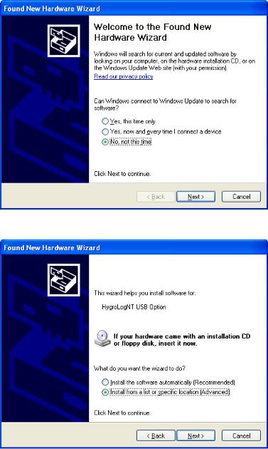
1.Prior to connecting the device to the PC, insert the HW4 CD-ROM in any available PC drive. The HW4 installation screen starts automatically. Exit this screen.
2.Connect the instrument or docking station to any available USB port. Upon detecting the presence of a device connected to the USB port, Windows XP automatically starts the following wizard:
© 2008; Rotronic AG |
E-M-HW4v2-Main_13 |
E-M-HW4v2-Main_13 |
Rotronic AG |
|
Bassersdorf, Switzerland |
||
|
||
Document code |
Unit |
|
|
|
|
HW4 software v.2 General instructions and functions |
Instruction Manual |
|
common to all devices |
Document Type |
|
|
||
|
|
|
Document title |
Page 22 of 165 |
|
|
||
|
|
If you are using Windows XP Professional SP2, the following screen appears. Select “No, not this time” and click on Next. This screen does not appear if you have not installed SP2.
3. The following screen appears:
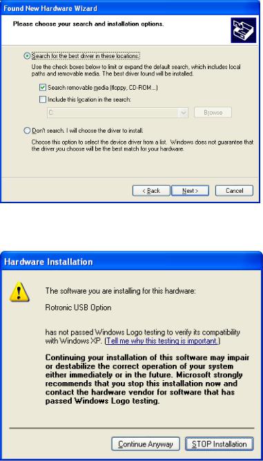
Select “Install from a list or specific location” and click on Next.
© 2008; Rotronic AG |
E-M-HW4v2-Main_13 |
E-M-HW4v2-Main_13 |
Rotronic AG |
|
Bassersdorf, Switzerland |
||
|
||
Document code |
Unit |
|
|
|
|
HW4 software v.2 General instructions and functions |
Instruction Manual |
|
common to all devices |
Document Type |
|
|
||
|
|
|
Document title |
Page 23 of 165 |
|
|
||
|
|
4. Select “Search for the best driver in these locations”. Note that at this time the HW4 CD_ROM should have been already inserted in the PC.
Click on Next
5. You will receive the following warning. Disregard this warning and click on “Continue anyway”.
© 2008; Rotronic AG |
E-M-HW4v2-Main_13 |
E-M-HW4v2-Main_13 |
Rotronic AG |
|
Bassersdorf, Switzerland |
||
|
||
Document code |
Unit |
|
|
|
|
HW4 software v.2 General instructions and functions |
Instruction Manual |
|
common to all devices |
Document Type |
|
|
||
|
|
|
Document title |
Page 24 of 165 |
|
|
||
|
|
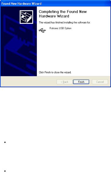
6. Windows copies the USB driver located on the HW4 CD-ROM and displays the following message when done:
Click on “Finish” to complete the process.
Note: If your device has only a serial port and the PC has a USB port but no COM port, you can install a USB Serial Adapter on one of the PC USB ports. In this situation, install the driver supplied with the USB serial adapter (not the driver supplied with HW4) and connect the device to this adapter. HW4 will assume that the device is connected to a serial (COM) port.
6.4Ethernet (TCP/IP) connection
NOTES:
ROTRONIC devices with an Ethernet interface require configuration of the TCP/IP settings to ensure compatibility with the LAN to which the HW4 PC is connected (IP address, sub-net mask, gateway, etc.). Detailed instructions for configuring a ROTRONIC device with Ethernet (TCP/IP) interface are provided separately in document IN-E-TCPIP-Conf_11. A PDF version of this document can be downloaded from our web site. You may also want to read “Basic TCP/IP concepts” in this manual or consult with your network administrator prior to connecting any device to your local area network.
ROTRONIC devices with an Ethernet interface (both wired and wireless) are shipped with a Device Configuration Certificate that provides information about the factory configuration settings of both the Ethernet module and device.
© 2008; Rotronic AG |
E-M-HW4v2-Main_13 |
E-M-HW4v2-Main_13 |
Rotronic AG |
|
Bassersdorf, Switzerland |
||
|
||
Document code |
Unit |
|
|
|
|
HW4 software v.2 General instructions and functions |
Instruction Manual |
|
common to all devices |
Document Type |
|
|
||
|
|
|
Document title |
Page 25 of 165 |
|
|
||
|
|
Before configuring the device TCP/IP settings, you should make sure that the following is available to you:
o An unused static IP address that is compatible with your network o The subnet mask of your network
oThe local IP address of the router used on the same LAN as the HW4 PC, the default gateway used by all devices on the LAN
In addition, the following information is required for a wireless connection:
o The wireless network name (SSID)
oThe security mode (WAP, WEP or other) used by the HW4 network and the key or keys used by the security mode.
6.4.1Wired TCP/IP connection
A device discovery utility (Digi Device Discovery) is provided in the HW4 installation directory (usually, C:\Program Files\HW4). The name of the corresponding file is dgdiscvr.exe. The Digi Device Discovery utility can be started by double clicking with the mouse on the file.
Digi Device Discovery detects only products from Digi International such as the internal Ethernet module currently used by ROTRONIC for devices with an Ethernet interface.
Connect the device to be configured to your LAN and double click with the mouse on dgdiscvr.exe to start Digi Device Discovery.
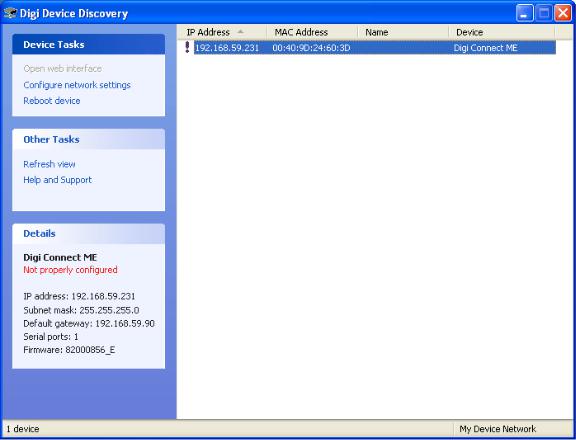
When activated, Digi Device Discovery automatically detects any ROTRONIC device present on the LAN and provides a list of all such devices.
The following example shows the initial screen for a device with TCP/IP settings that are not compatible with the LAN. Note the red warning that appears on the left side of the screen when the device is selected (highlighted).
© 2008; Rotronic AG |
E-M-HW4v2-Main_13 |
E-M-HW4v2-Main_13 |
Rotronic AG |
|
Bassersdorf, Switzerland |
||
|
||
Document code |
Unit |
|
|
|
|
HW4 software v.2 General instructions and functions |
Instruction Manual |
|
common to all devices |
Document Type |
|
|
||
|
|
|
Document title |
Page 26 of 165 |
|
|
||
|
|
With the device highlighted, click on “Configure network settings” to open the dialog box shown below.
© 2008; Rotronic AG |
E-M-HW4v2-Main_13 |

E-M-HW4v2-Main_13 |
Rotronic AG |
|
Bassersdorf, Switzerland |
||
|
||
Document code |
Unit |
|
|
|
|
HW4 software v.2 General instructions and functions |
Instruction Manual |
|
common to all devices |
Document Type |
|
|
||
|
|
|
Document title |
Page 27 of 165 |
|
|
||
|
|
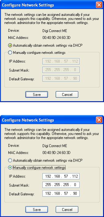
When in doubt as to which setting to enter manually, select “automatically obtain network settings via DHCP” (requires a LAN with DHCP server such as a router). Using DHCP ensures that the device settings that are compatible with the LAN (subnet mask and default gateway) and that the IP address does not generate any conflict.
Click on Save, Reboot the device and click on Refresh View.
A dynamic IP address is subject to change whenever the device is powered down and then powered up. For this reason, you should now change the device configuration from dynamic IP address (DHCP) to static IP address. To do this, click again on “Configure network settings”. The current settings of the device (IP address, subnet mask, etc.) appear in light gray.
© 2008; Rotronic AG |
E-M-HW4v2-Main_13 |
E-M-HW4v2-Main_13 |
Rotronic AG |
|
Bassersdorf, Switzerland |
||
|
||
Document code |
Unit |
|
|
|
|
HW4 software v.2 General instructions and functions |
Instruction Manual |
|
common to all devices |
Document Type |
|
|
||
|
|
|
Document title |
Page 28 of 165 |
|
|
||
|
|
Click on “Manually configure network settings”.
Change the device IP address to an address that is both currently unused on the LAN and outside of the range of dynamic IP addresses used by the DHCP server. To select a proper address, you may want to consult your network administrator.
© 2008; Rotronic AG |
E-M-HW4v2-Main_13 |

E-M-HW4v2-Main_13 |
Rotronic AG |
|
Bassersdorf, Switzerland |
||
|
||
Document code |
Unit |
|
|
|
|
HW4 software v.2 General instructions and functions |
Instruction Manual |
|
common to all devices |
Document Type |
|
|
||
|
|
|
Document title |
Page 29 of 165 |
|
|
||
|
|
6.4.2Wireless TCP/IP connection
The internal Digi module WI-ME used by wireless ROTRONIC devices does not allow a wired connection to a LAN and must be configured using a wireless connection.
To allow a new wireless device to connect, the HW4 network wireless router has to be temporarily reconfigured and the wireless network security disabled. This is clearly not practical for most users and we recommend using a dedicated wireless router for the purpose of configuring a wireless ROTRONIC device.
Detailed instructions for configuring a wireless Ethernet ROTRONIC device are provided separately in document IN-E-TCPIP-Conf_11. A PDF version of this document can be downloaded from our web site.
6.5RS-485 slaves: address and Baud rate requirements
IMPORTANT:
oRS-485 compatibility: The communications protocol used by the products based on the AirChip 3000 technology is not compatible with the protocol used by the previous generation of ROTRONIC products. Do not connect legacy products and AirChip 3000 products to the same RS-485 multi-drop network.
o Baud rate: the 19200 Baud rate used by all products based on the AirChip 3000 cannot be changed
All devices that are compatible with HW4 have an internal RS-485 address ranging from 0 to 64. The factory default for the RS-485 address is 0. Similarly, devices are configured at the factory to use a specific Baud rate for all serial communications. In the case of devices with an internal Ethernet (TCP/IP) module, serial communication includes communication between the device proper and it internal Ethernet module.
The RS-485 address is part of the communications protocol used by HW4 and is always included in the command sent to a device and in the device response. In the case of an RS-485 multi-drop, this address is used to identify each device and should be unique within the same multi-drop.
Example: slaves connected to a COM or USB master
RS232: 3 wires (including ground wire)
RS485: 2 wires
PC (HW4) |
|
RS232 or |
Slave |
Slave |
|
||||
|
|
USB |
|
|
COM Port
or Address 1 Address 2 Address 64 USB port
|
|
|
|
RS485 |
|
RS485 |
RS485 |
||||||
|
|
|
|
|
|
|
|
|
|
|
|
|
|
|
|
|
|
|
|
|
|
|
|||||
up to 150m (490 ft) |
|
RS-485 multi-drop: up to 1000m (3300 ft) |
|
|
|||||||||
|
|
|
|
|
|
|
|
HW4 Professional only |
|
|
|||
|
|
|
|
|
|
|
|
|
|
|
|
|
|
© 2008; Rotronic AG |
E-M-HW4v2-Main_13 |
E-M-HW4v2-Main_13 |
Rotronic AG |
|
Bassersdorf, Switzerland |
||
|
||
Document code |
Unit |
|
|
|
|
HW4 software v.2 General instructions and functions |
Instruction Manual |
|
common to all devices |
Document Type |
|
|
||
|
|
|
Document title |
Page 30 of 165 |
|
|
||
|
|
When searching for RS-485 slaves, HW4 automatically changes the factory default RS-address of both masters and slaves as explained below:
oMasters: HW4 automatically changes the RS-485 address of any new device that is directly connected to the PC (master) from 0 to 1. As a result, all masters discovered by HW4 end up having the same RS485 network address (1).
oSlaves: in the situation where an RS-485 multi-drop is detected during a search, HW4 automatically changes the address of each slave with address 0 to a unique address ranging from 2 to 64. The same address range (2 to 64) is used again when there is more than one RS-485 multi-drop.
IMPORTANT:
oAvoid changing manually the factory default RS address (0) of new devices. Allow HW4 to change this address automatically.
oChange manually the RS address to 0 in the following situations:
-A master will now be used as a slave
-A slave is being moved from one multi-drop to another.
The change of address should be done prior to changing the physical connection (use HW4 Device Manager). If you forgot to do this, temporarily connect the device as a master to do the address change.
oDuplicate RS addresses are not permitted within the same RS-485 multi-drop (with the exception of temporary address 0). Duplicate addresses may prevent communication with the devices or give unpredictable results. It is OK to use the same RS address in different multi-drops.
oAll devices within a multi-drop must use the same baud rate. Different Baud rates will prevent communication between the devices and the HW4 PC.
Master with Ethernet (TCP/IP) interface: any change to Baud rate of the device done with HW4 Device Manager should also be reflected in the configuration of the internal Digi International module used by the device to connect to the LAN.
See: Changing the baud rate of an Ethernet device
© 2008; Rotronic AG |
E-M-HW4v2-Main_13 |
 Loading...