


Short instruction manual
Digital transmitter for humidity & temperature
Duct & Wall and Cable version
Congratulations on your purchase of the new state-of-the-art HygroFlex5-series transmitter. Please read these short instructions carefully before installing the device
General description
The HygroFlex5-series devices are universal transmitters for transmission of humidity and temperature measurements. Compatible with all interchangeable HC2 probes. These short instructions are limited to a description of the main functions and installation of the device.
The detailed instruction manual can be found on the internet at: www.rotronic-humidity.com
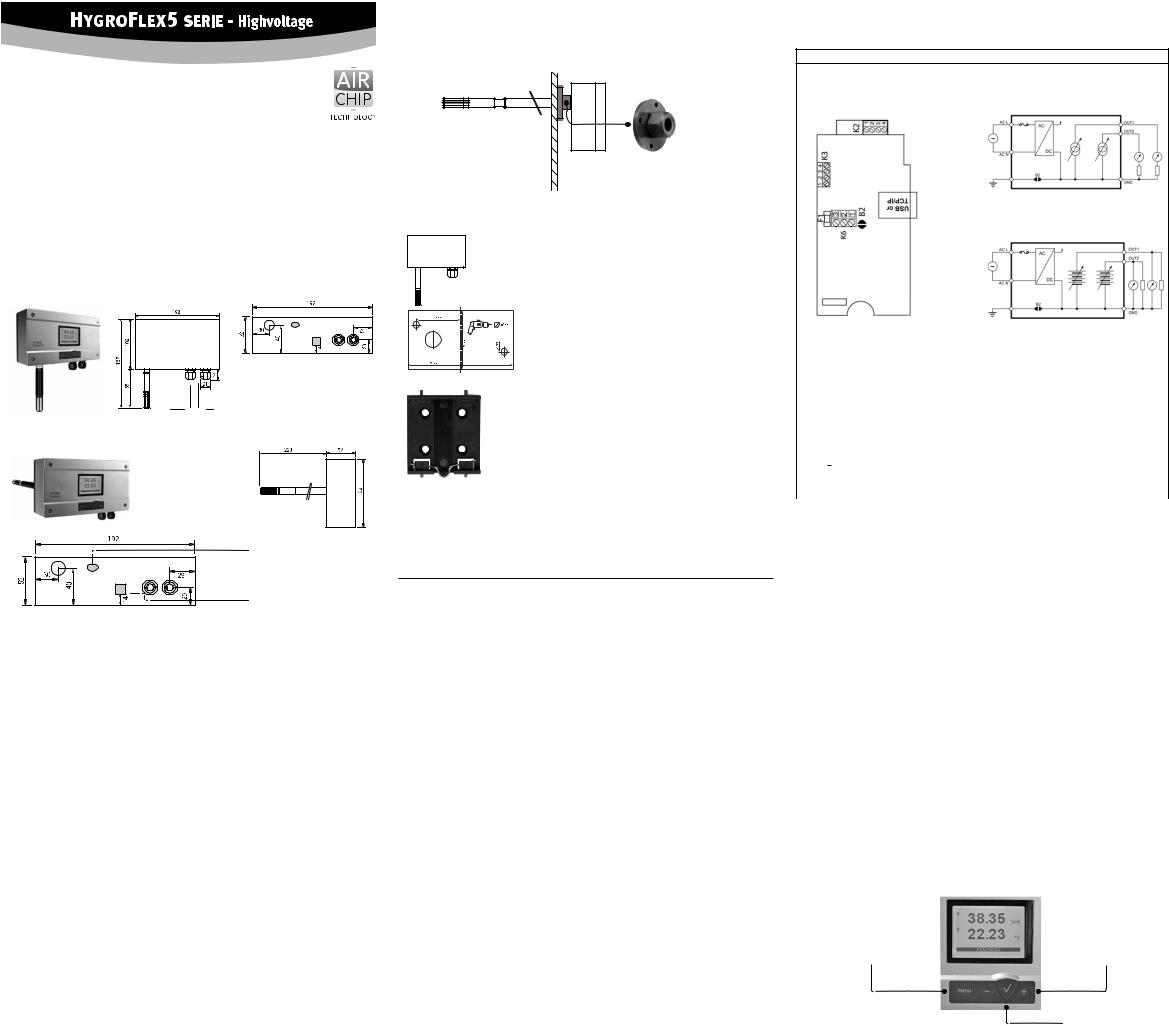
Dimensions / Connections
Wall version (Type W)
Power Signal
Duct version (Type D)
Service interface (Mini-USB)
Digital connection
Mechanical installation
General recommendations
Relative humidity is extremely temperature-dependent. In order to measure it exactly, the probe and sensors must be set exactly on the temperature level of the environment that is to be measured.
The installation site can therefore have a significant influence on the performance of the device.
Follow the guidelines below to ensure optimum performance:
a)Select a representative installation site: Install the probe at a point where the humidity, temperature and pressure conditions are representative for the environment that is to be measured.
b)Make sure there is sufficient air movement around the probe: An air flow of at least 1 metre/ second accelerates and facilitates adjustment of the probe to changing temperatures.
c)Avoid:
1.Probe too close to heating elements, cooling coils, cold or hot walls, direct sunlight, etc.
2.Probe too close to steam, injectors, humidifiers or direct precipitation.
3.Unstable pressure conditions with high air turbulence.
d)Insert the probe as far as possible into the environment that is to be measured.
e)Avoid accumulation of condensation at the contact wires of the sensor. Install the probe so that the tip points down. If that is not possible, install it in horizontal position.
Mounting the duct version (Type D)
To avoid measurement errors, at least 200 mm of the probe should be inserted into the environment that is to be measured.
If necessary, use the mounting flange AC5005 to install the probe.
AC5005 Mounting flange for 15 mm probe
Mounting the wall version
Alignment
Mount the transmitter so that the probe points down.
Mounting variant 1
Drill the necessary holes using the drill template drawn on the packaging. Then insert the plugs delivered with the device and mount the transmitter with the screws.
Mounting variant 2
If there is a TS35 DIN top-hat rail available, the transmitter can be clipped on to the top-hat rail directly with the help of the mounting kitAC5002 (available as optional extra). For this, the DIN holders
(a kit has two holders and eight screws) are screwed directly on to the predrilled holes in the transmitter.
Electrical installation
Power supply
3-wire galvanicseparated with analogue outputs: 85 to 240 VAC.
When both outputs are connected, the maximum current consmption is 50 mA.
Supply voltage / Technology
Type |
Supply voltage V+ |
load |
output |
3 / 4-wire |
|
|
|
|
|
|
|
HF561 |
85…240 VAC |
Max. 500 Ω |
0...20 mA |
HF562 |
85…240 VAC |
Max. 500 Ω |
4...20 mA |
HF563 |
85…240 VAC |
Min. 1000 Ω |
0...1 V |
HF564 |
85…240 VAC |
Min. 1000 Ω |
0...5 V |
HF565 |
85…240 VAC |
Min. 1000 Ω |
0...10 V |
A Caution: Wrong supply voltages and excessively high loading of the outputs can damage the transmitter.
Terminal configuration /Connection diagrams
The type is defined using the table Supply voltage / Technology to then use the following connection diagrams:
3 / 4 wire circuit / HF56x
|
|
|
|
|
Current output |
|
|
|
|
|
|
Voltage output |
|
|
|
|
|
|
|
|
Terminal |
Description |
|
||||
K2-1: OUT1 |
Analogue humidity output + |
|
||||
|
|
|
|
|
|
|
K2-2: OUT2 |
Analogue temperature output + |
|
||||
K2-3: GND |
Ground (tied with other GND) |
|
||||
K2-4: GND |
Ground (tied with other GND) |
|
||||
K3-1: PWR |
not used |
|
||||
K3-2: GND |
Ground (tied with other GND) |
|
||||
K3-3: D+ |
RS-485 Bi-directional TX– / RX – |
|
||||
K3-4: D– |
RS-485 Bi-directional TX+ / RX + |
|
||||
K6-1: |
|
|
|
|
Protective ground |
|
|
|
|||||
|
|
|
|
|
||
K6-2: + DC+ / AC L |
Power supply phase, 85…240 VAC |
|
||||
K6-3: – DC– / AC N |
Power supply neutral, 85…240 VAC |
|
||||
Terminal K6-1: Earth is usually connected to GND. If this is not wanted, a pad on the PCB (B2) must be removed.
Terminals K3 (RS-485): Terminals K3-1 and K3-2 can be used to feed the device (multi-point connection). Several RS-485 devices can be operated with a strong 15 VDCpower supply unit. In this case the supply voltage at K6-1 to K6-3 is not used.
Warning: Make sure that all settings have been made correctly before integrating and connecting the transmitters in the network.
Programming
The basic settings of the devices are made in the factory according to your order. The transmitters are adjusted in the factory and therefore do not need to be checked and readjusted during installation. The devices can be started immediately after installation.
Display / Keypad
The LC display has a backlight which can be set to be on all the time or whenever a key is pressed. The backlight can also be disabled.
Press the Enter button to switch between 2 and 3-line display.
The display can also be configured to show a trend indicator on each line:
▲: increasing value ▼: decreasing value
In the event of an alarm “Sensor Alarm” appears on the bottom of the display.
Unity system can be switched between Metric and English.
|
|
Menu navigation |
|
Button MENU |
|||
|
Buttons + / - change value |
||
open / close menu |
|
||
|
increase/decrease |
||
|
|
||
|
|
|
|
|
|
|
|
|
|
Button ENTER |
|
|
|
select menu point |
|
|
|
|
Note: Unauthorised use of the menu can be prevented by locking the setting “Display Menu”
(using the HW4 software > Device Manager > Display).
Sources of error
Measured values can be influenced by the following factors:
Temperature errors :
Adaptation time too short, cold outside wall, heating elements, sunlight, etc.
Humidity errors:
Steam, water spray, dripping water or condensation at the sensor, etc. Repeatability and long term stability are, however, not influenced by these factors even if the probe is exposed to high humidity or saturation with steam (condensation) over a longer period of time.
Soiling:
By dust in the air. The choice of probe filter depends on the amount of soiling at the measuring point. The filter must be cleaned or replaced periodically.
Scaling / Adjustment / Firmware update
The following settings can be made with the help of the HW4 software and either the service cable
AC3006 or AC3009:
•new scaling of the outputs
•adjustment
•firmware update
You can find a detailed description in the manual that you can download from our web site at www.rotronic-humidity.com
Periodic calibration of the probe / transmitter
BoththePt100RTDtemperaturesensorandthecorrespondingelectronicsareverystableanddo not normally need to be changed or calibrated after factory calibration. The long term stability of the ROTRONICHygromer® humidityprobesistypicallybetterthan1%rhperyear.Formaximumaccuracy we recommend calibration of the probe about every six to 12 months. More frequent calibration can be necessary in applications where the sensor is exposed to pollutants. The calibration can be performed by the user himself on site or in the laboratory / workshop. For routine calibrations the probe should be checked at one or two points.
The electronics of the transmitter do not normally require calibration in the field. They can be checked easily with the help of the probe simulator in the HW4 software package. The electronics cannotberepairedinthefieldandshouldbereturnedtothemanufacturerinthecaseofproblems.
For details on calibration, please see the full version of the instruction manual, which you can download from the internet.
Technical data (measurement)
Humidity: |
0...100 %rh |
Temperature: |
Probe dependent: -50...100°C |
Accuracy: |
Probe dependent: ±0.8 %rh, ± 0.1 K @ 23°C |
Protection: |
IP65 except for models with USB and Ethernet interface |
Outputs: |
Current or voltage signals, digital output depending on order code, |
|
UART service interface |
Technical data (operation) |
|
Temperature: |
–40...60 °C/ Models with display –10...60 °C |
Humidity: |
0...100 %rh, non-condensing |
Technical data probe
Depending on type
ROTRONIC AG, CH-8303 Bassersdorf |
|
|
Tel. +41 44 838 11 44, www.rotronic.com |
|
|
ROTRONIC Messgeräte GmbH, D-76275 Ettlingen |
|
|
Tel. +49 7243 383 250, Fax +49 7243 383 260, www.rotronic.de |
|
|
ROTRONIC SARL, 56, F - 77183 Croissy Beaubourg |
|
|
Tél. +33 1 60 95 07 10, www.rotronic.fr |
|
|
Rotronic Italia srl, I-20157 Milano |
|
|
Tel. +39 2 39 00 71 90, Fax (+39) 02 33 27 62 99, www.rotronic.it |
|
|
ROTRONIC Instruments (UK) Ltd, Crompton Fields, |
|
|
Phone +44 1293 571000, www.rotronic.co.uk |
|
|
ROTRONIC Instrument Corp, NY 11788, USA |
|
|
Phone +1 631 427-3898, www.rotronic-usa.com |
02 |
|
ROTRONIC South East Asia Pte Ltd, Singapore 339156 |
||
0 |
||
Phone +65 6294 6065, www.rotronic.com.sg |
||
973.0 |
||
ROTRONIC Shanghai Rep. Office, Shanghai 200233, China |
||
Phone +86 40 08162018, www.rotronic.cn |
12.0 |
|
|
Kurzbedienungsanleitung
Digitaler Messumformer für Feuchteund Temperatur
Wand- / Kabelund Kanalversion
Herzlichen Glückwunsch zum Kauf Ihres neuen HygroFlex5-Serie Messumformers. Sie haben damit ein dem neuesten Stand der Technik entsprechendes Gerät erworben. Bitte lesen Sie diese
Anleitung genau durch, bevor Sie das Gerät installieren.
Allgemeine Beschreibung
Die HygroFlex5-Serie Geräte sind universelle Messumformer, für die Übertragung von Feuchteund Temperaturmesswerten. Diese Kurzbedienungsanleitung beschränkt sich auf die Beschreibung der wichtigsten Funktionen und der Installation des Gerätes. Die detaillierte Bedienungsanleitung finden Sie im Internet unter: www.rotronic-humidity.com
Abmessungen / Anschlüsse
Wandausführung (Typ W)
Speisung Signal
Kanalausführung (Type D)
Service Schnittstelle (Mini-USB)
Digital Anschluss
Mechanische Installation
Allgemeine Empfehlungen
Die relative Feuchte ist extrem temperaturabhängig. Deren exakte Messung erfordert, dass Fühler und der Sensor genau auf dem Temperaturniveau der zu messenden Umgebung sind. Daher kann der gewählte Installationsort einen bedeutenden Einfluss auf die Leistung des Gerätes haben.
Die Einhaltung der folgenden Richtlinien garantiert Ihnen eine optimale Leistung des Gerätes:
a)Wählen Sie einen repräsentativen Installationsort:
Installieren Sie den Fühler an einem Ort, wo die Feuchte-, Temperaturund Druckverhältnisse für die zu messende Umgebung repräsentativ sind.
b)Stellen Sie genügend Luftbewegung am Fühler sicher:
Eine Luftgeschwindigkeit von mindestens 1 Meter/Sekunde beschleunigt und erleichtert die Anpassung des Fühlers an wechselnde Temperaturen.
c)Zu vermeiden sind:
1.Fühler zu nahe an Heizelement, Kühlschlange, kalter oder warmer Wand und direkte
Sonneneinstrahlung etc.
2.Fühler zu nahe an Dampf-Injektor, Befeuchter oder direkter Niederschlag.
3.Unstabile Druckverhältnisse bei grossen Luftturbulenzen.
d)Tauchen Sie den Fühler so weit als möglich in die zu messende Umgebung ein.
e)Vermeiden Sie die Ansammlung von Kondensat an den Kontaktdrähten des Sensors.
Installieren Sie den Fühler so, dass die Fühlerspitze nach unten zeigt. Wenn dies nicht möglich ist, installieren Sie ihn in horizontaler Position.
Montage der Kabel-/Kanalversion
Zur Vermeidung von Messfehlern sollten mindestens 200 mm des Fühlers in die zu messende Umgebung eingetaucht sein. Verwenden Sie gegebenenfalls den Montageflansch AC5005 um den Fühler zu installieren.
AC5005 Montageflansch für 15mm Fühler
Montage der Wandversion
Ausrichtung
Der Transmitter wird so montiert, dass der Fühler nach unten gerichtet ist.
Montage Variante 1
MitderaufderVerpackungaufgezeichnetenBohrschablonewerden


 die nötigen Löcher gebohrt. Danach werden die mitgelieferten
Dübel eingesetzt um dann den Transmitter mit Hilfe der Schrauben zu montieren.
Montage Variante 2
Bei vorhanden DIN-Hutschienen TS35 kann unter Mithilfe des
Montagekit AC5002 (optional erhältlich) der Transmitter direkt auf die DIN Hutschienen aufgeschnappt werden. Hierzu werden die
DIN-Halterungen (Eine Verpackungseinheit besteht aus 2 Halterungen und 8 Schrauben) direkt auf die vorgebohrten Löcher des Transmitters geschraubt.
Elektrische Installation
Stromversorgung
3-Leiter galvanisch getrennt mit Analogausgängen: 85 bis 240 VAC.
Mit beiden Ausgängen angeschlossen beträgt die maximale Stromaufnahme 50mA.
Versorgungsspannung / Technologie
Typ |
Spannungsversorgung V+ |
Bürde |
Ausgang |
3 / 4 Leiter |
|
|
|
|
|
|
|
HF561 |
85…240 VAC |
Max. 500 Ω |
0...20 mA |
HF562 |
85…240 VAC |
Max. 500 Ω |
4...20 mA |
HF563 |
85…240 VAC |
Min. 1000 Ω |
0...1 V |
HF564 |
85…240 VAC |
Min. 1000 Ω |
0...5 V |
HF565 |
85…240 VAC |
Min. 1000 Ω |
0...10 V |
A Achtung: FalscheVersorgungsspannungensowiezugrosseBelastungenderAusgänge
können den Messumformer beschädigen.
Klemmenbelegung / Anschlussschemata
Anhand der Tabelle Versorgungsspannung / Technologie wird der Typ definiert, um folgende Anschluss-Schemas verwenden zu können:
3 / 4 Leiter Schaltung / HF56x
|
|
|
|
|
Stromausgang |
|
|
|
|
|
Spannungsausgang |
|
|
|
|
|
|
Klemme |
Beschreibung |
||||
|
|
|
|
|
|
K2-1: OUT1 |
Feuchte-Analogausgang + |
||||
K2-2: OUT2 |
Temperatur-Analogausgang + |
||||
K2-3: GND |
GND |
||||
K2-4: GND |
GND |
||||
K3-1: PWR |
Frei |
||||
K3-2: GND |
GND / Spannungsversorgung |
||||
K3-3: D+ |
RS-485 Bi-directional TX– / RX – |
||||
K3-4: D– |
RS-485 Bi-directional TX+ / RX + |
||||
K6-1: |
|
|
|
|
Erde |
|
|||||
|
|
|
|
||
K6-2: + DC+ / AC L |
Spannungsversorgung Phase, 85…240 VAC |
||||
K6-3: – DC– / AC N |
Spannungsversorgung Neutral, 85…240 VAC |
||||
Klemme K6-1: Erde ist standardmässig mit GND verbunden. Wird das nicht gewünscht, muss auf dem PCB das Lötauge B2 entfernt werden.
Klemmen K3 (RS-485): Klemmen K3-1 und K3-2 können verwendet werden, um das Gerät zu speisen (Mehrpunktverbindung). Es können mehrere RS-485 Geräte mit einem starken Netzgerät
15VDCbetrieben werden. In diesem Falle wird die Spannungsversorgung an K6-1 bis K6-3 nicht verwendet.
Warnung: Stellen Sie sicher, dass bevor Sie den Transmitter ins Netzwerk einbinden und anschliessen, alle Einstellungen richtig durchgeführt wurden.
Programmierung
Die Grundeinstellungen der Geräte werden im Werk, gemäss Ihrer Bestellung, vorgenommen. Die Transmitter werden im Werk justiert, sodass eine Überprüfung oder Nachjustierung bei der Installation nicht notwendig ist. Die Geräte können sofort nach der Installation in Betrieb genommen werden.
Display
Das LC-Display hat eine Hintergrundbeleuchtung welche so eingestellt werden kann, dass diese entweder immer an, immer aus ist oder durch drücken einer Taste kurzzeitig aktiviert wird.
Beim Betätigen der Enter-Taste kann zwischen Zweioder Dreizeilen Anzeige gewechselt werden.
Im Display können zusätzlich die Mess-End-Indikatoren für jeden Wert angezeigt werden: ▲: Steigender Wert
▼: Sinkender Wert
Bei einem Alarm wird „Sensor Alarm“ im unteren Displayrand angezeigt.
Systemeinheiten können Metrisch oder Englisch gewählt werden.
|
|
Menünavigation |
|
Taste MENU |
|||
|
Tasten + / - Wert ändern |
||
Menü öffnen /schliessen |
|
||
|
Erhöhen / Verringern |
||
|
|
||
|
|
|
|
|
|
|
|
|
|
Taste ENTER |
|
|
|
Auswahl Menüpunkt |
|
|
|
|
Hinweis: DerunbefugteZugriffaufdasMenükanndurchSperrenderEinstellung“DisplayMenü” verhindert werden (Verwendung der HW4-Software > Geräte-Manager > Display)
Fehlerquellen
Messwerte können durch folgende Einflüsse beeinträchtigt werden:
Temperaturfehler
Durch zu kurze Angleichzeit, kalte Aussenwand, Heizkörper und Sonneneinstrahlung usw.
Feuchtefehler
Durch Dampf, Wasserspritzer, Tropfwasser oder Kondensation am Sensor usw. Jedoch wird die Reproduzierbarkeit und Langzeitstabilität dadurch nicht beeinträchtigt, auch wenn der Fühler über längere Zeit einer hohen Feuchte oder Sättigung mit Wasserdampf (Kondensation) ausgesetzt wurde.
Verschmutzung
Durch Staub in der Luft. Die Wahl des Fühlerfilters ist abhängig vom Verschmutzungsgrad des
Messortes und ist periodisch zu reinigen oder zu ersetzen.
Skalierung / Justierung / Firmware update
Mit Hilfe der HW4 Software und dem Servicekabel AC3006 oder AC3009 können folgende
Einstellungen durchgeführt werden:
•Neuskalierung der Ausgänge
•Justierung
•Firmware update
Eine detaillierte Beschreibung finden Sie im Manual welches Sie im Internet unter: www.rotronic-humidity.com herunterladen können.
Periodische Kalibrierung des Fühlers / Transmitters
Sowohl derPt100 RTDTemperatursensorals auch die dazugehörende Elektroniksind sehrstabil und müssen nach der Werkskalibrierung normalerweise nicht verändert oder kalibriert werden.
Die Langzeitstabilität der ROTRONIC Hygromer Feuchtefühler ist typischerweise besser als 1 %rF pro Jahr. Für eine maximale Genauigkeit empfehlen wir eine Kalibrierung der Fühler ca. alle sechs biszwölfMonate.InAnwendungenwoderSensorSchadstoffenausgesetztist,kanneinehäufigere
Kalibrierung notwendig sein. Die Kalibrierung kann durch den Benutzer selber vor Ort oder im Labor bzw. in der Werkstatt vorgenommen werden. Für RoutineKalibrierungen sollte der Fühler an einem oder zwei Punkten geprüft werden.
Die Elektronik des Transmitters selber erfordert normalerweise keine Kalibrierung im Feld. Sie kann mit der Verwendung eine Fühlersimulators der HW4 Software auf einfache Weise überprüft werden. Die Elektronik lässt sich nicht im Feld reparieren und sollte bei Problemen ans Herstellerwerk retourniert werden. Für die Details der Kalibrierung verweisen wir auf die Vollversion des
Bedienerhandbuches, welche im Internet erhältlich ist.
Technische Daten (Messbereich)
Feuchte: |
0...100 %rF |
Temperatur: |
Fühlerabhängig: –50...100 °Cam Fühler |
Genauigkeit: |
Fühlerabhängig: ± 0.8 %rF, ± 0.1 K @ 23°C |
Schutzart: |
IP65 ausser Modelle mit USB und Ethernet Schnittstelle |
Ausgänge: |
Stromoder Spannungssignal, digitaler Ausgang je nach Bestellcode, |
|
UART-Service-Schnittstelle |
Technische Daten (Einsatzbereich) |
|
Temperatur: |
–40...60 °C/ Modelle mit Anzeige –10...60 °C |
Feuchte: |
0...100 %rF, nicht kondensierend |
Technische Daten Fühler
Fühlerabhängig
ROTRONIC AG, CH-8303 Bassersdorf |
|
|
Tel. +41 44 838 11 44, www.rotronic.com |
|
|
ROTRONIC Messgeräte GmbH, D-76275 Ettlingen |
|
|
Tel. +49 7243 383 250, Fax +49 7243 383 260, www.rotronic.de |
|
|
ROTRONIC SARL, 56, F - 77183 Croissy Beaubourg |
|
|
Tél. +33 1 60 95 07 10, www.rotronic.fr |
|
|
Rotronic Italia srl, I-20157 Milano |
|
|
Tel. +39 2 39 00 71 90, Fax (+39) 02 33 27 62 99, www.rotronic.it |
|
|
ROTRONIC Instruments (UK) Ltd, Crompton Fields, |
|
|
Phone +44 1293 571000, www.rotronic.co.uk |
|
|
ROTRONIC Instrument Corp, NY 11788, USA |
|
|
Phone +1 631 427-3898, www.rotronic-usa.com |
02 |
|
ROTRONIC South East Asia Pte Ltd, Singapore 339156 |
||
0 |
||
Phone +65 6294 6065, www.rotronic.com.sg |
||
973.0 |
||
ROTRONIC Shanghai Rep. Office, Shanghai 200233, China |
||
Phone +86 40 08162018, www.rotronic.cn |
12.0 |
|
|
 Loading...