

Rosemount WPG58 User Manual
Reference Manual
00809-0100-4045, Rev AB
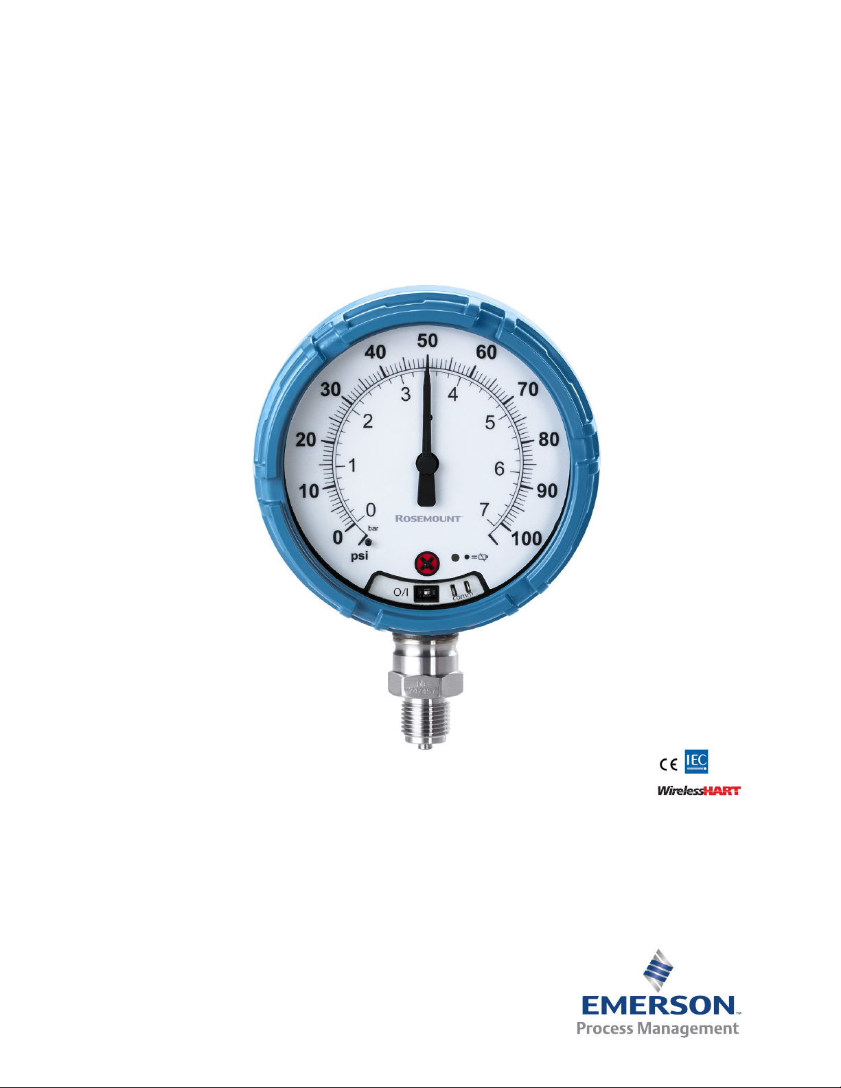
Rosemount™ Wireless Pressure Gauge
with WirelessHART® Protocol
March 2016


Reference Manual
00809-0100-4045, Rev AB
Contents
1Section 1: Introduction
2Section 2: Hardware Installation
Table of Contents
March 2016
1.1 Using this manual. . . . . . . . . . . . . . . . . . . . . . . . . . . . . . . . . . . . . . . . . . . . . . . . . . . . . . 3
1.2 Models covered . . . . . . . . . . . . . . . . . . . . . . . . . . . . . . . . . . . . . . . . . . . . . . . . . . . . . . . 3
1.3 Product recycling/disposal . . . . . . . . . . . . . . . . . . . . . . . . . . . . . . . . . . . . . . . . . . . . . .3
2.1 Overview . . . . . . . . . . . . . . . . . . . . . . . . . . . . . . . . . . . . . . . . . . . . . . . . . . . . . . . . . . . . . 5
2.2 Safety messages. . . . . . . . . . . . . . . . . . . . . . . . . . . . . . . . . . . . . . . . . . . . . . . . . . . . . . . 5
2.3 Considerations . . . . . . . . . . . . . . . . . . . . . . . . . . . . . . . . . . . . . . . . . . . . . . . . . . . . . . . . 6
2.3.1 Pre-installation . . . . . . . . . . . . . . . . . . . . . . . . . . . . . . . . . . . . . . . . . . . . . . . . . . 6
2.3.2 Installation . . . . . . . . . . . . . . . . . . . . . . . . . . . . . . . . . . . . . . . . . . . . . . . . . . . . . . 7
2.3.3 Mechanical . . . . . . . . . . . . . . . . . . . . . . . . . . . . . . . . . . . . . . . . . . . . . . . . . . . . . . 7
2.3.4 Electrical . . . . . . . . . . . . . . . . . . . . . . . . . . . . . . . . . . . . . . . . . . . . . . . . . . . . . . . . 7
2.3.5 Environmental . . . . . . . . . . . . . . . . . . . . . . . . . . . . . . . . . . . . . . . . . . . . . . . . . . . 7
2.4 Installation procedure . . . . . . . . . . . . . . . . . . . . . . . . . . . . . . . . . . . . . . . . . . . . . . . . . .8
2.4.1 Seal and protect threads . . . . . . . . . . . . . . . . . . . . . . . . . . . . . . . . . . . . . . . . . . 8
2.4.2 Mount device. . . . . . . . . . . . . . . . . . . . . . . . . . . . . . . . . . . . . . . . . . . . . . . . . . . . 8
2.4.3 Turn on device. . . . . . . . . . . . . . . . . . . . . . . . . . . . . . . . . . . . . . . . . . . . . . . . . . . 9
2.5 Impulse piping considerations. . . . . . . . . . . . . . . . . . . . . . . . . . . . . . . . . . . . . . . . . . . 9
2.5.1 Best practices . . . . . . . . . . . . . . . . . . . . . . . . . . . . . . . . . . . . . . . . . . . . . . . . . . . 9
2.5.2 Mounting requirements . . . . . . . . . . . . . . . . . . . . . . . . . . . . . . . . . . . . . . . . .10
2.6 Process connection . . . . . . . . . . . . . . . . . . . . . . . . . . . . . . . . . . . . . . . . . . . . . . . . . . .11
2.7 Rosemount manifolds. . . . . . . . . . . . . . . . . . . . . . . . . . . . . . . . . . . . . . . . . . . . . . . . .11
2.7.1 Installation procedure . . . . . . . . . . . . . . . . . . . . . . . . . . . . . . . . . . . . . . . . . . .11
2.7.2 Manifold operation . . . . . . . . . . . . . . . . . . . . . . . . . . . . . . . . . . . . . . . . . . . . . .12
3Section 3: Configuration
3.1 Overview . . . . . . . . . . . . . . . . . . . . . . . . . . . . . . . . . . . . . . . . . . . . . . . . . . . . . . . . . . . .15
3.2 Safety messages. . . . . . . . . . . . . . . . . . . . . . . . . . . . . . . . . . . . . . . . . . . . . . . . . . . . . .15
3.3 System readiness . . . . . . . . . . . . . . . . . . . . . . . . . . . . . . . . . . . . . . . . . . . . . . . . . . . . .16
3.3.1 Confirm correct device driver . . . . . . . . . . . . . . . . . . . . . . . . . . . . . . . . . . . . .16
3.4 Configuration basics . . . . . . . . . . . . . . . . . . . . . . . . . . . . . . . . . . . . . . . . . . . . . . . . . .16
3.4.1 Configuration tools . . . . . . . . . . . . . . . . . . . . . . . . . . . . . . . . . . . . . . . . . . . . . 16
Table of Contents
3.4.2 Connection diagrams. . . . . . . . . . . . . . . . . . . . . . . . . . . . . . . . . . . . . . . . . . . . 17
3.5 Basic gauge setup . . . . . . . . . . . . . . . . . . . . . . . . . . . . . . . . . . . . . . . . . . . . . . . . . . . .17
3.5.1 Eliminate mounting effects. . . . . . . . . . . . . . . . . . . . . . . . . . . . . . . . . . . . . . . 17
i

Table of Contents
March 2016
Reference Manual
00809-0100-4045, Rev AB
3.5.2 Activate wireless . . . . . . . . . . . . . . . . . . . . . . . . . . . . . . . . . . . . . . . . . . . . . . . .17
3.5.3 Considerations for devices with percent of range engineering unit . . . . 18
3.6 Configuration verification. . . . . . . . . . . . . . . . . . . . . . . . . . . . . . . . . . . . . . . . . . . . . .18
3.6.1 Review pressure information . . . . . . . . . . . . . . . . . . . . . . . . . . . . . . . . . . . . .18
3.6.2 Review device information . . . . . . . . . . . . . . . . . . . . . . . . . . . . . . . . . . . . . . . 19
3.6.3 Review radio information . . . . . . . . . . . . . . . . . . . . . . . . . . . . . . . . . . . . . . . . 19
3.6.4 Review operating parameters . . . . . . . . . . . . . . . . . . . . . . . . . . . . . . . . . . . .19
3.7 Advanced device parameter setup . . . . . . . . . . . . . . . . . . . . . . . . . . . . . . . . . . . . . .20
3.7.1 Write protect . . . . . . . . . . . . . . . . . . . . . . . . . . . . . . . . . . . . . . . . . . . . . . . . . . .20
3.7.2 Wireless update rate . . . . . . . . . . . . . . . . . . . . . . . . . . . . . . . . . . . . . . . . . . . .21
3.7.3 Dial update rate. . . . . . . . . . . . . . . . . . . . . . . . . . . . . . . . . . . . . . . . . . . . . . . . .21
3.8 Notifications and service. . . . . . . . . . . . . . . . . . . . . . . . . . . . . . . . . . . . . . . . . . . . . . .21
3.8.1 Simulating device variables. . . . . . . . . . . . . . . . . . . . . . . . . . . . . . . . . . . . . . . 21
3.8.2 Device reset . . . . . . . . . . . . . . . . . . . . . . . . . . . . . . . . . . . . . . . . . . . . . . . . . . . . 22
3.8.3 Join status . . . . . . . . . . . . . . . . . . . . . . . . . . . . . . . . . . . . . . . . . . . . . . . . . . . . . .22
3.9 Advanced configuration . . . . . . . . . . . . . . . . . . . . . . . . . . . . . . . . . . . . . . . . . . . . . . .22
3.9.1 Overpressure notification . . . . . . . . . . . . . . . . . . . . . . . . . . . . . . . . . . . . . . . . 22
3.9.2 Acknowledge and reset overpressure notification . . . . . . . . . . . . . . . . . . . 25
4Section 4: Operation and Maintenance
4.1 Overview . . . . . . . . . . . . . . . . . . . . . . . . . . . . . . . . . . . . . . . . . . . . . . . . . . . . . . . . . . . .27
4.2 Safety messages. . . . . . . . . . . . . . . . . . . . . . . . . . . . . . . . . . . . . . . . . . . . . . . . . . . . . .27
4.3 Pressure signal trimming . . . . . . . . . . . . . . . . . . . . . . . . . . . . . . . . . . . . . . . . . . . . . .27
4.3.1 Determining necessary sensor trims. . . . . . . . . . . . . . . . . . . . . . . . . . . . . . .28
4.3.2 Sensor trim overview . . . . . . . . . . . . . . . . . . . . . . . . . . . . . . . . . . . . . . . . . . . . 28
4.3.3 Sensor trim. . . . . . . . . . . . . . . . . . . . . . . . . . . . . . . . . . . . . . . . . . . . . . . . . . . . . 30
4.3.4 Dial adjustment. . . . . . . . . . . . . . . . . . . . . . . . . . . . . . . . . . . . . . . . . . . . . . . . . 31
4.3.5 Recall factory trim—sensor trim . . . . . . . . . . . . . . . . . . . . . . . . . . . . . . . . . . .31
4.4 Replacing the battery . . . . . . . . . . . . . . . . . . . . . . . . . . . . . . . . . . . . . . . . . . . . . . . . .32
4.5 Local device status and notifications . . . . . . . . . . . . . . . . . . . . . . . . . . . . . . . . . . . .33
5Section 5: Troubleshooting
5.1 Service support. . . . . . . . . . . . . . . . . . . . . . . . . . . . . . . . . . . . . . . . . . . . . . . . . . . . . . .35
5.2 Local troubleshooting . . . . . . . . . . . . . . . . . . . . . . . . . . . . . . . . . . . . . . . . . . . . . . . . .36
5.3 Remote troubleshooting . . . . . . . . . . . . . . . . . . . . . . . . . . . . . . . . . . . . . . . . . . . . . .37
ii
Table of Contents

Reference Manual
00809-0100-4045, Rev AB
AAppendix A: Specifications and Reference Data
Table of Contents
March 2016
A.1 Physical specifications. . . . . . . . . . . . . . . . . . . . . . . . . . . . . . . . . . . . . . . . . . . . . . . . .41
A.1.1 Material selection . . . . . . . . . . . . . . . . . . . . . . . . . . . . . . . . . . . . . . . . . . . . . . . 41
A.1.2 Dial size. . . . . . . . . . . . . . . . . . . . . . . . . . . . . . . . . . . . . . . . . . . . . . . . . . . . . . . . 41
A.1.3 Scale ranges . . . . . . . . . . . . . . . . . . . . . . . . . . . . . . . . . . . . . . . . . . . . . . . . . . . .41
A.1.4 Process connections. . . . . . . . . . . . . . . . . . . . . . . . . . . . . . . . . . . . . . . . . . . . .41
A.1.5 Field Communicator connections . . . . . . . . . . . . . . . . . . . . . . . . . . . . . . . . . 41
A.1.6 Material of construction . . . . . . . . . . . . . . . . . . . . . . . . . . . . . . . . . . . . . . . . . 41
A.1.7 Shipping weight . . . . . . . . . . . . . . . . . . . . . . . . . . . . . . . . . . . . . . . . . . . . . . . .41
A.2 Operating specifications. . . . . . . . . . . . . . . . . . . . . . . . . . . . . . . . . . . . . . . . . . . . . . .42
A.2.1 Conformance to specification (±3 [Sigma]). . . . . . . . . . . . . . . . . . . . . . . . . 42
A.2.2 Accuracy . . . . . . . . . . . . . . . . . . . . . . . . . . . . . . . . . . . . . . . . . . . . . . . . . . . . . . .42
A.2.3 Temperature limits. . . . . . . . . . . . . . . . . . . . . . . . . . . . . . . . . . . . . . . . . . . . . . 42
A.2.4 Electrical connections/battery . . . . . . . . . . . . . . . . . . . . . . . . . . . . . . . . . . . . 42
A.2.5 Overpressure limit . . . . . . . . . . . . . . . . . . . . . . . . . . . . . . . . . . . . . . . . . . . . . . 42
A.2.6 Burst pressure limit. . . . . . . . . . . . . . . . . . . . . . . . . . . . . . . . . . . . . . . . . . . . . . 42
A.2.7 Minimum span limits for percent of range engineering unit . . . . . . . . . . 42
A.2.8 Ambient temperature effect per 18 °F (10 °C). . . . . . . . . . . . . . . . . . . . . . . 42
A.2.9 Digital zero trim . . . . . . . . . . . . . . . . . . . . . . . . . . . . . . . . . . . . . . . . . . . . . . . . 42
A.2.10Humidity limits. . . . . . . . . . . . . . . . . . . . . . . . . . . . . . . . . . . . . . . . . . . . . . . . .42
A.2.11Electromagnetic compatibility (EMC) . . . . . . . . . . . . . . . . . . . . . . . . . . . . .42
A.2.12Status indication. . . . . . . . . . . . . . . . . . . . . . . . . . . . . . . . . . . . . . . . . . . . . . . .42
A.2.13Output . . . . . . . . . . . . . . . . . . . . . . . . . . . . . . . . . . . . . . . . . . . . . . . . . . . . . . . . 43
A.2.14Wireless radio (internal antenna) . . . . . . . . . . . . . . . . . . . . . . . . . . . . . . . . . 43
A.2.15Wireless update rate . . . . . . . . . . . . . . . . . . . . . . . . . . . . . . . . . . . . . . . . . . . . 43
A.2.16Vibration effect. . . . . . . . . . . . . . . . . . . . . . . . . . . . . . . . . . . . . . . . . . . . . . . . .43
A.2.17Dial update rate . . . . . . . . . . . . . . . . . . . . . . . . . . . . . . . . . . . . . . . . . . . . . . . . 43
A.3 Wireless connectivity out-of-the-box . . . . . . . . . . . . . . . . . . . . . . . . . . . . . . . . . . . .43
A.4 Spare parts. . . . . . . . . . . . . . . . . . . . . . . . . . . . . . . . . . . . . . . . . . . . . . . . . . . . . . . . . . .43
A.5 Pressure scale ranges. . . . . . . . . . . . . . . . . . . . . . . . . . . . . . . . . . . . . . . . . . . . . . . . . .48
BAppendix B: Product Certifications
B.1 European Union Directive Information . . . . . . . . . . . . . . . . . . . . . . . . . . . . . . . . . .51
B.2 Telecommunication compliance. . . . . . . . . . . . . . . . . . . . . . . . . . . . . . . . . . . . . . . .51
B.3 FCC and IC . . . . . . . . . . . . . . . . . . . . . . . . . . . . . . . . . . . . . . . . . . . . . . . . . . . . . . . . . . .51
B.4 Ordinary location certification from CSA. . . . . . . . . . . . . . . . . . . . . . . . . . . . . . . . .51
Table of Contents
B.5 Installing in North America. . . . . . . . . . . . . . . . . . . . . . . . . . . . . . . . . . . . . . . . . . . . .51
B.5.1 USA . . . . . . . . . . . . . . . . . . . . . . . . . . . . . . . . . . . . . . . . . . . . . . . . . . . . . . . . . . .52
iii

Table of Contents
March 2016
CAppendix C: Field Communicator Menu Trees
DAppendix D: Network Design Best Practices
EAppendix E: Device Variable Index
Reference Manual
00809-0100-4045, Rev AB
B.5.2 Canada . . . . . . . . . . . . . . . . . . . . . . . . . . . . . . . . . . . . . . . . . . . . . . . . . . . . . . . .52
B.5.3 Europe. . . . . . . . . . . . . . . . . . . . . . . . . . . . . . . . . . . . . . . . . . . . . . . . . . . . . . . . . 52
B.5.4 International . . . . . . . . . . . . . . . . . . . . . . . . . . . . . . . . . . . . . . . . . . . . . . . . . . . 52
C.1 Overview . . . . . . . . . . . . . . . . . . . . . . . . . . . . . . . . . . . . . . . . . . . . . . . . . . . . . . . . . . . .55
D.1 Overview . . . . . . . . . . . . . . . . . . . . . . . . . . . . . . . . . . . . . . . . . . . . . . . . . . . . . . . . . . . .59
D.2 Effective range . . . . . . . . . . . . . . . . . . . . . . . . . . . . . . . . . . . . . . . . . . . . . . . . . . . . . . .59
E.1 Messages and descriptions. . . . . . . . . . . . . . . . . . . . . . . . . . . . . . . . . . . . . . . . . . . . .61
iv
Table of Contents

Reference Manual
NOTICE
00809-0100-4045, Rev AB
Rosemount™ Wireless Pressure
Gauge
The products described in this document are NOT designed for nuclear-qualified
applications. Using non-nuclear qualified products in applications that require
nuclear-qualified hardware or products may cause inaccurate readings.
For information on Emerson
contact your local Rosemount Sales Representative.
This device complies with Part 15 of the FCC Rules. Operation is subject to the
following conditions: This device may not cause harmful interference. This device must
accept any interference received, including interference that may cause undesired
operation.
Changes or modification not expressly approved by Rosemount Inc. could void the
user’s authority to operate the equipment.
Using the Rosemount Wireless Pressure Gauge in a manner other than what is specified
by the manufacturer may impair the protection provided by the equipment.
This device must be installed to ensure a minimum antenna separation distance of
20 cm (8 in.) from all persons.
Shipping considerations
The unit is shipped with the battery installed.
Each device contains one “D” size primary lithium-thionyl chloride battery. Primary 5.0
gram lithium batteries are regulated in transportation by the U.S. Department of
Transportation, and are also covered by IATA (International Air Transport Association),
ICAO (International Civil Aviation Organization), and ARD (European Ground
Transportation of Dangerous Goods). It is the responsibility of the shipper to ensure
compliance with these or any other local requirements. Consult current regulations
and requirements before shipping.
™
Process Management nuclear-qualified products,
Title Page
March 2016
Title Page
1

Title Page
March 2016
Reference Manual
00809-0100-4045, Rev AB
Explosions could result in death or serious injury.
Installation of device in an explosive environment must be in accordance with
appropriate local, national and international standards, codes, and practices.
Ensure device is installed in accordance with intrinsically safe or non-incendive
field practices.
Before connecting a Field Communicator in an explosive atmosphere, make sure
the instruments are installed in accordance with intrinsically safe or
non-incendive field wiring practices.
Verify the operating atmosphere of the device is consistent with the appropriate
hazardous locations certifications.
Electrical shock can result in death or serious injury.
Care must be taken during transportation of device to prevent electrostatic
charge build-up.
Device must be installed to ensure a minimum antenna separation distance of
8 in. (20 cm) from all persons.
Process leaks could result in death or serious injury.
Handle the device carefully.
Failure to follow safe installation guidelines could result in death or serious injury.
Only qualified personnel should install the equipment.
Apply wrench only to the flats, not on housing.
The battery is not replaceable in a hazardous location.
Keep the vent path free of any obstruction, including but not limited to paint, dust, and
lubrication by mounting the device so the process can drain away.
Interfering or blocking the atmospheric reference port will cause the device to output
erroneous pressure values.
Keep the vent path free of any obstruction, including but not limited to paint, dust, and
lubrication by mounting the device so the process can drain away.
Absolute pressure devices are calibrated at the factory. Trimming adjusts the position of
the factory characterization curve. It is possible to degrade performance of the device if
any trim is done improperly or with inaccurate equipment.
Individuals who handle products exposed to a hazardous substance can avoid injury if
they are informed of and understand the hazard. The product being returned will require
a copy of the required Material Safety Data Sheet (MSDS) for each substance must be
included with the returned goods.
2
Title Page

Reference Manual
00809-0100-4045, Rev AB
Section 1 Introduction
1.1 Using this manual
The sections in this manual provide information on installing, operating, and maintaining
the Rosemount
organized as follows:
Section 2: Hardware Installation contains mechanical and electrical installation instructions
and considerations.
Section 3: Configuration provides instruction on commissioning and operating the gauge.
Information on software functions, configuration parameters, and online variables are also
included.
Section 4: Operation and Maintenance contains operation and maintenance techniques.
Section 5: Troubleshooting provides troubleshooting techniques for the most common
operating problems.
™
Wireless Pressure Gauge with WirelessHART® protocol. The sections are
Introduction
March 2016
Appendix A: Specifications and Reference Data supplies reference and specification data, as
well as ordering information.
Appendix B: Product Certifications contains approval information.
Appendix C: Field Communicator Menu Trees provides full menu trees and abbreviated fast
key sequences for commissioning tasks.
Appendix D: Network Design Best Practices provides information on how to optimize
network reliability and performance.
1.2 Models covered
This manual covers the Rosemount Wireless Pressure Gauge.
Measures gage/absolute/compound/vacuum pressure up to 4000 psi (275 bar)
1.3 Product recycling/disposal
Recycling of equipment and packaging should be taken into consideration and disposed of
in accordance with local and national legislation/regulations.
Introduction
3

Introduction
March 2016
Reference Manual
00809-0100-4045, Rev AB
4
Introduction

Reference Manual
00809-0100-4045, Rev AB
Hardware Installation
Section 2 Hardware Installation
Overview . . . . . . . . . . . . . . . . . . . . . . . . . . . . . . . . . . . . . . . . . . . . . . . . . . . . . . . . . . . . . . . . page 5
Safety messages . . . . . . . . . . . . . . . . . . . . . . . . . . . . . . . . . . . . . . . . . . . . . . . . . . . . . . . . . . page 5
Considerations . . . . . . . . . . . . . . . . . . . . . . . . . . . . . . . . . . . . . . . . . . . . . . . . . . . . . . . . . . . page 6
Installation procedure . . . . . . . . . . . . . . . . . . . . . . . . . . . . . . . . . . . . . . . . . . . . . . . . . . . . . page 8
Impulse piping considerations . . . . . . . . . . . . . . . . . . . . . . . . . . . . . . . . . . . . . . . . . . . . . . page 9
Process connection . . . . . . . . . . . . . . . . . . . . . . . . . . . . . . . . . . . . . . . . . . . . . . . . . . . . . . . page 11
Rosemount manifolds . . . . . . . . . . . . . . . . . . . . . . . . . . . . . . . . . . . . . . . . . . . . . . . . . . . . . page 11
2.1 Overview
The information in this section covers installation considerations. A Quick Start Guide
(document number 00825-0100-4045) is shipped with every device to describe basic
installation and startup procedures. Dimensional drawings for the Rosemount
Pressure Gauge can be found in Appendix A: Specifications and Reference Data.
March 2016
™
Wireless
2.2 Safety messages
Procedures and instructions in this section may require special precautions to ensure the
safety of the personnel performing the operation. Information that raises potential safety
issues is indicated with a warning symbol ( ). Refer to the following safety messages
before performing an operation preceded by this symbol.
Explosions could result in death or serious injury.
Installation of device in an explosive environment must be in accordance with
appropriate local, national and international standards, codes, and practices.
Ensure device is installed in accordance with intrinsically safe or non-incendive field
practices.
Electrical shock can result in death or serious injury.
Care must be taken during transportation of device to prevent electrostatic charge
build-up.
Device must be installed to ensure a minimum antenna separation distance of 8 in.
(20 cm) from all persons.
Process leaks could result in death or serious injury.
Handle the device carefully.
Failure to follow safe installation guidelines could result in death or serious injury.
Only qualified personnel should install the equipment.
Hardware Installation
5
Hardware Installation
March 2016
2.3 Considerations
2.3.1 Pre-installation
Optional: power/device check
The device is designed to be installation-ready. To check device battery prior to installation,
perform the following:
1. Perform “Turn on device” on page 9.
2. Slide the ON/OFF switch to the OFF position until ready for use.
Network design best practices
When mounting the device, recommended practices should be considered to achieve the
best wireless performance. See Appendix D: Network Design Best Practices for more
information on recommend practices.
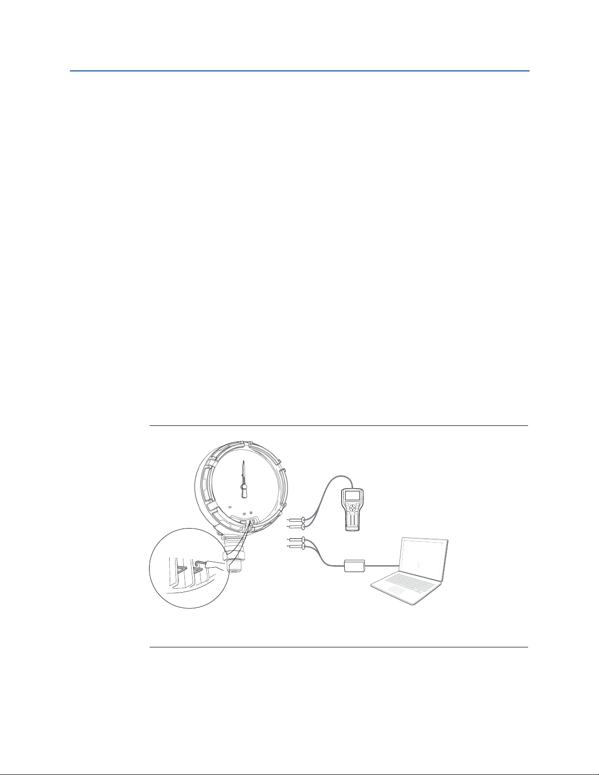
Field Communicator connections
Reference Manual
00809-0100-4045, Rev AB
The device needs to be on in order for the Field Communicator to interface with the
Rosemount Wireless Pressure Gauge. The Field Communicator connection is located to the
right of the ON/OFF switch. To communicate with the device, connect the Field
Communicator to connections labeled “COMM”. Field communication with this device
requires a HART-based tool using the correct Rosemount Wireless Pressure Gauge device
driver (DD). Refer to Figure 2-1 for instructions on connecting the Field Communicator to
the device.
Figure 2-1. Connect to Device
A
123
645
8709
B
A. Field Communicator
B. HART modem
C. AMS Wireless Configurator
C
6
Hardware Installation

Reference Manual
00809-0100-4045, Rev AB
2.3.2 Installation
Measurement performance depends upon proper installation of the device and impulse
piping. Mount the device close to the process and use a minimum of piping to achieve best
performance. Also, consider the need for easy access, personnel safety, and a suitable
device environment. Install the device to minimize vibration, shock, and temperature
fluctuation.
2.3.3 Mechanical
Location
When choosing an installation location and position, take into account the direction of the
device for future access to the COMM connections and readability of the analog display.
Electronics cover
The electronics cover is tightened so that polymer contacts polymer. When removing the
electronics cover, ensure that there is no damage done to the o-ring. If damaged replace
before reattaching cover, ensuring polymer contacts polymer (i.e. no O-ring visible).
Hardware Installation
March 2016
2.3.4 Electrical
Battery
The Rosemount Wireless Pressure Gauge is self-powered. The battery contains
approximately five grams of lithium. Under normal conditions, the battery materials are
self-contained and are not reactive as the as the battery is maintained inside the enclosure
of the device. Care should be taken to prevent thermal, electrical, or mechanical damage.
Contacts should be protected to prevent premature discharge.
Use caution when handling the battery, it may be damaged if dropped.
The battery should be stored in a clean dry area, For maximum battery life, storage
temperature should not exceed 86 °F (30 °C).
2.3.5 Environmental
Verify the operating atmosphere of the device is consistent with the appropriate hazardous
locations certifications.
Temperature effects
The device will operate within specifications for ambient temperatures as outlined on
page 42 in the specifications section. Heat from the process is transferred to the device
housing. If the process temperature is high, the ambient temperature will need to be lower
to account for heat transferred to the device housing. See Temperature limits for process
temperature derating.
Hardware Installation
7
Hardware Installation
OR
March 2016
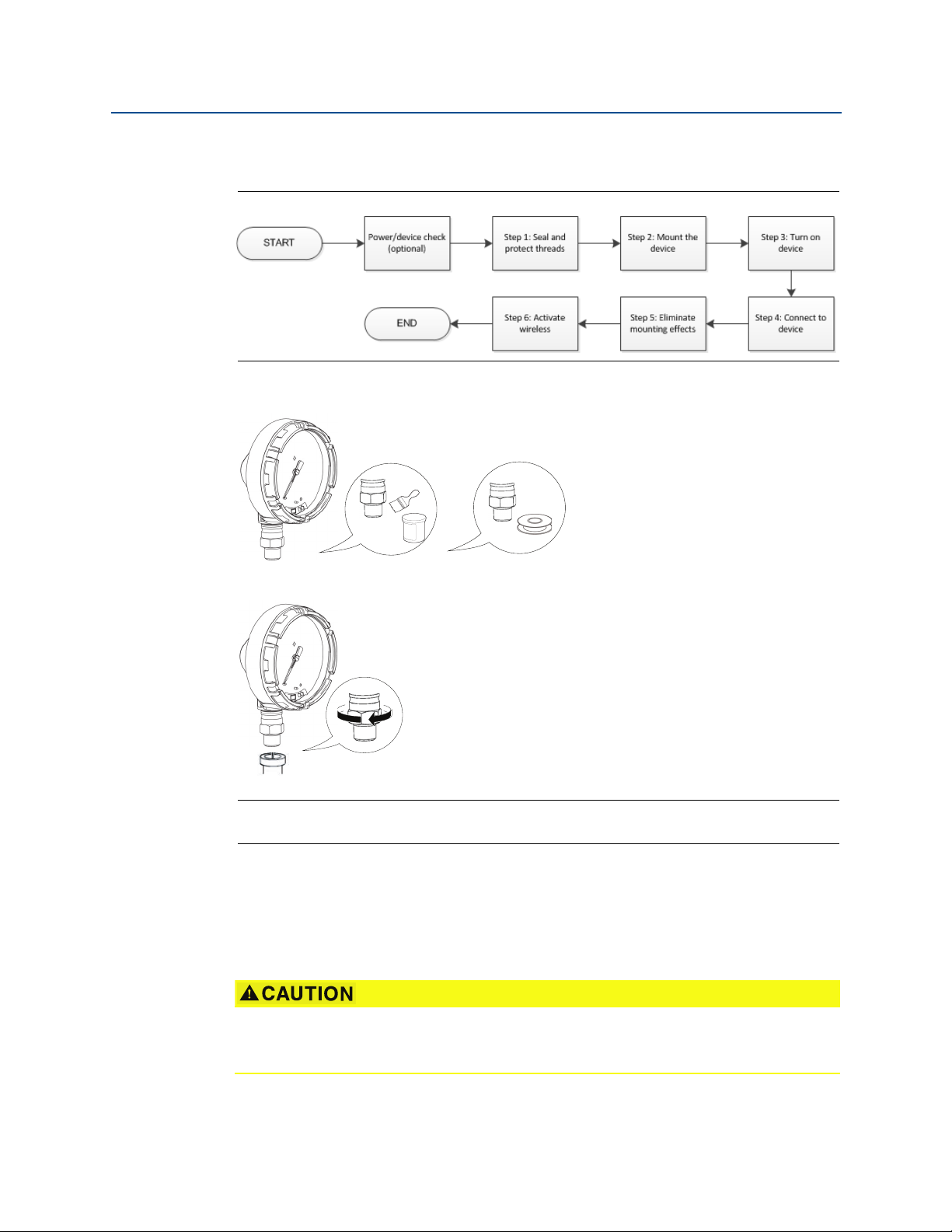
2.4 Installation procedure
Figure 2-2. Installation Flowchart
2.4.1 Seal and protect threads
Reference Manual
00809-0100-4045, Rev AB
2.4.2 Mount device
Note
Use wrench on flats, not on housing.
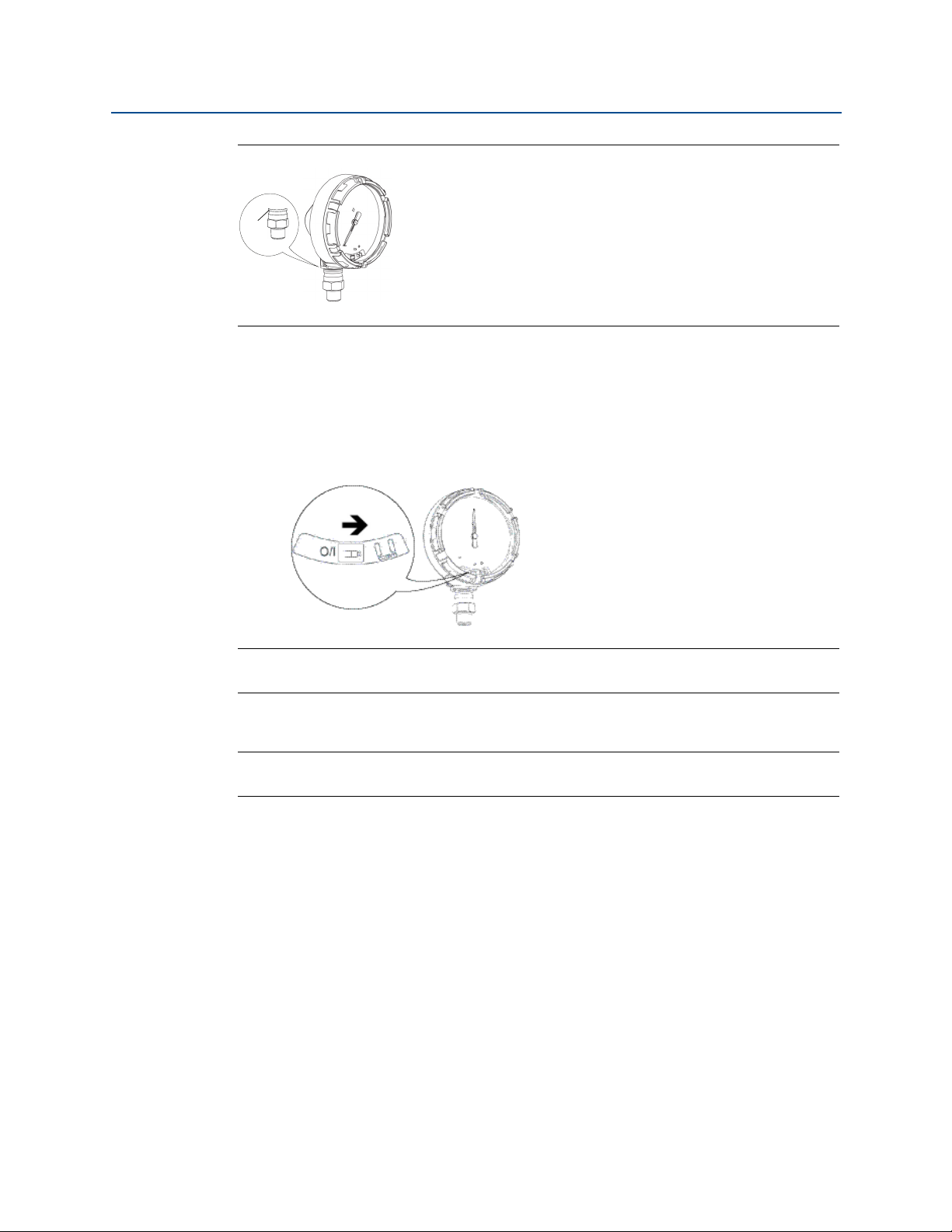
Mounting orientation
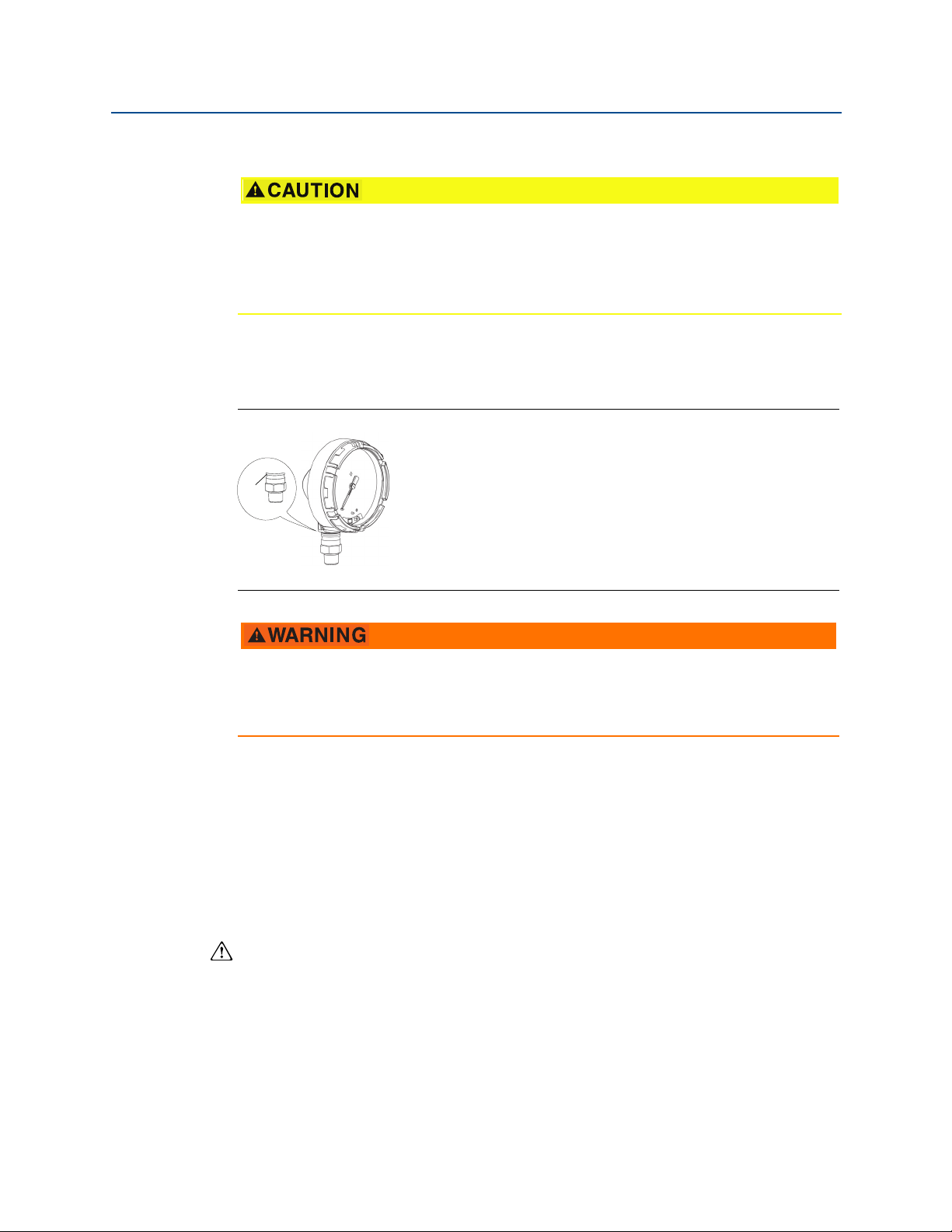
The low side pressure port (atmospheric reference) on the process pressure gauge is
located in the neck of the device behind the housing. The vent path is between the housing
and sensor. (See Figure 2-3.)
Keep the vent path free of any obstruction, including but not limited to paint, dust, and
lubrication by mounting the device so the process can drain away.
8
Hardware Installation
Reference Manual
A
00809-0100-4045, Rev AB
Figure 2-3. Low Side Pressure Port
A. Low side pressure port (atmospheric reference)
2.4.3 Turn on device
Check to ensure the device and battery are working properly.
1. Twist the cover counterclockwise to remove it.
2. Slide the OFF/ON switch to the ON position to initiate the power sequence.
Hardware Installation
March 2016
Note
During the power sequence, the dial tests full range of motion and LED flashes amber.
3. Once the power sequence ends, verify the LED flashes green.
Note
The LED may display several colors; see Table 4-2 on page 33 for device statuses.
2.5 Impulse piping considerations
2.5.1 Best practices
The piping between the process and the device must accurately transfer the pressure to
obtain accurate measurements. There are five possible sources of error: leaks, friction loss
(particularly if purging is used), trapped gas in a liquid line, liquid in a gas line, and density
variations between the legs.
Hardware Installation
9

Hardware Installation
March 2016
The best location for the device in relation to the process pipe depends on the process itself.
Use the following guidelines to determine device location and placement of impulse piping:
Keep impulse piping as short as possible.
For liquid service, slope the impulse piping at least 1 inch per foot (8 cm per m)
For gas service, slope the impulse piping at least 1 inch per foot (8 cm per m)
Avoid high points in liquid lines and low points in gas lines.
Make sure both impulse legs are the same temperature.
Use impulse piping large enough to avoid friction effects and blockage.
Vent all gas from liquid piping legs.
When using a sealing fluid, fill both piping legs to the same level.
When purging, make the purge connection close to the process taps and purge
Keep corrosive or hot (above 250 °F [121 °C]) process material out of direct contact
Prevent sediment deposits in the impulse piping.
Reference Manual
00809-0100-4045, Rev AB
upward from the device toward the process connection.
downward from the device toward the process connection.
through equal lengths of the same size pipe. Avoid purging through the device.
with the sensor module and flanges.
Keep the liquid head balanced on both legs of the impulse piping.
Avoid conditions that might allow process fluid to freeze within the process flange.
2.5.2 Mounting requirements
Liquid flow measurement
Place taps to the side of the line to prevent sediment deposits on the process
isolators.
Mount the device beside or below the taps so gases vent into the process line.
Mount drain/vent valve upward to allow gases to vent.
Gas flow measurement
Place taps in the top or side of the line.
Mount the device beside or above the taps so to drain liquid into the process line.
Steam flow measurement
Place taps to the side of the line.
Mount the device below the taps to ensure that impulse piping will remain filled
with condensate.
Fill impulse lines with water to prevent steam from contacting the device directly
and to ensure accurate measurement start-up.
10
Note
For steam or other elevated temperature services, it is important that temperatures do not
exceed 250 °F (121 °C) for devices with silicone fill. For vacuum service, these temperature
limits are reduced to 220 °F (104 °C) for silicone fill.
Hardware Installation
Reference Manual
A
00809-0100-4045, Rev AB
2.6 Process connection
Interfering or blocking the atmospheric reference port will cause the device to output
erroneous pressure values.
Keep the vent path free of any obstruction, including but not limited to paint, dust, and
lubrication by mounting the device so the process can drain away.
The low side pressure port (atmospheric reference) on the process pressure gauge is
located in the neck of the device behind the housing. The vent path is between the housing
and sensor. (See Figure 2-3.)
Figure 2-4. Low Side Pressure Port
Hardware Installation
March 2016
A. Low side pressure port (atmospheric reference)
a
Do not apply torque directly to the sensor module. Rotation between the sensor
module and the process connection can damage the electronics. To avoid damage,
apply torque only to the hex-shaped process connection.
2.7 Rosemount manifolds
The Rosemount 306 Integral Manifold mounts directly to the device. The manifold is used
with this device to provide block-and-bleed valve capabilities of up to 4000 psi (275 bar).
2.7.1 Installation procedure
The Rosemount 306 Manifold is for use only with a Rosemount Wireless Pressure Gauge.
Assemble the Rosemount 306 Manifold to the device with a thread sealant.
1. Place device into holding fixture.
2. Apply appropriate thread paste or tape to threaded instrument end of the
manifold.
3. Count total threads on the manifold before starting assembly.
4. Start turning the manifold by hand into the process connection on the device.
Hardware Installation
11
Hardware Installation
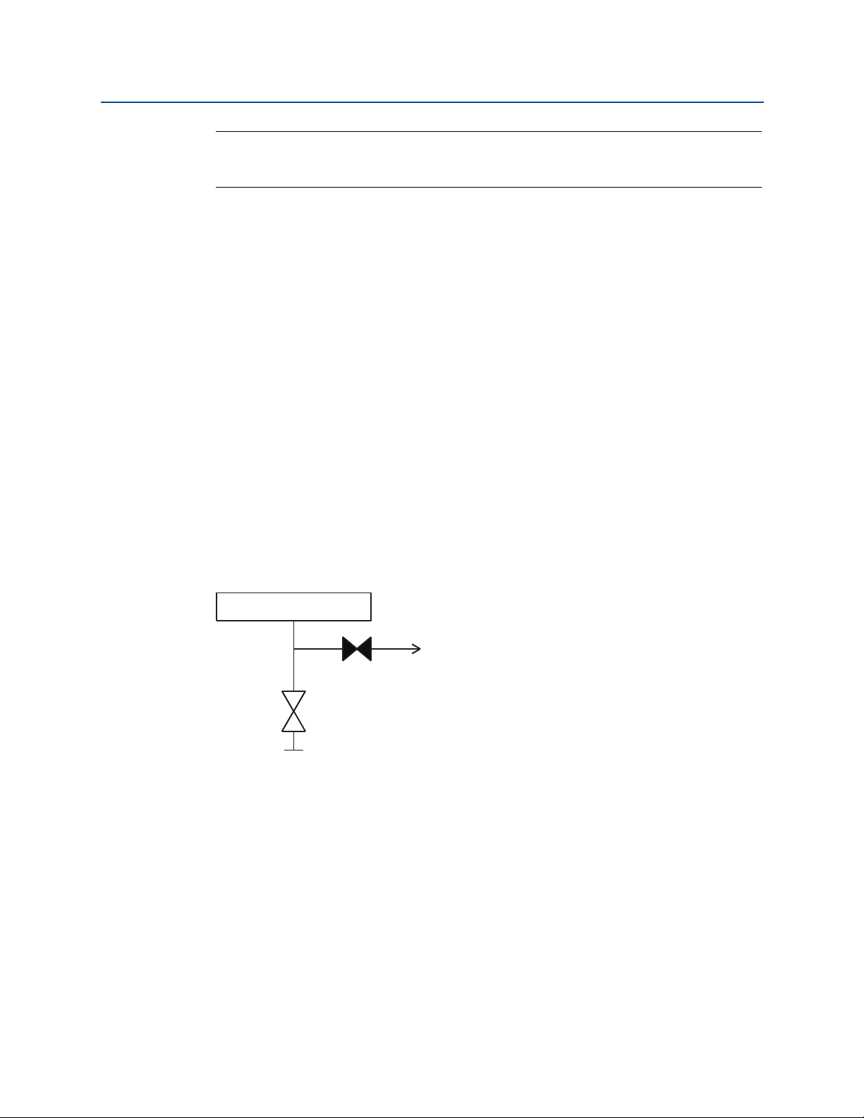
Device
Test/vent
(closed)
Isolate
Process
(open)
March 2016
Note
If using thread tape, be sure the thread tape does not strip when the manifold assembly is
started.
5. Wrench tighten manifold into process connection (minimum toque value is
425 in-lbs).
6. Count how many threads are still showing (minimum engagement is 3
revolutions).
7. Subtract the number of threads showing (after tightening) from the total threads
to calculate the revolutions engaged. Further tighten until a minimum of 3
rotations is achieved.
8. For block and bleed manifold, verify the bleed screw is installed and tightened. For
2-valve manifold, verify the vent plug is installed and tightened.
9. Leak-check assembly to maximum pressure range of device.
2.7.2 Manifold operation
Reference Manual
00809-0100-4045, Rev AB
2-Valve and Block and Bleed Style Manifolds
Isolating the device
In normal operation the Isolate (block) valve between the process port and device will be
open and the Test/Vent valve will be closed. On a block and bleed style manifold, a single
block valve provides device isolation and a bleed screw provides drain/vent capabilities.
12
Hardware Installation
Reference Manual
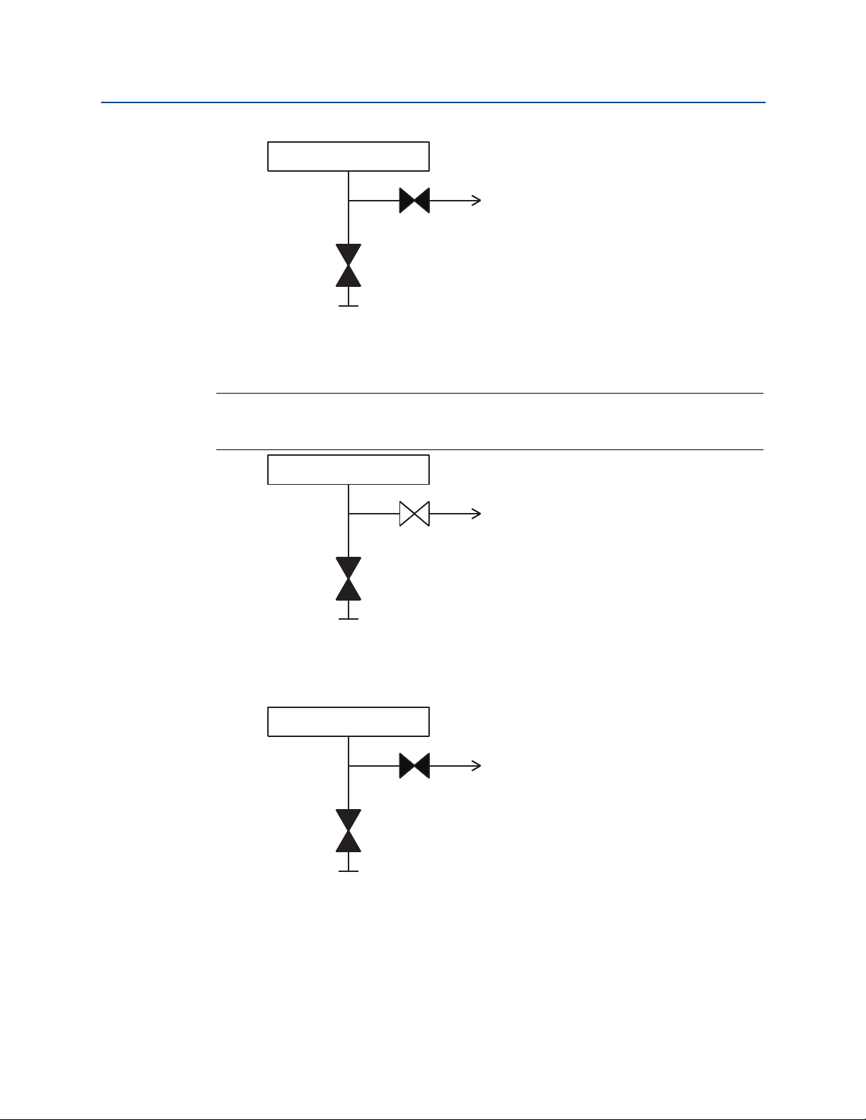
Device
Test/vent
(closed)
Isolate
Process
(closed)
Device
Test/vent
(open)
Isolate
Process
(closed)
Device
Test/vent
(closed)
Isolate
Process
(closed)
00809-0100-4045, Rev AB
1. To isolate the device, close the isolate valve.
2. To bring the device to atmospheric pressure, open the vent valve or bleed screw.
Note:
1
A
/4-in. male NPT pipe plug may be installed in the test/vent port and will need to be
removed with a wrench in order to vent the manifold properly.
Hardware Installation
March 2016
Hardware Installation
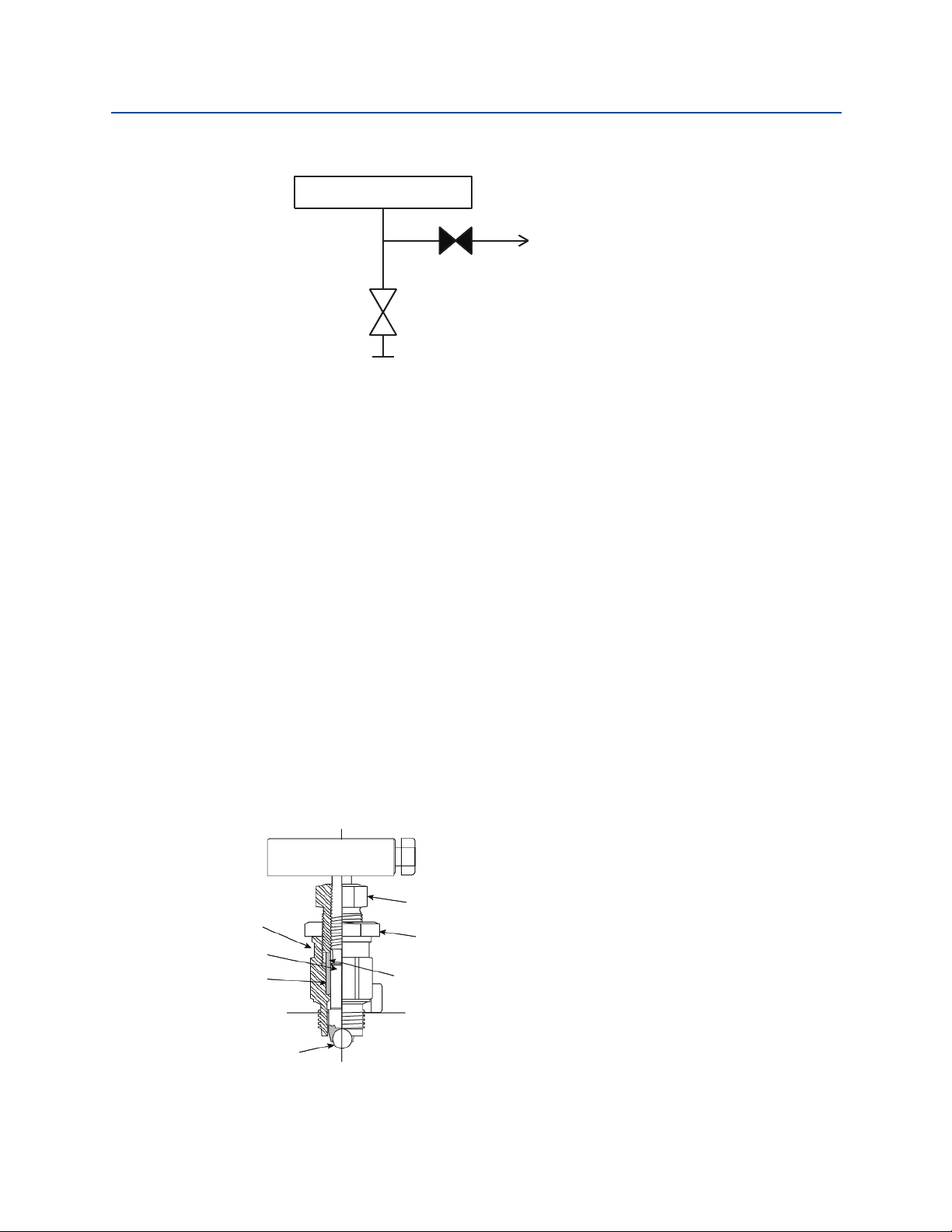
3. After venting to atmosphere, perform any required calibration and then close the
test/vent valve or replace the bleed screw.
13
Hardware Installation
Device
Test/vent
(closed)
Isolate
Process
(open)
A
B
C
D
E
F
G
March 2016
4. Open the Isolate (block) valve to return the device to service.
Adjusting valve packing
Over time, the packing material inside a Rosemount manifold may require adjustment in
order to continue to provide proper pressure retention. Not all Rosemount manifolds have
this adjustment capability. The Rosemount manifold model number will indicate what type
of stem seal or packing material has been used.
Reference Manual
00809-0100-4045, Rev AB
The following steps are provided as a procedure to adjust valve packing.
1. Remove all pressure from device.
2. Loosen manifold valve jam nut.
3. Tighten manifold valve packing adjuster nut
1
/4 turn.
4. Tighten manifold valve jam nut.
5. Re-apply pressure and check for leaks.
6. Above steps can be repeated, if necessary.
If the above procedure does not result in proper pressure retention, the complete manifold
should be replaced.
14
A. Bonnet
B. Stem
C. Packing
D. Ball seat
E. Packing adjuster
F. J am nut
G. Packing follower
Hardware Installation

Reference Manual
00809-0100-4045, Rev AB
Section 3 Configuration
Overview . . . . . . . . . . . . . . . . . . . . . . . . . . . . . . . . . . . . . . . . . . . . . . . . . . . . . . . . . . . . . . . . page 15
Safety messages . . . . . . . . . . . . . . . . . . . . . . . . . . . . . . . . . . . . . . . . . . . . . . . . . . . . . . . . . . page 15
System readiness . . . . . . . . . . . . . . . . . . . . . . . . . . . . . . . . . . . . . . . . . . . . . . . . . . . . . . . . . page 16
Configuration basics . . . . . . . . . . . . . . . . . . . . . . . . . . . . . . . . . . . . . . . . . . . . . . . . . . . . . . page 16
Basic gauge setup . . . . . . . . . . . . . . . . . . . . . . . . . . . . . . . . . . . . . . . . . . . . . . . . . . . . . . . . . page 17
Configuration verification . . . . . . . . . . . . . . . . . . . . . . . . . . . . . . . . . . . . . . . . . . . . . . . . . . page 18
Advanced device parameter setup . . . . . . . . . . . . . . . . . . . . . . . . . . . . . . . . . . . . . . . . . . page 20
Notifications and service . . . . . . . . . . . . . . . . . . . . . . . . . . . . . . . . . . . . . . . . . . . . . . . . . . . page 21
3.1 Overview
This section contains information on commissioning and tasks.
Configuration
March 2016
Field Communicator and AMS
configuration functions.
Full Field Communicator menu trees are available in Appendix C: Field Communicator Menu
Tr ee s.
™
3.2 Safety messages
Procedures and instructions in this section may require special precautions to ensure the
safety of the personnel performing the operation. Information that raises potential safety
issues is indicated with a warning symbol ( ). Refer to the following safety messages
before performing an operation preceded by this symbol.
Explosions could result in death or serious injury.
Installation of this device in an explosive environment must be in accordance with
the appropriate local, national, and international standards, codes, and practices.
Review the approvals section of the Wireless Pressure Gauge Reference Manual
for any restrictions associated with a safe installation.
Before connecting a Field Communicator in an explosive atmosphere, make sure
the instruments are installed in accordance with intrinsically safe or
non-incendive field wiring practices.
Verify the operating atmosphere of the device is consistent with the appropriate
hazardous locations certifications.
Device Manager Instructions are given to perform
Configuration
15
 Loading...