

Page 1
Instruction Manual
LIQ-MAN-56, Rev B
July 2017
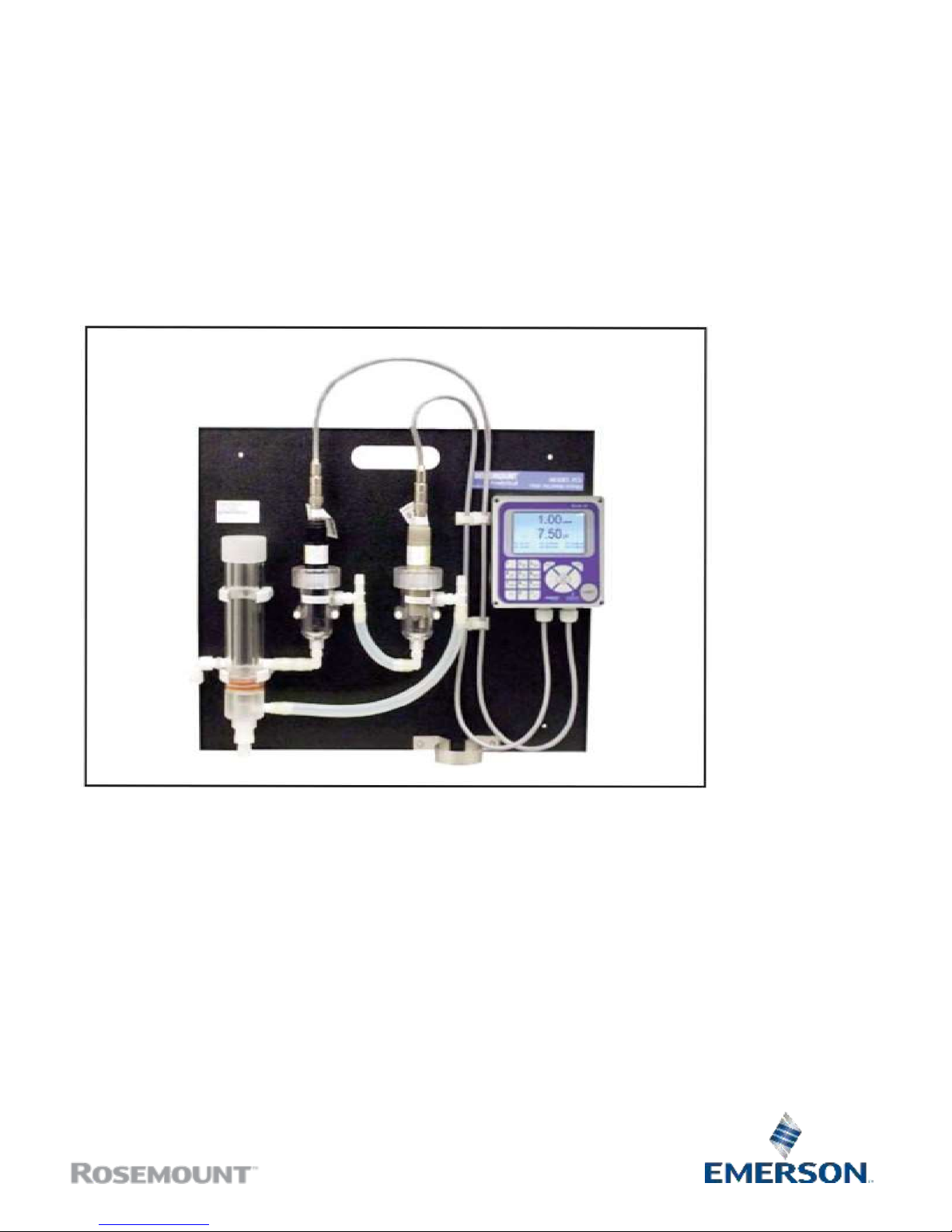
FCL with 56
Transmitter
Page 2
ESSENTIAL INSTRUCTIONS
READ THIS PAGE BEFORE PROCEEDING!
Your purchase from Rosemount, Inc. has resulted in
one of the finest instruments available for your
particular application. These instruments have been
designed, and tested to meet many national and
international standards. Experience indicates that
its performance is directly related to the quality of
the installation and knowledge of the user in operating and maintaining the instrument. To ensure
their continued operation to the design specifications, personnel should read this manual thoroughly
before proceeding with installation, commissioning,
operation, and maintenance of this instrument. If
this equipment is used in a manner not specified by
the manufacturer, the protection provided by it
against hazards may be impaired.
• Failure to follow the proper instructions may
cause any one of the following situations to
occur: Loss of life; personal injury; property damage; damage to this instrument; and warranty
invalidation.
• Ensure that you have received the correct model
and options from your purchase order. Verify that
this manual covers your model and options. If
not, call 1-800-854-8257 or 949-757-8500 to
request correct manual.
• For clarification of instructions, contact your
Rosemount representative.
• Follow all warnings, cautions, and instructions
marked on and supplied with the product.
• Use only qualified personnel to install, operate,
update, program and maintain the product.
• Educate your personnel in the proper installation,
operation, and maintenance of the product.
• Install equipment as specified in the Installation
section of this manual. Follow appropriate local
and national codes. Only connect the product to
electrical and pressure sources specified in this
manual.
• Use only factory documented components for
repair. Tampering or unauthorized substitution of
parts and procedures can affect the performance
and cause unsafe operation of your process.
• All equipment doors must be closed and protective covers must be in place unless qualified personnel are performing maintenance.
• If this equipment is used in a manner not specified by the manufacturer, the protection provided
by it against hazards may be impaired.
W
ARNING
RISK OF ELECTRICAL SHOCK
Equipment protected throughout by double insulation.
• Installation of cable connections and servicing of this product
require access to shock hazard voltage levels.
• Main power and relay contacts wired to separate power
source must be disconnected before servicing.
• Do not operate or energize instrument with case open!
• Signal wiring connected in this box must be rated at least
240 V.
• Non-metallic cable strain reliefs do not provide grounding
between conduit connections! Use grounding type bushings
and jumper wires.
• Unused cable conduit entries must be securely sealed by
non-flammable closures to provide enclosure integrity in
compliance with personal safety and environmental protection
requirements. Unused conduit openings must be sealed with
NEMA 4X or IP65 conduit plugs to maintain the ingress
protection rating (NEMA 4X).
• Electrical installation must be in accordance with the National
Electrical Code (ANSI/NFPA-70) and/or any other applicable
national or local codes.
• Operate only with front and rear panels fastened and in place
over terminal area.
• Safety and performance require that this instrument be
connected and properly grounded through a three-wire
power source.
• Proper relay use and configuration is the responsibility of the
user.
CAUTION
This product generates, uses, and can radiate radio frequency
energy and thus can cause radio communication interference.
Improper installation, or operation, may increase such interference. As temporarily permitted by regulation, this unit has not
been tested for compliance within the limits of Class A computing devices, pursuant to Subpart J of Part 15, of FCC Rules,
which are designed to provide reasonable protection against
such interference. Operation of this equipment in a residential
area may cause interference, in which case the user at his own
expense, will be required to take whatever measures may be
required to correct the interference.
W
ARNING
This product is not intended for use in th e light industrial,
residential or commercial environments per the instrument’s
certification to EN50081-2.
Page 3

QUICK START
GUIDE
FOR FCL
TRANSMITTER
1. Refer to Section 2.0 for installation instructions and Section 3.0 for wiring instructions.
2. Once connections are secure and verified, apply power to the transmitter.
3. When the transmitter is powered up for the first time Quick Start screens appear.
4. The first quick start screen has two control boxes, one for language and the other for temperature units.
a. The cursor, shown by dark blue backlighting, will be on the language control box. To change the language,
press the ENTER/MENU key. A list of available languages, shown two at a time, will appear. Using the up
and down keys, scroll (see section 4.2) to display the choices. Press ENTER/MENU to select the desired
language. Press the down key to move to the cursor to the temperature control box. To change units,
press ENTER/MENU and scroll to either °F or °C. Press ENTER/MENU to store the selection.
b. To move to the next screen, use the navigation keys to move the cursor to NEXT and press
ENTER/MENU.
5. The next screen lists navigation rules. Press ENTER/MENU for the next screen.
6. The next step is to configure sensor 1. Sensor 1 is the free chlorine sensor. The screen has three control boxes.
a. For measurement choose free chlorine. Do not choose pH-independent free chlorine.
b. Choose the desired units, mg/L or ppm
c. If you have an FCL-02 (with pH sensor), the third control box lets you choose between live/continuous
or manual pH correction. If you choose live/continuous (recommended), the transmitter will use the pH
measured by the pH sensor to correct the chlorine reading for pH changes. If you choose manual (not
recommended), a fourth control box will appear to let you enter the manual pH, and the transmitter
will use the entered value to correct the chlorine reading.
d. If you have an FCL-01 (no pH sensor), enter the pH of the process liquid in the third control box.
e. Move the cursor to NEXT and press ENTER/MENU. If you have an FCL-01, the display will change to
show some basic keypad operation guidelines. Press ENTER/MENU to show the main display. If you
have an FCL-02, go to step 7.
7. The next step is to configure sensor 2. Sensor 2 is the pH sensor. The screen has two control boxes.
a. For measurement choose pH.
b. For pre-amplifier location choose transmitter.
c. Move the cursor to NEXT and press ENTER/MENU. The display will change to show some basic keypad
operation guidelines. Press ENTER/MENU to show the main display.
8. The outputs, alarms, display configuration, and data logging are all assigned to default values. The default value for
data logging is disabled. To change the settings refer to Sections 4.5, 5.0, and 8.0.
Page 4

About This Document
This manual contains instructions for installation and operation of the FCL-56
The following list provides notes concerning all revisions of this document.
Rev. Level
Date
Notes
5/11
This is the initial release of the product manual. The manual has been
reformatted to reflect the Emerson documentation style and updated to
reflect any changes in the product offering.
A 03/12
Update addresses - mail and web
B
07/17
Changed instances of analyzer to transmitter. Replaced Rosemount
Analytical with Rosemount. Replaced Emerson Process Management
with Emerson. Updated addresses and logos and reformatted back
page.
Page 5

MODEL FCL–56
TABLE OF CONTENTS
FCL-56
TABLE OF CONTENTS
Section Title Page
1.0 DESCRIPTION AND SPECIFICATIONS ................................................................ 1
1.1 Applications ............................................................................................................. 1
1.2 Features ................................................................................................................... 1
1.3 Specifications - General ........................................................................................... 2
1.4 Specifications - Sensor ............................................................................................ 2
1.5 Specifications - Transmitter .......................................................................................... 2
1.6 Ordering Information ................................................................................................ 3
2.0
INSTALLATION
.......................................................................................................
5
2.1
Unpacking and Inspection........................................................................................
5
2.2
Inst
allation ................................................................................................................
6
3.0 WIRING....................................................................................................................
9
3.1
Power, Alarm, and Output Wiring .............................................................................
9
3.2
Sensor Wiring .........................................................................................................
10
4.0 DISPLAY AND
OPERATION
...................................................................................
13
4.1
Display .....................................................................................................................
13
4.2
Keypad .....................................................................................................................
13
4.3
Operation .................................................................................................................
14
4.4
Hold..........................................................................................................................
16
4.5
Main Display ............................................................................................................
17
4.6
Security ....................................................................................................................
18
5.0 PROGRAMMING THE TRANSMITTER
19
5.1
Entering the Program Menus ...................................................................................
19
5.2
Outputs ....................................................................................................................
19
5.3
Relays ......................................................................................................................
20
5.4
Measurement ...........................................................................................................
22
5.5 Temperature .............................................................................................................
22
5.6
pH Diagnostic Setup ................................................................................................
23
5.7
Configuring Security Settings...................................................................................
23
5.8
Restoring Default Settings .......................................................................................
23
6.0 CALIBRATION ........................................................................................................
25
6.1
Introduction ..............................................................................................................
25
6.2
Entering the Calibration Menus................................................................................
25
6.3
Calibrating Temperature...........................................................................................
25
6.4
Calibrating the Free Chlorine Sensor ......................................................................
26
6.5
Calibrating the pH Sensor .......................................................................................
27
6.6
Calibrating the Analog Outputs ................................................................................
27
6.7
Reset........................................................................................................................
27
i
Page 6

MODEL FCL–56
TABLE OF CONTENTS
TABLE OF CONTENTS CONT’D
Section Title Page
7.0 DIGITAL COMMUNICATIONS ............................................................................... 29
8.0 DATA AND EVENT LOGGING AND
RETRIEVAL
.................................................. 31
8.1 Overview .................................................................................................................. 31
8.2 Configuration............................................................................................................ 31
8.3 Downloading Data and Events................................................................................. 32
8.4 Viewing Events......................................................................................................... 32
8.5 Date and Time.......................................................................................................... 32
9.0 GRAPHICAL DISPLAY .......................................................................................... 33
9.1 Overview .................................................................................................................. 33
9.2 Configuration............................................................................................................ 33
10.0 MAINTENANCE ..................................................................................................... 35
10.1 Transmitter ................................................................................................................... 35
10.2 Chlorine Sensor ....................................................................................................... 36
10.3 pH Sensor ................................................................................................................ 37
10.4 Constant Head Flow Controller ................................................................................ 38
11.0 TROUBLESHOOTING ........................................................................................... 41
11.1 Overview .................................................................................................................. 41
11.2 Reading and Troubleshooting Fault and Warning Messages .................................. 41
11.3 Sensor Diagnostics .................................................................................................. 41
11.4 Troubleshooting Calibration Problems ..................................................................... 42
11.5 Other Troubleshooting – Chlorine ............................................................................ 42
11.6 Other Troubleshooting – pH ..................................................................................... 43
11.7 Other Troubleshooting – General............................................................................. 45
11.8 Simulating Inputs – Chlorine .................................................................................... 45
11.9 Simulating Inputs – pH ............................................................................................. 46
11.10 Simulating Inputs – Temperature ............................................................................. 47
LIST OF TABLES
Number Title Page
1.6 Ordering Information ............................................................................................... 3
1.6 Component Parts ..................................................................................................... 3
1.6 Accessories .............................................................................................................. 3
3.2 Sensor Wiring ........................................................................................................... 10
4.1 Display Abbreviations ............................................................................................... 13
10.1 Transmitter ................................................................................................................... 35
10.2 Spare Parts............................................................................................................... 37
10.3 Replacement Parts FCL-01 ...................................................................................... 39
10.4 Replacement Parts FCL-02 ...................................................................................... 40
11.5 Troubleshooting – Chlorine ...................................................................................... 42
ii
Page 7

MODEL FCL–56
TABLE OF CONTENTS
LIST OF TABLES CONT’D
11.6
Other Troubleshooting – pH .....................................................................................
43
11.7
Other Troubleshooting – General .............................................................................
45
11.9
Simulating Inputs – pH .............................................................................................
46
11.10
Simulating Inputs Temperature.................................................................................
47
LIST OF
FIGURES
Number Title Page
2-1 Model FCL-01 .................................................................................................... 7
2-2 Model FCL-02 .................................................................................................... 7
3-1 Analog Output Connections ..................................................................................... 9
3-2 Alarm Relay Connections ......................................................................................... 10
3-3 Wiring Diagram for Free Chlorine Sensor ............................................................... 11
3-4 Wiring Diagram for 399VP-09 pH Sensor ............................................................... 11
3-5 Wiring Diagram for 3900VP-10 pH sensor (gray cable) .......................................... 11
3-6 Wiring Diagram for 3900VP-10 pH sensor (blue cable) .......................................... 11
4-1 Main Display .................................................................................................... 13
4-2 Transmitter Keypad .................................................................................................... 13
5-1 Menu Tree for Outputs Sub Menu ........................................................................... 19
5-2 Menu Tree for Relays Sub Menu ............................................................................. 20
5-3 Menu Tree for Measurements Sub Menu ................................................................. 22
5-4 Menu Tree for Temperature Sub Menu .................................................................... 22
5-5 Menu Tree for pH Diagnostic Sub Menu .................................................................. 23
5-6 Menu Tree for Security Sub Menu............................................................................ 23
10-1 Chlorine Sensor Parts .............................................................................................. 37
10-2 Replacement Parts for the Flow Controller Assembly used in Model FCL-01.......... 39
10-3 Replacement Parts for the Flow Controller Assembly used in Model FCL-02.......... 40
11-1 Simulating Chlorine .................................................................................................. 45
11-2 Simulating pH Inputs ................................................................................................ 46
11-3 Three-Wire RTD Configuration................................................................................. 47
11-4 Simulating RTD Inputs.............................................................................................. 47
iii
Page 8

MODEL FCL– 56
This page left blank
intentionally
iv
Page 9

MODEL FCL– 56
SECTION 1.0
DESCRIPTION AND SPECIFICATIONS
SECTION
1.0.
DESCRIPTION AND
SPECIFICATIONS
• COMPLETE SYSTEM INCLUDES sensor, connecting cable, transmitter, and flow controller
• CONTINUOUS pH CORRECTION eliminates expensive and messy reagents and trouble-
some sample conditioning systems
• MEASURES FREE CHLORINE IN SAMPLES having pH as high as 9.5
1
• VARIOPOL QUICK-DISCONNECT FITTINGS make replacing sensors easy
• FEATURE-PACKED TRANSMITTER: four outputs, four fully-programmable relays, data
logger, and large full color display including graphics.
1
In some cases, the sensor can be used in samples having pH as great as 10.0. Consult the factory.
1.1 APPLICATIONS
The FCL free chlorine system is intended for the determination of free chlorine in fresh water. Unlike free
chlorine transmitters from other manufacturers, the
FCL does not use expensive sample conditioning
systems or messy reagents to control pH. Instead, the
transmitter automatically compensates for changes in
the pH of the sample. The FCL is not intended for the
determi- nation of total chlorine or combined
chlorine (like monochloramine). Nor, can the FCL be
used for the determination of chlorine in seawater.
1.2 FEATURES
The FCL uses a membrane-covered amperometric
sensor. A polarizing voltage applied to a platinum
cathode behind the membrane reduces the chlorine
diffusing through the membrane and keeps the concentration of chlorine in the sensor equal to zero. The
current generated by the cathode reaction is proportional to the rate of diffusion of chlorine through the
membrane. Because the concentration of chlorine in
the sensor is zero, th e diffusion rate and the current
are proportional to the concentration of chlorine in the
sample.
All amperometric free chlorine sensors respond to
changes in pH. Although free chlorine is a mixture of
hypochlorous acid and hypochlorite ion, hypochlorous
acid alone is responsible for the sensor current.
Because the relative amounts of hypochlorous acid
and hypochlorite ion depend on pH, a pH change will
cause the current and the apparent free chlorine
concentration to change, even though the true concentration remained constant. Most manufacturers
solve the pH-dependence problem by treating the
sample with acid, which lowers the pH and converts
hypochlorite ion into hypochlorous acid. The FCL
avoids the expense and inconvenience of sample conditioning by measuring the pH and applying a correction to the raw chlorine sensor signal. The correction
is valid between pH 6.0 and 9.5. For samples having
pH between 9.5 and 10.0, consult the factory.
The FCL is available in two options: Model FCL-01
with manual pH correction and Model FCL-02 with
continuous pH correction. Choose the FCL-01 if the
pH varies less than 0. 2 or if pH changes are
predictable or seasonal. Choose the FCL-02 if the pH
varies more than 0.2. To provide the continuous
pH correction, the Model FCL-02 requires a separate
pH sensor.
Maintenance is fast and easy. Replacing a membrane
requires no special tools or fixtures. A screw cap holds
the pre-tensioned membrane in place. Replacing the
electrolyte solution takes only minutes.
The FCL includes the easy-to-use 56 transmitter.
The transmitter features four fully programmable 4-20
mA out- puts and four fully programmable relays. The
large, full color display allows the user to read sample
pH and chlorine concentration at a
glance. A data logger, graphical display, and
HART digital communications are standard.
Valves, rotameters, and pressure regulators to control
sample flow are things of the past with the FCL. A constant head overflow sampler ensures the correct sample flow to each sensor. To eliminate wiring hassles,
quick-disconnect Variopol cable is standard.
Stable free chlorine standards do not exist. The chlorine
sensor must be calibrated using the results of a laboratory test run on a grab sample.
1
Page 10

MODEL FCL– 56
SECTION 1.0
DESCRIPTION AND SPECIFICATIONS
1.3 SPECIFICATIONS — GENERAL
Sample requirements:
Pressure: 3 to 65 psig (122 to 549 kPa abs)
A check valve in the inlet prevents the sensor flow
cells from going dry if sample flow is lost. The check
valve opens at 3 psig (122 kPa abs). If the check
valve is removed, minimum pressure is 1 psig
(108 kpa abs).
Temperature: 32 to 122°F (0 to 50°)
Minimum Flow: 3 gal/hr (11 L/hr)
Maximum flow: 80 gal/hr (303 L/hr); high flow causes
the overflow tube to back up
Sample Conductivity: >50 µS/cm at 25°C
Process connection: 1/4-in OD tubing compression
fitting (can be removed and replaced with barbed
fitting for soft tubing)
Drain connection: 3/4-in barbed fitting. Sample must
drain to open atmosphere.
Wetted parts:
Overflow sampler and flow cell: acrylic, polycarbonate, Kynar®1, nylon, silicone
Chlorine sensor: Noryl®2, Viton®3, wood, silicone,
polyethersulfone, polyester, and platinum
pH sensor (3900VP): stainless steel, glass, Teflon®4,
polyphenylene sulfide, EPDM, and silicone
Response time: <80 sec to 95% of final reading for
inlet sample flow of 3 gph (11 L/hr)
Weight/shipping weight:
Model FCL-01: 10 lb/13 lb (4.5 kg/6.0 kg)
Model FCL-02: 11 lb/14 lb (5.0 kg/6.5 kg)
[rounded to the nearest 1 lb. (0.5 kg)]
1.4 SPECIFICATIONS — SENSOR
Free chlorine range: 0 to 10 ppm as Cl2. For higher
ranges, consult the factory.
pH correction range: 6.0 to 9.5. For samples having
pH between 9.5 and 10.0, consult the factory.
If pH < 6.0, correction is not necessary. For manual
pH correction, choose option -01. For continuous
pH correction choose option -02.
Accuracy: Accuracy depends on the accuracy of the
chemical test used to calibrate the sensor.
Interferences: Monochloramine, permanganate,
peroxides.
Electrolyte volume: 25 mL (approx.)
Electrolyte life: 3 months (approx.); for best results
replace electrolyte monthly.
1.5 SPECIFICATIONS — TRANSMITTER
Case: Polycarbonate
Display: Full color LCD, 3.75 x 2.20 in. (95 x 56 mm);
display can be customized by the user.
Languages: English, French, German, Italian, Spanish,
Portuguese, Chinese, Russian, and Polish.
Ambient Temperature and Humidity: 14 to 140°F (-
10 to 60°C); RH 5 to 95% (non-condensing).
Between 23 and 131°F (-5 to 55°C) there is no visible degradation in display response or performance.
Storage temperature: -4 to 140°F (-20 to 60°C)
Power: 85 to 265 VAC, 47.5 to 65.0 Hz, 20 W
RFI/EMI:
EN-61326
LVD: EN-6101-01
Outputs: Four 4-20 or 0-20 mA isolated current outputs;
assignable to measurement or temperature; fully
scalable; maximum load 550 Ω. HART digital signal
is superimposed on output 1.
Alarms and Timers: Four relays, fully configurable as
a setpoint alarm, interval timer, TPC, bleed and
feed timer, delay timer, date and time timer, and
fault alarm.
Relays: Form C, SPDT, epoxy sealed.
Relay Contact ratings:
5 A at 28 VDC or 300 VAC (resistive)
1/8 HP at 120/240 VAC
Control features: PID control (analog output) and time
proportional control or TPC (relays) are standard.
Data logger: Data automatically stored every 30 seconds
for 30 days; older data removed to make room for
new data. The following data are automatically stored:
Chlorine: date and time, ppm, temperature, raw
sensor current
pH: date and time, pH, temperature, mV, glass
impedance, and reference impedance (if available)
Event logger: Stores up to 300 events with data and
time stamp: faults, warnings, calibration data, calibration results (pass or fail), power on/off cycles, and
hold on/off. Alarm relay activation and deactivation
can also be stored. Older events are automatically
removed to make room for new events.
Data and event downloading: through USB port on
front panel.
Graphical display: Dual graphical display shows
measurement data on the y-axis and time on the
x-axis. Y-axis is fully assignable and scalable. X-
axis can be set to one hour, one day, seven days,
or 30 days.
Digital communications: HART digital communica-
tions is standard.
1
Kynar is a registered trademark of Elf Atochem North America.
2
Noryl is a registered trademark of General Electric.
3
Viton is a registered trademark of E.I. duPont de Nemours & Co.
4
Teflon is a registered trademark of E.I. duPont de Nemours & Co.
2
Page 11
MODEL FCL– 56
SECTION 1.0
DESCRIPTION AND SPECIFICATIONS
1.6 ORDERING INFORMATION
Model FCL Free Chlorine Measuring System. The FCL is a complete system for the determination of free chlo-
rine in aqueous samples. It consists of the sensor(s), transmitter, and constant head overflow device to control
sam- ple flow. All components are mounted on a backplate. Model option -02 includes a pH sensor for continuous,
automatic pH correction. Three replacement membranes and a 4-oz. bottle of electrolyte solution are shipped
with the chlorine sensor.
FCL FREE CHLORINE MEASURING SYSTEM
CODE
pH CORRECTION (required selection)
01
Without pH sensor
02
With pH sensor
CODE
pH CORRECTION (required selection)
240
56-03-24-38-HT, 85–265 VAC, 47.5/65.0 Hz, chlorine only (option -01 only)
241
56-03-24-32-HT, 85–265 VAC, 47.5/65.0 Hz, chlorine and pH (option -02 only)
FCL-02 -241 EXAMPLE
COMPONENT PARTS
TRANSMITTER
DESCRIPTION
56-03-24-38-HT
56-03-24-38-HT, 85–265 VAC, 47.5/65.0 Hz, chlorine only
56-03-24-32-HT
56-03-24-32-HT, 85–265 VAC, 47.5/65.0 Hz, chlorine and pH
SENSOR MODEL
DESCRIPTION
499ACL-01-54-VP
Free chlorine sensor with Variopol connector
3900VP-02-10
pH sensor with Variopol connector
SENSOR CABLE
DESCRIPTION
23747-04
Interconnecting cable, Variopol for 499ACL sensor, 4 ft
23645-08
Interconnecting cable, Variopol for 3900VP sensor, 4 ft
ACCESSORIES
PART #
DESCRIPTION
9240048-00
Tag, stainless steel (specify marking)
3
Page 12

MODEL FCL– 56
SECTION 1.0
DESCRIPTION AND SPECIFICATIONS
This page left blank
intentionally
4
Page 13

MODEL FCL–56
SECTION 2.0
INST
ALLA
TION
SECTION
2.0.
INSTALLATION
2.1 UNPACKING AND INSPECTION
Inspect the shipping container. If it is damaged, contact the shipper immediately for instructions. Save the box. If
there is no apparent damage, unpack the container. Be sure all items shown on the packing list are present. If items
are missing, notify Rosemount immediately.
2.1.1 MODEL FCL-01 (free chlorine without continuous pH correction)
Model FCL-01 consists of the following items mounted on a back plate.
1. Model 56-03-24-38-HT transmitter with sensor cable
attached.
2. Constant head flow controller with flow cell for chlorine sensor.
The free chlorine sensor (Model 499ACL-01-54-VP), three membrane assemblies, and a bottle of electrolyte solution
are in a separate package.
2.1.2 MODEL FCL-02 (free chlorine with continuous pH correction)
Model FCL-02 consists of the following items mounted on a back plate.
1. Model 56-03-24-32-HT transmitter with sensor cables
attached.
2. Constant head flow controller with flow cells for pH and chlorine sensors.
3. Ring clamp to hold pH buffer solution during calibration.
The free chlorine sensor (Model 499ACL-01-54-VP), three membrane assemblies, and a bottle of electrolyte solution,
and the Model 3900VP-02-10 sensor, which replaces the Model 399VP-09 sensor, are in separate packages.
5
Page 14
MODEL FCL–56
SECTION 2.0
INST
ALLA
TION
2.2 INSTALLATION
2.2.1 General Information
1. Although the system is suitable for outdoor use, do not install it in direct sunlight or in areas of extreme
temperature.
CAUTION
The FCL free chlorine transmitter is NOT suitabl e
for use in hazardous areas.
2. To keep the transmitter enclosure watertight, install plugs (provided) in the unused cable
openings.
3. Install the system in an area where vibrations and electromagnetic and radio frequency interference are minimized or absent.
4. Be sure there is easy access to the transmitter and
sensors.
2.2.2 Sample Requirements
Be sure the sample meets the following requirements:
1. Temperature: 32 to 122ºF (0 to 50ºC)
2. Pressure: 3 to 65 psig (122 to 549 kPa abs)
3. Minimum flow: 3 gal/hr (11 L/hr)
2.2.3 Mounting, Inlet, and Drain Connections
The Model FCL is intended for wall mounting only. Refer to Figure 2-1 or 2-2 for details. The sensor(s) screw into
the flow cell adapters as shown in the figures. For Model FCL-02 (free chlorine with continuous pH adjustment),
the pH sensor must be installed as shown in Figure 2-2.
A 1/4-inch OD tubing compression fitting is provided for the sample inlet. If desired, the compression fitting can
be removed and replaced with a barbed fitting. The fitting screws into a 1/4-inch FNPT check valve. The check
valve prevents the flow cells from going dry if sample flow is lost.
The sample drains through a 3/4-inch barbed fitting. Attach a piece of soft tubing to the fitting and allow the waste
to drain open atmosphere. Do not restrict the drain line.
Adjust the sample flow until the water level is even with the central overflow tube and excess water is flowing down
the tube.
2.2.4 Electrical Connections
Refer to Section 3.1 for details.
2.2.5 Installing the Sensor(s)
The Model FCL is provided with sensor cables pre-wired to the transmitter. Connect the chlorine sensor
(Model
499ACL-01-54-VP) to the cable labeled Chlorine. Connect the pH sensor (Model 3900VP-02-10 or older Model
399VP-09) to the cable labeled pH. The terminal end of the sensor is keyed to ensure proper mating with the cable
receptacle. Once the key has slid into the mating slot, tighten the connection by turning the knurled ring clockwise.
The sensor(s) screw into the plastic fitting(s), which are held in the flow cell(s) by the union nut. Do not remove the
protective cap on the sensor(s) until ready to put the sensor(s) in service.
Page 15

MODEL FCL–56
SECTION 2.0
INST
ALLA
TION
6
Page 16

MODEL FCL–56
SECTION 2.0
INST
ALLA
TION
INCH
MILLIMETER
FIGURE 2-1. Model FCL-01
INCH
MILLIMETER
FIGURE 2-2. Model FCL-02
7
Page 17

MODEL FCL–56
SECTION 2.0
INST
ALLA
TION
This page left blank
intentionally
8
Page 18
MODEL FCL– 56
SECTION 3.0
WIRING
SECTION
3.0.
WIRING
3.1 POWER, ALARM, AND OUTPUT WIRING
W
ARNING
RISK OF ELECTRICAL SHOCK
Electrical installation must be in accordance with
the National Electrical Code (ANSI/NFPA-70)
and/or any other applicable national or local codes.
3.1.1 Power
Wire AC mains power to the power supply board, which is mounted on the left hand side of the enclosure beneath
the gray plastic cover. To remove the cover, grab it by the upper edges and pull straight out. The power connector
is at the bottom of the board. See Figure 3-2. Bring the power cable through the conduit opening just below the connector. Unplug the connector from the board and wire the power cable to it. Lead connections are marked on the
connector. (L is live or hot; N is neutral; the ground connection has the standard symbol.)
Replace the cover. The two tabs on the back edge of the cover fit into slots at the rear of the enclosure, and the
three small slots in the front of the cover snap into the three tabs next to the relay terminal strip. See Figure 3-2.
Once the tabs are lined up, push
the cover to snap it in place.
AC power wiring should be 14
gauge or greater. Run the power
wiring through the conduit opening
nearest the power terminal.
Provide a switch or breaker to
disconnect the transmitter from
the main power supply. Install the
switch or breaker near the
transmitter and label it as the
disconnecting device for the
transmitter.
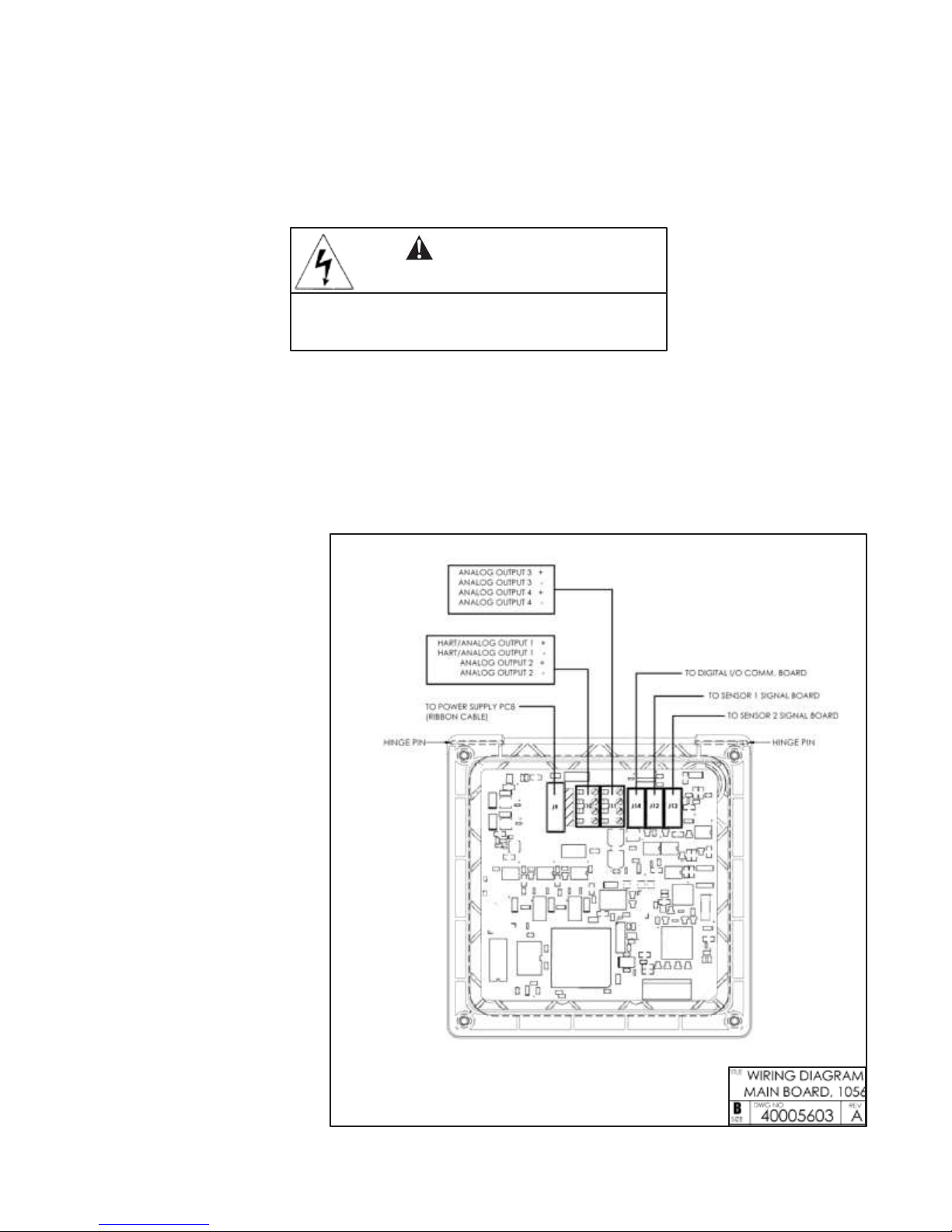
3.1.2 Analog output wiring
Four analog current outputs are
located on the main circuit
board, which is attached to the
inside of the enclosure door.
Figure 3-1 shows the location of
the terminals, the outputs they
are assigned to, and the polarity.
For best EMI/RFI protection, use
shielded output signal cable
enclosed in earth-grounded
metal conduit.
Keep output signal wiring separate from power wiring. Do not
run signal and power or relay
wiring in the same conduit or
close together in a cable tray.
FIGURE 3-1. Analog output connections.
The analog outputs are on the main board near the
hinged end of the enclosure door.
9
Page 19

MODEL FCL– 56
SECTION 3.0
WIRING
3.1.3 Alarm wiring.
WARNING
Exposure to some chemicals may degrade the sealing
properties used in the following devices: Zettler
Relays (K1-K4) PN AZ8-1CH12DSEA
The alarm relay terminal strip is located on the power
supply board, which is mounted on the left hand side of
the enclosure beneath the gray plastic cover. To remove
the cover, grab it by the upper edges and pull straight
out. The relay terminal strip is at the top of the board.
See Figure 3-2. Bring the relay wires through the rear
conduit opening on the left hand side of the enclosure
and make connections to the terminal strip.
Replace the cover. The two tabs on the back edge of
the cover fit into slots at the rear of the enclosure, and
the three small slots in the front of the cover snap into
the three tabs next to the relay terminal strip. See
Figure 3-2. Once the tabs are lined up, push the cover
to snap it in place.
Keep alarm relay wiring separate from signal wiring.
Do not run signal and power or relay wiring in the
same conduit or close together in a cable tray.
FIGURE 3-2. Alarm relay
connections.
3.2 SENSOR WIRING
The Model FCL is provided with sensor cables pre-wired to the transmitter. If it is necessary to replace the
sensor cable, refer to the instructions below.
1. Shut off power to the transmitter.
2. Loosen the four screws holding the front panel in place and let it drop down.
3. Locate the appropriate signal board.
Slot 1 (left)
Slot 2 (center)
Slot 3 (right)
communication
input 1 (chlorine)
input 2 (pH)
4. Loosen the gland fitting and carefully push the sensor cable up through the fitting as you pull the board
forward to gain access to the wires and terminal screws. Disconnect the wires and remove the cable.
5. Insert the new cable through the gland and pull the cable through the cable slot.
6. Wire the sensor to the signal board. Refer to the wiring diagrams in Figures 3-3 through 3-6.
7. Once the cable has been connected to the board, slide the board fully into the enclosure while taking up the
excess cable through the cable gland. Tighten the gland nut to secure the cable and ensure a sealed enclosure.
10
Page 20

MODEL FCL– 56
SECTION 3.0
WIRING
WHITE
RED
Figure 3-3. Wiring Diagram
for Free Chlorine Sensor
Figure 3-4. Wiring Diagram
for 399VP-09 pH Sensor
Figure 3-5. Wiring Diagram
for 3900VP-10 pH sensor (gray cable)
Figure 3-6. Wiring Diagram
for 3900VP-10 pH sensor (blue cable)
11
Page 21

MODEL FCL– 56
This page left blank intentionally
12
Page 22

MODEL FCL– 56
SECTION 4.0
DISPLAY AND OPERATION
I sensor current (chlorine)
mV
mV input (pH)
Slp
slope (pH)
R.Z
reference impedance (pH)
Gl.Z
glass impedance (pH)
SECTION 4.0
DISPLAY AND
OPERATION
4.1. MAIN DISPLAY
The transmitter has a four line display. See Figure 4-1. The display can be customized to meet user requirements.
See
Section 4.5. Fault or warning messages, if appropriate, appear at the bottom of the screen. See Section 11.1.
1. ppm
7. pH
T1: 25.0qC
T2: 25.0qC
O1: 12.00 mA
O2: 12.00 mA
O3: 12.00 mA
O4: 12.00 mA
Warning
Press
INFO
key
FIGURE 4-1. Main Display
The following abbreviations are used in the lower two lines of the display. The number following the abbreviation
refers to the sensor, alarm relay, or output.
O output T
temperature (live)
Tm
temperature (manual)
M
measurement
AL
alarm relay
4.2. KEYPAD
Local communication with the transmitter is through the membrane keypad. See Figure 4-2.
FIGURE 4-2. Transmitter
keyp
ad.
13
Page 23

MODEL FCL– 56
SECTION 4.0
DISPLAY AND OPERATION
Data
storage
and ret
rieval
HART
Time and date
R
eset
1
Analog
S1
measurement
4-20 mA
Lin
ear
0
1
Analog
S1
measurement
4-20 mA
Lin
ear
0
1
2
S1
measurement
4-20 mA
Lin
ear
0
1
Analog
S1
measurement
4-20 mA
Lin
ear
0
S1:
1.00 ppm 25.0qC
S2:
7.00 pH
25.0qC
O
utputs Relays M
easure
Temp
erature
Security
O
utput
Analog/PID/Simulat
e
A
ssign
R
ange
Scal
e
Dampening
sec
NEXT
BACK
4.3 OPERATION
The operation of the Model 56 can best be understood from the following example.
S1:
1.00 ppm 25.0qC
S2:
7.00 pH
25.0qC
Calibrat
e
Pr
ogram
Hold
Display setup
S1:
1.00 ppm 25.0qC
S2:
7.00 pH
25.0qC
O
utputs Relays M
easure
Temperature
Security
O
utput
Analog/PID/Simulat
e
A
ssign
R
ange
Scal
e
Dampening
sec
NEXT
BACK
S1:
1.00 ppm 25.0qC
S2:
7.00 pH
25.0qC
O
utputs Relays M
easure
Temperature
Security
O
utput
Analog/PID/Simulat
e
A
ssign
R
ange
Scal
e
Dampening
sec
NEXT
BACK
S1:
1.00 ppm 25.0qC
S2:
7.00 pH
25.0qC
Outputs Relays
Measure
Temperature Secu
rity
Output
1
Analog/PID/Simulat
e
A
ssign
R
ange
Scal
e
1. With the main display showing (Figure 4-1), press the ENTER/MENU key.
The main menu, shown at left, will appear. Pressing the ENTER/MENU
key will bring up the main menu only if the main display is showing.
Note that the current reading and temperature for sensor 1 (S1) and
sensor (S2), if applicable, always appear at the top of the screen.
The cursor (dark blue backlit field) is on the Calibrate button. Press the
down key to move the cursor to the Program button.
2. Press the ENTER/MENU key. The cursor is on the outputs tab and the
first screen in the outputs sub-menu is showing.
To select a different program submenu use the right key to move the cursor
to the desired tab and press ENTER/MENU.
3. To enter th e outputs submenu, press the dow n key. The cursor moves to the
first control box, Output. The Model 56 has four analog outputs, and this
control lets the user select which output to configure.
4. The default is output 1. To select a different output, press the
ENTER/MENU key. A list of the available outputs, shown two at a time,
appears. To view the list, press or press and hold the up or down key.
To select and store the highlighted selection, press ENTER/MENU.
Dampening
sec
NEXT
BACK
S
5. To move from one control box to another, press the up or down key.
6. Some controls require the user to select an item from a list. Others, like the
dampening control, require the user to enter a number. Move the cursor to
Dampening at the bottom of the screen.
14
Page 24

MODEL FCL– 56
SECTION 4.0
DISPLAY AND OPERATION
1
Analog
S1
measurement
4-20 mA
Lin
ear
S1:
1.00 ppm 25.0qC
S2:
7.00 pH
25.0qC
O
utput
s Relay
s M
easure
Temp
erature
Securit
y
O
utput
Analog/PID/Simulat
e
A
ssign
R
ange
Scal
e
Dampening
sec
NEXT
BACK
S1:
1.00 ppm 25.0qC
S2:
7.00 pH
25.0qC
O
utputs Relays M
easure
Temperature
Security
Dampening applies
to the
output only,
not the
main
display. Increasing
the
dampening
time
reduces the
noise on the
output,
but
increases
the
response time
.
1
Analog
S1
measurement
4-20 mA
Lin
ear
S1:
1.00 ppm 25.0qC
S2:
7.00 pH
25.0qC
O
utputs Relays M
easure
Temperature
Security
O
utput
Analog/PID/Simulat
e
A
ssign
R
ange
Scal
e
Dampening
sec
NEXT
BACK
S1:
1.00 ppm 25.0qC
S2:
7.00 pH
25.0qC
O
utputs Relays M
easure
Temperature
Security
Range: 0/4 mA
0.000 ppm
Range: 20 mA 10.00
pp
m
Fault Fixed
Fault
current
22.00 mA
BACK
7. The default dampening value is 0 seconds. To change the value, press
ENTER/MENU. The dark blue back-lighting will disappear indicating that
a number can be entered. Use the numeric keypad to enter the desired
number. If you make an error, press the left key to erase the digit last
entered. To store the number, press ENTER/MENU.
S
8. Every control box has an information or help screen associated with it. To
view the information screen for the control box the cursor is on, press the
INFO key. The information screen for the Dampening control is shown at
left. To close the information screen, press any key.
9. A NEXT and BACK button are at the bottom of the screen. Th e NEXT button
means that additional control boxes are available on at least one more
screen. To view the next screen, use the navigation keys (either down or
right) to move the cursor to NEXT an d press ENTER/MENU.
10. The next screen in the Outputs sub-menu appears. The cursor is on the
outputs tab. To enter the screen, press the down navigation key.
11. To return to the previous screen, move the cursor to BACK and press
ENTER/MENU.
12. To return to the main menu, press EXIT.
15
Page 25

MODEL FCL– 56
SECTION 4.0
DISPLAY AND OPERATION
4.4 HOLD
4.4.1 Purpose
To prevent unwanted alarms and improper operation of control systems or dosing pumps, place the alarm
relays and outputs assigned to the sensor in hold before removing the sensor for maintenance. Hold is also
useful if calibration, for example, buffering a pH sensor, will cause an out of limits condition. During hold,
outputs assigned to the sensor remain at the last value, and alarms assigned to the sensor remain in their
present state.
4.4.2 Using the Hold Function.
The hold function uses certain programming features not discussed in Section 4.3.
S1:
1.00 ppm 25.0qC
S2:
7.00 pH
25.0qC
1. With the main display showing, press ENTER/MENU. The main menu will
appear. Choose Hold. The screen shown at left appears. The cursor is on
Hold what?
Sensor 1 output(s)
and
alarm relay(s
)
Sensor 2 output(s)
and
alarm relay(s
)
the first check box. To hold outputs and relays associated with sensor 1,
press ENTER/MENU. A check will appear in the check box. To put
Transmitter will
remain in hold
until
taken out of hold.
To
take
transmitter
out of hold, move the
cursor
to th
e
checked
item and press ENTER.
sensor 2 on hold also, move the cursor to the sensor 2 line and press
ENTER/MENU to check the sensor 2 hold box.
APPLY
BACK
S1:
1.00 ppm 25.0qC
S2:
7.00 pH
25.0qC
2. To activate Hold, move the cursor to the APPLY button at the bottom left
of the screen and press ENTER/MENU. The selected sensor outputs and
Hold what?
9
Sensor 1 output(s)
and
alarm relay(s
Sensor 2 output(s)
and
alarm relay(s
)
alarm relays will remain on hold until taken out of hold. However, if power
is lost then restored, hold will automatically be turned off.
Transmitter will
remain in hold
until
taken out of hold.
To
take
transmitter
out of hold, move the
cursor
to th
e
checked
item and press ENTER.
APPLY
BACK
3. The screen describes how to take the transmitter out of hold. Be sure
to press APPLY once the box has been unchecked.
1.
ppm
7.
pH
4. A message stating which sensors are in hold will appear in the fault/warning
banner at the bottom of the main display.
T1: 25.0qC
T2: 25.0qC
O1: 12.00 mA
O3: 12.00
mA
O2: 12.00 mA
O4: 12.00
mA
S1
Hold
16
Page 26

MODEL FCL– 56
SECTION 4.0
DISPLAY AND OPERATION
Measure 1
10.00
ppm
ppm
0.00
1 day
Measure 2
0.00
p
H
p
H
14.00
1 day
BACK
S1: 1.00 ppm 25.0qC S2: 7.00 pH 25.0qC
G
raphics
Display setup
Tag Languag
e
W
arning
Measure 1
Measure 2
Temp 1 Output 1 mA Output 3 mA
Temp 2
Output 2 mA
Output 4 mA
BACK
4.5 MAIN DISPLAY
4.5.1 Configuring the main display
The main display can be configured to meet specific user requirements.
S1: 1.00 ppm 25.0qC S2: 7.00 pH 25.0qC
Graphics Display
setup Tag Language W
arning
View
graph
1. With the main display showing, press ENTER/MENU. The main menu will
appear. Choose Display Setup. The screen shown at left appears.
Variable (y-axis
)
Y-axis (maximum)
Y-axis (
minimum)
X-axis (
time
)
Upper graph Lower
graph
S1: 1.00 ppm 25.0qC S2: 7.00 pH 25.0qC
Graphics Display
setup Tag Language W
arning
2. Move the cursor the Display setup tab and press ENTER/MENU. The
screen shown at left appears.
Configure
main
display
Set brightness
BACK
3. Choose Configure main display. The screen at left appears. The position
of each control box corresponds to the position of the variable in the main
display. Move the cursor to the control box and press ENTER/MENU. Use
the up and down keys to scroll through the list of variables and press
ENTER/MENU to select the desired variable for display.
4.5.2 Setting brightness
Move the cursor to the Set brightness button in the screen shown in step 2 in Section 4.5.1 and press
ENTER/MENU. Then, move the cursor to the Display brightness control and select the desired brightness. The
information screen gives recommendations about setting the brightness level especially in areas where the
ambient temperature exceeds 121°F (50°C).
17
Page 27

MODEL FCL– 56
SECTION 4.0
DISPLAY AND OPERATION
4.6 SECURITY
4.6.1 How the Security Code Works
Security codes prevent accidental or unwanted changes to program settings or calibrations. There are three levels
of security.
a. A user can view the main display and diagnostic screens only.
b. A user has access to the calibration and hold menus only.
c. A user has access to all menus.
S1:
1.00 ppm 25.0qC
S2:
1.00 pH
25.0qC
Enter
security cod
e
1. If a security code has been programmed, pressing a sub-menu button
(See section 4.3) will cause the security screen shown at left to appear.
0
2. Enter the three digit security code.
3. If the entry is correct, the requested sub-menu will appear and the user
has access to all the sub-menus the code entitles him to.
4. If the entry is wrong, the invalid code screen appears.
4.6.1 Assigning Security Codes
See Section 5.7.
4.6.2 Bypassing Security Codes
Call the factory.
18
Page 28

MODEL FCL– 56
SECTION 5.0
PROGRAMMING THE
Data
storage
and re
trieval
HART
Time and date
Reset
Calibrate Pr
ogram Hold
Display setup
1
Analog
S1 measurement
4-20 mA
Linear
0
S1:
1.00 ppm 25.0qC
S2:
7.00 pH
25.0qC
O
utput
s Relay
s Measure
Tempera
tur
e
Securit
y
O
utput
Analog/PID/Simulat
e
A
ssign
R
ang
e
Scal
e
Dampening
sec
NEXT
BACK
SECTION 5.0
PROGRAMMING THE
TRANSMITTER
5.1 ENTERING THE PROGRAM MENUS
S1:
1.00 ppm 25.0qC
S2:
7.00 pH
25.0qC
1. With the main display showing, press ENTER/MENU to display the main
menu. Move the cursor to Program and press ENTER/MENU.
2. Move the cursor to the tab showing the desired sub menu and press
ENTER/MENU. A fifth tab, not shown, labeled pH diagnostics setup, will
be present if one of the sensors is a pH sensor.
5.2 OUTPUTS
5.2.1 Menu Tree
Figure 5-1 is the Outputs menu tree.
Outputs
Output 1, 2, 3, or 4
Analog PID
Simulate
A
ssign
Rang
e
Scale
Da
mpening
Range 0/4
mA
Range 20
mA
Fault
Fault current
A
ssign
Rang
e
Se
tpoint
LR
V
URV
Proportional
band
I
ntegra
l
De
rivativ
e
Fault
Fault current
Hold at X mA
FIGURE 5-1. Menu tree for the Outputs sub menu.
19
Page 29

MODEL FCL– 56
SECTION 5.0
PROGRAMMING THE
5.2.2. Settings
Move the cursor to the appropriate control box and make the desired setting. For more information about the control box the cursor is on press INFO. To close the information screen, press any key.
5.3 RELAYS
5.3.1 Menu Tree
Figure 5-2 is the Relays menu tree.
Relays
Delay timer Date and time Fault
Simulate
Assign relay
Type (delay timer
)
Assign
measuremen
t
High/low
Se
tpoint
Deadband
On
tim
e
Delay
time
Normal
state
Assign relay
Type (date and
time)
Week 1
Set
tim
e
Set
dur
ation
Week 2
Set
tim
e
Set
dur
ation
Assign rel
ay
Type
(fault)
Normal
state
Assign relay
En
ergi
ze/de-en
ergi
ze
FIGURE 5-2. Menu tree for the Relays sub menu.
20
Page 30

MODEL FCL– 56
SECTION 5.0
PROGRAMMING THE
S1:
1.00 ppm 25.0qC
S2:
7.00 pH
25.0qC
Outputs Relays Measure
Temperature
Security
Explanation
of
relay acti
ons
Configure relay
Simulate relay action
BACK
S1:
1.00 ppm 25.0qC
S2:
7.00 pH
25.0qC
Outputs Relays Measure
Temperature
Security
Setpoint alarm info
Delay timer info
Interval timer info
Date and
time timer info
TPC
info
Totalizer
based
timer info
Bleed and feed
info
Fault info
BACK
1
Setpoint
S1
measurement
High
10.00
0.00
S1:
1.00 ppm 25.0qC
S2:
7.00 pH
25.0qC
Outputs Relays Measure
Temperature
Security
Relay
Type
Assign
Logic
Setpoint
ppm
Deadband
ppm
NEXT BACK
5.3.2. Settings
1. A large number of relay actions are available in the Model 56. For more
information about a relay action, move the cursor the Explanation of relay
actions button and press ENTER/MENU.
2. The screen at left appears. Select the desired relay action and press
INFO to display the information screen. To close the information screen,
press any key.
The totalizer-based relay timer is not available in the FCL. It is available
only if one of the measurements is flow.
To configure a relay, press EXIT to return to the screen in step 1.
3. Move the cursor to the Configure relay button and press ENTER/MENU.
A screen similar to the one at left will appear.
4. Move the cursor to the appropriate control box and make the desired setting. For more information about the control the cursor is on press INFO.
To close the information screen, press any key.
21
Page 31

MODEL FCL– 56
SECTION 5.0
PROGRAMMING THE
5.4 MEASUREMENT
5.4.1 Menu Tree
Figure 5-3 is the Measurements menu tree.
Measurement
Sensor 1 or 2
Sensor 1 (Cl) Sensor 2 (pH)
Measurement
Units
R
esolution
pH
correction*
Filter
Dual slope calibration
* For FCL-02,
choose, Live/automatic.
For FCL-01,
choose manual
and set
manual
pH to the
expected pH
of the
process liq
uid
.
Pre-amplifier location
Filter
Reference
impedance
Wiring
R
esolution
Solution temperature
corre
ction
*
Isopotential pH
* If the pH
measurement
is being made to
correct th
e
chlorine sensor reading, leave solution
temper
atur
e
correction off.
FIGURE 5-3. Menu tree for the Measurements sub menu.
5.4.2. Settings
Move the cursor to the appropriate control box and make the desired setting. For more information about the control the cursor is on press INFO. To close the information screen, press any key.
5.5 TEMPERATURE
5.5.1 Menu Tree
Figure 5-4 is the Temperature menu tree.
Temperatur
e
Sensor 1 or 2
Sensor 1 (Cl) Sensor 2 (pH)
Units
Automatic/manual*
* If
manual, specify manual tempe
rature.
Units
Automatic/manual*
* If
manual, specify manual tempe
rature.
FIGURE 5-4. Menu tree for the Temperature sub menu.
22
Page 32

MODEL FCL– 56
SECTION 5.0
PROGRAMMING THE
5.5.2. Settings
Move the cursor to the appropriate control box and make the desired setting. For more information about the con-
trol the cursor is on press INFO. To close the information screen, press any key.
5.6 pH DIAGNOSTIC SETUP
5.6.1 Menu Tree
Figure 5-5 is the pH diagnostic setup menu tree.
5.5.2. Settings
Move the cursor to the appropriate control box and make the desired setting. For more information about the control the cursor is on press INFO. To close the information screen, press any key.
5.6 pH DIAGNOSTIC SETUP
5.6.1 Menu Tree
Figure 5-5 is the pH diagnostic setup menu tree.
pH diagno
stics
Sensor 2 (pH)
Maximum allowed
offset
Minimum allowed sl
ope
Maximum allowed sl
ope
Sensor
diagnostics
on/o
ff
Ref
fault high
Glass fault
high
Glass impedance
temp
correction
on/
off
Glass impedance measurement met
hod
FIGURE 5-5. Menu tree for the pH diagnostic setup sub menu.
5.6.2. Settings
Move the cursor to the appropriate control box and make the desired setting. For more information about the control the cursor is on press INFO. To close the information screen, press any key.
5.7 SECURITY
5.7.1 Menu Tree
Figure 5-6 is the security setup menu tree.
Security
Calibration/hold
All
FIGURE 5-6. Menu tree for the security setup sub menu.
5.7.2. Settings
Move the cursor to the appropriate control box and make the desired setting. For more information about the control the cursor is on press INFO. To close the information screen, press any key.
5.8 RESTORING DEFAULT SETTINGS
See section 6.7.
23
Page 33

MODEL FCL– 56
This page left blank intentionally
24
Page 34

MODEL FCL– 56
SECTION 6.0
CALIBRA
TION
Data
storage
and retrieval
HART
Time
and date
Reset Calibrate
Pr
ogram Hold
Display setup
Output 1
Output 2
Output 3
Output 4
S1 Measurement
S1 Tempera
tur
e
S2 Measurement
S2 Tempera
tur
e
SECTION 6.0
CALIBRA
TION
6.1 INTRODUCTION
The calibrate menu allows the user to do the following:
1. Calibrate the RTD (temperature sensing element) in the chlorine and pH sensors.
2. Calibrate the chlorine sensor.
3. Calibrate the pH sensor. Four methods are available.
a. Two-point automatic buffer calibration
b. Manual two-point buffer calibration
c. Standardization (one-point calibration) against either a grab sample or an in-process measurement
d. Manual entry of pH sensor slope and offset if they are already known
4. Calibrate the analog outputs.
6.2 ENTERING THE CALIBRATION MENUS
S1:
1.00 ppm 25.0qC
S2:
7.00 pH
25.0qC
1. With the main display showing, press ENTER/MENU to display the main
menu. The cursor will be on Calibrate. Press ENTER/MENU.
BACK
S1:
1.00 ppm 25.0qC
S2:
7.00 pH
25.0qC
2. Choose the sensor (measurement or temperature) or output to be calibrated.
Sensor 1 (S1) is the free chlorine sensor; sensor 2 (S2) is the pH sensor
(if present).
BACK
6.3 CALIBRATING TEMPERATURE
To calibrate the temperature device in the sensor, choose S1 temperature or S2 temperature and follow the prompts.
If you want more information about a calibration step, press the INFO key. Once the calibration is complete, the screen
will show the results of the calibration. The screen will also show some acceptance criteria to help you determine
whether to accept the calibration. Press the INFO key for an information screen to aid with troubleshooting if the
calibration results are not acceptable.
25
Page 35

MODEL FCL– 56
SECTION 6.0
CALIBRA
TION
6.4 CALIBRATING THE FREE CHLORINE SENSOR
S1:
1.00 ppm 25.0qC
S2:
7.00 pH
25.0qC
Why
is calibration necessary?
To
find
out press INFO.
Otherwise, choose
the
desired calibration me
thod.
Zero
Grab
1. Choosing sensor 1 (free chlorine) in section 6.2 causes the screen shown
at left to appear. There are two steps to calibrating a free chlorine sensor,
measuring the zero current (zero) an d determining th e slope of the calibration
curve (grab). Because stable free chlorine standards in the ppm range do
not exist, the sensor must be calibrated against the results of a laboratory
test run on a grab sample.
BACK
2. To zero the sensor, select Zero and follow the prompts. For more
information about preparing the zero solution and measuring the zero
current, press the INFO key when prompted.
If the zero step is successful, the transmitter will display the zero
complete screen and the measured zero current. The screen will also
show the typical zero current for the sensor and the recommended
acceptance criterion. You will be asked to accept the zero current.
Press the INFO key for an information screen to aid with
troubleshooting if the results are not acceptable.
If the zero current is badly in error, the transmitter will display the zero
failed screen. Press the INFO key for troubleshooting.
3. To calibrate the sensor response in chlorinated water, select Grab and fol low
the prompts. Be sure the sensor is installed in the flow cell in the FCL and
the sample is overflowing the inside tube in the overflow sampler. If you
are calibrating the FCL-02, calibrate the pH sensor first and install it
in its flow cell before calibrating the free chlorine sensor.
If the calibration is successful, the transmitter will display the calibration
complete screen and the sensitivity (nA/ppm). The screen will also show
the typical sensitivity range for the sensor and th e recommended acceptance
criterion. You will be asked to accept the calibration. Press the INFO key
for an information screen to aid with troubleshooting if the calibration is
not acceptable.
If the sensitivity is badly in error, the transmitter will display the
calibration failed screen. Press the INFO key for troubleshooting.
26
Page 36

MODEL FCL– 56
SECTION 6.0
CALIBRA
TION
Why is
calibration necessary?
To find out press INFO.
Otherwise, choose
the
desired calibration
met
hod.
Auto
buffer
Slope
/off
set
Manual
buffer
Standardize (grab)
Standardize
(in process
)
6.5 CALIBRATING THE pH SENSOR
S1:
1.00 ppm 25.0qC
S2:
7.00 pH
25.0qC
1. Choosing sensor 2 (pH) in section 6.2 causes the screen shown at left to
appear. There are five possible ways to calibrate the pH sensor. Select
the desired calibration method (auto buffer is recommended) and follow
the prompts. For more information about calibration methods, press the
INFO key
BACK
S1:
1.00 ppm 25.0qC
S2:
7.00 pH
25.0qC
Start Calib
ration
Setup auto calib
ration:
2. If yo u choose auto buffer calibration, the screen at left will appear to
allow you to setup auto buffer calibration parameters. The default values
are recommended.
Stabilization time
Stabilization delta
Buffer list
10
0.02
sec
p
H
NIST
BACK
3. If the calibration is successful, the transmitter will display the calibration
results (slope and offset for automatic and manual buffer calibration and
offset for standardize calibration).
If there is a possible calibration error, the transmitter will display the
calibration results and the nature of the error. You will be asked to accept th e
calibration. Press the INFO key for an information screen to aid with
troubleshooting if the calibration is not acceptable.
If there is a serious calibration error, the transmitter will display the
calibration results and the error. Press the INFO key for an information
screen to aid with troubleshooting and repeat the calibration.
6.6 CALIBRATING THE ANALOG OUTPUTS
Choose the appropriate output in section 6.2 and follow the prompts to trim the selected output. If the calibration is
successful the trim complete screen will appear. If the entered value is more than 1.0 mA different from the simulated
output current, the transmitter will display the possible error screen, and you will be asked to accept the calibration.
Press the INFO key for an information screen to aid with troubleshooting if the calibration is not acceptable.
6.7 RESET
6.7.1 Purpose
There are three resets.
1. Reset all user settings, including calibration and program settings, to the factory default values. The
transmitter will return to Quick Start. The event logger and data logger (See section 8.0) will be
unaffected.
2. Reset sensor calibration to the default value. The transmitter will clear all user-entered calibration data for
the selected sensor. It will leave all other user-entered data unaffected.
3. Reset the analog output calibration for the selected output to the default value. The transmitter will leave all
other user-entered settings unchanged.
6.7.2 Procedure
1. With the main display showing, press ENTER/MENU to display the main menu. Move the cursor to Reset and
press ENTER/MENU.
2. Check the desired boxes and press APPLY.
27
Page 37

MODEL FCL– 56
This page left blank intentionally
28
Page 38

MODEL FCL– 56 SECTION 7.0
DIGITAL COMMUNICA
TIONS
SECTION 7.0
DIGITAL COMMUNICA
TIONS
The Model 56 transmitter supplied with the FCL has HART communications as a
st
andard
feature. For more information refer to the Model 56 HART Addendum
Manual.
29
Page 39

MODEL FCL– 56
This page left blank intentionally
30
Page 40

MODEL FCL– 56
SECTION 8.0
DATA AND EVENT LOGGING AND
RETRIEV
AL
Data
storage
and
retrieval
HART
Time and date
R
eset
SECTION 8.0
DATA AND EVENT LOGGING AND
RETRIEV
AL
8.1. OVERVIEW
Data and event logging is a standard feature in the Model 56 transmitter. However, the feature must be enabled.
When data/event logging is enabled, the Model 56 transmitter will automatically store the following events with
date
and time stamp: faults, warnings, calibration data, calibration results (pass or fail), power on/off cycles, hold on/off,
and new sensor board detected. At the user’s discretion the transmitter will also store alarm activation and
deactivation as events. The event logger holds 300 events. When the capacity of the logger is reached, the
oldest events are removed to make room for new events.
When data/event logging is enabled, the transmitter will automatically store the following measurement
data.
Free
chlorine:
date and time, ppm chlorine, temperature, and sensor current.
pH: date and time, pH, temperature, mV, glass impedance, reference impedance, and raw pH (if displayed pH
has a solution temperature correction applied).
The transmitter can store up to 30 days of data. When the capacity of the logger is reached, the oldest data
are removed to make room for new data. Data storage frequency is once every 30 seconds.
8.2. CONFIGURATION
S1:
1.00 ppm 25.0qC
S2:
7.00 pH
25.0qC
Calib
rate
Program
Hold
Display setup
S1:
1.00 ppm 25.0qC
S2:
7.00 pH
25.0qC
Configure Download
View e
vents
Data/event logger
is
currently
D
isabled
1. With the main display showing, press MENU/ENTER. Choose Data storage
and retrieval
2. The screen shown at left appears. The data logger is currently disabled
(default). To enable the data logger, move the cursor to the Enable
data/event logger button and press ENTER/MENU.
Enable
data/event logger
Disable data/event logger
BACK
3. Mak e the appropriate date and time settings and choose which alarm
relay activations and deactivations to record as events.
NOTE
Setting
the date or time to an earlier value than the one currently showing
will cause data to be lost from the data/event logger. Download data
before resetting time or date. See section 8.3.
Page 41

MODEL FCL– 56
SECTION 8.0
DATA AND EVENT LOGGING AND
RETRIEV
AL
31
Page 42

MODEL FCL– 56
SECTION 8.0
DATA AND EVENT LOGGING AND
RETRIEV
AL
8.3. DOWNLOADING DATA AND EVENTS
To download data or events, move the cursor to the download tab and press ENTER/MENU. Unscrew the USB
port cover in the lower right hand corner of the front panel and insert a USB flash drive in the port. Press the
appropriate button to download data or events. Downloading may take as long as 20 minutes. During download,
the display and keypad are frozen, but all other transmitter functions continue.
Downloaded data and events are stored in a spreadsheet. There is a separate spreadsheet for every day of data.
The filename for downloaded data is dl mmddyy or dl ddmmyy, depending on the date and time format selected by the user. The filename for downloaded events is el mmddyy or el ddmmyy.
8.4. VIEWING EVENTS
The event log can be viewed on the Model 56 display. Move the cursor the View events tab and press ENTER/MENU.
Move the cursor to the View Events button and press ENTER/MENU.
To scroll through the list of events move the cursor to the DOWN or UP key at the bottom of the screen and press
and hold ENTER/MENU.
8.5. DATE AND TIME
The date and time can also be reset from the main menu by pressing the Time and Date button.
NOTE
Setting the date or time to an earlier value than the one showing will cause data to be lost from
the da ta/event logger. Download data before resetting time or date. See section 8.3.
32
Page 43

MODEL FCL– 56
SECTION 9.0
GRAPHICAL DISPLAY
Data
storage
and re
trieval
HART
Time and date
Reset
Measure 1
10.00
ppm
ppm
0.00
1 day
Measure 2
0.00
pH
pH
14.00
1 day
BACK +
9.1. OVERVIEW
SECTION 9.0
GRAPHICAL
DISPLAY
The Model 56 has a dual graphical display. Each graph can be configured to meet user requirements, although
the time axis on both graphs must be the same. The time scale can be one hour, one day, seven days, or 30 days.
9.2. CONFIGURATION
S1:
1.00 ppm 25.0qC
S2:
7.00 pH
25.0qC
Calibrat
e
Pr
ogram
Hold
Display setup
S1:
1.00 ppm 25.0qC
S2:
7.00 pH
25.0qC
Graphics Display
setup Tag
Language Warning
View
graph
Upper graph Lower
graph
Variable (y-axis)
Y-axis (maximum)
Y-axis (
minimum)
X-axis
(tim
e)
S1:
1.00 ppm 25.0qC
S2:
7.00 pH
25.0qC
S1 ppm
1. With the main display showing, press MENU/ENTER. Choose Display setup.
2. The screen shown at left appears. Configure the displayed variable,
the maximum and minimum values for the y-axis, and the time scale.
To view the graphs, move the cursor to the View graph button and
press ENTER/MENU.
3. The time axis can be expanded or shrunk. To expand the time scale,
use the left or right navigation keys to move the pair of dotted green
2
0
S2 pH
8
lines to the area of interest. Press the up navigation key to expand the
graph. To shrink the time axis, press the down navigation key.
+
7
12/09 03:13
12/09 09:13 12/0915:13 12/09 21:13
12/10 03:13
BACK
33
Page 44

MODEL FCL– 56
This page left blank intentionally
34
Page 45

MODEL FCL– 56
SECTION 10.0
MAINTENANCE
SECTION 10.0
MAINTENANCE
10.1 TRANSMITTER
The transmitter used with the FCL needs little routine maintenance.
Clean the transmitter case and front panel by wiping with a clean soft cloth dampened with water ONLY. Do not
use solvents, like alcohol, that might cause a buildup of static charge.
Sensor circuit boards are replaceable.
PN
24207-00
pH/ORP/ISE sensor board
24203-01
chlorine sensor board
To replace a board
WARNING
RISK OF ELECTRICAL SHOCK
Disconnect main power and relay contacts wired to
separate power source before servicing
1. Turn off power to the transmitter.
2. Loosen the four screws holding the front panel in place and let the front panel drop down.
3. Loosen the gland fitting and carefully push the sensor cable up through the fitting as you pull out the circuit
board.
4. Once you have access to the terminal strip, disconnect the sensor.
5. Unplug the sensor board from the main board. See Figure 3-2.
6. Slide the replacement board partially into the board slot. Plug the sensor board into the main board and reattach
the sensor wires.
7. Carefully pull the sensor cable through the gland fitting as you push the sensor board back into the enclosure.
Tighten the cable gland.
8. Close the front panel.
9. Turn on power.
35
Page 46

MODEL FCL– 56
SECTION 10.0
MAINTENANCE
10.2 CHLORINE SENSOR
10.2.1 General.
When used in clean water, the chlorine sensor requires little maintenance. Generally, the sensor needs maintenance
when the response becomes sluggish or noisy or when readings drift following calibration. For a sensor used in
potable water, expect to clean the membrane every month and replace the membrane and electrolyte solution every
three months. In water containing large amounts of suspended solids, for example open recirculating cooling water,
membrane cleaning or replacement will be more frequent.
10.2.2 Cleaning the membrane.
Clean the membrane with water sprayed from a wash bottle. Do not use tissues to clean the membrane.
10.2.3 Replacing the electrolyte solution and membrane.
CAUTION
Fill solution may cause irritation. May be harmful if
swallowed. Read and follow manual.
1. Unscrew the membrane retainer and remove the membrane assembly and O-ring. See Figure 10-1.
2. Hold the sensor over a container with the cathode pointing down.
3. Remove the fill plug and allow the electrolyte solution to drain out.
4. Inspect the cathode. If it is tarnished, clean it using a cotton-tipped swab dipped in baking soda or alumina. Use
type A dry powder alumina intended for metallographic polishing of medium and soft metals. Rinse thoroughly
with water.
5. Wrap the plug with two turns of pipe tape and set aside. Remove old tape first.
6. Prepare a new membrane. Hold the membrane assembly with the cup formed by the membrane and membrane
holder pointing up. Fill the cup with electrolyte solution and allow the wooden ring to soak up the solution (usually
takes several minutes).
7. Hold the sensor at about a 45-degree angle with the cathode end pointing up. Add electrolyte solution through
the fill hole until the liquid overflows. Tap the sensor near the threads to release trapped air bubbles. Add more
electrolyte solution if necessary.
8. Place the fill plug in the electrolyte port and begin screwing it in. After several threads have engaged, rotate
the sensor so that the cathode is pointing up and continue tightening the fill plug. Do not overtighten.
9. Place a new O-ring in the groove around the cathode post. Cover the holes at the base of the cathode stem
with several drops of electrolyte solution.
10. Insert a small blunt probe, like a toothpick with the end cut off, through the pressure equalizing port. See
Figure 10-1.
NOTE
Do not use a sharp probe. It will puncture the bladder and destroy the sensor.
Gently press the probe against the bladder several times to force liquid through the holes at the base of the
cathode stem. Keep pressing the bladder until no air bubbles can be seen leaving the holes. Be sure the holes
remain covered with electrolyte solution.
11. Place a drop of electrolyte solution on the cathode, then place the membrane assembly over the cathode.
Screw the membrane retainer in place.
12. The sensor may require several hours operating at the polarizing voltage to equilibrate after the electrolyte
solution has been replaced.
36
Page 47

MODEL FCL– 56
SECTION 10.0
MAINTENANCE
FIGURE 10-1. Chlorine Sensor Parts
TABLE 10-2. Spare Parts
33523-00
Electrolyte Fill Plug
9550094
O-Ring, Viton 2-014
33521-00
Membrane Retainer
23501-08
Free Chlorine Membrane Assembly: includes one membrane assembly and one O-ring
23502-08
Free Chlorine Membrane Kit: includes 3 membrane assemblies and 3 O-rings
9210356
#4 Free Chlorine Sensor Fill Solution, 4 oz (120 mL)
10.3 pH SENSOR
10.3.1 General.
When used in clean water, the pH sensor requires little maintenance. Generally, the sensor needs maintenance when
the response becomes sluggish or noisy. In clean water the typical cleaning frequency is once a month. In water
containing large amounts of suspended solids, for example open recirculating cooling water, cleaning frequency will
be substantially greater.
10.3.2 Cleaning the Sensor
Remove soft deposits by rinsing with a stream of water from a wash bottle. If the sensor becomes coated with
rust, dissolve the rust by soaking the sensor in dilute citric acid (dissolve 5 grams citric acid crystals in 100 mL of
water) for no longer than 30 minutes at room temperature. Rinse the sensor thoroughly with water and soak in
pH 4 buffer for several hours. Recalibrate the sensor in buffers before returning it to service.
10.3.3 Other Maintenance
The 3900VP-02-10 or the older 399VP-09 sensor supplied with the Model FCL-02 is disposable. It has no
replaceable parts.
37
Page 48

MODEL FCL– 56
SECTION 10.0
MAINTENANCE
10.4 CONSTANT HEAD FLOW CONTROLLER
10.4.1 General
After a period of time, deposits may accumulate in the constant head overflow chamber and in the tubing leading
to the flow cell(s). Deposits increase the resistance to flow and cause the flow to gradually decrease. Loss of flow
may ultimately have an impact on the chlorine sensor performance. The flow controller is designed to provide about
2 gal/hr (120 mL/mm) flow. Loss of flow to about 1 gal/hr (60 mL/mm) causes about a 5% decrease in chlorine
sensor output. Loss of flow has almost no effect on pH sensor performance other than to increase the overall
response time.
10.4.2 Cleaning the flow controller
The low flow controller can be taken apart completely for cleaning. Use a strong flow of water to flush out the tubing.
A pipe cleaner or a small bottlebrush can remove more adherent deposits. To prevent leaks, apply a thin layer of
silicone grease (or equivalent) to the two O-rings at the base of overflow chamber and to the O-ring sealing the
central overflow tube to the base.
10.4.3 Other Maintenance
Table 10-2 and Figure 10-2 show the replacement parts for the flow controller assembly used in Model FCL-01.
Table 10-3 and Figure 10-3 show replacement parts for the flow controller assembly used in Model FCL-02.
38
Page 49

MODEL FCL– 56
SECTION 10.0
MAINTENANCE
TABLE 10-3. Replacement parts for constant head flow controller assembly (Model FCL-01)
Location in
Figure 10-2
PN
Description
Shipping
Weight
1
24039-00
Flow cell for chlorine sensor with bubble shedding nozzle
1 lb/0.5 kg
2
24040-00
O-ring kit, two 2-222 and one 2-024 silicone O-rings,
with lubricant
1 lb/0.5 kg
3
33812-00
Dust cap for constant head flow controller
1 lb/0.5 kg
4
9322032
Elbow, ¼ in FNPT x ¼ in OD tubing
1 lb/0.5 kg
5
9350029
Check valve, ¼ in FNPT
1 lb/0.5 kg
6
33823-00
Outside tube for constant head device
1 lb/0.5 kg
FIGURE 10-2. Replacement Parts for the Flow Controller Assembly used in Model FCL-01.
39
Page 50

MODEL FCL– 56
SECTION 10.0
MAINTENANCE
TABLE 10-4. Replacement parts for constant head flow controller assembly (Model FCL-02)
Location in
Figure 10-3
PN
Description
Shipping
Weight
1
24039-00
Flow cell for chlorine sensor with bubble shedding nozzle
1 lb/0.5 kg
2
24039-01
Flow cell for pH sensor
1 lb/0.5 kg
3
24040-00
O-ring kit, two 2-222 and one 2-024 silicone O-rings,
with lubricant
1 lb/0.5 kg
4
33812-00
Dust cap for constant head flow controller
1 lb/0.5 kg
5
9322032
Elbow, ¼ in FNPT x ¼ in OD tubing
1 lb/0.5 kg
6
9350029
Check valve, ¼ in FNPT
1 lb/0.5 kg
7
33823-00
Outside tube for constant head device
1 lb/0.5 kg
FIGURE 10-3. Replacement Parts for the Flow Controller Assembly used in Model FCL-02.
40
Page 51

MODEL FCL– 56
SECTION 11.0
TROUBLESHOOTING
Outputs
information
Transmitter
info
rmation
HART
info
rmation
Faults –
fix
now
Warnings – fix
soon
Sensor 1 information
Sensor 2 information
Outputs
information
Transmitter
info
rmation
HART
info
rmation
SECTION 11.0
TROUBLESHOOTING
11.1 OVERVIEW
The transmitter continuously monitors itself and the sensor(s) for problems. When the transmitter identifies a
problem, the word warning or fault appears intermittently at the bottom of the display. To read the fault or warning
message and troubleshooting information, press INFO. See section 11.2.
A warning means the instrument or sensor is usable, but steps should be taken as soon as possible to correct the
condition causing the warning. Warning messages can be turned off. To turn off warning messages, go to the main
menu and choose Display setup. Scroll to the Warning tab and turn off warning messages.
A fault means the measurement is seriously in error and is not to be trusted. A fault condition might also mean that
the transmitter has failed. Fault conditions should be corrected immediately. When a fault occurs, the analog
output goes to 22.00 mA or to the value programmed in Section 5.2. Fault messages cannot be turned off.
11.2 READING AND TROUBLESHOOTING FAULT AND WARNING MESSAGES
S1:
1.00 ppm 25.0qC
S2:
7.00 pH
25.0qC
1. With the main display showing, press the INFO key. The screen at left
appears. Move the cursor to the appropriate button and press
ENTER/MENU.
BACK
S1:
1.00 ppm 25.0qC
S2:
7.00 pH
25.0qC
Warn: S2 Out of R
ange
Press INFO for
troubleshooting.
BACK
2. A screen like the one at left will appear showing all the warning or fault
messages. For troubleshooting information press the INFO key
11.3 SENSOR DIAGNOSTICS
Sensor diagnostic readings are often useful in troubleshooting measurement problems.
S1:
1.00 ppm 25.0qC
S2:
7.00 pH
25.0qC
1. With the main display showing, press the INFO key. Move the cursor to
the Sensor 1 or Sensor 2 information button and press ENTER/MENU.
Faults –
fix
now
Warnings – fix
soon
Sensor 1 information
Sensor 2 information
BACK
2. A list of sensor diagnostics will appear. For more information about a specific
diagnostic measurement, move the cursor to the diagnostic of interest and
press the INFO key.
41
Page 52

MODEL FCL– 56
SECTION 11.0
TROUBLESHOOTING
11.4 TROUBLESHOOTING CALIBRATION PROBLEMS
If a calibration attempt results in an error or a likely error, the transmitter will display the appropriate warning
screen. For troubleshooting suggestions, press the INFO key.
11.5 OTHER TROUBLESHOOTING — CHLORINE
Although calibration troubleshooting information is available in the transmitter by pressing the INFO key,
troubleshooting information for process measurement problems is not.
Problem
See Section
Process readings are erratic
11.5.1
Readings drift
11.5.2
Sensor does not respond to changes in chlorine level
11.5.3
Chlorine reading spikes following rapid change in pH
11.5.4
11.5.1 Process readings are erratic
1. Readings are often erratic when a new sensor or a rebuilt sensor is first placed in service. The current usually
stabilizes after a few hours.
2. Are the holes between the membrane and the electrolyte reservoir open? Unscrew the membrane retainer and
remove the membrane assembly. Inspect the holes at the base of the cathode stem. If they appear to be
plugged, use a straightened paper clip or pin to remove blockages.
3. Verify that wiring is correct. Pay particular attention to shield and ground connections.
4. If automatic pH correction is being used, check the pH reading. If the pH reading is noisy, the chlorine reading
will also be noisy. If the pH sensor is the cause of the noise, use manual pH correction until the problem with
the pH sensor can be corrected. Also, refer to Section 11.6.3 and 11.6.4 for troubleshooting noisy pH readings.
5. Is the membrane in good condition and is the sensor filled with electrolyte solution? Replace the fill solution
and electrolyte. Refer to Section 10.0 for details.
11.5.2 Readings drift
1. Is the sample temperature changing? The transmitter automatically corrects for changes in sensor
current caused by temperature changes. The time constant for the temperature measurement is about five
minutes. Therefore, the reading may drift for a while after a sudden temperature change.
2. Is the membrane clean? For the sensor to work properly, chlorine must diffuse freely through the membrane.
A coating on the membrane will interfere with the passage of chlorine, resulting in slow response. Clean the
membrane by rinsing it with a stream of water from a wash bottle. DO NOT use a tissue to wipe the membrane.
3. Is the sample flow within the recommended range? Gradual loss of sample flow will cause a downward drift.
Be sure the liquid level in the constant head sampler is level with the central overflow tube and that excess
sample is flowing down the tube. If necessary, disassemble and clean the overflow sampler. See Section 10.4.
4. Is the sensor new or has it been recently serviced? New or rebuilt sensors may require several hours to stabilize.
5. Is the pH of the process changing? If manual pH correction is being used, a gradual change in pH will cause
a gradual change in the chlorine reading. As pH increases, chlorine readings will decrease, even though the
free chlorine level (as determined by a grab sample test) remained constant. If the pH change is no more than
about 0.2, the change in the chlorine reading will be no more than about 10% of reading. If the pH changes
are more than 0.2, use automatic pH correction.
6. Is a bubble trapped against the membrane? For the sensor to work properly, the chlorine must continuously
diffuse through the membrane. Bubbles block the chlorine in the sample from reaching the membrane, so
readings drift downward as bubbles form and grow. The nozzle at the bottom of the flow cell pushes bubbles
to the edges of the membrane where they do no harm. In cold samples the nozzle may not be as effective.
a. If bubbles are visible, confirm that they are blocking the membrane by removing the sensor from the flow
cell and replacing it. Removing the sensor breaks the bubbles, so when the sensor is replaced, readings
return to normal.
b. Confirm that the nozzle is properly positioned in the flow cell. Line up your eye with the bottom of the membrane
retainer. No gap should be visible between the end of the nozzle and membrane retainer.
42
Page 53

MODEL FCL– 56
SECTION 11.0
TROUBLESHOOTING
11.5.3 Sensor does not respond to changes in chlorine level.
1. Is the grab sample test accurate? Is the grab sample representative of the sample flowing to the sensor?
2. Is sample flowing past the sensor? Be sure the liquid level in the constant head sampler is level with the central
overflow tube and that excess sample is flowing down the tube. If necessary, disassemble and clean the over
flow sampler. See Section 10.4.
3. Is the pH compensation correct? If the transmitter is using manual pH correction, verify that the pH value in
the transmitter equals the actual pH to within ±0.1 pH. If the transmitter is using automatic pH correction,
check the calibration of the pH sensor.
4. Is the membrane clean? Clean the membrane and replace it if necessary. Check that the holes at the base
of the cathode stem are open. Unscrew the membrane retainer and remove the membrane assembly. Locate
the small holes at the base of the cathode stem. Use a straightened paper clip to clear the holes. Replace the
electrolyte solution.
5. Replace the sensor.
11.5.4 Chlorine readings spike following sudden changes in pH (automatic pH correction).
Changes in pH alter the relative amounts of hypochlorous acid (HOCl) and hypochlorite ion (OCl-) in the sample.
Because the sensor responds only to HOCl, an increase in pH causes the sensor current (and the apparent chlorine
level) to drop even though the actual free chlorine concentration remained constant. To correct for the pH effect, the
transmitter automatically applies a correction. Generally, the pH sensor responds faster than the chlorine sensor.
After a sudden pH change, the transmitter will temporarily over-compensate and gradually return to the correct
value. The time constant for return to normal is about 5 minutes.
11.6 OTHER TROUBLESHOOTING — pH
Although calibration troubleshooting information is available in the transmitter by pressing the INFO key,
troubleshooting information for process measurement problems is not.
Problem
See Section
Sensor does not respond to known pH changes
11.6.1
Calibration was successful, but process pH is slightly different from expected value
11.6.2
Calibration was successful, but process pH is grossly wrong or noisy
11.6.3
pH readings are moderately noisy and tend to wander
11.6.4
11.6.1 Sensor Does Not Respond to Known pH Changes.
1. Is the pH sensor responsive to buffers? Check sensor response in two buffers at least two pH units apart.
2. Did the expected pH change really occur? Use a second pH meter to verify the change.
3. Is sample flowing past the sensor? Be sure the liquid level in the constant head sampler is level with the central
overflow tube and that excess sample is flowing down the tube. If necessary, disassemble and clean the over
flow sampler. See Section 10.4.
4. Is the sensor properly wired to the transmitter? See Section
3.2.
5. Is the glass bulb cracked or broken? Go to sensor diagnostics and check the glass electrode impedance. See
Section 11.3.
6. Is the transmitter working properly? Check the transmitter by simulating the pH input. See Section
11.9.
11.6.2 Buffer Calibration Is Acceptable, Process pH Is Slightly Different from Expected Value.
Differences between pH readings made with an on-line instrument and a laboratory or portable instrument are
normal. The on-line instrument is subject to process variables, for example ground potentials, stray voltages, and
orientation effects that may not affect the laboratory or portable instrument. To make the process reading agree
with a referee instrument, standardize the sensor. See Section 6.5.
43
Page 54

MODEL FCL– 56
SECTION 11.0
TROUBLESHOOTING
11.6.3 Calibration Was Successful, but Process pH Is Grossly Wrong and/or Noisy.
Grossly wrong or noisy readings suggest a ground loop (measurement system connected to earth ground at more
than one point), a floating system (no earth ground), or noise being brought into the transmitter by the sensor
cable. The problem arises from the process or installation. It is not a fault of the transmitter. The problem should
disappear once the sensor is taken out of the system. Check the following:
1. Is a ground loop present?
a. Verify that the system works properly in buffers. Be sure there is no direct electrical connection between the
buffer containers and the process liquid or piping.
b. Strip back the ends of a heavy gauge wire. Connect one end of the wire to the process piping or place it in
the process liquid. Place the other end of the wire in the container of buffer with the sensor. The wire makes
an electrical connection between the process and sensor.
c. If offsets and noise appear after making the connection, a ground loop exists.
2. Is the process grounded?
a. The measurement system needs one path to ground: through the process liquid and piping. Plastic piping,
fiberglass tanks, and ungrounded or poorly grounded vessels do not provide a path. A floating system can
pick up stray voltages from other electrical equipment.
b. Ground the piping or tank to a local earth ground.
c. If noise still persists, simple grounding is not the problem. Noise is probably being carried into the instrument
through the sensor wiring.
3. Simplify the sensor wiring.
a. Disconnect all sensor wires at the transmitter except, IN REFERENCE, IN pH, RTD IN and RTD RETURN.
See the wiring diagrams in Section 3.2.
b. Tape back the ends of the disconnected wires to keep them from making accidental connections with other
wires or terminals.
c. Connect a jumper wire between the RTD RETURN and RTD SENSE terminals (see wiring diagrams in
Section 3.2).
d. If noise and/or offsets disappear, the interference was coming into the transmitter through one of the
sensor wires. The system can be operated permanently with the simplified wiring.
4. Check for extra ground connections or induced noise.
a. To avoid induced noise in the sensor cable, keep the unit as far away as possible from power cables, relays,
and electric motors.
b. If ground loops persist, consult the factory. A visit from an experienced technician may be required to solve
the problem.
11.6.4 pH Readings Are Moderately Noisy and Tend to Wander.
pH readings that are moderately noisy (±0.1 pH) and tend to wander are probably caused by bubbles getting
trapped against the pH sensor. Although the overflow sampler is designed to allow bubbles to escape before they
reach the pH sensor and the sensor itself is designed so trapped air bubbles don’t interfere with the measurement,
bubbles may occasionally be a problem. Shaking the sensor will dislodge the bubbles. If bubbles remain a
problem, call the factory.
44
Page 55

MODEL FCL– 56
SECTION 11.0
TROUBLESHOOTING
11.7 OTHER TROUBLESHOOTING — GENERAL
Problem
See Section
Current output is too low
11.7.1
Alarm relays do not operate properly
11.7.2
11.7.1 Current Output Is Too Low.
Load resistance is too high. Maximum is 550Ω.
11.7.2 Alarm Relays Do Not Operate Properly
1. Verify the relays are properly wired.
2. Verify the relays are properly configured.
11.8 SIMULATING INPUTS — CHLORINE
To check the performance of the transmitter, use a decade box
and
1.5V battery to simulate the current from the sensor. The battery, which
opposes the polarizing voltage, is necessary to ensure that the sensor
current has the correct sign.
1. Disconnect the anode and cathode leads from terminals 8 and 10 on
TB1 and connect a decade box and 1.5V battery as shown in Figure
11-1. It is not necessary to disconnect the RTD leads.
R
2. Set the decade box to 2.8MΩ.
3. Note the sensor current. It should be about 500 nA. The actual
value depends on the voltage of the battery. To view the sensor
7
ANOD SHLD
8 ANOD
9
CATH SHLD
10
CATH
current, go to the main display and press INFO. Choose sensor 1
information. The input current is the second line in the display.
FIGURE 11-1. Simulating Chlorine
Change the decade box resistance and verify that the correct current is shown. Calculate current from the
equation:
current (nA) =
V
battery
— 200 (voltages in mV)
resistance (MΩ)
The voltage of a fresh 1.5 volt battery is about 1.6 volt (1600 mV).
45
Page 56

MODEL FCL– 56
SECTION 11.0
TROUBLESHOOTING
11.9 SIMULATING INPUTS — pH
11.9.1 General
This section describes how to simulate a pH input into
the transmitter. To simulate a pH measurement, connect
a standard millivolt source to the transmitter. If the
transmitter is working properly, it will accurately measure
the input voltage and convert it to pH.
11.9.2 Simulating pH input.
1. Set automatic temperature correction to manual
and set manual temperature to 25°C. See Section
5.5
2. Disconnect the sensor and connect a jumper wire
between the IN REFERENCE and IN pH terminals.
3. Press INFO and choose sensor 2 information (pH).
The input voltage should be 0 mV and the pH should
be 7.00. Because calibration data stored in the analyzer may be offsetting the input voltage, the displayed
pH may not be exactly 7.00.
4. If a standard millivolt source is available, disconnect
the jumper wire between IN REFERENCE and IN pH
and connect the voltage source as shown in Figure
11-2. Be sure to jumper the IN REFERENCE and
GND SOL terminals.
5. Calibrate the transmitter using the manual buffer pro-
cedure. Use 0.0 mV for Buffer 1 (pH 7.00) and -177.4
mV for Buffer 2 (pH 10.00). If the transmitter is
working properly it should accept the calibration. The
slope should be 59.16 mV/pH and the offset should
be zero.
6. To check linearity, set the voltage source to the val-
ues shown in the table and verify that the pH and millivolt readings match the values in the table.
FIGURE 11-2. Simulating pH Input.
Voltage (mV)
pH (at 25°)
295.8
2.00 177.5
4.00 59.2
6.00 -59.2
8.00 -177.5
10.00
-295.8
12.00
46
Page 57

MODEL FCL– 56
SECTION 11.0
TROUBLESHOOTING
11.10 SIMULATING INPUTS — TEMPERATURE
11.10.1 General.
The transmitter accepts a Pt100 RTD (for pH and chlorine
sensors). The Pt100 RTD is in a three-wire configuration.
See Figure 9-5.
11.10.2 Simulating temperature
To simulate the temperature input, wire a decade box to
the transmitter as shown in Figure 11-4.
To check the accuracy of the temperature measurement, set
the resistor simulating the RTD to the values in the table and
note the temperature readings. The measured temperature
might not agree with the value in the table. During sensor
calibration an offset might have been applied to make the
measured temperature agree with a standard thermometer.
The offset is also applied to the simulated resistance. The
transmitter is measuring temperature correctly if the
difference between measured temperatures equals the
difference between the values in the table to within ±0.1°C.
For example, start with a simulated resistance of 103.9 Ω
,
which corresponds to 10.0°C. Assume the offset from the
sensor calibration was -0.3 Ω. Because of the offset, the
transmitter calculates temperature using 103.6 Ω. The
result is 9.2°C. Now change the resistance to 107.8 Ω,
which cor- responds to 20.0°C. The transmitter uses 107.5
Ω to calculate the temperature, so the display reads
19.2°C. Because the difference between the displayed
temperatures (10.0°C) is the same as the difference
between the simulated temper- atures, the transmitter is
working correctly.
FIGURE 11-3. Three-Wire RTD Configuration.
Although only two wires are required to connect
the RTD to the transmitter, using a third (and
some- times fourth) wire allows the transmitter
to correct for the resistance of the lead wires and
for changes in the lead wire resistance caused by
changes in ambient temperature.
FIGURE 11-4. Simulating RTD Inputs.
Temp. (°C)
Pt 100 (Ω)
0
100.0
10
103.9
20
107.8
25
109.7
30
111.7
40
115.5
50
119.4
60
123.2
70
127.1
80
130.9
85
132.8
90
134.7
100
138.5
47
Page 58

NOTES
48
Page 59

NOTES
49
Page 60

FCL with 56 Transmitter
LIQ-MAN-FCL-56
Global Headquarters
Emerson Automation Solutions
8200 Market Blvd.
Chanhassen, MN 55317, USA
+1 800 999 9307 or +1 952 906 8888
+1 952 949 7001
Liq.CSC@Emerson.com
Latin America Regional Office
Emerson Automation Solutions
1300 Concord Terrace, Suite 400
Sunrise, FL 33323, USA
+1 954 846 5030
+1 952846 5121
RFQ.RMD-RCC@Emerson.com
Europe Regional Office
Emerson Automation Solutions Europe GmbH
Neuhofstrasse 19a P.O. Box 1046
CH 6340 Baar
Switzerland
+1 954 846 5030
+1 952846 5121
RFQ.RMD-RCC@Emerson.com
Asia Pacific Regional Office
Emerson Automation Solutions Asia Pacific Pte LTD
1 Pandan Crescent
Singapore 128461
+65 6777 8211
+65 6777 0947
Enquiries@AP.Emerson.com
Middle East and Africa Regional Office
Emerson Automation Solutions
Emerson FZE P.O. Box 17033 Jebel
Ali Free Zone - South 2
+971 4 8118100
+971 4 88665465
RFQ.RMTMEA@Emerson.com
Instruction Manual
July 2017
Analyticexpert.com
Linkedin.com/company/Emerson-Automation-Solutions
Twitter.com/Rosemount_News
Facebook.com/Rosemount
Youtube.com/user/RosemountMeasurement
Google.com/+RosemountMeasurement
The Emerson logo is a trademark and service mark of Emerson
Electric Co.
Rosemount and Rosemount logotype are trademarks of
Emerson. All other marks are the property of their respective
owners.
© 2017 Emerson. All rights reserved.
 Loading...