

Page 1
00809-0100-4928, Rev AE
Rosemount™ 928 Wireless Gas Monitor
Reference Manual
September 2019
Page 2

Safety information
Read this manual before working with this product. For personal and system safety and for optimum product performance, make
sure to thoroughly understand the contents before installing, using, or maintaining this product.
The United States has two toll-free assistance numbers and one international number.
Customer Central: 1 800 999 9307 (7:00 a.m. to 7:00 p.m. Central Time)
National Reponse Center: 1 800 654 7768 (24 hours a day) for equipment service needs
International: 1 952 906 8888
NOTICE
Read this document before working with the product. For personal and system safety, and for optimum product performance,
make sure you thoroughly understand the contents before installing, using, or maintaining this product. For technical assistance,
contacts are listed below:
Customer Central
Technical support, quoting, and order-related questions.
United States - 1-800-999-9307 (7:00 am to 7:00 pm Central Time)
Asia Pacific- 65 777 8211
Europe/Middle East/Africa - 49 (8153) 9390
North American Response Center
Equipment service needs.
1-800-654-7768 (24 hours—includes Canada)
Outside of these areas, contact your local Emerson representative.
WARNING
Explosions
Explosions could result in death or serious injury.
Installation of device in an explosive environment must be in accordance with appropriate local, national, and international
standards, codes, and practices.
Review Product certifications for any restrictions associated with a safe installation.
Before connecting a handheld communication device in an explosive atmosphere, ensure the instruments are installed in
accordance with Intrinsically Safe or non-incendive field wiring practices.
When connecting an external device to the Rosemount 928's discrete output in a hazardous area, ensure that the external
device is installed in accordance with Intrinsically Safe or non-incendive field wiring practices.
WARNING
Electrical shock
Electrical shock could cause death or serious injury.
Avoid contact with the leads and terminals. High voltage that may be present on leads can cause electrical shock.
CAUTION
Nuclear applications
The products described in this document are not designed for nuclear qualified applications. Using non-nuclear qualified products
in applications that require nuclear-qualified hardware or products may cause inaccurate readings.
For information on Rosemount nuclear-qualified products, contact an Emerson sales representative.
2
Page 3

CAUTION
Installation problems
Only install the Rosemount 928 and all other wireless devices after the Wireless Gateway has been installed and is functioning
properly. Power up wireless devices in order of proximity from the Wireless Gateway, beginning with the closest. This will result in
a simpler and faster network installation.
CAUTION
Shipping considerations for wireless products
Battery hazards remain when cells are discharged.
The unit was shipped to you without the power module installed. Remove the power module prior to shipping.
Each power module contains two "C" size primary lithium batteries. Primary lithium batteries are regulated in transportation
by the US Department of Transportation and are also covered by IATA (International Air Transport Association), ICAO
(International Civil Aviation Organization), and ARD (European Ground Transportation of Dangerous Goods). It is the shipper's
responsibility to ensure compliance with these or any other local requirements. Consult current regulations and requirements
before shipping.
The power module with the wireless unit contains two "C" size primary lithium/thionyl chloride batteries. Each battery
contains approximately 2.5 grams of lithium, for a total of 5 grams in each pack. Under normal conditions, the battery
materials are self-contained and are not reactive as long as the batteries and the pack integrity are maintained. Take care to
prevent thermal, electrical, or mechanical damage. Protect contacts to prevent premature discharge.
Power modules should be stored in a clean and dry area. For maximum battery life, storage temperature should not exceed 86
°F (30 °C).
The power module has surface resisitivity greater than one gigaohm and must be properly installed in the wireless device
enclosure. Take care during transportation to and from the point of installation to prevent electrostatic charge buildup.
WARNING
Physical access
Unauthorized personnel may potentially cause significant damage to and/or misconfiguration of end users’ equipment. This could
be intentional or unintentional and needs to be protected against.
Physical security is an important part of any security program and fundamental to protecting your system. Restrict physical access
by unauthorized personnel to protect end users’ assets. This is true for all systems used within the facility.
3
Page 4

4
Page 5

Reference Manual Contents
00809-0100-4928 September 2019
Contents
Chapter 1 Introduction.................................................................................................................. 9
1.1 Using this manual.............................................................................................................................9
1.2 Models covered................................................................................................................................ 9
1.3 Device overview............................................................................................................................. 10
1.4 Product recycling/disposal............................................................................................................. 10
Chapter 2 Configuration...............................................................................................................11
2.1 Overview........................................................................................................................................ 11
2.2 Safety messages.............................................................................................................................11
2.3 Install the sensor............................................................................................................................ 12
2.4 Install the power module................................................................................................................14
2.5 Bench configuration....................................................................................................................... 15
2.6 HART® menu trees..........................................................................................................................17
2.7 Guided setup..................................................................................................................................20
2.8 Calibrating the sensor.....................................................................................................................47
2.9 Manual setup..................................................................................................................................70
2.10 Advanced options.........................................................................................................................86
2.11 Remove power module.............................................................................................................. 105
Chapter 3 Install.........................................................................................................................107
3.1 Overview...................................................................................................................................... 107
3.2 Safety messages...........................................................................................................................107
3.3 Wireless considerations................................................................................................................108
3.4 Electrical.......................................................................................................................................111
3.5 Verify operating atmosphere........................................................................................................111
3.6 Install the transmitter...................................................................................................................112
3.7 Rotate LCD display........................................................................................................................114
3.8 Ground the transmitter................................................................................................................ 115
3.9 External alarm device electrical connections.................................................................................115
Chapter 4 Commissioning.......................................................................................................... 119
4.1 Safety messages...........................................................................................................................119
4.2 Verify wireless network communication.......................................................................................120
4.3 Using Field Communicator to change the network ID and join key................................................124
4.4 Using AMS Wireless Configurator to change the network ID and join key......................................124
4.5 Verify operation........................................................................................................................... 124
4.6 If there is an immediate alarm...................................................................................................... 126
4.7 Troubleshoot communication...................................................................................................... 126
Chapter 5 Operation and maintenance.......................................................................................127
Rosemount 928 v
Page 6

Contents Reference Manual
September 2019 00809-0100-4928
5.1 Safety messages...........................................................................................................................127
5.2 LCD display screens...................................................................................................................... 128
5.3 Software features......................................................................................................................... 133
5.4 Resetting latched alarms.............................................................................................................. 135
5.5 Clearing process alarm history......................................................................................................141
5.6 Calibration history........................................................................................................................ 146
5.7 Sensor log.................................................................................................................................... 152
5.8 Bump testing................................................................................................................................159
5.9 Calibration....................................................................................................................................161
5.10 Sensor storage........................................................................................................................... 161
5.11 Replace the gas sensor............................................................................................................... 161
5.12 Replace the power module.........................................................................................................162
5.13 Replace the Ingress Protection filter........................................................................................... 165
5.14 Service support.......................................................................................................................... 166
Chapter 6 Troubleshooting........................................................................................................ 169
6.1 Overview...................................................................................................................................... 169
6.2 Rosemount™ 928 troubleshooting................................................................................................169
6.3 Digital concentration output is not reacting to presence of target gas..........................................176
6.4 LCD display troubleshooting.........................................................................................................176
6.5 Wireless network troubleshooting................................................................................................177
Appendix A Specifications and reference data............................................................................... 179
A.1 Specifications...............................................................................................................................179
A.2 Dimensional drawings..................................................................................................................182
A.3 Ordering information................................................................................................................... 183
Appendix B Product certifications................................................................................................. 187
B.1 European Directive information....................................................................................................187
B.2 Telecommunication compliance.................................................................................................. 187
B.3 FCC and IC.................................................................................................................................... 187
B.4 Ordinary location certification ..................................................................................................... 187
B.5 Installing in North America........................................................................................................... 187
B.6 USA.............................................................................................................................................. 187
B.7 Canada.........................................................................................................................................188
B.8 Europe..........................................................................................................................................189
B.9 International.................................................................................................................................190
B.10 China..........................................................................................................................................190
B.11 Japan.......................................................................................................................................... 190
B.12 Brazil.......................................................................................................................................... 191
B.13 Intrinsically Safe installation drawing..........................................................................................192
Appendix C High gain remote antenna option...............................................................................193
C.1 Safety messages...........................................................................................................................193
vi Emerson.com/Rosemount
Page 7

Reference Manual Contents
00809-0100-4928 September 2019
C.2 Antenna functional specifications.................................................................................................193
C.3 Installation considerations........................................................................................................... 194
C.4 Transient and lightning considerations.........................................................................................195
C.5 Dimensional drawing................................................................................................................... 196
C.6 Install the high gain remote antenna............................................................................................ 197
Appendix D Alert message mapping..............................................................................................201
D.1 Variable mapping.........................................................................................................................201
D.2 Alert mapping..............................................................................................................................201
Rosemount 928 vii
Page 8

Contents Reference Manual
September 2019 00809-0100-4928
viii Emerson.com/Rosemount
Page 9

Reference Manual
00809-0100-4928 September 2019
Introduction
1 Introduction
1.1 Using this manual
The sections in this manual provide information on installing, operating, and maintaining
the Rosemount™ 928 Wireless Gas Monitor. Models 928XSS00 and 928XUT00 are the
standard wireless gas monitors. Models 928XXSS01 and 928XUT01 include discrete
outputs, which can be used to trigger optional external device alarms, such as beacons or
annunciators, when an alarm condition occurs.
The manual sections are organized as follows.
Configuration contains information on the configuration and calibration of the
transmitter. You can configure with the AMS Wireless Configurator or Field
Communicator. This section also includes Field Communicator menu trees.
Install contains information on the installation of the transmitter, installation of the sensor
on the transmitter, and the wiring of external devices to the transmitter discrete output.
Commissioning contains information for the commissioning of the transmitter onto the
wireless network and how to verify that the transmitter has successfully joined.
Operation and maintenance provides detailed information on operation of the
transmitter. The chapter shows LCD display messages and includes maintenance
information, such as power module replacement, bump testing, and periodic calibration.
Troubleshooting provides descriptions and recommended corrective actions for common
errors and problems.
Specifications and reference data contains functional, physical, and performance
specifications, as well as ordering information.
Product certifications contains telecommunication compliance information, ordinary
location certification, hazardous locations certificates, and intrinsic safety installation
drawings.
High gain remote antenna option contains specifications, description, and installation
information for the optional high gain remote antenna.
Alert message mapping contains information about alerts in the HART® command, 48
additional status field and device variables, and variable mapping indexes for the
transmitter. This information can be used by DeltaV™ for alert monitoring and in the
Wireless Gateway for additional status mapping in Modbus®, OPC, or other
communications protocols.
1.2 Models covered
This manual covers the following modules
• Rosemount 928XSS00 Wireless Gas Monitor
— Ships with a separately specified Rosemount 628 Universal Gas Sensor.
• Rosemount 928UTX00 Wireless Gas Monitor
— Ships without a Rosemount 628 Universal Gas Sensor.
Rosemount 928 9
Page 10

Introduction Reference Manual
September 2019 00809-0100-4928
• Rosemount 928XSS01 Wireless Gas Monitor
— Wireless gas monitor with discrete output to be used as a switch for triggering
external equipment on an alarm state.
— Ships with a separately specified Rosemount 628 Universal Gas Sensor.
• Rosemount 928UTX021
— Wireless gas monitor with discrete output to be used as a switch for triggering
external equipment on an alarm state.
— Ships without a Rosemount 628 Universal Gas Sensor.
1.3 Device overview
The Rosemount 928 Wireless Gas Monitor uses the Rosemount 628 Universal Gas Sensor
to monitor the presence of toxic gases. The Rosemount 628 Universal Gas Sensor consists
of an electrochemical sensor inside a hot-swappable sensor module installed into the
transmitter housing. The transmitter sends the gas concentrations measured by the
sensor to the host system using the WirelessHART® protocol.
Electrochemical toxic sensors, such as those contained in the Rosemount 628 Series Gas
Sensor Module, consist of a set of electrodes separated by electrolyte material. When the
target gas is present inside the sensor housing, it oxidizes or reduces on the sensing
electrode. This creates an electric signal across the cell, which the transmitter interprets
and converts into a wireless-enabled signal.
1.4 Product recycling/disposal
Consider recycling equipment and packaging. Dispose of the product and packaging in
accordance with local and national legislations and regulations.
10 Emerson.com/Rosemount
Page 11

Reference Manual Configuration
00809-0100-4928 September 2019
2 Configuration
2.1 Overview
This section contains information on configuring the transmitter, including the sensor,
using Field Communicator or AMS Wireless Configurator. It also includes sensor calibration
information.
2.2 Safety messages
Instructions and procedures in this section may require special precautions to ensure the
safety of the personnel performing them.
WARNING
Follow installation guidelines.
Failure to follow these installation guidelines could result in death or serious injury.
Ensure that only qualified persons perform the installation.
WARNING
Explosions
Explosions could result in death or serious injury.
Before connecting a handheld communication device in an explosive atmosphere,
make sure that the instruments are installed in accordance with Intrinsically Safe or
non-incendive field wiring practices.
Verify that the operating atmosphere of the transmitter is consistent with the
appropriate hazardous locations certifications.
WARNING
Electrical shock
Electrical shock could cause death or serious injury.
Use extreme caution when making contact with the leads and terminals.
The power module may be replaced in a hazardous area. The power module has a
surface resistivity greater than one gigaohm and must be properly installed in the
wireless device enclosure. Take care during transportation to and from the point of
installation to prevent electrostatic charge buildup.
The surface resistivity of the antenna is greater than one gigaohm. To avoid
electrostatic charge buildup, do not rub or clean the antenna with solvents or a dry
cloth.
Substitution of components may impair intrinsic safety.
Rosemount 928 11
Page 12
Configuration Reference Manual
September 2019 00809-0100-4928
2.3 Install the sensor
The Rosemount™ 928 Wireless Gas Monitor is compatible with the Rosemount 628
Universal Gas Sensors. These sensors are contained within a sensor module that fits
integrally into the transmitter housing without using tools. Make electrical connections
when the sensor module is fully seated in the transmitter sensor module housing.
CAUTION
Install the Ingress Protection (IP) filter.
If the IP filter is not installed, damage may occur to the sensor inside the sensor.
Do not operate the transmitter without the correct IP filter installed in the sensor.
When installing the IP filter, verify that the IP filter gasket is in place and properly
aligned and that it does not block the white filter media. Refer to Figure 2-1.
When handling the IP filter, avoid contact with the filter media.
Verify that all three legs are fully latched by pushing upward on each leg of the IP filter.
Avoid getting water inside the IP filter.
Do not attempt to clean the IP filter.
Do not rinse or spray the IP filter with water.
Do not immerse the IP filter in water.
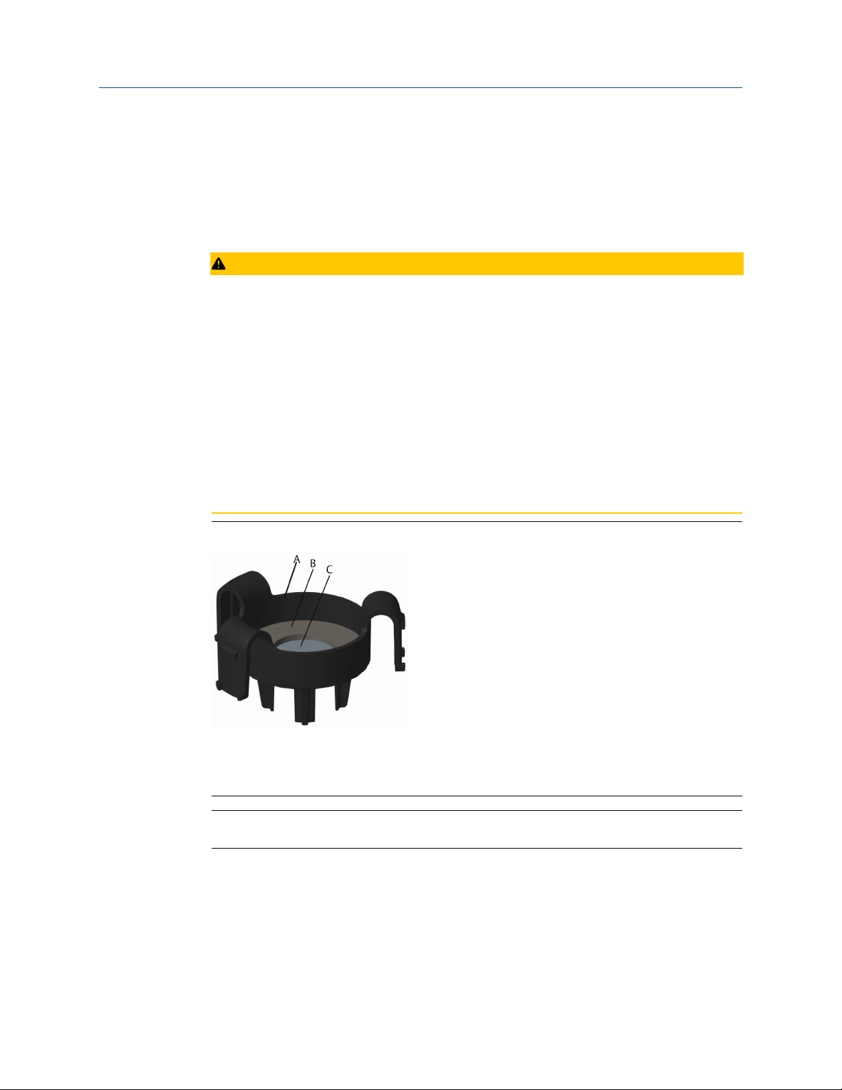
Figure 2-1: IP Filter
A. IP filter housing
B. IP filter gasket
C. Filter media
Note
Use Rosemount 628 Universal Gas Sensors only with the Rosemount 928 Transmitter.
The sensor is held in place using a tight-fitting seal and snap connections. The sensor is
connected to the transmitter by two latching tabs that fit into the bottom portion of the
housing as shown in Figure 2-2.
12 Emerson.com/Rosemount
Page 13
Reference Manual Configuration
00809-0100-4928 September 2019
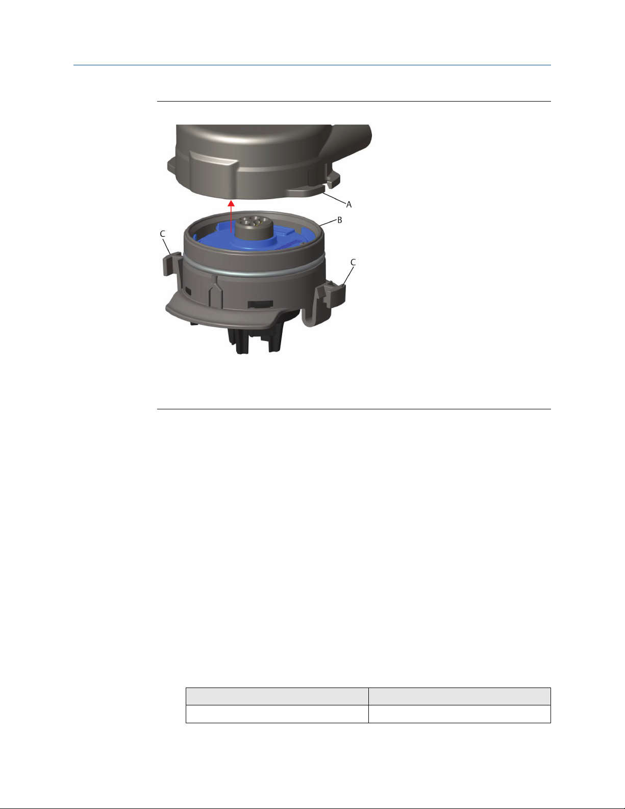
Figure 2-2: IP Filter Latching Tabs Locations
A. Transmitter housing
B. Gas sensor module
C. Latching tabs
The seal between the transmitter housing and the sensor assembly is designed so that a
snug, airtight fit is achieved between the two assemblies when properly installed.
Procedure
1. Remove the sensor from its packaging.
2. If installing a sensor on the transmitter for the first time, remove the protective
plastic cap from the sensor module housing.
3. The sensor contains a keying feature that ensures that the module cannot be forced
into the transmitter housing incorrectly. Confirm that the keying feature is aligned
by rotating it into position before installing the sensor into the transmitter.
4. Slide the sensor assembly up into the main transmitter housing until it is completely
seated.
5. To ensure a firm latch and seal, push the sensor upward until the two latching tabs
are fully engaged. Push up on the bottoms of the tabs after they are seated.
6. Allow the transmitter to warm up before continuing.
Refer to Table 2-1 for maximum warm up times based on gas type. During the
warm up period, the displayed values, alerts, and gas concentrations do not reflect
actual measurements; readings are not transmitted.
Table 2-1: Maximum Warm up Periods
Gas type Maximum warm up period
Hydrogen sulfide (H2S) One minute
Rosemount 928 13
Page 14
Configuration Reference Manual
September 2019 00809-0100-4928
Table 2-1: Maximum Warm up Periods (continued)
Gas type Maximum warm up period
Oxygen (O2) Seven minutes
Carbon monoxide (CO) One minute
Postrequisites
To remove the sensor, compress the two latching tabs and pull downward until the
module is released from the transmitter housing.
2.4 Install the power module
The transmitter is powered by the Emerson 701 SmartPower™ Module - Black. To connect
the module to the transmitter, do the following:
Procedure
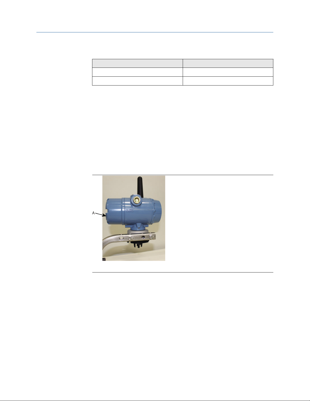
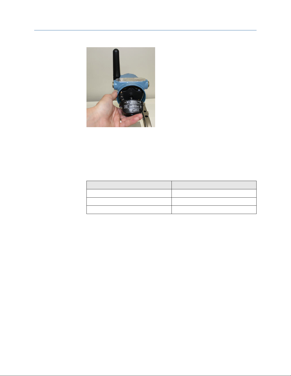
1. Remove the rear housing cover.
A. Rear housing cover
2. Connect the Emerson 701 SmartPower Module - Black.
14 Emerson.com/Rosemount
Page 15
Reference Manual Configuration
00809-0100-4928 September 2019
3. Verify the connection by viewing the LCD display.
4. Replace the rear housing cover and completely tighten.
5. Allow the transmitter to warm up before continuing.
Refer to Table 2-2 for maximum warm up times based on gas type. During the
warm up period, the displayed values, alerts, and gas concentrations do not reflect
actual measurements; readings are not transmitted.
Table 2-2: Maximum Warm up Periods
Gas type Maximum warm up period
Hydrogen sulfide (H2S) One minute
Oxygen (O2) Seven minutes
Carbon monoxide (CO) One minute
2.5 Bench configuration
To configure, you must install the sensor in a functional transmitter. The transmitter
receives any HART® communication from a handheld Field Communicator or from an AMS
Wireless Configurator.
Remove the rear housing cover to expose the terminal block and HART communication
terminals; then connect the power module to power the device for configuration.
2.5.1
Bench configure using a Field Communicator
A transmitter Device Description (DD) is required for HART® communication.
To connect to the transmitter using a handheld communication device, refer to Guided
setup. To obtain the latest DD, go to EmersonProcess.com/DeviceFiles and then visit the
Emerson web page for your handheld device.
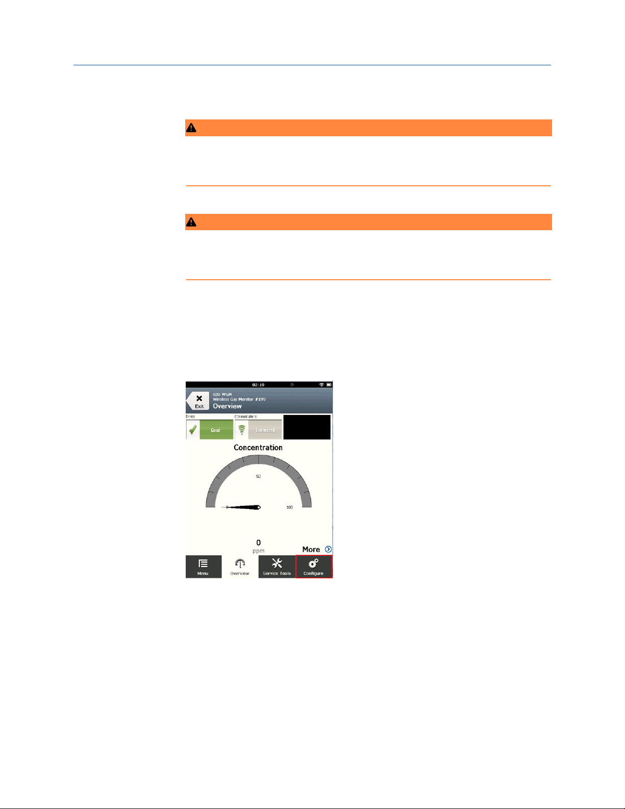
Procedure
1. On the Home screen, select Configure.
Rosemount 928 15
Page 16
Configuration Reference Manual
September 2019 00809-0100-4928
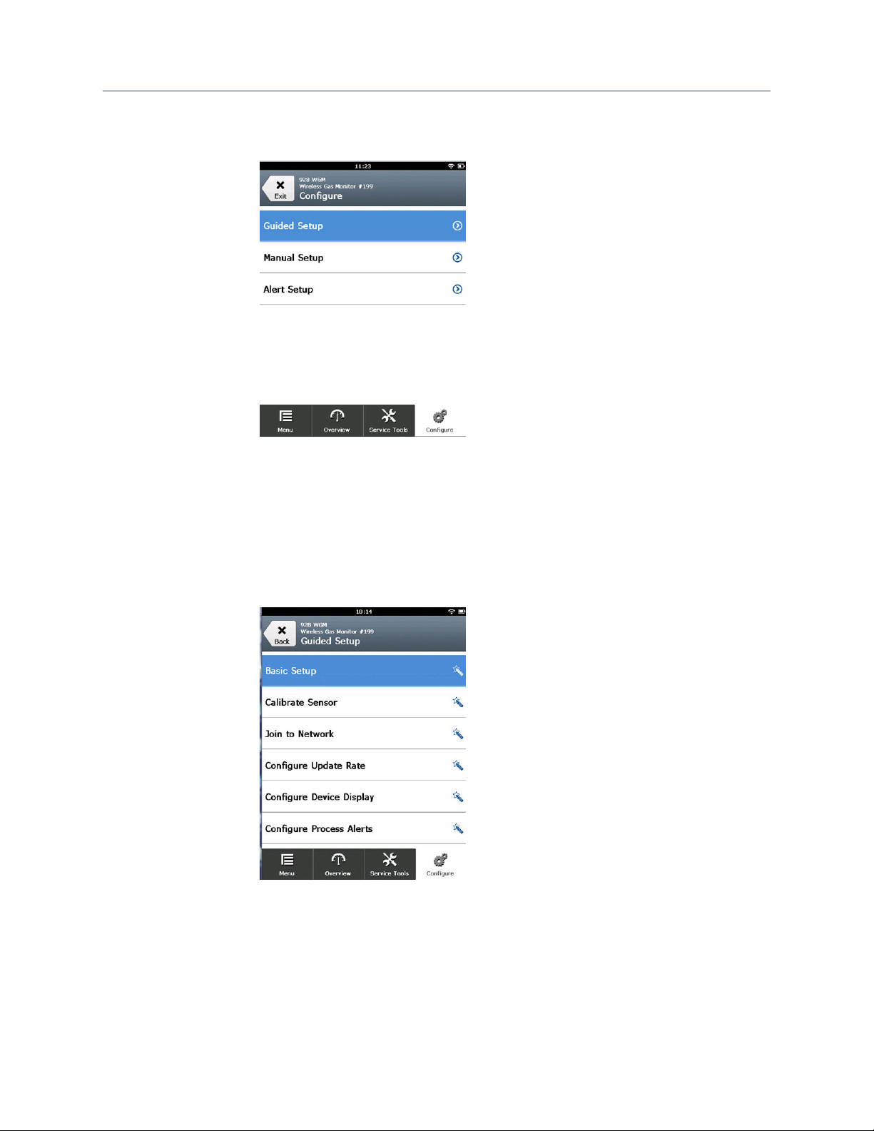
2. Do one of the following:
• On the Configure screen, select Guided Setup to verify or change initial
configuration settings. Refer to Guided setup. Refer to the Field Communicator
subsections for each configuration task.
• On the Configure screen, select Manual Setup to verify or change all
configuration settings, including optional advanced settings. Refer to Manual
setup. Refer to the Field Communicator subsections for each configuration task.
3. When finished, select Send to implement configuration changes.
4. When configuration is completed, remove the HART communications leads from
the COMM terminals on the terminal block and replace the rear housing cover.
2.5.2 Bench configure AMS Wireless Configurator
AMS Wireless Configurator is capable of connecting to devices directly, using a HART
modem, or though a Wireless Gateway.
Procedure
®
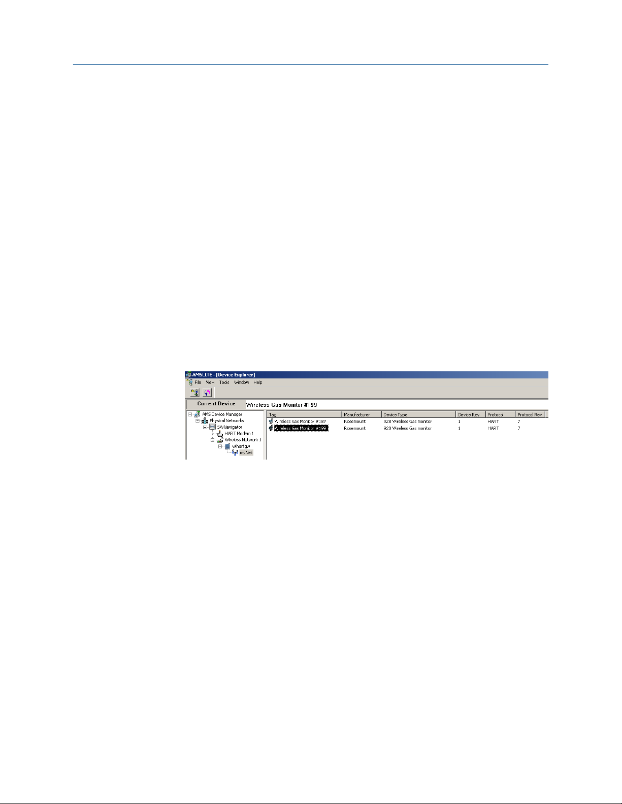
1. In the AMS Device Manager pane, select the HART modem.
2. In the device pane, double-click the device icon.
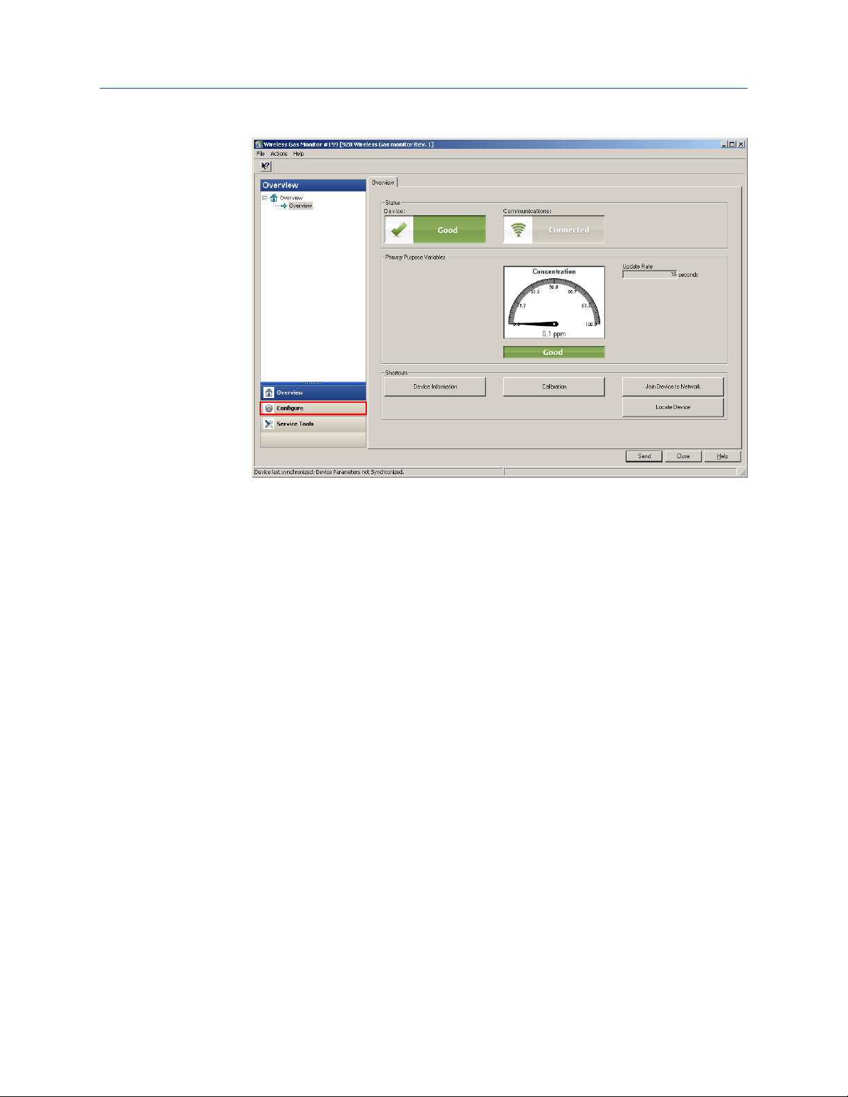
3. Select Configure.
16 Emerson.com/Rosemount
Page 17
Reference Manual Configuration
00809-0100-4928 September 2019
4. In the Configure pane, do one of the following:
• Select Guided Setup to verify or change initial configuration settings. Refer to
Guided setup. Refer to the AMS Wireless Configurator subsections for each
configuration task.
• Select Manual Setup to verify or change all configuration settings, including
optional advanced settings. Refer to Manual setup. Refer to the AMS Wireless
Configurator subsections for each configuration task.
5. When finished, select Send to implement configuration changes.
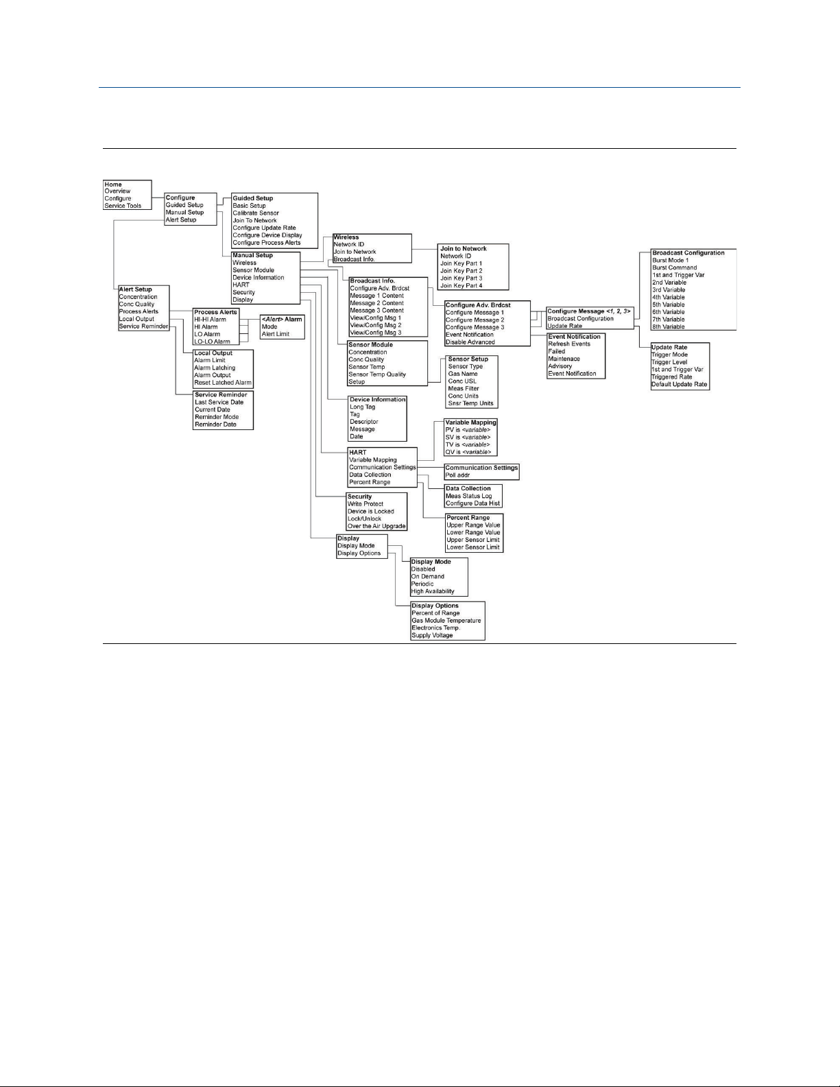
2.6 HART® menu trees
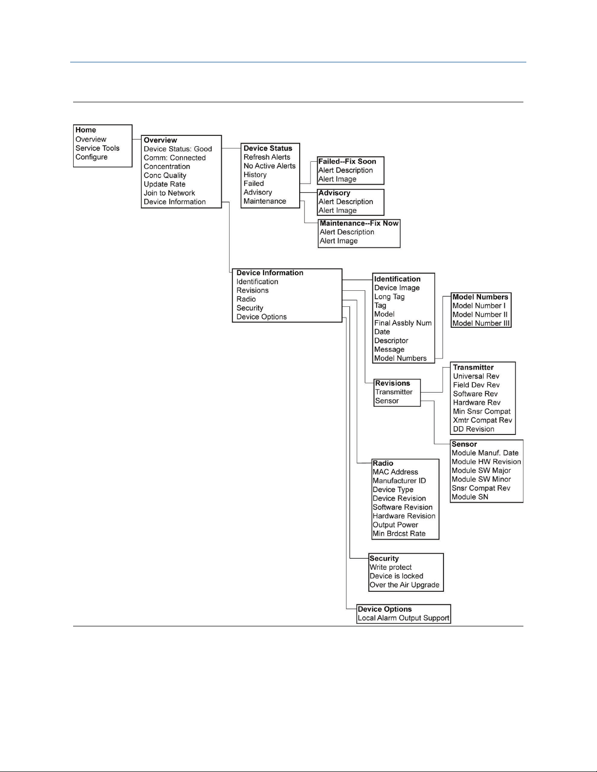
The following figures show the navigation paths for Field Communicator commands and
options. A Rosemount 928 Wireless Gas Monitor DD is required for HART Wireless
transmitter communication. To obtain the latest Emerson DD, visit the System Software
and Device Description web page for your handheld communicator device. Refer to the
reference manual for your handheld communicator device.
Rosemount 928 17
Page 18
Configuration Reference Manual
September 2019 00809-0100-4928
Figure 2-3: Field Communicator Overview Menu Tree
18 Emerson.com/Rosemount
Page 19
Reference Manual Configuration
00809-0100-4928 September 2019
Figure 2-4: Field Communicator Configure Menu Tree
Rosemount 928 19
Page 20
Configuration Reference Manual
September 2019 00809-0100-4928
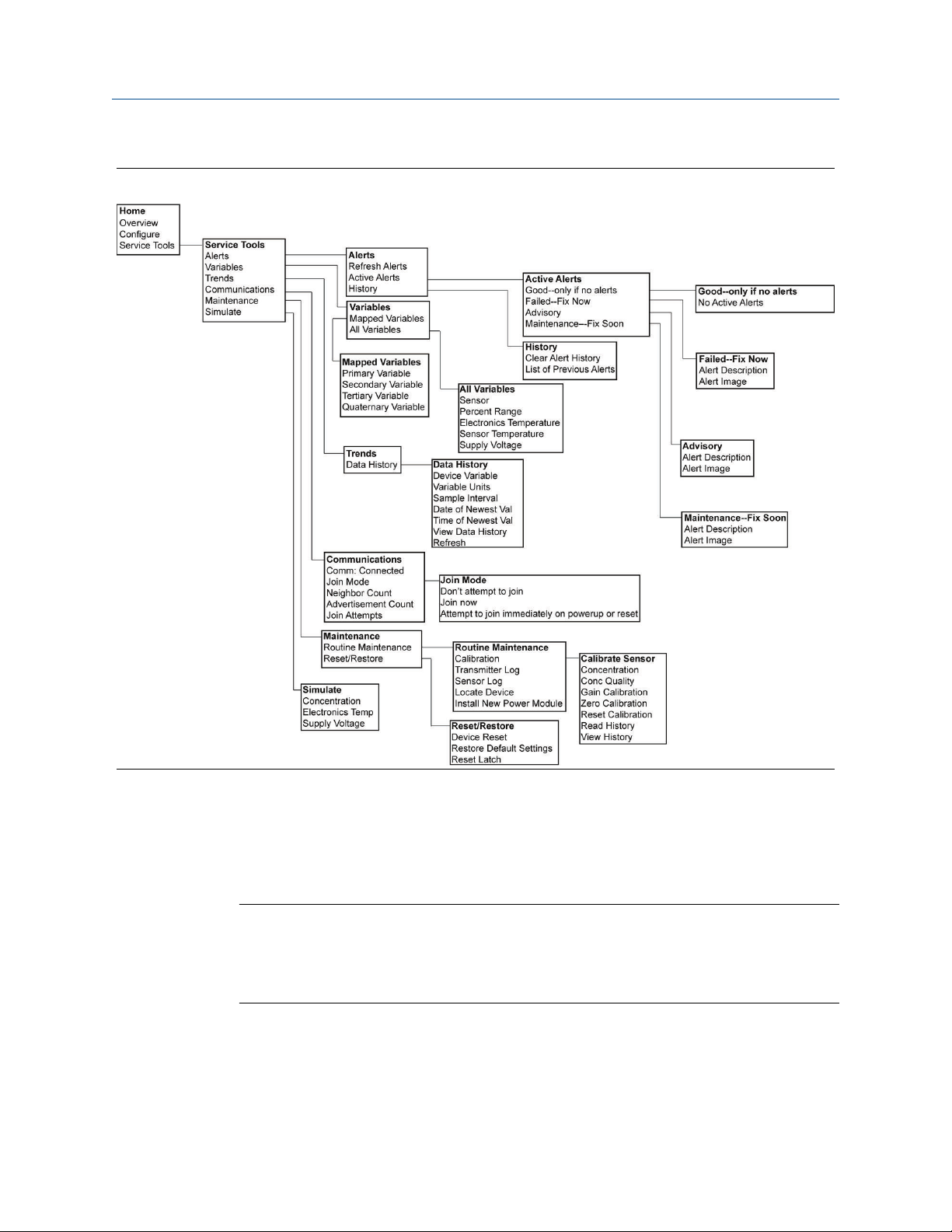
Figure 2-5: Field Communicator Service Tools Menu Tree
2.7 Guided setup
Guided setup contains basic configurations settings. The Guided Setup menus are useful
during initial configuration.
Note
Emerson developed the Field Communicator Guided Setup configuration procedures
using Emerson AMS Trex™ Device Communicator. The menus are identical to those found
in other Field Communicators, but are navigated using touch screens rather than fast keys.
Refer to the manual for your handheld communicator device for more information.
20 Emerson.com/Rosemount
Page 21
Reference Manual Configuration
00809-0100-4928 September 2019
Procedure
1.
WARNING
Explosions
Do not connect to the COMM terminals when an explosive atmopshere is present.
Connect the HART® communication leads to the HART terminals on the handheld
communicator.
2.
WARNING
Explosions
Do not connect to the COMM terminals when an explosive atmopshere is present.
Connect the HART communication leads to the COMM terminals on the transmitter
terminal block.
3. Start your handheld communicator device. If necessary, open the HART Field
Communicator application on your handheld device to establish HART
communication.
Refer to the manual for your handheld communicator device for more information.
4. On the Overview screen, select Configure.
Rosemount 928 21
Page 22
Configuration Reference Manual
September 2019 00809-0100-4928
5. On the Configure screen, select Guided Setup.
6. Perform each of the configuration tasks in the following subsections.
2.7.1
Basic setup
Basic setup using Field Communicator
Procedure
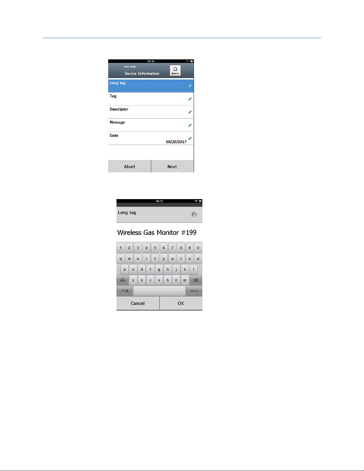
1. On the Guided Setup screen, select Basic Setup.
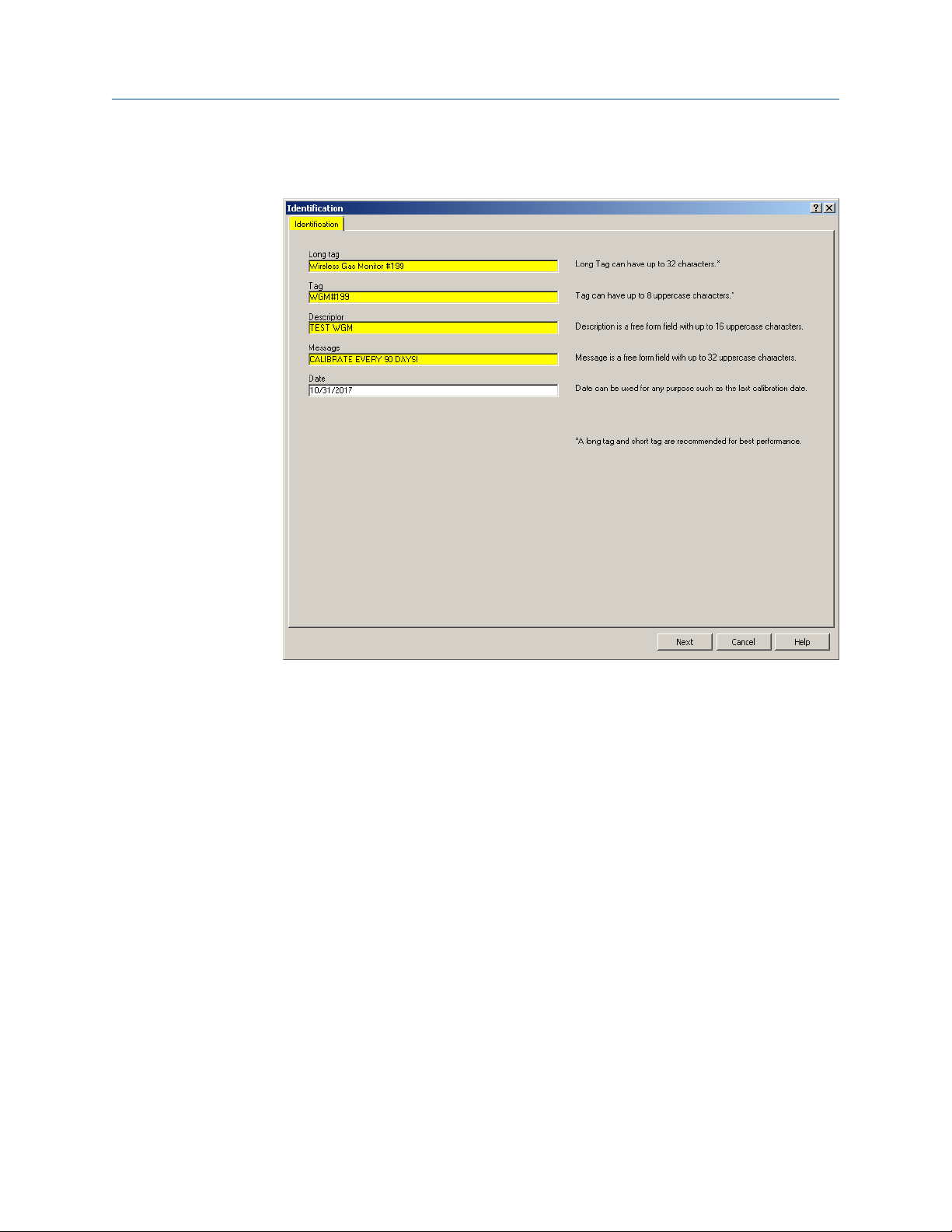
2. On the Device Information screen, select any of the following and configure as
needed. Otherwise, continue with Step 3.
22 Emerson.com/Rosemount
Page 23
Reference Manual Configuration
00809-0100-4928 September 2019
• Long tag: Enter an identifier for the device up to 32 characters long using the
virtual keypad. The Long tag field is blank by default and does not display if left
blank.
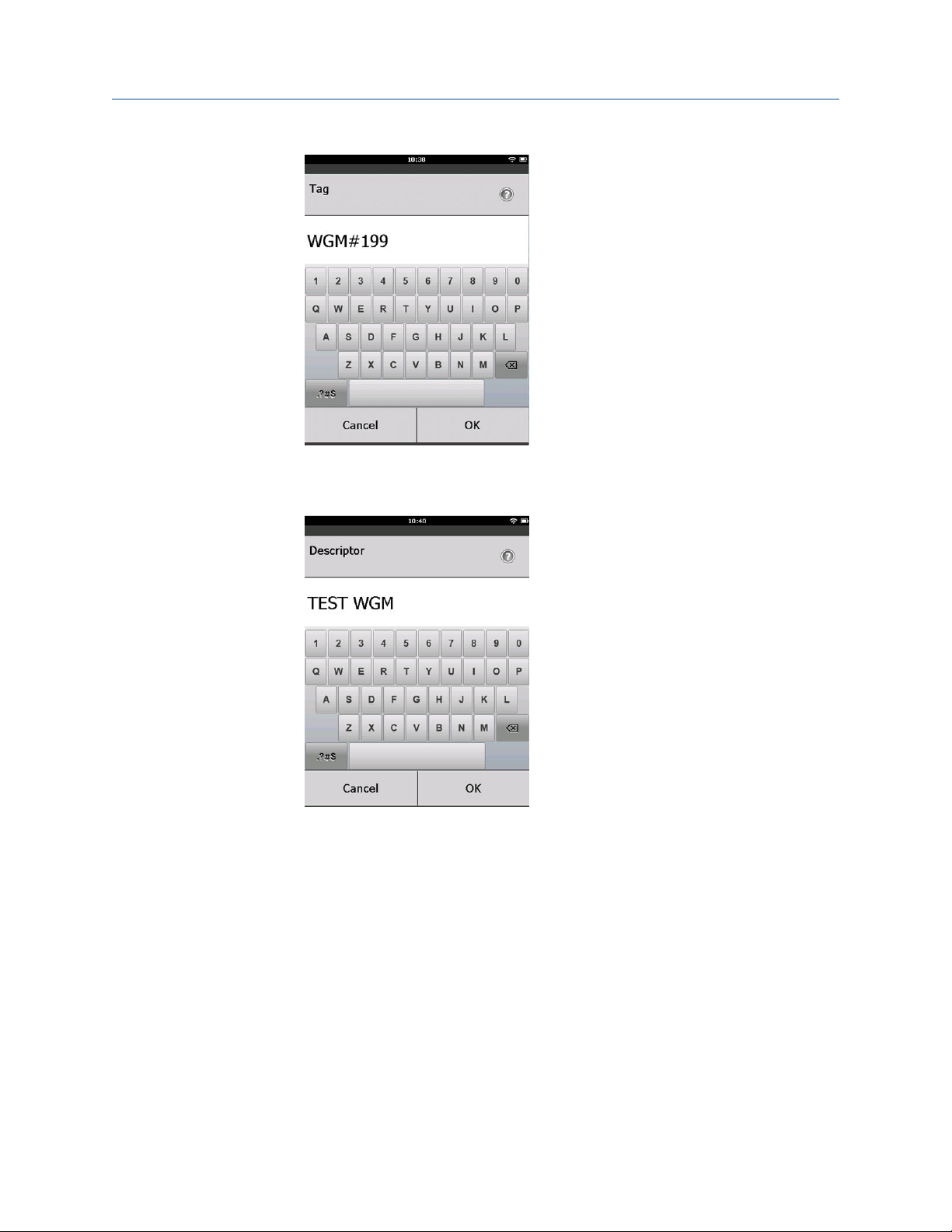
• Tag: Enter an identifier for the device up to eight uppercase alphabetic and
numeric characters long using the virtual keypad. The Tag field is blank by
default and does not display if left blank.
Rosemount 928 23
Page 24
Configuration Reference Manual
September 2019 00809-0100-4928
• Descriptor: Enter a description of the device up to 16 alphabetic, numeric, and
special characters long. The Descriptor field is blank by default and does not
display if left blank.
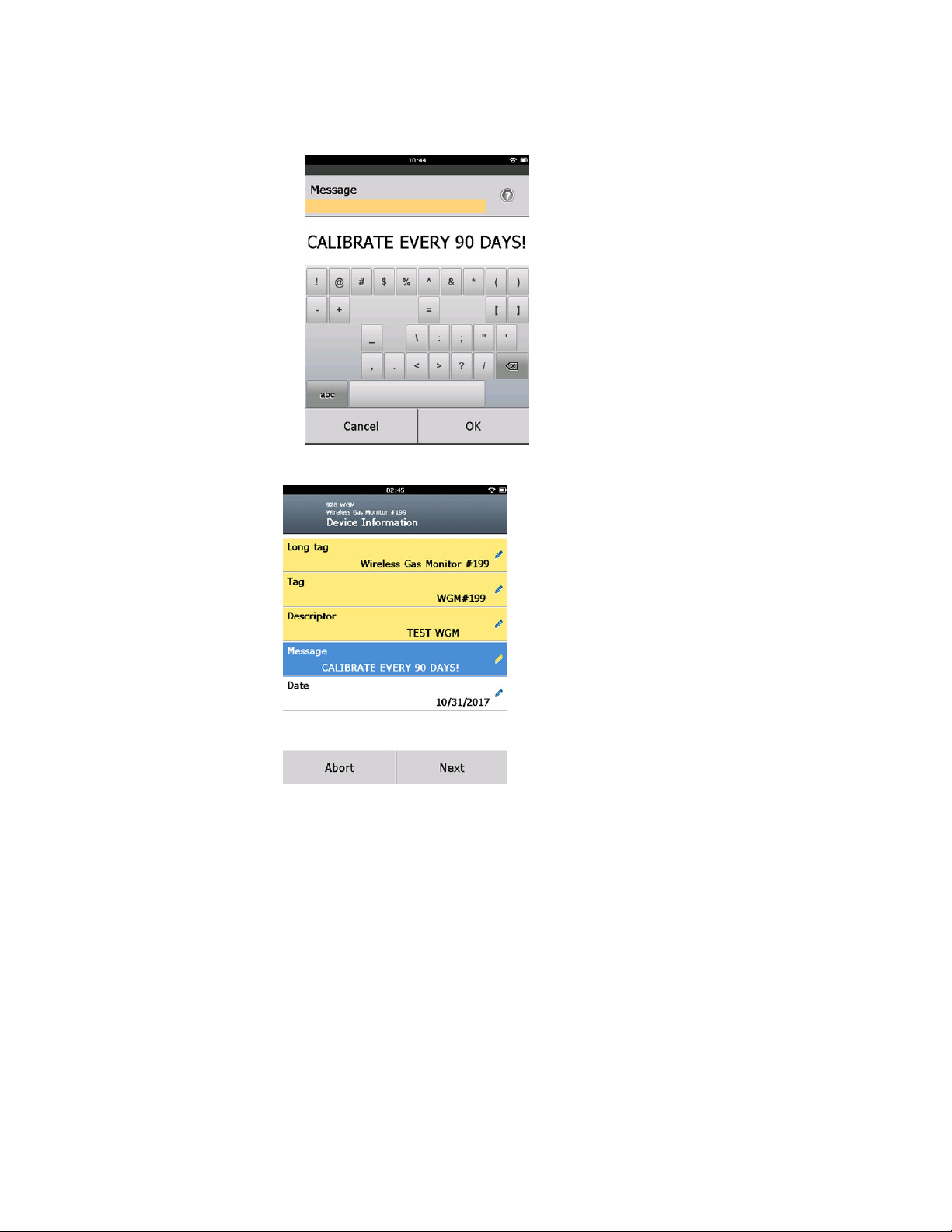
• Message: Enter a message up to 32 alphabetic, numeric, and special characters
long. The Message field is blank by default, does not display if left blank, and
may be used for any purpose.
24 Emerson.com/Rosemount
Page 25
Reference Manual Configuration
00809-0100-4928 September 2019
3. On the Device Information screen, select Next.
Rosemount 928 25
Page 26
Configuration Reference Manual
September 2019 00809-0100-4928
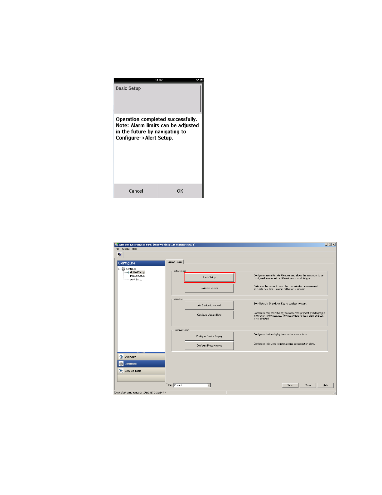
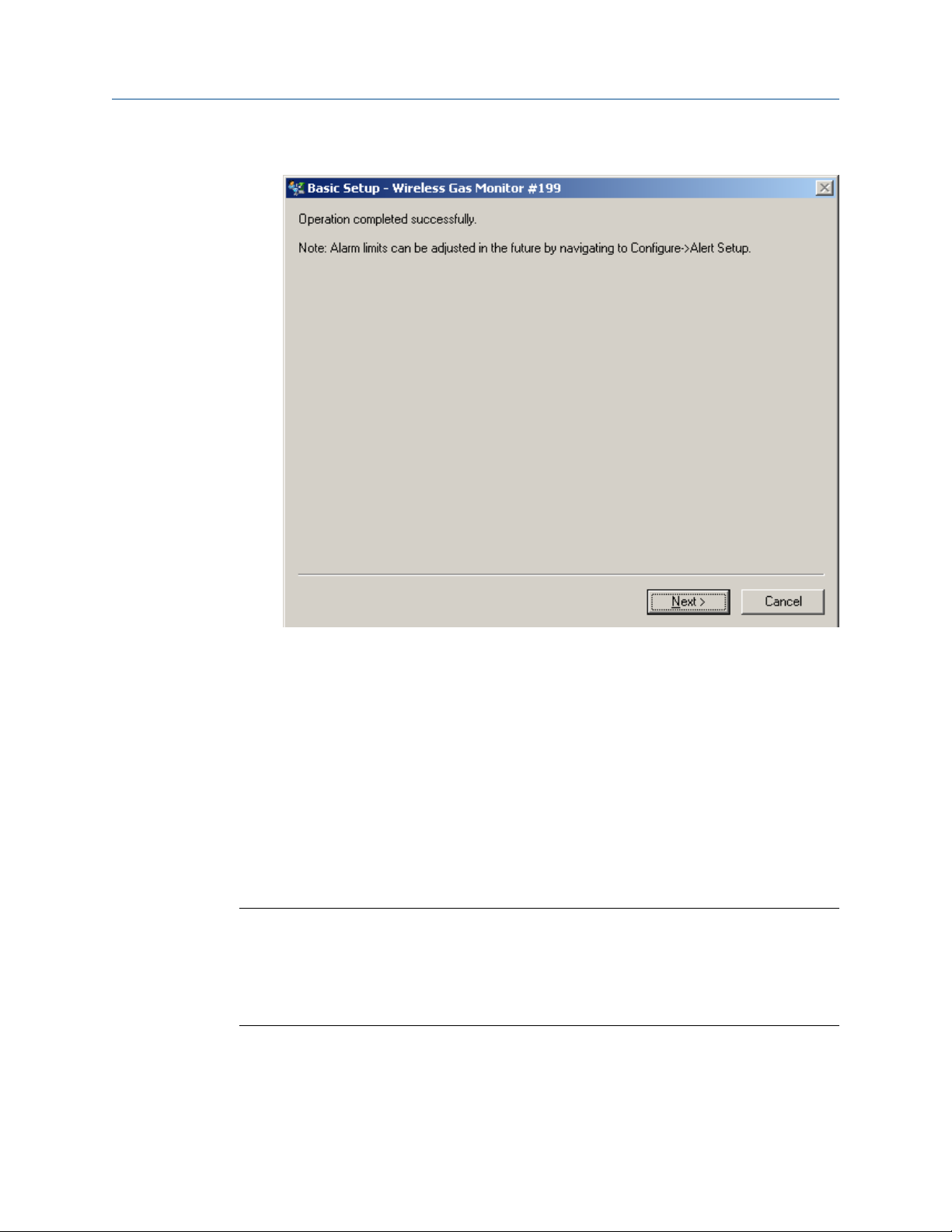
4. On the Basic Setup screen, select OK to confirm successful completion of basic
setup.
Basic setup using AMS Wireless Configurator
Procedure
1. On the Guided Setup tab, in the Initial Setup field, select Basic Setup.
26 Emerson.com/Rosemount
Page 27
Reference Manual Configuration
00809-0100-4928 September 2019
2. On the Device Information tab, configure any of the following as needed.
Otherwise, continue with Step 3.
• Long tag: Enter an identifier for the device up to 32 characters long using the
virtual keypad. The Long tag field is left blank by default and does not display if
left blank.
• Tag: Enter an identifier for the device up to eight uppercase alphabetic and
numeric characters long using the virtual keypad. The Tag field is blank by
default and does not display if left blank.
• Descriptor: Enter a descriptor of the device up to 16 alphabetic, numeric, and
special characters long. The Descriptor field is blank by default and does not
display if left blank.
• Message: Enter a message up to 32 alphabetic, numeric, and special characters
long. The Message field is left blank by default, does not display if left blank, and
may be used for any purpose.
Rosemount 928 27
Page 28
Configuration Reference Manual
September 2019 00809-0100-4928
3. On the Basic Setup screen, select Next.
2.7.2
4. Select Finish.
Joining the transmitter to a wireless network
To communicate with the Wireless Gateway and the host system, you must use the
wireless network to configure the transmitter.
This procedure is the wireless equivalent of connecting wires from a transmitter to the
host system. Using Field Communicator or AMS Wireless Configurator, enter the network
ID and join key so that they match the network ID and join key of the Wireless Gateway
and other devices in the network. If the network ID and join key are not identical, the
transmitter will not communicate with the network. You can obtain the network ID and
join key from the Wireless Gateway on the Setup → Network → Settings page on the web
server.
Note
The amount of time required to join the new device or devices to the network is
dependent on the number of devices being joined and the number of devices in the
current network. One new device joining an existing network with multiple devices may
take up to five minutes. Multiple new devices joining an existing network may take up to
60 minutes.
28 Emerson.com/Rosemount
Page 29
Reference Manual Configuration
00809-0100-4928 September 2019
Join a wireless network using Field Communicator
Procedure
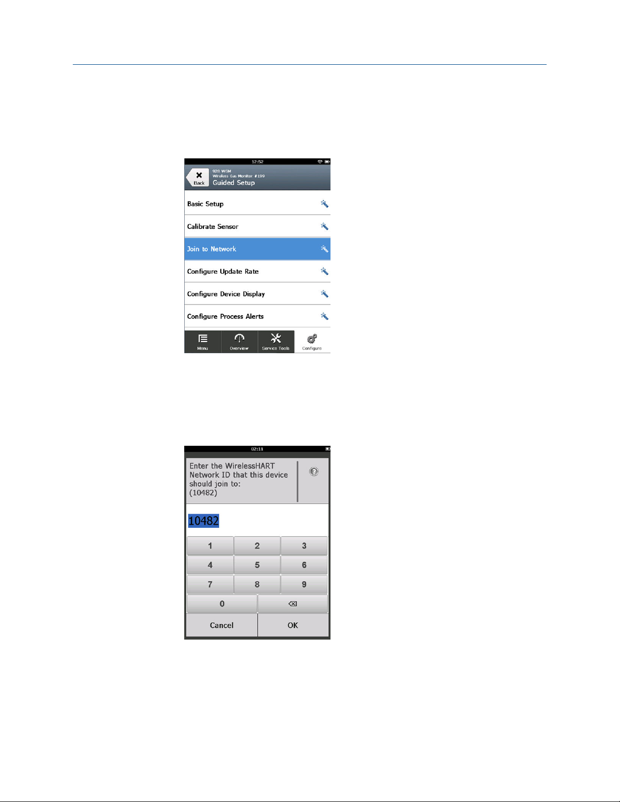
1. On the Guided Setup screen, select Join to Network.
2. On the Join to Network screen, use the numeric keypad to enter the WirelessHART
network ID.
The network ID must match the Wireless Gateway network ID. Refer to the System
Settings → Network → Network Settings page in the Wireless Gateway web-based
user interface for the network ID.
3. Select OK.
®
Rosemount 928 29
Page 30
Configuration Reference Manual
September 2019 00809-0100-4928
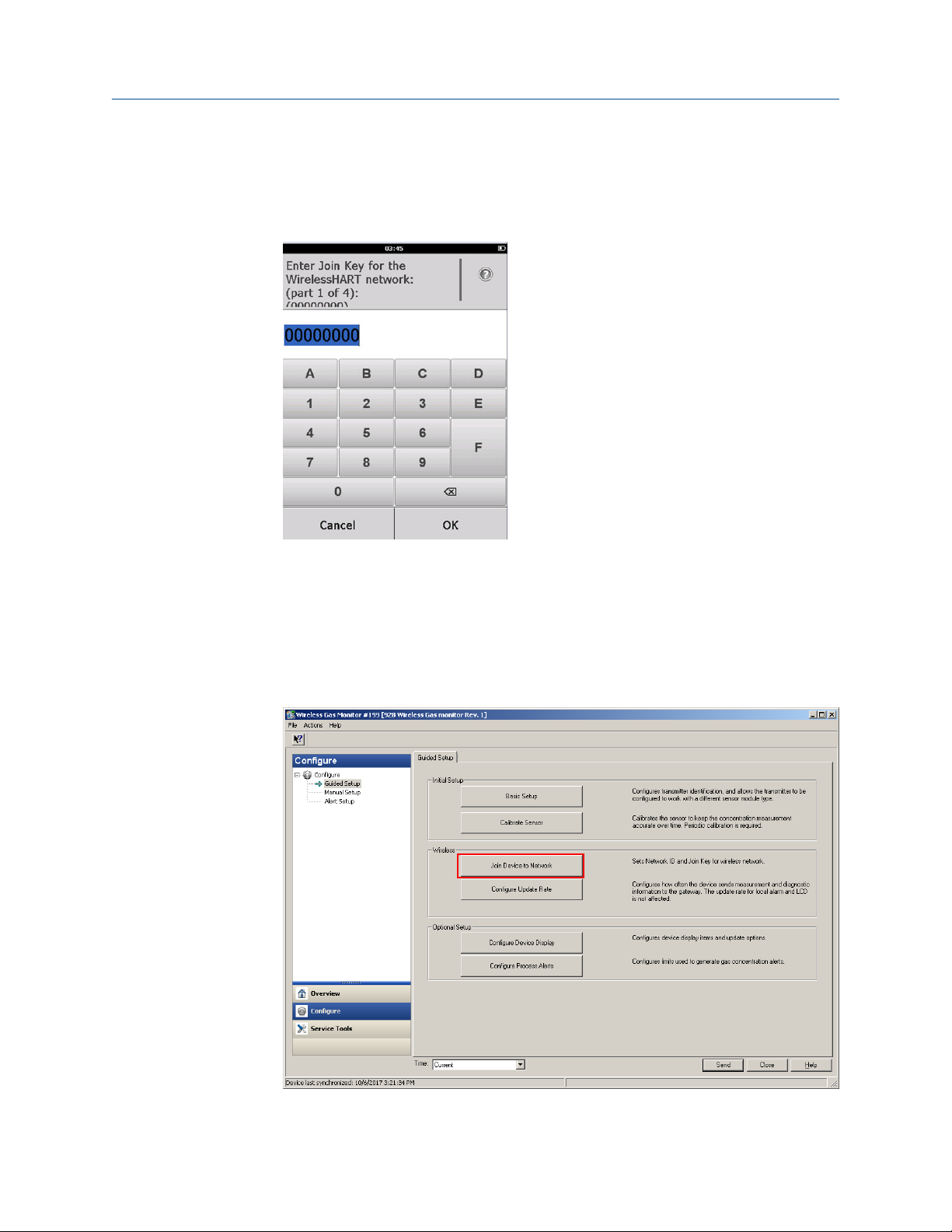
4. On the Join Key screen, use the hexadecimal keypad to enter the first part of the
join key.
Refer to the System Settings → Network → Network Settings page in the Wireless
Gateway web-based user interface for the join key.
5. Select OK.
6. Repeat Step 4 and Step 5 for parts 2 - 4 of the join key.
Join a wireless network using AMS Wireless Configurator
Procedure
1. On the Guided Setup tab, in the Wireless field, select Join Device to Network.
30 Emerson.com/Rosemount
Page 31

Reference Manual Configuration
00809-0100-4928 September 2019
2. On the Join Device to Network tab, enter the network ID and join key.
2.7.3
3. Select Next.
4. Follow the steps in the wizard to complete the network configuration.
Update rate considerations
Before configuring the wireless update rate for your wireless devices, evaluate the safety
concerns, conditions, and wireless network in your facility to select the current update rate
to meet your needs.
When specifying the update rate, consider the potential for toxic gas release, the severity
of potential gas concentration that may be released, and whether the device is located in a
populated area. The default update rate is eight seconds and is appropriate for most
applications. You may use a more frequent update rate if desired. A less frequent update
rate extends transmitter power module life and optimizes Wireless Gateway device
capacity.
Consider the speed with which you want to be alerted to a dangerous condition of toxic
gas. Emerson does not recommend reporting by exception for the Rosemount 928
Wireless Gas Monitors or Emerson Wireless Gateways due to its potential adverse effect on
Wireless Gateway capacity and network integrity. Therefore, select an update rate for all
wireless gas monitors that corresponds to the safety needs of your facility but does not
exceed the capacity of the Wireless Gateway or your wireless network.
Rosemount 928 31
Page 32

Configuration Reference Manual
September 2019 00809-0100-4928
Note
The configured wireless update rate does not affect the LCD display and the optional alarm
output (if installed) update rates.
2.7.4 Configuring the update rate
The Rosemount 928 takes measurements every two seconds. The update rate is the
frequency at which new measurements and device statuses are transmitted over the
wireless network. You may change the update rate during configuration. The update rate
range is one second to sixty minutes. The default update rate is eight seconds. Less
frequent update rates help extend power module life and optimize Wireless Gateway
capacity.
Configure the update rate using Field Communicator
Procedure
1. On the Guided Setup screen, select Configure Update Rate.
2. On the Configure Update Rate screen, do one of the following:
• a. For an update rate from 1 to 60 seconds, select an update rate from the
list.
b. Select OK.
32 Emerson.com/Rosemount
Page 33

Reference Manual Configuration
00809-0100-4928 September 2019
• a. For update rates greater than 60 seconds, select 61-3600 seconds from
the list.
b. Enter the update rate in number of seconds. For example, enter 1800
seconds for 30 minutes.
Rosemount 928 33
Page 34

Configuration Reference Manual
September 2019 00809-0100-4928
c. Select OK.
3. On the Emerson Wireless Gateway Optimizations screen, select Yes - Enable
Optimizations to save and use wireless optimizations or select No - Disable
Optimizations to reject wireless optimizations.
Note
Wireless gateway optimizations combine process measurement and device
diagnostic messages from field devices to the wireless gateway, saving network
bandwidth. If you don't use optimizations, you will need more message packets to
receive the same amount of information. Emerson recommends enabling wireless
gateway optimizations unless they are incompatible with the wireless gateway.
4. Select OK.
5. On the Configure Update Rate screen, select OK to confirm successful update rate
configuration.
34 Emerson.com/Rosemount
Page 35

Reference Manual Configuration
00809-0100-4928 September 2019
Configure the update rate using AMS Wireless Configurator
Procedure
1. On the Guided Setup tab, in the Wireless field, select Configure Update Rate to
configure the frequency at which the device reports measurement and diagnostic
information.
2. On the Configure Update Rate screen, do one of the following:
• a. Select an update rate from 1 to 60 seconds from the list.
b. Select Next.
Rosemount 928 35
Page 36

Configuration Reference Manual
September 2019 00809-0100-4928
• a. Select 61-3600 from the list.
b. Type the number of seconds for an update rate from 61 seconds to 60
minutes. For example, enter 1800 seconds for 30 minutes.
36 Emerson.com/Rosemount
Page 37

Reference Manual Configuration
00809-0100-4928 September 2019
c. Select Next.
3. On the Wireless Gateway Optimization screen, select Yes - Enable Optimizations
to save and use wireless optimizations or select No - Disable Optimizations to reject
wireless optimizations.
Note
Wireless gateway optimizations combine process measurement and device
diagnostic messages from field devices to the wireless gateway, saving network
bandwidth. If you don't use optimizations, you will need more message packets to
receive the same amount of information. Emerson recommends enabling wireless
gateway optimizations unless they are incompatible with the wireless gateway.
4. Select Next.
Rosemount 928 37
Page 38

Configuration Reference Manual
September 2019 00809-0100-4928
5. Select Next and then select Finish to save the update rate configuration.
2.7.5 Configuring the device display mode
The device display mode defines whether or how frequently the LCD display is turned on
to display selected dynamic variables screens. Disabling the display mode or selecting a
less frequent display mode extends power module life.
Configure the device display mode using Field Communicator
Procedure
1. On the Guided Setup screen, select Configure Device Display.
38 Emerson.com/Rosemount
Page 39

Reference Manual Configuration
00809-0100-4928 September 2019
2. On the Device Display Options screen, select one of the following display mode
options.
• Disabled: The display is turned off. This is useful if the display will never be
viewed locally.
• On Demand: The display is on when the gas monitor is connected to a handheld
communication device or when it receives a signal from its wireless gateway.
• Periodic: The display is on only during updates at the configured update rate.
• High Availability: The display is always on regardless of the configured update
rate. This is the default display mode option.
3. Select OK to save the selected device display options.
Note
When a handheld communication device is connected to the transmitter, the LCD display
is in High Availability mode. Selecting and accepting the On Demand or Periodic options
does not take effect until approximately five minutes after the handheld communicator
device is disconnected. Selecting and displaying Disabled takes effect immediately.
Rosemount 928 39
Page 40

Configuration Reference Manual
September 2019 00809-0100-4928
Configure the device display mode using AMS Wireless Configurator
Procedure
1. On the Guided Setup tab, in the Optional Setup field, select Configure Device
Display.
2.7.6
2. Select one of the following display mode options:
• Disabled: The display is turned off. This is useful if the display will never be
viewed locally.
• On Demand: The display is on when the gas monitor is connected to a handheld
communication device or when it receives a signal from its wireless gateway.
• Periodic: The display is on only during updates at the configured update rate.
• High Availability: The display is always on regardless of the configured update
rate. This is the default display mode option.
3. Follow the steps in the wizard to configure the device display mode.
Configuring process alerts
Process alerts allow you to configure the device to send a HART® message when the
configured data point is exceeded. Alerts remain active if the set points are exceeded and
the alert mode is ON. Process alerts are displayed on a handheld communication device,
on the AMS Device Manager status screen, on the Wireless Gateway web interface, on host
systems with which the Wireless Gateway communicates, and in the error section of the
LCD display (if so configured). Disable process alerts if the Rosemount 928 is not
connected to a wireless network.
40 Emerson.com/Rosemount
Page 41

Reference Manual Configuration
00809-0100-4928 September 2019
The gas concentration may be latched. If you select Latch Concentration Alarms, the alarm
output is latched until the alert is manually cleared.
You can reset a latched gas concentration alarm by using Field Communicator or AMS
Wireless Configurator. Refer to Resetting latched alarms for information about clearing
latched local alarms. If you select Not Latched, the gas concentration alarm clears
automatically when the gas concentration level dissipates below the specified High
Concentration Threshold.
You can also clear latched alarms by resetting the alarm by removing and reinstalling the
power module. Refer to Remove power module and Install the power module. Latched
alarms do not remain latched following a device reset or power module failure.
Clearing alert history clears process alert history for other alerts, but does not clear latched
gas concentration alerts. Refer to Clearing process alarm history. You may query alert
history for other process alerts to determine whether they have been active.
Configure process alerts using Field Communicator
Procedure
1. On the Guided Setup screen, select Configure Process Alerts.
Rosemount 928 41
Page 42

Configuration Reference Manual
September 2019 00809-0100-4928
2. On the Process Alerts screen, select a process alert to configure.
3. On the selected process alert screen, select Mode.
42 Emerson.com/Rosemount
Page 43

Reference Manual Configuration
00809-0100-4928 September 2019
4. On the Mode screen, select Enabled.
5. Select OK.
6. On the selected process alert screen, select Alert Limit.
Rosemount 928 43
Page 44

Configuration Reference Manual
September 2019 00809-0100-4928
7. On the Alert Limit screen, use the numeric keypad to enter an alert limit for the
selected process alert based on your needs and local regulations.
8. Select OK.
9. On the selected process alert screen, select Next.
44 Emerson.com/Rosemount
Page 45

Reference Manual Configuration
00809-0100-4928 September 2019
10. On the Configure Process Alerts screen, select OK to confirm successful process
alert configurations.
11. Repeat Step 2 through Step 10 as necessary to configure additional process alerts.
12. When you have completed configuration, remove the HART® communication leads
from the Comm terminals on the terminal block and replace the rear housing cover.
Configure process alerts using AMS Wireless Configurator
Procedure
1. On the Guided Setup tab, in the Optional Setup field, select Configure Process
Alerts.
The Process Alerts window is displayed.
Rosemount 928 45
Page 46

Configuration Reference Manual
September 2019 00809-0100-4928
2. In the Mode list, in the HI-HI Alarm field, select Enabled to enable the alarm.
3. In the Alert Limit box, enter an alert limit for the selected process alert based on
your needs and local regulations.
4. Repeat Step 2 and Step 3 if necessary to configure the Hi Alarm process alert.
5. Select Next.
46 Emerson.com/Rosemount
Page 47

Reference Manual Configuration
00809-0100-4928 September 2019
6. Select Next to confirm successful process alert configuration.
7. Select Finish.
2.8 Calibrating the sensor
Calibrating the sensor ensures that the analog, digital, and discrete outputs accurately
transmit the target gas concentrations registered by the module. Although Emerson
calibrated the device at the factory, you must calibrate it at the following times to ensure
accuracy and correct operation:
• During installation.
• At least every 90 days throughout the device's service life.
• When replacing the sensor.
The Rosemount 628 Universal Gas Sensor is a smart sensor. As such, it retains its own
calibration information. It must be connected to a transmitter to calibrate, but the
calibration settings are stored in the sensor itself rather than in the transmitter. You may
uninstall the sensor from a transmitter and reinstall it in another transmitter without
affecting its calibration.
CAUTION
If you are calibrating in a windy environment (over five mph), a calibration cup must be
used to ensure calibration accuracy.
Rosemount 928 47
Page 48

A
B
Configuration Reference Manual
September 2019 00809-0100-4928
Note
You do not need a conventional calibration cup to calibrate the sensor. Connect
calibration tubing (PVC tubing, 3/16-in. ID, 5/16-in. OD) directly to the fitting on the IP
filter assembly (part number 00628-9000-0001).
2.8.1 Calibrate using Field Communicator
Note
Emerson developed the Field Communicator guided setup configuration procedures in
this manual using Emerson AMS Trex Device Communicator. The menus are identical to
those found in other Field Communicators, but you navigate using touch screens rather
than fast keys. Refer to the manual for your handheld communication device for more
information.
Procedure
1.
WARNING
Explosions
Do not connect to the COMM terminals when an explosive atmosphere is present.
Connect the HART® communication leads from the Field Communicator HART
terminals to the COMM terminals on the terminal block of the transmitter.
A. +COMM terminal
B. -COMM terminal
2. Establish communication between the transmitter and the Field Communicator.
3. On the Home screen, select Configure.
48 Emerson.com/Rosemount
Page 49

Reference Manual Configuration
00809-0100-4928 September 2019
4. On the Configure screen, select Guided Setup.
5. On the Guided Setup screen, select Calibrate Sensor.
Rosemount 928 49
Page 50

Configuration Reference Manual
September 2019 00809-0100-4928
6. Select OK to accept the current date as the calibration date and continue.
7. Acknowledge the warning. If necessary, remove the loop from automatic control.
Note
Calibration of an O2 sensor is unlikely to use a true zero value for its lower limit; one
must calibrate the sensor to a known lower percent oxygen value (such as 15
percent oxygen level by volume) in order to "zero" the sensor as outlined in the
remainder of the calibration steps below.
8. When calibrating for H2S and CO, expose the sensor to clean air to zero the reading.
When calibrating for O2, expose the sensor to a known percent of oxygen content
calibration gas (recommended 15 percent oxygen by volume) to be used as the
"zero" calibration value. If the ambient air may contain trace amounts of target gas
or other gases (for example, carbon monoxide from engine exhaust) that may
interfere with zeroing the device, do the following:
a) Obtain a cylinder of verified clean air (H2S and CO) or a cylinder of verified
percent oxygen content calibration gas (O2) and a length of calibration
tubing (PVC tubing, 3/16-in. ID, 5/16-in. OD).
50 Emerson.com/Rosemount
Page 51

Reference Manual Configuration
00809-0100-4928 September 2019
b) Install a regulator on the clean air/percent known oxygen content gas
cylinder.
c) Attach a length of calibration tubing (PVC tubing, 3/16-in. ID, 5/16-in. OD)
from the regulator on the cylinder to the fitting on the IP filter assembly (part
number 00628-9000-0001).
d) Release the clean air/known percent oxygen specified calibration gas to the
sensor.
Note
If you need a long length of calibration tubing to reach the device, make
allowances for a delay in response time from the sensor while the clean air
travels the length of the calibration tubing.
e) Complete Step 9 through Step 11.
f) Turn off the clean air (or percent oxygen specified calibration gas) when the
sensor is correctly zeroed.
Rosemount 928 51
Page 52

Configuration Reference Manual
September 2019 00809-0100-4928
9. Select OK when the zero measurement reading stabilizes.
Note
Negative measurement readings may occur and are normal during zeroing.
10. Wait while the Field Communicator performs zero adjustment.
52 Emerson.com/Rosemount
Page 53

Reference Manual Configuration
00809-0100-4928 September 2019
11. Select OK to accept the new zero.
12. On the Calibrate Sensor screen, enter a gas concentration level that corresponds to
the concentration of calibration gas that will be applied during calibration.
For oxygen, use 20.9 percent oxygen from clean air. This step may be performed
with surrounding air if no contaminants are present.
13. Select OK.
Rosemount 928 53
Page 54

Configuration Reference Manual
September 2019 00809-0100-4928
14.
WARNING
Toxic gas
Before performing the next step, verify that the regulator is closed to avoid
releasing target gas into the air during calibration.
Install a regulator on the target gas source.
15. Attach a length of calibration tubing (PVC tubing, 3/16-in. ID, 5/16-in. OD) from the
regulator on the target gas source to the fitting on the IP filter assembly (part
number 00628-9000-0001).
54 Emerson.com/Rosemount
Page 55

Reference Manual Configuration
00809-0100-4928 September 2019
16. Release the target gas from the target gas source.
Emerson recommends a flow rate of 1.0 liters per minute to ensure a consistent
sensor reading.
Note
If you need a long length of tubing to reach the device, make allowances for a delay
in response time from the sensor while the target gas travels the length of the
calibration tubing.
A gas concentration should begin to register on the LCD display and gradually
increase to the calibration gas concentration level. The gas concentration level
shown on the device display may not exactly match that shown on the label of the
target gas source.
17. Wait while the gas concentration measurement stabilizes.
Refer to Figure 2-6.
Figure 2-6: Typical Calibration Profile
A. Gas concentration ppm
B. Time (in seconds)
C. Gas concentration measurement has stabilized
Rosemount 928 55
Page 56

Configuration Reference Manual
September 2019 00809-0100-4928
18. Select OK when the gas concentration measurement stabilizes at or near the target
gas concentration level.
19. Wait while the Field Communicator calibrates.
When the calibration process finishes, the Field Communicator displays the new
adjusted reading.
20. Select OK.
Note
If you can't calibrate the sensor, verify that the correct sensor is installed, the
correct target gas is being applied, and the IP filter is not clogged or obstructed. A
sensor that cannot accept a new calibration may have reached the end of its service
life. Replace the sensor and repeat this procedure. Refer to Replace the gas sensor.
56 Emerson.com/Rosemount
Page 57

Reference Manual Configuration
00809-0100-4928 September 2019
21. Select Accept calibration and then select OK.
The Field Communicator displays the Service Reminder screen if a service reminder
is configured and enabled.
22. Select OK to accept the service reminder date or enter another date.
Refer to Service reminders for more information.
23. Shut off the target gas flow at the regulator.
24. Detach the calibration tubing from the regulator on the target gas source and from
the IP filter inlet on the bottom of the sensor.
Rosemount 928 57
Page 58

Configuration Reference Manual
September 2019 00809-0100-4928
2.8.2 Calibrate using AMS Wireless Configurator
Procedure
1. On the Guided Setup tab, in the Initial Setup field, select Calibrate Sensor.
58 Emerson.com/Rosemount
Page 59

Reference Manual Configuration
00809-0100-4928 September 2019
2. On the Calibrate Sensor screen, select Next to accept the current date as the
calibration date and continue.
Rosemount 928 59
Page 60

Configuration Reference Manual
September 2019 00809-0100-4928
3. On the Warning screen, select Next.
4. When calibrating for H2S, and CO, expose the sensor to clean air to zero the
reading. When calibrating for O2, expose the sensor to a known percent oxygen
content calibration gas (recommended 15 percent oxygen by volume) to be used as
the "zero" calibration value. If the ambient air may contain trace amounts of target
gas or other gases (for example, carbon monoxide from engine exhaust) that may
interfere with zeroing the device, do the following:
a) Obtain a cylinder of verified clean air (H2S and CO) or a cylinder of verified
percent oxygen content calibration gas (O2) and a length of calibration
tubing (PVC tubing, 3/16-in. ID, 5/16-in. OD).
60 Emerson.com/Rosemount
Page 61

Reference Manual Configuration
00809-0100-4928 September 2019
b) Install a regulator on the clean air/known percent oxygen content gas
cylinder.
c) Attach a length of calibration tubing (PVC tubing, 3/16-in. OD, 5/16-in. OD)
from the regulator on the cylinder to the IP filter on the bottom of the sensor.
d) Release the clean air/known percent oxygen specified calibration gas to the
sensor.
Note
If you need a long length of calibration tubing to reach the device, make
allowances for a delay in response time from the sensor while the clean air
travels the length of the calibration tubing.
e) Perform Step 5 through Step 7.
f) Turn off the clean air/known percent oxygen specified calibration gas when
the sensor is correctly zeroed.
Rosemount 928 61
Page 62

Configuration Reference Manual
September 2019 00809-0100-4928
5. Select Next when the zero measurement reading stabilizes.
6. Select Next.
62 Emerson.com/Rosemount
Page 63

Reference Manual Configuration
00809-0100-4928 September 2019
7. Select Accept New Zero.
8. Select Next.
Rosemount 928 63
Page 64

Configuration Reference Manual
September 2019 00809-0100-4928
9. On the Calibrate Sensor screen, enter a gas concentration level.
10. Select Next.
WARNING
Toxic gas
The regulator may release gas into the air during calibration.
Before starting the next step, verify that the regulator is closed.
64 Emerson.com/Rosemount
Page 65

Reference Manual Configuration
00809-0100-4928 September 2019
11. Install a regulator on the target gas source.
12. Attach a length of calibration tubing (PVC tubing, 3/16-in. ID, 5/16-in. OD) from the
regulator on the target gas source to the IP filter inlet on the bottom of the sensor.
Rosemount 928 65
Page 66

Configuration Reference Manual
September 2019 00809-0100-4928
13. Release the target gas from the target gas source.
Emerson recommends a flow rate of 1.0 liters per minute to ensure a consistent
sensor reading.
Note
If you need a long length of calibration tubing to reach the device, make allowances
for a delay in response time from the sensor while the target gas travels the length
of the calibration tubing.
A gas concentration should begin to register on the device display and gradually
increase to the calibration gas concentration level. The gas concentration level
shown on the device display may not exactly match that shown on the label
attached to the target gas source.
14. Wait while the gas concentration measurement stabilizes.
Refer to Figure 2-7.
Figure 2-7: Typical Calibration Profile
A. Gas concentration ppm
B. Time (in seconds)
C. Gas concentration measurement has stabilized
66 Emerson.com/Rosemount
Page 67

Reference Manual Configuration
00809-0100-4928 September 2019
15. Select Next when the gas concentration measurement stabilizes at or near the
target gas concentration level.
Rosemount 928 67
Page 68

Configuration Reference Manual
September 2019 00809-0100-4928
16. Wait while the AMS Wireless Configurator calibrates.
When the calibration process finishes, the new adjusted reading is displayed.
17. Select Next.
68 Emerson.com/Rosemount
Page 69

Reference Manual Configuration
00809-0100-4928 September 2019
18. Select Accept calibration.
Rosemount 928 69
Page 70

Configuration Reference Manual
September 2019 00809-0100-4928
19. Select Next.
The Service Reminder screen is displayed if a service reminder is configured and
enabled.
20. Select Next to accept the service reminder date or enter another date.
Refer to Service reminders for more information.
21. When the gas concentration reading stabilizes at or near the target gas
concentration level, shut off the target gas flow at the regulator.
22. Detach the calibration tubing from the regulator on the target gas source and from
the IP filter inlet on the bottom of the sensor.
2.9 Manual setup
Manual setup includes all available configuration settings. You may use it to change
specific settings configured during initial setup without using the Guided Setup menus.
You may also use it to configure advanced optional settings.
Note
Emerson developed the Field Communicator manual setup configuration procedures in
this manual using Emerson AMS Trex Device Communicator. The menus are identical to
those found in other Field Communicators, but are navigated using touch screens rather
than fast keys. Refer to the manual for your handheld communicator device for more
information.
70 Emerson.com/Rosemount
Page 71

Reference Manual Configuration
00809-0100-4928 September 2019
Procedure
1. Connect the HART® communications leads to the HART terminals on the handheld
communicator.
A. +COMM terminal
B. -COMM terminal
2.
WARNING
Explosions
Do not connect to the COMM terminals when an explosive atmosphere is present.
Connect the HART communication leads to the COMM terminals on the terminal
block.
3. Start your handheld communicator device. If necessary, open the HART Field
Communicator on your handheld device to establish HART communication.
Refer to the manual for your handheld communicator device for more information.
Rosemount 928 71
Page 72

Configuration Reference Manual
September 2019 00809-0100-4928
4. On the Overview screen, select Configure.
5. On the Configure screen, select Manual Setup.
Postrequisites
Perform the configuration tasks in the following subsections as needed.
2.9.1
72 Emerson.com/Rosemount
Configuring display options
The primary variable (gas concentration) is displayed by default on the LCD display.
To configure the display of additional dynamic variable items, do the following:
Page 73

Reference Manual Configuration
00809-0100-4928 September 2019
Configure display options using Field Communicator
Procedure
1. On the Manual Setup screen, select Display.
2. On the Display screen, select Display Options.
Rosemount 928 73
Page 74

Configuration Reference Manual
September 2019 00809-0100-4928
3. Select a display option or options to alternate displaying with the primary variable
(gas concentration):
• Concentration
• Percent of Range
• Sensor Temp (gas sensor module temperature)
• Electronics Temp (electronics temperature)
• Supply Voltage
4. Select On.
5. Select OK.
6. Repeat Step 3 through Step 5 for additional display options.
74 Emerson.com/Rosemount
Page 75

Reference Manual Configuration
00809-0100-4928 September 2019
7. On the Display Options screen, select Send.
8. On the Send screen, do one or more of the following:
• Select Display Options if you want to review the selected display options.
• Select Cancel to return to the Display Options screen. Pending changes to
display options are preserved.
• Select Discard to return to the Display Options screen and discard pending
changes. Select OK to confirm or Cancel to return to the previous screen.
• Select Send to send display option changes to the device.
9. Select Back to return to the Manual Setup screen.
Rosemount 928 75
Page 76

Configuration Reference Manual
September 2019 00809-0100-4928
Configure display options using AMS Wireless Configurator
Procedure
1. On the Manual Setup page, select the Display tab.
2. On the Display tab, select a display option or options to alternate displaying with
the primary variable (gas concentrations).
• Concentration
• Percent of Range
• Sensor Temperature (gas sensor module temperature)
• Electronics Temperature
• Supply Voltage
3. Select Send.
76 Emerson.com/Rosemount
Page 77

Reference Manual Configuration
00809-0100-4928 September 2019
4. In the Confirm Device Configuration Change dialog box, select a reason for the
change from the Service Reason list. Select Details if you want to view additional
information.
5. Select Yes.
Rosemount 928 77
Page 78

Configuration Reference Manual
September 2019 00809-0100-4928
2.9.2 Configuring security settings
You have the option to configure security settings to protect the device from
unauthorized configuration changes.
Configure security settings using a Field Communicator
Procedure
1. On the Manual Setup screen, select Security.
2. Configure the following security settings as required.
• Write Protect: If you select No (the default option), you may view and edit device
configuration settings. If you select Yes, you may view device configuration
settings but not edit them.
• Lock Device: If you select Unlock, you may access the device with any host to
view and edit configuration settings. If you select Lock (the default option), you
cannot access the device with any host to view and edit configuration settings
until a host unlocks the device. To change this option, do the following:
78 Emerson.com/Rosemount
Page 79

Reference Manual Configuration
00809-0100-4928 September 2019
a. On the Security screen, select Lock/Unlock.
b. On the Select HART Lock option screen, select Lock or Unlock to change
the setting.
c. Select OK.
On the Security screen, the Device is Locked field displays On when the device is
locked and Off when the device is unlocked.
• Over the Air Upgrade: If you select Unlock (the default option), you can upgrade
the transmitter radio with programming sent over the air. If you select Lock, the
transmitter prevents over-the-air radio upgrades.
Rosemount 928 79
Page 80

Configuration Reference Manual
September 2019 00809-0100-4928
Configure security settings using AMS Wireless Configurator
Procedure
1. On the Manual Setup page, select the Security tab.
2. Configure the following security settings as needed:
• Write Protection: If you select No (the default option) you can view and edit
device configuration settings. If you select Yes, you will not be able to view and
edit the configuration settings.
• Radio Upgrade: If you select Unlock (the default option), you can upgrade the
transmitter radio with programming sent over the air. If you select Lock, you will
not be able to upgrade the radio over the air.
• Lock Device: If you select Unlock (the default option), you can access the device
with any host to view and edit configuration settings. If you select Lock, you will
not be able to access the device with any host to view and edit configuration
settings until a host unlocks the device. To change this option, do the following:
a. Select Lock/Unlock.
b. In the HART Lock list, select Lock or Unlock to change the setting.
80 Emerson.com/Rosemount
Page 81

Reference Manual Configuration
00809-0100-4928 September 2019
c. Select Finish.
In the HART Lock field, the Device is Locked check box is selected when the
device is locked.
3. When you are finished making changes, select Send to update the device
configuration.
Rosemount 928 81
Page 82

Configuration Reference Manual
September 2019 00809-0100-4928
2.9.3 Configuring device information
Configure device information using Field Communicator
Procedure
1. On the Manual Setup screen, select Device Information.
2. On the Device Information screen, select any of the following and configure as
needed.
• Long tag: Enter an identifier for the device up to 32 characters long using the
virtual keypad. The Long tag field is blank by default and does not display if left
blank.
• Tag: Enter an identifier for the device up to eight uppercase alphabetic and
numeric characters long using the virtual keypad. The Tag field is left blank by
default and does not display if left blank.
82 Emerson.com/Rosemount
Page 83

Reference Manual Configuration
00809-0100-4928 September 2019
• Descriptor: Enter a description of the device up to 16 alphabetic, numeric, and
special characters long. The Descriptor field is blank by default and does not
display if left blank.
• Message: Enter a message up to 32 alphabetic, numeric, and special characters
long. The Message field is blank by default, does not display if left blank, and
may be used for any purpose.
• Date: Enter a date in mm/dd/yyy format using the virtual keypad. The date may
be used for any purpose, such as recording the date of the most recent
calibration.
Rosemount 928 83
Page 84

Configuration Reference Manual
September 2019 00809-0100-4928
3. When you have finished making changes, select Send.
4. On the Send screen, do one of the following:
84 Emerson.com/Rosemount
Page 85

Reference Manual Configuration
00809-0100-4928 September 2019
• Select Cancel to return to the Device Information screen. Pending changes are
preserved.
• Select Discard to return to the Device Information screen and discard pending
changes. Select OK to confirm or Cancel to return to the previous screen.
• Select Send to send display option changes to the device.
5. Select Back to return to the Manual Setup screen.
Configure device information using AMS Wireless Configurator
Procedure
1. On the Manual Setup page, select the Device Information tab.
Rosemount 928 85
Page 86

Configuration Reference Manual
September 2019 00809-0100-4928
2. Enter any of the following as needed:
• Long tag: Enter an identifier for the device up to 32 characters long. The Long
Tag field is blank by default and does not display if left blank.
• Tag: Enter an identifier for the device up to eight uppercase alphabetic and
numeric characters long. The Tag field is blank by default and does not display if
left blank.
• Descriptor: Enter a description of the device up to 16 characters long. The
Descriptor field is blank by default and does not display if left blank.
• Message: Enter text up to 32 characters long. The Message field is blank by
default, does not display if left blank, and may be used for any purpose.
• Date: Enter a date in mm/dd/yyyy format. The date may be used for any
purpose, such as recording the date of the most recent calibration.
3. When you have finished making changes, select Send to update the device
configuration.
2.10 Advanced options
The following optional, advanced functionality is available to view calibration history for
the sensor, set reminders to perform maintenance at regular intervals, and to reset or
restore device settings.
2.10.1
86 Emerson.com/Rosemount
Service reminders
You can configure service reminders for regular maintenance tasks such as calibration,
bump testing, power module replacement, and sensor replacement. The device issues an
Page 87

Reference Manual Configuration
00809-0100-4928 September 2019
alert when the current date is after the configured service date. You may enable or disable
service reminders.
Service reminders are not recurring. For example, if you create a service reminder to
recalibrate the sensor in 90 days, you must create a new reminder for the next service
interval by configuring a new service date. The transmitter must be connected to a
wireless network to accurately maintain the current date.
Configure service reminders using Field Communicator
Procedure
1. On the Overview screen, select Configure.
2. On the Configure screen, select Alert Setup.
Rosemount 928 87
Page 88

Configuration Reference Manual
September 2019 00809-0100-4928
3. On the Alert screen, select Service Reminder.
4. On the Service Reminder screen, select Last Service Date.
88 Emerson.com/Rosemount
Page 89

Reference Manual Configuration
00809-0100-4928 September 2019
5. On the Last Service Date screen, use the numeric keypad to enter the date on
which the last service was performed.
6. Select OK.
7. On the Service Reminder screen, select Reminder Mode.
Rosemount 928 89
Page 90

Configuration Reference Manual
September 2019 00809-0100-4928
8. On the Reminder Mode screen, do one of the following:
• Select Disabled to disable the service reminder.
• Select Enabled to enable the service reminder.
9. Select OK.
10. On the Service Reminder screen, select Reminder Date.
11. On the Reminder Date screen, use the numeric keypad to enter the date when the
next service is due.
12. Select OK.
13. When you are finished, select Send to implement configuration changes.
90 Emerson.com/Rosemount
Page 91

Reference Manual Configuration
00809-0100-4928 September 2019
Configure service reminders using AMS Wireless Configurator
Procedure
1. In the Overview pane, select Configure.
2. On the Configure pane, select Alert Setup.
Rosemount 928 91
Page 92

Configuration Reference Manual
September 2019 00809-0100-4928
3. On the Alert Setup page, select the Service Reminder tab.
4. In the Service Reminder Mode list, do one of the following:
• Select Disabled to disable the service reminder.
• Select Enabled to enable the service reminder.
5. In the Last Recorded Service Date field, enter the date on which the last service was
performed.
6. In the Service Reminder Date field, enter the date when the next service is due.
92 Emerson.com/Rosemount
Page 93

Reference Manual Configuration
00809-0100-4928 September 2019
7. Select Send.
8. In the Confirm Device Configuration Change dialog box, select a reason from the
Service Reason list. Select Details if you want to view additional information.
2.10.2
9. Select Yes.
Reset or restore device settings
Reset or restore device settings using Field Communicator
Procedure
1. On the Overview screen, select Service Tools.
Rosemount 928 93
Page 94

Configuration Reference Manual
September 2019 00809-0100-4928
2. On the Service Tools screen, select Maintenance.
3. On the Maintenance screen, select Reset/Restore.
94 Emerson.com/Rosemount
Page 95

Reference Manual Configuration
00809-0100-4928 September 2019
4. On the Reset/Restore screen, select one of the following:
• Select Device reset to reset the transmitter electronics. This preserves current
user configuration settings.
• Select Restore Default Settings to return the monitor, including the currently
installed sensor, to its factory default settings. This deletes user configuration
settings.
Rosemount 928 95
Page 96

Configuration Reference Manual
September 2019 00809-0100-4928
5. Do one of the following:
• Select Cancel to retain the current settings.
• Select Continue to reset configuration settings or to restore factory default
settings.
• Select OK to continue.
• Select Cancel to return to the previous screen without making changes.
96 Emerson.com/Rosemount
Page 97

Reference Manual Configuration
00809-0100-4928 September 2019
Reset or restore device settings using AMS Wireless Configurator
Procedure
1. In the Overview pane, select Service Tools.
2. In the Service Tools pane, select Maintenance.
Rosemount 928 97
Page 98

Configuration Reference Manual
September 2019 00809-0100-4928
3. Select the Reset/Restore tab.
4. Do one of the following:
• Select Device reset to reset the transmitter electronics. This preserves current
user configuration settings.
• Select Restore Default Settings to return the monitor, including the currently
installed sensor, to its factory default settings. This deletes user configuration
settings.
5. Follow the steps in the wizard to reset the device or restore factory default settings.
98 Emerson.com/Rosemount
Page 99

Reference Manual Configuration
00809-0100-4928 September 2019
2.10.3 Configuring local alarm output
If an external device is connected to the transmitter, you can also configure local alarm
output options.
Configure local alarm output using a Field Communicator
Complete the following steps to configure local alarm output options using a Field
Communicator.
Procedure
1. On the Overview screen, select Configure.
2. On the Configure screen, select Alert Setup.
Rosemount 928 99
Page 100

Configuration Reference Manual
September 2019 00809-0100-4928
3. On the Alert Setup screen, select Local Output.
4. On the Local Output screen, select Alarm Limit.
100 Emerson.com/Rosemount
 Loading...