

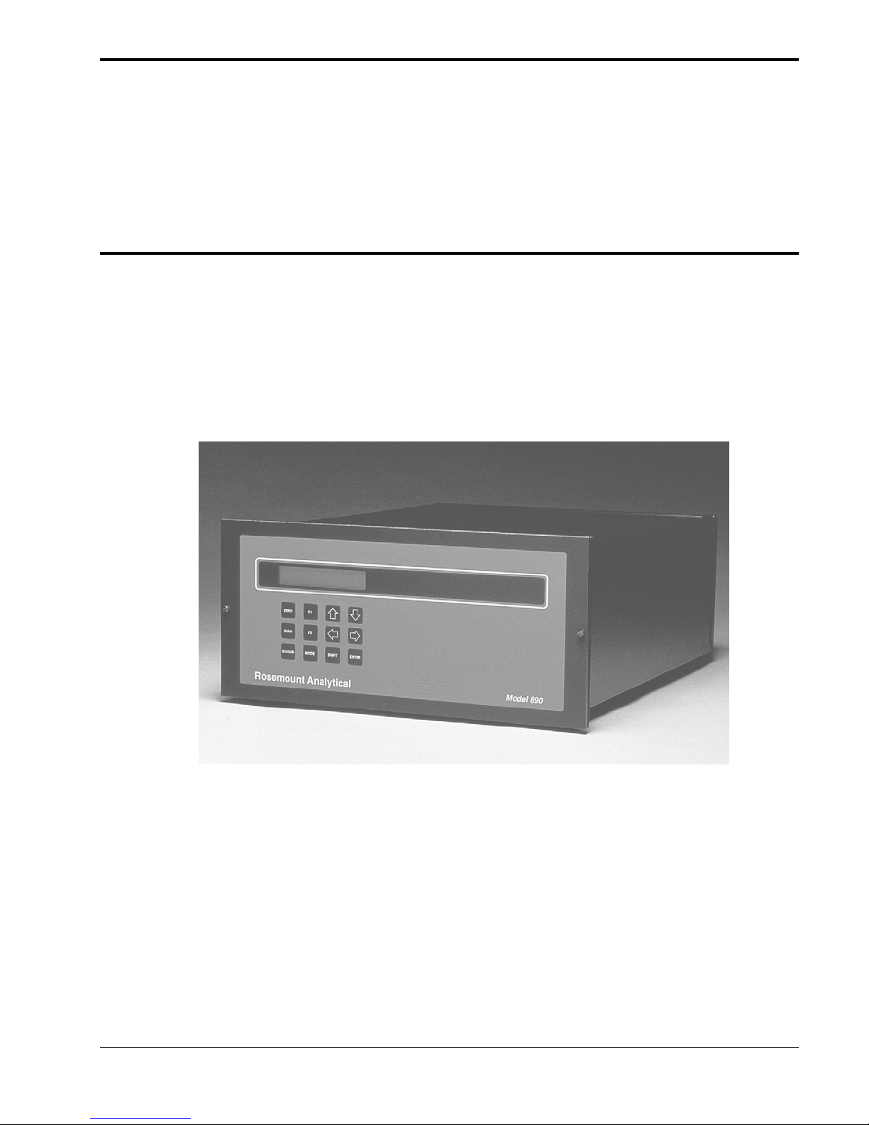
Rosemount 890 Instruction Manual

Rosemount Analytical
M
ODEL
UV A
I
NSTRUCTION MANUAL
NALYZER
748460-A
890

N
OTICE
The information contained in this document is subject to change without notice.
Teflon® and Viton® are registered trademarks of E.I. duPont de Nemours and Co., Inc.
Suprasil II® is a registered trademark of Heraeus Amersil Inc.
Pyrex® is a registered trademark of Corning Glass Works.
SNOOP® is a registered trademark of NUPRO Co.
Manual Part Number 748460-A
January 2000
Printed in U.S.A.
Rosemount Analytical Inc.
4125 East La Palma Avenue
Anaheim, California 92807-1802

ONTENTS
C
REFACE
P
Safety Summary.................................................................................................P-1
Specifications - General......................................................................................P-4
Specifications - Sample......................................................................................P-4
Specifications - Physical.....................................................................................P-5
Specifications - Options...................................................................................... P-5
Customer Service, Technical Assistance and Field Service...............................P-6
Returning Parts to the Factory............................................................................P-6
Training ......................................................................................................P-6
Documentation....................................................................................................P-6
Compliances ......................................................................................................P-7
ECTION
S
1.1 General Description..................................................................................1-1
1.2 Available Options......................................................................................1-3
ECTION
S
2.1 Check for Shipping Damage.....................................................................2-1
2.2 Location....................................................................................................2-1
2.3 Voltage Requirements..............................................................................2-1
2.4 Electrical Connections..............................................................................2-2
2.4.1 Line Power Connections.............................................................2-2
2.4.2 Recorder Connections ................................................................2-3
2.5 SAMPLE INLET/OUTLET CONNECTIONS..............................................2-4
2.6 CALIBRATION GAS REQUIREMENTS ...................................................2-5
2.7 SAMPLE HANDLING SYSTEM................................................................2-5
2.8 LEAK TEST PROCEDURE.......................................................................2-5
2.9 SAMPLE FLOW RATE.............................................................................2-6
2.10 OPTION BOARDS....................................................................................2-6
2.10.1 Alarm Connections....................................................................2-7
2.10.2 Calibration and Gas Control Connections.................................2-7
2.10.3 Auto Zero/Span Connections....................................................2-8
NTRODUCTION
1. I
2. U
NPACKING AND INSTALLATION
748460-A
January 2000
Rosemount Analytical
I

C
ONTENTS
2.10.4 Remote Input/Output Connections ........................................... 2-9
2.11 Ordering Option Kits............................................................................... 2-10
ECTION
S
3.1 Leak Test ................................................................................................. 3-1
3.2 Power Verification.................................................................................... 3-1
3.3 Software/Countdown................................................................................ 3-2
3.4 Front Panel Indicators and Controls......................................................... 3-2
3.4.1 Display ..................................................................................... 3-2
3.4.2 Function Keys............................................................................. 3-2
3.4.3 User Programmable Keys .......................................................... 3-4
3.4.4 Run Mode Display...................................................................... 3-5
3.4.5 General Display Information....................................................... 3-5
3.5 Accessing Mode Displays ........................................................................ 3-6
3.6 Security Code........................................................................................... 3-8
3.7 Range Parameters................................................................................... 3-9
3.8 Analyzer Diagnostics................................................................................ 3-11
3.9 Zero Calibration........................................................................................ 3-11
3.10 Zero Calibration for the Analyzer with the Calibration Gas
3.11 Span Calibration....................................................................................... 3-13
3.12 Span Calibration for the Analyzer with the Calibration Gas
3.13 Linearization............................................................................................. 3-14
3.14 Alarm ...................................................................................................... 3-19
3.14.1 STATUS Display....................................................................... 3-21
3.15 Current Output ......................................................................................... 3-22
3.16 Auto Zero/Span Option ............................................................................ 3-22
3.17 Remote Range input/Output Option......................................................... 3-26
3.18 Interference Balance................................................................................ 3-28
NITIAL STARTUP AND CALIBRATION
3. I
Control Option .............................................................................. 3-13
Control Option .............................................................................. 3-14
ECTION
S
4.1 Routine Operation.................................................................................... 4-1
4.2 Recommended Calibration Frequency..................................................... 4-1
4.3 Shutdown................................................................................................. 4-1
4.4 Detection System Theory......................................................................... 4-1
ECTION
S
5.1 Error Code Summary............................................................................... 5-1
5.2 Iris Balance Adjustment ........................................................................... 5-2
5.3 Voltage Checks........................................................................................ 5-2
5.4 Digital GAIN Adjustment .......................................................................... 5-2
5.5 Case Heater............................................................................................. 5-3
5.6 ERL Error Message.................................................................................. 5-3
II
4. R
5. T
OUTINE OPERATION AND THEORY
ROUBLESHOOTING
January 2000
748460-ARosemount Analytical

C
ONTENTS
ECTION
S
6.1 Cell Removal, Cleaning and Replacement ...............................................6-1
6.2 Lamp Replacement...................................................................................6-3
6.3 Cleaning Optical Components..................................................................6-9
6.4 Electronic Circuitry....................................................................................6-10
ECTION
S
6. R
6.2.1 Lamp Realignment......................................................................6-7
6.3.1 Spectrally Selective Mirrors.........................................................6-9
6.3.2 Beam Splitter/Focusing Mirrors...................................................6-9
6.3.3 Source Envelope.........................................................................6-9
6.3.4 End Caps....................................................................................6-9
6.4.1 Power Supply Board ...................................................................6-10
6.4.2 Signal Board ...............................................................................6-10
6.4.3 Preamplifier Board ......................................................................6-10
6.4.4 Adapter Board.............................................................................6-10
6.4.5 Micro Board.................................................................................6-11
6.4.6 Case Heater Temperature Control..............................................6-11
6.4.7 Dual Alarm/Calibration Gas Control Board (Option)....................6-11
6.4.8 Isolated Remote Range I/O Board (Option)................................6-11
6.4.9 Auto Zero/Span Board (Option) ..................................................6-11
7. R
OUTINE SERVICING
EPLACEMENT PARTS
7.1 CIRCUIT BOARD REPLACEMENT POLICY............................................7-1
7.2 SELECTED REPLACEMENT PARTS......................................................7-1
7.3 LAMP REPLACEMENT............................................................................7-2
D
ATA SHEET
G
ENERAL PRECAUTIONS FOR STORING AND HANDLING HIGH PRESSURE GAS CYLINDERS
W
ARRANTY
F
IELD SERVICE AND REP AIR FACILITIES
748460-A
January 2000 Rosemount Analytical
iii

C
ONTENTS
IGURES
F
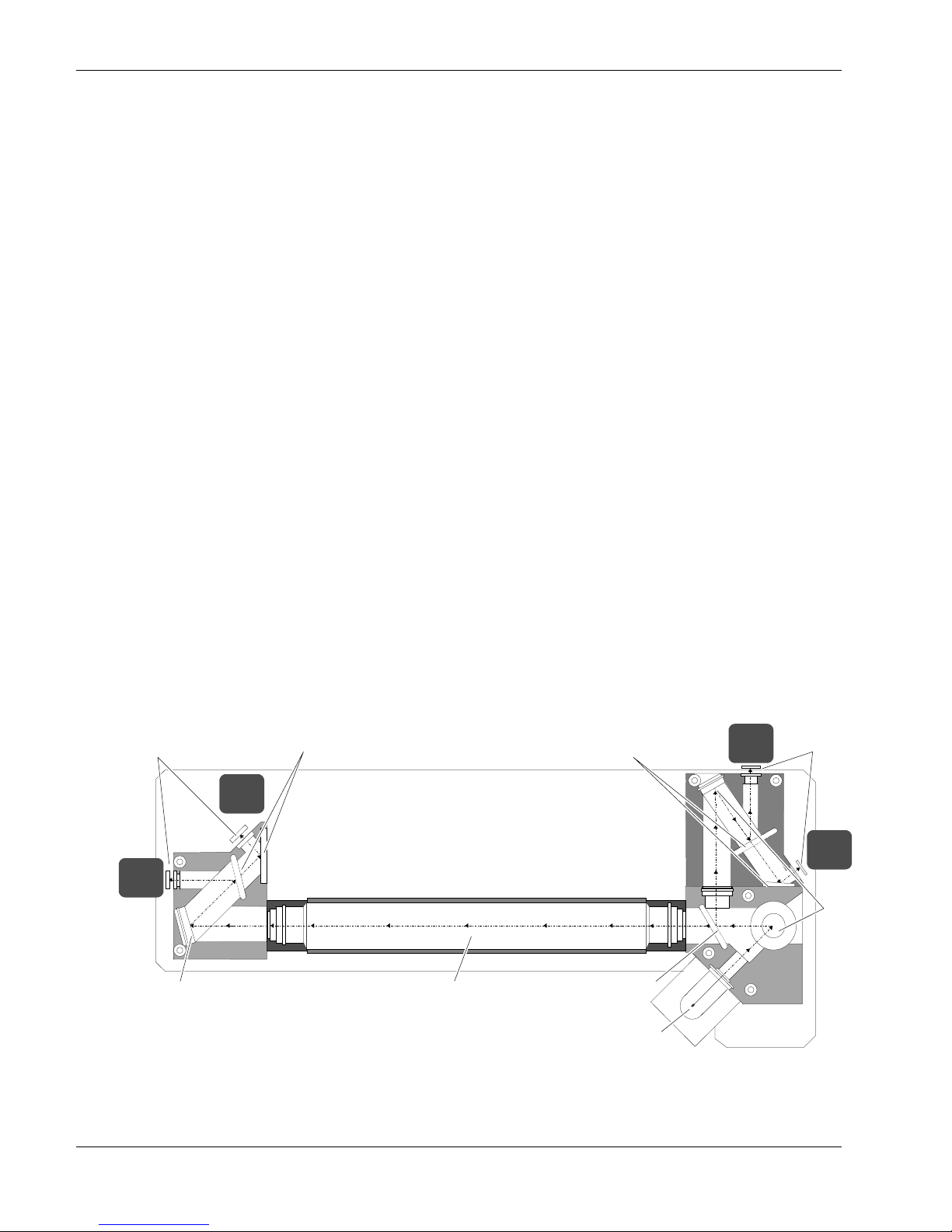
1-1 Model 890 Analyzer................................................................................. 1-1
1-2 Model 890 Optical Bench......................................................................... 1-2
2-1 Power Supply Board................................................................................ 2-2
2-2 Cable Gland Connection.......................................................................... 2-3
2-3 Calibration Gas Control and Alarm Connections...................................... 2-7
2-4 Auto Zero/Span Connections................................................................... 2-8
2-5 Remote Input/Output Connections........................................................... 2-9
3-1 Model 890 Adjustments ........................................................................... 3-1
3-2 Model 890 Keypad................................................................................... 3-2
3-3 Run Mode Display.................................................................................... 3-5
3-4 Logic Flow Chart...................................................................................... 3-7
3-5 Security Mode.......................................................................................... 3-8
3-6 Range Mode ............................................................................................ 3-9
3-7 Diagnostics Mode .................................................................................... 3-12
3-8 Linearization Mode................................................................................... 3-15
3-9 Typical Application Linearization Curve ................................................... 3-16
3-10 Concentration Curve................................................................................ 3-18
3-11 Curve, Normalized................................................................................... 3-18
3-12 Alarm Option............................................................................................ 3-20
3-13 Status Display.......................................................................................... 3-21
3-14 Current Output Mode............................................................................... 3-22
3-15 Auto Zero/Span........................................................................................ 3-25
3-16 Remote Input/Output................................................................................ 3-26
4-1 Model 890 Timing Diagram...................................................................... 4-2
6-1 Optical Bench........................................................................................... 6-2
6-2 Sample Cell Assembly............................................................................. 6-3
6-3. Collector Block (Exploded View).............................................................. 6-5
6-4 Detector Block (Exploded View)............................................................... 6-6
6-5 Lamp Assembly 655000 .......................................................................... 6-7
6-6. Lampl Alignment...................................................................................... 6-8
7-1 Model 890 Component Locations ............................................................ 7-3
7-2 Optical Bench - Sensor Locations............................................................ 7-4
7-3 UV Lamp Life vs. Intensity....................................................................... 7-4
ABLES
T
3-1 Linearization Coefficients, Standard Ranges........................................... 3-16
3-2 Remote Range I/O Bit Designation.......................................................... 3-27
3-3 Remote Range I/O Binary and Decimal Bit Coding.................................. 3-27
5-1 Error Code Summary............................................................................... 5-1
6-1 Jumper Configurations for Options .......................................................... 6-12
IV
January 2000
748460-ARosemount Analytical

RAWINGS (LOCATED IN REAR OF MANUAL
D
623782 Schematic Diagram, Micro Board
624127 Schematic Diagram, Adaptor Board
624204 Schematic Diagram, Dual Alarm/Fail Safe Alarm
624251 Schematic Diagram, Remote Control
624599 Scheamtic Diagram, Auto/Zero Span
652687 Schematic Diagram, Signal Board SO
652715 Diagram, Electrical Interconnect SO
2
2
652807 Schematic Diagram, Power Supply Board
652857 Schematic Diagram, Preamplifier Board SO
2
654853 Installation Drawing, Model 890
656137 Schematic Diagram, Signal Board Cl
656138 Schematic Diagram, Preamplifier Board Cl
656911 Diagram, Electrical Interconnect Cl
2
2
2
C
ONTENTS
)
748460-A
January 2000 Rosemount Analytical
v

C
ONTENTS
OTES
N
VI
January 2000
748460-ARosemount Analytical
REFACE
P
AFETY SUMMARY
S
To avoid explosion, loss of life, personal injury and damage to this equipment and on-site
property, all personnel authorized to install, operate and service the Model 890 Analyzer
should be thoroughly familiar with and strictly follow the instructions in this manual. Save
these instructions.
If this equipment is used in a manner not specified in these instructions, protective
systems may be impaired.
DANGER is used to indicate the presence of a hazard which will cause severe
personal injury, death, or substantial property damage if the warning is ignored.
WARNING is used to indicate the presence of a hazard which can cause severe
personal injury, death, or substantial property damage if the warning is ignored.
CAUTION is used to indicate the presence of a hazard which will or can cause minor
personal injury or property damage if the warning is ignored.
NOTE is used to indicate installation, operation or maintenance information which is
important but not hazard-related.
WARNING: ELECTRICAL SHOCK HAZARD
Do not operate without doors and covers secure. Servicing requires access to
live parts which can cause death or serious injury. Refer servicing to qualified
personnel.
For safety and proper performance this instrument must be connected to a
properly grounded three-wire source of power.
Alarm and zero/span switching relay contacts wired to separate power sources
must be disconnected before servicing.
This instrument is shipped from the factory set up to operate on 115 volt, 50/60
Hz electric power. For operation on 230 volt, 50/60 Hz power, see Section 2.3 for
modifications.
748460-A
January 2000 Rosemount Analytical
P-1
P
REFACE
WARNING: POSSIBLE EXPLOSION HAZARD
This analyzer is of a type capable of analysis of sample gases which may be
flammable. If used for analysis of such gases, the instrument must be protected
by a continuous dilution purge system in accordance with Standard ANSI/NFPA
496-1989, Chapter 8.
If explosive gases are introduced into this analyzer, the sample containment
system must be carefully leak-checked upon installation and before initial
startup, during routine maintenance and any time the integrity of the sample
containment system is broken, to ensure the system is in leak-proof condition.
Leak-check instructions are provided in Section 2.8.
Internal leaks resulting from failure to observe these precautions could result in
an explosion causing death, personal injury or property damage.
WARNING: PARTS INTEGRITY
Tampering or unauthorized substitution of components may adversely affect
safety of this product. Use only factory documented components for repair.
WARNING: INTERNAL ULTRAVIOLET LIGHT HAZARD
Ultraviolet light from the source lamp can cause permanent eye damage. Do not
look at the UV source for prolonged periods. Use of UV filtering glasses is
recommended.
WARNING: HIGH PRESSURE GAS CYLINDERS
This analyzer requires periodic calibration with known zero and standard gases.
See General Precautions for Handling and Storing High Pressure Cylinders, at
the rear of this manual.
P-2
Rosemount Analytical January 2000
748460-A
P
REFACE
WARNING: TOXIC GAS HAZARD
This instrument measures toxic gases. Ensure gas lines are leak-free and
properly vented. Inhalation of toxic gases is highly dangerous and could result
in death.
Also, exhaust gas from this instrument is toxic and equally dangerous. Exhaust
must be connected either to its original source or an appropriate outside vent
using ¼-inch (6mm) tubing minimum.
CAUTION: TOPPLING HAZARD
This instrument’s internal pullout chassis is equipped with a safety stop latch
located on the left side of the chassis.
When extracting the chassis, verify that the safety latch is in its proper (counterclockwise) orientation.
If access to the rear of the chassis is required, the safety stop may be
overridden by lifting the latch; however, further extraction must be done very
carefully to insure the chassis does not fall out of its enclosure.
If the instrument is located on top of a table or bench near the edge, and the
chassis is extracted, it must be supported to prevent toppling.
Failure to observe these precautions could result in personal injury and/or
damage to the product.
748460-A
January 2000 Rosemount Analytical
P-3

P
REFACE
PECIFICATIONS
S
R
ANGE (STD
O
PERATING TEMPERATURE
R
EPEATABILITY
Z
ERO DRIFT
S
PAN DRIFT
N
OISE
R
ESPONSE TIME
(E
LECTRONIC
S
ENSITIVITY
I
NTERFERENT REJECTION
A
NALOG OUTPUT
L
INEARIZATION
P
OWER REQUIREMENTS
) (
1
1
- G
FULLSCALE
)
ENERAL
0 to 50, 0 to 5000 ppm SO2 at atmospheric pressure
)
0 to 100 to 0 to 5000 ppm Cl
SO2 applications: 32°F to 104°F (0°C to 40°C)
Cl2 applications: 59°F to 95°F (15°C to 35°C)
≤1% of fullscale
SO2: ±2% of fullscale per week
Cl
: ±2% of fullscale per 24 hours
2
SO2: ±2% of fullscale per week
Cl2: ±2% of fullscale per 24 hours
≤1% of fullscale
Variable, 90% of fullscale in 0.5 sec. to 20 sec, field
selectable (application dependent)
SO2: ≤0.1 ppm
Cl2: ≤0.2 ppm
Discrimination ratio for NO2 is 1000:1 for SO2 applications
Standard: 0 to 5 VDC and 0 to 20 mA/4 to 20 mA DC,
isolated (maximum load 700 ohms)
Keypad entered coefficients for linearizing 1, 2 or (all) 3
ranges
115/230 VAC ±10%, 50/60 Hz, 350 Watts
at atmospheric pressure
2
PECIFICATIONS
S
S
AMPLE CELL
M
ATERIALS IN CONTACT WITH SAMPLE
W
INDOWS
C
ELLS
T
UBING
F
ITTINGS
O-R
INGS
S
AMPLE PRESSURE
1. Performance specifications based on ambient temperature shifts of less than 20° Fahrenheit (11° Celsius) per hour.
- S
AMPLE
12.0 inches (305 mm) long, 110 cc volume
Suprasil II
Pyrex
FEP Teflon
316 Stainless Steel
Viton-A
Maximum 10 psig (69 kPa)
P-4
Rosemount Analytical January 2000
748460-A

P
REFACE
PECIFICATIONS
S
E
NCLOSURE
D
IMENSIONS
W
EIGHT
PECIFICATIONS
S
A
LARM
C
ALIBRATION GAS CONTROL
A
UTO ZERO/SPAN
R
EMOTE INPUT/OUTPUT
2
A
LARM RELAY
C
ONTACTS
R
ELAY OUTPUTS
R
ELAY OUTPUTS
R
ANGE CHANGE
HYSICAL
- P
PTIONS
- O
General purpose for installation in weather-protected area.
Optional purge kit per Type Z, ANSI/NFPA 496-1993
1
8.7 x 19 x 24 inches (221 x 483 x 610 mm) H x W x D
65 lbs. (30 kg)
Two single point, field programmable high or low,
deadband up to 20% of fullscale
Two Form C contact rated 3A, 125/250 VAC or 5A, 30 VDC
(resistive)
Two front panel actuated contact closures
Two Form C contact rated 3A, 125/250 VAC or 5A, 30 VDC
(resistive)
Four form C contact closures, rated 3A, 125/250 VAC or
5A, 30 VDC (resistive), field programmable frequency and
duration of closure
Two form A contact closures for indication of insufficient
zero and span adjustment, rated (resistive load):
Max. switching power: 10 Watts
Max. switching voltage: 30 VDC
Max. switching current: 0.5 A
Three remotely changeable ranges with positive
identification.
Binary or decimal, field selectable.
A
UTO ZERO/SPAN
Auto Cal request and status.
Eight form A contact rated (resistive load):
R
ELAY OUTPUTS
Max. switching power: 10 Watts
Max. switching voltage: 30 VDC
Max. switching current: 0.5 A
I
NPUTS
I
NPUT RANGE
1 When installed with user-supplied components, meets requirements for Class I, Division 2 locations per National
Electrical Code (ANSI/NFPA 70) for analyzers sampling nonflammable gases. Analyzers sampling flammable gases
must be protected by a continuous dilution purge system in accordance with Standard ANSI/NFPA 496-1993, Chapter 6.
Consult factory for recommendations.
2 Fail-safe jumper configuration.
Eight optical couplers
+5 VDC to +24 VDC
748460-A
January 2000 Rosemount Analytical
P-5

P
REFACE
USTOMER SERVICE
C
For order administration, replacement parts, application assistance, on-site or factory
repair, service or maintenance contract information, contact:
ETURNING PARTS TO THE FACTORY
R
Before returning parts, contact the Customer Service Center and request a Returned
Materials Authorization (RMA) number. Please have the following information when
you call: Model Number, Serial Number, and Purchase Order Number or Sales Order
Number.
Prior authorization by the factory must be obtained before returned materials will be
accepted. Unauthorized returns will be returned to the sender, freight collect.
When returning any product or component that has been exposed to a toxic, corrosive
or other hazardous material or used in such a hazardous environment, the user must
attach an appropriate Material Safety Data Sheet (MSDS) or a written certification that
the material has been decontaminated, disinfected and/or detoxified.
ECHNICAL ASSISTANCE AND FIELD SERVICE
, T
Rosemount Analytical Inc.
Process Analytical Division
Customer Service Center
1-800-433-6076
Return to:
Rosemount Analytical Inc.
4125 East La Palma Avenue
Anaheim, California 92807-1802
USA
RAINING
T
A comprehensive Factory Training Program of operator and service classes is
available. For a copy of the Current Operator and Service Training Schedule contact
the Technical Services Department at:
Rosemount Analytical Inc.
Phone: 1-714-986-7600
FAX: 1-714-577-8006
OCUMENTATION
D
The following Model 890 Analyzer instruction materials are available. Contact
Customer Service or the local representative to order.
748460 Instruction Manual (this document)
P-6
Rosemount Analytical January 2000
748460-A
OMPLIANCES
C
P
REFACE
M
ODEL
The Model 890 SO2 Analyzer is intended for sampling only non-hazardous gases in
non-hazardous locations. When equipped with the optional Type Z Purge Kit (PN
624446), this analyzer is approved for use in Class I, Division 2, Groups B, C, and D
hazardous locations and use indoor non-hazardous locations when sampling
flammable gases.
Rosemount Analytical has satisfied all obligations from the European Legislation to
harmonize the product requirements in Europe.
This product complies with the standard level of NAMUR EMC. Recommendation (May
1993).
890 SO
ANALYZER
2
97-C209
NAMUR
This product satisfies all obligations of all relevant standards of the EMC framework in
Australia and New Zealand.
N96
M
ODEL
The Model 890 Cl2 Analyzer is intended for sampling only non-hazardous gases in
non-hazardous locations. When equipped with the optional Type Z Purge Kit (PN
624446), this analyzer is approved for use in Class I, Division 2, Groups B, C, and D
hazardous locations and use indoor non-hazardous locations when sampling
flammable gases.
890 Cl
FM
APPROVED
ANALYZER
2
748460-A
January 2000 Rosemount Analytical
P-7

P
REFACE
OTES
N
P-8
Rosemount Analytical January 2000
748460-A
NTRODUCTION
I
1.1 GENERAL DESCRIPTION
The Model 890 Ultraviolet Analyzer is designed to determine continuously the
concentration of the component of interest in a flowing gaseous mixture. The analyzer
is capable of measurement in the 50 to 5,000 ppm range for SO2 and 100 to 5,000
ppm for Cl2.
F
IGURE
748460-A
1-1. M
O
PTICAL BENCH
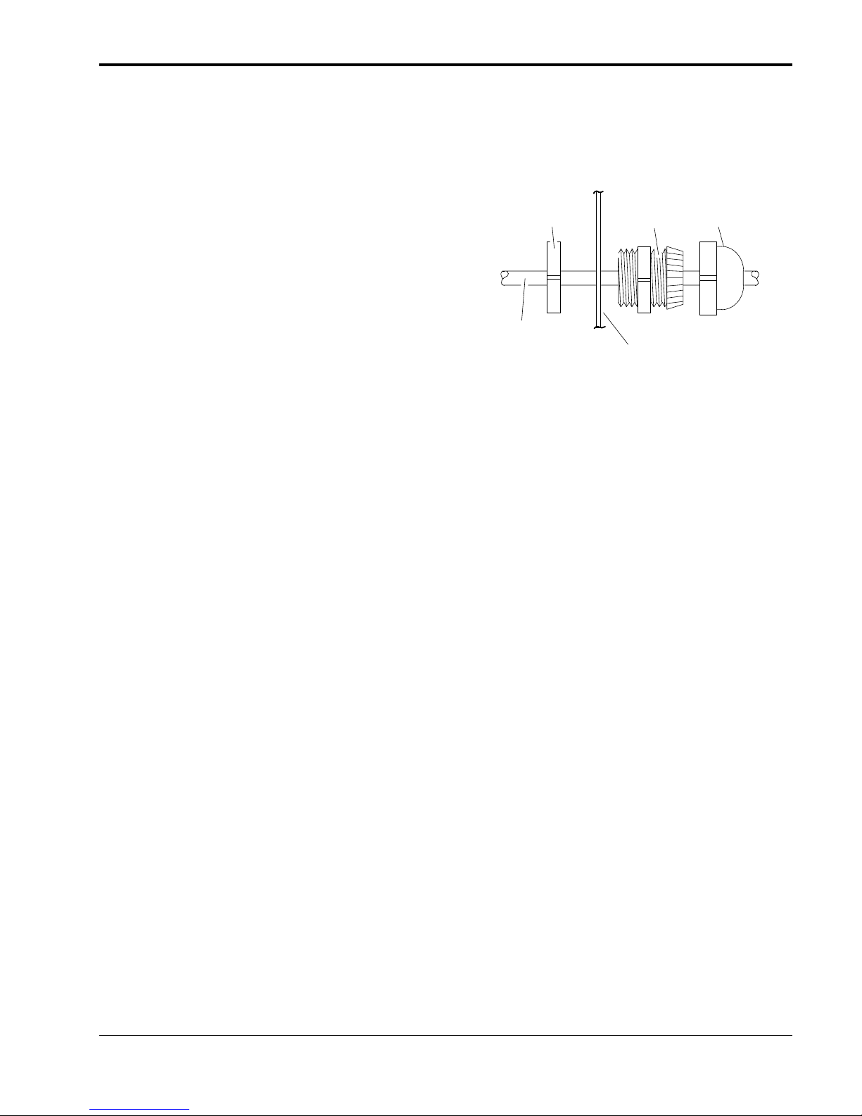
The ultraviolet source emits a pulsed (30 Hz) beam of energy. This energy is split by a
beam splitter, each beam being directed to pairs of detectors before and after the
sample cell.
One of the unique features of the Model 890 is the use of spectrally selective,
“Transflectance”© mirrors. These mirrors isolate the sample and reference spectral
passbands for the detectors. They reflect energy below a wavelength region and
ODEL
890 A
NALYZER
January 2000
Rosemount Analytical
1-1
I
NTRODUCTION
transmit the remaining, higher wavelengths, all with much lower energy loss than the
more commonly used bandpass interference filters.
Four detectors are used in this system, two before the sample cell (sample before [Sb]
and reference before [Rb]) and two after (sample after [Sa] and reference after [Ra]).
Sb and Sa receive energy in the specific wavelength regions depending on the
application (265 to 310 nm for SO2, 310 to 355 nm for Cl2), Rb and Ra in the 310 to 355
nm region for SO2 and 355 to 400 nm for Cl2.
These four detectors measure the component of interest (COI) concentration and
correct for NO2 interference and UV lamp fluctuations. The difference between
detector determinations is the COI concentration, following this formula:
COI = [f(Rb)-Sb]-[f(Ra)-Sa]
where:
Ra, Rb, Sa, Sb = signals from those detectors so identified
f = attenuation factor for the reference signal, adjusted to compensate for NO2
interference.
The sample gas is introduced to the sample cell, and the COI absorbs ultraviolet
energy in proportion to the concentration in the gas. The difference between the
signals of the detectors located at both ends of the sample cell determines the
concentration of COI in the sample.
DETECTORS
a
MIRROR
TRANSFLECTANCE©
MIRRORS
a
SAMPLE CELL
TRANSFLECTANCE©
MIRRORS
BEAM SPLITTER
DETECTORS
b
b
MIRRORS
F
IGURE
1-2
1-2. M
Rosemount Analytical
ODEL
890 O
January 2000
UV LAMP
PTICAL BENCH
748460-A

I
NTRODUCTION
Additionally, the adjacent (non-COI-absorbing) reference wavelengths are used as a
baseline for measurement and correction of sample interferent components,
particularly NO2.
Readout is on a 16-character, LED-backlighted liquid crystal display. COI
concentration data is presented in parts per million, percent of composition, or percent
of fullscale. Additionally, 0 to +5 VDC output for a potentiometric (voltage) recorder
and 0 to 20 mA or 4 to 20 mA isolated current output (maximum load 700 ohms) are
provided as standard.
A case heater with fan assembly maintains proper operating temperature.
L
INEARIZATION
A linearizer, based on a fourth-order polynomial, is incorporated in the electronic
circuitry. By turning the linearizer ON and entering the correct coefficients, an output
linear with concentration is obtained.
1.2 AVAILABLE OPTIONS
Operation of the Model 890 can be enhanced with the choice of several options:
D
UAL ALARMS (STANDARD AND FAIL-SAFE
User-set dual alarms are available with configurable HI/LO designations and
deadband.
A
UTO ZERO/SPAN
An Automatic Zero/Span Option is available for unattended calibration of all three
ranges.
C
ALIBRATION GAS CONTROL
A Calibration Gas Control Option allows two solenoids to be remotely actuated from
the front panel, enabling one-man calibration without leaving the analyzer.
R
EMOTE RANGE
I/O
An optional remote range input/output is available.
)
A
IR PURGE KIT
Air purge kit, when installed with user-supplied components, meets Type Z
requirements of standard ANSI/NFPA 496-1993 for installation in Class I, Division 2
locations as defined in the National Electrical Code (ANSI/NFPA 70) when sampling
748460-A
January 2000 Rosemount Analytical
1-3

I
NTRODUCTION
nonflammable gases. If the analyzer is used to sample a flammable gas, it must be
protected by a continuous dilution purge system per standard ANSI/NFPA 496-1993,
Chapter 6, or IEC publication 79-2-1983, Section Three. (Consult factory for further
information.)
1-4
Rosemount Analytical
January 2000
748460-A
NPACKING AND INSTALLATION
U
2.1 CHECK FOR SHIPPING DAMAGE
Examine the shipping carton and contents carefully for any signs of damage. Save the
carton and packing material until the analyzer is operational. If carton or contents
damage (either external or concealed) is discovered, notify the carrier immediately.
2.2 LOCATION
Locate the analyzer in a weather-protected, non-hazardous location free from
vibration. For best results mount the analyzer near the sample stream to minimize
sample-transport time. Refer to Installation Drawing 654853.
If equipped with PN 624446 optional air purge kit and installed with user-provided
components per Instructions 015-748157, the analyzer may be located in a Class I,
Division 2 area as defined by the National Electrical Code (ANSI/NFPA 70). This kit is
designed to provide Type Z protection in accordance with Standard ANSI/NFPA
496-1993, Chapter 2, when sampling nonflammable gases. For flammable samples,
the instrument must be equipped with a continuous dilution purge system in
accordance with ANSI/NFPA 496-1993, Chapter 6. Consult factory for
recommendations concerning minimum purge flow requirements for your particular
application.
2.3 VOLTAGE REQUIREMENTS
WARNING: ELECTRICAL SHOCK HAZARD
For safety and proper performance this instrument must be connected to a
properly grounded three-wire source of electrical power.
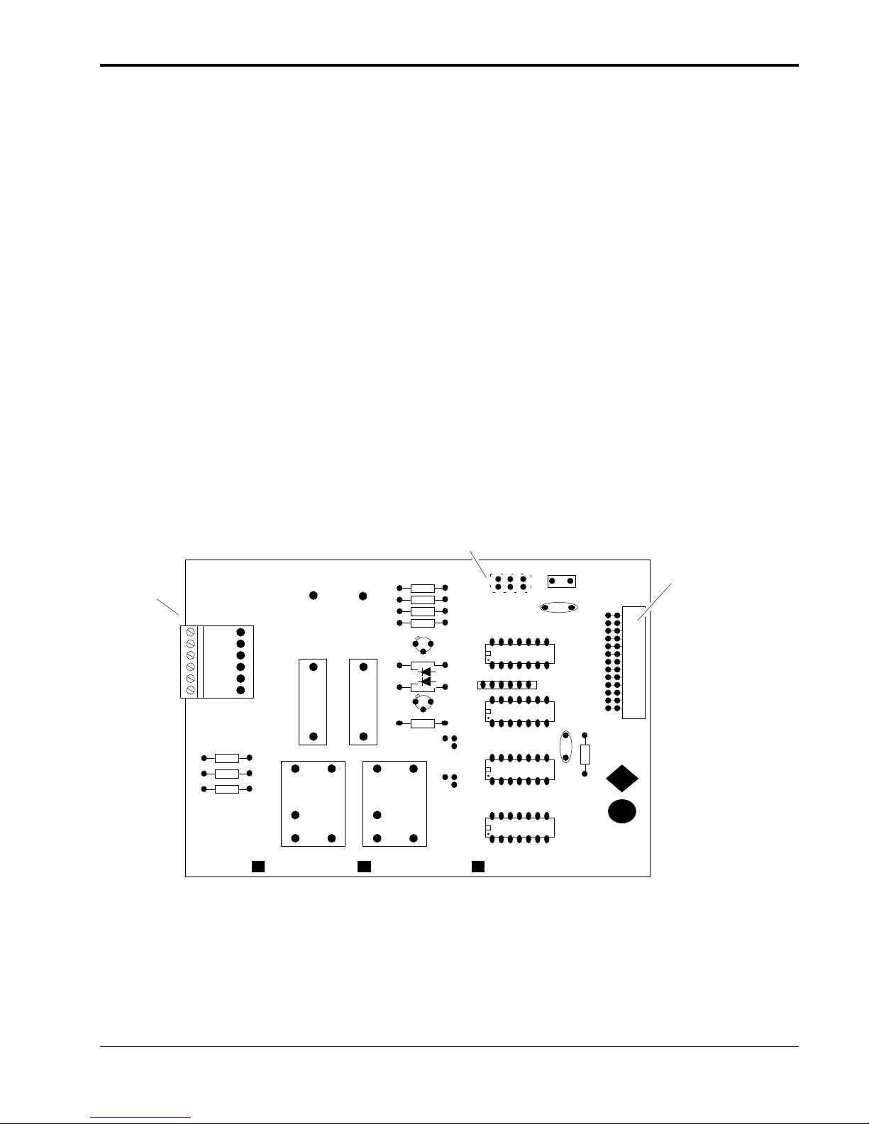
This instrument was shipped from the factory set up to operate on 115 VAC, 50/60 Hz
electric power. For operation on 230 VAC, 50/60 Hz the installer must position voltage
select switches S1 and S2 located on power supply board to the 230 VAC position
(see Figure 2-1).
Power consumption is 350 watts.
748460-A
January 2000 Rosemount Analytical
2-1
U
NPACKING AND INSTALLATION
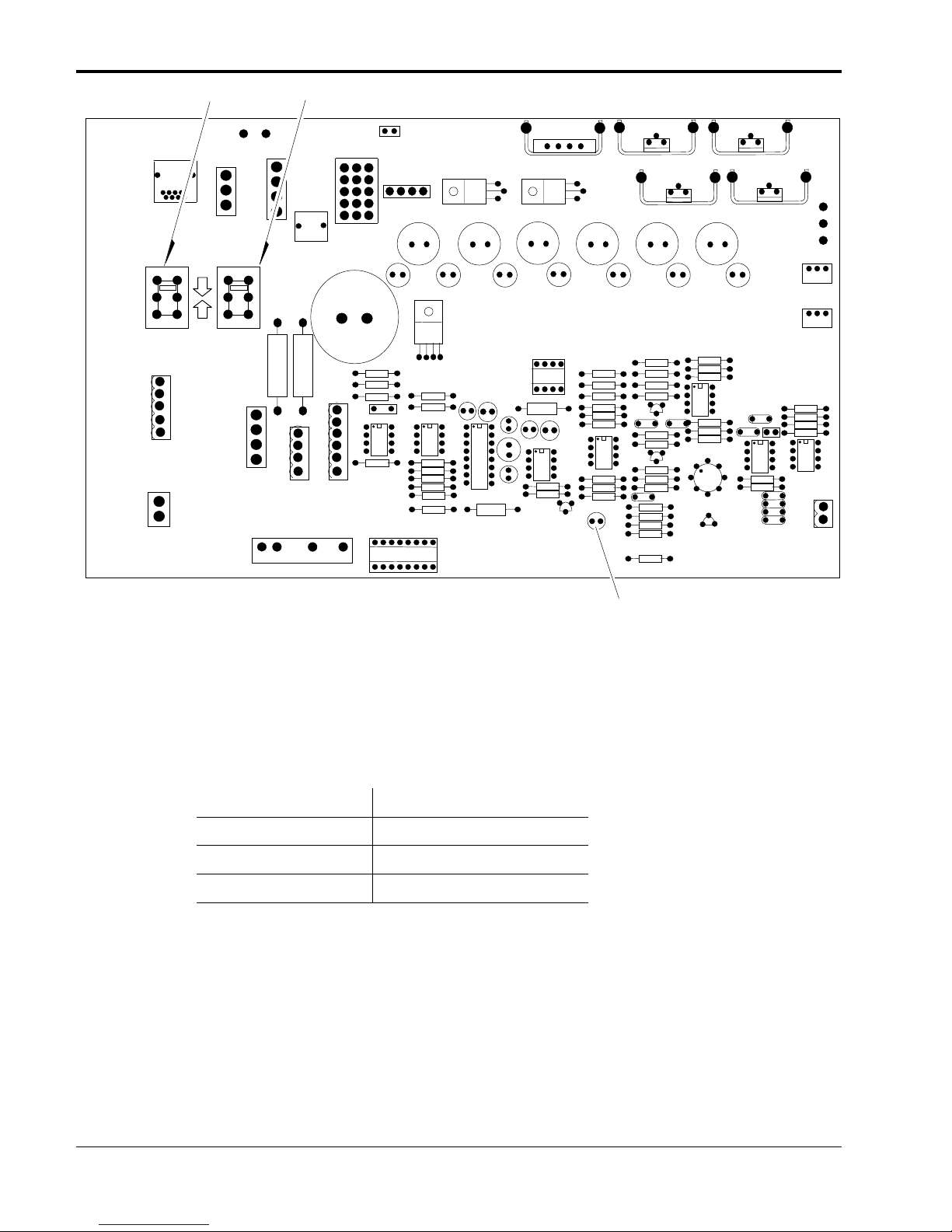
S1 S2
S1
115 115
J11
1
HEATER
J16
1
BACKLIGHT
230V
115V
TP4 TP5
S2
J2
1
FAN
1
J8
LAMP
K1
F1
HEATSINK
E1
E1
TP1
TP2
+
+
J9
1
+
+
+ +
1
J7
+
++
J13
+
+ +
+
+
652810
POWER SUPPLY
+
+
1
+
+
+
+
+
TP3
ZERO
SPAN
TEMP
SENSOR
J5
D6
F
IGURE
2-1. P
OWER SUPPLY BOARD
2.4 ELECTRICAL CONNECTIONS
The power, recorder and current output cable glands are shipped already installed to
allow attachment of cables to connectors or terminal strips. Cable glands for specific
cables are as follows:
CABLE GLAND PART NO.
P
OWER
R
ECORDER
C
URRENT OUTPUT
Remove the rear cover to access the terminals. Route each cable through the cable
gland and connect to appropriate connector or terminal strip as shown in Drawings
654853 and 652715. Then, tighten the gland.
2.4.1 L
INE POWER CONNECTIONS
If this instrument is located on a bench or table top or is installed in a protected rack,
panel or cabinet, power may be connected to it via a 3-wire flexible power cord,
minimum 18 AWG (max. O.D. 0.480", min. O.D. 0.270") through hole “F” (refer to
Drawing 654853) utilizing the connector gland (PN 899330) provided.
899330
899329
899329
2-2
Rosemount Analytical
January 2000
748460-A
U
NPACKING AND INSTALLATION
Accessory kits are available which include one of the following: 1) a 10-foot North
American power cord set and four enclosure support feet (PN 654008) for bench top
use, 2) the power cord only (PN 634061), or 3) the four feet only (PN 634958). If the
instrument is permanently mounted in an open panel or rack, use electrical metal
tubing or conduit.
Refer to Figure 2-2 and Drawings
654853, 652715 and 656139. Route
INTERIOR EXTERIO R
Nut Gland Nut
the power cable through the cable
gland and connect the leads to TB1.
After connecting the leads, tighten
the cable gland adequately to
prevent rotation or slippage of the
power cable. Since the rear
terminals do not slide out
Cable
Case Wall
with<D%0> the chassis, no excess
power cable slack is necessary.
2.4.2 R
ECORDER CONNECTIONS
F
IGURE
2-2. C
C
ABLE GLAND
ONNECTION
Recorder connections are made to the rear panel. Refer to Drawings 654853, 652715
and 656139. Route the recorder cable through the cable gland and connect to TB2.
Recorder and interconnection cables should meet the following requirements:
V
OLTAGE OUTPUT
: 0
+5 VDC
TO
• Maximum distance from recorder to analyzer: 1000 ft. (305 m)
• Recorder input impedance: >5000 ohms
• Customer-supplied cable: 2-conductor, 20 AWG (min.), shielded
I
SOLATED CURRENT OUTPUT
PROGRAMMABLE
)
: 0
TO
20 MA
OR 4 TO
20 MA (
• Maximum load impedance: 700 ohms
KEYBOARD
748460-A
January 2000 Rosemount Analytical
2-3

U
NPACKING AND INSTALLATION
2.5 SAMPLE INLET/OUTLET CONNECTIONS
The standard Model 890 is intended for atmospheric pressure operation only, and
must be vented to either the atmosphere or a collection destination at atmospheric
pressure. Sample inlet and outlet connections are located on the rear panel. All
connections are 1/4-inch ferrule-type compression fittings. See Drawing 654853.
WARNING: TOXIC GAS HAZARD
This instrument measures toxic gases. Ensure gas lines are leak-free and
properly vented. Inhalation of toxic gases is highly dangerous and could result
in death.
Also, exhaust gas from this instrument is toxic and equally dangerous. Exhaust
must be connected either to its original source or an appropriate outside vent
using ¼-inch (6mm) tubing minimum.
WARNING: POSSIBLE EXPLOSION HAZARD
This analyzer is of a type capable of analysis of sample gases which may be
flammable. If used for analysis of such gases, the instrument must be protected
by a continuous dilution purge system in accordance with Standard ANSI/NFPA
496-1989, Chapter 8.
If explosive gases are introduced into this analyzer, the sample containment
system must be carefully leak-checked upon installation and before initial
startup, during routine maintenance and any time the integrity of the sample
containment system is broken, to ensure the system is in leak-proof condition.
Leak-check instructions are provided in Section 2.8.
Internal leaks resulting from failure to observe these precautions could result in
an explosion causing death, personal injury or property damage.
2-4
Rosemount Analytical
January 2000
748460-A
U
NPACKING AND INSTALLATION
2.6 CALIBRATION GAS REQUIREMENTS
Analyzer calibration consists of setting a zero point and one or more upscale points.
All applications require a zero standard gas to set the zero point on the display or
recorder chart. If the factory Calibration and Data Sheet (included with the drawings at
the end of the manual) specifies a background gas, use this as the zero gas. If a
background gas is not specified, use dry nitrogen for the zero gas. Ideally, span gas
should be between 75 % and 100 % of the fullscale span.
2.7 SAMPLE HANDLING SYSTEM
Many different sample handling systems are available, either assembled completely or
as loose components. The type used depends on the requirements of the particular
application and the preferences of the individual user. Typically, the sample handling
system incorporates such components as pumps and valves to permit selection of
sample, zero standard and upscale standard gas; needle valve in sample-inlet line for
flow adjustment; flowmeter for flow measurement and/or indication of flow stoppage;
and filter(s) to remove particulate matter.
2.8 LEAK TEST PROCEDURE
WARNING: POSSIBLE EXPLOSION HAZARD
This analyzer is capable of analyzing sample gases which may be flammable. If
used for analysis of such gases the instrument must be protected by a
continuous dilution purge system in accordance with Standard ANSI/NFPA 4961989 (Chapter 8).
If explosive gases are introduced into the analyzer, the sample containment
system must be leak checked upon installation and before initial startup, during
routine maintenance and any time the integrity of the sample containment
system is broken, to ensure that the system is in leak proof condition.
Internal leaks resulting from failure to observe these precautions could result in
an explosion causing death, personal injury or property damage.
The following test is designed for sample pressure up to 10 psig (69 kPa).
1. Supply air or inert gas such as nitrogen at 10 psig (69 kPa) to analyzer via a flow
indicator with a range of 0 to 250 cc/min and set flow rate at 125 cc/min to the
sample inlet.
2. Seal off sample outlet with a cap.
3. Use a suitable test liquid such as SNOOP* (PN 837801) to detect leaks. Cover all
fittings, seals or possible leak sources.
748460-A
January 2000
Rosemount Analytical
2-5

U
NPACKING AND INSTALLATION
4. Check for bubbling or foaming which indicates leakage and repair as required. Any
leakage must be corrected before introduction of sample and/or application of
electrical power.
Note
Do not allow test liquid to contaminate cell or detectors and UV source
windows. Should this occur, follow instructions in subsection 6.1 to clean the
cell.
2.9 SAMPLE FLOW RATE
Recommended sample flow rate is 1 to 2 SCFH (500 to 1000 cc/min). A subnormal
flow rate will not affect readings but may result in an undesirable time lag. However,
an excessive flow rate can result in cell pressurization.
Assume that two cell volumes are required to flush any cell. Approximate flushing time
for the Model 890's 12-inch cell at atmospheric sampling pressure (i.e., the outlet of
the cell venting to atmosphere) is approximately 12 seconds.
Flushing time is inversely proportional to flow rate.
The primary effect of flow rate, other than flushing time, is cell pressure. Due to
restrictions in exit flow configuration, an increasing flow rate increases sample
pressure in the cell.
In all cases, the effect of pressure on readout is eliminated if the same flow rate is
used for the measured sample as well as for the zero gas and span gas.
Note that at higher flow rates the nonlinearity of the calibration curve increases,
because of increase in sample cell pressure. Therefore, if higher flow rates are
required, the calibration curve should be redrawn at the higher rate.
At flows up to 2 CFH (1 L/min), gaseous sample temperatures are equilibrated to
instrument temperature regardless of stream temperature. At extremely high flow
rates, this may not be true, but no such effect has been noted up to 18 CFH (9 L/min).
2.10 OPTION BOARDS
The following option boards may be ordered factory installed or may be ordered as kits
from the factory at a later date: Alarm, Calibration Gas Control, Auto Zero/Span and
Remote Range I/O. The boards are equipped with mating plugs for field wiring
attached to the connector at the edge of each board. Attach the cable (customer
supplied) to the plug and socket connector according to the schematic for each option
board.
If an option board has been ordered installed at the factory, this board will be inserted
into one of five slots inside the rear of the analyzer. Each option will require a cable
(user-provided) which connects to a female plug. The female plug, in original
packaging, is attached to the appropriate terminal block on the option board. If the
instrument came equipped with one option, the interconnect cable will be in place for
all options.
2-6
Rosemount Analytical
January 2000
748460-A
U
NPACKING AND INSTALLATION
The Alarm, Auto Zero/Span, Calibration Gas Control and Remote Range Change
Boards have jumper-selectable addresses.
2.10.1 A
LARM CONNECTIONS
Refer to Figure 2-3 and Drawings 652715 and 656139. Connect cable (customer
supplied) to the 6-pin connector J2. The Dual Alarm Option consists of two form C
contacts rated 3A-125/250 VAC or 5A-30 VDC (resistive).
Run the cable through the cable gland and tighten once the connector has been
secured (Figure 2-2).
2.10.2 C
ALIBRATION GAS CONTROL CONNECTIONS
Refer to Figure 2-3 and Drawings 652715 and 656139. Connect cable (customer
supplied) to the 6-pin connector J2. The Cal. Gas Control Option consists of two form
C contacts rated 3A-125/250 VAC or 5A-30 VDC (resistive).
Run the cable through the cable gland and tighten the latter once the connector has
been secured (Figure 2-2).
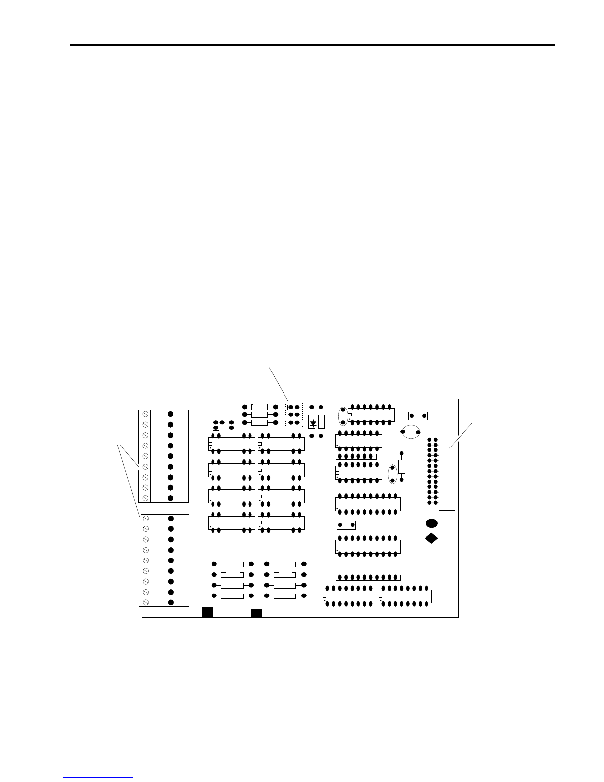
Jumper Selectable
Outlet
Cable
J2
R5
R4
R3
A
C
B B
Address
E4 E2 E1
R1
R2
R8
R6
C
E
FT2FT1
Q1
B
CR1
1
A
E
Q2
C
R7
B
E8
E6
1
CR2
C
1
E10
E9
E7
1
E5
C1
PR1
C1
U1
U2
C3
U3
J1
1
+
R9
Interconnect
Cable
K1
624419 CTRL
Note: The Dual Alarm, Fail Safe Alarm and Calibration Gas Control use the same board. However, the jumpers
locations are different.
Cal Gas Control: E1, E4, E5 - E7 and E9 - E10
Dual Alarm: E1, E2, E5 - E7 and E9 - E10
Fail Safe Alarm: E1, E2, E6 - E7 and E8 - E10
F
IGURE
748460-A
2-3. C
ALIBRATION GAS CONTROL AND ALARM CONNECTIONS
CAL
K2
624207 ALARM
DUAL
1
FA IL
654398 SAFE ALARM
U4
January 2000
Rosemount Analytical
2-7
U
NPACKING AND INSTALLATION
2.10.3 A
UTO ZERO/SPAN CONNECTIONS
Refer to Figure 2-4 and Drawings 652715 and 656139. Connect cable (customer
supplied) to the 9-pin connectors J2 and J3. The Auto Zero/Span Option consists of
four form C contacts rated 3A-125/250 VAC or 5A-30 VDC (resistive) and two form A
contacts rated at 10 watts maximum switching power, 200 VDC maximum switching
voltage and 0.5 A maximum switching current.
Run the cable through the cable gland and tighten once the connector has been
secured (Figure 2-2).
If installed, this board can also be activated from the keyboard (Zero/Span) for the
selected range.
Jumper Selectable
Address
Outlet
Cable
J2
FT1 K1
FT2 K2
C
Q1
CR1
C
Q2
B
E
R4
K5
B
E
K4FT4
B
C
E
Q5
U1
R1R1
R2
R3
C3
C
Q4
CR4
B
E
C1
R7
E4 E2 E1
C2
+
J1
1
Interconnect
Cable
F
IGURE
2-4. A
R5
CR2
FT3
J3
C
Q1
CR3K3R6
B
E
UTO ZERO/SPAN CONNECTIONS
K6
CR5
C
Q1
R8
B
RP1
R10
E
U3
1
1
1
U2
1
1 U4
2-8
Rosemount Analytical
January 2000
748460-A
U
6
NPACKING AND INSTALLATION
2.10.4 R
EMOTE INPUT
/ O
UTPUT CONNECTIONS
Refer to Figure 2-5 and Drawings 652715 and 656139. Connect cable (customer
supplied) to the 9-pin connectors J2 and J3.
The signal output is at J2 which consists of eight form A contacts rated (resistive load)
10 watts, maximum switching power, 200 VDC maximum switching voltage and 0.5 A
maximum switching current.
The signal input is at J3 which consists of eight optocouplers, operated from a
user-supplied 24 VDC power source.
Run the cable through the cable gland and tighten once the connector has been
secured (Figure 2-2).
Jumper Selectable
Address
F
IGURE
Outlet
Cable
2-5. R
CR1 R13
K5
K6
K7
K8
R7
R8
R9
R10
E4
E2
C5
E1
U1
RP2
C2
11
J2
J3
R11
E5 E6 E7
24254 654416 ISOLATE D R EMOTE CONTROL BD
R2
R1
E9E8
K1
K2
K3
K4
R3
R4
R5
R6
EMOTE INPUT/OUTPUT OPTIONS
C1
U7
J1
+
1
1
1
1
1
1
C3
R12
C4
U2
U3
U4
RP1
U5U6
Interconnect
Cable
748460-A
January 2000
Rosemount Analytical
2-9
 Loading...