

Page 1
Reference Manual
00809-0100-8782, Rev AA
Rosemount® 8782 Slurry Magnetic Flow
Meter Transmitter with HART Protocol
November 2019
Page 2

2
Page 3

Reference Manual Contents
00809-0100-8782 November 2019
Contents
Chapter 1 Hazard messages........................................................................................................... 7
1.1 Safety messages...............................................................................................................................8
Chapter 2 Introduction.................................................................................................................11
2.1 System description.........................................................................................................................11
2.2 Product recycling/disposal............................................................................................................. 12
Chapter 3 Sensor Installation....................................................................................................... 13
3.1 Handling and Lifting Safety.............................................................................................................13
3.2 Location and Position..................................................................................................................... 14
3.3 Sensor Installation.......................................................................................................................... 17
3.4 Process reference connection.........................................................................................................20
Chapter 4 Remote Transmitter Installation...................................................................................25
4.1 Pre-installation............................................................................................................................... 25
4.2 Transmitter symbols.......................................................................................................................28
4.3 Mounting....................................................................................................................................... 28
4.4 Wiring............................................................................................................................................ 29
Chapter 5 Basic Configuration...................................................................................................... 41
5.1 Basic Setup..................................................................................................................................... 41
5.2 Local operator interface (LOI)......................................................................................................... 42
5.3 Other configuration tools............................................................................................................... 42
5.4 Measurement units........................................................................................................................ 42
Chapter 6 Advanced installation details........................................................................................45
6.1 Hardware switches......................................................................................................................... 45
6.2 Pulse output and discrete input/outputs........................................................................................ 47
6.3 Coil housing configuration............................................................................................................. 56
Chapter 7 Operation.................................................................................................................... 61
7.1 Introduction................................................................................................................................... 61
7.2 Local operator interface (LOI)......................................................................................................... 61
Chapter 8 Advanced Configuration Functionality......................................................................... 69
8.1 Introduction................................................................................................................................... 69
8.2 Configure outputs.......................................................................................................................... 69
8.3 Configure HART..............................................................................................................................81
8.4 Configure LOI/Display.....................................................................................................................84
8.5 Additional parameters....................................................................................................................85
8.6 Configure special units................................................................................................................... 87
Chapter 9 Advanced Diagnostics Configuration............................................................................89
Reference Manual iii
Page 4

Contents Reference Manual
November 2019 00809-0100-8782
9.1 Introduction................................................................................................................................... 89
9.2 Meter factors..................................................................................................................................90
9.3 Licensing and enabling................................................................................................................... 90
9.4 Tunable empty pipe detection........................................................................................................91
9.5 Electronics temperature................................................................................................................. 92
9.6 Ground/wiring fault detection........................................................................................................ 93
9.7 High process noise detection..........................................................................................................94
9.8 Coated electrode detection............................................................................................................95
9.9 4-20 mA loop verification............................................................................................................... 96
9.10 Smart Meter Verification.............................................................................................................. 98
9.11 Run commanded Smart Meter Verification.................................................................................100
9.12 Continuous Smart Meter Verification......................................................................................... 101
9.13 Smart Meter Verification test results.......................................................................................... 102
9.14 Smart Meter Verification measurements.................................................................................... 103
9.15 Optimizing the Smart Meter Verification.................................................................................... 105
Chapter 10 Digital Signal Processing............................................................................................ 107
10.1 Introduction............................................................................................................................... 107
10.2 Process noise profiles................................................................................................................. 107
10.3 High process noise diagnostic.................................................................................................... 107
10.4 Optimizing flow reading in noisy applications.............................................................................108
10.5 Explanation of signal processing algorithm.................................................................................111
Chapter 11 Maintenance..............................................................................................................115
11.1 Introduction............................................................................................................................... 115
11.2 Safety information......................................................................................................................115
11.3 Installing a LOI/Display............................................................................................................... 116
11.4 Replacing a terminal block socket module..................................................................................117
11.5 Replacing a terminal block with amp clips.................................................................................. 118
11.6 Trims..........................................................................................................................................119
Chapter 12 Troubleshooting........................................................................................................ 123
12.1 Introduction............................................................................................................................... 123
12.2 Safety information......................................................................................................................123
12.3 Installation check and guide....................................................................................................... 124
12.4 Diagnostic messages..................................................................................................................125
12.5 Basic troubleshooting.................................................................................................................135
12.6 Sensor troubleshooting.............................................................................................................. 140
12.7 Installed sensor tests.................................................................................................................. 142
12.8 Uninstalled sensor tests..............................................................................................................144
12.9 Technical support and service.....................................................................................................146
Appendix A Product Specifications................................................................................................149
A.1 Rosemount 8782 Slurry Magnetic Flow Meter Platform Specifications......................................... 149
iv Rosemount® 8782 Slurry Magnetic Flow Meter Transmitter with HART Protocol
Page 5

Reference Manual Contents
00809-0100-8782 November 2019
A.2 Transmitter specifications............................................................................................................ 153
A.3 MS Sensor Specifications..............................................................................................................160
A.4 8785 Reference Calibration Standard........................................................................................... 165
Appendix B Product Certifications................................................................................................ 167
Appendix C Wiring Diagrams........................................................................................................ 169
C.1 Wiring sensor to transmitter........................................................................................................ 169
C.2 775 Smart Wireless THUM™ Adapter wiring diagrams...................................................................170
C.3 Field Communicator wiring diagrams...........................................................................................172
Reference Manual v
Page 6

Contents Reference Manual
November 2019 00809-0100-8782
vi Rosemount® 8782 Slurry Magnetic Flow Meter Transmitter with HART Protocol
Page 7

Reference Manual Hazard messages
00809-0100-8782 November 2019
1 Hazard messages
This document uses the following criteria for hazard messages based on ANSI standards
Z535.6-2011 (R2017).
DANGER
Serious injury or death will occur if a hazardous situation is not avoided.
WARNING
Serious injury or death could occur if a hazardous situation is not avoided.
CAUTION
Minor or moderate injury will or could occur if a hazardous situation is not avoided.
NOTICE
Data loss, property damage, hardware damage, or software damage can occur if a
situation is not avoided. There is no credible risk of physical injury.
Physical access
NOTICE
Unauthorized personnel can potentially cause significant damage and/or misconfiguration
of end users' equipment. Protect against all intentional or unintentional unauthorized use.
Physical security is an important part of any security program and fundamental to
protecting your system. Restrict physical access to protect users' assets. This is true for all
systems used within the facility.
Reference Manual 7
Page 8

Hazard messages Reference Manual
November 2019 00809-0100-8782
1.1 Safety messages
WARNING
General hazards. Failure to follow these instructions could result in death or serious
injury.
• Read this manual before working with the product. For personal and system safety,
and for optimum product performance, make sure you thoroughly understand the
contents before installing, using, or maintaining this product.
• Installation and servicing instructions are for use by qualified personnel only. Do not
perform any servicing other than that contained in the operating instructions, unless
qualified.
• Verify the installation is completed safely and is consistent with the operating
environment.
• Do not substitute factory components with non-factory components. Substitution of
components may impair Intrinsic Safety.
• Do not perform any services other than those contained in this manual.
• Process leaks may result in death or serious injury.
• Mishandling products exposed to a hazardous substance may result in death or
serious injury.
• The electrode compartment may contain line pressure; it must be depressurized
before the cover is removed.
• If the product being returned was exposed to a hazardous substance as defined by
OSHA, a copy of the required Safety Data Sheet (SDS) for each hazardous substance
identified must be included with the returned goods.
• The products described in this document are NOT designed for nuclear-qualified
applications. Using non-nuclear qualified products in applications that require
nuclear-qualified hardware or products may cause inaccurate readings. For
information on Emerson nuclear-qualified products, contact your local sales
representative.
8 Rosemount® 8782 Slurry Magnetic Flow Meter Transmitter with HART Protocol
Page 9

Reference Manual Hazard messages
00809-0100-8782 November 2019
WARNING
Explosion hazards. Failure to follow these instructions could cause an explosion,
resulting in death or serious injury.
• If installed in explosive atmospheres (hazardous areas, classified areas, or an “Ex”
environment), it must be assured that the device certification and installation
techniques are suitable for that particular environment.
• Do not remove transmitter covers in explosive atmospheres when the circuit is live.
Both transmitter covers must be fully engaged to meet explosion-proof
requirements.
• Do not disconnect equipment when a flammable or combustible atmosphere is
present.
• Before connecting a HART-based communicator in an explosive atmosphere, make
sure the instruments in the loop are installed in accordance with intrinsically safe or
non-incendive field wiring practices.
• Follow national, local, and plant standards to properly earth ground the transmitter
and sensor. The earth ground must be separate from the process reference ground.
• Flow meters ordered with non-standard paint options or non-metallic labels may be
subject to electrostatic discharge. To avoid electrostatic charge build-up, do not rub
the flow meter with a dry cloth or clean with solvents.
WARNING
Electrical hazards. Failure to follow these instructions could cause damaging and unsafe
discharge of electricity, resulting in death or serious injury.
• Follow national, local, and plant standards to properly earth ground the transmitter
and sensor. The earth ground must be separate from the process reference ground.
• Disconnect power before servicing circuits.
• Allow ten minutes for charge to dissipate prior to removing electronics
compartment cover. The electronics may store energy in this period immediately
after power is removed.
• Avoid contact with leads and terminals. High voltage that may be present on leads
could cause electrical shock.
• Flow meters ordered with non-standard paint options or non-metallic labels may be
subject to electrostatic discharge. To avoid electrostatic charge build-up, do not rub
the flow meter with a dry cloth or clean with solvents.
NOTICE
Damage hazards
Failure to follow these instructions could result in damage or destruction of equipment.
• The sensor liner is vulnerable to handling damage. Never place anything through the
sensor for the purpose of lifting or gaining leverage. Liner damage may render the
sensor inoperable.
• Metallic or spiral-wound gaskets should not be used as they will damage the liner face
of the sensor. If spiral wound or metallic gaskets are required for the application, lining
Reference Manual 9
Page 10

Hazard messages Reference Manual
November 2019 00809-0100-8782
protectors must be used. If frequent removal is anticipated, take precautions to
protect the liner ends. Short spool pieces attached to the sensor ends are often used
for protection.
• Correct flange bolt tightening is crucial for proper sensor operation and life. All bolts
must be tightened in the proper sequence to the stated torque specifications. Failure
to observe these instructions could result in severe damage to the sensor lining and
possible sensor replacement.
• In cases where high voltage/high current are present near the meter installation,
ensure proper protection methods are followed to prevent stray electricity from
passing through the meter. Failure to adequately protect the meter could result in
damage to the transmitter and lead to meter failure.
• Completely remove all electrical connections from both sensor and transmitter prior to
welding on the pipe. For maximum protection of the sensor, consider removing it from
the pipeline.
• Do not connect mains or line power to the magnetic flow tube sensor or to the
transmitter coil excitation circuit.
10 Rosemount® 8782 Slurry Magnetic Flow Meter Transmitter with HART Protocol
Page 11
Reference Manual Introduction
00809-0100-8782 November 2019
2 Introduction
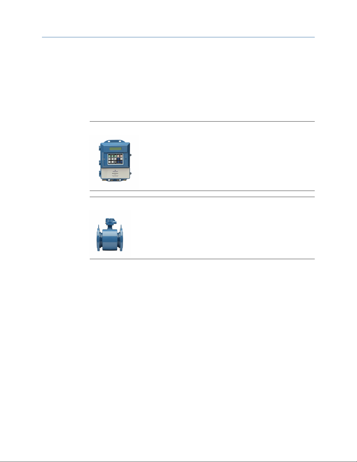
2.1 System description
The flowmeter consists of a sensor and a transmitter. The sensor is installed in-line with
the process piping; the transmitter is remotely mounted away from the sensor.
Figure 2-1: 8782 transmitter
Figure 2-2: MS sensor
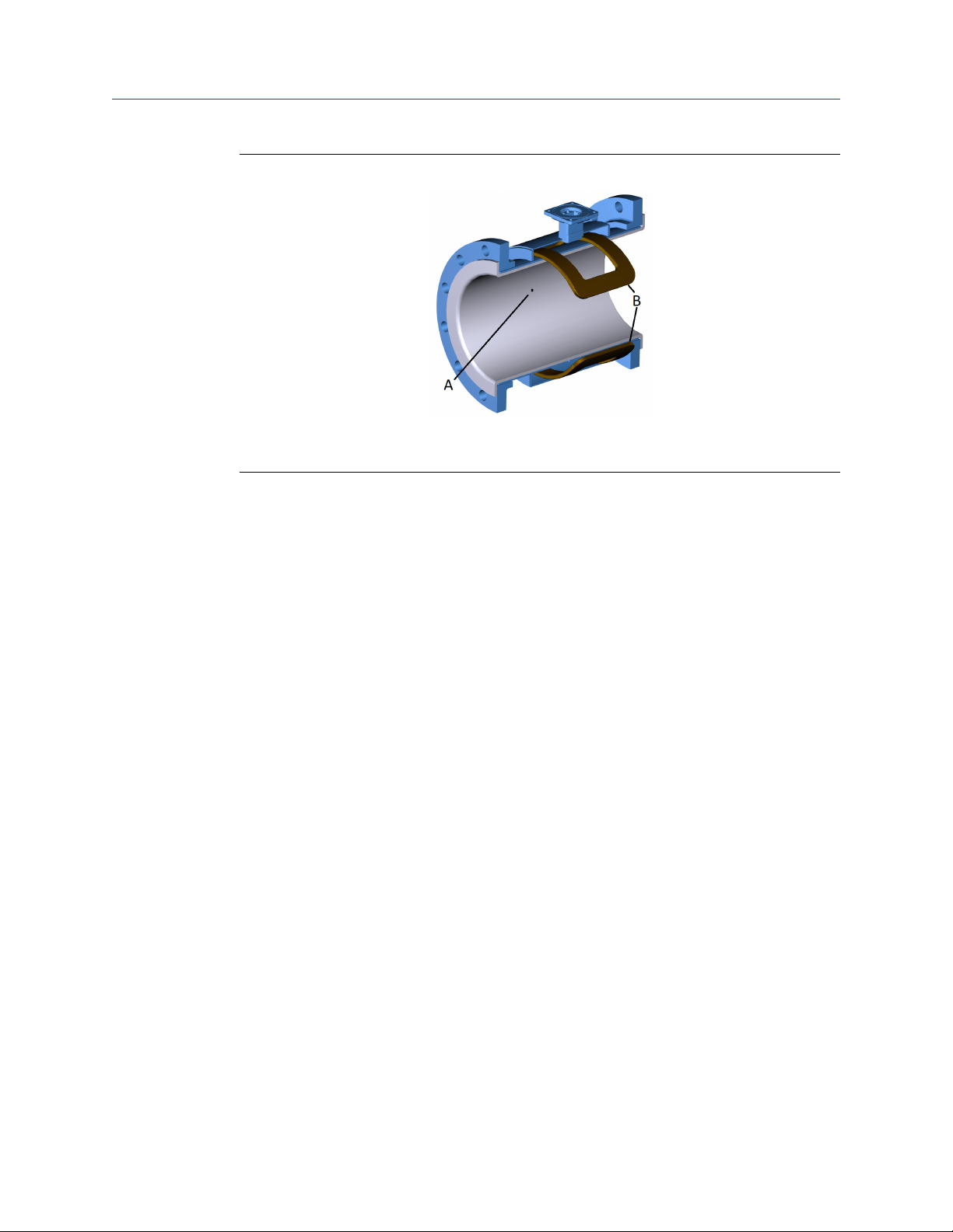
The flow sensor contains two magnetic coils located on opposite sides of the sensor. Two
electrodes, located perpendicular to the coils and opposite each other, make contact with
the liquid. The transmitter energizes the coils and creates a magnetic field. A conductive
liquid moving through the magnetic field generates an induced voltage at the electrodes.
This voltage is proportional to the flow velocity. The transmitter converts the voltage
detected by the electrodes into a flow reading. A cross-sectional view is show in Figure 2-3.
Reference Manual 11
Page 12
Introduction Reference Manual
November 2019 00809-0100-8782
Figure 2-3: Sensor cross section
A. Electrode
B. Coils
2.2 Product recycling/disposal
Recycling of equipment and packaging should be taken into consideration and disposed of
in accordance with local and national legislation/regulations.
12 Rosemount® 8782 Slurry Magnetic Flow Meter Transmitter with HART Protocol
Page 13

Reference Manual Sensor Installation
00809-0100-8782 November 2019
3 Sensor Installation
This chapter provides instructions for handling and installing the flow sensor with a
remotely mounted transmitter.
Related information
Remote Transmitter Installation
3.1 Handling and Lifting Safety
CAUTION
To reduce the risk of personal injury or damage to equipment, follow all lifting and
handling instructions.
• Handle all parts carefully to prevent damage. Whenever possible, transport the
system to the installation site in the original shipping container.
• PTFE-lined sensors are shipped with end covers that protect flange sealing surfaces
from both mechanical damage and normal unrestrained distortion. Remove the end
covers just before installation.
• Keep the shipping plugs in the conduit ports until you are ready to connect and seal
them. Appropriate care should be taken to prevent water ingress.
• The sensor should be supported by the pipeline. Pipe supports are recommended on
both the inlet and outlet sides of the sensor pipeline. There should be no additional
support attached to the sensor.
• Use proper PPE (Personal Protection Equipment) including safety glasses and safety
shoes.
• Do not lift the meter by holding the electronics housing or junction box.
• The sensor liner is vulnerable to handling damage. Never place anything through the
sensor for the purpose of lifting or gaining leverage. Liner damage can render the
sensor useless.
• Do not drop the device from any height.
Reference Manual 13
Page 14
Sensor Installation Reference Manual
November 2019 00809-0100-8782
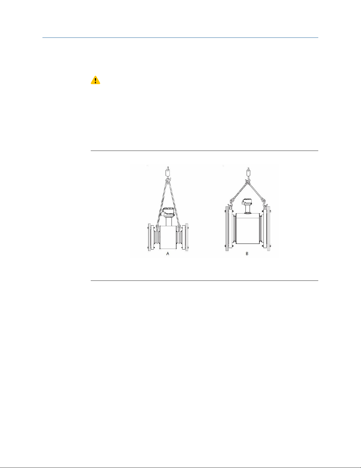
3.1.1 Lifting lugs
CAUTION
If provided, use the lifting lugs on each flange to handle the flow meter when it is
transported and lowered into place at the installation site. If lifting lugs are not
provided, the flow meter must be supported with a lifting sling on each side of the
housing.
• Standard pressure 3 inch through 36 inch flanged magnetic flowmeters come with
lifting lugs.
• High pressure (above 600#) 3 inch through 24 inch flanged magnetic flow meters
come with lifting lugs.
Figure 3-1: Example lifting without and with lifting lugs
A. Without lifting lugs
B. With lifting lugs
3.2 Location and Position
3.2.1 Environmental considerations
To ensure maximum transmitter life, avoid extreme temperatures and excessive vibration.
Typical problem areas include the following:
• Tropical/desert installations in direct sunlight
• Outdoor installations in arctic climates
3.2.2
Upstream and downstream piping
To ensure specified accuracy over widely varying process conditions, it is recommended to
install the sensor with a minimum of five straight pipe diameters upstream and two pipe
diameters downstream from the electrode plane.
14 Rosemount® 8782 Slurry Magnetic Flow Meter Transmitter with HART Protocol
Page 15
Reference Manual Sensor Installation
00809-0100-8782 November 2019
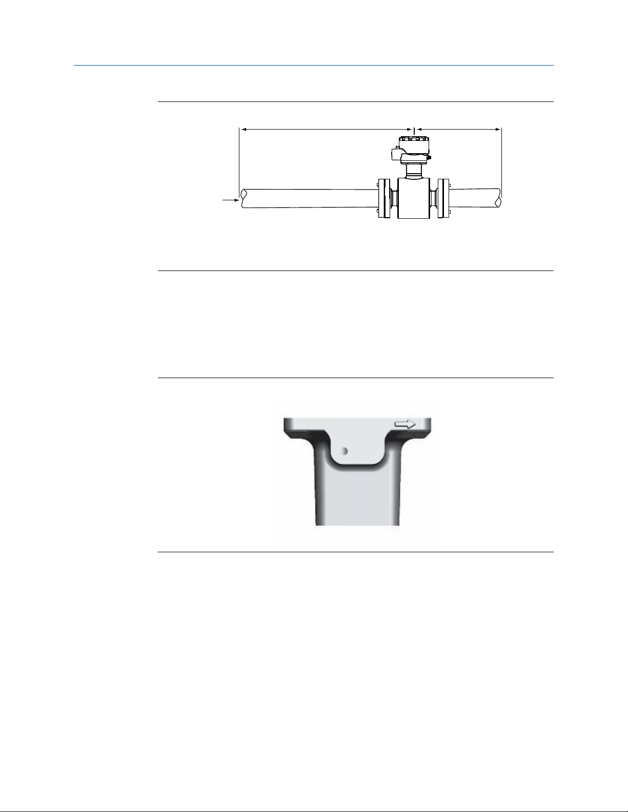
Figure 3-2: Upstream and downstream straight pipe diameters
3.2.3
A
C
A. Five pipe diameters (upstream)
B. Two pipe diameters (downstream)
C. Flow direction
Installations with reduced upstream and downstream straight runs are possible. In
reduced straight run installations, the meter may not meet accuracy specifications.
Reported flow rates will still be highly repeatable.
B
Flow direction
The sensor should be mounted so that the arrow points in the direction of flow.
Figure 3-3: Flow direction arrow
3.2.4
Reference Manual 15
Sensor piping location and orientation
The sensor should be installed in a location that ensures it remains full during operation.
Depending on where it is installed, orientation must also be considered.
• Vertical installation with upward process fluid flow keeps the cross-sectional area full,
regardless of flow rate.
• Horizontal installation should be restricted to low piping sections that are normally full.
Page 16
Sensor Installation Reference Manual
November 2019 00809-0100-8782
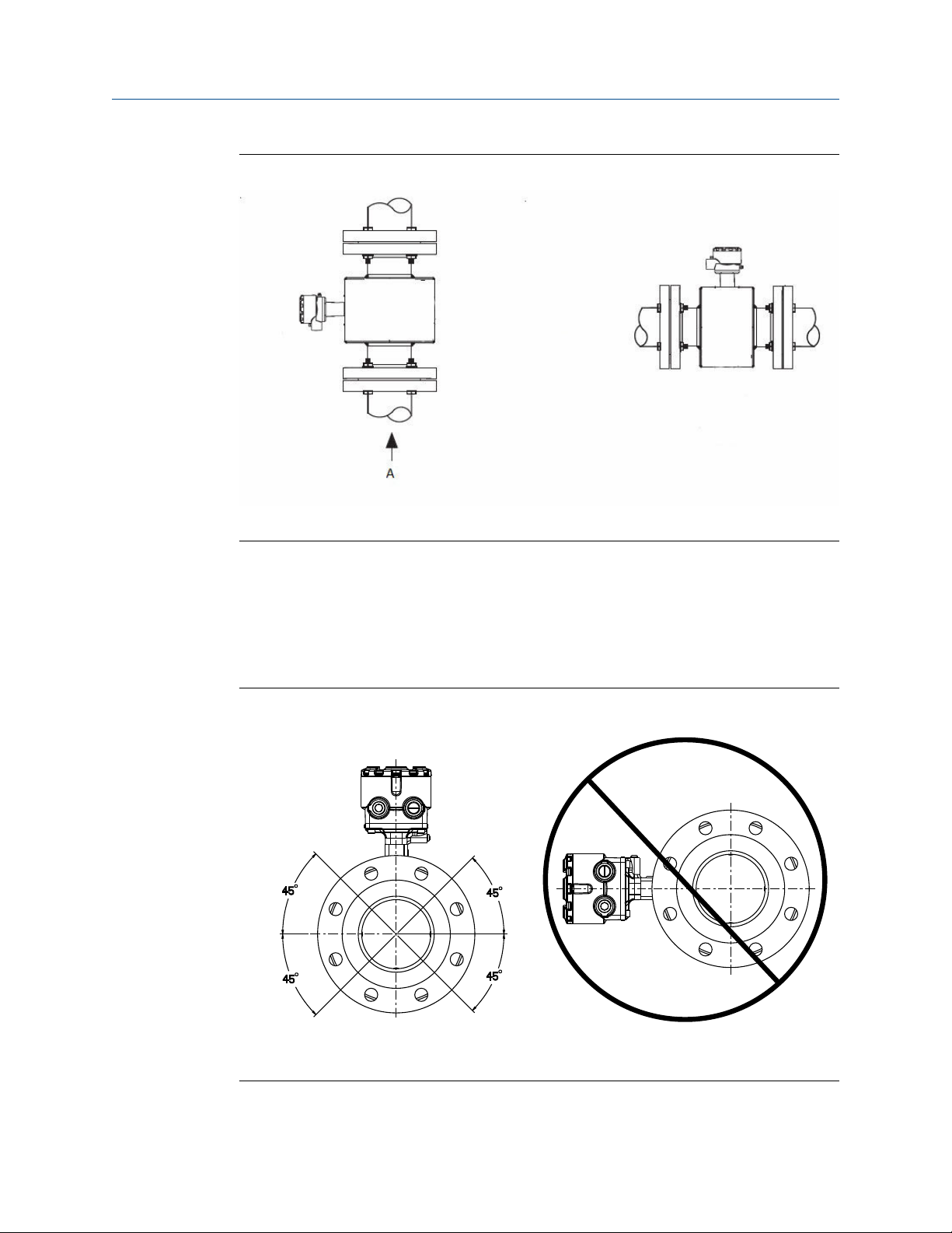
Figure 3-4: Sensor orientation
3.2.5
A. Flow direction
Electrode orientation
The electrodes in the sensor are properly oriented when the two measurement electrodes
are in the 3 and 9 o’clock positions or within 45 degrees from the horizontal, as shown on
the left side of Figure 3-5. Avoid any mounting orientation that positions the top of the
sensor at 90 degrees from the vertical position as shown on the right of Figure 3-5.
Figure 3-5: Electrode orientation
A
B
A. Correct orientation
B. Incorrect orientation
16 Rosemount® 8782 Slurry Magnetic Flow Meter Transmitter with HART Protocol
Page 17
Reference Manual Sensor Installation
00809-0100-8782 November 2019
The sensor may require a specific orientation to comply with Hazardous Area T-code
rating. Refer to the appropriate reference manual for any potential restrictions.
3.3 Sensor Installation
3.3.1 Flanged sensors
Gaskets
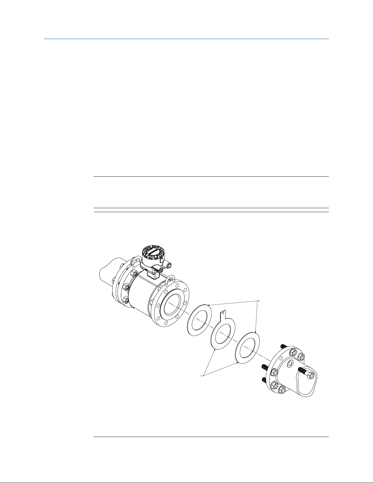
The sensor requires a gasket at each process connection. The gasket material must be
compatible with the process fluid and operating conditions. Gaskets are required on each
side of a grounding ring (see Figure 3-6). All other applications (including sensors with
lining protectors or a grounding electrode) require only one gasket on each process
connection.
Note
Metallic or spiral-wound gaskets should not be used as they will damage the liner face of
the sensor. If spiral wound or metallic gaskets are required for the application, lining
protectors must be used.
Figure 3-6: Gasket placement for flanged sensors
A
B
A. Grounding ring and gasket (optional)
B. Customer-supplied gasket
Reference Manual 17
Page 18

Sensor Installation Reference Manual
November 2019 00809-0100-8782
Bolts
Note
Do not bolt one side at a time. Tighten both sides simultaneously. Example:
1. Snug upstream
2. Snug downstream
3. Tighten upstream
4. Tighten downstream
Do not snug and tighten the upstream side and then snug and tighten the downstream
side. Failure to alternate between the upstream and downstream flanges when tightening
bolts may result in liner damage.
Suggested torque values by sensor line size and liner type are listed in Table 3-2 for ASME
B16.5 flanges and Table 3-3 or Table 3-4 for EN flanges. Consult the factory if the flange
rating of the sensor is not listed. Tighten flange bolts on the upstream side of the sensor in
the incremental sequence shown in Figure 3-7 to 20% of the suggested torque values.
Repeat the process on the downstream side of the sensor. For sensors with greater or
fewer flange bolts, tighten the bolts in a similar crosswise sequence. Repeat this entire
tightening sequence at 40%, 60%, 80%, and 100% of the suggested torque values.
If leakage occurs at the suggested torque values, the bolts can be tightened in additional
10% increments until the joint stops leaking, or until the measured torque value reaches
the maximum torque value of the bolts. Practical consideration for the integrity of the
liner often leads to distinct torque values to stop leakage due to the unique combinations
of flanges, bolts, gaskets, and sensor liner material.
Check for leaks at the flanges after tightening the bolts. Failure to use the correct
tightening methods can result in severe damage. While under pressure, sensor materials
may deform over time and require a second tightening 24 hours after the initial
installation.
Figure 3-7: Flange bolt torquing sequence
8
1
4
6
2
5
3
7
Prior to installation, identify the lining material of the flow sensor to ensure the suggested
torque values are applied.
18 Rosemount® 8782 Slurry Magnetic Flow Meter Transmitter with HART Protocol
Page 19
Reference Manual Sensor Installation
00809-0100-8782 November 2019
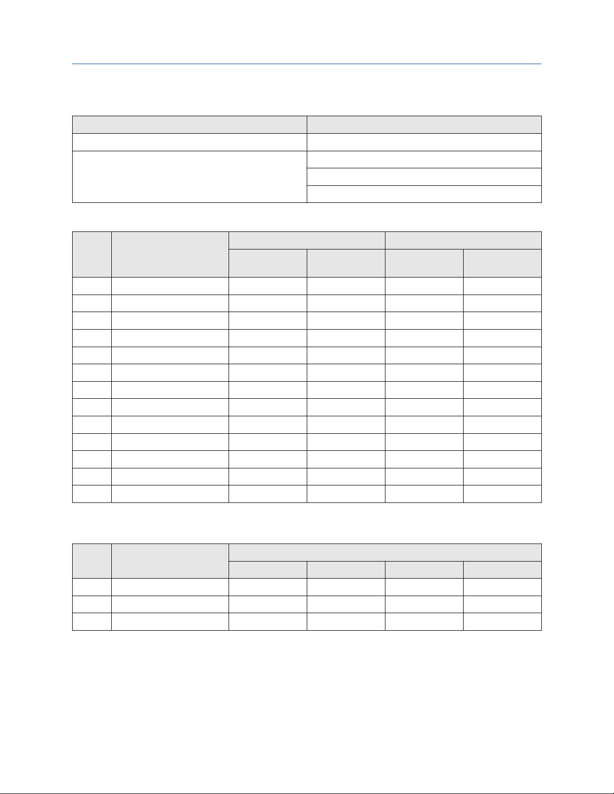
Table 3-1: Lining material
Fluoropolymer liners Other liners
T - PTFE P - Polyurethane
K - PFA+ N - Neoprene
L - Linatex (Natural Rubber)
D - Adiprene
Table 3-2: Suggested flange bolt torque values for Rosemount MS (ASME) sensors
Size
code
030 3 inch (80 mm) 34 35 23 23
040 4 inch (100 mm) 26 50 17 32
060 6 inch (150 mm) 45 50 30 37
080 8 inch (200 mm) 60 82 42 55
100 10 inch (250 mm) 55 80 40 70
120 12 inch (300 mm) 65 125 55 105
140 14 inch (350 mm) 85 110 70 95
160 16 inch (400 mm) 85 160 65 140
180 18 inch (450 mm) 120 170 95 150
200 20 inch (500 mm) 110 175 90 150
240 24 inch (600 mm) 165 280 140 250
300 30 inch (750 mm) 195 415 165 375
360 36 inch (900 mm) 280 575 245 525
Line size Fluoropolymer liners Other liners
Class 150 (lb‑ft) Class 300 (lb‑ft) Class 150 (lb‑ft) Class 300 (pound
feet)
Table 3-3: Suggested flange bolt torque values for Rosemount MS sensors with fluoropolymer liners
(EN 1092-1)
Size
code
030 3 inch (80 mm) N/A N/A N/A 50
040 4 inch (100 mm) N/A 50 N/A 70
060 6 inch (150mm) N/A 90 N/A 130
Reference Manual 19
Line size Fluoropolymer liners (in Newton-meters)
PN 10 PN 16 PN 25 PN 40
Page 20

Sensor Installation Reference Manual
November 2019 00809-0100-8782
Table 3-3: Suggested flange bolt torque values for Rosemount MS sensors with fluoropolymer liners
(EN 1092-1) (continued)
Size
code
080 8 inch (200 mm) 130 90 130 170
100 10 inch (250 mm) 100 130 190 250
120 12 inch (300 mm) 120 170 190 270
140 14 inch (350 mm) 160 220 320 410
160 16 inch (400 mm) 220 280 410 610
180 18 inch (450 mm) 190 340 330 420
200 20 inch (500 mm) 230 380 440 520
240 24 inch (600 mm) 290 570 590 850
Line size Fluoropolymer liners (in Newton-meters)
PN 10 PN 16 PN 25 PN 40
Table 3-4: Suggested flange bolt torque values for Rosemount MS sensors with non-fluoropolymer
liners (EN 1092-1)
Size
code
030 3 inch (80 mm) N/A N/A N/A 30
040 4 inch (100 mm) N/A 40 N/A 50
060 6 inch (150mm) N/A 60 N/A 90
Line size Non-fluoropolymer liners (in Newton-meters)
PN 10 PN 16 PN 25 PN 40
080 8 inch (200 mm) 90 60 90 110
100 10 inch (250 mm) 70 80 130 170
120 12 inch (300 mm) 80 110 130 180
140 14 inch (350 mm) 110 150 210 288
160 16 inch (400 mm) 150 190 280 410
180 18 inch (450 mm) 130 230 220 280
200 20 inch (500 mm) 150 260 300 350
240 24 inch (600 mm) 200 380 390 560
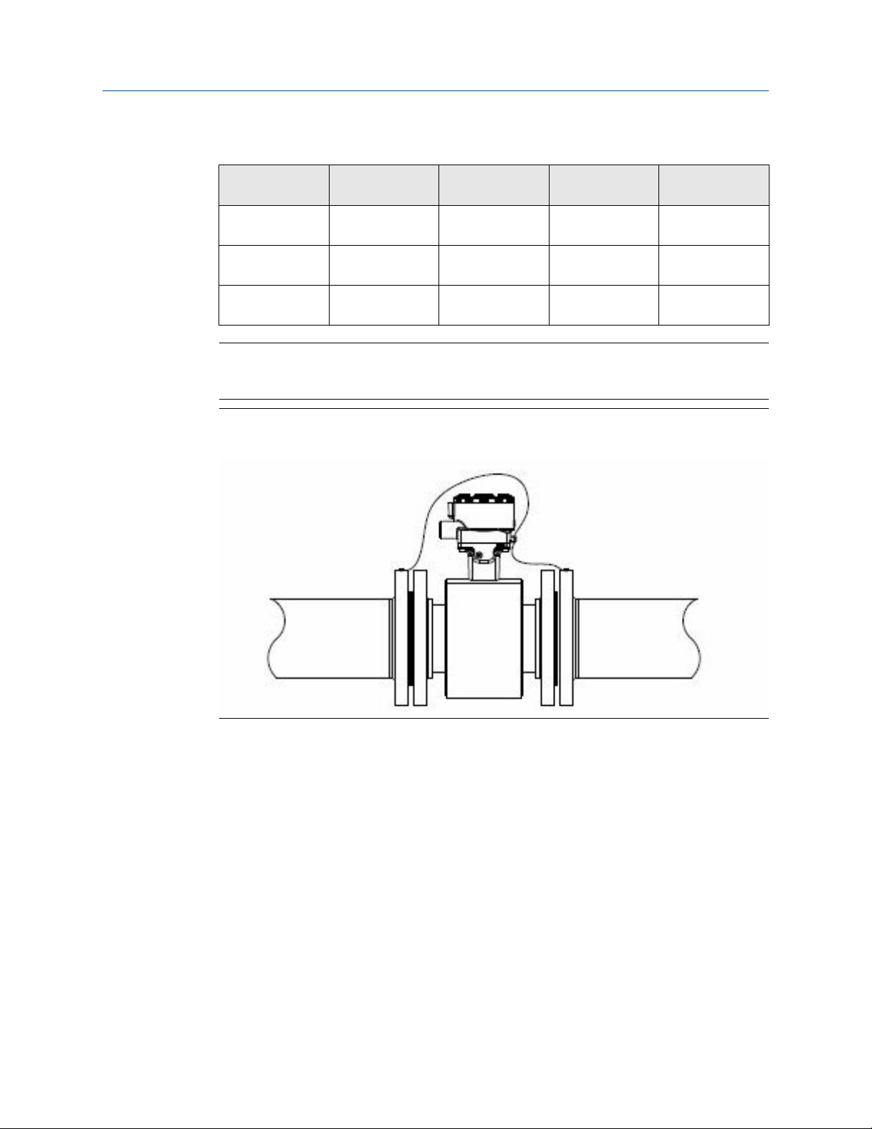
3.4 Process reference connection
The figures shown in this section illustrate best practice installations for process reference
connections only. For installations in conductive, unlined pipe it may be acceptable to use
one ground ring or one lining protector to establish a process reference connection. Earth
safety ground is also required as part of this installation, but is not shown in the figures.
Follow national, local, and plant electrical codes for safety ground.
Use Table 3-5 to determine which process reference option to follow for proper
installation.
20 Rosemount® 8782 Slurry Magnetic Flow Meter Transmitter with HART Protocol
Page 21
Reference Manual Sensor Installation
00809-0100-8782 November 2019
Table 3-5: Process reference options
Type of pipe Grounding
straps
Conductive
unlined pipe
Conductive lined
pipe
Non-conductive
pipe
See Figure 3-8 See Figure 3-9 See Figure 3-11 See Figure 3-9
Insufficient
grounding
Insufficient
grounding
Grounding rings Reference
electrode
See Figure 3-9 See Figure 3-8 See Figure 3-9
See Figure 3-10 Not
recommended
Lining protectors
See Figure 3-10
Note
For line sizes 10-inch and larger the ground strap may come attached to the sensor body
near the flange. See Figure 3-12.
Figure 3-8: Grounding straps in conductive unlined pipe or reference electrode in
lined pipe
Reference Manual 21
Page 22
Sensor Installation Reference Manual
November 2019 00809-0100-8782
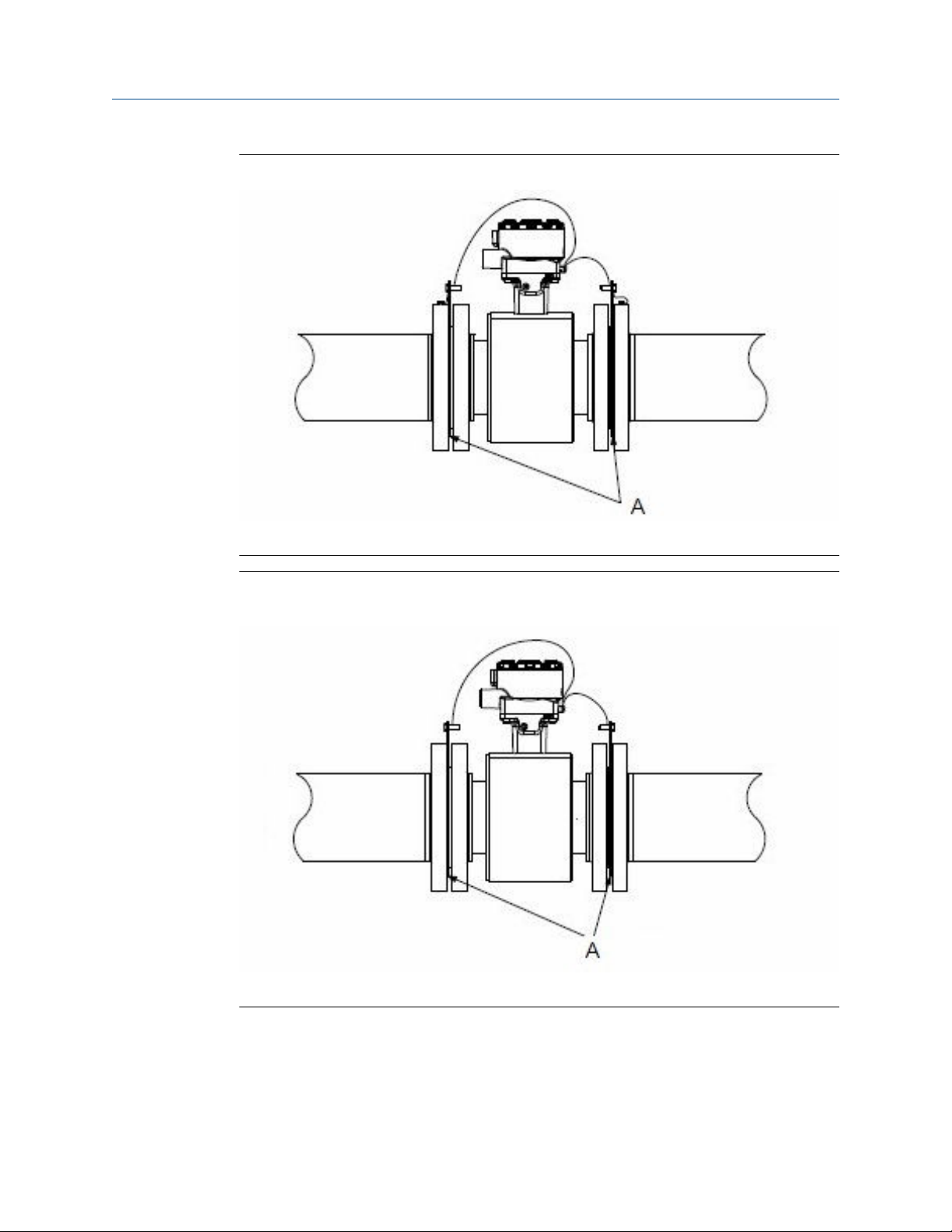
Figure 3-9: Grounding with grounding rings or lining protectors in conductive pipe
A. Grounding rings or lining protectors
Figure 3-10: Grounding with grounding rings or lining protectors in non-conductive
pipe
A. Grounding rings or lining protectors
22 Rosemount® 8782 Slurry Magnetic Flow Meter Transmitter with HART Protocol
Page 23
Reference Manual Sensor Installation
00809-0100-8782 November 2019
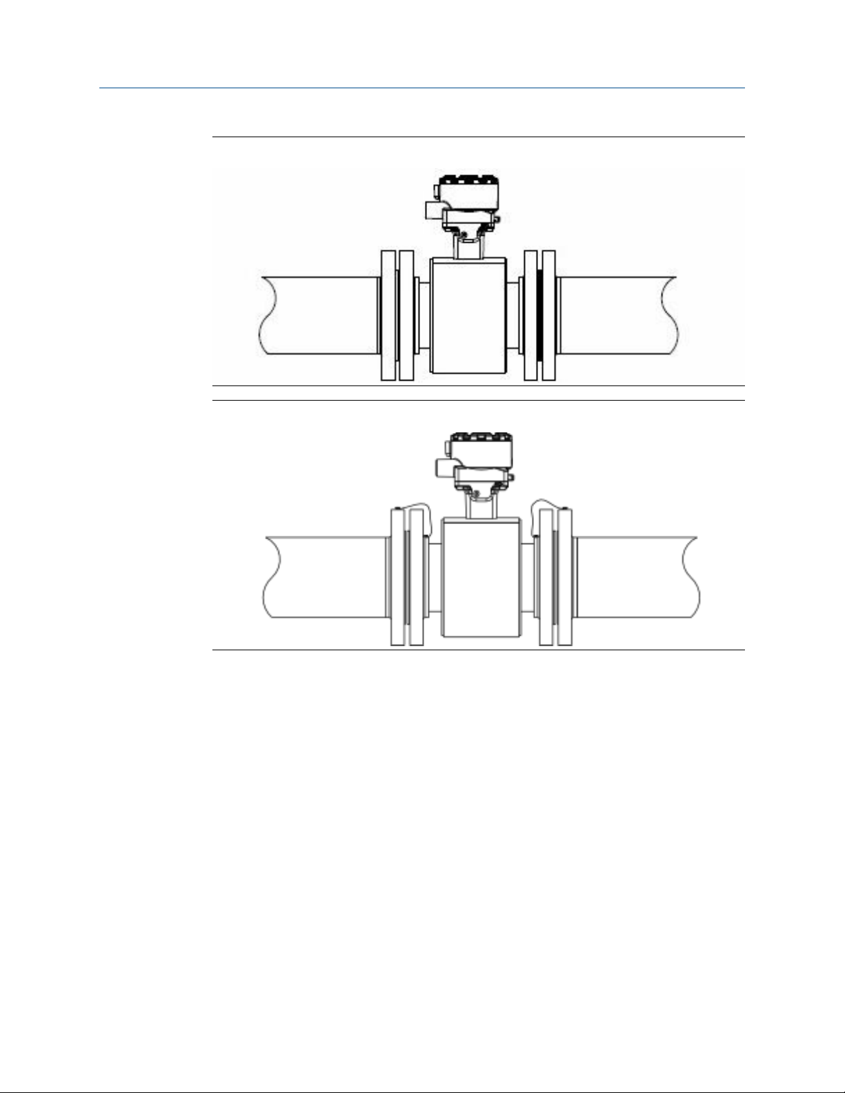
Figure 3-11: Grounding with reference electrode in conductive unlined pipe
Figure 3-12: Grounding for line sizes 10-in. and larger
Reference Manual 23
Page 24

Sensor Installation Reference Manual
November 2019 00809-0100-8782
24 Rosemount® 8782 Slurry Magnetic Flow Meter Transmitter with HART Protocol
Page 25

Reference Manual Remote Transmitter Installation
00809-0100-8782 November 2019
4 Remote Transmitter Installation
This chapter provides instructions for installing and wiring a remotely mounted
transmitter.
Related information
Sensor Installation
4.1 Pre-installation
Before installing the transmitter, there are several pre-installation steps that should be
completed to make the installation process easier:
• Identify options and configurations that apply to your application
• Set the hardware switches if necessary
• Consider mechanical, electrical, and environmental requirements
Note
Refer to Product Specifications for more detailed requirements.
Identify options and configurations
The typical transmitter installation includes a device power connection, a 4-20mA output
connection, and sensor coil and electrode connections. Other applications may require
one or more of the following configurations or options:
• Pulse output
• Discrete input/discrete output
• HART multidrop configuration
The transmitter may have up to four user-selectable hardware switches. These switches
set the alarm mode, internal/external analog power, internal/external pulse power, and
transmitter security. The standard configuration for these switches when shipped from the
factory is as follows:
Table 4-1: Hardware switch default settings
Setting Factory configuration
Alarm mode High
Internal/external analog power Internal
Internal/external pulse power External
Transmitter security Off
The analog power switch and pulse power switches are not available when ordered with
intrinsically safe output, ordering code B.
In most cases, it is not necessary to change the setting of the hardware switches. If the
switch settings need to be changed, refer to Hardware switches.
Reference Manual 25
Page 26
Remote Transmitter Installation Reference Manual
November 2019 00809-0100-8782
Be sure to identify any additional options and configurations that apply to the installation.
Keep a list of these options for consideration during the installation and configuration
procedures.
Mechanical considerations
The mounting site for the transmitter should provide enough room for secure mounting,
easy access to conduit entries, full opening of the transmitter covers, and easy readability
of the Local Operator Interface (LOI) screen (if equipped).
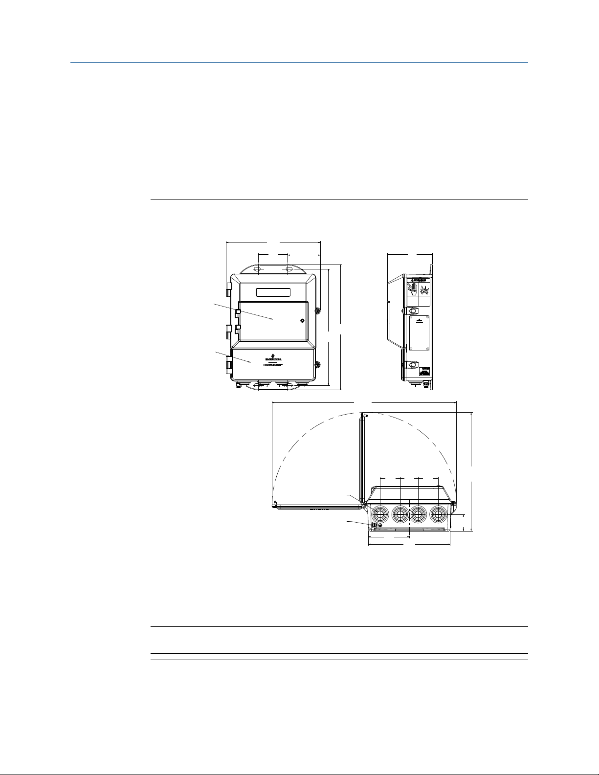
Figure 4-1: Rosemount 8782 Dimensional Drawing
9.0
(229)
(71)
2.8
(79)
3.1
C
12.0
(306)
11.2
(283)
D
(89)
3.5
A. Conduit entry,
½–14 NPT (4 places)
B. Ground lug
C. LOI keypad cover
D. Lower cover opens for electrical connections
Note
Dimensions are in inches (Millimeters)
17.7
(449)
11.4
(49)
1.9
1.7
1.9
(43)
(49)
(289)
A
B
3.9
(99)
7.8
(198)
(40)
1.6
26 Rosemount® 8782 Slurry Magnetic Flow Meter Transmitter with HART Protocol
Page 27
Reference Manual Remote Transmitter Installation
00809-0100-8782 November 2019
Electrical considerations
Before making any electrical connections to the transmitter, consider national, local, and
plant electrical installation requirements. Be sure to have the proper power supply,
conduit, and other accessories necessary to comply with these standards.
The transmitter requires external power. Ensure access to a suitable power source.
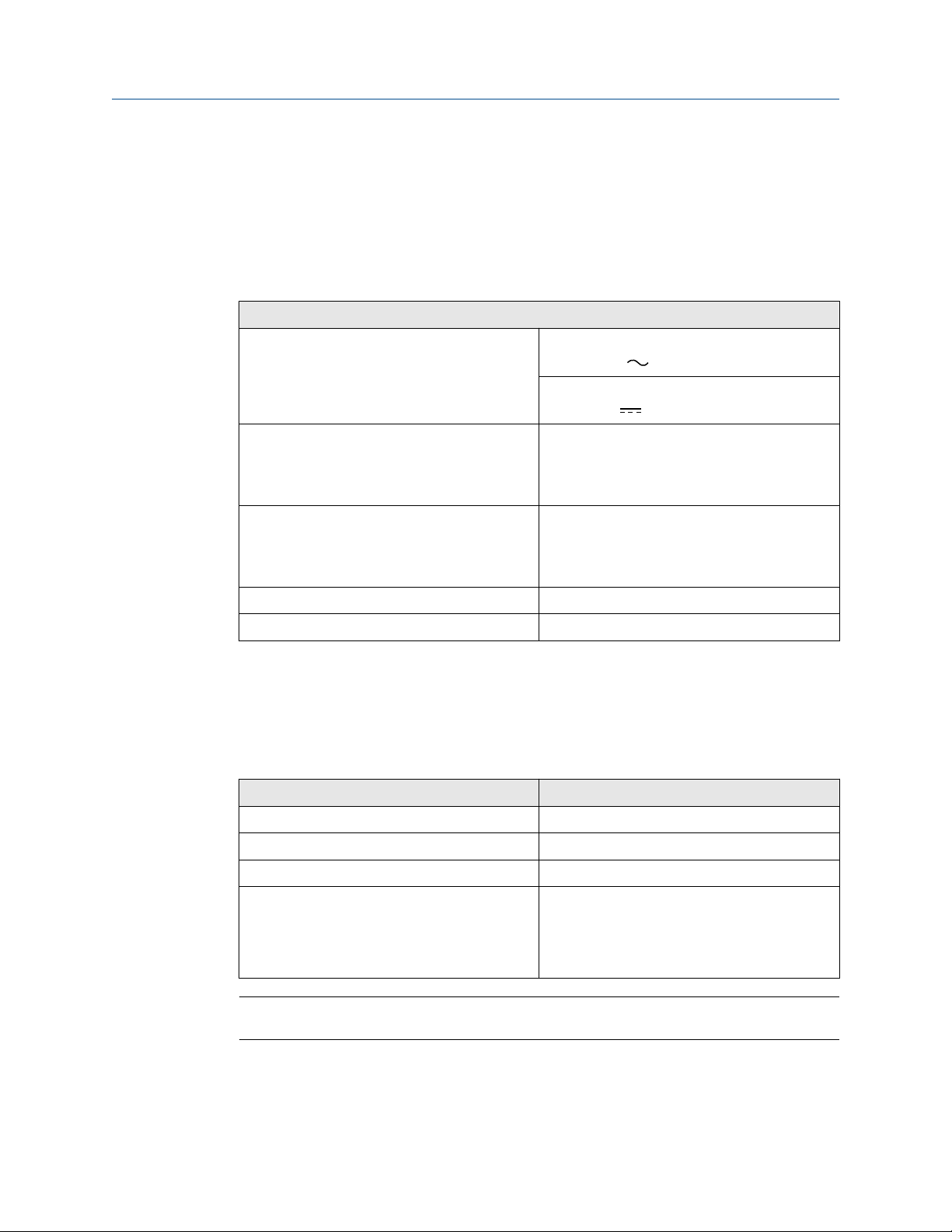
Table 4-2: Electrical Data
Electrical data
Power input AC power:
90–250 VAC ( ), 1.5A, 120 VA
Standard DC power:
12–42 VDC ( ), 8.6 A, 120 W
Pulsed circuit Internally powered (Active): Outputs up to
12 VDC, 12.1 mA, 73 mW
Externally powered (Passive): Input up to
28 VDC, 100 mA, 1 W
4-20mA output circuit Internally Powered (Active): Outputs up to
25 mA, 24 VDC, 600 mW
Externally Powered (Passive): Input up to 25 mA,
30 VDC, 750 mW
Um 250 V
Coil excitation output 2.0 A, 85 V max, 80 W max
Environmental considerations
Remote mounted transmitters may be installed in the control room to protect the
electronics from the harsh environment and to provide easy access for configuration or
service.
Table 4-3: Transmitter housing environmental ratings
Type Rating
Ingress protection IP66, IP69
NEMA 4X
Pollution Degree 2
Maximum altitude rating • 13,123 ft (4000 m) at rated input power
voltage (90–250 VAC)
• 16,404 ft (5000 m) at maximum input
power voltage of 150 VAC
Note
For complete environmental and other specifications, see Product Specifications.
Reference Manual 27
Page 28
Remote Transmitter Installation Reference Manual
November 2019 00809-0100-8782
4.2 Transmitter symbols
Caution symbol — check product
documentation for details
Protective conductor (grounding) terminal
4.3 Mounting
Wall mount transmitters are shipped with mounting hardware for use on a 2 inch (50 mm)
pipe or flat surface.
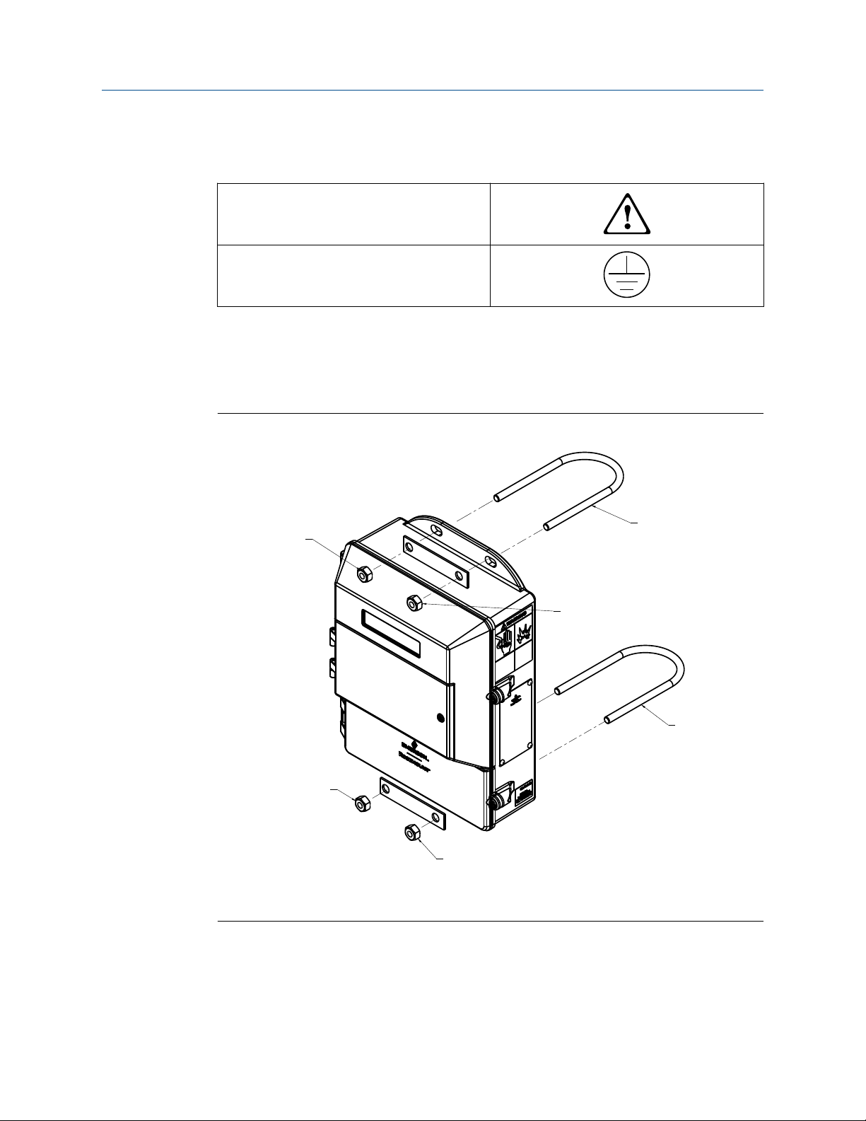
Figure 4-2: Mounting bracket
B
A. U-bolt
B. Fasteners
A
B
A
B
B
4.3.1
28 Rosemount® 8782 Slurry Magnetic Flow Meter Transmitter with HART Protocol
Pipe mounting
1. Assemble the hardware and transmitter housing on the pole as shown in Figure 4-2.
2. Tighten the nuts to ensure a snug fit.
Page 29

Reference Manual Remote Transmitter Installation
00809-0100-8782 November 2019
4.3.2 Surface mounting
Attach the transmitter to the mounting location using customer supplied mounting
screws. The installation of the transmitter shall be rated for four (4) times the weight of
the transmitter or 44lbs (20kgs).
4.4 Wiring
4.4.1 Conduit entries and connections
Transmitter conduit entries ports are ½"-14NPT as standard, M20 conduit connections will
use an adapter. Conduit connections should be made in accordance with national, local,
and plant electrical codes. Unused conduit entries should be sealed with the appropriate
certified plugs. The plastic shipping plugs do not provide ingress protection.
4.4.2
Conduit requirements
• For installations with an intrinsically safe electrode circuit, a separate conduit for the
coil cable and the electrode cable may be required. Refer to Product
Certifications.Refer to the product reference manual.
• For installations with non-intrinsically safe electrode circuit, a single dedicated conduit
run for the coil drive and electrode cable between the sensor and the remote
transmitter may be acceptable. Removal of the barriers for intrinsic safety isolation is
permitted for non-intrinsically safe electrode installations.
• Bundled cables from other equipment in a single conduit are likely to create
interference and noise in the system. See Figure 4-3.
• Electrode cables should not be run together in the same cable tray with power cables.
• Output cables should not be run together with power cables.
• Select conduit size appropriate to feed cables through to the flowmeter.
Reference Manual 29
Page 30
Remote Transmitter Installation Reference Manual
November 2019 00809-0100-8782
Figure 4-3: Best practice conduit preparation
4.4.3
A
C D E
B
A
A
A. Safety ground
B. Power
C. Coil
D. Output
E. Electrode
Sensor to transmitter wiring
Remote cable kits can be ordered directly using the kit numbers shown in Table 4-4 and
Table 4-5. Equivalent Alpha cable part numbers are also provided as an alternative. To
order cable, specify length as quantity desired. Equal length of component cables is
required.
Examples:
• 25 feet = Qty (25) 08732-0065-0001
• 25 meters = Qty (25) 08732-0065-0002
Table 4-4: Component cable kits - standard temperature (-20°C to 75°C)
Cable kit # Description Individual cable Alpha p/n
08732-0065-0001 (feet) Kit, component cables, Std temp
(includes Coil and Electrode)
08732-0065-0002 (meters) Kit, component cables, Std temp
(includes Coil and Electrode)
30 Rosemount® 8782 Slurry Magnetic Flow Meter Transmitter with HART Protocol
Coil
Electrode
Coil
Electrode
2442C
2413C
2442C
2413C
Page 31

Reference Manual Remote Transmitter Installation
00809-0100-8782 November 2019
Table 4-4: Component cable kits - standard temperature (-20°C to 75°C) (continued)
Cable kit # Description Individual cable Alpha p/n
08732-0065-0003 (feet) Kit, component cables, Std temp
(includes Coil and I.S. Electrode)
08732-0065-0004 (meters) Kit, component cables, Std temp
(includes Coil and I.S. Electrode)
Coil
Instrinsically Safe
Blue Electrode
Coil
Instrinsically Safe
Blue Electrode
2442C
Not available
2442C
Not available
Table 4-5: Component cable kits - extended temperature (-50°C to 125°C)
Cable kit # Description Individual cable Alpha p/n
08732-0065-1001 (feet) Kit, Component Cables, Ext Temp.
(includes Coil and Electrode)
08732-0065-1002 (meters) Kit, Component Cables, Ext Temp.
(includes Coil and Electrode)
08732-0065-1003 (feet) Kit, Component Cables, Ext Temp.
(includes Coil and I.S. Electrode)
08732-0065-1004 (meters) Kit, Component Cables, Ext Temp.
(includes Coil and I.S. Electrode)
Coil
Electrode
Coil
Electrode
Coil
Intrinsically Safe
Blue Electrode
Coil
Intrinsically Safe
Blue Electrode
Not available
Not available
Not available
Not available
Not available
Not available
Not available
Not available
Cable requirements
Shielded twisted pairs or triads must be used. See Figure 4-4. Cable lengths should be
limited to less than 300 feet (100 m).
Reference Manual 31
Page 32

Remote Transmitter Installation Reference Manual
November 2019 00809-0100-8782
Figure 4-4: Individual component cables
A B
1 2
C
3
D
E
F
A. Coil drive
B. Electrode
C. Twisted, stranded, insulated 14 AWG conductors
D. Drain
E. Overlapping foil shield
F. Outer jacket
G. Twisted, stranded, insulated 20 AWG conductors
• 1 = Red
3
17 18 19
G
• 2 = Blue
• 3 = Drain
• 17 = Black
• 18 = Yellow
• 19 = White
Cable preparation
Prepare the ends of the coil drive and electrode cables as shown in Figure 4-5. Remove
only enough insulation so that the exposed conductor fits completely under the terminal
connection. Best practice is to limit the unshielded length (D) of each conductor to less
than one inch. Excessive removal of insulation may result in an unwanted electrical short
to the transmitter housing or other terminal connections. Excessive unshielded length, or
failure to connect cable shields properly, may also expose the unit to electrical noise,
resulting in an unstable meter reading.
32 Rosemount® 8782 Slurry Magnetic Flow Meter Transmitter with HART Protocol
Page 33

B
C
A
Reference Manual Remote Transmitter Installation
00809-0100-8782 November 2019
Figure 4-5: Cable ends
A. Unshielded length
B. Coil
C. Electrode
WARNING
Shock hazard! Potential shock hazard across remote junction box terminals 1 and 2
(85V).
WARNING
Explosion hazard! Electrodes exposed to process. Use only compatible transmitter and
approved installation practices. For process temperatures greater than 284°F (140°C),
use a wire rated for 257°F (125°C).
Reference Manual 33
Page 34

Remote Transmitter Installation Reference Manual
November 2019 00809-0100-8782
Remote junction box terminal blocks
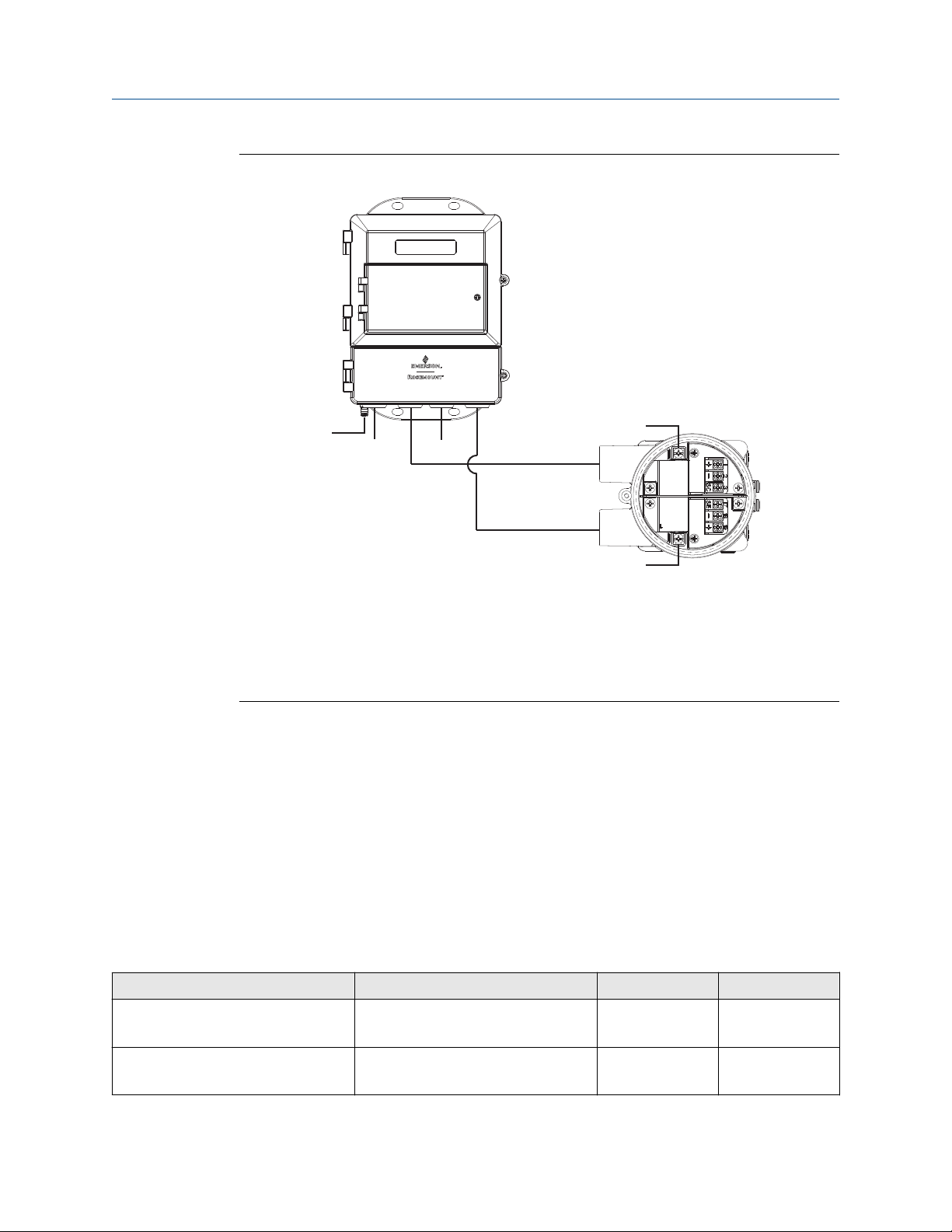
Figure 4-6: Remote junction box views
B
A
A. Sensor
B. Transmitter
Note
Junction box appearance and configuration may vary, but terminal numbering is
consistent for all junction box types.
Table 4-6: Sensor/transmitter wiring
Wire color Sensor terminal Transmitter terminal
Red 1 1
Blue 2 2
Coil drain 3 or float 3
Black 17 17
Yellow 18 18
White 19 19
Electrode drain
or float
34 Rosemount® 8782 Slurry Magnetic Flow Meter Transmitter with HART Protocol
Page 35

Reference Manual Remote Transmitter Installation
00809-0100-8782 November 2019
4.4.4 Wiring sensor to transmitter
Figure 4-7: Wiring using component cable
Reference Manual 35
Page 36

Remote Transmitter Installation Reference Manual
November 2019 00809-0100-8782
4.4.5 Power and I/O terminal blocks
Open the bottom cover of the transmitter to access the terminal block.
Note
To connect pulse output and/or discrete input/output, refer to Advanced installation
details, and for installations with intrinsically safe outputs, refer to Product Certifications.
Figure 4-8: Terminal blocks
N 1 2 9 10 5 6 19 18
L1 3 11 12 7 8 17
Table 4-7: Power and I/O terminals
Terminal number AC version DC version
1 Coil Positive Coil Positive
2 Coil Negative Coil Negative
3 Coil Shield Coil Shield
5 + Pulse + Pulse
6 – Pulse – Pulse
(1)
7
(1)
8
(2)
9
(2)
10
(2)
11
(2)
12
17 Electrode Reference Electrode Reference
18 Electrode Negative Electrode Negative
19 Electrode Positive Electrode Positive
N AC (Neutral) DC (–)
Analog HART Analog HART
Analog HART Analog HART
+ Discrete In/Out 2 + Discrete In/Out 2
– Discrete In/Out 2 – Discrete In/Out 2
+ Discrete In/Out 1 + Discrete In/Out 1
– Discrete In/Out 1 – Discrete In/Out 1
L1 AC L1 DC (+)
(1) Note Polarity: Internally Powered, Terminal 7 (–) Analog HART, Terminal 8 (+) Analog HART.
Externally Powered, Terminal 7 (+) Analog HART, Terminal 8 (–) Analog HART
(2) Only available with ordering code AX.
36 Rosemount® 8782 Slurry Magnetic Flow Meter Transmitter with HART Protocol
Page 37

Reference Manual Remote Transmitter Installation
00809-0100-8782 November 2019
4.4.6 Powering the transmitter
Before connecting power to the transmitter, be sure to have the necessary electrical
supplies and required power source:
Wire the transmitter according to national, local, and plant electrical requirements.
If installing in a hazardous location, verify that the meter has the appropriate hazardous
area approval. The hazardous area ratings are located on the main nameplate tag attached
to the side of the transmitter.
Supply wire requirements
Use 10–18 AWG wire rated for the proper temperature of the application. For wire 10–14
AWG use lugs or other appropriate connectors. For connections in ambient temperatures
above 122 °F (50 °C), use a wire rated for 194 °F (90 °C). For DC powered transmitters with
extended cable lengths, verify that there is a minimum of 12VDC at the terminals of the
transmitter with the device under load.
Electrical disconnect requirements
Connect the device through an external disconnect or circuit breaker per national and
local electrical code.
Overcurrent protection
The transmitter requires overcurrent protection of the supply lines. Fuse rating and
compatible fuses are shown in Line power fuses.
Installation category
The installation category for the transmitter is OVERVOLTAGE CAT II.
AC power system installation requirements
Neutral-earth power requirements
• The power system must have a neutral that is locally bonded to earth, or provide both
line to earth and neutral to earth voltage limitation of no more than 250 VAC.
Power line impedance
• Sources of inductance on the AC power system, such as isolation transformers, must be
limited to less than 1 mH at 120 VAC, and 2 mH at 240 VAC.
Power terminals
For AC powered transmitter (90–250VAC, 50/60 Hz):
• Connect AC Neutral to Terminal N and AC Line to Terminal L1.
For DC powered transmitter:
• Connect negative to Terminal N and positive to Terminal L1.
• DC powered units may draw up to 8.6 A.
Reference Manual 37
Page 38

Remote Transmitter Installation Reference Manual
November 2019 00809-0100-8782
Power supply
• 90 VAC to 250 VAC @ 50/60Hz.
— Overvoltage Category II
— Single Phase Earthed Neutral System
• 12 VDC to 42 VDC.
Note
For applications with sensors greater than 14 inch (350 mm) and process temperature
greater than 212 °F (100 °C), consult an Emerson Flow representative (see back page)
when applying less than 18 VDC to power terminals.
Line power fuses
Power supply type Rating Manufacturer part number
90–250 VAC 2.5 A, 250 VAC Bel Fuse 3AG 2.5-R, Littlefuse 312025, or
equivalent
12–42 VDC 12 A, 250 VAC Bel Fuse 3AB 12-R, Littlefuse 314012, or
equivalent
Power consumption
• 90 VAC to 250 VAC: 120 VA maximum
• 12 VDC to 42 VDC: 120 W maximum
Inrush/Start-up current
The power system must be capable of supporting inrush/start-up currents of:
• AC supply: Maximum 7 A (<5 ms)
• DC supply: Maximum 13 A (<5 ms)
Covers
Use the transmitter lower door screw to secure the terminal compartment after the
instrument has been wired. Follow these steps to ensure the housing is properly sealed to
meet ingress protection requirements:
1. Ensure all wiring is complete and close the lower door.
2. Tighten the lower door screw until the lower door is tight against the housing.
Metal to metal contact of the screw bosses is required to ensure a proper seal.
Note
Application of excessive torque may strip the threads or break the screw.
3. Verify the lower door is secure.
4.4.7
38 Rosemount® 8782 Slurry Magnetic Flow Meter Transmitter with HART Protocol
Analog output
The analog output signal is a 4-20 mA current loop. Depending on the IS output option,
the loop can be powered internally or externally via a hardware switch located on the front
of the electronics stack. The switch is set to internal power when shipped from the factory.
Page 39

Reference Manual Remote Transmitter Installation
00809-0100-8782 November 2019
Intrinsically safe analog output requires a shielded twisted pair cable. For HART
communication, a minimum resistance of 250 ohms is required. It is recommended to use
individually shielded twisted pair cable. The minimum conductor size is 24 AWG
(0.51 mm) diameter for cable runs less than 5,000 feet (1,500 m) and 20 AWG (0.81 mm)
diameter for longer distances.
Note
For more information about the analog output characteristics, see Output signals.
Figure 4-9: Analog output wiring
A B
A. Terminal #7
B. Terminal #8
Note
Terminal polarity for the analog output is reversed between internally and externally
powered.
Table 4-8: Terminal assignment by power source type
Power source Terminal #7 Terminal #8
Internal 4–20 mA negative (–) 4–20 mA positive (+)
External 4–20 mA positive (+) 4–20 mA negative (–)
Reference Manual 39
Page 40

Remote Transmitter Installation Reference Manual
November 2019 00809-0100-8782
Figure 4-10: Analog loop load limitations
600
A
C
0
10.8 30
B
A. Load (ohms)
B. Power supply (volts)
C. Operating region
• R
= 31.25 (Vps–10.8)
max
• Vps = power supply voltage (volts)
• R
= maximum loop resistance (ohms)
max
40 Rosemount® 8782 Slurry Magnetic Flow Meter Transmitter with HART Protocol
Page 41

Reference Manual Basic Configuration
00809-0100-8782 November 2019
5 Basic Configuration
Once the flow meter is installed and power has been supplied, the transmitter must be
configured using the LOI, if equipped, or a configuration tool, such as ProLink III Software.
Descriptions of more advanced functions are included in Advanced Configuration
Functionality.
5.1 Basic Setup
Tag
Tag is the quickest and shortest way of identifying and distinguishing between
transmitters. Transmitters can be tagged according to the requirements of your
application. The transmitter supports the 8 character Tag and the 32 character Long Tag.
Both parameters are available for configuration.
Calibration number
The sensor calibration number is a 16-digit number generated at the factory during flow
calibration, is unique to each sensor, and is located on the sensor nameplate.
Flow units (PV)
The flow units variable specifies the format in which the flow rate will be displayed. Units
should be selected to meet your particular metering needs. See Measurement units.
Line size
The line size (sensor size) must be set to match the actual sensor connected to the
transmitter. The size must be specified in inches.
Upper range value (URV)
The URV sets the 20 mA point for the analog output. This value is typically set to full-scale
flow. The units that appear will be the same as those selected under the flow units
parameter. The URV may be set between –39.3 ft/s to 39.3 ft/s (–12 m/s to 12m/s). There
must be at least 1 ft/s (0.3 m/s) span between the URV and LRV.
Note
If entering a negative number, the minus sign must be entered in the furthest left position
on the LOI.
Lower range value (LRV)
The LRV sets the 4 mA point for the analog output. This value is typically set to zero flow.
The units that appear will be the same as those selected under the flow units parameter.
The LRV may be set between –39.3 ft/s to 39.3 ft/s (–12 m/s to 12m/s). There must be at
least 1 ft/s (0.3 m/s) span between the URV and LRV.
Note
If entering a negative number, the minus sign must be entered in the furthest left position
on the LOI.
Reference Manual 41
Page 42

Basic Configuration Reference Manual
November 2019 00809-0100-8782
Auto zero
The Auto zero is recommended for optimum performance when a flow meter is initially
installed, and it typically does not need to be performed again. However, if process
conditions drastically change, a new Auto zero is recommended. The sensor must be filled
completely with process fluid at zero flow. For more information, see Auto zero.
5.2 Local operator interface (LOI)
To access the transmitter menu, press the XMTR MENU key. Use the UP, DOWN, LEFT(E),
and RIGHT arrows to navigate the menu structure.
A complete map of the LOI menu structure is shown in LOI Menu trees.
The display can be locked to prevent unintentional configuration changes. The display lock
can be activated through a HART communication device, or by holding the UP arrow for
three seconds and then following the on-screen instructions.
5.3 Other configuration tools
Table 5-1 shows the approximate category or location of basic setup parameters for
typical configuration tools.
Table 5-1: Approximate setup category/locations for typical configuration tools
Function Category/Location
Flow Units
PV Upper Range Value (URV) Basic Setup → AO
PV Lower Range Value (LRV) Basic Setup → AO
Auto zero
Calibration Number Basic Setup → Setup
Line Size Basic Setup → Setup
Tag Device Info → Identification
Long Tag Device Info → Identification
Basic Setup
Diagnostics
5.4 Measurement units
Table 5-2: Volumetric flow units
gal/sec gal/min gal/hr gal/day
L/sec L/min L/hr L/day
ft3/sec ft3/min ft3/hr ft3/day
cm3/min
m3/sec m3/min m3/hr m3/day
42 Rosemount® 8782 Slurry Magnetic Flow Meter Transmitter with HART Protocol
Page 43

Reference Manual Basic Configuration
00809-0100-8782 November 2019
Table 5-2: Volumetric flow units (continued)
Impgal/sec Impgal/min Impgal/hr Impgal/day
B31/sec (1 barrel = 31
gallons)
B42/sec (1 barrel = 42
gallons)
B31/min (1 barrel = 31
gallons)
B42/min (1 barrel = 42
gallons)
B31/hr (1 barrel = 31
gallons)
B42/hr (1 barrel = 42
gallons)
B31/day (1 barrel = 31
gallons)
B42/day (1 barrel = 42
gallons)
Table 5-3: Mass flow units
lbs/sec lbs/min lbs/hr lbs/day
kg/sec kg/min kg/hr kg/day
(s) tons/min (s) tons/hr (s) tons/day
(m) tons/min (m) tons/hr (m) tons/day
Table 5-4: Velocity units
ft/sec m/sec
Reference Manual 43
Page 44

Basic Configuration Reference Manual
November 2019 00809-0100-8782
44 Rosemount® 8782 Slurry Magnetic Flow Meter Transmitter with HART Protocol
Page 45

Reference Manual Advanced installation details
00809-0100-8782 November 2019
6 Advanced installation details
6.1 Hardware switches
The electronics are equipped with four user-selectable hardware switches. These switches
set the Alarm Mode, Internal/External Analog Power, Transmitter Security, and Internal/
External Pulse Power.
Definitions of these switches and their functions are provided below. To change the
settings, see below.
6.1.1 Alarm mode
If an event occurs that would trigger an alarm in the electronics, the analog output will be
driven high or low, depending on the switch position. The switch is set in the HIGH
position when shipped from the factory. Refer to Table 8-1 and Table 8-2 for analog
output values of the alarm.
6.1.2
6.1.3
Transmitter security
The SECURITY switch allows the user to lock out any configuration changes attempted on
the transmitter.
• When the security switch is in the ON position, the configuration can be viewed but no
changes can be made.
• When the security switch is in the OFF position, the configuration can be viewed and
changes can be made.
The switch is in the OFF position when the transmitter is shipped from the factory.
Note
The flow rate indication and totalizer functions remain active when the SECURITY switch is
in either position.
Internal/external analog power
Note
With output option code B, the analog output can only be externally powered and there is
no ANALOG switch.
The 4–20 mA loop can be powered internally by the transmitter or externally by an
external power supply. The ANALOG switch determines the source of the 4–20 mA loop
power.
• When the switch is in the INTERNAL position, the 4–20 mA loop is powered internally
by the transmitter.
• When the switch is in the EXTERNAL position, a 10-30 VDC external power supply is
required. For more information about 4–20 mA external power, see Analog output.
Reference Manual 45
Page 46

Advanced installation details Reference Manual
November 2019 00809-0100-8782
The switch is in the INTERNAL position when the transmitter is shipped from the factory.
Note
External power is required for multidrop configurations.
6.1.4 Internal/external pulse power
Note
With output option code B, the pulse output can only be externally powered and there is
no PULSE switch.
The pulse loop can be powered internally by the transmitter or externally or by an external
power supply. The PULSE switch determines the source of the pulse loop power.
• When the switch is in the INTERNAL position, the pulse loop is powered internally by
the transmitter.
• When the switch is in the EXTERNAL position, a 5–28 VDC external supply is required.
For more information about pulse external power, see Connect pulse output.
The switch is in the EXTERNAL position when the transmitter is shipped from the factory.
6.1.5
Changing hardware switch settings
Note
The hardware switches are located on the top side of the electronics board and changing
their settings requires opening the electronics housing. If possible, carry out these
procedures away from the plant environment in order to protect the electronics.
46 Rosemount® 8782 Slurry Magnetic Flow Meter Transmitter with HART Protocol
Page 47

Reference Manual Advanced installation details
00809-0100-8782 November 2019
Figure 6-1: Electronics stack and hardware switches
A
B
C
A. Alarm level
B. Analog and pulse internal and external power
C. Security
Note
Review safety information in Hazard messages before accessing the transmitter
electronics.
1. Place the control loop into manual control.
2. Disconnect power to the transmitter
3. Open the electronics compartment cover.
4. Identify the location of each switch (see Figure 6-1 ).
5. Change the setting of the desired switches with a small, non-metallic tool.
6. Close the electronics compartment cover. See Powering the transmitter for details
on the covers.
7. Return power to the transmitter and verify the flow measurement is correct.
8. Return the control loop to automatic control.
6.2 Pulse output and discrete input/outputs
There are three additional loop connections available on the Transmitter:
• Pulse output - used for external or remote totalization (see Pulse output).
• Discrete I/O Channel 1 can be configured as discrete input or discrete output (see
Discrete input/output).
Reference Manual 47
Page 48

Advanced installation details Reference Manual
November 2019 00809-0100-8782
• Discrete I/O Channel 2 can be configured as discrete output only (see Discrete input/
output).
6.2.1 Connect pulse output
The pulse output function provides a galvanically isolated frequency signal that is
proportional to the flow through the sensor. The signal is typically used in conjunction
with an external totalizer or control system.
Note
• With output option code A, the pulse output can be internally or externally powered,
and the PULSE switch must be set accordingly (the default setting is EXTERNAL).
• With output option code B, the pulse output can only be externally powered and there
is no PULSE switch. See Internal/external pulse power.
External power supply
For an externally powered pulse output, the following requirements apply:
• Supply voltage: 5 to 28 VDC
• Maximum current: 100 mA
• Maximum power: 1.0 W
• Load resistance: 200 to 10k Ohms (typical value 1k Ohms). Refer to the figure
indicated:
Output option code
A 5-28 VDC See Figure 6-2
B 5 VDC See Figure 6-3
B 12 VDC See Figure 6-4
B 24 VDC See Figure 6-5
• Pulse mode: Fixed pulse width or 50% duty cycle
• Pulse duration: 0.1 to 650 ms (adjustable)
• Maximum pulse frequency:
— Output option code A is 10,000 Hz
— Output option code B is 5000 Hz
• FET switch closure: solid state switch
Supply voltage Resistance vs cable length
48 Rosemount® 8782 Slurry Magnetic Flow Meter Transmitter with HART Protocol
Page 49

Reference Manual Advanced installation details
00809-0100-8782 November 2019
Figure 6-2: Output Option Code A—Maximum Frequency vs. Cable Length
A. Frequency (Hz)
B. Cable length (feet)
Figure 6-3: Output Option Code B—VDC Supply
A. Resistance (Ω)
B. Cable length (feet)
At 5000 Hz operation with a 5 VDC supply, pull-up resistances of 200 to 1000 Ohms allow
cable lengths up to 660 ft (200 m).
Reference Manual 49
Page 50

Advanced installation details Reference Manual
November 2019 00809-0100-8782
Figure 6-4: Output Option Code B—2 VDC Supply
A. Resistance (Ω)
B. Cable length (feet)
At 5000 Hz operation with a 12 VDC supply, pull-up resistances of 500 to 2500 Ohms allow
cable lengths up to 660 ft (200 m). Resistances from 500 to 1000 Ohms allow a cable
length of 1000 ft (330 m).
50 Rosemount® 8782 Slurry Magnetic Flow Meter Transmitter with HART Protocol
Page 51

Reference Manual Advanced installation details
00809-0100-8782 November 2019
Figure 6-5: Output Option Code B—24 VDC Supply
A. Resistance (Ω)
B. Cable length (feet)
At 5000 Hz operation with a 24 VDC supply, pull-up resistances of 1000 to 10,000 Ohms
allow cable lengths up to 660 ft (200 m). Resistances from 1000 to 2500 Ohms allow a
cable length of 1000 ft (330 m).
Connecting an external power supply
Note
Total loop impedance must be sufficient to keep loop current below maximum rating. A
resistor can be added in the loop to raise impedance.
Reference Manual 51
Page 52

Advanced installation details Reference Manual
November 2019 00809-0100-8782
Figure 6-6: Connecting an electromechanical totalizer/counter with external power
supply
A
5
6
65
B
-
-
C
+ +
A. Schematic showing FET between terminal 5 and 6
B. Electro-mechanical counter
C. 5–24 VDC power supply
Figure 6-7: Connecting to an electronic totalizer/counter with external power supply
A
5
6
5
B
-
6
+
+
-
C
A. Schematic showing FET between terminal 5 and 6
B. Electronic counter
C. 5–24 VDC power supply
1. Ensure the power source and connecting cable meet the requirements outlined
previously.
52 Rosemount® 8782 Slurry Magnetic Flow Meter Transmitter with HART Protocol
Page 53

Reference Manual Advanced installation details
00809-0100-8782 November 2019
2. Turn off the transmitter and pulse output power sources.
3. Run the power cable to the transmitter.
4. Connect - DC to terminal 6.
5. Connect + DC to terminal 5.
Internal power supply
For an internally powered pulse output, the supply voltage from the transmitter can be up
to 12 VDC. Connect the transmitter directly to the counter as shown. Internal pulse power
can only be used with an electronic totalizer or counter and cannot be used with an
electromechanical counter.
Figure 6-8: Connecting to an electronic totalizer/counter with internal power supply
A
A. Schematic showing FET between terminal 5 and 6
B. Electronic counter
1. Turn off the transmitter.
2. Connect wires from the counter to the transmitter as shown.
5
6
5
6
+
-
B
6.2.2
Reference Manual 53
Connect discrete output
The discrete output control function can be configured to drive an external signal to
indicate zero flow, reverse flow, empty pipe, diagnostic status, flow limit, or transmitter
status. The following requirements apply:
• Supply Voltage: 5 to 28 VDC
• Maximum current: 50 mA
• Switch Closure: solid state relay
Page 54

Advanced installation details Reference Manual
November 2019 00809-0100-8782
Figure 6-9: Connect discrete output to relay or control system input
9
10
A
6.2.3
+
A. Control relay or input
B. 5–28 VDC power supply
Note
Total loop impedance must be sufficient to keep loop current below maximum current
rating. A resistor can be added in the loop to raise impedance.
For discrete output control, connect the power source and control relay to the transmitter.
To connect external power for discrete output control, complete the following steps:
1. Ensure the power source and connecting cable meet the requirements outlined
previously.
2. Turn off the transmitter and discrete power sources.
3. Run the power cable to the transmitter.
4. Connect the DC power supply to the transmitter as shown.
-
B
Connect discrete input
The following requirements apply:
• Supply voltage: 5 VDC to 28 VDC
• Current: 1.5 mA to 20 mA
• Input Impedance: 2.5 k plus 1.2 V diode drop. See Figure 6-11.
54 Rosemount® 8782 Slurry Magnetic Flow Meter Transmitter with HART Protocol
Page 55

Reference Manual Advanced installation details
00809-0100-8782 November 2019
Figure 6-10: Connecting Discrete Input
1211
A
+
-
B
A. Relay contactor control system output
B. 5–28 VDC power supply
Figure 6-11: Discrete Input Operating Range
30
25
С
20
15
A
10
5
0
0
2.5
5
7.5 10
12.5 15
B
A. Supply voltage
B. series resistance Ωin + Ω
ext
(KΩ)
To connect the discrete input, complete the following steps.
1. Ensure the power source and connecting cable meet the requirements outlined
previously.
2. Turn off the transmitter and discrete power sources.
3. Run the power cable to the transmitter.
4. Connect the wires to the transmitter as shown.
Reference Manual 55
Page 56

Advanced installation details Reference Manual
November 2019 00809-0100-8782
6.3 Coil housing configuration
The coil housing provides physical protection of the coils and other internal components
from contamination and physical damage that might occur in an industrial environment.
The coil housing is an all-welded and gasket-free design.
The MS sensor model is available in four coil housing configurations. Configurations are
identified by the M0, M1, M2, or M4 options codes found in the model number.
6.3.1 Standard coil housing configuration
The standard coil housing configuration is a factory sealed all-welded enclosure and is
available for the following models (see Figure 6-12):
• MS with option code M0 - MSxxxxxxxxxxxxM0
Figure 6-12: Standard Housing Configuration
A
6.3.2
B
A. Conduit connection
B. No relief port (welded shut or absent)
Process leak protection (option M1)
The sensor is available with process leak detection through the use of a threaded
connection and pressure relief valve (PRV). This coil housing configuration is a factory
sealed all-welded enclosure.
• MS with option code M1 - MSxxxxxxxxxxxxM1
A PRV can be installed in the threaded connection to prevent possible over-pressuring of
the coil housing caused by a primary seal failure. The PRV is capable of venting fugitive
emissions when pressure inside the coil housing exceeds five psi. Additional piping may be
connected to the PRV to drain any process leakage to a safe location (see Figure 6-13).
In the event of a primary seal failure, this configuration will not protect the coils or other
internal components of the sensor from exposure to the process fluid.
56 Rosemount® 8782 Slurry Magnetic Flow Meter Transmitter with HART Protocol
Page 57

Reference Manual Advanced installation details
00809-0100-8782 November 2019
Note
The PRV is supplied with the meter to be installed by the customer. Installation of the PRV
and any associated piping must be performed in accordance with environmental and
hazardous area requirements.
Figure 6-13: Sensor with M1 Coil Housing Configuration and PRV
6.3.3
B
A
A. Conduit connection
B. M6 threaded pressure relief port with removable cap screw
C. Optional: Use relief port to plumb to safe area (supplied by user).
С
Process leak containment (Option M2 or M4)
The sensor is available with process leak containment. The coil housing configuration is a
factory sealed all-welded enclosure with the addition of sealed electrode compartments.
• MS with option code M2/M4 - MSxxxxxxxxxxxxM2/M4
This configuration divides the coil housing into separate compartments, one for each
electrode and one for the coils. In the event of a primary seal failure, the fluid is contained
in the electrode compartment. The sealed electrode compartment prevents the process
fluid from entering the coil compartment where it may damage the coils and other
internal components. The electrode compartments are designed to contain the process
fluid up to a maximum pressure of 740 psig.
• Code M2 - sealed, welded coil housing with separate sealed and welded electrode
compartments (see Figure 6-14).
• Code M4 - sealed, welded coil housing with separate sealed and welded electrode
compartments with a threaded port on the electrode tunnel cap, capable of venting
fugitive emissions (see Figure 6-15).
Note
To properly vent process fluid from the electrode compartment to a safe location,
additional piping is required and must be installed by the user. Installation of any
associated piping must be performed in accordance with environmental and hazardous
Reference Manual 57
Page 58

Advanced installation details Reference Manual
November 2019 00809-0100-8782
area requirements. In the event of primary seal failure, the electrode compartment may be
pressurized. Use caution when removing the cap screw.
Figure 6-14: Sensor with M2 Coil Housing Configuration
A
B
A. 2x fused glass seal
B. 2x sealed electrode compartment
Figure 6-15: Sensor with M4 Coil Housing Configuration
A. 2x fused glass seal
B. 2x sealed electrode compartment
C. M6 threaded pressure relief port with removable cap screw
D. Optional: Use relief port to plumb to safe area (supplied by user).
A
B
С
D
58 Rosemount® 8782 Slurry Magnetic Flow Meter Transmitter with HART Protocol
Page 59

Reference Manual Advanced installation details
00809-0100-8782 November 2019
6.3.4 Higher temperature applications and sensor insulation best practices
Insulation of the magnetic flowmeter sensor is not typically recommended. However, in
applications with higher temperature process fluids (above 150°F / 65°C), plant safety,
sensor reliability, and sensor longevity can be improved with careful attention to proper
insulation.
1. In applications where process fluid permeation of the liner has been observed or
may be expected, the rate of permeation can be reduced by decreasing the
temperature gradient between the process fluid and the outside of the meter body.
In these applications only the space between the process flanges and the coil
housing should be insulated (see Figure 6-16).
Figure 6-16: Insulating a Rosemount Magnetic Flowmeter for Permeation
A
B
C
A. Process piping
B. Coil housing
C. Insulation
2. When insulation of the magnetic flowmeter sensor is required due to plant safety
standards designed to protect personnel from contact burns, extend the insulation
up to the coil housing, covering both ends of the sensor and flanges (Figure 6-17).
The insulation should NOT cover the coil housing or the terminal junction box.
Insulating the coil housing and the terminal junction box can result in overheating
of the coil compartment and terminals, resulting in erratic/erroneous flow readings
and potential damage or failure of the meter.
A
Reference Manual 59
Page 60

Advanced installation details Reference Manual
November 2019 00809-0100-8782
Figure 6-17: Insulating a Rosemount Magnetic Flowmeter for Safety/Plant
Standards
A
A. Process piping
B. Coil housing
C. Insulation
A
B
C
60 Rosemount® 8782 Slurry Magnetic Flow Meter Transmitter with HART Protocol
Page 61

Reference Manual Operation
00809-0100-8782 November 2019
7 Operation
7.1 Introduction
The transmitter features a full range of software functions, transmitter configurations, and
diagnostic settings. These features can be accessed through the Local Operator Interface
(LOI) or ProLink III software. Configuration variables may be changed at any time; specific
instructions are provided through on-screen instructions.
This section covers the basic features of the LOI (optional) and provides general
instructions on how to navigate the configuration menus using the buttons. For detailed
LOI configuration refer to Configure LOI/Display.
7.2 Local operator interface (LOI)
The optional LOI provides a communications center for the transmitter.
7.2.1
The LOI allows an operator to:
• Change transmitter configuration
• View flow and totalizer values
• Start/stop and reset totalizer values
• Run diagnostics and view the results
• Monitor transmitter status
Basic features
The basic features of the LOI include totalizer control, diagnostics, basic config, and menu
navigation. These features provide control of all transmitter functions.
Figure 7-1: Local Operator Interface and Character Display
TOTALIZER CONTROL
VIEW
TOTAL
SENSOR
CAL
NO.
START
READ
SENSOR
SIZE
STOP
HOME
RESET
FLOW
RATE
DIAGNOSTICS
ADV
DIAG
METER
VERIFY
XMTR
MENU
FLOW
UNITS
BASIC CONFIG
RANGE
E
MENU NAVIGATION
Reference Manual 61
Page 62

Operation Reference Manual
November 2019 00809-0100-8782
Totalizer
Control
The totalizer control buttons enable you to view, start, stop, read, and
reset the totalizer.
—VIEW TOTAL. Scroll through the totalizer values in aphabetical
order (Totalizer A, Totalizer B, Totalizer C).
—START/READ. This functionality applies to the currently displayed
totalizer value.
• If the totalizers are not running, pressing this button starts ALL
totalizers counting.
• If the totalizers are running, pressing this button pauses the display,
enabling the user to read the total value. It does NOT stop the
totalizer value from accumulating in the background. Pressing the
button while the display is paused returns the display to the
accumulating totalizer value
—STOP/RESET. This functionality applies to the currently displayed
totalizer value.
• If the totalizers are running, pressing this button stops ALL totalizers
from accumulating.
• If the totalizer is stopped, pressing this button resets the total value to
a value of zero.
Diagnostics
Basic Config
Note
If you attempt to reset the totalizer from the LOI when it is configured
as non-resetable from the LOI, a notification appears.
The diagnostics buttons provide direct access to the advanced diagnostic
functions of the transmitter and meter verification.
—ADV DIAG. Access the advanced diagnostic menu.
—METER VERIFY. Run Meter Verification.
The basic config buttons provide direct access to the most common
transmitter parameters.
—SENSOR CAL NO. Access the sensor calibration number
parameter. Press , , and to modify the sensor calibration number.
Press to store the new value as the sensor calibration number.
—SENSOR SIZE. Access the Line Size parameter. Press or to
select the sensor line size. Press to increment the line size. Press to
store the new value as the sensor line size.
62 Rosemount® 8782 Slurry Magnetic Flow Meter Transmitter with HART Protocol
Page 63

Reference Manual
00809-0100-8782 November 2019
—FLOW UNITS. Access the Flow Units parameter. Press or to
select the flow units. Press to increment the flow units. Press will
store the selection.
—RANGE. Access the PV URV parameter. Press , , and to
modify the upper range value. Press to store the new value as the PV
Upper Range Value.
Operation
Menu
Navigation
Press XMTR MENU to access the menu. Use , , , and to navigate the menu
structure. A map of the LOI menu structure is shown in .
The menu navigation buttons enable you to move the display cursor,
incrementally increase the value, enter the selected value, display the
home screen, or access the transmitter menu.
—HOME/FLOW RATE. Access the flow rate display screen.
—XMTR MENU. Access the transmitter menu structure.
—(Up). Increment a numerical or list value.
—(Left) or E. Back out or enter/store parameters to the transmitter
memory.
—(Down). Decrement a numerical or list value.
—(Right). Highlight a numerical or text character, or increment a
list value.
7.2.2
Reference Manual 63
Data entry
The LOI keypad does not have alphanumeric keys. Alphanumeric and symbolic data is
entered by the following procedure. Use the steps below to access the appropriate
functions.
1. Use , , , and to navigate the menu () and access the appropriate
alphanumeric parameter.
2. Use , or to begin editing the parameter.
• Press to go back without changing the value.
• For numerical data, scroll through the digits 0-9, decimal point, and dash.
• For alphabetical data, scroll through the letters of the alphabet A-Z, digits 0-9,
and the symbols ?, &, +, -, *, /, $, @,%, and the blank space.
Page 64

Operation
November 2019 00809-0100-8782
3. Use to highlight each character you want to change and then use and to
select the value.
If you go past a character that you wish to change, keep using to wrap around
and arrive at the character you want to change.
4. Press when all changes are complete to save the entered values.
5. Press again to navigate back to the menu tree.
Reference Manual
7.2.3 Data entry examples
Parameter values are classified as table values or select values.
Table values
Select values
They are available from a predefined list for parameters such as line size or
flow units.
Integers, floating point numbers, or character strings that are entered one
character at a time using the arrow keys for parameters such as PV URV
and calibration number.
Table value example
Setting the sensor size:
1. Use
2. Use or to increase/decrease the sensor size.
3. When you reach the desired sensor size, press .
4. Set the loop to manual if necessary, and press again.
After a moment, the LOI will display VALUE STORED SUCCESSFULLY and then display the
selected value.
, , , and to select line size from the basic setup menu.
Select value example
Changing the upper range limit:
1. Use , , , and to select PV URV from the basic setup menu.
2. Press to position the cursor.
3. Press or to set the number.
4. Repeat Step 2 and Step 3 until desired number is displayed, press .
5. Set the loop to manual if necessary, and press again.
After a moment, the LOI will display VALUE STORED SUCCESSFULLY and then display the
selected value.
7.2.4
Totalizer functionality
Totalizer selection
• To view the totalizer values, press VIEW TOTAL.
See Totalizer for more information on the totalizer functionality.
64 Rosemount® 8782 Slurry Magnetic Flow Meter Transmitter with HART Protocol
Page 65

Reference Manual
00809-0100-8782 November 2019
Operation
Start all / Stop all
Totalizers can be started or stopped simultaneously. See Totalizer. They cannot be started
and stopped individually.
Reset totalizer
The totalizers can be configured to be reset through the LOI. They can be reset
individually, or simultaneously through a global command. For details on configuring the
reset functionality and on resetting the totalizers, refer to Totalizer.
7.2.5 Display lock
The transmitter has display lock functionality to prevent unintentional configuration
changes. The display can be locked manually or configured to automatically lock after a
set period of time. When locked, the LOI will display the flow screen.
Manual display lock
To activate, hold the UP arrow for 3 seconds and follow the on-screen instructions. When
the display lock is activated, a lock symbol will appear in the lower right hand corner of the
display. To deactivate, hold the UP arrow for 3 seconds and follow the on-screen
instructions. When the display lock is deactivated, the lock symbol will no longer appear in
the lower right hand corner of the display.
7.2.6
Auto display lock
The transmitter can be configured to automatically lock the LOI. Follow the instructions
below to access configuration.
1. Scroll to and select LOI Config from the Detailed Setup menu.
2. Press
3. Press or to select the auto lock time.
4. When you reach the desired time, press .
5. Set the loop to manual if necessary, and press .
After a moment, the LOI will display VALUE STORED SUCCESSFULLY and then display the
selected value.
to highlight Disp Auto Lock and press to enter the menu.
Security
The transmitter uses two types of protection to prevent users from making changes to the
transmitter configuration. Only one security setting is needed to be ON to prevent
changes, both security settings need to be OFF to allow changes.
Write protect
Read-only informational variable that reflects the setting of the hardware security switch.
If Write Protect is ON, configuration data are protected and cannot be changed from the
LOI , a HART-based communicator or control system. If Write Protect is OFF, configuration
data may be changed.
Reference Manual 65
Page 66

Operation Reference Manual
November 2019 00809-0100-8782
HART Lock
Read-only informational variable that reflects the setting of the software security. If HART
Lock is ON, configuration data are protected and cannot be changed from the LOI or a
HART-based communicator or control system. If HART Lock is OFF, configuration data may
be changed.
7.2.7 Locate device
For HART 7 devices with LCD displays, enabling Locate Device displays the characters
"0-0-0-0-0-0-0-0-" on the LCD display. This allows for easy field identification of the device
during commissioning or service.
7.2.8 Diagnostic messages
Diagnostic messages may appear on the LOI. See Advanced Diagnostics Configuration for
a complete list of messages, potential causes, and corrective actions for these messages.
7.2.9
Display symbols
When certain transmitter functions are active, a symbol will appear in the lower-right
corner of the display. The possible symbols include the following:
Display Lock
Totalizer
Reverse flow
Continuous meter verification
66 Rosemount® 8782 Slurry Magnetic Flow Meter Transmitter with HART Protocol
Page 67

Reference Manual Operation
00809-0100-8782 November 2019
7.2.10 LOI menu tree
Figure 7-2: LOI menu tree, part 1
Test Condition
Test Criteria
MV Results
Sim Velocity
Actual Velocity
Flow Sim Dev
Xmtr Cal Verify
Sensor Cal Dev
Sensor Cal
Coil Circuit
Test Criteria
Sim Velocity
Actual Velocity
Flow Sim Dev
Coil Inductnce
Sensor Cal Dev
Coil Resist
Electrode Res
4-20mA Expect
4-20mA Actual
Test Criteria
MV Results
Sim Velocity
Actual Velocity
Flow Sim Dev
Xmtr Cal Verify
Sensor Cal Dev
Sensor Cal
Coil Circuit
Test Condition
Electrode Ckt
AO FB Dev
Coil Resist
Coil Inductnce
Electrode Res
Electrode Res
Coil Resist
Coil Inductnce
Actual Velocity
Electrode Ckt
Coil Resist
Coil Inductnce
Electrode Res
Actual Velocity
Flow Sim Dev
Flow Sim Dev
Coil Inductnce
Sensor Cal Dev
Coil Resist
Electrode Res
4-20mA Expect
4-20mA Actual
Test Criteria
Sim Velocity
Actual Velocity
4-20mA Expect
4-20mA Actual
AO FB Dev
AO FB Dev
Elec Coating
Empty Pipe
ontinual Meas
Process Noise
Continual
License Status
Meter Verif
4-20 mA Verify
Licensing
Ground/Wiring
Manual Measure
C
ense Key
EC Current Val
EC Max Value
Lic
Coil Current
Empty Pipe
Elec Coating
Meter Verif
DI/DO
Line Noise
Proc Noise Lv1
Elec Coating
Elect Temp
Noise Analysis
Device ID
Software Rev
Low Freq SNR
High Freq SNR
Low Freq Noise
Auto Zero
MV Results
License Key
High Freq Noise
D/A Trim
Signal Power
Auto Zero
Digital Trim
High Freq Noise
Signal Power
Status
Manual Results
Continual Res
Reset Cal Errs
Value
EP Trig Level
EP Counts
EP Control
EP
Control 1
Mode 1
LOI Start/Stop
LOI Reset
TotC Direction
TotC Units
TotA Direction
TotA Units
TotA Reset Cfg
TotB Direction
TotB Units
Reset Total A
Total A Config
Reset Total B
Total B Config
Status All
Start All
Stop All
View Total A
TotC Reset Cfg
TotB Reset Cfg
Total C Config
Reset Total C
Reset All
Total A
Total B
Total C
Security
View Total B
View Total C
Config/Control
WP Start/Stop
LOI Control
Write Protect
Control 2
Mode 2
High Limit 2
Low Limit 2
Hysteresis
Total Control
Total Mode
High Limit 1
Low Limit 1
Hysteresis
WP Reset
Coils
Electrodes
Transmitter
Analog Output
Ground/Wiring
Elec Coating
Empty Pipe
Process Noise
Tot Hi Limit
Elect Temp
Reverse Flow
Cont Meter Ver
Manual Results
Continual Res
Values
Reset Baseline
Recall Values
No Flow
Tot Low Limit
Hysteresis
EC Current Val
EC Limit 1
EC Limit 2
EC Max Value
Reset Max Val
Self Test
AO Loop Test
Pulse Out Test
Empty Pipe
Elect Temp
Flow Limit 1
Flow Limit 2
Total Limit
Advanced Diag
Variables
Diag Controls
Basic Diag
Flowing, Full
Run Meter Ver
View Results
Sensr Baseline
Test Criteria
Measurements
Ground/Wiring
Process Noise
Trims
Status
Totalizers
Diagnostics
Reference Manual 67
Page 68

Operation Reference Manual
November 2019 00809-0100-8782
Figure 7-3: LOI menu tree, part 2
DI/O 1 Control
DI 1
DO 1
Control 1
Mode 1
High Limit 1
Low Limit 1
Hysteresis
Control 2
Mode 2
High Limit 2
Low Limit 2
ess Noise
Empty Pipe
Proc
Grouond/Wiring
Elec Coating
Elect Temp
Reverse Flow
Cont Meter Ver
Flow Limit 1
Flow Limit 2
Total Limit
LRV
PV URV
PV
PV AO
Alarm Type
Test
Alarm Level
AO Diag Alarm
Hysteresis
Pulse Scaling
al Mode
Total Control
Tot
Tot Hi Limit
Tot Low Limit
Hysteresis
Elec Failure
Coil Open Ckt
Empty Pipe
Reverse Flow
Ground/Wiring
Process Noise
Elect Temp
Elec Coat 1
Elec Coat 2
Cont Meter Ver
Coil Over Curr
Sensr Elec Sat
Coil Power Lim
PVSVTV
QV
Simulate Mode
Flow Value
TotA Units
TotB Units
TotC Units
Variable Map
Poll Address
Pulse Width
Pulse Mode
Test
DI/O 1
DO 2
Flow Limit 1
Flow Limit 2
Total Limit
Diag Alert
Analog
Pulse
DI/DO Config
Totalizer
Reverse Flow
Coil Frequency
Proc Density
PV LSL
PV USL
PV Min Span
Alarm Level
Loop Curr Mode
HART
Flow Display
Language
Burst Command
Req Preams
Resp preams
Burst Mode
Simulate Flow *
Software Rev
Tag
Long Tag *
LOI Err Mask
Disp Auto Lock
Backlight
SP Mode
View SP Config
Custom Config
Time Limit
Tags
Coil Frequency
PV Damping
Lo-Flow Cutoff
HART Revision
Description
Message
Final Asmbl #
Device ID
PV Sensor S/N
Sensor Tag
Write protect
Device Lock
Revision Num
Tag
Long Tag *
PV Units
Special Units
Total A Units
Total B Units
Total C Units
More Params
Output Config
LOI Config
Sig Processing
Device Info
Tags
HART Revision
Flow Units
Line Size
PV URV
PV LRV
Cal Number
PV Damping
Basic Setup
Device Reset
Setup
Detailed
68 Rosemount® 8782 Slurry Magnetic Flow Meter Transmitter with HART Protocol
Page 69

Reference Manual Advanced Configuration Functionality
00809-0100-8782 November 2019
8 Advanced Configuration
Functionality
8.1 Introduction
This section contains information for advanced configuration parameters.
The software configuration settings for the transmitter can be accessed through a HART®based communicator, Local Operator Interface (LOI), or through a control system. Before
operating the transmitter in an actual installation, you should review all of the factory set
configuration data to ensure that they reflect the current application.
8.2 Configure outputs
LOI menu path Detailed Setup → Output Config
8.2.1
The configure outputs functionality is used to configure advanced features that control
the pulse, auxiliary, and totalizer outputs of the transmitter.
Analog output
LOI menu path Detailed Setup → Output Config → Analog
The analog output function is used to configure all of the features of the 4-20 mA output.
Upper range value
LOI menu path
The upper range value (URV) sets the 20 mA point for the analog output. This value is
typically set to full-scale flow. The units that appear will be the same as those selected
under the units parameter. The URV may be set between –39.3 ft/s to 39.3 ft/s (–12 m/s
to 12 m/s) or the equivalent range based on the selected flow units. There must be at least
1 ft/s (0.3 m/s) span or equivalent between the URV and LRV.
Note
If entering a negative number, the minus sign must be entered in the furthest left position
on the LOI.
Detailed Setup → Output Config → Analog → PV URV
Reference Manual 69
Page 70

Advanced Configuration Functionality Reference Manual
November 2019 00809-0100-8782
Lower range value
LOI menu path Detailed Setup → Output Config, → Analog → PV LRV
The lower range value (LRV) sets the 4 mA point for the analog output. This value is
typically set to zero flow. The units that appear will be the same as those selected under
the units parameter. The LRV may be set between –39.3 ft/s to 39.3 ft/s (–12 m/s to 12
m/s) or the equivalent range based on the selected flow units. There must be at least 1 ft/s
(0.3 m/s) span or equivalent between the URV and LRV.
Note
If entering a negative number, the minus sign must be entered in the furthest left position
on the LOI.
Alarm type
LOI menu path
Detailed Setup → Output Config → Analog → Alarm Type
The analog output alarm type displays the position of the alarm switch on the electronics
board. There are two available positions for this switch:
• High
• Low
Alarm level
LOI menu path
Detailed Setup → Output Config → Analog → Alarm Level
The alarm level configuration will drive the transmitter to preset values if an alarm occurs.
There are two options:
• Rosemount Alarm and Saturation Values (see table Table 8-1 for specific values)
• NAMUR-Compliant Alarm and Saturation Values (see Table 8-2 for specific values)
Table 8-1: Rosemount Values
Level 4-20 mA saturation 4-20 mA alarm
Low 3.9 mA 3.75 mA
High 20.8 mA 22.5 mA
Table 8-2: NAMUR Values
Level 4-20 mA saturation 4-20 mA alarm
Low 3.8 mA 3.5 mA
High 20.5 mA 22.6 mA
AO diagnostic alarm
LOI menu path
70 Rosemount® 8782 Slurry Magnetic Flow Meter Transmitter with HART Protocol
Detailed Setup → Output Config → Analog → AO Diag Alarm
Page 71

Reference Manual Advanced Configuration Functionality
00809-0100-8782 November 2019
There are diagnostics that, when under active conditions, do not drive the analog output
to alarm level. The AO diagnostic alarm menu enables selection of these diagnostics to be
associated with an analog alarm. If any of the selected diagnostics are active, it will cause
the analog output to go to the configured alarm level. For a list of diagnostic alarms that
can be configured to drive an analog alarm, see Table 8-3.
Table 8-3: Analog Alarm Diagnostic Options
Diagnostic
Empty Pipe Drive to an alarm state when empty pipe is detected.
Reverse Flow Drive to an alarm state when reverse flow is detected.
Grounding / Wiring Fault Drive to an alarm state when grounding or wiring fault is
High Process Noise Drive to an alarm state when the transmitter detects high levels
(1)
Description
detected.
of process noise.
8.2.2
Electronics Temperature Out of
Range
Electrode Coating Limit 2 Drive to an alarm state when electrode coating reaches a point
Totalizer Limit 1 Drive to an alarm state when the totalizer value exceeds the
Flow Limit 1 Drive to an alarm state when the flow rate exceeds the
Flow Limit 2 Drive to an alarm state when the flow rate exceeds the
Continuous Meter Verification Drive to an alarm state when the continuous meter verification
(1) See Troubleshooting for more details on each of the diagnostics
Drive to an alarm state when the temperature of the electronics
exceeds allowable limits
where it impacts the flow measurement
parameters set in the totalizer limit configuration (see page 5-x
for more details on this functionality)
parameters set in the flow limit 1 configuration (see page 5-x for
more details on this functionality)
parameters set in the flow limit 2 configuration (see page 5-x for
more details on this functionality)
diagnostic detects a failure of one of the tests
Pulse output
LOI menu path Detailed Setup → Output Config → Pulse
Under this function the pulse output of the transmitter can be configured.
Pulse scaling
LOI menu path
Detailed Setup → Output Config → Pulse → Pulse Scaling
Transmitter may be commanded to supply a specified frequency between 1 pulse/ day at
39.37 ft/sec (12 m/s) to 10,000 Hz at 1 ft/sec (0.3 m/s).
Note
The maximum pulse scaling frequency for transmitters with an intrinsically safe output is
5000 Hz.
Reference Manual 71
Page 72

Advanced Configuration Functionality Reference Manual
November 2019 00809-0100-8782
Note
Line size, special units, and density must be selected prior to configuration of the pulse
scaling factor.
The pulse output scaling equates one transistor switch closure pulse to a selectable
number of volume units. The volume unit used for scaling pulse output is taken from the
numerator of the configured flow units. For example, if gal/min had been chosen when
selecting the flow unit, the volume unit displayed would be gallons.
Note
The pulse output scaling is designed to operate between 0 and 10,000 Hz. The minimum
conversion factor value is found by dividing the minimum span (in units of volume per
second) by 10,000 Hz.
The best choice for this parameter depends upon the required resolution, the number of
digits in the totalizer, the extent of range required, and the maximum frequency limit of
the external counter.
Pulse factor units
LOI menu path Detailed Setup → Output Config → Pulse → Units
The pulse factor unit assigns the unit of measure to the pulse scaling factor. The default
read-only value is the unit of measure from the configured flow units. For example, if
gal/min is selected when configuring the flow units, the pulse factor unit will be gallons.
Pulse width
LOI menu path Detailed Setup → Output Config → Pulse → Pulse Width
The factory default pulse width is 0.5
ms.
The width, or duration, of the pulse can be adjusted to match the requirements of
different counters or controllers (see
Figure 8-1). These are typically lower frequency
applications (< 1000Hz). The transmitter will accept values from 0.1 ms to 650 ms.
For frequencies higher than 1000Hz, it is recommended to set the pulse mode to 50% duty
cycle by setting the pulse mode to frequency output.
The pulse width will limit the maximum frequency output, If the pulse width is set too wide
(more than 1/2 the period of the pulse) the transmitter will limit the pulse output. See
example below.
72 Rosemount® 8782 Slurry Magnetic Flow Meter Transmitter with HART Protocol
Page 73

Reference Manual Advanced Configuration Functionality
00809-0100-8782 November 2019
Figure 8-1: Pulse Output
A
B
D
C
A. Open
B. Pulse width
C. Period
D. Closed
Example
If pulse width is set to 100 ms, the maximum output is 5Hz; for a pulse width of 0.5 ms, the
maximum output would be 1000Hz (at the maximum frequency output there is a 50%
duty cycle).
Pulse width Minimum period (50% duty
Maximum frequency
cycle)
100 ms 200 ms
0.5 ms 1.0 ms
1 cycle
200 ms
1 cycle
1.0 ms
= 5 Hz
= 1000 Hz
To achieve the greatest maximum frequency output, set the pulse width to the lowest
value that is consistent with the requirements of the pulse output power source, pulse
driven external totalizer, or other peripheral equipment.
The maximum flow rate is 10,000 gpm. Set the pulse output scaling such that the
transmitter outputs 10,000 Hz at 10,000 gpm.
Pulse Scaling =
Flow Rate (gpm)
sec
(60 ×)
min
(frequency)
Note
Changes to pulse width are only required when there is a minimum pulse width required
for external counters, relays, etc.
The external counter is ranged for 350 gpm and pulse is set for one gallon. Assuming the
pulse width is 0.5 ms, the maximum frequency output is 5.833Hz.
Frequency =
Pulse Scaling =
Flow Rate (gpm)
sec
(60 ×) )(
min
(60 ×)
pulse scaling
350 gpm
sec
1
min
pulse
gal
pulse
gal
Reference Manual 73
Page 74

Advanced Configuration Functionality Reference Manual
November 2019 00809-0100-8782
Frequency = 5.833 Hz
The upper range value (20mA) is 3000 gpm. To obtain the highest resolution of the pulse
output, 10,000 Hz is scaled to the full scale analog reading.
Frequency =
Flow Rate (gpm)
sec
(60 ×) )(
min
pulse scaling
gal
pulse
8.2.3 Totalizer
The totalizer provides the total amount of fluid that has passed through the meter. There
are three available totalizers: Total A, Total B, and Total C. They can be independently
configured for one of the following options:
• Net - increments with forward flow and decrements with reverse flow (reverse flow
must be enabled).
• Reverse total - will only increment with reverse flow if reverse flow is enabled
• Forward total - will only increment with forward flow
All totalizer values will be reset if line size is changed. This will happen even if the totalizer
reset control is set to non-resettable.
The totalizers have the capability to increment the total to a maximum value of 50 feet per
second of flow (or the volumetric equivalent) for a period of 20 years before roll-over
occurs.
View Totals
LOI menu path
Totalizer A: Totalizers → View Total A
Totalizer B: Totalizers → View Total B
Totalizer C: Totalizers → View Total C
Displays the current value for each totalizer and shows the totalizer incrementing/
decrementing based on totalizer configuration and flow direction.
Configure totalizers
LOI menu path
Totalizers → Config/Control
Totalizer direction
LOI menu path
Totalizer A: Totalizers → Config/Control → Total A → Total A
Config → Direction
Totalizer B: Totalizers → Config/Control → Total B → Total B
Config → Direction
Totalizer C: Totalizers → Config/Control → Total C → Total C
Config → Direction
Configure the direction for the totalizers as either Net, Forward, or Reverse.
74 Rosemount® 8782 Slurry Magnetic Flow Meter Transmitter with HART Protocol
Page 75

Reference Manual Advanced Configuration Functionality
00809-0100-8782 November 2019
Totalizer units
LOI menu path Totalizer A: Totalizers → Config/Control → Total A → Total A
Config → TotA Units
Totalizer B: Totalizers → Config/Control → Total B → Total B
Config → TotB Units
Totalizer C: Totalizers → Config/Control → Total C → Total C
Config → TotC Units
Configure the units for totalizers.
Table 8-4: Totalizer units
Volume units Mass units Other units
LOI Units LOI Units LOI Units
gal Gallons KG Kilograms ft Feet
l Liters Mton Metric tons m Meters
Igal Imperial gallons lb Pounds Special Special Units
(1)
m3 Cubic meters Ston Short tons
B42 Barrels (42 gallonsJ)
ft3 Cubic feet
cm3 Cubic centimeters
B31 Barrels (31 gallons)
Mgal Million gallons
(1) See Configure special units.
Reset configuration
LOI menu path
Totalizer A: Totalizers → Config/Control → Total A → Total A
Config → TotA Reset Config
Totalizer B: Totalizers → Config/Control → Total B → Total B
Config → TotB Reset Config
Totalizer C: Totalizers → Config/Control → Total C → Total C
Config → TotC Reset Config
Configure if the totalizer is non-resettable, or if it can be reset.
Reference Manual 75
Page 76

Advanced Configuration Functionality Reference Manual
November 2019 00809-0100-8782
Reset individual totalizer
LOI menu path Totalizer A: Totalizers → Config/Control → Total A → Reset
Total A
Totalizer B: Totalizers → Config/Control → Total B → Reset
Total B
Totalizer C: Totalizers → Config/Control → Total C → Reset
Total C
Independently reset the totalizers. This requires the reset option to be configured as
resettable.
8.2.4 Discrete input/output
This configuration option is only available if the auxiliary output suite (option code AX) was
ordered. The auxiliary output suite provides two channels for control.
• The discrete input can provide positive zero return (PZR) or reset totalizer (A, B, C, or all
totals).
Note
If a particular totalizer is configured to be not resettable, the totalizer will not be reset
with this function.
• The discrete output control function can be configured to drive an external signal to
indicate zero flow, reverse flow, empty pipe, diagnostic status, flow limit, or
transmitter status.
A complete list and description of the available auxiliary functions is provided below.
Discrete input options (Channel 1 only)
PZR (Positive Zero
Return)
Net Total Reset
When conditions are met to activate the input, the transmitter
will force the output to zero flow.
When conditions are met to activate the input, the transmitter
will reset the net total value to zero.
76 Rosemount® 8782 Slurry Magnetic Flow Meter Transmitter with HART Protocol
Page 77

Reference Manual Advanced Configuration Functionality
00809-0100-8782 November 2019
Discrete output options
Reverse Flow
The output will activate when the transmitter detects a reverse
flow condition.
Zero Flow
Transmitter Fault
The output will activate when a no flow condition is detected.
The output will activate when a transmitter fault condition is
detected.
Empty Pipe
The output will activate when the transmitter detects an empty
pipe condition.
Flow Limit 1
The output will activate when the transmitter measures a flow
rate that meets the conditions established for the flow limit 1
alert.
Flow Limit 2
The output will activate when the transmitter measures a flow
rate that meets the conditions established for the flow limit 2
alert.
Diagnostic Status
Alert
Total Limit
The output will activate when the transmitter detects a condition
that meets the configured criteria of the diagnostic status alert.
The output will activate when the transmitter Totalizer A value
meets the conditions established for the total limit alert.
Channel 1
Channel 1 can be configured as either a discrete input (DI) or as a discrete output (DO).
DI/O 1 control
LOI menu path
Detailed Setup → Output Config → DI/DO Config → DI/O 1 →
DI/O 1 Control
This parameter configures the auxiliary output channel 1. It controls whether channel 1
will be a discrete input or discrete output on terminals 11(-) and 12(+).
Note
The transmitter must have been ordered with the auxiliary output suite (option code AX)
to have access to this functionality.
Discrete input 1
LOI menu path
Detailed Setup → Output Config → DI/DO Config → DI/O 1 →
DI 1
This parameter displays the configuration for channel 1 when used as a discrete input.
Discrete output 1
LOI menu path
Detailed Setup → Output Config → DI/DO Config → DI/O 1 →
DO 1
This parameter displays the configuration for channel 1 when used as a discrete output.
Reference Manual 77
Page 78

Advanced Configuration Functionality Reference Manual
November 2019 00809-0100-8782
Channel 2
Channel 2 is available as discrete output only.
Discrete output 2
LOI menu path Detailed Setup → Output Config → DI/DO Config → DO 2
This parameter displays the configuration for channel 2.
Flow limit (1 and 2)
There are two configurable flow limits. Configure the parameters that will determine the
criteria for activation of a HART alert if the measured flow rate falls within a set of
configured criteria. This functionality can be used for operating simple batching
operations or generating alerts when certain flow conditions are met. This parameter can
be configured as a discrete output if the transmitter was ordered with the auxiliary output
suite (option code AX) and the outputs are enabled. If a discrete output is configured for
flow limit, the discrete output will activate when the conditions defined under mode
configuration are met. See Mode below.
Control
LOI menu path
Flow 1: Detailed Setup → Output Config → DI/DO Config →
Flow Limit 1 → Control 1
Flow 2: Detailed Setup → Output Config → DI/DO Config →
Flow Limit 2 → Control 2
This parameter turns the flow limit HART alert ON or OFF.
ON
The transmitter will generate a HART alert when the defined conditions are met. If a
discrete output is configured for flow limit, the discrete output will activate when
the conditions for mode are met.
OFF
The transmitter will not generate an alert for the flow limit.
78 Rosemount® 8782 Slurry Magnetic Flow Meter Transmitter with HART Protocol
Page 79

Reference Manual Advanced Configuration Functionality
00809-0100-8782 November 2019
Mode
LOI menu path Flow 1: Detailed Setup → Output Config → DI/DO Config →
Flow Limit 1 → Mode 1
Flow 2: Detailed Setup → Output Config → DI/DO Config →
Flow Limit 2 → Mode 2
The mode parameter sets the conditions under which the flow limit alert will activate.
High and low limits exist for each channel and can be configured independently.
> High limit
The HART alert will activate when the measured flow rate exceeds the
high limit set point.
< Low limit
The HART alert will activate when the measured flow rate falls below the
low limit set point.
In range
The HART alert will activate when the measured flow rate is between the
high limit and low limit set points.
Out of range
The HART alert will activate when the measured flow rate exceeds the
high limit set point or falls below the low limit set point.
High limit
LOI menu path
Flow 1: Detailed Setup → Output Config → DI/DO Config →
Flow Limit 1 → High Limit 1
Flow 2: Detailed Setup → Output Config → DI/DO Config →
Flow Limit 2 → High Limit 2
Set the flow rate value that corresponds to the high limit set point for the flow limit alert.
Low limit
LOI menu path
Flow 1: Detailed Setup → Output Config → DI/DO Config →
Flow Limit 1 → Low Limit 1
Flow 2: Detailed Setup → Output Config → DI/DO Config →
Flow Limit 2 → Low Limit 2
Set the flow rate value that corresponds to the low limit set point for the flow limit alert.
Flow limit hysteresis
LOI menu path
Flow 1: Detailed Setup → Output Config → DI/DO Config →
Flow Limit 1 → Hysteresis
Flow 2: Detailed Setup → Output Config → DI/DO Config →
Flow Limit 2 → Hysteresis
Set the hysteresis band for the flow limit to determine how quickly the transmitter comes
out of alert status. The hysteresis value is used for both flow limit 1 and flow limit 2.
Changing this parameter under the configuration parameters for one channel will cause it
to also change in the other channel.
Reference Manual 79
Page 80

Advanced Configuration Functionality Reference Manual
November 2019 00809-0100-8782
Total limit
Configure the parameters that will determine the criteria for activating a alert if Totalizer A
falls within a set of configured criteria. This functionality can be used for operating simple
batching operations or generating alerts when certain localized values are met. This
parameter can be configured as a discrete output if the transmitter was ordered with
auxiliary outputs enabled (option code AX). If a digital output is configured for total limit,
the digital output will activate when the conditions for total mode are met.
Total control
LOI menu path Detailed Setup → Output Config → DI/DO Config → Total Limit
→ Total Control
This parameter turns the total limit HART alert ON or OFF.
ON
The transmitter will generate a HART alert when the defined conditions are met.
OFF
The transmitter will not generate a HART alert for the total limit.
Total mode
LOI menu path
Detailed Setup → Output Config → DI/DO Config → Total Limit
→ Total Mode
The total mode parameter sets the conditions under which the total limit HART alert will
activate. High and low limits exist for each channel and can be configured independently.
> High limit
The HART alert will activate when the totalizer value exceeds the high limit
set point.
< Low limit
The HART alert will activate when the totalizer value falls below the low
limit set point.
In range
The HART alert will activate when the totalizer value is between the high
limit and low limit set points.
Out of range
The HART alert will activate when the totalizer value exceeds the high limit
set point or falls below the low limit set point.
Total high limit
LOI menu path
Detailed Setup → Output Config → DI/DO Config → Total Limit
→ Tot Hi Limit
Set Totalizer A to a value that corresponds to the high limit set point for the total high limit
alert.
Total low limit
LOI menu path
Detailed Setup → Output Config → DI/DO Config → Total Limit
→ Tot Low Limit
Set the net total value that corresponds to the low limit set point for the total low limit
alert.
80 Rosemount® 8782 Slurry Magnetic Flow Meter Transmitter with HART Protocol
Page 81

Reference Manual Advanced Configuration Functionality
00809-0100-8782 November 2019
Total limit hysteresis
LOI menu path Detailed Setup → Output Config → DI/DO Config → Total Limit
→ Hysteresis
Set the hysteresis band for the total limit to determine how quickly the transmitter comes
out of alert status.
Diagnostic status alert
LOI menu path Detailed Setup → Output Config → DI/DO Config → Diag Alert
The diagnostic status alert is used to turn on or off the diagnostics that will cause this alert
to activate.
ON
The diagnostic status alert will activate when a transmitter detects a diagnostic
designated as ON.
OFF
The diagnostic status alert will not activate when diagnostics designated as OFF are
detected.
Alerts for the following diagnostics can be turned ON or OFF:
• Electronics Failure
• Coil Open Circuit
• Empty Pipe
• Reverse Flow
• Ground/Wiring Fault
• High Process Noise
• Electronics Temperature Out of Range
• Electrode Coat Limit 1
• Electrode Coat Limit 2
• Continuous Meter Verification
8.3 Configure HART
The transmitter has four HART variables available as outputs. The variables can be
configured for dynamic readings including flow, total, and diagnostic values. The HART
output can also be configured for burst mode or multi-drop communication if required.
8.3.1
Reference Manual 81
Variable mapping
LOI menu path Detailed Setup → Output Config → HART → Variable Map
Variable mapping allows configuration of the variables that are mapped to the secondary,
tertiary and quaternary variables. The primary variable is fixed to output flow and cannot
be configured.
Page 82

Advanced Configuration Functionality Reference Manual
November 2019 00809-0100-8782
Primary variable (PV)
LOI menu path Detailed Setup → Output Config → HART → Variable Map →
PV
The primary variable is configured for flow. This variable is fixed and cannot be configured.
The primary variable is tied to the analog output.
Secondary variable (SV)
LOI menu path Detailed Setup → Output Config → HART → Variable Map →
SV
The secondary variable maps the second variable of the transmitter. This variable is a HART
only variable and can be read from the HART signal with a HART enabled input card, or can
be burst for use with a HART Tri-Loop to convert the HART signal to an analog output.
Options available for mapping to this variable can be found in Available Variables.
Tertiary variable (TV)
LOI menu path
Detailed Setup → Output Config → HART → Variable Map →
TV
The tertiary variable maps the third variable of the transmitter. This variable is a HART only
variable and can be read from the HART signal with a HART enabled input card, or can be
burst for use with a HART Tri-Loop to convert the HART signal to an analog output.
Options available for mapping to this variable can be found in Available Variables.
Quaternary variable (QV)
LOI menu path
Detailed Setup → Output Config → HART → Variable Map →
QV
The quaternary variable maps the fourth variable of the transmitter. This variable is a HART
only variable and can be read from the HART signal with a HART enabled input card, or can
be burst for use with a HART Tri-Loop™ to convert the HART signal to an analog output.
Options available for mapping to this variable can be found in Available Variables.
82 Rosemount® 8782 Slurry Magnetic Flow Meter Transmitter with HART Protocol
Page 83

Reference Manual Advanced Configuration Functionality
00809-0100-8782 November 2019
Available Variables
• Flow Rate
• Pulse Output
• Totalizer A
• Totalizer B
• Totalizer C
• Electronics Temperature
• Line Noise
• Low Freq SNR (DS1 Option)
• High Freq SNR (DS1 Option)
• Signal Power
8.3.2 Poll address
LOI menu path Detailed Setup → Output Config → HART → Poll Address
Poll address enables the transmitter to be used in point-to-point mode or multi-drop
mode. When in multi-drop mode, the poll address is used to identify each meter on the
multi-drop line.
The transmitter poll address is set to zero at the factory, allowing standard operation in a
point-to-point manner with a 4–20 mA output signal. To activate multi-drop
communication:
• Empty Pipe Value
• Transmitter Velocity Deviation
• Electrode Coating Value (DS1 Option)
• Electrode Resistance
• Coil Resistance Value (MV Option)
• Coil Inductance Value (MV Option)
• Coil Baseline Deviation (MV Option)
• Analog Output Feedback Deviation
• Coil Current
8.3.3
8.3.4
• The transmitter poll address must be changed to a non-zero integer (1-63).
• The Loop Current Mode may need to be set to ON to fix the output current to 4 mA, or
it can be set to OFF if a 4–20 mA output is desired. See Loop current mode.
Loop current mode
LOI menu path Detailed Setup → Output Config → HART → Loop Curr Mode
Available through the LOI only.
When loop current mode is set to ON, the analog output current tracks with changes in
PV. When loop current mode is OFF, the analog output current is fixed at 4 mA.
Burst mode
LOI menu path Detailed Setup → Output Config → HART → Burst Mode
The transmitter includes a burst mode function that can be enabled to broadcast the
primary variable or all dynamic variables approximately three to four times per second.
Burst mode is a specialized function used in very specific applications. The burst mode
function enables you to select the variables that are broadcast while in the burst mode.
Reference Manual 83
Page 84

Advanced Configuration Functionality Reference Manual
November 2019 00809-0100-8782
Burst mode enables you to set the burst mode as OFF or ON:
• OFF - Turns burst mode off; no data are broadcast over the loop
• ON - Turns burst mode on; data selected under burst option are broadcast over the
loop
Request preambles
LOI menu path Detailed Setup → Output Config → HART → Req Preams
Request preambles is the number of preambles required by the transmitter for HART
communications.
Response preambles
LOI menu path
Response preambles is the number of preambles sent by the transmitter in response to
any host request.
Detailed Setup → Output Config → HART → Resp Preams
8.4 Configure LOI/Display
8.4.1 Flow and totalizer display
LOI menu path Detailed Setup → LOI Config → Flow Display
Use flow display to configure the parameters that will appear on the LOI flowrate screen.
The flowrate screen displays two lines of information. Choose one of the following
options:
• Flowrate, % of Span
• Flow, Total A
• % Span, Total A
• Flow, Total B
• % Span, Total B
• Flow, Total C
• % Span, Total C
8.4.2
84 Rosemount® 8782 Slurry Magnetic Flow Meter Transmitter with HART Protocol
Language
LOI menu path Detailed Setup → LOI Config → Language
Use language to configure the display language shown on the LOI. Choose one of the
following options:
Page 85

Reference Manual Advanced Configuration Functionality
00809-0100-8782 November 2019
8.4.3 Display lock
LOI menu path Detailed Setup → LOI Config → Disp Auto Lock
The transmitter has display lock functionality to prevent unintentional configuration
changes. The display can be locked manually or configured to automatically lock after a
set period of time.
• OFF (default)
• 1 Minute
• 10 Minutes
The display is always locked on the flow screen.
8.4.4
8.4.5
Error mask
LOI menu path Detailed Setup → LOI Config → LOI Err Mask
Use LOI error mask to turn off the analog output power error message (AO No Power). This
may be desired if the analog output is not being used.
Backlight control
LOI menu path Detailed Setup → LOI Config → Backlight
To conserve power, the LOI backlight can be configured to automatically turn off after a
set amount of time without keypad activity.
• Always OFF (default for low power)
• 10 Seconds
• 20 Seconds
• 30 Seconds
• Always ON (default)
8.5 Additional parameters
The following parameters may be required for detailed configuration settings based on
your application.
8.5.1
Reference Manual 85
Coil drive frequency
LOI menu path Detailed Setup → Additional Params → Coil Drive Freq
This parameter changes the drive frequency of the magnetic coils.
Page 86

Advanced Configuration Functionality Reference Manual
November 2019 00809-0100-8782
Low
The standard coil drive frequency is Low. This is the recommended coil drive frequency
setting for most applications.
High
If the process fluid causes a noisy or unstable flow reading, increase the coil drive
frequency to High. If the coil drive frequency is set to High, the auto zero trim is highly
recommended for optimal performance. Not performing the auto zero trim can lead to
degraded accuracy, especially at low flow rates.
8.5.2 Process density
LOI menu path Detailed Setup → More Params → Proc Density
Use the process density value to convert from a volumetric flow rate to a mass flow rate
using the following equation:
Qm = Qv x p
8.5.3
8.5.4
Where:
Qm is the mass flow rate
Qv is the volumetric flow rate, and
p is the fluid density
Reverse flow
LOI menu path Detailed Setup → Output Config → Reverse Flow
Use reverse flow to enable or disable the transmitter's ability to read flow in the opposite
direction of the flow direction arrow (see Flow direction). This may occur when the process
has bi-directional flow, or when either the electrode wires or the coil wires are reversed
(see Troubleshooting Remote wiring). This also enables the totalizer to count in the
reverse direction.
Low flow cutoff
LOI menu path Detailed Setup → Sig Processing → Lo-Flow Cutoff
Low flow cutoff allows the user to set a low flow limit to be specified. The low flow cutoff
units are the same as the PV units and cannot be changed. The low flow cutoff value
applies to both forward and reverse flows.
86 Rosemount® 8782 Slurry Magnetic Flow Meter Transmitter with HART Protocol
Page 87

Reference Manual Advanced Configuration Functionality
00809-0100-8782 November 2019
8.5.5 PV (flow) damping
LOI menu path Detailed Setup → Sig Processing → Damping
Primary variable damping allows selection of a response time, in seconds, to a step change
in flow rate. It is most often used to smooth fluctuations in output.
8.6 Configure special units
Special units are used when the application requires units that are not included in the flow
units available from the device. Refer to for a complete list of the available units.
8.6.1
8.6.2
8.6.3
Base volume unit
LOI menu path Basic Setup → Flow Units → Special Units → Base Vol Units
Base volume unit is the unit from which the conversion is being made. Set this variable to
the appropriate option.
Conversion factor
LOI menu path Basic Setup → Flow Units → Special Units → Conv Factor
The special units conversion factor is used to convert base units to special units. For a
straight conversion of units from one unit of measure to a different unit of measure, the
conversion factor is the number of base units in the new unit.
Example: If you are converting from gallons to barrels and there are 31 gallons in a barrel,
the conversion factor is 31.
Base time unit
LOI menu path Basic Setup → Flow Units → Special Units → Base Time Unit
Base time unit provides the time unit from which to calculate the special units.For
example, if your special units is a volume per minute, select minutes.
8.6.4
Reference Manual 87
Special volume unit
LOI menu path Basic Setup → Flow Units → Special Units → Volume Unit
Special volume unit enables you to display the volume unit format to which you have
converted the base volume units.
Example: If the special units are abc/min, the special volume variable is abc. The volume
units variable is also used in totalizing the special units flow.
Page 88

Advanced Configuration Functionality Reference Manual
November 2019 00809-0100-8782
8.6.5 Special flow rate unit
LOI menu path Basic Setup → Flow Units → Special Units → Rate Unit
Flow rate unit is a format variable that provides a record of the units to which you are
converting. The Handheld Communicator will display a special units designator as the
units format for your primary variable. The actual special units setting you define will not
appear. Four characters are available to store the new units designation. The LOI will
display the four character designation as configured.
Example: To display flow in acre-feet per day, and acre-foot is equal to 43560 cubic feet,
the procedure would be:
1. Set the volume unit to ACFT.
2. Set the base volume unit to ft3.
3. Set the conversion factor to 43560.
4. Set the time base unit to Day.
5. Set the flow rate unit to AF/D.
88 Rosemount® 8782 Slurry Magnetic Flow Meter Transmitter with HART Protocol
Page 89

Reference Manual Advanced Diagnostics Configuration
00809-0100-8782 November 2019
9 Advanced Diagnostics Configuration
9.1 Introduction
Rosemount magnetic flowmeters provide device diagnostics that detect and warn of
abnormal situations throughout the life of the meter—from installation to maintenance
and meter verification. With Rosemount magnetic flowmeter diagnostics enabled, plant
availability and throughput can be improved, and costs through simplified installation,
maintenance and troubleshooting can be reduced.
Table 9-1: Magnetic flow meter diagnostics
Diagnostic name Diagnostic category Product capability
Basic diagnostics
Empty Pipe Process Standard
Reverse Flow Process Standard
Electrode saturation Installation/process Standard
Transmitter Fault Meter Health Standard
Electronics Temperature Meter Health Standard
Coil Circuit Fault Meter Health Standard
Advanced diagnostics
High Process Noise Process Suite 1 (DS1)
Coated Electrode Detection Process Suite 1 (DS1)
Commanded Smart Meter
Verification
Continuous Smart Meter
Verification
4-20 mA Loop Verification Installation Suite 2 (MV)
Meter Health Suite 2 (MV)
Meter Health Suite 2 (MV)
Reference Manual 89
Page 90

Advanced Diagnostics Configuration Reference Manual
November 2019 00809-0100-8782
9.2 Meter factors
Meter Factor is a gain adjustment that may be needed to adjust for installation effects
caused by less than ideal straight run piping or if pairing the 8782 with an 8707 instead of
with a MS sensor.
The procedure is very similar to Vortex and Coriolis and is entered as a flow multiplication
factor of the range 0.2 to 1.8. Not all installations will require a Meter Factor and the 8782
will have a stable flow rate without a Meter Factor. If replacing an existing legacy
transmitter, a Meter Factor will enable the 8782 to match the legacy transmitter flow
reading if there is a discrepancy.
Performing an auto zero trim is recommended for best performance on the 8782. If an
auto zero trim is performed at any time after entering a meter factor adjustment, the
meter factor will need to be re-calculated and re-entered post auto zero trim or else
accuracy could be impacted.
Meter Factor = Actual Flow Rate (from 8712H) / Current Flow Rate (From 8782)
Example:
• The known actual flow rate is 100 GPM.
• A newly installed transmitter reads a flow rate of 1150 GPM after auto zero.
Remedy:
1. Perform a Meter Factor calculation of 100/115 = 0.8696.
2. Enter a Meter Factor of 0.8696 into the transmitter.
Note
Four decimal places are available to avoid rounding errors.
Result:
• The transmitter now reads 100 GPM
9.3 Licensing and enabling
All advanced diagnostics are licensed by ordering option code MV or DS1. In the event that
a diagnostic option is not ordered, advanced diagnostics can be licensed in the field
through the use of a license key. Each transmitter has a unique license key specific to the
diagnostic option code. A trial license is also available to enable the advanced diagnostics.
This temporary functionality will be automatically disabled after 30-days or when power to
the transmitter is cycled, whichever occurs first. This trial code can be used a maximum of
three times per transmitter. See the detailed procedures below for entering the license
key and enabling the advanced diagnostics. To obtain a permanent or trial license key,
contact an Emerson representative.
9.3.1
90 Rosemount® 8782 Slurry Magnetic Flow Meter Transmitter with HART Protocol
Licensing the diagnostics
1. Power up the transmitter.
2. Verify the software version is 7.1.1 software or later.
Page 91

Reference Manual Advanced Diagnostics Configuration
00809-0100-8782 November 2019
LOI menu path Detailed Setup → Device Info → Revision Num →
Software Num
3. Determine the Device ID.
LOI menu path Detailed Setup → Device Info → Device ID
4. Obtain a license key from an Emerson representative.
5. Enter license key.
LOI menu path Diagnostics → Advanced Diag → Licensing → License Key
→ License Key
9.4 Tunable empty pipe detection
The tunable empty pipe detection provides a means of minimizing issues and false
readings when the pipe is empty. This is most important in batching applications where
the pipe may run empty with some regularity. If the pipe is empty, this diagnostic will
activate, set the flow rate to 0, and deliver an alert.
9.4.1
Turning empty pipe on/off
LOI menu path
The tunable empty pipe detection diagnostic can be turned on or off as required by the
application. The empty pipe diagnostic is shipped turned “On” by default.
Diagnostics → Diag Controls → Empty Pipe
Tunable empty pipe parameters
The tunable empty pipe diagnostic has one read-only parameter, and two parameters that
can be custom configured to optimize the diagnostic performance.
Empty pipe (EP) value
LOI menu path
This parameter shows the current empty pipe value. This is a read-only value. This number
is a unit-less number and is calculated based on multiple installation and process variables
such as sensor type, line size, process fluid properties, and wiring. If the empty pipe value
exceeds the empty pipe trigger level for a specified number of updates, then the empty
pipe diagnostic alert will activate.
Empty pipe (EP) trigger level
LOI menu path
Diagnostics → Variables → Empty Pipe
Diagnostics → Basic Diag → Empty Pipe → EP Trig Level
Limits: 3 to 2000
Reference Manual 91
Page 92

Advanced Diagnostics Configuration Reference Manual
November 2019 00809-0100-8782
Empty pipe trigger level is the threshold limit that the empty pipe value must exceed
before the empty pipe diagnostic alert activates. The default setting from the factory is
100.
Empty pipe (EP) counts
LOI menu path Diagnostics → Basic Diag → Empty Pipe → EP Counts
Limits: 2 to 50
Empty pipe counts is the number of consecutive updates that the transmitter must receive
where the empty pipe value exceeds the empty pipe trigger level before the empty pipe
diagnostic alert activates. The default setting from the factory is 5.
9.4.2 Optimizing tunable empty pipe
The tunable empty pipe diagnostic is set at the factory to properly diagnose most
applications. If this diagnostic activates, the following procedure can be followed to
optimize the empty pipe diagnostic for the application.
1. Record the empty pipe value with a full pipe condition.
Full reading = 0.2
2. Record the empty pipe value with an empty pipe condition.
Empty reading = 80.0
3. Set the empty pipe trigger level to a value between the full and empty readings.
For increased sensitivity to empty pipe conditions, set the trigger level to a value
closer to the full pipe value.
Set the trigger level to 25.0
4. Set the empty pipe counts to a value corresponding to the desired sensitivity level
for the diagnostic.
For applications with entrained air or potential air slugs, less sensitivity may be
desired.
Set the counts to 10
9.5 Electronics temperature
The transmitter continuously monitors the temperature of the internal electronics. If the
measured electronics temperature exceeds the operating limits of –40 to 140 °F (–40 to
60 °C) the transmitter will go into alarm and generate an alert.
92 Rosemount® 8782 Slurry Magnetic Flow Meter Transmitter with HART Protocol
Page 93

Reference Manual Advanced Diagnostics Configuration
00809-0100-8782 November 2019
9.5.1 Turning electronics temperature on/off
LOI menu path Diagnostics → Diag Controls → Elect Temp
The electronics temperature diagnostic can be turned on or off as required by the
application.The electronics temperature diagnostic will be turned on by default.
9.5.2 Electronics temperature parameters
The electronics temperature diagnostic has one read-only parameter. It does not have any
configurable parameters.
LOI menu path
This parameter shows the current temperature of the electronics. This is a read-only value.
Diagnostics → Variables → Elect Temp
9.6 Ground/wiring fault detection
The transmitter continuously monitors signal amplitudes over a wide range of frequencies.
For the ground/wiring fault detection diagnostic, the transmitter specifically looks at the
signal amplitude at frequencies of 50 Hz and 60 Hz which are the common AC cycle
frequencies found throughout the world. If the amplitude of the signal at either of these
frequencies exceeds 5 mV, that is an indication that there is a ground or wiring issue and
that stray electrical signals are getting into the transmitter. The diagnostic alert will
activate indicating that the ground and wiring of the installation should be carefully
reviewed.
The ground/wiring fault detection diagnostic provides a means of verifying installations
are done correctly. If the installation is not wired or grounded properly, this diagnostic will
activate and deliver an alert. This diagnostic can also detect if the grounding is lost overtime due to corrosion or another root cause.
9.6.1
Turning ground/wiring fault on/off
LOI menu path Diagnostics → Diag Controls → Ground/Wiring
The ground/wiring fault detection diagnostic can be turned on or off as required by the
application.
9.6.2
Reference Manual 93
Ground/wiring fault parameters
The ground/wiring fault detection diagnostic has one read-only parameter. It does not
have any configurable parameters.
Page 94

Advanced Diagnostics Configuration Reference Manual
November 2019 00809-0100-8782
Line noise
LOI menu path Diagnostics → Variables → Line Noise
The line noise parameter shows the amplitude of the line noise. This is a read-only value.
This number is a measure of the signal strength at 50/60 Hz. If the line noise value exceeds
5 mV, then the ground/wiring fault diagnostic alert will activate.
9.7 High process noise detection
The high process noise diagnostic detects if there is a process condition causing an
unstable or noisy reading that is not an actual flow variation. A common cause of high
process noise is slurry flow, like pulp stock or mining slurries. Other conditions that cause
this diagnostic to activate are high levels of chemical reaction or entrained gas in the
liquid. If unusual noise or flow variation is seen, this diagnostic will activate and deliver an
alert. If this situation exists and is left without remedy, it will add additional uncertainty
and noise to the flow reading.
9.7.1
9.7.2
Turning high process noise on/off
LOI menu path Diagnostics → Diag Controls → Process Noise
The high process noise diagnostic can be turned on or off as required by the application. If
the advanced diagnostics suite 1 (DS1 Option) was ordered, then the high process noise
diagnostic will be turned on. If DS1 was not ordered or licensed, this diagnostic is not
available.
High process noise parameters
The high process noise diagnostic has two read-only parameters. It does not have any
configurable parameters. This diagnostic requires that flow be present in the pipe and the
velocity be greater than1 ft/s (0.3 m/s). The low and high frequency signal values depend
on the line size.
Low frequency signal to noise ratio (SNR)
LOI menu path
This parameter shows the value of the signal to noise ratio at the coil drive low frequency.
This is a read-only value. This number is a measure of the signal strength at low frequency
relative to the amount of process noise. If the transmitter is operating in low frequency
mode, and the signal to noise ratio remains below [25] for one minute, then the high
process noise diagnostic alert will activate.
Diagnostics → Variables → Noise Analysis → Low Freq Noise
94 Rosemount® 8782 Slurry Magnetic Flow Meter Transmitter with HART Protocol
Page 95

Reference Manual Advanced Diagnostics Configuration
00809-0100-8782 November 2019
High frequency signal to noise ratio (SNR)
LOI menu path Diagnostics → Variables → Noise Analysis → High Freq Noise
This parameter shows the current value of the signal to noise ratio at the coil drive high
frequency. This is a read-only value. This number is a measure of the signal strength at
high frequency relative to the amount of process noise. If the transmitter is operating in
high frequency mode, and the signal to noise ratio remains below [25] for one minute,
then the high process noise diagnostic alert will activate.
9.8 Coated electrode detection
The coated electrode detection diagnostic provides a means of monitoring insulating
coating buildup on the measurement electrodes. If coating is not detected, buildup over
time can lead to a compromised flow measurement. This diagnostic can detect if the
electrode is coated and if the amount of coating is affecting the flow measurement. There
are two levels of electrode coating.
• Limit 1 indicates when coating is starting to occur, but has not compromised the flow
measurement.
9.8.1
9.8.2
• Limit 2 indicates when coating is affecting the flow measurement and the meter should
be serviced immediately.
Turning coated electrode detection on/off
LOI menu path Diagnostics → Diag Controls → Elec Coating
The coated electrode detection diagnostic can be turned on or off as required by the
application. If the advanced diagnostics suite 1 (DS1 option) was ordered, then the coated
electrode detection diagnostic will be turned on. If DS1 was not ordered or licensed, this
diagnostic is not available.
Coated electrode parameters
The coated electrode detection diagnostic has four parameters. Two are read-only and
two are configurable parameters. The electrode coating parameters need to be initially
monitored to accurately set the electrode coating limit levels for each application.
Electrode coating (EC) value
LOI menu path
The electrode coating value reads the value of the coated electrode detection diagnostic.
Diagnostics → Advanced Diag → Elec Coating → EC Current
Val
Reference Manual 95
Page 96

Advanced Diagnostics Configuration Reference Manual
November 2019 00809-0100-8782
Electrode coating (EC) level 1 limit
LOI menu path Diagnostics → Advanced Diag → Elec Coat → EC Limit 1
Set the criteria for the electrode coating limit 1 which indicates when coating is starting to
occur, but has not compromised the flow measurement. The default value for this
parameter is 1000 k Ohm.
Electrode coating (EC) level 2 limit
LOI menu path Diagnostics → Advanced Diag → Elec Coat → EC Limit 2
Set the criteria for the electrode coating limit 2 which indicates when coating is affecting
the flow measurement and the meter should be serviced immediately. The default value
for this parameter is 2000 k Ohm.
Maximum electrode coating (EC)
LOI menu path
The maximum electrode coating value reads the maximum value of the coated electrode
detection diagnostic since the last maximum value reset.
Clear maximum electrode value
LOI menu path
Use this method to reset the maximum electrode coating value.
Diagnostics → Advanced Diag → Elec Coat → EC Max Value
Diagnostics → Advanced Diag → Elec Coat → Reset Max Val
9.9 4-20 mA loop verification
The 4-20 mA loop verification diagnostic provides a means of verifying the analog output
loop is functioning properly. This is a manually initiated diagnostic test. This diagnostic
checks the integrity of the analog loop and provides a health status of the circuit. If the
verification does not pass, this will be highlighted in the results given at the end of the
check.
The 4-20 mA loop verification diagnostic is useful for testing the analog output when
errors are suspected. The diagnostic tests the analog loop at five different mA output
levels:
• 4 mA
• 12 mA
• 20 mA
• Low alarm level
• High alarm level
96 Rosemount® 8782 Slurry Magnetic Flow Meter Transmitter with HART Protocol
Page 97

Reference Manual Advanced Diagnostics Configuration
00809-0100-8782 November 2019
9.9.1 Initiating 4-20 mA loop verification
LOI menu path Diagnostics → Advanced Diag → 4-20mA Verify → 4-20mA
Verify
The 4–20 mA loop verification diagnostic can be initiated as required by the application. If
Smart Meter Verification Professional (MV Option) was ordered, then the 4–20 mA loop
verification diagnostic will be available. If MV was not ordered or licensed, this diagnostic is
not available.
9.9.2 4-20 mA loop verification parameters
The 4-20 mA loop verification diagnostic has five read-only parameters plus an overall test
result. It does not have any configurable parameters.
4-20 mA loop verification test result
LOI menu path
Diagnostics → Advanced Diag → 4-20mA Verify → View
Results
Shows the results of the 4-20 mA loop verification test as either passed or failed.
4 mA measurement
LOI menu path
N/A
Shows the measured value of the 4 mA loop verification test.
12 mA measurement
LOI menu path
N/A
Shows the measured value of the 12 mA loop verification test.
20 mA measurement
LOI menu path
N/A
Shows the measured value of the 20 mA loop verification test.
Low alarm measurement
LOI menu path
N/A
Shows the measured value of the low alarm verification test.
High alarm measurement
LOI menu path
N/A
Shows the measured value of the high alarm verification test.
Reference Manual 97
Page 98

Advanced Diagnostics Configuration Reference Manual
November 2019 00809-0100-8782
9.10 Smart Meter Verification
The Smart Meter Verification diagnostic provides a means of verifying the flowmeter is
within calibration without removing the sensor from the process. This diagnostic test
provides a review of the transmitter and sensor's critical parameters as a means to
document verification of calibration. The results of this diagnostic provide the deviation
amount from expected values and a pass/fail summary against user-defined criteria for the
application and conditions. The Smart Meter Verification diagnostic can be configured to
run continuously in the background during normal operation, or it can be manually
initiated as required by the application.
9.10.1 Sensor baseline parameters
The Smart Meter Verification diagnostic functions by taking a baseline sensor signature
and then comparing measurements taken during the verification test to these baseline
results.
The sensor signature describes the magnetic behavior of the sensor. Based on Faraday's
law, the induced voltage measured on the electrodes is proportional to the magnetic field
strength. Thus, any changes in the magnetic field will result in a calibration shift of the
sensor. Having the transmitter take an initial sensor signature when first installed will
provide the baseline for the verification tests that are done in the future. There are three
specific measurements that are stored in the transmitter's non-volatile memory that are
used when performing the calibration verification.
Coil circuit resistance
LOI menu path
The coil resistance is a measurement of the coil circuit health. This value is used as a
baseline to determine if the coil circuit is still operating correctly.
Coil inductance (signature)
LOI menu path
The coil inductance is a measurement of the magnetic field strength. This value is used as
a baseline to determine if a sensor calibration shift has occurred.
Electrode circuit resistance
LOI menu path
The electrode circuit resistance is a measurement of the electrode circuit health. This
value is used as a baseline to determine if the electrode circuit is still operating correctly.
Diagnostics → Advanced Diag → Meter Verif → Sensr Baseline
→ Values → Coil Resist
Diagnostics → Advanced Diag → Meter Verif → Sensr Baseline
→ Values → Coil Inductnce
Diagnostics → Advanced Diag → Meter Verif → Sensr Baseline
→ Values → Electrode Res
98 Rosemount® 8782 Slurry Magnetic Flow Meter Transmitter with HART Protocol
Page 99

Reference Manual Advanced Diagnostics Configuration
00809-0100-8782 November 2019
9.10.2 Establishing the sensor baseline
The first step in running the Smart Meter Verification test is establishing the reference
baseline that the test will use as the baseline for comparison. This is accomplished by
having the transmitter take a baseline of the sensor.
Reset baseline (re-signature meter)
LOI menu path Diagnostics → Advanced Diag → Meter Verif → Sensr Baseline
→ Reset Baseline
Having the transmitter take an initial sensor baseline when first installed will provide the
comparison point for the verification tests that are done in the future. The sensor baseline
should be taken during the start-up process when the transmitter is first connected to the
sensor, with a full line, and ideally with no flow in the line. Running the sensor baseline
procedure when there is flow in the line is permissible, but this may introduce some noise
into the electrode circuit resistance measurement. If an empty pipe condition exists, then
the sensor baseline should only be run for the coils.
Note
For high temperature applications, it is a best practice to take the sensor baseline when
the process fluid and sensor have reached their normal operating temperature if that will
be operating condition during test measurements.
9.10.3
Once the sensor baseline process is complete, the measurements taken during this
procedure are stored in non-volatile memory to prevent loss in the event of a power
interruption to the meter. This initial sensor signature is required for both manual and
continuous Smart Meter Verification.
Recall values (recall last saved)
LOI menu path
In the event that the sensor baseline was reset accidentally or incorrectly, this function will
restore the previously saved sensor baseline values.
Diagnostics → Advanced Diag → Meter Verif → Sensr Baseline
→ Recall Values
Smart Meter Verification test criteria
The Smart Meter Verification diagnostic provides the ability to customize the test criteria
to which the verification must be tested. The test criteria can be set for each of the flow
conditions discussed above.
No flow limit
LOI menu path
Set the test criteria for the no flow condition. The factory default for this value is set to five
percent with limits configurable between one and ten percent. This parameter applies to
manually initiated test only.
Diagnostics → Advanced Diag → Meter Verif → Test Criteria →
No Flow
Reference Manual 99
Page 100

Advanced Diagnostics Configuration Reference Manual
November 2019 00809-0100-8782
Flowing full limit
LOI menu path Diagnostics → Advanced Diag → Meter Verif → Test Criteria →
Flowing, Full
Set the test criteria for the flowing, full condition. The factory default for this value is set to
five percent with limits configurable between one and ten percent. This parameter applies
to manually initiated tests only.
Empty pipe limit
LOI menu path Diagnostics → Advanced Diag → Meter Verif → Test Criteria →
Empty Pipe
Set the test criteria for the empty pipe condition. The factory default for this value is set to
five percent with limits configurable between one and ten percent. This parameter applies
to manually initiated test only.
Continuous limit
LOI menu path
Set the test criteria for the continuous Smart Meter Verification diagnostic. The factory
default for this value is set to five percent with limits configurable between two and ten
percent. If the tolerance band is set too tightly, under empty pipe conditions or noisy
flowing conditions, a false failure of the transmitter test may occur.
Diagnostics → Advanced Diag → Meter Verif → Test Criteria →
Continual
9.11 Run commanded Smart Meter Verification
LOI menu path Diagnostics → Advanced Diag → Meter Verif → Run Meter Ver
The Smart Meter Verification diagnostic will be available if the Smart Meter Verification
Professional (MV) was ordered. If MV was not ordered or licensed, this diagnostic will not
be available. This method will initiate the commanded meter verification test.
9.11.1
Test conditions
LOI menu path Diagnostics → Advanced Diag → Meter Verif → Run Meter Ver
→ Test Condition
Smart Meter Verification can be initiated under three possible test conditions. This
parameter is set at the time that the sensor baseline or Smart Meter Verification test is
manually initiated.
No flow
100 Rosemount® 8782 Slurry Magnetic Flow Meter Transmitter with HART Protocol
Run the Smart Meter Verification test with a full pipe and no flow in the line.
Running the Smart Meter Verification test under this condition provides the
 Loading...