

Rosemount 8750WA Quick Installation Manual
Quick Installation Guide
Start
Step 1: Pre-Installation
Step 2: Handling
Step 3: Mounting
Step 4: Installation
(Flanged Sensors)
(Wafer Sensors)
Step 5: Grounding
Step 6: Wiring
Step 7: Basic Configuration
End
00825-0100-4750, Rev BA
June 2009
Rosemount 8750WA
Rosemount 8750WA Magnetic Flowmeter
System (Transmitter and Sensor)
www.rosemount.com
¢00825-0100-4725.¤
Quick Installation Guide
IMPORTANT NOTICE
WARNING
WARNING
Emerson Process Management
Rosemount Inc.
12001 Technology Drive
Eden Prairie, MN USA 55344
T (US) (800) 999-9307
T (Intnl) (952) 906-88 88
F (952) 949-7001
00825-0100-4750, Rev BA
Rosemount 8750WA
© 2009 Rosemount Inc. All rights reserved. All marks property of owner.
This installation guide provides basic guidelines for the Rosemount® 8750WA. It does not
provide instructions for detailed configuration, diagnostics, maintenance, service,
troubleshooting, explosion-proof, flame-proof, or intrinsically safe (I.S.) installations.
Refer to the Rosemount 8750WA reference manual (document number
00809-0100-4750) for more instructions. The manual and this QIG are also available
electronically on www.rosemount.com.
June 2009
Failure to follow these installation guidelines could result in death or serious
injury:
Installation and servicing instructions are for use by qualified personnel only. Do not
perform any servicing other than that contained in the operating instructions, unless
qualified. Verify that the operating environment of the sensor and transmitter is consistent
with the appropriate FM or CSA approval.
The sensor liner is vulnerable to handling damage. Never place anything through the
sensor for the purpose of lifting or gaining leverage. Liner damage can render the sensor
useless.
To avoid possible damage to the sensor liner ends, do not use metallic or spiral-wound
gaskets. If frequent removal is anticipated, take precautions to protect the liner ends.
Short spool pieces attached to the sensor ends are often used for protection.
Correct flange bolt tightening is crucial for proper sensor operation and life. All bolts must
be tightened in the proper sequence to the specified torque limits. Failure to observe
these instructions could result in severe damage to the sensor lining and possible sensor
replacement.
2
Quick Installation Guide
STEP 1: PRE-INSTALLATION
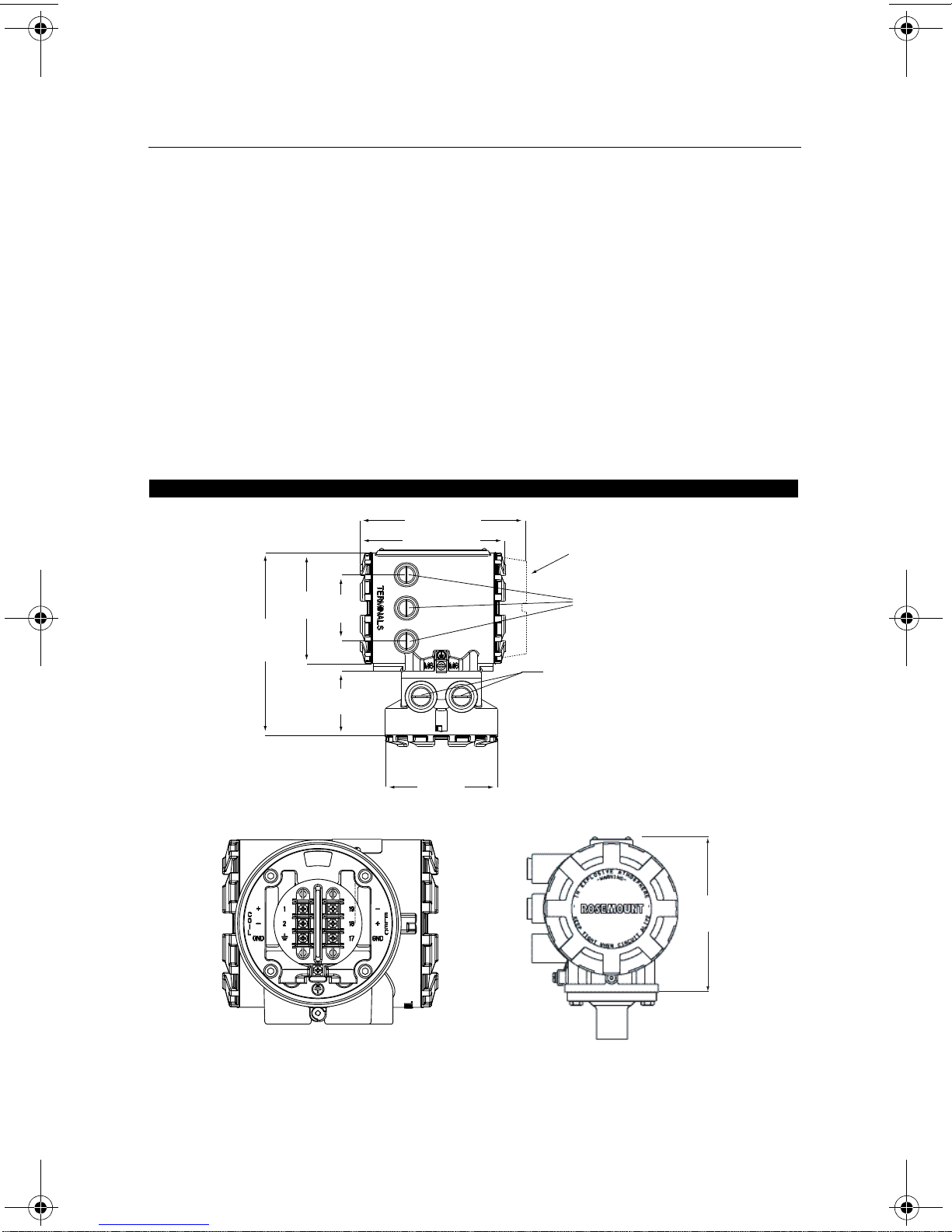
5.82
(148)
6.48 (165)
7.49 (190)
LOI Cover
4.97
(126)
8.81
(224)
3.00
(76)
3.07
(78)
4.97
(126)
1
/2”-14 NPT, CM20, or
PG 13.5 Electrical Conduit
Connections (3 places)
1
/2”-14 NPT, CM20, or PG 13.5
Sensor Conduit Connections (2
places)
00825-0100-4750, Rev BA
June 2009
Rosemount 8750WA
Before installing the Rosemount 8750WA Magnetic Flowmeter Transmitter, there are
several pre-installation steps that should be completed to make the installation process
easier:
• Identify the options and configurations that apply to your application
• Set the hardware switches if necessary
• Consider mechanical, electrical, and environmental requirements
Mechanical Considerations
The mounting site for the Rosemount 8750WA transmitter should provide enough room for
secure mounting, easy access to conduit ports, full opening of the transmitter covers, and
easy readability of the LOI screen (see Figure 1).
If the Rosemount 8750WA is mounted separately from the sensor, it is not subject to
limitations that might apply to the sensor.
Figure 1. Rosemount 8750WA Dimensional Drawing
3

Quick Installation Guide
STEP 1 CONTINUED...
00825-0100-4750, Rev BA
Rosemount 8750WA
June 2009
Environmental Considerations
To ensure maximum transmitter life, avoid excessive heat and vibration. Typical problem
areas:
• high-vibration lines with integrally mounted transmitters
• warm-climate installations in direct sunlight
• outdoor installations in cold climates.
Remote-mounted transmitters may be installed in the control room to protect the electronics
from the harsh environment and provide easy access for configuration or service.
Both remotely and integrally mounted Rosemount 8750WA transmitters require external
power so there must be access to a suitable power source.
Installation Procedures
Rosemount 8750WA installation includes both detailed mechanical and electrical installation
procedures.
Mount the Transmitter
At a remote site the transmitter may be mounted on a pipe up to two inches in diameter or
against a flat surface.
Pipe Mounting
To mount the transmitter on a pipe:
1. Attach the mounting bracket to the pipe using the mounting hardware.
2. Attach the Rosemount 8750WA transmitter to the mounting bracket using the mounting
screws.
Identify Options and Configurations
The standard application of the 8750WA includes a 4–20 mA output and control of the
sensor coils and electrodes. Other applications may require one or more of the following
configurations or options:
• Multidrop Communications
• Digital Output
• Digital Input
• Pulse Output
Additional options may apply . Be sure to identify those options and configurations that apply
to your situation, and keep a list of them nearby for consideration during the installation and
configuration procedures.
4
Quick Installation Guide
STEP 1 CONTINUED...
00825-0100-4750, Rev BA
June 2009
Rosemount 8750WA
Hardware Jumpers/Switches
The 8750WA electronics board is equipped with three or four user-selectable hardware
switches depending on the transmitter model ordered. These switches set the Failure Alarm
Mode, Internal/External Analog Power, Internal/External Pulse Power (8750WA32), and
Transmitter Security. The standard configuration for these switches when shipped from the
factory is as follows:
Failure Alarm Mode: HIGH
Internal/External Analog Power: INTERNAL
Internal/External Pulse Power: EXTERNAL (8750WA32 only)
Transmitter Security: OFF
Changing Hardware Switch Settings
In most cases, it is not necessary to change the setting of the hardware switches. If you
need to change the switch settings, complete the steps outlined in the manual.
Electrical Considerations
Before making any electrical connections to the Rosemount 8750WA, consider the local and
plant electrical standards and be sure to have the proper power supply, conduit, and other
accessories.
Rotate Transmitter Housing
The integral electronics housing can be rotated on the sensor in 90° increments by
loosening the four mounting bolts on the bottom of the housing, and reinstalling the bolts.
When reinstalling the housing, be sure the surface is clean and there is no gap between the
housing and the sensor.
5
Quick Installation Guide
STEP 2: HANDLING
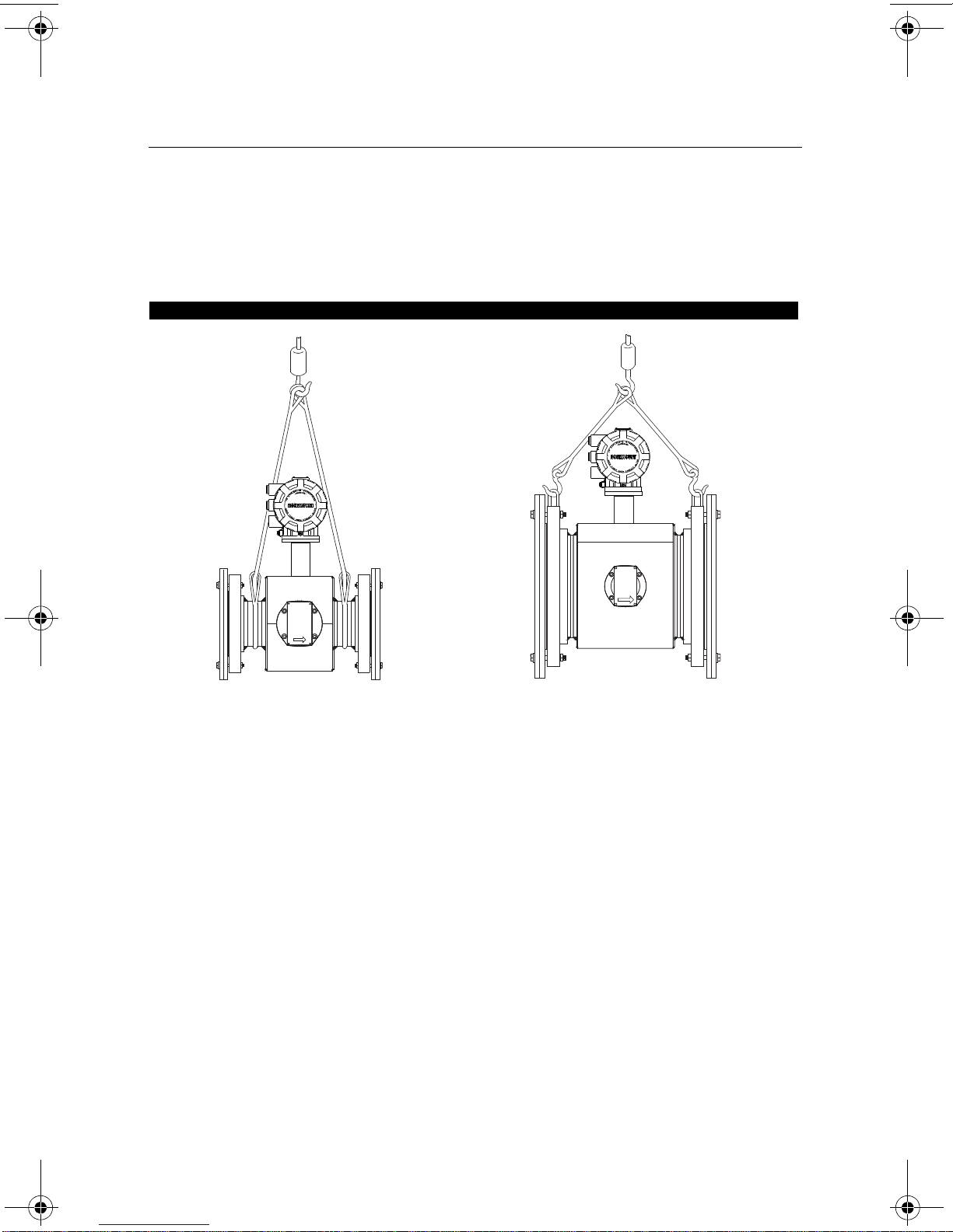
½- through 4-Inch Sensors
6-Inch and Larger Sensors
00825-0100-4750, Rev BA
Rosemount 8750WA
Handle all parts carefully to prevent damage. Whenever possible, transport the system to
the installation site in the original shipping containers. PTFE-lined sensors are shipped with
end covers that protect it from both mechanical damage and normal unrestrained distortion.
Remove the end covers just before installation.
Figure 2. Rosemount 8750WA Flanged Sensor Support for Handling
June 2009
6
Quick Installation Guide
STEP 3: MOUNTING
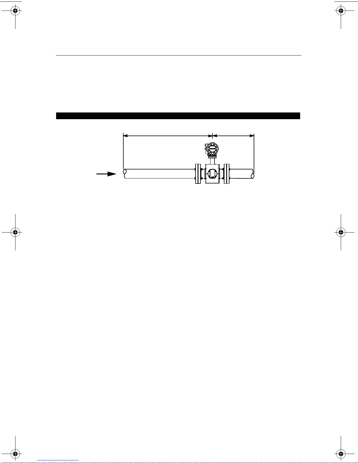
5 Pipe Diameters
2 Pipe Diameters
Flow
00825-0100-4750, Rev BA
June 2009
Rosemount 8750WA
Upstream/Downstream Piping
To ensure specification accuracy over widely varying process conditions, install the sensor a
minimum of five straight pipe diameters upstream and two pipe diameters downstream from
the electrode plane (see Figure 3).
Figure 3. Upstream and Downstream St raight Pipe Diameters
The 8750WA may be installed with as few as zero pipe diameters upstream. Consult the
factory for performance in applications with less than ideal straight runs. Sensors can be
installed with as few as zero diameters of straight run.
Flow Direction
The sensor should be mounted so the FORWARD end of the flow arrow, shown on the
sensor identification tag, points in the direction of flow through the sensor.
Sensor Orientation
The sensor should be installed in a position that ensures the sensor remains full during
operation. Vertical installation allows upward process fluid flow and keeps the
cross-sectional area full, regardless of flow rate. Horizontal installation should be restricted
to low piping sections that are normally full. In these cases, orient the electrode plane to
within 45 degrees of horizontal.
7
Rosemount 8750WA
STEP 3 CONTINUED...
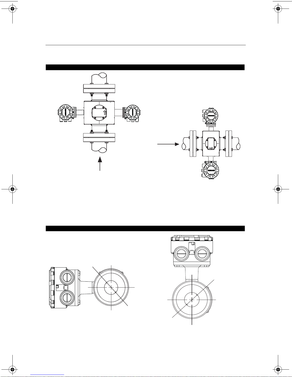
FLOW
FLOW
45° Electrode Plane
45° Electrode Plane
Figure 4. Sensor Orientation
Quick Installation Guide
00825-0100-4750, Rev BA
June 2009
The electrodes in the Rosemount 8750WA flanged sensor are properly orientated when the
two measurement electrodes are in the 3 and 9 o’clock positions, as shown on the right of
Figure 4.
The electrodes in the Rosemount 8750WA wafer sensor are properly orientated when the
top of the sensor is either vertical or horizontal, as shown in Figure 5. Avoid any mounting
orientation that positions the top of the sensor at 45° from the vertical or horizontal position.
Figure 5. Rosemount 8750WA Wafer Sensor Mounting Position
8
Quick Installation Guide
STEP 4: INSTALLATION
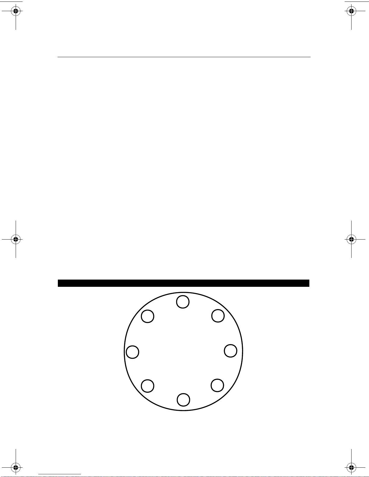
1
5
3
7
8
4
6
2
8-bolt
00825-0100-4750, Rev BA
June 2009
Rosemount 8750WA
Flanged Sensors
Gaskets
The sensor requires a gasket at each of its connections to adjacent devices or piping. The gasket
material selected must be compatible with the process fluid and operating conditions. Metallic or
spiral-wound gaskets can damage the liner. Gaskets are required on each side of a
grounding ring. All other applications (including sensors with lining protectors or a grounding
electrode) require only one gasket on each end connection.
Flange Bolts
Suggested torque values by sensor line size and liner type are listed in Table 1. Consult the
factory if the flange rating of the sensor is not listed. Tighten flange bolts on the upstream
side of the sensor in the incremental sequence shown in Figure 6 to 20% of the suggested
torque values. Repeat the process on the downstream side of the sensor. For sensors with
more or less flange bolts, tighten the bolts in a similar crosswise sequence. Repeat this
entire tightening sequence at 40%, 60%, 80%, and 100% of the suggested torque values or
until the leak between the process and sensor flanges stop.
If leakage has not stopped at the suggested torque values, the bolts can be tightened in
additional 10% increments until the joint stops leaking, or until the measured torque value
reaches the maximum torque value of the bolts. Practical consideration for the integrity of
the liner often leads the user to distinct torque values to stop leakage due to the unique
combinations of flanges, bolts, gaskets, and sensor liner material.
Check for leaks at the flanges after tightening the bolts. Failure to use the correct tightening
methods can result in severe damage. Sensors require a second tightening 24 hours after
the initial installation. Over time, sensor liner materials may deform under pressure.
Figure 6. Flange Bolt Torquing Sequence
9
Quick Installation Guide
STEP 4 CONTINUED...
00825-0100-4750, Rev BA
Rosemount 8750WA
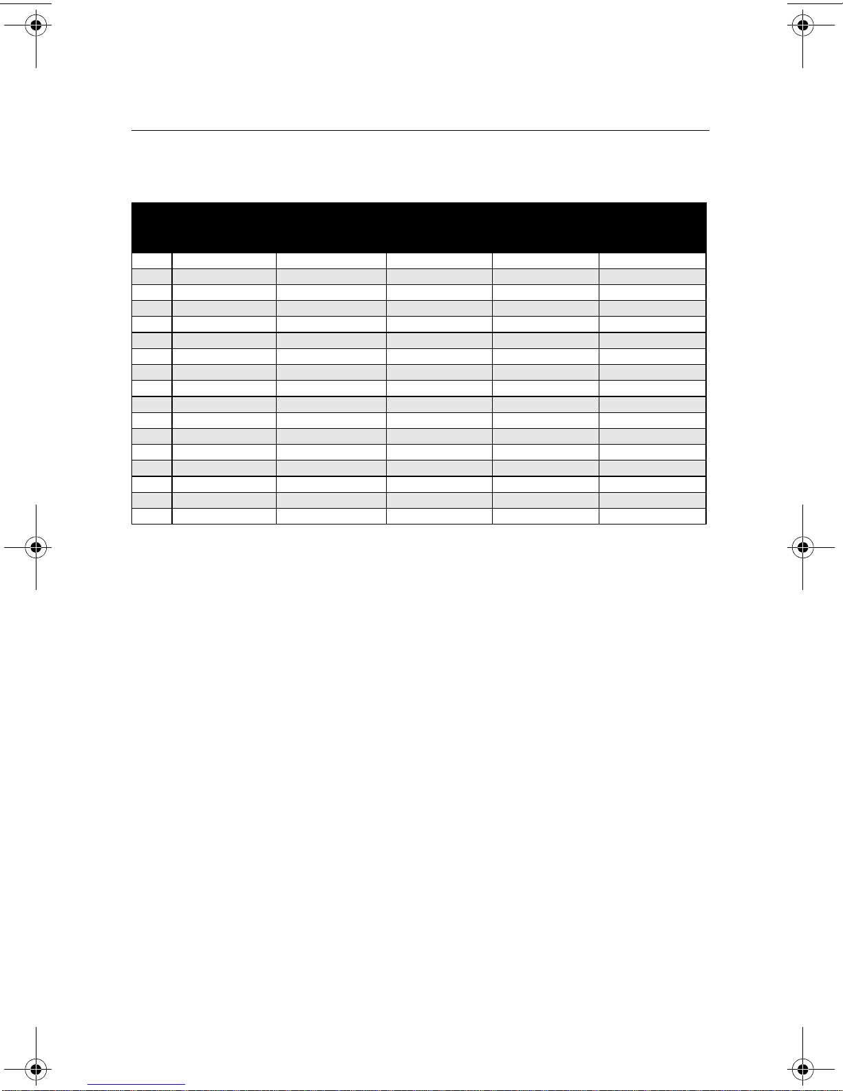
Table 1. Suggested Flange Bolt Torque Values for Rosemount 8750WA Flanged Sensors
PTFE Polyurethane/Neoprene liner
Size
Code
005 0.5 inch (15 mm) 8 8 - 010 1 inch (25 mm) 8 12 - 015 1.5 inch (40 mm) 13 25 7 18
020 2 inch (50 mm) 19 17 14 11
030 3 inch (80 mm) 34 35 23 23
040 4 inch (100 mm) 26 50 17 32
060 6 inch (150mm) 45 50 30 37
080 8 inch (200 mm) 60 82 42 55
100 10 inch (250 mm) 55 80 40 70
120 12 inch (300 mm) 65 125 55 105
140 14 inch (350 mm) 85 110 70 95
160 16 inch (400 mm) 85 160 65 140
180 18 inch (450 mm) 120 170 95 150
200 20 inch (500 mm) 110 175 90 150
240 24 inch (600 mm) 165 280 140 250
300 30 inch (750 mm) 195 415 165 375
360 36 inch (900 mm) 280 575 245 525
Line Size
Class 150
(pound-feet)
Class 300
(pound-feet)
Class 150
(pound-feet)
Class 300
(pound-feet)
June 2009
Wafer Sensors
Gaskets
The sensor requires a gasket at each of its connections to adjacent devices or piping. The gasket
material selected must be compatible with the process fluid and operating conditions. Metallic or
spiral-wound gaskets can damage the liner. Gaskets are required on each side of a
grounding ring.
Alignment and Bolting
1. On 1.5 - through 8-inch (40 through 200 mm) line sizes. Rosemount strongly
recommends ordering the centering rings to insure proper centering of the sensor
between the process flanges. Place the alignment rings over each end of the sensor.
The smaller line sizes, 0.5 and 1 in. (15 and 25 mm), do not require centering rings.
2. Insert studs for the bottom side of the sensor between the pipe flanges. Stud
specifications are listed in Table 2.
NOTE
Using carbon steel bolts on smaller line sizes, 0.5 and 1 in. (15 and 25 mm), rather than the
required stainless steel bolts, will degrade performance.
10
Quick Installation Guide
STEP 4 CONTINUED...
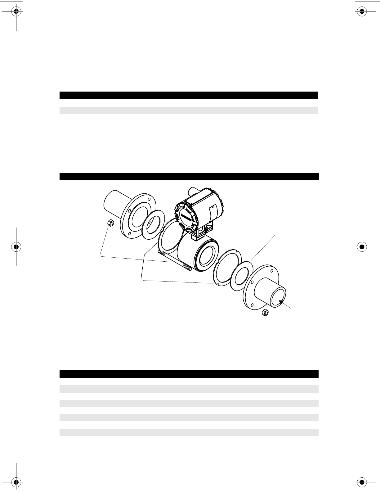
Alignment
Rings
Installation,
Studs Nuts
and Washers
Customer-supplied
Gasket
FLOW
00825-0100-4750, Rev BA
June 2009
Table 2. Stud Specifications
Nominal Sensor Size Stud Specifications
0.5 – 1 inch (15 – 25 mm) 316 SST ASTM A193, Grade B8M Class 1 threaded mounted studs
1.5 – 8 inch (40 – 200 mm) CS, ASTM A193, Grade B7, threaded mounting studs
3. Place the sensor between the flanges. Make sure that the alignment rings are properly
placed in the studs. The studs should be aligned with the markings on the rings that
correspond to the flange you are using.
4. Insert the remaining studs, washers, and nuts.
5. Tighten to the torque specifications shown in Table 3 on page 11. Do not overtighten the
bolts or the liner may be damaged.
Figure 7. Gasket Placement with Centering Rings
Rosemount 8750WA
Flange Bolts
Tighten flange bolts in crosswise sequence. Always check for leaks at the flanges after
tightening the flange bolts. All sensors require a second torquing 24 hours after initial flange
bolt tightening.
Table 3. Rosemount 8750WA Wafer Sensor Torque Specifications
Size Code Line Size Pound-feet Newton-meter
005 0.5 inch (15 mm) 5 7
010 1 inch (25 mm) 10 14
015 1.5 inch (40 mm) 15 20
020 2 inch (50 mm) 25 34
030 3 inch (80 mm) 40 54
040 4 inch (100 mm) 30 41
060 6 inch (150 mm) 50 68
080 8 inch (200 mm) 70 95
11
Quick Installation Guide
STEP 5: GROUNDING
00825-0100-4750, Rev BA
Rosemount 8750WA
Use Table 4 to determine which process grounding option to follow for proper installation.
The sensor case should be earth grounded in accordance with national and local electrical
codes. Failure to do so may impair the protection provided by the equipment.
Table 4. Process Grounding Installation
Process Grounding Options
Grounding
Type of Pipe
Conductive
Unlined Pipe
Conductive Lined
Pipe
Non-Conductive
Pipe
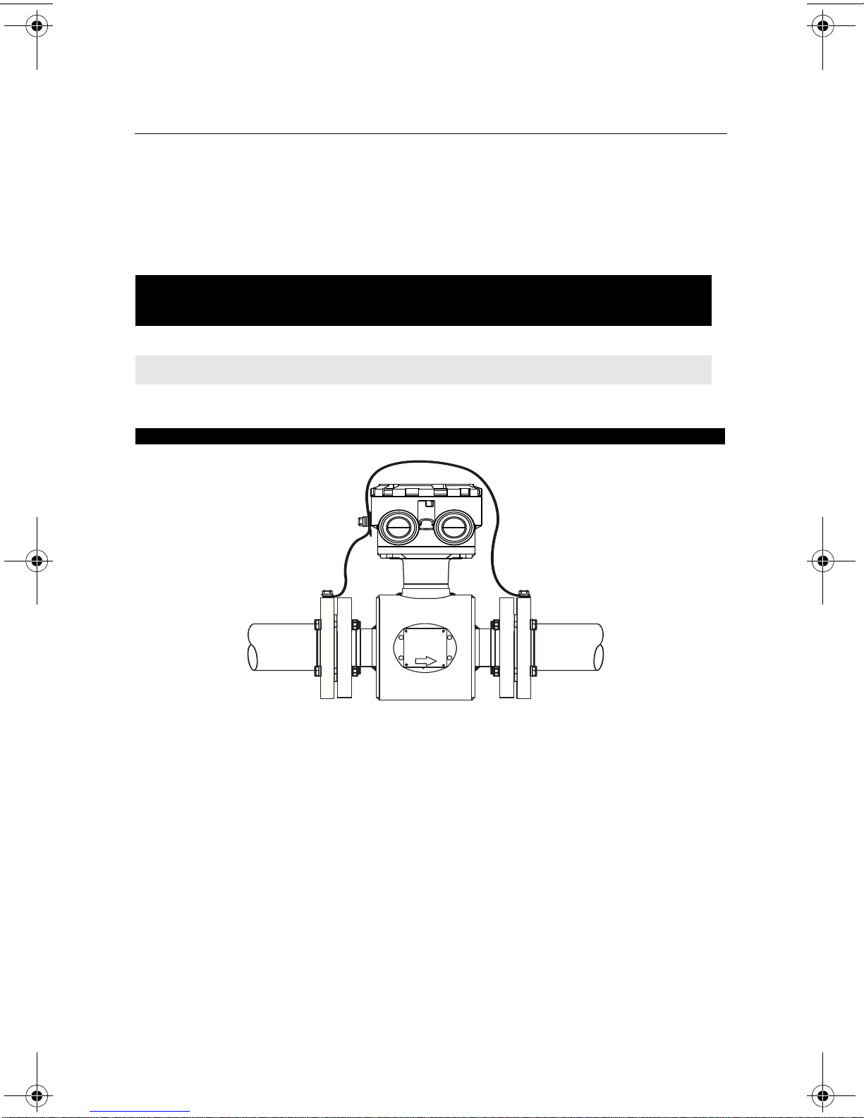
Figure 8. Grounding Straps or Grounding Electrode in Lined Pipe
Straps
See Figure 8 Not Required Not Required See Figure 9
Insufficient
Grounding
Insufficient
Grounding
Grounding
Rings
See Figure 9 See Figure 8 See Figure 9
See Figure 10 See Figure 11 See Figure 10
Grounding
Electrode
June 2009
Lining
Protectors
12
 Loading...