

Page 1
Quick Start Guide
00825-0300-4750, Rev CA
March 2016
Rosemount™ 8750W
Magnetic Flowmeter System
for Utility, Water, and Wastewater Applications
Page 2

Quick Start Guide
March 2016
NOTICE
This document provides basic installation guidelines for the Rosemount 8750W Magnetic Flowmeter
Platform. For comprehensive instructions for detailed configuration, diagnostics, maintenance, service,
installation, or troubleshooting refer to the Rosemount 8750W Reference Manual (document number
00809-0300-4750). The manual and Quick Start Guide are also available electronically on
Emerso nProcess.co m/Rosemount
Failure to follow these installation guidelines could result in death or serious injury.
Installation and servicing instructions are for use by qualified personnel only. Do not perform any servicing
other than that contained in the operating instructions, unless qualified.
Verify the installation is done safely and is consistent with the operating environment.
Ensure the device certification and installation techniques are suitable for the ins tallation environment.
Explosion hazard. Do not disconnect equipment when a flammable or combustible atmosphere is present.
To prevent ignition of flammable or combustible atmospheres, disconnect power before servicing circuits.
Do not connect a Rosemount 8750W Transmitter to a non-Rosemount sensor that is located in an explosive
atmosphere.
Follow national, local, and plant standards to properly earth ground the transmitter and sensor. The earth
ground must be separate from the process reference ground.
Rosemount Magnetic Flowmeters ordered with non-standard paint options or non-metallic labels may be
subject to electrostatic discharge. To avoid electrostatic charge build-up, do not rub the flowmeter with a
dry cloth or clean with solvents.
.
NOTICE
The sensor liner is vulnerable to handling damage. Never place anything through the sensor for the
purpose of lifting or gaining leverage. Liner damage may render the sensor inoperable.
Metallic or spiral-wound gaskets should not be used as they will damage the liner face of the sensor. If
frequent removal is anticipated, take precautions to protect the liner ends. Short spool pieces attached to
the sensor ends are often used for protection.
Correct flange bolt tightening is crucial for proper sensor operation and life. All bolts must be tightened in
the proper sequence to the specified torque specifications. Failure to observe these instructions could
result in severe damage to the sensor lining and possible sensor replacement.
In cases where high voltage/high current are present near the meter installation, ensure proper protection
methods are followed to prevent stray voltage/current from passing through the meter. Failure to
adequately protect the meter could result in damage to the transmitter and lead to meter failure.
Completely remove all electrical connections from both sensor and transmitter prior to welding on the
pipe. For maximum protection of the sensor, consider removing it from the pipeline.
Contents
Transmitter installation . . . . . . . . . . . . . . . . . 3
Handling and lifting . . . . . . . . . . . . . . . . . . . . 8
Mounting . . . . . . . . . . . . . . . . . . . . . . . . . . . . . 9
Sensor installation . . . . . . . . . . . . . . . . . . . . . 11
Process reference connection . . . . . . . . . . . 16
2
Wiring the transmitter . . . . . . . . . . . . . . . . . . . . . . 18
Basic configuration . . . . . . . . . . . . . . . . . . . . . . . . . 31
Product Certifications . . . . . . . . . . . . . . . . . . . . . . 36
Installation and wiring drawings . . . . . . . . . . . . . . 48
Page 3

March 2016
Quick Start Guide
1.0 Transmitter installation
Installation of the Rosemount Magnetic Flowmeter Transmitter includes both
detailed mechanical and electrical installation procedures.
Before installing the Rosemount 8750W, there are several pre-installation steps
that should be completed to make the installation process easier:
Identify the options and configurations that apply to your application.
Set the hardware switches if necessary.
Consider mechanical, electrical, and environmental requirements.
1.1 Identify options and configurations
The typical installation of the Rosemount 8750W includes a device power
connection, a 4
connections. Other applications may require one or more of the following
configurations or options:
Pulse output
Discrete input/discrete output
HART
Hardware switches
The Rosemount 8750W electronics stack is equipped with user-selectable
hardware switches. These switches set the Alarm mode, Internal/external analog
power, Internal/external pulse power
configuration for these switches when shipped from the factory are as follows:
Table 1. Standard Switch Configuration
–20mA output connection, and sensor coil and electrode
®
Multidrop Configuration
(1)
, and Transmitter security. The standard
Setting Standard switch configuration
Alarm mode High
Internal/external analog power Internal
Internal/external pulse power
Transmitter security Off
(1)
External
In most cases, it will not be necessary to change the setting of the hardware
switches. If the switch settings need to be changed, follow the steps outlined in
the “Changing hardware switch settings” section of the Rosemount 8750W
Reference Manual.
NOTICE
To prevent switch damage, use a non-metallic tool to move switch positions.
Be sure to identify any additional options and configurations that apply to the
installation. Keep a list of these options for consideration during the installation
and configuration procedures.
1. Rosemount 8750W Field Mount Transmitter only.
3
Page 4

Quick Start Guide
1.2 Mechanical considerations
The mounting site for the Rosemount 8750W should provide enough room for
secure mounting, easy access to conduit entries, full opening of the transmitter
covers, and easy readability of the LOI screen if equipped.
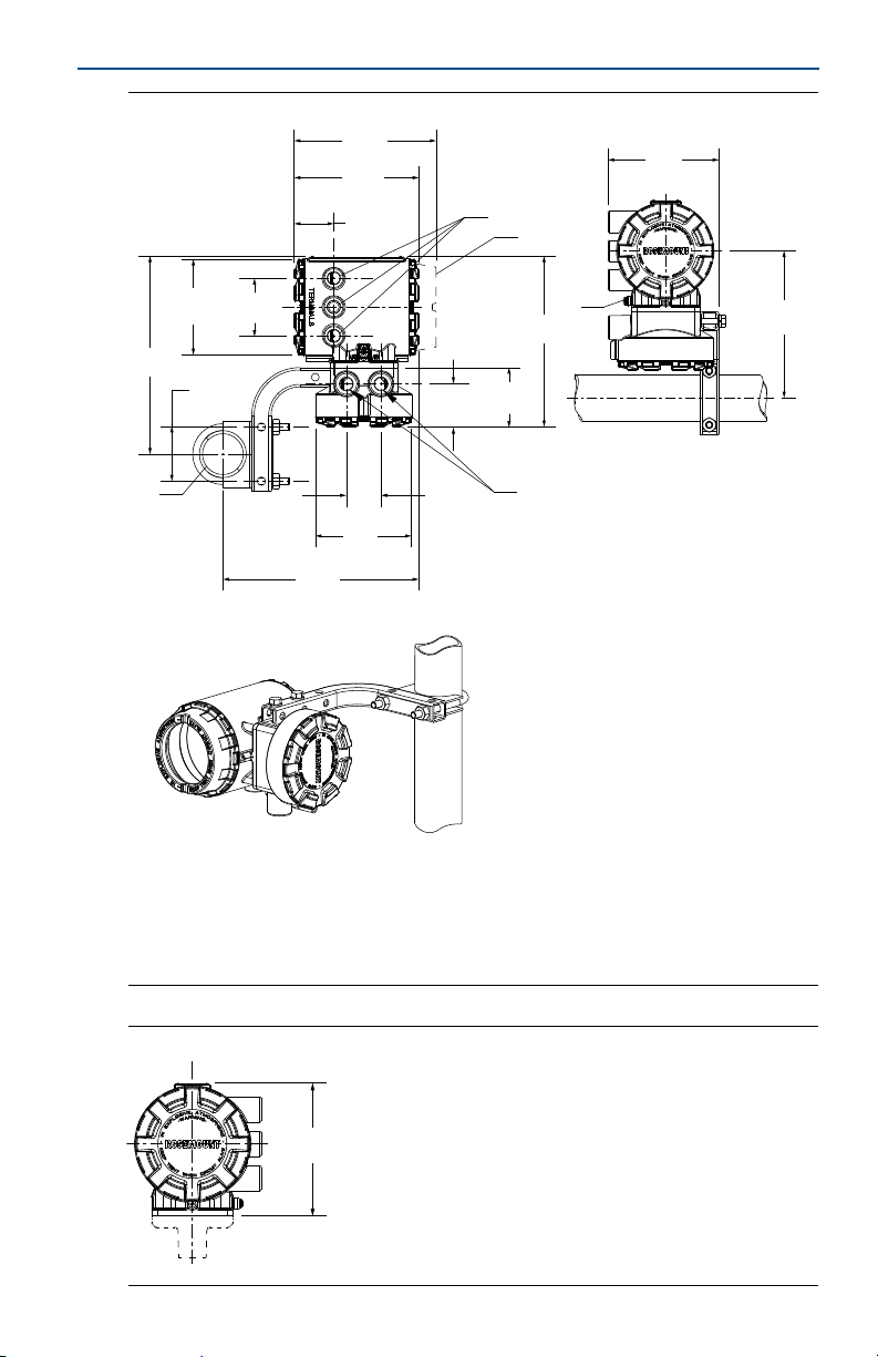
For remote field mount transmitter installations, a mounting bracket is provided
for use on a 2-in. pipe or a flat surface (see Figure 1).
NOTICE
If the transmitter is mounted separately from the sensor, it may not be subject to limitations that
might apply to the sensor.
Rotate integral mount transmitter housing
The transmitter housing can be rotated on the sensor in 90° increments by
removing the four mounting screws on the bottom of the housing. Do not rotate
the housing more than 180° in any one direction. Prior to tightening, be sure the
mating surfaces are clean, the O-ring is seated in the groove, and there is no gap
between the housing and the sensor.
March 2016
4
Page 5
March 2016
7.49
(189,8)
6.48
(164,6)
1.94
(49,3)
A
B
C
A
D
5.77
(146,4)
7.64
(194,0)
8.86
(225,1)
3.07
(78,0)
2.22
(56,4)
3.00
(76,2)
5.00
(127,0)
10.29
(261,3)
2.81
(71,4)
5.00
(127,0)
1.80
(45,7)
10.18
(258,6)
5.82
(147,8)
Figure 1. Rosemount 8750W Field Mount Transmitter
Quick Start Guide
A. 1/2-in.–14 NPT conduit entry
B. LOI cover
C. 2-in. pipe bracket
D. Ground lug
Dimensions are in inches (millimeters).
Figure 2. Rosemount 8750W Integral Field Mount Transmitter
5
Page 6
Quick Start Guide
A
B
March 2016
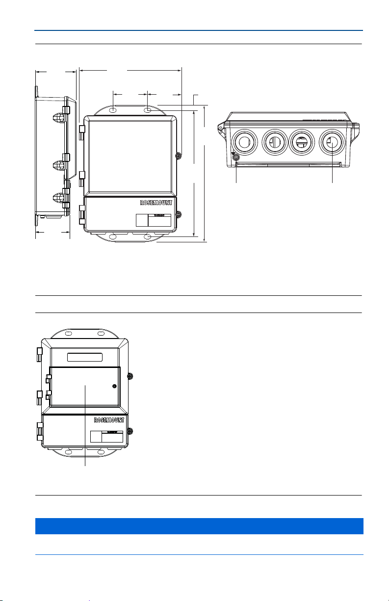
Figure 3. Rosemount 8750W Wall Mount Transmitter with Standard Cover
4.31
(109)
2.96
(75)
A. Ground lug
1
B.
/2-in.–14 NPT or M20 conduit entry
Dimensions in inches (millimeters).
9.01
(229)
2.81
(71)
3.11
(79)
0.44
12.02
(305)
11.15
(283)
Figure 4. Rosemount 8750W Wall Mount Transmitter with LOI Cover
A
A. LOI keypad cover
NOTICE
Default conduit entries are 1/2-in. NPT. If an alternate thread connection is required, thread adapters must be
used.
6
Page 7
March 2016
Quick Start Guide
1.3 Electrical considerations
Before making any electrical connections to the Rosemount 8750W, consider
national, local and plant electrical installation requirements. Be sure to have the
proper power supply, conduit, and other accessories necessary to comply with
these standards.
Both remotely and integrally mounted transmitters require external power so
there must be access to a suitable power source.
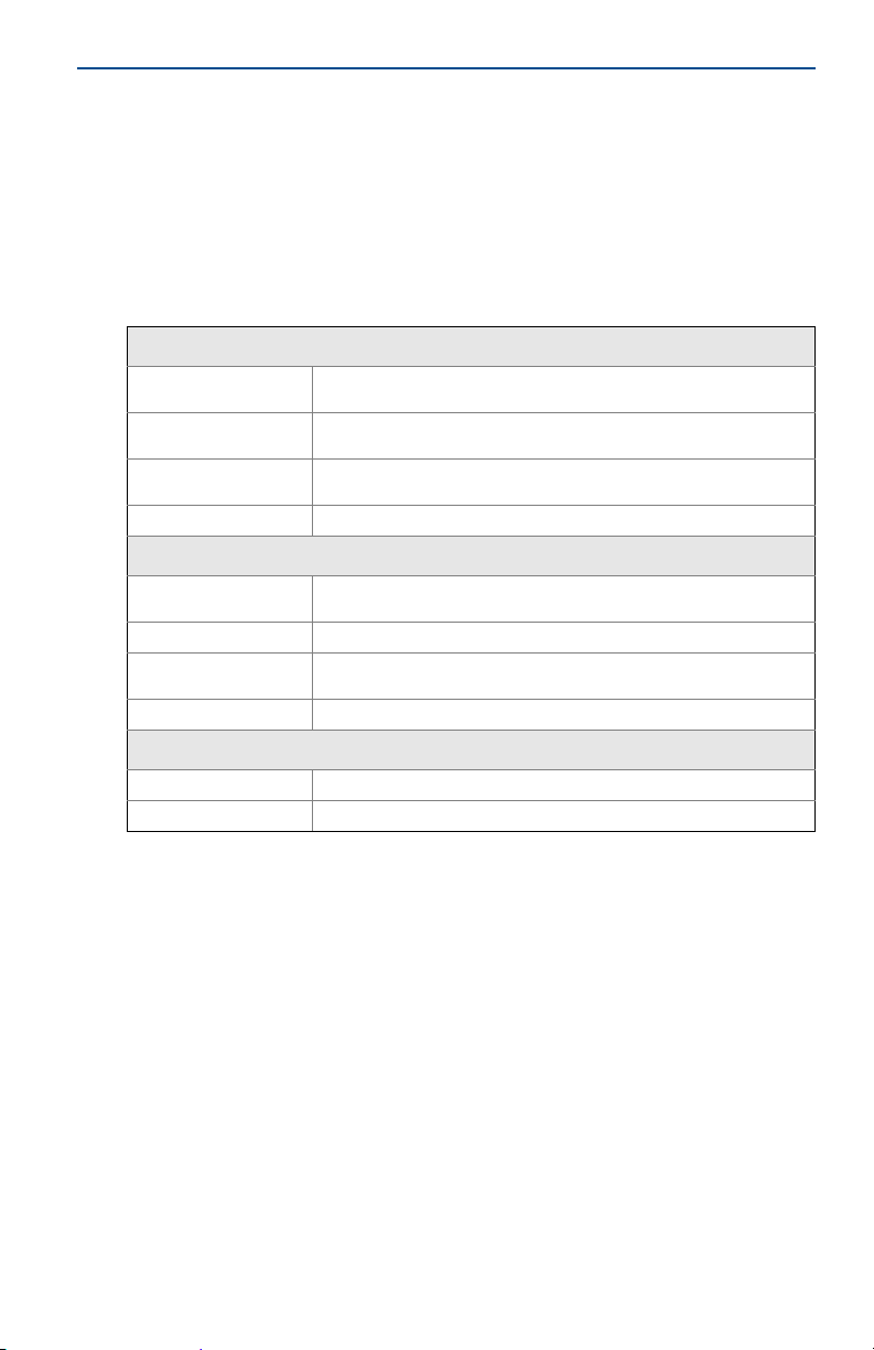
Table 2. Electrical Data
Field mount transmitter
Power input
Pulsed circuit
4-20mA output circuit
Coil excitation output 500mA, 40V max, 9W max
Wall mount transmitter
Power input
Pulsed circuit Externally powered (Passive): 5–24VDC, up to 2W
4-20mA output circuit
Coil excitation output 500mA, 40V max, 9W max
(1)
Sensor
Coil excitation input 500mA, 40V max, 20W max
Electrode circuit 5V, 200uA, 1mW
90–250VAC, 0.45A, 40VA
12–42VDC, 1.2A, 15W
Internally powered (Active): Outputs up to 12VDC, 12.1mA, 73mW
Externally powered (Passive): Input up to 28VDC, 100mA, 1W
Internally Powered (Active): Outputs up to 25mA, 24VDC, 600mW
Externally Powered (Passive): Input up to 25mA, 30VDC, 750mW
90–250VAC, 0.28A, 40VA
12–42VDC, 1A, 15W
Internally powered (Active): Outputs up to 25mA, 30VDC
Externally powered (Passive): Input up to 25mA, 10–30VDC
1. Provided by the transmitter.
1.4 Environmental considerations
To ensure maximum transmitter life, avoid extreme temperatures and excessive
vibration. Typical problem areas:
high-vibration lines with integrally mounted transmitters
tropical/desert installations in direct sunlight
outdoor installations in arctic climates
Remote-mounted transmitters may be installed in the control room to protect
the electronics from the harsh environment and to provide easy access for
configuration or service.
7
Page 8
Quick Start Guide
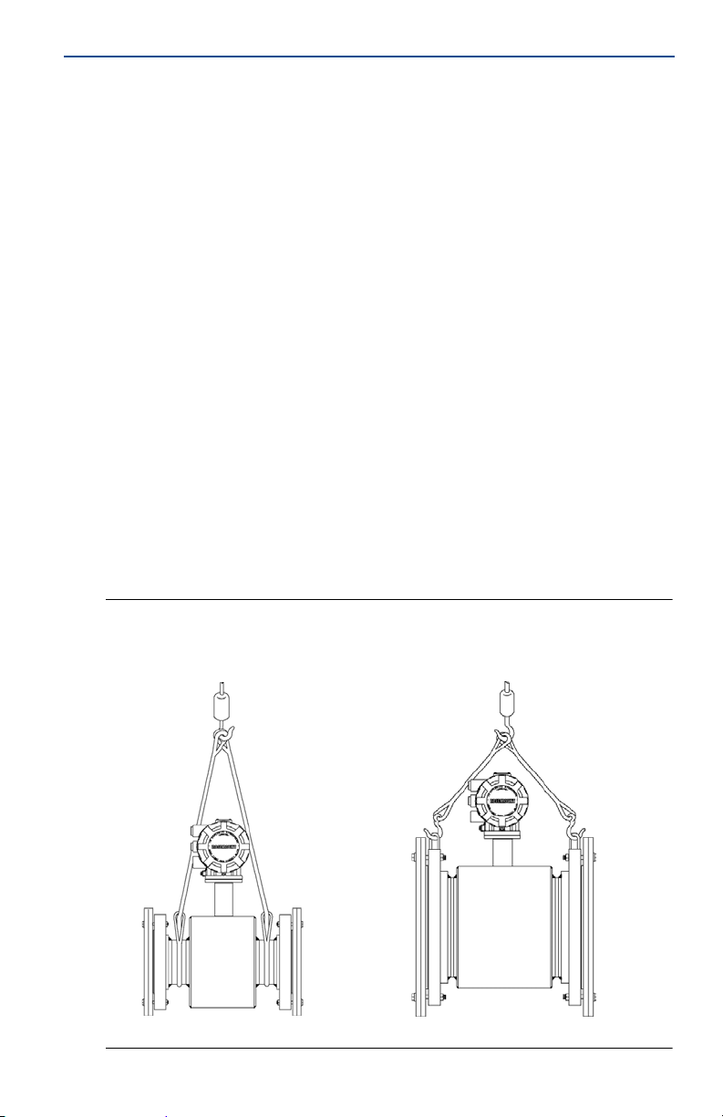
2.0 Handling and lifting
Handle all parts carefully to prevent damage. Whenever possible, transport
the system to the installation site in the original shipping container.
PTFE-lined sensors are shipped with end covers that protect it from both
mechanical damage and normal unrestrained distortion. Remove the end
covers just before installation.
Keep the shipping plugs in the conduit connections until you are ready to
connect and seal them.
The sensor should be supported by the pipeline. Pipe supports are
recommended on both the inlet and outlet sides of the sensor pipeline. There
should be no additional support attached to the sensor.
Additional safety recommendations for mechanical handling:
- Use proper PPE (Personal Protection Equipment should include safety
glasses and steel toed shoes).
- Do not drop the device from any height.
Do not lift the meter by holding the electronics housing or junction box.The
sensor liner is vulnerable to handling damage. Never place anything through
the sensor for the purpose of lifting or gaining leverage. Liner damage can
render the sensor useless.
If provided, use the lifting lugs on each flange to handle the Magnetic
Flowmeter when it is transported and lowered into place at the installation
site. If lifting lugs are not provided, the Magnetic Flowmeter must be
supported with a lifting sling on each side of the housing.
Flanged sensors 3-in. through 48-in. come with lifting lugs.
Wafer sensors do not come with lifting lugs.
March 2016
Figure 5. Support for Handling and Lifting
Without lifting lugs
8
With lifting lugs
Page 9
March 2016
Quick Start Guide
3.0 Mounting
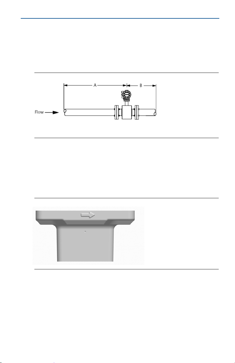
3.1 Upstream/downstream piping
To ensure specified accuracy over widely varying process conditions, install the
sensor with a minimum of five straight pipe diameters upstream and two pipe
diameters downstream from the electrode plane (see Figure 6).
Figure 6. Upstream and Downstream Straight Pipe Diameters
A. Five pipe diameters
B. Two pipe diameters
Installations with reduced upstream and downstream straight runs are possible.
In reduced straight run installations, the meter may not meet absolute accuracy
specifications. Reported flow rates will still be highly repeatable.
3.2 Flow direction
The sensor should be mounted so the arrow points in the direction of flow.
See Figure 7.
Figure 7. Flow Direction Arrow
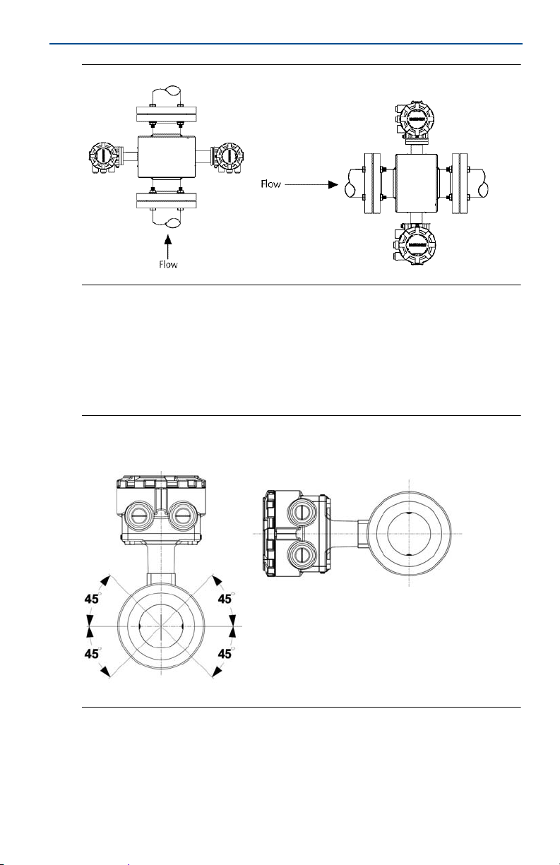
3.3 Sensor location
The sensor should be installed in a location that ensures it remains full during
operation. Vertical installation with upward process fluid flow keeps the
cross-sectional area full, regardless of flow rate. Horizontal installation should be
restricted to low piping sections that are normally full.
9
Page 10
Quick Start Guide
Figure 8. Sensor Orientation
3.4 Electrode orientation
The electrodes in the sensor are properly oriented when the two measurement
electrodes are in the 3 and 9 o’clock positions or within 45° from the horizontal,
as shown on the left of Figure 9. Avoid any mounting orientation that positions
the top of the sensor at 90° from the vertical position as shown on the right of
Figure 9.
Figure 9. Mounting Position
Correct
Incorrect
March 2016
10
Page 11
March 2016
Quick Start Guide
4.0 Sensor installation
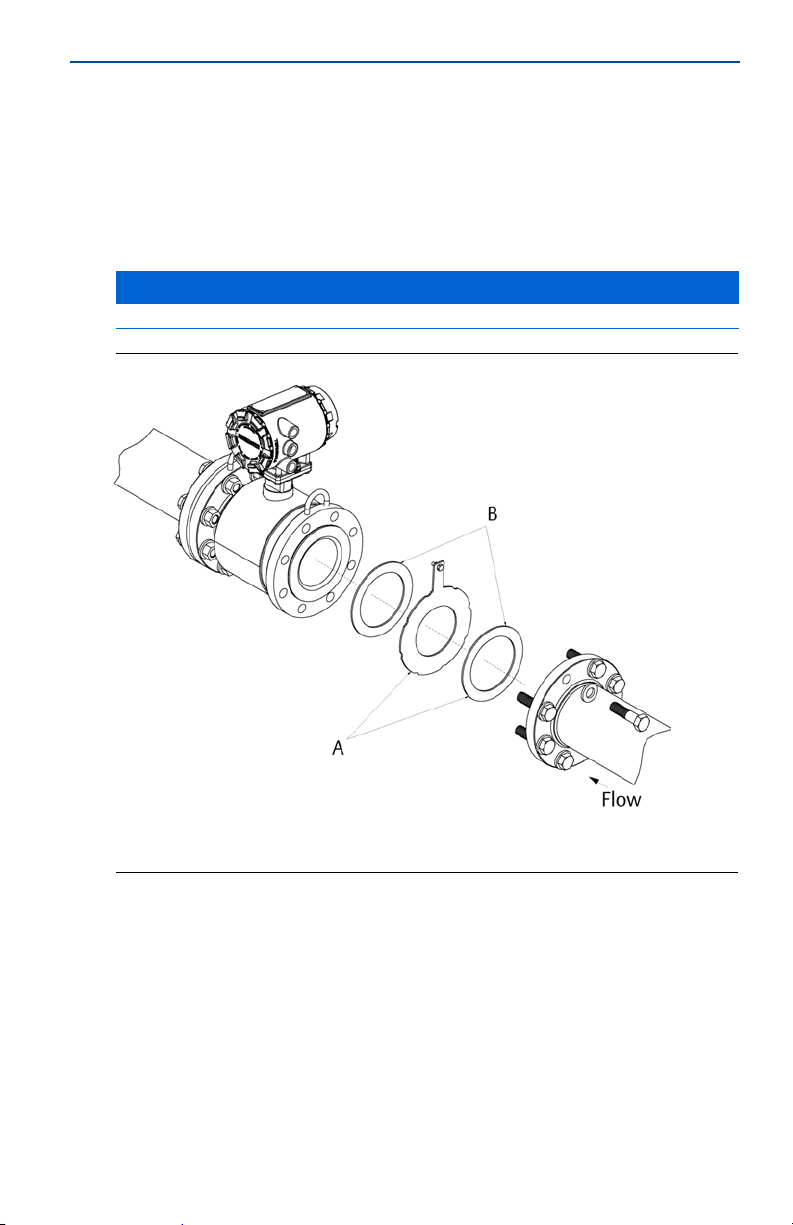
4.1 Gaskets
The sensor requires a gasket at each process connection. The gasket material must be
compatible with the process fluid and operating conditions. G askets are required on
each side of a grounding ring (see Figure 10). All other applications (including
sensors or a grounding electrode) require only one gasket on each process
connection.
NOTICE
Metallic or spiral-wound gaskets should not be used as they will damage the liner face of the sensor.
Figure 10. Flanged Gasket Placement
A. Grounding ring and gasket (optional)
B. Customer-supplied gasket
11
Page 12

Quick Start Guide
March 2016
4.2 Flange bolts
Note
Do not bolt one side at a time. Tighten both sides simultaneously. Example:
1. Snug upstream.
2. Snug downstream.
3. Tighten upstream.
4. Tighten downstream.
Do not snug and tighten the upstream side and then snug and tighten the downstream side.
Failure to alternate between the upstream and downstream flanges when tightening bolts may
result in liner damage.
Suggested torque values by sensor line size and liner type are listed in Table 4 for
ASME B16.5 flanges, Table 5 for EN flanges, and Table 6 and Table 7 for AWWA
and EN flanges for line sizes 30-in. (750 mm) to 48-in. (1300 mm). Consult your
local Emerson
sensor is not listed. Tighten flange bolts on the upstream side of the sensor in the
incremental sequence shown in Figure 11 to 20 percent of the suggested torque
values. Repeat the process on the downstream side of the sensor. For sensors
with more or less flange bolts, tighten the bolts in a similar crosswise sequence.
Repeat this entire tightening sequence at 40, 60, 80, and 100% of the suggested
torque values.
If leakage occurs at the suggested torque values, the bolts can be tightened in
additional 10% increments until the joint stops leaking, or until the measured
torque value reaches the maximum torque value of the bolts. Practical
consideration for the integrity of the liner often leads the user to distinct torque
values to stop leakage due to the unique combinations of flanges, bolts, gaskets,
and sensor liner material.
Check for leaks at the flanges after tightening the bolts. Failure to use the correct
tightening methods can result in severe damage. While under pressure, sensor
materials may deform over time and require a second tightening 24 hours after
the initial installation.
™
Process Management representative if the flange rating of the
Figure 11. Flange Bolt Torquing Sequence
Prior to installation, identify the lining material of the flow sensor to ensure the
suggested torque values are applied.
12
Page 13

March 2016
Table 3. Lining Material
Quick Start Guide
Fluoropolymer liners
T - PTFE
Resilient liners
P - Polyurethane
N - Neoprene
Table 4. Flange Bolt Torque and Load Specifications for 8750W (ASME)
Size
code
005 0.5-in. (15 mm) 8 8 N/A N/A
010 1-in. (25 mm) 8 12 N/A N/A
015 1.5-in. (40 mm) 13 25 7 18
020 2-in. (50 mm) 19 17 14 11
025 2.5-in. (65 mm) 22 24 17 16
030 3-in. (80 mm) 34 35 23 23
040 4-in. (100 mm) 26 50 17 32
050 5-in. (125 mm) 36 60 25 35
060 6-in. (150 mm) 45 50 30 37
080 8-in. (200 mm) 60 82 42 55
100 10-in. (250 mm) 55 80 40 70
120 12-in. (300 mm) 65 125 55 105
140 14-in. (350 mm) 85 110 70 95
160 16-in. (400 mm) 85 160 65 140
180 18-in. (450 mm) 120 170 95 150
200 20-in. (500 mm) 110 175 90 150
240 24-in. (600 mm) 165 280 140 250
Line size
Fluoropolymer liners Resilient liners
Class 150
(pound-feet)
Class 300
(pound-feet)
Class 150
(pound-feet)
Class 300
(pound-feet)
13
Page 14

Quick Start Guide
Table 5. Flange Bolt Torque and Load Specifications for 8750W (EN 1092-1)
March 2016
Size
code
005 0.5-in. (15 mm) N/A N/A N/A 10
010 1-in. (25 mm) N/A N/A N/A 20
015 1.5-in. (40 mm) N/A N/A N/A 50
020 2-in. (50 mm) N/A N/A N/A 60
025 2.5-in. (65 mm) N/A N/A N/A 50
030 3-in. (80 mm) N/A N/A N/A 50
040 4-in. (100 mm) N/A 50 N/A 70
050 5-in. (125 mm) N/A 70 N/A 100
060 6-in. (150mm) N/A 90 N/A 130
080 8-in. (200 mm) 130 90 130 170
100 10-in. (250 mm) 100 130 190 250
120 12-in. (300 mm) 120 170 190 270
140 14-in. (350 mm) 160 220 320 410
160 16-in. (400 mm) 220 280 410 610
180 18-in. (450 mm) 190 340 330 420
200 20-in. (500 mm) 230 380 440 520
240 24-in. (600 mm) 290 570 590 850
Size
code
010 1-in. (25 mm) N/A N/A N/A 20
015 1.5-in. (40 mm) N/A N/A N/A 30
020 2-in. (50 mm) N/A N/A N/A 40
025 2.5-in. (65 mm) N/A N/A N/A 35
030 3-in. (80 mm) N/A N/A N/A 30
040 4-in. (100 mm) N/A 40 N/A 50
050 5-in. (125 mm) N/A 50 N/A 70
060 6-in. (150 mm) N/A 60 N/A 90
080 8-in. (200 mm) 90 60 90 110
100 10-in. (250 mm) 70 80 130 170
120 12-in. (300 mm) 80 110 130 180
140 14-in. (350 mm) 110 150 210 280
160 16-in. (400 mm) 150 190 280 410
180 18-in. (450 mm) 130 230 220 280
200 20-in. (500 mm) 150 260 300 350
240 24-in. (600 mm) 200 380 390 560
Line size
Line size
PN10
(Newton-meter)
PN 10
(Newton-meter)
Fluoropolymer liners
PN 16
(Newton-meter)
Resilient liners
PN 16
(Newton-meter)
PN 25
(Newton-meter)
PN 25
(Newton-meter)
PN 40
(Newton-meter)
PN 40
(Newton-meter)
14
Page 15
March 2016
Quick Start Guide
Table 6. Flange Bolt Torque and Load Specifications for Rosemount 8750W
Larger Line Sizes (AWWA C207)
Size
code
300 30-in. (750 mm) 195 195 195
360 36-in. (900 mm) 280 280 280
300 30-in. (750 mm) 165 165 165
360 36-in. (900 mm) 245 245 245
400 40-in. (1000 mm) 757 757 N/ A
420 42-in. (1050 mm) 839 839 N/ A
480 48-in. (1200 mm) 872 872 N/ A
Line size
Class D
(pound-feet)
Fluoropolymer liners
Class E
(pound-feet)
Resilient liners
Class F
(pound-feet)
Table 7. Flange Bolt Torque and Load Specifications for Rosemount 8750W
Larger Line Sizes (EN 1092-1)
Size
code
360 36-in. (900 mm) N/A 264 264
360 36-in. (900 mm) N/A 264 264
400 40-in. (1000 mm) 208 413 478
480 48-in. (1200 mm) 375 622 N/ A
Line size
PN6
(Newton-meter)
Fluoropolymer liners
PN10
(Newton-meter)
Resilient liners
PN16
(Newton-meter)
15
Page 16
Quick Start Guide
March 2016
5.0 Process reference connection
Figure 12 through Figure 15 illustrate process reference connections only. Earth
safety ground is also required as part of the installation but is not shown in the
figures. Follow national, local, and plant electrical codes for safety ground.
Use Table 8 to determine which process reference option to follow for proper
installation.
Table 8. Process reference installation
Process reference options
Type of pipe Grounding straps Grounding rings
Conductive unlined
pipe
Conductive lined pipe Insufficient grounding See Figure 13 See Figure 12
Non-conductive pipe Insufficient grounding See Figure 14 Not recommended
1. Grounding ring and reference electrode are not required for process reference. Grounding straps
per Figure 12 are sufficient.
See Figure 12 See Figure 13
Note
For line sizes 10-in. and larger, the ground strap may come attached to the sensor body near the
flange. See Figure 16.
(1)
Reference electrode
See Figure 15
(1)
Figure 12. Grounding Straps in Conductive Unlined Pipe or Reference
Electrode in Lined Pipe
16
Page 17

March 2016
Figure 13. Grounding with Grounding Rings in Conductive Pipe
A. Grounding rings
Figure 14. Grounding with Grounding Rings in Non-conductive Pipe
Quick Start Guide
A. Grounding rings
Figure 15. Grounding with Reference Electrode in Conductive Unlined Pipe
17
Page 18

Quick Start Guide
Figure 16. Grounding for Line Sizes 10-in. and Larger
6.0 Wiring the transmitter
This wiring section covers the wiring between the transmitter and sensor, the
4–20mA output, and supplying power to the transmitter. Follow the conduit
information, cable requirements, and disconnect requirements in the sections
below.
For sensor wiring diagrams, see Electrical Drawing 8750W-1504.
See Installation Drawing 8750W-1052.
March 2016
6.1 Conduit entries and connections
The standard conduit entries for the transmitter and sensor are 1/2-in. NPT.
Conduit connections should be made in accordance with national, local, and
plant electrical codes. Unused conduit entries should be sealed with the
appropriate certified plugs. The flow sensor is rated IP68. For sensor installations
requiring IP68 protection, the cable glands, conduit, and conduit plugs must be
rated for IP68. The plastic shipping plugs do not provide ingress protection.
6.2 Conduit requirements
Bundled cables from other equipment in a single conduit are likely to create
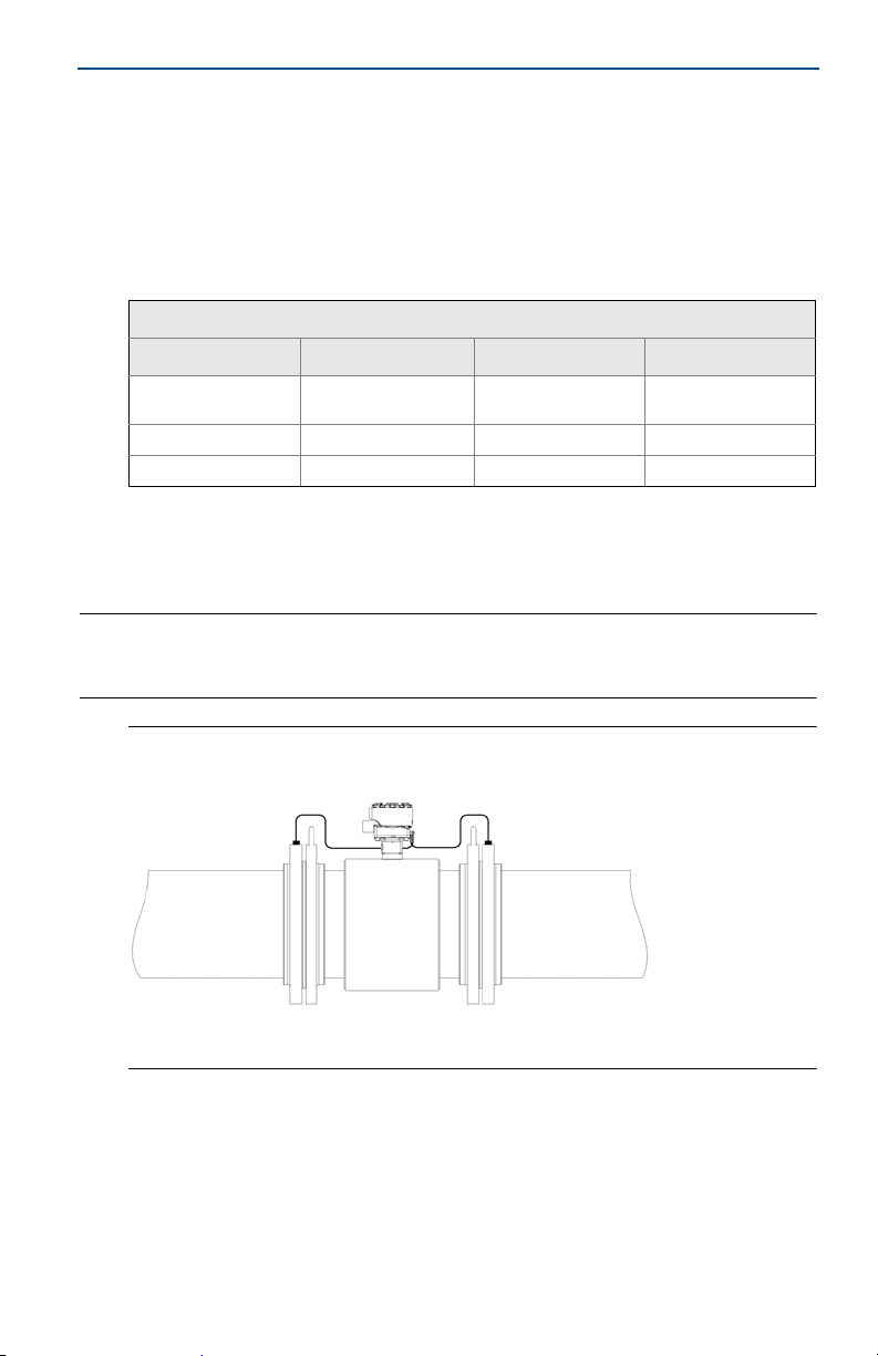
interference and noise in the system. See Figure 17.
Electrode cables should not be run together and should not be in the same
cable tray with power cables.
Output cables should not be run together with power cables.
Select conduit size appropriate to feed cables through to the flowmeter.
18
Page 19

March 2016
Quick Start Guide
Figure 17. Best Practice Conduit Preparation
A. Power
B. Output
C. Coil
D. Electrode
6.3 Connecting sensor to transmitter
Integral mount transmitters
Integral mount transmitters ordered with a sensor will be shipped assembled and
wired at the factory using an interconnecting cable (see Figure 18). Use only the
interconnecting cable provided by Emerson Process Management.
For replacement transmitters use the existing interconnecting cable from the
original assembly. Replacement cables are available.
Figure 18. Interconnecting Cables
Remote mount transmitters
Cables kits are available as individual component cables or as a combination
coil/electrode cable. Remote cables can be ordered direct from Rosemount using
the kit numbers shown in Table 9 and Table 11. Equivalent Alpha cable part
numbers are also provided as an alternative. To order cable, specify length as
quantity desired. Equal length of component cables is required.
Example: 25-feet = Qty (25) 08732-0065-0001
19
Page 20

Quick Start Guide
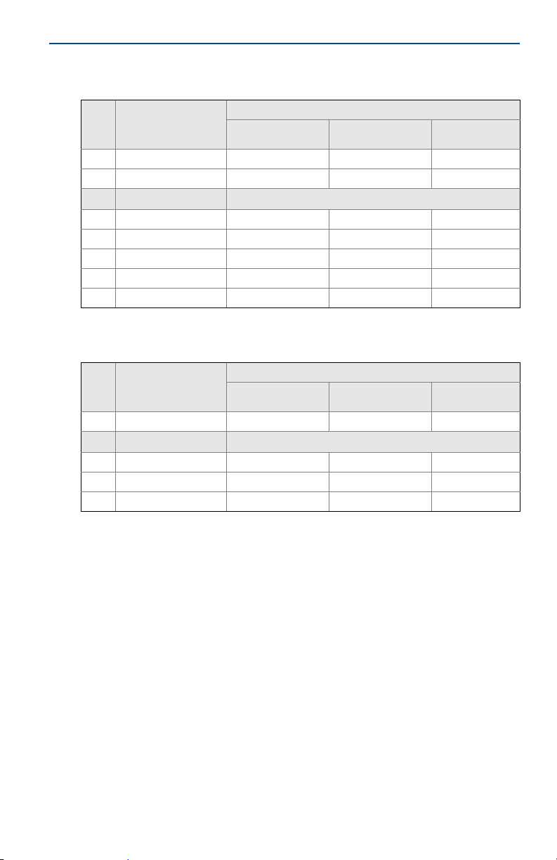
Table 9. Component Cable Kits
Standard temperature (-20 °C to 75 °C)
Cable kit number Description Individual cable Alpha p/n
08732-0065-0001
(feet)
08732-0065-0002
(meters)
08732-0065-0003
(feet)
08732-0065-0004
(meters)
Cable kit number
08732-0065-1001
(feet)
08732-0065-1002
(meters)
08732-0065-1003
(feet)
08732-0065-1004
(meters)
Kit, component cables, std temp.
(includes coil + electrode)
Kit, component cables, std temp.
(includes coil + electrode)
Kit, component cables, std temp.
(includes coil + i.s. electrode)
Kit, component cables, std temp.
(includes coil + i.s. electrode)
Extended temperature (-5 0 °C to 125 °C)
Description Individual cable
Kit, component cables, ext temp.
(includes coil + electrode)
Kit, component cables, ext temp.
(includes coil + electrode)
Kit, component cables, ext temp.
(includes coil + i.s. electrode)
Kit, component cables, ext temp.
(includes coil + i.s. electrode)
Coil
Electrode
Coil
Electrode
Coil
Intrinsically Safe Blue
Electrode
Coil
Intrinsically Safe Blue
Electrode
Coil
Electrode
Coil
Electrode
Coil
Intrinsically safe blue
Electrode
Coil
Intrinsically safe blue
Electrode
March 2016
518243
518245
518243
518245
518243
518245
518243
518245
Alpha p/n
840310
518189
840310
518189
840310
518189
840310
518189
Table 10. Combination Cable Kits
Coil and electrode cable (-20 °C to 80 °C)
Cable kit number Description
08732-0065-2001
20
(feet)
08732-0065-2002
(meters)
08732-0065-3001
(feet)
08732-0065-3002
(meters)
Kit, combination cable,
standard
Kit, combination cable
submersible
(80
(33-ft. Continuous)
°C dry/60 °C Wet)
Page 21

March 2016
1
2
3
C
B
A
C
B
A
19 18
17
D
A
B
C
Quick Start Guide
Cable requirements
Shielded twisted pairs or triads must be used. For installations using the individual
coil drive and electrode cable, see Figure 19. Cable lengths should be limited to
less than 500-feet (152 m). Consult your local Emerson representative for length
between 500–1000-feet (152-304 m). Equal length cable is required for each.
For installations using the combination coil drive/electrode cable,
see Figure 20. Combination cable lengths should be limited to less than 330-feet
(100 m).
Figure 19. Individual Component Cables
Coil drive Electrode
A. Outer jacket
B. Overlapping foil shield
C. Twisted stranded insulated conductors
Figure 20. Combination Coil and Electrode Cable
Cable
number
1 Red
2 Blue
3 Drain
17 Black
18 Yel lo w
19 White
Color
Cable
number
1 Red
2 Blue
3 Drain
17 Black
18 Yellow
19 White
D. Drain
E. Coil drive
F. E le ct rode
Color
A. Electrode shield-drain
B. Overlapping foil shield
C. Outer jacket
21
Page 22

Quick Start Guide
Component
Combination
Cable preparation
When preparing all wire connections, remove only the insulation required to fit
the wire completely under the terminal connection. Prepare the ends of the coil
drive and electrode cables as shown in Figure 21. Limit the unshielded wire length
to less than one inch on both the coil drive and electrode cables. Any length of
unsheathed conductor should be insulated. Excessive removal of insulation may
result in an unwanted electrical short to the transmitter housing or other wire
connections. Excessive unshielded lead length, or failure to connect cable shields
properly, may expose the unit to electrical noise, resulting in an unstable meter
reading.
Figure 21. Cable Ends
A. Coil
B. Electrode
March 2016
Shock Hazard
Potential shock hazard across remote junction box terminals 1 and 2 (40V).
Explosion Hazard
Electrodes exposed to process. Use only compatible transmitter and approved installation practices.
Figure 22. Remote Junction Box Views
A. Sensor
For complete sensor wiring diagrams,
reference Installation Drawing Rosemount 8750W-1052.
22
Page 23

March 2016
Quick Start Guide
6.4 Transmitter terminal block connections
Field mount transmitter
Remove the back cover of the transmitter to access the terminal block.
See Figure 23 for terminal identification. To connect pulse output and/or discrete
input/output consult the comprehensive product manual.
Figure 23. Field Mount Terminal Block Connections
Wall mount transmitter
Open the lower cover of the transmitter to access the terminal block.
See Figure 24 for terminal identification or inside the over for wiring terminal
identification. To connect the pulse output and or discrete input/output, consult
the comprehensive product manual.
Figure 24. Wall Mount Transmitter Terminal Block Connections
23
Page 24

Quick Start Guide
6.5 Analog output
Field mount transmitter
The analog output signal is a 4–20mA current loop. The loop can be powered
internally or externally via a hardware switch located on the front of the
electronics stack. The switch is set to internal power when shipped from the
factory. For field mount units with a display, the LOI must be removed to change
switch position.
For HART communication a minimum resistance of 250 ohms is required. It is
recommended to use individually shielded twisted pair cable. The minimum
conductor size is 0.51mm diameter (#24 AWG) for cable runs less than 5,000-feet
(1,500m) and 0.81mm diameter (#20 AWG) for longer distances.
Internal power
The 4-20mA analog signal is a 24VDC active output.
Maximum allowable loop resistance is 500 ohms.
Wire terminal 1 (+) and terminal 2 (-). See Figure 25.
Figure 25. Field Mount Transmitter Analog Wiring - Internal Power
March 2016
NOTICE
Terminal polarity for the analog output is reversed between internally and externally powered.
External power
The 4–20mA analog signal is passive and must be powered from an external
power source. Power at the transmitter terminals must be 10.8–30VDC.
Wire terminal 1 (-) and terminal 2 (+). See Figure 26.
24
Page 25

March 2016
A
Power supply (Volts)
Load (Ohms)
Operating
region
600
10.8
30
400
200
0
Figure 26. Field Mount Transmitter Analog Wiring - External Power
A. Power supply
Analog loop load limitations
Maximum loop resistance is determined by the voltage level of the external
power supply, as described in Figure 27.
Figure 27. Field Mount Transmitter Analog Loop Load Limitations
Quick Start Guide
= 31.25 (Vps – 10.8)
R
max
Vps = Power supply voltage (Volts)
= Maximum loop resistance (Ohms)
R
max
Wall mount transmitter
The analog output signal is a 4–20mA current loop. The loop can be powered
internally or externally via a hardware switch. The switch is set to internal power
when shipped from the factory.
For HART communication a minimum resistance of 250 ohms is required. It is
recommended to use individually shielded twisted pair cable. The minimum
conductor size is 0.51mm diameter (#24 AWG) for cable runs less than 5,000-feet
(1,500m) and 0.81mm diameter (#20 AWG) for longer distances.
Internal power
The 4–20mA analog signal is a 24VDC active output.
Maximum allowable loop resistance is 500 ohms.
25
Page 26

Quick Start Guide
Power supply (Volts)
Load (Ohms)
Operating
region
1000
10.8
30
750
250
0
500
External power
The 4–20 mA analog signal is powered from an external power source. HART
multidrop installations require a 10–30VDC external analog power source.
Figure 28. Wall Mount Transmitter Analog Wiring
A. +4–20 mA
B. -4
–20 mA
Analog loop load limitations
Maximum loop resistance is determined by the voltage level of the external
power supply, as described in Figure 29.
Figure 29. Wall Mount Transmitter Analog Loop Load Limitations
March 2016
= 52.08 (Vps – 10.8)
R
max
= Power supply voltage (Volts)
V
ps
= Maximum loop resistance (Ohms)
R
max
6.6 Powering the transmitter
The transmitter is available in two models. The AC powered transmitter is
designed to be powered by 90–250VAC (50/60Hz). The DC powered transmitter
is designed to be powered by 12
Rosemount 8750W, be sure to have the proper power supply, conduit, and other
accessories. Wire the transmitter according to national, local, and plant electrical
requirements for the supply voltage.
See Figure 30 or Figure 32.
26
–42VDC. Before connecting power to the
Page 27

March 2016
Supply current (Amps)
Power supply (VDC)
Supply current (Amps)
Power supply (VDC)
Figure 30. Field Mount Transmitter DC Power Requirements
Peak inrush is 42A at 42VDC supply, lasting approximately 1ms.
Inrush for other supply voltages can be estimated with:
Inrush (Amps) = Supply (Volts)/1.0
Quick Start Guide
Figure 31. Wall Mount Transmitter DC Power Requirements
27
Page 28

Quick Start Guide
Supply current (Amps)
Power supply (VAC)
Power supply (VAC)
Apparent power (VA)
Figure 32. Field Mount Transmitter AC Power Requirements
March 2016
Peak inrush is 35.7A at 250VAC supply, lasting approximately 1ms.
Inrush for other supply voltages can be estimated with:
Inrush (Amps) = Supply (Volts)/7.0
28
Page 29

Supply current (Amps)
Apparent power (VA)
Power supply (VAC)
Power supply (VAC)
March 2016
Figure 33. Wall Mount Transmitter AC Power Requirements
Quick Start Guide
29
Page 30

Quick Start Guide
Supply wire requirements
Use 10–18 AWG wire rated for the proper temperature of the application. For
wire 10–14 AWG use lugs or other appropriate connectors. For connections in
ambient temperatures above 122 °F (50 °C), use a wire rated for 194 °F (90 °C). For
DC powered transmitters with extended cable lengths, verify that there is a
minimum of 12VDC at the terminals of the transmitter with the device under
load.
Disconnects
Connect the device through an external disconnect or circuit breaker per national
and local electrical code.
Installation category
The installation category for the Rosemount 8750W is OVERVOLTAGE CAT II.
Overcurrent protection
The Rosemount 8750W Transmitter requires overcurrent protection of the
supply lines. Fuse rating and compatible fuses are shown in Table 11 and
Table 12.
Table 11. Field Mount Transmitter Fuse Requirements
Input voltage Fuse ratin g Compatible fuse
90-250VAC rms
12-42VDC
1 Amp, 250V, I2t ≥ 1.5 A2s Rating,
Fas t Act ing
3 Amp, 250V, I2t ≥ 14 A2s Rating,
Fas t Act ing
Bussman AGC-1, Littelfuse 31201.5HXP
Bel Fuse 3AG 3-R, Littelfuse 312003P,
Schurter 0034.5135
March 2016
Table 12. Wall Mount Transmitter Fuse Requirements
Input voltage Fuse rating Compatible fuse
90–250VAC 2 Amp, fast acting Bussman AGC-2
12–42VDC 3 Amp, fast acting Bussman AGC-3
Field mount transmitter power terminals
See Figure 23 for field mount terminal connections.
For AC powered transmitter (90
Connect AC Neutral to terminal 9 (AC N/L2) and AC Line to terminal 10
(AC/L1).
For DC powered transmitter
Connect negative to terminal 9 (DC -) and positive to terminal 10 (DC +).
DC powered units may draw up to 1.2A.
30
–250VAC, 50/60 Hz)
Page 31

March 2016
Quick Start Guide
Wall mount transmitter power terminals
See Figure 24 for wall mount transmitter terminal connections.
For AC powered transmitter (90
Connect AC Neutral to terminal N and AC Line to terminal L1.
–250VAC, 50/60 Hz)
For DC powered transmitter
Connect DC- to terminal N and DC+ to terminal L1.
Field mount transmitter cover jam screw
For flow meters shipped with a cover jam screw, the screw should be installed
after the instrument has been wired and powered up. Follow the steps to install
the cover jam screw:
1. Verify the cover jam screw is completely threaded into the housing.
2. Install the housing cover and verify the cover is tight against the housing.
3. Using a 2.5 mm hex wrench, loosen the jam screw until it contacts the
transmitter cover.
4. Turn the jam screw an additional
Note
Application of excessive torque may strip the threads.
5. Verify the cover cannot be removed.
1
/2 turn counterclockwise to secure the cover.
7.0 Basic configuration
Once the magnetic flowmeter is installed and power has been supplied, the
transmitter must be configured through the basic setup. These parameters can
be configured through either a local operator interface or a HART communication
device. Configuration settings are saved in nonvolatile memory within the
transmitter. A table of all the parameters is located in Table 13. Descriptions of
the more advanced functions are included in the comprehensive product manual.
7.1 Basic setup
Ta g
Tag is the quickest and shortest way of identifying and distinguishing between
transmitters. Transmitters can be tagged according to the requirements of your
application. The tag may be up to eight characters long.
Flow units (PV)
The flow units variable specifies the format in which the flow rate will be
displayed. Units should be selected to meet your particular metering needs.
Line size
The line size (sensor size) must be set to match the actual sensor connected to the
transmitter. The size must be specified in inches.
31
Page 32

Quick Start Guide
URV (upper range value)
The URV sets the 20 mA point for the analog output. This value is typically set to
full-scale flow. The units that appear will be the same as those selected under the
flow units parameter. The URV may be set between –39.3 ft/s to 39.3 ft/s
(–12 m/s to 12 m/s). There must be at least 1 ft/s (0.3 m/s) span between the URV
and LRV.
LRV (lower range value)
The LRV sets the 4 mA point for the analog output. This value is typically set to
zero flow. The units that appear will be the same as those selected under the flow
units parameter. The LRV may be set between –39.3 ft/s to 39.3 ft/s
(–12 m/s to 12 m/s). There must be at least 1 ft/s (0.3 m/s) span between the URV
and LRV.
March 2016
32
Page 33

March 2016
Quick Start Guide
7.2 Calibration number
The sensor calibration number is a 16-digit number generated at the Rosemount
factory during flow calibration and is unique to each sensor and is located in the
sensor tag.
Table 13. Handheld Fast Keys (Field Communicator)
Function HART fast keys
Process variables 1, 1
Primary Variable (PV) 1, 1, 1
PV Percent of range (PV % rnge) 1, 1, 2
PV Analog Output (AO) (PV Loop current) 1, 1, 3
Tot aliz er s et-u p 1, 1, 4
Totalizer units 1, 1, 4, 1
Gross total 1, 1, 4, 2
Net total 1, 1, 4, 3
Reverse total 1, 1, 4, 4
Start totalizer 1, 1, 4, 5
Stop totalizer 1, 1, 4, 6
Reset totalizer 1, 1, 4, 7
Pulse output 1, 1, 5
Basic setup 1, 3
Tag 1, 3, 1
Flow units 1, 3, 2
PV units 1, 3, 2, 1
Special units 1, 3, 2, 2
Line size 1, 3, 3
PV Upper Range Value (URV) 1, 3, 4
PV Lower Range Value (LRV) 1, 3, 5
Calibration number 1, 3, 6
PV Damping 1, 3, 7
Review 1, 5
7.3 Field mount transmitter local operator interface
To activate the optional Local Operator Interface (LOI), press the DOWN arrow
two times. Use the UP, DOWN, LEFT, and RIGHT arrows to navigate the menu
structure. A map of the LOI menu structure is shown on Figure 34. The display can
be locked to prevent unintentional configuration changes. The display lock can
be activated through a HART communication device, or by holding the UP arrow
for three seconds and then following the on-screen instructions. When the
display lock is activated, a lock symbol will appear in the lower right hand corner
of the display. To deactivate the display lock, hold the UP arrow for three seconds
and follow the on-screen instructions. Once deactivated, the lock symbol will no
longer appear in the lower right hand corner of the display.
33
Page 34

Quick Start Guide
p
y
March 2016
Figure 34. Field Mount Transmitter Local Operator Interface (LOI) Menu Tree
ec Coating
E mpty P ipe
Process Noise
G round/W ir ing
El
Elect Temp
Reverse Flow
Self Test
A O L oop Test
Pulse Out Test
E mpty P ipe ElFlow Limit 1
Cont Meter Ver
ec T emp
Coil Resist
Coil Inductnce
Total Limit
Flow Limit 2
Values
Reset Baseline
E lectr ode Res
No Flow
Flowing, Full
E mpty P ipe
Continual
Manual Measure
Continual Meas
LOI Err Mask
Disp Auto Lock
Flow Display
Total Display
L anguage
Flow Limit 2
Total Limit
Diag Alert
Variable Map
Poll Address
Req Preams
Resp Preams
Burst Mode
Burst Command
Operating Mode
SP Config
C oil F requency
PV Damping
Lo-Flow Cuto
Pulse Scaling
Pulse Width
Pulse Mode
DI/O 1
DO 2
Test
Flow Limit 1
Recall V alues
R un Meter Ver
G round/W ir ingPrElec Coating
Diag Controls
Basic Diag
A dvanced D iag
Diagnostics
Variables
V iew Results
Sensr Baseline
ocess Noise
Trims
Test Criteria
M easurements
Meter Verify
4-20 mA V erif y
Licensing
PV Units
Status
E mpty P ipe
4-20 mA V erif y
View Results
D/A Trim
Digital T rim
37Hz Auto Zero
C oil F requency
Special Units
Totalize Units
Tag
Flow Units
L ine S ize
PV URV
PV LRV
Basic Setup
Elec Coating
El ect Temp
Line Noise
5Hz S NR
37Hz S NR
Signal Power
MV R esults
37Hz Auto Zero
Coil Current
PV URV
PV LRV
PV AO
Alarm Type
Test
Alarm Level
AO Diag Alarm
Universal Trim
Proc Density
PV LSL
PV USL
PV Min Span
Cal Number
PV Damping
Analog
Pulse
DI/DO Config
verse F low
Totalizer ReAlarm Level
More Params
Output C onfi g
Detai led S etup
HART
LOI Config
Sig Processing
la
Totalize Units
Total Dis
Device Reset
Device Info
Software Rev
Final Asmbl #
Tag
Tag
Description
Message
Device ID
PV Sensor S/N
Sensor
Write Protect
R evis ion Num
34
Page 35

March 2016
1. Device
Setup
2. PV
3. PV L
oop
Current
4. PV LRV
5. PV URV
1. PV
2. PV % Range
3. PV Loop Current4. Totalizer Setup
5.
Pulse Output
1. Totalizer Units
2. Gross Total
3. Net Total
4. Reverse Total
5. Start Totalizer
6. Stop Totalizer
7. Reset Totalize
r
1. Diagnostic Controls
2. Basic Diagnostics
3.
Advanced Diagnostics
4. Diagnostic Variables
5. Trims6. View Status
1. Process
Variables
2. Diagnostics
3. Basic
Setup
4. Detailed
Setup
5. Review
1. Self Test
2. AO Loop Test
3. Pulse Output Loop Test
4. Tune Empty
Pipe
5. Electronics Temp
6. Flow Limit 1
7. Flow Limit 2
8. Total Limi
t
1. EP Value
2. Electronics Temp
3. Line Noise
4.
5 Hz SNR
5.
37 Hz SNR
6. Signal Power
7. 8714i Results
1. PV Units
2. Special Units
1. Volume Unit
2. Base Volume Unit
3. Conversion Number
4. Base Time Unit
5. Flow Rate Unit
1. Analog Output
2. Pulse Output
3. Digital I/O
4. Reverse Flow
5. Totalizer Setup
6. Alarm Le
vels
7. HART
Out
p
u
t
1. PV URV
2. PV LRV
3. PV Loop Current4.
PV Alarm Ty
pe
5.
AO Loop Test
6. D/A Trim
7. Scaled D/A Trim
8. Alarm Level
1. Pulse Scaling
2. Pulse Width
3. Pulse Output Loop Test
1. Totalizer Units
2. Gross Total
3. Net Total
4. Reverse Total
5. Start Totalizer
6. Stop Totalizer
7. Reset Totalize
r
1. Variable Mapping
2.
Poll Address
3. # of Req Preams
4. # of Resp Preams
5. Burst Mode
6. Burst Option
1. Operating Mode
2.
Man Config DSP
3. Coil Drive Freq
4. Low Flow Cutoff
5. PV Damp
ing
1. Coil Drive Freq
2. Density Value
3. PV USL
4. PV LSL
5. PV Min S
p
an
1. Additional Params
2. Configure Output
3. Signal Processing
4. Universal Trim
5. Device Info
1. DI/DO 1
2. DO 2
3. Flow Limit 1
4. Flow Limit 2
5. Total Limit
6. Diagnostic Status Aler
t
1. Tag
2.
Flow Units
3. Line Size
4. PV URV
5. PV LRV
6. Calibration Number
7. PV Dam
p
in
g
1. Flange Type
2.
Flange Materi
al
3.
Electrode Ty
pe
4.
Electrode Material
5. Liner Material
1. Manufacturer
2. Tag3.
Descriptor
4. Message
5. Date
6. Device ID
7. PV Sensor S/N
8. Flowtube Tag
9. Write Pr
otect
-
Revision No.
- Construction Materials
1. Universal Rev
2. Transmitter Rev
3. Software Rev
4. Final Assembly
#
1. Status
2. Samples
3. % Limit
4. Time Limit
1. D/A Trim
2. Scaled D/A Trim
3. Digital Trim
4. Auto Zero
5. Universal Trim
1. 8714i Cal Verification
2. Licensing
1. Run 8714i Verification
2.
8714i Results
3. Flowtube Signature
4. Set Pass/Fail Criteria
5. Measurements
1. Signature Values
2. Re-Signature Meter
3. Recall Last Saved Values
1. License Status
2. License Key
1. Device ID
2. License Key
1. PV is
2. SV is
3. TV
is
4. QV is
1. Coil Resistance
2. Coil Signature
3. Electrode Resistance
1. No Flow Limit
2. Flowing, Limit
3. Empty Pipe Limit
1. Test Condition
2. Test C
riteria
3. 8714i Test Result
4. Simulated Velocity
5. Actual Velocity
6. Velocity Deviation
7. Xmtr Cal Test Result
8. Tube Cal Deviation
9. Tube Cal Test Result
- Coil Circuit Test Result
- Electrode Circuit Test
Resul
1. Test Condition
2. Test C
riteria
3. 8714i Test Result
4. Simulated Velocity
5. Actual Velocity
6. Velocity Deviation
7. Xmtr Cal Test Result
8. Tube Cal Deviation
9. Tube Cal Test Result
- Coil Circuit Test Result
- Electrode Circuit Test
Resul
1. Total Control
2. Total Mode
3. Total High Limit
4. Total Low Limit
5. Total Limit Hysteresis
1. Control 2
2. M
ode 2
3.
High Limit 2
4. Low Limi
t 2
5. Flow Li
mit Hysteresis
1. Control 1
2.
M
ode 1
3.
High Limit 1
4. Low Limi
t 1
5. Flow Li
mit Hysteresis
1. Configure I/O 1
2. DIO 1 Control3.
Digital Input 1
4. Digital Output 1
1. Coil Resistance
2. Coil Signature
3. Electrode Resistance
1. Total Control
2. Total Mode
3. Total High Limit
4. Total Low Limit
5. Total Limit Hysteresis
1. Control 2
2. M
ode 2
3.
High Limit 2
4. Low Limi
t 2
5. Flow Li
mit Hysteresis
1. Control 1
2. M
ode 1
3.
High Limit 1
4. Low Limi
t 1
5. Flow Limit Hysteresis
Empty Pipe On/Off
Process Noise On//Off
Grounding/Wiring On/Off
Electronics Temp On/Off
Process Noise Detect On/Off
Line Noise Detection On//Off
Digital I/O On/Off
8714i On/Off
Reverse Flow
Zero Flow
Transmitter Fault
Empty Pipe
Flow Limit 1
Flow Limit 2
Diag Status Alert
Totalizer Limi
t
Electronics Failure On/Off
Coil Open Circuit On/Off
Empty Pipe On/Off
Reverse Flow On/Off
Ground/Wiring Fault On/Off
High Process Noise On/Off
Elect Tem
p
Out of Ra.. On/Off
1. EP Value
2. EP Trig. Level3.
EP
Counts
Quick Start Guide
Figure 35. Wall Mount Transmitter Local Operator Interface (LOI) Menu Tree
t
t
35
Page 36

Quick Start Guide
8.0 Product Certifications
Table 14. Rosemount 8750W Platform
March 2016
Order
code
-Ordinary Locations
Z1
ND ATEX Dust EU DEKRA 15ATEX0003 X
Z2
Z3
DIP (Dust-Ignitionproof) Class II and III,
Z5
CSA, Class I Div 2 for Non-Flammable
Z6
Z7
NF IECEx Dust Global DEKRA IECEx DEK 15.0001X
Z9
1. Complies with only the local country Product safety, electromagnetic, pressure and other applicable
regulations. Cannot be used in a classified or zoned hazardous location environment.
2. Customs union (Russia, Belarus and Kazakhstan).
3. Planned submittal or in process with agency.
Platform rating Re gion Agency Certification number
(1)
ATEX Non-Sparking and Dust for
Non-Flammable Fluids
InMetro Non-Sparking and Dust for
Non-Flammable Fluids
NEPSI Non-Sparking and Dust for
Non-Flammable Fluids
Non-Incendive, Class I Div 2 for
IECEx Non-Sparking and Dust for
KTL Non-Sparking and Dust for
Div 1.
Non-Flammable Fluids
Fluids; DIP, NI
Non-Flammable Fluids
Non-Flammable Fluids
USA,
Canada
EU, CU
EU DEKRA 15ATEX0003 X
Brazil PENDING
China NEPSI GYJ15.1228X
USA FM 3030548
USA and
Canada
Global DEKRA IECEx DEK 15.0001X
Korea KTL
FM or CSA
and EAC
(2)
(3)
CSA 70030489
(3)
3030548(FM) or
70030489(CSA)
PENDING
PENDING
36
Page 37

March 2016
Table 15. Approval Markings and Logos
Quick Start Guide
Symbol
(1)
Marking or
symbol name
CE European Union
ATE X Eur ope an U nio n
C-tick Australia
FM Approved United States
CSA
Eurasian
Conformity
(EAC)
INMETRO Brazil
NEPSI China
Region
US = Uni ted
States
C = Canada
Eurasian
Customs Union
(Russia, Belar us
and Kazakhstan)
Meaning of marking or symbol
Compliance with all applicable European Union
Directives.
Compliance with Equipment and Protective
systems intended for use in Potentially Explosive
Atmospheres directive (ATEX) (94/9/EC).
Compliance with Australian applicable
electromagnetic compatibility standards.
Compliance with the applicable ANSI standards.
Indicates that the product was tested and has
met the applicable certification requirements
for the noted countries.
Compliance with all of the applicable technical
regulations of the EAC Customs Union.
Compliance with all of the applicable technical
regulations of Brazil.
Compliance with all of the applicable technical
regulations of China.
KTL Korea
1.Ordinary Location labels will be marked with CE, C-tick, FM, CSA, and EAC logos.
Compliance with all of the applicable technical
regulations of Korea.
37
Page 38

Quick Start Guide
8.1 European Directive Information
A copy of the EC Declarat ion of Confor mity can be found at t he end of the Quick Star t Guide.
The most recent revision of the EC Declaration of Conformity can be found at
EmersonProcess.com/Rosemount.
Electro Magnetic Compatibility (EMC) (2004/108/EC) and
(2014/30/EU)
EN 61326-1: 2013
Low Voltage Directive (LVD) (2006/95/EC) and (2014/35/EU)
EN 61010-1: 2010
Ingress protection rating for dust and water
Degree of protection, per EN-IEC 60079-0 and EN-IEC 60529: IP66
Degree of protection, per EN-IEC 60079-0 and EN-IEC 60529: IP66, IP68 (10m, 48h)
Degree of protection, per EN-IEC 60079-0 and ISO 20653: IP69K
European Pressure Equipment Directive (PED) (97/23/EC) and
(2014/68/EU)
PED Certification requires the “PD” option code.
CE marked models that are ordered without the “PD” option will be marked “Not Complaint
to (97/23/EC and 2014/68/EU)”
Mandatory CE-marking with notified body number 0575 or 2460, for all flowtubes is located
on the flowmeter label.
Category I assessed for conformity per module A procedures.
Categories II - III assessed for conformity per module H procedures.
QS Certificate of Assessment
EC No. 4741-2014-CE-HOU-DNV: Module H Conformity Assessment
(1)
(3)
March 2016
(2)
Rosemount 8750W Flanged Flowtubes
Line size 40 mm to 600 mm (11/2-in to 24-in)
EN 1092-1 flanges and ASME B16.5 class 150 and ASME B16.5 Class 300 flanges.
Also available in ASME B16.5 Class 600 flanges in limited line sizes.
All other Rosemount Flanged Flowtubes - line sizes of 25 mm (1-in.) and less: Sound
Engineering Practice (SEP).
Flowtubes that are SEP are outside the scope of PED and cannot be marked for compliance
with PED.
1. The transmitter is rated IP66 when integral or remote mounted, it is not I P68 nor IP69K rated.
2. The IP68 rating only applies to the flowtube and the remote junction box when the transmitter is remotely
mounted. The IP 68 rating is only valid at a depth of 10 meters for 48 hours.
3. The IP69K rating only applies to the flowtube and the remote junction box when the transmitter is
remotely mounted. The temperature K = 80 ° C.
38
Page 39

March 2016
Quick Start Guide
8.2 Certifications
Factory Mutual (FM)
Ordinary Location Certification for FM Approvals
As standard, the transmitter and flowtube have been examined and tested to determine
that the design meets basic electrical, mechanical, and fire protection requirements by FM
Approvals, a nationally recognized testing laboratory (NRTL) as accredited by the Federal
Occupational Safety and Health Administration (OSHA).
Rosemount 8750W Magnetic Flowtube and Transmitter
Z5 All Flowtubes and Integral or Remote Mount Transmitters
(Transmitter mount codes T or R)
Non-Incendive for Class I, Division 2, Groups ABCD: T4 Dust-Ignition Proof for
Class II/III, Division 1, Groups EFG: T5 -29 °C ≤ T
Enclosure Type 4X, IP66/68 (IP68 flowtube only with Remote mount transmitter)
Install per drawing 8750W-1052.
Special Condition for Safe Use (X):
1. Flowtube to be used only in a non-flammable process.
Rosemount 8750W Magnetic Flowtube and Transmitter
Z5 All Flowtubes and Wall Mount Transmitter (Transmitter mount code W)
Non-Incendive for Class I, Division 2, Groups ABCD: T4 Dust-Ignition Proof for
Class II/III, Division 1, Groups EFG: T4-29 °C ≤ T
Enclosure Type 4X, IP66/68 (IP68 flowtube only)
Install per drawing 8750W-1052.
Special Condition for Safe Use (X):
1. Flowtube to be used only in a non-flammable process.
≤ 60 °C
a
≤ 40 °C
a
CSA
Ordinary Location Certification for FM Approvals
As standard, the transmitter and flowtube have been examined and tested to determine
that the design meets basic electrical, mechanical, and fire protection requirements by FM
Approvals, a nationally recognized testing laboratory (NRTL) as accredited by the Federal
Occupational Safety and Health Administration (OSHA).
Rosemount 8750W Magnetic Flowtube and Transmitter
Z6 Non-Incendive for Class I, Division 2, Groups ABCD: T4
Dust-Ignition Proof for Class II/III, Division 1, Groups EFG: T4 -29 °C ≤ T
(Transmitter mount codes T or R)
-29 °C ≤ T
Enclosure Type 4X, IP66/68/69K
Install per drawing 8750W-1052.
Special Condition for Safe Use (X):
1. Flowtube to be used only in a non-flammable process.
≤ 40 °C (Transmitter mount code W)
a
(1)
≤ 60 °C
a
39
Page 40

Quick Start Guide
1. The transmitter is rated IP66 when integral or remote mounted, it is not I P68 nor IP69K rated. The IP68
rating only applies to the flowtube and the remote junction b ox when the transmitter is remotely mounted.
The IP68 rating is only valid at a depth of 10 meters for 48 hours. The IP69K rating only applies to the
flowtube and the remote junction box when the transmitter is remotely mounted. The temperature K = 80 °C.
March 2016
40
Page 41

March 2016
Figure 36. Rosemount 8750W Declaration of Conformity
Quick Start Guide
41
Page 42

Quick Start Guide
March 2016
42
Page 43

March 2016
Quick Start Guide
43
Page 44

Quick Start Guide
8.3 IEC EX & ATEX
1. Equipment markings:
a. Type Examination Certificate (ATEX): DEKRA 15ATEX0003 X
b. Certificate of Conformity (IECEx): IECEx DEK 15.0001X
2. Required documentation:
a. 8750W-2052 Installation Drawing Model 8750W ATE X/IECEx Hazardous (Ex) Locations
3. Referenced documentation:
a. 00825-0300-4750.pdf, Quick Installation Guide
b. 00809-0300-4750.pdf, Reference Manual
c. 8750W-AP01, Approvals Document
d. 8750W-1504 Installation Drawing, 8750W Transmitter Wiring
4. The Required and Referenced Documents listed above address the following items:
a. Instructions for safety i.e.
i. Putting into service
ii. Use
iii. Assembling and dismantling
iv. Maintenance, overhaul and repair
v. I nsta lla tio n
vi. Adjustment
b. Where necessary, training instructions
c. Details which allow a decision to be made as to whether the equipment can be used
safely in the intended area under the expected operating conditions.
March 2016
44
Page 45

March 2016
d. Electrical parameters, maximum surface temperatures and other limit values.
i. Electrical
1. See document 8750W-2052
Rosemount 8750W Flow Transmitter
Power input
Pulsed circuit
4-20 mA output
circuit
®
Modbus
Um 250 V
90 - 250 VAC, 0.45 A , 40 VA
12 - 42 VDC, 1.2 A, 15 W
Internally powered (Active): outputs up to 12 VDC, 12.1 mA, 73 mW
Externally powered (Passive): input up to 28 VDC, 100 mA, 1 W
Internally Powered (Active): outputs up to 25 mA, 24 VDC, 600 mW
Externally Powered (Passive): input up to 25 mA, 30 VDC, 750 mW
Internally Powered (Active): outputs up to 100 mA, 3.3 VDC, 100 mW
Quick Start Guide
Coil excitation
output
500 mA, 40 V
Rosemount 8750W Flowtube
Coil excitation
input
Electrode circuit 5 V, 200 uA, 1 m W
1. Provided by the transmitter.
500 mA, 40 V
max
max
, 9 W
(1)
, 20 W
max
max
Special Conditions for Safe Use (X):
1. When “Special Paint Systems” are applied, instructions for safe use
regarding potential electrostatic charging hazard have to be followed.
2. Terminals 1,2,3,4, for data communication, cannot withstand the 500 V
isolation test between signal and ground, due to integral transient
protection. This must be taken into account upon installation.
3. Conduit entries must be installed to maintain the enclosure ingress rating
of IP66 (Transmitter and Flow Tube), IP68 or IP69K (Flow Tube) as
applicable.
4. The flow tube and transmitter are not allowed to be thermally insulated.
e. Where necessary, the essential characteristics of tools which may be fitted to the
equipment
i. No proprietary tools required.
f. List of the standards, including the issue date, with which the equipment is declared to
comply:
i. ATEX - EN 60079-0 : 2012 + A11 : 2013, EN 60079-11 : 2012, EN 60079-15 : 2010,
EN 60079-31 : 2014
ii. IECEx - IEC 60079-0: 2011, IEC 60079-11: 2011, IEC 60079-15: 2010, IEC 60079-31:
2013
45
Page 46

Quick Start Guide
g. Supply wire requirements;
Use 10–18 AWG wire rated for the proper temperature of the application.
For wire 10–14 AWG use lugs or other appropriate connectors. For connections in
ambient temperatures above 122 °F (50 °C), use a wire rated for 194 °F (90 °C).
h. Contact address:
Rosemount Inc.
12001 Technology Drive
Eden Prairie,
MN 55344
United States of America
March 2016
46
Page 47

March 2016
Quick Start Guide
Table 16. Nomenclature Magnetic Flow Meter System Model Rosemount 8750W
and Electrical Data
8750W … R 1 A 2 … F 005 … Z1 … M4 … AX … V1 … RH50
I II III IV V VI VII VIII IX X XI IX
Designation Explanation Va lue Explanation
I Model 8750W Flow Meter System Model 8750W
II
III
IV
Transmitter
mount
Transmitter power
supply
Transmitter
outputs
VConduit entries
VI Electrode type
VII Line size
VIII Safety approvals
IX
X
Transmitter
display
Transmitter
discrete
input/output
XI Specials paint Vx Special paint systems
XII
Remote cable
option
R
Remote mount
T
Integral mount
1
AC (90
2
A
M
0
1 or 4
2 or 5
–250 Vac, 50/60 Hz), not for Ex nA
DC (12
–42 Vdc)
4–20 mA with digital HART Protocol and
scalable pulse output
Modbus RS-485
Spare flow tube, no transmitter
1
/2–14 NPT female
CM20, M20 female
A, B, E, F0Seal of electrodes comply with IEC 61010-1.
Spare transmitter, no flow tube
1
005
480
000
Z1 ATEX
Z7 IECEx
ND ATEX II 3 D Ex tc IIIC T80 °C…T130 °C Dc
NF IECEx Ex tc IIIC T80 °C…T130 °C Dc
/2-in. NPS (15 mm)
to
to
48-in NPS (1200 mm)
Spare transmitter, no flow tube
II 3 GEx nA [ic] IIC T4 Gc
II 3 GEx nA ic IIC T5…T4 Gc
II 3 DEx tc IIIC T80 °C…T130 °C Dc
Ex nA [ic] IIC T4 Gc
Ex nA ic IIC T5…T4 Gc
Ex tc IIIC T80 °C…T130 °C Dc
(1)
(2)
(3)
(1)
(2)
(3)
(3)
(3)
M4M5LOI
Display
AX Two discrete channels (DI/DO 1, DO 2)
(4)
(5)
RTxx
RHxx
Standard temperature component
(5)
Extended temperature component
1. Model 8750W Transmitter DC Power Supply only.
2. Model 8750W Flow Tube only.
3. Model 8750W Transmitter AC and DC Power Supply and Model 8750W Flow Tube.
4. Subject to special conditions for safe use.
5. Length = xx min. 10-ft, max. 500-ft.
47
Page 48

Quick Start Guide
9.0 Installation and wiring drawings
March 2016
48
Page 49

March 2016
Quick Start Guide
49
Page 50

Quick Start Guide
March 2016
50
Page 51

March 2016
Quick Start Guide
51
Page 52

Global Headquarters
Emerson Process Management
6021 Innovation Blvd.
Shakopee, MN 55379, USA
+1 800 522 6277 or +1 303 527 5200
+1 303 530 8459
Flow.Support@Emerson.com
North America Regional Office
Emerson Process Management
7070 Winchester Circle
Boulder, CO 80301, USA
+1 800 522 6277 or +1 303 527 5200
+1 303 530 8459
Flow.Support@Emerson.com
Latin America Regional Office
Emerson Process Management
Multipark Office Center
Turrubares Building, 3rd & 4th floor
Guachipelin de Escazu, Costa Rica
+1 506 2505 6962
+1 954 846 5121
Flow.Support@Emerson.com
Europe Regional Office
Emerson Process Management Flow B.V.
Neonstraat 1
6718 WX Ede
The Netherlands
+31 (0) 318 495555
+31 (0) 318 495556
Flow.Support@Emerson.com
Asia Pacific Regional Office
Emerson Process Management Asia Pacific Pte Ltd
1 Pandan Crescent
Singapore 128461
+65 6777 8211
+65 6777 0947
APFlow.Support@Emerson.com
Middle East and Africa Regional Office
Emerson Process Management
Emerson FZE P.O. Box 17033,
Jebel Ali Free Zone - South 2
Dubai, United Arab Emirates
+971 4 8118100
+971 4 8865465
FlowTechnicalSupport@Emerson.com
*00825-0300-4750*
Quick Start Guide
00825-0300-4750, Rev CA
Linkedin.com/company/Emerson-Process-Management
Twitter.com/Rosemount_News
Facebook.com/Rosemount
Youtube.com/us er/RosemountMeasur ement
Google.com/+RosemountMeasurement
Standard Terms and Conditions of Sale can be found at
Emerson.com/en-us/pages/Terms-of-Use.aspx
The Emerson logo is a trademark and service mark of Emerson
Electric Co.
Rosemount and Rosemount logotype are trademarks of Emerson
Process Management
HART is a registered trademark of FieldComm Group.
Modbus is a registered trademark of Modicon, Inc.
All other marks are the property of their respective owners.
© 2016 Emerson Process Management. All rights reserved.
March 2016
 Loading...