

Rosemount 8712C, 8712U, 8712H Product Manual
00809-0100-4729
Model 8712C/U/H Magnetic
Flowmeter Transmitters
English
Rev. CA


Product Manual
Model 8712C/U/H
Magnetic Flowmeter
Transmitters
NOTICE
Read this manual before working with the product. For personal and system
safety, and for optimum product performance, make sure you thoroughly
understand the contents before installing, using, or maintaining this product.
Within the United States,Rosemount Inc. has two toll-freeassistance numbers.
Customer Central:
Technical support, quoting, and order-related questions
1-800-999-9307(
North American Response Center:
Equipment ser vice needs
1-800-654-7768(
Forequipmentservice orsupport needs outside the Uni ted States,contactyour
7:00 a.m. to 7:00 p.m. CST)
24 hours a day – Includes Canada)
Rosemount Inc.
8200 Market Boulevard
Chanhassen, MN 55317 USA
Tel 1-800-999-9307
Fax (952) 949-7001
© 2000 Rosemount, Inc.
http://www.rosemount.com
The products described in this document are NOT designed for
nuclear-qualified applications.
Using non-nuclear qualified products in applications that require
nuclear-qualified hardware or products may cause inaccurate readings.
For information on Rosemount nuclear-qualifiedproducts, contact your local
Rosemount sales representative.
SNF-0004
Rosemount, the Rosemount logotype, and SMART FAMILY are registered trademarks of Rosemount Inc.
PlantWeb is a trademark of the Fisher-Rosemount group of companies.
HART is a registered trademark of the HART Communication Foundation.
Hastelloy is a registered trademark of Haynes International.
Teflon and Tefzel are registered trademarks of E.I. du Pontde Nemours & Co.
Ryton is a registered trademark of Phillips Petroleum Co.
Cover Photo: 8712-006AB
Fisher-Rosemount satisfies all obligations coming from legislation
to harmonize product requirements in the European Union.
T
N
I
E
D
R
P
IN
U.
A.
S.


Table of Contents
SECTION 1
Introduction
SECTION 2
Installation
Manual Scope . . . . . . . . . . . . . . . . . . . . . . . . . . . . . . . . . . . . . . . . . . 1-1
System Description . . . . . . . . . . . . . . . . . . . . . . . . . . . . . . . . . . . . . 1-2
Introduction . . . . . . . . . . . . . . . . . . . . . . . . . . . . . . . . . . . . . . . . . . . 2-1
Safety Messages . . . . . . . . . . . . . . . . . . . . . . . . . . . . . . . . . . . . . . . . 2-1
Transmitter Symbols . . . . . . . . . . . . . . . . . . . . . . . . . . . . . . . . . . . . 2-1
Pre-Installation . . . . . . . . . . . . . . . . . . . . . . . . . . . . . . . . . . . . . . . . 2-2
Mechanical Considerations . . . . . . . . . . . . . . . . . . . . . . . . . . . . 2-2
Environmental Considerations . . . . . . . . . . . . . . . . . . . . . . . . . 2-3
Installation Procedures . . . . . . . . . . . . . . . . . . . . . . . . . . . . . . . . . . 2-3
Mount the Transmitter . . . . . . . . . . . . . . . . . . . . . . . . . . . . . . . 2-3
Identify Options and Configurations . . . . . . . . . . . . . . . . . . . . 2-3
Hardware Jumpers/Switches . . . . . . . . . . . . . . . . . . . . . . . . . . 2-4
Electrical Considerations . . . . . . . . . . . . . . . . . . . . . . . . . . . . . 2-5
Conduit Connections . . . . . . . . . . . . . . . . . . . . . . . . . . . . . . . . . 2-6
Conduit Installation . . . . . . . . . . . . . . . . . . . . . . . . . . . . . . . . . 2-6
Options, Considerations, and Procedures . . . . . . . . . . . . . . . . . . . . 2-9
Connect Transmitter Power . . . . . . . . . . . . . . . . . . . . . . . . . . . 2-9
Connect 4–20 mA Loop External Power Source . . . . . . . . . . . . 2-10
Connect Pulse Output Power Source . . . . . . . . . . . . . . . . . . . . 2-11
Connect Auxiliary Output Control . . . . . . . . . . . . . . . . . . . . . . 2-12
Connect Positive Zero Return (PZR) Power Source . . . . . . . . . 2-13
Flowtube Connections . . . . . . . . . . . . . . . . . . . . . . . . . . . . . . . . . . . 2-14
Rosemount Flowtubes . . . . . . . . . . . . . . . . . . . . . . . . . . . . . . . . 2-14
Flowtubes of Other Manufacturers . . . . . . . . . . . . . . . . . . . . . 2-14
Applying Power . . . . . . . . . . . . . . . . . . . . . . . . . . . . . . . . . . . . . . . . 2-15
Software Installation . . . . . . . . . . . . . . . . . . . . . . . . . . . . . . . . . . . . 2-15
Installation Check and Guide . . . . . . . . . . . . . . . . . . . . . . . . . . 2-16
SECTION 3
Local Operator
Interface
SECTION 4
Device Software
Functions
Local Operator Interface . . . . . . . . . . . . . . . . . . . . . . . . . . . . . . . . . 3-1
Basic Features . . . . . . . . . . . . . . . . . . . . . . . . . . . . . . . . . . . . . . . . . 3-1
Data Entry . . . . . . . . . . . . . . . . . . . . . . . . . . . . . . . . . . . . . . . . . 3-2
Selecting Options . . . . . . . . . . . . . . . . . . . . . . . . . . . . . . . . . . . . 3-2
LOI Examples . . . . . . . . . . . . . . . . . . . . . . . . . . . . . . . . . . . . . . . . . . 3-2
Table Value Example . . . . . . . . . . . . . . . . . . . . . . . . . . . . . . . . . 3-2
Select Value Example . . . . . . . . . . . . . . . . . . . . . . . . . . . . . . . . 3-2
Diagnostic Messages . . . . . . . . . . . . . . . . . . . . . . . . . . . . . . . . . . . . 3-4
Introduction . . . . . . . . . . . . . . . . . . . . . . . . . . . . . . . . . . . . . . . . . . . 4-1
Safety Messages . . . . . . . . . . . . . . . . . . . . . . . . . . . . . . . . . . . . . . . . 4-1
Process Variables . . . . . . . . . . . . . . . . . . . . . . . . . . . . . . . . . . . . . . . 4-2
i

Diagnostics and Service . . . . . . . . . . . . . . . . . . . . . . . . . . . . . . . . . . 4-3
Analog Output Test . . . . . . . . . . . . . . . . . . . . . . . . . . . . . . . . . . 4-3
Pulse Output Test . . . . . . . . . . . . . . . . . . . . . . . . . . . . . . . . . . . 4-3
Self Test . . . . . . . . . . . . . . . . . . . . . . . . . . . . . . . . . . . . . . . . . . . 4-3
D/A Trim and (4–20 mA Output Trim) . . . . . . . . . . . . . . . . . . . 4-3
Scaled D/A Trim . . . . . . . . . . . . . . . . . . . . . . . . . . . . . . . . . . . . . 4-4
Electronics Trim . . . . . . . . . . . . . . . . . . . . . . . . . . . . . . . . . . . . 4-4
Auto Zero Trim . . . . . . . . . . . . . . . . . . . . . . . . . . . . . . . . . . . . . . 4-5
Universal Auto Trim (Model 8712U Only) . . . . . . . . . . . . . . . . 4-5
Basic Setup . . . . . . . . . . . . . . . . . . . . . . . . . . . . . . . . . . . . . . . . . . . . 4-6
Tag . . . . . . . . . . . . . . . . . . . . . . . . . . . . . . . . . . . . . . . . . . . . . . . 4-6
Flow Rate Units . . . . . . . . . . . . . . . . . . . . . . . . . . . . . . . . . . . . . 4-6
URV (Upper Range Value) . . . . . . . . . . . . . . . . . . . . . . . . . . . . 4-6
LRV (Lower Range Value) . . . . . . . . . . . . . . . . . . . . . . . . . . . . . 4-7
Line Size . . . . . . . . . . . . . . . . . . . . . . . . . . . . . . . . . . . . . . . . . . . 4-7
Calibration Number . . . . . . . . . . . . . . . . . . . . . . . . . . . . . . . . . . 4-8
Damping . . . . . . . . . . . . . . . . . . . . . . . . . . . . . . . . . . . . . . . . . . . 4-8
Detailed Setup . . . . . . . . . . . . . . . . . . . . . . . . . . . . . . . . . . . . . . . . . 4-9
Pulse Output Scaling . . . . . . . . . . . . . . . . . . . . . . . . . . . . . . . . . 4-9
Pulse Width . . . . . . . . . . . . . . . . . . . . . . . . . . . . . . . . . . . . . . . . 4-10
Special Units . . . . . . . . . . . . . . . . . . . . . . . . . . . . . . . . . . . . . . . 4-11
User-Defined Volume Unit . . . . . . . . . . . . . . . . . . . . . . . . . . . . 4-11
Base Volume Unit . . . . . . . . . . . . . . . . . . . . . . . . . . . . . . . . . . . 4-11
Conversion Number . . . . . . . . . . . . . . . . . . . . . . . . . . . . . . . . . . 4-12
Base Time Unit . . . . . . . . . . . . . . . . . . . . . . . . . . . . . . . . . . . . . 4-12
User-Defined Flow Unit . . . . . . . . . . . . . . . . . . . . . . . . . . . . . . 4-12
Auxiliary Output . . . . . . . . . . . . . . . . . . . . . . . . . . . . . . . . . . . . 4-12
Totalizer . . . . . . . . . . . . . . . . . . . . . . . . . . . . . . . . . . . . . . . . . . . 4-12
Measure Gross Total . . . . . . . . . . . . . . . . . . . . . . . . . . . . . . . . . 4-13
Start Totalizer . . . . . . . . . . . . . . . . . . . . . . . . . . . . . . . . . . . . . . 4-13
Stop Totalizer . . . . . . . . . . . . . . . . . . . . . . . . . . . . . . . . . . . . . . . 4-13
Reset Totalizer . . . . . . . . . . . . . . . . . . . . . . . . . . . . . . . . . . . . . . 4-13
Low Flow Cutoff . . . . . . . . . . . . . . . . . . . . . . . . . . . . . . . . . . . . . 4-13
Coil Drive Frequency . . . . . . . . . . . . . . . . . . . . . . . . . . . . . . . . . 4-13
Control Status . . . . . . . . . . . . . . . . . . . . . . . . . . . . . . . . . . . . . . 4-14
Signal Processing Control . . . . . . . . . . . . . . . . . . . . . . . . . . . . . 4-14
Number of Samples . . . . . . . . . . . . . . . . . . . . . . . . . . . . . . . . . . 4-14
Maximum Percent Limit . . . . . . . . . . . . . . . . . . . . . . . . . . . . . . 4-15
Time Limit . . . . . . . . . . . . . . . . . . . . . . . . . . . . . . . . . . . . . . . . . 4-15
Review Variables . . . . . . . . . . . . . . . . . . . . . . . . . . . . . . . . . . . . . . . 4-15
Review . . . . . . . . . . . . . . . . . . . . . . . . . . . . . . . . . . . . . . . . . . . . 4-15
Miscellaneous Functions . . . . . . . . . . . . . . . . . . . . . . . . . . . . . . . . . 4-16
Coil Current (Model 8712U Only) . . . . . . . . . . . . . . . . . . . . . . . 4-16
Transmitter Gain (Model 8712U Only) . . . . . . . . . . . . . . . . . . 4-16
Flowtube Gain (Model 8712U Only) . . . . . . . . . . . . . . . . . . . . . 4-16
Message . . . . . . . . . . . . . . . . . . . . . . . . . . . . . . . . . . . . . . . . . . . 4-16
Date . . . . . . . . . . . . . . . . . . . . . . . . . . . . . . . . . . . . . . . . . . . . . . 4-16
Flowtube Tag . . . . . . . . . . . . . . . . . . . . . . . . . . . . . . . . . . . . . . . 4-16
Flowtube Serial Number . . . . . . . . . . . . . . . . . . . . . . . . . . . . . . 4-16
Liner Material . . . . . . . . . . . . . . . . . . . . . . . . . . . . . . . . . . . . . . 4-17
Electrode Type . . . . . . . . . . . . . . . . . . . . . . . . . . . . . . . . . . . . . . 4-17
Electrode Material . . . . . . . . . . . . . . . . . . . . . . . . . . . . . . . . . . . 4-17
Multidrop Communications . . . . . . . . . . . . . . . . . . . . . . . . . . . . . . . 4-18
ii

SECTION 5
Troubleshooting
Safety Messages . . . . . . . . . . . . . . . . . . . . . . . . . . . . . . . . . . . . . . . . 5-1
Troubleshooting Guidelines . . . . . . . . . . . . . . . . . . . . . . . . . . . . . . . 5-1
Basic Transmitter Troubleshooting . . . . . . . . . . . . . . . . . . . . . . . . 5-2
Advanced Transmitter Troubleshooting . . . . . . . . . . . . . . . . . . . . . 5-3
Software Testing . . . . . . . . . . . . . . . . . . . . . . . . . . . . . . . . . . . . . . . . 5-5
Analog Output Test . . . . . . . . . . . . . . . . . . . . . . . . . . . . . . . . . 5-5
Pulse Output Test . . . . . . . . . . . . . . . . . . . . . . . . . . . . . . . . . . . 5-5
Transmitter Test . . . . . . . . . . . . . . . . . . . . . . . . . . . . . . . . . . . . 5-5
Flowtube Troubleshooting . . . . . . . . . . . . . . . . . . . . . . . . . . . . . . . . 5-5
Process Noise . . . . . . . . . . . . . . . . . . . . . . . . . . . . . . . . . . . . . . . 5-7
Replacement Procedures . . . . . . . . . . . . . . . . . . . . . . . . . . . . . . . . . 5-7
Replacing the Electronics Module . . . . . . . . . . . . . . . . . . . . . . 5-7
Replacing the LOI Electronics . . . . . . . . . . . . . . . . . . . . . . . . . 5-9
Return of Materials . . . . . . . . . . . . . . . . . . . . . . . . . . . . . . . . . . . . . 5-10
SECTION 6
Specifications
APPENDIX A
HART
Communicator
APPENDIX B
Wiring Diagrams
Specifications. . . . . . . . . . . . . . . . . . . . . . . . . . . . . . . . . . . . . . . . . . . 6-1
Functional Specifications . . . . . . . . . . . . . . . . . . . . . . . . . . . . . . 6-1
Performance Specifications . . . . . . . . . . . . . . . . . . . . . . . . . . . . 6-3
Physical Specifications . . . . . . . . . . . . . . . . . . . . . . . . . . . . . . . . 6-4
Ordering Information . . . . . . . . . . . . . . . . . . . . . . . . . . . . . . . . . . . . 6-6
Spare Parts . . . . . . . . . . . . . . . . . . . . . . . . . . . . . . . . . . . . . . . . . . . . 6-7
Standard Configuration . . . . . . . . . . . . . . . . . . . . . . . . . . . . . . . . . . 6-8
Custom Configuration (Option Code C1). . . . . . . . . . . . . . . . . . . . . 6-8
Introduction . . . . . . . . . . . . . . . . . . . . . . . . . . . . . . . . . . . . . . . . . . . A-1
Safety Messages . . . . . . . . . . . . . . . . . . . . . . . . . . . . . . . . . . . . . . . . A-1
Connections and hardware . . . . . . . . . . . . . . . . . . . . . . . . . . . . . . . A-4
Basic Features . . . . . . . . . . . . . . . . . . . . . . . . . . . . . . . . . . . . . . . . . A-5
Action Keys . . . . . . . . . . . . . . . . . . . . . . . . . . . . . . . . . . . . . . . . A-6
Function Keys . . . . . . . . . . . . . . . . . . . . . . . . . . . . . . . . . . . . . . A-6
Alphanumeric and Shift Keys . . . . . . . . . . . . . . . . . . . . . . . . . . A-6
HART Fast Key Feature . . . . . . . . . . . . . . . . . . . . . . . . . . . . . . A-7
Menus and Functions . . . . . . . . . . . . . . . . . . . . . . . . . . . . . . . . . . . . A-8
Main Menu . . . . . . . . . . . . . . . . . . . . . . . . . . . . . . . . . . . . . . . . . A-8
Online Menu . . . . . . . . . . . . . . . . . . . . . . . . . . . . . . . . . . . . . . . A-8
Diagnostic Messages . . . . . . . . . . . . . . . . . . . . . . . . . . . . . . . . . A-9
Rosemount Flowtubes . . . . . . . . . . . . . . . . . . . . . . . . . . . . . . . . . . . B-2
Model 8705/8707/8711 Flowtubes to
Model 8712C/U Transmitter . . . . . . . . . . . . . . . . . . . . . . . . . . B-2
Model 8707 High-Signal Flowtube to Model 8712H
High-Signal Transmitter . . . . . . . . . . . . . . . . . . . . . . . . . . . . . B-3
Model 8701 Flowtube to Model 8712U Transmitter . . . . . . . . B-4
Model 8705 Flowtube to Model 8712U Transmitter . . . . . . . . B-5
Model 8711 Flowtube to Model 8712U Transmitter . . . . . . . . B-6
Brooks Flowtubes . . . . . . . . . . . . . . . . . . . . . . . . . . . . . . . . . . . . . . . B-7
Model 5000 Flowtube to Model 8712U Transmitter . . . . . . . . B-7
Model 7400 Flowtube to Model 8712U Transmitter . . . . . . . . B-8
Endress And Hauser Flowtubes . . . . . . . . . . . . . . . . . . . . . . . . . . . B-9
Endress and Hauser Flowtube to Model 8712U Transmitter . B-9
iii

Fischer And Porter Flowtubes . . . . . . . . . . . . . . . . . . . . . . . . . . . . . B-10
Model 10D1418 Flowtube to Model 8712U Transmitter . . . . . B-10
Model 10D1419 Flowtube to Model 8712U Transmitter . . . . . B-11
Model 10D1430 Flowtube (Remote) to
Model 8712U Transmitter . . . . . . . . . . . . . . . . . . . . . . . . . . . . B-12
Model 10D1430 Flowtube (Integral) to
Model 8712U Transmitter . . . . . . . . . . . . . . . . . . . . . . . . . . . . B-13
Model 10D1465 and Model 10D1475 Flowtubes (Integral) to
Model 8712U Transmitter . . . . . . . . . . . . . . . . . . . . . . . . . . . B-14
Fischer and Porter Flowtube to Model 8712U Transmitter . . B-15
Foxboro Flowtubes . . . . . . . . . . . . . . . . . . . . . . . . . . . . . . . . . . . . . . B-16
Series 1800 Flowtube to Model 8712U Transmitter . . . . . . . . B-16
Series 1800 (Version 2) Flowtube to Model 8712U Transmitter B-17
Series 2800 Flowtube to Model 8712U Transmitter . . . . . . . . B-18
Foxboro Flowtube to Model 8712U Transmitter . . . . . . . . . . . B-19
Kent Veriflux VTC Flowtube . . . . . . . . . . . . . . . . . . . . . . . . . . . . . . B-20
Veriflux VTC Flowtube to Model 8712U Transmitter . . . . . . . B-20
Kent Flowtubes . . . . . . . . . . . . . . . . . . . . . . . . . . . . . . . . . . . . . . . . B-21
Kent Flowtube to Model 8712U Transmitter . . . . . . . . . . . . . . B-21
Krohne Flowtubes . . . . . . . . . . . . . . . . . . . . . . . . . . . . . . . . . . . . . . B-22
Krohne Flowtube to Model 8712U Transmitter . . . . . . . . . . . . B-22
Taylor Flowtubes . . . . . . . . . . . . . . . . . . . . . . . . . . . . . . . . . . . . . . . B-23
Series 1100 Flowtube to Model 8712U Transmitter . . . . . . . . B-23
Taylor Flowtube to Model 8712U Transmitter . . . . . . . . . . . . B-24
Yamatake Honeywell Flowtubes . . . . . . . . . . . . . . . . . . . . . . . . . . . B-25
Yamatake Honeywell Flowtube to Model 8712U Transmitter B-25
Yokogawa Flowtubes . . . . . . . . . . . . . . . . . . . . . . . . . . . . . . . . . . . . B-26
Yokogawa Flowtube to Model 8712U Transmitter . . . . . . . . . B-26
Generic Manufacturer Flowtubes . . . . . . . . . . . . . . . . . . . . . . . . . . B-27
Generic Manufacturer Flowtube to Model 8712U Transmitter B-27
Identify the Terminals . . . . . . . . . . . . . . . . . . . . . . . . . . . . . . . . B-27
Wiring Connections . . . . . . . . . . . . . . . . . . . . . . . . . . . . . . . . . . B-27
iv

Section
1 Introduction
MANUAL SCOPE
The Series 8700 Magnetic Flowmeter System combines a Rosemount
magnetic flowmeter flowtube and Rosemount magnetic flowmeter
transmitter. This manual covers the Model 8712C/U/H Magnetic
Flowmeter Transmitter. For specific magnetic flowtube information,
refer to the Series 8700 Magnetic Flowmeter Flowtubes manual
(document number 00809-0100-4727).
Attempting to install and operate the Model 8705, Mo del 8707 High-Signa l, or
Model 8711 M agnetic Flowmeter Flowtubes with the Model 8712, Model 8732, or
Model8742Magnetic Flowmeter Transmitter withoutreviewing the instructions
contained in this manual could resu lt in personal in jury or equipment damage.
Section 1: Introduction
• scope of the manual
• brief system and operation description
Section 2: Installation
• step by step instructions for installation and start-up
Section 3: L oc al Operator I nter face
• Local Operator Interface (LOI)
• configuration information for the Model 8712C/U/H
Section 4: Device Software Functions
• basic software configuration functions
• special configuration modes
Section 5: Troubleshooting
• troubleshooting tables
• software test procedures
• hardware procedures for diagnosing and repairing problems
Appendix A: HART
• operational features of the HART Communicator
• menu tree
• Fast Key Sequence table
• diagnostic messages
Appendix B: Wiring Diagrams
• specific wiring diagrams for the connecting of the
Model 8712C/U/H to most flowtubes currently available
• generic wiring diagram
®
Communicator
1-1

Model 8712C/U /H Magnetic Flowmeter Transmitters
SYSTEM DESCRIPTION
A Rosemount Series 8700 Magnetic Flowmeter System measures
volumetric flow rate by detecting the velocity of a conductive liquid that
passes through a magnetic field. The system consists of two major
assemblies: the Model 8705, the Model 8707 High-Signal, or
Model 8711 Magnetic Flowmeter Flowtube combined with a magnetic
flowmeter transmitter.
The flowtube is installed in-line with process piping, either vertically or
horizontally. Coils located on opposite sides of the flowtube create the
necessary magnetic field. A conductive liquid moving through the
magnetic field generates a voltage that is detected by two electrodes.
The transmitter drives the coils to generate the magnetic field and
electronically conditions the voltage detected by the electrodes. The
transmitter than produces analog and frequency output signals
proportional to the liquid velocity.
1-2

Section
2 Installation
INTRODUCTION
SAFETY MESSAGES
This section covers the installation procedures for the
Model 8712C/U/H Magnetic Flowmeter Transmitter. See the flowtube
manual (document number 00809-0100-4727) for specific flowtube
installation procedures.
This symbol is used throughout this manual to indicate that special
attention to warning information is required.
Instructions and procedures in this section may require special
precautions to ensure the safety of the personnel performing the
operations. Please refer to the following safety messages before
performing any operation in this section.
Failure to follow these installation guidelines could result in death or serious injury:
Installation and servicinginstruct ionsare forusebyqualifiedperson nel only.Failureto
follow safe installation guidelines or performing any servicing other than that contained
in this manual may result in death or serious injury. Do not perform any servicing other
than that contained in the operating instructions, unless qualified.
Explo sions can cause death or seriousinjury. V er ify that the operating
environment of the flowtube and transmitter is consistent with the appropriate FM
or CSA approval.
Do not connect a Model 8712C/U/H to a non-Rosemount flowtube that is located in
an explos ive atmospher e.
Failure to comply could result in an electrical spark or an explosion.
TRANSMITTER SYMBOLS
Caution symbol — check product documentation for details
Protective conductor (grounding) terminal
2-1
Model 8712C/U /H Magnetic Flowmeter Transmitters
PRE-INSTALLATION
Before installing the Model 8712C/U/H Magnetic Flowmeter
Transmitter, there are several pre-installation steps that should be
completed to make the installation process easier:
• Identify the options and configurations that apply to
your application
• Set the hardware switches if necessary
• Consider mechanical, electrical, and environmental requirements
Mechanical Considerati ons
The mounting site for the Model 8712C/U/H transmitter should provide
enough room for secure mounting, easy access to conduit ports, full
opening of the transmitter covers, and easy readability of the LOI
screen (see Figure 2-1). The transmitter should be mounted in an
upright position.
If the Model 8712C/U/H is mounted separately from the flowtube, it
is not subject to limitations that might apply to the flowtube. For
considerations regarding the installation of the flowtube, please
refer to the flowtube manual (document number 00809-0100-4727).
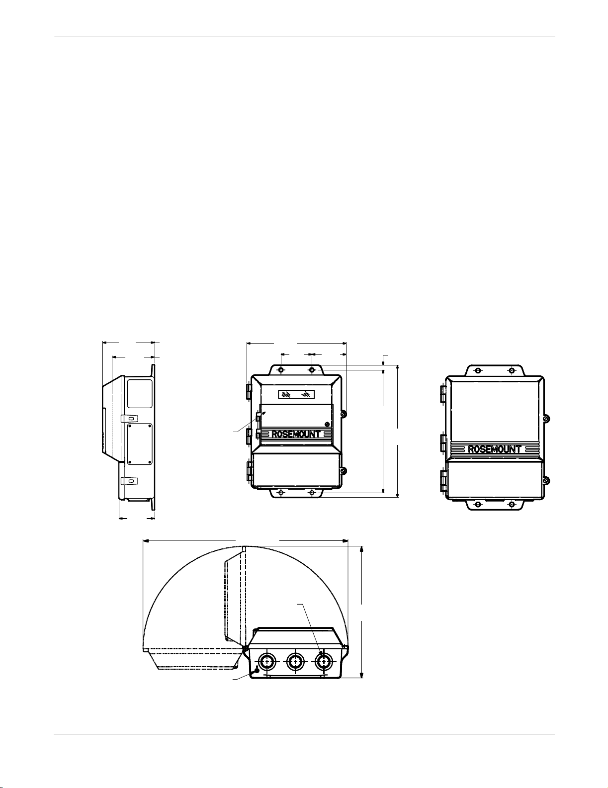
FIGURE 2-1. Model 8712C/U/H Dimensional Drawing
LOI Cover
Standard
Cover
4.31
(109)
3.51
(89)
With LOI Cover
9.01
(229)
2.81
(71)
3.11
(79)
With Standard
Cover
0.44
(11)
NOTE
Dimensions a re in
inches (millimeters).
2.96
(75)
LOI Keypad
Cover
Ground Lug
17.70 (450)
¾–14 NPT
Conduit
Connection
(3 places )
11.15
(283)
12.02
(305)
11.37
(289)
8712-12A01A, 8712B01A, 8712C01A, 8712D01A
2-2

Installation
Environmental Considerations
INSTALLATION PROCEDURES
Mount the Transmitter
To ensure maximum transmitter life, avoid excessive heat and
vibration. Typical problem areas:
• high-vibration lines with integrally mounted transmitters
• warm-climate installations in direct sunlight
• outdoor installations in cold climates.
Remote-mounted transmitters may be installed in the control room to
protect the electronics from the harsh environment and provides easy
access for configuration or service.
Both remotely and integrally mounted Model 8712C/U/H transmitters
require external power and there must be access to a suitable power
source. See Transmitter Input Power on page 2-7.
Model 8712C/U/H installation includes both detailed mechanical and
electrical installation procedures. Before undertaking the installation
instructions outlined below, review the application and related
considerations and requirements. When you understand the system
requirements, proceed with installation.
At a remote site the transmitter may be mounted on a pipe up to two
inches in diameter or against a flat surface. Mounting hardware is
included with remote-mounted transmitters.
Pipe Mounting
To mount the transmitter on a pipe:
Identify Options and Configurations
1. Attach the mounting plate to the pipe using the
mounting hardware.
2. Attach the Model 8712C/U/H to the mounting plate using the
mounting screws.
Surface Mounting
To surface mount the transmitter:
1. Attach the Model 8712C/U/H to the mounting location using the
mounting screws.
The standard application of the Model 8712C/U/H includes a 4–20 mA
output and control of the flowtube coils. Other applications may require
one or more of the following configurations or options:
• Multidrop Communications
• PZR (Positive Zero Return)
• Ultrasonic Control
• Auxiliary Output
• Pulse Output
Additional options may apply. Be sure to identify those options and
configurations that apply to your situation, and keep a list of them
nearby for consideration during the installation and configuration
procedures.
See Safety Messages on page 2-1 for complete warning information.
2-3

Model 8712C/U /H Magnetic Flowmeter Transmitters
Hardware Jumpers/Switches
Failure A l arm Mo de If the Model 8712C/U/H experiences a catastrophic failure in the
Internal/External Analog Power The Model 8712C/U/H 4–20 mA loop may be powered internally
The Model 8712C/U/H electronics board is equipped with
three user-selectable hardware switches (see Figure 2-2). These
switches set the Failure Alarm Mode, Internal/External Analog Power,
and Transmitter Security.
Hardware
Switch
Failure Alarm Mode: HIGH
Internal/External
Analog Power: INTERNAL
Transmitter Security: OFF
Definitions of these switches and their functions are provided below. If
you determine that the settings must be changed, see below.
electronics, the current output can be driven high (23.25 mA) or low
(3.75 mA). The switch is set in the HIGH (23.25 mA) position when it is
shipped from the factory.
or by an external power supply. The internal/external power supply
jumper determines the source of the 4–20 mA loop power.
Transmitters are shipped from the factory with the jumper set
in the INTERNAL position.
Standard Configuration
(as shipped from factory)
The external power option is required for multidrop communications
applications. A 10–30 V dc external supply is required and the jumper
must be reset. For further information on 4–20 mA external power, see
Connect 4–20 mA Loop External Power Source on page 2-10.
Transmitter Secu rity There is a jumper on the Model 8712C/U/H that allows the user to lock
out any configuration changes attempted on the transmitter. No
changes to the configuration are allowed when the jumper is in the ON
position. The flow rate indication and totalizer functions remain active
at all times.
With the jumper in the ON position, you may still access and review
any of the operating parameters and scroll through the available
choices, but no actual data changes are allowed. Transmitter security is
set in the OFF position when shipped from factory.
2-4

Installation
Changing Hardware Switch Settings
In most cases, it is not necessary to change the setting of the hardware
switches. If you need to change the switch settings, complete the steps
outlined below:
NOTE
The hardware switches are located on the solder side of the electronics
board and changing their settings requires opening the electronics
housing. If possible, carry out these procedures away from the plant
environment in order to protect the electronics.
1. Disconnect power to the transmitter.
2. Loosen the housing door screw and open the housing door.
3. Identify the location of each switch or jumper (see Figure 2-2).
4. Switches: Change the setting of the desired switches with a
small screwdriver.
Jumpers: Pull the jumper off of its current setting and connect to
the desired setting.
5. Close the housing door and tighten the housing door screw.
FIGURE 2-2. Model 8712C/U/H Electronics Board and Hardware Switches/Jumpers
Transmitter
Security
Failure
Alarm Mode
Electrical Considerations
8712-013AB
Internal/External
Analog Power
Before making any electrical connections to the Model 8712C/U/H,
consider the following standards and be sure to have the proper power
supply, conduit, and other accessories.
2-5

Model 8712C/U /H Magnetic Flowmeter Transmitters
Conduit Connections
Conduit Installation
Both the flowtube and transmitter junction boxes have ports for
¾–inch NPT conduit connections. If some of these ports are not being
used, conduit seals will need to be installed. In some cases, conduits
may also require drainage if there is a possibility of moisture build-up
in the line.
A dedicated conduit line is required for the coil drive and electrode
cables that connect the flowtube to the transmitter (see Figure 2-4 on
page 2-7). Separate conduits are not necessary for the two cables, but a
dedicated conduit line between each transmitter and flowtube is
required. Instructions for installation of the conduit begin on page 2-6.
If ¾-inch NPT conduit is not installed between the flowtube and
transmitter, install the conduit.
NOTE
A dedicated conduit line is required between each transmitter and
flowtube. See page 2-7 for further information on conduit layout
and design.
1. Install the conduit for operating options used in your application.
2. Connect the ¾-inch NPT conduit to the transmitter and to the
flowtube in accordance with local or plant electrical codes.
3. Seal unused ports to prevent moisture or other contamination
from entering the junction box.
NOTE
Do not overtighten metal plugs used to seal wiring compartment ports;
overtightening can damage the housing.
Conduit Cabl es Run the appropriate size cable through the conduit connections in your
magnetic flowmeter system.
1. Run the power cable from the power source to the transmitter.
2. Run the coil drive and electrode cables between the flowmeter
and transmitter.
3. Run any additional cables required for your application and the
applicable options.
Prepare the ends of the coil drive and electrode cables as shown in
Figure 2-3. Limit the unshielded wire length to 1-inch on both the
electrode and coil drive cables.
NOTE
Excessive lead length can cause unwanted transmitter noise.
2-6
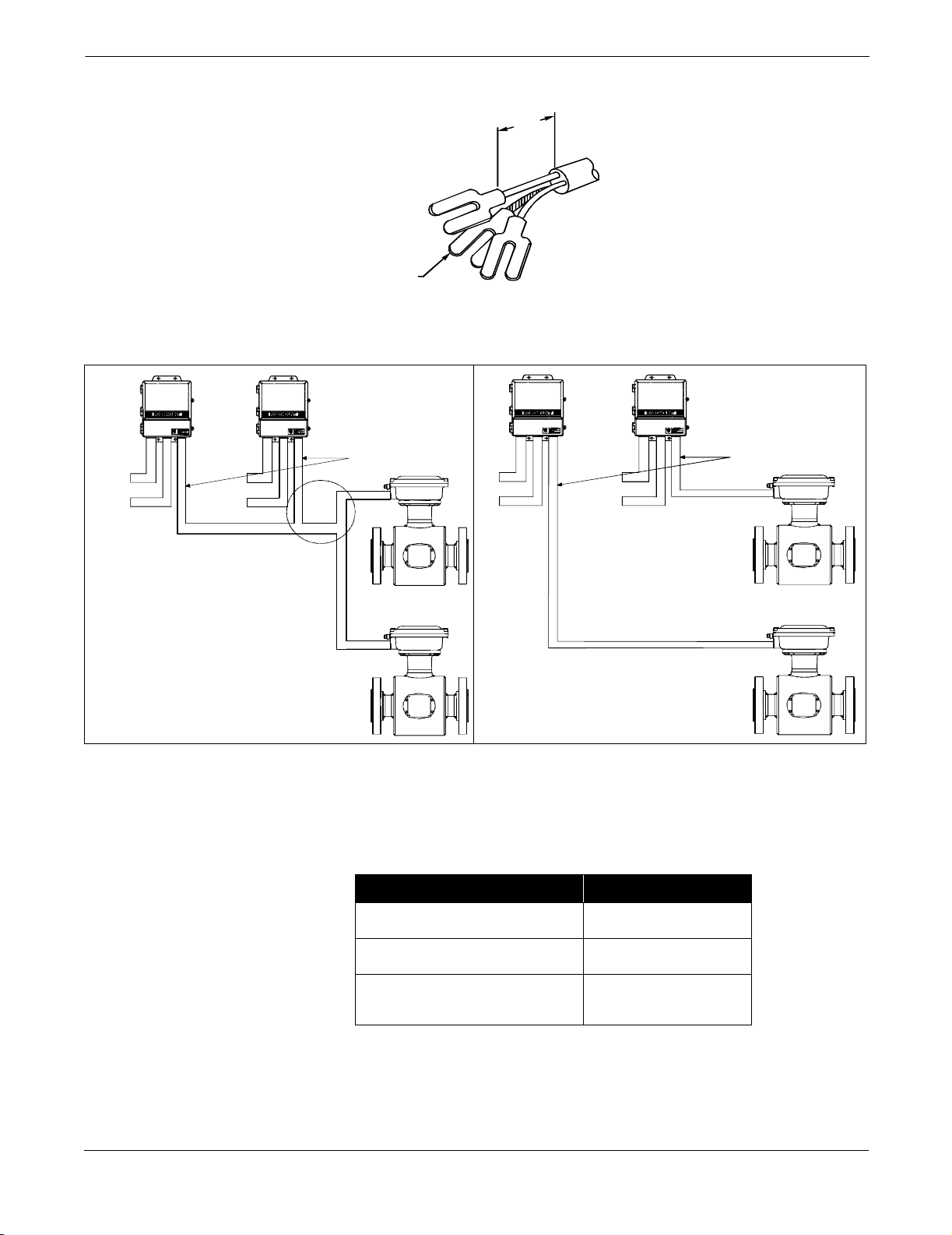
FIGURE 2-3. Cable Preparation
FIGURE 2-4. Conduit Preparation
Cable Shield
1.0
(25)
NOTE
Dimensions are in
inches (millim eters).
Installation
8712-0041A
Powe r
Outputs
Powe r
Outputs
Coil Drive and
Electrode Cables
Powe r
Outputs
Powe r
Outputs
Coil Dri ve a nd
Electrode Cables
Incorrect Correct
Conduit Cables Cables to be used in the conduit for coil drive and electrode connections
must meet the standards shown in Table 2-1.
TABLE 2-1. Recommended Cable Specifications
Tran smitt er Inp ut Pow er
Description Rosemo unt Part Nu mber
Signal Cable (20 AWG)
Belden 8762, Alpha 2411 equivalen t
Coll Drive C able (14 AWG)
Belden 8720, Alpha 2442 equivalen t
Combinat ion Signa l and Coil
DriveCable(18AWG)
Belden 9368 equivale nt
(1)
(1) Comb ination signa l and co il dr ive cable is n ot reco mmended for
high-s ignal magmete r s ystem. For remote mou nt in stallations,
combin ation signal and c oil dr ive cable s hould b e limi ted to les s
than 100 ft (30 m).
08712-0 061-0001
08712-0 060-0001
08712-0 750-0001
8705-0000A01A, 0000A01B
2-7

Model 8712C/U /H Magnetic Flowmeter Transmitters
Transmitter Input Power The Model 8712C/U/H transmitter is designed to be powered by 10–30 V
dc, 115 V ac, or 230 V ac. The seventh and eighth digits in the transmitter
model number designates the appropriate power supply requirement.
Supply Wire Temperature Rating
Use 12 to 18 AWG wire. For connections in ambient temperatures
exceeding 60 °C (140 °F), use wire rated to at least 90 °C (194 °F).
Disconnects
Connect the device through an external disconnect or circuit breaker.
Clearly label the disconnect or circuit breaker and locate it near the
transmitter.
Requirements for 115 V ac or 230 V ac Power Supply
Wire the transmitter according to local electrical requirements for
115 V ac or 230 V ac. In addition, follow the supply wire and disconnect
requirements below:
Requirements for 10–30 V dc Power Su pply
Units powered with 10–30 V dc may draw up to 2 amps of current. As a
result, the input power wire must meet certain gauge requirements.
Table 2-2 and Table 2-3 show the maximum wire length for
corresponding supply voltages, wire gauges, and wire type.
Figure 2-5 shows the surge current for each corresponding supply
voltage. For combinations not shown, you can calculate the maximum
distance given the surge current, the voltage of the source, and the
minimum start-up voltage of the transmitter, 10 V dc, using the
following equation:
MaximumRe sis cetan
SupplyVoltage 10Vdc–
-------------------------------------------------------------------=
SurgeCurrent
Use Table 2-2 and Table 2-3 to determine the maximum wire length
allowable for your power supply and maximum resistance.
TABLE 2-2. Length of Annealed Copper (Cu) Wires
Types of
Power Supply Wires
Wire Gauge
20 10.15 (33.29) 1,230 (375) 625 (191) 365 (111) 115 (35)
18 6.385 (20.94) 1,955 (596) 990 (302) 585 (178) 185 (56)
16 4.016 (13.17) 3,110 (948) 1,580 (482) 930 (283) 295 (90)
14 2.525(8.28) 4,950 (1,509) 2,515 (767) 1,485(453) 475 (145)
12 1.588(5.21) 7,870 (2,399) 3,995(1,218) 2,360(719) 755 (230)
10 0.999(3.28) 12,510(3,813) 6,355(1,937) 3,750(1,143) 1,200(366)
Types of
Power Supply Wires
Wire Gauge
18 6.640 (21.78) 1,880 (573) 955 (291) 565 (172) 180 (55)
16 4.176 (13.70) 2,990 (911) 1,520 (463) 895 (273) 285 (87)
14 2.626(8.61) 4,760 (1,451) 2,415 (736) 1,425(434) 455 (139)
12 1.652(5.42) 7,565 (2,306) 3,840(1,170) 2,270(692) 725 (221)
10 1.039 (3.41) 12,030 (3,667) 6,110 (1862) 3,605 (1,099) 1,155 (352)
Annealed Cu
milliohms/ft
(milliohms/m)
Hand-drawn Cu
milliohms/ft
(milliohms/m)
Maximum Length of the Wire for Each Corresponding Power Supply Source
30 V Supply
ft (m)
24 V Supply
ft (m)
20 V Supply
ft (m)
TABLE 2-3. Length of Hand-drawn Copper (Cu) Wires
Maximum Length of the Wire for Each Corresponding Power Supply Source
30 V Supply
ft (m)
24 V Supply
ft (m)
20 V Supply
ft (m)
14 V Supply
ft (m)
14 V Supply
ft (m)
2-8
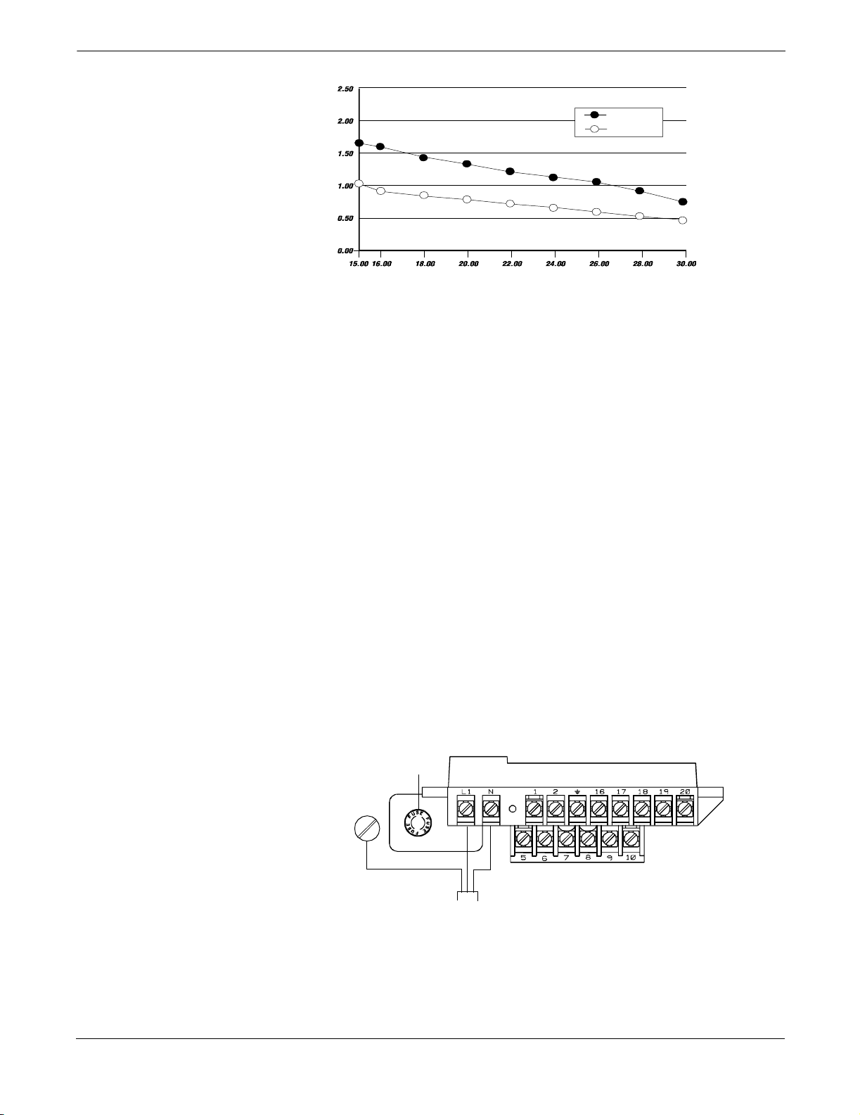
FIGURE 2-5. Supply Current versus Input Voltage
S
l
C
(A
)
mperes
urrent
y
upp
Installation
Surge
Nominal
OPTIONS, CONSIDERATIONS, AND PROCEDURES
Connect Transmitter Power
Input Voltage (Volts)
If your application of the Model 8712C/U/H includes the use of options
such as multidrop communications, positive zero return (PZR),
auxiliary output control, or pulse output, certain requirements may
apply in addition to those previously listed. Be prepared to meet these
requirements before attempting to install and operate the
Model 8712C/U/H.
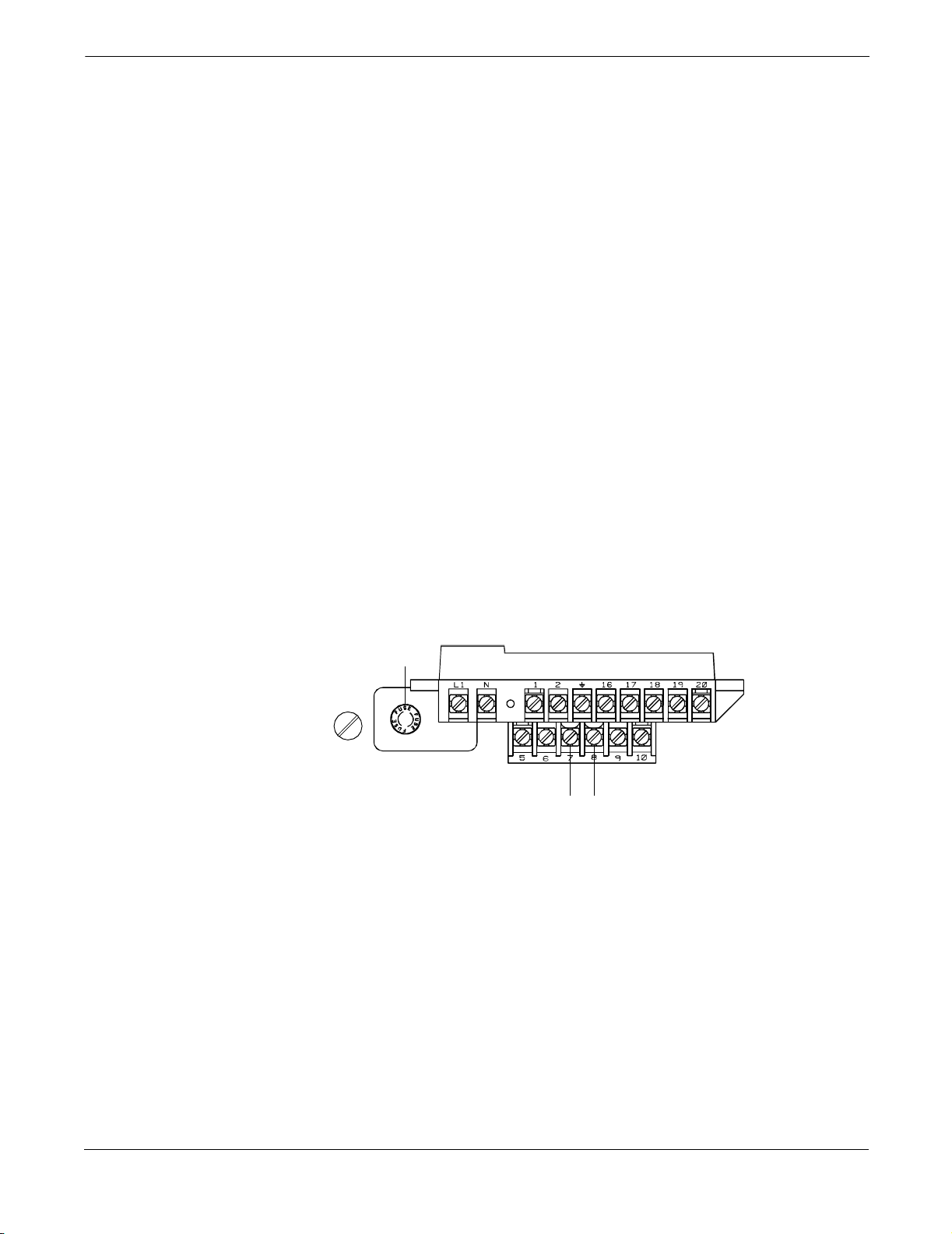
To connect power to the transmitter, complete the following steps.
1. Ensure that the power source and connecting cable meet the
requirements outlined in Transmitter Input Power on page 2-7.
2. Turn off the power source.
3. Open the power terminal cover.
4. Run the power cable through the conduit to the transmitter.
5. Loosen the terminal guard for terminals L1 and N.
6. Connect the power cable leads as follows:
• Connect ac Neutral/dc- to terminal N.
• Connect ac Line/dc+ to terminal L1.
• Connect ac Ground/dc Ground to the ground screw.
8712-0388A
FIGURE 2-6. Transmitter
Po werConnections
Fuse
ac Line or dc+
ac Ground or
dc Ground
ac Neutral or dc–
Transmitter
Power Cable
8712-8712E01B
2-9
Model 8712C/U /H Magnetic Flowmeter Transmitters
Connect 4–20 mA Loop External Power Source
The 4–20 mA output loop provides the process variable output from the
transmitter. Its signal may be powered internally or externally. The
default position of the internal/external analog power jumper is in the
internal position. The user-selectable power supply jumper is located on
the electronics board.
Internal
The 4–20 mA analog power loop may be powered from the transmitter
itself. Resistance in the loop must be 1,000 ohms or less. If a HART
Communicator or control system will be used, it must be connected
across a minimum of 250 ohms resistance in the loop.
External
HART multidrop installations require a 10–30 V dc external analog
power source (see Multidrop Communications on page 4-18). If a
HART Communicator or control system is to be used, it must be
connected across a minimum of 250 ohms resistance in the loop.
To connect external power to the 4–20 mA loop, complete the
following steps.
1. Ensure that the power source and connecting cable meet the
requirements outlined above and in Electrical Considerations
on page 2-5.
2. Turn off the transmitter and analog power sources.
3. Run the power cable into the transmitter.
4. Connect –dc to Terminal 8.
5. Connect +dc to Terminal 7.
FIGURE 2-7. 4–20 mA Loop PowerConnections
Fuse
–4–20 mA power+4–20 mA power
8712-8712E01B
2-10
Installation
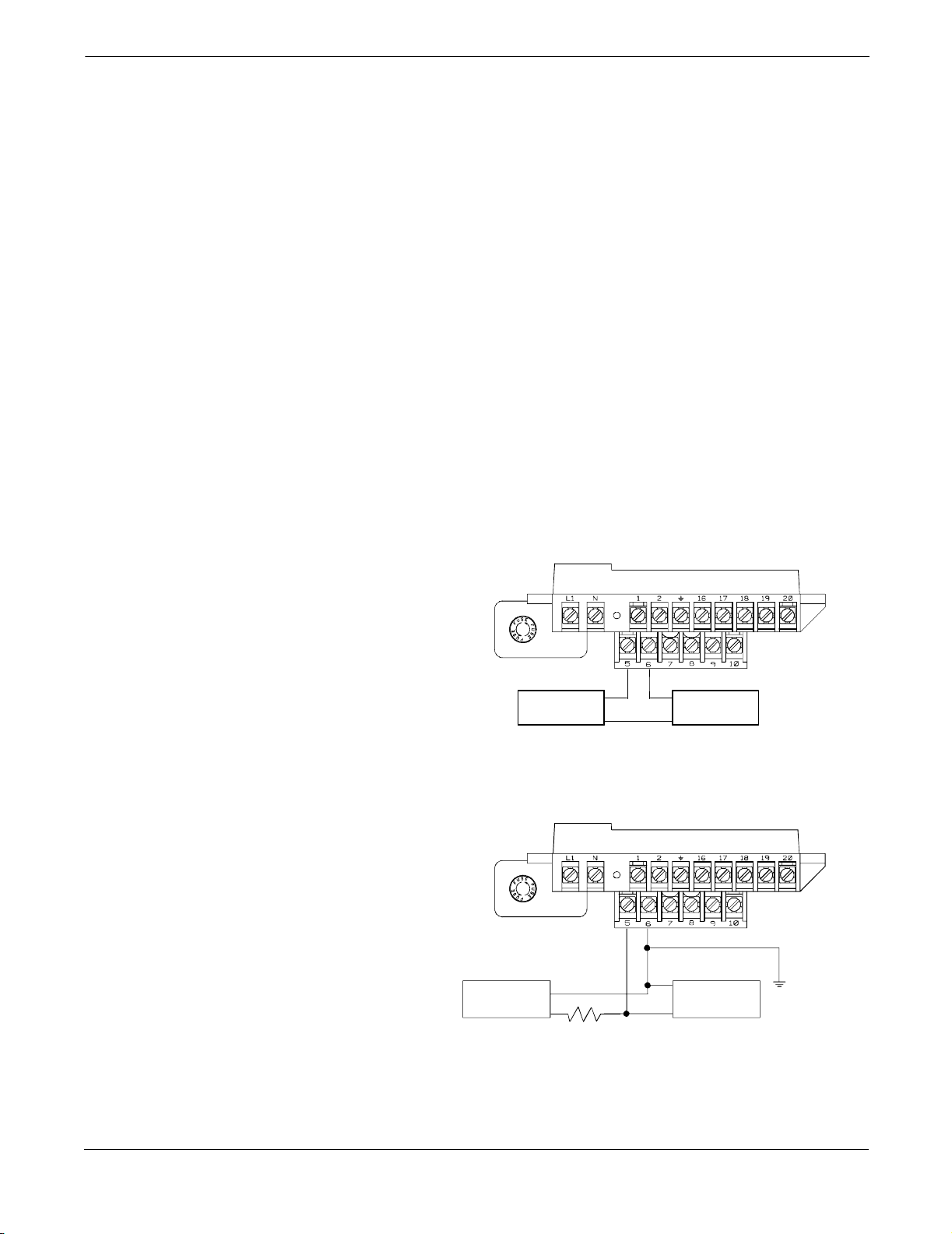
Connect Pulse Output Power Source
The pulse output function provides an optically isolated switch-closure
frequency output signal that is proportional to the flow through the
flowtube. The signal is typically used in conjunction with an external
totalizer or control system. The following requirements apply:
Supply Voltage: 5 to 24 V dc
Load Resistance: 1,000 to 100 k ohms (typical
Pulse Duration: 0.5 to 100 m/sec (adjustable)
Maximum Power: 5.75 watts
Switch Closure: transistor, open collector, PNP
The pulse output option requires an external power source. Complete
the following steps to connect an external power supply.
1. Ensure that the power source and connecting cable meet the
2. Turn off the transmitter and pulse output power sources.
3. Run the power cable to the transmitter.
4. Connect –dc to terminal 6.
5. Connect +dc to terminal 5.
Refer to Figure 2-8 and Figure 2-9.
FIGURE 2-8. Electromechanical Totalizer/Counter
' 5 k)
requirements outlined above.
FIGURE 2-9. Electronic Totalizer/Counter without Integral Power Supply
5–24 V dc
Power Supply
Electro-
mechanical
Counter
–
+
1k to 100 k
Typical ' 5k
+ –
––
+ +
+
–
–
+
5–24 V dc
Power
Supply
Electronic
Counter
8712-8712|11A
8712-8712|11B
2-11
Model 8712C/U /H Magnetic Flowmeter Transmitters
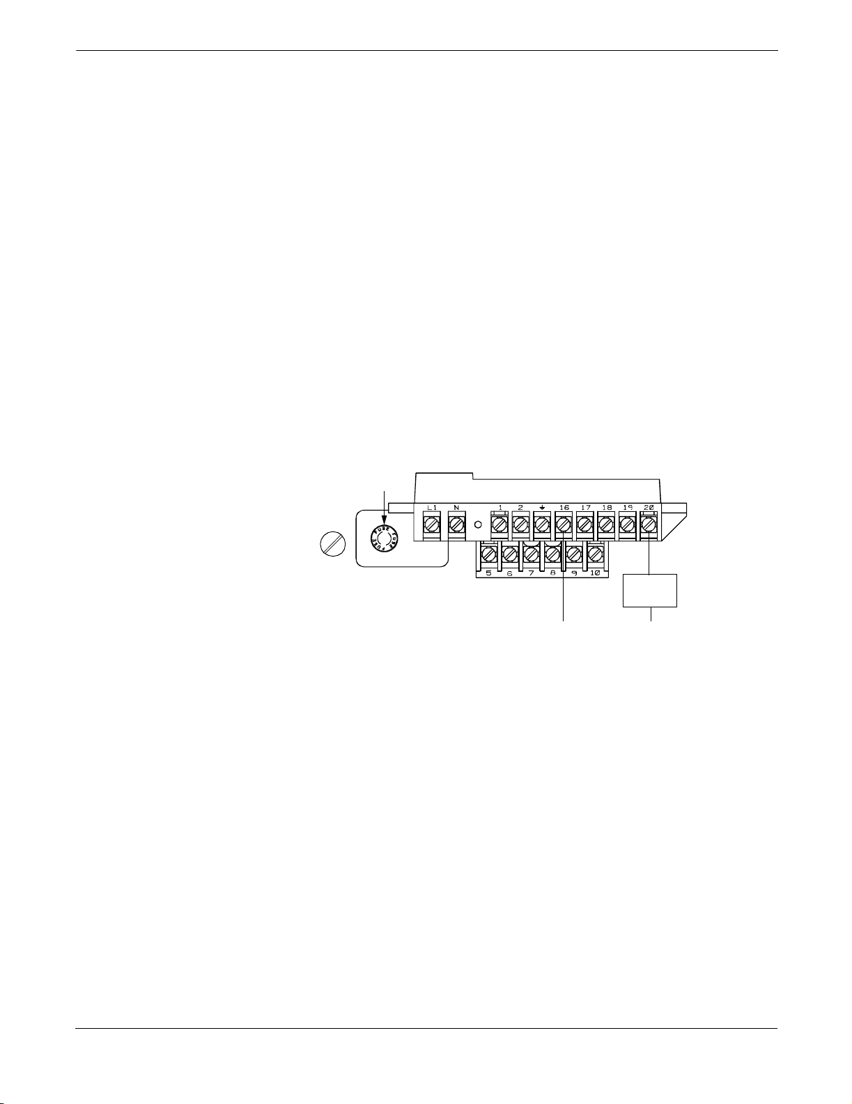
Connect Auxiliary
Output Control
The auxiliary output control function allows you to externally signal a
zero flow or reverse flow condition. The following requirements apply:
Supply Voltage: 5 to 24 V dc
Maximum Power: 5.75 watts
Switch Closure: transistor, open collector, PNP
If you are using auxiliary output control, you need to connect the power
source and control relay to the transmitter. To connect external power
for auxiliary output control, complete the following steps:
1. Ensure that the power source and connecting cable meet the
requirements outlined above.
2. Turn off the transmitter and auxiliary power sources.
3. Run the power cable to the transmitter.
4. Connect –dc to terminal 20.
5. Connect +dc to terminal 16.
FIGURE 2-10. Auxiliary Output Control Power Connections
Fuse
Control
Relay
dc–dc+
8712-8712E01B
2-12
Installation
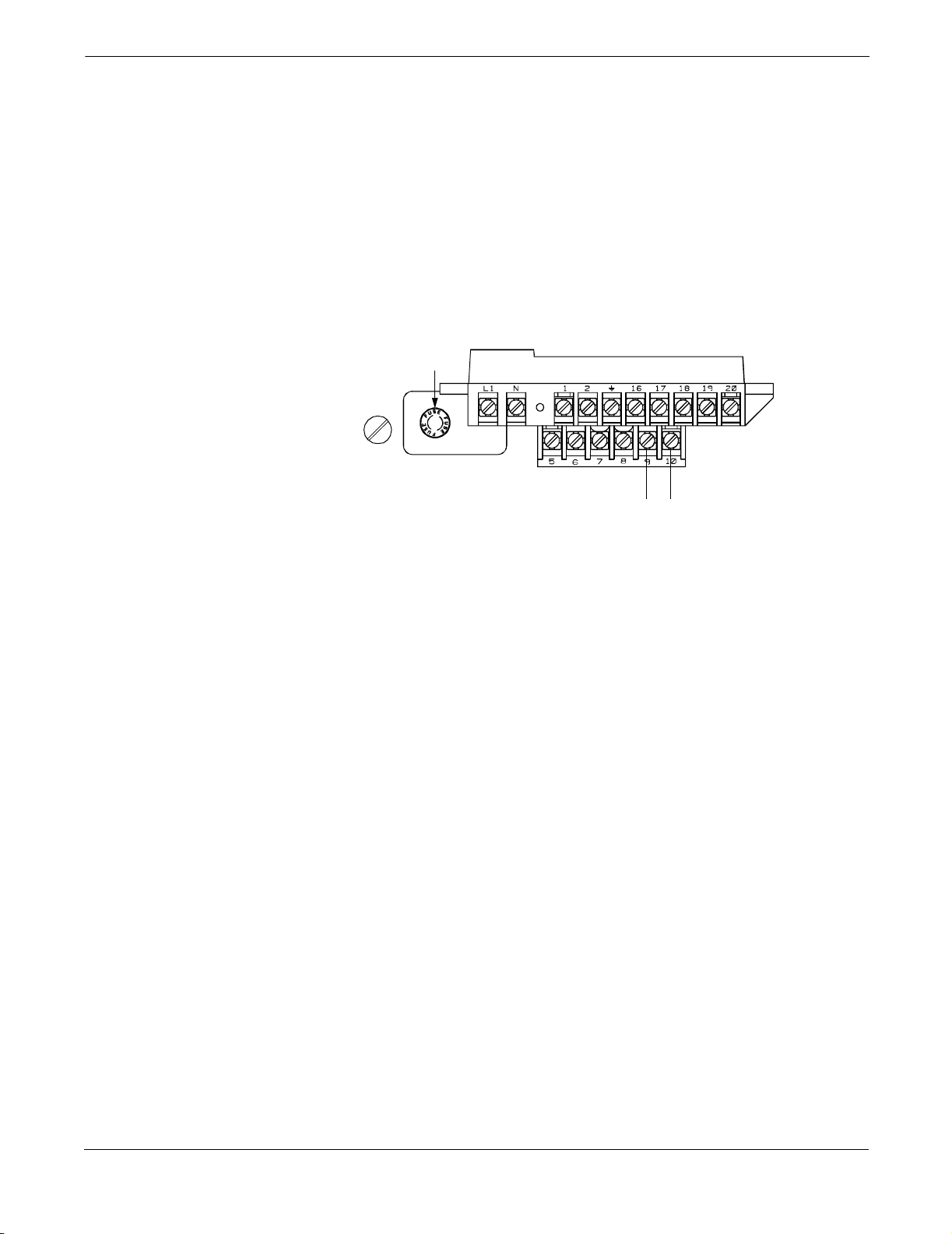
Connect Positive Zero Return (PZR) PowerSource
The PZR function allows the transmitter output to be forced to a zero
flow rate signal. While in this state, the transmitter will not react to
input changes. A zero flow rate signal appears until the PZR signal is
removed.
PZR is activated by an isolated external switch closure connecting
transmitter terminals 9 and 10.
To connect the PZR, complete the following steps.
FIGURE 2-11. PositiveZero Return Connections
1. Run the switch cable to the transmitter.
2. Connect switch leads to Terminal 9 and 10.
Fuse
PZR Switch LeadPZR Switch Lead
8712-8712E01B
2-13
Model 8712C/U /H Magnetic Flowmeter Transmitters
FLOWTUBE CONNECTIONS
Rosemount Flowtubes
Flowtubes of Other Manufacturers
This section covers the steps required to physically install the
transmitter including wiring and calibration.
To connect the transmitter to a Rosemount flowtube, refer to the
appropriate wiring diagram in Appendix B. The calibration procedure
listed below is not required for use with Rosemount flowtubes.
Before connecting another manufacturer’s flowtube to the Model 8712U
transmitter, it is necessary to perform the following functions.
1. Turn off the ac power to the flowtube and transmitter. Failure to
do so could result in electrical shock or damage to the transmitter.
2. Verify that the coil drive cables between the flowtube and the
transmitter are not connected to any other equipment.
3. Label the coil drive cables and electrode cables for connection to
the transmitter.
4. Disconnect the wires from the existing transmitter.
5. Remove the existing transmitter. Mount the new transmitter. See
Mount the Transmitter on page 2-3.
6. Verify that the flowtube coil is configured for series connection.
Other manufacturers flowtubes may be wired in either a
series or parallel circuit. All Rosemount magnetic flowtubes are
wired in a series circuit.
7. Verify that the flowtube is in good working condition. Use the
manufacturer’s recommended test procedure for verification of
flowtube condition. Perform the basic checks:
• Check the coils for shorts or open circuits.
• Check the flowtube liner for wear or damage.
• Check the electrodes for shorts, leaks, or damage.
8. Determine the coil resistance value of the flowtube. Record this
value for the Universal Auto Trim function.
9. Connect the flowtube to the transmitter in accordance with
reference wiring diagrams. See Appendix B Wiring Diagrams
for specific drawings.
2-14
This is a pulsed dc magnetic flowmeter. Do not
connect ac power to the flowtube or to terminals
1 and 2 of the transmitter, or replacement of the
electronicsboard will be necessary.
10. Connect and verify all connections between the flowtube and the
transmitter, then apply power to the transmitter.
11. Perform the Universal Auto Trim function as explained
on page 4-5.
See Safety Messages on page 2-1 for complete warning information.

Installation
APPLYING POWER
SOFTWARE INSTALLATION
All magnetic flowmeter system connections must be completed before
power is applied to the system. Check the flowmeter connections
between flowmeter and flowtube to be sure they are correct. Check the
connections between the power supply and the system to be sure they
are correct. Apply power to the transmitter.
Once the magnetic flowmeter system is installed and communication is
established, the transmitter should be configured for basic functions to
complete the installation. You may perform these functions with the
LOI (Section 3 Local Operator Interface) or HART Communicator
(Appendix A HART Communicator). Specific instructions regarding
these functions are provided in Section 4 Device Software
Functions.
Basic software values must be set to complete installation:
• tube calibration number
•tube size
•units
• analog output range
• in-process calibration (Model 8712U and other manufacturers’
flowtubes only)
If your application of the magnetic flowmeter system involves more
advanced functions such as multidrop or pulse output, additional
configuration steps may be required to enable full functionality. See
Section 4 Device Software Functions.
See Safety Messages on page 2-1 for complete warning information.
2-15

Model 8712C/U /H Magnetic Flowmeter Transmitters
Installation Check
and Guide
Use this guide to check new installations of Rosemount magnetic
flowmeter systems that appear to malfunction.
Before You Begin
Be sure that power to your system is off before beginning these checks.
T r ansmitter
1. Check that the correct flowtube calibration number entered in the
software. The calibration number is listed on the flowtube
nameplate.
2. Check that the correct flowtube line size is entered in the
software. The line size value is listed on the flowtube nameplate.
3. Check that the analog range of the transmitter matches the
analog range in the control system.
4. Check that the forced analog output of the transmitter produces
the correct output at the control system.
Flowtube
1. For horizontal flow installations, ensure that the electrodes
remain covered by process fluid.
For vertical or inclined installations, ensure that the process
fluid is flowing up into the flowtube to keep the electrodes covered
by process fluid.
2. Ensure that the grounding straps on the flowtube are connected
to grounding rings, lining protectors, or the adjacent pipe flanges.
Improper grounding will cause erratic operation of the system.
Wiring
1. The signal wire and coil drive wire must be twisted shielded
cable. Rosemount Inc. recommends 20 AWG twisted shielded
cable for the electrodes and 14 AWG twisted shielded cable for
the coils.
2. The cable shield must be connected at both ends of the electrode
and coil drive cables. Connection of the shield at both ends is
absolutely necessary for proper operation.
3. The signal and coil drive wires must have their own cables.
4. The single conduit that houses both the signal and coil drive
cables should not contain any other wires.
Process Fluid
1. The process fluid conductivity should be 5 microhms per
centimeter minimum.
2. The process fluid must be free of air and gasses.
3. The flowtube should be full of process fluid.
2-16
Installation
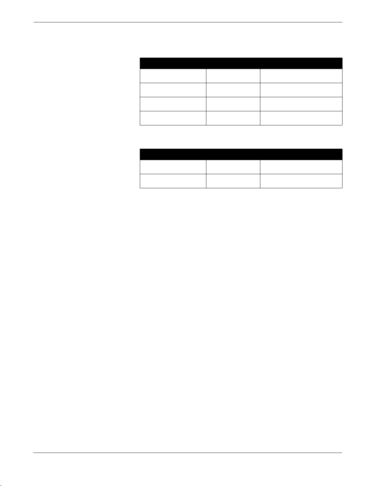
Flowtube Resistance
1. Check the following loops with power off and wires disconnected.
Record the readings in the open position of the table.
Loop Terminals Reading Parameters
1 to 2 This coil check should read between
2and18
GND to 1 This coil to ground check should be
open on highest range.
1 to 18 This coil to electrodecheck should be
open on highest range.
1 to 19 This coil to electrodecheck should be
open on highest range.
V.
2. Check with the flowtube filled with a process fluid. Use the initial
reading because the value will increase with time.
Loop Terminals Reading Parameters
17 to 18 This shield to electrode reading
shouldbe100k
17 to 19 This shield to electrode reading
shouldbe100k
V or greater.
V or greater.
If performing these checks and making any necessary adjustments to
your system does not solve the problem, or for specific instructions on
making these adjustments, see Table 5-1 on page 5-2 and Table 5-2 on
page 5-3 or contact your Rosemount service representative.
2-17

Model 8712C/U /H Magnetic Flowmeter Transmitters
2-18
Section
3 Local Operator Interface
LOCAL OPERATOR INTERFACE
BASIC FEATURES
The optional Local Operator Interface (LOI) provides an operator
communications center for the Model 8712C/U/H. By using the LOI, the
operator can access any transmitter function for changing configuration
parameter settings, checking totalized values, or other functions. The
LOI is integral to the transmitter housing.
The basic features of the LOI include display control, totalizer, data
entry, and transmitter parameters. These features provide control of all
transmitter functions.
Display Control Keys
The display control keys provide control over the variable displayed on
the LOI screen. Push FLOW RATE to display the process variable, or
push T OTALIZE to display the totalized value.
Totalizer Keys
The totalizer keys enable you to start, stop, read, and reset
the totalizer.
Data Entry K eys
The data entry keys enable you to move the display cursor,
incrementally increase the value, or enter the selected value.
Transmitter Parameter Keys
The transmitter parameter keys provide direct access to the most
common transmitter parameters and stepped access to the advanced
functions of the Model 8712C/U/H through the AUX. FUNCTION key.
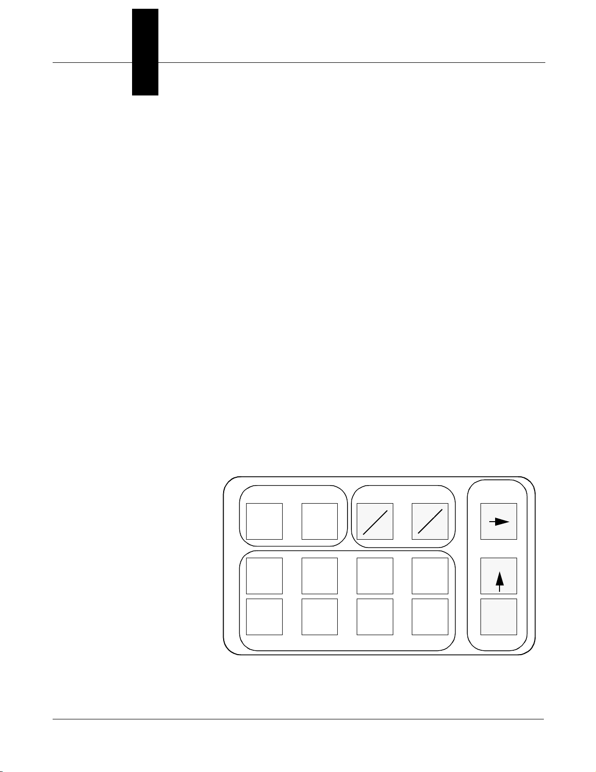
FIGURE 3-1. Local Operator Interface Keypad
DISPLAY CONTROL TOTALIZER
FLOW
RATE
TUBE
CAL
NO.
ANALOG
OUTPUT
RANGE
TOTALIZE
TUBE
SIZE
PULSE
OUTPUT
SCALING
START
STOP
UNITS
DAMPING XMTR INFO
READ
FUNCTION
TRANSM ITTE RPARAMET ERS
RESET
AUX.
DAT A
ENTRY
SHIFT
INCR.
ENTER
3-1

Rosemount Model 8712C/U/H Magnetic Flowmeter Transmitters
Data Entry
Selecting Options
LOI EXAMPLES
The LOI keypad does not have numerical keys. Numerical data are
entered by the following procedure.
1. Access the appropriate function.
2. Use SHIFT to highlight the digit you want to enter or change.
3. Use INCR. to change the highlighted value. For numerical data,
INCR. toggle through the digits 0–9, decimal point, dash, and
blank. For alphabetical data, toggle through the letters of the
alphabet A–Z, digits 0–9, and the symbols &, +, -, *, /, $, @,%, and
the blank space. (INCR. is also used to toggle through pre-
determined choices that do not require data entry.)
4. Use SHIFT to highlight other digits you want to change and
change them.
5. Press ENTER.
To select pre-defined software options on the LOI, use the
following procedure:
1. Access the appropriate option.
2. Use SHIFT or INCR. to toggle between the applicable choices.
3. Press ENTER when the desired choice is displayed in the screen.
Use the TRANSMITTER PARAMETER keys shown in Figure 3-1 to
change the parameters, which are set in one of two ways, table values or
select values.
Table Value Example
Select Value Example
Table Values: parameters such as units, that are available from a
predefined list
Select Values: parameters that consist of a user-created number or
character string, such as calibration number; values are
entered one character at a time using the data
entry keys
Setting the TUBE SIZE:
1. Press TUBE SIZE.
2. Press SHIFT or INCR. to increase (incrementally) the tube size to
the next value.
3. When you reach the desired size, press ENTER .
4. Set the loop to manual if necessary, and press ENTER again.
After a moment, the LCD will display the new tube size and the
maximum flow rate.
Changing the ANALOG OUTPUT RANGE:
1. Press ANALOG OUTPUT RANGE.
2. Press SHIFT to position the cursor.
3. Press INCR. to set the number.
4. Repeat steps 2 and 3 until desired number is displayed.
5. Press ENTER.
After a moment, the LCD will display the new tube size and the
maximum flow rate.
3-2
 Loading...