

Page 1

00825-0400-4444, Rev. AA
Rosemount® 8700M
Magnetic Flowmeter Platform
with Modbus® RS-485 Protocol
Quick Start Guide
August 2015
Page 2

Quick Start Guide
August 2015
NOTICE
This document provides basic installation guidelines for the Rosemount 8700M Magnetic
Flowmeter Platform with Modbus RS-485 Protocol. For information about installing,
configuring, maintaining, or troubleshooting this product, refer to Reference Manual
00809-0400-4444. The reference manual—as well as this quick start guide—are available online
at www.rosemount.com.
Failure to follow these installation guidelines could result in death or serious injury.
Installation and servicing instructions are for use by qualified personnel only. Do not perform
any servicing other than that contained in the operating instructions, unless qualified.
Verify the installation is done safely and is consistent with the operating environment.
If installed in explosive atmospheres (hazardous areas, classified areas, or an “Ex” environment),
it must be assured that the device certification and installation techniques are suitable for that
particular environment.
Explosion hazard—Do not disconnect equipment when a flammable or combustible atmosphere
is present.
To prevent ignition of flammable or combustible atmospheres, disconnect power before
servicing circuits.
Do not connect a Rosemount 8732EM Transmitter to a non-Rosemount sensor that is located in
an explosive atmosphere.
Substitution of components may impair Intrinsic Safety.
Follow national, local, and plant standards to properly earth ground the transmitter and sensor.
The earth ground must be separate from the process reference ground.
Rosemount Magnetic Flowmeters ordered with non-standard paint options or non-metallic
labels may be subject to electrostatic discharge. To avoid electrostatic charge build-up, do not
rub the flowmeter with a dry cloth or clean with solvents.
NOTICE
The sensor liner is vulnerable to handling damage. Never place anything through the sensor for
the purpose of lifting or gaining leverage. Liner damage may render the sensor inoperable.
Metallic or spiral-wound gaskets should not be used as they will damage the liner face of the
sensor. If spiral wound or metallic gaskets are required for the application, lining protectors
must be used. If frequent removal is anticipated, take precautions to protect the liner ends.
Short spool pieces attached to the sensor ends are often used for protection.
Correct flange bolt tightening is crucial for proper sensor operation and life. All bolts must be
tightened in the proper sequence to the specified torque specifications. Failure to observe
these instructions could result in severe damage to the sensor lining and possible sensor
replacement.
In cases where high voltage/high current are present near the meter installation, ensure proper
protection methods are followed to prevent stray voltage/current from passing through the
meter. Failure to adequately protect the meter could result in damage to the transmitter and
lead to meter failure.
Completely remove all electrical connections from both sensor and transmitter prior to welding
on the pipe. For maximum protection of the sensor, consider removing it from the pipeline.
Contents
Transmitter installation . . . . . .page 3
Handling and lifting . . . . . . . . . page 5
Mounting . . . . . . . . . . . . . . . . . . page 6
Sensor installation . . . . . . . . . . . page 9
2
Process reference connection page 15
Wiring the transmitter . . . . . .page 18
Modbus configuration . . . . . . page 28
Product Certifications . . . . . . page 36
Page 3
August 2015
Quick Start Guide
Step 1: Transmitter installation
Installation of the Rosemount Magnetic Flowmeter includes both detailed
mechanical and electrical installation procedures.
Before installing the Rosemount 8732EM Magnetic Flowmeter Transmitter, there
are several pre-installation steps that should be completed to make the
installation process easier:
Identify the options and configurations that apply to your application
Set the hardware switches if necessary
Consider mechanical, electrical, and environmental requirements
1.1 Identify options and configurations
The typical installation of the 8732EM includes a device power connection, a
Modbus RS-485 output connection, and sensor coil and electrode connections.
Other applications may require one or more of the following configurations or
options:
Pulse Output
Discrete Input/Discrete Output
Hardware switches
The 8732EM electronics stack is equipped with user-selectable hardware
switches. These switches set the Internal/External Pulse Power and Transmitter
Security. The factory default settings for these switches is as follows:
Table 1. Hardware Switch Default Settings
Hardware switch Default setting
Internal/External Pulse Power
Transmitter Security
External
Off
In most cases, it will not be necessary to change the hardware switch settings. If
the settings need to be changed, follow the steps outlined under “Changing
hardware switch settings” in Reference Manual 00809-0400-4444.
Note
To prevent switch damage, use a non-metallic tool to move switch positions.
Be sure to identify any additional options and configurations that apply to the
installation. Keep a list of these options for consideration during the installation
and configuration procedures.
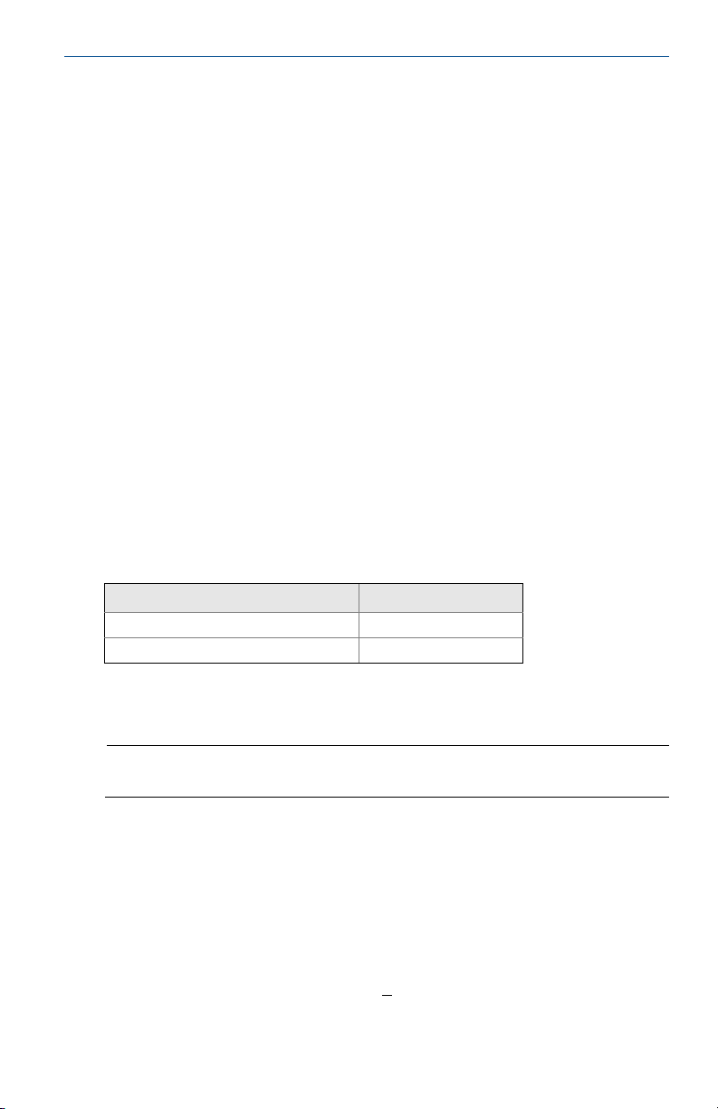
1.2 Mechanical considerations
The mounting site for the Rosemount 8732EM transmitter should provide
enough room for secure mounting, easy access to conduit entries, full opening of
the transmitter covers, and easy readability of the LOI screen, if equipped.
For remote mount transmitter (8732EMR
provided for use on a 2-inch pipe or a flat surface (see Figure 1).
xxx) installations, a mounting bracket is
3
Page 4
Quick Start Guide
>@
Note
If the Rosemount 8732EM is mounted separately from the sensor, it may not be subject to
limitations that might apply to the sensor.
Rotate integral mount transmitter housing
The transmitter housing can be rotated on the sensor in 90-degree increments by
removing the four mounting screws on the bottom of the housing. Do not rotate
the housing more than 180 degrees in any one direction. Prior to tightening, be
sure the mating surfaces are clean, the O-ring is seated in the groove, and there is
no gap between the housing and the sensor.
Figure 1. Rosemount 8732EM Dimensional Drawing
August 2015
Note
Conduit entries are 1/2- in. NPT or M20 connections. If an alternate thread connection is
required, thread adapters must be used.
1.3 Electrical considerations
Before making any electrical connections to the Rosemount 8732EM, consider
national, local, and plant electrical installation requirements. Be sure to have the
proper power supply, conduit, and other accessories necessary to comply with
these standards.
Both remotely and integrally mounted Rosemount 8732EM transmitters require
external power, so there must be access to a suitable power source.
4
Page 5

August 2015
Quick Start Guide
Table 2. Electrical Data
Rosemount 8732EM Flow Transmitter
Power input 90–250VAC, 0.45A, 40VA
Pulsed circuit Internally powered (Active): Outputs up to 12VDC, 12.1mA, 73mW
Modbus output circuit Internally powered (Active): Outputs up to 3.3VDC, 100mA, 100mW
Termination resistors Typically 120 ohms. Refer to the MODBUS over Serial Line Specification &
Um 250V
Coil excitation output 500mA, 40V max, 9W max
Rosemount 8705-M and 8711-M/L Sensor
Coil excitation input 500mA, 40V max, 20W max
Electrode circuit 5V, 200uA, 1mW
1. Provided by the transmitter
12–42VDC, 1.2A, 15W
Externally powered (Passive): Input up to 28VDC, 100mA, 1W
Implementation Guide (http://www.modbus.org) for more details.
(1)
1.4 Environmental considerations
To ensure maximum transmitter life, avoid extreme temperatures and excessive
vibration. Typical problem areas include the following:
High-vibration lines with integrally mounted transmitters.
Tropical/desert installations in direct sunlight.
Outdoor installations in arctic climates.
Remote-mounted transmitters may be installed in the control room to protect
the electronics from the harsh environment and to provide easy access for
configuration or service.
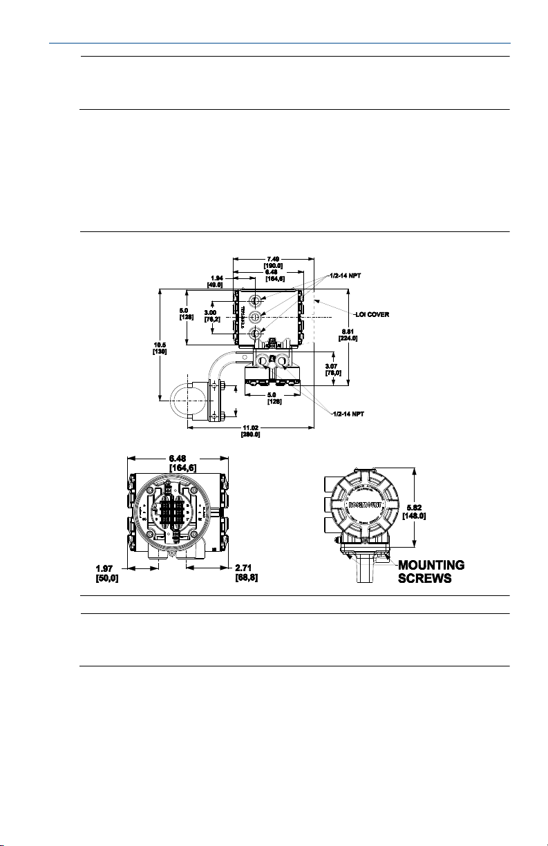
Step 2: Handling and lifting
Handle all parts carefully to prevent damage. Whenever possible, transport
the system to the installation site in the original shipping container.
PTFE-lined sensors are shipped with end covers that protect it from both
mechanical damage and normal unrestrained distortion. Remove the end
covers just before installation.
Keep the shipping plugs in the conduit connections until you are ready to
connect and seal them.
The sensor should be supported by the pipeline. Pipe supports are
recommended on both the inlet and outlet sides of the sensor pipeline. There
should be no additional support attached to the sensor.
Additional safety recommendations for mechanical handling:
- Use proper PPE (Personal Protection Equipment) including safety glasses
and steel toed shoes.
- Do not drop the device from any height.
5
Page 6
Quick Start Guide
AB
Do not lift the meter by holding the electronics housing or junction box.The
sensor liner is vulnerable to handling damage. Never place anything through
the sensor for the purpose of lifting or gaining leverage. Liner damage can
render the sensor useless.
If provided, use the lifting lugs on each flange to handle the Magnetic
Flowmeter when it is transported and lowered into place at the installation
site. If lifting lugs are not provided, the Magnetic Flowmeter must be
supported with a lifting sling on each side of the housing.
- Standard Pressure 3-in. through 36-in. Flanged Magnetic Flowmeters
come with lifting lugs.
- High Pressure (above 600#) 1-in. through 24-in. Flanged Magnetic
Flowmeters come with lifting lugs.
- Wafers and Sanitary Magnetic Flowmeters do not come with lifting lugs.
Figure 2. Rosemount 8705 Sensor Support for Handling and Lifting
August 2015
A. Without lifting lugs
B. With lifting lugs
Step 3: Mounting
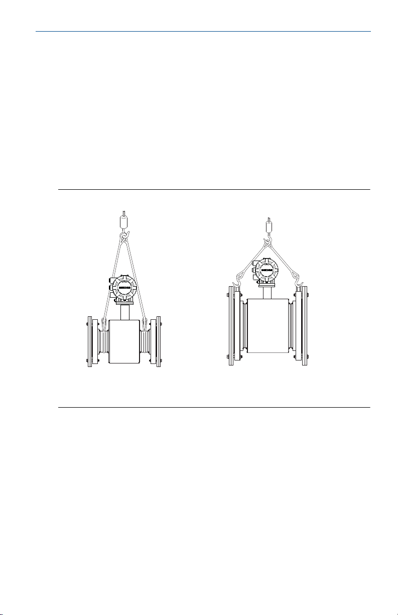
3.1 Upstream/downstream piping
To ensure specified accuracy over widely varying process conditions, install the
sensor with a minimum of five straight pipe diameters upstream and two pipe
diameters downstream from the electrode plane (see Figure 3).
6
Page 7
August 2015
5 Pipe Diameters 2 Pipe Diameters
Flow
Figure 3. Upstream and Downstream Straight Pipe Diameters
Installations with reduced upstream and downstream straight runs are possible.
In reduced straight run installations, the meter may not meet absolute accuracy
specifications. Reported flow rates will still be highly repeatable.
Quick Start Guide
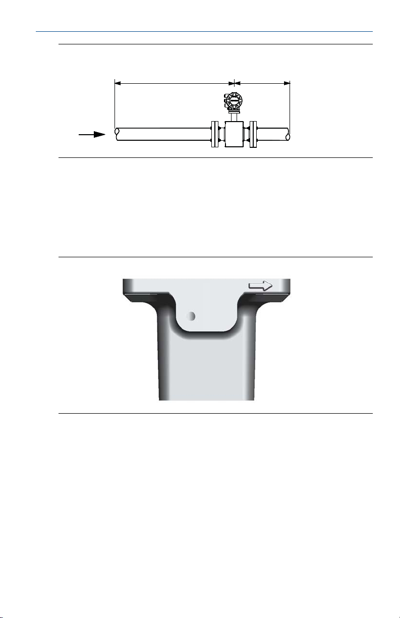
3.2 Flow direction
The sensor should be mounted so that the arrow points in the direction of flow.
See Figure 4.
Figure 4. Flow Direction Arrow
3.3 Sensor location
The sensor should be installed in a location that ensures it remains full during
operation. Vertical installation with upward process fluid flow keeps the
cross-sectional area full, regardless of flow rate. Horizontal installation should be
restricted to low piping sections that are normally full.
7
Page 8

Quick Start Guide
FLOW
FLOW
CORRECT INCORRECT
Figure 5. Sensor Orientation
3.4 Electrode orientation
The electrodes in the sensor are properly oriented when the two measurement
electrodes are in the 3 and 9 o’clock positions or within 45 degrees from the
horizontal, as shown on the left of Figure 6. Avoid any mounting orientation that
positions the top of the sensor at 90 degrees from the vertical position as shown
in Figure 6.
August 2015
Figure 6. Mounting Position
For hazardous location installations, refer to Appendix D of Reference Manual
00809-0400-4444 for sensor orientation pertaining to specific T-code
compliance.
8
Page 9
August 2015
B
A
FLOW
Quick Start Guide
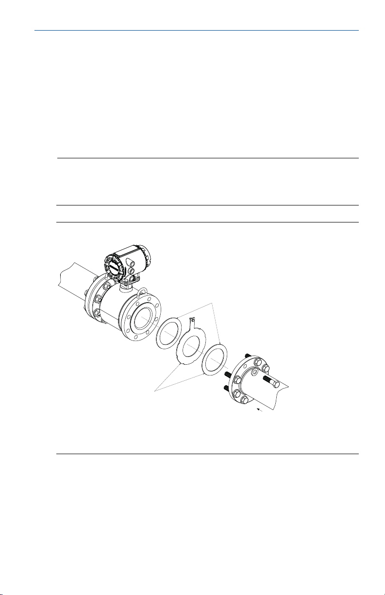
Step 4: Sensor installation
Flanged sensors
4.1 Gaskets
The sensor requires a gasket at each process connection. The gasket material must be
compatible with the process fluid and operating conditions. G askets a re required on
each side of a grounding ring (see Figure 7). All other applications (including
sensors with lining protectors or a grounding electrode) require only one gasket
on each process connection.
Note
Metallic or spiral-wound gaskets should not be used as they will damage the liner face of the
sensor. If spiral wound or metallic gaskets are required for the application, lining protectors
must be used.
Figure 7. Flanged Gasket Placement
A. Grounding Ring and Gasket (Optional)
B. Customer-supplied Gasket
9
Page 10

Quick Start Guide
4.2 Flange bolts
Note
Do not bolt one side at a time. Tighten both sides simultaneously. Example:
1. Snug upstream
2. Snug downstream
3. Tighten upstream
4. Tighten downstream
Do not snug and tighten the upstream side and then snug and tighten the downstream side.
Failure to alternate between the upstream and downstream flanges when tightening bolts
may result in liner damage.
Suggested torque values by sensor line size and liner type are listed in Table 4 for
ASME B16.5 flanges and Table 5 for EN flanges. Consult the factory if the flange
rating of the sensor is not listed. Tighten flange bolts on the upstream side of the
sensor in the incremental sequence shown in Figure 8 to 20% of the suggested
torque values. Repeat the process on the downstream side of the sensor. For
sensors with greater or fewer flange bolts, tighten the bolts in a similar crosswise
sequence. Repeat this entire tightening sequence at 40%, 60%, 80%, and 100% of
the suggested torque values.
If leakage occurs at the suggested torque values, the bolts can be tightened in
additional 10% increments until the joint stops leaking, or until the measured
torque value reaches the maximum torque value of the bolts. Practical
consideration for the integrity of the liner often leads to distinct torque values to
stop leakage due to the unique combinations of flanges, bolts, gaskets, and
sensor liner material.
Check for leaks at the flanges after tightening the bolts. Failure to use the correct
tightening methods can result in severe damage. While under pressure, sensor
materials may deform over time and require a second tightening 24 hours after
the initial installation.
August 2015
Figure 8. Flange Bolt Torquing Sequence
10
Page 11

August 2015
Quick Start Guide
Prior to installation, identify the lining material of the flow sensor to ensure the
suggested torque values are applied.
Table 3. Lining Material
Fluoropolymer liners Other liners
T - PTFE P - Polyurethane
F - ETFE N - Neoprene
A - PFA L - Linatex (Natural Rubber)
K - PFA+
D - Adiprene
Table 4. Suggested Flange Bolt Torque Values for Rosemount 8705 (ASME)
Fluoropolymer liners Other liners
Size
code
005 0.5-in. (15 mm) 8 8 N/A N/A
010 1-in. (25 mm) 8 12 N/A N/A
015 1.5-in. (40 mm) 13 25 7 18
020 2-in. (50 mm) 19 17 14 11
025 2.5-in. (65 mm) 22 24 17 16
030 3-in. (80 mm) 34 35 23 23
040 4-in. (100 mm) 26 50 17 32
050 5-in. (125 mm) 36 60 25 35
060 6-in. (150 mm) 45 50 30 37
080 8-in. (200 mm) 60 82 42 55
100 10-in. (250 mm) 55 80 40 70
120 12-in. (300 mm) 65 125 55 105
140 14-in. (350 mm) 85 110 70 95
160 16-in. (400 mm) 85 160 65 140
180 18-in. (450 mm) 120 170 95 150
200 20-in. (500 mm) 110 175 90 150
240 24-in. (600 mm) 165 280 140 250
300
360
Line size
(1)
30-in. (750 mm) 195 415 165 375
(1)
36-in. (900 mm) 280 575 245 525
Class 150
(pound-feet)
Class 300
(pound-feet)
Class 150
(pound-feet)
(pound-feet)
Class 300
1. Torque values are valid for ASME and AWWA flanges.
11
Page 12

Quick Start Guide
Table 5. Flange Bolt Torque and Load Specifications for 8705 (EN 1092-1)
Fluoropolymer liners (in Newton-meters)
Size code Line size PN10 PN 16 PN 25 PN 40
005 0.5-in. (15 mm) N/A N/A N/A 10
010 1-in. (25 mm) N/A N/A N/A 20
015 1.5-in. (40 mm) N/A N/A N/A 50
020 2-in. (50 mm) N/A N/A N/A 60
025 2.5-in. (65 mm) N/A N/A N/A 50
030 3-in. (80 mm) N/A N/A N/A 50
040 4-in. (100 mm) N/A 50 N/A 70
050 5-in. (125 mm) N/A 70 N/A 100
060 6-in. (150mm) N/A 90 N/A 130
080 8-in. (200 mm) 130 90 130 170
100 10-in. (250 mm) 100 130 190 250
120 12-in. (300 mm) 120 170 190 270
140 14-in. (350 mm) 160 220 320 410
160 16-in. (400 mm) 220 280 410 610
180 18-in. (450 mm) 190 340 330 420
200 20-in. (500 mm) 230 380 440 520
240 24-in. (600 mm) 290 570 590 850
Other liners (in Newton-meters)
Size code
010 1-in. (25 mm) N/A N/A N/A 20
015 1.5-in. (40 mm) N/A N/A N/A 30
020 2-in. (50 mm) N/A N/A N/A 40
025 2.5-in. (65 mm) N/A N/A N/A 35
030 3-in. (80 mm) N/A N/A N/A 30
040 4-in. (100 mm) N/A 40 N/A 50
050 5-in. (125 mm) N/A 50 N/A 70
060 6-in. (150 mm) N/A 60 N/A 90
080 8-in. (200 mm) 90 60 90 110
100 10-in. (250 mm) 70 80 130 170
120 12-in. (300 mm) 80 110 130 180
140 14-in. (350 mm) 110 150 210 280
160 16-in. (400 mm) 150 190 280 410
180 18-in. (450 mm) 130 230 220 280
200 20-in. (500 mm) 150 260 300 350
240 24-in. (600 mm) 200 380 390 560
Line size
PN10
PN 16 PN 25 PN 40
August 2015
12
Page 13

August 2015
Quick Start Guide
Wafer sensors
4.3 Gaskets
The sensor requires a gasket at each process connection. The g asket material
selected must be compatible with the process fluid and operating conditions.
Gaskets are required on each side of a grounding ring. See Figure 9 below.
Note
Metallic or spiral-wound gaskets should not be used as they will damage the liner
face of the sensor.
Figure 9. Wafer Gasket Placement
4.4 Alignment
1. On 1.5-in. through 8-in. (40 through 200 mm) line sizes, Rosemount requires
installing the alignment spacers to ensure proper centering of the wafer sensor
between the process flanges.
2. Insert studs for the bottom side of the sensor between the pipe flanges and
center the alignment spacer in the middle of the stud. See Figure 9 for the bolt
hole locations recommended for the spacers provided. Stud specifications are
listed in Tab le 6.
3. Place the sensor between the flanges. Make sure the alignment spacers are
properly centered on the studs. For vertical flow installations, slide the O-ring
over the stud to keep the spacer in place. See Figure 9. Ensure the spacers
match the flange size and class rating for the process flanges. See Tab le 7 .
4. Insert the remaining studs, washers, and nuts.
5. Tighten to the torque specifications shown in Table 8. Do not over-tighten the
bolts or the liner may be damaged.
13
Page 14

Quick Start Guide
Table 6. Stud Specifications
Nominal sensor size Stud specifications
1.5 through 8-inch (40 through 200 mm) CS, ASTM A193, Grade B7, threaded mounting studs
Table 7. Rosemount Alignment Spacer Table
Dash no.
(-xxxx)
0A15 1.5 40 JIS 10K-20K
0A20 2 50 JIS 10K-20K
0A30 3 80 JIS 10K
0B15 1.5 40 JIS 40K
AA15 1.5 40 ASME- 150#
AA20 2 50 ASME - 150#
AA30 3 80 ASME - 150#
AA40 4 100 ASME - 150#
AA60 6 150 ASME - 150#
AA80 8 200 ASME - 150#
AB15 1.5 40 ASME - 300#
AB20 2 50 ASME - 300#
AB30 3 80 ASME - 300#
AB40 4 100 ASME - 300#
AB60 6 150 ASME - 300#
AB80 8 200 ASME - 300#
DB40 4 100 EN 1092-1 - PN10/16
DB60 6 150 EN 1092-1 - PN10/16
DB80 8 200 EN 1092-1 - PN10/16
DC80 8 200 EN 1092-1 - PN25
DD15 1.5 40 EN 1092-1 - PN10/16/25/40
DD20 2 50 EN 1092-1 - PN10/16/25/40
DD30 3 80 EN 1092-1 - PN10/16/25/40
DD40 4 100 EN 1092-1 - PN25/40
DD60 6 150 EN 1092-1 - PN25/40
DD80 8 200 EN 1092-1 - PN40
RA80 8 200 AS40871-PN16
RC20 2 50 AS40871-PN21/35
RC30 3 80 AS40871-PN21/35
RC40 4 100 AS40871-PN21/35
RC60 6 150 AS40871-PN21/35
RC80 8 200 AS40871-PN21/35
Line size
Flange rating(in) (mm)
August 2015
To order an Alignment Spacer Kit (qty 3 spacers) use p/n 08711-3211-xxxx where
xxxx equals the dash number above.
14
Page 15

August 2015
Quick Start Guide
4.5 Flange bolts
Wafer sensors require threaded studs. See Figure 8 on page 10 for torque
sequence. Always check for leaks at the flanges after tightening the flange bolts.
All sensors require a second tightening 24 hours after initial flange bolt
tightening.
Table 8. Rosemount 8711 Torque Specifications
Size code Line size Pound-feet Newton-meter
015 1.5-in. (40 mm) 15 20
020 2-in. (50 mm) 25 34
030 3-in. (80 mm) 40 54
040 4-in. (100 mm) 30 41
060 6-in. (150 mm) 50 68
080 8-in. (200 mm) 70 95
Step 5: Process reference connection
Figure 10 through Figure 13 illustrate process reference connections only. Earth
safety ground is also required as part of the installation, but is not shown in the
figures. Follow national, local, and plant electrical codes for safety ground.
Use Table 9 to determine which process reference option to follow for proper
installation.
Table 9. Process Reference Installation
Process reference options
Type of pipe Grounding straps Grounding rings
Conductive
Unlined Pipe
Conductive
Lined Pipe
Non-Conductive
Pipe
1.Grounding ring, reference electrode, and lining protectors are not required for proess reference.
Grounding straps per Figure 10 are sufficient.
See Figure 10 See Figure 11
Insufficient
Grounding
Insufficient
Grounding
See Figure 11 See Figure 10 See Figure 11
See Figure 12
(1)
Reference
electrode
See Figure 13
Not
Recommen ded
(1)
Lining
protectors
See Figure 11
See Figure 12
(1)
Note
For line sizes 10-inch and larger, the ground strap may come attached to the sensor body
near the flange. See Figure 14.
15
Page 16

Quick Start Guide
Figure 10. Grounding Straps in Conductive Unlined Pipe or Reference
Electrode in Lined Pipe
Figure 11. Grounding with Grounding Rings or Lining Protectors in
Conductive Pipe
August 2015
Figure 12. Grounding with Grounding Rings or Lining Protectors in
Non-conductive Pipe
16
Page 17

August 2015
Quick Start Guide
Figure 13. Grounding with Reference Electrode in Conductive Unlined Pipe
Figure 14. Grounding for Line Sizes 10-in. and Larger
17
Page 18

Quick Start Guide
A
B
B
C
D
Step 6: Wiring the transmitter
This section covers the wiring between the transmitter and sensor, the Modbus
output, and supplying power to the transmitter. Follow the conduit, cable, and
electrical disconnect requirements in the sections below. For sensor wiring
diagrams, see Figure 29 on page 50. For hazardous locations, refer to Appendix D
of Reference Manual 00809-0400-4444.
6.1 Conduit entries and connections
Conduit entries for the transmitter and sensor are available with 1/2-inch NPT or
M20 connections. Conduit connections should be made in accordance with
national, local, and plant electrical codes. Unused conduit entries should be
sealed with the appropriate certified plugs. The flow sensor is rated IP68 to a
depth of 33 feet (10 meters) for 48 hours. For sensor installations requiring IP68
protection, the cable glands, conduit, and conduit plugs must be rated for IP68.
The plastic shipping plugs do not provide ingress protection.
6.2 Conduit requirements
For installations with an intrinsically safe electrode circuit, a separate conduit
for the coil cable and the electrode cable may be required. Refer to
Appendix D of Reference Manual 00809-0400-4444.
For installations with non-intrinsically safe electrode circuit, or when using the
combination cable, a single dedicated conduit run for the coil drive and
electrode cable between the sensor and the remote transmitter may be
acceptable. Bundled cables from other equipment in a single conduit are likely
to create interference and noise in the system. See Figure 15.
Electrode cables should not be run together and should not be in the same
cable tray with power cables.
Output cables should not be run together with power cables.
Select conduit size appropriate to feed cables through to the flowmeter.
August 2015
Figure 15. Best Practice Conduit Preparation
18
A. Power
B. Output
C. Coil
D. Elec trode
Page 19

August 2015
Socket Module
08732-CSKT-0001
IMS Cable
08732-0179-0003
Quick Start Guide
6.3 Connecting sensor to transmitter
Integral mount transmitters
Integral mount transmitters ordered with a sensor will be shipped assembled and
wired at the factory using an interconnecting cable. (See Figure 16). Use only the
socket module or IMS cable provided by Emerson™ Process Management.
For replacement transmitters, use the existing interconnecting cable from the
original assembly. Replacement cables are available.
Figure 16. Interconnecting Cables
Remote mount transmitters
Cables kits are available as individual component cables or as a combination
coil/electrode cable. Remote cables can be ordered direct from Rosemount using
the kit numbers shown in Table 10. Equivalent Alpha cable part numbers are also
provided as an alternative. To order cable, specify length as quantity desired.
Equal length of component cables is required.
Example: 25 feet = Qty (25) 08732-0065-0001
19
Page 20

Quick Start Guide
Table 10. Component Cable Kits
Standard temperature (-20°C to 75°C)
Cable kit # Description Individual cable Alpha p/n
08732-0065-0001
(feet)
08732-0065-0002
(meters)
08732-0065-0003
(feet)
08732-0065-0004
(meters)
Extended temperature (-50°C to 125°C)
Cable kit # Description Individual cable
08732-0065-1001
(feet)
08732-0065-1002
(meters)
08732-0065-1003
(feet)
08732-0065-1004
(meters)
Kit, Component Cables, Std
Tem p. C oil + Ele ct rod e
Kit, Component Cables, Std
Tem p. C oil + Ele ct rod e
Kit, Component Cables, Std
Tem p. C oil + I. S. Ele ct rod e
Kit, Component Cables, Std
Tem p. C oil + I. S. Ele ct rod e
Kit, Component Cables,
Ext Temp. Coil + Electrode
Kit, Component Cables,
Ext Temp. Coil + Electrode
Kit, Component Cables,
Ext Temp. Coil + I.S. Electrode
Kit, Component Cables,
Ext Temp. Coil + I.S. Electrode
Coil
Electrode
Coil
Electrode
Intrinsically Safe Blue Electrode
Intrinsically Safe Blue Electrode
Intrinsically Safe Blue Electrode
Intrinsically Safe Blue Electrode
Coil
Coil
Coil
Electrode
Coil
Electrode
Coil
Coil
August 2015
518243
518245
518243
518245
518243
518244
518243
518244
Alpha p/n
840310
518189
840310
518189
840310
840309
840310
840309
Table 11. Combination Cable Kits
Coil and electrode cable (-20°C to 80°C)
Cable kit # Description
08732-0065-2001
(feet)
08732-0065-2002
(meters)
08732-0065-3001
(feet)
08732-0065-3002
(meters)
Kit, Combination Cable,
Standar d
Kit, Combination Cable,
Submersible
°C dry/60°C Wet)
(80
(33ft Continuous)
20
Page 21

August 2015
Quick Start Guide
Cable requirements
Shielded twisted pairs or triads must be used. For installations using the individual
coil drive and electrode cable, see Figure 17. Cable lengths should be limited to
less than 500 feet (152 m). Consult factory for length between 500–1000 feet
(152–304 m). Equal length cable is required for each.
For installations using the combination coil drive/electrode cable, see Figure 18.
Combination cable lengths should be limited to less than 330 feet (100 m).
Figure 17. Individual Component Cables
Figure 18. Combination Coil and Electrode Cable
21
Page 22

Quick Start Guide
Cable preparation
When preparing all wire connections, remove only the insulation required to fit
the wire completely under the terminal connection. Prepare the ends of the coil
drive and electrode cables as shown in Figure 19. Limit the unshielded wire length
to less than 1 inch on both the coil drive and electrode cables. Any length of
unsheathed conductor should be insulated. Excessive removal of insulation may
result in an unwanted electrical short to the transmitter housing or other wire
connections. Excessive unshielded lead length, or failure to connect cable shields
properly, may expose the unit to electrical noise, resulting in an unstable meter
reading.
Figure 19. Cable Ends
August 2015
Shock Hazard
Potential shock hazard across remote junction box terminals 1 & 2 (40V).
Explosion Hazard
Electrodes exposed to process. Use only compatible transmitter and approved
installation practices.
For process temperatures greater than 284 °F (140 °C), use a wire rated for 257 °F
(125 °C).
22
Page 23

August 2015
Sensor Transmitter
Modbus (B)
Modbus (A)
Modbus (B)
Modbus (A)
Quick Start Guide
Figure 20. Remote Junction Box Views
Wire Ter mi na l Wire Te rm in al
RED 1 RED 1
BLUE 2 BLUE 2
BLACK 17 Shield 3
YELLOW 18 BLACK 17
WHITE 19 YELLOW 18
WHITE 19
For sensor wiring diagrams, see Figure 29 on page 50. For hazardous locations,
refer to Appendix D of Reference Manual 00809-0400-4444.
6.4 8732EM terminal block connections
Remove the back cover of the transmitter to access the terminal block. See Figure
21 for terminal identification. To connect pulse output and/or discrete
input/output, refer to Reference Manual 00809-0400-4444. For installations with
intrinsically safe outputs, refer to Appendix D of Reference Manual
00809-0400-4444.
Figure 21. Terminal Block Connections
23
Page 24

Quick Start Guide
6.5 Modbus output
The Modbus output is a Modbus RTU signal using RS-485. Follow these cable
recommendations for RS-485 interface (Modbus over serial line).
Cable characteristics
Typ e
Conductor gauge
Characteristic impedance 100–130 ohm
Conductor-to-conductor capacitance <30 pF/ft
Conductor-to-shield capacitance <60 pF/ft
Voltage r atin g 300 V/600 V
Recommended insulation material PVC (<1000 ft) or PE (≥1000 ft)
Bus cable
Bus to be connected device to device. For example, daisy chained (not star
connected).
Maximum 4000 feet depending on speeds, cable, and loads.
Cable shield must be grounded at only one point.
Due to the use of galvanically isolated Modbus connections, a third common wire
is not necessary for this product. If a 3-conductor cable is used, the third wire
should be left unterminated and insulated from ground.
Shielded twiste d pair cable with 2 conductors and a
drain wire, or Ethernet cable of Cat 5/5e/6
20–24 AWG for lengths up to 1000 feet
16–20 AWG for lengths up to 4000 feet
August 2015
Derivations (spurs)
Avoid derivations (spurs) when possible. If required, derivations from the bus
must be as short as possible (65 feet maximum).
Termination
A single 120 ohm terminator should be placed at each physical end of the bus (at
the two most remote bus devices) to minimize reflections in the transmission
cable. Do not place terminators on a spur connection.
Modbus wiring
The Modbus signal is a 24VDC active output.
Wire terminal 1 (B/D1) and terminal 2 (A/D0). See Figure 22.
24
Page 25

August 2015
Modbus A/D0
Modbus B/D1
0.2
0.3
0.4
0.5
0.6
0.7
0.8
0.9
1.0
1.1
1.2
12 16 20 24 28 32 36 40
Supply Current (DC Amps)
Power Supply (DC Volts)
Quick Start Guide
Figure 22. Modbus Wiring—Internal Power
6.6 Powering the transmitter
The Rosemount 8732EM transmitter is available in two models. The AC powered
transmitter is designed to be powered by 90–250VAC (50/60Hz). The DC
powered transmitter is designed to be powered by 12–42VDC. Before connecting
power to the Rosemount 8732EM, be sure to have the proper power supply,
conduit, and other accessories. Wire the transmitter according to national, local,
and plant electrical requirements for the supply voltage. See Figure 23 or Figure
24.
Figure 23. DC power Requirements
Peak inrush is 42A at 42VDC supply, lasting approximately 1ms.
Inrush for other supply voltages can be estimated with:
Inrush (Amps) = Supply (Volts) / 1.0
25
Page 26

Quick Start Guide
0.12
0.14
0.16
0.18
0.20
0.22
0.24
90 110 130 150 170 1 90 210 230 250
Power Supply (VAC)
AC Supply Characteristics
20
22
24
26
28
30
32
34
90 110 130 150 170 190 210 230 250
Apparent Power (VA)
Power Supply (VAC)
Apparent Power (VA)
Figure 24. AC power Requirements
Peak inrush is 35.7A at 250VAC supply, lasting approximately 1ms
Inrush for other supply voltages can be estimated with:
Inrush (Amps) = Supply (Volts) / 7.0
August 2015
Supply wire requirements
Use 10–18 AWG wire rated for the proper temperature of the application. For
wire 10–14 AWG use lugs or other appropriate connectors. For connections in
ambient temperatures above 122 °F (50 °C), use a wire rated for 194 °F (90 °C). For
DC powered transmitters with extended cable lengths, verify that there is a
minimum of 12VDC at the terminals of the transmitter with the device under
load.
Electrical disconnect requirements
Connect the device through an external disconnect or circuit breaker per national
and local electrical code.
Installation category
The installation category for the 8732EM is OVERVOLTAGE CAT II.
Overcurrent protection
The Rosemount 8732EM transmitter requires overcurrent protection of the
supply lines. Fuse rating and compatible fuses are shown in
26
Table 1 2.
Page 27

August 2015
Quick Start Guide
Table 12. Fuse Requirements
Input voltage Fuse rati ng Compatible fuse
90–250VAC rms 1 Amp, 250V, I2t ≥ 1.5 A2s Rating,
12–42VDC 3 Amp, 250V, I2t ≥ 14 A2s Rating,
Fas t Act ing
Fas t Act ing
Bussman AGC-1, Littelfuse 31201.5HXP
Bel Fuse 3AG 3-R, Littelfuse 312003P,
Schurter 0034.5135
Power terminals
See Figure 21 for terminal block connections.
For AC powered transmitter (90–250VAC, 50/60 Hz):
Connect AC Neutral to terminal 9 (AC N/L2) and AC Line to terminal 10
(AC/L1).
For DC powered transmitter:
Connect negative to terminal 9 (DC -) and positive to terminal 10 (DC +).
DC powered units may draw up to 1.2A.
Cover jam screw
For flow meters shipped with a cover jam screw, the screw should be installed
after the instrument has been wired and powered up. Follow these steps to install
the cover jam screw:
1. Verify the cover jam screw is completely threaded into the housing.
2. Install the housing cover and verify the cover is tight against the housing.
3. Using a 2.5 mm hex wrench, loosen the jam screw until it contacts the
transmitter cover.
4. Turn the jam screw an additional
1
/2 turn counterclockwise to secure the cover.
Note
Application of excessive torque may strip the threads.
5. Verify the cover cannot be removed.
27
Page 28

Quick Start Guide
Step 7: Modbus configuration
Note
Each register is identified by its address (or starting address). Depending on the PLC that will
be used to communicate with the transmitter, you may need to subract 1 from the address
or starting address of the register. Refer to your PLC documentation to know if this applies to
you.
Local operator interface
To activate the LOI, press the DOWN arrow. Use the UP, DOWN, LEFT (E), and
RIGHT arrows to navigate the menu structure. Maps of the LOI menus are shown
in Figures
The display can be locked to prevent unintentional configuration changes. The
display lock can be activated by holding the UP arrow for three seconds and then
following the on-screen instructions.
When the display lock is activated, a lock symbol will appear in the lower right
hand corner of the display. To deactivate the display lock, hold the UP arrow for
three seconds and follow the on-screen instructions. Once deactivated, the lock
symbol will no longer appear in the lower right hand corner of the display.
7.1 Address (register 109)
Configures the address of the transmitter for the Modbus network.
25 through 28.
August 2015
7.2 Floating point byte order (register 110)
Sets the order that information is sent by the transmitter.
Register value Byte order
0 0–1–2–3 (default)
1 2–3–0–1
2 1–0–3–2
3 3–2–1–0
7.3 Baud rate (Register 115)
Sets the communication speed of the transmitter.
Register value Baud rate
01200
12400
24800
39600
4 19200 (default)
5 38400
6 57600
7 115200
28
Page 29

August 2015
Quick Start Guide
7.4 Parity (register 116)
Used to configure error-checking methodology for the data.
Register value Parity
0No parity
1Odd
2Even (default)
7.5 Stop bits (register 117)
Sets the last bit of the data packet.
Register value Stop bits
11 bit (default)
22 bits
Step 8: Basic configuration
Once the magnetic flowmeter is installed and power has been supplied, the
transmitter must be configured through the basic setup. These parameters can
be configured through either a local operator interface or a Modbus
communication tool. Configuration settings are saved in nonvolatile memory
within the transmitter. A complete map of the Modbus registries and descriptions
of the more advanced functions is available in Reference Manual
00809-0400-4444.
Basic setup
8.1 Tag (Registers 68–71)
Tag is the quickest and shortest way of identifying and distinguishing between
transmitters. Transmitters can be tagged according to the requirements of your
application. The tag may be up to eight characters long.
29
Page 30

Quick Start Guide
8.2 Flow units (Register 61)
The flow units variable specifies the format in which the flow rate will be
displayed. Units should be selected to meet your particular metering needs.
Volume units Volume units
Register value Units Register value Units
241
242
243
244
132
133
134
135
248
26
15
130
27
28
131
Barrels (31 gal) / sec
Barrels (31 gal) / min
Barrels (31 gal) / hour
Barrels (31 gal) / day
Barrels (42 gal) / sec
Barrels (42 gal) / min
Barrels (42 gal) / hour
Barrels (42 gal) / day
Cubic cm / minute
Cubic feet / second
Cubic feet / minute
Cubic feet / hour
Cubic feet / day
Cubic meters / second
Cubic meters / minute
19
29
22
16
136
235
137
18
30
31
24
17
138
240
Cubic meters / hour
Cubic meters / day
Gallons / second
Gallons / minute
Gallons / hour
Gallons / day
Imperial gallons / sec
Imperial gallons / min
Imperial gallons / hour
Imperial gallons / day
Liters / second
Liters / minute
Liters / hour
Liters / day
August 2015
Mass units Other units
Register value Units Regi ster value Units
73
74
75
76
77
78
79
80
81
82
83
84
85
86
1.Refer to the “Configure special units” section of Reference Manual 00809-0400-4444.
Kilograms / second
Kilograms / minute
Kilograms / hour
Kilograms / day
Metric ton / minute
Metric ton / hour
Metric ton / day
Pounds / second
Pounds / minute
Pounds / hour
Pounds / day
Short tons / minute
Short tons / hour
Short tons / day
20
21
253
30
Feet / second ( default)
Meters / second
Special units
1
Page 31

August 2015
Quick Start Guide
8.3 Line size (Register 65)
The line size (sensor size) must be set to match the actual sensor connected to the
transmitter.
Register value Line size Register value Line size
0
1
2
3
4
5
6
7
8
9
10
11
12
13
14
15
16
17
0.10-in. (2 mm)
0.15-in. (4 mm)
0.25-in. (6 mm)
0.30-in. (8 mm)
0.50-in. (15 mm)
0.75-in. (18 mm)
1-in. (25 mm)
1.5-in. (40 mm)
2-in. (50 mm)
2.5-in. (65 mm)
3-in. (80 mm)
(default)
4-in. (100 mm)
5-in. (125 mm)
6-in. (150 mm)
8-in. (200 mm)
10-in. (250 mm)
12-in. (300 mm)
14-in. (350 mm)
18
19
20
21
22
23
24
25
26
27
28
29
30
31
32
33
34
35
36
16-in. (400 mm)
18-in. (450 mm)
20-in. (500 mm)
24-in. (600 mm)
28-in. (700 mm)
30-in. (750 mm)
32-in. (800 mm)
36-in. (900 mm)
40-in. (1000 mm)
42-in. (1050 mm)
44-in. (1100 mm)
48-in. (1200 mm)
54-in. (1350 mm)
56-in. (1400 mm)
60-in. (1500 mm)
64-in. (1600 mm)
66-in. (1650 mm)
72-in. (1800 mm)
78-in. (1950 mm)
8.4 Calibration number (Registers 413–420)
The sensor calibration number is a 16-digit number generated at the Rosemount
factory during flow calibration and is unique to each sensor and is located on the
sensor tag.
31
Page 32

Quick Start Guide
REV AJ
Totalizers
Diagnostics
Basic Setup
Detailed Setup
View Total A
View Total B
View Total C
Config/Control
Status All
Start All
Stop All
Reset All
Total A
Total B
Total C
Security
Reset Total A
Total A Config
LOI Control
Write Protect
TotA Direction
TotA Units
TotA Reset Cfg
Reset Total B
Total B Config
TotB Direction
TotB Units
TotB Reset Cfg
Reset Total C
Total C Config
TotC Direction
TotC Units
TotC Reset Cfg
LOI Start/Stop
LOI Reset
WP Start/Stop
WP Reset
Figure 25. Totalizer Menu Map
August 2015
32
Page 33

August 2015
Modbus Diag
Diag Controls
Basic Diag
Advanced Diag
Variables
Trims
Status
Empty Pipe
Process Noise
Ground/Wiring
Elec Coating
Elect Temp
Reverse Flow
Cont Meter Ver
Self Test
Pulse Out Test
Empty Pipe
Elect Temp
Flow Limit 1
Flow Limit 2
Total Limit
EP Control
EP Value
EP Trig Level
EP Counts
Ground/Wiring
Process Noise
Elec Coating
Meter Verif
Licensing
Run Meter Ver
View Results
Sensr Baseline
Test Criteria
Measurements
Test Condition
Test Criteria
MV Results
Sim Velocity
Actual Velocity
Flow Sim Dev
Xmtr Cal Verify
Sensor Cal Dev
Sensor Cal
Coil Circuit
Electrode Ckt
Values
Reset Baseline
Recall Values
Coil Resist
Coil Inductnce
Electrode Res
No Flow
Flowing, Full
Empty Pipe
Continual
Coil Resist
Coil Inductnce
Actual Velocity
Electrode Res
License Status
License Key
EC Current Val
EC Limit 1
EC Limit 2
EC Max Value
Reset Max Val
Process Noise
Ground/Wiring
Elec Coating
Meter Verif
DI/DO
Empty Pipe
Elect Temp
Line Noise
5Hz SNR
37Hz SNR
Elec Coating
Signal Power
37Hz Auto Zero
Coil Current
MV Results
EC Current Val
EC Max Value
Digital Trim
37Hz Auto Zero
Universal Trim
Test Criteria
Sim Velocity
Actual Velocity
Flow Sim Dev
Coil Inductnce
Sensor Cal Dev
Coil Resist
Electrode Res
Coils
Electrodes
Transmitter
Manual Results
Continual Res
Manual Results
Continual Res
Coil Resist
Coil Inductnce
Electrode Res
Actual Velocity
Flow Sim Dev
Manual Measure
Continual Meas
Totalizers
Diagnostics
Basic Setup
Detailed Setup
REV AJ
Test Criteria
Sim Velocity
Actual Velocity
Flow Sim Dev
Coil Inductnce
Sensor Cal Dev
Coil Resist
Electrode Res
Test Condition
Test Criteria
MV Results
Sim Velocity
Actual Velocity
Flow Sim Dev
Xmtr Cal Verify
Sensor Cal Dev
Sensor Cal
Coil Circuit
Electrode Ckt
Modbus Status
Listen Only MD
Restart MB Com
Reset MB Confg
Figure 26. Diagnostics Menu Map
Quick Start Guide
33
Page 34

Quick Start Guide
Modbus
Tag
Flow Units
Line Size
Cal Number
Damping
Flow Units
Special Units
Total A Units
Total B Units
Total C Units
Address
Flt Pt Order
Baud Rate
Parity
Stop Bits
Min Resp Delay
Variable Slots
Var Slot 0 Idx
Var Slot 1 Idx
Var Slot 2 Idx
Var Slot 3 Idx
Var Slot 4 Idx
Var Slot 5 Idx
Var Slot 6 Idx
Var Slot 7 Idx
Var Slot 8 Idx
Var Slot 9 Idx
Slot Indices
Slot Variables
Var Slot 0 Val
Var Slot 1 Val
Var Slot 2 Val
Var Slot 3 Val
Var Slot 4 Val
Var Slot 5 Val
Var Slot 6 Val
Var Slot 7 Val
Var Slot 8 Val
Var Slot 9 Val
Totalizers
Diagnostics
Basic Setup
Detailed Setup
REV AJ
Figure 27. Basic Setup Menu Map
August 2015
34
Page 35

August 2015
More Params
Output Config
LOI Config
Sig Processing
Device Info
Device Reset
Coil Frequency
Proc Density
Flow LSL
Flow USL
Modbus
Pulse
DI/DO Config
Reverse Flow
Pulse Scaling
Pulse Width
Pulse Mode
Test
DI/O 1
DO 2
Flow Limit 1
Flow Limit 2
Total Limit
Diag Alert
Flow Display
Language
Disp Auto Lock
Backlight
Operating Mode
SP Config
Coil Frequency
Damping
Lo-Flow Cutoff
Tag
Description
Message
Device ID
Sensor S/N
Sensor Tag
Write protect
Revision Num
Software Rev
Final Asmbl #
DI/O 1 Control
DI 1
DO 1
Control 1
Mode 1
High Limit 1
Low Limit 1
Hysteresis
Total Control
Total Mode
Tot Hi Limit
Tot Low Limit
Hysteresis
Control 2
Mode 2
High Limit 2
Low Limit 2
Hysteresis
Elec Failure
Coil Open Ckt
Empty Pipe
Reverse Flow
Ground/Wiring
Process Noise
Elect Temp
Elec Coat 1
Elec Coat 2
Cont Meter Ver
Coil Over Curr
Sensr Elec Sat
Coil Power Lim
Address
Flt Pt Order
Baud Rate
Parity
Stop Bits
Min Resp Delay
Variable Slots
Var Slot 0 Idx
Var Slot 1 Idx
Var Slot 2 Idx
Var Slot 3 Idx
Var Slot 4 Idx
Var Slot 5 Idx
Var Slot 6 Idx
Var Slot 7 Idx
Var Slot 8 Idx
Var Slot 9 Idx
Slot Indices
Slot Variables
Var Slot 0 Val
Var Slot 1 Val
Var Slot 2 Val
Var Slot 3 Val
Var Slot 4 Val
Var Slot 5 Val
Var Slot 6 Val
Var Slot 7 Val
Var Slot 8 Val
Var Slot 9 Val
Totalizers
Diagnostics
Basic Setup
Detailed Setup
REV AJ
Figure 28. Detailed Setup Menu Map
Quick Start Guide
35
Page 36

Quick Start Guide
Approvals Document
July 24, 2015
08732-AP01, Rev AF
Rosemount 8700M Magnetic Flowmeter Platform
- Ordinary Locations * Ordinary Location *
Canada CSA ***
Glo ba l DEKRA
Glo ba l DEKRA
*** ***
*** ***
Br az il
Br az il
Kore a *** ***
Kore a *** ***
Product Certifications
August 2015
Ord er
Code
FM Non-Incendive
N5
Class I Div 2; DIP
FM Explosion-Proof
K5
Class I Div 1; DIP
CSA Non-Incendive
N6
Class I Div 2; DIP
CSA Explosion-Pr oof
KU
Class I Div 1; DIP
CSA Flameproof, Increased Safety, and Dust.
K6
Zone 0 & 1
ND ATEX Dust ATEX Dust EU DEKRA 14ATEX0071 X
ATEX Non-Sparking
N1
ATEX Dust
ATEX Flameproof with Increased Safety
K1
ATEX Dus t
NF IECEx Dus t IECEx Du st Glo bal DEKRA
IECEx Non- Sparking
N7
IECEx Dust
IECEx Flameproof with Increased Safety
K7
IECEx Dust
EAC Non-Spark ing
N8
EAC Dus t
EAC Flam eproof with Increased Safety
K8
EAC Dus t
INMETRO Non-Sparking
N2
INMETRO Dust
INMETRO Flam eproof with Increase d Safety
K2
INMETRO Dust
KOSHA Non-Sparking
N9
KOSHA Dus t
KOSHA Flam epro of wit h Increas ed Safe ty
K9
KOSHA Dus t
NEPSI Non- Spa rk in g
N3
NEPSI Dus t
NEPSI Flameproof with Increased Safety
K3
NEPSI Dus t
KN CCOE Flame proof with In creas ed Safet y CCOE Incre ased Safe ty w ith Intrin sically Safe Electr odes India PESO P354747/1
Complies w ith only the local country product safety, electromagnetic, pres sure and other applicable regulations.
*
Cannot be used in a classified or zone d hazardous location environment. No ordering code r equired.
Customs Union (Russia, Belarus and Kazakhstan)
**
Planned submittal or in process with Agency.
***
8732EM
Transmitter Rating
FM Non-Ince ndive w ith Intrins ically Safe Electrode s
Class I Div 2; DIP
FM Explosion-Proof with Intrinsically Safe Electrodes
Class I Div 1; DIP
CSA Non-Incen dive wit h Intrins ically Safe Electrode s
Class I Div 2; DIP
CSA Explosion-Proof with Intrinsically Safe Electrodes
Class I Div 1; DIP
CSA Incre ased Safe ty with Intrinsically Safe Electr odes and
Dust. Zone 0 & 1
ATEX Non-Sparking with Intrinsically Safe Electrodes
ATEX Dust
ATEX Increas ed Safety w ith Intr insically Safe Electr odes
ATEX Dus t
IECEx Non-Sparking with Intrinsically Safe Electrodes
IECEx Dust
IECEx Increased Safety with Intrinsically Safe Electrodes
IECEx Dust
EAC Non-Spark ing with Intrinsically Safe Electr odes
EAC Dus t
EAC Increased Safety with Intrinsically Safe Electrodes
EAC Dus t
INMETRO Non-Sparking with Int rinsically Safe Ele ctrode s
INMETRO Dust
INMETRO Increased Safety with Intrinsically Safe Electrodes
INMETRO Dust
KOSHA Non-Spar king w ith Intrins ically Safe Electrod es
KOSHA Dus t
KOSHA Increased Safety with Intrinsically Safe Electrodes
KOSHA Dus t
NEPSI Non- Spark ing w ith Int rins ically Saf e Electr ode s
NEPSI Dus t
NEPSI Increased Safety with Intrinsically Safe Electrodes
NEPSI Dus t
8705M and 8711M/L
Flowtube Rating
Region Age ncy
USA
EU
USA FM 3048793
USA FM 3048793
USA &
Canada
USA CSA 70030489
EU DEKRA 14ATEX0071 X
EU DEKRA 14ATEX0071 X
Russia
**
Russia
**
China NEPSI GYJ15.1180X
China NEPSI GYJ15.1180X
Cer tification
FM 3048793
CSA 70030489
DEK14.0031X
DEK14.0031X
DEK14.0031X
DEKRA -
INMETRO
15.0007 X
DEKRA -
INMETRO
15.0007 X
Num b e r
IECEx
IECEx
IECEx
DEKRA
DEKRA
36
Page 37

August 2015
Approvals Document
July 24, 2015
08732-AP01, Rev AF
Approval Markings and Logos
Symbol
Symbol
Region Meaning of Marking or Symbol
CE European Union
Compliance with all applicable European
Union Directives.
ATEX European Union
Compliance with Equipment and Protective
systems intended for use in Potentially
Explosive Atmospheres directive (ATEX)
(94/9/EC)
C-tick Australia
Compliance with Australian applicable
electromagnetic compatibility standards
FM Approved United States
Compliance with the applicable ANSI
standards.
CSA US = United States
C = Canada
Indicates that the product was tested and has
met the applicable certification requirements
for the noted countries.
Eurasian
Conformity
(EAC)
Eurasian Customs Union
(Russia, Belarus and
Kazakhstan)
Compliance with all of the applicable technical
regulations of the EAC Customs Union
EAC
Hazardous
Location
Eurasian Customs Union
(Russia, Belarus and
Kazakhstan)
Compliance with Technical regulation, (TR CU
012/2011) – The safety of equipm ent for use
in explosive environments.
INMETRO Brazil
Compliance with all of the applicable technical
regulations of Brazil.
NEPSI China
Compliance with all of the applicable technical
regulations of China.
KCS Korea
Compliance with all of the applicable technical
regulations of Korea.
Ordinary Location labels will be marked with CE, C-tick, FM, CSA and EAC logos.
Marking or
Name
Quick Start Guide
37
Page 38

Quick Start Guide
Approvals Document
July 24, 2015
08732-AP01, Rev AF
European Directive Information
A copy of the EC Declaration of Conformity can be found at the end of the Quick Start Guide. The m ost recent
revision of the EC Declaration of Conformity can be found at www.rosemount.com
.
Electro Magnetic Compatibility (EMC) (2004/108/EC)
Transmitter and Flowtube: EN 61326-1: 2013
Transmitters with output code “B” require shielded cable for the 4-20mA output, with shield terminated at the
transmitter.
Low Voltage Directive (LVD) (2006/95/EC)
EN 61010-1: 2010
Ingress Protection Rating for dust and water per EN 60079-0 and EN 60529 – IP66/68 (The IP68 rating only
applies to the flowtube and the remote junction box when the transmitter is remotely mounted. The IP68 rating
does not apply to the transmitter. The IP68 rating is only valid at a depth of 10 meters for 48 hours)
European Pressure Equipment Directive (PED) (97/23/EC)
PED Certification requires the “PD” option code.
CE marked models that are ordered without the “PD” option will be marked “Not Complaint to (97/23/EC)”
Mandatory CE-marking with notified body number 0575, for all flowtubes is located on the flowmeter label.
Category I assessed for conform ity per module A procedures.
Categories II – III assessed for conformity per module H procedures.
QS Certificate of Assessm ent
EC No. 4741-2014-CE-HOU-DNV
Module H Conformity Assessment
8705 M Flanged Flowtubes
Line size 40mm to 900mm (1½-in to 36-in)
EN 1092-1 flanges and ASME B16.5 class 150 and ASME B16.5 Class 300 flanges.
Also available in ASME B16.5 Class 600 flanges in limited line sizes.
8711 Wafer Flowtubes
Line size 40mm to 200mm (1½-in to 8-in)
All other Rosemount Flowtubes – line sizes of 25mm (1-in) and less: Sound Engineering Practice (SEP).
Flowtubes that are SEP are outside the scope of PED and cannot be marked for compliance with PED.
August 2015
38
Page 39

August 2015
Approvals Document
July 24, 2015
08732-AP01, Rev AF
Certifications
Factory Mutual (FM)
Ordinary Location Certification for FM Approvals
As standard, the transmitter and flowtube have been examined and tested to determine that the design meets
basic electrical, mechanical, and fire protection requirements by FM Approvals, a nationally recognized testing
laboratory (NRTL) as accredited by the Federal Occupational Safety and Health Administration (OSHA).
8732EM Transmitter
Note: For Intrinsically Safe (IS) 4-20m A and Pulse Outputs on the 8732EM, output code “B” must be selected.
N5 Non-Incendive for Class I, Division 2, Groups ABCD: T4
Dust-Ignition Proof for Class II/III, Division 1, Groups EFG: T5
-&7D&
Enclosure Type 4X, IP66
Install per drawing 08732-2062
Special Conditions for Safe Use (X):
1. Units marked with “Warning: Electrostatic Charging Hazard” may either use non-conductive paint thicker
than 0.2 mm or non-metallic labeling. Precautions shall be taken to avoid ignition due to electrostatic
charge on the enclosure.
2. The intrinsically safe 4-20mA and pulse output cannot withstand the 500V isolation test due to integral
transient protection. This must be taken into consideration upon installation.
3. Conduit entries must be installed to maintain the enclosure ingress rating of IP66.
4. Unused conduit entries must use either used the Rosemount-supplied blanking plugs, or blanking plugs
certified in accordance with the protection type.
K5 Explos ion-Proof for Class I Division 1, Groups CD: T6
Non-Incendive for Class I, Division 2, Groups ABCD: T4
Dust-Ignition Proof for Class II/III, Division 1, Groups EFG: T5
-&7D&
Enclosure Type 4X, IP66
Install per drawing 08732-2062
Special Conditions for Safe Use (X):
1. Units marked with “Warning: Electrostatic Charging Hazard” may either use non-conductive paint thicker
than 0.2 mm or non-metallic labeling. Precautions shall be taken to avoid ignition due to electrostatic
charge on the enclosure.
2. The intrinsically safe 4-20mA and pulse output cannot withstand the 500V isolation test due to integral
transient protection. This must be taken into consideration upon installation.
3. Conduit entries must be installed to maintain the enclosure ingress rating of IP66.
4. Unused conduit entries must use either used the Rosemount-supplied blanking plugs, or blanking plugs
certified in accordance with the protection type.
Quick Start Guide
39
Page 40

Quick Start Guide
Approvals Document
July 24, 2015
08732-AP01, Rev AF
8705-M and 8711-M/L Flowtube
Note: When used in hazardous (classified) locations:
The 8705-M and 8711-M/L m ay only be used with a certified 8732EM transmitter.
N5 Non-Incendive with Intrinsically Safe Electrodes
for Class I, Division 2, Groups ABCD: T3…T5
Dust-Ignition Proof for Class II/III, Division 1, Groups EFG: T2…T5
-&7D&
Enclosure Type 4X, IP66/68 (IP68 remote mount only)
Install per drawing 08732-2062
Special Conditions for Safe Use (X):
1. Units marked with “Warning: Electrostatic Charging Hazard” may either use non-conductive paint thicker
than 0.2 mm or non-metallic labeling. Precautions shall be taken to avoid ignition due to electrostatic
charge on the enclosure.
2. If used with flammable process fluid, the electrode circuit must be installed as intrinsically safe (Ex ia).
3. Conduit entries must be installed to maintain a minimum enclosure ingress rating of IP66.
4. Unused conduit entries must use either used the Rosemount-supplied blanking plugs, or blanking plugs
certified in accordance with the protection type.
K5 Explos ion-Proof with Intrinsically Safe Electrodes
for Class I Division 1, Groups CD: T3…T6
Non-Incendive with Intrinsically Safe Electrodes
for Class I, Division 2, Groups ABCD: T3…T5
Dust-Ignition Proof for Class II/III, Division 1, Groups EFG: T2…T5
-&7D&
Enclosure Type 4X, IP66/68 (IP68 remote mount only)
Install per drawing 08732-2062
Special Conditions for Safe Use (X):
1. Units marked with “Warning: Electrostatic Charging Hazard” may either use non-conductive paint thicker
than 0.2 mm or non-metallic labeling. Precautions shall be taken to avoid ignition due to electrostatic
charge on the enclosure.
2. If used with flammable process fluid, or if installed in a Class I Division I area, the electrode circuit must
be installed as intrinsically safe (Ex ia).
3. Conduit entries must be installed to maintain a minimum enclosure ingress rating of IP66.
4. Unused conduit entries must use either used the Rosemount-supplied blanking plugs, or blanking plugs
certified in accordance with the protection type.
August 2015
40
Page 41

August 2015
Approvals Document
July 24, 2015
08732-AP01, Rev AF
Canadian Standards Association (CSA)
CLASS 2258 02 - PROCESS CONTROL EQUIPMENT - For Hazardous Locations – To Canadian Requirements.
N6 Class I, Groups A, B, C and D (Intrinsically Safe Output and Electrode circuit)
N6 Class I, Division 2, Groups A, B, C and D (Non-Incendive)
N6 Class II, Division 1, Groups E, F and G (Dust Ignition Proof)
Magnetic Flow Meter – Model 8732EM Transmitter with integral or remote mount to Model 8705M or Model
8711M/L Magnetic Flow Tubes. Enclosure Type 4X and IP 66 Rated.
For Remote Mount Configuration – Temperature Code T4 with an Ambient Operating Temperature Range: -40°C
чdĂчнϲϬΣǁŝƚŚŽƌǁŝƚŚŽƵƚ>ŵĞƚĞƌǁŝƚŚŽƌǁŝƚŚŽƵƚĚŝŐŝƚĂů/KĂŶĚŽƌƉƵůƐĞŽƵƚƉƵƚƐǁŚĞŶŝŶƐƚĂůůĞĚƉĞƌ
Rosemount Drawing 08732-2061.
For Integral Mount Configuration – Ambient Operating Temperature Range: -29°C чdĂчнϲϬΣ. Temperature
Code T3-T6 dependent on line size of Flow Tubes for Process Temperature. The T-Code is defined as per
Rosemount Drawing 08705-00CS and 08732-00CS for ‘N6’ option or ‘KU’ option.
CLASS 2258 82 - PROCESS CONTROL EQUIPMENT - For Hazardous Locations –To US Requirements
KU Class I, Division 1, Groups C and D (Explosion Proof)
N6, KU Class I, Groups A, B, C and D (Intrinsically Safe Output and Electrode circuit
N6, KU Class I, Division 2, Groups A, B, C and D (Non-Incendive)
N6, KU Class II, Division 1, Groups E, F and G (Dust Ignition Proof)
Magnetic Flow Meter – Model 8732EM Transmitter with integral or remote mount to Model 8705M or Model
8711M/L Magnetic Flow Tubes. Enclosure Type 4X and IP 66 Rated.
For Remote Mount Configuration – Temperature Code T6 for Explosion Proof, T5 for Dust Ignition Proof, and T4
for Non-Incendive. Ambient Operating Temperature Range: -ϰϬΣчdĂчнϲϬΣǁŝƚŚŽƌǁŝƚŚŽƵƚ>ŵĞƚĞƌǁŝƚŚ
or without digital I/O and/or pulse outputs when installed per Rosemount Drawing 08732-2061.
For Integral Mount Configuration – Ambient Operating Temperature Range: -ϮϵΣч dĂчнϲϬΣ. Temperature
Code T3-T6 dependent on line size of Flow Tubes for Process Temperature. The T-Code is defined as per
Rosemount Drawing 08705-00CS and 08732-00CS for ‘N6’ option or ‘KU’ option.
Special Conditions of Safe Use:
1. For use with the appropriate 8705M and 8711M/L Flow tubes only.
2. When the 8732EM transmitter is integrally mounted to 8705M or 8711M/L Flow Tubes, the ambient
temperature ranges marked on each product need to be taken into consideration before installation.
The Ambient temperature range for 8732EM transmitter is -ϰϬΣчdĂчнϲϬΣĂŶĚƚŚĞĂŵďŝĞŶƚ
temperature range for 8705M or 8711M/L Flow Tubes is -ϮϵΣчdĂчнϲϬΣ Therefore, the -29°C rating
of the flow tubes will limit the overall cold temperature range of the complete system unless other
approved temperature control methods are employed.
Quick Start Guide
41
Page 42

Quick Start Guide
Approvals Document
July 24, 2015
08732-AP01, Rev AF
August 2015
42
Page 43

August 2015
Approvals Document
July 24, 2015
08732-AP01, Rev AF
Quick Start Guide
43
Page 44

Quick Start Guide
Approvals Document
July 24, 2015
08732-AP01, Rev AF
August 2015
44
Page 45

August 2015
Rosemount 8700M Magnetic Flowmeter Platform
IEC EX & ATEX Approval Document
January 29, 2015,
08732-AP02, Rev AB
1. Equipment Markings – See section VI in the tables on the following pages
a. EC-Type Examination Certificate (ATEX): DEKRA 14ATEX0071_X
b. Certificate of Conformity (IEC Ex): IEC Ex DEK 14.0031X
2. Required Documentation:
a. 08732-2060 Installation Drawing Model 8732EM, 8705M, 8711-M/L ATEX/IEC Ex Hazardous (Ex)
Locations
b. 08732-1504 Installation Drawing, 8732EM Transmitter Wiring
3. Referenced Documentation:
a. 00825-0100-4444.pdf(Hart) & 00825-0400-4444(Modbus), Quick Installation Guide
b. 00809-0100-4444.pdf, Reference Manual
c. 08732-AP01, Approvals Document
4. The Required and Referenced Docum ents listed above address the following items:
a. Instructions for safety i.e.
i. Putting into service
ii. Use
iii. Assembling and dismantling
iv. Maintenance, overhaul and repair
v. Installation
vi. Adjustment
b. Where necessary, training instructions
c. Details which allow a decision to be made as to whether the equipment can be used safely in the
intended area under the expected operating conditions
d. Electrical parameters, maxim um surface temperatures and other limit values
i. Electrical –
1. See document 08732-2060
2.
Rosemount 8732EM Flow Transmitter
12 -42VDC, 1.2A, 15W
Internally powered (Active): Outputs up to 12VDC, 12.1mA,
73mW Externally powered (Passive): Input up to 28VDC,
4-20mA output circuit Internally Powered (Active): Outputs up to 25mA, 24VDC,
600mW Externally Powered (Passive): Input up to 25mA,
MODBUS Internally Powered (Active): Outputs up to 100mA, 3.3VDC,
Coil excitation output
Rosemount 8705-M and 8711-M/L Flowtube
(1)
Coil excitation input
20W max
(1) Provided by the transmitter
e. Special Conditions for Safe Use (X):
Power input
Pulsed circuit
Um
Electrode circuit
90 - 250VAC, 0.45A, 40VA
100mA, 1W
30VDC, 750mW
100mW
250V
500mA, 40V max, 9W max
500mA, 40V max,
5V,200uA, 1mW
Quick Start Guide
45
Page 46

Quick Start Guide
Rosemount 8700M Magnetic Flowmeter Platform
IEC EX & ATEX Approval Document
January 29, 2015,
08732-AP02, Rev AB
i. For processes requiring EPL Ga and Gb, rated equipment: electrode, grounding ring, and lining
protector materials Titanium and Zirconium are not allowed.
ii. When “Special Paint Systems” are applied, instructions for safe use regarding potential
electrostatic charging hazard have to be followed.
iii. Terminals 1,2,3,4, for data communication, cannot withstand the 500 V isolation test between
signal and ground, due to integral transient protection. This must be taken into account upon
installation.
iv. Conduit entries must be installed to maintain the enclosure ingress rating of IP66.
v. In order to maintain the ingress protection level on the M3 and M4 electrode housing, the copper
crush washer that seals the electro de access plug shall be replaced when the plug is reinstalled.
The copper crush washer is one time use only.
vi. The flow tube and transmitter are not allowed to be thermally insulated.
vii. The property class of the special fasteners which attach the Magnetic Flow T ube or Transmitter
Remote Junction Box to the Magnetic Transmitter is A2-70 or A4-70 SST.
viii. For information on the dimensions of the flam eproof joints the manufacturer shall be contacted.
ix. The Magnetic Flow Meter Tube contains nonconductive liners over the grounded tube. For
process requiring EPL Ga, precautions shall be taken to avoid the liner being charged by the flow
of nonconductive media.
f. Where necessary, the essential characteristics of tools which may be fitted to the equipment
g. List of the standards, including the issue date, with which the equipment is declared to comply:
i. ATEX - EN 60079-0: 2012 +A11, EN 60079-1: 2007, EN 60079-7: 2007. EN 60079-11: 2012, EN
60079-15: 2010, EN 60079-26: 2007, EN 60079-31: 2014
ii. IEC EX - IEC 60079-0: 2011, IEC 60079-1: 2007, IEC 60079-7: 2006 IEC 60079-11: 2011, IEC
60079-15: 2010, IEC 60079-26: 2006, IEC 60079-31: 2013
h. Supply wire requirements;
Use 10 - 18 AWG wire rated for the proper temperature of the application. For wire 10 - 14 AWG use lugs
or other appropriate connectors. For connections in ambient temperatures above 122°F (50 °C), use a
wire rated for 194 °F (90 °C).
i. Contact address;
i. Rosemount Inc.
12001 Technology Drive
Eden Prairie
MN 55344
United States of America
August 2015
46
Page 47

August 2015
Rosemount 8700M Magnetic Flowmeter Platform
IEC EX & ATEX Approval Document
January 29, 2015,
08732-AP02, Rev AB
Nomenclature Magnetic Flow Transmitter Model 8732EM and electrical data
Explanation
Value Explanation
II Transmitter Mount
III Transmitter Power Supply
IV Outputs
B
Pulse Output
4 - 20 mA Intrinsically Safe Output with digital HART
Protocol & Intrinsically Safe Scalable Pulse Output
V Conduit entries
VI Safety Approval Option
K1 ATEX
K7 IECEx
N1 ATEX
N7 IECEx
ND ATEX
NF IECEx
** Intrinsically Safe Output (see IV) option only
VII Display Option
VIII Remote Cable Option
IX Options
SH
Stainless Steel Electronics Housing
8732EM R 1 B 2 K1 … M4 RT50 … SH … V2 … F090…
I II III IV V VI VII VIII IX X
Designation
I Model 8732EM Magnetic Flow Transmitter – Field Mount
RTRemote Mount
Integral Mount
12AC (90 - 250 Vac, 50 / 60 Hz), not f or Ex nA
DC (12 - 42 Vdc)
4 - 20 mA with digital HART Protocol & Scalable
A
Quick Start Guide
X Specials F090x Special Paint Systems *****
M
Modbus RS-485
1 or 4
½-14 NPT female
2 or 5
CM20, M20 female
II 2 (1) G Ex d e [ia Ga] IIC T 6…T3 Gb
II 2 D Ex tb IIIC T80 °C…T200 °C Db
II 2 (1) G Ex d [ia Ga] IIC T6…T 3 Gb *
II 2 D Ex tb IIIC T80 °C…T200 °C Db
Ex d e [ia Ga] IIC T6…T3 Gb
Ex tb IIIC T80 °C…T200 °C Db
Ex d [ia Ga] IIC T6…T3 Gb *
Ex tb IIIC T80 °C…T200 °C Db
II 3 (1) G Ex nA [ia Ga] IIC T4…T3 Gc ***
II 2 D Ex tb IIIC T80 °C…T200 °C Db
Ex nA [ia Ga] IIC T4…T3 Gc ***
Ex tb IIIC T80 °C…T200 °C Db
II 2 D Ex tb IIIC T80 °C…T200 °C Db
II 2 D Ex tb IIIC T80 °C…T200 °C Db
II (1) G [Ex ia Ga] IIC **
Ex tb IIIC T80 °C…T200 °C Db
Ex tb IIIC T80 °C…T200 °C Db
[Ex ia Ga] IIC **
NOTE: * Integral Mount (see II) option only
M4M5LOI
RTxx ****
RHxx ****
--
Vx
*** DC Transmitter Power Supply only (12 - 42 Vdc)
Display
Standard Temperature Component
Extended Temperature Component
NOTE: **** Length = xx x10 ft, max. 500 ft
Aluminum, standard paint
Special Paint Systems *****
NOTE: ***** Subject to special conditions for safe use.
47
Page 48

Quick Start Guide
Rosemount 8700M Magnetic Flowmeter Platform
IEC EX & ATEX Approval Document
January 29, 2015,
08732-AP02, Rev AB
IV Line Size
to
to
V Electrode Housing *
M1
M2
M3
Category 2 G or 3 G, EPL Gb or Gc
Category 1/2 G or 1/3 G, EPL Ga/Gb or Ga/Gc
Category 1/2 G or 1/3 G, EPL Ga/Gb or Ga/Gc
VI Safety Approvals
K1 ATEX
K7 IECEx
N1 ATEX
N7 IECEx
VII
Custom See special conditions for safe use
VIII
Custom See special conditions for safe use
IX
B3 Integral Mount with Model 8732EM
X
J1 CM20, M20 female
XI
XIII
Nomenclature Magnetic Flow Tube Model 8705-M and electrical data
8705
… S A 005 … M4 K1 … G1 L1 B3 … J1 SJ … V1 … SH … F090x
I II III IV V VI VII VIII IX X XI XII XIII XIV
Designation Explanation Value Explanation
I Model 8705 Magnetic Flowtube
II Electrode Material Custom See special conditions for safe use
III Electrode Types Custom Seal of electrodes comply with IEC 61010-1
XII Special paint options Vx Special Paint Systems ***
XIV Specials F090x Special Paint Systems ***
½” NPS (15 mm)
005
360
36” NPS (900 mm)
Category 2 G or 3 G, EPL Gb or Gc
M0
M4
Category 1/2 G or 1/3 G, EPL Ga/Gb or Ga/Gc
II 1/2 G Ex e ia IIC T5…T3 Ga/Gb *
Grounding rings
material
Lining protector
material
Mounting
Configuration
Optional conduit
entries
Remote Junction Box
(RJB) material
Wrapper (housing)
material
ND ATEX
NF IECEx Ex tb IIIC T 80 °C…T 200 °C Db
--
SJ
--
SH
II 2 D Ex tb IIIC T 80 °C…T 200 °C Db
II 2 G Ex e ib IIC T5…T3 Gb **
II 2 D Ex tb IIIC T 80 °C…T 200 °C Db
Ex e ia IIC T5…T3 Ga/Gb *
Ex tb IIIC T 80 °C…T 200 °C Db
Ex e ib IIC T5…T3 Gb **
Ex tb IIIC T 80 °C…T 200 °C Db
II 1/3 G Ex nA ia IIC T5…T3 Ga/Gc *
II 2 D Ex tb IIIC T 80 °C…T 200 °C Db
II 3 G Ex nA ic IIC T5…T3 Gc *
II 2 D Ex tb IIIC T 80 °C…T 200 °C Db
Ex nA ia IIC T5…T3 Ga/Gc *
Ex tb IIIC T 80 °C…T 200 °C Db
Ex nA ic IIC T5…T3 Gc *
Ex tb IIIC T 80 °C…T 200 °C Db
II 2 D Ex tb IIIC T 80 °C…T 200 °C Db
NOTE: * Electrode Housing M2, M3 and M4 only
Aluminum, Standard Paint
316 Stainless Steel
Carbon Steel (w. Aluminum RJB), Standard Paint
316 Stainless Steel (w. Stainless Steel RJB)
NOTE: *** Subject to special conditions for safe use.
** Electrode Housing M0 and M1 only
line sizes 8”- 36”
line sizes 0.5” – 6” /
line sizes 8”- 36”
line sizes 0.5” – 6” /
**
August 2015
**
48
Page 49

August 2015
Rosemount 8700M Magnetic Flowmeter Platform
IEC EX & ATEX Approval Document
January 29, 2015,
08732-AP02, Rev AB
Nomenclature Magnetic Flow Tube Model 8711-M/L and electrical data
IV Line Size
to
to
V
VI Safety Approvals
K7 IECEx
N1 ATEX
N7 IECEx
VII
Custom See special conditions for safe use
VIII
J1 CM20, M20 female
IX
Remote Junction
Box material
X
Vx Special Paint Systems **
8711 … S A 15F L … K1 … G1 … J1 SJ … V1 … F090x
I II III IV V VI VII VIII IX X XI
Designation
I Model 8711 Magnetic Flow Tube
II Electrode Material Custom See special conditions for safe use
III Electrode Types Custom Seal of electrodes com ply with IEC 61010-1.
XI Specials F090x Special Paint Systems **
Explanation
Mounting
Configuration
Grounding rings
material
Optional conduit
entries
Special paint
options
Value Explanation
1½” NPS (40 mm)
015
080
8” NPS (900 mm)
LMRemote Mount from Transmitter
Integral Mount with Transmitter
K1
ATEX
ND ATEX II 2 D Ex tb IIIC T 80 °C…T 200 °C Db
NF IECEx Ex tb IIIC T 80 °C…T 200 °C Db
II 2 G Ex e ib IIC T5…T3 Gb
II 2 D Ex tb IIIC T 80 °C…T 200 °C Db
Ex e ib IIC T5…T3 Gb
Ex tb IIIC T 80 °C…T 200 °C Db
II 3 G Ex nA ic IIC T5…T3 Gc
II 2 D Ex tb IIIC T 80 °C…T 200 °C Db
Ex nA ic IIC T5…T3 Gc
Ex tb IIIC T 80 °C…T 200 °C Db
--SJAluminum, Standard Paint *
316 Stainless Steel *
NOTE:* Flowtube with Carbon Steel Wrapper (housing)
NOTE: ** Subject to special conditions for saf e use.
Quick Start Guide
49
Page 50

Quick Start Guide
Figure 29. Rosemount 8732EM Installation and Wiring Drawings
August 2015
50
Page 51

August 2015
Quick Start Guide
51
Page 52

Global Headquarters
Emerson Process Management
6021 Innovation Blvd
Shakopee, MN 55379, USA
+1 800 522 6277 or +1 303 527 5200
+1 303 530 8459
Flow.Support@Emerson.com
North America Regional Office
Emerson Process Management
7070 Winchester Circle
Boulder, CO 80301 USA
+1 800 522 6277 or +1 303 527 5200
+1 303 530 8459
Flow.Support@Emerson.com
Latin America Regional Office
Emerson Process Management
Multipark Office Center
Turrubares Building, 3rd & 4th floor
Guachipelin de Escazu, Costa Rica
+1 506 2505-6962
+1 954 846 5121
Flow.Support@Emerson.com
Europe Regional Office
Emerson Process Management Flow B.V.
Neonstraat 1
6718 WX Ede
The Netherlands
+31 (0) 318 495555
+31 (0) 318 495556
Flow.Support@Emerson.com
00825-0400-4444
Quick Start Guide
00825-0400-4444, Rev. AA
August 2015
Asia Pacific Regional Office
Emerson Process Management Asia Pacific Pte Ltd
1 Pandan Crescent
Singapore 128461
+65 6777 8211
+65 6777 0947
APflow.support@emerson.com
Middle East and Africa Regional Office
Emerson Process Management
Emerson FZE P.O. Box 17033,
Jebel Ali Free Zone - South 2
Dubai, United Arab Emirates
+971 4 8118100
+971 4 8865465
FlowTechnicalSupport@emerson.com
Standard Terms and Conditions of Sale can be found at:
www.rosemount.com\terms_of_sale.
The Emerson logo is a trademark and service mark of Emerson
Electric Co.
Rosemount and Rosemount logotype are registered
trademarks of Rosemount Inc.
All other marks are the property of their respective owners.
© 2015 Rosemount Inc. All rights reserved.
 Loading...