

Rosemount 8705 Data sheet
Product Data Sheet
00813-0100-4444, Rev AI
Rosemount™ 8700M Magnetic Flowmeter
Platform
May 2019
■
Industry leading performance:
— Standard reference accuracy of 0.25% of rate
— High reference accuracy of 0.15% of rate (optional)
■
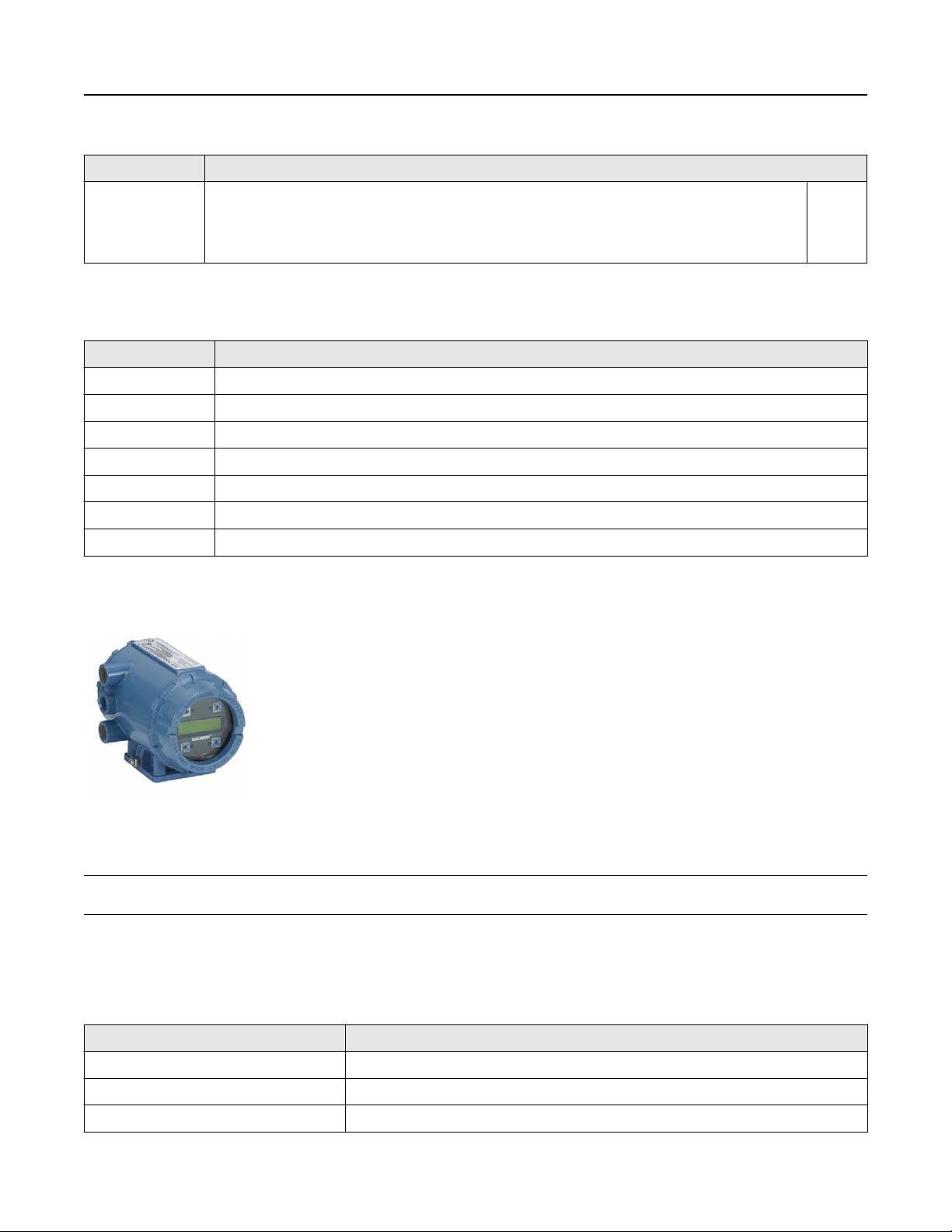
Rosemount 8732 Transmitter: Integral and remote mount designs, backlit display, and explosion-proof housing
■
Rosemount 8712 Transmitter: Wall mount design, backlit display, 15-Button tactile key pad
■
Available in 4-20mA with HART®, FOUNDATION™ Fieldbus, Modbus® RS-485, Intrinsically Safe (I.S.) outputs, Process Diagnostics,
and SMART™ Meter Verification to improve reliability and performance
■
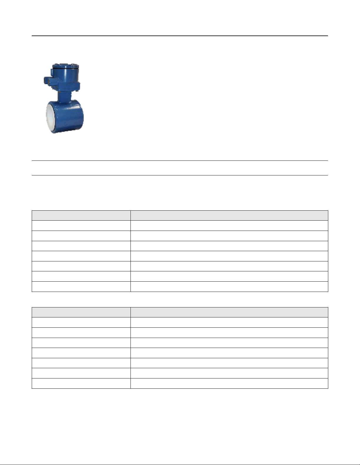
Rosemount 8705 Flanged Sensor: Fully welded sensor for maximum protection
■
Rosemount 8711 Wafer Sensor: Economical, compact, fully welded, and lightweight sensor, provided with alignment spacers
for easy installation
■
Rosemount 8721 Hygienic (Sanitary) Sensor: Specifically designed for food, beverage, and life sciences applications
May 2019
Product Selection Guide
The Rosemount 8700M Magnetic Flowmeter Platform is available in a variety of sensor styles and configurations to ensure
compatibility with virtually all applications and installations.
■
For transmitter details see Table 87 and Table 88.
■
For sensor styles and details see Table 89.
■
For available lining materials see Table 90.
■
For available electrode materials and electrode types see Table 91 and Table 92.
■
For process reference (grounding) options see Table 93 and Table 94.
Other liner and electrode materials not listed may be available. Contact your local sales representative. For further guidance on
selecting materials, refer to the Magnetic Flowmeter Material Selection Guide located on Rosemount.com (Technical Data Sheet
Number 00816-0100-3033). For more information regarding the available product offering see the ordering information, Table 6
thru Table 86.
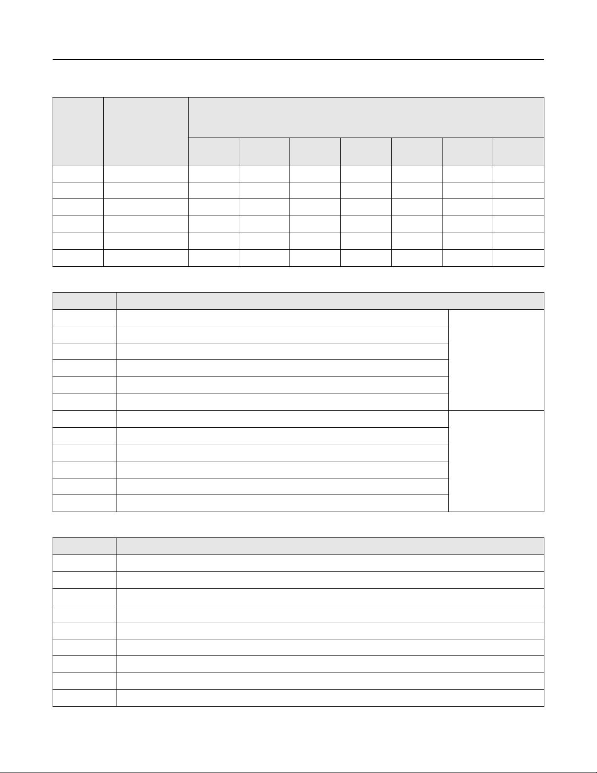
Transmitter selection
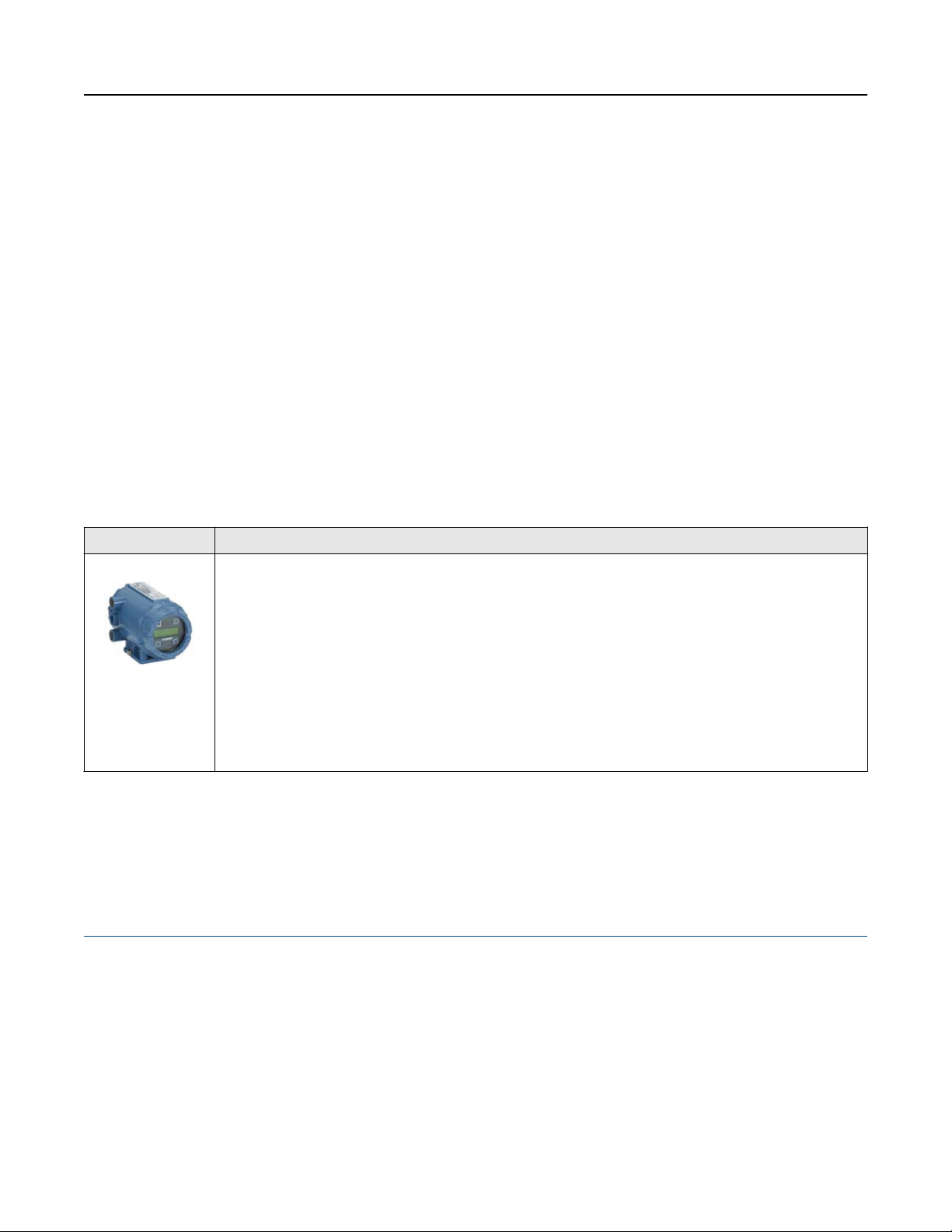
Transmitter General characteristics
8732
■
Integral and remote configurations available
■
HART/Analog and Pulse outputs available
■
FOUNDATION™ Fieldbus and pulse output available
■
Modbus RS-485 and Pulse output available
■
Advanced Diagnostics available
■
LCD display (optional)
— With optional optical switch local operator interface
■
Two discrete channels (optional)
(1)
Contents
Product Selection Guide.................................................................................................................................................................... 2
Magmeter Diagnostics...................................................................................................................................................................... 4
Magnetic Flowmeter Sizing............................................................................................................................................................... 5
Ordering Information........................................................................................................................................................................ 7
Product Specifications..................................................................................................................................................................... 37
Product Certifications......................................................................................................................................................................63
Dimensional drawings..................................................................................................................................................................... 64
2 www.rosemount.com

May 2019
Transmitter General characteristics
8712
HART or Modbus protocol only.
(1)
■
Wall mount configuration
■
HART/Analog and Pulse outputs available
■
Modbus RS-485 and Pulse output available
■
FOUNDATION™ Fieldbus and pulse output available
■
Advanced Diagnostics available
■
Local LCD display (optional)
— With optional 15 button tactile key pad
■
Two discrete channels (optional)
Sensor selection
Table 1: Sensor Selection
Sensor General characteristics
8705
■
Standard process sensor
■
Flanged process connections
■
Welded, sealed coil housing
■
½ -in. (15mm) to 36-in. (900mm)
■
Standard, reference, bullet-nose, and flat electrodes available
(1)
8711
8721
■
Economical, compact, and lightweight alternative to flanged sensors
■
Wafer (flangeless) design
■
Welded, sealed coil housing
■
1½ -in. (40mm) to 8-in. (200mm)
■
Standard, reference, and bullet-nose electrodes available
■
Hygienic (sanitary) sensor
■
Designed for food, beverage, and pharmaceutical applications
■
Variety of industry standard process connections
■
½ -in. (15mm) to 4-in. (100mm)
■
3-A certified
■
Suitable for CIP/SIP
www.rosemount.com 3
May 2019
Magmeter Diagnostics
Rosemount diagnostics reduce cost & improve output by enabling new practices
Rosemount Magnetic Flowmeters provide device diagnostics that detect and warn of abnormal situations throughout the life of the
meter - from installation to maintenance and meter verification. With Rosemount Magnetic Flowmeter diagnostics enabled, plant
availability and throughput can be improved, and costs through simplified installation, maintenance and troubleshooting can be
reduced.
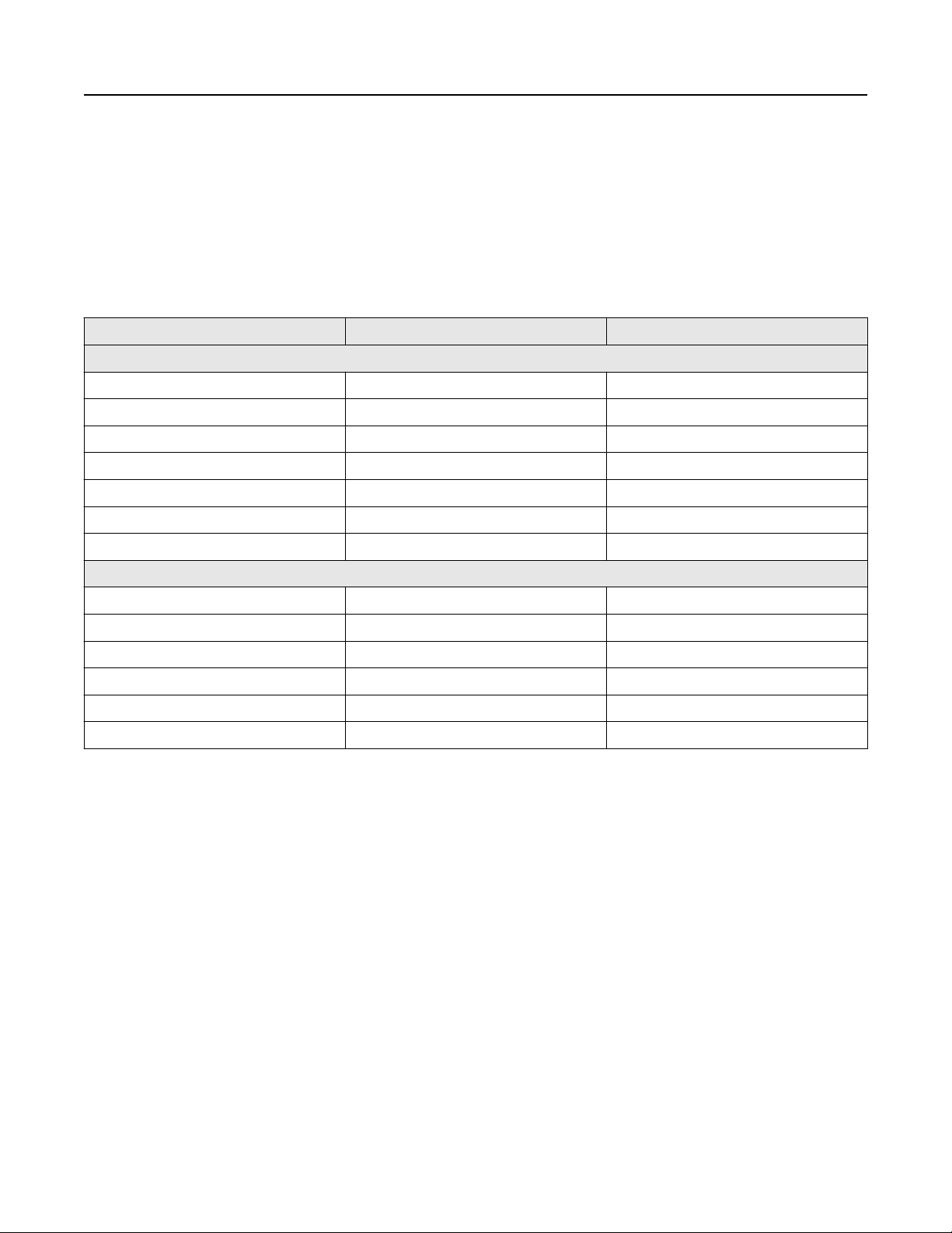
Table 2: Magnetic flowmeter diagnostics
Diagnostic name Diagnostic category Product capability
Basic diagnostics
Tunable Empty Pipe Process Standard
Electronics Temperature Meter Health Standard
Coil Fault Meter Health Standard
Transmitter Fault Meter Health Standard
Reverse Flow Process Standard
Coil current Maintenance Standard
Electrode saturation Process/Maintenance Standard
Advanced diagnostics
High Process Noise Process Suite 1 (DA1)
Grounding and Wiring Fault Installation Suite 1 (DA1)
Coated Electrode Detection Process Suite 1 (DA1)
Commanded Smart Meter Verification Meter Health Suite 2 (DA2)
Continuous Smart Meter Verification Meter Health Suite 2 (DA2)
4-20 mA Loop Verification
Available with HART output only.
(1)
(1)
Installation Suite 2 (DA2)
Options for accessing diagnostics
Rosemount Magmeter Diagnostics can be accessed through the Local Operator Interface (LOI), ProLink® III v3.1, a HART Field
Communicator
diagnostics or for diagnostic availability on existing transmitters.
(1)
, and AMS® Suite: Intelligent Device Manager
(1)
. Contact your local Rosemount representative to activate
Access diagnostics through the LOI for quicker installation, maintenance, and meter verification
Rosemount Magnetic Flowmeter Diagnostics are available through the LOI to simplify maintenance.
Access diagnostics through ProLink III v. 3.0 (HART)/ProLink III v. 3.1 (HART, Modbus)
Simplify maintenance and troubleshooting practices by utilizing ProLink III v3.0/v3.1 to access diagnostics and troubleshooting
information, log variable data, run SMART Meter Verification, and print verification reports.
Access diagnostics through AMS Intelligent Device Manager
The value of the diagnostics increases significantly when AMS Intelligent Device Manager is used. AMS Intelligent Device Manager
provides a simplified screen flow and procedures for how to respond to the diagnostic messages.
(1) Available with HART output only.
(1)
for the ultimate value
4 www.rosemount.com
Velocity =
Flow Rate
Factor
Velocity =
300 (gpm)
39.679
Velocity = 7.56 ft/s
Velocity =
800 (L/min)
492.78
Velocity = 1.62 m/s
May 2019
Magnetic Flowmeter Sizing
Selecting the appropriate sensor size is an important step when considering a magnetic flowmeter. The physical properties of the
process fluid, as well as the fluid velocity should be considered. It may be necessary to select a flow sensor that is larger or smaller
than the adjacent piping to ensure the fluid velocity is in the recommended flow range for the application.
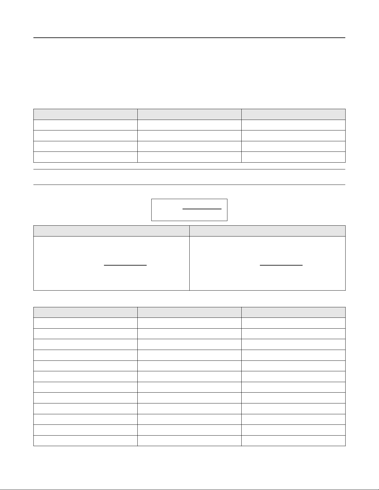
Table 3: Sizing guidelines
Application Velocity range (ft/s) Velocity range (m/s)
Normal Service 0–39 0–12
Preferred Service 2–20 0.6–6.1
Abrasive Slurries 3–10 0.9–3.1
Non-Abrasive Slurries 5–15 1.5–4.6
Note
Operation outside these guidelines may also give acceptable performance.
To convert flow rate to velocity, use the appropriate factor listed in Table 4 and the following equation:
Example: English units Example: SI units
Magmeter Size: 4 in. (factor from Table 4 = 39.679) Normal
Flow Rate: 300 GPM
Magmeter Size: 100 mm (factor from Table 4 = 492.78)Normal
Flow Rate: 800 L/min
Table 4: Line size vs. conversion factor
Nominal line size—Inches (mm) Gallons per minute factor Liters per minute factor
½ (15) 0.947 11.762
1 (25) 2.694 33.455
1½ (40) 6.345 78.806
2 (50) 10.459 129.89
2 ½ (65) 14.923 185.33
3 (80) 23.042 286.17
4 (100) 39.679 492.78
5 (125) 62.356 774.42
6 (150) 90.048 1,118.3
www.rosemount.com 5
8 (200) 155.93 1,936.5
10 (250) 245.78 3,052.4
12 (300) 352.51 4,378.0

Table 4: Line size vs. conversion factor (continued)
Nominal line size—Inches (mm) Gallons per minute factor Liters per minute factor
14 (350) 421.70 5,237.3
16 (400) 550.80 6,840.6
18 (450) 697.19 8,658.6
20 (500) 866.51 10,761
24 (600) 1,253.2 15,564
30 (750) 2006.0 24,913
36 (900) 2,935.0 36,451
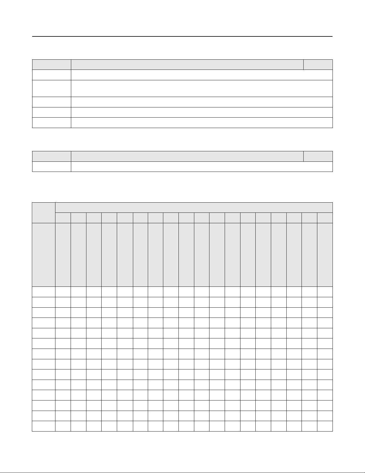
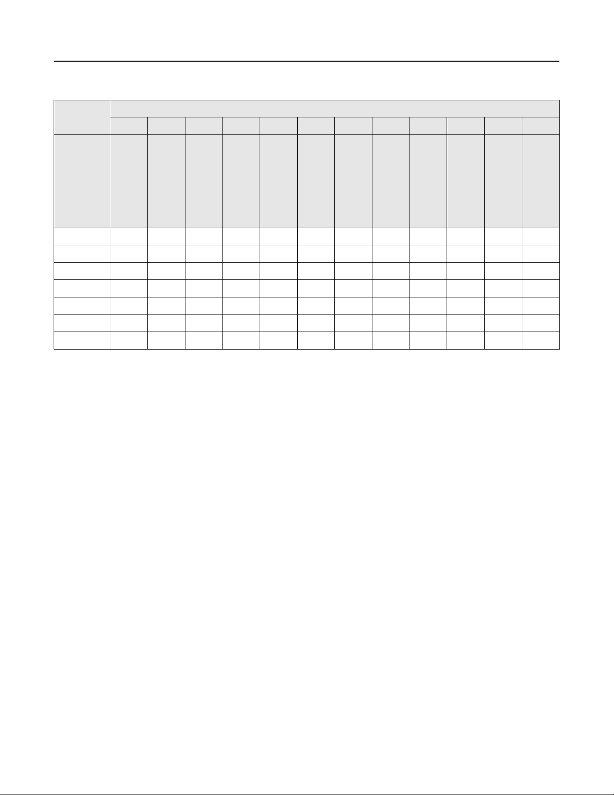
Table 5: Line size vs. velocity/rate
May 2019
Nominal
line size in
inches
(mm)
½ (15) 0.038 0.947 2.841 37.287 0.141 3.529 11.76 141.15
1 (25) 0.108 2.694 8.081 106.05 0.401 10.04 33.45 401.46
1½ (40) 0.254 6.345 19.04 249.82 0.946 23.64 78.81 945.67
2 (50) 0.418 10.459 31.38 411.77 1.559 38.97 129.89 1,558.7
2½ (65) 0.597 14.923 44.77 587.51 2.224 55.60 185.33 2,224.0
3 (80) 0.922 23.042 69.13 907.17 3.434 85.85 286.17 3,434.0
4 (100) 1.587 39.679 119.04 1,562.2 5.913 147.84 492.78 5,913.4
5 (125) 2.494 62.356 187.07 2,454.9 9.293 232.33 774.42 9,293.0
6 (150) 3.602 90.048 270.14 3,545.2 13.42 335.50 1,118.3 13,420
8 (200) 6.237 155.93 467.79 6,138.9 23.24 580.96 1,936.5 23,238
10 (250) 9.831 245.78 737.34 9,676.3 36.63 915.73 3,052.4 36,629
12 (300) 14.10 352.51 1,057.5 13,878 52.54 1,313.4 4,378.0 52,535
Minimum/maximum flow rate
Gallons per minute Liters per minute
at 0.04 ft/s
(low-flow
cutoff)
at 1 ft/s
(min range
setting)
at 3 ft/s at 39.37 ft/s
(max range
setting)
at 0.012
m/s
(low-flow
cutoff)
at 0.3 m/s
(min range
setting)
at 1 m/s at 12 m/s
(max range
setting)
14 (350) 16.87 421.71 1,265.1 16,603 62.85 1,571.2 5,237.3 62,848
16 (400) 22.03 550.80 1,652.4 21,685 82.09 2,052.2 6,840.6 82,087
18 (450) 27.89 697.19 2,091.6 27,448 103.90 2,597.6 8,658.6 103,903
20 (500) 34.66 866.51 2,599.5 34,114 129.14 3,228.4 10,761 129,137
24 (600) 50.13 1,253.2 3,759.6 49,339 186.77 4,669.2 15,564 186,769
30 (750) 80.24 2,006.0 6,018.0 78,976 298.96 7,474.0 24,913 298,959
36 (900) 117.40 2,935.0 8,805.1 115,553 437.42 10,935 36,451 437,416
6 www.rosemount.com

May 2019
Upstream and downstream piping
To ensure specified accuracy over widely varying process conditions, it is recommended to install the sensor with a minimum of five
straight pipe diameters upstream and two pipe diameters downstream from the electrode plane.
Figure 1: Upstream and downstream straight pipe diameters
A. Five pipe diameters (upstream)
B. Two pipe diameters (downstream)
C. Flow direction
Installations with reduced upstream and downstream straight runs are possible. In reduced straight run installations, the meter
may not meet accuracy specifications. Reported flow rates will still be highly repeatable.
Sensor grounding
A reliable ground path is required between the sensor and the process fluid. Optional grounding rings, process reference electrode,
and lining protectors are available with the sensor to ensure proper grounding. See Table 93 and Table 94.
Ordering Information
Rosemount 8712EM Transmitter
The Rosemount 8712EM Transmitter with “Best in Class” performance, coupled with advanced diagnostics, provides unparalleled
process management capabilities. An optional backlit 2-line by 16-character display/local operator interface is available. The
transmitter can be configured using the 15 button tactile keypad.
Note
The starred (★) offerings represent the most common options, and should be selected for best delivery.
Model code structure
Example model code with one selection out of each category: 8712EM R 1 A 1 N5 DA1 AX M4 C1 GM Q4 HR7 RT05
www.rosemount.com 7

Table 6: Requirements - select one from each available choice
Example code Category
8712EM Base model—Magnetic Flowmeter Transmitter - Wall Mount
R Mounting style (Table 8)
1 Power supply (Table 9)
A Outputs (Table 10)
1 Conduit entry (Table 11)
Table 7: Options - select only as needed
Example code Category
N5 Hazardous area certifications (Table 12)
DA1 Advanced diagnostics (Table 13)
AX Discrete input/discrete output (Table 14)
M4 Display (Table 15)
C1 Miscellaneous (Table 16)
GM Conduit electrical connections (Table 17)
May 2019
Q4 Quality certificate (Table 18)
HR7 Revision configuration (Table 19)
RT05 Remote cable kit (Table 20)
Yx Quick Start Guide language (Table 21)
Requirements
Table 8: Rosemount 8712EM mounting style
Code Description
(1)
R
Zn plated CS u-bolt assembly
(1)
Table 9: Rosemount 8712EM power supply
Code Description
1 AC Power Supply (90 -250VAC, 50/60Hz) ★
2 DC Power Supply (12 - 42VDC) ★
(1)
3
Low Power available with Transmitter Output B and M only.
(1)
Table 10: Rosemount 8712EM outputs
Wall Mount ★
DC Low Power Supply (12 - 30VDC) ★
Code Description
A 4-20mA Output with Digital HART Protocol & Scalable Pulse Output ★
(1)
B
4-20mA Intrinsically Safe Output with Digital Hart Protocol & Intrinsically Safe Scalable Pulse
★
Output
F FOUNDATION Fieldbus Output & Scalable Pulse Output ★
8 www.rosemount.com

May 2019
Table 10: Rosemount 8712EM outputs (continued)
Code Description
M Modbus RS-485 & Scalable Pulse Output ★
Intrinsically safe outputs must be externally powered.
(1)
Table 11: Rosemount 8712EM conduit entry
Code Description
1 ½–14 NPT ★
2 M20–1.5 adapters ★
Options
Note
These are not required, but they must be included in the model number if desired.
Table 12: Rosemount 8712EM hazardous area certifications
Code Description
(1)
-
Ordinary Locations - (no code required) ★
N5 US Approvals, Class I Div 2, Non-Incendive and Dust ★
N6 Canadian Approvals, Class I Div 2, Non-Incendive and Dust ★
ND ATEX Dust ★
N1 ATEX Non-Sparking, ATEX Dust ★
NF IECEx Dust ★
N7 IECEx Non-Sparking, IECEx Dust ★
N2 INMETRO Non-Sparking, INMETRO Dust ★
N3 NEPSI Non-Sparking, NEPSI Dust ★
Labeled with CSA(C/US), CE, C-tick and EAC.
(1)
Table 13: Rosemount 8712EM advanced diagnostics
Code Description
DA1 Process Diagnostics, High Process Noise Detection, Ground/Wiring Fault Detection and Electrode
Coating
DA2 Smart Meter Verification ★
Table 14: Rosemount 8712EM discrete input/discrete output
Code Description
(1)
AX
Two Discrete Channels (DI/DO 1, DO 2) ★
★
Not available with FOUNDATION Fieldbus (output code F).
(1)
Table 15: Rosemount 8712EM display
Code Description
(1)
M4
LCD with Local Operator Interface ★
www.rosemount.com 9

Table 15: Rosemount 8712EM display (continued)
Code Description
M5 LCD Display only ★
Not available with FOUNDATION Fieldbus (output code F).
(1)
Table 16: Rosemount 8712EM miscellaneous
Code Description
C1 Custom Configuration (completed CDS form required with order)
(1)
D1
High Accuracy Calibration
B6 316 SST Mounting Bracket with U-bolt Kit for 2-in. Pipe Mount
The high accuracy calibration requires a matched sensor. It is only available when ordered with a sensor. Spare or replacement orders are not
(1)
available with the D1 option.
Table 17: Rosemount 8712EM conduit electrical connectors
Code Description
(2)
GE
GM
GT
(2)
(3)
M12, 4-Pin, Male Connector (eurofast®)
A Size Mini, 4-Pin, Male Connector (minifast®)
A Size, Spade Terminal Mini, 5-pin, Male Connector (minifast)
(1)
May 2019
½" NPT conduit entries only
(1)
Communication only.
(2)
Power and communication.
(3)
Table 18: Rosemount 8712EM quality certificate
Code Description
Q4 Calibration Data, per ISO 10474 3.1B / EN 10204 3.1 ★
Table 19: Rosemount 8712EM revision configuration
Code Description
HR7 HART Revision 7 ★
Table 20: Rosemount 8712EM remote cable kit
Code Description
(1)
RTxx Standard Temperature Component Cables (-20°C to 75°C)
For xx: 01 = 10 ft, 02 = 20 ft, 03 = 30 ft, 04 = 40 ft, 05 = 50 ft, 10 = 100 ft, 15 = 150 ft, 20 = 200 ft, 25
= 250 ft, 30 = 300 ft, 35 = 350 ft, 40 = 400 ft, 45 = 450 ft, 50 = 500 ft
RHxx Extended Temperature Component Cables (-50°C to 125°C)
For xx: 01 = 10 ft, 02 = 20 ft, 03 = 30 ft, 04 = 40 ft, 05 = 50 ft, 10 = 100 ft, 15 = 150 ft, 20 = 200 ft, 25
= 250 ft, 30 = 300 ft, 35 = 350 ft, 40 = 400 ft, 45 = 450 ft, 50 = 500 ft
(2)
RCxx
Combination Coil and Electrode Cable (-20°C to 75°C)
For xx: 01 = 10 ft, 02 = 20 ft, 03 = 30 ft, 04 = 40 ft, 05 = 50 ft, 10 = 100 ft, 15 = 150 ft, 20 = 200 ft, 25
= 250 ft, 30 = 300 ft
★
★
★
10 www.rosemount.com
May 2019
Table 20: Rosemount 8712EM remote cable kit (continued)
Code Description
(2)
RSxx
Remote cable kits are shipped with the transmitter and not connected to the terminals.
(1)
Only available for Ordinary Locations.
(2)
Table 21: Rosemount 8712EM Quick Start Guide language
Code Description
YF French
YG German
YI Italian
YM Chinese–Mandarin
YP Portuguese–Brazil
YR Russian
Submersible Combination Coil and Electrode Cable (-20°C to 75°C/dry, 60°C wet); only available for
Ordinary Locations.
For xx: 01 = 10 ft, 02 = 20 ft, 03 = 30 ft, 04 = 40 ft, 05 = 50 ft, 10 = 100 ft, 15 = 150 ft, 20 = 200 ft, 25
= 250 ft, 30 = 300 ft
(1)
★
YS Spanish
Rosemount 8732EM Transmitter
The Rosemount 8732EM Transmitter with “Best in Class” performance, coupled with advanced diagnostics, provides unparalleled
process management capabilities. An optional backlit 2-line by 16-character display/local operator interface is available. The
transmitter can be configured by optical switches to simplify adjustments in hazardous environments without removing the cover.
Note
The starred (★) offerings represent the most common options, and should be selected for best delivery.
Model code structure
Example model code with one selection out of each category:
8732EM T 1 A 1 K5 DA1 AX M4 C1 GM V2 Q4 HR7 RT05
Table 22: Requirements - select one from each available choice
Example code Category
8732EM Base model—Magnetic Flowmeter Transmitter - Field Mount
T Mounting style (Table 24)
1 Power supply (Table 25)
www.rosemount.com 11

Table 22: Requirements - select one from each available choice (continued)
Example code Category
A Outputs (Table 26)
1 Conduit entry (Table 27)
Table 23: Options - select only as needed
Example code Category
K5 Hazardous area certifications (Table 28)
DA1 Advanced diagnostics (Table 29)
AX Discrete input/discrete output (Table 30)
M4 Display (Table 31)
C1 Miscellaneous (Table 32)
GM Conduit electrical connections (Table 33)
V2 Paint (Table 34)
Q4 Quality certificate (Table 35)
HR7 Revision configuration (Table 36)
May 2019
RT05 Remote cable kit (Table 37)
_ Quick Start Guide language (Table 38)
Requirements
Table 24: Rosemount 8732EM mounting style
Code Description
T Integral Field Mount ★
(1)
R
Zn plated CS mounting bolts and 304L bracket.
(1)
Table 25: Rosemount 8732EM power supply
Code Description
1 AC Power Supply (90 -250VAC, 50/60Hz) ★
2 DC Power Supply (12 - 42VDC) ★
(1)
3
Low Power available with Transmitter Output B and M only.
(1)
Table 26: Rosemount 8732EM outputs
Code Description
Remote Field Mount ★
DC Low Power Supply (12 - 30VDC) ★
A 4-20mA Output with Digital HART Protocol & Scalable Pulse Output ★
(1)
B
4-20mA Intrinsically Safe Output with Digital Hart Protocol & Intrinsically Safe Scalable Pulse
★
Output
F FOUNDATION Fieldbus Output & Scalable Pulse Output ★
12 www.rosemount.com
May 2019
Table 26: Rosemount 8732EM outputs (continued)
Code Description
M Modbus RS-485 & Scalable Pulse Output ★
Intrinsically safe outputs must be externally powered.
(1)
Table 27: Rosemount 8732EM conduit entry
Code Description
1 ½–14 NPT — Integral mount qty (2), remote mount qty (4) ★
2 M20–1.5 — Integral mount qty (2), remote mount qty (4) ★
4 ½–14 NPT, Additional Entry — Integral mount qty (3), remote mount qty (5) ★
5 M20–1.5, Additional Entry — Integral mount qty (3), remote mount qty (5) ★
Options
Note
These are not required, but they must be included in the model number if desired.
Table 28: Rosemount 8732EM hazardous area certifications
Code Description
(1)
-
Ordinary Locations - (no code required) ★
N5 US Approvals, Class I Div 2, Non-Incendive and Dust ★
K5 US Approvals, Class I Div 1, Explosion proof and Dust ★
N6 Canadian Approvals, Class I Div 2, Non-Incendive and Dust ★
K6 US/Canadian Approvals, Flameproof with Increased Safety and Dust ★
(2)
KU
US Approvals, Class I Div 1, Explosion proof and Dust ★
ND ATEX Dust ★
N1 ATEX Non-Sparking, ATEX Dust ★
K1 ATEX Flameproof with Increased Safety, ATEX Dust ★
NF IECEx Dust ★
N7 IECEx Non-Sparking, IECEx Dust ★
K7 IECEx Flameproof with Increased Safety, IECEx Dust ★
N8 EAC Non-Sparking; EAC Dust ★
K8 EAC Flameproof with Increased Safety; EAC Dust ★
N2 INMETRO Non-Sparking, INMETRO Dust ★
K2 INMETRO Flameproof with Increased Safety, INMETRO Dust ★
N3 NEPSI Non-Sparking; NEPSI Dust ★
K3 NEPSI Flameproof with Increased Safety; NEPSI Dust ★
K9 KTL Flameproof with Increased Safety, KTL Dust ★
Labeled with CSA(C/US), CE, C-tick and EAC.
(1)
Modbus only.
(2)
www.rosemount.com 13
Table 29: Rosemount 8732EM advanced diagnostics
Code Description
May 2019
DA1 Process Diagnostics, High Process Noise Detection, Ground/Wiring Fault Detection and Electrode
Coating
DA2 Smart Meter Verification ★
Table 30: Rosemount 8732EM discrete input/discrete output
Code Description
(1)(2)
AX
Only available with conduit entry code 4 or 5.
(1)
Not available with FOUNDATION Fieldbus (output code F).
(2)
Two Discrete Channels (DI/DO 1, DO 2) ★
Table 31: Rosemount 8732EM display
Code Description
(1)
M4
Local Operator Interface ★
M5 LCD Display only ★
(2)(1)
M6
(2)
M7
Not available with FOUNDATION Fieldbus (output code F).
(1)
Ordinary locations only.
(2)
Local Operator Interface (Polycarbonate lens)
LCD Display only (Polycarbonate lens)
Table 32: Rosemount 8732EM miscellaneous
★
Code Description
C1 Custom Configuration (completed CDS form required with order)
(1)
D1
SH
(2)
High Accuracy Calibration
316 SST Electronics Housing and 316 SST Bracket (Remote mount only)
B6 316 SST Mounting Bracket with 4-bolt Kit for 2-in. Pipe Mount
The high accuracy calibration requires a matched sensor. It is only available when ordered with a sensor. Spare or replacement orders are not
(1)
available with the D1 option.
Not available with US/Canadian Approvals N5, K5, N6, KU, or Ordinary Location.
(2)
Table 33: Rosemount 8732EM conduit electrical connectors
Code Description
(2)
GE
(2)
GM
(3)
GT
½" NPT conduit entries only.
(1)
Communication only.
(2)
Power and communication.
(3)
M12, 4-Pin, Male Connector (eurofast®)
A Size Mini, 4-Pin, Male Connector (minifast®)
A Size, Spade Terminal Mini, 5-pin, Male Connector (minifast)
(1)
Table 34: Rosemount 8732EM paint
Code Description
V2 Offshore/Near Shore Marine Paint (3 layer epoxy)
14 www.rosemount.com

May 2019
Table 35: Rosemount 8732EM quality certificate
Code Description
Q4 Calibration Data, per ISO 10474 3.1B / EN 10204 3.1 ★
Table 36: Rosemount 8732EM revision configuration
Code Description
HR7 HART Revision 7 ★
Table 37: Rosemount 8732EM remote cable kit
Code Description
(1)
RTxx Standard Temperature Component Cables (-20°C to 75°C)
For xx: 01 = 10 ft, 02 = 20 ft, 03 = 30 ft, 04 = 40 ft, 05 = 50 ft, 10 = 100 ft, 15 = 150 ft, 20 = 200 ft, 25
= 250 ft, 30 = 300 ft, 35 = 350 ft, 40 = 400 ft, 45 = 450 ft, 50 = 500 ft
RHxx Extended Temperature Component Cables (-50°C to 125°C)
For xx: 01 = 10 ft, 02 = 20 ft, 03 = 30 ft, 04 = 40 ft, 05 = 50 ft, 10 = 100 ft, 15 = 150 ft, 20 = 200 ft, 25
= 250 ft, 30 = 300 ft, 35 = 350 ft, 40 = 400 ft, 45 = 450 ft, 50 = 500 ft
(2)
RCxx
Combination Coil and Electrode Cable (-20°C to 75°C)
For xx: 01 = 10 ft, 02 = 20 ft, 03 = 30 ft, 04 = 40 ft, 05 = 50 ft, 10 = 100 ft, 15 = 150 ft, 20 = 200 ft, 25
= 250 ft, 30 = 300 ft
(2)
RSxx
Submersible Combination Coil and Electrode Cable (-20°C to 75°C/dry, 60°C wet); only available for
Ordinary Locations.
For xx: 01 = 10 ft, 02 = 20 ft, 03 = 30 ft, 04 = 40 ft, 05 = 50 ft, 10 = 100 ft, 15 = 150 ft, 20 = 200 ft, 25
= 250 ft, 30 = 300 ft
Remote cable kits are shipped with the transmitter and not connected to the terminals.
(1)
Only available for Ordinary Locations.
(2)
Table 38: Rosemount 8732EM Quick Start Guide language
Code Description
YF French
YG German
YI Italian
★
★
★
★
YM Chinese–Mandarin
YP Portuguese–Brazil
YR Russian
YS Spanish
www.rosemount.com 15

May 2019
Rosemount 8705-M Flanged Sensor
All flanged sensors are fabricated from stainless and carbon steel and welded to provide a hermetic seal that protects against
moisture and other contaminants. Sizes range from ½-in. (15 mm) to 36-in. (900 mm). The sealed housing ensures maximum
sensor reliability by protecting all internal components and wiring from the most hostile environments.
Note
The starred (★) offerings represent the most common options, and should be selected for best delivery.
Model code structure
Example model code with one selection out of each category: 8705 T S A 040 C 1 M0 K5 PD G1 D1 V1 Q8 WG
Table 39: Requirements - select one from each available choice
Example code Category
8705 Base model
T Lining material (Table 42)
S Electrode material (Table 43)
A Electrode type (Table 44)
040 Line size (Table 45)
C Flange type and material (Table 46)
1 Flange rating (Table 47)
M0 Coil housing configuration (Table 48)
Table 40: Options - select only as needed
Example code Category
K5 Hazardous area certifications (Table 49)
PD Certifications (Table 50)
Gx/Lx Grounding rings (Table 51) or lining protectors (Table 52)
D1 Miscellaneous (Table 53)
V1 Paint (Table 54)
Q8 Quality certificates (Table 55)
WG Witness inspection (Table 56)
16 www.rosemount.com
May 2019
Requirements
Table 41: Rosemount 8705-M
Code Product description
8705 Magnetic Flanged Flowmeter Sensor
Table 42: Rosemount 8705-M lining material
Code Product description
Note
Availability based on line size and flange type/rating. See Table 57 (slip on) and Table 58 (weld neck)
(1)
T
(2)
P
(3)
N
(3)
L
(4)
A
(5)
F
(6)
D
(7)
K
PTFE ★
Polyurethane ★
Neoprene ★
Linatex - Natural Rubber
PFA
ETFE
Adiprene
PFA+
PTFE available in line sizes:
(1)
■
½-in. to 24-in. (15 mm to 600 mm): ASME Class 150, Class 300, Class 600 (derated), and EN 1092-1
■
30-in. and 36-in. (750 mm and 900 mm) AWWA Class D, ASME Class 150, and MSS SP44 Class 150.
Polyurethane available in line sizes:
(2)
■
1-in. to 24-in. (25 mm to 600 mm) ASME Class 150, Class 300, Class 600 (fully rated) and EN 1092-1
■
30-in. and 36-in. (750 mm and 900 mm) AWWA Class D and MSS SP44 Class 150
■
1-in. to 16-in. (25 mm to 400 mm) ASME Class 900
■
1½-in. to 12-in. (25 mm to 300 mm) ASME Class 1500
Consult Technical Support for ASME Class 2500.
Neoprene and Linatex available in line sizes:
(3)
■
1-in. to 24-in. (25 mm to 600 mm) ASME Class 150, Class 300, Class 600 (fully rated) and EN 1092-1
■
30-in. and 36-in. (750 mm and 900 mm) AWWA Class D, ASME Class 150, and MSS SP44 Class 150
■
1-in. to 12-in. (25 mm to 300 mm) ASME Class 900 1½-in. to 12-in. (25 mm to 300 mm) ASME Class 1500
■
1½-in. to 8-in. (25 mm to 200 mm) ASME Class 2500.
PFA available in line sizes:
(4)
■
½-in. to 12-in. (15 mm to 300 mm) ASME Class 150, Class 300, and EN 1092-1 Flanges
■
14-in. (350 mm) ASME Class 150
Not available with coil housing codes M2 or M4.
ETFE available in line sizes:
(5)
■
½ -in. to 14-in. (15 mm to 350 mm) ASME Class 150, ASME Class 300, and EN 1092-1
■
16-in. (400 mm) ASME Class 150 only.
■
1-in. to 10-in. (25 mm to 250 mm) ASME Class 600 (derated).
For Adiprene, consult technical support for available line sizes.
(6)
PFA+ available in line sizes ½-in. to 14-in. (50 mm to 350 mm) ASME Class 150, Class 300, and EN 1092-1 Flanges.
(7)
www.rosemount.com 17

Table 43: Rosemount 8705-M electrode material
Code Product description
S 316L Stainless Steel ★
H Nickel Alloy 276 (UNS N10276) ★
T Tantalum ★
P 80% Platinum - 20% Iridium ★
N Titanium ★
W Tungsten-Carbide Coated 316L
Y Tungsten-Carbide Coated Nickel Alloy 276
Table 44: Rosemount 8705-M electrode type
Code Product description
A 2 Measurement Electrodes - Standard ★
E 2 Measurement Electrodes plus 1 Reference Electrode - Standard ★
(1)
B
(1)
F
2 Measurement Electrodes - Bulletnose
2 Measurement Electrodes plus 1 Reference Electrode - Bulletnose
May 2019
T 2 Measurement Electrodes - Flat Head
U 2 Measurement Electrodes plus 1 Reference Electrode - Flat Head
Not available in Tantalum; not available in ½-in.
(1)
Table 45: Rosemount 8705-M line size
Code Line size Liner availability
In this table, the starred (★) offerings represent available liner based on line size.
Consult factory for additional Flange Type/Rating sensor availability
PTFE
code T
Poly
code P
Neo./Lin.
codes N/L
PFA code A ETFE
code F
Adiprine
code D
005 ½-in. (15 mm) ★ ★ ★ ★
010 1-in. (25 mm) ★ ★ ★ ★ ★ ★
015 1½-in. (40 mm) ★ ★ ★ ★ ★ ★
020 2-in. (50 mm) ★ ★ ★ ★ ★ ★ ★
025 2½-in. (65 mm) ★ ★ ★ ★ ★
030 3-in. (80 mm) ★ ★ ★ ★ ★ ★ ★
040 4-in. (100 mm) ★ ★ ★ ★ ★ ★ ★
050 5-in. (125 mm) ★ ★ ★ ★ ★
060 6-in. (150 mm) ★ ★ ★ ★ ★ ★ ★
PFA+
code K
080 8-in. (200 mm) ★ ★ ★ ★ ★ ★ ★
100 10-in. (250 mm) ★ ★ ★ ★ ★ ★ ★
120 12-in. (300 mm) ★ ★ ★ ★ ★ ★ ★
140 14-in. (350 mm) ★ ★ ★ ★ ★ ★
18 www.rosemount.com
May 2019
Table 45: Rosemount 8705-M line size (continued)
Code Line size Liner availability
In this table, the starred (★) offerings represent available liner based on line size.
Consult factory for additional Flange Type/Rating sensor availability
PTFE
code T
Poly
code P
Neo./Lin.
codes N/L
PFA code A ETFE
code F
Adiprine
code D
PFA+
code K
160 16-in. (400 mm) ★ ★ ★ ★
180 18-in. (450 mm) ★ ★ ★
200 20-in. (500 mm) ★ ★ ★
240 24-in. (600 mm) ★ ★ ★
300 30-in. (750 mm) ★ ★ ★
360 36-in. (900 mm) ★ ★ ★
Table 46: Rosemount 8705-M flange type and material
Code Product description
C Slip-On, Raised-Face, Carbon Steel See Table 57 for Slip-on
S Slip-On, Raised-Face, 304/304L Stainless Steel
availability
P Slip-On, Raised-Face, 316/316L Stainless Steel
F Slip-On, Flat-Face, Carbon Steel
G Slip-On, Flat-Face, 304/304L Stainless Steel
H Slip-On, Flat-Face, 316/316L Stainless Steel
D Weld-Neck, Raised-Face, Carbon Steel See Table 58 for Weld-
T Weld-Neck, Raised-Face, 304/304L Stainless Steel
neck availability
R Weld-Neck, Raised-Face, 316/316L Stainless Steel
J Weld-Neck, RTJ, Carbon Steel
K Weld-Neck, RTJ, 304/304L Stainless Steel
L Weld-Neck, RTJ, 316/316L Stainless Steel
Table 47: Rosemount 8705-M flange rating
Code Product description
1 ASME B16.5, Class 150 (½ thru 24-in.); AWWA Class D (30 and 36-in.)
2 Class 150 Line Size 30 and 36-in. only; (MSS SP44 with Slip-On Flange or B16.47 Series A with Weld-Neck Flange)
3 ASME B16.5, Class 300 (½ thru 24-in.); (ASME B16.47 Class 300 for 30 and 36-in. Weld-Neck Flange only)
6 ASME B16.5, Class 600 (maximum working pressure: derated 1000 psig)
7 ASME B16.5, Class 600
(1)
9
(1)
M
(1)
N
ASME B16.5, Class 900
ASME B16.5, Class 1500
ASME B16.5, Class 2500
D EN 1092-1, PN10
www.rosemount.com 19
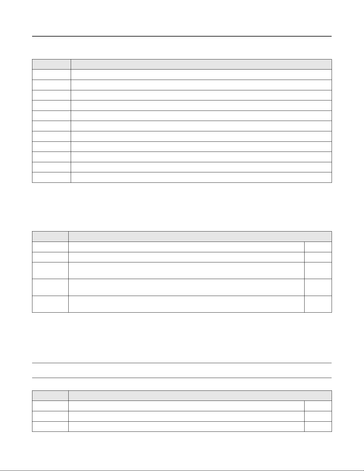
Table 47: Rosemount 8705-M flange rating (continued)
Code Product description
E EN 1092-1, PN16
F EN 1092-1, PN25
H EN 1092-1, PN40
(2)
K
(2)
L
(3)
P
(3)
R
(4)
T
(5)
U
(5)
W
(5)
Y
Not available with lining protectors.
(1)
Not available with PFA (A) liner; not available with lining protectors.
(2)
Available line sizes ½-in. to 24-in. (15 mm to 600 mm); not available with lining protectors.
(3)
Available line sizes ½-in. to 16-in. (15 mm to 400 mm); not available with lining protectors.
(4)
Available in 2-in. to 4-in. (50 mm to 100 mm) and 6-in. to 24-in. (150 mm to 600 mm) line sizes; not available with lining protectors.
(5)
AS2129, Table D
AS2129, Table E
JIS B 2220, 10K
JIS B 2220, 20K
JIS B 2220, 40K
AS4087, PN16
AS4087, PN21
AS4087, PN35
May 2019
Table 48: Rosemount 8705-M housing configuration
Code Product description
(1)(2)
W0
M0
M1
(3)
(3)(4)
Sealed, Welded Housing with Legacy Terminal Block ★
Sealed, Welded Housing with Field Replaceable Terminal Block/Socket Module ★
Sealed, Welded Housing with Pressure Relief Port and Field Replaceable Terminal Block/Socket
Module
(3)
M2
Sealed, Welded Housing with Sealed Electrode Compartments and Field Replaceable Terminal Block/
Socket Module
(3)
M4
Sealed, Welded Housing with Sealed Electrode Compartments with Cap and Port with Field
Replaceable Terminal Block/Socket Module
Available for Ordinary Locations or "EN" NEPSI China Domestic Only.
(1)
Consult Product Data Sheet 00813-0100-4727 for technical details.
(2)
Consult Technical Support for use with Ordinary Locations.
(3)
Pressure relief valve must be installed appropriately to maintain the approvals on the meter. Recovery piping diameter must not be smaller than
(4)
M6 to avoid building pressure after the valve.
Options
Note
These are not required, but they must be included in the model number if desired.
Table 49: Rosemount 8705-M hazardous area certifications
Code Description
(1)
-
Ordinary Locations - (no code required) ★
N5 US Approvals, Class I Div 2, Non-Incendive with I.S. Electrodes; and Dust ★
(2)
K5
US Approvals, Class I Div 1, Explosion proof with I.S. Electrodes; and Dust ★
20 www.rosemount.com

May 2019
Table 49: Rosemount 8705-M hazardous area certifications (continued)
Code Description
N6 Canadian Approvals, Class I Div 2, Non-Incendive with I.S. Electrodes; and Dust ★
K6 US/Canadian Approvals, Increased Safety with I.S. Electrodes; and Dust ★
(2)
KU
US Approvals, Class I Div 1, Explosion proof with I.S. Electrodes; and Dust ★
ND ATEX Dust ★
N1 ATEX Non-Sparking with I.S. Electrodes; ATEX Dust ★
K1 ATEX Increased Safety with I.S. Electrodes; ATEX Dust ★
NF IECEx Dust ★
N7 IECEx Non-Sparking with I.S. Electrodes; IECEx Dust ★
K7 IECEx Increased Safety with I.S. Electrodes; IECEx Dust ★
N8 EAC Non-Sparking with I.S. Electrodes; EAC Dust ★
K8 EAC Increased Safety with I.S. Electrodes; EAC Dust ★
N2 INMETRO Non-Sparking with I.S. Electrodes; INMETRO Dust ★
K2 INMETRO Increased Safety with I.S. Electrodes; INMETRO Dust ★
N3 NEPSI Non-Sparking with I.S. Electrodes; NEPSI Dust ★
K3 NEPSI Increased Safety with I.S. Electrodes; NEPSI Dust ★
K9 KTL Flameproof with Increased Safety, KTL Dust ★
Labeled with CSA(C/US), CE, C-tick and EAC.
(1)
Available line sizes ½-in. to 12-in. (15 mm to 300 mm).
(2)
Table 50: Rosemount 8705-M certifications
Code Product description
CR Canadian Registration Number (CRN) Certification
PD Pressure Equipment Directive Certification (PED)
(1)
DW
Available liners PTFE (T) all line sizes or Polyurethane (P) 4-in. or larger; electrode materials 316L SST (S) or Ni-Alloy 276 (H).
(1)
NSF Drinking Water Certification
Table 51: Rosemount 8705-M grounding rings
Code Product description
(1)
G1 (2) 316L SST Ground Rings
G2 (2) Nickel Alloy 276 (UNS N10276) Ground Rings
G3 (2) Titanium Ground Rings
G4 (2) Tantalum Ground Rings
G5 (1) 316L SST Ground Ring
G6 (1) Nickel Alloy 276 (UNS N10276) Ground Ring
G7 (1) Titanium Ground Ring
G8 (1) Tantalum Ground Ring
Grounding Rings and Lining Protectors provide the same process reference function.
(1)
www.rosemount.com 21

Table 52: Rosemount 8705-M lining protectors
Code Product description
(1)
L1 (2) 316L SST Lining Protectors
L2 (2) Nickel Alloy 276 (UNS N10276) Lining Protectors
L3 (2) Titanium Lining Protectors
L5 (1) 316L SST Lining Protector
L6 (1) Nickel Alloy 276 (UNS N10276) Lining Protector
L7 (1) Titanium Lining Protector
Grounding Rings and Lining Protectors provide the same process reference function.
(1)
Table 53: Rosemount 8705-M miscellaneous
Code Product description
B3 Integral Mount with 8732EM Transmitter
(1)
D1
High Accuracy Calibration (0.15% of rate for matched sensor and transmitter).
D3 Low Power Calibration
(2)
H1
H2
J1
P05
P10
SH
SJ
(3)
(4)
(5)
(6)
(7)
(7)
Lay-length matching 8701 using spool piece/spacer
Lay-length matching 8701
M20–1.5 Conduit Entries
5 Point Calibration Verification
10 Point Calibration Verification
316 SST Coil Housing and Remote Junction Box
316 SST Remote Junction Box
May 2019
The high accuracy calibration requires a matched transmitter. It is only available when ordered with a transmitter. Spare or replacement orders
(1)
are not available with the D1 option.
Available line sizes ½ -in. to 12-in. (15 mm to 300 mm).
(2)
Available in sensor line sizes ½ -in. to 16-in. (15 mm to 400 mm).
(3)
M20 conduit adapters are supplied for Ordinary Locations and US/Canadian Approvals N5, N6, K5 and KU.
(4)
Available for: ½-in. to 24-in. (15 mm to 600 mm) Velocities 1, 3, 5, 7, 10 ft/s; 30-in. (700 mm) Velocities 1, 3, 5, 7, 9.5 ft/s; 36-in. (900 mm)
(5)
Velocities 1, 2, 3, 5, 6.5 ft/s.
Available for: ½-in. to 24-in. (15 mm to 600 mm) Velocities 1, 2, 3, 4, 5, 6, 7, 8, 9, 10 ft/s; 30-in. to 36-in. (700 mm to 900 mm) not available.
(6)
Not available with US/Canadian Approvals N5, K5, N6, or KU.
(7)
Table 54: Rosemount 8705-M paint
Model Product description ★
V1 Coal Tar Paint
V2 Offshore/Near Shore Marine Paint (3 layer epoxy)
Table 55: Rosemount 8705-M quality certificates
Code Product description ★
Q4 Calibration Certificate per ISO 10474 3.1B/EN 10204 3.1
Q5 Hydrostatic Test Certificate
Q8 Material Traceability per ISO 10474 3.1B/EN 10204 3.1
22 www.rosemount.com
ASME Class 150
ASME Class 300
ASME Class 600 Derated
ASME Class 600 Full Rated
ASME Class 900
AS2129 Table D
AS2129 Table E
AS4087 PN16
AS4087 PN21
AS4087 PN35
May 2019
Table 55: Rosemount 8705-M quality certificates (continued)
Code Product description ★
Q25 Certificate of Compliance to NACE MR0103
Q66 Weld Procedure Package (Weld Map, Weld Procedure Specification, Weld Procedure Qualification Record,
Welder Performance Qualification)
Q70 NDE Weld Examination Inspection Certificate, ISO 10474 3.1B
(1)
Q71
NDE Weld Examination Inspection Certificate, ISO 10474 3.1B with images
Q76 Positive Material Identification (PMI) on flanges and pipe, per ASTM E1476-97
Weld-Neck only.
(1)
Table 56: Rosemount 8705-M witness inspection
Code Product description ★
WG Witness Inspection
Slip-on flanges
Table 57: Slip on flange options by line size
Flange code and rating
1 2 3 6 7 9 D E F H K L P R T U W Y
Size
code
MSS-SP44 Class 150 (30", 36")
005 ★ ★ ★ ★ ★ ★ ★ ★ ★ ★
010 ★ ★ ★ ★ ★ ★ ★ ★ ★ ★ ★
015 ★ ★ ★ ★ ★ ★ ★ ★ ★ ★ ★
020 ★ ★ ★ ★ ★ ★ ★ ★ ★ ★ ★ ★ ★ ★ ★
025 ★ ★ ★ ★ ★ ★ ★ ★ ★ ★ ★ ★ ★ ★ ★
030 ★ ★ ★ ★ ★ ★ ★ ★ ★ ★ ★ ★ ★ ★ ★
040 ★ ★ ★ ★ ★ ★ ★ ★ ★ ★ ★ ★ ★ ★ ★
050 ★ ★ ★ ★ ★ ★ ★ ★ ★ ★ ★ ★
060 ★ ★ ★ ★ ★ ★ ★ ★ ★ ★ ★ ★ ★ ★ ★ ★
080 ★ ★ ★ ★ ★ ★ ★ ★ ★ ★ ★ ★ ★ ★ ★ ★ ★
100 ★ ★ ★ ★ ★ ★ ★ ★ ★ ★ ★ ★ ★ ★ ★ ★ ★
120 ★ ★ ★ ★ ★ ★ ★ ★ ★ ★ ★ ★ ★ ★ ★ ★ ★
140 ★ ★ ★ ★ ★ ★ ★ ★ ★ ★ ★ ★ ★ ★ ★ ★ ★
160 ★ ★ ★ ★ ★ ★ ★ ★ ★ ★ ★ ★ ★ ★ ★ ★ ★
www.rosemount.com 23

ASME Class 150
ASME Class 300
ASME Class 600 Derated
ASME Class 600 Full Rated
ASME Class 900
AS2129 Table D
AS2129 Table E
AS4087 PN16
AS4087 PN21
AS4087 PN35
ASME Class 150
ASME Class 150 (30", 36")
ASME Class 300
ASME Class 600 Derated
ASME Class 600 Full Rated
ASME Class 900
ASME Class 1500
ASME Class 2500
May 2019
Table 57: Slip on flange options by line size (continued)
Flange code and rating
1 2 3 6 7 9 D E F H K L P R T U W Y
Size
code
MSS-SP44 Class 150 (30", 36")
180 ★ ★ ★ ★ ★ ★ ★ ★ ★ ★ ★ ★ ★ ★ ★ ★
200 ★ ★ ★ ★ ★ ★ ★ ★ ★ ★ ★ ★ ★ ★ ★ ★
240 ★ ★ ★ ★ ★ ★ ★ ★ ★ ★ ★ ★ ★ ★ ★
300 ★
360 ★
AWWA Class D
(1)
(1)
★ ★ ★ ★ ★ ★ ★
(1)
★ ★ ★ ★ ★ ★ ★ ★ ★
Weld neck flanges
Table 58: Weld neck flange options by line size
Flange code and rating
1 2 3 6 7 9 D E F H M N
Size code
005 ★ ★ ★
010 ★ ★ ★ ★ ★ ★ ★
015 ★ ★ ★ ★ ★ ★ ★ ★
020 ★ ★ ★ ★ ★ ★ ★ ★
025 ★ ★
030 ★ ★ ★ ★ ★ ★ ★ ★
040 ★ ★ ★ ★ ★ ★ ★ ★ ★
050
060 ★ ★ ★ ★ ★ ★ ★ ★ ★ ★
080 ★ ★ ★ ★ ★ ★ ★ ★ ★ ★ ★
100 ★ ★ ★ ★ ★ ★ ★ ★ ★ ★
120 ★ ★ ★ ★ ★ ★ ★ ★ ★ ★
24 www.rosemount.com
ASME Class 150
ASME Class 150 (30", 36")
ASME Class 300
ASME Class 600 Derated
ASME Class 600 Full Rated
ASME Class 900
ASME Class 1500
ASME Class 2500
May 2019
Table 58: Weld neck flange options by line size (continued)
Flange code and rating
1 2 3 6 7 9 D E F H M N
Size code
140 ★ ★ ★ ★ ★ ★ ★ ★ ★
160 ★ ★ ★ ★ ★ ★ ★ ★ ★
180 ★ ★ ★ ★ ★ ★ ★ ★ ★
200 ★ ★ ★ ★ ★ ★ ★ ★ ★
240 ★ ★ ★ ★ ★ ★ ★ ★
300 ★
360 ★
(1)
(1)
(1)
★
(1)
★
★ ★ ★
ASME B16.47 Series A.
(1)
www.rosemount.com 25
May 2019
Rosemount 8711-M/L Wafer Sensors
The flangeless design of the wafer sensor makes it an economical, compact, and lightweight alternative to flanged magnetic
flowmeters. Alignment spacers are provided with every 8711-M/L which help center the sensor in the process line simplifying
installation.
Note
The starred (★) offerings represent the most common options, and should be selected for best delivery.
Model code structure
Example model code with one selection out of each category: 8711 S S A 040 L 1 K5 G5 MK3 PD P05 Q4 WG
Table 59: Requirements - select one from each available choice
Example code Category
8711 Base model—Rosemount Wafer Sensors.
S Lining material (Table 61)
S Electrode material (Table 62)
A Electrode type (Table 63)
040 Line size (Table 64)
L Transmitter mounting configuration (Table 65)
1 Mating pipe flange pressure rating (Table 66)
Table 60: Options - select only as needed
Example code Category
K5 Hazardous area certifications (Table 67)
G5 Grounding rings (Table 68)
MK3 Mounting hardware (Table 69)
PD Certifications (Table 70)
P05 Other options (Table 71)
Q4 Quality certificates (Table 72)
WG Witness inspection (Table 71)
26 www.rosemount.com
May 2019
Requirements
Table 61: Rosemount 8711-M/L Wafer Sensor lining material
Code Product description
S PTFE ★
F ETFE
Table 62: Rosemount 8711-M/L Wafer Sensor electrode material
Code Product description
S 316L Stainless Steel ★
H Nickel Alloy 276 (UNS N10276) ★
T Tantalum ★
P 80% Platinum - 20% Iridium ★
N Titanium ★
Table 63: Rosemount 8711-M/L Wafer Sensor electrode type
Code Product description
A 2 Measurement Electrodes ★
E 2 Measurement Electrodes plus 1 Reference Electrode
B 2 Bulletnose Measurement Electrodes
F 2 Measurement Bulletnose Electrodes plus 1 Reference Bulletnose Electrode
Table 64: Rosemount 8711-M/L Wafer Sensor line size
Code Product description
015 1½-in. (40 mm)
020 2-in. (50 mm)
030 3-in. (80 mm)
040 4-in. (100 mm)
060 6-in. (150 mm)
080 8-in. (200 mm)
Table 65: Rosemount 8711-M/L Wafer Sensor - transmitter mounting configuration
Code Product description
(1) (2)
R
U
(1) (2)
Remote Mount with Legacy Terminal Block
Integral Mount IMS Cable Assembly for use with an 8732EM Transmitter
L Remote Mount with Field Replaceable Terminal Block
(3)
M
Available for Ordinary Locations or "EN" NEPSI China Domestic only.
(1)
Reference Product Data Sheet 00813-0100-4727 for technical details.
(2)
Consult Technical Support for use with Ordinary Locations.
(3)
Integral Mount Socket Module/Direct Lead Assembly for use with an 8732EM Transmitter
www.rosemount.com 27
Table 66: Rosemount 8711-M/L Wafer Sensor mating pipe flange pressure rating
Code Product description
Note
Includes three alignment spacers (where applicable)
1 ASME, Class 150
3 ASME, Class 300
D EN1092-1, PN10
E EN1092-1, Flange Rating up to PN16
F EN1092-1, Flange Rating up to PN25
H EN1092-1, Flange Rating up to PN40
P JIS B2220, 10K
R JIS B2220, 20K
U AS4087, PN16
W AS4087, PN21
Y AS4087, PN35
May 2019
Options
Note
These are not required, but they must be included in the model number if desired.
Table 67: Rosemount 8711-M/L Wafer Sensor hazardous area certifications
Code Description
(1)
-
N5 US Approvals, Class I Div 2, Non-Incendive with I.S. Electrodes; and Dust ★
K5 US Approvals, Class I Div 1, Explosion proof with I.S. Electrodes; and Dust ★
N6 Canadian Approvals, Class I Div 2, Non-Incendive with I.S. Electrodes; and Dust ★
K6 US/Canadian Approvals, Increased Safety with I.S. Electrodes; and Dust ★
KU US Approvals, Class I Div 1, Explosion proof with I.S. Electrodes; and Dust ★
ND ATEX Dust ★
N1 ATEX Non-Sparking with I.S. Electrodes; ATEX Dust ★
K1 ATEX Increased Safety with I.S. Electrodes; ATEX Dust ★
NF IECEx Dust ★
K9 KTL Flameproof with Increased Safety, KTL Dust ★
N7 IECEx Non-Sparking with I.S. Electrodes; IECEx Dust ★
Ordinary Locations - (no code required) ★
K7 IECEx Increased Safety with I.S. Electrodes; IECEx Dust ★
N8 EAC Non-Sparking with I.S. Electrodes; EAC Dust ★
K8 EAC Increased Safety with I.S. Electrodes; EAC Dust ★
N2 INMETRO Non-Sparking with I.S. Electrodes; INMETRO Dust ★
K2 INMETRO Increased Safety with I.S. Electrodes; INMETRO Dust ★
28 www.rosemount.com
May 2019
Table 67: Rosemount 8711-M/L Wafer Sensor hazardous area certifications (continued)
Code Description
N3 NEPSI Non-Sparking with I.S. Electrodes; NEPSI Dust ★
K3 NEPSI Increased Safety with I.S. Electrodes; NEPSI Dust ★
Labeled with CSA(C/US), CE, C-tick and EAC.
(1)
Table 68: Rosemount 8711-M/L Wafer Sensor grounding rings
Code Product description
(1)
G1 (2) 316L SST Ground Rings
G2 (2) Nickel Alloy 276 (UNS N10276) Ground Rings
G3 (2) Titanium Ground Rings
G4 (2) Tantalum Ground Rings
G5 (1) 316L SST Ground Ring
G6 (1) Nickel Alloy 276 (UNS N10276) Ground Ring
G7 (1) Titanium Ground Ring
G8 (1) Tantalum Ground Ring
Best practice to use (2) two ground rings with wafer design.
(1)
Table 69: Rosemount 8711-M/L Wafer Sensor mounting hardware
Code Product description
MK2 Carbon Steel mounting Studs & Nuts Kit
MK3 316 SST mounting Studs & Nuts Kit
Table 70: Rosemount 8711-M/L Wafer Sensor certifications
Code Product description
PD Pressure Equipment Directive Certification (PED, per 97/23/EC)
(1)
DW
Available liner PTFE (T) and electrode materials 316L SST (S) or Ni-Alloy 276 (H).
(1)
NSF Drinking Water Certification
Table 71: Rosemount 8711-M/L Wafer Sensor other options
Code Product description
(1)
D1
J1
SJ
P05
P10
(2)
(3)
(4)
(5)
High Accuracy Calibration (0.15% of rate for matched sensor and transmitter)
M20–1.5 Conduit Entries
316 SST Remote Junction Box
5 Point Calibration Verification
10 Point Calibration Verification
The high accuracy calibration requires a matched transmitter. It is only available when ordered with a transmitter. Spare or replacement orders
(1)
are not available with the D1 option.
M20 conduit adapters are supplied for Ordinary Locations and US/Canadian Approvals N5, N6, K5 and KU.
(2)
Not available with US/Canadian Approvals N5, N6, K5, or KU.
(3)
Available for: 1/2-in. to 8-in. (15 to 200 mm) Velocities 1, 3, 5, 7, 10 ft/s.
(4)
Available for: 1/2-in. to 8-in. (15 to 200 mm) Velocities 1, 2, 3, 4, 5, 6, 7, 8, 9, 10 ft/s.
(5)
www.rosemount.com 29

Table 72: Rosemount 8711-M/L Wafer Sensor quality certificates
Code Product description
Q4 Calibration Certificate per ISO 10474 3.1B/ EN 10204 3.1
Q5 Hydrostatic Test Certificate
Q8 Material Traceability per ISO 10474 3.1B / EN 10204 3.1
Q25 Certificate of Compliance to NACE MR0103
(1)
Q66
Weld Procedure Package (Weld Map, Weld Procedure Specification, Weld Procedure Qualification Record,
Welder Performance Qualification)
Q70 NDE Weld Examination Inspection Certificate, ISO 10474 3.1B
Q76 Positive Material Identification (PMI) on Pipe, per ASTM E1476-97
Available on 6- and 8-in. only.
(1)
Table 73: Rosemount 8711-M/L Wafer Sensor witness inspection
Code Product description
WG Witness Inspection
May 2019
30 www.rosemount.com
 Loading...