

Page 1
Rosemount™ 8600 Series Vortex Flowmeter
Reference Manual
00809-0100-4860, Rev BD
October 2016
Page 2

Page 3

Reference Manual
00809-0100-4860, Rev BD
Contents
1Section 1: Introduction
2Section 2: Configuration
Table of Contents
October2016
1.1 How to use this manual. . . . . . . . . . . . . . . . . . . . . . . . . . . . . . . . . . . . . . . . . . . . . . . . . 1
1.2 Safety messages. . . . . . . . . . . . . . . . . . . . . . . . . . . . . . . . . . . . . . . . . . . . . . . . . . . . . . .1
1.3 System description . . . . . . . . . . . . . . . . . . . . . . . . . . . . . . . . . . . . . . . . . . . . . . . . . . . . 1
2.1 Review . . . . . . . . . . . . . . . . . . . . . . . . . . . . . . . . . . . . . . . . . . . . . . . . . . . . . . . . . . . . . . .3
2.2 Process variables . . . . . . . . . . . . . . . . . . . . . . . . . . . . . . . . . . . . . . . . . . . . . . . . . . . . . . 3
2.2.1 Primary Variable (PV) . . . . . . . . . . . . . . . . . . . . . . . . . . . . . . . . . . . . . . . . . . . 4
2.2.2 PV% of range. . . . . . . . . . . . . . . . . . . . . . . . . . . . . . . . . . . . . . . . . . . . . . . . . . . 4
2.2.3 Analog output . . . . . . . . . . . . . . . . . . . . . . . . . . . . . . . . . . . . . . . . . . . . . . . . . 4
2.2.4 View other variables . . . . . . . . . . . . . . . . . . . . . . . . . . . . . . . . . . . . . . . . . . . . 4
2.3 Basic setup. . . . . . . . . . . . . . . . . . . . . . . . . . . . . . . . . . . . . . . . . . . . . . . . . . . . . . . . . . .12
2.3.1 Tag . . . . . . . . . . . . . . . . . . . . . . . . . . . . . . . . . . . . . . . . . . . . . . . . . . . . . . . . . .12
2.3.2 Process configuration . . . . . . . . . . . . . . . . . . . . . . . . . . . . . . . . . . . . . . . . . .12
2.3.3 Reference K-factor. . . . . . . . . . . . . . . . . . . . . . . . . . . . . . . . . . . . . . . . . . . . .15
2.3.4 Flange type . . . . . . . . . . . . . . . . . . . . . . . . . . . . . . . . . . . . . . . . . . . . . . . . . . . 15
2.3.5 Mating pipe ID (Inside Diameter) . . . . . . . . . . . . . . . . . . . . . . . . . . . . . . . .16
2.3.6 Variable mapping . . . . . . . . . . . . . . . . . . . . . . . . . . . . . . . . . . . . . . . . . . . . .16
2.3.7 PV units . . . . . . . . . . . . . . . . . . . . . . . . . . . . . . . . . . . . . . . . . . . . . . . . . . . . . .17
2.3.8 Range values. . . . . . . . . . . . . . . . . . . . . . . . . . . . . . . . . . . . . . . . . . . . . . . . . .17
2.3.9 PV damping . . . . . . . . . . . . . . . . . . . . . . . . . . . . . . . . . . . . . . . . . . . . . . . . . .17
2.3.10 Auto adjust filter . . . . . . . . . . . . . . . . . . . . . . . . . . . . . . . . . . . . . . . . . . . . . . 18
3Section 3: Installation
3.1 Safety messages. . . . . . . . . . . . . . . . . . . . . . . . . . . . . . . . . . . . . . . . . . . . . . . . . . . . . .21
3.2 Commissioning. . . . . . . . . . . . . . . . . . . . . . . . . . . . . . . . . . . . . . . . . . . . . . . . . . . . . . .23
3.2.1 General considerations. . . . . . . . . . . . . . . . . . . . . . . . . . . . . . . . . . . . . . . . .23
3.2.2 Flowmeter sizing . . . . . . . . . . . . . . . . . . . . . . . . . . . . . . . . . . . . . . . . . . . . . .23
3.2.3 Flowmeter orientation . . . . . . . . . . . . . . . . . . . . . . . . . . . . . . . . . . . . . . . . . 23
3.2.4 Wetted material selection . . . . . . . . . . . . . . . . . . . . . . . . . . . . . . . . . . . . . .26
3.2.5 Environmental considerations. . . . . . . . . . . . . . . . . . . . . . . . . . . . . . . . . . . 26
3.3 Hazardous locations . . . . . . . . . . . . . . . . . . . . . . . . . . . . . . . . . . . . . . . . . . . . . . . . . .27
Table of Contents
3.4 Hardware configuration . . . . . . . . . . . . . . . . . . . . . . . . . . . . . . . . . . . . . . . . . . . . . . .27
iii
Page 4

Table of Contents
October 2016
Reference Manual
00809-0100-4860, Rev BD
3.4.1 Failure mode vs. saturation output values . . . . . . . . . . . . . . . . . . . . . . . . 28
3.4.2 LCD indicator option . . . . . . . . . . . . . . . . . . . . . . . . . . . . . . . . . . . . . . . . . . .28
3.5 Meter body installation tasks . . . . . . . . . . . . . . . . . . . . . . . . . . . . . . . . . . . . . . . . . . .29
3.5.1 Handling . . . . . . . . . . . . . . . . . . . . . . . . . . . . . . . . . . . . . . . . . . . . . . . . . . . . .29
3.5.2 Flow direction. . . . . . . . . . . . . . . . . . . . . . . . . . . . . . . . . . . . . . . . . . . . . . . . .30
3.5.3 Gaskets . . . . . . . . . . . . . . . . . . . . . . . . . . . . . . . . . . . . . . . . . . . . . . . . . . . . . .30
3.5.4 Flange bolts. . . . . . . . . . . . . . . . . . . . . . . . . . . . . . . . . . . . . . . . . . . . . . . . . . . 31
3.5.5 Flanged-style flowmeter mounting . . . . . . . . . . . . . . . . . . . . . . . . . . . . . . 31
3.5.6 Flowmeter grounding . . . . . . . . . . . . . . . . . . . . . . . . . . . . . . . . . . . . . . . . . . 32
3.6 Electronics considerations . . . . . . . . . . . . . . . . . . . . . . . . . . . . . . . . . . . . . . . . . . . . .32
3.6.1 High-Temperature installations . . . . . . . . . . . . . . . . . . . . . . . . . . . . . . . . .32
3.6.2 Conduit connections. . . . . . . . . . . . . . . . . . . . . . . . . . . . . . . . . . . . . . . . . . .33
3.6.3 High-Point installation . . . . . . . . . . . . . . . . . . . . . . . . . . . . . . . . . . . . . . . . .33
3.6.4 Cable gland . . . . . . . . . . . . . . . . . . . . . . . . . . . . . . . . . . . . . . . . . . . . . . . . . . .33
3.6.5 Grounding the transmitter case . . . . . . . . . . . . . . . . . . . . . . . . . . . . . . . . .34
3.6.6 Wiring procedure. . . . . . . . . . . . . . . . . . . . . . . . . . . . . . . . . . . . . . . . . . . . . . 34
3.6.7 Remote electronics . . . . . . . . . . . . . . . . . . . . . . . . . . . . . . . . . . . . . . . . . . . . 39
3.6.8 Calibration. . . . . . . . . . . . . . . . . . . . . . . . . . . . . . . . . . . . . . . . . . . . . . . . . . . . 41
3.7 Software configuration . . . . . . . . . . . . . . . . . . . . . . . . . . . . . . . . . . . . . . . . . . . . . . . .41
3.7.1 Installing the indicator . . . . . . . . . . . . . . . . . . . . . . . . . . . . . . . . . . . . . . . . . 43
3.8 Transient protection . . . . . . . . . . . . . . . . . . . . . . . . . . . . . . . . . . . . . . . . . . . . . . . . . .44
3.8.1 Installing the Transient Protector . . . . . . . . . . . . . . . . . . . . . . . . . . . . . . . .44
4Section 4: Operation
4.1 Diagnostics/service . . . . . . . . . . . . . . . . . . . . . . . . . . . . . . . . . . . . . . . . . . . . . . . . . . .47
4.1.1 Test/status . . . . . . . . . . . . . . . . . . . . . . . . . . . . . . . . . . . . . . . . . . . . . . . . . . . 47
4.1.2 Loop test . . . . . . . . . . . . . . . . . . . . . . . . . . . . . . . . . . . . . . . . . . . . . . . . . . . . .48
4.1.3 Pulse output test . . . . . . . . . . . . . . . . . . . . . . . . . . . . . . . . . . . . . . . . . . . . . .48
4.1.4 Flow simulation . . . . . . . . . . . . . . . . . . . . . . . . . . . . . . . . . . . . . . . . . . . . . . .49
4.1.5 D/A trim(Digital-to-Analog Trim) . . . . . . . . . . . . . . . . . . . . . . . . . . . . . . . . 50
4.1.6 Scaled D/A trim . . . . . . . . . . . . . . . . . . . . . . . . . . . . . . . . . . . . . . . . . . . . . . . 50
4.1.7 Shed freq at URV . . . . . . . . . . . . . . . . . . . . . . . . . . . . . . . . . . . . . . . . . . . . . .51
4.2 Advanced functionality . . . . . . . . . . . . . . . . . . . . . . . . . . . . . . . . . . . . . . . . . . . . . . . .51
4.3 Detailed set-up . . . . . . . . . . . . . . . . . . . . . . . . . . . . . . . . . . . . . . . . . . . . . . . . . . . . . . .51
4.3.1 Characterize meter . . . . . . . . . . . . . . . . . . . . . . . . . . . . . . . . . . . . . . . . . . . .51
4.3.2 Configure outputs . . . . . . . . . . . . . . . . . . . . . . . . . . . . . . . . . . . . . . . . . . . . . 53
4.3.3 Signal processing. . . . . . . . . . . . . . . . . . . . . . . . . . . . . . . . . . . . . . . . . . . . . . 61
4.3.4 Device information . . . . . . . . . . . . . . . . . . . . . . . . . . . . . . . . . . . . . . . . . . . .64
iv
Table of Contents
Page 5

Reference Manual
00809-0100-4860, Rev BD
5Section 5: Troubleshooting
Table of Contents
October2016
5.1 Safety messages. . . . . . . . . . . . . . . . . . . . . . . . . . . . . . . . . . . . . . . . . . . . . . . . . . . . . .67
5.2 Troubleshooting tables. . . . . . . . . . . . . . . . . . . . . . . . . . . . . . . . . . . . . . . . . . . . . . . .68
5.3 Advanced troubleshooting. . . . . . . . . . . . . . . . . . . . . . . . . . . . . . . . . . . . . . . . . . . . .69
5.3.1 Diagnostic messages . . . . . . . . . . . . . . . . . . . . . . . . . . . . . . . . . . . . . . . . . .69
5.3.2 Electronics test points. . . . . . . . . . . . . . . . . . . . . . . . . . . . . . . . . . . . . . . . . . 71
5.3.3 TP1 . . . . . . . . . . . . . . . . . . . . . . . . . . . . . . . . . . . . . . . . . . . . . . . . . . . . . . . . . . 72
5.4 Diagnostic messages on LCD . . . . . . . . . . . . . . . . . . . . . . . . . . . . . . . . . . . . . . . . . . .73
5.5 Testing procedures . . . . . . . . . . . . . . . . . . . . . . . . . . . . . . . . . . . . . . . . . . . . . . . . . . .75
5.6 Hardware replacement . . . . . . . . . . . . . . . . . . . . . . . . . . . . . . . . . . . . . . . . . . . . . . . .75
5.6.1 Replacing the terminal block in the housing . . . . . . . . . . . . . . . . . . . . . . 76
5.6.2 Replacing the electronics boards . . . . . . . . . . . . . . . . . . . . . . . . . . . . . . . .77
5.6.3 Replacing the electronics housing . . . . . . . . . . . . . . . . . . . . . . . . . . . . . . .79
5.6.4 Replacing the sensor . . . . . . . . . . . . . . . . . . . . . . . . . . . . . . . . . . . . . . . . . . .80
5.6.5 Remote electronics procedure . . . . . . . . . . . . . . . . . . . . . . . . . . . . . . . . . .83
5.6.6 Coaxial cable at the electronics housing . . . . . . . . . . . . . . . . . . . . . . . . . . 85
5.6.7 Changing the housing orientation . . . . . . . . . . . . . . . . . . . . . . . . . . . . . . . 87
5.6.8 Temperature sensor replacement (MTA option only). . . . . . . . . . . . . . . 87
5.7 Return of material . . . . . . . . . . . . . . . . . . . . . . . . . . . . . . . . . . . . . . . . . . . . . . . . . . . .88
AAppendix A: Specifications and Reference Data
A.1 Specifications . . . . . . . . . . . . . . . . . . . . . . . . . . . . . . . . . . . . . . . . . . . . . . . . . . . . . . . .89
A.2 Functional specifications . . . . . . . . . . . . . . . . . . . . . . . . . . . . . . . . . . . . . . . . . . . . . .89
A.3 Typical flow ranges . . . . . . . . . . . . . . . . . . . . . . . . . . . . . . . . . . . . . . . . . . . . . . . . . . .92
A.4 Performance specifications . . . . . . . . . . . . . . . . . . . . . . . . . . . . . . . . . . . . . . . . . . . .97
A.4.1 Flow accuracy. . . . . . . . . . . . . . . . . . . . . . . . . . . . . . . . . . . . . . . . . . . . . . . . .97
A.5 Physical specifications. . . . . . . . . . . . . . . . . . . . . . . . . . . . . . . . . . . . . . . . . . . . . . . . .98
A.6 Dimensional drawings. . . . . . . . . . . . . . . . . . . . . . . . . . . . . . . . . . . . . . . . . . . . . . . 100
BAppendix B: Product Certifications
B.1 Overview . . . . . . . . . . . . . . . . . . . . . . . . . . . . . . . . . . . . . . . . . . . . . . . . . . . . . . . . . . 105
B.2 Product certifications . . . . . . . . . . . . . . . . . . . . . . . . . . . . . . . . . . . . . . . . . . . . . . . 105
B.2.1 Approved manufacturing locations . . . . . . . . . . . . . . . . . . . . . . . . . . . . .105
B.2.2 International certifications (IECEx) . . . . . . . . . . . . . . . . . . . . . . . . . . . . . .105
B.2.3 Chinese certifications (NEPSI) . . . . . . . . . . . . . . . . . . . . . . . . . . . . . . . . . .106
B.2.4 European certifications (ATEX) . . . . . . . . . . . . . . . . . . . . . . . . . . . . . . . . .108
Table of Contents
B.2.5 EurAsian Conformity (EAC) . . . . . . . . . . . . . . . . . . . . . . . . . . . . . . . . . . . .109
B.2.6 Canadian Standards Association (CSA) . . . . . . . . . . . . . . . . . . . . . . . . . .109
v
Page 6

Table of Contents
October 2016
CAppendix C: Electronics Verification
DAppendix D: HART® Menu Tree
Reference Manual
00809-0100-4860, Rev BD
C.1 Safety messages. . . . . . . . . . . . . . . . . . . . . . . . . . . . . . . . . . . . . . . . . . . . . . . . . . . . 111
C.2 Electronics verification . . . . . . . . . . . . . . . . . . . . . . . . . . . . . . . . . . . . . . . . . . . . . . 112
C.2.1 Electronics verification using flow simulation mode. . . . . . . . . . . . . . .112
C.2.2 Fixed flow rate simulation . . . . . . . . . . . . . . . . . . . . . . . . . . . . . . . . . . . . .112
C.2.3 Varying flow rate simulation . . . . . . . . . . . . . . . . . . . . . . . . . . . . . . . . . . .112
C.2.4 Electronics verification using an external frequency generator . . . . .113
C.2.5 Calculating output variables with known input frequency . . . . . . . . .114
C.3 Examples . . . . . . . . . . . . . . . . . . . . . . . . . . . . . . . . . . . . . . . . . . . . . . . . . . . . . . . . . . 116
C.3.1 English units . . . . . . . . . . . . . . . . . . . . . . . . . . . . . . . . . . . . . . . . . . . . . . . . .116
C.3.2 SI units . . . . . . . . . . . . . . . . . . . . . . . . . . . . . . . . . . . . . . . . . . . . . . . . . . . . . .120
D.1 Overview . . . . . . . . . . . . . . . . . . . . . . . . . . . . . . . . . . . . . . . . . . . . . . . . . . . . . . . . . . 123
vi
Table of Contents
Page 7

Reference Manual
NOTICE
00809-0100-4860, Rev BD
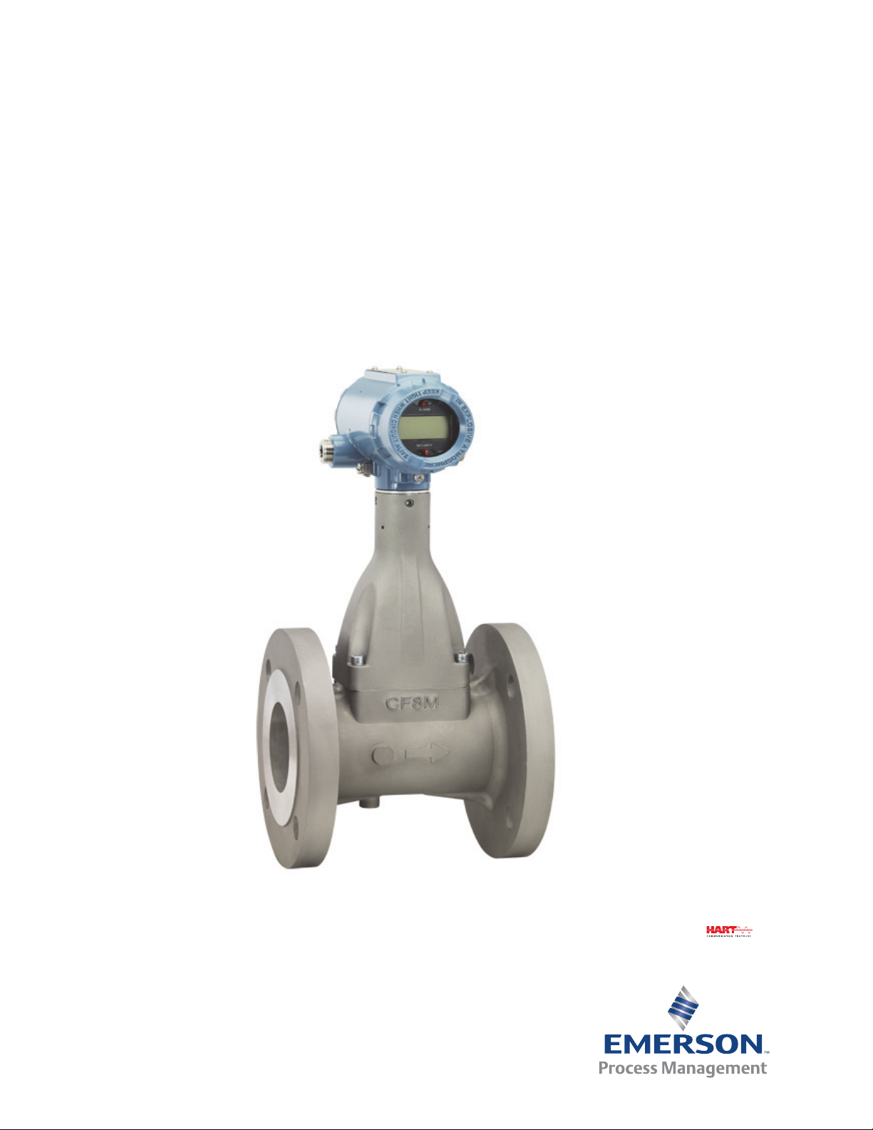
Rosemount™ 8600D
Smart Vortex Flowmeter
Read this manual before working with the product. For personal and system safety, and for
optimum product performance, make sure you thoroughly understand the contents
before installing, using, or maintaining this product.
Within the United States, Emerson Process Management has two toll-free assistance
numbers:
Customer Central
Technical support, quoting, and order-related questions.
1-800-999-9307 (7:00 am to 7:00 pm CST)
North American Response Center
Equipment service needs.
1-800-654-7768 (24 hours—includes Canada)
Outside of the United States, contact your local Emerson Process Management
representative.
Title Page
October 2016
The products described in this document are NOT designed for nuclear-qualified
applications. Using non-nuclear qualified products in applications that require
nuclear-qualified hardware or products may cause inaccurate readings.
For information on Rosemount nuclear-qualified products, contact your local Emerson
Process Management Sales Representative.
Title Page
vii
Page 8

Title Page
October 2016
Reference Manual
00809-0100-4860, Rev BD
viii
Title Page
Page 9

Reference Manual
00809-0100-4860, Rev BD
Section 1 Introduction
1.1 How to use this manual
This manual provides installation, configuration, troubleshooting, and other procedures for
the use of the Rosemount
information are also included.
Section 2: Configuration contains information on entering and verifying basic configuration
parameters.
Section 3: Installation contains mechanical and electrical installation instructions.
Section 4: Operation contains information on advanced configuration parameters and
functions that can aid in maintaining the 8600D.
Section 5: Troubleshooting provides troubleshooting techniques, diagnostic information,
and transmitter verification procedures.
™
8600D Vortex Flowmeter. Specifications and other important
Introduction
October 2016
Specifications and Reference Data provides reference and specification data.
Appendix B: Product Certifications provides specific information for approval codes.
Appendix C: Electronics Verification provides a short procedure for verification of electronic
output to assist in meeting the quality standards for ISO 9000 certified manufacturing
processes.
Appendix D: HART
the Field Communicator when used in conjunction with the Rosemount 8600D.
®
Menu Tree provides command tree, and Fast Key Sequence tables for
1.2 Safety messages
Procedures and instructions in this manual may require special precautions to ensure the
safety of the personnel performing the operations. Refer to the safety messages, listed at
the beginning of each section, before performing any operations.
1.3 System description
The Rosemount 8600D Vortex Flowmeter consists of a meter body and transmitter and
measures volumetric flow rate by detecting the vortices created by a fluid passing by the
shedder bar.
Introduction
The meter body is installed in-line with process piping. A sensor is located at the end of the
shredder bar and creates an alternating sine wave due to the passing vortices. The
transmitter measures the frequency of the sine waves and converts it into a flowrate.
This manual is designed to assist in the installation and operation of the Rosemount 8600D
Vortex Flowmeter.
1
Page 10

Introduction
October 2016
Reference Manual
00809-0100-4860, Rev BD
2
Introduction
Page 11
Reference Manual
00809-0100-4860, Rev BD
Section 2 Configuration
Review . . . . . . . . . . . . . . . . . . . . . . . . . . . . . . . . . . . . . . . . . . . . . . . . . . . . . . . . . . . . . . . . page 3
Process variables . . . . . . . . . . . . . . . . . . . . . . . . . . . . . . . . . . . . . . . . . . . . . . . . . . . . . . . . page 3
Basic setup . . . . . . . . . . . . . . . . . . . . . . . . . . . . . . . . . . . . . . . . . . . . . . . . . . . . . . . . . . . . . page 12
This product is intended to be used as a flowmeter for liquid, gas, or
steam applications. Any use other than for which it was intended may
result in serious injury or death.
2.1 Review
Configuration
October 2016
FastKeys
Review the flowmeter configuration parameters set at the factory to ensure accuracy and
compatibility with your particular application of the flowmeter. Once you have activated
the Review function, scroll through the data list to check each variable in the configuration
data list.
The last step of start-up and commissioning is to check the flowmeter output to ensure
that the flowmeter is operating properly. Rosemount 8600D digital process variables
include: primary variable, primary variable as a percent of range, analog output, vortex
shedding rate, pulse frequency, mass flow, volumetric flow, velocity flow, totalizer,
electronics temperature, calculated process density, cold junction temperature, and
process temperature.
1, 5
2.2 Process variables
FastKeys
The process variables for the Rosemount 8600D provide the flowmeter output. When
commissioning a flowmeter, review each process variable, its function and output, and
take corrective action if necessary before using the flowmeter in a process application.
1, 1
Configuration
3
Page 12
Configuration
October 2016
2.2.1 Primary Variable (PV)
Reference Manual
00809-0100-4860, Rev BD
FastKeys
The measured value of the variable mapped to the primary variable. This can be either Process
Temperature (MTA option only) or Flow. Flow variables are available as mass, volume, or
velocity. When bench commissioning, the flow values for each variable should be zero and the
temperature value should be the ambient temperature.
If the units for the flow or temperature variables are not correct, refer to “View other variables”
on page 4. Use the Process Variable Units function to select the units for your application.
2.2.2 PV% of range
FastKeys
The primary variable as a percentage of range provides a gauge as to where the current
measurement of the meter is within the configured range of the meter. For example, the range
may be defined as 0 gal/min to 20 gal/min. If the current flow is 10 gal/min, the percent of
range is 50 percent.
2.2.3 Analog output
FastKeys 1, 1, 3
The analog output variable provides the analog value for the primary variable. The analog
output refers to the industry standard output in the 4–20 mA range. Check the analog output
value against the actual loop reading given by a multi-meter. If it does not match, a 4–20 mA
trim is required. See D/A Trim (Digital-to-Analog Trim).
1, 1, 1
1, 1, 2
2.2.4 View other variables
FastKeys 1, 1, 4
Allows for the viewing and configuration of other variables such as flow units, totalizer
operation, and pulse output.
Volume flow
FastKeys 1, 1, 4, 1, 1
Allows the user to view the current volumetric flow value.
4
Configuration
Page 13

Reference Manual
00809-0100-4860, Rev BD
Volume flow units
FastKeys 1, 1, 4, 1, 2
Allows the user to select the volumetric flow units from the available list.
Volumetric Unit LCD Display Field Communicator
U.S. Gallons per second GAL/S gal/s
U.S. Gallons per minute GAL/M gal/m
U.S. Gallons per hour GAL/H gal/h
U.S. Gallons per day GAL/D gal/d
Actual Cubic Feet per second ACFS ACFS
Actual Cubic Feet per minute ACFM ACFM
Actual Cubic Feet per hour ACFH ACFH
Actual Cubic Feet per day ACFD ACFD
Standard Cubic Feet per
minute
Standard Cubic Feet per hour SCFH N/A
Barrels per second BBL/S bbl/s
Barrels per minute BBL/M bbl/min
Barrels per hour BBL/H bbl/h
Barrels per day BBL/D bbl/d
Imperial Gallons per second IGAL/S Impgal/s
Imperial Gallons per minute IGAL/M Impgal/min
Imperial Gallons per hour IGAL/H Impgal/h
Imperial Gallons per day IGAL/D Impgal/d
Liters per second L/S L/s
Liters per minute L/MIN L/min
Liters per hour L/H L/h
Liters per day L/D L/D
Actual Cubic Meters per
second
Actual Cubic Meters per
minute
Actual Cubic Meters per hour ACMH ACMH
Actual Cubic Meters per day ACMD ACMD
Million Actual Cubic Meters per
day
Normal Cubic Meters per
minute
Normal Cubic Meters per hour NCMH N/A
Normal Cubic Meters per day NCMD N/A
Configuration
October 2016
SCFM N/A
ACMS ACMS
ACMM ACMM
MACMD MACMD
NCMM N/A
Configuration
5
Page 14

Configuration
October 2016
Reference Manual
00809-0100-4860, Rev BD
Standard/Normal flow units
StdCuft/min
SCFH
NCMM
NmlCum/h
NCMD
Note
When configuring Standard or Normal Flow units to the volumetric flow, a density ratio
must be provided. See the Density/Density Ratio on page 13.
Special units
FastKeys 1, 1, 4, 1, 3
Special Units allows you to create flow rate units that are not among the standard options.
They can be volumetric only. Configuration of a special unit involves entry of these values:
base volume unit, base time unit, user defined unit and conversion number. Suppose you
want the Rosemount 8600D to display flow in barrels per minute instead of gallons per
minute, and one barrel is equal to 31.0 gallons.
Base volume unit: gal
Base time unit: min
User defined unit: br
Conversion number:
1
/31.0
See the specific variables listed below for more information on setting special units.
Base volume unit
FastKeys 1, 1, 4, 1, 3, 1
Base Volume Unit is the unit from which the conversion is made. You must select one of the
Field Communicator defined unit options:
Gallons (gal)
Liters (L)
Imperial gallons (Impgal)
Cubic meters (Cum)
Barrels (bbl) where 1 bbl=42 gal
Cubic Feet (Cuft)
6
Configuration
Page 15
Reference Manual
00809-0100-4860, Rev BD
Base time unit
FastKeys 1, 1, 4, 1, 3, 2
Provides the time unit from which to calculate the special units. For example, if your special
units is a volume per minute, select minutes. Choose from the following units:
Seconds (s)
Minutes (min)
Hours (h)
Days (d)
User defined unit
FastKeys 1, 1, 4, 1, 3, 3
A format variable that provides a record of the flow units to which you are converting. The
LCD display on the Rosemount 8600D will display the actual units you define. The Field
Communicator will simply display “SPCL.” There are four characters available to store the
new units designation.
Configuration
October 2016
Conversion number
FastKeys 1, 1, 4, 1, 3, 4
Used to relate base units to special units. For a straight conversion of volume units from one
to another, the conversion number is the number of base units in the new unit.
For example, if you are converting from gallons to barrels and there are 31 gallons in a
barrel, the conversion factor is 31. The conversion equation is as follows (where barrels is
the new volume unit):
1 gallon = 0.032258 bbl.
Mass flow
FastKeys 1, 1, 4, 2
Allows the user to view the current mass flow value and units. Also allows the user to
configure the mass flow units.
Mass flow
FastKeys 1, 1, 4, 2, 1
Displays the current mass flow value and units.
Mass units
Configuration
FastKeys 1, 1, 4, 2, 2
Allows the user to select the mass flow units from the available list. (1 STon = 2000 lb; 1
MetTon = 1000 kg)
7
Page 16
Configuration
October 2016
Reference Manual
00809-0100-4860, Rev BD
Mass Flow Units
lb/s STon/min
lb/min STon/h
lb/h STon/d
lb/d MetTon/mi
n
kg/s MetTon/h
kg/min MetTon/d
kg/h g/s
kg/d g/min
g/h
Note
If you select a Mass Units option, you must enter process density in your configuration. See
the Density/Density Ratio section on page 13.
Velocity flow
FastKeys 1, 1, 4, 3
Allows the user to view the current velocity flow value and units. Also allows the user to
configure the velocity flow units.
Velocity flow
FastKeys 1, 1, 4, 3, 1
Displays the current velocity flow value and units.
Velocity units
FastKeys 1, 1, 4, 3, 2
Allows the user to select the velocity units from the available list
ft/s
m/s
Velocity measured base
FastKeys 1, 1, 4, 3, 3
Determines if the velocity measurement is based on the mating pipe ID or the meter body
ID.
Totalizer
FastKeys 1, 1, 4, 4
Tallies the total amount of liquid or gas that has passed through the flowmeter since the
totalizer was last reset. It enables you to change the settings of the totalizer.
8
Configuration
Page 17
Reference Manual
00809-0100-4860, Rev BD
Total
FastKeys 1, 1, 4, 4, 1
Provides the output reading of the totalizer. Its value is the amount of liquid or gas that has
passed through the flowmeter since the totalizer was last reset.
Start
FastKeys 1, 1, 4, 4, 2
Starts the totalizer counting from its current value.
Stop
FastKeys 1, 1, 4, 4, 3
Interrupts the totalizer count until it is restarted again. This feature is often used during pipe
cleaning or other maintenance operations.
Reset
FastKeys 1, 1, 4, 4, 4
Configuration
October 2016
Returns the totalizer value to zero. If the totalizer was running, it will continue to run starting at
zero.
Totalizer config
FastKeys 1, 1, 4, 4, 5
Used to configure the flow parameter (volume, mass, velocity) that will be totalled.
Note
The totalizer value is saved in the non-volatile memory of the electronics every three seconds.
Should power to the transmitter be interrupted, the totalizer value will start at the last saved
value when the power is re-applied.
Note
Changes that affect the density, density ratio, or compensated K-Factor will affect the totalizer
value being calculated. These changes will not cause the existing totalizer value to be
recalculated.
Pulse frequency
FastKeys 1, 1, 4, 5
Allows users to view the pulse output frequency value. To configure the pulse output, refer to
the section on pulse output found on page 54.
Configuration
Vortex frequency
FastKeys 1, 1, 4, 6
Allows users to view the shedding frequency directly off of the sensor.
9
Page 18
Configuration
October 2016
Reference Manual
00809-0100-4860, Rev BD
Electronics temperature
FastKeys 1, 1, 4, 7
Allows users to view the electronics temperature value and units. Also allows the user to
configure the units for the electronics temperature.
Electronics temperature
FastKeys 1, 1, 4, 7, 1
Displays the current electronics temperature value and units.
Electronics temperature unit
FastKeys 1, 1, 4, 7, 2
Allows the user to select the units for electronics temperature from the available list.
deg C
deg F
deg R
Kelvin
Calculated process density
FastKeys 1, 1, 4, 8
Allows users to view the calculated process density value when the vortex is configured for
temperature compensated steam applications. Also allows the user to configure the
calculated density units.
Process density
FastKeys 1, 1, 4, 8, 1
Displays the current calculated process density value.
Density units
FastKeys
Allows the user to configure the units for the calculated process density from the available
list.
g/Cucm (cm
g/L
kg/Cum (m
lb/Cuft (ft
lb/Cuin (in
1, 1, 4, 8, 2
3
)
3
)
3
)
3
)
10
Configuration
Page 19
Reference Manual
00809-0100-4860, Rev BD
Process temperature
FastKeys 1, 1, 4, 9
Allows users to view the process temperature value when the vortex transmitter has the
temperature sensor option. Also allows the user to configure the process temperature
units.
Process temperature
FastKeys 1, 1, 4, 9, 1
Displays the current process temperature value.
Process temperature units
FastKeys 1, 1, 4, 9, 2
Allows the user to configure the units for the process temperature from the available list.
deg C
deg F
Configuration
October 2016
deg R
Kelvin
T/C failure mode
FastKeys 1, 1, 4, 9, 3
Allows the user to configure the temperature sensor failure mode. In the event that the
thermocouple sensor fails, the vortex can go either into an alarm output mode, or continue
to operate normally using the Fixed Process Temperature value. See Fixed Process
Temperature page 13. This mode is only relevant with the MTA option.
Note
If the Primary Variable is set to Process Temperature and there is an error, the output will
always go to alarm and this setting will be ignored.
Cold Junction (CJ) temperature
FastKeys 1, 1, 4, Scroll to bottom of list
Allows users to view the thermocouple cold junction temperature value when the vortex
has the temperature sensor option. Also allows the user to configure the CJ temperature
units.
CJ temperature
Configuration
FastKeys 1, 1, 4, -, 1
Displays the current thermocouple cold junction temperature value.
11
Page 20

Configuration
October 2016
CJ temperature units
FastKeys 1, 1, 4, -, 2
Allows the user to configure the units for the thermocouple cold junction temperature
from the available list.
deg C
deg F
deg R
Kelvin
2.3 Basic setup
FastKeys 1, 3
The Rosemount 8600D must be configured for certain basic variables in order to be
operational. In most cases, all of these variables are pre-configured at the factory.
Configuration may be required if your Rosemount 8600D is not configured or if the
configuration variables need revision.
Reference Manual
00809-0100-4860, Rev BD
2.3.1 Tag
FastKeys 1, 3, 1
The quickest way to identify and distinguish between flowmeters. Flowmeters can be
tagged according to the requirements of your application. The tag may be up to eight
characters long.
2.3.2 Process configuration
FastKeys 1, 3, 2
The flowmeter can be used for liquid or gas/steam applications, but it must be configured
specifically for the application. If the flowmeter is not configured for the proper process,
readings will be inaccurate. Select the appropriate Process configuration parameters for
your application:
Transmitter mode
FastKeys 1, 3, 2, 1
For units with an integral temperature sensor, the temperature sensor can be activated
here.
Without Temperature
Sensor
12
With Temperature Sensor
Configuration
Page 21
Reference Manual
00809-0100-4860, Rev BD
Process fluid
FastKeys 1, 3, 2, 2
Select the fluid type: either Liquid, Gas/Steam, Tcomp Sat Steam. Tcomp Sat Steam
requires the MTA Option and provides a temperature compensated mass flow output for
saturated steam.
Fixed process temperature
FastKeys 1, 3, 2, 3
Process Temperature is needed for the electronics to compensate for thermal expansion of
the flowmeter as the process temperature differs from the reference temperature. Process
temperature is the temperature of the liquid or gas in the line during flowmeter operation.
Fixed process temperature may also be used as a back-up temperature value in the event of
a temperature sensor failure if the MTA option is installed.
Note
The Fixed Process Temperature may also be changed under Calculate Density Ratio.
Configuration
October 2016
Density/Density ratio
FastKeys 1, 3, 2, 4
When configuring a meter for mass flow units, a density value needs to be entered. When
configuring a meter for Standard and Normal Volumetric flow units a density ratio will be
required.
Density ratio
FastKeys 1, 3, 2, 4, 1
Configure the Density Ratio in one of two ways:
1. Enter Density Ratio to convert from actual flow rate to standard flow rate.
2. Enter the process and base conditions. (The Rosemount 8600D electronics will then calculate the density ratio for you).
Note
Be careful to calculate and enter the correct conversion factor. Standard flow is calculated
with the conversion factor you enter. Any error in the factor entered will result in an error in
the standard flow measurement. If pressure and temperature changes over time, use
actual volumetric flow units. The Rosemount 8600D does not compensate for changing
temperature and pressure.
Configuration
Note
Changing the base process conditions will modify the density ratio. Likewise a change to
the density ratio will lead to a change in the base process pressure (Pf).
13
Page 22
Configuration
DensityRatio
densit y at actual (flowing) conditions
dens ity at s dard (base)tan conditions
--------------------------------------------------------------------------------------------------------=
DensityRatio
TbxPfxZ
b
TfxPbxZ
f
---------------------------=
DensityRatio
518.57 °R x100 psiax1.0006
629.67 °Rx14.7 psiax1.0036
---------------------------------------------------------------------------- 5 . 5 8 6==
October 2016
Reference Manual
00809-0100-4860, Rev BD
Density ratio
FastKeys 1, 3, 2, 4, 1, 1
Used to convert actual volumetric flow to standard volumetric flow rates based on the
following equations:
Calculate density ratio
FastKeys 1, 3, 2, 4, 1, 2
Calculates the density ratio (shown above) based on user entered process and base
conditions.
Operating conditions
FastKeys 1, 3, 2, 4, 1, 2, 1
Tf = absolute temperature at actual (flowing) conditions in degrees Rankine or Kelvin. (The
transmitter will convert from degrees Fahrenheit or degrees Celsius to degrees Rankine or
Kelvin respectively.)
P
= absolute pressure at actual (flowing) conditions psia or KPa absolute. (The transmitter
f
will convert from psi, bar, kg/sqcm, kpa, or mpa to psi or kpa for calculation. Note that
pressure values must be absolute.)
Z
= compressibility at actual (flowing) conditions (dimensionless)
f
Base conditions
FastKeys 1, 3, 2, 4, 1, 2, 2
Tb = absolute temperature at standard (base) conditions degrees Rankine or Kelvin. (The
transmitter will convert from degrees Fahrenheit or degrees Celsius to degrees Rankine or
Kelvin respectively.)
= absolute pressure at standard (base) conditions psia or KPa absolute. (The transmitter
P
b
will convert from psi, bar, kg/sqcm, kpa, or mpa to psi or kpa for calculation. Note that pressure
values must be absolute.)
= compressibility at standard (base) conditions (dimensionless)
Z
b
Example:
Configure the Rosemount 8600D to display flow in standard cubic feet per minute (SCFM).
(Fluid is hydrogen flowing at conditions of 170 °F and 100 psia.) Assume base conditions of
59 °F and 14.696 psia.)
14
Configuration
Page 23

Reference Manual
00809-0100-4860, Rev BD
Fixed process density
FastKeys 1, 3, 2, 4, 2
Process Density is required only if you have designated mass units for your flow rate units.
You will first be prompted for density units. It is required for the conversion from
volumetric units to mass units. For example, if you have set flow units to kg/sec rather than
gal/sec, a density is required to convert the measured volumetric flow into the desired
mass flow. The Fixed Process Density must be entered even in temperature compensated
Saturated Steam applications as this value is used to determine flow sensor limits in Mass
Flow Units.
Note
If mass units are chosen, you must enter the density of your process fluid into the software.
Be careful to enter the correct density. The mass flow rate is calculated using this
user-entered density, and any error in this number will cause error in the mass flow
measurement. If fluid density is changing over time, it is recommended that volumetric
flow units be used.
2.3.3 Reference K-factor
Configuration
October 2016
FastKeys 1, 3, 3
The reference K-factor is a factory calibration number relating the flow through the meter
to the shedding frequency measured by the electronics. Every Rosemount 8600 meter
manufactured by Emerson is run through a water calibration to determine this value.
2.3.4 Flange type
FastKeys 1, 3, 4
Flange Type enables you to specify the type of flange on the flowmeter for later reference.
This variable is preset at the factory but can be changed if necessary.
ANSI 150
ANSI 300
PN16
PN40
Spcl
Configuration
15
Page 24
Configuration
October 2016
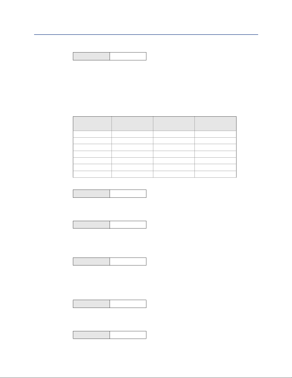
2.3.5 Mating pipe ID (Inside Diameter)
FastKeys 1, 3, 5
The Pipe ID (Inside Diameter) of the pipe adjacent to the flowmeter can cause entrance
effects that may alter flowmeter readings. You must specify the exact inside diameter of
the pipe to correct for these effects. Enter the appropriate value for this variable.
Pipe ID values for schedule 10, 40, and 80 piping are given in Table 2-1. If the piping in your
application is not one of these, you may need to contact the manufacturer for exact Pipe ID.
f
Table 2-1. Pipe IDs for Schedule 10, 40, and 80 Piping
Reference Manual
00809-0100-4860, Rev BD
Pipe Size
Inches (mm)
1 (25) 1.097 (27.86) 1.049 (26.64) 0.957 (24.31)
1? (40) 1.682 (42.72) 1.610 (40.89) 1.500 (38.10)
2 (50) 2.157 (54.79) 2.067 (52.50) 1.939 (49.25)
3 (80) 3.260 (82.80) 3.068 (77.93) 2.900 (73.66)
4 (100) 4.260 (108.2) 4.026 (102.3) 3.826 (97.18)
6 (150) 6.357 (161.5) 6.065 (154.1) 5.716 (145.2)
8 (200) 8.329 (211.6) 7.981 (202.7) 7.625 (193.7)
Schedule 10
Inches (mm)
2.3.6 Variable mapping
FastKeys 1, 3, 6
Allows the user to select which variables the Rosemount 8600D will output.
Primary Variable (PV)
FastKeys 1, 3, 6, 1
Selections for this Variable are Mass Flow, Volumetric Flow, Velocity Flow, and Process
Temperature. The Primary Variable is the variable mapped to the analog output.
Secondary Variable (SV)
Schedule 40
Inches (mm)
Schedule 80
Inches (mm)
16
FastKeys 1, 3, 6, 2
Selections for this Variable include all Variables that can be mapped to PV, and also Vortex
Frequency, Pulse Output Frequency, Totalizer Value, Calculated Process Density,
Electronics Temperature, and Cold Junction (CJ) Temperature.
Tertiary Variable (TV)
FastKeys 1, 3, 6, 3
Selections for this Variable are identical to those of the Secondary Variable.
Quaternary Variable (4V)
FastKeys 1, 3, 6, 4
Selections for this Variable are identical to those of the Secondary Variable.
Configuration
Page 25
Reference Manual
00809-0100-4860, Rev BD
2.3.7 PV units
FastKeys 1, 3, 7
Selections for this include all units available for the selection of PV. This will set the units for
the flow rate or process temperature.
2.3.8 Range values
FastKeys 1, 3, 8
Range Values enables you to maximize resolution of analog output. The meter is most
accurate when operated within the expected flow ranges for your application. Setting the
range to the limits of expected readings will maximize flowmeter performance.
The range of expected readings is defined by the Lower Range Value (LRV) and Upper
Range Value (URV). Set the LRV and URV within the limits of flowmeter operation as
defined by the line size and process material for your application. Values set outside that
range will not be accepted.
Primary Variable Upper Range Value (PV URV)
Configuration
October 2016
FastKeys 1, 3, 8, 1
This is the 20 mA set point for the meter.
Primary Variable Lower Range Value (PV LRV)
FastKeys 1, 3, 8, 2
This is the 4 mA set point for the meter, and is typically set to 0 when the PV is a Flow
Variable.
2.3.9 PV damping
FastKeys 1, 3, 9
Damping changes the response time of the flowmeter to smooth variations in output
readings caused by rapid changes in input. Damping is applied to the Analog Output,
Primary Variable, Percent of Range, and Vortex Frequency. This will not affect the Pulse
Output, Total, or other Digital Information.
The default damping value is 2.0 seconds. This can be reset to any value between 0.2 to 255
seconds when PV is a flow variable or 0.4 to 32 seconds when PV is Process Temperature.
Determine the appropriate damping setting based on the necessary response time, signal
stability, and other requirements of the loop dynamics in your system.
Note
If the vortex shedding frequency is slower than the damping value selected, no damping is
applied.
Configuration
17
Page 26

Configuration
October 2016
2.3.10 Auto adjust filter
FastKeys 1,3, Scroll to
Bottom
The Auto Adjust Filter is a function that can be used to optimize the range of the flowmeter
based on the density of the fluid. The electronics uses process density to calculate the
minimum measurable flow rate, while retaining at least a 4:1 signal to the trigger level
ratio. This function will also reset all of the filters to optimize the flowmeter performance
over the new range. If the configuration of the device has changed, this method should be
executed to ensure the signal processing parameters are set to their optimum settings. For
a stronger signal select a density value that is lower than the actual flowing density.
Reference Manual
00809-0100-4860, Rev BD
18
Configuration
Page 27
Reference Manual
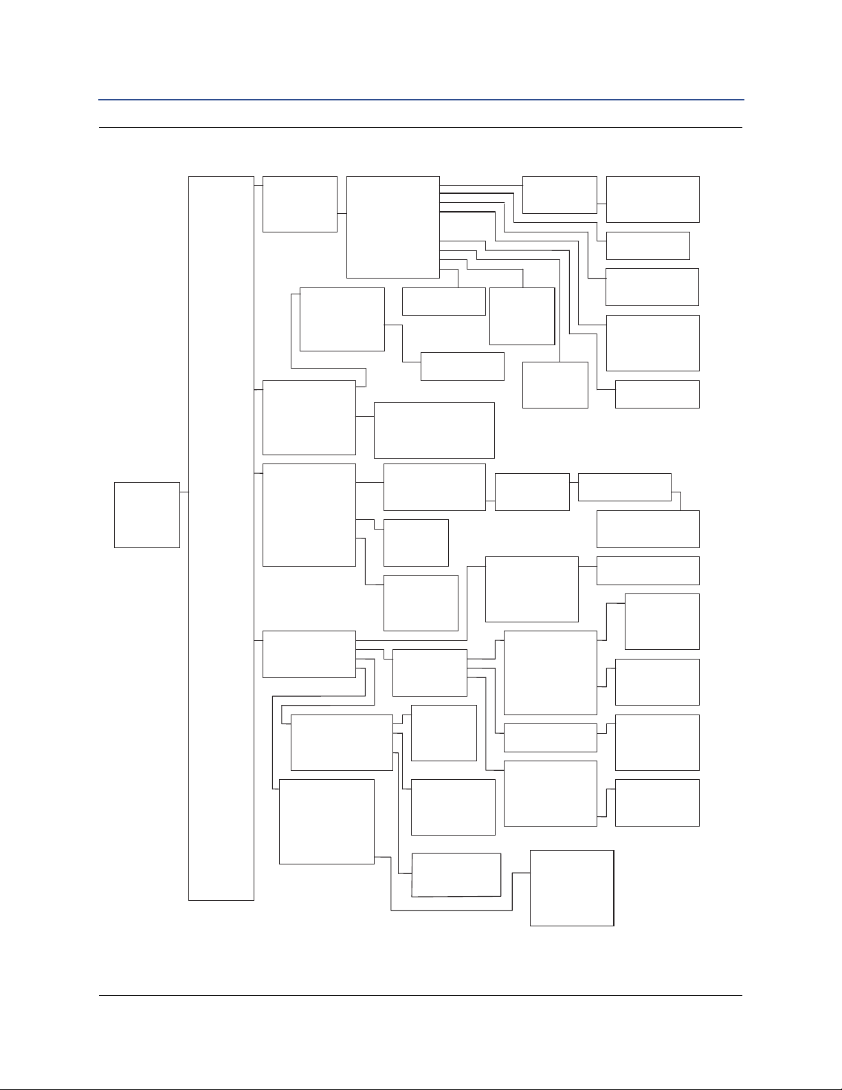
1. Device
Setup
2. PV
3. AO
4. LRV
5. URV
1. Process
Variables
2. Diagnostics
and Service
3. Basic Setup
4. Detailed
Setup
5. Review
1. PV
2. PV % Range
3. Analog Output
4. View Other
Variables
1. Volumetric Flow
2. Mass Flow
3. Velocity Flow
4. Totalizer
5. Pulse Frequency
6. Vortex Frequency
7. Electronics Temp
8. Calc Proc Density
9. Process Temp
- CJ Tem
p
erature
1. Volume Flow
2. Units
3. Special Units
1. Base Volume Unit
2. Base Time Unit
3. User Defined Unit
4. Conversion Number
1. Mass Flow
2. Mass Flow Unit
1. Total
2. Start
3. Stop
4. Reset
5. Totalizer Config
1. Electr Temp
2. Elec Temp Units
1. Test/Status
2. Loop Test
3. Pulse Output Test
4. Flow Simulation
5. D/A Trim
6. Scaled D/A Trim
7. Shed Fre
q
at URV
1. View Status
2. Config Status
3. Density Test Calc
4. Min/Max Temps
5. Self Test
6. Reset Xmt
r
1. PV
2. Shedding Frequency
3. Configure Flow Simulation
4. Enable Normal Flow
5. Mode
1. Tag
2. Process Config
3. Reference K Factor
4. Flange Type
5. Mating Pipe ID
6. Variable Mapping
7. PV Unit
8. Range Values
9. PV Damping
- Auto Ad
j
ust Filte
r
1. Transmitter Mode
2. Process Fluid
3. Fixed Process Temp
4. Density / Dens Ratio
1. Density Ratio
2. Fixed Process
Density
1. Density Ratio
2. Calc Density Ratio
1. PV is
2. SV is
3. TV is
4. QV is
1. URV
2. LRV
3. PV Min Span
4. USL
5. LSL
1. Operating Conditions
2. Base Conditions
3. Exit
1.Characterize Meter
2. Configure Outputs
3. Signal Processing
4. Device Information
1. K Factor
2. Mating Pipe ID
3. Flange Type
4. Wetted Material
5. Meter Body #
6. Installation Effects
1. Reference K Factor
2. Compensated K Factor
1.Anlg Output
2. Pulse Output
3.HART Output
4. Local Display
1. Range Values
2. Loop Test
3. Alarm Jumper
4. D/A Trim
5. Alarm Level Select
6. Alarm/Sat Levels
7. Scaled D/A Trim
8. Recall Factor
y
Trim
1. Vel. Flow
2. Vel. Flow Unit
3. Velocity Meas Base
1. High Alarm
2. High Saturation
3. Low Saturation
4. Low Alarm
1. Pulse Output
2. Pulse Output Test
1. Off
2. Direct (Shedding)
3. Scaled Volume
4. Scaled Velocity
5. Scaled Mass
1. Poll Address
2. # of Req Preams
3. Num Resp P reams
4. Burst Mode
5. Burst Option
6. Burst Xmtr Vars
1.Xmtr Var, Slot 1
2.Xmtr Var, Slot 2
3.Xmtr Var, Slot 3
4.Xmtr Var, Slot 4
1. Optimize Flow Range
2. Manual Filter Adjust
3. Filter Restore
4. Damping
5. LFC Response
1. Manufacturer
2. Tag
3. Descriptor
4. Message
5. Date
6. Write Protect
8. Revision Numbers
7. Transmitter Options
1. PV
2. LFC
3. Sig/Tr
4. Auto Adjust
Filter
1. PV
2. Sig/Tr
3. Low Flow Cutoff
4. Low Pass Filter
5. Trigger Level
1. Universal Rev
2. Transmitter Rev
3. Software Rev
4. Hardware Rev
5. Final Assembly #
6. Device ID
7. Board Serial #
1. Proc
Density
2. Density
Units
1. Proc Temp
2. Proc Temp
Units
3. T/C Failure
Mode
1. URV
2. LRV
3. PV Min Span
4. USL
5. LSL
1. CJ Temp
2. CJ Temp Units
1. Min Electr Temp
2. Max Electr Temp
1. PV Damping
2. Flow Damping
3. Temperature Damping
00809-0100-4860, Rev BD
Figure 2-1. Field Communicator Menu Tree for the Rosemount 8600D
Configuration
October 2016
Configuration
19
Page 28

Configuration
October 2016
Reference Manual
00809-0100-4860, Rev BD
Table 2-2. Field Communicator Fast Key Sequences for the Rosemount 8600D
Function Fast Keys Function Fast Keys
Alarm Jumper 1, 4, 2, 1, 3 Message 1, 4, 4, 4
Analog Output (Config) 1, 4, 2, 1 Meter Body Number 1, 4, 1, 5
Analog Output (View) 1, 1, 3 Minimum Span 1, 3, 8, 3
Auto Adjust Filter 1, 4, 3, 1, 4 Num Req Preams 1, 4, 2, 3, 2
Base Time Unit 1, 1, 4, 1, 3, 2 Poll Address 1, 4, 2, 3, 1
Base Volume Unit 1, 1, 4, 1, 3, 1 Process Fluid Type 1, 3, 2, 2
Burst Mode 1, 4, 2, 3, 4 Process Variables 1, 1
Burst Option 1, 4, 2, 3, 5 Pulse Output 1, 4, 2, 2, 1
Burst Variable 1 1, 4, 2, 3, 6, 1 Pulse Output Test 1, 4, 2, 2, 2
Burst Variable 2 1, 4, 2, 3, 6, 2 PV Damping 1, 3, 9
Burst Variable 3 1, 4, 2, 3, 6, 3 PV Mapping 1, 3, 6, 1
Burst Variable 4 1, 4, 2, 3, 6, 4 PV Percent Range 1, 1, 2
Burst Xmtr Variables 1, 4, 2, 3, 6 QV Mapping 1, 3, 6, 4
Conversion Number 1, 1, 4, 1, 3, 4 Range Values 1, 3, 8
D/A Trim 1, 2, 5 Review 1, 5
Date 1, 4, 4, 5 Revision Numbers 1, 4, 4, 7
Descriptor 1, 4, 4, 3 Scaled D/A Trim 1, 2, 6
Density Ratio 1, 3, 2, 4, 1, 1 Self Test 1, 2, 1, 5
Device ID 1, 4, 4, 7, 6 Signal to Trigger Ratio 1, 4, 3, 2, 2
Electronics Temp 1, 1, 4, 7, 1 STD/Nor Flow Units 1, 1, 4, 1, 2
Electronics Temp Units 1, 1, 4, 7, 2 Special Units 1, 1, 4, 1, 3
Filter Restore 1, 4, 3, 3 Status 1, 2, 1, 1
Final Assembly Number 1, 4, 4, 7, 5 SV Mapping 1, 3, 6, 2
Fixed Process Density 1, 3, 2, 4, 2 Tag 1, 3, 1
Fixed Process Temperature 1, 3, 2, 3 Total 1, 1, 4, 4, 1
Flange Type 1, 3, 4 Totalizer Control 1, 1, 4, 4
Flow Simulation 1, 2, 4 Transmitter Mode 1, 3, 2, 1
Installation Effects 1, 4, 1, 6 TV Mapping 1, 3, 6, 3
K-Factor (reference) 1, 3, 3 Trigger Level 1, 4, 3, 2, 5
Local Display 1, 4, 2, 4 URV 1, 3, 8, 1
Loop Test 1, 2, 2 User Defined Units 1, 1, 4, 1, 3, 3
Low Flow Cutoff 1, 4, 3, 2, 3 USL 1, 3, 8, 4
Low Pass Filter 1, 4, 3, 2, 4 Shedding Frequency 1, 1, 4, 6
LRV 1, 3, 8, 2 Variable Mapping 1, 3, 6
LSL 1, 3, 8, 5 Velocity Flow 1, 1, 4, 3
Manufacturer 1, 4, 4, 1 Velocity Flow Base 1, 1, 4, 3, 3
Mass Flow 1, 1, 4, 2, 1 Volumetric Flow 1, 1, 4, 1
Mass Flow Units 1, 1, 4, 2, 2 Wetted Material 1, 4, 1, 4
Mating Pipe ID (Inside Diameter) 1, 3, 5 Write Protect 1, 4, 4, 6
20
Configuration
Page 29

Reference Manual
00809-0100-4860, Rev BD
Section 3 Installation
Safety messages . . . . . . . . . . . . . . . . . . . . . . . . . . . . . . . . . . . . . . . . . . . . . . . . . . . . . . . . . . page 21
Commissioning . . . . . . . . . . . . . . . . . . . . . . . . . . . . . . . . . . . . . . . . . . . . . . . . . . . . . . . . . . . page 23
Hazardous locations . . . . . . . . . . . . . . . . . . . . . . . . . . . . . . . . . . . . . . . . . . . . . . . . . . . . . . page 27
Hardware configuration . . . . . . . . . . . . . . . . . . . . . . . . . . . . . . . . . . . . . . . . . . . . . . . . . . . page 27
Meter body installation tasks . . . . . . . . . . . . . . . . . . . . . . . . . . . . . . . . . . . . . . . . . . . . . . . page 29
Electronics considerations . . . . . . . . . . . . . . . . . . . . . . . . . . . . . . . . . . . . . . . . . . . . . . . . . page 32
Software configuration . . . . . . . . . . . . . . . . . . . . . . . . . . . . . . . . . . . . . . . . . . . . . . . . . . . . page 41
Transient protection . . . . . . . . . . . . . . . . . . . . . . . . . . . . . . . . . . . . . . . . . . . . . . . . . . . . . . page 44
This section provides installation instructions for the Rosemount 8600D Vortex Flowmeter.
Dimensional drawings for each Rosemount 8600D variation and mounting configuration
are included in the Appendix on page 100.
The options available for the Rosemount 8600D flowmeter are also described in this
section. The numbers in parentheses refer to the codes used to order each option.
Installation
October2016
3.1 Safety messages
Instructions and procedures in this section may require special precautions to ensure the
safety of the personnel performing the operations. Refer to the following safety messages
before performing any operation in this section.
Explosions could result in death or serious injury.
Do not remove the transmitter cover in explosive atmospheres when the circuit is
alive.
Before connecting a HART-based communicator in an explosive atmosphere, make
sure the instruments in the loop are installed in accordance with intrinsically safe or
non-incendive field wiring practices.
Verify the operating atmosphere of the transmitter is consistent with the appropriate
hazardous locations certifications.
Both transmitter covers must be fully engaged to meet explosion-proof
requirements.
Failure to follow these installation guidelines could result in death or serious injury.
Make sure only qualified personnel perform the installation.
Installation
21
Page 30
Installation
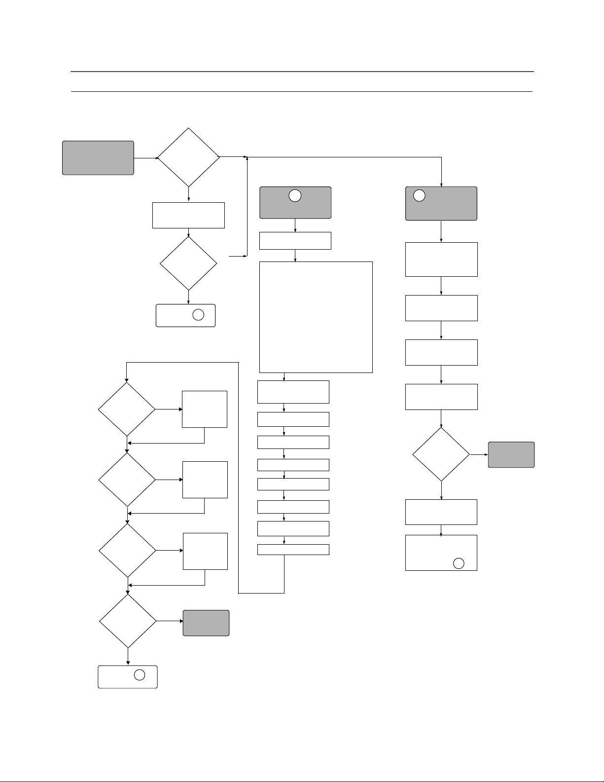
Is
Configuration
OK?
Mount
Flowmeter
Wire
Flowmeter
Power
Flowmeter
DONE
Mount
Conduit
START HERE
FIELD
INSTALL
CONFIGURE
Tag
Process Config
• Transmitter Mode
• Process Fluid
• Fixed Process Temp.
•Dens/Dens Ratio
-Density Ratio
(Std. or Normal
Volumetric Flow Units
Only)
-Fixed Process Density
(Mass Flow Units Only)
No
Bench
Commissioning?
Review
Configuration
Ye s
No
Ye s
Did you
Configure on
Bench?
No
Ye s
Configure if
Necessary
Go to
Review
Configuration
A
A
A
Go to
B
Go to
B
Reference
K-Factor
Mating Pipe ID
Variable Mapping
Flange Type
PV Unit
Range Values
PV Damping
Auto Adjust Filter
Using
LCD?
Yes
Configure
Local
Display
Using Pulse
Output
No
Using
Totalizer
Meter
Installed
Configure
Pulse
Output
Yes
No
Configure
Totalizer
Yes
No
Yes
No
DONE
October 2016
Figure 3-1. Installation Flowchart
Reference Manual
00809-0100-4860, Rev BD
22
Installation
Page 31

Reference Manual
00809-0100-4860, Rev BD
3.2 Commissioning
Commission the Rosemount 8600D before putting it into operation. This ensures proper
configuration and operation of the meter. It also enables you to check hardware settings,
test the flowmeter electronics, verify flowmeter configuration data, and check output
variables. Any problems can be corrected – or configuration settings changed – before
going out into the installation environment. To commission on the bench, connect the
Field Communicator or AMS
signal loop in accordance with the specifications for your communicator.
3.2.1 General considerations
Before you install a flowmeter in any application, you must consider flowmeter sizing (the
line size) and location. Choose the correct flowmeter size for an application to increase
rangeability and minimize pressure drop and cavitation. Proper location of the flowmeter
can ensure a clean and accurate signal. Follow the installation instructions carefully to
reduce start-up delays, ease maintenance, and ensure optimum performance.
™
Device Manager (or other communications device) to the
Installation
October2016
3.2.2 Flowmeter sizing
Correct meter sizing is important for flowmeter performance. The Rosemount 8600D is
capable of processing signals from flow applications within the limitations described in
Appendix A: Specifications and Reference Data. Full scale is continuously adjustable within
these ranges.
To determine the correct flowmeter size for an application, process conditions must be
within the stated requirements for Reynolds number and velocity. See Appendix A:
Specifications and Reference Data for sizing data.
Contact your local Rosemount Inc. sales representative to obtain a copy of Instrument
®
Toolkit
vortex sizing module will calculate valid flowmeter sizes based on user-supplied application
information.
which contains a sizing module for the Rosemount 8600D Vortex flowmeter. The
3.2.3 Flowmeter orientation
Design process piping so the meter body will remain full, with no entrapped air. Allow
enough straight pipe both upstream and downstream of the meter body to ensure a
nonskewed, symmetrical profile. Install valves downstream of the meter when possible.
Vertical installation
Vertical installation allows upward process liquid flow and is generally preferred. Upward
flow ensures that the meter body always remains full and that any solids in the fluid are
evenly distributed.
Installation
The vortex meter can be mounted in the vertical down position when measuring gas or
steam flows. This type of application should be strongly discouraged for liquid flows,
although it can be done with proper piping design.
23
Page 32

Installation
The meter body installed with the electronics to the side of the pipe.
(PREFERRED ORIENTATION)
The meter body installed with the
electronics below the pipe.
(ACCEPTABLE ORIENTATION)
October 2016
Reference Manual
00809-0100-4860, Rev BD
Note
To ensure the meter body remains full, avoid downward vertical liquid flows where back
pressure is inadequate.
Horizontal installation
For horizontal installation, the preferred orientation is to have the electronics installed to
the side of the pipe. In liquid applications, this ensures any entrapped air or solids do not
strike the shedding bar and disrupt the shedding frequency. In gas or steam applications,
this ensures that any entrained liquid (such as condensate) or solids do not strike the
shredder bar and disrupt the shedding frequency.
High-Temperature installations
Install the meter body so the electronics are positioned to the side of the pipe or below the
pipe as shown in Figure 3-2. Insulation may be required around the pipe to maintain an
electronics temperature below 185 °F (85 °C).
Figure 3-2. Examples of High-Temperature Installations
24
Steam installations
For steam applications, avoid installations such as the one shown in Figure 3-3. Such
installations may cause a water-hammer condition at start-up due to trapped condensate.
The high force from the water hammer can overstress the sensing mechanism and cause
permanent damage to the sensor.
Installation
Page 33

Reference Manual
00809-0100-4860, Rev BD
Figure 3-3. Avoid This Type of Installation for Steam Applications
Upstream/Downstream piping
The vortex meter may be installed with a minimum of ten diameters (D) of straight pipe
length upstream and five diameters (D) of straight pipe length downstream.
Installation
October2016
Rated accuracy is based on the number of pipe diameter from an upstream disturbance. No
K-factor correction is required if the meter is installed with 35 D upstream and 5 D
downstream. The value of the K-factor may shift up to 0.5% when the upstream straight
pipe length is between 10D and 35D. Please see Technical Data Sheet (00816-0100-3250)
on Installation Effects for optional K-factor corrections. This effect can be corrected for
using the Installation Effect Correction Factor (See page 52).
Pressure and temperature transmitter location
When using pressure and temperature transmitters in conjunction with the Rosemount
8600D for compensated mass flows, install the transmitter(s) downstream of the Vortex
Flowmeter. See Figure 3-4.
Installation
25
Page 34

Installation
A
D
B
C
October 2016
Reference Manual
00809-0100-4860, Rev BD
Figure 3-4. Pressure and Temperature Transmitter Location
Note
The MTA option can be purchased for an integral temperature measurement and mass flow
temperature compensation for saturated steam only.
A. Pressure transmitter
B. Four straight pipe diameters downstream
C. Temperature transmitter
D. Six straight pipe diameters downstream
3.2.4 Wetted material selection
Ensure the process fluid is compatible with the meter body wetted materials when
specifying the Rosemount 8600D. Corrosion will shorten the life of the meter body. Consult
recognized sources of corrosion data or contact your Rosemount Sales Representative for
more information.
Note
For accurate results perform a Positive Material Identification (PMI) test on a machined
surface.
3.2.5 Environmental considerations
Avoid excessive heat and vibration to ensure maximum flowmeter life. Typical problem
areas include high-vibration lines with integrally mounted electronics, warm-climate
installations in direct sunlight, and outdoor installations in cold climates.
26
Installation
Page 35

Reference Manual
00809-0100-4860, Rev BD
Although the signal conditioning functions reduce susceptibility to extraneous noise, some
environments are more suitable than others. Avoid placing the flowmeter or its wiring close to
devices that produce high intensity electromagnetic and electrostatic fields. Such devices
include electric welding equipment, large electric motors and transformers, and
communication transmitters.
3.3 Hazardous locations
The Rosemount 8600D has an explosion-proof housing and circuitry suitable for
intrinsically safe and non-incendive operation. Individual transmitters are clearly marked
with a tag indicating the certifications they carry.
3.4 Hardware configuration
The hardware jumpers on the Rosemount 8600D enable you to set the alarm and security.
(See Figure 3-5.) To access the jumpers, remove the electronics housing cover from the
electronics end of the Rosemount 8600D. If your Rosemount 8600D includes an LCD
option, the alarm and security jumpers are found on the face of the LCD indicator. (See
Figure 3-6 on page 29.)
Installation
October2016
Note
If you will be changing configuration variables frequently, it may be useful to leave the
security lockout jumper in the OFF position to avoid exposing the flowmeter electronics to
the plant environment.
Set these jumpers during the commissioning stage to avoid exposing the electronics to the
plant environment.
Figure 3-5. Alarm and Security Jumpers
Installation
27
Page 36

Installation
October 2016
00809-0100-4860, Rev BD
Alarm
As part of normal operations, the Rosemount 8600D continuously runs a self-diagnostic
routine. If the routine detects an internal failure in the electronics, flowmeter output is
driven to a low or high alarm level, depending on the position of the failure mode jumper.
The failure mode jumper is labeled ALARM and is set at the factory per the CDS
(Configuration Data Sheet); the default setting is HI.
Security
You can protect the configuration data with the security lockout jumper. With the security
lockout jumper ON, any configuration changes attempted on the electronics are
disallowed. You can still access and review any of the operating parameters and scroll
through the available changes, but no actual changes will be permitted. The security
lockout jumper is labeled SECURITY and is set at the factory per the CDS; the default setting
is OFF.
3.4.1 Failure mode vs. saturation output values
The failure mode alarm output levels differ from the output values that occur when the
operating flow is outside the range points. When the operating flow is outside the range
points, the analog output continues to track the operating flow until reaching the
saturation value listed below; the output does not exceed the listed saturation value
regardless of the operating flow. For example, with standard alarm and saturation levels
and flows outside the 4—20 mA range points, the output saturates at 3.9 mA or 20.8 mA.
When the transmitter diagnostics detect a failure, the analog output is set to a specific
alarm value that differs from the saturation value to allow for proper troubleshooting.
.
Table 3-1. Analog Output: Standard Alarm Values vs. Saturation Values
Reference Manual
Level 4—20 mA Saturation Value 4—20 mA Alarm Value
Low 3.9 mA < 3.75 mA
High 20.8 mA 21.75 mA
.
Table 3-2. Analog Output: NAMUR-Compliant Alarm Values vs. Saturation Values
Level 4—20 mA Saturation Value 4—20 mA Alarm Value
Low 3.8 mA < 3.6 mA
High 20.5 mA 22.6 mA
3.4.2 LCD indicator option
If your electronics are equipped with the LCD indicator (Option M5), the ALARM and
SECURITY jumpers are located on the face of the indicator as shown in Figure 3-6.
28
Installation
Page 37

Reference Manual
ALARM
LO
HI
OFF
ON
SECURITY
00809-0100-4860, Rev BD
Figure 3-6. LCD Indicator Alarm and Security Jumpers
Installation
October2016
3.5 Meter body installation tasks
The installation tasks include detailed mechanical and electrical installation procedures.
3.5.1 Handling
Handle all parts carefully to prevent damage. Whenever possible, transport the system to
the installation site in the original shipping containers. Keep the shipping plugs in the
conduit connections until you are ready to connect and seal them.
Note
Do not lift the flowmeter by the transmitter. Lift the meter by the meter body. If necessary,
Lifting supports can be tied around the meter body as shown in Figure 3-7.
Installation
29
Page 38

Installation
October 2016
Reference Manual
00809-0100-4860, Rev BD
Figure 3-7. Lifting Supports
3.5.2 Flow direction
Mount the meter body so the FORWARD end of the flow arrow, shown on the meter body,
points in the direction of the flow in the pipe.
3.5.3 Gaskets
The Rosemount 8600D requires flange gaskets supplied by the user, and sensor gaskets
supplied with the meter. Be sure to select gasket material that is compatible with the
process fluid and pressure ratings of the specific installation.
Note
Ensure that the inside diameter of the flange gasket is larger than the inside diameter of the
flowmeter and adjacent piping. If gasket material extends into the flow stream, it will
disturb the flow and cause inaccurate measurements.
30
Installation
Page 39

Reference Manual
B
Flow
A
00809-0100-4860, Rev BD
3.5.4 Flange bolts
Install the Rosemount 8600D Flowmeter between two conventional pipe flanges, as shown
in Figure 3-8 on page 31.
Figure 3-8. Flanged-Style Flowmeter Installation
Installation
October2016
A. Installation bolts and nuts (supplied by customer)
B. Gaskets (supplied by customer)
3.5.5 Flanged-style flowmeter mounting
Physical mounting of a flanged-style flowmeter is similar to installing a typical section of
pipe. Conventional tools, equipment, and accessories (such as bolts and gaskets) are
required. Tighten the nuts following the sequence shown in Figure 3-9.
Note
The required bolt load for sealing the gasket joint is affected by several factors, including
operating pressure and gasket material, width, and condition. A number of factors also affect
the actual bolt load resulting from a measured torque, including condition of bolt threads,
friction between the nut head and the flange, and parallelism of the flanges. Due to these
application-dependent factors, the required torque for each application may be different.
Follow the guidelines outlined in the ASME Pressure Vessel Code (Section VIII, Division 2) for
proper bolt tightening. Make sure the flowmeter is centered between flanges of the same
nominal size as the flowmeter.
Installation
31
Page 40

Installation
October 2016
Reference Manual
00809-0100-4860, Rev BD
Figure 3-9. Flange Bolt Torquing Sequence
3.5.6 Flowmeter grounding
Grounding is not required in typical vortex applications; however, a proper ground will
eliminate possible noise pickup by the electronics. Grounding straps may be used to ensure
that the meter is grounded to the process piping. If you are using the transient protection
option (T1), grounding straps are required to provide a proper low impedance ground.
Note
Properly ground flow meter body and transmitter per the local code.
To use grounding straps, secure one end of the grounding strap to the bolt extending from
the side of the meter body and attach the other end of each grounding strap to a suitable
ground.
3.6 Electronics considerations
Both integral and remote mounted electronics require input power at the electronics. For
remote mount installations, mount the electronics
against a flat surface or on a pipe that is up to two inches (50 mm) in diameter.
Remote mounting hardware includes an L bracket that is stainless steel and one stainless
steel u-bolt. See Appendix A: Specifications and Reference Data, “Dimensional drawings”
on page 100 for dimensional information.
3.6.1 High-Temperature installations
Install the meter body so the electronics are positioned to the side of or below the pipe as
shown in Figure 3-2 on page 24. Insulation may be required around the pipe to maintain an
ambient transmitter temperature below 185 °F (85 °C) or the more restrictive temperature
ratings marked on hazardous locations tags.
32
Installation
Page 41

Reference Manual
Conduit Line
Conduit Line
00809-0100-4860, Rev BD
3.6.2 Conduit connections
Installation
October2016
The electronics housing has two ports for 1/2–14 NPT or M2031.5 conduit connections.
Unless marked otherwise conduit entries in the housing are
made in a conventional manner in accordance with local or plant electrical codes. Be sure to
properly seal unused ports to prevent moisture or other contamination from entering the
terminal block compartment of the electronics housing. Additional conduit entry types are
available via adapters.
Note
In some applications it may be necessary to install conduit seals and arrange for conduits to
drain to prevent moisture from entering the wiring compartment.
3.6.3 High-Point installation
Prevent condensation in any conduit from flowing into the housing by mounting the
flowmeter at a high point in the conduit run. If the flowmeter is mounted at a low point in
the conduit run, the terminal compartment could fill with fluid.
If the conduit originates above the flowmeter, route conduit below the flowmeter before
entry. In some cases a drain seal may need to be installed.
Figure 3-10. Proper Conduit Installation with Rosemount 8600D
1
/2 NPT. These connections are
3.6.4 Cable gland
If you are using cable glands instead of conduit, follow the cable gland manufacturer’s
instructions for preparation and make the connections in a conventional manner in accordance
with local or plant electrical codes. Be sure to properly seal unused ports to prevent moisture or
Installation
other contamination from entering the terminal block compartment of the electronics
housing.
33
Page 42

Installation
October 2016
3.6.5 Grounding the transmitter case
The transmitter case should always be grounded in accordance with national and local
electrical codes. The most effective transmitter case grounding method is direct
connection to earth ground with minimal impedance. Methods for grounding the
transmitter case include:
Internal Ground Connection: The Internal Ground Connection screw is inside the
FIELD TERMINALS side of the electronics housing. This screw is identified by a
ground symbol ( ), and is standard on all Rosemount 8600D transmitters.
External Ground Assembly: This assembly is included with the optional transient
protection terminal block (Option Code T1). The External Ground Assembly can
also be ordered with the transmitter (Option Code V5) and is automatically
included with certain hazardous area approvals.
Note
Grounding the transmitter case using the threaded conduit connection may not provide a
sufficient ground. The transient protection terminal block (Option Code T1) does not
provide transient protection unless the transmitter case is properly grounded. See
“Transient Terminal Block” on page 45 for transient terminal block grounding. Use the
above guidelines to ground the transmitter case. Do not run the transient protection
ground wire with signal wiring as the ground wire may carry excessive current if a lightning
strike occurs.
Reference Manual
00809-0100-4860, Rev BD
3.6.6 Wiring procedure
The signal terminals are located in a compartment of the electronics housing separate from
the flowmeter electronics. Connections for a HART-based communicator and a current test
connection are above the signal terminals. Figure 3-11 illustrates the power supply load
limitations for the flowmeter.
Note
A power disconnect is required to remove power from the transmitter for maintenance,
removal, and replacement.
Power supply
Power Supply Specifications:
Typical installations use a 22 Vdc – 28 Vdc power supply. The dc power supply should
provide clean power with less than 2% ripple. Refer to Figure 3-11 as a quick reference.
Loop resistance specification:
If HART communication is required, a minimum resistance of 250Ω dc is required between
the power supply and the transmitter.
Note
See the Loop Load Calculation section to determine the maximum allowable loop
resistance as a function of power supply voltage.
34
Installation
Page 43

Reference Manual
8600
V
ps
R
loop
V
terminals
00809-0100-4860, Rev BD
Typical single loop wiring diagram:
Loop Load Calculation
Installation
October2016
R
loop(max)
= (Vps – 10.8) / 0.024
Where:
R
R
V
10.8 = minimum terminal voltage “V
0.024 = maximum transmitter current in Adc
loop(min)
loop(max)
ps
= 250 Ω. Required for HART communication.
= The maximum value the loop load resistor can be.
= Power Supply Voltage
terminals
Figure 3-11. Power Supply Load Limitations
” in Vdc.
Note
R
loop(max)
in the equation above refers to the total loop load resistance. Technically, the total
loop load resistance is the sum of the loop load resistor, signal wiring resistance, and if
applicable, any intrinsic safety barriers. In a typical installation, the loop load resistor will largely
determine the total loop resistance. In some installations, depending on signal wire gauge and
signal wire length, and/or any IS barriers, the additional resistance may need to be accounted
for.
Installation
35
Page 44

Installation
October 2016
Reference Manual
00809-0100-4860, Rev BD
To minimize noise pickup on the 4-20 mA signal and any digital communications signal:
Twisted pair wiring is recommended.
Shielded signal wire is preferred.
For high EMI/RFI environments, shielded signal wire is required.
To ensure proper operation, wiring should be:
24 AWG or larger.
Less than 5000 ft. (1500 m) in length.
Ohms per 1,000 ft (305 m) at 68 °F (20 °C)
Gage number A.W.G.
14 2.525
16 4.016
18 6.385
20 10.15
22 16.14
24 25.67
equivalent
Note
If an Emerson Smart Wireless THUM
™
Adapter is being used with the Rosemount 8600
flowmeter to exchange information via the WirelessHART protocol, an additional 2.5 Vdc is
dropped in the connected loop. This is because the THUM is wired in series with the
transmitter. Please use the following formula to calculate the maximum loop load resistor.
Loop Load Calculation: R
loop(max)
= (Vps – 10.8 – 2.5) / 0.024
Where:
R
V
10.8 = minimum terminal voltage “V
2.5 = Maximum voltage drop across the THUM wireless adapter.
0.024 = maximum transmitter current in Adc.
loop(max)
ps
= The maximum value the loop load resistor can be.
= Power Supply Voltage.
terminals
” in Vdc.
Analog output
The flowmeter provides a 4–20 mA dc isolated current output, linear
with the flow rate.
To make connections, remove the FIELD TERMINALS side cover of the electronics housing.
All power to the electronics is supplied over the 4–20 mA signal wiring. Connect the wires
as shown in Figure 3-14 on page 39.
36
Installation
Page 45

Reference Manual
50% Duty Cycle
00809-0100-4860, Rev BD
Pulse output
Note
Remember when using the pulse output, all power to the electronics is still supplied over
the 4–20 mA signal wiring.
The flowmeter provides an isolated transistor switch-closure frequency output signal
proportional to flow, as shown in Figure 3-12. The frequency limits are as follows:
Maximum Frequency = 10000 Hz
Minimum Frequency = 0.0000035 Hz (1 pulse/79 hours)
Duty Cycle = 50%
External Supply Voltage (V
Load Resistance (R
Max Switching Current = 75 mA >= V
Switch Closure: Transistor, open collector
Open contact < 50
Close contact < 20
): 5 to 30 Vdc
s
): 100 to 100 k
L
A leakage
Installation
October2016
S/RL
The output may drive an externally powered electromechanical or electronic totalizer, or
may serve as a direct input to a control element.
To connect the wires, remove the FIELD TERMINALS side cover of the electronics housing.
Connect the wires as shown in Figure 3-15 on page 39.
Figure 3-12. Example: Pulse Output Will Maintain a 50 Percent Duty Cycle for All
Frequencies
Installation
37
Page 46

Installation
A
B
C
October 2016
Reference Manual
00809-0100-4860, Rev BD
Note
When using pulse output, be sure to follow these precautions:
Shielded twisted pair is required when the pulse output and 4–20 mA output are
run in the same conduit or cable trays. Shielded wire will also reduce false
triggering caused by noise pickup. Wiring should be 24 AWG or larger and not
exceed 5,000 ft. (1500 m).
Do not connect the powered signal wiring to the test terminals. Power could
damage the test diode in the test connection.
Do not run signal wiring in conduit or open trays with power wiring or near heavy
electrical equipment. If needed, ground signal wiring at any one point on the signal
loop, such as the negative terminal of the power supply. The electronics housing is
grounded to the meter body.
If the flowmeter is protected by the optional transient protector, you must provide
a high-current ground connection from the electronics housing to earth ground.
Also, tighten the ground screw in the bottom center of the terminal block to
provide a good ground connection. See Figure 3-13.
Figure 3-13. The Transient Terminal Block
A. Housing ground screw
B. Captive screws
C. Transient terminal block ground tab
Plug and seal all unused conduit connections on the electronics housing to avoid
moisture accumulation in the terminal side
of the housing.
If the connections are not sealed, mount the flowmeter with the conduit entry
positioned downward for drainage. Install wiring with a drip loop, making sure the
bottom of the drip loop is lower than the conduit connections or the electronics
housing.
38
Installation
Page 47

Reference Manual
+
-
R
L
250
A
+
A
+
–
-
B
R
L
250
00809-0100-4860, Rev BD
Figure 3-14. 4-20 mA Wiring
A. Test ammeter
Installation
October2016
Figure 3-15. 4–20 mA and Pulse Wiring with Electronic Totalizer/ Counter
A. Test ammeter
B. Pulse counter
3.6.7 Remote electronics
If you order one of the remote electronics options (options R10, R20, R30, R33, R50, or
RXX), the flowmeter assembly will be shipped in two parts:
1. The meter body with an adapter installed in the bracket and an interconnecting
coaxial cable attached to it.
Installation
2. The electronics housing installed on a mounting bracket.
39
Page 48

Installation
K
M
N
J
P
L
O
H
G
F
E
C
A
D
B
I
October 2016
Mounting
Mount the meter body in the process flow line as described earlier in this section. Mount
the bracket and electronics housing in the desired location. The housing can be
repositioned on the bracket to facilitate field wiring and conduit routing.
Cable connections
Refer to Figure 3-16 and the following instructions to connect the loose end of the coaxial
cable to the electronics housing. (See “Remote electronics procedure” on page 83 if connecting/disconnecting the meter adapter to the meter body.)
Figure 3-16. Remote Electronics Installation
Reference Manual
00809-0100-4860, Rev BD
40
Note
Consult factory for SST installation.
A. Meter body I. 1/2 in. NPT Conduit adapter or cable gland (supplied by customer)
B. Bracket J. Electronics housing
C. Sensor cable nut K. Ground connection
D. Nut L. Housing base screw
E. Washer M. Housing adapter
F. Union N. Housing adapter screws
G. Meter adapter O.
H. Coaxial cable P. Coaxial cable nut
1
/2 in. NPT conduit adapter or cable gland (supplied by customer)
1. If you plan to run the coaxial cable in conduit, carefully cut the conduit to the desired length to provide for proper assembly at the housing. A junction box may be placed in the conduit run to provide a space for extra coaxial cable length.
Installation
Page 49

Reference Manual
00809-0100-4860, Rev BD
2. Slide the conduit adapter or cable gland over the loose end of the coaxial cable and
3. If using conduit, route the coaxial cable through the conduit.
4. Place a conduit adapter or cable gland over the end of the coaxial cable.
5. Remove the housing adapter from the electronics housing.
6. Slide the housing adapter over the coaxial cable.
7. Remove one of the four housing base screws.
8. Attach the coaxial cable ground wire to the housing via the housing base ground screw.
9. Attach and securely tighten the coaxial cable nut to the connection on the electronics
10. Align the housing adapter with the housing and attach with two screws.
11. Tighten the conduit adapter or cable gland to the housing adapter.
Installation
October2016
fasten it to the adapter on the meter body bracket.
housing.
To prevent moisture from entering the coaxial cable connections, install the
interconnecting coaxial cable in a single dedicated conduit run or use sealed cable glands
at both ends of the cable.
3.6.8 Calibration
Rosemount 8600D Flowmeters are wet-calibrated at the factory and need no further calibration
during installation. The calibration factor (K-factor) is indicated on each meter body and is
entered into the electronics. Verification can be accomplished with a Field Communicator
or AMS.
3.7 Software configuration
To complete the installation of the Rosemount 8600D Vortex Flowmeter, configure the
software to meet the requirements of your application. If the flowmeter was pre-configured at
the factory, it may be ready to install. If not, refer to Section 2: Configuration.
LCD indicator
The LCD indicator (option M5) provides local indication of the output and abbreviated
diagnostic messages governing operation of the flowmeter. The indicator is located on the
electronics side of the flowmeter electronics. An extended cover is required to accommodate
the indicator. Figure 3-17 shows the flowmeter fitted with the LCD indicator and extended
cover.
Installation
41
Page 50

Installation
A
October 2016
Reference Manual
00809-0100-4860, Rev BD
Figure 3-17. Rosemount 8600D with Optional Indicator
A. Electronics board
The indicator features an eight-character (and five alphanumeric) liquid crystal display that
gives a direct reading of the digital signal from the microprocessor. During normal
operation, the display can be configured to alternate between the following readings:
Primary variable in engineering units
Percent of range
Totalized flow
4–20 mA electrical current output
Shedding Frequency
Electronics Temperature
Pulse Output Frequency
Process Temperature (MTA Option Only)
Mass Flow
Volume Flow
Velocity Flow
Calculated Process Density (MTA Option Only)
42
Installation
Page 51

Reference Manual
00809-0100-4860, Rev BD
Figure 3-18 shows the indicator display with all segments lit.
Figure 3-18. Optional Liquid Crystal Display
Installation
October2016
A HART-based communicator can be used to change the engineering units of the
parameters displayed on the indicator. (SeeSection 4: Operation for more information).
3.7.1 Installing the indicator
For flowmeters ordered with the LCD indicator, the indicator is shipped installed. When
purchased separately from the Rosemount 8600D, you must install the indicator using a
small instrument screwdriver and the indicator kit (part number 8600-5640). The indicator
kit includes:
One LCD indicator assembly
One extended cover with o-ring installed
One connector
Two mounting screws
Two jumpers
Referring to Figure 3-17, use the following steps to install the
LCD indicator:
1. If the flowmeter is installed in a loop, secure the loop and disconnect the power.
2. Remove the flowmeter cover on the electronics side.
Note
The circuit board is electrostatically sensitive. Be sure to observe handling precautions for
static-sensitive components.
Installation
3. Insert the mounting screws into the LCD indicator.
4. Remove the two jumpers on the circuit board that coincide with the Alarm and the Security settings.
43
Page 52

Installation
October 2016
Reference Manual
00809-0100-4860, Rev BD
5. Insert the connector into the Alarm / Security junction.
6. Gently slide the LCD indicator onto the connector and tighten the screws into place.
7. Insert jumpers into ALARM and SECURITY positions on the face of the LCD indicator.
8. Attach the extended cover and tighten at least one-third turn past o-ring contact.
Note
The indicator may be installed in 90-degree increments for easy viewing. Mounting screws
may need to be installed in the alternative holes based on LCD orientation. One of the four
connectors on the back of the indicator assembly must be positioned to fit into the ten-pin
connector on the electronic board stack.
Note the following LCD temperature limits:
Operating: –4 to 185 °F (–20 to 85 °C)
Storage: –50 to 185 °F (–46 to 85 °C)
3.8 Transient protection
The optional transient terminal block prevents damage to the flowmeter from transients
induced by lightning, welding, heavy electrical equipment, or switch gears. The transient
protection electronics are located in the terminal block.
The transient terminal block meets the following specifications:
IEEE C62.41 - 2002 Category B.
3 kA crest (8 X 20
6 kV crest (1.2 X 50
6 kV/0.5 kA (0.5
Note
The ground screw inside the terminal housing must be tightened for the proper operation
of the transient protection. Also, a high-current ground connection to earth is required.
3.8.1 Installing the Transient Protector
For flowmeters ordered with the transient protector option (T1), the protector is shipped
installed. When purchased separately from the Rosemount 8600D, you must install the
protector on a Rosemount 8600D flowmeter using a small instrument screwdriver, a pliers,
and the transient protection kit.
s)
s)
s, 100 kHz, ring wave)
44
The transient protection kit includes the following:
One transient protection terminal block assembly
Three captive screws
Installation
Page 53

Reference Manual
C
B
A
00809-0100-4860, Rev BD
Use the following steps to install the transient protector:
1. If the flowmeter is installed in a loop, secure the loop and disconnect power.
2. Remove the field terminal side flowmeter cover.
3. Remove the captive screws.
4. Remove the housing ground screw.
5. Use pliers to pull the terminal block out of the housing.
6. Inspect the connector pins for straightness.
7. Place the new terminal block in position and carefully press it into place. The
8. Tighten the captive screws.
9. Install and tighten the ground screw.
Installation
October2016
terminal block may have to be moved back and forth to get the connector pins
started into the sockets.
10. Replace the cover.
Figure 3-19. Transient Terminal Block
A. Housing Ground Screw
B. Captive Screws
C. Transient Terminal Block Ground Tab
Installation
45
Page 54

Installation
October 2016
Reference Manual
00809-0100-4860, Rev BD
46
Installation
Page 55

Reference Manual
00809-0100-4860, Rev BD
Section 4 Operation
Diagnostics/service . . . . . . . . . . . . . . . . . . . . . . . . . . . . . . . . . . . . . . . . . . . . . . . . . . . . . page 47
Advanced functionality . . . . . . . . . . . . . . . . . . . . . . . . . . . . . . . . . . . . . . . . . . . . . . . . . . page 51
Detailed set-up . . . . . . . . . . . . . . . . . . . . . . . . . . . . . . . . . . . . . . . . . . . . . . . . . . . . . . . . . page 51
This section contains information for advanced configuration parameters and diagnostics.
The software configuration settings for the Rosemount 8600D can be accessed through a
HART-based communicator or through a control system. The software functions for the Field
Communicator are described in detail in this section of the manual. It provides an overview
and summary of communicator functions. For more complete instructions, see the
communicator manual.
Before operating the Rosemount 8600D in an actual installation, you should review all of
the factory set configuration data to ensure that they reflect the current application.
Operation
October 2016
4.1 Diagnostics/service
FastKeys
Use the following functions to verify that the flowmeter is functioning properly, or when
you suspect component failure or a problem with loop performance, or when instructed to
do so as part of a troubleshooting procedure. Initiate each test with the Field
Communicator or other HART-based communications device.
4.1.1 Test/status
FastKeys. 1, 2, 1
Under Test/Status choose from View Status or Self Test.
View status
FastKeys. 1, 2, 1, 1
Allows you to view any error messages that may have occurred.
Configuration status
FastKeys 1, 2, 1, 2
Allows you to check the validity of the transmitter configuration.
1, 2
Operation
Density test calc
FastKeys 1, 2, 1, 3
Allows for the test of the density calculation for saturated steam. The vortex meter will
calculate the associated steam density at a user entered temperature value. Process Fluid
must be set to Tcomp Sat Steam in order to run this test.
47
Page 56

Operation
October 2016
Reference Manual
00809-0100-4860, Rev BD
Min/Max electronics temperatures
FastKeys 1, 2, 1, 4
Allows the user to view the minimum and maximum temperatures that the electronics
have been exposed to.
Min electronics temp
FastKeys 1, 2, 1, 4, 1
Displays the lowest temperature that the electronics have been exposed to.
Max electronics temp
FastKeys 1, 2, 1, 4, 2
Displays the highest temperature that the electronics have been exposed to.
Self test
FastKeys 1, 2, 1, 5
Although the Rosemount 8600D performs continuous self-diagnostics, you can initiate an
immediate diagnostic to check for possible electronics failure.
Self Test checks proper communications with the transmitter and provides diagnostic
capabilities for transmitter problems. Follow on-screen instructions if problems are
detected, or check the appropriate appendix for error messages relating to your
transmitter.
Reset transmitter
FastKeys 1, 2, 1, 6
Restarts the transmitter - same as cycling power.
4.1.2 Loop test
FastKeys 1, 2, 2
Verifies the output of the flowmeter, the integrity of the loop, and the operation of any
recorders or similar devices. Conduct the loop test after the flowmeter is installed in the
field.
If the meter is located in a loop with a control system, the loop will have to be set to manual
control before the loop test is performed.
Loop Test allows the device to be set to any output between the Low Alarm and High Alarm.
4.1.3 Pulse output test
FastKeys 1, 2, 3
A fixed frequency mode test that checks the integrity of the pulse loop. It tests that all
connections are good and that the pulse output is running on the loop.
48
Operation
Page 57

Reference Manual
00809-0100-4860, Rev BD
4.1.4 Flow simulation
FastKeys 1, 2, 4
Enables you to check the electronics functionality. This can be verified with either the Flow
Simulation Internal or Flow Simulation External method. PV must be Volume Flow, Velocity
Flow, or Mass Flow before Flow Simulation can be used.
PV
FastKeys 1, 2, 4, 1
Shows the flow value in current engineering units for the flow simulation.
Shedding frequency
FastKeys 1, 2, 4, 2
Shows the shedding frequency for the flow simulation.
Configure flow simulation
Operation
October 2016
FastKeys 1, 2, 4, 3
Allows you to configure your flow simulation (internal or external).
Simulate flow internal
FastKeys 1, 2, 4, 3, 1
When licensed, the simulate flow internal function will automatically electronically
disconnect the sensor and enable you to configure the internal flow simulation (fixed or
varying).
Fixed flow
FastKeys 1, 2, 4, 3, 1, 1
The fixed flow simulation signal can be entered in either a percent of range or flow rate in
current engineering units. This simulation locks the Vortex in to the specific flow rate
entered.
Varying flow
FastKeys 1, 2, 4, 3, 1, 2
The minimum and maximum flowrate can be entered in either percent of range or as a flow
rate in current engineering units. The ramp time can be entered in seconds from a
minimum of 0.6 seconds to a maximum of 34951 seconds. This simulation causes the
Vortex meter to continuously ramp from the minimum entered rate to the maximum
entered rate and back over the ramp time.
Operation
Simulate flow external
FastKeys 1, 2, 4, 3, 2
Allows you to disconnect the sensor electronically so an external frequency source can be
used to test and verify the electronics.
49
Page 58

Operation
October 2016
Enable normal flow
FastKeys 1, 2, 4, 4
Allows you to exit the flow simulation mode (internal or external) and return to normal
operation mode. Enabled Normal Flow must be activated after any simulation is run. Failure
to enable normal flow will leave the Vortex in simulation mode.
Mode
FastKeys 1, 2, 4, 5
Allows you to view which flow simulation mode you are in:
Internal (flow simulation – internal)
Snsr Offln (flow simulation – external)
Norm Flow (normal flow operation)
4.1.5 D/A trim(Digital-to-Analog Trim)
FastKeys 1, 2, 5
Reference Manual
00809-0100-4860, Rev BD
Enables you to check and trim the analog output in a single function. If the analog output is
trimmed, it will be scaled proportionally through the range of the output.
To trim the digital-to-analog output, initiate the D/A Trim function and connect an
ammeter to the loop to measure the actual analog output of the meter. Follow the
on-screen functions to complete the task.
4.1.6 Scaled D/A trim
FastKeys 1, 2, 6
Enables you to calibrate the flowmeter analog output using a different scale than the
standard 4-20 mA output scale. Non-scaled D/A Trimming (described above), is typically
performed using an ammeter where calibration values are entered in units of milliamperes.
Both non-scaled D/A trimming and scaled D/A trimming allow you to trim the 4-20mA
output to approximately ±5% of the nominal 4mA end point and ±3% of the nominal 20mA
end point. Scaled D/A Trimming allows you to trim the flowmeter using a scale that may be
more convenient based upon your method of measurement.
For example, it may be more convenient for you to make current measurements by direct
voltage readings across the loop resistor. If your loop resistor is 500 Ohms, and you want to
calibrate the meter using voltage measurements made across this resistor, you could
rescale (select CHANGE on the 375) your trim points from 4-20 mA to 4-20 mA x 500 ohm
or 2-10 Vdc. Once your scaled trim points have been entered as 2 and 10, you can now
calibrate your flowmeter by entering voltage measurements directly from the voltmeter.
50
Operation
Page 59

Reference Manual
00809-0100-4860, Rev BD
4.1.7 Shed freq at URV
FastKeys 1, 2, 7
Gives the shedding frequency corresponding to your URV (URV = Upper Range Value). If
the PV is Process Temperature, the Shedding Frequency at URV represents the shedding
frequency of the Volumetric Flow URV. This can be set by assigning Volumetric Flow to PV
and setting range values.
4.2 Advanced functionality
The Rosemount 8600D enables you to configure the flowmeter for a wider range of
applications and special situations. These functions are grouped as follows under Detailed
Set-Up:
4.3 Detailed set-up
FastKeys 1, 4
Characterize Meter
Operation
October 2016
Configure Outputs
Signal Processing
Device Information
4.3.1 Characterize meter
FastKeys 1, 4, 1
The meter body variables provide configuration data that are unique to your Rosemount
8600D. The settings of these variables can affect the compensated K-factor on which the
primary variable is based. This data is provided during factory configuration and should not
be changed unless the physical make-up of your Rosemount 8600D is changed.
K-factor
FastKeys 1, 4, 1, 1
The Field Communicator provides information on Reference and Compensated K-factor
values.
The Reference K-factor is factory set according to the actual K-factor for your application. It
should only be changed if you replace parts of the flowmeter. Contact your Rosemount
representative for details.
The Compensated K-factor is based on the reference K-factor as compensated for the given
process temperature, wetted materials, body number, and pipe ID. Compensated K-factor
is an informational variable that is calculated by the electronics of your flowmeter.
Operation
51
Page 60

Operation
October 2016
Reference Manual
00809-0100-4860, Rev BD
Mating pipe I.D.
FastKeys 1, 4, 1, 2
The inside diameter of the pipe adjacent to the flow meter can cause entrance effects that
may alter flowmeter readings. The exact inside diameter of the pipe must be specified to
correct for these effects. Enter the appropriate value for this variable.
Mating Pipe ID values for schedule 10, 40, 80, and 160 piping are given in Table 2-1 on
page 16. If the piping in your application is not one of these, you may need to contact the
manufacturer for exact Pipe ID.
Flange type
FastKeys 1, 4, 1, 3
Enables you to specify the type of flange on the flowmeter for later reference. This variable
is preset at the factory but can be changed if necessary.
ANSI 150
ANSI 300
PN16
PN40
Spcl
Wetted material
FastKeys 1, 4, 1, 4
A factory-set configuration variable that reflects the construction of your flowmeter.
316 SST
Spcl
Meter body number
FastKeys 1, 4, 1, 5
A factory-set configuration variable that stores the body number of your particular
flowmeter and the type of construction. The meter body number is found to the right of the
body number on the meter body tag, which is attached to the bracket of the meter body.
The format of this variable is a number followed by an alpha character. The number
designates the body number.
Installation effect
FastKeys 1, 4, 1, 6
Enables you to compensate the flowmeter for installation effects caused by less than ideal
straight run piping. See reference graphs located in Technical Data Sheet
00816-0100-3250 for the percent of K-factor shift based on entrance effects of upstream
disturbances. This value is entered as a percentage of the range of -1.5% to +1.5%.
52
Operation
Page 61

Reference Manual
00809-0100-4860, Rev BD
4.3.2 Configure outputs
FastKeys 1, 4, 2
The Rosemount 8600D is digitally adjusted at the factory using precision equipment to
ensure accuracy. You should be able to install and operate the flowmeter without a D/A
Trim.
Analog output
FastKeys 1, 4, 2, 1
For maximum accuracy, calibrate the analog output and, if necessary, trim for your system
loop. The D/A Trim procedure alters the conversion of the digital signal into an analog 4–20
mA output.
Range values
FastKeys 1, 4, 2, 1, 1
Enables you to maximize resolution of analog output. The meter is most accurate when
operated within the expected flow ranges for your application. Setting the range to the
limits of expected readings will maximize flowmeter performance.
Operation
October 2016
The range of expected readings is defined by the Lower Range Value (LRV) and Upper
Range Value (URV). Set the LRV and URV within the limits of flowmeter operation as
defined by the line size and process material for your application. Values set outside that
range will not be accepted.
Loop test
FastKeys 1, 4, 2, 1, 2
Verifies the output of the flowmeter, the integrity of the loop, and the operation of any
recorders or similar devices. Conduct the loop test after the flowmeter is installed in the
field. If the meter is located in a loop with a control system, the loop will have to be set to
manual control before the loop test is performed.
Loop Test allows the device to be set to any output between the Low Alarm and High Alarm.
Alarm jumper
FastKeys 1, 4, 2, 1, 3
Allows you verify the alarm jumper setting.
D/A trim (Digital-to-Analog trim)
FastKeys 1, 4, 2, 1, 4
Enables you to check and trim the analog output in a single function. If the analog output is
trimmed, it will be scaled proportionally through the range of the output. To trim the digital-to-analog output, initiate the D/A Trim function and connect an ammeter to the loop to
measure the actual analog output of the meter. Follow the on-screen functions to
complete the task.
Operation
53
Page 62

Operation
October 2016
Reference Manual
00809-0100-4860, Rev BD
Alarm level select
FastKeys 1, 4, 2, 1, 5
Allows you to select the alarm level of the transmitter. Either Rosemount standard or
NAMUR compliant.
Alarm/sat levels
FastKeys 1, 4, 2, 1, 6
Displays alarm and saturation mA output levels.
Note
Alarm and saturation levels can be found in the specifications section.
Scaled D/A trim
FastKeys 1, 4, 2, 1, 7
enables you to calibrate the flowmeter analog output using a different scale than the
standard 4-20 mA output scale. Non-scaled D/A Trimming (described above), is typically
performed using an ammeter where calibration values are entered in units of milliamperes.
Both non-scaled D/A trimming and scaled D/A trimming allow you to trim the 4-20mA
output to approximately ±5% of the nominal 4mA end point and ±3% of the nominal 20mA
end point. Scaled D/A Trimming allows you to trim the flowmeter using a scale that may be
more convenient based upon your method of measurement.
For example, it may be more convenient for you to make current measurements by direct
voltage readings across the loop resistor. If your loop resistor is 500 Ohms, and you want to
calibrate the meter using voltage measurements made across this resistor, you could
rescale your trim points from 4-20mA to 4-20mA x 500 ohm or 2-10 Vdc. Once your scaled
trim points have been entered as 2 and 10, you can now calibrate your flowmeter by
entering voltage measurements directly from the voltmeter.
Recall factory Trim
FastKeys 1, 4, 2, 1, 8
Enables you to return to the original factory trim values.
Pulse output
FastKeys 1, 4, 2, 2
Enables you to configure the Pulse Output.
Note
The Field Communicator will allow configuration of the pulse features even if the pulse
option (Option P) was not ordered.
54
Operation
Page 63

Reference Manual
00809-0100-4860, Rev BD
Pulse output
FastKeys 1, 4, 2, 2, 1
The Rosemount 8600D comes with an optional pulse output option (P). This enables the
flowmeter to output the pulse rate to an external control system, totalizer, or other device.
If the flowmeter was ordered with the pulse mode option, it may be configured for either
pulse scaling (based on rate or unit) or shedding frequency output. There are four methods
for configuring the pulse output:
Off
Direct (Shedding Frequency)
Scaled Volume
Scaled Velocity
Scaled Mass
Operation
October 2016
Direct (shedding frequency
)
FastKeys 1, 4, 2, 2, 1, 2
This mode provides the vortex shedding frequency as output. In this mode, the software
does not compensate the K-factor for effects such as thermal expansion or differing mating
pipe inside diameters. Scaled pulse mode must be used to compensate the K-factor for
thermal expansion and mating pipe effects.
Scaled volume
FastKeys 1, 4, 2, 2, 1, 3
Allows you to configure the pulse output based on a volumetric flow rate. For example, set
100 gallons per minute = 10,000 Hz. (The user enterable parameters are flow rate and
frequency.)
Pulse scaling rate
FastKeys 1, 4, 2, 2, 1, 3, 1
Allows the user to set a certain volume flow rate to a desired Frequency.
For example:
1. Enter a flow rate of 100 gallons per minute.
Operation
2. Enter a frequency of 10,000 Hz.
Pulse scaling unit
FastKeys 1, 4, 2, 2, 1, 3, 2
Allows the user to set one pulse equal to a desired volume.
For example:
1 pulse = 100 gal. Enter 100 for the Flow Rate.
55
Page 64

Operation
October 2016
Reference Manual
00809-0100-4860, Rev BD
Scaled velocity
FastKeys 1, 4, 2, 2, 1, 4
Allows you to configure the pulse output based on a velocity Flow Rate.
Pulse scaling rate
FastKeys 1, 4, 2, 2, 1, 4, 1
Allows the user to set a certain velocity flow rate to a desired frequency.
For example:
10 ft/sec = 10,000HZ
1. Enter a Flow rate of 10 ft/sec.
2. Enter a Frequency of 10,000HZ.
Pulse scaling unit
FastKeys 1, 4, 2, 2, 1, 4, 2
Allows the user to set one pulse equal to a desired distance.
For example:
1 pulse = 10 ft. Enter 10 for the distance.
Scaled mass
FastKeys 1, 4, 2, 2, 1, 5
Allows you to configure the pulse output based on a mass Flow Rate. If Process Fluid =
Tcomp Sat Steam, this is a temperature compensated mass flow.
Pulse scaling rate
FastKeys 1, 4, 2, 2, 1, 5, 1
Allows the user to set a certain mass Flow Rate to a desired Frequency.
For example:
1000 lbs/hr = 1000HZ
1. Enter a Flow rate of 1000 lbs/hr.
2. Enter a Frequency of 1000HZ.
56
Operation
Page 65

Reference Manual
Power
Supply
RS-232-C
Bell 202
Modem
00809-0100-4860, Rev BD
Pulse scaling unit
FastKeys 1, 4, 2, 2, 1, 5, 2
Allows the user to set one pulse equal to a desired mass.
For example:
1 pulse = 1000lbs.
Enter 1000 for the mass.
Pulse output test
FastKeys 1, 4, 2, 2, 2
A fixed frequency mode test that checks the integrity of the pulse loop. It tests that all
connections are good and that pulse output is running on the loop.
HART output
FastKeys 1, 4, 2, 3
Refers to the connection of several flowmeters to a single communications transmission
line. Communication occurs digitally between a HART-based communicator or control
system and the flowmeters. Multidrop mode automatically deactivates the analog output
of the flowmeters. Using the HART communications protocol, up to 15 transmitters can be
connected on a single twisted pair of wires or over leased phone lines.
Operation
October 2016
The use of a multidrop installation requires consideration of the update rate necessary from
each transmitter, the combination of transmitter models, and the length of the
transmission line. Multidrop installations are not recommended where intrinsic safety is a
requirement. Communication with the transmitters can be accomplished with
commercially available Bell 202 modems and a host implementing the HART protocol. Each
transmitter is identified by a unique address (1-15) and responds to the commands defined
in the HART protocol.
Figure 4-1 shows a typical multi-drop network. This figure is not intended as an installation
diagram. Contact Rosemount product support with specific requirements for multi-drop
applications.
Figure 4-1. Typical Multidrop Network
Operation
57
Page 66

Operation
October 2016
Reference Manual
00809-0100-4860, Rev BD
Note
The Rosemount 8600D is set to poll address zero at the factory, allowing it to operate in the
standard point-to-point manner with a 4–20 mA output signal. To activate multidrop
communication, the transmitter poll address must be changed to a number between 1 and
15. This change deactivates the 4–20 mA analog output, setting it to 4 mA, and disables
the failure mode alarm signal.
Poll address
FastKeys 1, 4, 2, 3, 1
Enables you to set the poll address for a multi-dropped meter. The poll address is used to
identify each meter on the multi-drop line. Follow the on-screen instructions to set the
address at a number from 1 to 15. To set or change the flowmeter address, establish
communication with the selected Rosemount 8600D in the loop.
Auto poll
FastKeys OFF LINE FCN
When a HART-based communicator is powered up and auto polling is on, the
communicator automatically polls the flowmeter addresses to which it is connected. If the
address is 0, the HART-based communicator enters its normal online mode. If it detects an
address other than 0, the communicator finds each device in the loop and lists them by poll
address and tag. Scroll through the list and select the meter with which you need to
communicate.
If Auto Poll is off, the flowmeter must have the poll address set to 0 or the flowmeter will
not be found. If a single connected device has an address other than zero and auto polling is
off, the device will not be found either.
Number of required preams
FastKeys 1, 4, 2, 3, 2
The number of preambles required by the 8600D for HART communications.
Number of response preams
FastKeys 1, 4, 2, 3, 3
The number of preambles sent by the transmitter in response to any host request.
Burst mode
FastKeys 1, 4, 2, 3, 4
Burst mode configuration
The Rosemount 8600D includes a burst mode function that broadcasts the primary
variable or all dynamic variables approximately three to four times a second. The burst
mode is a specialized function used in very specific applications. The burst mode function
enables you to select the variables to broadcast while in the burst mode and to select the
burst mode option.
58
Operation
Page 67

Reference Manual
00809-0100-4860, Rev BD
The Burst Mode variable enables you to set the Burst Mode to the needs of your application.
Options for the Burst Mode setting include:
Off–Turns off the Burst Mode so that no data are broadcast on the loop.
On–Turns Burst Mode on so that the data selected under Burst Option are broadcast over
the loop.
Additional command options may appear that are reserved and do not apply to the
Rosemount 8600D.
Burst option
FastKeys 1, 4, 2, 3, 5
Enables you to select the variables to broadcast over the burst transmitter. Choose one of
the following options:
PV–Selects the process variable for broadcast over the burst transmitter.
Percent Range/Current–Selects the process variable as percent of range and analog output
variables for broadcast over the burst transmitter.
Operation
October 2016
Process vars/crnt–Selects the process variables and analog output variables for broadcast
over the burst transmitter.
Dynamic Vars–Burst all dynamic variables in the transmitter.
Xmtr Vars–Allows the user to define custom burst variables. Select variables from the list
below:
Volume Flow
Velocity Flow
Mass Flow
Vortex Frequency
Pulse Output Frequency
Totalizer Value
Process Temperature (MTA Option Only)
Calculated Process Density (MTA Option Only)
Cold Junction Temperature (MTA Option Only)
Electronics Temperature
Burst XMTR vars
FastKeys 1, 4, 2, 3, 6
Operation
Allows users to select and define Burst Variables.
59
Page 68

Operation
October 2016
Reference Manual
00809-0100-4860, Rev BD
XMTR variable slot 1
FastKeys 1, 4, 2, 3, 6, 1
User selected Burst Variable 1.
XMTR variable slot 2
FastKeys 1, 4, 2, 3, 6, 2
User selected Burst Variable 2.
XMTR variable slot 3
FastKeys 1, 4, 2, 3, 6, 3
User selected Burst Variable 3.
XMTR variable slot 4
FastKeys 1, 4, 2, 3, 6, 4
User selected Burst Variable 4.
Local display
FastKeys 1, 4, 2, 4
The Local Display function on the Rosemount 8600D allows you to select which variables
are shown on the optional (M5) local display. Choose from the following variables:
Primary Variable
Loop Current
Percent of Range
Totalizer
Shedding Frequency
Mass Flow
Velocity Flow
Volumetric Flow
Pulse Output Frequency
Electronics Temperature
Process Temperature (MTA Option Only)
Calculated Process Density (MTA Option Only)
60
Operation
Page 69

Reference Manual
00809-0100-4860, Rev BD
4.3.3 Signal processing
FastKeys 1, 4, 3
The Rosemount 8600D and its HART-based communications feature enable you to filter
out noise and other frequencies from the transmitter signal. The four user-alterable
parameters associated with the digital signal processing on the Rosemount 8600D include
low-pass filter corner frequency, low-flow cutoff, trigger level, and damping. These four
signal conditioning functions are configured at the factory for optimum filtering over the
range of flow for a given line size and service type (liquid or gas). For most applications,
leave these parameters at the factory settings. Some applications may require adjustment
of the signal processing parameters.
Use signal processing only when recommended in the Troubleshooting section of this
manual. Some of the problems that may require signal processing include:
High output (output saturation)
Erratic output with or without flow present
Incorrect output (with known flow rate)
No output or low output with flow present
Operation
October 2016
Low total (missing pulses)
High total (extra pulses)
If one or more of these conditions exist, and you have checked other potential sources
(K-factor, service type, lower and upper range values, 4–20mA trim, pulse scaling factor,
process temperature, pipe ID), refer to Section 5: Troubleshooting. Remember that the
factory default settings can be re-established at any time with Filter Restore. If problems
persist after signal processing adjustments, consult the factory.
Optimize flow range
FastKeys 1, 4, 3, 1
Automatically sets the 8600D filter levels, Low Flow Cutoff (LFC), Trigger Level, and Low
Pass Corner Frequency, to optimum settings based on the process density and process fluid
type.
Primary Variable (PV)
FastKeys 1, 4, 3, 1, 1
The actual measured variable rate in the line. On the bench, the PV value should be zero.
Check the units on the PV to make sure they are configured correctly. See PV Units if the
units format is not correct. Use the Process Variable Units function to select the units for
your application.
Operation
Low flow cutoff
FastKeys 1, 4, 3, 1, 2
Shown in engineering units.
61
Page 70

Operation
October 2016
Reference Manual
00809-0100-4860, Rev BD
Signal/trigger level ratio (Sig/Tr)
FastKeys 1, 4, 3, 1, 3
A variable that indicates the flow signal strength to trigger level ratio. This ratio indicates if
there is enough flow signal strength for the meter to work properly. For accurate flow
measurement, the ratio should be greater than 4:1. Values greater than 4:1 will allow
increased filtering for noisy applications. For ratios greater than 4:1, with sufficient density,
the Auto Adjust Filter function can be utilized to optimize the measurable range of the
flowmeter.
Ratios less than 4:1 may indicate applications with very low densities and/or applications
with excessive filtering.
Auto adjust filter
FastKeys 1, 4, 3, 1, 4
A function that can be used to optimize the range of the flowmeter based on the density of
the fluid. The electronics uses process density to calculate the minimum measurable flow
rate, while retaining at least a 4:1 signal to the trigger level ratio. This function will also
reset all of the filters to optimize the flowmeter performance over the new range. For a
stronger signal select a density value that is lower than the actual flowing density.
Manual filter adjust
FastKeys 1, 4, 3, 2
Allows you to manually adjust the following settings: Low Flow Cutoff, Low Pass Filter, and
Trigger Level, while monitoring flow and or sig/tr.
Primary Variable (PV)
FastKeys 1, 4, 3, 2, 1
The actual measured variable. Check the units on the PV to make sure they are configured
correctly. See PV Units if the units format is not correct. Use the Process Variable Units
function to select the units for your application.
Signal/trigger level ratio (Sig/Tr)
FastKeys 1, 4, 3, 2, 2
A variable that indicates the flow signal strength to trigger level ratio. This ratio indicates if
there is enough flow signal strength for the meter to work properly. For accurate flow
measurement, the ratio should be greater than 4:1. Values greater that 4:1 will allow
increased filtering for noisy applications. For ratios greater than 4:1, with sufficient density,
the Optimize Flow Range function can be utilized to optimize the measurable range of the
flowmeter.
Ratios less than 4:1 may indicate applications with very low densities and/or applications
with excessive filtering.
62
Operation
Page 71

Reference Manual
00809-0100-4860, Rev BD
Low flow cutoff
FastKeys 1, 4, 3, 2, 3
Enables you to adjust the filter for noise at no flow. It is set at the factory to handle most
applications, but certain applications may require adjustment either to expand
measurability or to reduce noise.
The Low Flow Cutoff offers two modes for adjustment:
Increase Range
Decrease No Flow Noise
It also includes a dead band such that once flow goes below the cutoff value, output does
not return to the normal flow range until flow goes above the dead band. The dead band
extends to approximately 20 percent above the low flow cutoff value. The dead band
prevents the output from bouncing between 4mA and normal flow range if the flow rate is
near the low flow cutoff value.
Low pass filter
FastKeys 1, 4, 3, 2, 4
Operation
October 2016
Sets the low-pass filter corner frequency to minimize the effects of high frequency noise. It
is factory set based on line size and service type. Adjustments may be required only if you
are experiencing problems. See Section 5: Troubleshooting.
The Low Pass Filter corner frequency variable offers two modes for adjustment:
Increase filtering
Increase sensitivity
Trigger level
FastKeys 1, 4, 3, 2, 5
Configured to reject noise within the flow range while allowing normal amplitude variation
of the vortex signal. Signals of amplitude lower than the Trigger Level setting are filtered
out. The factory setting optimizes noise rejection in most applications. Trigger Level offers
two modes for adjustment:
Increase filtering
Increase sensitivity
Note
Do not adjust this parameter unless directed to do so by a Rosemount Technical Support
Representative.
Operation
Filter restore
FastKeys 1, 4, 3, 3
Enables you to return all of the signal conditioning variables to their default values. Should
the filter settings get confused, select Filter Restore to restore the default settings and
provide a new starting point.
63
Page 72

Operation
October 2016
Reference Manual
00809-0100-4860, Rev BD
Damping
FastKeys 1, 4, 3, 4
Changes the response time of the flowmeter to smooth variations in output readings
caused by rapid changes in input.
The appropriate damping setting can be determined based on the necessary response
time, signal stability, and other requirements of the loop dynamics in your system.
PV damping
FastKeys 1, 4, 3, 4, 1
The default damping value is 2.0 seconds. Damping can be reset to any value between 0.2
and 255 seconds when PV is a flow variable or 0.4 to 32 seconds when PV is Process
Temperature.
Flow damping
FastKeys 1, 4, 3, 4, 2
The default damping value is 2.0 seconds. Flow Damping can be reset to any value between
0.2 and 255 seconds.
Temperature damping
FastKeys 1, 4, 3, 4, 3
The default damping value is 2.0 seconds. Temperature Damping can be reset to any value
between 0.4 and 32 seconds.
LFC response
FastKeys 1, 4, 3, 5
Defines how the output of the Vortex meter will behave entering into and coming out of
the Low Flow Cutoff. Options are stepped or damped. (See Technical Note
00840-0200-4004 for more information regarding Low Flow Measurement).
4.3.4 Device information
FastKeys 1, 4, 4
Information variables are used for identification of flowmeters in the field and to store
information that may be useful in service situations. Information variables have no effect on
flowmeter output or process variables.
Manufacturer
64
FastKeys 1, 4, 4, 1
An informational variable provided by the factory. For the Rosemount 8600D, the
Manufacturer is Rosemount.
Operation
Page 73

Reference Manual
00809-0100-4860, Rev BD
Tag
FastKeys 1, 4, 4, 2
The quickest variable to identify and distinguish between flowmeters. Flowmeters can be
tagged according to the requirements of your application. The tag may be up to eight
characters long.
Descriptor
FastKeys 1, 4, 4, 3
A longer user-defined variable to assist with more specific identification of the particular
flowmeter. It is usually used in multi-flowmeter environments and provides 16 characters.
Message
FastKeys 1, 4, 4, 4
Provides an even longer user-defined variable for identification and other purposes. It
provides 32 characters of information and is stored with the other configuration data.
Operation
October 2016
Date
FastKeys 1, 4, 4, 5
A user-defined variable that provides a place to save a date, typically used to store the last
date that the transmitter configuration was changed.
Write protect
FastKeys 1, 4, 4, 6
A read-only informational variable that reflects the setting of the hardware security switch.
If Write Protect is ON, configuration data are protected and cannot be changed from a
HART-based communicator or control system. If Write Protect is OFF, configuration data
may be changed using the communicator or control system.
Transmitter options
FastKeys 1, 4, 4, 7
Indicates if Internal Flow Simulation option is enabled.
Revision numbers
FastKeys 1, 4, 4, 8
Fixed informational variables that provide the revision number for different elements of
your Field Communicator and Rosemount 8600D. These revision numbers may be required
when calling the factory for support. Revision numbers can only be changed at the factory
and are provided for the following elements:
Operation
65
Page 74

Operation
October 2016
Reference Manual
00809-0100-4860, Rev BD
Universal rev
FastKeys 1, 4, 4, 8, 1
Designates the HART Universal Command specification to which the transmitter is
designed to conform.
Transmitter rev
FastKeys 1, 4, 4, 8, 2
Designates the revision for Rosemount 8600D specific command identification for HART
compatibility.
Software rev
FastKeys 1, 4, 4, 8, 3
Designates the internal software revision level for the Rosemount 8600D.
Hardware rev
FastKeys 1, 4, 4, 8, 4
Designates the revision level for the Rosemount 8600D hardware.
Final assembly number
FastKeys 1, 4, 4, 8, 5
Factory- set number that refers to the electronics of your flowmeter. The number is
configured into the flowmeter for later reference.
Device ID
FastKeys 1, 4, 4, 8, 6
Factory-defined unique identifier for transmitter identification in the software. Device ID is
not user changeable.
66
Operation
Page 75

Reference Manual
00809-0100-4860, Rev BD
Section 5 Troubleshooting
Safety messages . . . . . . . . . . . . . . . . . . . . . . . . . . . . . . . . . . . . . . . . . . . . . . . . . . . . . . . . . . page 67
Troubleshooting tables . . . . . . . . . . . . . . . . . . . . . . . . . . . . . . . . . . . . . . . . . . . . . . . . . . . . page 68
Advanced troubleshooting . . . . . . . . . . . . . . . . . . . . . . . . . . . . . . . . . . . . . . . . . . . . . . . . . page 69
Diagnostic messages on LCD . . . . . . . . . . . . . . . . . . . . . . . . . . . . . . . . . . . . . . . . . . . . . . . page 73
Testing procedures . . . . . . . . . . . . . . . . . . . . . . . . . . . . . . . . . . . . . . . . . . . . . . . . . . . . . . . page 75
Hardware replacement . . . . . . . . . . . . . . . . . . . . . . . . . . . . . . . . . . . . . . . . . . . . . . . . . . . . page 75
Return of material . . . . . . . . . . . . . . . . . . . . . . . . . . . . . . . . . . . . . . . . . . . . . . . . . . . . . . . . page 88
“Troubleshooting tables” on page 68 provides summarized troubleshooting suggestions for
the most common problems that occur during operation. The symptoms of metering problems
include:
Communications problems with a HART-based communicator
Incorrect 4–20 mA output
Troubleshooting
October 2016
Incorrect pulse output
Error messages on HART-based communicator
Flow in pipe but no transmitter output
Flow in pipe with incorrect transmitter output
Output with no actual flow
Note
The Rosemount 8600D sensor is extremely reliable and should not have to be replaced. Consult
the factory before removing the sensor.
5.1 Safety messages
Instructions and procedures in this section may require special precautions to ensure the safety
of the personnel performing the operations. Please refer to the following safety messages
before performing any in this section.
Troubleshooting
67
Page 76

Troubleshooting
October 2016
Reference Manual
00809-0100-4860, Rev BD
Explosions could result in death or serious injury.
Do not remove the transmitter cover or thermocouple (MTA option only) from
the electronics housing in explosive atmospheres when the circuit is alive.
Before connecting a HART-based communicator in an explosive atmosphere,
make sure the instruments in the loop are installed in accordance with
intrinsically safe or non-incendive field wiring practices.
Verify the operating atmosphere of the transmitter is consistent with the
appropriate hazardous locations certifications.
Both transmitter covers must be fully engaged to meet explosion-proof
requirements.
Failure to follow these installation guidelines could result in death or serious
injury.
Make sure only qualified personnel perform the installation.
Removing sensor WILL open process to atmosphere. Meter must be depressurized
before removing sensor.
5.2 Troubleshooting tables
The most common problems experienced by users of the Rosemount 8600D are listed in
“Troubleshooting tables” on page 68 along with potential causes of the problem and
suggested corrective actions. See the Advanced Troubleshooting section if the problem
you are experiencing is not listed here.
Symptom Corrective action
Communication
problems with
HART-based
Communicator
Incorrect 4–20 mA
Output
Incorrect Pulse Output
• Check for a minimum of 10.8 Vdc at transmitter
terminals
• Check communications loop with HART-based
communicator.
• Check for loop resistor (250 to 1000 ohms).
• Measure loop resistor value (R
power supply voltage (V
(R
x 0.024)] > 10.8 Vdc.
loop
• Check for minimum 10.8 Vdc at transmitter
terminals.
• Check URV, LRV, Density, Special Units, LFC–
compare these inputs with the sizing program
results. Correct configuration.
• Perform 4–20 mA loop test.
• Check that 4–20 mA output is correct.
• Check pulse counter specifications.
• Check pulse mode and scaling factor. (Make
sure scaling factor is not inverted).
ps
) and source
loop
). Check that [Vps -
• Check for transmitter in multidrop mode.
• Check for transmitter in burst mode.
• Remove pulse connection if you have a
three wire pulse installation.
• Replace electronics.
• Check for corrosion on terminal block.
• Replace electronics if necessary.
• Refer to “Advanced troubleshooting” on
page 69.
• See Appendix Appendix C Electronics
Verification for electronics verification
procedure.
• Perform pulse test.
• Select pulse scaling so that pulse output is
less than 10,000Hz at URV.
Error Messages on
HART-based
Communicator
68
• See alphabetical listing in Table 5-1 on
page 69.“Diagnostic messages” on page 69
Troubleshooting
Page 77

Reference Manual
00809-0100-4860, Rev BD
Symptom Corrective action
Troubleshooting
October 2016
Flow in Pipe, No Output Basics
• Check to make the sure that the meter is
installed with the arrow in the direction of
process flow.
• Perform basic checks for Incorrect 4–20 mA
Output Problem (see Incorrect 4–20 mA
Output).
• Check and correct configuration parameters
in this order:
• Process Config - transmitter mode, process
fluid, fixed process temperature,
density/density ratio (if required), reference
K-factor, flange type, mating pipe ID, variable
mapping, PV unit, range values - (URV, LRV),
PV damping, auto filter adjust, pulse mode
and scaling (if used).
• Check sizing. Make sure flow is within
measurable flow limits. Use Instrument
Toolkit for best sizing results.
• Refer to “Advanced troubleshooting” on
page 69.
• See Appendix Appendix C Electronics
Verification for electronics verification
procedure.
Electronics
• Run a self test with a HART-based interface
tool.
• Using sensor simulator, apply test signal.
• Check configuration, LFC, trigger level, STD vs.
actual flow units.
• Replace electronics.
Application Problems
• Calculate expected frequency (see
Appendix Appendix C Electronics
Verification). If actual frequency is the
same, check configuration.
• Check that application meets viscosity and
specific gravity requirements for the line
size.
• Recalculate back pressure requirement. If
necessary and possible, increase back
pressure, flow rate, or operating pressure.
Sensor
• Inspect coaxial sensor cable for cracks.
Replace if necessary.
• Check that sensor impedance at process
temperature is > 1 Mega-Ohm (will
function down to 0.5 Mega-Ohms).
Replace sensor if necessary (“Replacing
the sensor” on page 80).
• Measure sensor capacitance at SMA
connector (115-700pF).
5.3 Advanced troubleshooting
The Rosemount 8600D electronics provides several advanced troubleshooting features.
These features enhance your ability to look inside the electronics and can be helpful for
troubleshooting inaccurate readings. As shown in Figure 5-1, there are several test points
located on the electronics.
5.3.1 Diagnostic messages
The following is a list of messages used by the Field Communicator and their corresponding
descriptions.
Table 5-1. Diagnostic Messages
Message Description
ROM CHECKSUM ERROR The EPROM memory checksum test has failed. The transmitter will remain in ALARM
NV MEM CHECKSUM ERROR The User Configuration area in Nonvolatile EEPROM memory has failed the
RAM TEST ERROR Transmitter RAM memory test has detected a failed RAM location. The transmitter
until the ROM checksum test passes.
checksum test. It is possible to repair this checksum by verifying and reconfiguring
ALL transmitter parameters. The transmitter will remain in ALARM until the EEPROM
checksum test passes.
will remain in ALARM until the RAM test passes.
Troubleshooting
69
Page 78

Troubleshooting
October 2016
Reference Manual
00809-0100-4860, Rev BD
Message Description
DIGITAL FILTER ERROR The digital filter in the transmitter electronics is not reporting. The transmitter will
COPROCESSOR ERROR If this occurs at power-up, the RAM/ROM test in the coprocessor has failed. If this
SOFTWARE DETECTED ERROR The software has detected corrupted memory. One or more of the software tasks
ELECTRONICS FAILURE This is a summary error indication. This error will be reported if any of the following
TRIGGER LEVEL OVERRANGE The trigger level in the transmitter digital signal processing has been set beyond its
LOW PASS FILT OVERRANGE The low pass filter in the transmitter digital signal processing has been set beyond its
ELECTRONICS TEMP OUT OF LIMITS The electronics temperature sensor within the transmitter is reporting a value out of
INVALID CONFIGURATION Certain configuration parameters are out of range. Either they have not been
FACTORY EEPROM
CONFIG ERROR
LOW FLOW CUTOFF OVERRANGE On start-up, the configured setting for the VDSP Low Flow Cutoff setting was found
T/C A/D ERROR The ASIC responsible for the analog to digital conversion of the process temperature
THERMOCOUPLE OPEN The thermocouple that is used to measure the process temperature has failed.
CJ RTD FAILURE The RTD temperature sensing device for sensing the cold junction temperature has
FLOW SIMULATION The transmitter flow signal is being simulated by a signal generator internal to the
SENSOR SIGNAL IGNORED The transmitter flow signal is being simulated by a signal generator external to the
LOW LOOP VOLTAGE The voltage at the transmitter terminals has dropped to a level that is causing the
INTERNAL COMM FAULT After several attempts, the microprocessor failed in communication with the
remain in ALARM until the digital signal processor resumes reporting flow data.
occurs during normal operations, the coprocessor has reported either a math error
or a negative flow. This is a FATAL error and the transmitter will remain in ALARM
until reset.
has corrupted memory. This is a FATAL error and the transmitter will remain in
ALARM until reset.
error conditions are present:
1. ROM Checksum Error
2. NV Memory Checksum Error
3. RAM Test Error
4. ASIC Interrupt Error
5. Digital FIlter Error
6. Coprocessor Error
7. Software Detected Error
limit. Use manual filter adjustment to “Increase Filtering” or “Increase Sensitivity” to
bring the trigger level back within range.
limit. Use manual filter adjustment to “Increase Filtering” or “Increase Sensitivity” to
bring the low pass filter adjustment back within range.
range.
properly configured, or they have been forced out of range as a result of a change to
a related parameter. For example: When using mass flow units, changing the
process density to a value too low could push the configured Upper Range Value
beyond the sensor limit. In this case, the Upper Range Value would need to be
reconfigured.
The factory configured values in non-volatile EEPROM memory have become
corrupted. This is a FATAL error. The transmitter will remain in ALARM until reset.
to be too high or too low. The increase range or decrease no flow noise command of
the VDSP Low Flow Cutoff setting has not yet brought the setting into a valid range.
Continue adjusting the Low Flow Cutoff to a valid value or use the Filter Restore
Option.
thermocouple and cold junction RTD has failed. If the problem persists, replace the
transmitter electronics.
Check the connections to the transmitter electronics. If the problem persists,
replace the thermocouple.
failed. If the problem persists, replace the transmitter electronics.
transmitter. The actual flow through the meter body is NOT being measured.
transmitter. The actual flow through the meter body is NOT being measured.
internal voltage supplies to drop, reducing the capability of the transmitter to
accurately measure a flow signal. Check the terminal voltage and either increase the
power supply voltage or reduce loop resistance.
Sigma-Delta ASIC. A power cycle may resolve the problem. Also, check the
inter-board connector. If the problem persists, replace the transmitter electronics.
70
Troubleshooting
Page 79

Reference Manual
A
C
B
00809-0100-4860, Rev BD
Troubleshooting
October 2016
Message Description
INTERNAL SIGNAL FAULT The flow data encoded on a pulse signal from the Sigma-Delta ASIC to VDSP has
TEMPERATURE ELECTRONICS
FAILURE
PROCESS TEMP OUT OF RANGE The Process Temperature is beyond the defined sensor limits of -50 °C to 427 °C.
PROCESS TEMP ABOVE SAT STEAM
LIMITS
PROCESS TEMP BELOW SAT STEAM
LIMITS
FIXED PROCESS TEMPERATURE IS
ACTIVE
INVALID MATH COEFF The area of nonvolatile memory used to store the curve fit coefficients for the
CJ TEMP ABOVE SENSOR LIMITS The temperature reported from the Cold Junction temperature sensor is above CJ
CJ TEMP BELOW SENSOR LIMITS The temperature reported from the Cold Junction temperature sensor is below CJ
been lost. A power cycle may resolve the problem. Also check the inter-board
connector. If the problem persists, replace the transmitter electronics.
The electronics circuitry that supports the measurement of the Process
Temperature has failed. The transmitter can still be used in a non-Process
Temperature mode.
The Process Temperature is above the high limit for Saturated Steam density
calculations. This status only occurs when the Process Fluid is Temperature
Compensated Saturated Steam. The density calculation will continue using a
Process Temperature of 320 °C.
The Process Temperature is below the low limit for Saturated Steam density
calculations. This status only occurs when the Process Fluid is Temperature
Compensated Saturated Steam. The density calculation will continue using a
Process Temperature of 80 °C.
Due to a problem detected with the thermocouple, a configured fixed Process
Temperature is being substituted for the measured Process Temperature. This fixed
Process Temperature is also being used in saturated steam density calculations.
coprocessor calculations does not contain valid data. This data can only be loaded at
the factory. Replace the transmitter electronics.
sensor limits.
sensor limits.
5.3.2 Electronics test points
As shown in Figure 5-1, there are several test points located on the electronics.
Figure 5-1. Electronics Test Points
A. Ground
B. Test freq IN
C. TP1
Troubleshooting
71
Page 80

Troubleshooting
Sensor
Charge
Amplifier
Amplifier/L
ow Pass
Filter
External Test
Frequency
Input
TP1
Digital Filter
Microprocessor
A-to-D
Converter
Internal
Frequency
Generator
B
A
C
0
3.0 V
0
October 2016
The electronics is capable of internally generating a flow signal that may be used to
simulate a sensor signal to perform electronics verification with a Handheld Communicator
or AMS interface.
The simulated signal amplitude is based on the transmitter required minimum process
density. The signal being simulated can be one of several profiles—a simulated signal of
constant frequency or a simulated signal representative of a ramping flow rate. The
electronics verification procedure is described in detail in Appendix C: Electronics
Verification.
To verify the electronics, you can input a frequency on the “TEST FREQ IN” and “GROUND”
pins to simulate flow via an external signal source such as a frequency generator. To analyze
and/or troubleshoot the electronics, an oscilloscope (set for AC coupling) and a Handheld
Communicator or AMS interface are required. Figure 5-2 is a block diagram of the signal as
it flows from the sensor to the microprocessor in the electronics.
Figure 5-2. Signal Flow
Reference Manual
00809-0100-4860, Rev BD
5.3.3 TP1
TP1 is the vortex shedding signal after it has gone through the charge amplifier and low pass filter
stages and into the input of the sigma delta A-to-D converter ASIC in the electronics. The signal
strength at this point will be in the mV to Volt range.
TP1 is easily measured with standard equipment.
Figures 5-3, 5-4, and 5-5 show ideal (clean) waveforms and waveforms that may cause the
output to be inaccurate. Please consult the factory if the waveform you detect is not similar
in principle to these waveforms.
Figure 5-3. Clean Signals
A. Vortex signal (TP1)
72
Troubleshooting
Page 81

Reference Manual
A
B
C
0
3.0 V
0
C
0
3.0 V
0
B
A
00809-0100-4860, Rev BD
B. Trigger level
C. Shedding frequency output
Figure 5-4. Noisy Signals
A. Vortex signal (TP1)
B. Trigger level
C. Shedding frequency output
Troubleshooting
October 2016
Figure 5-5. Improper Sizing/Filtering
A. Trigger level
B. Vortex signal (TP1)
C. Shedding frequency output
5.4 Diagnostic messages on LCD
In addition to the output, the LCD indicator displays diagnostic messages for troubleshooting the flowmeter. These messages are as follows:
SELFTEST
The flowmeter is in the process of performing an electronics self test.
Troubleshooting
73
Page 82

Troubleshooting
October 2016
FAULT_ROM
The flowmeter electronics has undergone a EPROM checksum fault. Contact your Field
Service Center.
FAULT_EEROM
The flowmeter electronics has undergone a EEPROM checksum fault. Contact your Field
Service Center.
FAULT_RAM
The flowmeter electronics has undergone a RAM test fault.
Contact your Field Service Center.
FAULT_ASIC
The flowmeter electronics has undergone a digital signal processing ASIC update fault.
Contact your Field Service Center.
FAULT_CONFG
Reference Manual
00809-0100-4860, Rev BD
The flowmeter electronics has lost critical configuration parameters. This message will be
followed by information detailing the missing configuration parameters. Contact your Field
Service Center.
FAULT_COPRO
The flowmeter electronics has detected a fault in the math coprocessor. Contact your Field
Service Center.
FAULT_SFTWR
The flowmeter electronics has detected a non-recoverable fault in the software operation.
Contact your Field Service Center.
FAULT_LOOPV
The flowmeter electronics has detected insufficient voltage to power the sensor board.
Most likely the cause is low voltage at transmitter
4–20 mA terminals. Contact your Field Service Center.
FAULT_SDCOM
The flowmeter electronics has detected an unexpected sigma-delta ASIC communications
fault. Contact your Field Service Center.
FAULT_SDPLS
74
The flowmeter electronics has detected a loss of flow data from the sigma-delta ASIC.
Contact your Field Service Center.
Troubleshooting
Page 83

Reference Manual
00809-0100-4860, Rev BD
FAULT_COEFF
The area of NV memory used to store the curve fit coefficients for the coprocessor
calculation does not contain valid date. This date con only be loaded at the factory. Contact
your Field Service Center.
FAULT_TACO (MTA option only)
The ASIC responsible for the analog to digital conversion of the process temperature has
failed. Contact your Field Service Center.
FAULT_TC (MTA option only)
The temperature sensor that is used to measure the process temperature has failed.
Contact your Field Service Center.
FAULT_RTD (MTA option only)
The RTD for cold junction compensation has failed. Contact your Field Service Center.
SIGNAL_SIMUL
Troubleshooting
October 2016
The transmitter flow signal is being simulated by a signal generator internal to the
transmitter. The actual flow through the meter body is NOT being measured.
SENSOR_OFFLINE
The transmitter flow signal is being simulated by a signal generator external to the
transmitter. The actual flow through the meter body is NOT being measured.
FAULT_LOOPV
The voltage at the transmitter terminals has dropped to a level that is causing the internal
voltage supplies to drop, reducing the capability of the transmitter to accurately measure a
flow signal. Check the terminal voltage and either increase the power supply voltage or
reduce loop resistance.
5.5 Testing procedures
Use the test functions to verify that the flowmeter is functioning properly, or when you
suspect component failure or a problem with loop performance, or when instructed to do
so as part of a troubleshooting procedure. Initiate each test with a HART-based
communications device. See “Diagnostics/service” on page 47 for details.
5.6 Hardware replacement
The following procedures will help you disassemble and assemble the Rosemount 8600D
hardware if you have followed the troubleshooting guide earlier in this section of the
manual and determined that hardware components need to be replaced.
Troubleshooting
75
Page 84

Troubleshooting
See Safety Messages on page 67 for complete warning
C
B
D
A
October 2016
Note
Use only the procedures and new parts specifically referenced in this manual. Unauthorized
procedures or parts can affect product performance and the output signal used to control a
process, and may render the instrument dangerous.
Note
Flowmeters should not be left in service once they have been determined to be inoperable.
Note
Process should be vented before the meter body is removed from service for disassembly.
00809-0100-4860, Rev BD
5.6.1 Replacing the terminal block in the housing
To replace the Field Terminal Block in the housing, you will need a small screwdriver. Use
the following procedure to replace the terminal block in the housing of the Rosemount
8600D.
Reference Manual
Note
Remove power before removing the electronics cover.
Remove the terminal block
1. Turn off the power to the Rosemount 8600D.
2. Unscrew the cover.
Figure 5-6. Terminal Block Assembly
A. Cover
B. O-ring
C. Terminal block
D. Captive screws (3x)
3. Disconnect the wires from the field terminals. Be sure to secure them out of the way.
76
4. Remove the ground screw if transient protection (Option T1) is installed.
Troubleshooting
Page 85

Reference Manual
See Safety Messages on page 67 for complete warning.
00809-0100-4860, Rev BD
5. Loosen the three captive screws.
6. Pull outward on the terminal block to remove it from the housing.
Install the terminal block
1. Align the socketed holes on the back side of the terminal block over the pins
2. Slowly press the terminal block into place. Do not force the block into the housing.
3. Tighten the three captive screws to anchor the terminal block.
4. Connect the wires to the appropriate field terminals.
5. Reinstall and tighten the transient ground screw if you have the transient option
6. Screw on and tighten the cover.
Troubleshooting
October 2016
protruding from the bottom of the housing cavity in the terminal block side of the
electronics housing.
Check the screw alignment if it does not glide into place.
(Option T1).
5.6.2 Replacing the electronics boards
The Rosemount 8600D electronics boards may need to be replaced if they have been
damaged or otherwise become dysfunctional. Use the following procedures to replace
electronics boards in the Rosemount 8600D. You will need a small Phillips head screwdriver
and pliers.
Note
The electronics boards are electrostatically sensitive. Be sure to observe handling
precautions for static-sensitive components.
Note
Remove power before removing the electronics cover.
Remove the electronics boards
1. Turn off the power to the Rosemount 8600D.
2. Unscrew and remove the electronics board compartment cover. (Unscrew and remove the LCD cover if you have the LCD option).
Troubleshooting
77
Page 86

Troubleshooting
A
October 2016
Figure 5-7. Electronics Boards Assembly
A. Electronics boards
Reference Manual
00809-0100-4860, Rev BD
3. If the meter has the LCD indicator option, loosen the two screws. Remove the LCD and the connector from the electronics board.
4. Loosen the three captive screws that anchor the electronics.
5. Use pliers or a flathead screwdriver to carefully remove the sensor cable clip from the electronics.
6. Remove thermocouple if MTA option installed.
7. Use the handle molded into the black plastic cover to slowly pull the electronics boards out of the housing.
78
Troubleshooting
Page 87

Reference Manual
See Safety Messages on page 67 for complete warning.
00809-0100-4860, Rev BD
Install the electronics boards
1. Verify that power to the Rosemount 8600D is off.
2. Align the sockets on the bottom of the two electronics boards over the pins
3. Carefully guide the sensor cable through the notches on the edge of the circuit
4. Slowly press the boards into place. Do not force the boards down. Check the
5. Carefully insert sensor cable clip into electronics board.
6. Tighten the three captive screws to anchor the two electronics boards. Ensure that
7. Reinsert jumpers into proper location.
8. If the meter has LCD option, insert the connector header into the LCD board.
Troubleshooting
October 2016
protruding from the bottom of the housing cavity.
boards.
alignment if they do not glide into place.
the SST washer is under the screw in the 2 o’clock position.
a. Remove jumpers from the electronics board.
b. Put the connector through the bezel on the electronics board.
c. Carefully press the LCD onto the electronics board.
d. Tighten the two screws that retain the LCD indicator.
e. Insert the alarm and security jumpers in the correct location.
9. Replace the electronics board compartment cover.
5.6.3 Replacing the electronics housing
The Rosemount 8600D electronics housing can be replaced easily when necessary. Use the
following procedure:
Tools needed
Screwdriver to disconnect wires
Tools to disconnect conduit
Note
Remove power before removing the electronics housing.
5
/32-in. (4 mm) hex wrench
5
/16-in. (8 mm) open end wrench
Remove the electronics housing
1. Turn off the power to the Rosemount 8600D.
2. Remove the terminal block side cover.
3. Disconnect the wires and conduit from the housing.
Troubleshooting
79
Page 88

Troubleshooting
October 2016
4. Use a 5/32-in. (4 mm) hex wrench to loosen the housing rotation screws (at the base
5. Slowly pull the electronics housing no more than 1.5-in. (40 mm) from the top of
Reference Manual
00809-0100-4860, Rev BD
of the electronics housing) by turning screws clockwise (inward) until they clear
the bracket.
the bracket.
6. Loosen the sensor cable nut from the housing with a
5
/16-in. (8 mm) open end
wrench.
Note
Lift the electronics housing until the sensor cable nut is exposed. Do not pull the housing
more than 1.5-in. (40 mm) from the top of the bracket. Damage to the sensor may occur if
this sensor cable is stressed.
Install the electronics housing
1. Verify that power to the Rosemount 8600D is off.
2. Screw the sensor cable nut onto the base of the housing.
3. Tighten the sensor cable nut with a
4. Place the electronics housing into the top of the bracket.
5. Tighten the housing rotation screws with a hex
6. Place the access cover on the bracket (if applicable).
7. Tighten the screw on the access cover.
8. Connect conduit and wires.
5
/16-in. (8 mm) open end wrench.
5
/32-in. (4 mm) wrench.
9. Replace the terminal block cover.
10. Apply power.
5.6.4 Replacing the sensor
The sensor for the Rosemount 8600D is a sensitive instrument that should not be removed
unless there is a problem with it. If you must replace the sensor, follow these procedures
closely. Please consult the factory before removing the sensor.
Note
Be sure to fully check all other troubleshooting possibilities before removing the sensor.
Note that the sensor is a complete assembly and cannot be further disassembled.
80
Troubleshooting
Page 89

Reference Manual
A
B
00809-0100-4860, Rev BD
Tools needed
5 mm hex wrench
Suction or compressed air device
Small, soft bristle brush
Cotton swabs
Appropriate cleaning liquid: water or cleaning agent
1. De-pressurize the flow line.
2. Remove the electronics housing (see “Replacing the electronics housing” on
Removable bracket
3. Loosen the four bracket anchor bolts with a 5 mm hex wrench (See Figure 5-8).
5
/32-in. (4 mm) hex wrench
5
/16-in. (8 mm) open end wrench
page 79).
Troubleshooting
October 2016
Figure 5-8. Removable Bracket Assembly
A. Bracket anchor bolts
B. Sensor bolts
4. Remove the bracket.
5. Loosen Sensor bolts with 5 mm hex wrench.
6. Remove sensor bolts, sensor, and gasket.
Troubleshooting
81
Page 90

Troubleshooting
A
October 2016
Cleaning the sealing surface
Before installing a sensor in the meter body, clean the sealing surface by completing the
following procedure. The gaskets around the sensor are used to seal in the process fluid.
1. Use a suction or compressed air device to remove any loose particles from the
Note
Do not scratch or deform any part of the sensor.
2. Carefully brush the sealing surface clean with a soft bristle brush.
3. Moisten a cotton swab with an appropriate cleaning liquid.
4. Wipe the sealing surface. Repeat several times if necessary with a clean cotton
Figure 5-9. Sensor Sealing Surface
Reference Manual
00809-0100-4860, Rev BD
sealing surface and other adjacent areas in the sensor.
swab until there is minimal dirt residue picked up by the cotton swab.
82
A. Sealing surface
5. Place new gasket on sealing surface.
6. Place new sensor on gasket.
7. Screw the sensor assembly in place. Tighten the bolts, in a crosswise sequence, with a 5 mm hex wrench to 70.8 in-lb (8 N-m).
8. Place the bracket into position.
Troubleshooting
Page 91

Reference Manual
00809-0100-4860, Rev BD
9. Tighten the four bolts that anchor the bracket in place with a 5 mm hex wrench.
10. Install the flowmeter electronics housing. See “Replacing the electronics housing”
on page 79.
5.6.5 Remote electronics procedure
If the Rosemount 8600D electronics housing is mounted remotely, some replacement
procedures are different than for the flowmeter with integral electronics. The following
procedures are exactly the same:
Replacing the Terminal Block in the Housing (see page 76).
Replacing the Electronics Boards (see page 77).
Replacing the Sensor (see page 80).
To disconnect the coaxial cable from the meter body and electronics housing, follow the
instructions below.
Disconnect the coaxial cable at the meter
Troubleshooting
October 2016
1. Remove the access cover on the meter body bracket if present.
2. Loosen the three housing rotation screws at the base of the meter adapter with a
5
/32-in. hex wrench by turning the screws clockwise (inward) until they clear the
bracket.
3. Slowly pull the meter adapter no more than 1.5-in. (40 mm) from the top of the bracket.
4. Loosen and disconnect the sensor cable nut from the union using
5
a
/16-in. open end wrench.
Note
Do not pull the adapter more than 1.5-in. (40 mm) from the top of the bracket. Damage to
the sensor may occur if the sensor cable is stressed.
Troubleshooting
83
Page 92

Troubleshooting
H
G
F
E
D
C
A
B
I
October 2016
Figure 5-10. Coaxial Cable Connections
Reference Manual
00809-0100-4860, Rev BD
84
A. Meter Body
B. bracket
C. Sensor Cable Nut
D. Nut
E. Washer
F. Union
G. Meter Adapter
H. Coaxial Cable
I. ? NPT Conduit Adapter or Cable Gland (Supplied by Customer)
Detach the meter adapter
The above instructions will provide access to the meter body. Use the following steps if it is
necessary to remove the coaxial cable:
1. Loosen and remove the two screws that hold the union onto the meter adapter and pull the union away from the adapter.
Troubleshooting
Page 93

Reference Manual
00809-0100-4860, Rev BD
2. Loosen and remove the sensor cable nut from the other end
3. Loosen and disconnect the conduit adapter or cable gland from the
Attach the meter adapter
1. If you are using a conduit adapter or cable gland, slide it over the plain end of the
2. Slide the meter adapter over the coaxial cable end.
Troubleshooting
October 2016
of the union.
meter adapter.
coaxial cable (the end without a ground wire).
3. Use a
4. Place the union onto the two screws extending out of the meter adapter and
5
/16-in. (8 mm) open end wrench to securely tighten the sensor cable nut
onto one end of the union.
tighten the two screws.
Connect the coaxial cable at the meter body
1. Pull the sensor cable out of the bracket slightly and securely tighten the sensor cable nut onto the union.
Note
Do not stretch the sensor cable over 1.5-in. (40 mm) beyond the top of the bracket.
Damage to the sensor may occur if the sensor cable is stressed.
2. Place the meter adapter into the top of the bracket and line up the screw holes.
3. Use a hex wrench to turn the three adapter screws counterclockwise (outward) to engage the bracket.
4. Tighten the conduit adapter or cable gland into the meter adapter.
5.6.6 Coaxial cable at the electronics housing
Troubleshooting
Remove the coaxial cable from the electronics housing
1. Loosen the two housing screws from the housing adapter.
2. Remove the housing adapter from the housing.
3. Loosen and remove the coaxial cable nut from the base of the electronics housing.
4. Remove the coaxial cable ground connection from the housing base by loosening the housing base screw that is connecting it to the housing base.
85
Page 94

Troubleshooting
D
B
A
E
F
C
G
October 2016
Figure 5-11. Remote Electronics Exploded View
Reference Manual
00809-0100-4860, Rev BD
A. Housing adapter screws
B. Housing adapter
C. Housing base screw
D. Ground connection
E. Electronics housing
F. Coaxial cable nut
G. Conduit adapter (optional-supplied by customer)
5. Loosen the conduit adapter (or cable gland) from the housing adapter.
Attach the coaxial cable
1. Route the coaxial cable through the conduit (if you are using conduit).
2. Place a conduit adapter over the end of the coaxial cable.
3. Remove the housing adapter from the electronics housing (if attached).
4. Slide the housing adapter over the coaxial cable.
5. Remove one of the four housing base screws that is in closest proximity to the ground connection.
6. Re-install the housing base screw by passing it through the ground connection.
7. Attach and securely tighten the coaxial cable nut to the connection on the electronics housing.
86
Troubleshooting
Page 95

Reference Manual
00809-0100-4860, Rev BD
8. Align the housing adapter with the housing base and attach with the two housing adapter screws.
9. Tighten the conduit adapter to the housing adapter.
5.6.7 Changing the housing orientation
The entire electronics housing may be rotated in 90 degree increments for easy viewing.
Use the following steps to change the housing orientation:
1. Loosen the screw on the access cover on the bracket (if present) and remove the cover.
Troubleshooting
October 2016
2. Loosen the three housing rotation set screws at the base of the electronics housing
5
with a
/32-in. (4 mm) hex wrench by turning the screws clockwise (inward) until
they clear the bracket.
3. Slowly pull the electronics housing out of the bracket.
4. Unscrew the sensor cable from the housing with a
5
/16-in. open end wrench.
Note
Do not pull the housing more than 1.5-in. (40 mm) from the top of the bracket until the
sensor cable is disconnected. Damage to the sensor may occur if this sensor cable is
stressed.
5. Rotate the housing to the desired orientation.
6. Hold it in this orientation while you screw the sensor cable onto the base of the housing.
Note
Do not rotate the housing while the sensor cable is attached to the base of the housing.
This will stress the cable and may damage the sensor.
7. Place the electronics housing into the top of the bracket.
8. Use a hex wrench to turn the four housing rotation screws counterclockwise to engage the bracket.
5.6.8 Temperature sensor replacement (MTA option only)
Replacement of the temperature sensor should only be necessary in the event of a failure.
Use the following procedure for replacement.
Note
Disconnect power before replacing temperature sensor.
1. Turn off power to Rosemount 8600D.
2. Remove temperature sensor from meter body by using a
Refer to the procedure on page 81 to remove the bracket.
Troubleshooting
1
/2-in. open end wrench.
87
Page 96

Troubleshooting
October 2016
Note
Use plant approved procedure for removing a temperature sensor from a thermowell.
3. Remove temperature sensor from electronics by using a 2.5 mm allen wrench to
4. Gently pull temperature sensor from electronics.
Note
This will expose the electronics to the atmosphere.
5. Insert new temperature sensor into electronics housing using care to align pin and
6. Tightening cap head screw with 2.5 mm allen wrench.
7. Slide bolt and ferrule assembly onto temperature sensor and hold into place.
Reference Manual
00809-0100-4860, Rev BD
remove cap head screw from electronics.
cap head screw to align connector pins.
8. Insert temperature sensor into hole in the top of meter body until it reaches the
bottom of the hole. Hold it in place and tighten bolt with
3
until
/4 turns past finger tight to seat ferrule.
9. Put the bracket back on, attach the four bolts, and tighten.
10. Reapply power to Rosemount 8600D.
5.7 Return of material
To expedite the return process, call the Rosemount North American Response Center at
800-654-RSMT (7768) toll-free number. This center, available 24 hours a day, will assist you
with any needed information or materials.
The center will ask for product model and serial numbers, and will provide a Return Material
Authorization (RMA) number. The center will also ask for the name of the process material
to which the product was last exposed.
Caution
People who handle products exposed to a hazardous substance can avoid injury if they are
informed and understand the hazard. If the product being returned was exposed to a
hazardous substance as defined by OSHA, a copy of the required Material Safety Data Sheet
(MSDS) for each hazardous substance identified must be included with the returned goods.
1
/2-in. open end wrench
88
The Rosemount North American Response Center will detail the additional information and
procedures necessary to return goods exposed to hazardous substances.
Troubleshooting
Page 97

Specifications and Reference Data
R
D
VD
cp
----------- -=
36/
54/
36/
54/
October 2016
Reference Manual
00809-0100-4860, Rev BD
Appendix A Specifications and Reference
Data
Specifications . . . . . . . . . . . . . . . . . . . . . . . . . . . . . . . . . . . . . . . . . . . . . . . . . . . . . . . . . . page 89
Functional specifications . . . . . . . . . . . . . . . . . . . . . . . . . . . . . . . . . . . . . . . . . . . . . . . . . page 89
Performance specifications . . . . . . . . . . . . . . . . . . . . . . . . . . . . . . . . . . . . . . . . . . . . . . page 97
Physical specifications . . . . . . . . . . . . . . . . . . . . . . . . . . . . . . . . . . . . . . . . . . . . . . . . . . . page 98
Dimensional drawings . . . . . . . . . . . . . . . . . . . . . . . . . . . . . . . . . . . . . . . . . . . . . . . . . . . page 100
A.1 Specifications
The following specifications are for the Rosemount 8600D
except where noted.
A.2 Functional specifications
Process fluids
Liquid, gas, and steam applications. Fluids must be
homogeneous and single-phase.
Line sizes
Flanged style
1
/2, 2, 3, 4, 6, and 8 inches
1, 1
(DN 25, 40, 50, 80, 100, 150, and 200)
Pipe schedules
Process piping Schedules 10, 40, 80, and 160.
Note
The appropriate bore diameter of the process piping
must be entered using the Field Communicator or
AMS Device Manager. Meters will be shipped from
the factory at the Schedule 40 default value unless
otherwise specified.
Measurable flow rates
Capable of processing signals from flow applications which
meet the sizing requirements below.
To determine the appropriate flowmeter size for an
application, process conditions must be within the
Reynolds number and velocity limitations for the desired
line size provided in Table A-1, Table A-2, and Table A-3.
Note
Consult your local sales representative to obtain a
computer sizing program that describes in greater
detail how to specify the correct flowmeter size for an
application.
The Reynolds number equation shown below combines the
effects of density (r), viscosity (mcp), pipe inside diameter
(D), and flow velocity (V).
Table A-1. Minimum Measurable Meter Reynolds
Numbers
Meter Sizes
(Inches / DN)
1 through 4/25 through 100
6 through 8/150 through
200
Reynolds Number
Limitations
5000 minimum
Table A-2. Minimum Measurable Meter
Velocities
Liquids
Gases
(1)
Feet per Second
Meters per
Second
The is the process fluid density at flowing
conditions in lb/ft
1. Velocities are referenced to schedule 40 pipe.
3
for ft/s and kg/m3 for m/s
Specifications and Reference Data
89
Page 98

Reference Manual
90,000/ or 25
134,000/ or 7.6
90,000/ or 250
134,000/ or 76
Power Supply (Volts)
Load (Ohms)
Operating
Region
1250
1000
500
0
10.8
42
00809-0100-4860, Rev BD
Specifications and Reference Data
October 2016
Table A-3. Maximum Measurable Meter
Velocities
(1)
(Use the smaller of the two values)
Feet per Second Meters per Second
Liquids
Gases
The is the process fluid density at flowing
conditions in lb/ft
1. Velocities are referenced to schedule 40 pipe.
Process temperature limits
Standard
-58 to 482 °F (–50 to 250 °C)
Output signals
4–20 mA digital HART signal
Superimposed on 4–20 mA signal
Optional scalable pulse output
0 to 10000 Hz; transistor switch closure with adjustable
scaling via HART communications; capable of switching
up to 30 Vdc, 120 mA maximum.
Analog output adjustment
Engineering units and lower and upper range values are
user-selected. Output is automatically scaled to provide 4
mA at the selected lower range value, 20 mA at the
selected upper range value. No frequency input is required
to adjust the range values.
Scalable frequency adjustment
3
for ft/s and kg/m3 for m/s
Power supply
HART analog
External power supply required. Flowmeter operates on
10.8 to 42 Vdc terminal voltage (with 250-ohm
minimum load required for HART communications,
16.8 Vdc power supply is required)
Power consumption
One watt maximum
Load limitations (HART analog)
Maximum loop resistance is determined by the voltage
level of the external power supply, as described by:
R
= 41.7(Vps – 10.8)
max
V
= Power Supply Voltage (Volts)
ps
R
= Maximum Loop Resistance (Ohms)
max
Note
HART Communication requires a minimum loop
resistance of 250 ohms.
The scalable pulse output can be set to a specific velocity,
volume, or mass (i.e. 1 pulse = 1 lb). The scalable pulse
output can also be scaled to a specific rate of volume, mass,
or velocity (i.e. 100 Hz = 500 lb/hr).
Ambient temperature limits
Operating
–58 to 185 °F (–50 to 85 °C)
–4 to 185 °F (–20 to 85 °C) for flowmeters with local
indicator
Storage
–58 to 250 °F (–50 to 121 °C)
–50 to 185 °F (–46 to 85 °C) for flowmeters with local
indicator
Pressure limits
Flange style meter
Rated for ASME B16.5 (ANSI) Class 150, 300, EN 1092
PN 16, 40, and 63
90
Specifications and Reference Data
Page 99

Specifications and Reference Data
PPL
A
f
Q
2
D
4
------------------------------
=
October 2016
Optional LCD indicator
The optional LCD indicator is capable of displaying:
Primary Variable
Velocity Flow
Reference Manual
00809-0100-4860, Rev BD
Table A-4. Determining the PPL
Meter
Style
8600DF 3.4 ? 10
English Units SI Units
A
Liquid
-5
A
Gas
1.9 ? 10
A
-3
0.425 118
Liquid
A
Gas
Volumetric Flow
Mass Flow
Percent of Range
Analog Output
Totalizer
Shedding Frequency
Pulse Output Frequency (if applicable)
Electronics Temperature
Process Temperature (MTA Option Only)
Calculated Process Density (MTA Option Only)
If more than one item is selected, the display will scroll
through all items selected.
Enclosure rating
FM Type 4X; IP66
Permanent pressure loss
The approximate permanent pressure loss (PPL) from the
Rosemount 8600D flowmeter is calculated for each
application in the Vortex sizing software available from
your local Rosemount representative. The PPL is
determined using the equation:
Minimum upstream pressure (Liquids)
Flow metering conditions that would allow cavitation, the
release of vapor from a liquid, should be avoided. This flow
condition can be avoided by remaining within the proper
flow range of the meter and by following appropriate
system design.
For some liquid applications, incorporation of a back
pressure valve should be considered. To prevent cavitation,
the minimum upstream pressure should be:
P = 2.9P + 1.3pv or P = 2.9P + pv + 0.5 psia (3.45
kPa) (use the smaller of the two results)
P = Line pressure five pipe diameters downstream of the
meter (psia or kPa abs)
P = Pressure loss across the meter (psi or kPa)
= Liquid vapor pressure at operating conditions (psia or
p
v
kPa abs)
Failure mode alarm
HART analog
If self-diagnostics detect a gross flowmeter failure, the
analog signal will be driven to the values below:
Low 3.75
High 21.75
NAMUR Low 3.60
NAMUR High 22.6
High or low alarm signal is user-selectable through the
fail mode alarm jumper on the electronics.
NAMUR-compliant alarm limits are available through
the C4 or CN Option. Alarm type is field configurable
also.
Saturation output values
where:
PPL = Permanent Pressure loss (psi or kPa)
Where:
= Density at operating conditions (lb/ft3 or kg/m3)
r
f
Q = Actual volumetric flow rate (Gas = ft
Liquid = gal/min or l/min)
D = Flowmeter bore diameter (in. or mm)
A = Constant depending on meter style, fluid type and
flow units. Determined per following table:
Specifications and Reference Data
3
/min or m3/hr;
When the operating flow is outside the range points, the
analog output continues to track the operating flow until
reaching the saturation value listed below; the output does
not exceed the listed saturation value regardless of the
operating flow. The NAMUR-Compliant Saturation Values
are available through the C4 or CN option. Saturation type
is field configurable.
Low 3.9
High 20.8
NAMUR Low 3.8
NAMUR High 20.5
91
Page 100

Reference Manual
00809-0100-4860, Rev BD
Specifications and Reference Data
October 2016
Damping
Flow Damping adjustable between 0.2 and 255 seconds.
Process Temperature Damping adjustable between 0.4 and
32 seconds (MTA Option Only).
Response time
Three vortex shedding cycles or 300 ms, whichever is
greater, maximum required to reach 63.2% of actual input
with the minimum damping (0.2 seconds).
Turn-on time
HART analog
Less than four (4) seconds plus the response time to
rated accuracy from power up (less than 7 seconds with
the MTA Option).
Transient protection
The optional transient terminal block prevents damage to
the flowmeter from transients induced by lightning,
welding, heavy electrical equipment, or switch gears. The
transient protection electronics are located in the terminal
block.
The transient terminal block meets the
following specifications:
IEEE C62.41 - 2002 Category B
3 kA crest (8 3 20 s)
6 kV crest (1.2 3 50 s)
6 kV/0.5 kA (0.5 s, 100 kHz, ring wave)
Overrange capability
HART analog
Analog signal output continues to 105 percent of span,
then remains constant with increasing flow. The digital
and pulse outputs will continue to indicate flow up to
the upper sensor limit of the flowmeter and a
maximum pulse output frequency of 10400 Hz.
Flow calibration
Meter bodies are flow-calibrated and assigned a unique
calibration factor (K-factor) at the factory. The calibration
factor is entered into the electronics, enabling
interchangeability of electronics and/or sensors without
calculations or compromise in accuracy of the calibrated
meter body.
A.3 Typical flow ranges
Tables A-5 through A-12 show typical flow ranges for some
common process fluids with default filter settings. Consult
your local sales representative to obtain a computer sizing
program that describes in greater detail the flow range for
an application.
Security lockout
When the security lockout jumper is enabled, the
electronics will not allow you to modify parameters that
affect flowmeter output.
Output testing
Current source
Flowmeter may be commanded to set the current to a
specified value between 4 and 20 mA.
Frequency source
Flowmeter may be commanded to set the frequency to
a specified value between 0 and 10000 Hz.
Low flow cutoff
Adjustable over entire flow range. Below selected value,
output is driven to 4 mA and zero pulse output frequency.
Humidity limits
Operates in 0–95% relative humidity under
non-condensing conditions (tested to IEC 60770, Section
6.2.11).
92
Specifications and Reference Data
 Loading...