

Rosemount 755A Instruction Manual

Rosemount Analytical
M
ODEL
O
XYGEN ANALYZER
I
NSTRUCTION MANUAL
755A
245364-U

OTICE
N
The information contained in this document is subject to change without notice.
Teflon® is a registered trademark of E.I. duPont de Nemours and Co., Inc.
SNOOP® is a registered trademark of NUPRO Co.
Manual Part Number 245364-U
April 2000
Printed in U.S.A.
Rosemount Analytical Inc.
4125 East La Palma Avenue
Anaheim, California 92807-1802

C
ONTENTS
P
REF ACE
INTENDED USE STATEMENT............................................................................P-1
SAFETY SUMMARY ............................................................................................P-1
SPECIFICATIONS - GENERAL ...........................................................................P-3
SPECIFICATIONS - SAMPLE..............................................................................P-3
SPECIFICATIONS - ELECTRICAL.......................................................................P-4
SPECIFICATIONS - PHYSICAL...........................................................................P-5
CUSTOMER SERVICE, TECHNICAL ASSISTANCE AND FIELD SERVICE......P-6
RETURNING PARTS TO THE FACTORY...........................................................P-6
TRAINING ........................................................................................................P-6
DOCUMENTATION..............................................................................................P-6
COMPLIANCES ...................................................................................................P-7
S
ECTION
1.1 OVERVIEW..............................................................................................1-1
1.2 OXYGEN RANGE ON FRONT PANEL DIGITAL DISPLAY .....................1-2
1.3 OXYGEN RANGES FOR RECORDER READOUT..................................1-2
1.4 RECORDER VOLTAGE AND CURRENT OUTPUTS..............................1-3
1.5 AUTOMATIC PRESSURE COMPENSATION..........................................1-3
1.6 ALARM (OPTION)....................................................................................1-3
1.7 CASE MOUNTING OPTIONS...................................................................1-3
1.8 ELECTRICAL POWER OPTIONS............................................................1-3
1. I
NTRODUCTION
SECTION 2. UNPACKING AND INSTALLATION
2.1 UNPACKING............................................................................................2-1
2.2 LOCATION...............................................................................................2-1
245364-U Rosemount Analytical April 2000
Model 755A Oxygen Analyzer
i

ONTENTS
C
SECTION 2. (CONTINUED)
2.2.1 Location and Mounting............................................................... 2-1
2.3 VOLTAGE REQUIREMENTS.................................................................. 2-1
2.4 ELECTRICAL CONNECTIONS................................................................ 2-2
2.4.1 Line Power Connections............................................................. 2-2
2.4.2 Recorder Connections................................................................ 2-2
2.4.3 Output Connections for Dual Alarm Option ................................ 2-5
2.5 CALIBRATION......................................................................................... 2-8
2.5.1 Zero Calibration Gas.................................................................. 2-8
2.5.2 Downscale Standard Gas........................................................... 2-8
2.5.3 Upscale Standard Gas ............................................................... 2-8
2.6 SAMPLE HANDLING............................................................................... 2-8
2.6.1 Sample Temperature Requirements...........................................2-8
2.6.2 Sample Pressure Requirements: General................................. 2-9
2.6.3 Normal Operation at Positive Gauge Pressures......................... 2-10
2.6.4 Operation at Negative Gauge Pressures.................................... 2-10
2.6.5 Sample Flow Rate...................................................................... 2-10
2.6.6 Corrosive Gases........................................................................ 2-11
2.7 LEAK TEST.............................................................................................. 2-11
2.8 PURGE KIT (OPTIONAL)........................................................................ 2-12
SECTION 3. INITIAL STARTUP AND CALIBRATION
3.1 SELECTION OF RECORDER OXYGEN RANGE................................... 3-1
3.1.1 Recorder Oxygen Range Selection Procedure........................... 3-1
3.1.2 Readout of Applied Zero-Suppression Voltage on
Digital Display............................................................... 3-5
3.2 STARTUP PROCEDURE......................................................................... 3-6
3.3 CALIBRATION......................................................................................... 3-7
3.3.1 Calibration Using Digital Readout for Oxygen Readout.............. 3-7
3.3.2 Calibration Using Recorder for Oxygen Readout ....................... 3-7
3.3.3 Calibration with Downscale and Upscale Standard Gases......... 3-8
3.3.4 Calibration of Automatic Pressure Compensation...................... 3-9
3.4 COMPENSATION FOR COMPOSITION OF BACKGROUND GAS........ 3-10
3.4.1 Oxygen Equivalent Values of Gases.......................................... 3-11
3.4.2 Computing Adjusted Settings for Zero and Span Controls......... 3-11
3.5 DUAL ALARM OPTION ........................................................................... 3-13
3.5.1 Inital Calibration and Selection of Setpoints for Alarms.............. 3-13
3.5.2 Selection of Deadband............................................................... 3-14
ii
April 2000 Rosemount Analytical 245364-UModel 755A Oxygen Analyzer

SECTION 4. ROUTINE OPERATION
4.1 ROUTINE OPERATION ...........................................................................4-1
4.2 EFFECT OF BAROMETRIC PRESSURE CHANGES ON
INSTRUMENT READOUT............................................................4-1
4.3 CALIBRATION FREQUENCY..................................................................4-1
ONTENTS
C
S
ECTION
5.1 PRINCIPLES OF OPERATION................................................................5-1
5.2 VARIABLES INFLUENCING PARAMAGNETIC OXYGEN
5.3 ELECTRONIC CIRCUITRY......................................................................5-6
5. T
5.2.1 Pressure Effects..........................................................................5-5
5.2.2 Temperature Effects....................................................................5-5
5.2.3 Interferents.................................................................................5-6
5.2.4 Vibration Effects..........................................................................5-6
5.3.1 Detector/Magnet Assembly.........................................................5-7
5.3.2 Control Board and Associated Circuitry ......................................5-7
5.3.3 Case Board.................................................................................5-9
5.3.4 Isolated Current Output Board (Optional)....................................5-10
5.3.5 Alarm Option...............................................................................5-10
HEORY
MEASUREMENTS........................................................................5-5
SECTION 6. ELECTRONIC CIRCUIT ANALYSIS
6.1 OVERVIEW..............................................................................................6-1
6.2 ±15VDC POWER SUPPLY.......................................................................6-1
6.3 CASE HEATER CONTROL CIRCUIT ......................................................6-1
6.4 DETECTOR HEATER CONTROL CIRCUIT ............................................6-6
6.5 DETECTOR LIGHT SOURCE CONTROL CIRCUIT................................6-7
6.6 DETECTOR WITH FIRST STAGE AMPLIFIER A ND PRESSURE
COMPENSATION CIRCUITS.......................................................6-8
6.7 BUFFER AMPLIFIERS U10 AND ASSOCIATED ANTICIPATION
FUNCTION....................................................................................6-12
6.8 DIGITAL OUTPUT CIRCUIT.....................................................................6-12
6.9 ANALOG OUTPUT CIRCUITS FOR RECORDER AND ALARMS...........6-13
245364-U Rosemount Analytical April 2000
Model 755A Oxygen Analyzer
iii

ONTENTS
C
SECTION 7. ROUTINE SERVICE AND MAINTENANCE
7.1 INITIAL CHECKOUT W ITH STANDARD GASES.................................... 7-1
7.2 DETECTOR COMPONENT CHECKS..................................................... 7-2
7.2.1 Detector ..................................................................................... 7-2
7.2.2 Source Lamp.............................................................................. 7-2
7.2.3 Photocell..................................................................................... 7-2
7.2.4 Suspension................................................................................. 7-3
7.3 DETECTOR COMPONENT REPLACEMENT ......................................... 7-3
7.3.1 Detector Replacement................................................................ 7-3
7.3.2 Source Lamp Replacement........................................................ 7-5
7.3.3 Photocell Replacement and Adjustment..................................... 7-7
7.4 HEATING CIRCUITS............................................................................... 7-8
7.4.1 Case Heater Control Circuit........................................................ 7-8
7.4.2 Detector/Magnet Heating Circuit ................................................ 7-9
SECTION 8. REPLACEMENT PARTS
8.1 CIRCUIT BOARD REPLACEMENT POLICY........................................... 8-1
8.2 SELECTED REPLACEMENT PARTS ..................................................... 8-1
ENERAL PRECAUTIONS FOR STORING AND HANDLING HIGH PRESSURE GAS CYLINDERS
G
ARRANTY
W
IELD SERVICE AND REPAIR FACILITIES
F
iv
April 2000 Rosemount Analytical 245364-UModel 755A Oxygen Analyzer

FIGURES
1-1 Model 755A Oxygen Analyzer..................................................................1-1
1-2 Analyzer Components and Adjustments Locations..................................1-4
2-1 Electrical Connections..............................................................................2-3
2-2 Control Board...........................................................................................2-4
2-3 Connections for Potentiometric Recorder with Non-Standard Span.........2-4
2-4 Analyzer Connected to Drive Several Current-Activated Output
Devices .........................................................................................2-5
2-5 Typical Alarm Settings..............................................................................2-7
2-6 Relay Terminal Connections for Typical Fail-Safe Application.................2-7
2-7 Connection of Typical Gas Selector Panel to Analyzer ............................2-9
2-8 Installation of Purge Kit (Optional)............................................................2-13
3-1 Front Panel Controls.................................................................................3-2
3-2 Internal Adjustments Locations.................................................................3-5
3-3 Calibration by Pressure Decrease Setup..................................................3-9
3-4 Schematic Circuit of Alarm Relay Assembly.............................................3-14
5-1 Spherical Body in Non-Uniform Magnetic Field........................................5-2
5-2 Functional Diagram of Paramagnetic Oxygen Measurement System ......5-3
5-3 Detector/Magnet Assembly.......................................................................5-4
6-1 Two-Comparator OR Circuit.....................................................................6-2
6-2 Ramp Generator.......................................................................................6-3
6-3 Case Heater Control Circuit......................................................................6-4
6-4 Case Heater Circuit..................................................................................6-5
6-5 Detector Heater Control Circuit.................................................................6-7
6-6 Detector Light Source Control Circuit.......................................................6-8
6-7 Detector with First Stage Amplifier and Pressure Compensation
Circuits..........................................................................................6-11
6-8 Pressure Signal and Reference Voltage Circuits......................................6-11
6-9 Buffer, Anticipation, and Digital Output Circuit..........................................6-12
6-10 Simplified Analog Output Circuit for Recorder (Showing Three
Ranges).........................................................................................6-15
7-1 Detector/Magnet Assembly.......................................................................7-4
7-2 Detector/Magnet Assembly Wiring ...........................................................7-5
7-3 Detector Adjustment.................................................................................7-5
7-4 Modifiication of 633689 Connector Board for Compatibility with
Replacement Lamp.......................................................................7-7
7-5 Lamp Alignment.........................................................................................7-7
ONTENTS
C
T
ABLES
3-1 Internal Adjustments.................................................................................3-4
3-2 Standard Gases Recommended for Calibration of Various Oxygen
Ranges on Analog Output.............................................................3-8
3-3 Oxygen Equivalents of Common Gases...................................................3-12
245364-U Rosemount Analytical April 2000
Model 755A Oxygen Analyzer
v

ONTENTS
C
DRAWINGS (LOCATED IN REAR OF MANUAL)
617186 Schematic Diagram, Master Board Assembly (Case)
617731 Pictorial Wiring Diagram, Model 755A
620434 Schematic Diagram, 0 to 20 mA or 4 to 20 mA Current Output
632349 Installation Drawing, Model 755A
652219 Schematic Diagram, Control Board
652222 Schematic Diagram, Transducer
vi
April 2000 Rosemount Analytical 245364-UModel 755A Oxygen Analyzer

P
REFACE
I
NTENDED USE STATEMENT
The Model 755A is intended for use as an industrial process measurement device
only. It is not intended for use in medical, diagnostic, or life support applications, and
no independent agency certifications or approvals are to be implied as covering such
applications.
S
AFETY SUMMARY
To avoid explosion, loss of life, personal injury and damage to this equipment and
on-site property, all personnel authorized to install, operate and service the Model
755A Oxygen Analyzer should be thoroughly familiar with and strictly follow the
instructions in this manual. Save these instructions.
DANGER is used to indicate the presence of a hazard which will cause severe
personal injury, death, or substantial property damage if the warning is ignored
WARNING is used to indicate the presence of a hazard which can cause severe
personal injury, death, or substantial property damage if the warning is ignored.
CAUTION is used to indicate the presence of a hazard which will or can cause minor
personal injury or property damage if the warning is ignored.
NOTE is used to indicate installation, operation, or maintenance information which is
important but not hazard-related.
WARNING: ELECTRICAL SHOCK HAZARD
Do not operate without doors and covers secure. Servicing requires access to
live parts which can cause death or serious injury. Refer servicing to qualified
personnel.
For safety and proper performance this instrument must be connected to a
properly grounded three-wire source of power.
245364-U Rosemount Analytical April 2000
Model 755A Oxygen Analyzer
P-1
REFACE
P
WARNING: POSSIBLE EXPLOSION HAZARD
This analyzer is of a type capable of analysis of sample gases which may be
flammable. If used for analysis of such gases, the instrument must be either in
an explosion-proof enclosure suitable for the gas, or, protected by a continuous
dilution purge system in accordance with Standard ANSI/NFPA-496-1086
(Chapter 8) or IEC Publication 79-2-1983 (Section Three).
If gases are introduced into this analyzer, the sample containment system must
be carefully leak-checked upon installation and before initial start-up, during
routine maintenance and any time the integrity of the sample containment
system is broken, to ensure the system is in leak-proof condition. Leak-check
instructions are provided in Section 2.7.
Internal leakage of sample resulting from failure to observe these precautions
could result in an explosion causing death, personal injury, or property damage.
CAUTION: PARTS INTEGRITY
Tampering or unauthorized substitution of components may adversely affect
safety of this product. Use only factory documented components for repair.
WARNING: HIGH PRESSURE GAS CYLINDERS
This analyzer requires periodic calibration with known zero and standard gases.
Refer to Sections 2.5 and 2.6. See also General Precautions for Handling and
Storing High Pressure Cylinders, in the rear of this manual.
P-2
April 2000 Rosemount Analytical 245364-UModel 755A Oxygen Analyzer

SPECIFICATIONS - GENERAL
O
PERATING RANGE
0.00% to 100.0% oxygen
R
ECORDER RANGE
Selectable for 0% to 100% oxygen or for any desired span of 1%, 2%, 5%,
10%, 20% or 100% oxygen within the overall range.
R
ESPONSE TIME
(90% of fullscale) recorder output factory set for 20 seconds; adjustable from 5
to 25 seconds.
R
EPRODUCIBILITY (DIGITAL DISPLAY
±0.01% Oxygen ±2 counts.
A
MBIENT TEMPERATURE LIMITS
Maximum: 49°C (120°F) EXCEPT 38°C (100°F) for 99% to 100% oxygen.
Minimum: -7°C (20°F) EXCEPT 4°C (40°F) for 99% to 100% oxygen.
Z
ERO AND SPAN DRIFT
Within ±1% of fullscale (±2% of fullscale for 99% to 100% range) per 24 hours,
provided that ambient temperature does not change by more than 11.1°C
(20°F).
±2.5% of fullscale per 24 hours with ambient temperature change over entire
range.
1
REFACE
P
)
B
AROMETRIC PRESSURE COMPENSATION
Oxygen readout automatically corrected to within ±1% of fullscale for
barometric pressure variations within ±3% of target value and within ±2% of
fullscale for barometric pressure variations within ±5% of target value.
The target may be set anywhere within range of -2.7 to 3.3 psig ±3 psig (-18.6
to 22.8 kPa ±21 kPa).
Exhaust vented to atmosphere.
S
PECIFICATIONS
D
RYNESS
- S
AMPLE
Sample dewpoint below 43°C (110°F), sample free of entrained liquids.
T
EMPERATURE LIMITS
Maximum: 66°C (150°F)
Minimum: 10°C (50 °F)
1
Zero and span drift specifications based on following conditions: Operating pressure constant; ambient temperature
change from initial calibration temperature, less than 11.1 Celsius degrees (20 Fahrenheit degrees); deviation from set
flow held to within ±10% or ±20 cc/min, whichever is smaller.
245364-U Rosemount Analytical April 2000
Model 755A Oxygen Analyzer
P-3

REFACE
P
SPECIFICATIONS - SAMPLE (CONTINUED)
O
PERATING PRESSURE
Maximum: 69 kPa (10 psig).
Minimum: -13.1 kPa (-1.9 psig)
FLOW RATE
2
Maximum: 500 cc/min
Minimum: 50 cc/min
Recommended: 250 ±20 cc/min
M
ATERIALS IN CONTACT WITH SAMPLE GAS
316 stainless steel, glass, titanium, Paliney No. 7, epoxy resin, Viton-A,
platinum, nickel.
SPECIFICATIONS - ELECTRICAL
S
UPPLY VOLTAGE AND FREQUENCY
Standard: 115 VAC ±10 VAC, 50/60 Hz
Optional: 230 VAC ±10 VAC, 50/60 Hz
P
OWER CONSUMPTION
Maximum: 300 watts
Nominal: 75 watts
O
UTPUT
Standard: Field selectable voltage output of 0 to 10mV, 0 to 100mV, 0 to 1V,
or 0 to 5VDC
Optional: Isolated current output of 0 to 20mA or 4 to 20mA (with Current
Output Board)
A
LARM OPTION
High-Low Alarm
Contact Ratings:
5 amperes, 240V AC, resistive load
5 amperes, 120V AC, resistive load
5 amperes, 28V DC, resistive load
S
ETPOINT
Adjustable from 1% to 20% of fullscale
D
EADBAND
Adjustable from 1% to 20% of fullscale (Factory set at 10% of fullscale)
2
Deviation from set flow would be held to within ±10% or ±20 cc/min, whichever is smaller. If so, zero and span drift will
be within specifications, provided that operating temperature remains constant.
P-4
April 2000 Rosemount Analytical 245364-UModel 755A Oxygen Analyzer

SPECIFICATIONS - PHYSICAL
M
OUNTING
Standard: Panel mount
Optional: Surface or stanchion mount accessory available
ENCLOSURE CLASSIFICATION
Meets requirements for NEMA 3R
Air Purge Option3: NFPA 496 (1989) Type Z purge
W
EIGHT
Approximately 32.5 lbs (14.74 Kg)
D
IMENSIONS
Height: 13.5 (343 mm)
Width: 11.5 (294 mm)
Depth: 7.12 (181 mm)
REFACE
P
3
When installed with user supplied components, meets requirements for Class I, Division 2 locations per National
Electrical Code (ANSI/NFPA 70) for analyzers sampling nonflammable gases. Analyzers sampling flammable gases
must be protected by a continuous dilution purge system in accordance with Standard ANSI/NFPA 496-1986, Chapter 8.
Consult factory for recommendations.
245364-U Rosemount Analytical April 2000
Model 755A Oxygen Analyzer
P-5

REFACE
P
CUST OMER SERVICE, TECHNICAL ASSISTANCE AND FIELD SERVICE
For order administration, replacement Parts, application assistance, on-site or factory
repair, service or maintenance contract information, contact:
Rosemount Analytical Inc.
Process Analytical Division
Customer Service Center
1-800-433-6076
R
ETURNING PARTS TO THE FACTORY
Before returning parts, contact the Customer Service Center and request a Returned
Materials Authorization (RMA) number. Please have the following information when
you call: Model Number, Serial Number, and Purchase Order Number or Sales Order
Number.
Prior authorization by the factory must be obtained before returned materials will be
accepted. Unauthorized returns will be returned to the sender, freight collect.
When returnin g any pro duct o r compon ent t hat has be en expo sed to a toxic, corrosi ve
or other hazardous material or used in such a hazardous environment, the user must
attach an appropriate Material Safety Data Sheet (M.S.D.S.) or a written certification
that the material has been decontaminated, disinfected and/or detoxified.
Return to:
Rosemount Analytical Inc.
4125 East La Palma Avenue
Anaheim, California 92807-1802
TRAINING
A comprehensive Factory Training Program of operator and service classes is
available. For a copy of the Current Operator and Service Training Schedule contact
the Technical Services Depart men t at:
Rosemount Analytical Inc.
Phone: 1-714-986-7600
FAX: 1-714-577-8006
D
OCUMENTATION
The following Model 755A Oxygen Analyzer instruction materials are available.
Contact Customer Service or the local representative to order.
245364 Instruction Manual (this document)
P-6
April 2000 Rosemount Analytical 245364-UModel 755A Oxygen Analyzer

COMPLIANCES
The Model 755A Oxygen Analyzer (General Purpose Enclosure) has been designed to
meet the applicable requirements of the U.S. Occupational Safety and Health Act
(OSHA) of 1970 if installed in accordance with the requirements of the National
Electrical Code (NEC) of the United States in non-hazardous areas and operated and
maintained in the recommended manner.
This product may carry approvals from a certifying agency or may be in compliance
with EMC Directive. If so, the product will carry approval insignia, like those shown
here, on the product name rating plate.
®
REFACE
P
245364-U Rosemount Analytical April 2000
Model 755A Oxygen Analyzer
P-7

REFACE
P
NOTES
P-8
April 2000 Rosemount Analytical 245364-UModel 755A Oxygen Analyzer
I
NTRODUCTION
1
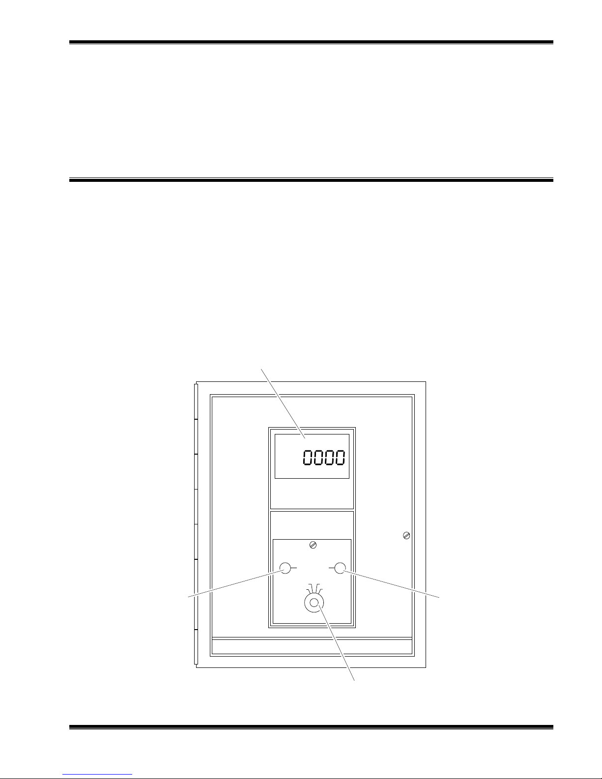
1.1 OVERVIEW
The Model 755A Oxygen Analyzer provides digital readout of the oxygen content of a
flowing gas sample. Oxygen is strongly paramagnetic; other common gases, with only
a few exceptions, are weakly diamagnetic.
A front panel liquid crystal display provides direct digital readout of oxygen
concentration. In addition a field-selectable voltage output is provided as standard.
An isolated current output of 0 to 20 mA or 4 to 20 mA is obtainable with the optional
Current Output Board. Current and voltage output may be utilized simultaneously if
desired.
6 Digit LCD Display
ZERO Adjust
F
IGURE
245364-U Rosemount Analytical April 2000
1-1. M
ODEL
755A O
ZERO
PRESS CAL1 PR ESS CA L 2
NORM R EC OF FSET
Rosemount Analytical
XYGEN ANALYZER
Model 755A
Oxygen Analyzer
TEST Switch
SPAN Adjust
Model 755A Oxygen Analyzer
1-1

NTRODUCTION
I
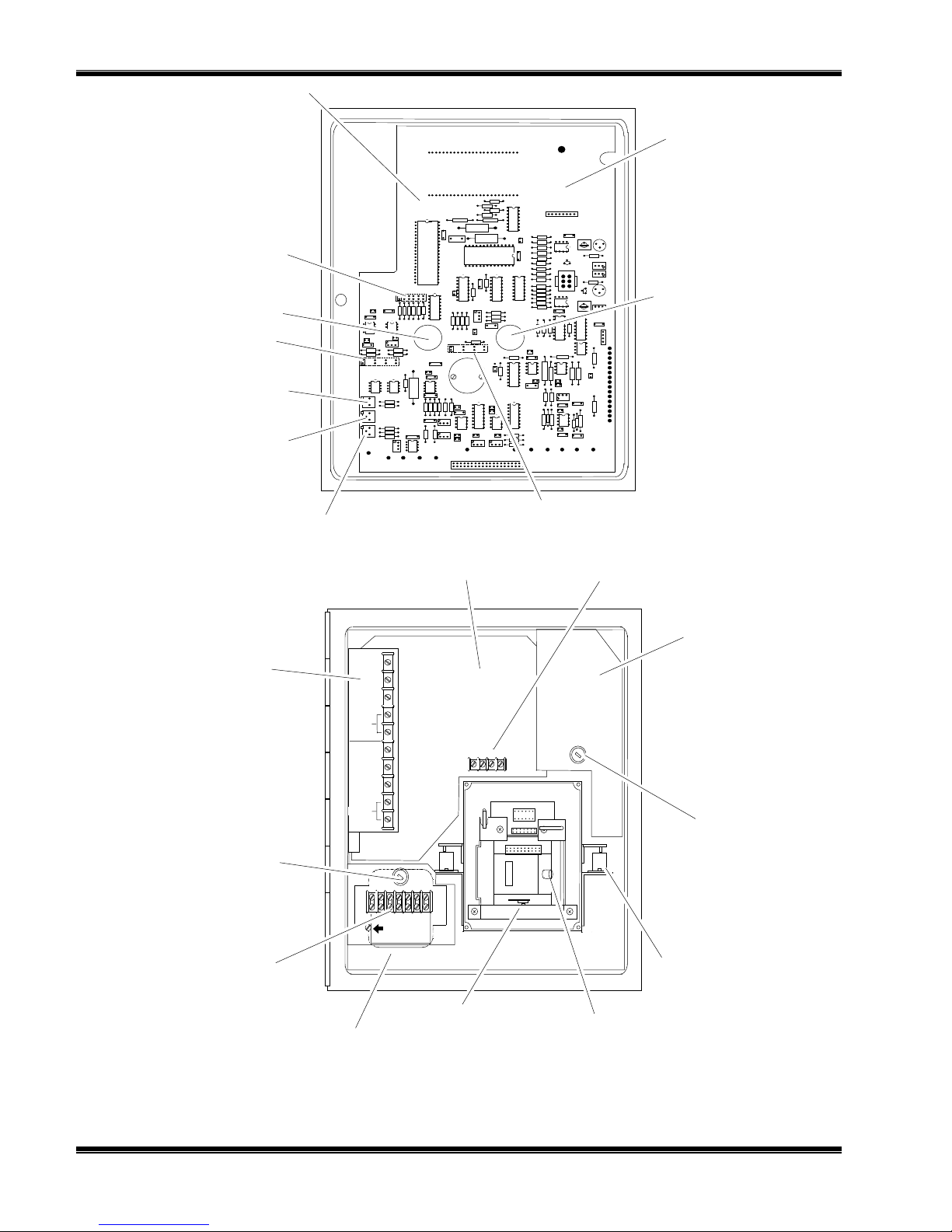
The basic electronic circuitry is incorporated into two master boards: The Control
Board Assembly and the Case Circuit Board Assembly (see Figure 1-2). The Control
Board has a receptacle which accepts optional circuit boards, thus permitting inclusion
of such features as current output.
1.2 OXYGEN RANGE ON FRONT PANEL DIGITAL DISPLAY
The front panel LCD (liquid crystal display) provides direct readout of oxygen
concentration from 0.00% to 100.00%.
1.3 OXYGEN RANGES FOR RECORDER READOUT
If desired, the recorder output may be set for a fullscale range of 0 to 100% oxygen.
Alternatively, a desired portion of this overall range may be selected for fullscale
presentation on the recorder. The selection is made by an appropriate combination of
scale expansion and zero suppression.
CALE EXPANSION
S
Fullscale oxygen span for the recorder is switch selectable for 1%, 2%, 5%, 10%,
20%, or 100% oxygen.
ERO SUPPRESSION
Z
The desired zero suppression is obtained as the sum of (a) a jumper selectable fixed
value of 0%, 20%, 40%, 60% or 80% oxygen and (b) a continuously adjustable value
of 0% to 25% oxygen. Thus the electronic circuitry provides the capability of setting
the total zero suppression for any desired value from 0% up to a theoretical maximum
of 105% oxygen.
However, the maximum usable zero suppression is 99%, which is used in establishing
a range of 99% to 100%.
The effective zero suppression, in volts, may be read on the digital display by placing
the front panel TEST Switch in position 4 and the Reorder Oxygen Span Selection
Switch in 1 X gain position (i.e., 100% oxygen)
Example:
Desired oxygen range for recorder output: 99% to 100% oxygen.
Required span is 1% oxygen, obtained by jumper position.
Required zero suppression is 99% oxygen. Thus, fixed zero suppression of 80%
oxygen is selected by jumper position, and adjustable zero suppression is set for
19% oxygen.
1-2
April 2000 Rosemount Analytical 245364-UModel 755A Oxygen Analyzer

1.4 RECORDER VOLTAGE AND CURRENT OUTPUTS
OLTAGE OUTPUTS (STANDA RD
V
Provided a standard is a jumper selectable voltage output of 0 to 10 mV, 0 to 100 mV,
0 to 1 V, or 0 to 5 V DC.
SOLATED CURRENT OUTPUT (OPTION
I
An isolated current output is obtainable with the optional Current Output Board, either
included with the Model 755A or added at a later date in the field.
This option provides a current output of either 0 to 20mA or 4 to 20mA for a maximum
of 850 ohms.
Refer to Section 8, Replacement Parts, for the part number of the Isolated Current
Output option.
)
)
NTRODUCTION
I
Note
Voltage and current outputs may be used simultaneously, if desired.
1.5 AUTOMATIC PRESSURE COMPENSATION
The oxygen readout is automatically corrected for pressure variations within 3% of the
target value, which may be set anywhere within the range of -2.7 to 3.3 psig ±3 psig (-
18.6 to 22.8 kPa ±21 kPa).
1.6 ALARM (OPTION)
The analyzer has an alarm relay assembly consisting of two single-pole, double-throw
relays, one each for the ALARM 1 and ALARM 2 contacts. These relays may be used
to drive external, customer-supplied alarm and/or control devices.
1.7 CASE MOUNTING OPTIONS
The analyzer is supplied, as ordered, with hardware for one of three mounting
arrangements: Panel, wall, or pipe stanchion.
1.8 ELECTRICAL POWER OPTIONS
The analyzer is supplied, as ordered, for operation on either 120 VAC, 50/60 Hz, or
240 VAC, 50/60 Hz.
245364-U Rosemount Analytical April 2000
Model 755A Oxygen Analyzer
1-3
NTRODUCTION
TB2
I
Control Board
Location for Optional
Current Output Board
Span Jumper Select
ZERO Control
SPAN Control
Recorder Output Jumper Select
Zero
Suppression
CAL2 Adjustment,
Pressure
Compensation
CAL1 Adjustment,
Pressure
Compensation
Alarm Relay Assembly
(Alarm Option)
Fuse
AC Power
NO. 1
RESE
NO. 2
RESET
COM
CO
Zero Offset Jumper Select
Recorder Output
Case Board
TB2
Case Heater
Assembly
NO
NC
NO
NC
-
+
HOT
Fuse
Case Heater
N
H
E
O
U
T
AC Power
TB1
Transformer, Power T1
(Behind TB1)
F
IGURE
1-2. M
ODEL
755A C
1-4
Detector/Magnet
Assembly Shock
Transducer
Mount
Detector/Magnet
Assembly
OMPONENTS AND ADJUSTMENTS LOCATIONS
April 2000 Rosemount Analytical 245364-UModel 755A Oxygen Analyzer

U
NPACKING AND INSTALLATION
2
2.1 UNPACKING
Carefully examine the shipping carton and contents for signs of damage. Immediately
notify the shipping carrier if the carton or its contents are damaged. Retain the carton
and packing materials until the instrument is operational.
2.2 LOCATION
2.2.1 L
2.3 VOLTAGE REQUIREMENTS
OCATION AND MOUNTING
The analyzer is designed to meet NEMA 3R enclosure requirements and may be
mounted outdoors. Permissible ambient temperature range is 20°F to 120°F (-7°C to
49°C).
Avoid mounting outside in direct sunlight, or inside in a closed building, where ambient
temperature may exceed the allowable maximum.
Shock and mechanical motion can reduce instrument accuracy; therefore, mount the
instrument in an area that is as vibration free as possible
WARNING: ELECTRICAL SHOCK HAZARD
Do not operate without doors and covers secure. Servicing requires access to
live parts which can cause death or serious injury. Refer servicing to qualified
personnel.
For safety and proper performance this instrument must be connected to a
properly grounded three-wire source of power.
Note
Refer to Installation Drawing 642349 at the rear of this manual for recommended
cable conduit openings.
245364-U Rosemount Analytical April 2000
Model 755A Oxygen Analyzer
2-1

NPACKING AND INSTALLATION
U
CAUTION: ENCLOSURE INTEGRITY
With reference to Installation Drawing 642349, any unused cable conduit
openings must be securely sealed by permanent closures in order to provide
enclosure integrity in compliance with personnel safety and environmental
protection requirements. The plastic closures provided are for shipping
protection only.
Note
For NEMA 3R service, all conduit must be connected through approved fittings.
This instrument was shipped from the factory configured to operate on 115 VAC or
240 VAC, 50/60 Hz electric power. Verify that the power source conforms to the
requirements of the individual instrument, as noted on the name-rating plate.
2.4 ELECTRICAL CONNECTIONS
2.4.1 L
2.4.2 R
INE POWER CONNECTIONS
Electrical power is supplied to the analyzer via a customer-supplied, three-conductor
cable, type SJT, minimum wire size 18 AWG. Route power cable through conduit and
into appropriate opening in the instrument case (see Installation Drawing 642349).
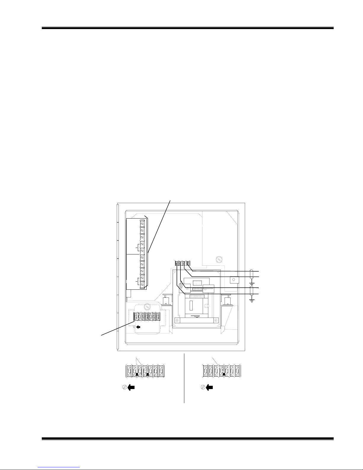
Connect power leads to HOT, NEUT, AND GND terminals on TB1, see Figure 2-1.
Connect analyzer to power source via an external fuse, in accordance with local
codes.
Note
Do not draw power for associated equipment from the analyzer power cable.
ECORDER CONNECTIONS
Note
Route recorder cable through a separate conduit, not with power cable or alarm
output cable.
If a recorder, controller, or other output device is used, connector it to the analyzer via
a 24-22 AWG two-conductor shielded cable.
Route the cable through conduit to the analyzer and into the case through the
appropriate opening shown in Installation Drawing 642349. Connect the shield only at
the recorder or computer, if used.
Cable connections and output selection for potentiometric and current actuated
2-2
April 2000 Rosemount Analytical 245364-UModel 755A Oxygen Analyzer
NPACKING AND INSTALLATION
GND
TB1
U
devices are explained in below.
OTENTIOMETRIC OUTPUT
P
Insert Recorder Output Selection Jumper, Figure 2-2, in position appropriate to the
desired output; 10 mV, 100 mV, 1V or 5V.
On TB2, Figure 2-1, connect leads of shielded recorder cable to "MV+" AND "COM"
terminals.
Connect free end of output cable to appropriate terminals of recorder or other
potentiometric device.
For device with a span of 0 to 10mV, 0 to 100mV, 0 to 1V, or 0 to 5V, connect cable
directly to input terminals of the device, making sure polarity is correct.
For device with intermediate span, i.e., between the specified values, connect cable to
device via a suitable external voltage divider, as shown in Figure 2-3.
Power Connections
(see below)
NO. 1
RESET
NO. 2
RESET
Jumpers
COM
COM
Optional Alarm Kit
NO
NC
NO
NC
N
H
E
O
U
T
T
COM
+ - +
TB2
Jumper
HOT
+
mV Recorder
-
+
mA Recorder
-
F
IGURE
2-1. E
LECTRICAL CONNECTIONS
245364-U Rosemount Analytical April 2000
TB1
N
GND GND
120 VAC CONFIGU RATION 240 VAC CONFIGU R AT ION
H
E
O
U
T
T
N
E
U
T
TB1
H
O
T
Model 755A Oxygen Analyzer
2-3

NPACKING AND INSTALLATION
U
Recorder Output Voltage
Selection Jumper
5V 1V 0.1V 0.01V
Control Board
R3
R4
R8
R9
CR2
1
2
3
4
C5
I
G
O
U5
I G O
I G O
R5
R6
U6
U3
U2
C4
C2
U4
C3 CR1 C1
R2 R1
U1
J1
Current Output
Board
F
IGURE
2-2. C
JP3
ONTROL BOARD
755A
Analyzer
Position of Recorder Output
Selector Plug
Voltage Divider
(Customer Supplied)
(Make sure polarity
is correct)
Minimum Permissible
Resistance for R1 + R2
10 mV 1K Ohm
100 mV 10K Ohm
1 V 100K Ohm
5 V 2K Ohm
Potentiometric
Recorder
Input
Terminals
F
IGURE
2-3. C
S
ONNECTIONS FOR POTENTIOMETRIC RECORDER WITH NON-STANDARD
PAN
2-4
April 2000 Rosemount Analytical 245364-UModel 755A Oxygen Analyzer
NPACKING AND INSTALLATION
U
SOLATED CURRENT OUTPUT (OPTIONAL
I
)
1. Verify that the Current Output Board appropriate to desired output is properly in
place. See Figure 2-2. If originally ordered with analyzer, the board is factory
installed.
2. On TB2, Figure 2-1, connect leads of shielded recorder cable to "MA+" and "-"
terminals.
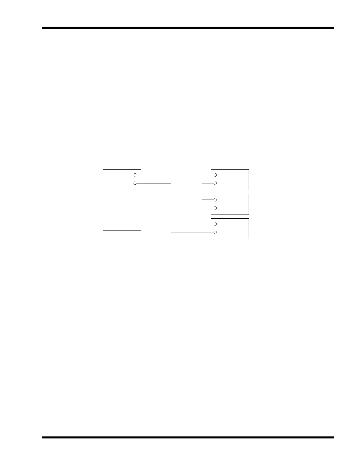
3. Connect free end of output cable to input terminals of recorder or other current
actuated device, making sure that polarity is correct. If two or more currentactuated devices are to be used, they must be connected in series as shown in
Figure 2-4.
Total resistance of all output devices and associated interconnection cable must not
exceed 850 ohms.
Current and voltage outputs may be utilized simultaneously, if desired.
+
Recorder
-
+
Controller
-
+
Indicator
Remote
F
IGURE
2.4.3 O
+
mA
-
755A
Analyzer
2-4. M
O
ODEL
UTPUT DEVICES
755A C
ONNECTED TO DRIVE SEVERAL CURRENT-ACTIVATED
UTPUT CONNECTIONS FOR DUAL ALARM OPTION
If so ordered, the analyzer is factory-equipped with alarm output. Alternatively, the
alarm feature is obtainable by subsequent installation of the 618083 Alarm Relay Kit.
LARM OUTPUT CONNECTIONS
A
The alarm output provides two sets of relay contacts for actuation of alarm and/or
process control functions. Leads from the (customer-supplied) external alarm system
connect to terminals on the 638254 Alarm Relay Assembly (see Figure 2-1).
Note the following recommendations:
1. A line fuse should be installed in the line between the (customer-supplied) power
supply and the alarm relay terminals on the Alarm Relay Assembly.
2. If the alarm contacts are connected to any device that produces radio frequency
interference (RFI), it should be arc-suppressed. Rosemount Analytical Arc
Suppression (PN 858728) is recommended.
3. If possible, the analyzer should operate on a different AC power source to avoid
RFI.
245364-U Rosemount Analytical April 2000
Model 755A Oxygen Analyzer
2-5

NPACKING AND INSTALLATION
U
4. Do not allow internal cable service loop to touch the detector assembly or
associated inlet and outlet tubing. This precaution ensures against possible
transmission of mechanical vibration through the cable to the detector, which can
cause loss of accuracy.
LARM RELAY CHARACTERISTICS
A
The ALARM 1 and ALARM 2. Outputs of the Alarm Relay Assembly are provided by
two identical single-pole double-throw relays. Relay contacts are rated:
5 amperes 240 VAC resistive
1 ampere 240 VAC inductive
5 amperes 120 VAC resistive
3 amperes 120 VAC inductive
5 amperes 30 VDC resistive
3 amperes 30 VDC inductive
Removal of AC power from the analyzer, as in a power failure, de-energizes both
relays, placing them in alarm condition. Switching characteristics of the ALARM 1 and
ALARM 2 relays are as follows:
ALARM 1 Relay - The ALARM 1 relay coil is de-energized when the meter needle
moves downscale through the value that corresponds to setpoint minus deadband.
This relay coil is energized when the needle moves upscale through the value that
corresponds to setpoint plus deadband. See Figure 2-5A.
ALARM 2 Relay - The ALARM 2 relay coil is de-energized when the meter needle
moves upscale through the value that corresponds to the setpoint plus deadband.
This relay coil is energized when needle moves downscale through the value that
corresponds to setpoint minus deadband. See Figure 2-5B.
Alarm Reset - Normally both the ALARM 1 and ALARM 2 functions incorporate
automatic reset. When the meter reading goes beyond the pre-selected limits, the
corresponding relay is de-energized. When the meter reading returns within the
acceptable range, the relay is automatically substituting an external pushbutton or
other momentary-contact switch for the jumper that normally connects the RESET
terminals on the Alarm Relay Assembly. If the corresponding relay is now deenergized, i.e., in alarm condition, the relay remains de-energized until the operator
momentarily closes the switch.
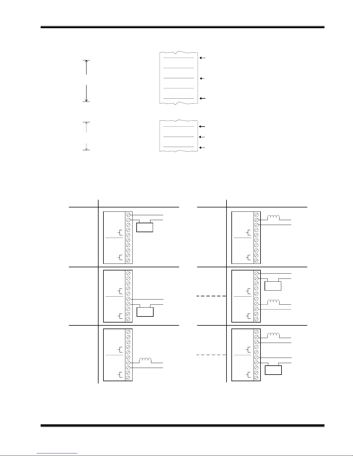
Fail-Safe Applications - By appropriate connection to the double-throw relay
contacts, it is possible to obtain either a contact closure or a contact opening for an
energized relay. Also, either a contact closure or a contact opening may be obtained
for a de-energized relay.
It is important that, for fail-safe applications, the user understand wheat circuit
conditions are desired in the event of power failure and the resultant relay deenergization. Relay contacts should then be connected accordingly. Refer to Figure
2-6.
2-6
April 2000 Rosemount Analytical 245364-UModel 755A Oxygen Analyzer
NPACKING AND INSTALLATION
U
A. Typical ALARM 1 Setting
DEADBAND SET FOR
20% OF FULLSCALE
B. Typical ALARM 2 Setting
DEADBAND SET FOR
10% OF FULLSCALE
F
IGURE
2-5. T
Low Alarm,
Fail-Safe
40
INPUT SIGNAL
Percent of Fullscale
30
20
55
INPUT SIGNAL
Percent of Fullscale
50
45
YPICAL ALARM SETTINGS
No. 1
RESET
RESET
No. 2
COM
COM
NO
NC
NO
NC
Alarm Bell
or Lamp
115 VAC
N
H
When input signal moves upscale through this point, the coil of
ALARM 1 relay (K1) is energized, providing continuity between the
common and normally-closed contacts of the relay.
ALARM 1 Setpoint
When input signal moves downscale through this point, the coil of
ALARM 1 relay (K1) is de-energized, providing continuity between the
common and normally-open contacts of the relay.
When input signal moves upscale through this point, the coil of ALARM
2 relay (K2) is de-energized, providing continuity between the common
and normally-open contacts of the relay.
ALARM 2 Setpoint
When input signal moves upscale through this point, the coil of ALARM
2 relay (K2) is energized, providing continuity between the common
and normally-closed contacts of the relay.
REQUIREMENT TYPICAL CONNECTIONSREQUIREMENT TYPICAL CONNECTIONS
Solenoid
Valve
115 VAC
Low Control
Limit,
Fail-Safe
No. 1
RESET
RESET
No. 2
NO
COM
NC
NO
COM
NC
H
N
No. 1
NO
COM
NC
RESET
NO
COM
RESET
No. 2
No. 1
RESET
RESET
No. 2
NC
NO
COM
NC
NO
COM
NC
Alarm Bell
or Lamp
Solenoid
Valve
ELAY TERMINAL CONNECTIONS FOR TYPICAL FAIL-SAFE APPLICATION
F
IGURE
High Alarm,
Fail-Safe
Low Control
Limit,
Fail-Safe
2-6. R
245364-U Rosemount Analytical April 2000
115 VAC
115 VAC
No. 1
RESET
RESET
No. 2
No. 1
RESET
RESET
No. 2
COM
COM
COM
COM
NO
NC
NO
NC
NO
NC
NO
NC
Alarm Bell
or Lamp
Solenoid
Valve
Solenoid
Valve
Alarm Bell
or Lamp
Lower
Low Alarm
Indicator,
Fail-Safe
N
H
H
N
Low Control,
Fail-Safe
High Control,
Fail-Safe
Higher
High Alarm
Indicator,
Fail-Safe
Model 755A Oxygen Analyzer
115 VAC
115 VAC
115 VAC
115 VAC
N
H
H
N
H
N
N
H
2-7

NPACKING AND INSTALLATION
U
2.5 CALIBRATION GASES
2.5.1 Z
2.5.2 D
2.5.3 U
ERO CALIBRATION GAS
Zero-based range - Normally uses a oxygen-free gas, typically nitrogen.
Zero-suppressed range - Uses a blend consisting of a suitable percentage of oxygen
contained in a background gas, typically nitrogen.
OWNSCALE STANDA RD GAS
Digital Display - Typically, although not necessarily, the downscale standard gas will
be oxygen-free, such as nitrogen.
Recorder Readout - The downscale standard gas is selected to establish a
calibration point at or near the lower range limit.
PSCALE STANDA RD GAS
Digital Display - Typically, the upscale standard gas will be a readily obtained gas
such as dry air (20.93% oxygen) or 1005 oxygen.
Recorder Readout - A suitable upscale standard gas is required to establish a
calibration point at or near the upper range limit. If this range limit is 21% or
somewhat above 21%, the usual standard gas is dry air (20.93% oxygen).
2.6 SAMPLE HANDLING
CAUTION: PRESSURE LIMIT
Under no circumstances allow pressure to exceed 10 psig (69 kPa) as
irreparable damage to the detector may result.
Many different sample handling systems are available, depending on the requirements
of the individual user. Most sample handling systems have copper or brass
components; however, stainless steel components are available for applications
involving corrosive gases. With corrosive gases, complete drying of the sample is
desirable, as most of these gases are practically inert when totally dry.
For specific corrosive applications, consult the factory.
2.6.1 S
AMPLE TEMPERATURE REQUIREMENTS
Sample temperature at the analyzer inlet should be in the range of 50°V to 150°F
(10°C to 66°C). W ith a thoroughly dry sample, entry temperature can be as high as
150°F (66°C) without affecting readout accuracy. Normally, a maximum entry
temperature of 110°F (43°C) is recommended so that the sample temperature will rise
2-8
April 2000 Rosemount Analytical 245364-UModel 755A Oxygen Analyzer
NPACKING AND INSTALLATION
U
during passage of the sample through the analyzer. This precaution ensures against
cooling of the sample and possible condensation of moisture. Such condensation
should be avoided as it may damage the detector.
2.6.2. S
AMPLE PRESSURE REQUIREMENTS
: G
ENERAL
Operating pressure limits are the following: maximum, 10 psig (69 kPa gauge
pressure); minimum, -1.9 psig (-13.1 kPa).
CAUTION: OPERATIN G LI MITS
Operation outside the specified limits may damage the detector and will void the
warranty.
Oxygen readout is automatically corrected for atmospheric pressure variations within
±3% of the target value, which may be set anywhere within the range of -2.7 to 3.3
psig ±3 psig (-18.6 to 22.8 kPa ±21 kPa).
The basic rule for pressure of sample and standard gases supplied to the inlet is to
calibrate the analyzer at the same pressure that will be used during subsequent
operation and to maintain this pressure during operation. The arrangement required
to obtain appropriate pressure control will depend on the application. Refer to special
instructions included in Section 2.6.3, Normal Operation at Positive Gauge Pressures;
or Section 2.6.4, Operation at Negative Gauge Pressures.
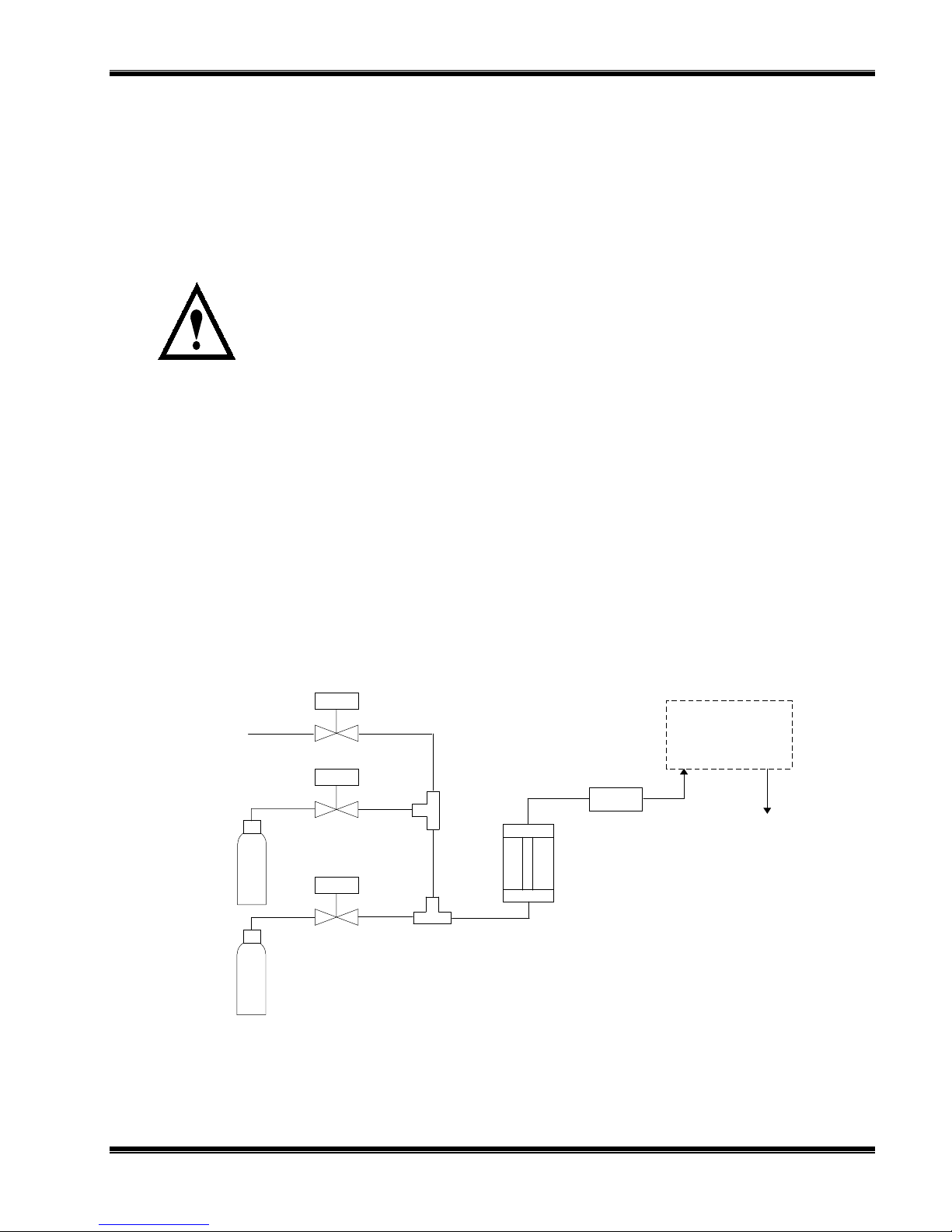
F
IGURE
Sample In
Downscale
Standard
Gas
Upscale
Standard
Gas
2-7. C
Needle
Valves
Two Micron
Flowmeter
Filter
Model 755A
Oxygen Analyzer
ONNECTION OF TYPICAL GAS SELECTOR PANEL TO MODEL
O
XYGEN ANALYZER
To Vent
755A
245364-U Rosemount Analytical April 2000
Model 755A Oxygen Analyzer
2-9
 Loading...