

Page 1
Rosemount™ 5400 Level Transmitter
Two-Wire Non-Contacting Radar
Reference Manual
00809-0100-4026, Rev KB
June 2016
Page 2

Page 3

Reference Manual
00809-0100-4026, Rev KB
Contents
1Section 1: Introduction
2Section 2: Transmitter Overview
Contents
June 2016
1.1 Using this manual . . . . . . . . . . . . . . . . . . . . . . . . . . . . . . . . . . . . . . . . . . . . . . . . . . . . . . . . . . . . . . . . . 1
1.2 Product recycling/disposal. . . . . . . . . . . . . . . . . . . . . . . . . . . . . . . . . . . . . . . . . . . . . . . . . . . . . . . . . . 1
2.1 Theory of operation. . . . . . . . . . . . . . . . . . . . . . . . . . . . . . . . . . . . . . . . . . . . . . . . . . . . . . . . . . . . . . . . 3
2.2 Application examples . . . . . . . . . . . . . . . . . . . . . . . . . . . . . . . . . . . . . . . . . . . . . . . . . . . . . . . . . . . . . . 4
2.3 System architecture . . . . . . . . . . . . . . . . . . . . . . . . . . . . . . . . . . . . . . . . . . . . . . . . . . . . . . . . . . . . . . . 6
2.4 Process characteristics . . . . . . . . . . . . . . . . . . . . . . . . . . . . . . . . . . . . . . . . . . . . . . . . . . . . . . . . . . . . . 8
2.5 Components of the transmitter . . . . . . . . . . . . . . . . . . . . . . . . . . . . . . . . . . . . . . . . . . . . . . . . . . . . 10
2.6 Antenna selection guide/measuring range. . . . . . . . . . . . . . . . . . . . . . . . . . . . . . . . . . . . . . . . . . . 11
3Section 3: Mechanical Installation
3.1 Safety messages. . . . . . . . . . . . . . . . . . . . . . . . . . . . . . . . . . . . . . . . . . . . . . . . . . . . . . . . . . . . . . . . . . 15
3.2 Installation procedure. . . . . . . . . . . . . . . . . . . . . . . . . . . . . . . . . . . . . . . . . . . . . . . . . . . . . . . . . . . . . 17
3.3 Mounting considerations . . . . . . . . . . . . . . . . . . . . . . . . . . . . . . . . . . . . . . . . . . . . . . . . . . . . . . . . . . 18
3.3.1 Mounting location . . . . . . . . . . . . . . . . . . . . . . . . . . . . . . . . . . . . . . . . . . . . . . . . . . . . . . . . . . 18
3.3.2 Special considerations in solids applications . . . . . . . . . . . . . . . . . . . . . . . . . . . . . . . . . . . . 20
3.3.3 Mounting in pipes. . . . . . . . . . . . . . . . . . . . . . . . . . . . . . . . . . . . . . . . . . . . . . . . . . . . . . . . . . . 21
3.3.4 Condensation conditions . . . . . . . . . . . . . . . . . . . . . . . . . . . . . . . . . . . . . . . . . . . . . . . . . . . . 22
3.3.5 Nozzle considerations . . . . . . . . . . . . . . . . . . . . . . . . . . . . . . . . . . . . . . . . . . . . . . . . . . . . . . . 23
3.3.6 Nozzle recommendations and requirements . . . . . . . . . . . . . . . . . . . . . . . . . . . . . . . . . . . 27
3.3.7 Service space . . . . . . . . . . . . . . . . . . . . . . . . . . . . . . . . . . . . . . . . . . . . . . . . . . . . . . . . . . . . . . . 31
3.3.8 Beam width . . . . . . . . . . . . . . . . . . . . . . . . . . . . . . . . . . . . . . . . . . . . . . . . . . . . . . . . . . . . . . . . 32
3.3.9 Vessel characteristics. . . . . . . . . . . . . . . . . . . . . . . . . . . . . . . . . . . . . . . . . . . . . . . . . . . . . . . . 34
3.3.10Disturbing objects . . . . . . . . . . . . . . . . . . . . . . . . . . . . . . . . . . . . . . . . . . . . . . . . . . . . . . . . . . 34
3.3.11Valves . . . . . . . . . . . . . . . . . . . . . . . . . . . . . . . . . . . . . . . . . . . . . . . . . . . . . . . . . . . . . . . . . . . . . 34
3.4 Mounting. . . . . . . . . . . . . . . . . . . . . . . . . . . . . . . . . . . . . . . . . . . . . . . . . . . . . . . . . . . . . . . . . . . . . . . . 35
3.4.1 Cone antenna with flange connection . . . . . . . . . . . . . . . . . . . . . . . . . . . . . . . . . . . . . . . . . 35
3.4.2 Cone antenna with threaded tank connection . . . . . . . . . . . . . . . . . . . . . . . . . . . . . . . . . . 36
Content s
3.4.3 Cone antenna with threaded tank connection and customer supplied flange. . . . . . . 38
3.4.4 Process seal antenna with flange. . . . . . . . . . . . . . . . . . . . . . . . . . . . . . . . . . . . . . . . . . . . . . 46
3.4.5 Parabolic antenna with flange . . . . . . . . . . . . . . . . . . . . . . . . . . . . . . . . . . . . . . . . . . . . . . . . 48
3.4.6 Parabolic antenna with welded connection . . . . . . . . . . . . . . . . . . . . . . . . . . . . . . . . . . . . 50
3.4.7 Parabolic antenna with threaded connection . . . . . . . . . . . . . . . . . . . . . . . . . . . . . . . . . . . 57
iii
Page 4

Contents
June 2016
Reference Manual
00809-0100-4026, Rev KB
3.4.8 Adjust inclination of parabolic antenna . . . . . . . . . . . . . . . . . . . . . . . . . . . . . . . . . . . . . . . . 63
3.4.9 Rod antenna with threaded connection. . . . . . . . . . . . . . . . . . . . . . . . . . . . . . . . . . . . . . . . 67
3.4.10Rod antenna with flanged connection . . . . . . . . . . . . . . . . . . . . . . . . . . . . . . . . . . . . . . . . . 68
3.4.11Tri Clamp tank connection . . . . . . . . . . . . . . . . . . . . . . . . . . . . . . . . . . . . . . . . . . . . . . . . . . . 69
3.4.12Bracket mounting . . . . . . . . . . . . . . . . . . . . . . . . . . . . . . . . . . . . . . . . . . . . . . . . . . . . . . . . . . 70
4Section 4: Electrical Installation
4.1 Safety messages. . . . . . . . . . . . . . . . . . . . . . . . . . . . . . . . . . . . . . . . . . . . . . . . . . . . . . . . . . . . . . . . . . 71
4.2 Wiring and power supply requirements . . . . . . . . . . . . . . . . . . . . . . . . . . . . . . . . . . . . . . . . . . . . . 73
4.3 Cable/conduit entries . . . . . . . . . . . . . . . . . . . . . . . . . . . . . . . . . . . . . . . . . . . . . . . . . . . . . . . . . . . . . 73
4.4 Grounding. . . . . . . . . . . . . . . . . . . . . . . . . . . . . . . . . . . . . . . . . . . . . . . . . . . . . . . . . . . . . . . . . . . . . . . 73
4.5 Cable selection . . . . . . . . . . . . . . . . . . . . . . . . . . . . . . . . . . . . . . . . . . . . . . . . . . . . . . . . . . . . . . . . . . . 74
4.6 Hazardous areas. . . . . . . . . . . . . . . . . . . . . . . . . . . . . . . . . . . . . . . . . . . . . . . . . . . . . . . . . . . . . . . . . . 74
4.7 External circuit breaker. . . . . . . . . . . . . . . . . . . . . . . . . . . . . . . . . . . . . . . . . . . . . . . . . . . . . . . . . . . . 74
4.8 Connecting the transmitter . . . . . . . . . . . . . . . . . . . . . . . . . . . . . . . . . . . . . . . . . . . . . . . . . . . . . . . . 75
4.9 HART
®
communication . . . . . . . . . . . . . . . . . . . . . . . . . . . . . . . . . . . . . . . . . . . . . . . . . . . . . . . . . . . 78
4.9.1 Power requirements . . . . . . . . . . . . . . . . . . . . . . . . . . . . . . . . . . . . . . . . . . . . . . . . . . . . . . . . 78
4.9.2 Load limitations . . . . . . . . . . . . . . . . . . . . . . . . . . . . . . . . . . . . . . . . . . . . . . . . . . . . . . . . . . . . 78
4.9.3 Non-intrinsically safe power supply . . . . . . . . . . . . . . . . . . . . . . . . . . . . . . . . . . . . . . . . . . . 80
4.9.4 Intrinsically safe power supply . . . . . . . . . . . . . . . . . . . . . . . . . . . . . . . . . . . . . . . . . . . . . . . . 81
4.9.5 Type N approvals: non-sparking / energy-limited power supply . . . . . . . . . . . . . . . . . . . 82
4.9.6 Transient protection terminal block . . . . . . . . . . . . . . . . . . . . . . . . . . . . . . . . . . . . . . . . . . . 82
4.10F
OUNDATION Fieldbus . . . . . . . . . . . . . . . . . . . . . . . . . . . . . . . . . . . . . . . . . . . . . . . . . . . . . . . . . . . . . . 83
4.10.1Power requirements . . . . . . . . . . . . . . . . . . . . . . . . . . . . . . . . . . . . . . . . . . . . . . . . . . . . . . . . 83
4.10.2Non-intrinsically safe power supply . . . . . . . . . . . . . . . . . . . . . . . . . . . . . . . . . . . . . . . . . . . 85
4.10.3Intrinsically safe power supply. . . . . . . . . . . . . . . . . . . . . . . . . . . . . . . . . . . . . . . . . . . . . . . . 86
4.10.4Type N approvals: non-sparking / energy-limited power supply. . . . . . . . . . . . . . . . . . . 87
4.11HART to Modbus Converter (HMC) . . . . . . . . . . . . . . . . . . . . . . . . . . . . . . . . . . . . . . . . . . . . . . . . . 88
4.11.1Connecting the transmitter . . . . . . . . . . . . . . . . . . . . . . . . . . . . . . . . . . . . . . . . . . . . . . . . . . 88
4.11.2Connection terminals . . . . . . . . . . . . . . . . . . . . . . . . . . . . . . . . . . . . . . . . . . . . . . . . . . . . . . . 90
4.11.3RS-485 bus. . . . . . . . . . . . . . . . . . . . . . . . . . . . . . . . . . . . . . . . . . . . . . . . . . . . . . . . . . . . . . . . . 91
4.11.4Installation cases . . . . . . . . . . . . . . . . . . . . . . . . . . . . . . . . . . . . . . . . . . . . . . . . . . . . . . . . . . . 91
4.11.5External HART devices (slaves) . . . . . . . . . . . . . . . . . . . . . . . . . . . . . . . . . . . . . . . . . . . . . . . 93
4.12Establish HART communication . . . . . . . . . . . . . . . . . . . . . . . . . . . . . . . . . . . . . . . . . . . . . . . . . . . . 94
4.12.1Connect to the MA/MB terminals . . . . . . . . . . . . . . . . . . . . . . . . . . . . . . . . . . . . . . . . . . . . . 94
4.12.2Connect to the HART terminals. . . . . . . . . . . . . . . . . . . . . . . . . . . . . . . . . . . . . . . . . . . . . . . 96
4.13Optional devices . . . . . . . . . . . . . . . . . . . . . . . . . . . . . . . . . . . . . . . . . . . . . . . . . . . . . . . . . . . . . . . . . 97
4.13.1Tri-Loop™ HART to analog converter. . . . . . . . . . . . . . . . . . . . . . . . . . . . . . . . . . . . . . . . . . 97
iv
Contents
Page 5

Reference Manual
00809-0100-4026, Rev KB
5Section 5: Basic Configuration/Start-up
Contents
June 2016
4.13.2751 Field Signal Indicator . . . . . . . . . . . . . . . . . . . . . . . . . . . . . . . . . . . . . . . . . . . . . . . . . . . . 97
4.13.3Emerson
5.1 Safety messages. . . . . . . . . . . . . . . . . . . . . . . . . . . . . . . . . . . . . . . . . . . . . . . . . . . . . . . . . . . . . . . . . . 99
5.2 Overview . . . . . . . . . . . . . . . . . . . . . . . . . . . . . . . . . . . . . . . . . . . . . . . . . . . . . . . . . . . . . . . . . . . . . . . 100
5.2.1 Basic configuration parameters . . . . . . . . . . . . . . . . . . . . . . . . . . . . . . . . . . . . . . . . . . . . . .100
5.2.2 Configuration tools . . . . . . . . . . . . . . . . . . . . . . . . . . . . . . . . . . . . . . . . . . . . . . . . . . . . . . . . 100
5.3 Basic configuration parameters . . . . . . . . . . . . . . . . . . . . . . . . . . . . . . . . . . . . . . . . . . . . . . . . . . . 101
5.3.1 Measurement units . . . . . . . . . . . . . . . . . . . . . . . . . . . . . . . . . . . . . . . . . . . . . . . . . . . . . . . .101
5.3.2 Tank geometry . . . . . . . . . . . . . . . . . . . . . . . . . . . . . . . . . . . . . . . . . . . . . . . . . . . . . . . . . . . . 101
5.3.3 Process conditions . . . . . . . . . . . . . . . . . . . . . . . . . . . . . . . . . . . . . . . . . . . . . . . . . . . . . . . . . 103
5.3.4 Volume configuration . . . . . . . . . . . . . . . . . . . . . . . . . . . . . . . . . . . . . . . . . . . . . . . . . . . . . .104
5.3.5 Analog output (HART) . . . . . . . . . . . . . . . . . . . . . . . . . . . . . . . . . . . . . . . . . . . . . . . . . . . . . . 107
™
Smart Wireless THUM™ Adapter . . . . . . . . . . . . . . . . . . . . . . . . . . . . . . . . . . . . 98
5.3.6 Level and distance calibration . . . . . . . . . . . . . . . . . . . . . . . . . . . . . . . . . . . . . . . . . . . . . . . 108
5.3.7 Echo tuning . . . . . . . . . . . . . . . . . . . . . . . . . . . . . . . . . . . . . . . . . . . . . . . . . . . . . . . . . . . . . . . 109
5.3.8 ATC . . . . . . . . . . . . . . . . . . . . . . . . . . . . . . . . . . . . . . . . . . . . . . . . . . . . . . . . . . . . . . . . . . . . . . 110
5.4 Basic configuration using RRM . . . . . . . . . . . . . . . . . . . . . . . . . . . . . . . . . . . . . . . . . . . . . . . . . . . . 110
5.4.1 System requirements . . . . . . . . . . . . . . . . . . . . . . . . . . . . . . . . . . . . . . . . . . . . . . . . . . . . . . 110
5.4.2 Help in RRM . . . . . . . . . . . . . . . . . . . . . . . . . . . . . . . . . . . . . . . . . . . . . . . . . . . . . . . . . . . . . . . 111
5.4.3 Installing the RRM software for HART communication . . . . . . . . . . . . . . . . . . . . . . . . . . 111
5.4.4 Specifying the COM port . . . . . . . . . . . . . . . . . . . . . . . . . . . . . . . . . . . . . . . . . . . . . . . . . . . .112
5.4.5 To set the COM port buffers . . . . . . . . . . . . . . . . . . . . . . . . . . . . . . . . . . . . . . . . . . . . . . . . . 113
5.4.6 Specifying measurement units . . . . . . . . . . . . . . . . . . . . . . . . . . . . . . . . . . . . . . . . . . . . . . 113
5.4.7 Installing the RRM software for F
OUNDATION Fieldbus . . . . . . . . . . . . . . . . . . . . . . . . . . . 113
5.4.8 Specifying measurement units . . . . . . . . . . . . . . . . . . . . . . . . . . . . . . . . . . . . . . . . . . . . . . 115
5.4.9 Using the Setup functions. . . . . . . . . . . . . . . . . . . . . . . . . . . . . . . . . . . . . . . . . . . . . . . . . . . 116
5.4.10Guided setup. . . . . . . . . . . . . . . . . . . . . . . . . . . . . . . . . . . . . . . . . . . . . . . . . . . . . . . . . . . . . . 117
5.4.11Using the Setup functions . . . . . . . . . . . . . . . . . . . . . . . . . . . . . . . . . . . . . . . . . . . . . . . . . . 128
5.5 Configuration using a Field Communicator . . . . . . . . . . . . . . . . . . . . . . . . . . . . . . . . . . . . . . . . .129
5.6 Basic configuration using AMS Suite . . . . . . . . . . . . . . . . . . . . . . . . . . . . . . . . . . . . . . . . . . . . . . .133
5.7 Configuration using DeltaV . . . . . . . . . . . . . . . . . . . . . . . . . . . . . . . . . . . . . . . . . . . . . . . . . . . . . . . 134
5.7.1 Advanced configuration . . . . . . . . . . . . . . . . . . . . . . . . . . . . . . . . . . . . . . . . . . . . . . . . . . . . 139
5.8 F
OUNDATION Fieldbus overview. . . . . . . . . . . . . . . . . . . . . . . . . . . . . . . . . . . . . . . . . . . . . . . . . . . . . 140
Content s
5.8.1 Assigning device tag and node address . . . . . . . . . . . . . . . . . . . . . . . . . . . . . . . . . . . . . . . 141
5.8.2 Foundation Fieldbus block operation . . . . . . . . . . . . . . . . . . . . . . . . . . . . . . . . . . . . . . . . . 141
5.9 Application examples . . . . . . . . . . . . . . . . . . . . . . . . . . . . . . . . . . . . . . . . . . . . . . . . . . . . . . . . . . . . 143
5.9.1 Radar level transmitter - level value . . . . . . . . . . . . . . . . . . . . . . . . . . . . . . . . . . . . . . . . . . 143
v
Page 6

Contents
June 2016
Reference Manual
00809-0100-4026, Rev KB
5.9.2 Radar level transmitter - level value in percent (%). . . . . . . . . . . . . . . . . . . . . . . . . . . . . . 144
5.10Tri-Loop™ HART to Analog Converter . . . . . . . . . . . . . . . . . . . . . . . . . . . . . . . . . . . . . . . . . . . . . . 145
5.11HART multidrop configuration . . . . . . . . . . . . . . . . . . . . . . . . . . . . . . . . . . . . . . . . . . . . . . . . . . . . 147
6Section 6: Operation
6.1 Safety messages. . . . . . . . . . . . . . . . . . . . . . . . . . . . . . . . . . . . . . . . . . . . . . . . . . . . . . . . . . . . . . . . . 149
6.2 Viewing measurement data. . . . . . . . . . . . . . . . . . . . . . . . . . . . . . . . . . . . . . . . . . . . . . . . . . . . . . . 151
6.2.1 Using the display panel . . . . . . . . . . . . . . . . . . . . . . . . . . . . . . . . . . . . . . . . . . . . . . . . . . . . .151
6.2.2 Specifying display panel variables . . . . . . . . . . . . . . . . . . . . . . . . . . . . . . . . . . . . . . . . . . . . 151
6.2.3 Viewing measurement data in RRM . . . . . . . . . . . . . . . . . . . . . . . . . . . . . . . . . . . . . . . . . . 154
6.2.4 Viewing measurement data in AMS Suite and DeltaV . . . . . . . . . . . . . . . . . . . . . . . . . . . 156
6.3 LCD display error messages . . . . . . . . . . . . . . . . . . . . . . . . . . . . . . . . . . . . . . . . . . . . . . . . . . . . . . . 157
6.4 LED error messages . . . . . . . . . . . . . . . . . . . . . . . . . . . . . . . . . . . . . . . . . . . . . . . . . . . . . . . . . . . . . .158
7Section 7: Service and Troubleshooting
7.1 Safety messages. . . . . . . . . . . . . . . . . . . . . . . . . . . . . . . . . . . . . . . . . . . . . . . . . . . . . . . . . . . . . . . . . 159
7.2 Troubleshooting overview . . . . . . . . . . . . . . . . . . . . . . . . . . . . . . . . . . . . . . . . . . . . . . . . . . . . . . . . 161
7.3 Service overview . . . . . . . . . . . . . . . . . . . . . . . . . . . . . . . . . . . . . . . . . . . . . . . . . . . . . . . . . . . . . . . . 162
7.3.1 Analyzing the measurement signal. . . . . . . . . . . . . . . . . . . . . . . . . . . . . . . . . . . . . . . . . . . 162
7.3.2 Surface pulse not found . . . . . . . . . . . . . . . . . . . . . . . . . . . . . . . . . . . . . . . . . . . . . . . . . . . . 163
7.3.3 Registration of false echoes . . . . . . . . . . . . . . . . . . . . . . . . . . . . . . . . . . . . . . . . . . . . . . . . . 164
7.3.4 Using the Echo Curve Analyzer . . . . . . . . . . . . . . . . . . . . . . . . . . . . . . . . . . . . . . . . . . . . . . 166
7.3.5 Using the Echo Curve Analyzer with a Field Communicator. . . . . . . . . . . . . . . . . . . . . . 169
7.4 Analog output calibration . . . . . . . . . . . . . . . . . . . . . . . . . . . . . . . . . . . . . . . . . . . . . . . . . . . . . . . . 171
7.5 Logging measurement data. . . . . . . . . . . . . . . . . . . . . . . . . . . . . . . . . . . . . . . . . . . . . . . . . . . . . . . 172
7.6 Backing up the transmitter configuration . . . . . . . . . . . . . . . . . . . . . . . . . . . . . . . . . . . . . . . . . . .173
7.7 Diagnostics . . . . . . . . . . . . . . . . . . . . . . . . . . . . . . . . . . . . . . . . . . . . . . . . . . . . . . . . . . . . . . . . . . . . . 174
7.8 Configuration report . . . . . . . . . . . . . . . . . . . . . . . . . . . . . . . . . . . . . . . . . . . . . . . . . . . . . . . . . . . . .175
7.9 Viewing input and holding registers. . . . . . . . . . . . . . . . . . . . . . . . . . . . . . . . . . . . . . . . . . . . . . . . 176
7.10Reset to factory settings . . . . . . . . . . . . . . . . . . . . . . . . . . . . . . . . . . . . . . . . . . . . . . . . . . . . . . . . . 177
7.11Surface search . . . . . . . . . . . . . . . . . . . . . . . . . . . . . . . . . . . . . . . . . . . . . . . . . . . . . . . . . . . . . . . . . . 178
7.12Using the Simulation Mode . . . . . . . . . . . . . . . . . . . . . . . . . . . . . . . . . . . . . . . . . . . . . . . . . . . . . . . 179
7.13Write protecting a transmitter . . . . . . . . . . . . . . . . . . . . . . . . . . . . . . . . . . . . . . . . . . . . . . . . . . . . 180
7.14Diagnostic messages . . . . . . . . . . . . . . . . . . . . . . . . . . . . . . . . . . . . . . . . . . . . . . . . . . . . . . . . . . . . 181
7.14.1Troubleshooting. . . . . . . . . . . . . . . . . . . . . . . . . . . . . . . . . . . . . . . . . . . . . . . . . . . . . . . . . . . 181
7.14.2Device status. . . . . . . . . . . . . . . . . . . . . . . . . . . . . . . . . . . . . . . . . . . . . . . . . . . . . . . . . . . . . . 181
7.14.3Errors . . . . . . . . . . . . . . . . . . . . . . . . . . . . . . . . . . . . . . . . . . . . . . . . . . . . . . . . . . . . . . . . . . . . 182
7.14.4Warnings . . . . . . . . . . . . . . . . . . . . . . . . . . . . . . . . . . . . . . . . . . . . . . . . . . . . . . . . . . . . . . . . . 183
vi
Contents
Page 7

Reference Manual
00809-0100-4026, Rev KB
8Section 8: Safety Instrumented Systems
Contents
June 2016
7.14.5Measurement status . . . . . . . . . . . . . . . . . . . . . . . . . . . . . . . . . . . . . . . . . . . . . . . . . . . . . . .183
7.14.6Volume calculation status . . . . . . . . . . . . . . . . . . . . . . . . . . . . . . . . . . . . . . . . . . . . . . . . . . 185
7.14.7Analog Output status . . . . . . . . . . . . . . . . . . . . . . . . . . . . . . . . . . . . . . . . . . . . . . . . . . . . . .186
7.14.8Application errors. . . . . . . . . . . . . . . . . . . . . . . . . . . . . . . . . . . . . . . . . . . . . . . . . . . . . . . . . . 187
7.15Troubleshooting . . . . . . . . . . . . . . . . . . . . . . . . . . . . . . . . . . . . . . . . . . . . . . . . . . . . . . . . . . . . . . . . 191
7.15.1Resource block . . . . . . . . . . . . . . . . . . . . . . . . . . . . . . . . . . . . . . . . . . . . . . . . . . . . . . . . . . . . 192
7.15.2Transducer block . . . . . . . . . . . . . . . . . . . . . . . . . . . . . . . . . . . . . . . . . . . . . . . . . . . . . . . . . . 193
7.15.3Analog Input (AI) function block . . . . . . . . . . . . . . . . . . . . . . . . . . . . . . . . . . . . . . . . . . . . . 194
7.16Service support . . . . . . . . . . . . . . . . . . . . . . . . . . . . . . . . . . . . . . . . . . . . . . . . . . . . . . . . . . . . . . . . . 195
(4-20 mA Only)
8.1 Safety messages. . . . . . . . . . . . . . . . . . . . . . . . . . . . . . . . . . . . . . . . . . . . . . . . . . . . . . . . . . . . . . . . . 197
8.2 Overview . . . . . . . . . . . . . . . . . . . . . . . . . . . . . . . . . . . . . . . . . . . . . . . . . . . . . . . . . . . . . . . . . . . . . . . 198
8.2.1 Applicable models . . . . . . . . . . . . . . . . . . . . . . . . . . . . . . . . . . . . . . . . . . . . . . . . . . . . . . . . . 198
8.2.2 Skill level of personnel . . . . . . . . . . . . . . . . . . . . . . . . . . . . . . . . . . . . . . . . . . . . . . . . . . . . . . 199
8.3 Functional specifications . . . . . . . . . . . . . . . . . . . . . . . . . . . . . . . . . . . . . . . . . . . . . . . . . . . . . . . . . 199
8.4 Installation . . . . . . . . . . . . . . . . . . . . . . . . . . . . . . . . . . . . . . . . . . . . . . . . . . . . . . . . . . . . . . . . . . . . . 199
8.5 Configuration . . . . . . . . . . . . . . . . . . . . . . . . . . . . . . . . . . . . . . . . . . . . . . . . . . . . . . . . . . . . . . . . . . . 201
8.5.1 Damping . . . . . . . . . . . . . . . . . . . . . . . . . . . . . . . . . . . . . . . . . . . . . . . . . . . . . . . . . . . . . . . . . 201
8.5.2 Alarm and saturation levels . . . . . . . . . . . . . . . . . . . . . . . . . . . . . . . . . . . . . . . . . . . . . . . . . 201
8.5.3 Amplitude threshold . . . . . . . . . . . . . . . . . . . . . . . . . . . . . . . . . . . . . . . . . . . . . . . . . . . . . . .202
8.5.4 Write protection . . . . . . . . . . . . . . . . . . . . . . . . . . . . . . . . . . . . . . . . . . . . . . . . . . . . . . . . . . . 202
8.5.5 Site acceptance. . . . . . . . . . . . . . . . . . . . . . . . . . . . . . . . . . . . . . . . . . . . . . . . . . . . . . . . . . . . 202
8.6 Operation and maintenance . . . . . . . . . . . . . . . . . . . . . . . . . . . . . . . . . . . . . . . . . . . . . . . . . . . . . . 202
8.6.1 General . . . . . . . . . . . . . . . . . . . . . . . . . . . . . . . . . . . . . . . . . . . . . . . . . . . . . . . . . . . . . . . . . . . 202
8.6.2 Inspection . . . . . . . . . . . . . . . . . . . . . . . . . . . . . . . . . . . . . . . . . . . . . . . . . . . . . . . . . . . . . . . . 203
8.7 References. . . . . . . . . . . . . . . . . . . . . . . . . . . . . . . . . . . . . . . . . . . . . . . . . . . . . . . . . . . . . . . . . . . . . . 204
8.7.1 Specifications . . . . . . . . . . . . . . . . . . . . . . . . . . . . . . . . . . . . . . . . . . . . . . . . . . . . . . . . . . . . . 204
8.7.2 Failure rate data . . . . . . . . . . . . . . . . . . . . . . . . . . . . . . . . . . . . . . . . . . . . . . . . . . . . . . . . . . .204
8.7.3 Useful lifetime . . . . . . . . . . . . . . . . . . . . . . . . . . . . . . . . . . . . . . . . . . . . . . . . . . . . . . . . . . . . . 204
8.8 Spare parts . . . . . . . . . . . . . . . . . . . . . . . . . . . . . . . . . . . . . . . . . . . . . . . . . . . . . . . . . . . . . . . . . . . . . 204
Content s
AAppendix A: Reference Data
A.1 Functional specifications . . . . . . . . . . . . . . . . . . . . . . . . . . . . . . . . . . . . . . . . . . . . . . . . . . . . . . . . .205
A.1.1 General . . . . . . . . . . . . . . . . . . . . . . . . . . . . . . . . . . . . . . . . . . . . . . . . . . . . . . . . . . . . . . . . . . .205
A.1.2 4-20 mA HART® (output option code H). . . . . . . . . . . . . . . . . . . . . . . . . . . . . . . . . . . . . . 205
A.1.3 Foundation™ Fieldbus (output option code F) . . . . . . . . . . . . . . . . . . . . . . . . . . . . . . . . . 207
vii
Page 8

Contents
June 2016
Reference Manual
00809-0100-4026, Rev KB
A.1.4 Rosemount 2410 Tank Hub connectivity (output option code U) . . . . . . . . . . . . . . . . 208
A.1.5 RS-485 with Modbus communication (output option code M). . . . . . . . . . . . . . . . . . . 209
A.1.6 Display and configuration. . . . . . . . . . . . . . . . . . . . . . . . . . . . . . . . . . . . . . . . . . . . . . . . . . . 210
A.1.7 Diagnostics . . . . . . . . . . . . . . . . . . . . . . . . . . . . . . . . . . . . . . . . . . . . . . . . . . . . . . . . . . . . . . . 210
A.1.8 Temperature limits. . . . . . . . . . . . . . . . . . . . . . . . . . . . . . . . . . . . . . . . . . . . . . . . . . . . . . . . . 211
A.1.9 Process temperature and pressure . . . . . . . . . . . . . . . . . . . . . . . . . . . . . . . . . . . . . . . . . . . 211
A.2 Performance specifications . . . . . . . . . . . . . . . . . . . . . . . . . . . . . . . . . . . . . . . . . . . . . . . . . . . . . . . 212
A.2.1 General . . . . . . . . . . . . . . . . . . . . . . . . . . . . . . . . . . . . . . . . . . . . . . . . . . . . . . . . . . . . . . . . . . .212
A.2.2 Measuring range. . . . . . . . . . . . . . . . . . . . . . . . . . . . . . . . . . . . . . . . . . . . . . . . . . . . . . . . . . . 212
A.2.3 Solids applications . . . . . . . . . . . . . . . . . . . . . . . . . . . . . . . . . . . . . . . . . . . . . . . . . . . . . . . . . 215
A.2.4 Environment . . . . . . . . . . . . . . . . . . . . . . . . . . . . . . . . . . . . . . . . . . . . . . . . . . . . . . . . . . . . . . 216
A.3 Physical specifications. . . . . . . . . . . . . . . . . . . . . . . . . . . . . . . . . . . . . . . . . . . . . . . . . . . . . . . . . . . . 216
A.3.1 Material selection . . . . . . . . . . . . . . . . . . . . . . . . . . . . . . . . . . . . . . . . . . . . . . . . . . . . . . . . . . 216
A.3.2 Housing and closure . . . . . . . . . . . . . . . . . . . . . . . . . . . . . . . . . . . . . . . . . . . . . . . . . . . . . . .216
A.3.3 Engineered solutions . . . . . . . . . . . . . . . . . . . . . . . . . . . . . . . . . . . . . . . . . . . . . . . . . . . . . . .217
A.3.4 Tank connection and antennas . . . . . . . . . . . . . . . . . . . . . . . . . . . . . . . . . . . . . . . . . . . . . . 217
A.4 Dimensional drawings and mechanical properties . . . . . . . . . . . . . . . . . . . . . . . . . . . . . . . . . . . 219
A.4.1 Process connections . . . . . . . . . . . . . . . . . . . . . . . . . . . . . . . . . . . . . . . . . . . . . . . . . . . . . . .225
A.5 Ordering information . . . . . . . . . . . . . . . . . . . . . . . . . . . . . . . . . . . . . . . . . . . . . . . . . . . . . . . . . . . . 227
BAppendix B: Product Certifications
B.1 Safety messages. . . . . . . . . . . . . . . . . . . . . . . . . . . . . . . . . . . . . . . . . . . . . . . . . . . . . . . . . . . . . . . . . 239
B.2 European Directive Information . . . . . . . . . . . . . . . . . . . . . . . . . . . . . . . . . . . . . . . . . . . . . . . . . . . 241
B.3 Ordinary Location Certification . . . . . . . . . . . . . . . . . . . . . . . . . . . . . . . . . . . . . . . . . . . . . . . . . . . . 241
B.4 Telecommunication compliance . . . . . . . . . . . . . . . . . . . . . . . . . . . . . . . . . . . . . . . . . . . . . . . . . .241
B.4.1 FCC . . . . . . . . . . . . . . . . . . . . . . . . . . . . . . . . . . . . . . . . . . . . . . . . . . . . . . . . . . . . . . . . . . . . . . 241
B.4.2 IC . . . . . . . . . . . . . . . . . . . . . . . . . . . . . . . . . . . . . . . . . . . . . . . . . . . . . . . . . . . . . . . . . . . . . . . . 241
B.4.3 R&TTE . . . . . . . . . . . . . . . . . . . . . . . . . . . . . . . . . . . . . . . . . . . . . . . . . . . . . . . . . . . . . . . . . . . . 241
B.5 Installing Equipment in North America . . . . . . . . . . . . . . . . . . . . . . . . . . . . . . . . . . . . . . . . . . . . . 241
B.6 USA. . . . . . . . . . . . . . . . . . . . . . . . . . . . . . . . . . . . . . . . . . . . . . . . . . . . . . . . . . . . . . . . . . . . . . . . . . . . 241
B.7 Canada. . . . . . . . . . . . . . . . . . . . . . . . . . . . . . . . . . . . . . . . . . . . . . . . . . . . . . . . . . . . . . . . . . . . . . . . . 242
B.8 Europe . . . . . . . . . . . . . . . . . . . . . . . . . . . . . . . . . . . . . . . . . . . . . . . . . . . . . . . . . . . . . . . . . . . . . . . . . 243
B.9 International . . . . . . . . . . . . . . . . . . . . . . . . . . . . . . . . . . . . . . . . . . . . . . . . . . . . . . . . . . . . . . . . . . . . 245
B.10Brazil . . . . . . . . . . . . . . . . . . . . . . . . . . . . . . . . . . . . . . . . . . . . . . . . . . . . . . . . . . . . . . . . . . . . . . . . . . 246
viii
B.11China . . . . . . . . . . . . . . . . . . . . . . . . . . . . . . . . . . . . . . . . . . . . . . . . . . . . . . . . . . . . . . . . . . . . . . . . . . 247
B.12EAC – Belarus, Kazakhstan, Russia . . . . . . . . . . . . . . . . . . . . . . . . . . . . . . . . . . . . . . . . . . . . . . . . . 248
B.13Japan . . . . . . . . . . . . . . . . . . . . . . . . . . . . . . . . . . . . . . . . . . . . . . . . . . . . . . . . . . . . . . . . . . . . . . . . . . 248
B.14India. . . . . . . . . . . . . . . . . . . . . . . . . . . . . . . . . . . . . . . . . . . . . . . . . . . . . . . . . . . . . . . . . . . . . . . . . . . 249
Contents
Page 9

Reference Manual
00809-0100-4026, Rev KB
CAppendix C: Advanced Configuration
Contents
June 2016
B.15Ukraine . . . . . . . . . . . . . . . . . . . . . . . . . . . . . . . . . . . . . . . . . . . . . . . . . . . . . . . . . . . . . . . . . . . . . . . . 249
B.16Republic of Korea . . . . . . . . . . . . . . . . . . . . . . . . . . . . . . . . . . . . . . . . . . . . . . . . . . . . . . . . . . . . . . . 249
B.17Combinations . . . . . . . . . . . . . . . . . . . . . . . . . . . . . . . . . . . . . . . . . . . . . . . . . . . . . . . . . . . . . . . . . . 249
B.18Additional Certifications . . . . . . . . . . . . . . . . . . . . . . . . . . . . . . . . . . . . . . . . . . . . . . . . . . . . . . . . . 249
B.19Pattern Approval . . . . . . . . . . . . . . . . . . . . . . . . . . . . . . . . . . . . . . . . . . . . . . . . . . . . . . . . . . . . . . . . 249
B.20Conduit plugs and adapters . . . . . . . . . . . . . . . . . . . . . . . . . . . . . . . . . . . . . . . . . . . . . . . . . . . . . . 250
B.21Approval drawings . . . . . . . . . . . . . . . . . . . . . . . . . . . . . . . . . . . . . . . . . . . . . . . . . . . . . . . . . . . . . . 250
C.1 Safety messages. . . . . . . . . . . . . . . . . . . . . . . . . . . . . . . . . . . . . . . . . . . . . . . . . . . . . . . . . . . . . . . . . 257
C.2 Tank geometry. . . . . . . . . . . . . . . . . . . . . . . . . . . . . . . . . . . . . . . . . . . . . . . . . . . . . . . . . . . . . . . . . . 258
C.2.1 Distance offset (G) . . . . . . . . . . . . . . . . . . . . . . . . . . . . . . . . . . . . . . . . . . . . . . . . . . . . . . . . . 258
C.2.2 Minimum level offset (C). . . . . . . . . . . . . . . . . . . . . . . . . . . . . . . . . . . . . . . . . . . . . . . . . . . . 258
C.2.3 Hold off distance. . . . . . . . . . . . . . . . . . . . . . . . . . . . . . . . . . . . . . . . . . . . . . . . . . . . . . . . . . . 259
C.2.4 Calibration distance . . . . . . . . . . . . . . . . . . . . . . . . . . . . . . . . . . . . . . . . . . . . . . . . . . . . . . . . 259
C.3 Advanced analog output settings. . . . . . . . . . . . . . . . . . . . . . . . . . . . . . . . . . . . . . . . . . . . . . . . . . 259
C.4 Advanced transmitter settings . . . . . . . . . . . . . . . . . . . . . . . . . . . . . . . . . . . . . . . . . . . . . . . . . . . . 260
C.4.1 Antenna type. . . . . . . . . . . . . . . . . . . . . . . . . . . . . . . . . . . . . . . . . . . . . . . . . . . . . . . . . . . . . . 260
C.4.2 Empty tank handling . . . . . . . . . . . . . . . . . . . . . . . . . . . . . . . . . . . . . . . . . . . . . . . . . . . . . . .260
C.4.3 Full tank handling . . . . . . . . . . . . . . . . . . . . . . . . . . . . . . . . . . . . . . . . . . . . . . . . . . . . . . . . . .261
C.4.4 Double bounce . . . . . . . . . . . . . . . . . . . . . . . . . . . . . . . . . . . . . . . . . . . . . . . . . . . . . . . . . . . . 261
C.4.5 Surface echo tracking . . . . . . . . . . . . . . . . . . . . . . . . . . . . . . . . . . . . . . . . . . . . . . . . . . . . . .262
C.4.6 Filter settings. . . . . . . . . . . . . . . . . . . . . . . . . . . . . . . . . . . . . . . . . . . . . . . . . . . . . . . . . . . . . . 263
C.5 Advanced functions in RRM . . . . . . . . . . . . . . . . . . . . . . . . . . . . . . . . . . . . . . . . . . . . . . . . . . . . . . .263
C.5.1 Empty tank handling . . . . . . . . . . . . . . . . . . . . . . . . . . . . . . . . . . . . . . . . . . . . . . . . . . . . . . .263
C.5.2 Full tank handling . . . . . . . . . . . . . . . . . . . . . . . . . . . . . . . . . . . . . . . . . . . . . . . . . . . . . . . . . .267
C.5.3 Double bounce . . . . . . . . . . . . . . . . . . . . . . . . . . . . . . . . . . . . . . . . . . . . . . . . . . . . . . . . . . . . 268
C.5.4 Surface echo tracking . . . . . . . . . . . . . . . . . . . . . . . . . . . . . . . . . . . . . . . . . . . . . . . . . . . . . .269
C.5.5 Hold off setting . . . . . . . . . . . . . . . . . . . . . . . . . . . . . . . . . . . . . . . . . . . . . . . . . . . . . . . . . . . .270
C.6 Signal Quality Metrics (SQM) . . . . . . . . . . . . . . . . . . . . . . . . . . . . . . . . . . . . . . . . . . . . . . . . . . . . . . 271
C.6.1 Available diagnostics measurements . . . . . . . . . . . . . . . . . . . . . . . . . . . . . . . . . . . . . . . . . 271
C.6.2 How to verify if Signal Quality Metrics is supported. . . . . . . . . . . . . . . . . . . . . . . . . . . . . 272
C.6.3 View Signal Quality Metrics values in RRM. . . . . . . . . . . . . . . . . . . . . . . . . . . . . . . . . . . . . 273
Content s
DAppendix D: Performing Proof Test
D.1 Performing proof test . . . . . . . . . . . . . . . . . . . . . . . . . . . . . . . . . . . . . . . . . . . . . . . . . . . . . . . . . . . . 275
D.2 Field Communicator . . . . . . . . . . . . . . . . . . . . . . . . . . . . . . . . . . . . . . . . . . . . . . . . . . . . . . . . . . . . . 275
D.3 RRM . . . . . . . . . . . . . . . . . . . . . . . . . . . . . . . . . . . . . . . . . . . . . . . . . . . . . . . . . . . . . . . . . . . . . . . . . . . 277
ix
Page 10

Contents
June 2016
Reference Manual
00809-0100-4026, Rev KB
D.4 AMS Suite . . . . . . . . . . . . . . . . . . . . . . . . . . . . . . . . . . . . . . . . . . . . . . . . . . . . . . . . . . . . . . . . . . . . . .279
EAppendix E: Level Transducer Block
E.1 Overview . . . . . . . . . . . . . . . . . . . . . . . . . . . . . . . . . . . . . . . . . . . . . . . . . . . . . . . . . . . . . . . . . . . . . . . 281
E.1.1 Definition . . . . . . . . . . . . . . . . . . . . . . . . . . . . . . . . . . . . . . . . . . . . . . . . . . . . . . . . . . . . . . . . .281
E.1.2 Channel definitions . . . . . . . . . . . . . . . . . . . . . . . . . . . . . . . . . . . . . . . . . . . . . . . . . . . . . . . . 281
E.2 Parameters and descriptions . . . . . . . . . . . . . . . . . . . . . . . . . . . . . . . . . . . . . . . . . . . . . . . . . . . . . .282
E.3 Supported units . . . . . . . . . . . . . . . . . . . . . . . . . . . . . . . . . . . . . . . . . . . . . . . . . . . . . . . . . . . . . . . . . 289
E.3.1 Unit codes . . . . . . . . . . . . . . . . . . . . . . . . . . . . . . . . . . . . . . . . . . . . . . . . . . . . . . . . . . . . . . . .289
E.4 Diagnostics device errors . . . . . . . . . . . . . . . . . . . . . . . . . . . . . . . . . . . . . . . . . . . . . . . . . . . . . . . . . 290
FAppendix F: Register Transducer Block
GAppendix G: Advanced Configuration Transducer Block
HAppendix H: Resource Block
H.1 Overview . . . . . . . . . . . . . . . . . . . . . . . . . . . . . . . . . . . . . . . . . . . . . . . . . . . . . . . . . . . . . . . . . . . . . . . 299
H.2 Parameters and descriptions . . . . . . . . . . . . . . . . . . . . . . . . . . . . . . . . . . . . . . . . . . . . . . . . . . . . . .299
H.2.1 PlantWeb alerts. . . . . . . . . . . . . . . . . . . . . . . . . . . . . . . . . . . . . . . . . . . . . . . . . . . . . . . . . . . .304
H.2.2 Alarm priority . . . . . . . . . . . . . . . . . . . . . . . . . . . . . . . . . . . . . . . . . . . . . . . . . . . . . . . . . . . . . 307
H.2.3 Recommended actions for PlantWeb alerts . . . . . . . . . . . . . . . . . . . . . . . . . . . . . . . . . . . 308
IAppendix I: Analog-Input Block
I.1 Overview . . . . . . . . . . . . . . . . . . . . . . . . . . . . . . . . . . . . . . . . . . . . . . . . . . . . . . . . . . . . . . . . . . . . . . . 311
I.2 Simulation. . . . . . . . . . . . . . . . . . . . . . . . . . . . . . . . . . . . . . . . . . . . . . . . . . . . . . . . . . . . . . . . . . . . . . 314
I.3 Damping . . . . . . . . . . . . . . . . . . . . . . . . . . . . . . . . . . . . . . . . . . . . . . . . . . . . . . . . . . . . . . . . . . . . . . . 315
I.4 Signal conversion. . . . . . . . . . . . . . . . . . . . . . . . . . . . . . . . . . . . . . . . . . . . . . . . . . . . . . . . . . . . . . . . 315
I.5 Block errors . . . . . . . . . . . . . . . . . . . . . . . . . . . . . . . . . . . . . . . . . . . . . . . . . . . . . . . . . . . . . . . . . . . . .316
I.6 Modes . . . . . . . . . . . . . . . . . . . . . . . . . . . . . . . . . . . . . . . . . . . . . . . . . . . . . . . . . . . . . . . . . . . . . . . . . 316
I.7 Alarm detection . . . . . . . . . . . . . . . . . . . . . . . . . . . . . . . . . . . . . . . . . . . . . . . . . . . . . . . . . . . . . . . . . 317
I.7.1 Status handling. . . . . . . . . . . . . . . . . . . . . . . . . . . . . . . . . . . . . . . . . . . . . . . . . . . . . . . . . . . . 318
I.8 Configure the AI block . . . . . . . . . . . . . . . . . . . . . . . . . . . . . . . . . . . . . . . . . . . . . . . . . . . . . . . . . . . 318
x
Contents
Page 11

Reference Manual
NOTICE
NOTICE
00809-0100-4026, Rev KB
Rosemount™ 5400 Level Transmitter
Read this manual before working with the product. For personal and system safety, and for optimum
product performance, make sure you thoroughly understand the contents before installing, using, or
maintaining this product.
Within the United States, Emerson
Customer Central:
Technical support, quoting, and order-related questions.
United States - 1-800-999-9307 (7:00 am to 7:00 pm CST)
Asia Pacific- 65 777 8211
Europe / Middle East / Africa - 49 (8153) 9390
North American Response Center:
Equipment service needs.
1-800-654-7768 (24 hours a day — includes Canada)
For equipment service or support needs outside the United States, contact your local Emerson Process
Management representative.
Title Page
™
Process Management has two toll-free assistance numbers.
June 2016
There are no health hazards from the Rosemount 5400 Level Transmitter. The microwave power density
in the tank is only a small fraction of the allowed power density according to international standards.
Title Page
xi
Page 12

Title Page
June 2016
Reference Manual
00809-0100-4026, Rev KB
Failure to follow safe installation and service guidelines could result in death or serious injury.
Make sure only qualified personnel perform the installation.
Use the equipment only as specified in this manual. Failure to do so may impair the protection
provided by the equipment.
Do not perform any services other than those contained in this manual unless you are qualified.
Process leaks could result in death or serious injury.
Make sure the transmitter is handled carefully. If the process seal is damaged, gas might escape from
the tank if the transmitter head is removed from the antenna.
Explosions could result in death or serious injury.
Verify that the operating environment of the transmitter is consistent with the appropriate
hazardous locations specifications.
In an Explosion-proof/Flameproof installation, do not remove the transmitter cover when power is
applied to the unit.
Before connecting a Field Communicator in an explosive atmosphere, make sure the instruments in
the loop are installed in accordance with intrinsically safe or non-incendive field wiring practices.
Do not remove the gauge cover in explosive atmospheres when the circuit is alive.
To prevent ignition of flammable or combustible atmospheres, disconnect power before servicing.
To avoid process leaks, only use O-rings designed to seal with the corresponding flange adapter.
All connection head covers must be fully engaged to meet explosion-proof requirements.
Electrical shock can result in death or serious injury.
Avoid contact with the leads and terminals. High voltage that may be present on leads can cause
electrical shock.
Make sure the main power to the Rosemount
external power source are disconnected or not powered while wiring the transmitter.
High voltage that may be present on leads could cause electrical shock.
Avoid contact with leads and terminals.
Make sure the main power to the Rosemount 5400 is off and the lines to any other external power
source are disconnected or not powered while wiring the gauge.
Antennas with non-conducting surfaces.
Antennas with non-conducting surfaces (e.g. rod antenna and process seal antenna) may generate
an ignition-capable level of electrostatic charge under extreme conditions. Therefore, when the
antenna is used in a potentially explosive atmosphere, appropriate measures must be taken to
prevent electrostatic discharge.
™
5400 Level Transmitter is off and the lines to any other
xii
Title Page
Page 13
Reference Manual
00809-0100-4026, Rev KB
Any substitution of non-authorized parts or repair, other than exchanging the complete
transmitter head or antenna assembly, may jeopardize safety and is prohibited.
Unauthorized changes to the product are strictly prohibited as they may unintentionally and
unpredictably alter performance and jeopardize safety. Unauthorized changes that interfere with the
integrity of the welds or flanges, such as making additional perforations, compromise product
integrity and safety. Equipment ratings and certifications are no longer valid on any products that
have been damaged or modified without the prior written permission of Emerson
Management. Any continued use of product that has been damaged or modified without the written
authorization is at the customer’s sole risk and expense.
The products described in this document are NOT designed for nuclear-qualified applications.
Using non-nuclear qualified products in applications that require nuclear-qualified hardware or
products may cause inaccurate readings.
For information on Rosemount nuclear-qualified products, contact your local Emerson Process
Management Sales Representative.
™
Process
Title Page
June 2016
Title Page
xiii
Page 14

Title Page
June 2016
Reference Manual
00809-0100-4026, Rev KB
xiv
Title Page
Page 15

Reference Manual
00809-0100-4026, Rev KB
Section 1 Introduction
1.1 Using this manual
This manual provides installation, configuration and maintenance information for the Rosemount™ 5400
Level Transmitter.
Section 2: Transmitter Overview contains an introduction to theory of operation and a description of the
transmitter. Information on applications, process and vessel characteristic, and an antenna selection
guide are also included.
Section 3: Mechanical Installation contains mounting considerations and mechanical installation
instructions.
Section 4: Electrical Installation contains electrical installation instructions.
Section 5: Basic Configuration/Start-up provides instructions on configuration of the transmitter using
the Field Communicator, the Rosemount Radar Master software, AMS™ Device Manager, and DeltaV™.
Information on software functions and configuration parameters are also included.
Introduction
June 2016
Section 6: Operation contains operation techniques such as viewing measurement data and display
functionality.
Section 7: Service and Troubleshooting provides troubleshooting techniques for the most common
operating problems, as well as diagnostic and error messages, and service instructions.
Section 8: Safety Instrumented Systems (4-20 mA Only) contains identification, commissioning,
maintenance, and operations information for safety-certified transmitter used in Safety Instrumented
Systems (SIS) applications.
Appendix A: Reference Data supplies reference and specification data, as well as ordering information.
Appendix B: Product Certifications contains hazardous locations certifications and approval drawings.
Appendix C: Advanced Configuration provides procedures for advanced transmitter configuration such
as surface echo tracking and empty tank handling. Instructions on how to use Signal Quality Metrics
functions are also included.
Appendix D: Performing Proof Test describes the process of performing proof test.
Appendix E: Level Transducer Block describes the operation and parameters of the Level Transducer
Block.
Appendix F: Register Transducer Block describes the operation and parameters of the Register
Transducer Block.
Appendix G: Advanced Configuration Transducer Block describes the operation and parameters of the
Advanced Configurations Transducer Block.
Appendix H: Resource Block describes the operation and parameters of the Resource Block.
Appendix I: Analog-Input Block describes the operation and parameters of the Analog-Input function
block.
1.2 Product recycling/disposal
Recycling of equipment and packaging should be taken into consideration and disposed of in accordance
with local and national legislation/regulations.
Introduction
1
Page 16

Introduction
June 2016
Reference Manual
00809-0100-4026, Rev KB
2
Introduction
Page 17
Reference Manual
C
A
B
D
E
F
00809-0100-4026, Rev KB
Section 2 Transmitter Overview
Theory of operation . . . . . . . . . . . . . . . . . . . . . . . . . . . . . . . . . . . . . . . . . . . . . . . . . . . . . . . .page 3
Application examples . . . . . . . . . . . . . . . . . . . . . . . . . . . . . . . . . . . . . . . . . . . . . . . . . . . . . .page 4
System architecture . . . . . . . . . . . . . . . . . . . . . . . . . . . . . . . . . . . . . . . . . . . . . . . . . . . . . . . .page 6
Process characteristics . . . . . . . . . . . . . . . . . . . . . . . . . . . . . . . . . . . . . . . . . . . . . . . . . . . . .page 8
Components of the transmitter . . . . . . . . . . . . . . . . . . . . . . . . . . . . . . . . . . . . . . . . . . . . . .page 10
Antenna selection guide/measuring range . . . . . . . . . . . . . . . . . . . . . . . . . . . . . . . . . . . . page 11
2.1 Theory of operation
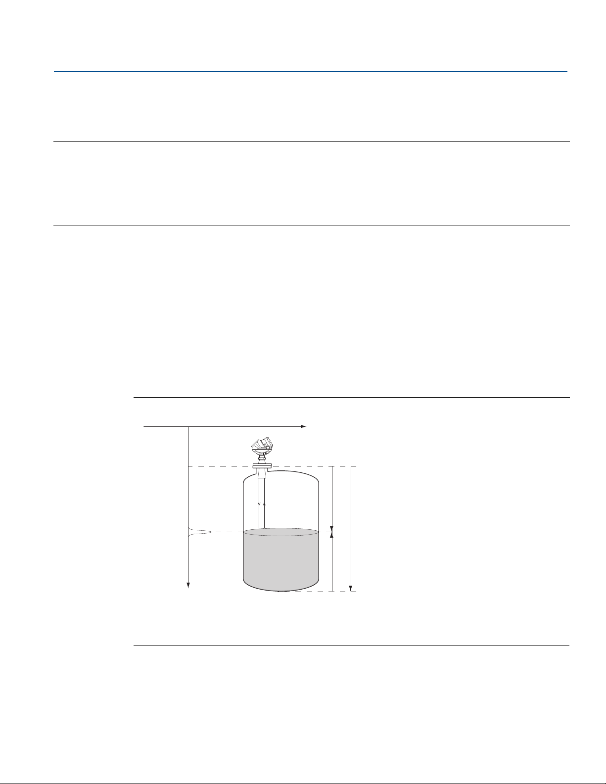
The Rosemount 5400 Level Transmitter is a smart, two-wire continuous level transmitter. A Rosemount
5400 is installed at the top of the tank and emits short microwave pulses towards the product surface in
the tank. When a pulse reaches the surface, part of the energy is reflected back to the antenna for
subsequent processing by the transmitter electronics. The time difference between the transmitted and
reflected pulse is detected by a micro-processor and is converted into a distance, which calculates the
level.
Transmitter Overview
June 2016
The product level is related to the tank height and the measured distance by the following expression:
Level = Tank Height - Distance
Figure 2-1. Measurement Principle for the Rosemount 5400
A. Signal amplitude D. Distance
B. Radar pulse E. Level
C. Time F. Tank height
Tra nsm itter Overvi ew
3
Page 18
Transmitter Overview
June 2016
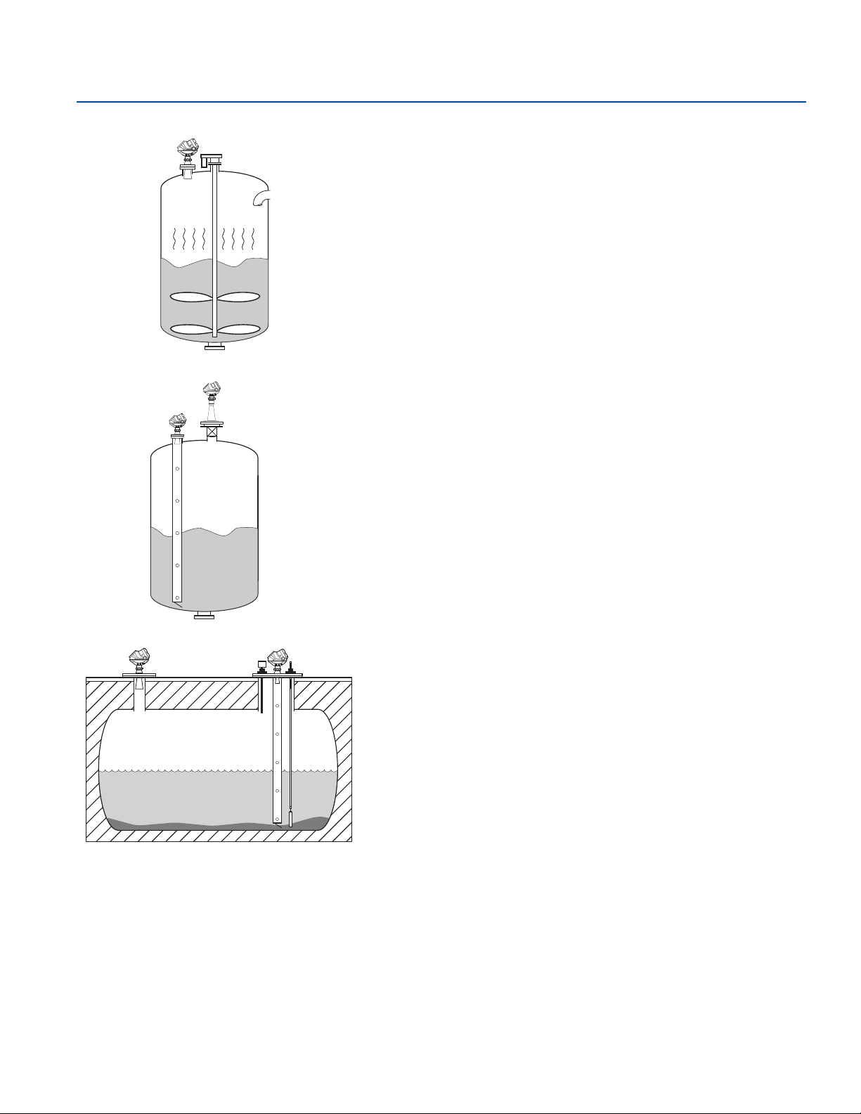
2.2 Application examples
Tanks, vessels, and containers with calm surfaces
Non-contacting radar can be used in less challenging applications, such as storage
and buffer tanks:
It is easy to mount, maintenance-free, and highly accurate
Gives precise monitoring and control of the process
Overfill and underfill detection
The Rosemount 5400 can be advantageous in risk reduction systems:
Continuous measurement may reduce or simplify proof-tests
Multiple Rosemount 5400s can be used in the same tank
Reference Manual
00809-0100-4026, Rev KB
Corrosives
Radar measurement is ideal for most corrosive products, such as caustics, acids,
solvents, and many other chemicals:
Does not contact the process product
Wide material offering such as PTFE, Alloy C-276 and Alloy 400
Works well in non-metallic tanks also
Sticky, viscous, and crystallizing products
The best-in-class Rosemount 5400 provides an accurate and reliable level reading
with difficult products, such as resins and adhesives:
Non-contacting is best practice
Almost unaffected by coating and build-up because of the uniquely designed
condensation resistant antennas
Sludges and slurries
Applications like mud, pulp-stock, and lime slurries are ideal for non-contacting
measurement:
Immune to splashing and solids content
Unaffected by density changes
No re-calibration, no or little maintenance
4
Tra nsmit ter O vervi ew
Page 19
Reference Manual
00809-0100-4026, Rev KB
Transmitter Overview
June 2016
Reactor vessels
The innovative design of the Rosemount 5400 makes it an excellent choice for the
most difficult applications, such as reactor vessels:
Unique circular polarization provides greater mounting flexibility – no tank
wall clearance distance is needed
Direct measurement – independent of most variations in process conditions,
such as density, dielectric, vapor, temperature, and pressure
Can handle turbulent conditions created by agitation, top-filling, or process
reaction
Mounting flexibility
The versatile Rosemount 5400 can be used in mounting configurations other than
standard nozzles:
Fits most existing pipes: 2- to 8-in. (50-200 mm)
Easy to isolate from the process – use a ball-valve
Still-pipes reduce the influence of foam, turbulence, and tank obstructions.
Ball-valves can be used on both still-pipes and nozzles.
Tra nsm itter Overvi ew
Underground tanks
The mounting flexibility of the Rosemount 5400 makes it an excellent choice for
many underground tanks:
Easy top-mounting
Can handle long narrow nozzles up to 6 ft (2 m) as long as they are clean and
smooth, and pipes
Unaffected by dirty products with solids content
5
Page 20
Transmitter Overview
A
B
D
E
G
F
J
H
I
C
June 2016
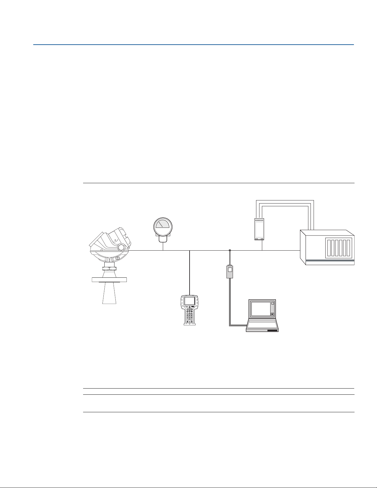
2.3 System architecture
Reference Manual
00809-0100-4026, Rev KB
The Rosemount 5400 is loop-powered, and uses the same two wires for power supply and output signal.
®
The output is a 4-20 mA analog signal superimposed with a digital HART
Modbus
®
signal.
, FOUNDATION™ Fieldbus or
By using the optional HART Tri-Loop™, the HART signal can be converted up to three additional 4-20 mA
analog signals.
With the HART protocol, multidrop configuration is possible. In this case, communication is restricted to
digital, since current is fixed to the 4 mA minimum value.
The transmitter can be connected to a Rosemount 751 Field Signal Indicator, or it can be equipped with
an integral display.
The transmitter can easily be configured using a Field Communicator or a PC with the Rosemount Radar
Master (RRM) software. Rosemount 5400 can also be configured with the AMS™ Suite and DeltaV™
software, and other tools that support Electronic Device Description Language (EDDL) functionality.
Figure 2-2. HART System Architecture
A. Integral display F. 3 x 4-20 mA
B. Rosemount 5400 G. Tri -L oo p
C. 4-20 mA/HART H. HART modem
D. Rosemount 751 Field Signal Indicator I. Rosemount Radar Master or AMS Suite
E. Field Communicator J. DCS
Note
For HART communication, a minimum load resistance of 250 within the loop is required.
6
Tra nsmit ter O vervi ew
Page 21
Reference Manual
FOUNDATION
Fieldbus
Note
Intrinsically safe
installations may
allow fewer devices
per I.S. barrier due to
current limitations.
B
F
A
C
D
E
J
I
6200 ft (1900 m) max
(depending upon cable
characteristics)
G
H
A
E
B
D
G
H
F
I
C
00809-0100-4026, Rev KB
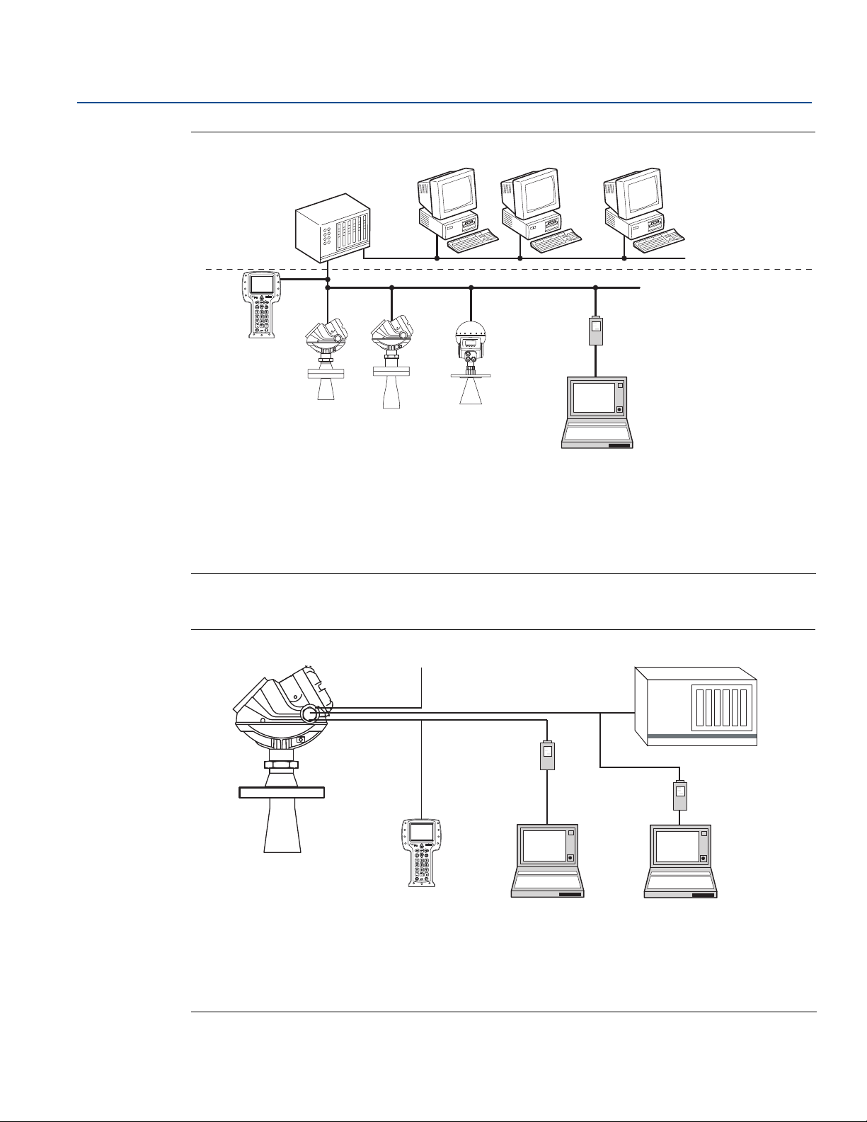
Figure 2-3. FOUNDATION Fieldbus System Architecture
Transmitter Overview
June 2016
A. 475 Field Communicator F. Maintenance
B. Host/DCS system (e.g. DeltaV) G. Configuration with RRM (hooked up on Fieldbus segment)
C. Rosemount 5401 H. H2 - High speed field bus
D. Rosemount 5402 I. H1 - Low speed field bus
E. Rosemount 5601 J. Fieldbus modem
The RS-485 Modbus version communicates by Modbus RTU, Modbus ASCII, and Level Master Protocols.
HART communication is used for configuration via HART terminals, or tunneling via the RS-485.
Figure 2-4. RS-485 with Modbus Communication
Tra nsm itter Overvi ew
A. Rosemount 5400 F. PC 5400 Setup in Rosemount Radar Master
B. Power G. Control System
C. Field Communicator H. RS-232/RS-485 Converter
D. Modbus, Levelmaster Emulation/RS-485 I. PC 5400 Setup in Rosemount Radar Master via Tunneling
E. HART modem
7
Page 22

Transmitter Overview
June 2016
2.4 Process characteristics
Dielectric constant
A key parameter for measurement performance is reflectivity. A high dielectric constant of the media
provides better reflection and enables a longer measuring range.
Foam
Rosemount 5400 Series Radar Transmitter measurement in foamy applications depends on the foam
properties; light and airy or dense and heavy, high or low dielectrics, etc. If the foam is conductive and
creamy, the transmitter may measure the surface of the foam. If the foam is less conductive, the
microwaves may penetrate the foam and measure the liquid surface.
Turb ul enc e
A calm surface gives better reflection than a turbulent surface. For turbulent applications, the maximum
range of the radar transmitters is reduced. The range depends on the frequency, the antenna size, the
dielectric of the material, and the degree of turbulence. Consult Table 2-2 on page 11 and Table 2-3 on
page 12 for the expected maximum range with the variables listed.
Reference Manual
00809-0100-4026, Rev KB
Temperature/pressure/density and vapor
Temperature, pressure, product density, and vapor generally have no impact on measurements.
Condensation
For applications where heavy condensation and vapors may occur, the low frequency version Rosemount
5401 is recommended.
Tank characteristics
The conditions inside the tank have a significant impact on measurement performance. For more
information see “Vessel characteristics” on page 34.
8
Tra nsmit ter O vervi ew
Page 23

Reference Manual
00809-0100-4026, Rev KB
Solid surface
The surface of solid materials is rarely flat or horizontal. The surface inclination will change as the vessel
fills and empties. There is often a lot of dust during the fill cycle. The dielectric value of many solids is
fairly low. See Table 2-1 on page 9 for common solids characteristics.
For solids applications, the high frequency version Rosemount 5402 with 4 inch cone or parabolic
antenna is available.
Table 2-1. Sample Solids Applications
Transmitter Overview
June 2016
(1)
Common characteristics
Particle size Vapor space
Dust or
Applications
Wood chip bins Yes Yes Yes Yes Possible
Grain silo - small
kernel grains
Grain silo - large kernel
grains
Lime stone silo No Yes Yes Possible No
Cement - raw mill silo Yes Yes No Yes No
Cement - finished
product silo
Coal bin Yes Yes Yes Yes Yes
Saw dust Yes Yes No Yes No
High consistency pulp stock
Alumina Yes Yes No Yes No
Salt No Yes Yes No No
powder
Yes Yes No Yes No
No Yes No No No
Yes Yes No Yes No
No No No No Yes
Small
(<1 in.)
Larger
(>1 in.)
Dust
Steam or
condensation
1. Air purging might be needed in dusty environments.
Tra nsm itter Overvi ew
9
Page 24
Transmitter Overview
B
G
H
A
E
F
D
C
June 2016
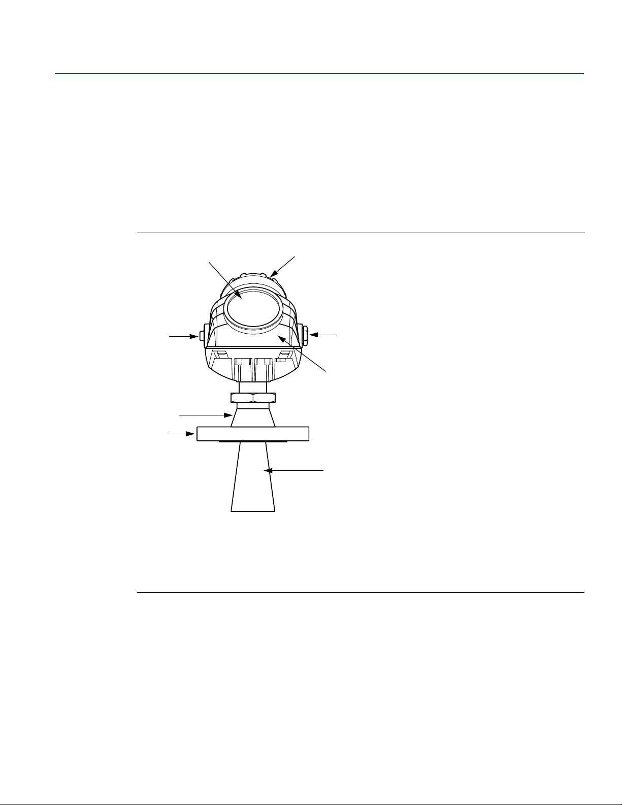
2.5 Components of the transmitter
The Rosemount 5400 is available with a die-cast aluminum or stainless steel (SST) housing containing
advanced electronics for signal processing.
The radar electronics produces an electromagnetic pulse that is emitted through the antenna. There are
different antenna types and sizes available for various applications.
The transmitter head has separate compartments for electronics and terminals, and can be removed
without opening the tank. The head has two entries for conduit/cable connections.
The tank connection consists of a Tank Seal and a flange (ANSI, EN (DIN) or JIS).
Figure 2-5. Transmitter Components
Reference Manual
00809-0100-4026, Rev KB
A. Display Panel E. Ter min al s ide
10
B. Cable Entry: ½" NPT
Optional adapters: M20
C. Ta nk Seal G. Transmitter head with Radar electronics
D. Flange H. Antenna
F. Cable Entry: ½" NPT.
Optional adapters: M20
Tra nsmit ter O vervi ew
Page 25
Reference Manual
Transmitter Overview
00809-0100-4026, Rev KB
2.6 Antenna selection guide/measuring range
The measuring range depends on the microwave frequency, antenna size, the dielectric constant (r) of
the liquid, and process conditions. A higher dielectric constant value produces a stronger reflection. The
figures in the tables below are guidelines for optimum performance. Larger measuring ranges may be
possible. For more information, contact your local Emerson
A. Oil, gasoline or other hydrocarbons, and petrochemicals (
surface conditions, for some liquefied gases (
B. Alcohols, concentrated acids, organic solvents, oil/water mixtures, and acetone
(
= 4.0-10.0).
r
C. Conductive liquids, e.g. water based solutions, dilute acids, and alkalis (
Table 2-2. Rosemount 5402, Maximum Recommended Measuring Range, ft (m)
High
frequency
antennas
Dielectric constant
™
Process Management representative.
= 1.4-4.0).
r
= 1.9-4.0). In pipes or with ideal
r
(1)
> 10.0).
r
June 2016
A B C A B C A B C
2-in. Cone/
Process seal
3-in. Cone/
Process seal
4-in. Cone/
Process seal
1. A. Oil, gasoline or other hydrocarbons, and petrochemicals (
(
= 1.4-4.0)
r
B. Alcohols, concentrated acids, organic solvents, oil/water mixtures, and acetone (
C. Conductive liquids, e.g. water based solutions, dilute acids, and alkalis (
33
(10)
49
(15)
66
(20)
49
(15)
66
(20)
82
(25)
66
(20)
98
(30)
115
(35)
82
(25)
82
(25)
82
(25)
= 1.9-4.0) In pipes or with ideal surface conditions, for some liquefied gases
r
115
(35)
115
(35)
115
(35)
> 10.0)
r
= 4.0-10.0)
r
115
(35)
115
(35)
115
(35)
9.8
(3)
13
(4)
23
(7)
20 (
6)
30
(9)
39
(12)
33
(10)
39
(12)
49
(15)
Tra nsm itter Overvi ew
11
Page 26
Transmitter Overview
June 2016
Table 2-3. Rosemount 5401, Maximum Recommended Measuring Range, ft (m)
Low
Frequency
Antennas
Reference Manual
00809-0100-4026, Rev KB
Dielectric Constant
A B C A B C A B C
(1)
N/A N/A N/A 82
(3)
= 1.4-4.0)
r
(2)
23
(7)
43
(13)
66
(20)
39
(12)
66
(20)
82
(25)
49
(15)
82
(25)
115
(35)
(25)
82
(25)
82
(25)
82
(25)
3-in. Cone
4-in. Cone /
Rod
6-in. Cone
8-in. Cone
1. A. Oil, gasoline or other hydrocarbons, and petrochemicals (r = 1.9-4.0) In pipes or with ideal surface conditions, for some liquefied gases
(
B. Alcohols, concentrated acids, organic solvents, oil/water mixtures, and acetone (
C. Conductive liquids, e.g. water based solutions, dilute acids, and alkalis (
2. Pipe installations only. NA = Not Applicable.
3. Pipe installations are not allowed with rod antennas.
115
(35)
115
(35)
115
(35)
115
(35)
> 10.0)
r
= 4.0-10.0)
r
115
(35)
115
(35)
115
(35)
115
(35)
N/A N/A N/A
13
(4)
20
(6)
26
(8)
26
(8)
33
(10)
39
(12)
39
(12)
46
(14)
52
(16)
12
Tra nsmit ter O vervi ew
Page 27
Reference Manual
Transmitter Overview
00809-0100-4026, Rev KB
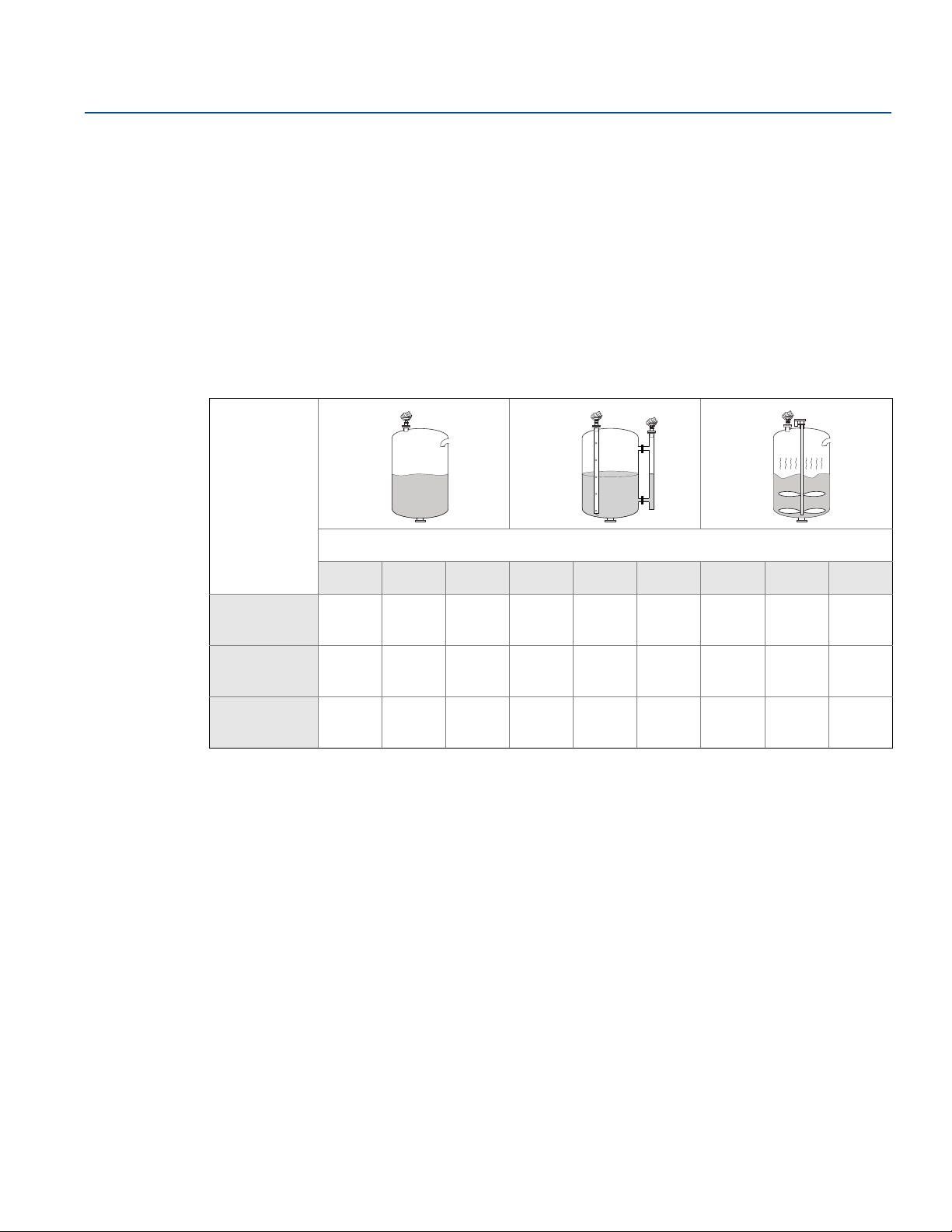
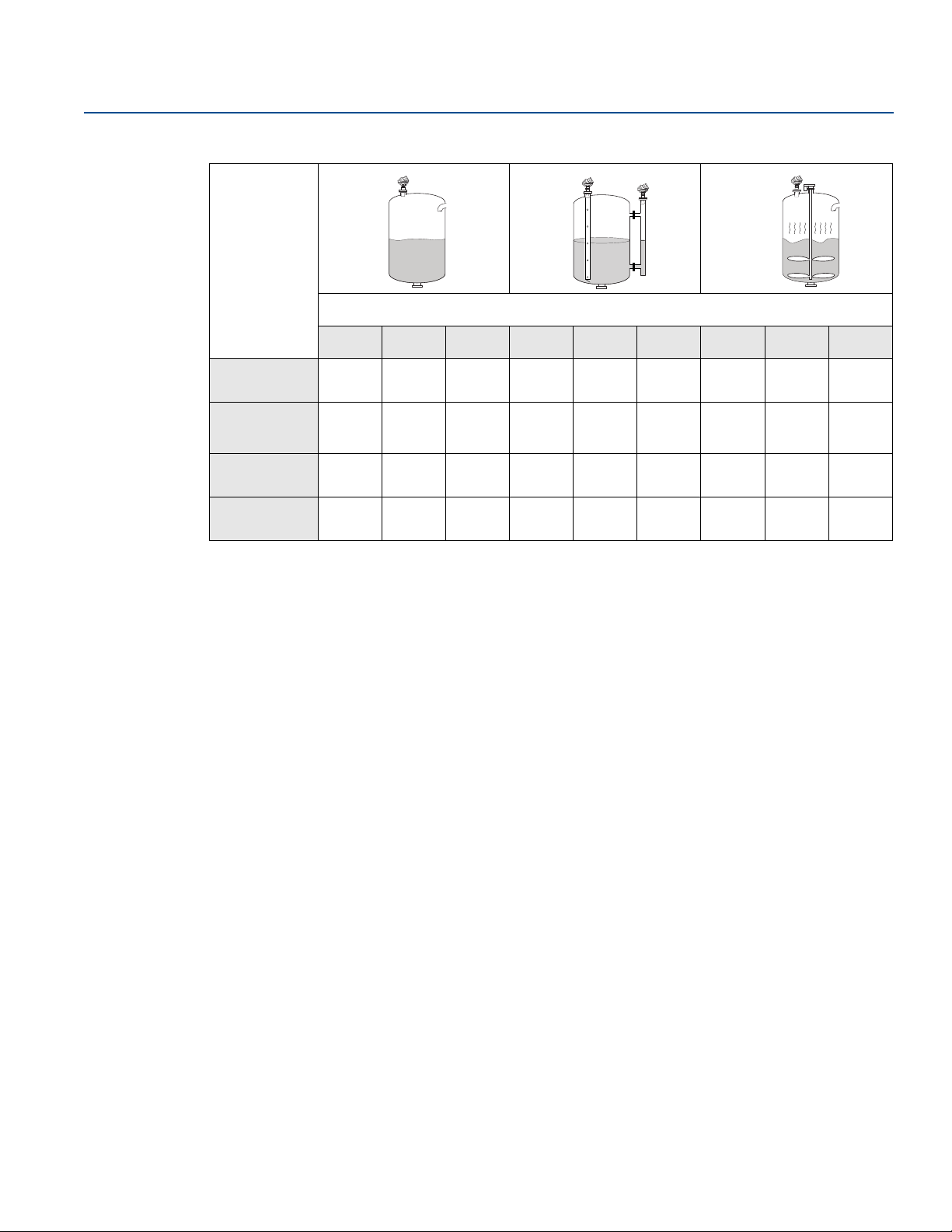
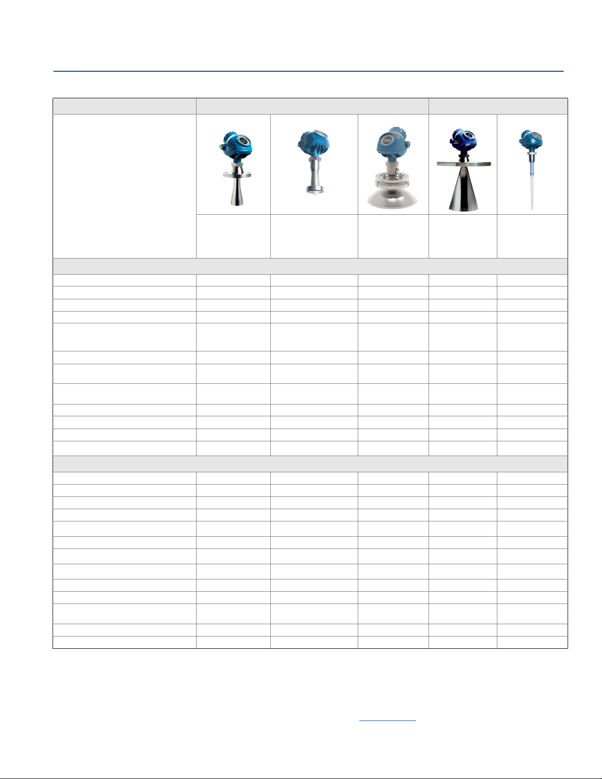
Table 2-4. Model and Antenna Guide
Model and antenna guide
Cone (preferred) Process seal Parabolic Cone (preferred) Rod
This table gives guidelines on which
model and antenna to select, depending
on application.
G = Good
AD = Application Dependent (consult
your local Emerson Process
Management representative)
NR = Not Recommended
Best choice for a
broad range of
applications, free
propagation and
pipe installations.
Tank considerations
Installation close to smooth tank wall G G AD G G
Multiple units on the same tank G G G G G
Internal obstructions, directly in path
Internal obstructions, avoidance
(1)
NR NR NR AD AD
(1)
G G AD NR NR
2” 19°
Beam angle
3” 14°
4” 9°
Antenna extends below nozzle G G G G G
Antenna recessed in smooth nozzle up
to 6 ft (2 m)
Antenna recessed in nozzle with
irregularities, such as bad welds
GG
(4)
AD
Stilling well mounting G (2- to 4-in. pipe) G (2- to 4-in. pipe) NR G (3- to 8-in. pipe) NR
Valves G G NR NR NR
Long ranges (>115’ / 35 m) NR NR NR NR NR
Cleanability of antenna AD G G
Process medium characteristics
Vapor (light, medium) G G G G G
Vapor (heavy) NR AD AD G G
Condensing vapor/product build-up
Boiling/Turbulent surface (low/medium) G G G G G
Boiling/Turbulent surface (heavy) AD AD G G
Boiling/Turbulent surface (still-pipe) G G NR G NR
(8)
Foam
Foam (still-pipe)
(8)
Corrosive products (options available) G
Materials with very low dielectric G G G G AD
Changing density/dielectric/pH/
pressure/temperature
Coating/viscous/crystallizing liquids G G G
Solids, granules, powders G NR G NR NR
1. The obstruction should not be within the radar beam. Preferred choices due to more narrow radar beam: Rosemount 5402, and cone antenna.
2. If tall nozzle, use extended antenna.
3. The active part must protrude beneath the nozzle.
4. An extended cone antenna must be used.
5. Air purging might be needed.
6. Build-up can often be avoided or reduced by using heat-tracing or cleaning arrangements.
7. Use a 6 or 8 in. (150-200 mm) cone antenna.
8. Foam can either reflect, be invisible, or absorb the radar signal. Pipe mounting is advantageous since it reduces the foaming tendency.
9. Other wetted material options include Alloy C-276 and Alloy 400. See the Rosemount 5400 Series Product Data Sheet for details.
(6)
AD G G
NR NR N/A AD AD
GG NRGNR
(9)
GG GGG
Rosemount 5402 Rosemount 5401
Ideal for small tanks
and corrosive
applications. Good for
heavy antenna
condensation/build-up.
2” 19°
3” 14°
4” 9°
AD AD AD
(9)
G
Only for solids
applications. Good
for long ranges.
Suitable for some
extreme process
conditions.
4” 37°
4.5°
6” 23°
8” 17°
NR NR
(5)
(5)
AD G
GAD
NR G
(5)
GG
(2)
(4)
(7)
(9)
June 2016
Suitable for small
process
connections, and
corrosive
environment.
37°
(3)
NR
(3)
NR
NR
G
Tra nsm itter Overvi ew
13
Page 28

Transmitter Overview
June 2016
Reference Manual
00809-0100-4026, Rev KB
14
Tra nsmit ter O vervi ew
Page 29

Reference Manual
00809-0100-4026, Rev KB
Section 3 Mechanical Installation
Safety messages . . . . . . . . . . . . . . . . . . . . . . . . . . . . . . . . . . . . . . . . . . . . . . . . . . . . . . . . . . . . . . . . . . page 15
Installation procedure . . . . . . . . . . . . . . . . . . . . . . . . . . . . . . . . . . . . . . . . . . . . . . . . . . . . . . . . . . . . . page 17
Mounting considerations . . . . . . . . . . . . . . . . . . . . . . . . . . . . . . . . . . . . . . . . . . . . . . . . . . . . . . . . . . page 18
Mounting . . . . . . . . . . . . . . . . . . . . . . . . . . . . . . . . . . . . . . . . . . . . . . . . . . . . . . . . . . . . . . . . . . . . . . . . page 35
3.1 Safety messages
Procedures and instructions in this section may require special precautions to ensure the safety of the
personnel performing the operations. Information that raises potential safety issues is indicated by a
warning symbol ( ). Refer to the following safety messages before performing an operation preceded
by this symbol.
Mechanical Installation
June 2016
Mechanical Installation
15
Page 30

Mechanical Installation
June 2016
Failure to follow safe installation and service guidelines could result in death or serious injury.
Make sure only qualified personnel perform the installation.
Use the equipment only as specified in this manual. Failure to do so may impair the protection
provided by the equipment.
Do not perform any services other than those contained in this manual unless you are qualified.
Process leaks could result in death or serious injury.
Make sure the transmitter is handled carefully. If the process seal is damaged, gas might escape from
the tank if the transmitter head is removed from the antenna.
Explosions could result in death or serious injury.
Verify that the operating environment of the transmitter is consistent with the appropriate
hazardous locations specifications.
In an Explosion-proof/Flameproof installation, do not remove the transmitter cover when power is
applied to the unit.
Before connecting a Field Communicator in an explosive atmosphere, make sure the instruments in
the loop are installed in accordance with intrinsically safe or non-incendive field wiring practices.
Do not remove the gauge cover in explosive atmospheres when the circuit is alive.
To prevent ignition of flammable or combustible atmospheres, disconnect power before servicing.
To avoid process leaks, only use O-rings designed to seal with the corresponding flange adapter.
Electrical shock can result in death or serious injury.
Avoid contact with the leads and terminals. High voltage that may be present on leads can cause
electrical shock.
Make sure the main power to the Rosemount
external power source are disconnected or not powered while wiring the transmitter.
Antennas with non-conducting surfaces.
Antennas with non-conducting surfaces (e.g. rod antenna and process seal antenna) may generate
an ignition-capable level of electrostatic charge under extreme conditions. Therefore, when the
antenna is used in a potentially explosive atmosphere, appropriate measures must be taken to
prevent electrostatic discharge.
Reference Manual
00809-0100-4026, Rev KB
™
5400 Level Transmitter is off and the lines to any other
16
Any substitution of non-authorized parts or repair, other than exchanging the complete
transmitter head or probe assembly, may jeopardize safety and is prohibited.
Unauthorized changes to the product are strictly prohibited as they may unintentionally and
unpredictably alter performance and jeopardize safety. Unauthorized changes that interfere with the
integrity of the welds or flanges, such as making additional perforations, compromise product
integrity and safety. Equipment ratings and certifications are no longer valid on any products that
have been damaged or modified without the prior written permission of Emerson™ Process
Management. Any continued use of product that has been damaged or modified without prior
written authorization is at the customer's sole risk and expense.
Mechanical Installation
Page 31

Reference Manual
Review installation
considerations
(see page 18)
Mount the transmitter
(see page 35)
Wire the transmitter
(see page 71)
Make sure covers and
cable/conduit
connections are tight
Power up the
transmitter
Configure the
transmitter
(see page 99)
Verify measurements
Ground the housing (see
page 73)
00809-0100-4026, Rev KB
3.2 Installation procedure
Follow these steps for proper installation:
Mechanical Installation
June 2016
Mechanical Installation
17
Page 32

Mechanical Installation
(D) (A) (E) (B) (F) (C)
June 2016
3.3 Mounting considerations
Before installing a Rosemount 5400, consider specific mounting requirements, vessel, and process characteristics.
3.3.1 Mounting location
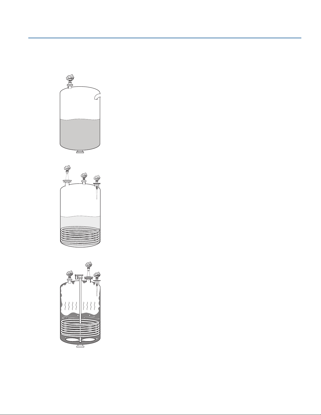
For optimal performance, the transmitter should be installed in locations with a clear and unobstructed
view of the level surface (A):
Filling inlets creating turbulence (B), and stationary metallic objects with horizontal surfaces (C)
should be kept outside the signal beam – see page 32 for beam width information
Agitators with large horizontal blades may reduce the performance of the transmitter, so install the
transmitter in a location where this effect is minimized. Vertical or slanted blades are often invisible to
radar, but create turbulence (D)
Do not install the transmitter in the center of the tank (E)
Because of circular polarization, there is no clearance distance requirement from the tank wall if it is
flat and free of obstructions such as heating coils and ladders (F). Usually, the optimal location is
the diameter from the tank wall
Reference Manual
00809-0100-4026, Rev KB
1
/4 of
Figure 3-1. Proper Mounting Position
The antenna is normally aligned vertically.
18
Mechanical Installation
Page 33

Reference Manual
(G)
(H)
00809-0100-4026, Rev KB
A metal still-pipe can be used to avoid disturbing objects, turbulence, and foam (G).
Figure 3-2. Mounting in Still-Pipe
Mechanical Installation
June 2016
The walls in non-metallic tanks are invisible to the radar signal, so nearby objects outside of the tank
may be detected.
Choose the largest possible antenna diameter for installation. A larger antenna concentrates the radar
beam, will be less susceptible to obstruction interference, and assures maximum antenna gain.
Multiple Rosemount 5400 can be used in the same tank without interfering with each other (H).
Figure 3-3. Multiple Rosemount 5400 in the Same Tank
Mechanical Installation
19
Page 34

Mechanical Installation
June 2016
3.3.2 Special considerations in solids applications
Reference Manual
00809-0100-4026, Rev KB
The transmitter should be mounted as close to the center of the tank as possible, but not in the center
of the tank. A general practice is to mount the transmitter at
2
/3 tank radius from the tank wall, see
Figure 3-4.
Figure 3-4. Transmitter Location in Solids Applications
The radar signal must never be shaded by the inlet nor the injected product, see Figure 3-5.
Figure 3-5. Install the Transmitter with a Clear and Unobstructed View
20
Mechanical Installation
Page 35

Reference Manual
Max. 0.2 in
(5 mm)
max. 1 °
00809-0100-4026, Rev KB
3.3.3 Mounting in pipes
Still-pipe mounting is recommended for tanks with extremely turbulent surface conditions. All cone
antenna sizes for the Rosemount 5400 can be used for still-pipe installations. The 3-in. (75 mm) antenna
for the Rosemount 5401 is designed for use in still-pipes only. Parabolic and rod antennas are not
recommended for still-pipes.
Mechanical Installation
June 2016
When the transmitter is mounted on a still-pipe, the inclination should be
within 1°. The gap between the antenna and the still-pipe may be up to 0.2 in. (5 mm).
Figure 3-6. Mount the Transmitter Vertically
Recommendations for pipe installations
Mechanical Installation
The pipe interior must be smooth.
Not suitable for adhesive products.
At least one hole is above the product surface.
The hole diameter Ø should not exceed 10 % of the pipe diameter D (see Figure 3-7 on page 22).
Holes should only be drilled on one side.
21
Page 36

Mechanical Installation
min. 6 in. (150 mm)
max. Ø: D/10.
D
June 2016
Figure 3-7. Recommended Hole Size for Pipe Installations
3.3.4 Condensation conditions
Reference Manual
00809-0100-4026, Rev KB
Generally, the radar signal is unaffected by condensation and low pressure steam. If affected, the lower
microwave frequencies are less affected. The critical point is the tank penetration, which acts as a cold
spot, where the condensation will form. The radar antenna is located at this cold spot.
If droplets of water build up on the antenna parts, the microwave signal may get partially or even entirely
blocked if the antenna is not designed for easy drip-off. Therefore, here it is beneficial to use as large
opening for the microwaves as possible, which is the main reason for the oversized PTFE seal in the
Rosemount 5400. An even better solution is to use a Process Seal Antenna if the process pressure permits
that.
To reduce the cold spot within the nozzle, it is always recommended to insulate the nozzle. By doing so,
the temperature in the nozzle will be the same as in the rest of the vessel and condensation will thus be
reduced. If the temperature in the tank is much higher than the ambient temperature (i.e. tank is heated
and located in a cold area), it might be necessary to heat trace the nozzle in addition to the insulation.
Figure 3-8. Insulate Nozzle to Avoid Condensation
22
Mechanical Installation
Page 37

Reference Manual
Spray nozzle
(I)
Smooth nozzle
Bad weldings
(K) Bad welding
(J)
00809-0100-4026, Rev KB
3.3.5 Nozzle considerations
Special considerations may have to be taken because of the nozzle, depending on the selection of
transmitter model and antenna.
Rosemount 5402 with cone antenna
The antenna can be recessed in smooth nozzles up to 6 ft (2 m). If the inside of the nozzle contains
disturbing objects, use the extended cone (I).
Figure 3-9. Nozzle Considerations for Rosemount 5402 with Cone Antenna
Mechanical Installation
June 2016
Rosemount 5402 with process seal antenna
The antenna can be used on nozzles up to 6 ft (2 m), (J). Disturbing objects inside the nozzle (K) may
impact the measurement, and should therefore be avoided.
The flange on the tank should have a flat or raised face. Other tank flanges may be possible, please
consult your local Emerson Process Management representative for advice.
Figure 3-10. Nozzle Considerations for Rosemount 5402 with Process Seal Antenna
Mechanical Installation
23
Page 38

Mechanical Installation
(M) Bad welding
(L)
(N) 0.4 in. (10 mm) or more
June 2016
Rosemount 5402 with parabolic antenna
The antenna can be recessed in smooth nozzles up to (L):
6 in. (150 mm) for 8-in. pipe sch std
8 in. (200 mm) for 10-in. pipe sch std
Disturbing objects inside the nozzle (M) may impact the measurement, and should be avoided.
Figure 3-11. Nozzle Considerations for Rosemount 5402 with Parabolic Antenna
(1)(2)
(2)
Reference Manual
00809-0100-4026, Rev KB
.
.
Rosemount 5401 with cone antenna
The antenna should extend 0.4 in. (10 mm), or more, below the nozzle (N). If required, use the extended
cone solution.
Figure 3-12. Nozzle Considerations for Rosemount 5401 with Cone Antenna
1, Only applicable for perpendicular installations or (L) less than 2 in. (50 mm).
2, See Table 3-4 on page 29 for information on angled parabolic antenna installation in nozzle.
24
Mechanical Installation
Page 39

Reference Manual
Active part
starts here
(O)
Max. 4 or 10 in.
(100 or 250 mm)
for short and
long version
respectively
(P)
Max. 0.2 in.
(5 mm)
00809-0100-4026, Rev KB
Rosemount 5401 with rod antenna
The active part of the rod antenna should protrude below the nozzle (O).
Figure 3-13. Nozzle Considerations for Rosemount 5401 with Rod Antenna
Still-pipes in metallic materials
Mechanical Installation
June 2016
If used correctly, pipe measurement can be advantageous in many applications:
The Rosemount 5402 is the preferred choice for smaller pipe diameters.
Use the Rosemount 5401 for larger pipe diameters (6-8 in./150-200 mm),
pipes with larger holes or slots, or for dirty/sticky media.
Use cone or process seal antennas - not the rod antenna or the parabolic antenna.
The gap between the cone antenna and the still-pipe is limited to 0.2 in. (5 mm). If required, order an
oversized antenna and cut on location (P). Only applicable to Rosemount 5401 cone antennas and
cone antennas with wetted flange plate (i.e. straight antennas).
The inside of the chamber must be of a constant diameter.
Note
Match antenna size to the stilling well diameter.
Figure 3-14. Nozzle Considerations for Still-Pipes in Metallic Materials
Mechanical Installation
25
Page 40

Mechanical Installation
June 2016
Ball-valve installation
The Rosemount 5400 can be isolated from the process by using a valve:
The Rosemount 5402 is the preferred choice for long nozzle measurement.
Use the largest possible antenna.
Use a full-port ball valve.
Ensure there is no edge between the ball valve and the nozzle or stilling well, the inside should be
smooth.
Valves can be combined with stilling wells.
Reference Manual
00809-0100-4026, Rev KB
26
Mechanical Installation
Page 41

Reference Manual
Minimum diameter
> 0.4 in.
(10 mm)
L
00809-0100-4026, Rev KB
3.3.6 Nozzle recommendations and requirements
The Rosemount 5400 is mounted on a nozzle by using appropriate flanges. For best performance, it is
recommended that the nozzle meets the following recommendations for height (L) and diameter:
Figure 3-15. Mounting of the Rosemount 5400 Cone Antenna
Table 3-1. Minimum Nozzle Diameter and Recommended Maximum Nozzle Height for Cone
Antennas
Mechanical Installation
June 2016
L
max
Model Antenna/material
(1)
5402
5401
1. For Rosemount 5402, the values for maximum nozzle height are recommendations. Note that the Rosemount 5402 with cone antenna can
be recessed in smooth nozzles up to 6 ft (2m).
Cone 2 in. (50 mm) SST 6.1 (155) 2.2 (55)
Cone 3 in. (75 mm) SST 5.5 (140) 2.8 (72)
Cone 4 in. (100 mm) SST 8.5 (215) 3.8 (97)
Cone 2 in. (50 mm) Alloy C-276, Alloy 400 5.5 (140) 2.2 (55)
Cone 3 in. (75 mm) Alloy C-276, Alloy 400 6.5 (165) 2.8 (72)
Cone 4 in. (100 mm) Alloy C-276, Alloy 400 9.6 (240) 3.8 (97)
Cone 3 in. (75 mm) SST Pipe installations only
Cone 4 in. (100 mm) SST 5.5 (140) 3.8 (97)
Cone 6 in. (150 mm) SST 6.9 (175) 5.7 (145)
Cone 8 in. (200 mm) SST 10.2 (260) 7.6 (193)
Cone 3 in. (75 mm) Alloy C-276, Alloy 400 Pipe installations only
Cone 4 in. (100 mm) Alloy C-276, Alloy 400 5.5 (140) 3.8 (97)
Cone 6 in. (150 mm) Alloy C-276, Alloy 400 6.9 (175) 5.7 (145)
Cone 8 in. (200 mm) Alloy C-276, Alloy 400 10.2 (260) 7.6 (193)
in. (mm)
Min. diameter
in. (mm)
Mechanical Installation
27
Page 42

Mechanical Installation
Minimum diameter
L
Minimum diameter
L
June 2016
Figure 3-16. Mounting of the Rosemount 5400 Rod Antenna
Table 3-2. Minimum Nozzle Diameter and Maximum Nozzle Height for Rod Antennas
Reference Manual
00809-0100-4026, Rev KB
Model Antenna L
(1)
5401
Rod (short) 4.0 (100) 1.5 (38)
in. (mm) Min. diameter in. (mm)
max
Rod (long) 10 (250) 1.5 (38)
1. For Rosemount 5401, the values for minimum nozzle diameter and maximum nozzle height are requirements.
Figure 3-17. Mounting of the Rosemount 5400 Process Seal Antenna
Table 3-3. Minimum Nozzle Diameter and Recommended Maximum Nozzle Height for Process
Seal Antennas
28
Model Antenna L
(1)
5402
Process Seal 2 in. (50 mm) 19.7 (500) 2.0 (51)
in. (mm) Min. diameter in. (mm)
max
Process Seal 3 in. (75 mm) 19.7 (500) 3.0 (77)
Process Seal 4 in. (100 mm) 19.7 (500) 4.0 (102)
1. For Rosemount 5402, the values for maximum nozzle height are recommendations. Note that the Rosemount 5402 with process seal
antenna can be recessed in smooth nozzles up to 6 ft (2m).
Mechanical Installation
Page 43

Reference Manual
Inclination angle
L
Inclination angle
L
Ø 8 in. (200 mm)
Ø
Nozzle mounting
Flange mounting in manhole cover
00809-0100-4026, Rev KB
Figure 3-18. Mounting of the Rosemount 5400 Parabolic Antenna
Mechanical Installation
June 2016
Table 3-4. Recommended Maximum Nozzle Height for Parabolic Antennas at Different Inclination
Model Nozzle size Inclination angle L
(1)
5402
1. For Rosemount 5402, the values for maximum nozzle height are recommendations.
Angle
Pipe sch std, Ø 8 in. (200 mm)
Pipe sch std, Ø10 in. (250 mm)
in. (mm)
max
0° 5.9 (150)
3° 5.5 (140)
6° 1.6 (40)
9° 1.2 (30)
12° 1.0 (25)
15° 0.6 (15)
0° 8.0 (200)
3° 8.0 (200)
6° 8.0 (200)
9° 8.0 (200)
12° 5.9 (150)
15° 4.3 (110)
Mechanical Installation
29
Page 44

Mechanical Installation
L
Minimum diameter
> 0.4 in.
(10 mm)
June 2016
Figure 3-19. Mounting of the Rosemount 5400 Extended Cone Antenna
Table 3-5. Minimum Nozzle Diameter and Maximum Nozzle Height for Extended Cone Antennas
Reference Manual
00809-0100-4026, Rev KB
Model Antenna L
(1)
5402
5401
1. For Rosemount 5402, the values for maximum nozzle height are recommendations.
2. The extended cone antennas are available in 5 in. (125 mm) step increments from 10 to 50 in. (250-1250 mm). Consult your local
Emerson Process Management representative for more information. Expect long lead times for sizes other than the 20 in. (500 mm)
version.
Extended Cone Antenna, S3
Extended Cone Antenna, S3
(2)
(2)
in. (mm) Min. diameter in. (mm)
max
20 (500) See Ta bl e 3 - 1
20 (500) See Ta bl e 3 - 1
Install the transmitter as follows:
Align the antenna vertically.
Choose the largest antenna diameter possible. A larger receiving area concentrates the radar beam
and ensures maximum antenna gain. Increased antenna gain permits greater margin for weak surface
echoes. A larger antenna also results in smaller beam angle and thereby, less interference from any
internal structures in the tank.
For best measurement performance, the antenna should extend below the nozzle
0.4 in. (10 mm) or more.
For more information, see “Nozzle considerations” on page 23.
30
Mechanical Installation
Page 45

Reference Manual
A
B
C
Rod antenna
Cone antenna
A
B
C
C
B
A
Process seal
antenna
Parabolic
antenna
A
B
C
00809-0100-4026, Rev KB
3.3.7 Service space
For easy access to the transmitter, mount it with sufficient service space.
Mechanical Installation
June 2016
There is no requirement on clearance distance from the tank wall, provided it is flat and free of
obstructions such as heating coils and ladders. The optimal location is often
for solids installations
2
/3 tank radius from the tank wall.
1
/4 of the tank diameter, and
Figure 3-20. Service Space Recommendations
Service space Antenna type Distance in. (mm)
A Cone, rod, process seal, parabolic 20 (500)
B Cone, rod 24 (600)
Inclination Antenna type Maximum angle
C Cone, rod, process seal 3°
Process seal 33 (850)
Parabolic 26 (650)
Parabolic 15°
Mechanical Installation
31
Page 46

Mechanical Installation
Distance
Rosemount 5401
(low frequency)
Rosemount 5402
(high frequency)
16 ft (5 m)
33 ft (10 m)
49 ft (15 m)
66 ft (20 m)
Beamwidth
June 2016
3.3.8 Beam width
The following recommendations should be considered when mounting the transmitter:
The transmitter should be mounted with as few internal structures as possible within the beam angle.
The flat tank wall can be located within the antenna beam angle if there is a minimum distance from
the transmitter to the tank wall (see Figure 3-20 for preferred installation).
Figure 3-21. Beam Width at Various Distances from the Flange
Reference Manual
00809-0100-4026, Rev KB
Table 3-6. Beam Width for the Rosemount 5402 Model (in ft [m])
Antenna
Distance
16 ft (5 m)
33 ft (10 m)
49 ft (15 m)
66 ft (20 m)
2 in. (DN 50)
cone/
process seal
4.9 (1.5) 3.3 (1.0) 3.3 (1.0) 1.3 (0.4)
9.8 (3.0) 6.6 (2.0) 4.9 (1.5) 2.6 (0.8)
14.8 (4.5) 9.8 (3.0) 8.2 (2.5) 3.9 (1.2)
19.7 (6.0) 13.1 (4.0) 9.8 (3.0) 5.2 (1.6)
3 in. (DN 80)
cone/
process seal
4 in. (DN 100)
cone/
process seal
Parabolic
32
Mechanical Installation
Page 47

Reference Manual
Beam angle
00809-0100-4026, Rev KB
Table 3-7. Beam Width for the Rosemount 5401 Model (in ft [m])
Mechanical Installation
June 2016
Antenna
4 in. (DN 100)
Distance
16 ft (5 m)
33 ft (10 m)
49 ft (15 m)
66 ft (20 m)
cone /rod
9.8 (3..0) 6.6 (2.0) 4.9 (1.5)
21.3 (6.5) 13.1 (4.0) 9.8 (3.0)
32.8 (10) 19.7 (6.0) 14.8 (4.5)
41 (12.5) 26.2 (8.0) 19.7 (6.0)
Figure 3-22. Beam Angle
6 in. (DN 150)
cone
8 in. (DN 200)
cone
Mechanical Installation
Table 3-8. Beam Angle for the Rosemount 5402
Antenna Beam angle
2 in. (50 mm) cone / process seal 19°
3 in. (75 mm) cone / process seal 14°
4 in. (100 mm) cone / process seal, rod 9°
Parabolic 4.5°
Table 3-9. Beam Angle for the Rosemount 5401
Antenna Beam angle
3 in. (75 mm) cone Pipe installations only
4 in. (100 mm) cone / rod 37°
6 in. (150 mm) cone 23°
8 in. (200 mm) cone 17°
33
Page 48

Mechanical Installation
June 2016
3.3.9 Vessel characteristics
Heating coils, agitators and other objects in the tank may lead to disturbing echoes and noise in the
measurement signal. Vertical structures cause minimal effect since the radar signal is scattered rather
than directed back to the antenna.
The shape of the tank bottom affects the measurement signal when the product surface is close to the
tank bottom. The Rosemount 5400 has built-in functions which optimize measurement performance for
various bottom shapes (see “Tank type and tank bottom type” on page 103).
3.3.10 Disturbing objects
The Rosemount 5400 should be mounted so that objects such as heating coils, ladders, etc. are not in
the radar signal path. These objects may cause false echoes resulting in reduced measurement
performance. However, the transmitter has built-in functions designed to reduce the influence from
disturbing objects where such objects cannot be totally avoided.
The Rosemount 5402 has a narrower radar beam that is particularly suitable in installations with tall or
narrow nozzles, or nozzles close to the tank wall. It may also be used to avoid disturbing objects in the
tank.
Reference Manual
00809-0100-4026, Rev KB
3.3.11 Valves
The Rosemount 5400 can be isolated from the process by using a valve:
Use a full-port ball valve.
The Rosemount 5402 is the required and the process seal antenna is the preferred choice, since it does
not require a spool piece. The cone antenna can also be used.
Ensure there is no edge between the ball valve and the nozzle/pipe, the inside should be smooth.
Valves can be combined with stilling wells.
34
Mechanical Installation
Page 49

Reference Manual
Gasket
Tor qu e
30 Lbft (40 Nm)
00809-0100-4026, Rev KB
3.4 Mounting
Mount the transmitter on a nozzle on top of the tank making sure only qualified personnel perform the
installation.
The transmitter housing must not be opened.
If the transmitter housing must be removed for service, make sure the PTFE sealing is carefully protected
against dust and water.
3.4.1 Cone antenna with flange connection
1. Lower transmitter with antenna and flange into the nozzle. Tighten bolts and nuts with sufficient
torque for the flange and gasket choice.
Mechanical Installation
June 2016
Mechanical Installation
2. Adjust display orientation (optional).
35
Page 50

Mechanical Installation
Use anti-seize paste or PTFE tape
according to your site procedures.
June 2016
3.4.2 Cone antenna with threaded tank connection
1. Seal and protect threads.
2. Lower the device into the tank.
Reference Manual
00809-0100-4026, Rev KB
36
3. Screw the adapter into the process connection.
Mechanical Installation
Page 51

Reference Manual
Tor que 3 0 L bft
(40 Nm)
00809-0100-4026, Rev KB
4. Rotate the transmitter head so the cable entries/display face the desired direction.
Mechanical Installation
June 2016
Mechanical Installation
37
Page 52

Mechanical Installation
d
D
Gasket
June 2016
Reference Manual
00809-0100-4026, Rev KB
3.4.3 Cone antenna with threaded tank connection and customer
supplied flange
Antenna diameter (D) ≤ Flange hole diameter (d)
1. Place a gasket on the tank flange.
2. Place the customer supplied flange over the gasket.
3. Tighten the bolts and nuts with sufficient torque for the flange and gasket choice.
38
Mechanical Installation
Page 53

Reference Manual
Use anti-seize paste or PTFE tape
according to your site procedures.
00809-0100-4026, Rev KB
4. Seal and protect threads.
5. Lower the device into the tank.
Mechanical Installation
June 2016
Mechanical Installation
6. Screw the adapter into the process connection.
39
Page 54

Mechanical Installation
Torque 30 Lbft
(40 Nm)
d
D
June 2016
7. Rotate the transmitter head so the cable entries/display face the desired direction.
Reference Manual
00809-0100-4026, Rev KB
Antenna diameter (D) > Flange hole diameter (d)
1. Place the device on a workbench.
2. Carefully remove the transmitter head.
40
Mechanical Installation
Page 55

Reference Manual
High frequency version
Low frequency version
Note
Handle the adapter carefully to prevent damage to the PTFE seal.
Note
After pre-mounting the screws, make sure to finish the installation procedure
immediately. The screws come with pre-applied threadlocker, designed for
permanent locking.
Use anti-seize paste or PTFE tape
according to your site procedures.
00809-0100-4026, Rev KB
Mechanical Installation
June 2016
3. Insert the six M4 screws and tighten them two to three turns.
4. Seal and protect threads.
Mechanical Installation
41
Page 56

Mechanical Installation
June 2016
5. Place the customer supplied flange on the tank flange.
6. Tighten the adapter by hand.
Reference Manual
00809-0100-4026, Rev KB
7. Flip the flange over.
42
Mechanical Installation
Page 57

Reference Manual
Gasket
00809-0100-4026, Rev KB
8. Fit the antenna onto the adapter and tighten the six M4 screws.
9. Carefully lift the antenna and flange assembly.
Mechanical Installation
June 2016
Mechanical Installation
10. Place a gasket on the tank flange.
43
Page 58

Mechanical Installation
June 2016
11. Lower the antenna and flange assembly into the tank.
12. Tighten the bolts and nuts with sufficient torque for the flange and gasket choice.
Reference Manual
00809-0100-4026, Rev KB
44
13. Screw the adapter until it is properly tightened.
Mechanical Installation
Page 59

Reference Manual
00809-0100-4026, Rev KB
14. Mount the transmitter head and tighten the nut (torque 30 Lbft, 40 Nm).
Mechanical Installation
June 2016
Mechanical Installation
45
Page 60

Mechanical Installation
Process seal
flange
To rqu e
(Nm) (Lbft)
2 in., 150 lb. 40 30
2 in., 300 lb. 40 30
3 in., 150 lb. 60 44
3 in., 300 lb. 60 44
4 in., 150 lb. 50 37
4 in., 300 lb. 50 37
DN 50 PN 40 40 30
DN 80 PN 40 60 44
DN 100 PN 16 50 37
DN 100 PN 40 50 37
50A 10K 40 30
80A 10K 60 44
100A 10K 50 37
150A 10K 50 37
June 2016
Reference Manual
00809-0100-4026, Rev KB
3.4.4 Process seal antenna with flange
1. Place antenna on top of the nozzle and mount flange.
2. Tighten bolts cross-wise. For torque information, see table.
(1)
1, The mounting information applies to the updated Process Seal antenna design, released in Februar y 2012. Antennas manufactured before this date have
wetted O-rings and require a different installation procedure. For detailed information on the updated Process Seal antenna, see the Rosemount 5400
Series Reference Manual - Supplementar y Information for Process Seal Antennas Manual Supplement.
46
Mechanical Installation
Page 61

Reference Manual
Torque 30 Lbft (40 Nm)
00809-0100-4026, Rev KB
3. Mount transmitter head and tighten nut.
Mechanical Installation
June 2016
4. Re-tighten flange bolts after 24 hours.
Mechanical Installation
47
Page 62

Mechanical Installation
Gasket
June 2016
3.4.5 Parabolic antenna with flange
1. Mount antenna assembly on tank.
Reference Manual
00809-0100-4026, Rev KB
2. Adjust inclination of antenna.
Refer to section “Adjust inclination of parabolic antenna” on page 63 for further information.
48
Mechanical Installation
Page 63

Reference Manual
G3/8"
Air purging?
No
Yes
0.3-0.4 in. (8-10 mm)
(gasket excluded)
Torque 180 in-lb (20 Nm)
Use thread sealant or
gasket according to
your site procedures.
00809-0100-4026, Rev KB
3. Tighten blind plug or install air purging system.
Mechanical Installation
June 2016
Mechanical Installation
49
Page 64

Mechanical Installation
2x 1x 1x
1x
1x
1x 1x
1x
1x
3x 3x
A
B
C
D
E
F
G
I
H
1x
K
1x
J
L
M
June 2016
3.4.6 Parabolic antenna with welded connection
Figure 3-23. Components
Reference Manual
00809-0100-4026, Rev KB
A.
Weld protection plate
B.
Weld protection bar
C.
Flange ball
D.
O-ring
E.
Clamp flange
F.
Wash er
G.
M8 screw
H.
Antenna
I.
Ball joint
J.
Threaded sleeve
K.
M20 adapter
L.
G3/8" bonded seal
M.
Blind plug
50
Mechanical Installation
Page 65

Reference Manual
Ø 3.94 ± 0.02 in.
(Ø 100 ± 0.5 mm)
A
C
B
A
Max. 1.18 in. (30 mm)
00809-0100-4026, Rev KB
1. Mount protection plates to flange/manhole cover.
These plates protects the internal surfaces of the flange ball from welding sparks.
Mechanical Installation
June 2016
Mechanical Installation
51
Page 66

Mechanical Installation
D
June 2016
2. Weld flange ball.
3. Remove protection plates.
Visually inspect the internal surfaces of the flange ball for damage and dirt.
Reference Manual
00809-0100-4026, Rev KB
52
4. Mount O-ring.
Mechanical Installation
Page 67

Reference Manual
Torque 90 in-lb (10 Nm)
F
G
E
I
O-rings
H
00809-0100-4026, Rev KB
5. Mount ball joint.
Gradually tighten the M8 nuts.
Mechanical Installation
June 2016
M8
Mechanical Installation
6. Remove protection cap.
Visually inspect the O-rings for damage and dirt.
53
Page 68

Mechanical Installation
J
K
Torque 180 in-lb (20 Nm)
June 2016
7. Carefully insert antenna.
Reference Manual
00809-0100-4026, Rev KB
8. Secure antenna.
54
Mechanical Installation
Page 69

Reference Manual
Torque 5 in-lb (0.5 Nm)
Gasket
00809-0100-4026, Rev KB
9. Tighten set screw.Mount antenna assembly on tank
10.Mount antenna assembly on tank.
Mechanical Installation
June 2016
M4
Mechanical Installation
11.Adjust inclination of antenna.
Refer to section “Adjust inclination of parabolic antenna” on page 63 for further information.
55
Page 70

Mechanical Installation
G3/8"
Air purging?
No
Yes
0.3-0.4 in. (8-10 mm)
(gasket excluded)
Torque 180 in-lb (20 Nm)
Use thread sealant or
gasket according to
your site procedures.
L
M
June 2016
12.Tighten blind plug or install air purging system.
Reference Manual
00809-0100-4026, Rev KB
56
Mechanical Installation
Page 71

Reference Manual
2x
1x 1x
1x
1x
1x 1x
A
B
C
D
1x
F
1x
E
G
H
00809-0100-4026, Rev KB
3.4.7 Parabolic antenna with threaded connection
Figure 3-24. Components
Mechanical Installation
June 2016
A.
Lock nut
B.
Antenna adapter with ball joint
C.
O-ring
D.
Antenna
E.
Threaded sleeve
F.
M20 adapter
G.H.G3/8" bonded seal
Blind plug
Mechanical Installation
57
Page 72

Mechanical Installation
A
B
C
June 2016
1. Remove lock nut.
2. Mount O-ring.
Reference Manual
00809-0100-4026, Rev KB
3. Mount antenna adapter on flange/manhole cover.
58
Mechanical Installation
Page 73

Reference Manual
Ø 3.98 ± 0.02 in.
(Ø 101 ± 0.6 mm)
OR
G3½"
Max. 1.18 in. (30 mm)
> 0.59 in. (15 mm)
O-rings
D
00809-0100-4026, Rev KB
Make sure the antenna adapter fits tightly to the flange/manhole cover.
Mechanical Installation
June 2016
4. Remove protection cap.
Visually inspect the O-rings for damage and dirt.
Mechanical Installation
59
Page 74

Mechanical Installation
E
F
Torque 180 in-lb (20 Nm)
June 2016
5. Carefully insert antenna.
Reference Manual
00809-0100-4026, Rev KB
6. Secure antenna.
60
Mechanical Installation
Page 75

Reference Manual
Tor que 5 in -lb (0.5 Nm )
Gasket
00809-0100-4026, Rev KB
7. Tighten set screw.
8. Mount antenna assembly on tank.
Mechanical Installation
June 2016
M4
Mechanical Installation
9. Adjust inclination of antenna.
Refer to section “Adjust inclination of parabolic antenna” on page 63 for further information.
61
Page 76

Mechanical Installation
G3/8"
Air purging?
No
Yes
0.3-0.4 in. (8-10 mm)
(gasket excluded)
Torque 180 in-lb (2 0 Nm)
Use thread sealant or
gasket according to
your site procedures.
G
H
June 2016
10.Tighten blind plug or install air purging system.
Reference Manual
00809-0100-4026, Rev KB
62
Mechanical Installation
Page 77

Reference Manual
00809-0100-4026, Rev KB
3.4.8 Adjust inclination of parabolic antenna
Orientation
General best practice is to initially align the parabolic antenna vertically to the ground.
90°
Mechanical Installation
June 2016
If the surface echo is weak, a small inclination of the antenna toward the surface slope may improve
the performance.
The angle of slope differs during filling and emptying, and thus the signal strength. Therefore, monitor
the entire cycle to verify optimum antenna inclination.
Mechanical Installation
63
Page 78

Mechanical Installation
June 2016
Procedure
1. Remove transmitter housing (if applicable).
2. Loosen M8 screws until antenna can tilt smoothly.
Reference Manual
00809-0100-4026, Rev KB
64
Contents may be under pressure.
Do not loosen the M8 screws while in operation. Attempting to do so may release pressurized gases,
resulting in serious injury or death.
3. Place circular level on top of antenna assembly.
Mechanical Installation
Page 79

Reference Manual
M8
Torque 90 in-lb (10 Nm)
00809-0100-4026, Rev KB
4. Adjust inclination of antenna.
Mechanical Installation
June 2016
5. Gradually tighten M8 screws.
Mechanical Installation
65
Page 80

Mechanical Installation
Torque 355 in-lb
(40 Nm)
June 2016
6. Remove circular level.
7. Mount transmitter housing.
Reference Manual
00809-0100-4026, Rev KB
66
Mechanical Installation
Page 81

Reference Manual
Tor qu e
30 Lbft (40 Nm)
00809-0100-4026, Rev KB
3.4.9 Rod antenna with threaded connection
1. Lower transmitter with antenna into the tank.
Tank connections with NPT threads require a sealant for pressure-tight joints.
Mechanical Installation
June 2016
2. Turn tank seal adapter until properly secured in the process connection.
3. Adjust display orientation (optional).
Mechanical Installation
67
Page 82

Mechanical Installation
Gasket
Tor qu e
30 Lbft (40 Nm)
June 2016
3.4.10 Rod antenna with flanged connection
1. Lower transmitter with antenna and flange into the tank nozzle.
Reference Manual
00809-0100-4026, Rev KB
2. Tighten bolts and nuts with sufficient torque for the flange and gasket choice.
3. Adjust display orientation (optional).
68
Mechanical Installation
Page 83

Reference Manual
Gasket
Tor qu e
30 Lbft (40 Nm)
00809-0100-4026, Rev KB
3.4.11 Tri Clamp tank connection
1. Lower transmitter with antenna into the tank.
2. Fasten Tri Clamp to the tank with a clamp.
Mechanical Installation
June 2016
Mechanical Installation
3. Adjust display orientation (optional).
69
Page 84

Mechanical Installation
Horizontal pipe
Ver tical p ipe
Use screws suitable for the purpose
3X
June 2016
3.4.12 Bracket mounting
1. Mount bracket to the pipe/wall.
On pipe:
Reference Manual
00809-0100-4026, Rev KB
4X
On wall:
2. Mount transmitter with antenna to the bracket.
4X
70
Mechanical Installation
Page 85

Reference Manual
00809-0100-026, Rev KB
Section 4 Electrical Installation
Safety messages . . . . . . . . . . . . . . . . . . . . . . . . . . . . . . . . . . . . . . . . . . . . . . . . . . . . . . . . . . . . . . . . . . page 71
Wiring and power supply requirements . . . . . . . . . . . . . . . . . . . . . . . . . . . . . . . . . . . . . . . . . . . . . . page 73
Cable/conduit entries . . . . . . . . . . . . . . . . . . . . . . . . . . . . . . . . . . . . . . . . . . . . . . . . . . . . . . . . . . . . . page 73
Grounding . . . . . . . . . . . . . . . . . . . . . . . . . . . . . . . . . . . . . . . . . . . . . . . . . . . . . . . . . . . . . . . . . . . . . . . page 73
Cable selection . . . . . . . . . . . . . . . . . . . . . . . . . . . . . . . . . . . . . . . . . . . . . . . . . . . . . . . . . . . . . . . . . . . page 74
Hazardous areas . . . . . . . . . . . . . . . . . . . . . . . . . . . . . . . . . . . . . . . . . . . . . . . . . . . . . . . . . . . . . . . . . . page 74
External circuit breaker . . . . . . . . . . . . . . . . . . . . . . . . . . . . . . . . . . . . . . . . . . . . . . . . . . . . . . . . . . . . page 74
HART® communication . . . . . . . . . . . . . . . . . . . . . . . . . . . . . . . . . . . . . . . . . . . . . . . . . . . . . . . . . . . page 78
Foundation Fieldbus . . . . . . . . . . . . . . . . . . . . . . . . . . . . . . . . . . . . . . . . . . . . . . . . . . . . . . . . . . . . . . page 83
HART to Modbus Converter (HMC) . . . . . . . . . . . . . . . . . . . . . . . . . . . . . . . . . . . . . . . . . . . . . . . . . . page 88
Establish HART communication . . . . . . . . . . . . . . . . . . . . . . . . . . . . . . . . . . . . . . . . . . . . . . . . . . . . page 94
Optional devices . . . . . . . . . . . . . . . . . . . . . . . . . . . . . . . . . . . . . . . . . . . . . . . . . . . . . . . . . . . . . . . . . . page 97
Electrical Installation
June 2016
4.1 Safety messages
Procedures and instructions in this section may require special precautions to ensure the safety of the
personnel performing the operations. Information that raises potential safety issues is indicated by a
warning symbol ( ). Refer to the following safety messages before performing an operation preceded
by this symbol.
Electrical Installation
71
Page 86

Electrical Installation
June 2016
Failure to follow safe installation and service guidelines could result in death or serious injury.
Make sure only qualified personnel perform installation or service.
Use the equipment only as specified in this manual. Failure to do so may impair the protection
provided by the equipment.
Any substitution of non-recognized spare parts may jeopardize safety. Repair (e.g. substitution of
components) may also jeopardize safety and is under no circumstances allowed.
Do not perform any service other than those contained in this manual unless you are qualified.
Process leaks could result in death or serious injury.
Make sure that the transmitter is handled carefully. If the process seal is damaged, gas might
escape from the tank if the transmitter head is removed from the antenna.
Explosions could result in death or serious injury.
Verify that the operating environment of the transmitter is consistent with the appropriate
hazardous locations specifications.
In an Explosion-proof/Flameproof installation, do not remove the transmitter cover when power
is applied to the unit.
Before connecting a Field Communicator in an explosive atmosphere, make sure the instruments
in the loop are installed in accordance with intrinsically safe or non-incendive field wiring
practices.
Do not remove the gauge cover in explosive atmospheres when the circuit is alive.
To prevent ignition of flammable or combustible atmospheres, disconnect power before
servicing.
To avoid process leaks, only use O-rings designed to seal with the corresponding flange adapter.
Electrical shock can result in death or serious injury.
Avoid contact with the leads and terminals. High voltage that may be present on leads can cause
electrical shock.
Make sure the main power to the Rosemount
other external power source are disconnected or not powered while wiring the transmitter.
High voltage that may be present on leads could cause electrical shock.
Avoid contact with leads and terminals.
Make sure the main power to the Rosemount 5400 is off and the lines to any other external power
source are disconnected or not powered while wiring the gauge.
Antennas with non-conducting surfaces.
Antennas with non-conducting surfaces (e.g. rod antenna and process seal antenna) may
generate an ignition-capable level of electrostatic charge under extreme conditions.
Therefore, when the antenna is used in a potentially explosive atmosphere, appropriate measures
must be taken to prevent electrostatic discharge.
Reference Manual
00809-0100-4026, Rev KB
™
5400 Level Transmitter is off and the lines to any
72
Additional warnings or restrictions may apply depending on type of Hazardous approval.
See
Appendix B: Product Certifications for details.
Electrical Installation
Page 87

Reference Manual
B
A
00809-0100-026, Rev KB
4.2 Wiring and power supply requirements
Wiring and power supply requirements can be dependent upon the approval certification. As with all
F
OUNDATION™ Fieldbus requirements, a conditioned power supply and terminating resistors are required
for proper operation.
4.3 Cable/conduit entries
The electronics housing has two entries with ½ - 14 NPT threads. Optional M20×1.5 minifast® and
eurofast
electrical codes.
Make sure that unused ports are properly sealed to prevent moisture or other contamination from
entering the terminal block compartment of the electronics housing.
Note
Use the enclosed metal plug to seal the unused port. The temporary orange plastic plugs used at delivery
are not sufficient seals!
®
adapters are also available. The connections are made in accordance with local or plant
Electrical Installation
June 2016
4.4 Grounding
The housing should always be grounded in accordance with national and local electrical codes. Failure to
do so may impair the protection provided by the equipment. The most effective grounding method is
direct connection to earth ground with minimal impedance. There are two grounding screw
connections provided. One is inside the field terminal side of the housing and the other is located on the
housing. The internal ground screw is identified by a ground symbol:
Figure 4-1. Ground Screws
A Internal ground screw
B External ground screw
Electrical Installation
Note
Grounding the transmitter housing using the threaded conduit connection may not provide a sufficient
ground.
73
Page 88

Electrical Installation
June 2016
Note
In the explosion-proof/flameproof version, the electronics is grounded via the transmitter housing. After
installation and commissioning make sure that no ground currents exist due to high ground potential
differences in the installation.
4.5 Cable selection
Use shielded twisted pair wiring for the Rosemount 5400 to comply with EMC regulations. The cables
must be suitable for the supply voltage and approved for use in hazardous areas, where applicable. For
instance, in the U.S., explosion-proof conduits must be used in the vicinity of the vessel. For the ATEX
flameproof and the IECEx approval version of the Rosemount 5400, suitable conduits with sealing device
or flameproof cable glands must be used depending on local requirements.
Use 18 AWG to 12 AWG wiring to minimize the voltage drop to the transmitter.
For Modbus
2 cables are used for communication: 24 AWG shielded twisted pair wiring is recommended to get an
impedance of 120
2 cables are used for power: AWG 16-18 cables must be used
®
units (RS-485 bus), the following rules apply:
Reference Manual
00809-0100-4026, Rev KB
Note
Avoid running instrument cable next to power cables in cable trays or near heavy electrical equipment.
It is important that the instrument cable shield be:
trimmed close and insulated from touching the transmitter housing
continuously connected throughout the segment
connected to a good earth ground at the power supply end
4.6 Hazardous areas
When the Rosemount 5400 is installed in a hazardous area, all national and local regulations and
specifications in applicable certificates must be observed.
4.7 External circuit breaker
For compliance with Low Voltage Directive 2006/95/EC, an external circuit breaker should be installed.
74
Electrical Installation
Page 89

Reference Manual
Adapters are required if M20 glands are used.
00809-0100-026, Rev KB
4.8 Connecting the transmitter
1. Make sure the power supply is switched off.
2. Remove the terminal block cover.
3. Remove the plastic plugs.
Electrical Installation
June 2016
Electrical Installation
4. Pull the cable through cable gland/conduit.
5. To connect the wires, see the illustrations on the following pages.
75
Page 90

Electrical Installation
Note
Apply PTFE tape or other sealant to the threads.
Note
Apply PTFE tape or other sealant to the threads.
Note
Make sure to arrange the wiring with a drip loop.
June 2016
6. Seal any unused port with enclosed metal plug.
Reference Manual
00809-0100-4026, Rev KB
7. Tighten the cable glands.
76
Electrical Installation
Page 91

Reference Manual
00809-0100-026, Rev KB
8. Mount the cover so it is secure to meet explosion-proof requirements.
9. For ATEX, IECEx, NEPSI, INMETRO, and TIIS installations, lock the cover with the locking screw.
Electrical Installation
June 2016
10.Connect the power supply.
Electrical Installation
77
Page 92

Electrical Installation
External Power Supply Voltage UE(V)
Maximum Load Resistance R()
Operating
region
June 2016
4.9 HART® communication
4.9.1 Power requirements
The Rosemount 5400 Series transmitter operates with a power supply ranging from
16 - 42.4 Vdc (16 - 30 Vdc in IS applications, 20 - 42.4 Vdc in explosion-proof / flameproof applications
and in non-sparking / energy-limited applications).
All configuration tools for HART communication, such as the Field Communicator and Rosemount Radar
Master, require a minimum load resistance (R
Terminals in the transmitter housing provide connections for signal wiring. The Rosemount 5400
operates with the following power supplies:
Reference Manual
00809-0100-4026, Rev KB
) of 250 within the loop in order to function properly.
L
Table 4-1. Minimum Input Voltage (U
Hazardous approval
Non-Hazardous Installations and
Intrinsically Safe Installations
Explosion-proof / Flameproof
Installations
4.9.2 Load limitations
Maximum load resistance (R) is determined by the voltage level of the external power supply (UE), as
described by:
Figure 4-2. Non-Hazardous Installations, and Non-Sparking / Energy-Limited Power Supply
1400
1387
1200
1000
800
600
586
400
200
10 20
16
30
) at Different Currents
I
Current
3.75 mA 21.75 mA
Minimum input voltage (UI)
16 Vdc 11 Vdc
20 Vdc 15.5 Vdc
42.424
40 50
78
Electrical Installation
Page 93

Reference Manual
External Power Supply Voltage UE(V)
Maximum Load Resistance R()
Operating
region
10 20 30
200
400
600
800
1000
1200
1400
40 50
24 42.4
1148
348
External Power Supply Voltage UE(V)
Maximum Load Resistance R()
Operating
region
00809-0100-026, Rev KB
Figure 4-3. Intrinsically Safe Installations
Figure 4-4. Explosion-Proof / Flameproof Installations
Electrical Installation
June 2016
Electrical Installation
Note
For flameproof/explosion-proof installations, the diagram is only valid if the HART load resistance is at
the + side and if the - side is grounded. Otherwise, the load resistance value is limited to 435 .
Note
Rosemount 5400 with flameproof/explosion-proof output have a built-in barrier; no external barrier
needed.
79
Page 94

Electrical Installation
A
B
C
D
F
E
June 2016
4.9.3 Non-intrinsically safe power supply
With a non-intrinsically safe power supply in non-hazardous installations or explosion-proof/flameproof
installations, wire the transmitter as shown in Figure 4-5.
Note
Make sure the power supply is off when connecting the transmitter.
Figure 4-5. Wiring for Non-Intrinsically Safe Power Supply (HART)
Reference Manual
00809-0100-4026, Rev KB
A. Rosemount 5400 D. HART modem
B. Field Communicator E. PC
C. Load Resistance 250 F. Power supply
The Field Communicator and the HART modem require a minimum load resistance of 250 within the
loop to function properly.
Note
The diagram is valid only if the HART load resistance is at the + side and if the - side is grounded,
otherwise the load resistance value is limited to 435 .
Note
For explosion-proof/flameproof installations make sure the transmitter is grounded to the I.S. ground
terminal inside the terminal compartment in accordance with national and local electrical codes.
80
Electrical Installation
Page 95

Reference Manual
For IS parameters, see Appendix B: Product Certifications.
A
B
C
D
E
F
G
00809-0100-026, Rev KB
4.9.4 Intrinsically safe power supply
With an intrinsically safe power supply, wire the transmitter as shown in Figure 4-6.
Note
Make sure the instruments in the loop are installed according to intrinsically safe field wiring practices.
Installation also needs to comply with the applicable installation/control drawing. See “A pp ro va l
drawings” on page 250.
Figure 4-6. Wiring Diagram for Intrinsically Safe Power Supply (HART)
Electrical Installation
June 2016
A. Rosemount 5400 E. HART modem
B. Field Communicator F. PC
C. Approved IS barrier G. Power supply
D. RL=250
The Field Communicator and the HART modem require a minimum load resistance within the loop of
250 to function properly. For maximum load resistance see Figure 4-3.
For Safety Instrumented Systems information, see Section 8: Safety Instrumented Systems (4-20 mA
Only).
Electrical Installation
81
Page 96

Electrical Installation
A
HART: U
n
=42.4 V
B
C
D
E
F
A
B
C
D
E
F
June 2016
Reference Manual
00809-0100-4026, Rev KB
4.9.5 Type N approvals: non-sparking / energy-limited power supply
With a non-sparking / energy- limited power supply, wire the transmitter as shown in Figure 4-7.
Figure 4-7. Wiring Diagram for Non-Sparking / Energy-Limited Power Supply (HART)
A. Rosemount 5400 D. HART modem
B. Field Communicator E. PC
C. Load Resistance 250 F. Power supply
4.9.6 Transient protection terminal block
For a terminal block with transient protection, wire the transmitter as shown in Figure 4-8.
Figure 4-8. Wiring Diagram for Transient Protection Terminal Block (HART)
82
A. Rosemount 5400 D. HART modem
B. Field Communicator E. PC
C. Load Resistance 250 F. Power supply
Electrical Installation
Page 97

Reference Manual
00809-0100-026, Rev KB
4.10 FOUNDATION Fieldbus
4.10.1 Power requirements
Terminals in the transmitter housing provide connections for signal wiring.
Electrical Installation
June 2016
The Rosemount 5400 is powered over F
The transmitter operates with the following power supplies:
Approval type Power supply (Vdc)
IS 9 - 30
Explosion-proof/flameproof 16 - 32
None 9 - 32
The Rosemount 5400 with F
(9-30 Vdc in IS applications, 16-32 Vdc in explosion-proof / flameproof applications, and 9-17.5 Vdc in
FISCO, IS applications).
OUNDATION Fieldbus operates using a power supply ranging from 9-32 Vdc
OUNDATION Fieldbus with standard fieldbus power supplies.
Grounding
Signal wiring of the fieldbus segment cannot be grounded. Grounding out one of the signal wires will
shut down the entire fieldbus segment.
Shield wire ground
To protect the fieldbus segment from noise, grounding techniques for shield wire usually require a single
grounding point for shield wire to avoid creating a ground loop. The ground point is typically at the
power supply.
Electrical Installation
83
Page 98

Electrical Installation
Signal
wiring
Power
supply
F
OUNDATION
Fieldbus
configu ration
tool
Ter mi na to r s
6200 ft (1900 m) max
(depending upon cable characteristics)
Integrated power
conditioner
and filter
(Trunk)
(Spur)
(Spur)
(The power supply,
filter, first terminator,
and configuration tool
are typically located in
the control room.)
fieldbus
segment
fieldbus
devices on
segment
Intrinsically safe installations may
allow fewer devices per IS barrier due
to current limitations.
Configuration with RRM
(in a fieldbus system hooked
up on a fieldbus segment).
June 2016
Connecting fieldbus devices
Figure 4-9. Rosemount 5400 Field Wiring
Reference Manual
00809-0100-4026, Rev KB
84
Electrical Installation
Page 99

Reference Manual
A
B
C
D
E
00809-0100-026, Rev KB
4.10.2 Non-intrinsically safe power supply
With non-intrinsically safe power supply in Non-hazardous installations or Explosion-proof/Flameproof
installations, wire the transmitter as shown in Figure 4-10.
Rosemount 5400 with Explosion-proof/Flameproof Output have a built-in barrier; no external barrier
needed.
Note
Make sure that the power supply is off when connecting the transmitter.
Figure 4-10. Wiring for Non-Intrinsically Safe Power Supply (FOUNDATION Fieldbus)
Electrical Installation
June 2016
A. Rosemount 5400 D. PC
B. Field Communicator E. Power supply
C. Fieldbus modem
Note
For explosion-proof/flameproof installations make sure the transmitter is grounded to the IS ground
terminal inside the terminal compartment in accordance with national and local electrical codes.
Electrical Installation
85
Page 100

Electrical Installation
A
For IS Parameters, see
Appendix B: Product Certifications.
B
C
D
E
F
June 2016
4.10.3 Intrinsically safe power supply
When your power supply is intrinsically safe, wire the transmitter as shown in Figure 4-11.
Note
Make sure that the instruments in the loop are installed in accordance with intrinsically safe field wiring
practices.
Installation also needs to comply with the applicable installation/control drawing. See “A pp ro va l
drawings” on page 250.
Figure 4-11. Wiring Diagram for Intrinsically Safe Power Supply (FOUNDATION Fieldbus)
Reference Manual
00809-0100-4026, Rev KB
A. Rosemount 5400 D. Approved IS barrier
B. Field Communicator E. Power supply
C. Fieldbus modem F. PC
86
Electrical Installation
 Loading...