

Rosemount 5300 Series Reference Manual
Rosemount™ 5300 Series
Superior Performance Guided Wave Radar
Reference Manual
00809-0100-4530, Rev DD
May 2016


Reference Manual
00809-0100-4530, Rev DD
Contents
1Section 1: Introduction
2Section 2: Transmitter Overview
Introduction
May 2016
1.1 Using this manual . . . . . . . . . . . . . . . . . . . . . . . . . . . . . . . . . . . . . . . . . . . . . . . . . . . . . .1
1.2 Product recycling/disposal . . . . . . . . . . . . . . . . . . . . . . . . . . . . . . . . . . . . . . . . . . . . . . 2
2.1 Theory of operation . . . . . . . . . . . . . . . . . . . . . . . . . . . . . . . . . . . . . . . . . . . . . . . . . . . . 4
2.2 Applications. . . . . . . . . . . . . . . . . . . . . . . . . . . . . . . . . . . . . . . . . . . . . . . . . . . . . . . . . . .5
2.3 Components of the transmitter. . . . . . . . . . . . . . . . . . . . . . . . . . . . . . . . . . . . . . . . . .8
2.4 System architecture. . . . . . . . . . . . . . . . . . . . . . . . . . . . . . . . . . . . . . . . . . . . . . . . . . .10
2.5 Probe selection guide . . . . . . . . . . . . . . . . . . . . . . . . . . . . . . . . . . . . . . . . . . . . . . . . .12
2.6 Measuring range. . . . . . . . . . . . . . . . . . . . . . . . . . . . . . . . . . . . . . . . . . . . . . . . . . . . . .14
2.7 Process characteristics. . . . . . . . . . . . . . . . . . . . . . . . . . . . . . . . . . . . . . . . . . . . . . . . .15
2.7.1 Contamination/product build-up . . . . . . . . . . . . . . . . . . . . . . . . . . . . . . . . . .15
2.7.2 Bridging . . . . . . . . . . . . . . . . . . . . . . . . . . . . . . . . . . . . . . . . . . . . . . . . . . . . . . . .15
2.7.3 Foam. . . . . . . . . . . . . . . . . . . . . . . . . . . . . . . . . . . . . . . . . . . . . . . . . . . . . . . . . . .15
2.7.4 Vapor . . . . . . . . . . . . . . . . . . . . . . . . . . . . . . . . . . . . . . . . . . . . . . . . . . . . . . . . . .15
2.7.5 Boiling hydrocarbons . . . . . . . . . . . . . . . . . . . . . . . . . . . . . . . . . . . . . . . . . . . .15
2.7.6 Interface. . . . . . . . . . . . . . . . . . . . . . . . . . . . . . . . . . . . . . . . . . . . . . . . . . . . . . . .16
2.8 Vessel characteristics. . . . . . . . . . . . . . . . . . . . . . . . . . . . . . . . . . . . . . . . . . . . . . . . . .17
2.8.1 Heating coils, agitators . . . . . . . . . . . . . . . . . . . . . . . . . . . . . . . . . . . . . . . . . . .17
2.8.2 Tank shape . . . . . . . . . . . . . . . . . . . . . . . . . . . . . . . . . . . . . . . . . . . . . . . . . . . . .17
2.9 Installation procedure . . . . . . . . . . . . . . . . . . . . . . . . . . . . . . . . . . . . . . . . . . . . . . . . .18
3Section 3: Mechanical Installation
3.1 Safety messages . . . . . . . . . . . . . . . . . . . . . . . . . . . . . . . . . . . . . . . . . . . . . . . . . . . . . .19
3.2 Mounting considerations . . . . . . . . . . . . . . . . . . . . . . . . . . . . . . . . . . . . . . . . . . . . . .20
3.2.1 Process connection . . . . . . . . . . . . . . . . . . . . . . . . . . . . . . . . . . . . . . . . . . . . . .20
3.2.2 Installation in non-metallic tanks and open-air applications . . . . . . . . . . .22
3.2.3 Installation in concrete silos. . . . . . . . . . . . . . . . . . . . . . . . . . . . . . . . . . . . . . .23
3.2.4 Considerations for solid applications . . . . . . . . . . . . . . . . . . . . . . . . . . . . . . .24
3.2.5 Mounting in chamber/still pipe . . . . . . . . . . . . . . . . . . . . . . . . . . . . . . . . . . . .25
3.2.6 Replacing a displacer in an existing displacer chamber . . . . . . . . . . . . . . .29
3.2.7 Free space . . . . . . . . . . . . . . . . . . . . . . . . . . . . . . . . . . . . . . . . . . . . . . . . . . . . . .30
Contents
3.2.8 Recommended mounting position for liquids . . . . . . . . . . . . . . . . . . . . . . .31
3.2.9 Recommended mounting for solids. . . . . . . . . . . . . . . . . . . . . . . . . . . . . . . .32
3.2.10Insulated tanks . . . . . . . . . . . . . . . . . . . . . . . . . . . . . . . . . . . . . . . . . . . . . . . . . .33
iii

Contents
May 2016
Reference Manual
00809-0100-4530, Rev DD
3.2.11Installation and configuration considerations for ESD systems. . . . . . . . .34
3.3 Mounting . . . . . . . . . . . . . . . . . . . . . . . . . . . . . . . . . . . . . . . . . . . . . . . . . . . . . . . . . . . .35
3.3.1 Flange connection . . . . . . . . . . . . . . . . . . . . . . . . . . . . . . . . . . . . . . . . . . . . . . .36
3.3.2 Threaded connection . . . . . . . . . . . . . . . . . . . . . . . . . . . . . . . . . . . . . . . . . . . .38
3.3.3 Tri Clamp connection . . . . . . . . . . . . . . . . . . . . . . . . . . . . . . . . . . . . . . . . . . . .39
3.3.4 Bracket mounting . . . . . . . . . . . . . . . . . . . . . . . . . . . . . . . . . . . . . . . . . . . . . . .40
3.3.5 Shortening the probe . . . . . . . . . . . . . . . . . . . . . . . . . . . . . . . . . . . . . . . . . . . .42
3.3.6 Using a segmented probe . . . . . . . . . . . . . . . . . . . . . . . . . . . . . . . . . . . . . . . .45
3.3.7 Anchoring . . . . . . . . . . . . . . . . . . . . . . . . . . . . . . . . . . . . . . . . . . . . . . . . . . . . . .56
3.3.8 Mounting a centering disc for pipe installations . . . . . . . . . . . . . . . . . . . . .59
4Section 4: Electrical Installation
4.1 Safety messages . . . . . . . . . . . . . . . . . . . . . . . . . . . . . . . . . . . . . . . . . . . . . . . . . . . . . .65
4.2 Cable/conduit entries . . . . . . . . . . . . . . . . . . . . . . . . . . . . . . . . . . . . . . . . . . . . . . . . .66
4.3 Grounding . . . . . . . . . . . . . . . . . . . . . . . . . . . . . . . . . . . . . . . . . . . . . . . . . . . . . . . . . . .66
4.4 Cable selection . . . . . . . . . . . . . . . . . . . . . . . . . . . . . . . . . . . . . . . . . . . . . . . . . . . . . . .67
4.5 Hazardous areas . . . . . . . . . . . . . . . . . . . . . . . . . . . . . . . . . . . . . . . . . . . . . . . . . . . . . .67
4.6 Connecting the transmitter . . . . . . . . . . . . . . . . . . . . . . . . . . . . . . . . . . . . . . . . . . . .68
4.7 HART® . . . . . . . . . . . . . . . . . . . . . . . . . . . . . . . . . . . . . . . . . . . . . . . . . . . . . . . . . . . . . .70
4.7.1 Power requirements . . . . . . . . . . . . . . . . . . . . . . . . . . . . . . . . . . . . . . . . . . . . .70
4.7.2 Maximum loop resistance . . . . . . . . . . . . . . . . . . . . . . . . . . . . . . . . . . . . . . . .71
4.7.3 Non-intrinsically safe output . . . . . . . . . . . . . . . . . . . . . . . . . . . . . . . . . . . . . .72
4.7.4 Intrinsically safe output. . . . . . . . . . . . . . . . . . . . . . . . . . . . . . . . . . . . . . . . . . .73
4.8 F
OUNDATION
4.8.1 Power requirements . . . . . . . . . . . . . . . . . . . . . . . . . . . . . . . . . . . . . . . . . . . . .74
4.8.2 Non-intrinsically safe output . . . . . . . . . . . . . . . . . . . . . . . . . . . . . . . . . . . . . .76
4.8.3 Intrinsically safe output. . . . . . . . . . . . . . . . . . . . . . . . . . . . . . . . . . . . . . . . . . .77
4.9 Optional devices . . . . . . . . . . . . . . . . . . . . . . . . . . . . . . . . . . . . . . . . . . . . . . . . . . . . . .78
4.9.1 Tri-Loop
4.9.2 751 Field Signal Indicator . . . . . . . . . . . . . . . . . . . . . . . . . . . . . . . . . . . . . . . . .79
™
Fieldbus . . . . . . . . . . . . . . . . . . . . . . . . . . . . . . . . . . . . . . . . . . . . . . . . .74
™
HART to analog converter . . . . . . . . . . . . . . . . . . . . . . . . . . . . . . .78
5Section 5: Configuration
5.1 Safety messages . . . . . . . . . . . . . . . . . . . . . . . . . . . . . . . . . . . . . . . . . . . . . . . . . . . . . .81
5.2 Overview . . . . . . . . . . . . . . . . . . . . . . . . . . . . . . . . . . . . . . . . . . . . . . . . . . . . . . . . . . . .82
5.2.1 Basic configuration . . . . . . . . . . . . . . . . . . . . . . . . . . . . . . . . . . . . . . . . . . . . . .82
5.2.2 Echo tuning . . . . . . . . . . . . . . . . . . . . . . . . . . . . . . . . . . . . . . . . . . . . . . . . . . . . .82
5.2.3 LCD configuration . . . . . . . . . . . . . . . . . . . . . . . . . . . . . . . . . . . . . . . . . . . . . . .82
5.2.4 Advanced configuration . . . . . . . . . . . . . . . . . . . . . . . . . . . . . . . . . . . . . . . . . .82
iv
Content s

Reference Manual
00809-0100-4530, Rev DD
Introduction
May 2016
5.2.5 Configuration tools . . . . . . . . . . . . . . . . . . . . . . . . . . . . . . . . . . . . . . . . . . . . . .83
5.3 Host system integration . . . . . . . . . . . . . . . . . . . . . . . . . . . . . . . . . . . . . . . . . . . . . . .84
5.3.1 Confirm system readiness . . . . . . . . . . . . . . . . . . . . . . . . . . . . . . . . . . . . . . . .84
5.3.2 Set alarm limits. . . . . . . . . . . . . . . . . . . . . . . . . . . . . . . . . . . . . . . . . . . . . . . . . .85
5.4 Basic configuration parameters . . . . . . . . . . . . . . . . . . . . . . . . . . . . . . . . . . . . . . . . .88
5.4.1 Measurement units . . . . . . . . . . . . . . . . . . . . . . . . . . . . . . . . . . . . . . . . . . . . . .88
5.4.2 Tank and probe geometry . . . . . . . . . . . . . . . . . . . . . . . . . . . . . . . . . . . . . . . .88
5.4.3 Tank environment . . . . . . . . . . . . . . . . . . . . . . . . . . . . . . . . . . . . . . . . . . . . . . .90
5.4.4 Volume configuration . . . . . . . . . . . . . . . . . . . . . . . . . . . . . . . . . . . . . . . . . . . .91
5.4.5 Analog output (HART). . . . . . . . . . . . . . . . . . . . . . . . . . . . . . . . . . . . . . . . . . . .94
5.5 Basic configuration using a Field Communicator . . . . . . . . . . . . . . . . . . . . . . . . . .95
5.6 Basic configuration using Rosemount Radar Master . . . . . . . . . . . . . . . . . . . . . . .98
5.6.1 System requirements . . . . . . . . . . . . . . . . . . . . . . . . . . . . . . . . . . . . . . . . . . . .98
5.6.2 Help in RRM. . . . . . . . . . . . . . . . . . . . . . . . . . . . . . . . . . . . . . . . . . . . . . . . . . . . .98
5.6.3 Installing the RRM software for HART communication. . . . . . . . . . . . . . . .99
5.6.4 Specifying the COM port . . . . . . . . . . . . . . . . . . . . . . . . . . . . . . . . . . . . . . . 100
5.6.5 To set the COM port buffers. . . . . . . . . . . . . . . . . . . . . . . . . . . . . . . . . . . . . 100
5.6.6 Installing the RRM software for F
OUNDATION Fieldbus . . . . . . . . . . . . . . . 101
5.6.7 Specifying measurement units . . . . . . . . . . . . . . . . . . . . . . . . . . . . . . . . . . 103
5.6.8 Using the setup functions. . . . . . . . . . . . . . . . . . . . . . . . . . . . . . . . . . . . . . . 103
5.6.9 Guided setup. . . . . . . . . . . . . . . . . . . . . . . . . . . . . . . . . . . . . . . . . . . . . . . . . . 104
5.7 Basic configuration using AMS Suite (HART). . . . . . . . . . . . . . . . . . . . . . . . . . . . 118
5.8 Basic configuration using DeltaV. . . . . . . . . . . . . . . . . . . . . . . . . . . . . . . . . . . . . . 119
5.9 F
OUNDATION Fieldbus overview . . . . . . . . . . . . . . . . . . . . . . . . . . . . . . . . . . . . . . . . 124
5.9.1 Assigning device tag and node address . . . . . . . . . . . . . . . . . . . . . . . . . . . 124
5.9.2 Foundation Fieldbus block operation. . . . . . . . . . . . . . . . . . . . . . . . . . . . . 125
5.10 Configure the AI block . . . . . . . . . . . . . . . . . . . . . . . . . . . . . . . . . . . . . . . . . . . . . . . 127
5.10.1Application example 1. . . . . . . . . . . . . . . . . . . . . . . . . . . . . . . . . . . . . . . . . . 131
5.10.2Application example 2. . . . . . . . . . . . . . . . . . . . . . . . . . . . . . . . . . . . . . . . . . 132
5.10.3Application example 3. . . . . . . . . . . . . . . . . . . . . . . . . . . . . . . . . . . . . . . . . . 133
5.11 Tri-Loop
™
HART-to-Analog converter. . . . . . . . . . . . . . . . . . . . . . . . . . . . . . . . . . 135
5.12 HART multi-drop configuration . . . . . . . . . . . . . . . . . . . . . . . . . . . . . . . . . . . . . . . 137
Contents
6Section 6: Operation
6.1 Safety messages . . . . . . . . . . . . . . . . . . . . . . . . . . . . . . . . . . . . . . . . . . . . . . . . . . . . 139
6.2 Viewing measurement data . . . . . . . . . . . . . . . . . . . . . . . . . . . . . . . . . . . . . . . . . . 140
6.2.1 Using the display panel . . . . . . . . . . . . . . . . . . . . . . . . . . . . . . . . . . . . . . . . . 140
6.2.2 Specifying display panel variables. . . . . . . . . . . . . . . . . . . . . . . . . . . . . . . . 140
v

Contents
May 2016
Reference Manual
00809-0100-4530, Rev DD
6.2.3 Viewing measurement data in RRM . . . . . . . . . . . . . . . . . . . . . . . . . . . . . . 145
6.2.4 Viewing measurement data in AMS Suite . . . . . . . . . . . . . . . . . . . . . . . . . 146
6.2.5 Viewing measurement data in DeltaV . . . . . . . . . . . . . . . . . . . . . . . . . . . . 147
7Section 7: Service and Troubleshooting
7.1 Safety messages . . . . . . . . . . . . . . . . . . . . . . . . . . . . . . . . . . . . . . . . . . . . . . . . . . . . 150
7.2 Analyzing the measurement signal. . . . . . . . . . . . . . . . . . . . . . . . . . . . . . . . . . . . 151
7.3 Using the echo curve analyzer . . . . . . . . . . . . . . . . . . . . . . . . . . . . . . . . . . . . . . . . 153
7.3.1 Using Rosemount Radar Master . . . . . . . . . . . . . . . . . . . . . . . . . . . . . . . . . 153
7.3.2 Using the echo curve analyzer with a Field Communicator . . . . . . . . . . 157
7.4 Product surface peak not found. . . . . . . . . . . . . . . . . . . . . . . . . . . . . . . . . . . . . . . 159
7.5 Interface peak not found. . . . . . . . . . . . . . . . . . . . . . . . . . . . . . . . . . . . . . . . . . . . . 160
7.6 Disturbance echo handling. . . . . . . . . . . . . . . . . . . . . . . . . . . . . . . . . . . . . . . . . . . 161
7.6.1 Amplitude threshold curve. . . . . . . . . . . . . . . . . . . . . . . . . . . . . . . . . . . . . . 161
7.6.2 Disturbances at the top of the tank . . . . . . . . . . . . . . . . . . . . . . . . . . . . . . 162
7.6.3 Signal quality metrics . . . . . . . . . . . . . . . . . . . . . . . . . . . . . . . . . . . . . . . . . . 162
7.7 Interface measurements with fully submerged probes. . . . . . . . . . . . . . . . . . . 162
7.8 Analog output calibration . . . . . . . . . . . . . . . . . . . . . . . . . . . . . . . . . . . . . . . . . . . . 163
7.9 Level and distance calibration . . . . . . . . . . . . . . . . . . . . . . . . . . . . . . . . . . . . . . . . 164
7.10 Logging measurement data . . . . . . . . . . . . . . . . . . . . . . . . . . . . . . . . . . . . . . . . . . 166
7.11 Backing up the transmitter configuration . . . . . . . . . . . . . . . . . . . . . . . . . . . . . . 167
7.12 Configuration report . . . . . . . . . . . . . . . . . . . . . . . . . . . . . . . . . . . . . . . . . . . . . . . . 168
7.13 Reset to factory settings . . . . . . . . . . . . . . . . . . . . . . . . . . . . . . . . . . . . . . . . . . . . . 169
7.14 Diagnostics . . . . . . . . . . . . . . . . . . . . . . . . . . . . . . . . . . . . . . . . . . . . . . . . . . . . . . . . 170
7.15 Using the simulation mode. . . . . . . . . . . . . . . . . . . . . . . . . . . . . . . . . . . . . . . . . . . 172
7.16 Write protecting a transmitter. . . . . . . . . . . . . . . . . . . . . . . . . . . . . . . . . . . . . . . . 174
7.17 Enter service mode in RRM . . . . . . . . . . . . . . . . . . . . . . . . . . . . . . . . . . . . . . . . . . . 174
7.18 Viewing input and holding registers . . . . . . . . . . . . . . . . . . . . . . . . . . . . . . . . . . . 174
7.19 Removing the transmitter head. . . . . . . . . . . . . . . . . . . . . . . . . . . . . . . . . . . . . . . 176
7.20 Changing a probe . . . . . . . . . . . . . . . . . . . . . . . . . . . . . . . . . . . . . . . . . . . . . . . . . . . 177
7.20.1Probe and firmware compatibility . . . . . . . . . . . . . . . . . . . . . . . . . . . . . . . 177
7.20.2Check firmware and probe version . . . . . . . . . . . . . . . . . . . . . . . . . . . . . . . 178
7.20.3Changing the probe. . . . . . . . . . . . . . . . . . . . . . . . . . . . . . . . . . . . . . . . . . . . 179
7.21 Troubleshooting guide . . . . . . . . . . . . . . . . . . . . . . . . . . . . . . . . . . . . . . . . . . . . . . 181
7.22 Diagnostic messages . . . . . . . . . . . . . . . . . . . . . . . . . . . . . . . . . . . . . . . . . . . . . . . . 184
7.22.1Device status. . . . . . . . . . . . . . . . . . . . . . . . . . . . . . . . . . . . . . . . . . . . . . . . . . 184
7.22.2Errors . . . . . . . . . . . . . . . . . . . . . . . . . . . . . . . . . . . . . . . . . . . . . . . . . . . . . . . . 185
7.22.3Warnings . . . . . . . . . . . . . . . . . . . . . . . . . . . . . . . . . . . . . . . . . . . . . . . . . . . . . 187
vi
Content s

Reference Manual
00809-0100-4530, Rev DD
8Section 8: Safety Instrumented Systems (4-20 mA only)
Introduction
May 2016
7.22.4Measurement status . . . . . . . . . . . . . . . . . . . . . . . . . . . . . . . . . . . . . . . . . . . 188
7.22.5Interface status. . . . . . . . . . . . . . . . . . . . . . . . . . . . . . . . . . . . . . . . . . . . . . . . 190
7.22.6Volume calculation status . . . . . . . . . . . . . . . . . . . . . . . . . . . . . . . . . . . . . . 191
7.22.7Analog output status. . . . . . . . . . . . . . . . . . . . . . . . . . . . . . . . . . . . . . . . . . . 192
7.23 LCD error messages . . . . . . . . . . . . . . . . . . . . . . . . . . . . . . . . . . . . . . . . . . . . . . . . . 193
7.24 LED error messages . . . . . . . . . . . . . . . . . . . . . . . . . . . . . . . . . . . . . . . . . . . . . . . . . 194
7.25 Foundation Fieldbus error messages . . . . . . . . . . . . . . . . . . . . . . . . . . . . . . . . . . 195
7.25.1Resource block . . . . . . . . . . . . . . . . . . . . . . . . . . . . . . . . . . . . . . . . . . . . . . . . 195
7.25.2Transducer Block . . . . . . . . . . . . . . . . . . . . . . . . . . . . . . . . . . . . . . . . . . . . . . 196
7.25.3Analog Input (AI) function block . . . . . . . . . . . . . . . . . . . . . . . . . . . . . . . . . 197
7.26 Service support . . . . . . . . . . . . . . . . . . . . . . . . . . . . . . . . . . . . . . . . . . . . . . . . . . . . . 198
8.1 Safety messages . . . . . . . . . . . . . . . . . . . . . . . . . . . . . . . . . . . . . . . . . . . . . . . . . . . . 201
8.2 Terms and definitions . . . . . . . . . . . . . . . . . . . . . . . . . . . . . . . . . . . . . . . . . . . . . . . 202
8.3 Safety Instrumented System (SIS) Certification . . . . . . . . . . . . . . . . . . . . . . . . . 203
8.4 Safety-certified identification. . . . . . . . . . . . . . . . . . . . . . . . . . . . . . . . . . . . . . . . . 203
8.5 Functional specifications. . . . . . . . . . . . . . . . . . . . . . . . . . . . . . . . . . . . . . . . . . . . . 204
8.6 Installation in SIS applications . . . . . . . . . . . . . . . . . . . . . . . . . . . . . . . . . . . . . . . . 204
8.7 Configuring in SIS applications. . . . . . . . . . . . . . . . . . . . . . . . . . . . . . . . . . . . . . . . 205
8.8 SIS operation and maintenance . . . . . . . . . . . . . . . . . . . . . . . . . . . . . . . . . . . . . . . 207
8.8.1 Suggested comprehensive proof test . . . . . . . . . . . . . . . . . . . . . . . . . . . . 208
8.8.2 Suggested comprehensive, fully remote proof test . . . . . . . . . . . . . . . . 211
8.8.3 Suggested partial proof test . . . . . . . . . . . . . . . . . . . . . . . . . . . . . . . . . . . . 211
8.9 Inspection . . . . . . . . . . . . . . . . . . . . . . . . . . . . . . . . . . . . . . . . . . . . . . . . . . . . . . . . . 212
8.10 Specifications . . . . . . . . . . . . . . . . . . . . . . . . . . . . . . . . . . . . . . . . . . . . . . . . . . . . . . 212
AAppendix A: Specifications and Reference Data
A.1 Functional specifications. . . . . . . . . . . . . . . . . . . . . . . . . . . . . . . . . . . . . . . . . . . . . 215
A.1.1 General. . . . . . . . . . . . . . . . . . . . . . . . . . . . . . . . . . . . . . . . . . . . . . . . . . . . . . . 215
A.1.2 Start-up sequence . . . . . . . . . . . . . . . . . . . . . . . . . . . . . . . . . . . . . . . . . . . . . 215
A.1.3 4-20 mA HART
A.1.4 Foundation™ Fieldbus
(output option code F). . . . . . . . . . . . . . . . . . . . . . . . . . . . . . . . . . . . . . . . . . 217
A.1.5 Modbus
®
(output option code H) . . . . . . . . . . . . . . . . . . . . . . . . . . 215
®
(output option code M). . . . . . . . . . . . . . . . . . . . . . . . . . . . . . . . 217
Contents
A.1.6 Display and configuration. . . . . . . . . . . . . . . . . . . . . . . . . . . . . . . . . . . . . . . 218
A.1.7 Diagnostics . . . . . . . . . . . . . . . . . . . . . . . . . . . . . . . . . . . . . . . . . . . . . . . . . . . 219
A.1.8 Process temperature and pressure rating . . . . . . . . . . . . . . . . . . . . . . . . . 219
vii

Contents
May 2016
Reference Manual
00809-0100-4530, Rev DD
A.1.9 Ambient temperature. . . . . . . . . . . . . . . . . . . . . . . . . . . . . . . . . . . . . . . . . . 221
A.1.10Storage temperature. . . . . . . . . . . . . . . . . . . . . . . . . . . . . . . . . . . . . . . . . . . 221
A.1.11Flange rating . . . . . . . . . . . . . . . . . . . . . . . . . . . . . . . . . . . . . . . . . . . . . . . . . . 221
A.1.12Tri Clamp rating . . . . . . . . . . . . . . . . . . . . . . . . . . . . . . . . . . . . . . . . . . . . . . . 222
A.1.13Plate design. . . . . . . . . . . . . . . . . . . . . . . . . . . . . . . . . . . . . . . . . . . . . . . . . . . 222
A.1.14Conditions used for flange strength calculations. . . . . . . . . . . . . . . . . . . 223
A.1.15Interface measurements . . . . . . . . . . . . . . . . . . . . . . . . . . . . . . . . . . . . . . . 224
A.1.16High pressure steam applications. . . . . . . . . . . . . . . . . . . . . . . . . . . . . . . . 224
A.2 Performance specifications . . . . . . . . . . . . . . . . . . . . . . . . . . . . . . . . . . . . . . . . . . 226
A.2.1 General. . . . . . . . . . . . . . . . . . . . . . . . . . . . . . . . . . . . . . . . . . . . . . . . . . . . . . . 226
A.2.2 Environment . . . . . . . . . . . . . . . . . . . . . . . . . . . . . . . . . . . . . . . . . . . . . . . . . . 226
A.2.3 Measuring range . . . . . . . . . . . . . . . . . . . . . . . . . . . . . . . . . . . . . . . . . . . . . . 227
A.2.4 Accuracy over measuring range . . . . . . . . . . . . . . . . . . . . . . . . . . . . . . . . . 230
A.3 Physical specifications . . . . . . . . . . . . . . . . . . . . . . . . . . . . . . . . . . . . . . . . . . . . . . . 232
A.3.1 Material selection. . . . . . . . . . . . . . . . . . . . . . . . . . . . . . . . . . . . . . . . . . . . . . 232
A.3.2 Housing and enclosure . . . . . . . . . . . . . . . . . . . . . . . . . . . . . . . . . . . . . . . . . 232
A.3.3 Tank connection. . . . . . . . . . . . . . . . . . . . . . . . . . . . . . . . . . . . . . . . . . . . . . . 232
A.3.4 Flange dimensions. . . . . . . . . . . . . . . . . . . . . . . . . . . . . . . . . . . . . . . . . . . . . 232
A.3.5 Vented flanges . . . . . . . . . . . . . . . . . . . . . . . . . . . . . . . . . . . . . . . . . . . . . . . . 232
A.3.6 Pressure Equipment Directive (PED). . . . . . . . . . . . . . . . . . . . . . . . . . . . . . 232
A.3.7 Probes . . . . . . . . . . . . . . . . . . . . . . . . . . . . . . . . . . . . . . . . . . . . . . . . . . . . . . . 233
A.3.8 Material exposed to tank atmosphere . . . . . . . . . . . . . . . . . . . . . . . . . . . . 234
A.3.9 Weight . . . . . . . . . . . . . . . . . . . . . . . . . . . . . . . . . . . . . . . . . . . . . . . . . . . . . . . 235
A.3.10Engineered solutions. . . . . . . . . . . . . . . . . . . . . . . . . . . . . . . . . . . . . . . . . . . 235
A.4 Dimensional drawings . . . . . . . . . . . . . . . . . . . . . . . . . . . . . . . . . . . . . . . . . . . . . . . 236
A.5 Special flanges. . . . . . . . . . . . . . . . . . . . . . . . . . . . . . . . . . . . . . . . . . . . . . . . . . . . . . 252
A.6 Flushing connection rings . . . . . . . . . . . . . . . . . . . . . . . . . . . . . . . . . . . . . . . . . . . . 252
A.7 Ordering information. . . . . . . . . . . . . . . . . . . . . . . . . . . . . . . . . . . . . . . . . . . . . . . . 253
A.8 Spare parts and accessories . . . . . . . . . . . . . . . . . . . . . . . . . . . . . . . . . . . . . . . . . . 270
BAppendix B: Product Certifications
B.1 Safety messages . . . . . . . . . . . . . . . . . . . . . . . . . . . . . . . . . . . . . . . . . . . . . . . . . . . . 285
B.2 European Directive information. . . . . . . . . . . . . . . . . . . . . . . . . . . . . . . . . . . . . . . 286
B.3 Safety Instrumented Systems (SIS) . . . . . . . . . . . . . . . . . . . . . . . . . . . . . . . . . . . . 286
viii
B.4 Hazardous locations certifications . . . . . . . . . . . . . . . . . . . . . . . . . . . . . . . . . . . . 286
B.4.1 North-American certifications . . . . . . . . . . . . . . . . . . . . . . . . . . . . . . . . . . . 286
B.4.2 European certifications . . . . . . . . . . . . . . . . . . . . . . . . . . . . . . . . . . . . . . . . . 287
B.4.3 Technical Regulations Customs Union (EAC) certifications . . . . . . . . . . 288
Content s

Reference Manual
00809-0100-4530, Rev DD
CAppendix C: Advanced Configuration
Introduction
May 2016
B.4.4 Brazilian certifications. . . . . . . . . . . . . . . . . . . . . . . . . . . . . . . . . . . . . . . . . . 289
B.4.5 Chinese certifications . . . . . . . . . . . . . . . . . . . . . . . . . . . . . . . . . . . . . . . . . . 289
B.4.6 Japanese certifications . . . . . . . . . . . . . . . . . . . . . . . . . . . . . . . . . . . . . . . . . 290
B.4.7 IECEx certifications. . . . . . . . . . . . . . . . . . . . . . . . . . . . . . . . . . . . . . . . . . . . . 290
B.4.8 Other certifications . . . . . . . . . . . . . . . . . . . . . . . . . . . . . . . . . . . . . . . . . . . . 291
B.5 Combination approvals . . . . . . . . . . . . . . . . . . . . . . . . . . . . . . . . . . . . . . . . . . . . . . 291
B.6 Approval drawings . . . . . . . . . . . . . . . . . . . . . . . . . . . . . . . . . . . . . . . . . . . . . . . . . . 291
C.1 Safety messages . . . . . . . . . . . . . . . . . . . . . . . . . . . . . . . . . . . . . . . . . . . . . . . . . . . . 297
C.2 User defined upper reference point . . . . . . . . . . . . . . . . . . . . . . . . . . . . . . . . . . . 299
C.3 Handling of disturbances from nozzle . . . . . . . . . . . . . . . . . . . . . . . . . . . . . . . . . 300
C.3.1 Use the Trim Near Zone function . . . . . . . . . . . . . . . . . . . . . . . . . . . . . . . . 300
C.3.2 Changing the Hold Off Distance/Upper Null Zone (UNZ). . . . . . . . . . . . 302
C.4 Threshold settings . . . . . . . . . . . . . . . . . . . . . . . . . . . . . . . . . . . . . . . . . . . . . . . . . . 304
C.5 Probe End Projection . . . . . . . . . . . . . . . . . . . . . . . . . . . . . . . . . . . . . . . . . . . . . . . . 310
C.5.1 Guided Probe End Projection setup . . . . . . . . . . . . . . . . . . . . . . . . . . . . . . 311
C.6 Echo tracking. . . . . . . . . . . . . . . . . . . . . . . . . . . . . . . . . . . . . . . . . . . . . . . . . . . . . . . 312
C.7 Dielectric constant settings . . . . . . . . . . . . . . . . . . . . . . . . . . . . . . . . . . . . . . . . . . 314
C.7.1 Static Vapor Compensation. . . . . . . . . . . . . . . . . . . . . . . . . . . . . . . . . . . . . 314
C.7.2 Lower product . . . . . . . . . . . . . . . . . . . . . . . . . . . . . . . . . . . . . . . . . . . . . . . . 314
C.8 Dynamic Vapor Compensation . . . . . . . . . . . . . . . . . . . . . . . . . . . . . . . . . . . . . . . 315
C.8.1 Check if Dynamic Vapor Compensation function is supported. . . . . . . 316
C.8.2 Review installation guidelines . . . . . . . . . . . . . . . . . . . . . . . . . . . . . . . . . . . 317
C.8.3 Calibrate Dynamic Vapor Compensation function . . . . . . . . . . . . . . . . . 320
C.9 Signal Quality Metrics . . . . . . . . . . . . . . . . . . . . . . . . . . . . . . . . . . . . . . . . . . . . . . . 324
C.9.1 Viewing Signal Quality Metrics in RRM. . . . . . . . . . . . . . . . . . . . . . . . . . . . 326
DAppendix D: Remote Mounting
D.1 Remote housing, new units . . . . . . . . . . . . . . . . . . . . . . . . . . . . . . . . . . . . . . . . . . 327
D.2 Remote connection, field retrofit . . . . . . . . . . . . . . . . . . . . . . . . . . . . . . . . . . . . . 327
D.3 Installing remote housing . . . . . . . . . . . . . . . . . . . . . . . . . . . . . . . . . . . . . . . . . . . . 328
D.4 Remote housing configuration . . . . . . . . . . . . . . . . . . . . . . . . . . . . . . . . . . . . . . . 330
Contents
EAppendix E: Level Transducer Block
E.1 Overview . . . . . . . . . . . . . . . . . . . . . . . . . . . . . . . . . . . . . . . . . . . . . . . . . . . . . . . . . . 331
E.1.1 Definition. . . . . . . . . . . . . . . . . . . . . . . . . . . . . . . . . . . . . . . . . . . . . . . . . . . . . 331
E.1.2 Channel definitions . . . . . . . . . . . . . . . . . . . . . . . . . . . . . . . . . . . . . . . . . . . . 332
ix

Contents
May 2016
Reference Manual
00809-0100-4530, Rev DD
E.2 Parameters and descriptions . . . . . . . . . . . . . . . . . . . . . . . . . . . . . . . . . . . . . . . . . 333
E.3 Supported units . . . . . . . . . . . . . . . . . . . . . . . . . . . . . . . . . . . . . . . . . . . . . . . . . . . . 340
E.3.1 Unit codes . . . . . . . . . . . . . . . . . . . . . . . . . . . . . . . . . . . . . . . . . . . . . . . . . . . . 340
E.4 Diagnostics device errors . . . . . . . . . . . . . . . . . . . . . . . . . . . . . . . . . . . . . . . . . . . . 342
FAppendix F: Register Transducer Block
F. 1 Overview . . . . . . . . . . . . . . . . . . . . . . . . . . . . . . . . . . . . . . . . . . . . . . . . . . . . . . . . . . 345
F. 1 .1 Register Access Transducer Block Parameters . . . . . . . . . . . . . . . . . . . . . 345
GAppendix G: Advanced Configuration Transducer Block
G.1 Overview . . . . . . . . . . . . . . . . . . . . . . . . . . . . . . . . . . . . . . . . . . . . . . . . . . . . . . . . . . 349
G.1.1 Advanced Configuration Transducer Block Parameters . . . . . . . . . . . . . 349
HAppendix H: Resource Transducer Block
H.1 Overview . . . . . . . . . . . . . . . . . . . . . . . . . . . . . . . . . . . . . . . . . . . . . . . . . . . . . . . . . . 353
H.2 Parameters and descriptions . . . . . . . . . . . . . . . . . . . . . . . . . . . . . . . . . . . . . . . . . 353
H.2.1 Alerts . . . . . . . . . . . . . . . . . . . . . . . . . . . . . . . . . . . . . . . . . . . . . . . . . . . . . . . . 357
H.2.2 Alarm Priority . . . . . . . . . . . . . . . . . . . . . . . . . . . . . . . . . . . . . . . . . . . . . . . . . 360
H.2.3 Process Alarms . . . . . . . . . . . . . . . . . . . . . . . . . . . . . . . . . . . . . . . . . . . . . . . . 361
H.2.4 Recommended actions for Alerts . . . . . . . . . . . . . . . . . . . . . . . . . . . . . . . . 361
IAppendix I: Analog-Input Block
I.1 Simulation . . . . . . . . . . . . . . . . . . . . . . . . . . . . . . . . . . . . . . . . . . . . . . . . . . . . . . . . . 366
I.2 Damping. . . . . . . . . . . . . . . . . . . . . . . . . . . . . . . . . . . . . . . . . . . . . . . . . . . . . . . . . . . 367
I.3 Signal Conversion . . . . . . . . . . . . . . . . . . . . . . . . . . . . . . . . . . . . . . . . . . . . . . . . . . . 367
I.4 Block Errors . . . . . . . . . . . . . . . . . . . . . . . . . . . . . . . . . . . . . . . . . . . . . . . . . . . . . . . . 369
I.5 Modes . . . . . . . . . . . . . . . . . . . . . . . . . . . . . . . . . . . . . . . . . . . . . . . . . . . . . . . . . . . . . 369
I.6 Alarm Detection . . . . . . . . . . . . . . . . . . . . . . . . . . . . . . . . . . . . . . . . . . . . . . . . . . . . 370
I.6.1 Status Handling . . . . . . . . . . . . . . . . . . . . . . . . . . . . . . . . . . . . . . . . . . . . . . . 370
I.7 Advanced Features . . . . . . . . . . . . . . . . . . . . . . . . . . . . . . . . . . . . . . . . . . . . . . . . . . 371
I.8 Configure the AI Block . . . . . . . . . . . . . . . . . . . . . . . . . . . . . . . . . . . . . . . . . . . . . . . 372
JAppendix J: Rosemount 5300 Series with HART® to Modbus®
Converter
J.1 Safety messages . . . . . . . . . . . . . . . . . . . . . . . . . . . . . . . . . . . . . . . . . . . . . . . . . . . . 375
J.2 Introduction. . . . . . . . . . . . . . . . . . . . . . . . . . . . . . . . . . . . . . . . . . . . . . . . . . . . . . . . 376
J.3 Workflow . . . . . . . . . . . . . . . . . . . . . . . . . . . . . . . . . . . . . . . . . . . . . . . . . . . . . . . . . . 377
J.4 Mechanical installation . . . . . . . . . . . . . . . . . . . . . . . . . . . . . . . . . . . . . . . . . . . . . . 377
x
Content s

Reference Manual
00809-0100-4530, Rev DD
Introduction
May 2016
J.5 Electrical installation . . . . . . . . . . . . . . . . . . . . . . . . . . . . . . . . . . . . . . . . . . . . . . . . 378
J.5.1 Connection terminals . . . . . . . . . . . . . . . . . . . . . . . . . . . . . . . . . . . . . . . . . . 379
J.5.2 RS-485 bus . . . . . . . . . . . . . . . . . . . . . . . . . . . . . . . . . . . . . . . . . . . . . . . . . . . 380
J.5.3 Installation cases . . . . . . . . . . . . . . . . . . . . . . . . . . . . . . . . . . . . . . . . . . . . . . 380
J.5.4 External HART devices (slaves) . . . . . . . . . . . . . . . . . . . . . . . . . . . . . . . . . . 382
J.6 Establish HART communication. . . . . . . . . . . . . . . . . . . . . . . . . . . . . . . . . . . . . . . 383
J.6.1 Connect to the MA/MB terminals . . . . . . . . . . . . . . . . . . . . . . . . . . . . . . . . 383
J.6.2 Connect to the HART terminals. . . . . . . . . . . . . . . . . . . . . . . . . . . . . . . . . . 385
J.7 Transmitter configuration. . . . . . . . . . . . . . . . . . . . . . . . . . . . . . . . . . . . . . . . . . . . 386
J.8 Modbus communication protocol configuration . . . . . . . . . . . . . . . . . . . . . . . . 386
J.8.1 Using RRM to change communication parameters . . . . . . . . . . . . . . . . . 387
J.8.2 Using a Field Communicator to change communication parameters . 388
J.8.3 Modbus RTU communication setup. . . . . . . . . . . . . . . . . . . . . . . . . . . . . . 388
J.8.4 Levelmaster communication setup . . . . . . . . . . . . . . . . . . . . . . . . . . . . . . 390
J.8.5 Modbus ASCII communication setup . . . . . . . . . . . . . . . . . . . . . . . . . . . . . 392
J.9 Alarm handling . . . . . . . . . . . . . . . . . . . . . . . . . . . . . . . . . . . . . . . . . . . . . . . . . . . . . 394
J.9.1 Verify alarm output . . . . . . . . . . . . . . . . . . . . . . . . . . . . . . . . . . . . . . . . . . . . 396
J.9.2 Use status information to evaluate measurement validity. . . . . . . . . . . 396
J.9.3 Use Heartbeat to detect errors . . . . . . . . . . . . . . . . . . . . . . . . . . . . . . . . . . 396
J.10 Common Modbus host configuration . . . . . . . . . . . . . . . . . . . . . . . . . . . . . . . . . 397
J.10.1 Input registers. . . . . . . . . . . . . . . . . . . . . . . . . . . . . . . . . . . . . . . . . . . . . . . . . 397
J.11 Specific Modbus host configuration . . . . . . . . . . . . . . . . . . . . . . . . . . . . . . . . . . . 401
J.11.1 Emerson Process Management ROC800 Series . . . . . . . . . . . . . . . . . . . . 402
J.11.2 Emerson Process Management FloBoss 107. . . . . . . . . . . . . . . . . . . . . . . 403
J.11.3 ABB TotalFlow. . . . . . . . . . . . . . . . . . . . . . . . . . . . . . . . . . . . . . . . . . . . . . . . . 404
J.11.4 Thermo Electron Autopilot. . . . . . . . . . . . . . . . . . . . . . . . . . . . . . . . . . . . . . 404
J.11.5 Bristol ControlWave Micro . . . . . . . . . . . . . . . . . . . . . . . . . . . . . . . . . . . . . . 405
J.11.6 ScadaPack . . . . . . . . . . . . . . . . . . . . . . . . . . . . . . . . . . . . . . . . . . . . . . . . . . . . 406
J.11.7 Kimray Inc. DACC 2000/3000 . . . . . . . . . . . . . . . . . . . . . . . . . . . . . . . . . . . 406
J.12 Troubleshooting . . . . . . . . . . . . . . . . . . . . . . . . . . . . . . . . . . . . . . . . . . . . . . . . . . . . 407
J.13 HMC firmware upgrade in Rosemount Radar Master . . . . . . . . . . . . . . . . . . . . 408
J.14 Specifications . . . . . . . . . . . . . . . . . . . . . . . . . . . . . . . . . . . . . . . . . . . . . . . . . . . . . . 412
Contents
xi

Contents
May 2016
Reference Manual
00809-0100-4530, Rev DD
xii
Content s

Reference Manual
NOTICE
00809-0100-4530, Rev DD
Rosemount™ 5300 Series
Guided Wave Radar Level and
Interface Transmitters
Read this manual before working with the product. For personal and system safety, and
for optimum product performance, make sure you thoroughly understand the
contents before installing, using, or maintaining this product.
Within the United States, Emerson Process Management has two toll-free assistance
numbers.
Customer Central: 1-800-999-9307 (7:00 a.m. to 7:00 p.m. CST)
Technical support, quoting, and order-related questions.
North American Response Center:
Equipment service needs.
1-800-654-7768 (24 hours a day – Includes Canada)
For equipment service or support needs outside the United States, contact your local
Emerson Process Management representative.
Title Page
May 2016
Title Page
Failure to follow safe installation and servicing guidelines could result in death or
serious injury.
Make sure only qualified personnel perform the installation.
Use the equipment only as specified in this manual. Failure to do so may impair
the protection provided by the equipment.
Do not perform any services other than those contained in this manual unless you
are qualified.
Explosions could result in death or serious injury.
Verify the operating environment of the transmitter is consistent with the
appropriate hazardous locations certifications.
Before connecting a Field Communicator in an explosive atmosphere, make sure
the instruments in the loop are installed in accordance with intrinsically safe or
non-incendive field wiring practices.
Do not remove the gauge cover in explosive atmospheres when the circuit is alive.
To prevent ignition of flammable or combustible atmospheres, disconnect power
before servicing.
Process leaks could result in death or serious injury.
Make sure that the transmitter is handled carefully. If the process seal is damaged,
gas might escape from the tank if the transmitter head is removed from the
probe.
xiii

Title Page
May 2016
Reference Manual
00809-0100-4530, Rev DD
High voltage that may be present on leads could cause electrical shock.
Avoid contact with leads and terminals.
Make sure the main power to the Rosemount 5300 Transmitter is off and the lines
to any other external power source are disconnected or not powered while wiring
the gauge.
Probes covered with plastic and/or with plastic discs may generate an
ignition-capable level of electrostatic charge under certain extreme conditions.
Therefore, when the probe is used in a potentially explosive atmosphere,
appropriate measures must be taken to prevent electrostatic discharge.
Eliminate the risk of Electrostatic Discharge (ESD) discharge prior to dismounting
the transmitter head. Probes may generate an ignition-capable level of
electrostatic charge under extreme conditions. During any type of installation or
maintenance in a potentially explosive atmosphere, the responsible person
should make sure that any ESD risks are eliminated before attempting to separate
the probe from the transmitter head.
Electrical shock could cause death or serious injury.
Use extreme caution when making contact with the leads and terminals.
Any substitution of non-authorized parts or repair, other than exchanging the
complete transmitter head or probe assembly, may jeopardize safety and is
prohibited.
Unauthorized changes to the product are strictly prohibited as they may
unintentionally and unpredictably alter performance and jeopardize safety.
Unauthorized changes that interfere with the integrity of the welds or flanges,
such as making additional perforations, compromise product integrity and safety.
Equipment ratings and certifications are no longer valid on any products that have
been damaged or modified without the prior written permission of Emerson
Process Management. Any continued use of product that has been damaged or
modified without prior written authorization is at the customer's sole risk and
expense.
xiv
The products described in this document are NOT designed for nuclear-qualified
applications.
Using non-nuclear qualified products in applications that require nuclear-qualified
hardware or products may cause inaccurate readings.
For information on Rosemount nuclear-qualified products, contact your local Emerson
Process Management Sales Representative.
This product is designed to meet FCC and R&TTE requirements for a non-intentional
radiator. It does not require any licensing whatsoever and has no tank restrictions
associated with telecommunications issues.
This device complies with part 15 of the FCC rules. Operation is subject to the following
two conditions: (1) This device may not cause harmful interference, and (2) this device
must accept any interference received, including interference that may cause
undesired operation.
Title Page

Reference Manual
00809-0100-4530, Rev DD
Section 1 Introduction
1.1 Using this manual
This manual provides installation, configuration and maintenance information for the
Rosemount
Section 2: Transmitter Overview contains an introduction to theory of operation a and
description of the transmitter. Information on applications, process and vessel characteristic, and a probe selection guide are also included.
Section 3: Mechanical Installation contains mounting considerations and mechanical
installation instructions.
Section 4: Electrical Installation contains electrical installation instructions.
Section 5: Configuration provides instructions on configuration of the transmitter using the
Field Communicator, the Rosemount Radar Master software, AMS
DeltaV
included.
™
5300 Series Radar Transmitter.
™
. Information on software functions and configuration parameters are also
Introduction
May 2016
™
Device Manager, and
Section 6: Operation contains operation techniques such as viewing measurement data and
display functionality.
Section 7: Service and Troubleshooting provides troubleshooting techniques for the most
common operating problems, as well as diagnostic and error messages, and service
instructions.
Section 8: Safety Instrumented Systems (4-20 mA only) contains identification,
commissioning, maintenance, and operations information for safety-certified transmitter
used in Safety Instrumented Systems (SIS) applications.
Appendix A: Specifications and Reference Data supplies reference and specification data, as
well as ordering information.
Appendix B: Product Certifications contains hazardous locations certifications and approval
drawings.
Appendix C: Advanced Configuration provides procedures for advanced transmitter
configuration such as handling of disturbances from nozzle and threshold settings.
Instructions on how to use the functions Dynamic Vapor Compensation, Signal Quality
Metrics, and Probe End Projection are also included.
Appendix D: Remote Mounting contains mechanical installation instructions and
configuration for remote housing.
Appendix E: Level Transducer Block describes the operation and parameters of the Level
transducer block.
Introduction
Appendix F: Register Transducer Block describes the operation and parameters of the
register transducer block.
1

Introduction
May 2016
Appendix G: Advanced Configuration Transducer Block describes the operation and
parameters of the advanced configuration transducer block.
Appendix H: Resource Transducer Block describes the operation and parameters of the
resource transducer block.
Appendix I: Analog-Input Block describes the operation and parameters of the analog input
transducer block.
Appendix J: Rosemount 5300 Series with HART® to Modbus® Converter describes the
operation of the HART to Modbus Converter (HMC).
1.2 Product recycling/disposal
Recycling of equipment and packaging should be taken into consideration and disposed of
in accordance with local and national legislation/regulations.
Reference Manual
00809-0100-4530, Rev DD
2
Introduction

Reference Manual
00809-0100-4530, Rev DD
Transmitter Overview
Section 2 Transmitter Overview
Theory of operation . . . . . . . . . . . . . . . . . . . . . . . . . . . . . . . . . . . . . . . . . . . . . . . . . . . . . . . . . page 4
Applications . . . . . . . . . . . . . . . . . . . . . . . . . . . . . . . . . . . . . . . . . . . . . . . . . . . . . . . . . . . . . . . . page 5
Components of the transmitter . . . . . . . . . . . . . . . . . . . . . . . . . . . . . . . . . . . . . . . . . . . . . . . page 8
System architecture . . . . . . . . . . . . . . . . . . . . . . . . . . . . . . . . . . . . . . . . . . . . . . . . . . . . . . . .page 10
Probe selection guide . . . . . . . . . . . . . . . . . . . . . . . . . . . . . . . . . . . . . . . . . . . . . . . . . . . . . .page 12
Measuring range . . . . . . . . . . . . . . . . . . . . . . . . . . . . . . . . . . . . . . . . . . . . . . . . . . . . . . . . . . .page 14
Process characteristics . . . . . . . . . . . . . . . . . . . . . . . . . . . . . . . . . . . . . . . . . . . . . . . . . . . . . .page 15
Vessel characteristics . . . . . . . . . . . . . . . . . . . . . . . . . . . . . . . . . . . . . . . . . . . . . . . . . . . . . . .page 17
Installation procedure . . . . . . . . . . . . . . . . . . . . . . . . . . . . . . . . . . . . . . . . . . . . . . . . . . . . . .page 18
May 2016
Transmit ter O verview
3
Transmitter Overview
Time
Reference pulse
Level
Interface level
Signal amplitude
May 2016
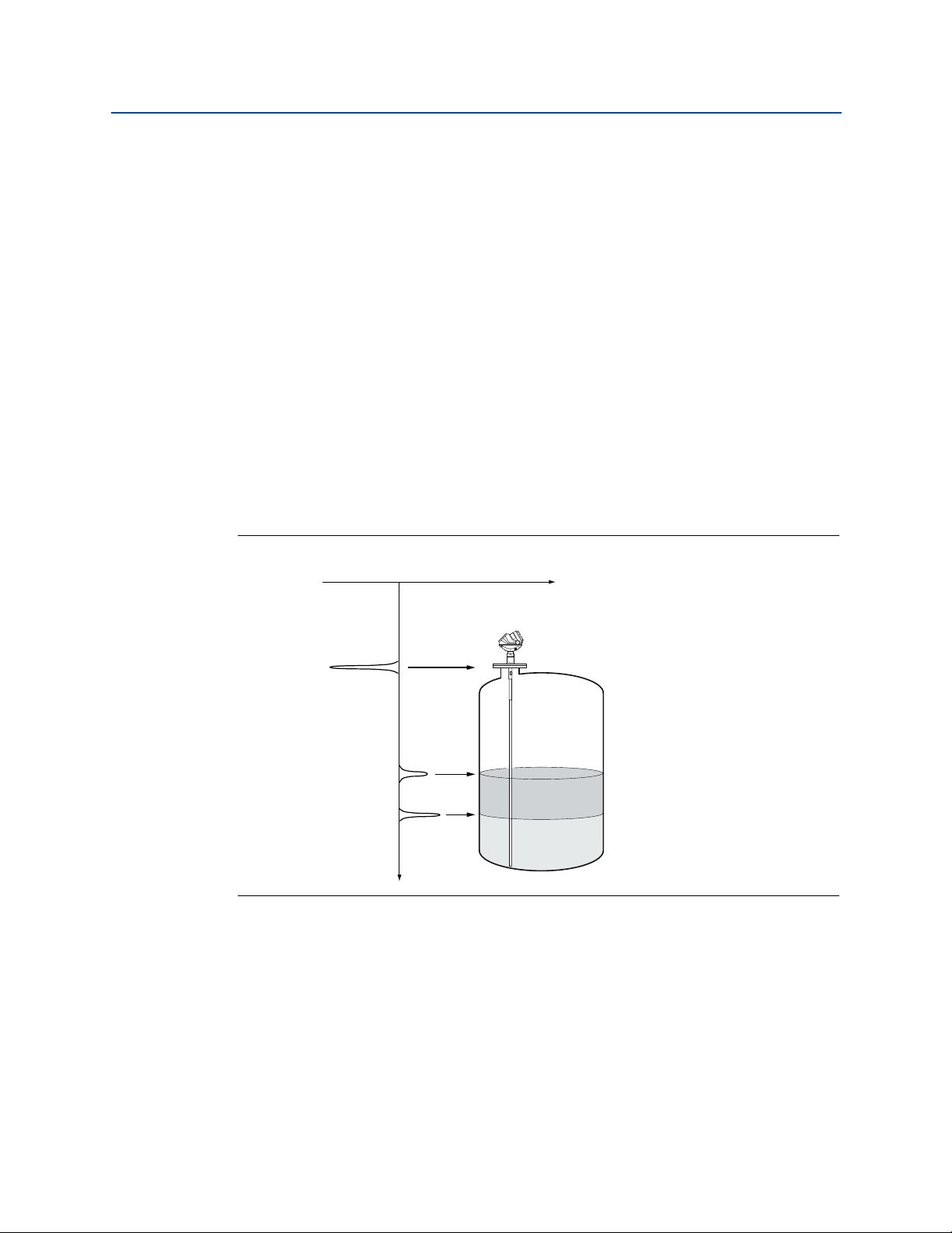
2.1 Theory of operation
The Rosemount™ 5300 Series Radar Transmitter is a smart, two-wire continuous level
transmitter based on Time Domain Reflectometry (TDR) principles. Low power nano-second-pulses are guided along an immersed probe. When a pulse reaches the surface, part of
the energy is reflected back to the transmitter, and the time difference between the
generated and reflected pulse is converted into a distance, which calculates the total level
or interface level (see Figure 2-1).
The reflectivity of the product is a key parameter for measurement performance. The
reflection intensity depends on the dielectric constant of the product. Media with a high
dielectric constant gives better reflection (signal amplitude) and a longer measuring range.
Signal amplitude thresholds are used to separate the measurement signal from disturbing
echoes and noise. The dielectric constant of the product is used for setting the
automatically calculated amplitude thresholds. See “Analyzing the measurement signal” on
page 151 for more information about threshold principle.
For interface measurements the dielectric constant of the upper product is essential for
calculating the interface level.
Reference Manual
00809-0100-4530, Rev DD
Figure 2-1. Measurement Principle
4
Tra nsmit ter O vervi ew
Reference Manual
00809-0100-4530, Rev DD
2.2 Applications
The Rosemount 5300 Series Radar Transmitter series is suited for aggregate (total) level
measurements on most liquids, semi-liquids, solids, and liquid/liquid interfaces.
Guided microwave technology offers the highest reliability and precision to ensure
measurements are virtually unaffected by temperature, pressure, vapor gas mixtures,
density, turbulence, bubbling/boiling, low level, varying dielectric media, pH, and viscosity.
Guided wave radar technology in combination with advanced signal processing makes the
Rosemount 5300 Transmitters suitable for a wide range of applications:
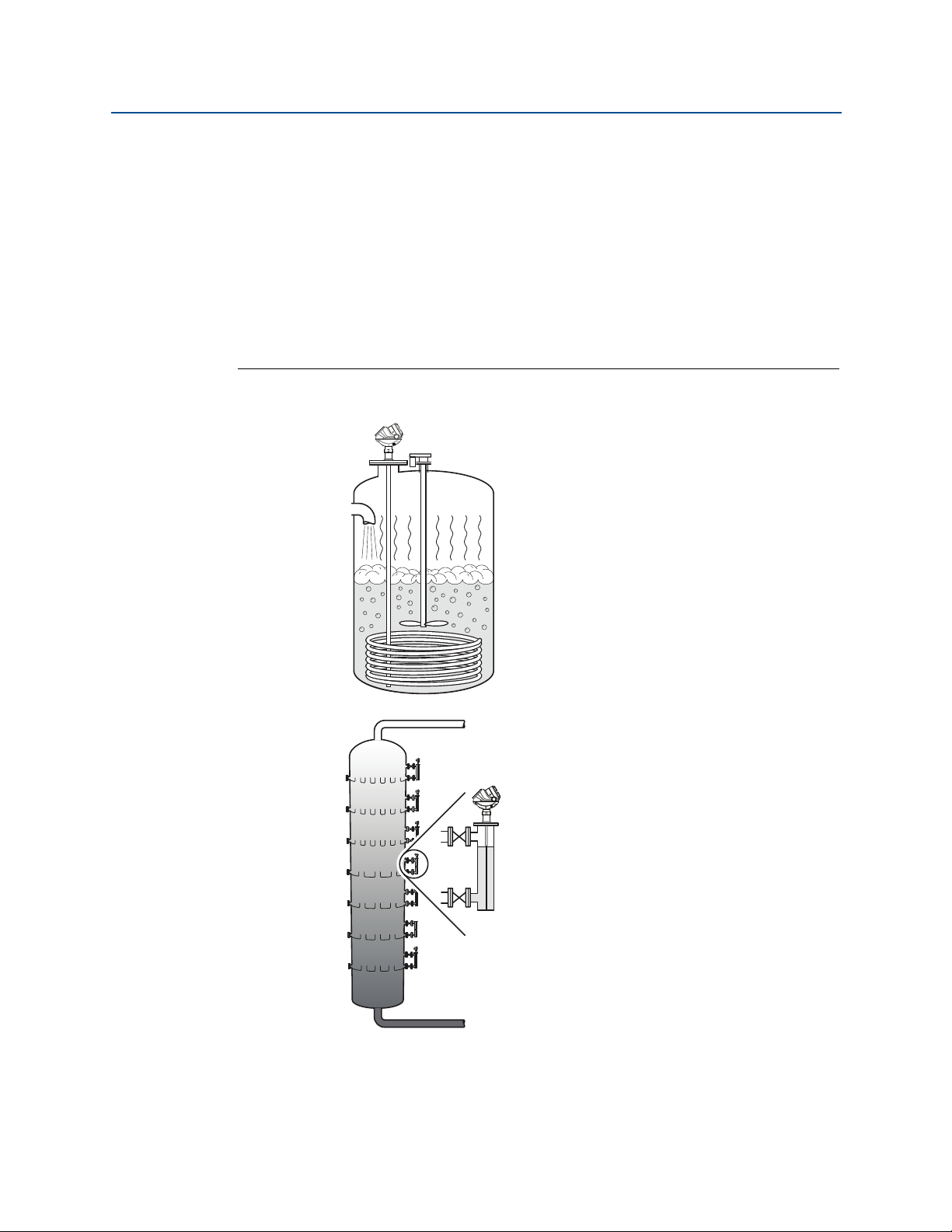
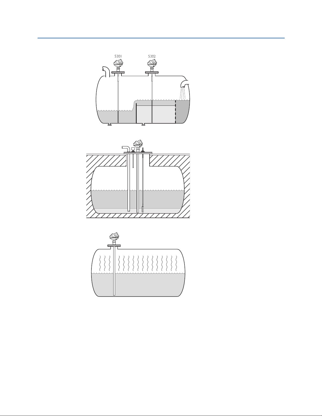
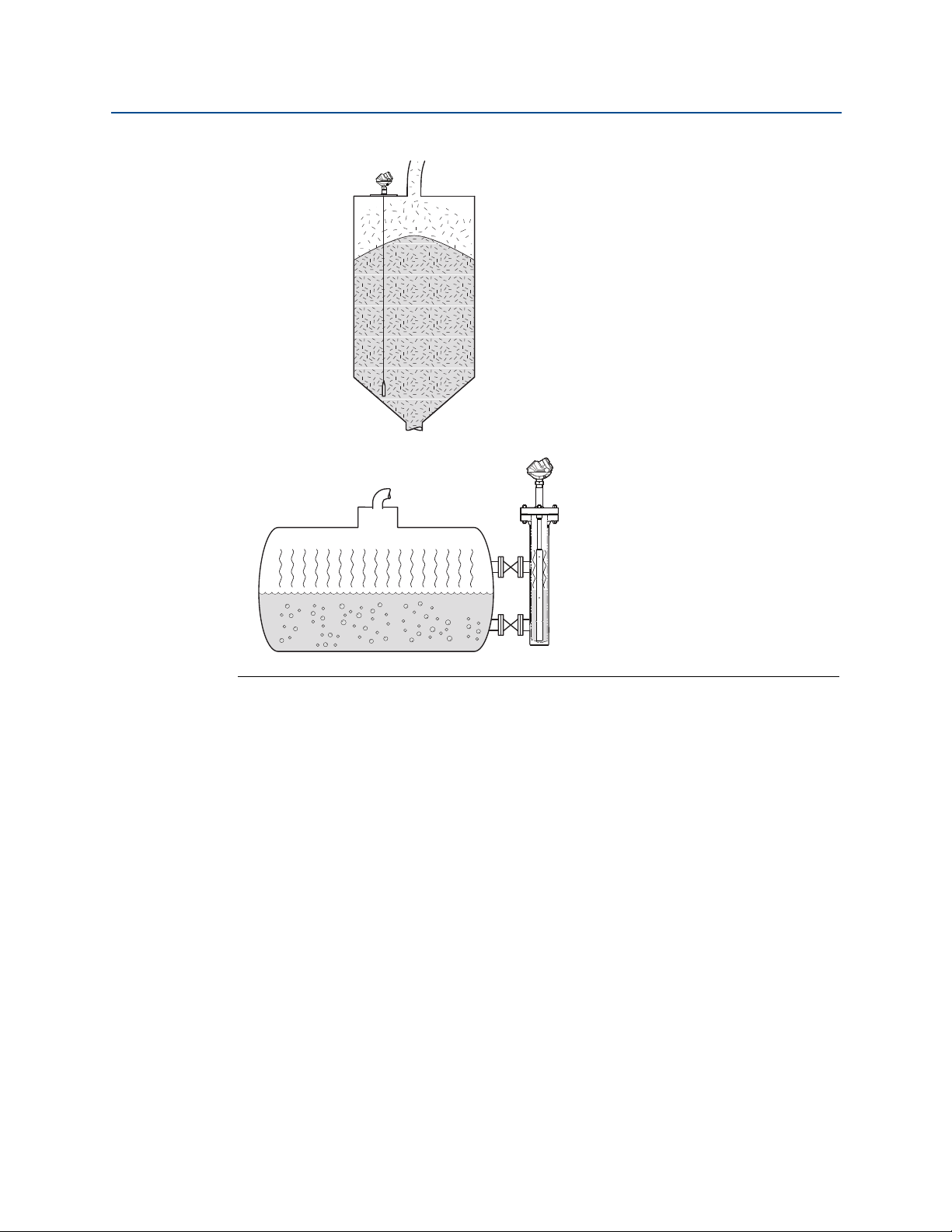
Figure 2-2. Application Examples
Transmitter Overview
May 2016
The Rosemount 5300 Transmitter
works well in boiling conditions
with vapor and turbulence. If there
are disturbing objects in the
vicinity of the transmitter, the
coaxial probe is particularly
suitable.
Transmit ter O verview
The Rosemount 5300 Series is well
suited for chamber applications,
such as distillation columns.
5
Transmitter Overview
Oil
Oil
Water
May 2016
Reference Manual
00809-0100-4530, Rev DD
The Rosemount 5302 measures
both level and interface level in a
separator tank.
The Rosemount 5300 Series is a
good choice for underground
tanks. It is installed on the top of
the tank with the radar pulse
concentrated near the probe. It
can be equipped with probes that
are unaffected by high and narrow
openings or nearby objects.
Guided wave radar technology
provides reliable measurements in
ammonia, LNG and LPG tanks.
6
Tra nsmit ter O vervi ew
Reference Manual
Rosemount 5303
00809-0100-4530, Rev DD
Transmitter Overview
May 2016
Rosemount 5303, with a flexible
single lead probe, is the solution
for solids, powders and granules.
It measures independently of dust,
angled surfaces etc.
The Rosemount 5300 Series with
Dynamic Vapor Compensation will
automatically compensate for
dielectric changes in high pressure
steam applications and maintain
the level accuracy.
Transmit ter O verview
7
Transmitter Overview
B
D
E
A
F
C
G
H
K
M
I
JL
N
O
May 2016
2.3 Components of the transmitter
The Rosemount 5300 Series Radar Transmitter has an aluminum or stainless steel (SST)
transmitter housing containing advanced electronics and software for signal processing.
SST housing is preferred for harsh environment applications, such as off-shore platforms or
other locations where the housing can be exposed to corrodents, such as salt solutions and
caustics.
The radar electronics produces an electromagnetic pulse that is guided by the probe. It
comes with flange, threaded or Tri Clamp process connection.
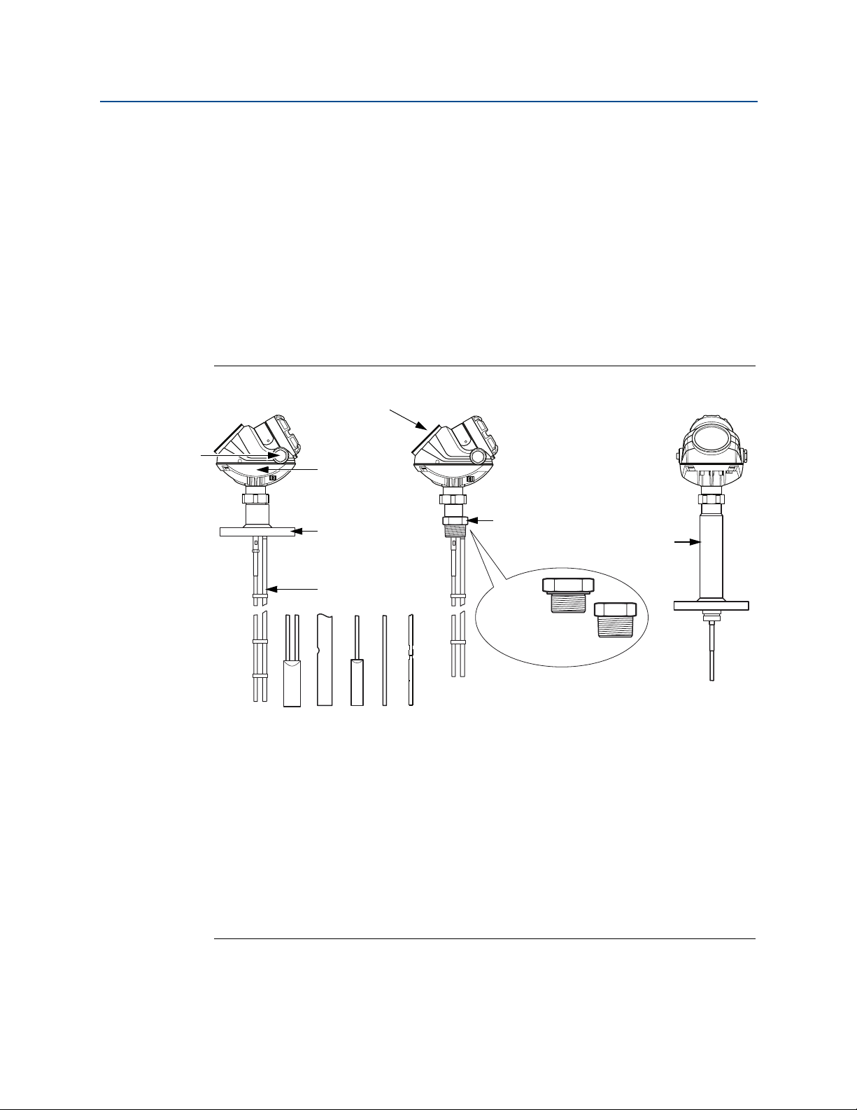
There are different probe types available for various applications: rigid twin lead, flexible
twin lead, rigid single lead, segmented rigid single lead, flexible single lead, and coaxial.
Figure 2-3. Transmitter Components
Reference Manual
00809-0100-4530, Rev DD
A. Cable entry: ½" NPT Optional adapters: M20, eurofast®, minifast
B. Radar electronics
C. Flanged process connections
D. Prob e
8
E. Dual compartment housing
F. Threaded process connections
G. BSP (G)
H. NPT
I. HTHP version
J. Rigid twin lead
K. Flexible twin lead with weight
L. Coaxial
M.Flexible single lead with weight
N. Rigid single lead
O. Segmented rigid single lead probe
®
Tra nsmit ter O vervi ew
Reference Manual
CD E
A
B
G
F
00809-0100-4530, Rev DD
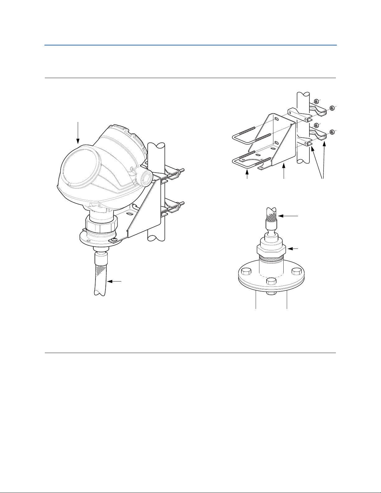
Remote housing allows for the transmitter head to be mounted separately from the probe.
Figure 2-4. Remote Housing Components
Transmitter Overview
May 2016
A. Dual compartment housing
B. Cable remote connection
C. U-bolt
D. Bracket
E. Clamping brackets
F. Cable remote connection
G. M50 nut
Transmit ter O verview
9
Transmitter Overview
C
D
E
H
B
J
G
F
I
A
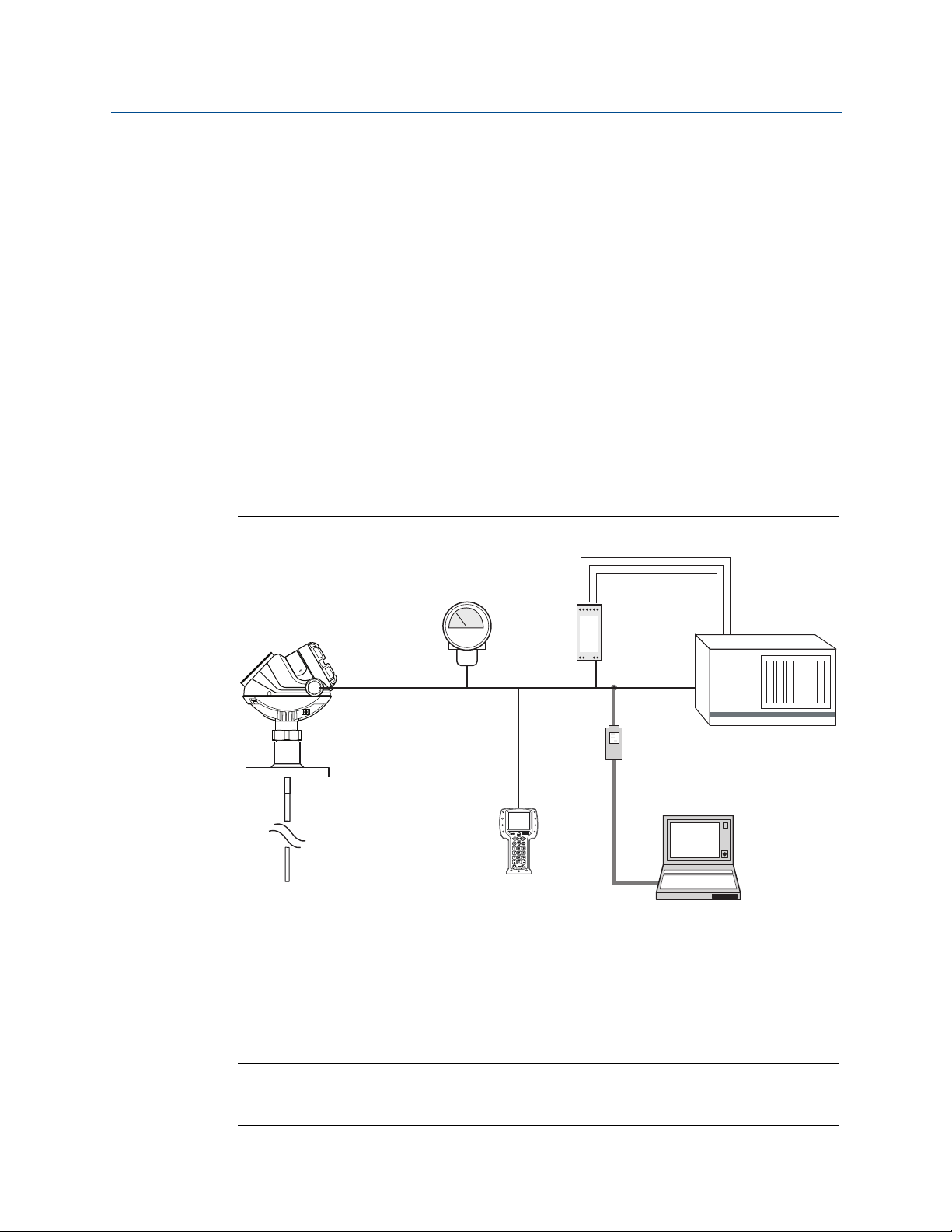
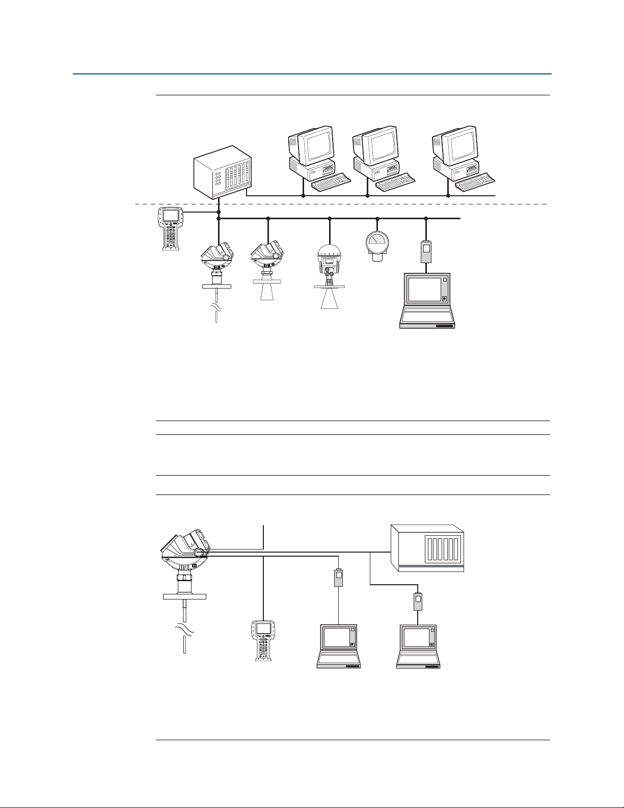
A. Integral display
B. Rosemount 5300 Series Radar Transmitter
C. 4-20 mA/HART
D. Rosemount 751 Field Signal Indicator
E. Field Communicator
F. 3 x 4-20 mA
G. Rosemount 333 HART Tri-Loop
H. HART modem
I. Rosemount Radar Master or AMS Suite
J. DCS
May 2016
2.4 System architecture
The Rosemount 5300 Series Radar Transmitter is loop-powered, and it uses the same two
wires for both power supply and output signal. The output is a 4-20 mA analog signal
superimposed with a digital HART
®
, FOUNDATION™ Fieldbus, or Modbus® signal.
Reference Manual
00809-0100-4530, Rev DD
By using the optional Rosemount 333 HART Tri-Loop
™
, the HART signal can convert up to
three additional 4-20 mA analog signals.
With the HART protocol multidrop configuration is possible. In this case, communication is
restricted to digital, since current is fixed to the 4 mA minimum value.
The transmitter can be connected to a Rosemount 751 Field Signal Indicator, or it can be
equipped with an integral display.
The transmitter can easily be configured using a Rosemount Field Communicator or a PC
with the Rosemount Radar Master software. Rosemount 5300 Series Transmitters can also
be configured with the AMS
™
Suite and DeltaV™ software, and other tools supporting
Electronic Device Description Language (EDDL) functionality.
Figure 2-5. HART System Architecture
Note
For HART communication, a minimum load resistance of 250 Ohm within the loop is
required.
10
Tra nsmit ter O vervi ew
Reference Manual
B
A
F
C
D
E
K
J
H
I
Max cable length:
6200 ft (1900 m)
G
A. 475 Field Communicator
B. Host/DCS system (e.g. DeltaV)
C. Rosemount 5300
D. Rosemount 5400
E. Rosemount 5600
F. M a in t en a n ce
G. Display
H. H2 - High speed field bus
I. H1 - Low speed field bus
J. Fieldbus modem
K. PC with Rosemount Radar Master
A
E
B
D
G
H
C
FI
A. Rosemount 5300
B. Power
C. 475 Field Communicator
D. Modbus, Levelmaster Emulation/RS-485
E. HART modem
F. PC 5300 Setup in Rosemount Radar Master
G. Control System
H. RS-232/RS-485 Converter
I. PC 5300 Setup in Rosemount Radar Master via Tunneling
00809-0100-4530, Rev DD
Figure 2-6. FOUNDATION Fieldbus System Architecture
Transmitter Overview
May 2016
Note
Intrinsically safe installations may allow fewer devices per I.S. barrier due to current
limitations.
Figure 2-7. HART to Modbus System Architecture
Transmit ter O verview
11
Transmitter Overview
May 2016
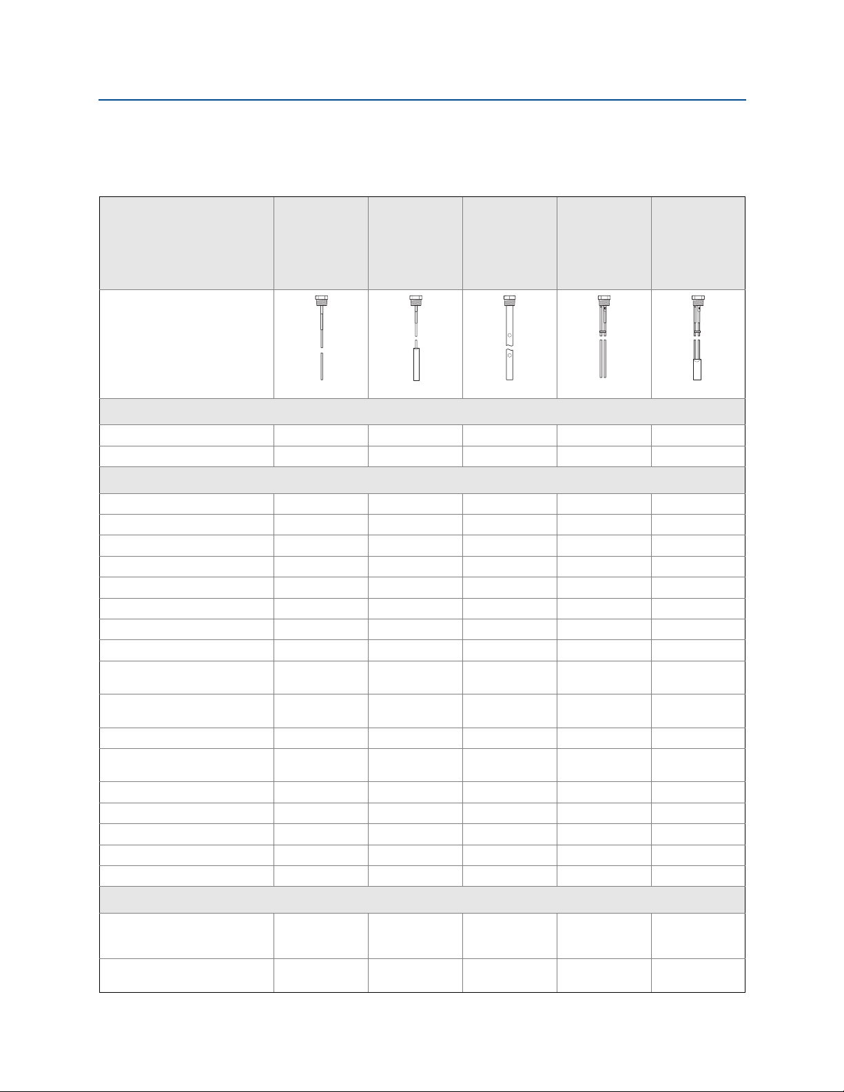
2.5 Probe selection guide
The following guidelines should be used to choose the appropriate probe for the
Rosemount 5300 Series Transmitter:
Reference Manual
00809-0100-4530, Rev DD
Rigid single
lead,
Flexible
single lead
Coaxial Rigid twin
lead
Flexible twin
lead
segmented
rigid single
lead
G = Good
NR = Not Recommended
AD = Application Dependent
(consult your local Emerson™
Process Management
representative)
Measurements
Level G G G G G
Interface (liquid/liquid)GGGGG
Process medium characteristics
Changing density GGGGG
Changing dielectric
Wide pH variations GGGGG
Pressure changes GGGGG
Temperature changes GGGGG
Condensing vapors GGGGG
Bubbling/boiling surfaces G AD G G G
Foam (mechanical avoidance) NR NR AD NR NR
Foam (top of foam
measurement)
Foam (foam and liquid
measurement)
Clean liquids GGGGG
Liquid with very low dielectric
constants, see also Ta b l e A -6 .
Coating/sticky liquids AD
Viscous liquids AD
Crystallizing liquids AD AD NR NR NR
Solids, granules, powders AD G NR NR NR
Fibrous liquids G G NR NR NR
(1)
GGGGG
AD AD NR AD AD
AD AD NR AD AD
GG
(3)
(3)
(2)
AD NR NR NR
GNRADAD
GGG
(2)
Tank environment considerations
Probe is close (<12 in./30 cm)
to tank wall / disturbing
objects
Probe might touch tank wall,
nozzle or disturbing objects
12
AD AD G G G
NR NR G NR NR
Tra nsmit ter O vervi ew

Reference Manual
00809-0100-4530, Rev DD
Transmitter Overview
May 2016
Rigid single
lead,
Flexible
single lead
Coaxial Rigid twin
lead
Flexible twin
lead
segmented
rigid single
lead
G = Good
NR = Not Recommended
AD = Application Dependent
(consult your local Emerson
Process Management
representative)
Tur b ul en ce G A D G G A D
Turbulent conditions causing
breaking forces
Tall, narrow nozzles AD AD G AD AD
Angled or slanted surface
(viscous or solids materials)
Liquid or vapor spray might
touch probe above surface
Disturbing Electromagnetic
interference in tank
Cleanability of probe G G NR AD AD
1. For overall level applications, a changing dielectric has no effect on the measurement. For interface measurements, a changing dielectric for the top
fluid will degrade the accuracy of the interface measurement.
2. Limited measuring range.
3. For viscous or sticky applications, it is not recommended to use centering discs mounted along the probe.
NR AD NR NR AD
G G NR AD AD
NR NR G NR NR
AD AD G AD AD
Transmit ter O verview
13

Transmitter Overview
4mA
20mA
Reduced accuracy
Reduced accuracy
Range 0 -100 %
Upper Reference Point
Upper Blind Zone
Lower Blind Zone
Lower Reference Point
May 2016
2.6 Measuring range
The measuring range depends on probe type, dielectric constant of the product and
installation environment, and is limited by the Blind Zones at the very top and bottom of the
probe. In the Blind Zones, the accuracy exceeds ±1.18 in. (30 mm), and measurements may
not be possible. Measurements close to the Blind Zones will have reduced accuracy.
Figure 2-8 illustrates how the measuring range is related to the Blind Zones and the areas
with reduced accuracy. Values for different probe types and dielectric constants are
presented in section “Accuracy over measuring range” on page 230.
Figure 2-8. Blind Zones and Areas with Reduced Accuracy
Reference Manual
00809-0100-4530, Rev DD
14
Note
Measurements may not be possible in the Blind Zones, and measurements close to the Blind
Zones will have reduced accuracy. Therefore, the 4-20 mA points should be configured
outside these zones.
Tra nsmit ter O vervi ew

Reference Manual
00809-0100-4530, Rev DD
2.7 Process characteristics
The Rosemount 5300 Series has high sensitivity because of its advanced signal processing
and high signal to noise ratio. This makes it able to handle various disturbances, however,
the following circumstances should be considered before mounting the transmitter.
2.7.1 Contamination/product build-up
Heavy contamination or product build-up on the probe should be avoided since it may
decrease the sensitivity of the transmitter and lead to measurement errors. In viscous or
sticky applications, periodic cleaning may be required.
For viscous or sticky applications, it is important to choose a suitable probe. For detailed
information on the maximum recommended viscosity and coating, see Tabl e A-5 on
page 226.
Maximum measurement error due to contamination is 1-10% depending on probe type,
dielectric constant, contamination thickness and contamination height above product
surface.
Transmitter Overview
May 2016
Signal Quality Metrics (SQM) diagnostic option can give an indication of how good the
surface signal is compared to the noise, and when to clean the probe.
2.7.2 Bridging
Heavy product build-up results in bridging between the two probes in a twin lead version,
or between the pipe and inner rod for coaxial probes, and may cause erroneous level
readings, so it must be prevented. A single lead probe is recommended in these situations.
2.7.3 Foam
The Rosemount 5300 Series Radar Transmitter measurement in foamy applications
depends on the foam properties; light and airy or dense and heavy, high or low dielectrics,
etc. If the foam is conductive and creamy, the transmitter may measure the surface of the
foam. If the foam is less conductive the microwaves may penetrate the foam and measure
the liquid surface.
2.7.4 Vapor
In some applications, such as high pressure boiling water, there is a heavy vapor above the
product surface that could influence the level measurement. The Rosemount 5300 Series
Radar Transmitter can be configured to compensate for the influence of vapor.
2.7.5 Boiling hydrocarbons
Transmit ter O verview
For products with very low dielectric constants, such as boiling hydrocarbons and solids, the
threshold may need to be lowered, and/or the Probe End Projection (PEP) function
activated.
15
Transmitter Overview
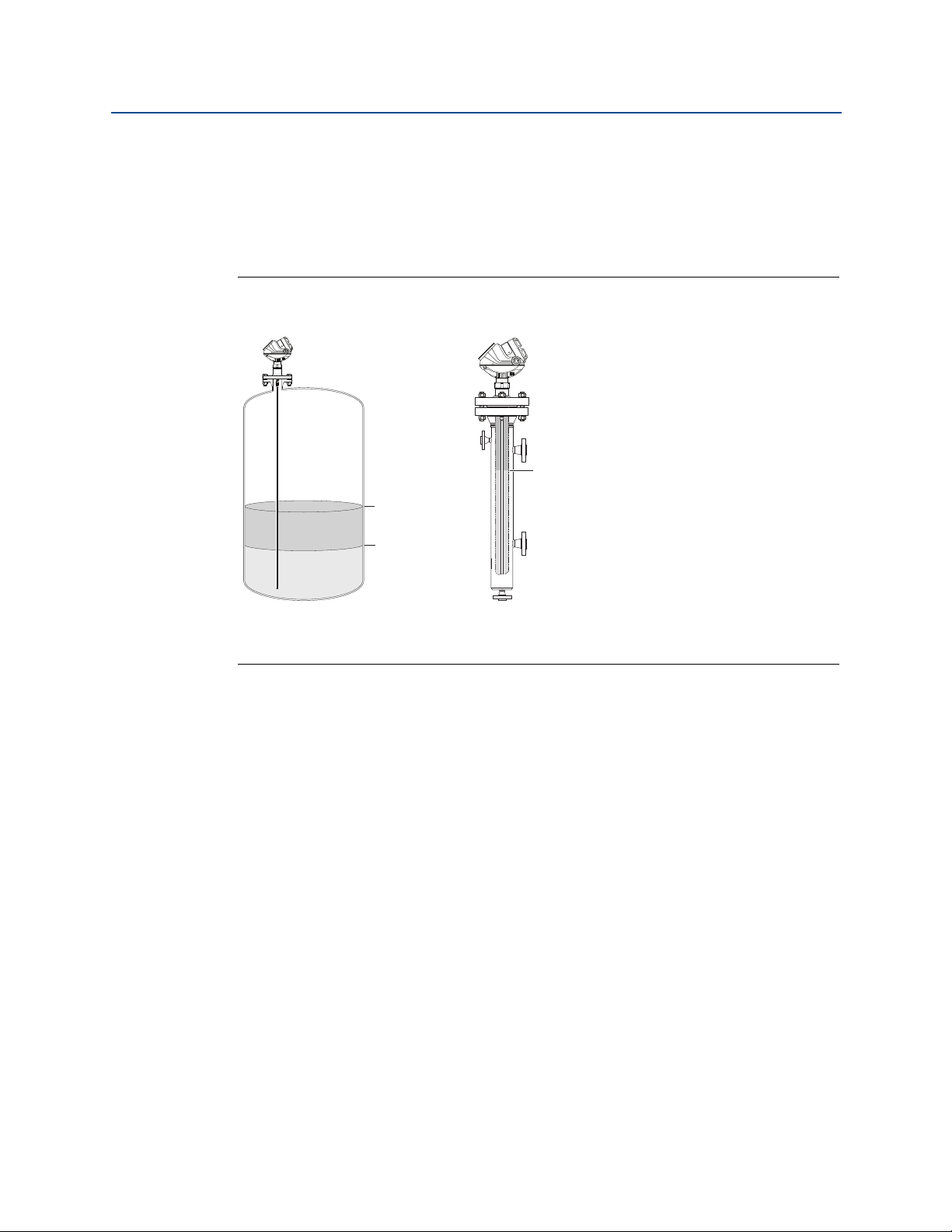
Product Level and
Interface Level
Product Level
Interface Level
Interface Level
Rosemo unt
5302
Rosemo unt
5301
Interface Level with
submerged probe
May 2016
2.7.6 Interface
Rosemount 5302 is the ideal choice for measuring the level of oil, and the interface of oil
and water, or other liquids with significant dielectric differences. Rosemount 5301 can also
be used for interface measurement in applications where the probe is fully submerged in
the liquid.
Figure 2-9. Interface Level Measurement
Reference Manual
00809-0100-4530, Rev DD
For measuring interface level, the transmitter uses the residual wave of the first reflection.
Part of the wave, not reflected at the upper product surface, continues until it is reflected at
the lower product surface. The speed of this wave depends fully on the dielectric constant
of the upper product.
All probes can be used for measuring interfaces. Single probes are the preferred choice in
almost all applications but depending on the application and installation geometries a
coaxial probe or a twin probe may be a better fit.
The maximum allowable upper product thickness/measuring range is primarily determined
by the dielectric constants of the two liquids. Typical applications include interfaces
between oil/oil-like and water/water-like liquids. For such applications, the upper product
dielectric constant is low (<3) and the lower product dielectric constant is high (>20). Refer
to “Interface measurements” on page 224 for further interface application guidelines.
Emulsion layers
Sometimes an emulsion layer (mix of the products) forms between the two products and
can affect interface measurements. For assistance with emulsion applications, consult your
local Emerson Process Management representative.
16
Tra nsmit ter O vervi ew
 Loading...