

Rosemount 5081 Reference Manual
00809-0100-3581, Rev AC
Rosemount™ 5081
Explosion Proof, Single-Input Intelligent Transmitter
Reference Manual
October 2019

Essential instructions
Read this page before proceeding!
Emerson designs, manufactures, and tests its products to meet many national and international standards. Because these
instruments are sophisticated technical products, you must properly install, use, and maintain them to ensure they continue to
operate within their normal specifications. The following instructions must be adhered to and integrated into your safety program
when installing, using, and maintaining Emerson products. Failure to follow the proper instructions may cause any one of the
following situations to occur: loss of life, personal injury, property damage, damage to this instrument, and warranty invalidation.
• Read all instructions prior to installing, operating, and servicing the product.
• If this Reference Manual is not the correct one, call 1-800-854-8257 or 949-757-8500 to request the correct Reference
Manual. Save this Reference Manual for future reference.
• If you do not understand any of the instructions, contact your Emerson representative for clarification.
• Follow all warnings, cautions, and instructions marked on and supplied with the product.
• Inform and educate your personnel in the proper installation, operation, and maintenance of the product.
• Install equipment as specified in the installation instructions of the appropriate Reference Manual and per applicable local and
national codes. Connect all products to the proper electrical and pressure sources.
• To ensure proper performance, use qualified personnel to install, operate, update, program, and maintain the product.
• When replacement parts are required, ensure that qualified people use replacement parts specified by Emerson.
Unauthorized parts and procedures can affect the product's performance, place the safe operation of your process at risk, and
VOID YOUR WARRANTY. Look-alike substitutions may result in fire, electrical hazards, or improper operation.
• Ensure that all equipment doors are closed and protective covers are in place, except when maintenance is being performed
by qualified people, to prevent electrical shock and personal injury.
WARNING
Physical access
Unauthorized personnel may potentially cause significant damage to and/or misconfiguration of end users’ equipment. This could
be intentional or unintentional and needs to be protected against.
Physical security is an important part of any security program and fundamental to protecting your system. Restrict physical access
by unauthorized personnel to protect end users’ assets. This is true for all systems used within the facility.
Notice
ROSEMOUNT (“SELLER”) SHALL NOT BE LIABLE FOR TECHNICAL OR EDITORIAL ERRORS IN THIS MANUAL OR OMISSIONS FROM
THIS MANUAL. SELLER MAKES NO WARRANTIES, EXPRESSED OR IMPLIED, INCLUDING THE IMPLIED WARRANTIES OF
MERCHANTABILITY AND FITNESS FOR A PARTICULAR PURPOSE, WITH RESPECT TO THIS MANUAL AND, IN NO EVENT, SHALL
SELLER BE LIABLE FOR ANY SPECIAL OR CONSEQUENTIAL DAMAGES INCLUDING, BUT NOT LIMITED TO, LOSS OF PRODUCTION,
LOSS OF PROFITS, ETC.
PRODUCT NAMES USED HEREIN ARE FOR MANUFACTURER OR SUPPLIER IDENTIFICATION ONLY AND MAY BE TRADEMARKS/
REGISTERED TRADEMARKS OF THESE COMPANIES.
THE CONTENTS OF THIS PUBLICATION ARE PRESENTED FOR INFORMATIONAL PURPOSES ONLY, AND WHILE EVERY EFFORT HAS
BEEN MADE TO ENSURE THEIR ACCURACY, THEY ARE NOT TO BE CONSTRUED AS WARRANTIES OR GUARANTEES, EXPRESSED OR
IMPLIED, REGARDING THE PRODUCTS OR SERVICES DESCRIBED HEREIN OR THEIR USE OR APPLICABILITY. WE RESERVE THE RIGHT
TO MODIFY OR IMPROVE THE DESIGNS OR SPECIFICATIONS OF SUCH PRODUCTS AT ANY TIME.
SELLER DOES NOT ASSUME RESPONSIBILITY FOR THE SELECTION, USE, OR MAINTENANCE OF ANY PRODUCT. RESPONSIBILITY FOR
PROPER SELECTION, USE, AND MAINTENANCE OF ANY SELLER PRODUCT REMAINS SOLELY WITH THE PURCHASER AND END-USER.
Warranty
LIMITED WARRANTY: Subject to the limitations contained in Section 2 herein and except as otherwise expressly provided
1.
herein, Rosemount (“Seller”) warrants that the firmware will execute the programming instructions provided by Seller
and that the Goods manufactured or Services provided by Seller will be free from defects in materials or workmanship
under normal use and care until the expiration of the applicable warranty period. Goods are warranted for twelve (12)
months from the date of initial installation or eighteen (18) months from the date of shipment by Seller, whichever period
expires first. Consumables and Services are warranted for a period of 90 days from the date of shipment or completion of
the Services. Products purchased by Seller from a third party for resale to Buyer (“Resale Products”) shall carry only the
2

warranty extended by the original manufacturer. Buyer agrees that Seller has no liability for Resale Products beyond
making a reasonable commercial effort to arrange for procurement and shipping of the Resale Products. If Buyer
discovers any warranty defects and notifies Seller thereof in writing during the applicable warranty period, Seller shall, at
its option, promptly correct any errors that are found by Seller in the firmware or Services, or repair or replace F.O.B. point
of manufacture that portion of the Goods or firmware found by Seller to be defective, or refund the purchase price of the
defective portion of the Goods/Services. All replacements or repairs necessitated by inadequate maintenance, normal
wear and usage, unsuitable power sources, unsuitable environmental conditions, accident, misuse, improper installation,
modification, repair, storage or handling, or any other cause not the fault of Seller are not covered by this limited
warranty, and shall be at Buyer's expense. Seller shall not be obligated to pay any costs or charges incurred by Buyer or any
other party except as may be agreed upon in writing in advance by an authorized Seller representative. All costs of
dismantling, reinstallation and freight, and the time and expenses of Seller's personnel for site travel and diagnosis under
this warranty clause shall be borne by Buyer unless accepted in writing by Seller. Goods repaired and parts replaced during
the warranty period shall be in warranty for the remainder of the original warranty period or ninety (90) days, whichever is
longer. This limited warranty is the only warranty made by Seller and can be amended only in a writing signed by an
authorized representative of Seller. Except as otherwise expressly provided in the Agreement, THERE ARE NO
REPRESENTATIONS OR WARRANTIES OF ANY KIND, EXPRESSED OR IMPLIED, AS TO MERCHANTABILITY, FITNESS FOR
PARTICULAR PURPOSE, OR ANY OTHER MATTER WITH RESPECT TO ANY OF THE GOODS OR SERVICES. It is understood
that corrosion or erosion of materials is not covered by our guarantee.
LIMITATION OF REMEDY AND LIABILITY: SELLER SHALL NOT BE LIABLE FOR DAMAGES CAUSED BY DELAY IN
2.
PERFORMANCE. THE SOLE AND EXCLUSIVE REMEDY FOR BREACH OF WARRANTY HEREUNDER SHALL BE LIMITED TO
REPAIR, CORRECTION, REPLACEMENT, OR REFUND OF PURCHASE PRICE UNDER THE LIMITED WARRANTY CLAUSE IN
SECTION 1 HEREIN. IN NO EVENT, REGARDLESS OF THE FORM OF THE CLAIM OR CAUSE OF ACTION (WHETHER BASED IN
CONTRACT, INFRINGEMENT, NEGLIGENCE, STRICT LIABILITY, OTHER TORT, OR OTHERWISE), SHALL SELLER'S LIABILITY TO
BUYER AND/OR ITS CUSTOMERS EXCEED THE PRICE TO BUYER OF THE SPECIFIC GOODS MANUFACTURED OR SERVICES
PROVIDED BY SELLER GIVING RISE TO THE CLAIM OR CAUSE OF ACTION. BUYER AGREES THAT IN NO EVENT SHALL
SELLER'S LIABILITY TO BUYER AND/OR ITS CUSTOMERS EXTEND TO INCLUDE INCIDENTAL, CONSEQUENTIAL OR PUNITIVE
DAMAGES. THE TERM “CONSEQUENTIAL DAMAGES” SHALL INCLUDE, BUT NOT BE LIMITED TO, LOSS OF ANTICIPATED
PROFITS, LOSS OF USE, LOSS OF REVENUE, AND COST OF CAPITAL.
3

4

Reference Manual Contents
00809-0100-3581 October 2019
Contents
Chapter 1 Start-up......................................................................................................................... 7
Chapter 2 Description and specifications........................................................................................9
2.1 Features and applications................................................................................................................. 9
2.2 General specifications.......................................................................................................................9
2.3 Rosemount 5081 - (A/P/C/T) product certifications........................................................................ 12
2.4 Functional specifications................................................................................................................ 15
2.5 Ordering information..................................................................................................................... 17
Chapter 3 Install...........................................................................................................................19
3.1 Unpack and inspect........................................................................................................................ 19
3.2 Installation guidelines.....................................................................................................................19
3.3 Orient the display board................................................................................................................. 20
3.4 Mount on a flat surface................................................................................................................... 21
3.5 Mount on a pipe............................................................................................................................. 22
Chapter 4 Wire............................................................................................................................ 25
4.1 Wiring overview............................................................................................................................. 25
4.2 Power supply/current loop............................................................................................................. 25
Chapter 5 Display and operate..................................................................................................... 29
5.1 User interface and main display...................................................................................................... 29
5.2 Infrared remote control (IRC)..........................................................................................................30
5.3 Menu system..................................................................................................................................31
Chapter 6 Programming basics.................................................................................................... 43
6.1 Programming................................................................................................................................. 43
6.2 Test 4-20 mA outputs and current generated during hold and faults.............................................. 43
6.3 Correct temperature...................................................................................................................... 45
6.4 Set up a custom curve (conductivity measurements only).............................................................. 46
6.5 Restore to factory default settings..................................................................................................47
6.6 Set access (security) code...............................................................................................................47
6.7 Activate or deactivate HOLD...........................................................................................................48
Chapter 7 Measurements............................................................................................................. 49
7.1 Calibrating pH sensors....................................................................................................................49
7.2 Calibrating oxidation reduction potential (ORP) sensors.................................................................52
7.3 Calibrating contacting and toroidal conductivity sensors................................................................54
7.4 Calibrating dissolved oxygen, ozone, free chlorine, total chlorine, and ozone sensors.................... 56
Chapter 8 Diagnostics and troubleshooting..................................................................................61
8.1 Warning and fault messages...........................................................................................................61
Reference Manual v

Contents Reference Manual
October 2019 00809-0100-3581
8.2 pH/ORP diagnostics and troubleshooting.......................................................................................62
8.3 Contacting and toroidal conductivity diagnostics and troubleshooting.......................................... 89
8.4 Chlorine, dissolved oxygen, and ozone diagnostics.......................................................................100
8.5 Chlorine, dissolved oxygen, and ozone troubleshooting...............................................................103
8.6 Factory assistance and repairs...................................................................................................... 129
Chapter 9 Digital communications............................................................................................. 131
9.1 HART® communications...............................................................................................................131
9.2 FOUNDATION™ Fieldbus communication..........................................................................................132
9.3 Asset Management Solutions....................................................................................................... 134
Chapter 10 Return of material...................................................................................................... 137
10.1 General information................................................................................................................... 137
10.2 Warranty repair.......................................................................................................................... 137
10.3 Non-warranty repair................................................................................................................... 137
Appendix A Engineering Drawings................................................................................................139
vi Rosemount 5081

Reference Manual Start-up
00809-0100-3581 October 2019
1 Start-up
Procedure
1. Using the infrared remote control (IRC), press PROG, NEXT, NEXT, and ENTER in this
order.
2. Select the measurement type and unit of measurement.
3. Use the arrow keys to toggle between Celsius and Fahrenheit.
4. Press ENTER and then RESET.
5. Press PROG, NEXT, and ENTER in this order.
6. Use the arrow keys to toggle T AUTO between ON or OFF.
This determines whether the transmitter uses the process temperature (ON) or a
manual temperature (OFF).
7. Press ENTER.
8. If you select OFF, enter the manual temperature desired using the arrow keys.
9. Press ENTER.
Reference Manual 7

Start-up Reference Manual
October 2019 00809-0100-3581
8 Rosemount 5081

Reference Manual Description and specifications
00809-0100-3581 October 2019
2 Description and specifications
2.1 Features and applications
The Rosemount™ 5081 includes the following features:
General
The Rosemount 5081 explosion-proof transmitter is a loop powered device with a robust
design that serves several industrial, commercial, and municipal applications. It offers a
local operator interface (LOI) that can display values from a single measurement input.
This transmitter is compatible with a multitude of analytical sensors.
Analytical measurements
• pH/ORP
• Contacting conductivity
• Toroidal conductivity
• Dissolved oxygen
• Ozone
• Chlorine
Maintenance features
• Automatic two-point buffer calibration routine
• Automatic recognition of resistance temperature device (RTD)
• Sensor diagnostics
Diagnostics
Continuous monitoring of sensor performance along with warnings and fault messages to
alert the user of failures.
Enclosure
Explosion-proof and corrosion resistant
2.2 General specifications
Table 2-1: General Specifications
Housing Cast aluminum with epoxy coating. NEMA® 4X(IP65) and NEMA7B. Neoprene
O-ring seals.
Dimensions 6.3 x 6.9 x 6.4 in. (160.5 x 175.3 x 161.3 mm) See the engineering drawings in
Engineering Drawings.
Conduit openings ¾-in. female national pipe thread (FNPT)
Ambient temperature -4 to 149 °F (-20 to 65 °C)
Reference Manual 9

Description and specifications Reference Manual
October 2019 00809-0100-3581
Table 2-1: General Specifications (continued)
Storage temperature -22 to 176 °F (-30 to 80 °C)
Relative humidity 0 to 95% (non-condensing)
Weight / shipping weight 10 lb./11 lb. (4.5 kg/5.0 kg)
Display First line: 7 segment LCD, 0.8 in. (20 mm) high. This line shows process
variables (pH/ORP, contacting conductivity, toroidal conductivity, etc.)
Second line: 7 segment LCD, 0.3 in. (7 mm) high. This line shows process
temperature, output current, warnings, faults, and messages during
calibration/programming.
Display board can be rotated 90 degrees clockwise or counterclockwise if
desired.
Temperature resolution 0.1 °C
Hazardous location approval For details, see Rosemount 5081 - (A/P/C/T) product certifications.
RFI/EMI Meets all industrial requirements of EN61326.
Diagnostics (may slightly vary based
on measurement type)
• Calibration error
• Low temperature error
• High temperature error
• Sensor failure
• Line failure
• CPU failure
• Calibration error
• Zero error
• Temperature slope error
• Sensor failure
• ROM failure
• Input warning
Once one of the above warnings/faults are diagnosed, the LOI will display a
message describing the failure detected.
Table 2-2: HART® Digital Communications
Power and load requirements Supply voltage at the transmitter terminals should be at least 12 Vdc. Power
supply voltage should cover the voltage drop on the cable plus the external
load resistor required for HART communications (250 Ohms minimum).
Minimum power voltage is 12 Vdc. Maximum power voltage is 42.4 Vdc
(30 Vdc for intrinsically safe operation). Figure 4-1 shows the supply voltage
required to maintain 12 Vdc (upper line) and 30 Vdc (lower line) at the
transmitter terminals when the current is 22 mA.
Analog output Two-wire, 4-20 mA output with superimposed HART digital signal, scalable
over the operating range of the sensor.
Output accuracy ±0.05 mA
10 Rosemount 5081

Reference Manual Description and specifications
00809-0100-3581 October 2019
Table 2-2: HART® Digital Communications (continued)
Variables assignable to • pH
• Temperature
• mV
• Glass impedance
• Reference impedance
• RTD resistance
• Oxidation reduction potential (ORP)
• Conductivity
• Resistivity
• Concentration
• Raw conductivity
• Chlorine
• Dissolved oxygen
• Dissolved ozone
Table 2-3: FOUNDATION™ Fieldbus Digital Communications
Power and load requirements A power supply voltage of 9-32 Vdc at 22 mA is required.
AI blocks assignable to • pH
• Temperature
• mV
• Glass impedance
• Reference impedance
• RTD resistance
• ORP
• Conductivity
• Resistivity
• Concentration
• Raw conductivity
• Chlorine
• Dissolved oxygen
• Dissolved ozone
Reference Manual 11

Description and specifications Reference Manual
October 2019 00809-0100-3581
2.3 Rosemount 5081 - (A/P/C/T) product certifications
Rev 1.0
2.3.1 European Directive Information
A copy of the EU Declaration of Conformity can be found at the end of the Quick Start
Guide. The most recent revision of the EU Declaration of Conformity can be found at
Emerson.com/Rosemount.
2.3.2 Ordinary Location Certification
As standard, the Power Module has been examined and tested to determine that the
design meets the basic electrical, mechanical, and fire protection requirements by a
nationally recognized test laboratory (NRTL) as accredited by the Federal Occupational
Safety and Health Administration (OSHA).
2.3.3
2.3.4
Installing equipment in North America
The US National Electrical Code® (NEC) and the Canadian Electrical Code (CEC) permit the
use of Division marked equipment in Zones and Zone marked equipment in Divisions. The
marking must be suitable for the area classification, gas, and temperature class. This
information is clearly defined in the respective codes.
USA
FM hazardous locations
Certificate
Standards
Markings
FM17US0021X
FM Class 3600:2011, FM Class 3610:2015, FM Class 3611:2016 FM Class
3615:2006, FM Class 3810:2005, ANSI/NEMA 250:1991
Intrinsically safe for use in Class I, II, and III, Division 1, Groups A, B,
C, D, E, F, and G; T4 Ta = -20 °C to 70 °C; per control drawing numbers
1400676; 1400677
Nonincendive for Class I, Division 2, Groups A, B, C, and D; T4 Ta = -20 °C
to 70 °C; per control drawing numbers 1400676; 1400677
Dust-ignitionproof for use in Class II and Class III, Division 1, Groups E, F,
and G; T6 Ta = -20 °C to 70 °C;per control drawing number 1400678
Explosionproof for use in Class I, Div 1, Groups B, C, and D; T6 Ta = -20 °C
to 70 °C; per control drawing number 1400678
Type 4X
Special Conditions for Safe Use (X):
1. The Rosemount 5081-T conductivity transmitters shall only be used with the
Rosemount 222, 225, 226, 228 (1 in. and 2 in. only) and 245 toroidal sensors.
12 Rosemount 5081

Reference Manual Description and specifications
00809-0100-3581 October 2019
2.3.5 Canada
CSA hazardous locations
Certificate
Standards
Markings
2.3.6 Europe
Rosemount 5081-A and 5081-P liquid transmitters
ATEX
1132747
C22.2 No. 0-M1987, C22.2 No. 25-1966, C22.2 No. 30-M1986 C22.2
No. 94-M91, C22.2 No 142-M1987, C22.2 No. 157-92, C22.2 No. 213M1987
Intrinsically safe for Class I Groups A, B, C, and D; Class II Groups E,
F, and G; Class III; T4 Tamb = 70 °C, per installation drawing 1400674
and 1400675
Non-incendive for Class I, Div. 2 for Groups A, B, C, and D; Class II, Div. 2,
Groups F and G; Class III; T4 Tamb = 70 °C, per installation drawing
1400674 and 1400675 (Rosemount 5081-A/P/C/T) and per 1700462
(Rosemount 5081-T)
Explosion-proof for Class I, Groups B, C, and D; Class II, Groups E, F, and
G, Class III, T6 Tamb = 70 °C
Type 4X
Certificate
Standards
Markings
Special Conditions for Safe Use (X):
1. The Rosemount 5081 enclosure may be made of aluminum alloy and given a
protective polyurethane paint finish; however, care should be taken to protect it
from impact or abrasion of located in a zone 0.
BAS02ATEX1284X
EN 60079-0:2012+A11:2013
EN 60079-11:2012
II 1 G
Ex ia IIC T4 Ga
(-20 °C ≤ Ta ≤ +65 °C)
Rosemount 5081-C liquid transmitter
ATEX
Certificate
Standards
Baseefa03ATEX0099X
EN 60079-0:2012+A11:2013
EN 60079-11:2012
Reference Manual 13

Description and specifications Reference Manual
October 2019 00809-0100-3581
Markings
Special Conditions for Safe Use (X):
1. The equipment enclosure may contain light metals. The equipment must be
installed in such a manner as to minimize the risk of impact or friction with other
metal surfaces.
II 1 G
Ex ia IIC T4 Ga
(-20 °C ≤ Ta ≤ +65 °C)
Rosemount 5081-T liquid transmitter
ATEX
Certificate
Standards
Markings
Special Conditions for Safe Use (X):
Baseefa03ATEX0399X
EN 60079-0:2012+A11:2013
EN 60079-11:2012
II 1 G
Ex ia IIC T4 Ga
(-20 °C ≤ Ta ≤ +65°C)
2.3.7
1. The equipment may contain light metals. The equipment must be installed in such
a manner as to minimize the risk or impact or friction with other metal surfaces.
International
IECEx
Certificate
Standards
Markings
Special Conditions for Safe Use (X):
1. The Rosemount 5081 enclosure may be made of aluminum alloy and given a
protective polyurethane paint finish; however, care should be taken to protect it
from impact or abrasion if located in a zone 0 environment.
IECEx BAS 09.0159X
IEC 60079-0:2011
IEC 60079-11:2011
Ex ia IIC T4 Ga
(-20 °C ≤ Ta ≤ +65°C)
14 Rosemount 5081

Reference Manual Description and specifications
00809-0100-3581 October 2019
2.4 Functional specifications
The sections below display the specifications for measuring different substances with the
Rosemount 5081.
2.4.1 pH/ORP specifications
pH range 0 to 14
ORP range -1400 to +1400 mV
Calibration/standardization The automatic buffer recognition uses stored buffer values and
their temperature curves for the most common buffer standards
available worldwide. The transmitter also performs a stabilization
check on the sensor in each buffer. To make a manual two-point
calibration, immerse the sensor in two different buffer solutions
and enter the pH values. The microprocessor automatically
calculates the slope which is used for self-diagnostics. The
transmitter displays an error message if the pH sensor is faulty.
The operator can read the slope on the display and/or manually
adjust it if desired. To complete an on-line, one-point
standardization process, enter the pH or ORP value of a grab
sample as measured by a lab reference.
Preamplifier location Use a preamplifier to convert the high impedance pH electrode
signal to a low impedance signal for transmitter use. Use the
transmitter's integral preamplifier when the sensor to transmitter
distance is less than 15 ft. (4.5 m). Use a sensor with a built-in
preamplifier or a junction box if distance is longer than 15 ft. (4.5
m).
Automatic temperature
compensation
Accuracy ±01 mv at 77 °F (25 °C) ± 0.01 pH
Repeatability ±01 mv at 77 °F (25 °C) ±0.01 pH
Stability 0.25% / year at 77 °F (25 °C)
External 3 or 4 wire Pt 100 resistance temperature device (RTD)
or Pt 1000 RTD, located in the sensor, compensates the pH
reading for temperature fluctuations. Compensation covers the
range 5 to 270 °F (-15 to 130 °C). The operator may also select
manual temperature compensation.
2.4.2 Contacting conductivity specifications
Measured range 0-20,000 µS/cm
Calibration To calibrate, immerse the sensor in a known solution and enter its value or
enter the cell constant for ultra-pure applications.
Automatic temperature compensation 3-wire Pt 100 or Pt 1000 resistance temperature device (RTD)
Conductivity: 32 to 392 °F (0 to 200 °C)
Resistivity: 32 to 212 °F (0 to 100 °C)
Low conductivity: 32 to 212 °F (0 to 100 °C)
Accuracy ± 0.5% of reading and ±0.001 µS/cm
Reference Manual 15

Description and specifications Reference Manual
October 2019 00809-0100-3581
Repeatability ± 0.25% of reading
Stability 0.25% of output range/month, non-cumulative
Ambient temperature coefficient ± 0.05% of reading/°C
Temperature slope adjustment 0 to 5%/°C
Other temperature compensation
algorithms
Compatible RTD 100 Ohm or 1000 Ohm with automatic recognition
Ultra-pure water compensation
Cation conductivity
Raw (uncompensated) conductivity
2.4.3 Toroidal conductivity specifications
Measured range 50 to 2,000,000 µS/cm
Calibration To calibrate, immerse the sensor in a known solution and enter its value.
Automatic temperature compensation 3-wire Pt 100 resistance temperature device (RTD)
Conductivity: 32 to 392 °F (0 to 200 °C)
% concentration: 32 to 212 °F (0 to 100 °C)
Accuracy ±1.0% of reading
Repeatability ±0.25% of reading
Stability 0.25% of output range/month, non-cumulative
Ambient temperature coefficient ±0.2% of FS/°C
Temperature slope adjustment 0 to 5% / °C
% concentration ranges Sodium hydroxide: 0 to 15%
Hydrochloric acid: 0 to 16%
Sulfuric acid: 0 to 25% and 96 to 99.7%
2.4.4 Dissolved oxygen specifications
Measurement range 0 - 99 ppm (mg/L), 0 - 200 saturation
Resolution 0.01 ppm, 0.1 ppb for Rosemount 499ATrDO sensor
Temperature correction for
membrane permeability
Calibration Air calibration (user must enter barometric pressure) or calibration against a
Automatic between 32 and 122 °F (0 and 50 °C). Can be disabled.
standard instrument
2.4.5 Free chlorine specifications
Measurement range 0-20 ppm (mg/L) as Cl
Resolution 0.001 ppm (auto-ranges at 0.999 to 1.00 and 9.99 to 10.0)
Temperature correction for
membrane permeability
16 Rosemount 5081
Automatic between 32 and 122 °F (0 and 50 °C). Can be disabled.
2

Reference Manual Description and specifications
00809-0100-3581 October 2019
pH correction Automatic between pH 6.0 and 9.5. Manual pH correction is also available.
Calibration Calibrate against grab sample with portable test kit.
2.4.6 Total chlorine specifications
Measurement range 0-20 ppm (mg/L) as Cl
Resolution 0.001 ppm (auto-ranges at 0.999 to 1.00 and 9.99 to 10.0)
Temperature correction for
membrane permeability
Calibration Calibrate against grab sample with portable test kit.
Automatic between 41 and 95 °F (5 and 35 °C). Can be disabled.
2
2.4.7 Ozone specifications
Measurement range 0-10 ppm (mg/L)
Resolution 0.001 ppm (auto-ranges at 0.999 to 1.00 and 9.99 to 10.0)
Temperature correction for
membrane permeability
Calibration Against grab sample analyzed using portable test kit.
Automatic between 41 and 95 °F (5 and 35 °C). Can be disabled.
2.4.8 Percent oxygen in gas
Measurement range 0 - 25% oxygen
Resolution 0.1% - TBD
Calibration Air calibration (automatic measurement of barometric pressure with internal
pressure sensor)
Sample pressure 0 to 50 psig
Sample temperature 32 to 110 °F (0 to 43 °C)
2.5 Ordering information
The Rosemount 5081 two-wire transmitter is intended for the determination of pH/ORP,
conductivity (both contacting and toroidal), and for measurements using membranecovered amperometric sensors (oxygen, ozone, and chlorine). For free chlorine
measurements, which often require continuous pH correction, a second input for a pH
sensor is available. Use a hand-held infrared remote controller to locally configure and
calibrate the transmitter.
Rosemount 5081
Option Description
P pH/ORP
C Contacting conductivity
Reference Manual 17
Smart two-wire microprocessor transmitter

Description and specifications Reference Manual
October 2019 00809-0100-3581
T Toroidal conductivity
A Amperometric (oxygen, ozone, and chlorine)
Option Description
HT Analog 4-20 mA output with superimposed HART® digital signal
FF FOUNDATION™ Fieldbus digital output
FI FOUNDATION Fieldbus digital input with FISCO
Option Description
20 Infrared remote controller included
21 Infrared remote controller not included
Option Description
60 No approval
67 FM approved intrinsically safe, non-incendive (when used with
appropriate sensor and safety barrier), and explosion-proof
69 CSA approved intrinsically safe, non-incendive (when used with
appropriate sensor and safety barrier), and explosion-proof
73 ATEX/IECEx approved intriniscally safe (when used with
appropriate sensor and safety barrier)
Example 5081-P-HT-20-67
18 Rosemount 5081

Reference Manual
00809-0100-3581 October 2019
Install
3 Install
3.1 Unpack and inspect
To unpack the instrument:
Procedure
1. Inspect the shipping container(s). If there is damage, contact the shipper
immediately for instructions.
2. If there is no apparent damage, unpack the container(s).
3. Ensure that all items shown on the packing list are present.
If items are missing, contact your local Customer Care representative
4. Save the shipping container and packaging.
They can be used to return the instrument to the factory in case of damage.
3.2 Installation guidelines
1. The transmitter tolerates harsh environments. For best results, install the
transmitter in an area where temperature extremes, vibrations, and
electromagnetic and radio frequency interference are minimized or absent.
2. To prevent unintentional exposure of the transmitter circuitry to the plant
environment, keep the security lock in place over the circuit end cap. To remove the
circuit end cap, loosen the lock nut until the tab disengages from the cap end and
then unscrew the cover.
3. The transmitter has two ¾-in. conduit openings, one on each side of the housing.
Run sensor cable through the left side opening (as viewed from the wiring terminal
end of the transmitter) and run power wiring through the right side opening.
4. Use water tight cable glands to keep moisture out of the transmitter.
5. If using conduit, plug and seal the connections at the transmitter housing to
prevent moisture from getting inside the transmitter.
CAUTION
Equipment damage
Moisture accumulating in the transmitter housing can affect the performance of
the transmitter and may void the warranty.
6. If the transmitter is installed some distance from the sensor, a remote junction box
with preamplifier in the junction box or in the sensor may be necessary. Consult the
sensor reference manual for maximum cable lengths.
Reference Manual 19

Install Reference Manual
October 2019 00809-0100-3581
3.3 Orient the display board
The display board can be rotated 90 degrees, clockwise or counterclockwise, from the
original position. To reposition the display:
Procedure
1. Loosen the cover lock nut until the tab disengages from the circuit end cap.
Unscrew the cap.
2. Remove the three bolts holding the circuit board stack.
3. Lift and rotate the display board 90 degrees, clockwise or counterclockwise, into
the desired position.
4. Position the display board on the stand offs. Replace and tighten the bolts.
5. Replace the circuit end cap.
20 Rosemount 5081
Reference Manual Install
00809-0100-3581 October 2019
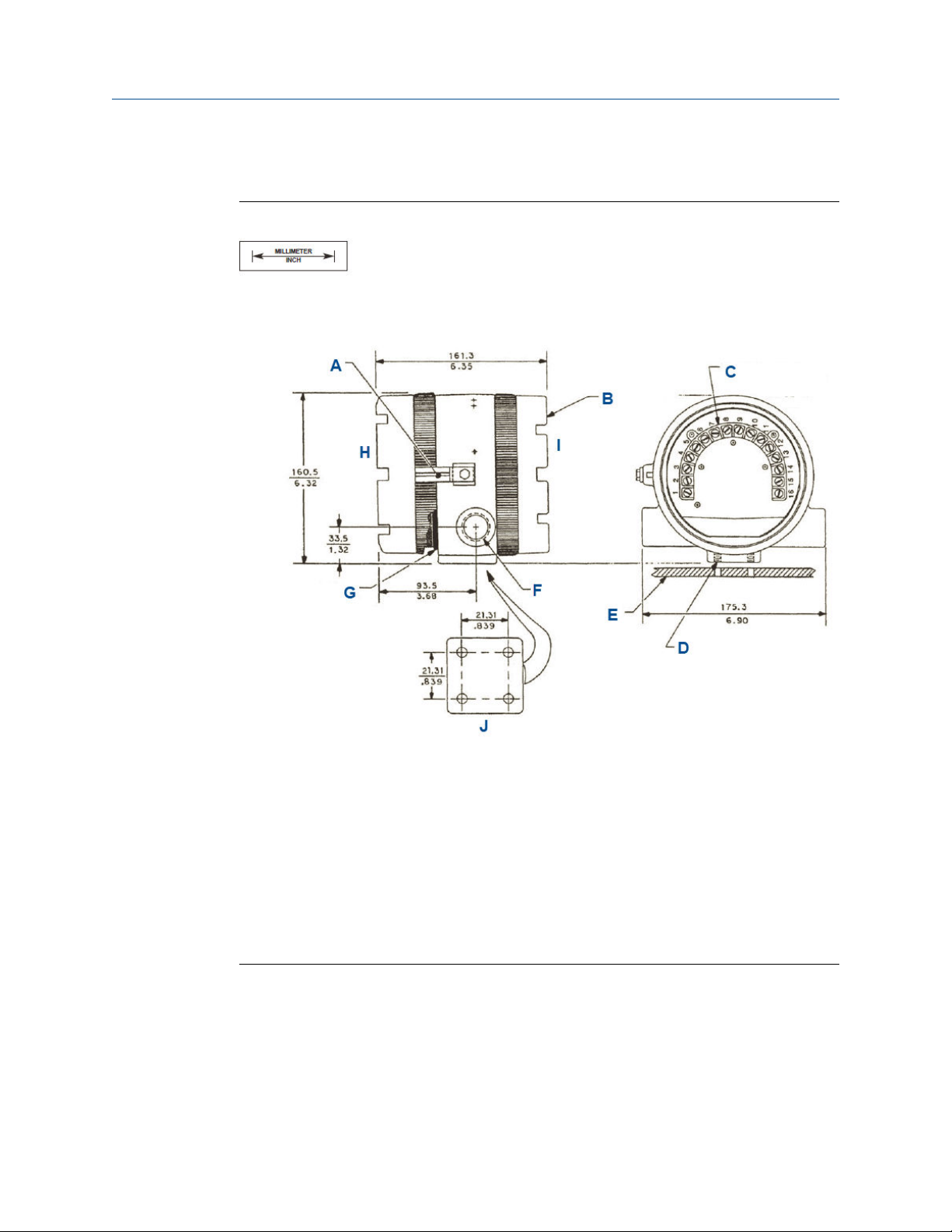
3.4 Mount on a flat surface
Figure 3-1: Mounting Transmitter on a Flat Surface
A. Cover lock
B. Threaded cap (two places)
C. Terminal block (TB). Terminal end cap omitted for clarity this view.
D. ¼-in. - 20 threads (four places)
E. Surface plate (by others)
F. O-ring (two places)
G. Circuit end
H. Terminal end
I. Flat surface mounting pad hole pattern
Reference Manual 21
Install
October 2019 00809-0100-3581
Reference Manual
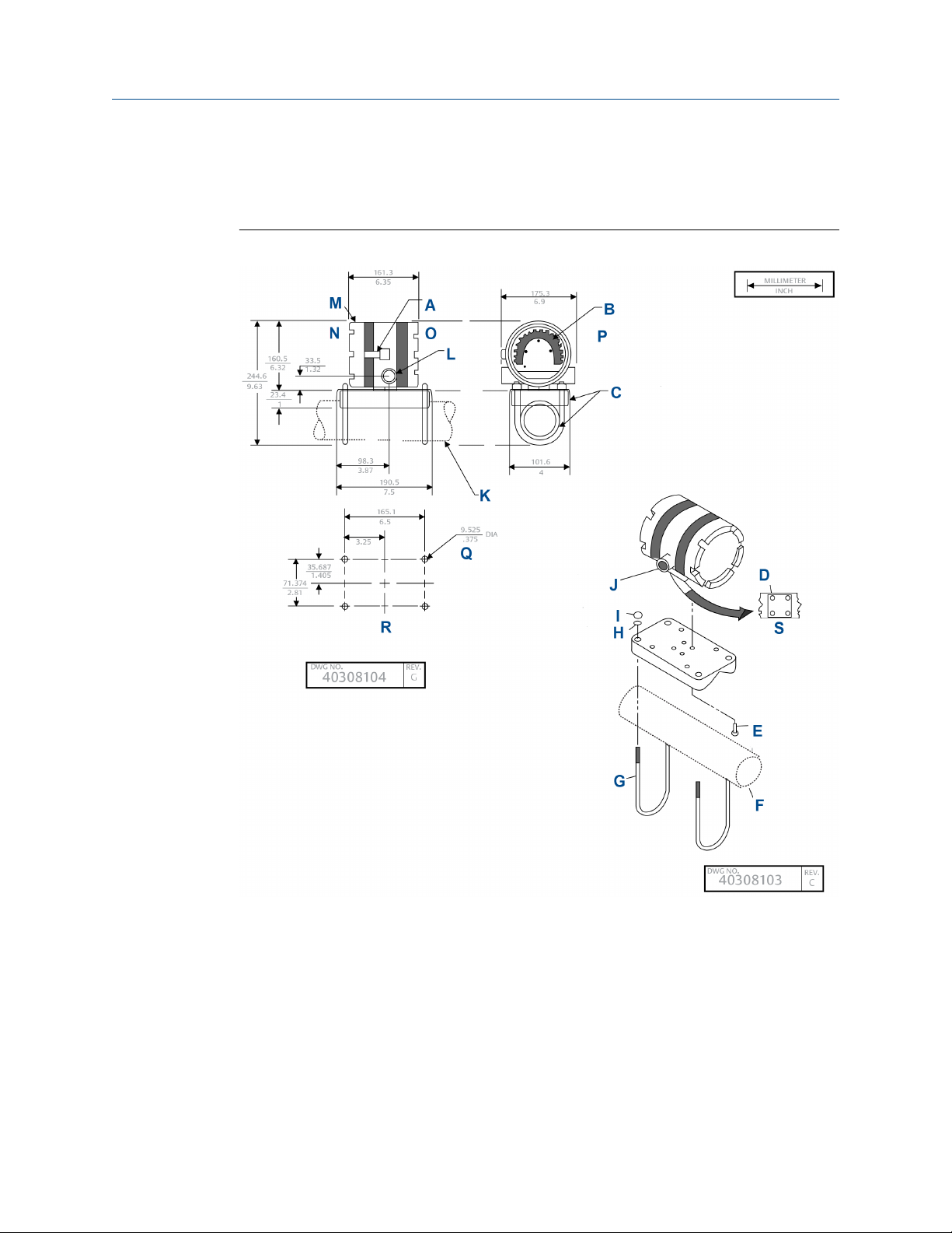
3.5 Mount on a pipe
Use pipe mounting kit (23820-00 or 23820-01).
Figure 3-2: Mounting Transmitter on a Pipe
A. Over look
B. Terminal block
C. Kit, 2-in. pipe/wall mounting bracket
Order PN2002577 as a separate item.
D. ½ - 20 threads
E. ¼ - 20 screw
Screws furnished with mounting kit only. Not furnished with transmitter.
F. 1½-in. to 2-in. pipe (customer furnished)
G. U-bolt
22 Rosemount 5081

Reference Manual Install
00809-0100-3581 October 2019
H. 5/16 washer
I. 6/18 - 18 nut
J. ¾ - 14 FNPT (two places)
K. 2-in. pipe supplied by customer
L. ¾ - 14 NPT (two places)
M. Threaded cap, two places
N. Circuit end
O. Terminal end
P. Terminal end cap omitted for clarity this view
Q. Four mounting holes
R. Bottom view
Reference Manual 23

Install Reference Manual
October 2019 00809-0100-3581
24 Rosemount 5081
Reference Manual
00809-0100-3581 October 2019
Wire
4 Wire
4.1 Wiring overview
To find wiring diagrams for specific sensors, check the wiring sections of the reference
manuals for those particular sensors.
4.2 Power supply/current loop
4.2.1 Power supply overview
The tables below display the minimum and maximum voltages needed to operate the
transmitter.
Minimum supply voltage at the transmitter
terminals
Minimum power supply for load resister 250 Ohms
Maximum power supply voltage 42.0 Vdc
Maximum power supply voltage for intrinsically
safe installations
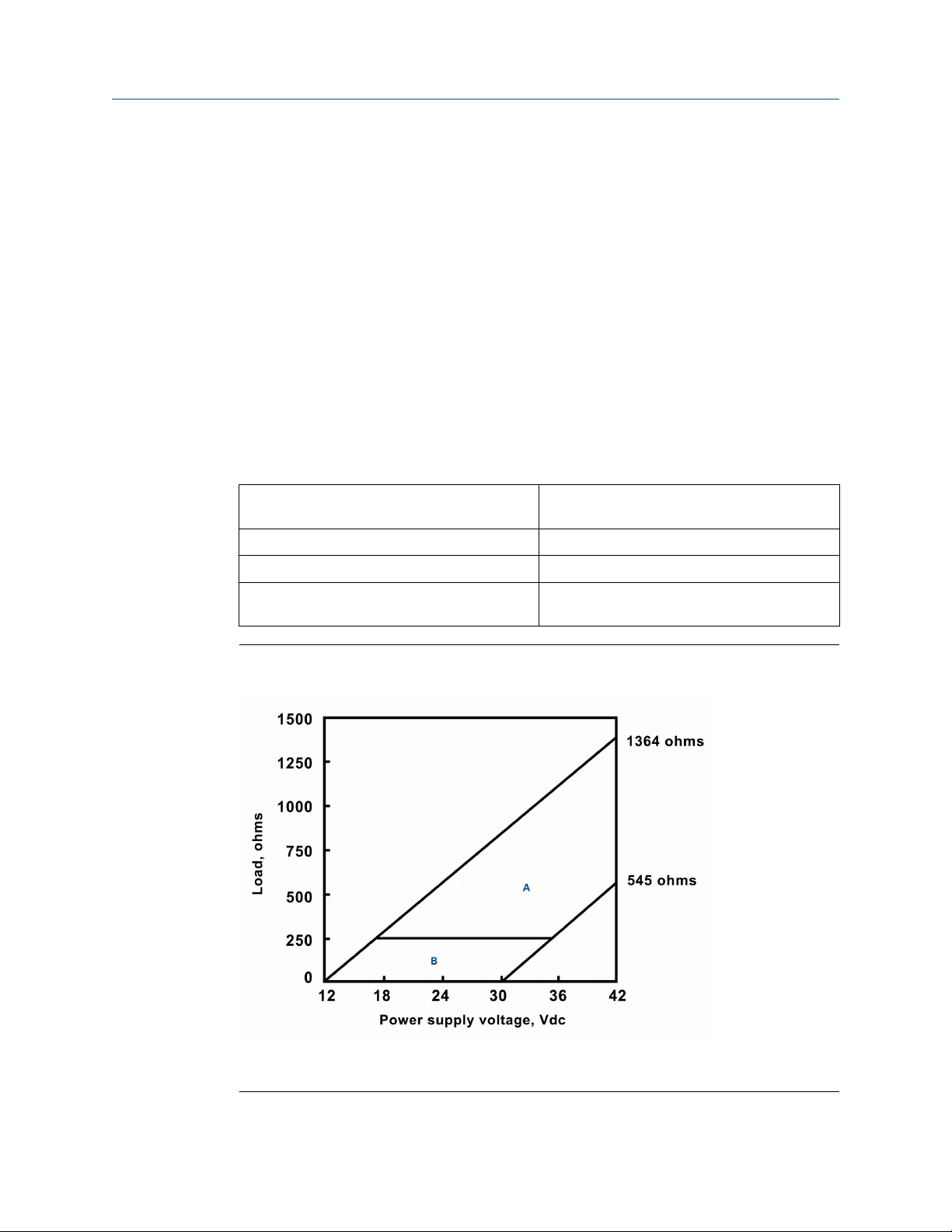
Figure 4-1: Power Supply Voltage for HART® or without HART Communication
Configurations
12.0 Vdc
30.0 Vdc
A. With HART communication
B. Without HART communication
Reference Manual 25

Wire Reference Manual
October 2019 00809-0100-3581
Table 4-1: Values from Graph
Upper line Power supply voltage needed to provide 12 Vdc
at the transmitter terminals for a 22 mA current
Lower line Power supply voltage needed to provide 30 Vdc
for a 22 mA current
Maximum current About 24 mA
Minimum load for digital communications 250 Ohms
Minimum power supply voltage to supply the
12.0 Vdc lift off voltage at the transmitter
17.5 Vdc
4.2.2 Wire to HART® or FOUNDATION™ Fieldbus communication protocol
Procedure
1. Run the power/signal wiring through the opening nearest terminals 15 and 16.
2. Use shielded cable and ground the shield to the power supply.
3. To ground the transmitter, attach the shield to the grounding screw on the inside of
the transmitter case.
You can also use a third wire to connect the transmitter to earth ground.
Note
For optimum EMI/RFI immunity, shield the power supply and enclose it in an earth
ground metal conduit. Do not run power supply/signal wiring in the same conduit
or cable tray with AC power lines or with relay actuated signal cables. Keep power
supply/signal wiring at least 6 ft. (2 m) away from heavy electrical equipment. An
additional 0-1 mA current loop is available between TB-14 and TB-15. A 1 mA
current in this loop signifies a sensor fault. See Figure 4-2 for wiring instructions. See
Diagnostics and troubleshooting for more information about sensor faults.
26 Rosemount 5081
Reference Manual Wire
00809-0100-3581 October 2019
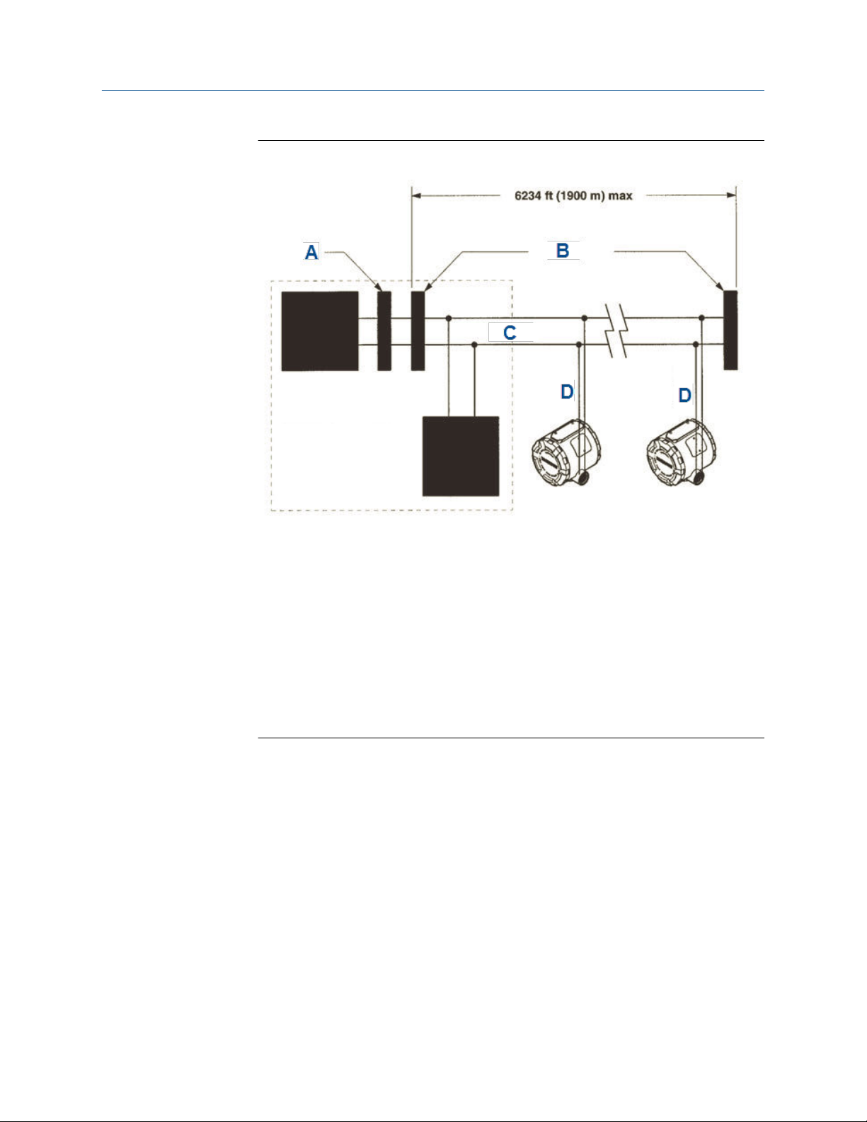
Figure 4-2: General Wiring Architecture
A. Filter
B. Terminators
C. Trunk
D. Spur
The power supply, filter, first terminator, and configuration device are typically
located in the control room.
Reference Manual 27

Wire Reference Manual
October 2019 00809-0100-3581
28 Rosemount 5081
Reference Manual Display and operate
00809-0100-3581 October 2019
5 Display and operate
5.1 User interface and main display
The following are examples of the main (process) display screen (Figure 5-1) and the
program display screen (Figure 5-2).
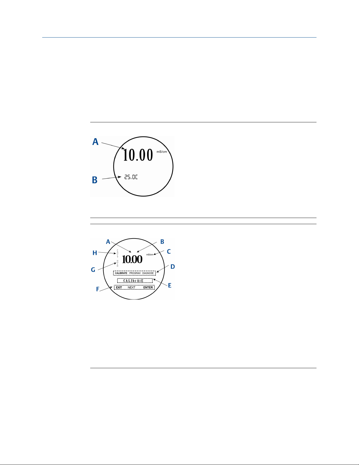
Figure 5-1: Main Display Screen
A. Conductivity value
B. Temperature in °C or °F
Figure 5-2: Program Display Screen
A. Indicates HART® or FOUNDATION™ Fieldbus digital communiciations
B. Conductivity value
C. Units of display
D. Active menu: CALIBRATE, PROGRAM, or DIAGNOSE
E. Sub-menus, prompts, and diagnostic messages appear here.
F. Available commands for sub-menus, prompts, or diagnostic messages
G. Appears when transmitter is in hold
H. Appears when a disabling condition has occurred
Reference Manual 29
Display and operate Reference Manual
October 2019 00809-0100-3581
5.2 Infrared remote control (IRC)
Use the IRC to read diagnostics messages, calibrate connected sensors, and program the
transmitter. Hold the IRC within 6 ft. (1.8 m) of the transmitter and less than 15 degrees
from the horizontal of the display window.
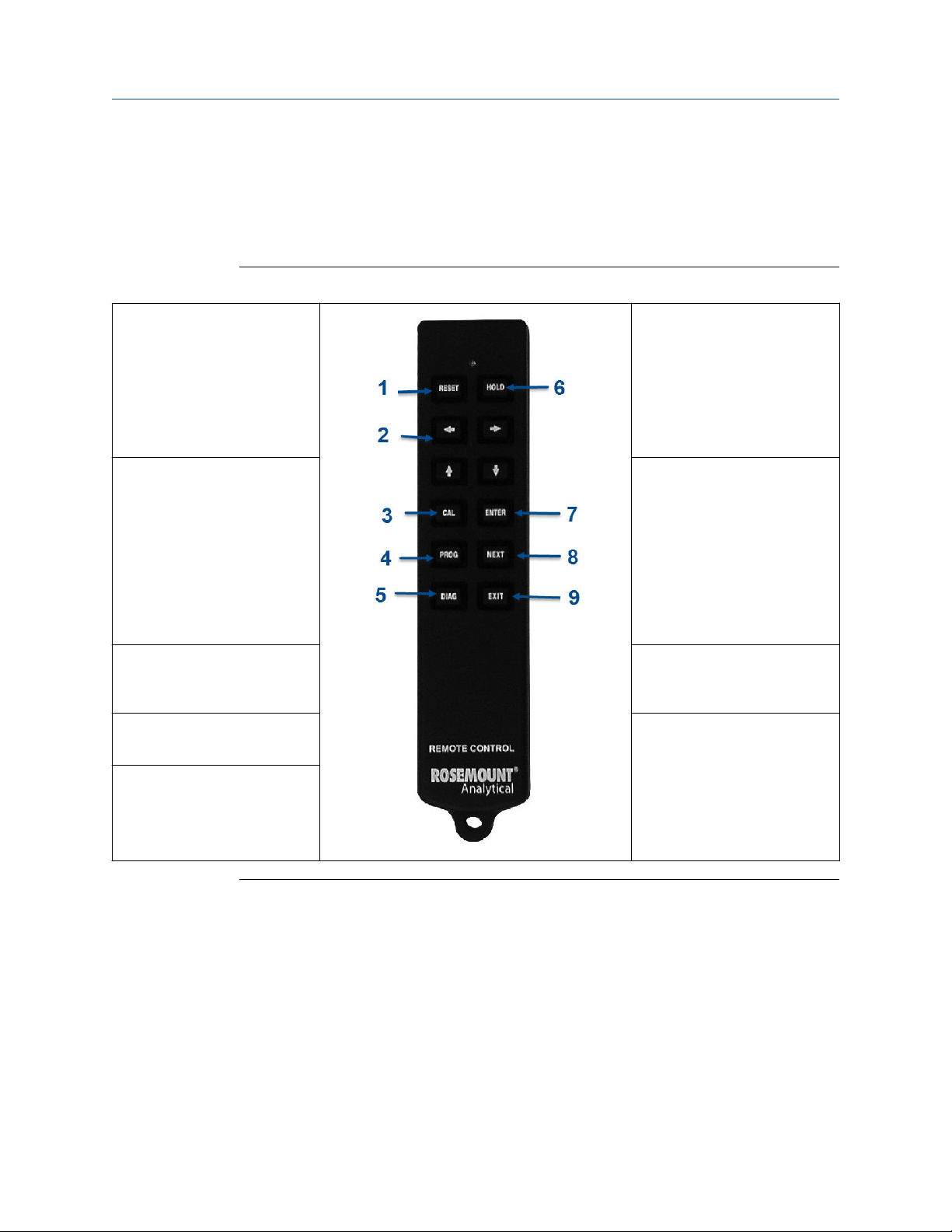
Figure 5-3: Infrared Remote Control (IRC) Functions
1. RESET
• End current operation and
return to the main display.
• Changes are not saved.
• Does not return the
transmitter to factory default
settings.
2. Editing (arrow) keys
• Change values of a flashing
display.
• Left and right arrows move
the cursor by one digit.
• Up and down arrows increase
or decrease the values and
navigate through the display
options.
3. CAL
• Access to Calibration menu.
4. PROG
• Access to Program menu.
5. DIAG
• Access to diagnostics.
6. HOLD
• Access to turn hold readings
on or off.
7. ENTER
• Advance to the next prompt.
• Store selected item.
• Store value in memory.
8. NEXT
• Advance to the next sub-
menu.
9. EXIT
• End current operation.
• Return to the first prompt in
the present sub-menu.
• Changes are not saved.
Guidelines for using IRC
• Do not use harsh chemicals or abrasive brushes when cleaning the remote control.
• If the green LED does not light when you press a key, the issue is probably a weak
battery. To restore operation, remove four screws to access and replace the two
batteries. Observe the two warning messages posted at the rear of the remote control.
• Requires two 1.5 V AAA batteries. If used in hazardous areas, replacement batteries
must be Energizer E92/EN92 or Duracell MN2400/PC2400.
• All functions for remote control PN 24479-00 are the same as those for the previous
remote control, PN 23572-00.
30 Rosemount 5081
 Loading...