

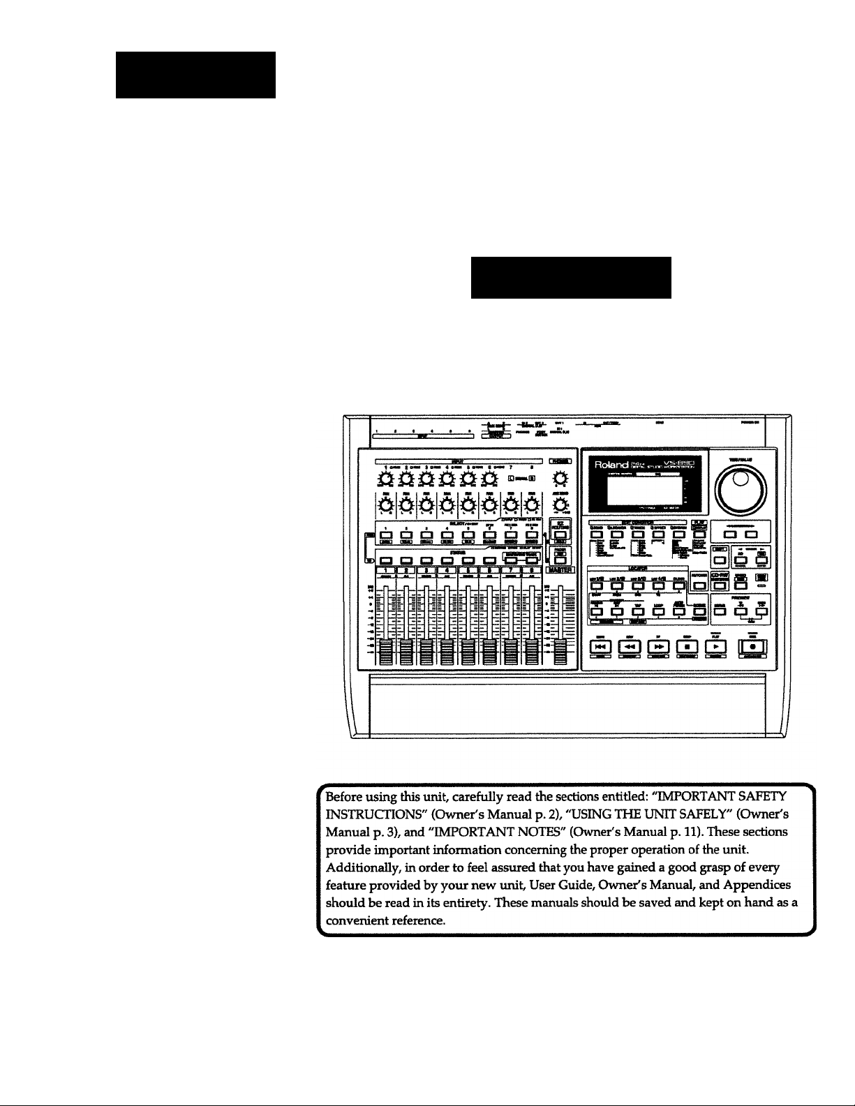
Page 1
Roland
STUDIO WORKS WON
Appendices
Copyright ©2000 ROLAND CORPORATION
All rights reserved. No part of this publication may be reproduced in any form without the
written permission of ROLAND CORPORATION.
Roland Web Site: http:/ /www.roland.co.jp/
Roland US Web Site: http: / / www.rolandus.com/
Page 2

Contents
I
J
Contents.........................................................................................................2
About MIDI....................................................................................................3
About SCSI.....................................................................................................4
Troubleshooting............................................................................................5
Error Messages.............................................................................................9
Glossary.......................................................................................................12
Special Key Operations..............................................................................14
Parameter List............................................................................................. 16
Preset Patch List.........................................................................................20
Aigorithm List..............................................................................................25
MIDI Implementation...................................................................................81
Mixer Section Block Diagram...................................................................127
Track Sheet................................................................................................129
Specifications............................................................................................130
Index...........................................................................................................132
Page 3

About MIDI
This section explains the basic concepts of MIDI, and ho\v the
VS-890 handles MIDI messages.
What is MIDI
МЮ1 stands for Musical Instrument Digital Interface. It is a
worldwide standard that allows electronic musical
instruments and p>ersonal computer to exchange musical
performance data and messages such as sound selections.
Any MIDI-compatible device can transmit musical data (as
appropriate for the type of device) to any other МГО1compatible device, regardless of its manufacturer or model
type.
MIDI connectors
МГО1 messages (the data handled by MIDI) are transmitted
and received using the following three types of connectors.
On the VS-890, MIDI OUT and МГО1 THRU are handled by a
single connector, which can be switched to act as the desired
connector. (Owner's Manual p. 161)
MIDI IN; This receives МГО1 messages from external
МГО1 devices.
MIDI OUT: This transmits MIDI messages from the
VS-890.
MIDI THRU: This re-transmits all МГО1 messages that were
received at MIDI IN, without modifying them.
MIDI channels
МГО1 is able to send information over a single МГО1 cable
independently to two or more МГО1 devices. This is made
possible by the concept of MIDI channels. You can think of
МГО1 channels as being somewhat similar in function to the
channels on a television. By changing the channel of a TV set,
you can view a variety of programs being transmitted by
different broadcast stations. This is because data is received
only from the transmitter whose channel is selected on the
receiver.
In the same way, a МГО1 device whose receive channel is set
to "1" will receive only the data being transmitted by another
MIDI device whose transmit channel is also set to "1."
MIDI messages
The VS-890 uses the following typ>es of MIDI message.
these messages are used when you use a MIDI sound source
to play the metronome sound.
Program Change messages:
These messages are for the purpose of selecting sounds, and
contain a program number of 1-128, The VS-890 uses these
messages to select scenes and effects. (Owner's Manual p. 172)
Control Change messages:
In general, these messages are used to transmit information
such as vibrato, hold, and volume etc., that makes a
performance more expressive. The various functions are
differentiated by a controller number from 0-127, and the
controller number is defined for each function. The functions
that can be controlled on any given device will depend on
that device.
On the VS-890, these messages are used in a completely
different way than on most instruments; they are used to
control mixer parameters.
Exclusive messages:
Unlike note messages and control change messages,
exclusive messages are used to transmit settings that are
unique to,a particular device. On the VS-890, exclusive
messages can be used to control mixer parameters (in the
same way as control change messages). Normally, control
change messages are easier to handle, so they should be used
rather than exclusive messages. Exclusive messages intended
for different units are distinguished by their Device ID,
rather than by MIDI channel. When exclusive messages are
to be transmitted or received, you must set the Device ID of
both units to a matching setting.
MIDI implementation chart
MIDI allows a variety of electronic musical instruments to
communicate with each other. However it is not necessarily
the case that all devices will be able to communicate using all
types of MIDI message. They can only communicate using
those types of MIDI message that they have in common.
Each owner's manual for a MIDI device includes a MIDI
Implementation Chart. This chart shows you at a glance the
types of MIDI message that can be transmitted and received.
By comparing the implementation charts of two devices, you
will be able to see the types of message with which they will
be able to communicate.
Note messages:
These messages are used to play notes. On a keyboard, these
message transmit the key (note number) that was pressed,
and how strongly it was pressed (velodty). On the VS-890,
Page 4

About SCSI
SCSI stands for Small Computer System Interface. It is a
data transfer standard that allows large amounts of data to
be sent and received. The VS-890 comes prepared with a
SCSI connectors allowing you to connect external SCSI
devices such as hard disks and Zip drives. This section
describes the procedures and precautions taken when using
these devices.
Disk drives are precision devices. If they are connected or
used incorrectly, not only may they fail to operate correctly,
but the data on the disk can be lost or, in the worst case, the
disk drive itself may be damaged. Please be sure to read the
manual for your disk drive.
A disk drive being used for the first time with the VS-890
must be initialized by the VS-890 (Owner's Manual p. 134).
When a disk drive is initialized, all data on that disk drive is
lost. Before using a disk drive that has been used by another
device, make sure that it is all right to erase the data.
About Connections
Up to 7 disk drives can be connected to the SCSI connector of
the VS-890. Use SCSI cable to connect the disk drives,
connecting as shown below. SCSI connectors are not
distinguished by input and output ends, so you may attach
either end of the cable to the devices. Devices connected in
this fashion are referred to as a SCSI chain or daisy chain.
About Terminators
To protect against return noise, the device at each end of a
SCSI chain must have a terminating resistance. This is
referred to as a terminator. Since the VS-890 is one end of the
SCSI chaia its internal terminator is normally in effect.
Connect a terminator only to the last externa! drive in the
chain. There are two types of terminators, those that can be
switched on and off (internal) and those that are attached
using SCSI connections (externally attached). Select the
method appropriate for the disk drive you are using.
• Your disk drive may feature a terminator switch that is
normally left in the "On" position (i.e., the terminator is
usually in effect). Use this type of device as the last piece
in a daisy chain.
• Do not use double terminators. For example, don't attach
an externa! terminator to a disk drive that already has
and internal terminator.
Active Terminators
If you are using an external terminator, we recommend that
you make it an active terminator. In this case, if you are using
a disk drive that allows you to turn the power to the
terminator on and off, be sure to turn this power on. For
details on attaching an active terminator, refer to the owner's
manual ftrr your disk drive.
Active Terminator (p. 12), Terminator Power (p. 13)
VS-B90
The VS-890 features a DB-25 type connector (female).
After checking your disk drive to see what kind of SCSI
connector it uses, connect it with the appropriate cable.
Keep SCSI cables as short as possible, and use only
cables which have an impedance that is compatible with
the SCSI standard (llOQ + /-10%), and that are
completely shield.
Do not allow the total length of all SCSI cables
connecting the chain of disk drives to exceed 6.5 meters.
Do not connect or disconnect SCSI cables when the
power of any device is turned on.
Disk Drivel
(Zip Drive, etc)
Disk DriveZ
(Zip Drive, etc)
Disk Drive?
(CD-RW Drive, etc)
About SCSI ID Numbers
Each disk drive is distinguished by its SCSI ID number (0-7).
ITiis means that when two or more disk drives are connected,
you must make settings so that the SCSI ID numbers of the
disk drives do not conflict (coincide). If the SCSI ID numbers
conflict, the VS-890 will not be able to correctly recognize the
disk drives.
With the factory settings, the VS-890 is set to SCSI ID number
7. Set the disk drives you are connected to ID numbers other
than 7.
Page 5

Troubleshooting
When the VS-890 does not perform the way you expect,
check the following points before you suspect a malfunction.
If this does not re.solve the problem, contact servicing by
your dealer or qualified Roland Service Center.
Recording and Playback
No Sound
• The power of the VS-890 and the connected devices is
not turned on.
• The audio cables are not connected correctly.
• The audio cables are broken.
• The volume is turned down on the connected mixer or
amp.
• Each Levels of the VS-890 is turned down.
Channel fader
Master fader
PHONES knob
• The output jacks which are connected are different than
tlie output jacks selected in the master section of the
mixer (Owner's Manual p. 183).
• Short phrases less than 0.5 seconds cannot be played
back.
• The volume level of the instrument connected to
the VS-890 is too low.
—> Could you be using a connection cable that contains
a resistor? Use a connection cable that does not
contain a resistor.
• 1 can't record or play back, even when I press [PLAY].
-> Does the he PLAY indicator just blink green? When
the SYNC MODE fields in the display indicates
"EXT'," the VS-890 is receiving MTC receive standby
messages from the external MIDI device. Operate
the external MIDI device or press
-> When "PoweЮFF/RESTART" appears in the
display it means that the shutdown procedure is
being performed. Hold down [SHIFT] and press
[PLAY (RESTART)]. This restarts the VS-890.
[STOP].
A specific channels does not sound
• The input mixer or the track mixer has not selected
correctly.
• The volume level of the channel is turned down.
-> When switching between the input mixer and track
mixer, recalling Scenes, using Auto Mix, or in other
such situation, the actual volume levels may not
match the position of the faders. In such cases, bring
the faders up or down to match the settings.
• The track is off (the STATUS indicator is off).
• The Mix Send Switch is set to "Off."
• The Solo or Mute function (Owner's Manual p. 174) is
being used.
• "Cntrl Local" is set to "Off."
-> In this case, fader movements have no effect.
Cannot record
• The recording track has not been selected (the STATUS
indicator is not blinking red).
• Recording source tracks, playback tracks, or effects have
not been assigned.
• The disk drive has insufficient capacity.
• The song has an insufficient number of events (Owner's
Manual p. 24).
• The number of tracks which can be simultaneously
recorded will decrease.
When the Sample Rate is selected to "48 kHz," up to
6 tracks can be recorded simultaneously.
When the Vari Pitch is selected to "On," up to 4
tracks can be recorded simultaneously.
Cannot record digitally
• The QI) player's digital connection is not accepted
(Owner's Manual p. 67).
• The master clock is set to "INT" (Chvner's Manual p.
68).
• The DIGITAL IN connector (optical or coaxial) was not
properly selected.
Continued..
Page 6

Troubleshooting
• The sampling rate of the recording destination song is
different than the sampling rate of the digital audio
device.
-> Match the sample rate setting of the digital audio
device to the setting of the song. If it is not possible
to change the sample rate of the digital audio device,
create a new song with that sample rate.
• The digital signal is not being transmitted from the
digital audio device.
-> Some digital audio devices do not output a digital
signal unless they are in play mode. If this is the
case, put your digital audio device in standby
(pause) mode before putting the VS-890 into record
mode.
• The digital signal format is different.
Some digital audio devices may use a special digital
signal format. Please connect to a digital audio
device that is compatible with S/ P DIF.
Noise and distortion appear in the recorded sound
• Input sensitivity settings are incorrect.
If input sensitivity settings are too high, the
recorded sound will be distorted. Conversely, if they
are too low, the recorded sound will be obscured by
noise. Adjust the INPUT knobs so that the level
meters move at as high a level as possible, within the
range of -12 dB to 0 dB.
• The equalizer is being used with the input mixer.
Some equalizer settings may cause the sound to
distort even if the PEAK indicator does not light.
Readjust the equalizer.
• "ATT" (Attenuator) setting is incorrect. (Owner's
Manual p. 182)
-» If noise or distortion occurred as a result of track
bouncing, the track output levels were too high.
The playback pitch is strange
• The Vari-Pitch function is turned on.
• The time compression/expansion function is being used
(Owner's Manual p. 88).
Disk drive problems
The internal hard disk is not being
recognized
• The hard disk has not been installed correctly (User
Guide p. 5).
• "IDE Drive" is set to "Off" (Owner's Manual p. 194).
• The "Partition" settings are not right (Owner's Manual
p. 134).
When a high-capadty hard disk is installed in the
VS-890, we recommend setting the partition size to
"1000MB."
• Although the Track Erase operation is finished, the
available recording time does not increased.
-» The audio data is erased by Track Cut, Track Erase
or Phrase Delete etc., the data that is no longer
played back is not actually erased from the hard
disk. If you wish to increase the available recording
time, please read "If "Disk Full!" appears in the
di.splay (Song Optimize)" (Owner's Manual p. 122).
The Zip drive is not recognized
• The Zip drive is not connected correctly.
• The same device ID number is assigned to two or more
SCSI devices (Zip drives, CD-RW drives, etc.).
• The Zip drive has not been initialized (Owner's Manual
p. 134).
• No Zip disk is inserted in the drive.
When switching Zip disks, be sure to select the
newly inserted disk as the current drive.
• An archives copy Zip disk is inserted.
-> Playable copies £ind archives copies have different
disk formats. Take precautions such as sticking
labels on disks saved as archive type data disks to
distinguish the from other disks.
• The VS-890 song data saved on Zip disks cannot use the
computer's internal Zip drive.
-* The VS-890 song data format is particular to the VS-
890. Other than the other VS-series data ported
(Song Export) to the VS-890, the data cannot be
handled by other devices.
• Initialization is cancelled, with error messages such as
"Medium Error," "Not 512 bytes/sector," "Function
Failed!" or other messages appearing in the display
The Zip disk may scratched or be otherwise
damaged. Try another (new) disk to check whether
or not the same condition reappears.
-> The Zip drive may be broken. Connect the Zip drive
to a device other than the VS-890 (e.g., your
computer) to see if the drive can initialize disks, read
files, and perform other operations normally.
Page 7

Troubleshooting
Internal Effects
Effects cannot be used
• You are attempting to select the algorithm for Reverb,
Gated Reverb, Vocoder 2, Voice Transformer or
Mastering Tool Kit with FX2.
• You are already attempting to select the algorithm for
Vocoder 2, Voice Transformer or Mastering Tool Kit
with FXl (Owner's Manual p. 119).
• I'd like to change the order of an effect algorithm.
The connection orders cannot be altered. They can
only be turned on or off. For more detailed
information on what goes on with the algorithm
orders, please refer to the "Algorithm List" (p. 25).
CD-RW Drive Problems
I made an audio CD on the CD-R/RW
drive, but it doesn't play on a
consumer CD player.
• The finalized process was not carried out. When making
audio CDs, set "Finalize" to "On" or "OnlyFin."
(Owner's Manual p. 143).
• Audio CD's created using a CD-RW disc cannot be
played on a conventional CD player. Please use a CD-R
disc.
The CD-R drive is not being recognized
• The CD-RW drive is not connected correctly.
• The same device ID number is assigned to two or more
SCSI devices (Zip drives, CD-RW drives, etc.).
• No CD-R/RW disc is iaserted in the drive.
• A CD-RW drive that is not designated by Roland.
Cannot write to CD-R discs
• The song's sample rate is set to something other than
44.1 kHz (Owner's Manual p. 143).
• No IDE hard disk is installed.
• The internal IDE hard disk does not have sufficient free
disk space.
• The CD-R disc does not have sufficient free space.
• You are trying to write to a commercial CD software
disc.
• You are trying to write to a CD-R disc that has been
finalized.
MIDI Devices Problems
With the VS-890 as master, the MIDI
sequencer does not respond to
commands
• The МГО1 cable is not connected correctly.
• The MIDI cable is broken.
• The МГО1 Thru switch is not set to "Out" (Owner's
Manual p. 160).
• "Sync Gen." (the sync generator) is not set to the
appropriate synchronization method (MTC, MIDI Clock,
Sync Track) (Owner's Manual p. 160).
• The SYNC MODE fields in the display indicates "EXT."
("Sync Source" is set to "EXT").
• The two devices are not set to the same t)?pe of MTC
(during MTC synchronization).
• The MIDI clock data has not been recorded on the sync
track (if you arc using the sync track for
synchronization).
• The settings of the MIDI sequencer are not correct.
• The MIDI sequencer is not ready to playback.
• The VS-890 mixer level and pan settings changed by
themselves.
-> The VS-890 receives Control Change messages as
well as System Exclusive messages. When set to
receive Control Change messages transmitted by a
MIDI sequencer, the VS-890's mixer can be
controlled by external devices. When this feature is
not needed, set the "Control Type" to "Off."
When synchronizing using a MIDI
sequencer as the master, the VS-890
does not respond to the sequencer
messages
• The MIDI cable is not connected correctly.
• The MIDI cable is broken.
• You are trying to synchronize using the MIDI clock.
The VS-890 cannot be run in slave mode using a
method other than MTC.
• The SYNC MODE fields in the display indicates "INT."
("Sync Source" is set to "INT").
• The two devices are not set to the same typ)e of MTC
(during ^ГГC synchronization).
• The settings of the MIDI sequencer are not correct.
• The VS-890 is not in playback standby mode (with the
PLAY indicator blinking).
• MFC reception is in poor condition.
-> Setting the Sync Error Level to "5" or higher may
improve conditions.
Page 8

Troubleshooting
With о vídeo device os the master, the VS-890 does not respond
• The cable connected to the L-connector, the SYSTEM E
connector or the MIDI cable is not properly connected.
• 1’he MIDI cable is broken.
• The SYNC MODE in the display indicates "EXT."
("Sync Source" is set to "INT").
• "Sy.sEX.Rx." (System Exclusive Receive Switch) is not set
to "On."
• "MMC" (MMC mode) is not set to "SLAVE."
• The MTC frame rate of the video device differs from that
of the S1-80SP (Roland Video MIDI Sync Interface), or the
video and the VS-890 are not set to the same type of
MTC.
• MTC reception is in poor condition.
Setting the Sync Error Level to "5" or higher may
improve conditions.
Other problems
Data on the disk drive was not saved
properly
• The VS-890's power was turned off without performing
the shutdown process.
• The power was turned off while the disk drive was
operating.
• A strong shock was applied to the disk drive.
• The disk drive or SCSI cable was connected or
disconnected while the power was still turned on.
Reinitialize the disk drive (and also execute physical
formatting) (Owner's Manual p. 134). Also, we
recommend that you execute Surface Scan as well
(Owner's Manual p. 135).
8
Page 9

Error Messages
Aborted Command!
Illegal Request!
This disk drive cannot be used by the VS-890.
Already Selected
The currently selected disk drive was selected. If you wish to
switch to another disk drive, re-select the disk drive.
Arbitration Failed!
Busy Status!
Check Condition!
Status Error!
Normal communication with the disk drive could not be
accomplished. Make sure that the disk drive is connected
correctly.
Blank Disc
You have tried to run the CD player function using a disc
that has no performance data on it. Insert a commercial CD
or CD-R/RW with material already recorded on it.
Can't Communicate!
Drive Time Out!
Message Error!
Phase Mismatch!
Undefined Sense!
Drive Unknov/n Error!
There is a problem with the connections to the disk drive.
Make sure that the disk drive is connected correctly.
Can't REC CD !
With the factory setting, digital connections cannot be made
with a CD player. Please read 'To Recording Digital Signals"
(User Guide p. 36).
Can't Recover
The drive check Recover procedure could not be executed
because there was insufficient free space on the disk. Delete
unneeded songs. Alternatively, perform the Song Optimize
procedure.
Can't Set Marker
No more than two track number mark points can be set
within a four-second interval.
Complete
The operation ended normally.
Change Int CLK ?
No digital signal is being received at the DIGITAL IN
connector. Select whether or not to switch the sample rate
reference dock to the internal clock. Pressing [ENT/YES]
switches the VS-890 to the internal clock. After checking to
make sure that all digital devices are properly connected and
those sample rates for all devices match, carry out the
operation once more.
Digital in Lock
The sample rate reference dock is set to the digital signal
coming from the DIGPrAL IN connedor. You can record
using the digital connection.
Digital In Unlock
The digital signal is not being input through the DIGITAL IN
connector, or the sample rate set for the song and the sample
rate of the digital device conneded to the DIGITAL IN
connedor are different. In this state, you cannot record using
the digital connedion.
The sample rate spedficd for the song is different than the
sample rate of the digital device connected to the DIGITAL
IN connedor. Press
both devices to match.
[ENT/YES], and set the sample rates of
Disk Memory Full!
There is insufficient free area on the disk. Erase unneeded
data. Or, seled a different disk drive. The maximum number
of songs that can be recorded on one partition (200) has been
exceeded. Delete unneeded songs. Or, seled a different disk
drive.
Drive Busy!
If this message appears when you first begin using a disk
drive with the VS-8W, the disk drive is not fast enough.
When using this disk, create a new song with a lower sample
rate or recording mode, and record using this song.
If this message appears after you have been using the disk
drive with the VS-890, the data on the disk drive has become
fragmented, causing delays in reading and writing data.
Either use the track boundng operation to re-record playback
data to another track, or use the optimize operation. If the
same message appears even after these measures have been
taken, copy the song data to another disk drive and initialize
the disk drive that produced the problem.
Event Memory Full!
The VS-890 has used up all the events that can be handled by
one song. Delete unneeded auto mix data. Alternatively,
perform the Song Optimize operation.
Page 10

Error Messages
Finalized CD !
This message appears when an attempt is made to write to a
commercial CD or a finalized CD-R disc. Replace the disc
with a blank disc or one that has not been finalized.
Illegal Track Pair!
You are trying to Track Edit (Copy, Move, or Exchange etc.)
between a V-track that has been recorded with "CDR"
(Recording Mode or CDRRecMode) and a normcd
V-track. Please select the source and the destination V-tracks
again.
Function Failed
Processing was halted due to insufficient memory or due to
an error which occurred in the disk drive itself. Check
connections and reliability.
Hardware Error!
There is a problem with the disk drive. Contact the
manufacturer or dealer of the disk drive.
illegal Track!
You are trying to Phase New between a V-track (take) that
has been recorded with "CDR" (Recording Mode or
CDRRecMode) and a normal V-track (take). Please select the
source and the destination V-tracks again.
Lack of CD-R Memory!
There is insufficient free space to write the songs to the CDR/RWdisc.
Lack of EVENT !!
You have tried to UNDO or REDO when the remaining
number of Event is less than 200. You cannot continue the
current operation.
Lack of IDE Memory!
There is insufficient free space on the internal IDE hard disk
to make the image data file.
MARKER Memory Full!
The VS-890 has used up all Marker Memory (1000 Markers)
that can be handled by one song. Delete unneeded Marker.
Medium Error!
There is a problem with the disk drive media. This disk
cannot be used by the VS-890. In some case's recovery can be
achieved by executing Drive Check.
No CD-R Drive !
Either no CD recorder (CD-R/RW drive) is connected, or the
power is not turned on.
No Data to Write
The track that you have selected to write to CD-R/RW disc
contains no song data.
No Disc
There is no di.sc in the Roland CD recorder (CD-R/RW
drive). Please insert a disc.
No Drive Ready
No disk drive is connected. Or, an internal hard disk is not
installed. Make sure that the disk drive is connected
correctly.
No IDE Drive !
The unit has no IDE-type disk drive. Install an internal hard
disk.
Not 44.1 k Song !
The sample rate of the song is not 44.1 kHz, so the data
cannot be written to the CD-R/RW disc.
Not 512byte/sector
The disk that you are using is not 512 bytes/sector. This disk
cannot be used by the VS-890.
Not Ready!
The disk drive is not ready. Wait a short time.
Obey Copyrights ?
This message asks if you agree to the terms and conditions
regarding the reproduction, broadcast, and sale of the
software. Please carefully read the License Agreement.
Please Insert CD-R Disc !
Either the Roland CD recorder (CD-R/RW drive) loading
tray is still open, there is no CD-R/RW disc loaded, or the
CD-R/RW drive is otherwise not ready. Insert CD-R/RW
disc.
Please Wait...
Operation is in progress. Please wait momentarily.
SCSI ID Error!
The SCSI ID numbers of two or more disk drives are
conflicting. Make settings so that the SCSI ID numbers do not
conflict.
SPC Not Available!
The SCSI components of the VS-890 have malfunctioned.
Contact servicing by your dealer or qualified Roland service
personnel.
10
Page 11

Song Protected!
Since Song Protect is ON, the operation cannot be executed.
TOC Read Error!
An error occurred in reading from the CD-R/RW disc. There
is a problem with the Roland QD recorder (CD-R/RW drive)
or the CD-R/RW disc.
Too Many Markers!
You have tried to set track, number mark points in excess of
the maximum (98) you can set for one CD.
Unformatted!
The disk drive has not been initialized by the VS-890.
Initialize the disk drive.
If this appears for a disk drive that has been initialized by the
VS-890, there is a problem with the connections to the disk
drive. Make sure that the disk drive is connected correctly.
User Aborted!
The procedure has canceled by pressing [EXiT/NO].
Error Messages
Write Another ?
Writing to the disc is complete. Select whether or not you
want to write the same data to a new disc. Press [YES] or
[NO].
Write Protected!
The disk drive is protected.
11
Page 12

Glossary
Active Terminator
A type of terniinator (a terminating resistance) place at each
end of a SCSI chain. A new addition to SCSI-2 specifications,
compared with ordinary terminators, it provides greater
operating stability for SCSI devices, thus improving signal
transmission performance.
CD-R
Short for Compact Disc Recordable. This is a system for
reading and writing discs in the seme format as that used for
CDs (CD-ROMs and music CDs). A specialized CD-R drive
allows one-time only writing of discs.
However, as long as the data has not been finalized and there
is sufficient capacity remaining on the disc, the CD-R drive
can be used for multiple additions to, and changes in the
material.
Sometimes they are referred to as "Write Once CD," "CDWrite Once," or something similar.
CD-RW
Short for Compact Disc Rewritable. This is a system
allowing creation of discs that can be read using the same
format as regular CDs (CD-ROMs and Music CDs). While
resembling the CD-R system in that it uses a special CD-RW
drive, these discs can be rewritten any number of times.
COSM
Stands for Composite Object Sound Modeling. This is "a
technology which combines multiple sound models to create
new sounds," which was first used on the Roland's VG-8 VGuitar System. For example, .sounds created on the VG-8 are
the result of a variety of sound models (elements) such as the
pickup, the body of the guitar, the guitar amp, mic, and
speaker etc.
Current Song
The song currently being recorded, played back, or edited is
referred to as the current song.
DAT
Short for Digital Audio Tape. This refers both to the system
of recording digitized sound to magnetic tape, as well as to
the tapes themselves. Besides digital audio signals, all song
information is recorded on the tape, including starts and
track data, information to allow or prevent copying, etc.
Formants
A formant is an important element which determine the
character of a vocal sound. It is a fixed overtone whose
location is determined by the size of the vocal chords.
Conventional pitch shifters modify the pitch in a way that
changes even the location of the formants (which by nature
do not change). For example when a conventional pitch
shifter raises the pitch, a "duck voice" is produced as if the
vocal chords had shrunk, and when the pitch is lowered a
"giant voice" is produced as if the vocal chords had
expanded.
The Voice Transformer modifies the basic pitch and the
formant separately, allowing a variety of voice characters to
be created.
Frame
Similar to the individual frames in a roll of movie film, the
numerous still pictures that are displayed in rapid succession
to create a moving video image are also known as "frames."
About thirty of these frames are shown each second. When
hard disk recorders, sequencers, and other such equipment
are synchronized with video, it is generally assumed that
there should be one frame every 1 / 30th of a second.
GPi
GPI stands for General Purpose Interface. This is a control
jack provided on professional and consumer video devices
such as video editors and title superimpoters. By connecting
this control jack to the foot sw'itch jack of the VS-890 and
setting die Foot Switch Assign to "GPI," the connected
device will be able to playback/stop the VS-890.
IDE
IDE stands for Integrated Device and Electronics. This is
the standard data transmission method used by the hard disk
drives of recent personal computers. The HDP88 series hard
disk drives (sold separately) that can be installed in the
VS-890 are IDE compatible.
MMC
MMC is an acronym for MIDI Machine Control. This is rule
that defines how MIDI system exclusive message can be used
to control multiple recording devices from a single device.
The VS-890 supports MMC. In addition to song playback,
stop and fast-forward, you can also select the tracks for
recording, etc.
Finalize
This is the operation that writes the TOC to a prepared audio
disc. Whereas additions and changes can be made to discs
that have not yet been finalized, such discs are not playable
on regular CD players.
12
MTC
MTC stands for MIDI Time Code. This is a group of
messages which are transmitted and received between МГО1
devices to synchronize their operation. Unlike MIDI Clock
messages, MTC specifies an absolute time. Like SMPTE time
code, MTC also supports a variety of frame rates. If you wish
to use MTC to synchronize the operation of two devices, both
devices must be set to the same frame rate.
Page 13

Glossary
NTSC Format
Color television format used in Japan, the United States, and
other countries. Tapes recorded in the NTSC format cannot
be played back on video decks utilizing the SECAM/PAL
formats.
R-BUS
Roland's digital communication specification developed to
allow audio and control data to be exchanged between
devices. Multi-channel audio signals, word clock, and MIDIcompatible operation data and synchronization signals can
be exchanged. A single R-BUS connector allows
simultaneous bi-directional transfer of eight channels of
digital audio data. The connector is a DB-25 type, and uses a
special cable for connections. It should NOT be connected to
other types of ports that use similar connectors!
The VS-890 is NOT provided the R-BUS connector.
Removable Disk Drives
Disk drives that have been able to remove the disk, such as a
Zip drive, arc referred to as the "removable disk drives."
RSS
RSS stands for Roland Sound System. This is an effect
which allows a sound source to be placed in threedimensional space when played back on a conventional
stereo system. The sound can be placed not only in front of
the listener, but also directly to the side, above, below, and
behind the listener.
S/P DIF
S/P DIF stands for Sony/Philips Digital Interface Format.
This is a specifications for transmitting and receiving stereo
digital audio signals between digital audio devices.
The VS-890 provides coaxial connectors which support S/P
DIF.
SCMS
SCMS stands for Serial Copy Management System. This is
a function that protects the rights of copyright holders by
prohibiting recording via a digital connection for more than
two generations. When digital connections are made
between digital recorders that implement this function,
SCMS data will be recorded along with the audio data.
Digital audio data which contains this SCMS data cannot
again be recorded via a digital connection.
SECAM Formaf's/PAL Formats
Color television formats used in Europe and other areas.
Tapes recorded in the SECAM or PAL formats cannot be
played back on video decks designed for the NTSC format.
Shutdown
In order to turn the power off safely, you must first make
sure that the performance has been saved to hard disk, and
that the hard disk heads are parked. This procedure is
referred to as Shutdown.
SMPTE time code
This is a signal format defined by the American organization
SMPTE (Society of Motion Picture and Television Engineers)
which is used to synchronize the operation of video or audio
devices. SMPTE specifies "hours:minutes:seconds;frames" to
indicate the address of each frame of a video image. For this
reason, there are a variety of frame rates.
Terminator Power
This refers to the power supplied to external type active
terminators.
TOC
Short for Table of Contents. This is the region on the CD-R
disc that handles information such as song times, end times,
sequence, and so on. Although the songs on a disc and their
playing time can be displayed when an audio CD is placed in
a CD player, this is because they can be read automatically
from the TOC. The TOC is recorded differently than music
data, with its main characteristic being disc access, such as
the ability to go to the start of any song instantly.
Track Minufes
The amount of available recording time that is called for a
standard unit corresponding to the time of one continuous
monaural signal recorded to one track.
Zip Drive
A magnetic disk drive format standardized by Iomega
Corporation. Disks that can be used for reading and writing
data with Zip drives are call Zip disks. Similar to 3.5-inch
floppy disks in size and usage, one Zip disk can store 100 MB
of data.
SCSI
SCSI stands for Small Computer System Interface. This is a
data transmission method that can transmit large amounts of
data in a short time. Since the VS-890 has a SCSI connector,
external SCSI devices such as hard disks or removable disk
drive etc. can be connected.
13
Page 14

Special Key Operations
Here is a list of the functions that can be performed by pressing multiple buttons, or using the
TIME/VALUE dial in conjunction with a button.
SELECT/CH EDIT buttons
[SHIFT] + [Assign (SELECT 1)]:
[SHIFT] + [V.Track (SELECT 2)]:
[SHIFT] + [EQ Low (SELECT 3)]:
[SHIFT] + [EQ Mid (SELECT 4)]:
[SHIFT] + [EQ Hi (SELECT 5)]:
[SHIFT] + [AUX Send (SELECT 6)]:
[SHIFT] + [EFFECT-1 (SELECT 7)]:
[SHIFT] + [EFFECT-2 (SELECT 8)]:
To the Assign setting page (Track Mixer)
To the V-track setting page (Track Mixer)
To the Equalizer low gain/Frequency setting page
(When EQ Sw is On)
To the Equalizer mid gain setting page
(When EQ Sw is On, using 3bandEQ)
To the Equalizer high gain/Frequency setting page
(WhenEQSwisOn)
To the AUX switch setting page
To the Effect 1 switch setting page
To the Effect 2 switch setting page
[STATUS] + SELECT buttons:
[STATUS] + SELECT buttons:
[STATUS] + SELECT buttons:
[AUTOMIX] + SELECT buttons:
[SHIFT] + [SOLO (EZ ROUTING)]:
[SHIFT] + [EDIT (FADER)]:
EDIT CONDITION buttons
[SHIFT] + [SYSTEM]:
[SHIFT] + [SONG]:
[SHIFT] + [EFFECT]:
I
Transport Control buttons
[SHIFT] + [STORE (ZERO)]:
[SHIFT] + [SONG TOP (REW)]:
[SHIFT] + [SONG END (FF)]:
[SHIFT] + [SHUT/EJECT (STOP)]:
[SHIFT] + [RESTART (PLAY)]:
[REC] + [STATUS];
[STOP] + [STATUS]:
Select source to be recorded on the track (Input Mixer)
Select track to be recorded on the track
(Track Mixer; Track bouncing)
Select effect return and stereo in to be recorded on the track (Effect
Return Mixer)
Select whether auto-mix will be recorded / pi ayed / ignored for
each channel (when Automix is On)
Solo mode on/off
To the Master block setting page
Switch the sync source
Display various information about the song (Play condition)
Switch between the effect select page, effect name page, and effect
on/off page (Effect condition)
Store song data to the disk drive
Move to the time where the first sound of the song is recorded
Move to the time where the last sound of the song is recorded
Shut down
Restart (after shut down)
Switch the track status to REC (STATUS indicator blinks red)
Switch the track status to PLAY (STATUS indicator lights green)
14
Page 15

LOCATOR buttons
[SHIFT] + LOC buttons ([1/5H4/8]):
[CLEARr+ LOC buttons ([1/SH4/8]):
[SHIFT] + [CLEAR] + LOC buttons ([1/5H4/8]):
[CLEAR] + [TAP]:
[CLEAR] + [SHIFT] + [TAP] [YES]:
[CD-RW (MASTERING)] + [TAP]:
[CD-RW (MASTERING)] + [PREVIOUS ]:
[CD-RW (MASTERING)] + [NEXT ►! ]:
[LOCATOR] + [LOC1/5]4LOC4/8]:
[TRACK] + [START (LOC1/5)]:
[TRACK] + [FROM (LOC2/6)]:
[TRACK] + [END (LOC3/7)]:
[TRACK] + [TO (LOC4/8)]:
[SHIFT] + [TAP]:
AUTOMiX buttons
[AUTOMIX] + [TAP]:
[AUTOMIX] + [PREVIOUS ]:
[AUTOMIX] + [NEXT ►! ]:
[AUTOMIX] + [REC]:
Special Key OperaHons
Register a locator 5-8
Clear the setting of a locator W
Clear the setting of a locator 5-8
Erase marker
Erase all markers
Register a marker for audio CD track number
Move to the previous track number marker
Move to the next track number marker
Switch locate banks
Enter the current time as track edit "St" (start point)
Enter the current time as track edit "Frm"
(from point)
Enter the current time as track edit "End"
(end point)
Enter the current time as track edit "To" (to point)
To the Tempo Map setting page
Execute Snapshot (when Automix is On)
Gradation to mixer setting of previous marker
(when Automix is On)
Gradation to mixer setting of next marker (when Automix is On)
Automix Realtime recording (when Automix is On)
Other
[SHIFT] + [DISPLAY (PLAY)]:
[SHIFT] + [AUTOMIX]:
[SHIFT] + [REDO (UNDO)]:
[SHIFT] + [NUMERICS (SCENE)]:
[SHIFT] + [SCRUB]:
[SHIFT] + [TO]:
[SHIFT] + [FROM]:
[SHIFT] + CURSOR [ ◄ ]:
[SHIFT] + CURSOR [ ► ]:
[SHIFT] + PARAMETER [ ]:
[SHIFT] + PARAMETER [ ]:
[TO] + [FROM]:
STATUS buttons -I- [CLEAR]:
[PLAY] + TIME/VALUE dial:
[PLAY (DISPLAY)] + [SCENE]:
[SHIFT] + TIME/VALUE dial:
Switch the bar display
Vari pitch On/Off
Execute Redo (when UNDO indicator lights)
Numerics function On/Off
To the Scrub length setting page
To the Preview length setting page
To the Preview length setting page
When modifying the time, move the cursor left
When modifying the time, move the cursor right
Select previous effect parameter (Effect edit condition)
Select next effect parameter (Effect edit condition)
Execute preview thru
Cancel all routing
Adjust the Display contrast
Transmit the condition of the mixer as MIDI data from the MIDI
OUT connector
Modify the value at 10 times the usual speed
In Play condition, move the current time in 10-frame units
In Play condition when an " is displayed at the beginning of the
time code display, move the current time in units of approximately
1/100 frame
15
Page 16

Parameter List
Input Mixer— Press [FADER (EDIT)] to let the FADER indicator lights orange.
Parameter name
Attenuator
Phase Phase
Mix Switch
Offset Level Ofs Level
Mix Level MIX Level
Offset Balance
Mix Pan/Balance
Equalizer Switch
Equalizer Low Gain
Equalizer Low Frequency EQL
Equalizer Mid Gain
Equalizer Mid Q EQMQ
Equalizer Mid Frequency EQMF
Equalizer High Gain
Equalizer High Frequency EQH
AUX Switch AUX Sw
AUX Level
AUX Pan/Balanee
Channel Link Channel Link
Fader Link
Effect 1 Insert Switch
Effect 1 Insert Send Level FXl InsSend
Effect 1 Insert Return Level FXl InsRtn
Effect 1 Send Sultch EFFECTl
Effect 1 Send Level
Effect 1 Pan/Balance
Effect 2 Insert Switch
Effect 2 Insert Send Level FX2 InsSend
Effect 2 Insert Return Level FX2 InsRtn
Effect 2 Send Switch EFFECT2
Effect 2 Send Level EFFECT2 Send
Effect 2 Pan/ Balance
Display
ATT
MIXSw
OfsBal L63-0-R63 (*2)
MIX Pan/MIX Bal
EQ Switch
EQL
EQM
EQH -12-0-12 dB (*10)
AUX Level
AUX Pan/AUX Bal L63-0-R63 (*3) (*7)
Fader Link
FXl Ins
EFFECri Send 0-100-127 (*8)
EFFECTl Pan/Bal
FX2Ins
EFFECT2 Pan/Bal
Value, Initial value
-12-0-+12 dB
NRM, INV
Off, On
0-100-127 (*1)
0-100-127
L63-0-R63 (*3)
Off, On (*10)
-12-0-12 dB(*10)
40 Hz-300 Hz-1.5 kHz (*10)
-12-0-12 dB (*4) (*10)
0.5-16 (*4) (*10)
200 Hz-1.4 kHz-8 kHz C‘4) (*10)
500 Hz-4 kHz-18 kHz (*10)
Off, PreFade, PstFade
0-100-127 (*7)
Off, On
Off, On
Off, Insert, InsertL, InsertR, Inserts
0-127 dB(*5)
0-127 dB(*5)
Off, Prefade, PstFade
U3-0-R63(*3)(*8)
Off, Insert, InsertL, InsertR, Inserts
0-127 dB (*6)
0-127 dB (*6)
Off, PreFade, PstFade
0-100-127 (*9)
L63-0-R63 (*3) (*9)
*I Valid when Channel Link or Fader Link is "On."
*2 Valid when Channel Link is "On."
*3 If Channel Link is On, the "Pan" parameter will change to the balance parameter.
*4 Valid when Master Block Equalizer Select is "3 Band EQ."
*5 Valid when Effect 1 Insert Switch is except "Off."
*6 Valid when Effect 2 Insert Switch is except "Off."
*7 Valid when AUX Switch is except "Off."
*8 Valid when Effect 1 Send Switch is except "Off."
*9 Valid when Effect 2 Send Switch is except "Off."
*10 Valid when Record Mode is except "VSR."
Track Mixer — Press [FADER (EDIT)] to let the FADER indicator lights green.
Parameter name Display Value, Initial value
A.ssign
Attenuator ATT -12-0-+12 dB
Phase
Mix Switch MIXSw Off, On
Offset Lev'el Ofs Level 0-100-127
Mix Level
Offset Balance
Mix Pan/Balance
V-Track V.Track 1-8
Equalizer Switch EQ Switch
Equalizer Low Gain EQL -12-0-12 dB(*ll)
Equalizer Low Frequency EQL
Equalizer Mid Gain
Equalizer Mid Q EQMQ
Equalizer Mid Frequency EQMF
Equalizer High Gain
Equalizer High Frequency EQH 500 Hz-4 kHz-18 kHz (*11)
Assign *** Off, On (*1)
Phase
MIX Level
OfsBal
MIX Pan/MIX Bal
EQM -12-0-12 dB(*5) (*11)
EQH
NRM, IN\'
0-100-127
L63-0-R63 (*3)
L63-0-R63 (*4)
Off, On (*11)
40 Hz-300 Hz-1.5 kHz (*11)
0.5-16 (*5) (*11)
200 Hz-1.4 kHz-8 kHz (*5) (*11)
-12-0-12 dBCll)
16
Page 17

Parameter name Display Value, Initial value
AUX Switch AUX Sw
AUX Level AUX Level 0-100-127 (*8)
AUX Pan/Balance
channel Link Channel Link
Fader Link
Effect 1 Insert Switch
Effect 1 Insert Send Level FXl InsSend
Effect 1 Insert Return Level FXl InsRtn
Effect 1 Send Switcli
Effect 1 Send Level EFFECTl Send
Effect 1 Pan/Balance
Effect 2 Insert Switch FX2Ins
Effect 2 Insert Send Level FX2 InsSend
Effect 2 Insert Return Level FX2 InsRtn
Effect 2 Send Switch EFFECT2
Effect 2 Send Level EFFECT2Send
Effect 2 Pan/Balance EFFECT2Pan/Bal
n *"=1N1-IN8, TR1-TR8, FXl, FX2, Stin
*2 Valid when Channel Link or Fader Link is "On."
*3 Valid when Channel Link is "On."
*4 If Channel Link is On, the "Pan" parameter will change to the balance parameter.
*5 Valid when Master Block Equalizer Select is "3 Band EQ."
*6 Valid when Effect 1 Insert Switch is except "Off."
*7 Valid when Effect 2 Insert Switch is except "Off."
*8 Valid when AUX Switch is except "Off."
*9 Valid when Effect 1 Send Switch is except "Off."
*10 Valid when Effect 2 Send Switch is except "Off."
*11 Valid when Record Mode is except "VSR"
AUX Pan/AUX Bal L63-0-R63 (*4) (*8)
Fader Link
FXl Ins Off, Insert, lasertL, InsertR, lasertS
EFFECri
EFFECTl Pan/Bal
Off, PreFade, PstFade
Off, On
Off, On
0-127 dB(*6)
0-127 dB (*6)
Off, PreFade, PstFade
0-100-127 (*9)
L63-0-R63 (*4) (*9)
Off, Insert, InsertL, InsertR, Inserts
0-127 dB (*7)
0-127 dB (*7)
Off, Prefade, PstFadeOff
0-100-1271*10)
L63-0-R631*4) 1*10)
Parameter List
BO
In/Effect Return — Press [FADER (EDIT)] to let the FADER indicator lights
Parameter name Display
Stereo In Select Stereoln Off, Inputl2 Input34, InputSb, lnput78
Stereo In Level StIn Level
Stereo In Balance StIn Bal L63-0-R631*)
Effect 1 Return Level FXl RTN Lev
Effect 1 Return Balance FXl RTN Bal
Effect 2 Return Level
Effect 2 Return Balance FX2RTN Bal
* Valid when Stereo In Select is except "Off."
FX2RTNLev 0-100-127
Master Block [SHIFT] + [EDIT (FADER)]
Parameter name Display
Master Select Master Sel
Master Level MasterLevel
Master Balance Master Bal
AUX Out AUX Out AUX, FXl, FX2
AUX Send Level AUX Level
AUX Send Balance AUX Bal
Effect 1 Insert Switch
Effect 1 Insert Send Level FXl Ins Send
Effect 1 Insert Return Level FXl Ins Rtn
Effect 1 Send Level FXl SND Lev
Effect 1 Send Balance FXl SND Bal L63-0-R63
Effect 2 Insert Switch
Effect 2 Insert Send Level FX2 Ins Send 0-100-1271*2)
Effect 2 Insert Return Level FX2InsRtn 0-100-1271*2)
Effect 2 Send Level
Effect 2 Send Balance FX2SNDBal
Equalizer Select EQSel
Digital Out 1
FXl Ins Sw Off, On
FX2InsSw Off, On
FX2SNDLev 0-100-127
DigitalOutl
Value, Initial value
0-100-1271*)
0-100-127
L63-0-R63
L63-0-R63
Value, Initial value
MIX, AUX, FXl, FX2, REC
0-100-127
L63-0-R63
0-100-127
L63-0-R63
0-100-127 (*1)
0-100-1271*1)
0-100-127
L63-0-R63
2BandEQ, 3BandEQ
MST,AUX,FX1, FX2
1-2, 3-4,5-6,7-8
17
Page 18

Parameter List
Parameter name Display
Digital Out 2
DigitalOut2
Value, Initial value
MST, AUX, FXl, FX2
1-2, 3-4, 5-6, 7-8
Direct Out Direct Out
*1 Valid when Effect 1 Insert Switch is "On."
‘2 Valid when Effect 2 Insert Switch is "On."
Off, 1-4, .5-8
tern Parameter [SHIFT] -> “SYSTEM PRM?” [YES]
Parameter name
Master Clock MasterClk
Time Display Format Time Disp Fmt
Offset
Marker Stop Marker Stop Off, On
Record Monitor
Vari Pitch Mode
Vari Pitch
Foot Switch Assign
Fade Length Fade Length
Scrub Length Scrub Len
Preview Lengtli
Metronome Out
Metronome Level MetroLevel
Metronome Mode
Undo Message
LCD Contrast
Remaining Display
Measure Display
Digital Copy Protect Switch D.CpyProtect
Shift Lock Shift Lock
Numerics Type
Fader Match FaderMatch
Peak Hold Switch
System Parameter Keep Swntch SysPrmKeepSw Off, On
V-TrackBank V.Track Bank
Switching Time SwitchTime
Peak Level
DC Cut Switch
CD Digital Recording
Display
Ofs
Record Mon
V.Pitch Mode
Vari Pitch
FootSw
Preview Len 1.0-10.0 s
MetroOut
MetroMd
UNDO MSG
LCD Contrast 0-7-15
RemainDsp
MeasurDsp Always, Auto
NUMERlCSType Up, Dwn
PeakHoldSw Off, On
Peak Level
DC Cut Sw Off, On
CDDigiREC Off, On
Value, Initial value
INT, D.COA, D.OPT, R-BUS
ABS, REL
00h00m00s00-23h59m59s29 (П)
AUTO, SOURCE
Off, On
21.96-48.00 kHz-50.43 kHz (48.00 kHz)
22.05-44.10 kHz-50.48 kFiz (44.1 kHz)
21.96-32.00 kHz-50.43 kHz (32.00 kHz)
Play/Stop, Record, TapMarker, Next, Previous, GPI
2,10,20,30,40,50 ms
25-45-100 ms
Off, INT, MIDI
0-100-127 (*2)
Яес Only, Rec&Play (*3)
Off, On
Time, CapaMB, Capa%, Event
Off, On
Off, On
Null, Jump
A, В
0.3-0.5-2.0 sec
CLIP, -3 dB, -6 dB
18
*1 The settable value for Offset will change slightly depending on the MTC type.
*2 Valid when Metronome Out is "INT."
*3 Valid when Metronome Out is except "Off."
Parameter [SYSTEM] “MIDI PRM?”^ [YES]
Parameter name
Device ID
MIDI through Switch MIDI Thr Out, Thru
System Exclusive Receive Switch SysEx.Rx Off, On
System Exclusive Transmit Switch SysEx.Tx Off, On
MMC Mode
Metronome Channel
Accent Note Acc.Note C 0-C*2-G 9 (*)
Accent Velocity Acc.Velo
Normal Note Nmt.Note C 0-C*2-G 9 (*)
Normal Velocity
Mixer Local Control Switch CtrLocal Off, On
Control Type CtrType Off, C.C., Excl
Program Change Scene
Program Change Effect
Control Change Effect C.C.Eff
Model ID ModellD 890, 88EX
Valid when Metronome Out is "MIDI."
Display
DevicelD
MMC
MetroCh 1-10-16 (*)
Nrm.Velo
P.C.Scne Off, On
P.C.Eff Off, On
Value, Initial value
1-17-32
Off/RBUS, MASTER, SLAVE
1-100-127 (*)
1-60127 0
Off, On
Page 19

Disk Parameter [SYSTEM] “DISK PRM?” [YES]
Parameter name Display Value, Initial value
IDE Drive
SCSI Self ID SCSI Self
lDEDr\' Off, On
0-7
Parameter List
гЛГетро Parameter [SYSTEM] -»
Parameter name Display
Sync Source
Sync Generator Gen.
Error Level ErrLevel
MTC Type
Offset Ofs
The settable value for Offset will change slightly depending on the MTC type.
Source
MTC Type 30, 29N, 29D, 25, 24
“Sync/Tempo?” ^ [YES]
Value, Initial value
INT, EXT
Off, Ml'C, MlDlclk, SyncTr, R-BUS
0-5-10
00h00m00s00-23h59m59s29 (*)
Sync Track Convert
[SYSTEM] “Syncn-empo?” [YES] ^ PARAMETER [
Parameter name Display
Beat Beat
Tap Beat
Sync Track Beat Sync Trk Beat
Start Time Start Time
End Time End Time
Measure Measure
* The settable value for Start Time/End Time will change slightly depending on the MTC type.
T ap Beat
Value, Initial value
1/1-8/1,1/2-8/2, 1/4-4/4-8/4, 1/8-8/8
1-4-8
1/1-8/1,1/2-8/2,1/4-4/4-8/4,1/8-8/8
00h00m00s00-23h59m59s29 (*)
00h00m00s00-23h59m59s29 (*)
1-999
] ^ “Sync.Tr Cnv?” ^ [YES]
Tempo Map [SHIFT] + [TAP]
Parameter name Display
Tempo Map Number (none)
Tempo (none) 25.0-250.0120.0
Measure MEASURE
Beat BEAT
Value, Initial value
1-501
1-9991
1/1-8/1,1/2-8/2,1/4-8/4,1/8-8/84/4
Scene/Automix [SYSTEM] “Syncn'empo?” [YES]
Parameter name Display
Scene Mode Scene Mode
Auto Mix Mode A.Mix Mode
Auto Mix Snapshot Mode A.Mix Snap
Erase From
Erase To (none)
Erase Mode Erase Mode Event Marker
(none)
Value, Initial value
All, KeepM
Off, On
ALL, MaskM
0-999
0-999
e Initialize [SYSTEM]-»“Drivelnitlalize?” ^ [YES]
Parameter name
Initialize Drive Init Drive
Physical Format PhysicalFmt
Partition Partition
Surface Scan SurfaceScan
Display
Value, Initial value
IDE, SC0-SC7
Off, On
500,1000 MB
Off, On
19
Page 20

Preset Patch List
On the \'^S-890, you can access the range of effects listed belo^v.
Snd/Rtn: E>irect Level is set to "0." Connect this Patch to th e effects bus.
insert: This Patch m ixes the direct sou nd and effected so und. Insert it into a chan nel.
You cannot select p reset Patche s A 00-A21, A80, A 97, B98 or C10-C28 for FX2. These Patches must be used for FXl.
Reverb (18 presets)
Patch Name Algorithm
No.
AGO
AOl
A02
A03
AtM
A05
A06
A07
A08
A09
AIO
All
A12
A13
A14
AÏ5
A16
A17
RV:LargoHall
RV:SmaUHaU
RV:Strings
RV:PianoHalI
RY:Orch Room
RV:VocalRoo m
RV:Mediu mRm
RV:LargeRoo m
RVrCoolPiate
RV^hort P it
RV:Vocal Pit
RV:Soft Amb .
R\':Room Amb.
RV:Cathedral
RVrLong Cave
RV:GarageDr.
RV;Rock Kick
RVrRockS nare
Reverb
Reverb
Reverb
Reverb
Reverb
Reverb
Reverb
Reverb
Reverb
Reverb
Reverb
Reverb
Reverb
Reverb
Reverb
Reverb
Reverb
Reverb
Gate Reverb (4 presets)
No. Patch Name Algorithm
A18 RV:BriteG ale Gate Re verb
A19 RV :Fat G ate Gate R everb
A20 RV rReverseGt Gate Reverb
A21 RV tPanning Gt Gate Reverb
Delay (9 presets)
Patch Name AlgorKhm Type
No.
DL5hort D h'
A22
A23
DLAlediumD ly
A24
DL:LongD elay
A25
DLiAnalogDIy
A26
DL:Tape Echo
DL:Karaoke
A27
A28
DL:Multi-Tap
A29 DL :MltTapAmb M ulti Tap Delay
A30 DLrPin g Pong Multi Tap Delay
Delay
Delay
Delay
Delay
Stereo Delay Chorus
Stereo Delay Chorus
Stereo Delay Ch orus
Type
Snd /Rtn Mono Large concert hail revertreration.
Snd/Rtn Mono Small h all reverberatton.
Snd/Rtn Mono Reverberation optimized for de licate highs of strings.
Snd/Rtn Mono Rich and warm reverb eration optimized for pianos.
Snd / R tn Mo no Reverberatio n of large-capacity rooms su ch as big banquet halls.
Snd/ Rtn Mono Room reverb suitable for vocals and chorus.
Snd/Rtn Mono Warm and naturally spacious roo m reverb.
Snd/ Rtn Mono Simulated acoustics of u'ide rooms with lots of reverberatio n.
Snd / R tn M ono Distinctive bright plate reverb .
Snd/Rtn Mono Shorter p late re verb.
Snd/Rtn Mono Crystal-d ear revert» optimized fo r vocals.
Snd / R tn M ono Simulated reverberation of a room with min imal wall reflections.
Snd/Rtn M on o Natural reverb eration of room s w ith good acoustics, suitable for drums
Snd/Rtn M ono Acou stics of a very' large, high-ceilinged church.
Snd / R tn M ono Simulated reverberation of deep cav^.
Snd/Rtn ^íono Natural reverb that enhances unique drum sounds.
Snd/ Rtn Mono Reverb w ih many low -frequencj' com ponents, suitable for mck kick s.
Snd/Rtn M ono Rich and thick sounding reve rb suitable for rock snares.
input
Type input
Snd/Rtn Mono Slightly brighter gate reverb.
Snd/Rtn Mono Dyn am ic reverb sound w ith powerRii m idsand lows.
Snd / R tn Mono A reverse gate commonly used as a sp ecial effect.
Snd/Rtn Mono A special effect with gate reverb shifting from left to right.
Comment
and guitars.
Comment
Input Comment
Snd/Rtn Mono An ambience effect that adds depth to the soun d by dou bling.
Snd / R tn Mono Natu ral echo optimized for vocals.
Snd/Rtn Mono Long delay su ited for b rass and analog synth solos.
Snd/Rtn Mono A nalc^sound with gradua lly dimin ish ing feedbacking highs.
Snd / R tn Stereo Simulated tape echo with distin ctive woiv flutter.
Snd / R tn Stereo Intense reverberation that effectively enh ances karaoke vocals.
Snd/Rtn Stereo Spacious reflections using fnasitioning delay at any p oint alon g the stereo
Snd/Rtn Mono An ambience effect using 10 short delay units.
Snd/Rtn Mono A sp ecial effect using tap delay.
soundfleld.
Vocal (10 presets)
No. Patch Name Algorithm
A31 VO:V ocal Efx Vocal M ulti
A32 VO:JazzVo cal Vocal M ulti
VOiRockV 'ocal
A33
VO:Narration
A34
VO.BigCh orus
A35
A36
VOrQub DJ
A37
VO:.'\M-Rad io
VO:Plu sTwo
A38
VO:Robot Efx
A39
A40
VOtBuli H orn
* PSD = Pitch Sh ifter Delay
Vocal Multi
Vocal Multi
Vocal Multi
Vocal Multi
Vocal Multi
Stereo PSD
Stereo PSD
Guitar Multi 3
Type input Comment
Insert Mono Basic setu p for record ing/ m ixdow n of v ocals.
Insert Mono A natu ral sounding jazz club-like am bience for w arm reverb well-suited
insert Mono Sound featurin g limiter/enhancer processing as well as a unison effect.
Insert Mono An effect wiflr h eavy com pression, used for narration.
Ir\sert Mono A spacious-sound ing stereo effect similar to increasing the num ber of
Insert Mono A club DJ-tailore d effect that uses a pitch shifter to make voic» lower.
Insert M ono Sou nd featuring hanl compression and narrow er frequenev* range.
Insert Stereo A special effect that adds two more voi«res using a pitch shifter.
Insert StereoSF movie-like effect using a pilch s hifter.
Insert Mono Simulated effect of sound produced from a Bull Horn or old radio.
for vocals.
vcKalisLs.
Guitar (11 presets)
No. Patch Name Algorithm Type Input
A41 GT:RockLead Guitar Multi 2 Insert Mono Straight distortion sound with delay.
A42 GT :LA Lead Guitar Multi 2 Insert Mono Lead guitar sound with tasty compression and chorus applied.
A43 GT :MetalLead Guitar Multi 1 Insert Mono Metal sound with dynam ic, ultrahigh gain distortion.
A44 GT:Metal Jet Guitar Multi 1 Insert Mono Distortion to gether with a m etallic effect achieved by flanging.
A45 GT :QeanRtlim Guitar M ulti 1 Insert Mono Clean soun d with compression and ch orus applied.
20
Comment
Page 21

Preset Patch List
No. Patch Name Algorithm Typo
A46 GT:D Iedaean Vocal Multi
GTrDelav Rif
A4/
A48 GTrAcoustic Vocal Multi
GT:BluesDrv.
A49
A50 GT;L iverpool Guitar Multi 3
A5Ì GT:C ountr}’ Guitar M ulti 3
Guitar Multi 2
Guitar Multi 3
Insert Mono Superclean s ound like line recording directly into the console.
Insert
Insert Mono
Insert Mono
Insert
Insert
InfHit
Mono
Mono Crunchv sound often heard on '60s British rock.
Mono
■ Guitar Amp Simulator (9 presets)
No. Patch Name Algorithm
GAJazChorus Guitar A mp Sim.
A52
GArQeanTwin G uitar Am p Sim.
A53
Af>4 GArVin.T w'eed Guitar Am p Sim .
A55 GA:BluesD rv. Guitar Amp Sim.
A56 GAtMatchLead Guitar A mp Sim.
A57 GA:StudioCm b G uitar Am p Sim.
A58 GAtJMP-Stack Guitar A mp Sim.
A59 GAiSLDN Lead Sim.Guitar Amp
A60 GA:5150 Lead S im .Guitar A mp
* Sim. = Simulator
Type
Insert Mono
Insert
Insert
Insert Mono
Insert
Insert
Insert Mono Late '60s British stacks.
Insert Mono
Insert
Input Comment
Mono US. tube combo amp circa "black panel."
Mono '50s U .S. tub e amp overdrive.
Mono Hot-rodded British combo amp.
Mono
Mono Big tube am p standard for Am erican heavy m etal.
Bass (5 presets)
No. Patch Name Algorithm
A61 BStD I'edB^
BS;Mik edBass Guitar Amp Sim.
A62
BS:Com pBass Stereo Multi
A63
A64 BS; Auto Wah Guita r M ulti 2
A65 BSrEFX Bass
• Sim. «Simulator
Vocal Multi
Stereo Delay Ch orus
Type
Insert Mono
Insert
Insert Stereo
Insert
Insert Stereo
input Comment
Mono
Mono
Comment
C>elav sounds at dotted eighth note intervals when a 120 BPM riff is played.
Optimized for electroacoustic guitars.
Crunchy overdrive sound suited to blues and R&R.
Clean sound featuring distin ctive com pression an d d elay.
Roland JC-120 amp. Sounds m ore autl^entic when used ^vith chorus for
mixdown.
Old British amp crunchy ovenJrive.
Favourite late '70s amp of studio musicians.
An '80s amp known for versatile distortion.
Slight limiting and equalization opbm ized, ide al for line recording
applications.
A m iked speaker box tvith four 12"s.
Hard-com pressed sound optim ized for slap s.
Synth bass like sound added with auto wah eswntial for '70s fun k.
Solo-optimized sou nd with depth and spaciousness added through delay
and chorus.
Stereo Multi (5 presets)
Patch Name Algorithm
No.
A66 CLiCo mp Stereo Multi
CLiLim iter Stereo Multi
A67
A68 EQtL oudness Stereo Multi
A69 EQ:Fat Dance
A70 EQ:Th inJingl
Stereo Mu lti Insert
Stereo Mu lti Insert
Type Input
Insert
Insert Stereo
Insert
stereo
Stereo Applies EQ curve ’ivith slightly boosted low s a nd highs.
Stereo Hard compression plus equalizing for dance music.
Stereo
Comment
Stereo type compression optimized for broadcast mixing.
A convenient effect for analog mastering because it can lim it peak signals.
Limiter and EQ processin g for Fki radio and TV broadcasting.
Chorus/Flanger/Phaser/Pitch Shifter (9 presets)
Patch Name Algorithm
No.
CH:Lt Chorus
A71
CH:Deep Cho
A72
CH:Detun eCho
A73
FLiLtFIanger Stereo Pianger
A74
FLrDeep FI Stereo Pianger
A75
A76 PH:U Phaser
PHiDeepPhase Stereo Phaser
A77
A78 PS:-4thVoice Vocal M ulti
A79 PS:ShimmerUD
•PSD = Pitch Shifter D elay
Stereo Delay Ch orus
Stereo Delay Ch orus Insert Stereo
Stereo PSD Insert
Stereo Phaser
Stereo PSD Insert
Type Input
Insert
Insert Stereo
Insert
Insert Stereo Lighter 4-stage stereo phaser su itable for synth strings.
Insert Stereo
Insert Mono
Stereo
Stereo
Stereo Deep er stereo Hanger for metallic jet sxvooshing sound.
Stereo A spedal effect w ith left channel pitch rising and right channel pitch
Comment
Natural stereo chorus w’ith shallow” depth for sp acious, crystal-clear s ound.
Intense stereo chorus t hat ad ds depth and spaciousness to the sound.
Cho rus w”ith left and right cha nnels sep arately pitch shift-detun ed up and
dow ”n.
Stereo Hanger w ith slight modulation.
Deep phaser effective for electronic piano and davinet sounds.
Adds sound down a fourth to the direct sou nd .
dropping over time.
ime as Algorithm (20 presets)
No. Patch Name
A80 Reverb Reverb
A81 Delay
StDly-Choms Stereo Delay Chorus
A82
StPS-Delav
A83
Vocoder Vocoder
A84
A85 2chRSS
A86
Delav R SS
A87 Chorus R SS
GuitarMuItil G uitar Mu lti 1
A88
A89
GuitarMuiti2
A90 GuitarM u!li3
Algorithm Type
Delay
Pitch Shifter Dela\' Insert
ZchRSS
Delav R SS
Cho rus RSS
Guitar Multi 2
Guitar Multi 3 Insert
Snd / R tn Mono
Snd / R tn
Insert Stereo (p.30)
Insert Mono (p.34)
Insert 2ch (p. 3.'))
Insert Mono
Insert Mono
Insert Mono
Insert Mono (p.39)
Input Comment
Mono (p.28)
Stereo (p.32)
Mono (p.39)
(p.26)
(p. 37)
(p. 38)
(p.39)
21
Page 22

Preset Patch List
Patch Name Algorithm
No.
A91 V'oeal MuU i V'oeal Mu lti
A92 Rotarv’
GuitarAm pSim
A93
A94 St Ph aser Stereo Phaser
A95 St Pianger Stereo Piang er
A% DualCo mp/Lim
Gate Reve rb G ate Revert»
A97
A98
MultiTapDlv
A99 Stereo Mu lti
Rotarv
Guitar Am p Sim .
Dua l Com pressor/Lim iter
Multi Tap Delay
Stereo Mu lti
3verv2 (20 presets)
Patch Name Algorithm
No.
BOO R2:LargeHall Reverb2
RiSmallHall
BOI
R2:Strings Reverb 2
BU2
R2:PianoH aIl Reverb2
B03
R2:Orch R oom Reverb 2
BÜ4
R2:\'ocaJRoo m Reverb2
BOS
BD6 K2:MediumRm
B07 R2:L argeR oom Reverb2
B08 R 2:C ooiPlate Reverb2
R2:ShortPIt Reverb2
B09
BIO R2:Vocal Pit Reverb2
R2;Soft Amb. Reverb2
Bll
B12 R2:R oom A mb. Revcrb2
R2;Cathedral Reverb2
D33
R2:Long C ave Reverb2
B14
R2:GarageDr. Reveit»2
B15
RiRock Kidc R everbZ
B16
R2:RockSnare Reverb2
B17
B18 R2.B riteGte2 Reverb2
B19
RZ'Fat Gate2 Rev erb2
Reverb2
Reverb2
Type
Insert Mono
Insert Mono
Insert M ono (p.44)
Insert Stereo
Insert
Insert 2ch
Snd/Rln Mono
insert
Insert
Type
Snd/Rtn Mono Large concert hall reverberation.
Snd/Rtn Mono Small hall reveiheration .
Snd/Rtn Mono
Snd/Rtn Mono
Snd/Rtn Mono
Snd/Rtn Mono Room reverb suitable fo r vtxaJs and chorus.
Snd/Rtn Mono Warm and naturalH ' spaciou s room reverb.
Snd/Rtn
Snd/Rtn
Snd/Rtn Mono
Snd/Rtn Mono
Snd/Rtn
Snd/Rtn Mono
Snd/Rtn Mono A a>ustics of a ver}' large, high-ceilinged church.
Snd/Rtn Mono Simulate d reverberation of deep cavra.
Snd/Rtn
Snd/Rtn Mono Reverb with many low ’-frequency components, suitable for ro ck kicks.
Snd/Rtn Mono
Snd/Rtn
Snd/Rtn Mono
Input
Stereo (p.4 9)
Mono (p.54)
Stereo (p.5 6)
Input
Mono Simulated acoustics o f w ide room s w ith lote of reverberation.
Mono D istinctive bright plate reverb.
Mono Simulated reverberabon of a room with m inimal w all reflections.
Mono
Mono
Comment
(p.42)
(p.44)
(p.47)
(p.50)
(p. 52)
Comment
Reverberation optimized for de licate highs of strings.
Rich and warm reverb eration optimized for pianos.
Reverberation of large-capacity rooms such as big banquet halls.
Shorter plate reverb.
Oy'stal-clear reverb optim ized for vocals.
Natural reverberation of rooms with gocnl acoustics, suitable for drums
and guitars.
Natural reverb that enhances unique drum sound s.
Rich and thick sounding reverb su itable for rock snares.
A high-densit}' a nd brigh t soun ding gated reverb. Adjust Threshold .
.A h igh-densit}’ and w arm sounding gated reverb. A djust Threshold.
ic Simulator (22 presets)
Patch Name
No.
B20 KiS;57'58 Mie Sim ulator
MS:57'421 Mie Simulator
B21
B22 MS:57'451
MS:57'S7 Mìe Sim ulator
B23
MS57'47 Míe Simulator
B24
B25 MS:5 7'Line Mie Simulator
B26 MS:DR20'421 Mie Simulator
B27 MS:D R20'451
B28 MSiD R20-87 Mie Sim ulator
B29 MS:10'58 Mie Simulator
B30 WS:10'87 Mie Sim ulator
MS:Mini’57 Mie Simulator
B31
B32 MS:M ini'87 M ie Simulator
MS:KickficSn rl Mie Simulator
B33
B34 MS:K ick&Snr2
B35 MS;I LH at&Tom Mie Simulator
B36 MS:D r.OvrTo p
B37
MS:Dr.OvrAll M ie Sim ulator
B38 MS:A c.Guitar
B39 MSStudioVd
MSStereoMic
B40
MSrAm bience
B41
* D. mie = dynamic microphone, C. m ie = condenser microphone
Algorithm
Mie Simulator
Mie Simulator
Mie Simulator
Mie Simulator
Mie Simulator
Mie Simulator
Mie Simulator
Mie Simulator
Type Input
Insert 2ch
Insert 2ch
Insert 2ch Con verts a general-purpose D. mic to a small C , m ic. For acou stic guitar
Insert 2ch Converts a general-pu rpc»e D. mic to a large C . m ic. For vocals a nd
Insert 2ch Converts a general-pu rpose D. mic to a vintage C. mic. For vocals and
Insert
Insert 2ch Converts a Roland DR -20 to an instru mental D . m ic. For drum s and gu itar
Insert 2ch Converts a Roland DR -20 to a small C . m ic. For acoustic guita r and
Insert 2ch Converts a Roland DR-20 to a large C. mic. Fo r vocals and acoustic inst.
Insert 2ch Converts a headset m ic to a vocal D. mic.
Insert
Insert
Insert
Insert
Insert 2ch
Insert 2ch
Insert 2ch
Insert
Insert
Insert 2ch
Insert 2ch
Insert
Comment
Con verts a general-purpose D. mic to a vota! D . m ic. Rich mid/lo w range.
Con verts a general-purpose D. mic to a larg e D . m ic. For drum s a nd gu itar
amp.
and cymbals.
acoustic inst.
2ch Cancels the characteristics o f D.m ic, giving the sound a flat frequenev'
2ch
2ch
2ch Converts a miniature C . m ic to a large C. mic.
2ch For the bass drum (L channel) and snare drum (R channel) of a drum set (1).
2ch A patch for placing mies above die front of the drum s to m ic the entire set.
2ch For acoustic guitar. InsertL: brighter, InsertR; warme r.
2ch Simu lates ambience mies. Add reverb and m ix with o rigina l source.
acoustic inst
resp onse.
amp.
q'mbals.
Con verts a head set mic to a large C. mic.
Con verts a m iniature C. mic to a general-purpose D. mic.
For the bass drum (L cliannel) and snare drum (R charm el) of a d rum set (2).
For the hi-hat (L channel) and tom (R channel) of a drum set
A patch for placing mies above the drum s mairüy to mic the cym bals.
For vocals. InsertL; natural, InsertR; Rock.
Gives time-la g to a sound miked in stereo, emphasizing spaciousness.
22
Page 23

Parametric Equalizer (26 presets)
No. Patch Name Algorithm
B42 PEQ:BassD rum Parametric EQ
B43 PEQ.'RockBD Parametric EQ Insert Stereo
B44 PEQ:RockSD Param etric EQ
B45
PEQ rRimSho t Pa rametric EQ Insert Stereo
B46 PEQrToms
B47 PEQ:Hi Hat Parametric E Q
B48 PEQ:Cymbals Parametric EQ
B49
PEQ ;Overhead Parametric EQ Insert Stereo
B50
FEQ :Bass 1 Param etric EQ Insert
PEQ ;Bass 2
B51
B52 PEQ:SIapBass Param etric EQ Insert Stereo
PEQ :Sax Parametric HQ
B53
B54 PEQ:Ban.Sax Param etric EQ Insert Stereo
B55 PEQ:HlecGtr Parametric EQ
B56 PEQ:NylonGtr Parametric EQ Insert
B57
PEQ :BluesGtr Parame tric EQ Insert Stereo
B58 PEQSlideGtr Parametric EQ
B59
PEQ :LineGtr Parametric EQ Insert
B60
PEQ ;M ale Parametric E Q Insert Stereo
B61
PEQ :RockMaie
B62 PEQ:Fem ale
B63 P EQ :Rcx:k FemI P arametric EQ Insert Stereo
B64
PEQ :Nairator Parametric EQ
B65
PEQ K>^an
Bbò PEQSt.P ian o Parametric EQ
B67
PEQ Sm allCho
Parametric EQ Insert Stereo
Parametric EQ Insert Stereo
Parametric EQ
Parametric EQ Insert Stereo Improves th e tone qu ality of a female vocal. A djust LoMidG.
Parametric EQ
Parametric EQ
Type Input Comment
Insert stereo For bass d rum. Adjust LovvQ and HIG.
Insert Stereo For snare drum . Drops the mid-lows and emphasizes the attack and snares.
Insert Stereo For the crisper hi-hat. Adjust bell sound with HiMidG.
Insert Stereo
Stereo For electric bass. Wid e-range and tight bass sound.
Insert Stereo For alto/soprano sax. Lower H iG for mello w sound.
Insert Stereo Settings that keep the lead guitar from being buried in the mix.
Insert Stereo Ad ds a rich feel to acoustic slide g uitar. Adjust H iF.
Insert Stereo Equalizer th at add s energy to a m ale vocal. Best for rock. Tr\ ' uith Comp.
Insert
Insert Stereo Settings to bring out the character of a churdi organ.
insert Stereo For m iking piano in stereo. Left low range, right: high range.
Insert Stereo Settin gs that bring out the chorus wtho ut letting it con flict w ith the m ain
Stereo Emphasize the tone of nylon strings. Adjust fret sound with FliG.
Stereo For piezo pickups. Adjust brightness nvith HiG.
Stereo Stan dard equ alizer for male narration . Brings out the ch aracter of the voice.
Preset Patch List
For bass d rum. A sound suitable for rock with mid-lows emphasized.
For rim sh ot. Em ph asizes the fe eling of attack unique to a rim shot.
For tom s. Ad just LowF and LowM idF.
For c>TnbaIs. Emphasizes Uie difference in tone betwee n cym bals and their
clarih'.
For drum kit. Use when miking the soun d of the e ntire kit.
For electric bass. Fatter and with m ore punch than B50. For rock.
For electric bass. Setting that em phasize the accen t of pulled n otes w ith
slap techn iqu e.
For baritone sax. Adjust LoM idF.
Adds a delicate nuance suitable when playing blues on an acoustic guitar.
Improves the tone quality of a m ale vocal. Adjust FiiG.
Equalizer tiiat adds en ergy to a female vocal. B est for ro ck. Tty with Comp.
vocal.
raphic Equalizer (3 presets)
No. Patch Name Algorithm Type Input Comment
B68
GEQrTotalEQl
B69
GEQ:TotalEQ 2 Graph ic EQ Insert Stereo Attenuates the loivs and high s to narrow the range, tightening up the
B70 G EQ :Space EQ Graphic EQ
Graphic EQ
Insert Stereo Boosts the low and high ranges.
sound.
Insert Stereo Special settings that tu rn a m onaural sou rce into stereo.
pace Chorus (3 presets)
No. Patch Name Algorithm
B71 SPCH O:MO DE 1 Space Chorus
B72 SPCH O:MO DE 2 Space Chorus Insert Stereo Sim ulates MOD E2 of the classic SDD-320 ambience processor.
B73 SPCH O:MO DE3 Space Choru s Insert Stereo
Type Input Comment
Insert stereo Sim ulates MOD El of the classic SDD-320 ambience processor.
Simulates MODE3 of the classic SDD-320 ambience processor.
Special Effects (16 presets)
No. Patch Name Algorithm
LFP:BreakBts
B74
B75 LFP:lbitDist
B76 LFP:T eknoFlt
B77 LFPiReso Fit
B78 LFP:F atBotom D>Fi Processor
B79
VT:M to Fm Voice Transformer
B80 \T:Fm to M
B81
VT:Male Duo Voice Transformer Insert Mo no
VT:Fem aleE>uo
B82
VT:Robot
B83
B84
VCX2:M 19Band Vocoder! Insert Mono
B85
VOC2S19Band
B86
HCQuietMFlz Flum Canceler Insert Stereo Cance ls 60 Hz hum n oise.
B87
HCQuietMFIz H um Canceler Insert Stereo
B88 VC:Vocal Cnl Vocal Canceler
B89
VCiCenterCnl Vocal Canceler Insert Stereo Cancel all sound located in the center.
Lo-Fi P rocessor Insert Stereo Reproduces the tonal change produced by lowering the bit/rate of a
Lo-Fi P rocessor Insert Stereo
Lo-Fi P rocessor Insert Stereo
Lo-Fi P rocessor Insert Stereo
Voice Transform er Insert Mono Converts a female v oice into a m ale voice.
Voice Transform er Insert Mono
Voice Transform er
Voexxier!
Type Input
Snd / R tn
Insert Mono Converts a male voice into a frmale voice.
Insert Mono Special effect like a robot speaking.
Insert Mono
Insert Stereo
Stereo
Comment
sam pled sound.
Extrem e distortion sound produced b v lowering the number o f b its.
Emphasizes the out-of-band noise that occu rs with low sampling rates.
Filter w ith resonance as found on syn thesizers. Adjust CutOff.
Add heav\’ low -range for the groove. M ix uith original source.
Turns a single m ale voice into a duet (b>' adding a fe male v oice).
Turns a single female voice into a duet (by adding a male voice).
Clear and crisp vocoder.
Special stereo vocoder ^vith long decay.
Cancels 50 H z hum noise.
Cancels a vocal located in the center.
■ime as Algorithm (14 presets)
Patch Name
No.
B90
Reverb2
B9Î
Space Chorus
B92 Lo-Fi Procès Lo-Fi Processor Insert Stereo
Algorithm Type Input Comment
Reverb!
Space Chorus
Snd/Rtn Mono (p.58)
Insert Stereo
(p. 60)
(p. 61)
23
Page 24

Preset Patch List
Patch Name
No.
ParametricEQ
B93
Graphic EQ
B94
Hum C anceler
B95
Vocal Can cel Vocal Canceler
B96
B97 Voice Tra ns V'oice T ransform er
H98 Voco der2 (19)
B99 MicSimulator
COO 3BndIso)ator SBandlsc^ator
cot TapeEcho201
AnaioKFlnger
C02
C03 AnatogP haser Analog P haser Insert
Algorithm
Parametric Equalizer Insert 2ch
Graphic Equalizer
Hum C anceler
Vocoder2 Insert
Mic Simulato r
Tape Echo 201 Snd/R tn
Analog Flanger
Type
Insert
Insert
Insert
Insert
Insert
Insert
1шег1
Input
2ch
Stereo
Stereo
Mono (p.67)
Mono (p.68)
2ch
Stereo (p.72)
Mono
Stereo
Stereo (p.75)
ape Echo 201 (4 presets)
Patch Name
No.
TEShortEcho Tape Echo 201 Snd/R tn
C04
TE:L on gEdio Tape Echo 201 Snd/Rtn
C05
C06 TEO ldTape
C07 TEJ’anEcho
Algorithm Type
Tape Echo 201 Snd/Rtn
Tape Echo 201
Snd/Rtn Mono
Input Comment
Mono
Mono Simu lates long t\'|:« tape echo.
Mono Simulates tape echo using an old tape.
nalog Pianger (1 preset)
Patch Name
No.
AFSBF-325 Analog Flan ger
C08
Algorithm Type
Insert
input Comment
Stereo
nalog Phaser (1 preset)
No. Patch Name
C09 AP:FB-Phaser
Algorithm туре
Analog Phaser
Insert
input Comment
stereo Sim ulates an alog phaser with osdllabon on purpose.
Mastering Tool Kit (19 presets)
No. Patch Name Type
MTKiM ixdoxvn
CIO
MTiC:PreMastr
Cll
MTK:LiveMix Insert
C12
MTiCP opMix Insert
C13
MTKrDan ceMix
C14
MTK;JinglMix Insert
C15
06 M TK iHardComp Insert
07 MTKtSoftComp Insert
08 МГК:С1пСотр
09 MTK:DnceComp Insert
C20 MTK:OrchCo mp Insert
MTK:V ocalCmp Insert
C21
C22 MTK:Acoustic
MTK:R ockBand Insert
C23
C24 MTK :Orch estr
MTK;LoBoost insert
C25
MTICB righte n Insert
C26
C27 MTK :DJsV oice
MTK:PhoneV ox insert Stereo T elq jho ne voice sim ulation
C28
Insert
Insert Stereo
Insert
Insert
Insert
Insert
lasert Stereo D] hiicrophon e
Input
Stereo
Stereo Final m ix of live recording
Stereo for Pop music
Stereo
Stereo
Stereo
Stereo Light com pression
Stereo
Stereo
Stereo
Stereo Compression for vocal
Stereo Acoustic guitar
Stereo
Stereo for Orchestra
Stereo Enha ncing tlie low freq uencv ' range
Stereo
Comment
(p.62)
(p. 63)
(p. W)
(p. 65)
(p.70)
(p. 7.3)
(p. 74)
Simulates short t\’p>e tape echo.
Simulates tape echo in stereo.
Simulates Roland S BF-325 analog flanger.
Comment
Mix do wn for CD
Pre-master for v ideo editing
for Dance music
Jingle for FM radio
Heav)' compression
Elim inating the backgrou nd noise and dean up the sound
Com presión for dance music
Com pression for orchestra
for Rock band
Enhandng the high frequency range
эеакег Modeling (11 presets)
Patch Name Type
No.
C29 SPM:SuperFlt Insert
C30 SPM;P.G enBlk
C31
C32
C33
C35
C36
C37 SPM:SmallT\'
C38
C39
24
SPM :P.E-Bs Insert
SPM rP.Mack Insert
SPM iSmaiCube
SPM :W hiteCon Insert
SPM :W .C+tiss In sert
SPM S.R adio Insert Stereo
SPM tBoomBox Insert Stereo Radio cassette recorder.
SPM :BB.Lo;vBs insert
Insert Stereo
Insert
Insert Stereo
Input
Stereo
Stereo
Stereo
Stereo
Stereo
Stereo
Stereo
Comment
Modeling is used to compensate the D5-90, to produce an e ven flatter
sound idth a wider range .
A w idely used model of powered monitors (tw o-way type, with a w oofer
diameter of 170 mm (6-1/2 inches)).
Pow ered monitors characterized by a bright tone.
Poivered monitors characterizal by an extended lo^v-frequ enc}^ response.
Small full-range speakers widely used in rw rording studios.
Sealed enclosure t\ \’o-w ay speakers known for their w hite w oofers and
widely used in recording studios.
A m ore mild sound, ^vilh tissue paper affixed over the ri\^eeters of the
above "White Con" speakers.
Small p ocket-tv|:№ radio.
Speakere built into a 14 inch size television.
Radio cassette recorder A vith the Lo%v Boost smtdied o n.
Page 25

Algorithm List
This section describes the effects associated with the respective algorithms and internal terminations. Read this
section when you need to check the algorithms in the built-in library (pre-set library) or before creating a new
library.
• To add reverbs (Reverb-related)
Reverb........................................................................................(p. 26)
Gate Reverb...............................................................................(p. 52)
Reverb2......................................................................................(p. 58)
• To add delayed sounds (Delay-related)
Delay........................................................................................ Cp. 28)
StPS-Delay.................................................................................(p. 32)
MultiTapDly.............................................................................(p. 54)
TapeEcho201.............................................................................(p. 73)
• To expand sounds (Chorus-related)
StDly-Chorus............................................................................ (p. 30)
Space Chorus
............................................................................
• To swing sounds (Modulation-related)
St Phaser....................................................................................(p. 47)
St Flanger...................................................................................(p. 49)
AnalogFlnger............................................................................(p. 74)
AnalogPhaser
...........................................................................
• To alter the volume increment (Compressor-related)
Dual Comp/Limi......................................................................(p. 50)
• To increase/decrease levels by frequency band
(Filter-related)
Parametric EQ...........................................................................(p. 62)
Graphic EQ
3Bandlsolator............................................................................(p. 72)
...............................................................................
• To add effects suited for the guitar/bass
Guitar Multil.....................................................................(p. 39)
Guitar Multi2....................................................................(p. 39)
Guitar Multi3....................................................................(p. 39)
GuitarAmpSim.................................................................(p. 44)
• To add effects suited for vocals
Vocal Multi........................................................................(p. 42)
Vocal Cancel
Voice Trans
.....................................................................
.......................................................................
• To add movement to sounds
Rotary................................................................................ (p. 44)
(p. 60)
• To give three-dimensional location
2chRSS
...............................................................................
Delay RSS..........................................................................(p. 37)
(p. 75)
(p. 63)
Chorus RSS
• Others
Vocoder..............................................................................(p. 34)
Stereo Multi.......................................................................(p. 56)
Hum Canceler...................................................................(p. 64)
MicSimulator
Vocoder2(19).....................................................................(p. 68)
Speaker Modeling
Mastering Tool Kit...........................................................(p. 78)
.......................................................................
....................................................................
............................................................
(p. 65)
(p. 67)
(p.35)
(p. 38)
(p. 70)
(p. 76)
• To make sound quality rough (Lo-Fi-related)
Lo-Fi Process.............................................................................(p. 61)
Effect block
Parameters within the same effect
(left/right channels linked)
Audio signal
->• Control signal
25
Page 26
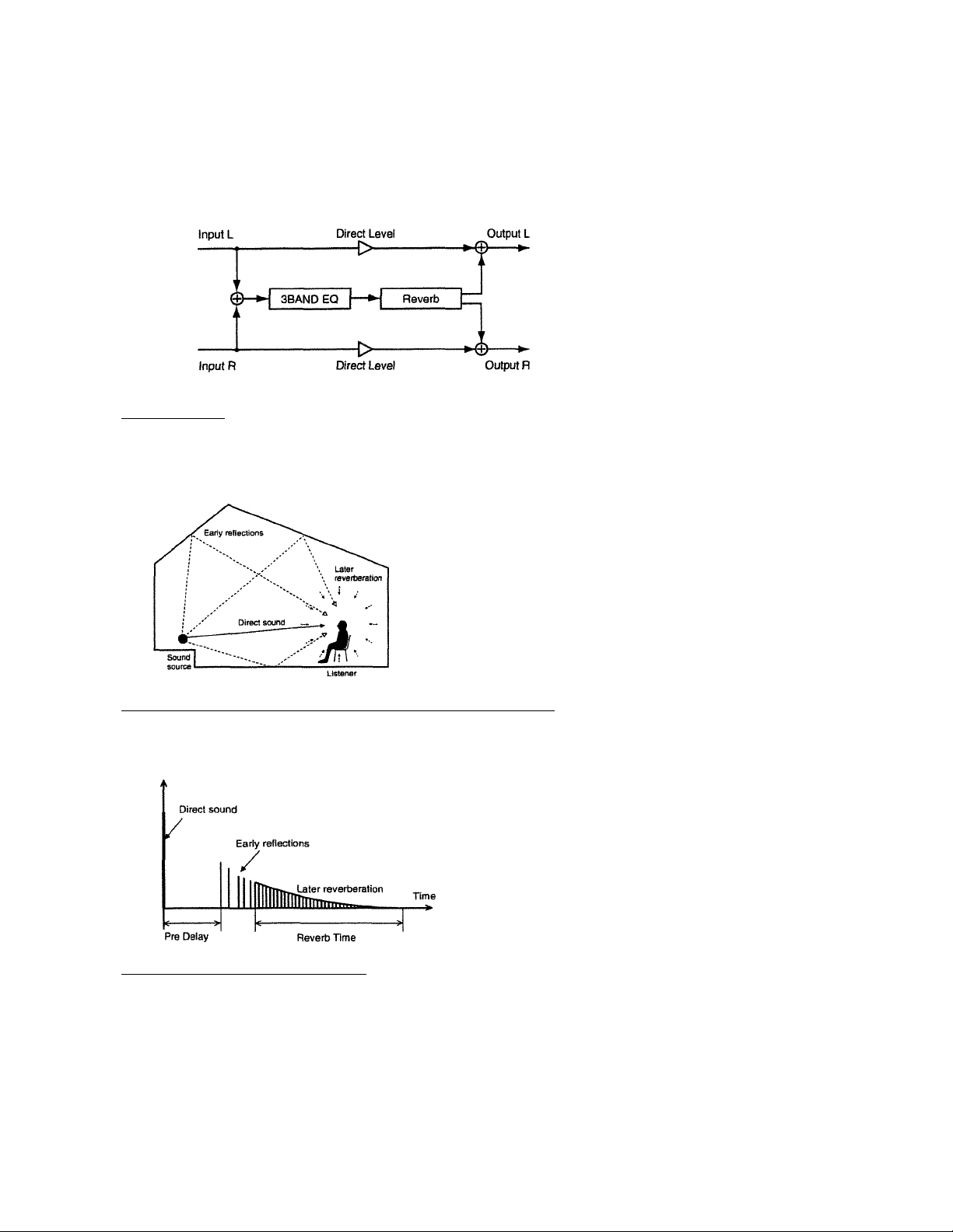
Algorithm List
Reverb
This feature adds reverberation to the sound to simulate the size of space such as a hall and a room.
Sound types
Sounds around us can be analyzed and categorized into three types: direct sounds, early reflections and
reverberation. A direct sound is the sound that reaches the listener directly from the source. An early reflection is
the sound that has rebounded from the wall once, twice or several times. A reverberation is the sound we hear
after sound reflections are repeated many times.
II
.
.. .
.. .. ... ... ..
11^
Relationship between sound and time
Reflected sound reach the listener in the following sequence. The pre-delay is the time from when the direct
sound is heard until the reverb is heard. The reverb time is the time over which the reverb decays to silence.
Level
Reverb sound quality
The sound quality of a reverb is affected by materials of the walls and other members from which the sound is
rebounded. This is because the degree of attenuation in the high and low frequency bands varies. HF-Damp Gain
and LF-Damp Gain are provided so that you can adjust such attenuation degrees. The smaller the value becomes,
the steeper the degree of attenuation of the reverberation becomes severer in the high and low frequency bands.
In addition, in order to obtain softer reverberation, make the frequency lower by using HF-Damp Frequency
(HiFreq-Damp Freq). In order to obtain harder reverberation, make the frequency higher by using LF-Damp
Frequency (LoFreq-Damp Freq).
26
Page 27

Parameter (full name) Setting Function
EQ (Equalizer)
EQ (Switch)
LowType (Low Type) Shiv, Peak Sets the type of the low frequency band equalizer
Low.G (Low Gain) -12-+12dB Sets the boost/cut amount in the low frequency band.
Low.F (Low Frequency)
Low.Q (Low Q) 0.3-10.0
Mid.G (Middle Gain) -12-+12dB Sets the boost/cut amount in the middle frequency band.
Mid.F (Middle Frequency) 200-8000 Hz
Mid.Q (Middle Q) 0.3-10.0
Hi Type (High Type)
Hi.G (High Gain)
Hi.F (High Frequency) 1.4-20.0 kHz
Hi.Q (High Q) 0.3-10.0
Out Level (Output Level) 0-100
Algorithm List
On, Off
20 - 2000 Hz
Shiv, Peak Sets the type of the high frequency band equalizer (Shlving
-12-+12dB
Turns the equalizer on or off.
(Shlving type or peaking type).
Sets the center frequency in the low frequency band.
Sets the width of the area around the low frequency that
will be affected by the gain settings.1 *1
Sets the center frequency in the middle frequency band.
Sets the width of the area around the middle frequency that
will be affected by the gain settings.
type or peaking type).
Sets the boost/cut amount in the high frequency band.
Sets the center frequency in the high frequency band.
Sets the width of the area around the high frequency that
will be affected by the gain settings. 1 * 1
Sets the volume after passing through the equalizer.
Reverb;
i: Adds reverberation.
RoomSize (Room Size) 5-40 m Sets the size of the room.
Time (Reverb Time) 0.1-10.0 sec.
EFLevBl (Effect Level)
DiLevel (Direct Level) -100-100 Sets the volume of the direct sound.
PreDLY (Pre-Delay) 0-200 ms
Diffusio (Diffusion) 0-100
Density (Density) 0-100 Sets the density of the reverb sound.
ER Level (Early Reflection Level) OtolOO Sets the volume of the early reflection.
LD.G (LF-Damp Gain)
LD.F (LF-Damp Frequency)
HD.G (HF-Damp Gain) -36-0 dB Sets the degree of attenuation of the reverb in the high
HD.F (HF-Damp Frequency) 1.0-20.0 kHz
HiCF (High Cut Frequency)
-100-100 Sets the volume of the reverb sound.
-36-0 dB Sets the degree of attenuation of the reverb in the low
50-4000 Hz Sets the frequency cm which the reverb starts attenuating in
0.2-20.0 kHz Sets the frequency for which the high frequency band
Sets the time length of the reverb sound.
Sets the time until the reverb sound appears.
Sets the extent of diffusion of the early reflection sound.
frequency band.
the low frequency band.
frequency band.
Sets the frequency on which the reverb starts attenuating in
the high frequency band.
elements of the reverb are cut.
*1: If Low Type (LowType) or High T}rpe (Hi Type) is set to "Shiv (Shlving Type)," the setting for LowQ or High Q
is invalid.
27
Page 28
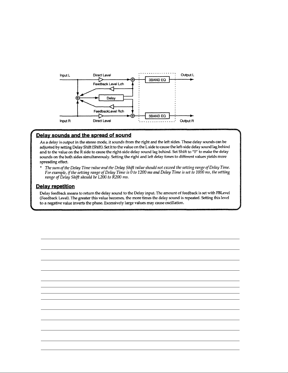
Algorithm List
Delay
Delay is a feature to add a delayed sound to the direct sound in order to add thickness to the sound or to yield a
special effect.
Parameter (full name)
Setting
Function
DLY(Delay): Adds a delayed sound to the direct sound, adding depth to the sound or creating special effects.
Delay (Switch) On, Off Turns the delay on or off.
Time (Delay Time)
Shft (Delay Shift)
L-FBLvl (Lch Feedback Level)
R-FBLvl (Rch Feedback Level) -100-100 Sets the amount of the right-side delay should be returned
L-Level (Lch Effect Level)
R-Level (Rch Effect Level)
DILevel (Direct Level)
LD.G (LF-Damp Gain) -36-0 dB Sets the degree of attenuation in the low frequency band for
LD.F (LF-Damp Frequency) 50-4000 Hz Sets the frequency at which attenuation in the tow
HD.G (HF-Damp Gain) -36-0 dB Sets the degree of attenuation in the high frequency band
HD.F (HF-Damp Frequency)
0-1200 ms
L1200-0-R1200 ms Sets the delay time difference between the right and ieft
-100-100 Sets the amount of the left-side delay should be returned to
-100-100 Sets the volume for the left-side delay sound.
-100-100
-100-100 Sets the volume of the direct sound.
1.0-20.0 kHz Sets the frequency at which attenuation in the high
Sets the time from direct sound until when the delay sound
is heard. *1
delay sounds.
the delay Input.
to the delay input.
Sets the volume for the right-side deiay sound.
the delay sound fed back.
frequency band starts to the delay sound fed back.
for the delay sound fed back.
frequency band starts to the delay sound fed back.
28
Page 29

EQ (Equalizer)
EQ (Switch) On, Off
LowType (Low Type)
Low.G (Low Gain) -12-+12dB
Low.F (Low Frequency)
Low.Q (Low Q) 0.3-10.0
Mid.G (Middle Gain)
Mid.F (Middle Frequency)
Mid.Q (Middle Q)
Hi Type (High Type)
Hi.G (High Gain)
Hi.F (High Frequency) 1.4-20.0 kHz
Hi.Q (High Q) 0.3-10.0
Out Level (Output Level)
Shiv, Peak
20 - 2000 Hz
-12-+12dB
200-8000 Hz
0.3-10.0
Shiv, Peak
-12-+12dB
0-100
Algorithm List
Turns the equalizer on or off.
Sets the type of the low frequency band equalizer
(Shlving type or peaking type).
Sets the boost/cut amount in the low frequency band.
Sets the center frequency in the low frequency band.
Sets the width of the area around the low frequency that
will be affected by the gain settings.1 *2
Sets the boost/cut amount in the middle frequency band.
Sets the center frequency in the middle frequency band.
Sets the width of the area around the middle frequency that
will be affected by the gain settings.
Sets the type of the high frequency band equalizer (Shlving
type or peaking type).
Sets the boost/cut amount in the high frequency band.
Sets the center frequency in the high frequency band.
Sets the width of the area around the high frequency that
will be affected by the gain settings.1 *2
Sets the volume after passing through the equalizer.
*1; The sum of the Delay Time (Time) value and the Delay Shift (Shift) value should not exceed the setting range of
Delay Time. For example, if Delay Time is set to 1000 ms, the setting range of Delay Shift is L200 to R200 ms.
*2: If Low Type (LowType) or Hi Type (High Type) is set to "Shiv (Shlving Type)," the setting for LowQ or High Q
is invalid.
29
Page 30
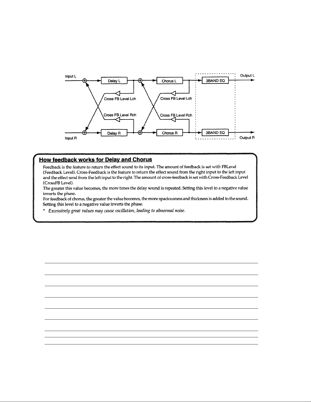
Algorithm List
StDiy-Chorus (Stereo Delay Chorus)
Delay and Chorus can be combined to create spaciousness.
Parameter (full name)
Setting Function
DLY(Delay): Adds a delayed sound to the direct sound, adding depth to the sound or creating special effects.
Delay (Switch) On, Off Turns the delay on or off.
Time (Delay Time)
Shift (Delay Shift)
L-FBLvl (Lch Feedback Level)
R-FBLvl (Rch Feedback Level)
L-CFBLv (Lch Cross-Feedback Level)
R-CFBLv(Rch Cross-Feedback Level) -100-100 Sets the amount of the right-side delay should be returned
EFLevel (Effect Level)
DiLevel (Direct Level) -100-100 Sets the volume of the direct sound.
0-500 ms Sets the time from direct sound until when the delay sound
L500-0-R500 ms
-100-100 Sets the amount of the left-side delay should be returned to
-100-100 Sets the amount of the right-side delay should be returned
-100-100 Sets the amount of the left-side delay should be returned to
-100-100
is heard. *1
Sets the delay time difference between the right and left
delay sounds.
the left delay input.
to the right delay input.
the right delay input.
to the left delay input.
Sets the volume of the delay sound.
30
Page 31

Algorithm List
CHO (Chorus):
Chorus (Switch)
Rate (Rate)
Depth (Depth)
EFLevel (Effect Level)
DILevel (Direct Level)
PreDLY (Pre-Delay)
L-FBLvl (Lch Feedback Level)
R-FBLvl (Rch Feedback Level)
L-CFBLv (Lch Cross-Feedback Level)
R-CFBLv(Rch Cross-Feedback Level)
ualizer)
EQ (Switch)
LowType (Low Type)
Low.G (Low Gain)
Low.F (Low Frequency)
Low.Q (Low Q)
Mid.G (Middle Gain)
Mid.F (Middle Frequency)
Mid.Q (Middle Q)
Hi Type (High Type)
Hi.G (High Gain)
Hi.F (High Frequency)
Hi.Q (High Q)
Out Level (Output Level)
Adds spaciousness and depth to the sound.
On, Off Turns the chorus on or off.
0.1-10.0 kHz
0-100
-100-100
-100-100
0-50 ms
-100-100 Sets the amount of the left-side chorus sound should be
-100-100
-100-100
-100-100
On, Off Turns the equalizer on or off.
Shiv, Peak
-12-+12dB
20 - 2000 Hz
0.3-10.0
-12-+12dB
200-8000 Hz
0.3-10.0
Shiv, Peak
-12-+12dB Sets the boost/cut amount In the high frequency band.
1.4-20.0 kHz
0.3-10.0
0-100
Sets the rate of modulation.
Sets the depth of modulation.
Sets the volume of the chorus sound.
Sets the volume of the direct sound.
Sets the time delay from when the direct sound begins until
the processed sound is heard.
returned to the left chorus input.
Sets the amount of the right-side chorus sound should be
returned to the right chorus input.
Sets the amount of the left-side chorus sound should be
returned to the right chorus input.
Sets the amount of the right-side chorus sound should be
returned to the left chorus input.
Sets the type of the low frequency band equalizer
(Shlving type or peaking type).
Sets the boost/cut amount in the low frequency band.
Sets the center frequency in the low frequency band.
Sets the width of the area around the low frequency that
will be affected by the gain settings.1 *2
Sets the boost/cut amount in the middle frequency band.
Sets the center frequency in the middle frequency band.
Sets the width of the area around the middle frequency that
will be affected by the gain settings.
Sets the type of the high frequency band equalizer (Shlving
type or peaking type).
Sets the center frequency in the high frequency band.
Sets the width of the area around the high frequency that
will be affected by the gain settings.1 *2
Sets the volume after passing through the equalizer.
*1: The sum of the Delay Time (Time) value and the Delay Shift (Shift) value should not exceed the setting range of
Delay Time. For example, if the delay time is .set to 300 ms, the setting range of Delay Shift is L200 to R200 ms.
*2: If LowType (Low Type) or Hi Typ>e (High Type) is set to "Shiv (Shlving Type)," the setting for LowQ or High Q
is invalid.
31
Page 32

Algorithm List
StPS-Delay (Stereo Pitch Shifter Delay)
Changes the pitch of the direct sound. Corrects vocals out of tune or adds thickness to the sound by mixing the
direct sound and a sound at a shifted pitch.
Setting up pitch
Chromatic Pitch (Cromatic) is used for major pitch variation while Fine Pitch (Fine) is used for fine adjustment.
Setting up slightly different pitches for the right and left gives thickness to the sound.
Parameter (full name)
Pitch Shifter Deiay
PS-Delay (Switch)
L-CP (Lch Chromatic Pitch) -12-12
R-CP (Rch Chromatic Pitch)
L-F.P (Lch Rne Pitch)
R-F.P (Rch Fine Pitch)
L-PDLY (Lch Pre-Delay)
R-PDLY (Rch Pre-Delay) 0-50 ms
L-FBD (Lch Feedback Delay Time)
R-FBD (Rch Feedback Delay Time) 0-500 ms
L-FBLvl (Lch Feedback Level)
R-FBLvl (Rch Feedback Level)
L-CFBLv (Lch Cross-Feedback Level) -100-100 Sets the amount of the left-side sound at a shifter pitch
R-CFBLv (Rch Cross-Feedback Level) -100-100 Sets the amount of the right-side sound at a shitted pith
EFLevel (Effect Level) -100-100 Sets the volume of the sound at a shifter pitch.
DiLevel (Direct Level)
: Shifts the pitch.
Setting Function
On, Off Turns the pitch shifter on or off.
Sets the left-side pitch variation (by serriitone).
-12-12
-100-100 Sets the left-side pitch variation (by cent).
-100-100
0-50 ms Sets the time from when the direct sound Is output until
0-500 ms Sets the feedback repetition cycle for the left-side delay
-100-100 Sets the amount of the left-side sound at a shifted pitch
-100-100 Sets the amount of the right-side sound at a shifted pitch
-100-100 Sets the volume of the direct sound.
Sets the right-side pitch variation (by semitone).
Sets the right-side pitch variation (by cent).
when the left-side sound at a shifted pitch is output.
Sets the time from when the direct sound is output until
when the right-side sound at a shifted pitch is output.
sound.
Sets the feedback repetition cycle for the right-side delay sound.
should be returned to the left pitch shifter input.
should be returned to the right-side pitch shifter input.
should be returned to the right-side pitch shifter input.
should be returned to the left-side pitch shifter input.
32
Page 33

EQ (Equalizer)
EQ (Switch) On, Off
LowType (Low Type) Shiv, Peak
Low.G (Low Gain) -12-+12dB
Low.F (Low Frequency)
Low.Q (Low Q) 0.3-10.0
Mid.G (Middie Gain) -12-+12dB
Mid.F (Middie Frequency)
Mid.Q (Middie Q) 0.3-10.0
Hi Type (High Type)
Hi.G (High Gain) -12-+12dB
Hi.F (High Frequency)
Hi.Q (High Q)
Out Levei (Output Levei)
20 - 2000 Hz
200-8000 Hz
Shiv, Peak
1.4-20.0 kHz
0.3-10.0
0-100
Algorithm List
Turns the equaiizer on or off.
Sets the type of the iow frequency band equaiizer
(Shiving type or peaking type).
Sets the boost/cut amount in the iow frequency band.
Sets the center frequency in the tow frequency band.
Sets the width of the area around the iow frequency that
wiii be affected by the gain settings.1 *1
Sets the boost/cut amount in the middle frequency band.
Sets the center frequency in the middle frequency band.
Sets the width of the area around the middle frequency that
will be affected by the gain settings.
Sets the type of the high frequency band equalizer (Shlving
type or peaking type).
Sets the boost/cut amount in the high frequency band.
Sets the center frequency in the high frequency band.
Sets the width of the area around the high frequency that
will be affected by the gain settings.1 *1
Sets the volume after passing through the equalizer.
*1: If Low Type (LowTypc) or High Type (Hi Type) is set to "Shiv (Shlving Type)," the setting for LowQ or High Q
is invalid.
33
Page 34

Algorithm List
Vocoder
The vocoder creates "talking instrument" effects. To use Vocoder, input an instrumental sound into the left
channel and a vocal sound into the right channel. The instrumental sound is split into ten frequency bands to be
processed according to its frequency components.
Output L
Input R (MIc)
Output R
1^
Instrumental sounds are input into the L-channel side of the effect. Therefore, it is required to insert and connect
"Lch" of the effect to the channel handling instrumental sounds. Similarly, vocal sounds are input into the R-
channel side of the effect. Insert and connect "Rch" of the effect to the channel handling vocal sounds.
Tips for using Vocoder
It is a good idea to choose instrumental sounds containing a lot of overtones. Recommended .sounds include those
with saw-tooth waveforms such as strings and distorted guitar sounds.
Ni
.................................................................
Parameter (full name)
VOC (Vocoder): The pitch is specified with the instrumental sound while the tone is output in vocals.
V.Char 1-10 (Voice Characters) 0-100 Sets the volume by frequency band. These are used to
CHO (Chorus):
Chorus (Switch)
Rate (Rate)
Depth (Depth)
EFLevel (Effect Level)
DiLevel (Direct Level)
PreDLY (Pre-Delay) 0-50 ms
FBLevel (Feedback Level)
....................................................................
Setting
.,,».1,1...—.------------------
Function
change the vocoder tone.
Adds spaciousness and depth to the sound.
On, Off Tumsthechonjsonoroff.
0.1-10.0 Hz Sets the rate of modulation.
0-100 Sets the depth of modulation.
-100-100 Sets the volume of the chorus sound.
-100-100 Sets the volume of the direct sound.
Sets the time delay from when the direct sound begins until
the processed sound is heard.
-100-100 Sets the amount of the chorus sound should be returned to
the chorus input.
---
34
Page 35

2ch RSS
Gives each of the sounds input into the respective channels three-dimensional locations.
Algorithm List
Input A
Input B
Output L
Output R
Input A is input into the L-channel side of the effect. Therefore, it is required to insert and connect "Lch" of the
effect to the channel handling Input A. Similarly, Input B is input into the R-channel side of the effect. Insert and
connect "Rch" of the effect to the channel handling Input B.
Do not output the direct sound.
What is RSS?
It stands for Roland Sound Space. This is one of the Roland's proprietary effect technologies that enables threedimensional location of the sound source on the ordinary stereo system. Not only control on effect for the front
and the sides of the audience, this technology provides controls on directions (azimuth) such as up, down and
rear as well as control on distance to localize the sound source.
Up
RSS:
.1 U B
Parameter (full name) Setting Function
Gives sounds three-dimensional locations.
A-Azim (Ach Azimuth)
A-Elev (Ach Elevation) -90-90'
B-Azim (Bch Azimuth)
B-Elev (Bch Elevation) -90-90'
-180-180' Sets output directions, front back, right and left, for the
Input A channel.
Sets output directions, up and down, for the Input A
channel.
-180-180' Sets output directions, front, back, right and left, for the
Input B channel.
Sets output directions, up and down, for the Input B
channel.
Continued.
35
Page 36

Algorithm List
Precautions for usinc^ RSS
In order to obtain the maximum effect from the RSS, observe the following points.
• Acoustically "dead" rooms are most suitable.
• A single-way speaker is suited. However, a multi-way type will do if it incorporates the coaxial or virtual
coaxial system.
• Place the speakers as far as possible from the wedls on the sides.
• Do not separate the right and left speakers too much.
• Recommended sweet spots for listening are as follows:
Labeling on RSS product package
In order to allow RSS to demonstrate its maximum performance, it is important to specify listening environment.
For sale, we recommend that you should attach the following labeling on the packages of your products produced
by using RSS patches.
i For Stereo Speakers
This sound is made to be played specifically through speakers.
The proper effect cannot be obtained if listened to through headphones.
Less reflections from the wall
or floor are better.
Speaker should be placed
36
Page 37

Delay RSS
The right-side, left-side and center Delay sounds can be set separately. As RSS is connected to both the right and
left outputs, the sound image of the sound from the left-side channel is localized at 90" to the left and that of the
sound from the right-side channel at 90" to the right. The center Delay output can receive the Feedback effect.
Algorithm List
Input L
Input R
Direct Level
Direct Level
The location is fixed; no azimuth or elevation can be specified.
Parameter (full name) Setting
DRS (Delay RSS):
Time (Delay Time)
Shft (Delay Shift) L1200-0-R1200 ms
C-Tim (Center Delay Time) 0-1200 ms
RSS LvI (RSS Level) 0-100
C-Lvl (Center Level)
FBLevel (Feedback Level) -100-100
EFLevel (Effect Level) -100-100
DiLevel (Direct Level) -100-100
LD.G (LF-Damp Gain)
LD.F (LF-Damp Frequency) 50-^000 Hz
HD.G (HF-Damp Gain)
HD.F (HF-Damp Frequency) 1.0-20.0 kHz
Gives three-dimensional location to Delay sounds.
0-1200 ms Sets the time from direct sound until when the left and right
0-100
-36-0 dB
-36-0 dB Sets the degree of attenuation in the high frequency band
Output L
Output R
Function
delay sound is heard.
Sets the balance of the right and left delay times.
Sets the time from direct sound until when the center delay
sound is heard.
Sets the volume of the RSS sound.
Sets the volume for the center delay sound.
Sets the amount of the center delay sound should be
returned to the delay input.
Sets the volume of the delay RSS sound.
Sets the volume of the direct sound.
Sets the degree of attenuation in the low frequency band for
the center delay sound returned to the input.
Sets the frequency at which attenuation in the low
frequency band starts for the center delay sound returned
to the Input.
for the center delay sound returned to the input.
Sets the frequency at which attenuation in the high
frequency band starts for the center delay sound returned
to the input.
37
Page 38

Algorithm List
Chorus RSS
RSS is connected to the Chorus output. The sound image is defined with the sound from the left-side channel
located at left 90” and the sound from the right-side channel at right 90°.
Input L
Input R
Direct Level
Direct Level
Location is fixed; no azimuth or elevation can be sprecified.
Parameter (full name)
CRS (Chorus RSS)
Rate (Chonjs Rate)
Depth (Chorus Depth)
EFLevel (Effect Level) -100-100
DILevel (Direct Level) -100-100
: Locates chorus sounds three-dimensionaliy.
Setting Function
0.1-10.0 Hz Sets the rate of modulation.
0-100
Output L
Output R
Sets the depth of modulation.
Sets the volume of the chorus RSS sound.
Sets the volume of the direct sound.
38
Page 39

GuitarMulti 1-3
These provide multi-effects for guitar sounds suited for rock. Guitar Multi 1 through 3 differ in the degree of
sound distortion. Guitar Multi 1 provides the highest degree of distortion and Guitar-Multi 3 the lowest.
Input L
Algorithm List
Input R
r
Usage of Guitar Multi 1 through 3
The basic configuration is almost identical for all of Guitar-Multi 1 through 3. The only difference is the type of
the second effect (heavy metal, distortion, and overdrive). Select Guitar Multi 1 to add severe distortion to the
sound, and select Guitar Multi 3 for soft distortion as that achieved with the vacuum tube amplifier.
Adding Wah effect by changing input volume
Typically, Auto-Wah provides an automatic wah effect at the cycle set with Rate (Rate).
Alternatively, you can give wah effect according to changes of input volume. For example, you can apply the wah
effect so that it reflects changes in picking on the guitar. First, adjust sensitivity for changes in input volume by
using Sense (Sens). Set it to a larger value for finer subtlety. After that, you simply dedde the direction into which
the filter should be moved by entering a setting for Polarity (Pol).
Selecting Guitar Amplifier
You can select which typ« of Guitar Amplifier to use with Mode (Mode) under Guitar Amplifier Simulator.
Small:
Built In:
2 Stack:
3 Stack:
Small-sized amplifier
Built-in type amplifier
Large-sized two-deck stacked amplifiers
Large-sized three-deck stacked amplifiers
Compressors used in Guitar Muiti 1 through 3
Compressors used in Guitar Multi 1 through 3 are designed to accommodate playing of the guitar, providing a
slightly different effect from ordinary compressors. Compressors for the guitar unifies volumes by suppressing
signals at high levels and enhancing signals at low levels.
Unlike these, ordinary compressors simply suppress signals at high levels.
Continued..
39
Page 40

Algorithm List
Parameter (full name)
Setting Function
CMP (Compressor):Compresses the entire output signals when the input volume exceeds a specified value.
Comp (Switch) On, Off Turns the compressor on or off.________________________
Attack (Attack)
Level (Level)
Sustain (Sustain) 0-100
Tone (Tone)
0-100
0-100
-50-50
Sets the strength of attack whan a sound is input.
Sets the volume of the compressor sound.
Sets the time over which low level signals are boosted to a
constant volume.
Sets the tone color.
MTL (Heavy Metal) / DST (Distortion) / ODV (Overdrive): Gives distortion to the sound.
(Switch) On, Off Turns the metal, distortion or overdrive on or off.
Gain (Gain) 0-100
Level (Level)
HiGain (High Gain)
MidGain (Middle Gain)
LowGain (Low Gain)
Tone (Tone)
NS (Noise Suppressor):
NoiseSup (Switch)
Thresh (Threshold)
Release (Release)
0-100
-100-100
-100-100
-100-100
0-100
Mutes noise in the silent mode.
On, Off
0-100
0-100
Sets the degree of the distortion.
Sets the volume of the metal, distortion or overdrive sound.
Sets the boost/cut amount in the high frequency band,
(only for Metal)
Sets the boost/cut amount in the middle frequency band,
(only for Metal)
Sets the boost/cut amount in the low frequency band,
(only for Metal)
Sets the tone color, (for Distortion/Overdrive only)
Turns »le noise suppressor on or off.
Sets the level to start muting noise.
Sets the time over which the volume will drop to 0 after the
noise starts being muted.
______
_________________
____
WAH (Auto Wah):
Wah (Switch)
Mode (Mode) LPF, BPF
Pol (Polarity)
Freq (Frequency)
Level (Level)
Peak (Peak)
Sens (Sense) 0-100
Rate (Rate)
Depth (Depth) 0-100
Adds the wah effect.
On, Off
Up, Down
0-100
0-100
0-100
0.1-10.0 Hz
AMP (Guitar Amplifier Simulator): Simulates Guitar Amplifier.
G.AmpSIm (Switch) On, Off
Mode (Mode) See the column on
the previous page.
Turns the auto wah on or off.
Set to “BPP for the wah effect in a narrow range of
frequencies and to “LPP for wah effect in a broad range of
frequencies.
Activated only for adding the wah effect according to input
volume changes. Set to “Up" for moving the filter to a higher
frequency and "Down” for moving it to a lower frequency.
Sets the frequency at which the wah effect starts working.
Sets the volume of the wah sound.
Sets the degree of the wah effect applied at around the
frequency.
Normally “0.”
Sets sensitivity for input volume changes for adding the
wah effect according to input volume changes.
Sets the rate at which the wah effect will be cyclically modulated.
Sets the depth at which the wah effect will be cyclically modulated.
Turns the guitar amplifier simulator on or off.
Type of the guitar amplifier.
40
Page 41

Algorithm List
FLG (Pianger):
Ranger (Switch)
Rate (Rate) 0.1-10.0 Hz
Depth (Depth)
Manual (Manual)
Reso(Resonance)
Adds effects similar to ascending/descending sound of a jet.
On, Oft Turns the flanger on or off.
Sets the rate of modulation for the flanger.
0-100
0-100
0-100
Sets the depth of modulation for the flanger.
Sets the center frequency subject to application of the
flanger effect.
Enhances frequency components at around the center
frequency set with Manual.
¡lay): Adds a delayed sound to the direct sound, adding depth to the sound or creating speciai effect
Delay (Switch) On, Off
Time (Delay Time)
Shft (Shift)
FBTim (Feedback Delay Time)
FBLevel (Feedback Level)
EFLevel (Effect Level)
DILevel (Direct Level)
0-1000 ms
L1000-0-R1000 ms
0-1000 ms
-100-100
-100-100
-100-100 Sets the volume of the direct sound.
*1: The sum of the Delay Time value and the Delay Shift value should not exceed the setting range of Delay Time.
For example, if Delay Time is set to 800 ms, the setting range of Delay Shift is L200 to R200 ms.
Turns the delay on or off.
Sets the time from direct sound until when the delay sound
Is heard.* *1
Sets the delay time difference between the right and left
delay sounds.
Sets the feedback repetition cycle.
Sets the amount of the delay sound should be returned to
the delay input.
Sets the volume of the delay sound.
41
Page 42

Algorithm List
Vocal Multi
This feature provides a multi-effect suited for vocals.
Input L
Input R
t
Cutting distortion in vocals
Limiter can be used to suppress signals at a high level to prevent sound distortion. To do this, follow the steps
below:
Mode (Mode):
Limiter Threshold (Thresh):
Limiter Release (Release):
Limiter Level (Level):
Cutting the sibilant sounds of a voice.
De-esser can be used to cut off sibilant sounds contained in vocal sounds to achieve softer sound quality. To do
this, follow the steps below:
Mode (Mode):
De-esser Sense (Sens):
De-esser Frequency (Freq):
Limiter
Sets the volume at which soimd distortion starts being suppressed.
Determines the time that elapses before the input level becomes off after it drops
below the Limiter Threshold.
Decides the volume after passing through Limiter.
De-esser
Sets the degree of the De-esser effect.
Sets the frequency at which De-esser effect starts working.
Parameter (full name)
NS (Noise Suppressor);
NoiseSup (Switch)
Thresh (Threshold)
Release (Release)
LD (Limiter / De-esser):
LMT/DES (Switch)
Mode (Mode)
Thresh (Limiter Threshold)
Release (Limiter Release)
Level (Limiter Level) 0-100
ENH (Enhancer):
Enhancer (Switch)
Sens(Sense)
Freq (Frequency)
Mix Lev (Mix Level)
Level (Level)
Setting
Function
Mutes noise in the silent mode.
On. Off
0-100
0-100
Turns the noise suppressor on or off.
Sets the level to start muting noise.
Sets the time over which the volume will drop to 0 after the
noise starts being muted.
Suppresses signals at high levels to control distortion /
Suppresses the annoying s-consonant.
On, Off Turns the limiter/de-esser on or off.
Limiter, De-esser
0-100
0-100
Selects limiter or de-esser.
Sets the volume at which sound distortion starts being
suppressed.
Sets the time until when the limiter will turn off after the input
level falls the limiter Threshold (Thresh).
Sets the volume of the limiter sound.
Accentuates the sound and push the sound forward.
On, Off Turns the enhancer on or off.
0-100 Sets the degree of the enhancer effect desired.
1.0-10.0 kHz
0-100 Sets the amount of the enhancer sound should be mixed
0-100
Sets the frequency at which the enhancer effect starts working.
into the direct sound.
Sets the volume of the enhancer sound.
42
Page 43

EQ (Equalizer)
EQ (Switch) On, Off
LowType (Low Type)
Low.G (Low Gain)
Low.F (Low Frequency) 20 - 2000 Hz
Low.Q (Low Q) 0.3-10.0
Mid.G (Middle Gain)
Mid.F (Middle Frequency) 200-8000 Hz
Mid.Q (Middle Q)
Hi Type (High Type)
Hi.G (High Gain) -12-+12dB
Hi.F (High Frequency) 1.4-20.0 kHz
Hi.Q (High Q) 0.3-10.0
Out Level (Output Level) 0-100
ch Shifter): Shifts the pitch.
P.Shifter (Switch)
C.Pitch (Chromatic Pitch) -12-12
F.Pitch (Fine Pitch) -100-100
EFLevel (Effect Level) -100-100
DiLevel (Direct Level) -100-100
Algorithm List
Turns the equalizer on or off.
Shiv, Peak Sets the type of the low frequency band equalizer
-12-+12dB
-12-+12dB Sets the boost/cut amount in the middle frequency band.
0.3-10.0
Shiv, Peak Sets the type of the high frequency band equalizer (Shlving
On, Off
(Shlving type or peaking type).
Sets the boost/cut amount in the low frequency band.
Sets the center frequency in the low frequency band.
Sets the width of the area around the low frequency that
will be affected by the gain settings.1 *1
Sets the center frequency in the middle frequency band.
Sets the width of the area around the middle frequency that
will be affected by the gain settings.
type or peaking type).
Sets the boost/cut amount in the high frequency band.
Sets the center frequency in the high frequency band.
Sets the width of the area around the high frequency that
will be affected by the gain settings.1 *1
Sets the volume after passing through the equalizer.
Turns the pitch shifter on or off.
Pitch variation (by semitone)
Pitch variation (by cent)
Sets the volume of the pitch shift sound.
Sets the volume of the direct sound.
DLY(Delay):Adds a delayed sound to the direct sound, adding depth to the sound or creating special effects.
Delay (Switch) On. Off
Time (Delay Time)
FBLevel (Feedback Level) -100-100
EFLevel (Effect Level) -100-100
DiLevel (Direct Level)
CHO (Chorus):
Chorus (Switch)
Rate (Rate) 0.1-10.0 Hz Sets the rate of modulation.
Depth (Depth)
EFLevel (Effect Level) -100-100
DiLevel (Direct Level) -100-100
PreDLY (Pre-Delay) 0-50 ms Sets the time delay from when the direct sound begins until
Adds spaciousness and thickness to the sound.
0-1000 ms Sets the time from direct sound until when the delay sound
-100-100 Sets the volume of the direct sound.
On, Off
0-100
*1: If Low Type (LowType) or High T)T3e (Hi Type) is set to "Shiv (Shlving Type)," the setting for LowQ or High Q
is invalid.
Turns the delay on or off.
is heard.
Sets the amount of the delay sound should be returned to
the delay input.
Sets the volume of the delay sound.
Turns the chorus on or off.
Sets the depth of modulation.
Sets the volume of the chorus sound.
Sets the volume of the direct sound,
the processed sound is heard.
43
Page 44

Algorithm List
Rotary
Simulates a rotary speaker. Behaviors of high and low frequency band Roters can be set up separately, allowing
realistic modeling of unique surging sensation. This effect is suited for organ sounds.
Input L
Input R
Parameter (full name) Setting
NS (Noise Suppressor):
NoiseSup (Switch)
Thresh (Threshold)
Release (Release)
ODV (Overdrive):
OvDrive (Switch)
Gain (Gain)
Level (Level)
ROT (Rotary Speaker):
LRate (Low Rate)
HRate (High Rate)
Mutes noise in the siient mode.
On, Off
0-100 Sets the level to start muting noise.
0-100
Adds distortion to the sound.
On, Off
0-100
0-100 Sets the volume of the overdrive sound.
Simulates a rotary speaker.
0.1-10.0 Hz
0.1-10.0 Hz Sets the rotary frequency of the high frequency band roter.
Function
Turns the noise suppressor on or off.
Sets the time over which the volume will drop to 0 after the
noise starts being muted.
Turns overdrive on or off.
Sets the degree of sound distortion.
Sets the rotary frequency of the low frequency band roter.
GuifarAmpSim (Guitor Amplifier Simulator)
Simulates a guitar amplifier.
Input L
Input R
44
Page 45

Algorithm List
Pre-amplifier
Simulates the pre-amplifier section of a guitar amplifier. 14 types of pre-amplifiers that can be simulated are listed
below: The type can be set with pre-amplifier Type.
JC-120: The sound of a Roland.
Clean Twin: The sound of standard built-in type vacuum tube amplifier.
Match Drive: The sound of a recent vacuum tube amplifier widely used in blues, rock and fusion.
BG Lead: The sound of a vacuum tube amplifier representative of the late 70's through 80's.
MS1959<I>: The sound of the large vacuum tube amplifier stack that was indispensable to the British
hard rock of the 70's, with input I connected.
MS1959<II>: The same amplifier as MS1959 <I>, but with input II connected.
MS1959<I+II>: The same amplifier as MS1959 <I>, but with input I and II connected in parallel.
SLDN Lead: The sound of a vacuum tube amplifier usable in a wide variety of styles.
Metal 5150: The sound of a large vacuum tube amplifier suitable for heavy metal.
Metal Lead: A metal lead sound with a distinctive mid-range.
OD-1 : The sound of the BOSS OD-1 compact effector.
OD-2Turbo: The sound of the BOSS OD-2 compact effector with the Turbo switch on.
Distortion: Distortion sound
Fuzz: Fuzz sound
* With JC-120, Clean Twin or BG Lead is selected, turning Bright (Bright) on generates clear-cut bright sound.
Speaker simulator
Simulates a speaker. The 12 types of speakers as listed below can be simulated: The t)pe is set with Speaker Type.
The type can be set with Speaker Type.
Type
Small
Middle
JC-120
Built In 1 Open back enclosure
Built In 2
Built In 3
Built In 4
BG Stack 1
BG Stack 2
MS Stack 1
MS Stack 2
Metal Stack
Cabinet
(size (in inch), number of units)
Small open-back enclosure 10
Open back enclosure
Open back enclosure
Open back enclosure 12x2 Condenser microphone
Open back enclosure 12x2
Open back enclosure 12x2 Condenser microphone
Sealed enclosure 12x2
Large sealed enclosure 12x2 Condenser microphone
Large sealed enclosure 12x4 Condenser microphone
Large sealed enclosure 12x4
Large double stack 12x4 Condenser microphone
Speaker Microphone
D)mamic microphone
12x1
12x2
12x2 Dynamic microphone
Dynamic microphone
Dynamic microphone
Condenser microphone
Condenser microphone
Condenser microphone
Recommended combinations of Pre-amplifier and Speaker
Pre-amplifler Type
BG Lead
MS1959II
MS1959I+I1 BG Stack 1, BG Stack 2, Metal Stack
SLDN Lead
Metal 5150
Metal Lead BG Stack 1, BG Stack 2, Metal Stack
OD-2 Turbo
Distortion
Fuzz Built In 1 - 4
Speaker Type
BG Stack 1, BG Stack 2, Middle
BG Stack 1, BG Stack 2, Metal Stack
BG Stack 1, BG Stack 2, Metal Stack
BG Stack 1, BG Stack 2, Metal Stack
Built Ini - 4
Built Inl - 4
Continued.
45
Page 46

Algorithm List
Parameter (full name)
NS (Noise Suppressor):
NoiseSup (Switch)
Thresh (Threshold)
Release (Release)
AMP (Pre-Amplifier):
PreAmp (Switch)
AMP (Pre-amplifier type)
Volume (Volume)
Master (Master)
Gain (Gain)
Bass (Bass)
Middle (Middle)
Treble (Treble)
Presence (Presence)
Bright (Bright)
SP (Speaker Simulator):
Speaker (Switch)
SP (Speaker Type) See the column on
Mic Setting (Microphone Setting)
Mic Level (Microphone Level)
DiLevel (Direct Level)
Setting Function
Mutes noise in the silent mode.
On, Off
Turns the noise suppressor on or off.
0-100 Sets the level to start muting noise.
0-100
Simulates the pre-amplifier section of a guitar amplifier.
On, Off Turns the compressor on or off.
See the column on
the previous page.
0-100
0-100
Low, Middle, High Sets the degree of sound distortion on the pre-amplifier.
0-100
0-100 Sets the tone of the middle range.
0-100
0-100 (-100-0)
On, Off You can set this on to generate clear-cut bright sounds. * 1
Simulates a speaker.
On. Off
the previous page.
1,2,3 Sets the location of the microphone that is recording the
Sets the time over which the volume will drop to 0 after the
noise starts being muted.
Sets the type of the guitar amplifier.
Sets the volume and degree of distortion of the amplifier.
Sets the volume of the entire pre-amplifier
Sets the tone of the low range.
Sets the tone of the high range.
Sets the tone of the ultra-high range.
Turns the speaker simulator on or off.
Sets the speaker type.
sound of the speaker.This can be adjusted in three steps,
with the microphone becoming more distant in the order of
1, 2, and 3.
0-100 Sets the microphone volume.
0-100 Sets the volume of the direct sound.
*2
*3
*1: Can be set only when JC-120, Clean Twin or BG Lead is selected for Pre-amplifier Type.
*2: Cannot be set when Match Drive is .selected for the Pre-amplifier Type.
*3: The setting range is -100 to 0 when Match Drive is selected for the Pre-amplifier Type.
46
Page 47

St Phaser (Stereo Phaser)
A phaser adds a phase-shifted sound to the direct sound, producing a twisting modulation that creates
spaciousness and depth.
Algorithm List
Parameter (full name)
PHS (Phaser):
Phaser (Switch)
Mode (Mode)
Rate (Rate)
Depth (Depth) 0-100
Pol (Polarity)
Manual (Manual)
Reso(Resonance)
CrossFB (Cross-Feedback Level)
EFLevel (Effect Level).
DiLevel (Direct Level)
Setting
Function
Adds a sound with a shifted phase to the direct sound to add spaciousness to the sound.
On, Off Turns the phaser on or oft.
4, 8,12,16
0.1-10.0 Hz
Sync, Inv
0-100
0-100 Enhances frequency components at around the center
0-100
-100-100
-100-100 Sets the volume of the direct sound.
Sets the number of stages in the phaser (p. 75).
Sets the rate at which the phaser will modulate.
Sets the depth of modulation.
Sets the right and left phases of modulation. *3
Sets the reference frequency for adding the surging effect
to the sound.
frequency set with Manual. *1
Sets the amount of the phaser sound to be returned to the
channel opposite to the one used for input. *2
Sets the volume of the phaser sound.
Continued...
47
Page 48

Algorithm List
EQ (Equalizer)
EQ (Switch) On, Off
LowType (Low Type)
Low.G (Low Gain)
Low.F (Low Frequency)
Low.Q (Low Q)
Mid.G (Middle Gain)
Mid.F (Middle Frequency)
Mid-Q (Middle Q)
Hi Type (High Type)
Hi.G (High Gain)
Hi.F (High Frequency)
Hi.Q (High Q)
Out Level (Output Level)
Turns the equalizer on or off.
Shiv, Peak
-12-+12dB
20 - 2000 Hz
0.3-10.0
-12-+12dB
200-8000 Hz
0.3-10.0
Shiv, Peak Sets the type of the high frequency band equalizer (Shlving
-12-+12dB Sets the boost/cut amount in the high frequency band.
1.4-20.0 kHz Sets the center frequency in the high frequency band.
0.3-10.0
0-100
Sets the type of the low frequency band equalizer
(Shlving type or peaking type).
Sets the boost/cut amount In the low frequency band.
Sets the center frequency in the low frequency band.
Sets the width of the area around the low frequency that
will be affected by the gain settings. 1 '4
Sets the boost/cut amount In the middle frequency band.
Sets the center frequency in the middle frequency band.
Sets the width of the area around the middle frequency that
will be affected by the gain settings.
type or peaking type).
Sets the width of the area around the high frequency that
will be affected by the gain settings.1 *4
Sets the volume after passing through the equalizer.
*1: An excessively great values for Resonzince (Reso) may cause oscillation.
*2: An excessively large value for Cross-Feedback level may cause oscillation.
*3: When a mono source has been input, set "Inv" to provide spaciousness to the sound. Set "Sync" for inputting a
stereo source.
*4: If Low Type (LowType) or High Type (Hi Type) is set to "Shiv (Shlving Type)," the setting for LowQ or High Q
is invalid.
48
Page 49

St Finger (Stereo Pianger)
FLG (Pianger): Adds effect similar to ascending/descending sound of a jet.
Ranger (Switch) On, Off Turns the flanger on or off.
Rate (Rate) 0.1-10.0 Hz
Depth (Depth) 0-100 Sets the depth of modulation.
Pol (Polarity)
Manual (Manual)
Reso (Resonance) 0-100
CrossFB (Cross-Feedback Level) 0-100
EFLevel (Effect Level).
DILevel (Direct Level)
Sync, Inv
0-100
-100-100
-100-100
Sets the rate at which the flanger is modulated.
Sets the right and left phases of modulation. *3
Sets the center frequency subject to application of the
Flanger effect.
Enhances frequency components at around the center
frequency set with Manual. *1
Sets the amount of the flanger sound to be returned to the
channel opposite to the one used for input. *2
Sets the volume of the flanger sound.
Sets the volume of the direct sound.
Algorithm List
ualizer)
EQ (Switch) On, Off
LowType (Low Type)
Low.G (Low Gain)
Low.F (Low Frequency)
Low.Q (Low Q)
MId.G (Middle Gain)
Mid.F (Middle Frequency) 200-8000 Hz
MId.Q (Middle Q)
Hi Type (High Type) Shiv, Peak
Hi.G (High Gain)
Hi.F (High Frequency)
Hi.Q (High Q) 0.3-10.0
Out Level (Output Level)
Shiv, Peak Sets the type of the low frequency band equalizer
-12-+12dB Sets the boost/cut amount in the low frequency band.
20 - 2000 Hz
0.3-10.0 Sets the width of the area around the low frequency that
-12-+12dB Sets the boost/cut amount in the middle frequency band.
0.3-10.0 Sets the width of the area around the middle frequency that
-12-+12dB Sets the boost/cut amount in the high frequency band.
1.4-20.0 kHz
0-100 Sets the volume after passing through the equalizer.
«Ss
*1; An excessively great values for Resoncuice (Reso) may cause oscillation.
Turns the equalizer on or off.
(Shlving type or peaking type).
Sets the center frequency in the low frequency band.
will be affected by the gain settings.1 *4
Sets the center frequency in the middle frequency band.
will be affected by the gain settings.
Sets the type of the high frequency band equalizer (Shlving
type or peaking type).
Sets the center frequency in the high frequency band.
Sets the width of the area around the high frequency that
will be affected by the gain settings.1 "4
*2: An excessively large value for Cross-Feedback level may cause oscillation.
*3: When a mono source has been input, set "Inv" to provide .spadou.sness to the sound. Set "Sync" for inputting a
stereo .source.
*4: If Low Type (Low-Type) or High Type (Hi Type) is set to "Shiv (Shlving Type)," the setting for LowQ or High Q
is invalid.
49
Page 50

Algorithm List
Dual Comp/Um (Dual Compressor/Limitler)
Compressors suppress signais at high levels. Limiter is used to control excessive input. Each of the above is used
to prevent sound distortion or to control dynamics.
Input B
Input A is input into the L-charmel side of the effect. Therefore, it is required to insert and connect "Lch" of the
effect to the channel handling Input A. Similarly, Input B is input into the R-channel side of the effect. Insert and
connect "Rch" of the effect to the channel handling Input B.
Difference between Compressor and Limiter
Behaviors of Compressor and Limiter are very similar. Both of them compress the entire output signals if input
signals exceed a certain level (threshold level), according to the input level.
Compressor automatically drops the amplitude to suppress all levels in the exceeding section. Limiter suppresses
only the maximvun level of input signals.
_______________________
Output R
Using as Limiter
Threshold Level (Thresh):
Ratio (Ratio):
Attack Time (AttackeRelease Time (Release):
Using as Compressor
Threshold Level (Thresh):
Ratio (Ratio):
Attack Time (Attack):
Release Time (Release):
Relatively high
100:1
Relatively short
Relatively short
A level that does not cause distortion of output sounds.
1.5:1, 2:1,4:1
Adjusted according to the input sound type.
Adjusted according to the input sound type.
SO
Page 51

Algorithm List
Parameter (full name) Setting
CLA, CLB
(Compressor):
(Limiter):
Comp/Lmt (Switch) On, Off
Detect (Detect In)
Level (Output Level)
Thrsh (Threshold Level)
Attack (Attack Time)
Release (Release Time) 0-100
Ratio (Ratio)
ise Suppressor):
NoiseSup (Switch)
Detect (Detect In)
Thresh (Threshold)
Release (Release)
Function
Compresses the entire output signais when the input volume has exceeded a
preset value.
Suppresses the volume of the section where the input volume has exceeded the
preset value.
Turns the compressor/limiter on or off.
A, B, Link Selects Input A or B for controlling compressor/limiter. Set
-60-12 dB Sets the volume of the compressor/limiter sound.
-60 - 0 dB
0-100 Sets the time from when the Input level exceeds the
1.5:1,2:1,4:1,100:1 Sets the compression ratio applied when threshold level
this to “Link” for controlling by the input at a greater level.
Sets the level at which the compressor/limiter starts taking
effect.
threshold level to when the effect begins to apply.
Sets the time from when the Input level drops below the
threshold level to when the effect ceases to apply.
(Thresh) is exceeded.
Mutes noise in the silent mode.
On, Off
A, B, Link
0-100 Sets the level to start muting noise.
0-100
Turns the noise suppressor on or off.
Selects the Input (Input /VInput B) for controlling Noise
Suppressor. Set this to “Link” for controlling by the input at
a greater level.
Sets the time over which the volume will drop to 0 after the
noise starts being muted.
51
Page 52

Algorithm List
Gate Reverb
This is a reverb in which the reverberation is muted during its decay. Its reverse mode can be used in conjunction
with Accent sounds to obtain sounds like from reverse playback of a tape.
Gate Reverb
Level
Direct sound (DirLvl)
Accent sound
A
Accent
Level
(AcLvl)
Time
Pre Delay
(PreDLY)
...^wftbsoqrM
Gate Time
(Time)
Reverb
Level
(EfxLvl)
Accent Delay Time
(AcDLY)
Reverb applications
You can select how reverb sounds can be applied by setting up Gate Mode (Mode).
Normal:
L->R:
R->L:
Reversel:
Reverse2:
Ordinary Gate Reverb
The Gate Reverb sound moves from the left to right side.
The Gate Reverb sound moves from the right to left side.
Reverse Gate (effect as if reverb are replayed backward.)
Reverse Gate that causes the reverb sound to decay midway.
"Ч
52
Page 53

Algorithm List
Parameter (full name) Setting
Sate Reverb); Mutes the revert sound midway.
GtReverb (Switch)
Time (Gate Time)
PreDLY (Pre-Delay)
Mode (Gate Mode)
EFLevel (Effect Level). -100-100
DILevel (Direct Level)
Thick (Thickness)
Density (Density)
AcDLY (Accent Delay Time)
AcLevel (Accent Level)
AcPan (Accent Pan)
On. Off
10-400 ms
0-300 ms
See the column on
the previous page.
-100-100
0-100
0-100
0-200 ms
0-100 Sets the volume of the accent sound.
L63-R63 Sets the pan of the accent sound.
ualizer)
EQ (Switch)
LowType (Low Type)
Low.G (Low Gain)
Low.F (Low Frequency) 20 - 2000 Hz
Low.Q (Low Q)
Mid.G (Middle Gain)
Mid.F (Middle Frequency)
Mid.Q (Middle Q)
Hi Type (High Type)
Hi.G (High Gain)
Hi.F (High Frequency)
Hi.Q (High Q)
Out Level (Output Level)
On, Off
Shiv, Peak
-12-+12dB
0.3-10.0
-12--Hl2dB
200-8000 Hz
0.3-10.0
Shiv, Peak
-12-+12dB
1.4-20.0 kHz Sets the center frequency in the high frequency band.
0.3-10.0
0-100
Function
Turns the gate reverb on or off.
Sets the time from when the reverb sound begins until it is
muted.
Sets the time until the reverb sound appears.
Defines how the reverb sound is applied.
Sets the volume of the gate reverb sound.
Sets the volume of the direct sound.
Sets the thickness of the reverb sound.
Sets the density of the reverb sound.
Sets the time from when the reverb sound is muted until the
accent sound appears.
Turns the equalizer on or off.
Sets the type of the low frequency band equalizer
(Shlving type or peaking type).
Sets the boost/cut amount in the low frequency band.
Sets the center frequency in the low frequency band.
Sets the width of the area around the low frequency that
will be affected by the gain settings. 1 *1
Sets the boost/cut amount in the middle frequency band.
Sets the center frequency in the middle frequency band.
Sets the width of the area around the middle frequency that
will be affected by the gain settings.
Sets the type of the high frequency band equalizer (Shlving
type or peaking type).
Sets the boost/cut amount in the high frequency band.
Sets the width of the area around the high frequency that
will be affected by the gain settings.1 *1
Sets the volume after passing through the equalizer.
*1: If Low Type (LowType) or High Type (Hi Type) is set to "Shiv (Shlving Type)," the setting for LowQ or High Q
is invalid.
53
Page 54

Algorithm List
MultiTapDIy (Multi-Tap Delay)
This is a Delay feature that can set 10 delay sounds separately.
Parameter (full name)
Setting
MTD (Multi-Tap Delay); Issues 10 delay sounds separately.
Tim 1 - Tim 10 (Delay Time 1 -10) 0-1200 ms Sets the time from the direct sound until when the delay
Level 1 - Level 10 (Delay Level 1-10)
Pan 1 - Pan 10 (Pan 1 -10) L63-R63
FB Tim (Feedback Delay Time)
FB Level (Feedback Level)
EFLevel (Effect Level).
DILevel (Direct Level)
0-100
0-1200 ms
-100-100 Sets the amount of the delay sound should be returned to
-100-100
-100-100 Sets the volume of the direct sound.
Function
sound for channels 1-10 is heard.
Sets the volumes of delay sounds for channels 1-10.
Sets the pan of the delay sounds for channels 1-10.
Sets the repetition frequency for feedback.
the delay input.
Sets the volume of the delay sound.
54
Page 55

EQ (Equalizer)
EQ (Switch)
LowType (Low Type) Shiv, Peak
Low.G (Low Gain)
Low.F (Low Frequency)
Low.Q (Low Q)
Mid.G (Middle Gain)
Mid.F (Middle Frequency)
Mid.Q (Middle Q) 0.3-10.0
Hi Type (High Type)
Hi.G (High Gain)
Hi.F (High Frequency)
Hi.Q (High Q) 0.3-10.0
Out Level (Output Level) 0-100
On, Off
-12-+12dB
20 - 2000 Hz
0.3-10.0
-12-+12dB
200-8000 Hz
Shiv, Peak
-12-+12dB
1.4-20.0 kHz
Algorithm List
Turns the equalizer on or off.
Sets the type of the low frequency band equalizer
(Shlving type or peaking type).
Sets the boost/cut amount in the low frequency band.
Sets the center frequency in the low frequency band.
Sets the width of the area around the low frequency that
will be affected by the gain settings.1 *1
Sets the boost/cut amount in the middle frequency band.
Sets the center frequency in the middle frequency band.
Sets the width of the area around the middle frequency that
will be affected by the gain settings.
Sets the type of the high frequency band equalizer (Shlving
type or peaking type).
Sets the boost/cut amount in the high frequency band.
Sets the center frequency in the high frequency band.
Sets the width of the area around the high frequency that
will be affected by the gain settings. 1 ”1
Sets the volume after passing through the equalizer.
*1; If Low Type (LowType) or High Type (Hi Type) is set to "Shiv (Shlving Type)," the setting for LowQ or High Q
is invalid.
55
Page 56

Algorithm List
Stereo Multi
Parameter (full name)
NS (Noise Suppressor):
NoiseSup (Switch)
Thresh (Threshold) 0-100
Release (Release)
CL (Compressor/Limiter):
Comp/Lim (Switch)
Level (Output Level)
Thrsh (Threshold Level) -60-0 dB
Attack (Attack Time) 0-100
Release (Release Time) 0-100
Ratio (Ratio)
ENH (Enhancer):
Enhancer (Switch) On, Off
Sens(Sense) 0-100
Freq (Frequency)
MixLvl (Mix Level) 0-100 Sets the amount of the enhancer sound should be mixed
Level (Level) 0-100 Sets the volume of the enhancer sound.
Setting
Function
Mutes noise in the silent mode.
On, Oft
0-100
Turns the noise suppressor on or off.
Sets the level to start muting noise.
Sets the time over which the volume will drop to 0 after the
noise starts being muted.
Compresses the entire output signals when the input volume exceeds a
specified value.
On, Off
-60-12 dB Sets the volume of the compressor sound.
1-5:1,2:1,4:1,100:1 Sets the compression ratio applied when the threshold level
Turns the compressor on or off.
Sets the level at which the compressor starts taking effect.
Sets the time from when the input level exceeds the
threshold level to when the effect begins to apply.
Sets the time from when the input level drops below the
threshold level to when the effect ceases to apply.
is exceeded.
Accentuates the sound and push the sound forward.
Turns the enhancer on or off.
Sets the degree of the enhancer effect desired.
1.0-10.0 kHz Sets the frequency at which the enhancer effect starts
working.
into the direct sound.
56
Page 57

EQ (Equalizer)
EQ (Switch)
LowType (Low Type) Shiv, Peak Sets the type of the low frequency band equalizer
Low.G (Low Gain)
Low.F (Low Frequency)
Low.Q (Low Q)
Mid.G (Middie Gain) -12-+12dB Sets the boost/cut amount in the middle frequency band.
Mid.F (Middle Frequency) 200-8000 Hz Sets the canter frequency In the middle frequency band.
Mid.Q (Middle Q) 0.3-10.0 Sets the width of the area around the middle frequency that
Hi Type (High Type) Shiv, Peak Sets the type of the high frequency band equalizer (Shiving
Hi.G (High Gain)
Hi.F (High Frequency)
Hi.Q (High Q) 0.3-10.0
Out Level (Output Level) 0-100
Algorithm List
On. Off Turns the equalizer on or off.
(Shiving type or peaking type).
-12-+12dB
20 - 2000 Hz
0.3-10.0
-12-+12dB Sets the boost/cut amount in the high frequency band.
1.4-20.0 kHz
Sets the boost/cut amount in the low frequency band.
Sets the center frequency in the low frequency band.
Sets the width of the area around the low frequency that
will be affected by the gain settings. 1 *1
will be affected by the gain settings.
type or peaking type).
Sets the center frequency in the high frequency band.
Sets the width of the area around the high frequency that
will be affected by the gain settings. 1 ‘1
Sets the volume after passing through the equalizer.
*1: If Low Type (LowType) or High Type (Hi Tyjje) is set to "Shiv (Shiving Type)," the setting for LowQ or High Q
is invalid.
57
Page 58

Algorithm List
Reverb 2
This gate reverb works in either of two modes of gate operation (Gate/ Ducking). In the Gate mode, the gate opens
when a certain volume (Threshold Level) is exceeded while in the Ducking mode, the gate opens when the
volume becomes as low as or lower than Threshold Level. You can use two reverbs (FXl and FX2) wth different
settings, or use it in combination with a previous reverb.
Input L
Input R
Direct Level
---------
>_
Reverb 2
Direct Level
1
i
r*-
3BAND EQ
3BAND EQ
Output L
Output R
Reverb types
There are five reverb types; You can choose the type with Reverb Type.
Rooml:
Room2:
Halil:
Hall2:
Plater
Ordinary room reverb
Room reverb with a softer tone compared with Rooml
Ordinary hall reverb
Hall reverb with a softer tone compared with Halil
Plate reverb
Selectinq Gate type
Reverb sounds have different effects depending on the gate operation tjrpes. Use Gate Mode to select the type.
Gate:
Ducking:
The gate opens when the volume of the direct sound exceeds the value set with
Threshold Level (Thres). The gate closes when the volume drops below the Threshold
Level value.
Operates in the opposite manner as in the "Gate" mode. The gate closes when the
volume of the direct sound exceeds the value set with Threshold Value. The gate opens
when the volume becomes as low as or lower than the Threshold Level value.
-1
58
_________ _______________________
_________ ____
J
Page 59

Parameter (full name) Setting Function
Algorithm List
REV 2 (Reverb 2):
Reverb (Switch)
Type (Reverb Type) See the column on
Time (Reverb Time) 0.1-10.0 sec.
PreDLY (Pre-Delay) 0-200 ms
Density (Density) 0-100
HPF (High Pass Filter) Thru, 20 - 2000 Hz
LPF (Low Pass Filter) 1.0-20.0 kHz, Thru
EFLevel (Effect Level).
DiLevel (Direct Level)
Gate (Gate) On, Off
Mode (Gate Mode)
Thresh (Threshold) 0-100
Attack (Attack) 1-100
Release (Release) 1-100
Gate Hold Time (Hold Time)
ualizer)
EQ (Switch) On, Off
LowType (LowType)
Low.G (Low Gain) -12-+12dB
Low.F (Low Frequency) 20 - 2000 Hz Sets the center frequency in the low frequency band.
Low.Q (Low Q) 0.3-10.0 Sets the width of the area around the low frequency that
Mid.G (Middle Gain) -12-+12dB
Mid.F (Middle Frequency)
Mid.Q (Middle Q)
Hi Type (High Type)
Hi.G (High Gain)
HI.F (High Frequency) 1.4-20.0 kHz
Hi.Q (High Q) 0.3-10.0
Out Level (Output Level) 0-100
Gate reverb with two modes of gate operation
On, Off Turns the reverb on or off.
the previous page.
0-100 Sets the volume of the reverb sound.
0-100
Gate, Ducking Sets the gate operation type.
1-100
Shiv, Peak Sets the type of the low frequency band equalizer
200-8000 Hz
0.3-10.0
Shiv, Peak
-12-+12dB
Sets the reverb type.
Sets the length (time) of the reverb sound.
Sets the time until the reverb sound is output.
Sets the density of the reverb sound.
Sets the frequency at which HPF starts taking effect.
Set this to “Thru" if HPF is to be disabled.
Sets the frequency at which LPF starts taking effect.
Set this to “TTiru" if LPF is to be disabled.
Sets the volume of the direct sound.
Opens or closes the gate.
Sets the reference volume for controlling gate operations.
Sets the time from when the direct sound level exceeds the
threshold level until when the gate is completely open.
Sets the time from when the hold time has elapsed until the
sound is completely muted.
Sets the time from when the input falls below the threshold
level until when the release begins.
Turns the equalizer on or off.
(Shlving type or peaking type).
Sets the boost/cut amount in the low frequency band.
will be affected by the gain settings.1 *1
Sets the boost/cut amount in the middle frequency band.
Sets the center frequency in the middle frequency band.
Sets the width of the area around the middle frequency that
will be affected by the gain settings.
Sets the type of the high frequency band equalizer (Shlving
type or peaking type).
Sets the boost/cut amount in the high frequency band.
Sets the center frequency in the high frequency band.
Sets the width of the area around the high frequency that
will be affected by the gain settings.1 *1
Sets the volume after passing through the equalizer.
*1; If Low Type (LowType) or High Type (Hi Type) is set to "Shiv (Shlving Type)," the setting for LovvQ or High Q
is invalid.
59
Page 60

Algorithm List
Space Chorus
This is a chorus effect simulating Roland SDD-320. The effect to be changed can be reproduced by turning the four
buttons 1 to 4 on or off.
Input L
Input R
Parameter (full name)
SCH (Space Chorus);
SpaceCho (Switch)
InMod (Input Mode) Mono, Stereo
Mode (Space Mode)
MixBal (Mix Balance)
Output L
Space Chorus
Output R
Setting Function
Adds a chorus effect simulating SOD-320.
On, Off Turns the space chorus on or off.
Specifies whether the input signal is stereo or mono.
1,2,3,4,1+4, 2+4, 3+4 Sets the chorus variation style.
0-100 Sets the volume balance between the chorus sound and
the direct sound.
60
Page 61

Lo-Fi Process (Lo-Fi Processor)
This allows you to create a "lo-fi" sound by lowering the sample rate and/or decreasing the number of bits.
Creating lo-fi sounds
Follow the steps below to create lo-fi sounds essential to dance music including hip-hop and DJ music.
Lo-fi Processor
• Turn Pre Filter and Post Filter off. This provides powerful lo-fi sounds containing digital distortion.
• Set Rate and Bit to relatively low values. Note, however, an excessively low value for Bit may cause big
noise even in the silent mode. In that case, increase Threshold (Thresh) of Noise Suppressor.
Realtime Modify Filter
• Inaease resonance to add a twist to the sound. Note that excessive resonance may cause oscillation.
Algorithm List
LFP (Lo-Fi Processor):
LoFiPros (Switch)
PreFiit (Pre Fitter Switch) On, Off
Rate (Rate) Off, 1/2 -1/32
Bit (Bit)
PostFilt (Post Filter Switch) On, Off
EFLevei (Effect Level).
DiLevel (Direct Level) 0-100 Sets the volume of the direct sound.
ealtime Modify Filter): Creates sounds with a twist.
RMF (Switch) On, Off
Type (Type)
Cutoff (Cutoff Frequency) 0-100
Reso (Resonance)
Gain (Gain)
Ise Suppressor): Mutes noise in the silent mode.
Thresh (Threshold) 0-100
Release (Release) 0-100 Sets the time over which the volume will drop to 0 after the
Creates lo-fi sounds.
On, Off
Off, 15 bits -1 bit Sets the number of bits in data.
0-100 Sets the volume of the lo-fi sound.
LPF, BPF, HPF Sets the filter type.
0-100
0-24 dB Sets the volume of the realtime modify fitter.
Turns the lo-fi processor on or off.
Turns the fitter to reduce digital distortion on or off.
Sets the sample rate.
Set Rate to “Off If no change is desired.
Set Bit to “Off if no change is desired.
Turns the fitter to reduce digital distortion due to
modification to lo-fi sounds on or off.
Turns the realtime modify fitter on or off.
Sets the cutoff frequency.
Enhances the frequency components around cutoff
frequency.
Sets the level to start muting noise.
noise starts being muted.
61
Page 62

Algorithm List
ParametricEQ (4-Band Parametric Equalizer)
This is an equalizer that can freely change the cutoff frequency or the band width (Q). With this equalizer, you
can create sounds with subtlety.
..........................
Cutting noise.
4-Band Parametric Equalizer can freely change the cutoff frequency or the band width (Q) at four points, that is,
in the high, high middle, low middle and low frequency bands.
Capitalizing on this feature, you can precisely capture the point where any noise or howling is occurring. To find
such point, the first step is to increase the gain for easier identification of sound variation and move the cutoff
frequency little by little. Then, perform filtering by sharpening "Q."
ControHinq Channels A and B separately
Setting Link On enables simultaneous control on the 4-Band Parametric Equalizer via Channel B according to the
settings on the Channel A side. To control Channels A and B separately, turn Link off.
Parameter (full name)
....
.....................................................
Setting
.....
_____________________
........
.
Function
LNK (Link):
EQ B (4 Band Parametric Equalizer): Parametric equalizer with four bands.
Makes Channel B follow the settings for Channel A.
Link (Link Switch)
EQAch, EQBch (Switch) On, Off
inputs (input Gain)
LowType (Low Type)
LowG (Low Gain)
LowF (Low Frequency)
LowQ (Low Q) 0.S-10
LowMidG (Low Middle Gain)
LoMidF (Low Middie Frequency)
LoMidO (Low Middle Q)
HiMidG (High Middle Gain)
HiMIdF (High Middle Frequency)
HiMidO (High Middle Q) 0.3-10
HiType (High Type)
HIG (High Gain)
HiF (High Frequency)
HiO (High Q)
Level (Output Level) -60- +12dB Sets the overall volume after passing through the equalizer.
On, Off Specifies if Channei B foiiows or does not foilow the
-60-+12dB Sets the overall volume before passing through the equalizer.
Shiv, Peak Sets the type of the low frequency band equalizer
-12-+12dB
20 - 2000 Hz
-12-+12dB Sets the booskcut amount in the low middle frequency band.
200-8000 Hz Sets the center frequency in the low middle frequency band.
0.3-10 Sets the width of the area around the Low middle frequency
-12-+12dB Sets the boost/cut amount in the high middle frequency band.
200-8000 Hz Sets the center frequency in the high middle frequency band.
Shiv, Peak Sets the type of the high frequency band equalizer (Shiving
-12-+12dB
1,4-20.0 kHz
0.3-10 Sets the width of the area around the high frequency that
settings for Channei A.
Turns the parametric equalizer on or off.
(Shiving type or peaking type).
Sets the boost/cut amount in the low frequency band.
Sets the center frequency in the low frequency band.
Sets the width of the area around the low frequency that
will be affected by the gain settings. *1
that ill be affected by the gain settings.
Sets the width of the area around the high middle frequency
that will be affected by the gain settings.
type or peaking type).
Sets the boost/cut amount in the high frequency band.
Sets the center frequency in the high frequency band.
will be affected by the gain settings. *1
62
Page 63

Algorithm List
*1: If Low Type (LowType) or High Type (Hi Type) is set to "Shiv (Shlving Type)," the setting for LowQ or High Q
is invalid.
Graphic EQ (! 0-Band Graphic Equalizer)
This Equalizer sets the boost/ cut amount by each segment of the frequency divided into ten bands. In performing
PA at a live, this feature is useful to prevent howling by cutting the site-specific resonance frequency.
Parameter (full name)
LNK (Link): Makes Channel B follow the settings for Channel A.
Link (Link Switch)
Setting Function
On, Off Specifies if Channel B follows or does not follow the
________________________
settings for Channel A.
EQA/ EQB (10-Band Graphic Equalizer): Simulates a 10-band graphic equalizer.
EQA, EQB (Switch)
Inputs (Input Gain)
31.2-16 k (Gain) -12-+12dB
Level (Output Level)
On, Off
-60-+12dB Sets the overall volume before passing through the
-60-+12dB
Turns the parametric equalizer on or off.
equalizer.
Sets the boost/cut amount at the respective frequencies.
Sets the overall volume after passing through the equalizer.
63
Page 64

Algorithm List
Hum Canceler
Eliminates annoying hum (or "surge" sounding "boon").
Removing hum
Hum is a noise with a certain low frequency. Hum is generated mostly due to ingression of part of alternating
current into signals as alternating current is converted into direct current in the power circuit. Sets Frequency
(Freq) to that according with the frequency of the power source (50 Hz / 60 Hz), and hum with that frequency and
frequencies of its multiples can be removed.
Range Lo and Rage Hi can be used to specify the frequency band of hum to be removed.
Parameter (full name) Setting Function
J
HC (Hum Canceler):
HumCanoel (Switch)
Freq (Frequency) 20.0-800.0 Hz Sets the frequency of hum to be removed.
Width (Width) 10-i0% Sets the width of the filter which will remove the hum.
Depth (Depth) 0-100
Thresh (Threshold) 0-100 Sets the level at which the hum is to be removed.
RngL (Range Low)
RngH (Range High) 1.0-20.0 kHz, Unlimit Sets the upper limit of the frequency of hum to be removed.
NS (Noise Suppressor):
NoiseSup (Switch)
Thresh (Threshold) 0-100
Release (Release)
Removes hum.
On, Off
Unlimit, 20 - 2000 Hz Sets the lower limit of the frequency of hum to be removed.
Mutes noise in the silent mode.
On, Off Turns the noise suppressor on or off.
0-100 Sets the time over which the volume will drop to 0 after the
Turns the hum canceler on or off.
Sets the depth of the filter which will remove the hum.
Sets the level to start muting noise.
noise starts being muted.
1^
*1: Setting to "Unlimit" means that the frequency that can be played back on this unit is the lower limit.
*2: Setting to "Unlimit" means that the frequency that can be played back on this unit is the upper limit.
*1
*2
64
Page 65

Vocal Canceler
when a stereo source is being input from CD or DA T and so on, this cancels the sound which is located in the
stereo center, such as the vocal or bass.
Depending on the music source, sounds that you do not wish to be canceled may be canceled as well. In
particular if the musical source has heavy reverb or if the sound that you wish to delete is not located in the
center, the vocal canceler may not produce the desired result.
Canceling the vocals alone
Vocal Canceler cancels the sound located in the center. That means it cancels sounds such as the bass and sounds
of the lead instrument along with vocal sounds. To cancel vocals only to create music for karaoke, for example,
set Range Lo to aroimd 100 Hz and Range Hi to around 1 kHz.
Algorithm List
Parameter (full name)
VC (Vocai Canceier):
VcICancel (Switch)
Balance (Balance)
RngL (Range Low)
RngH (Range High)
ualizer)
EQ (Switch)
LowType (Low Type)
Low.G (Low Gain)
Low.F (Low Frequency)
Low.Q (Low Q)
Mid.G (Middle Gain)
Mid.F (Middle Frequency)
Mid.Q (Middle Q)
Hi Type (High Type)
Hi.G (High Gain)
Hi.F (High Frequency)
Hi.Q (High Q)
Out Level (Output Level)
Setting
Function
Cancels sounds located in the center such as vocals and the bass.
On, Off Turns the vocal canceler on or off.
0-100
Unlimit, 20 - 2000 Hz
1.0-20.0 kHz, Unlimit
On, Off
Shiv, Peak
-12-+12dB
20 - 2000 Hz
0.3-10.0
-12-+12dB
200-8000 Hz
0.3-10.0
Shiv, Peak
-12-+12dB
1.4-20.0 kHz
0.3-10.0
0-100
If the sound that you wish to cancel is not located in the
center, find the point at which it is most effectively cancelled.
Sets the lower limit of the frequency band to be canceled.
Sets the upper limit of the frequency band to be canceled.
Turns the equalizer on or off.
Sets the type of the low frequency band equalizer
(Shiving type or peaking type).
Sets the boost/cut amount in the low frequency band.
Sets the center frequency in the low frequency band.
Sets the width of the area around the low frequency that
will be affected by the gain settings. 1 *3
Sets the boost/cut amount in the middle frequency band.
Sets the center frequency in the middle frequency band.
Sets the width of the area around the middle trequency that
will be affected by the gain settings.
Sets the type of the high frequency band equalizer (Shiving
type or peaking type).
Sets the boost/cut amount in the high frequency band.
Sets the center frequency in the high frequency band.
Sets the width of the area around the high trequency that
will be affected by the gain settings.1 *3
Sets the volume after passing through the equalizer.
*1
•2
65
Page 66

Algorithm List
*1; Setting to "Unlimit" means that the frequency that can be played back on this unit is the lower limit.
*2: Setting to "Unlimit" means that the frequency that can be played back on this unit is the upper limit.
*3: If Low Type (LowType) or High Type (Hi Type) is set to "Shiv (Shlving Type)," the setting for LowQ or High Q
is invalid.
66
Page 67

Voice Transformer
You can convert male voice into female voice, female voice into male voice, and human voice into mechanical
voice to CTeate sounds of various qualities by controlling the base pitch and the formant separately.
Input L
Output L
Reverb
Output R
* When inputting voice, use voice of one person only. Inputting voices of more than one person disables normal
operation.
* Be sure that sound from a speaker does not enter the microphone you are using. This will have the same effect
as if several voices were input to the unit.
* A undirectional microphone is recommended for use. It is also recommended that the person should speak
standing as close to the microphone as possible.
Algorithm List
Parameter (full name)
Setting Function
VT (Voice Transformer); Creates various voice characters.
VoiceTms (Switch)
Robot (Robot) On, Off
C.Pitch (Chromatic Pitch)
F.Pitch (Fine Pitch) -100-100 Sets the pitch variation of the voice to be output (by cent).
C.Formant (Chromatic Formant) -12-+12 Sets the formant variation of the voice to be output (by
F.Formant (Rne Formant) -100“ +100 Sets the formant variation of the voice to be output (by
MixBal (Mix Balance) 0-100 Sets the volume balance between the output voice and the
On, Off
-12-+36
everb): Adds reverberation.
Reverb (Switch)
Time (Reverb Time)
PreDLY (Pre-Delay) 0-200 ms Sets the time until the reverberation appears.
Density (Density) 0-100 Sets the density of the reverb sound.
RevLevel (Effect Level). 0-100 Sets the volume of the reverb sound.
On, Off Turns the reverb on or off.
0.1-32.0 sec Sets the length (time) of the reverb sound.
Turns Vocal the transformer on or off.
When this is on, the audio will be output at a fixed pitch
regardless of the pitch that is input.
Sets the pitch variation of the voice to be output (by
semitone).
semitone).
cent).
input voice.
67
Page 68

Algorithm List
Vocoder 2 (19)
This is a 19-band vocoder. Provides dear sounds that used to be impossible with the previous vocoders.
Input L
(Instrument)
Input R(Mlc) 4
Instrumental sounds are input into the L channel side of Effect. Therefore, it is required to insert-connect "Lch"
of Effect to the channel handling instrumental sounds. Similarly, vocal sounds are input into the R channel side
of Effect. Insert-connect "Rch" of Effect to the channel handling vocal sounds.
VOCODER
Noise
Suppressor
<+)—
il
Output L
Chorus
Output R
Difference between Vocoder and Vocoder 2
Compared to Vocoder, Vocoder 2 has a significant number of frequency bands as points. It also makes it possible
to make fine adjustment including adjustment of the input sensitivity of the microphone and location of sounds
as well as setting the input level for instrumental sounds and removing noise. All this yields dear human voices.
“Envelope” for defining sound characteristics
Each sound has its own envelope. An envelope gives characteristics to the sound and functions as a significant
factor for the human ear to distinguish different sound tyfies. On Vocoder 2, you can use Envelope to give the
following characteristics.
Sharp:
Soft:
Long:
Enhances human voice.
Enhances instrumental sound.
Vintage sound with long reverberation.
Sound location
Pan Mode (PanMode) can be used to spedfy how Vocoder sounds should be located.
Mono:
Stereo:
Locating in the middle.
Stereo (Odd-number frequencies are located to the left and even-number frequendes to
the right.)
Sounding instrumental sounds with the formant fixed
While inputting voice through the microphone, instrumental sounds can be sounded at the same vocal formant.
For example, when saying "a-i-u-e-o" into the microphone, set "Hold" On at the moment the speaker is on the
"i" sound to issue an instrumental sound with the formant of the "i" sound.
68
Page 69

Algorithm List
Parameter (full name)
VOC2 (Vocoder):
The pitch is specified as in the instrumental sound while the tone is output in
the human voice.
Env (Envelope)
Pan (Pan Mode)
Hold (Hold)
MicSens (Microphone Sensitivity) 0-100
SynInLev (Synthesizer In Level)
V.Char 1-19
(Voice Character Channels 1-19)
MHPF (Microphone HPF)
MHPFPan (Microphone Pan)
MicMix (Microphone Mix)
NSThresh (Noise Suppressor Threshold) 0-100
ïhorus): Adds spaciousness and depth to the sound.
Chonjs (Switch) On, Off
Rate (Rate)
Depth (Depth)
PreDLY (Pre-Delay)
MixBal (Mix Balance)
Setting Function
Sharp, Soft, Long Defines characteristics of the sound.
Mono, Stereo
Off, MIDI
0-100
0-100
Thru, 1.0-20.0 kHz
L6S-R63
0-100
0.1-10.0 Hz
0-100
0-50 ms
0-100
Defines how the sound is located.
Specifies that an instrumental sound is or is not issued with
the formant Axed.
Sets the input sensitivity of the microphone.
Sets the input level of the instrumental sound.
Sets the tone of the vocoder.
Sets the frequency at which HPF on the vocal sounds
through the microphone starts taking effect.
Sets this to Thru” it HPF is not desired.
Sets the panning of vocal sounds through the microphone.
Sets the amount of the sound after passing through the
microphone HPF should be mixed into the Vocoder output.
Sets the volume to start muting noise on the instrumental
sound input
Turns the chorus on or off.
Sets the rate of modulation.
Sets the depth of modulation.
Sets the time delay from when the direct sound begins until
the choais sound is heard.
Sets the volume balance between the chorus sound and
the direct sound.
69
Page 70

Algorithm List
MicSìmulator (Microphone Simulator)
This modifies sound that was recorded by a conventional dynamic mie, lapel mie or direct line, causing it to sound
as though it had been recorded by an expensive condenser mie or a special studio mie. The mie simulator can add
effects of proximity or distance.
Selecting the microphone used for recording.
Input of Mic Converter selects the t)rpe of microphone to be used recording.
DR-20: Roland DR-20 (dynamic microphone from Roland)
SnalDy: Small Dynamic Microphone (dynamic microphone used for instruments and vocal)
HedDy: Head-worn Dynamic Microphone (headset-type dynamic microphone)
MinCn: Miniature Condenser Microphone (very small condenser microphone)
Flat: Line input
Microphone types that can be simulated
The characteristics of the low-end general-purpose microphone are converted into the characteristics of the high-
end microphone for studio application. You can add sound Cfuality changes to already recorded sounds just as if
a different type of microphone were used or if they were recorded at a different distance. In addition, it is possible
to add microphone characteristics to line-recorded instrumental sounds. These characteristics can be set up by
selecting the relevant value for Out of Mic Converter.
SmlDy: Dynamic microphone for general musical instruments and vocal sounds. Ideal for a guitar
amplifier and snare drums.
VocDy: Dynamic microphone for standard vocal sounds. Characterized in middle frequency band sounds
with tension. Suited for vocal.
LrgDy: Dynamic microphone with a extended low frequency band. For bass and tom drums.
SmlCn: Small condeaser microphone for musical instruments. Characterized in bright high frequency
band sounds. For metal percussion and acoustic guitars.
LrgCn: Condenser microphone ivith flat characteristics. For vocal, narration and live musical instruments.
VntCn: Vintage condenser microphone. For vocal and live musical instruments.
Flat: Microphone with flat frequency response. For removing peculiarity of the microphone used for
recording sounds.
* When a condenser-type mic is selected in OUT, low-range noise transmitted through the mic stand may be
accentuated due to the mic's low range characteristics. In such instatices, either cut out any unnecessary Ioi p end
with bass cut filter, or equip the mic stand with an isolation mount (a mic holder with rubber or other shock
absorbing material).
Proximity effect of microphone
In nature, a microphone tends to extend the low frequency band characteristics when placed close to the sound
source. This is called proximity effect. This effect can be simulated in Proximity Effect (Prox-Efect). Set the
parameter to a positive (+) value for a shorter distance to the sound source and a negative (-) value for a longer
distance to the sound source. Time of Distance simulates the time difference due to distance from the sound
source.
Controlling Channels A and B separately
Setting Link On enables simultaneous control on the 4-Band Parametric Equalizer via Channel B according to the
settings on the Channel A side. To control Channels A and B separately, turn Link Off.
70
Page 71

Algorithm List
Function
settings for Channel A.
LNK (Link);
Parameter (full name) Setting
Channel B follows the settings for Channel A.
Link (Link Switch)
On, Off Specifies if Channel B follows or does not follow the
MCA, MCB(Mic Converter):Converts the characteristics of the low-end general-purpose microphone into
the characteristics of the high-end microphone for studio appiication.
MicConv (Switch) On, Off
Input (Input)
Out (Output)
Phase (Phase)
See the column on
the previous page. Sets the microphone type used for recording.
See the column on
the previous page.
Normal, Invers Sets the microphone phase.
Turns the microphone converter on or off.
Sets the microphone types to be simulated.
BCA, BCB (Bass Cut Filter): Cuts off undesired low frequency band sounds such as pop noise.
BassCut (Switch) On, Off
Freq (Frequency)
Thru, 20 - 2000 Hz
Turns the bass cut filter on or off.
Sets the frequency for cutting off undesired low frequency
band sounds such as pop noise.
DSA, DSB (Distance): Simulates the frequency characteristics and time difference due to distance
difference.
Distance (Switch) On, Off
Prox.Fx (Proximity Effect) -12-+12
Time (Time) 0-3000 cm
Turns the distance on or off.
Corrects the low frequency band characteristics due to the
distance from the sound source.
Simulates the time difference due to the distance from the
sound source.
LMA, LMB (Limiter): Prevents distortion by suppressing signais at high levais.
Limiter (Switch) On, Off
Thrsh (Threshold)
Attack (Attack Time) 0-100 Sets the time from when the input level exceeds the
Release (Release Time) 0-100 Sets the time from when the input level drops below the
Freq (Defect HPF Frequency)
Output Level (Output Level)
-60-0 dB Sets the volume level to start suppressing excessive input.
Thru, 20 - 2000 Hz Normally, sets “Thru".
-60- +24 dB Sets the volume of the compressor sound.
Turns the limiter on or off.
threshold level to when the effect begins to apply.
threshold level to when the effect ceases to apply.
Sets the cutoff frequency of the level detection section.
71
Page 72

Algorithm List
Sfindlsolater (3-Band Isolator)
Sharply cuts off components by frequency band to eliminate undesired sounds. Useful to eliminate undesired
sounds and take out only specific sounds from a CD. Isolator can make sounds completely perish, unlike ordinary
equalizers that leave some sounds even with the gains of the respective frequency bands set to the minimum.
Parameter (full name)
ISO (3*band Isolator):
Isolater (Switch)
HiLvl (High Level) -60- +4 dB
MidLvl (Middle Level)
LowLvl (Low Level) -60— +4 dB
APMMixSw (Anti-phase Middle Mix Switch) On, Off
APMLev (Anti-phase Middle Level) 0-100
APLMixSw (Anti-phase Low Mix Switch) On, Off
APLLev (Anti-phase Low Level) 0-100
Setting Function
Divides the input sound into three frequency bands to abstract or eliminate the
sound.
On, Off Turns the 3-band isolator on or off.
Increases or decreases frequency bands in the high
frequency band.
-60— +4 dB Increases or decreases frequency bands in the middle
frequency band.
Increases or decreases frequency bands in the low
frequency band.
Mutes or leaves the middle frequency band sound.
Sets how much of the middle frequency band sound should
be muted.
Mutes or leaves the low frequency band sound.
Sets the amount of the low frequency band sound should
be muted.
72
Page 73

TapeEcho201
Simulates the tape echo section of the Roland RE-201 Space Echo. Capable of reproducing very subtle behavior at
the measuring instrument level as well as adding subtle changes in pitch due to deterioration of the tape or
inconsistency in tape rotation
Algorithm List
Input L
TapeEcho201
Input R
Output L
Output R
About replay head
RE-201 is equipped with three heads for creating sounds with different delay times (short, middle and long delay
sounds). A desired combination of heads for use can be selected with Mode Selector (Mode).
In addition, separate panning features for the three replay heads not included in RE-201 are added.
Parameter (full name) Setting
Tape Echo 201: Simulates the tape echo section of the Roland RE-201 Space Echo.
SpaoeEoho (Switch) On, Off Turns the tape echo on or off.
ModeSelect (Mode Selector)
RepRate (Repeat Rate)
Intensity (Intensity)
EhoVol (Eho Volume). 0-100 Sets the volume of the tape echo sound.
DireotVol(Direot Volume)
Bass (Tone Bass)
Treble (Tone Treble)
Heads Pan (Pan Head S) L63-R63 Sets the pan settings for the short delay playback head.
HeadM Pan (Pan Head M) L63-R63
HeadL Pan (Pan Head L) L63-R63 Sets the pan settings for the long delay playback head.
TapeDist (Tape Distortion)
WahRate (Wah-Flutter Rate) 0-100 Sets the fluttering rate of pitch due to deterioration of the
WahDepth (Wah-Flutter Depth) 0-100 Sets the fluttering depth of pitch due to deterioration of the
1-7
0-100
0-100 Sets the number of repeated the delay sound.
0-100
-100-+100
-100-+100 Sets the high frequency band tone of Tape Echo sound.
0-100 Adds tape-specific distortion.
Function
Selects a combination of the three replay heads.
Sets the tape speed.
Sets the volume of the direct sound.
Sets the low frequency band tone of the tape echo sound.
Sets the pan settings for the middle delay playback head.
tape or inconsistency in the rotation.
tape or inconsistency in the rotation.
73
Page 74

Algorithm List
AnalogFinger (Analog Pianger)
Simulates Roland SBF-325 Analog Hanger. Provides three types of danger effects as well as chorus-like effect
Types of Flanoer Effect
Analog Flanger provides a variety of danger effects or chorus effects. Selecting the desired danger effect type in
Mode.
FLl:
FL2:
FL3:
CHO:
General monaural danger
Stereo danger that allows stereo location of the direct sound to take effect
Cross mix danger that provides more powerful effect
Chorus effect
Parameter (full name)
AFL (Anaiog Flanger):
Pianger (Switch)
Mode (Mode)
Feedback (Feedback Level)
Rate (Modulation Rate)
Depth (Modulation Depth)
Freq (Modulation Frequency)
ChB Mod (Channel B Inverse)
ChA Phs (Mix A Inverse)
ChB Phs (Mix B Inverse)
*1: This feature is disabled when Mode is set to "CHO."
*2: Excessively large values may cause oscillation.
Simulates SBF-325 Analog Flanger.
Setting
On, Off
FLl, FL2, FL3, CHO
0-100
0-100 Sets the flanger’s modulation rate.
0-100
0-100
On, Off
On, Off
On, Off
Function
Turns the analog flanger on or off.
Sets the type of flanger effects.
Sets the amount of the delayed sound should be returned
to the flanger input. * 1, *2
Sets the depth of the flanger modulation.
Sets the center frequency subject to application of the
flanger effect.
“On” indicates that the Flanger effect on Channel B should
be inverted. “Off indicates that it should not be inverted.
“On” indicates that the phase should be inverted tor mixing
Channel A Flanger sound into the direct sound.
“Off indicates that the phase should not be inverted.
“On” indicates that the phase should be inverted for mixing
Channel B Flanger sound into the direct sound.
“Off indicates that the phase should not be inverted.
74
Page 75

Ana log Phaser
Two units of analog phasers are placed in parallel to accommodate stereo sounds. Surges unique to Phaser is
created by adding sounds with the phase shifted periodically.
Algorithm List
Number of stages of Phaser
As the number of sages of Phaser increases, the number of frequency points suppressed increases as well,
generating sharper effect.
Level
‘ 4 Stage
Frequency
Level,
L 8 Stage
■yyw
Frequency
Parameter (full name)
Setting
APH (Analog Phaser): Two units of analog phaser are placed in parailel to accommodate stereo
sounds.
Phaser (Switch)
Mode (Mode)
Freq (Frequency)
Reso (Resonance)
LF01/2 Rate (LF01/2 Rate)
LF01/2 Dep (LF01/2 Depth)
LF01/2 BMode (LF01/2 Channel B Inverse)
On, Off
8STAGE, 4STAGE
0-100
0-100
0-100
0-100 Sets the depth of the phase effect cycle.
On, Off
Function
Turns the analog phaser on or off.
Sets the number of stages of phaser.
Sets the center frequency to which the phase effect is
applied.
Enhances frequency components at around the center
frequency set with Frequency.
Sets the phase effect cycle length.
“On" indicates that the surge phase should be inverted and
“Off” indicates that it should not be inverted.
>
75
Page 76

Algorithm List
Speaker Modeling
Models a variety of speaker characteristics ranging from those of high-end professional monitor speakers used as
the standard at studios around the world to those of speakers of small-sized TV sets and portable radios.
Speaker Modeling is adjusted so that its optimal effect is achieved when a Roland Powered Monitor DS-90A is
used in digital connection. Its effect may not be fully achieved with other types of speakers.
...........................
...
"" " ..................................................................................................
Speaker tyoes applicable for modelinp
The characteristics of the following types of speakers can be modeled. Set the desired type for Model.
THRU:
FLAT:
Pwd.BLK:
Pwd.E-B:
Pwd.MAC:
SmlCUBE:
Wh.CONE:
WhTISUE: Mild sounds from "White Cone" Tweeter covered with tissue paper
RADIO:
SmlTV:
BoomBox: Radio cassette recorder
BoomLoB: Radio cassette recorder with the low frequency band enhanced
* Use “THRU” for clear comparison behveen sounds with and without modeling.
No modeling is to be performed.
DS-90A is corrected by modeling to produce wider-range and untwisted sounds.
Typical model of powered monitor (two-way type, the woofer diameter = 170 mm (6-1 /
2 inches))
Powered monitor characterized in delightful sound quality
Powered monitor characterized in well-extended low frequency band sounds
Small-sized full-range speaker widely used in recording studios
Enclosed-type two-way speaker widely used in recording studios, characterized in
white woofers.
Pocket-type small-sized radio
Speaker attached to the 14-inch TV set
76
Page 77

Algorithm List
Parameter (full name)
Setting
Function
SPM (Speaker Modeling): Selects the speaker subject to characteristics modeling.
Modeling (Modeling) Off, On Turns the Speaker Modeling on or off.
Mdl (Model)
Phase (Phase) Nor, Inv
See the column on
the previous page.
Specifies the speaker actually generating sounds.
Sets the phase of the speaker. “Nor" for the same phase,
and “Inv" for the inverted phase.
BC (Bass Cut Fiiter): Cuts off undesired iow sounds such as pop noise.
BassCut (Switch)
Freq (Frequency)
On, Off Turns the bass cut filter on or off.
Thru, 20 - 2000 Hz Sets the frequency for cutting off undesired low frequency
band sounds such as pop noise.
LFT (Low Frequency Trimmer); Adjusts the low frequency band sounds.
L.F.Trim (Switch) On, Off
Gain (Gain)
Freq (Frequency) 20-2000 Hz Sets the center frequency of the trimmer.
-12-+12dB Sets the boost/cut amount.
Turns the low frequency trimmer on or off.
HFT (High Frequency Trimmer): Adjusts the high frequency band sounds.
H.F.Trim (Switch)
Gain (Gain) -12-+12dB
Freq (Frequency) 1.0-20.0 kHz Sets the center frequency.
LMT (Limiter):
Limiter (Switch)
Thres (Threshold) -60-0 dB
Rel (Release)
Level (Level)
Prevents distortion by suppressing signals at high levels.
On, Off Turns the high frequency trimmer on or off.
Sets the boost/cut amount.
On, Off Turns the limiter on or off.
Sets the volume at which the limiter starts working.
0-100 Sets the time from when the input level drops below the
threshold level to when the effect ceases to apply.
-60- +24 dB Sets the volume after passing through the limiter.
77
Page 78

Algorithm List
Mastering Tool Kit
This Kit is a compressor that splits sounds into different frequency band to unify their volumes. With this feature,
you can perform mastering at the optimized level when mixing down into an MD or a CD or when producing
your original audio CD using the CD-R disk.
Input L
► 4Band EO | Bass Cut ^
h 4Band EQ Bass Cut - hF Enhancer |~
Input R
' !
; ■
;: :
Enlrancer
Expander
Input {—»>) Expander H Compressor I ' f [_
»•j Expander M Compressor
Expander Compressor -]
Ml
--------
Expander
Expander
Compressor
rz
--------------
Compressor
Compressor
n
1
lJ
Mixer
Mixer
RC Untiter
Limiter
Effect of “Detect Time” under Input
With ordinary compressors, a moment of delay occurs to suppress a level over instance after it has been detected.
With this algorithm, this problem is bypassed by using the input sound only for level detection and adding a
specified length of delay to the sound for processing and output. "Detect Time" under Input is the setting of the
delay time for this purpose. Note that supplying Detect Time causes time difference between input and output of
audio signals, requiring due considerations if used for operations other than mastering (ex. channel insertion).
Splitting into frequency bands
To split into high, middle and low frequency bands, Low Split
Point (LSP) and High Split Point (HSP) under Input are us^ to
specify frequencies.
Level LSP HSP
A
\
Low yy Mid y
Output
^ High
Output L
Output R
V.
EQ (Equalizer)
78
Parameter (full name)
EQ (Switch)
InputG (Input Gain)
LowType (Low Type)
LowG (Low Gain)
LowF (Low Frequency)
LowQ (Low Q) 0.3-16.0 Sets the width of the area around the low frequency that
LoMidG (Low Middle Gain)
LoMidF (Low Middle Frequency) 20-8000 Hz
LoMidO (Low Middle Q)
HiMidG (High Middle Gain) -12-+12dB
HiMidF (High Middle Frequency)
HiMidQ (High Middle Q)
HIType (High Type)
Setting
On, Off
-24-+12dB
Shiv, Peak Sets the type of the low frequency band equalizer
-12-+12dB Sets the boost/cut amount in the low frequency band.
20-2000 Hz
-12-+12dB
0.3-16.0 Sets the width of the area around the low middle frequency
20-8000 Hz Sets the center frequency in the high middle frequency band.
0.3-16.0
Shiv, Peak
Function
Turns the equalizer on or off.
Sets the overall volume before passing through the equalizer.
(Shiving type or peaking type).
Sets the center frequency in the low frequency band.
will be affected by the gain settings. *1
Sets the boost/cut amount in the low middle frequency band.
Sets the center frequency In the low middle frequency band.
that will be affected by the gain settings.
Sets the boost/cut amount in the high frequency band.
Sets the width of the area around the high middle frequency
that will be affected by the gain settings.
Sets the type of the high frequency band equalizer (Shiving
Page 79

Algorithm List
type or peaking type).
HiG (High Gain)
HiF (High Frequency)
HiQ (High Q)
Level (Level) -24-+12dB Sets the overall volume after passing through the equalizer.
-12-+12dB Sets the boost/cut amount in the high frequency band.
1.40-20.0 kHz
0.3-16.0
Sets the center frequency in the high frequency band.
Sets the width of the area around the high frequency that
will be affected by the gain settings. *1
BC (Bass Cut Filter):
BassCut (Switch)
Freq (Frequency)
ENH (Enhancer):
Enhancer (Switch)
Sens (Sensitivity) 0-100
Freq (Frequency) 1.00-10.0 kHz Sets the frequency at which the enhancer effect starts working.
MixLvi (Mix Level) -24-+12dB Set the amount of the enhancer sound to be added to the direct sound.
IN (Input):
Gain (Input Gain)
D-Time (Detect Time) 0-10 ms
LSP (Low Split Point)
HSP (High Split Point)
EXP (Expander):
Expander (Switch)
L.Thre (Low Threshold)
LRatio (Low Raito)
L.Atck (Low Attack)
L.Rel (Low Release)
M.Thre (High Threshold)
MRaBo (High Ratio)
M.Atck (High Attack)
M.Rel (High Release)
H.Thre (High Threshold)
HRatio (High Ratio)
H.Atck (High Attack)
Cuts off undesired low frequency band sounds such as pop noise.
On, Off Turns the bass cut filter on or off.
Thru, 20 - 2000 Hz Sets the frequency for cutting off undesired low frequency
band sounds such as pop noise.
Accentuates the sound and push the sound forward.
On, Off Turns the enhancer on or off.
Sets the degree of the enhancer effect desired.
Splits the direct sound into three frequency bands, that is, low, middle and high
frequency bands.
-24- +12dB Sets the overall volume before entering expander/compressor.
Sets the length of delay to add to the direct sound input.
20-800 Hz Sets the frequency at which the direct sound is split into three bands (on the
1.60-16.0 kHz Sets the frequency at which the direct sound is split into three bands (on the
low frequency band side).
high frequency band side).
Expands the dynamic range at a certain ratio.
On, Off Turns the expander on or off.
-80-0 dB Sets the volume at which the expander for the tow frequency band starts working.
1 ;1.0-1:16,1 ;INF Sets the ratio at which the output in the low frequency band is increased
0-100 ms Sets the time until when the low frequency band expander starts working
50 ms-5.00 s Sets the time until when the high frequency band expander stops working
-80-0 dB Sets the volume at which the expander for the middle frequency band starts
1:1.0-1:16,1 :INF Sets the ratio at which the output in the middle frequency band is increased
________________when the input level has dropped below the middle threshold level.
0-100 ms Sets the time until when the middle frequency band expander starts working
50 ms-5.00 s Sets the time until when the middle frequency band expander stops working
-80-0 dB Sets the volume at which the expander for the high frequency band starts
1:1.0-1:16,1:INF Sets the ratio at which the output in the high frequency band is increased
0-100 ms Sets the time until when the high frequency band expander starts working
when the input level has dropped below the low threshold level.
after the input level dropps below the low threshold level.
after the input level exceeds the low threshold level.
working.
_______
after the Input level dropps below the middle threshold level.
after the input level exceeds the middle threshold level.
working.
when the input level has dropped below the high threshold level.
after the input level dropps below the high threshold level.
Continued...
79
Page 80

Algorithm List
H.Rel (High Release) 50 ms-5.00 s Sets the time until when the high frequency band expander stops working
____________
after the input level exceeds the high threshold level.
___________________
CMP (Compressor):Compresses the entire output signals when the input volume exceeds a specified value.
Comp (Switch) On, Off Turns the compressor on or off.
L.Thre (Low Threshold) -24-0 dB
LRatio (Low Raito)
L.Atck (Low Attack)
L.Rel (Low Release) 50 ms-5.00 s Sets the time until when the low frequency band compressor stops working
M.Thre (Middle Threshold)
MRatIo (Middle Ratio)
M.Atck (Middle Attack)
M.Rel (Middle Release)
H.Thre (High Threshold)
HRaito (High Ratio) 1:1.0-1:16,1 :INF Sets the ratio at which the output in the high frequency band is suppressed
H.Atck (High Attack) 0-100 ms Sets the time until when the high frequency band compressor starts working
H.Rel (High Release)
1:1.0-1:16,1 :INF Sets the ratio at which the output in the low frequency band is suppressed
0-100 ms Sets the time until when the low frequency band compressor starts working
-24-0 dB Sets the volume at which the compressor in the middle frequency band
1:1.0-1:16,1 ;INF Sets the ratio at which the output in the middle frequency band is
0-100 ms Sets the time until when the middle frequency band compressor starts
50 ms-5.00 s Sets the time until whan the middle frequency band compressor stops
-24-0 dB Sets the volume at which the compressor for the high frequency band starts
50 ms-5.00 s Sets the time until when the high frequency band compressor stops working
Sets the volume at which the compressor for the low frequency band starts working.
when the input level has exceeded the low threshold level.
after the Input level has exceeded the low threshold level.
after the input level has dropped below the low threshold level.
starts working.
suppressed when the input level has exceeded the middle threshold level.
working after the input level has exceeded the middle threshold leveL
working after the Input level has dropped below the middle threshold level.
working.
when the input level has exceeded the high threshold level.
after the input level has exceeded the high threshold level.
after the input level has dropped below the high threshold level.
_____________________________
______________
_____
MIX (Mixer);
LowLvl (Low Level)
MidLvl (Middle Level)
HILvl (High Level)
LMT (Limiter):
Limiter (Switch)
Thre (Threshold)
Atck (Attack)
Rel (Release)
Output Level:
SoftClip (Soft Clip)
Dither (Dither)
Level (Level)
Adjusts the volume by frequency band.
-80- +6 dB Sets the volume in the low frequency band after passing through the
-80- +6 dB Sets the middle frequency band volume after passing through the expander
-80- +6 dB Sets the volume in the high frequency band after passing through the
expander and compressor.
and compressor.
expander and compressor.
Prevents distortion by suppressing signals at high levels.
On, Off Turns the limiter on or off.
-24-0 dB
0-100 ms
50 ms-5.00 s
Sets the volume at which the limiter starts working.
Sets the time until when the limiter starts working after the input level has
exceeded threshold level.
Sets the time until when the limiter stops working after the input level drops
below the threshold level.
Provides settings concerning overall output.
On, Off Suppresses conspicuous distortion that may occur when the effect of
Off, 8-24 bit Smoothes the transition where the sound disappears.
-80- +6 dB Sets the overall volume after passing through the limiter.
compressor/limiter has been applied excessively.
With Compressor, the level is automatically adjusted to the optimal with the settings for Threshold (Thres) and
Raito (Ratio). Setting Attack (Atck) to a relatively long time may cause distortion. For this reason, a margin of -6
dB is provided. Adjust the Mixer (Mix) level as required.
*1: If Low Type (LowType) or High Type (Hi Type) is set to "Shiv (Shlving Type)," the setting for LowQ or High Q
is invalid.
80
Page 81

MIDI Implementation
Model VS-890 Version f.OO ^íaг. 09 2000
1. TRANSMITTED DATA AND
RECOGNIZED RECEIVE DATA
■Channel Voice Message
eNote On/Off
Transmit the message which specified MIDI channel as a Metronome when "Metronome
Out Mode(*l)" in the SYSTEM parameter is "MIDI." Receive the message when Voice
Transformer effect (algorithm 27) is selected and MIDI Control SW is On.
Status
9nH mn
n - MIDI Channel No.:
mm = Note No.:
II = Velocil)':
(’ I) see "2. Address Map for Data Transfer" section.
C2) Only when transmitting Metronome.
(*3) Only when receiving with MIDI Control SW of VoieeTransformer is On.
H IIH
0H-FH(ch.l-ch.l6) (*2)
0H-lH(ch.1-ch.2) C3)
0011-7FH (0-127) ГЗ)
01M - 7FH (1-127)/ 00Ы = NOTE OFF
n = 0 (ch.l): Voice Transformer: Chromatic Pilch
mm « 24H - 54H (C2 - C6)
II = igimred
n = 1 (ch.2): Voice Transformer: Chromatic Formant
mm = 24H • 3CH (C2 - C4)
II ignored
•Polyphonic Key Pressure
Transmits the level meter value of VS-890 according to the value of "Level Meter Tx. via
MIDI." (see "2. Data Transfer Address Map") (MIDI ch. is fixed to 16.)
Ignored when revived.
When VS-890 is booted up, "Level MeterTx. via MIDI ’ is set lo Off. Level meter value is not
transmitted until is it set to On w’ith Data Set (DTI).
Status
AFH
mm = Note No.:
II T= Let'el Meter Value:
Second
mmH
ООН • 27H (0 - 39) П)
ООН-ЮН (0-16) (*2)
Third
Third
IIH
•Control Change
Parameter on the Mixer section can be controlled and Iransmitied by the control change
messages when "MIDI Mixer Control Type (*1)" in the SYSTEM parameter is "CC."
Transmitted data of the level meter parameters respond lo the setling of the "Lev'el Meter
Tv. via MIDI ri)".
Status
BnH
n = MIDI Channel No.:
mm = Mixer parameter No.:
II = Mixer parameter value:
MIDI channels and Control Change No. for Mixer parameters
<Channel Strips
TRACK MIX CH. 123 4
MIDI ch. -.■* 234 6
TRACK STATUS[*3) 3
MIX Send Level
MIX Send Pan
EQ L Freq.
EQ L Gain 13
EQ M Freq. 14
EQ M Gain
EQ M w 16
EQ K Freq.
EQ H Gain
FXl SND Level
FXl SND Fan/Sal
FX2 SND Level 21
FX2 END Pan/Bal
AUX Send Level
AUX Send Pan/Bal
MIX Offset Level
MIX Offset Eal 30
INPUT MIX CH.
MIDI ch. ->
MIX Send Level
MIX Send Pan/Bal
EC L Freq.
£w L Sain
EC M Freq.
£C M 3ain
EC M w
EQ K Freq.
EC K Gain
FXl SNI! Level
F.X1 SND Pan/Bal
FX2 SND Level
FX2 SND Faii/Bal
AUX Send Level
AUX Send Pan/Bal
MIX Offset Level
MIX Offset Sal
Second
mmH
OH - FH (ch.l - ch.l6: see the followings)
see the followings
00Н-7Ж (0- 127)(*1)
5
_> _>
->
7 -> -> -> -> -> -•»->
-> -> -> -> -> -> ->
10
i_2
15
17
18
19
20
22
23
24
29
,,
6B ->
70 ->
71 ->
51
52
-> -> -> ->
->
-> ->
-> -V -> -> -> ->
-> -> -> ->->->
->
->
-> -N
->
->
->
-> -> -> ->->-> ->
->
-> -> -> -> -> -> ->
— — —
:6-
3 4
2 3
4
5
Tltird
IIH
6 7 8
7
-> -> ->
—
7
8
->
6
e
Level Meter and Note No. (*1)
Level Meter Ch. Note No.
TRACK MIX CK. 1
TRACK MIX CH. 2
MIX CH.
TRACK
TRACK MIX CH. 4
MIX CH.
TRACK
TRACK MIX CH.
MIX CK.
TRACK
TRACK MIX CH.
AUX BUS Lch
AUX BUS Rch
MASTER Lch 3P
MASTER Rch
Level .Meter Value and Level (*2)
Val Level
infinity 4
0
-46.0ÒB 5
1
2 -5€.0dB
-32.0dB
3
1
3
2
3
5
4 LNPUT MIX
6 5 INPUT MIX CH. €
6
7
7 INPUT MIX
34
35
39
Vai Level
-2B.0dB 8 -15-OdB 12 -c.OdB If -l.CdB
-24.0dE 9 -12.0dB
6
-21.0dB 10
7 -le.OdE li -S.OdE
Le^^el Meter Ch,
INPUT MIX CH. i If.
INPUT MIX CH. 2 17
INPUT MIX CH. 3 16
INPUT MIX
INPUT MIX CH. 7 22
Val Level
-lO.OdB
СЯ. 4
CH, 5
CH. 5
Val Level
13
14 -3.0dB
15
Note
-4.0dB
-2-OdS
Stereo in & effect return
ST INUFXl
->
MIDI ch.
MIX Send
Level ÓS
MIX Send
19
20
21
23
Val Level
Balance 70
<M,ASTER B!ock> MIDIch.^16
Ha.ster Level
Master Balance
FXl SND Level
FXl SND Balance
FX2 SND Level
FX2 SND Balance
AUX Level
AUX Balance
see "2. Address Map for Data Transfer" section.
П)
Г2)
Mixer parameters of the paired channels (Channel Link is "On") is only Iransmitied
by odd number MIDI channel.
Г4)
Track status switches corresponding lo the value as follows.
(1) While VS-890 slops
7X2
-> ->
13
->
81
Page 82

MIDI Implementation
Value: G-31
MUTE ->MUT£ MUTE ->PLAV MUTE ->REC MUTE ->SOURCE
PLAY ->MyT* PLAY ->?LAY FLAY ->REC FLAY ->SOUP.CE
REC ->MUTE REC ->FLAY REC ->REC REC ->SOURC£
SOURCE->HUTE SOURCE->PLAY SOURC£->REC SOURCE-> SOURCE
(2) While playing/ recording
O-'il
atacus: MUTE -> X
PLAY ->MUTE FL.AY ->PLAY
REC -> X REC -> X
SOURCE
(*) Impossible to swilch while recording.
{‘) X = igrюгed
- 32-Ì3
____ ____ _ ________ ____
MUTE ->PLAY MUTE -:> X MUTE -> X
->MUTE SOURCE-> X 30URCE->RECI‘
64-95
PLAY -> X
REC ->REC
9.ÌZ121
PLAY -> X
REC ->SOURCE
Ì SOURCE->SOURCE
OBank select (MSB/LSB)
Switch the eifccl bank of Preset/User.
VS-890 never transmits this message.
Status
BnH
BnH
П = MIDI Channel Number OH -1H (0 -1) 0 = FXl, 1 = FX2
nun s upper byte of bank number ООН
11 = lower byte of bank number. ООН - 03H (0 - 3)
Bank Select 1 Program Change
MSB I LSS
ООН
ООН 01Н ООН - езн iO - 99;
ООН 02Н ООН - бЗН iO - 99)
ООН 0ÌH ООН - 09Н (0 - 09;
Second
ООН
20H
1
ООН - 63К (0 - Э9)
ООН
Ihitd
mmH
JIH
Patch Number
Preset А «J - #9Э
Preset 2 iO - #99
user и #0 - #99
Preset С #0 - #09
ONRPN(MSB/LSB)
Select a parameter of the etieci to be controlled.
VS-890 never transmits this message.
Status
BnH
BnH
n = MIDI Channel NumberOH - IH (0- I) 0 » FXI I « FXl
mm = upper byte of parameter number to be assigned with NRPN: ООН
11
= lower byte of parameter number to be assigned with NRPN: ООН - 2EH (0-46)
Second
62H
63H
Ihkd
IIH
mmH
OData Entry (MSB/LSB)
Control effect parameter assigned with NRPN.
VS-890 never transmits this message.
Status
BnH
BnH
n = MIDI channel number OH - IH (0 -1} 0 - FX11 = FX2
mm = upper byte corresponding to the parameter assigned with .NRP.N
II = low'er byte corresponding to the parameter assigned with NRPN
<E\> mmH Uli = 4011 ООН = -8192
06H
26H
= 7FH7FH = -1
= ООН ООН = 0
» 3FH 7FH = -^8191
Ihird
mmH
ilH
OData Increment
Increment the effect parameter selected with NRPN.
VS-890 never transmits this message.
Status
BnH
n = MIDI channel number : OH -1H (0 -1) 0 « FXl. 1 = FX2
Secoiid
60H
Third
ООН
Increment the effect parameter selected with NRPN.
OData Decrement
Decrement the effect parameter selected with NRPN.
VS-890 never transmits this message.
Status
BnH
n * MIDI channel numberOH -1H (0 -1) 0 - FXl 1 - FX2
Decrement the effect parameter selected with NRPN.
Correspondence table betw-een NRPN and effect parameters
Second Third
Ó1H ООН
Algorithm 0 Reverb (FXl Only)
NRPN
СОН
СОЙ
СОН 02Кnsrii ilK j
ООН
ООН 04НRttTii UH I EC: Low EC g
ООН 05К mmH UH 1 EQ: Mid EC Gain
ООН 06Н mnH ilK 1 EC: Hid EC Prequeaci'
ООН
ООН 08Н mmH UH 1 EQ: High EC Type
ООН 09Н mmH liH 1 EQ; High EC Gain
ООН ОАН
ООН СЕКßtnH 11.Ч j EQ; High EQ Q
ООН осн
ООН 0DK акпЕ UH I
ООН
ООН CFK mmH UH 11Reverb: Pre Delay
ООНЮНircnK UH 1
ООН IIH mrnK UH j
ООН 12Н пегН UK j!Reverb: Early Reflertion Level
ООН 13Н яагН UH 1
ООН
ООН 13Н
сон 16К пегН UH 1 Rev^erb: HF Damp. Gain
ООН 17Н пзпН UK 1 Reverb: HI Cut Freq'jency
сон
сок 1ЭН
Data 1
Entri’ 1
ООН 1ШШ 11Н I
01Н
mmH UH 1 EO: X-OW EO Type
озн nmE UH 1
D7K
mmH UH 1 EC: Mid EC Q
cenK UH j
EO SW
EO: Low EC 3ain
!
EQ: Lew EQ Frequenci'
EQ; High EQ Frequenci'
ШШН UH j EQ: Out Level
Reverb: Room Size
ОЕН rcmH UH 1
Reverb; Reverb Time
1
Reverb: Diffusion
Revert: Density
Reverb; LF Danp Frequency
14К
шпН UH 1 Reverb; LF Damp Gain
тшН UH 1
1SK
mmH UK ! Reverb; Effect Level
trenH liH 1
Reverb: Hr Dairo Frequency
Reverb: Direct Level
0,1 s Shelving, Peaking
2, . .200 »
3. , ,100
20,,,BDC =200.,.РОООЯг
0.1 = Shelving, Peaking
14. . ,200 r 1
i,, , 320 * 0.1...22.Os
1C. . .200 = 1
2, . ,200 = 0
0,1 » Off,On
-12.,,12dS
20...20QOH2
= 0.3..,10.0
-12,,.12dB
3, ,.100« 0.3...10.0
-12,,.12dB
.4, , ,20.0kHz
3, ..100= 0.3,,,10.0
0,,,100
5. , , 40m
C, , ,200» 0,,,200ms
0..,10G
Ö,,,100
0,,,100
5,,,400 *
50,,,4Q00Hz
-36,,,0dB
.0. . ,20.0kHz
-36,..OdB
.2,.,20.0kKz
-100,. . 100
-100,,.100
82
Page 83

MIDI Implementation
1 ООН1АК i ООН ООН 1 'Reserved)
i ООН
Algorithm 1 Delay
NRFN 1 Daca
ООН ООН 1 шпК UH
ООН OÌH j ПЕПНUH ) EQ sv:
ООН 02Н j mmH
ООН озн
ООН 04Нj nimK
ООН 05Н
ООН 06Н j mmK
ООН 07Н 1 mmHUHj Delay: Rch Level
ООН OSH 1 mmH
ООН оэн 1 mmHUH
ООН ОАН 1 isnHiUH
ООН озн j mmHUH
ООН
ООН
ООН ОЕН ¡ imnHiUH 1 EC: Low EC Gain
ООН OFH j iranK
ООН
ООН
ООН 12Н j irenHUH 1 EO; Hid EO Frequency
ООН 13К
ООН 14Н 1 mmHUH 1 50: High EC Type
ООН
ООН IfiH1 mmHUH
ООН
ООН IñK
ООН 19Н ! ООН
ООН 7FH [ ООНООН
(Delay Time) + (Absolute value of Shift) should be 1,200 or less.
ООН
7FH 1 ООН
осн
j mmH
ООН 1 mmHUH j EQ: Low EQ Type
юн 1 ШШНUH
11Н j Ш1НUH j EQ; Hid EC Gain
j Ш1НUH1 EC: Mid EO 0
15Н 1 mmHUH 1 EO: High EC Gain
17Н 1 mmHUh 1 EQ: High EC Q
I
1 Entry
!
j
Delay
sw
i
UHj Delay: Delay Time
j
j
1 mmH
1 mmHUHj EQ;
Delav; Shift
mriìHUH
1 -1200, 2C0 * L120D.,,R120Qns
UHj Delay: Lch Feedback Level
i
UHj Delay: Rch Feedback Level
UHj Delay; Lch Level
UH 1 Delay: LF Danp Frequency
[ Delay; LF Dao^ Gain
j Delay: HF Dan^ Frequency
1 Delay: HF Eangi Gain
UH j Delay: Direct Level
UH 1 EQ: Low EC Frequency
j EQ: Low EC C
j
EC: High E^ Frequency
'Out
Level
ООН
! ¡Reserved)
1
0.1 = Off.On
0.1 = Off,On
0,,,1200ms
-100...100
-ICC.,,100
-100,,,100
-ICO,,.100
5,,,400 = 50.,.4000HC
-36,,,0d3
10,, ,200 * i.O,,,2G.0kKz
-36,,,0dB
-1QQ...100
0,1 * Shelving, Peaking
-12,,,12dB
2.,,200 - 20,,,2000H=
3, ,.ICC - 0.3,,,10.0
-12,,,12dS
,,,800 » 200,,,eOOOK:
20
3,,.100 = 0.3,,,10.0
1 a Shelving, Peaking
0,
-12.,,12dB
14,
, ,200 e 1.4,,,20.Окне
3,,,100 = 0.3,,,10.0
c.,,:oo
OCH 02Н ; mmH1IIK
ООН
озн ì
mmH UH
ООН 04Н 1 iratftUH Delay: Shift
ООН 05К 1 Ш1Н
06К
OOK
j петКUH
OOK 07Н j ггеткUH
0ÜK ОЙН j шЯ IIK
ООН 09К j 1ШЙ
ООН ОАН j mmHUH
ООН ОБН j mmH
ООН GCH 1 mmK
ООН 0DK 1 mmKUH
ООН ОЕН j mmK
ООН
! mmHiUH
0FH
ООНюн1 mmHUH
ООН UH 1 mmHUH
1 mmHUH
ООН 12Н
ООН 13Н 1 mmH 1UH
ООН 14Н 1 mmH
ООН 15Н i mmH
ООН 16Н j nartìUH
сон
17Н 1 mmH
1 mmHUH EQ; Mid EQ Gain
ООН 1ВН
ООН 1ЭН j mtidjUH EQ; Mid EQ Freq-jenci’
1АН 1 mmHIIK EQ: Mid EC Q
ООН
j mmHUH EQ: High EO Type
ООН 1ЕН
ООН 1СК j ШН UH
1 msiHUH EQ: Hich EQ Frequency
ООН 1DK
1 1Ш1НUH EQ: High EQ Q
ООН lEK
ООН IFH 1 mmHUH
оск
20К
! OOK
! OOKООН
ООН 7ГК
(Delay Time) + (Absolute value of Shift) should be 5(Ю or less.
EQ SW
Delay: Delay Time
-500.,,500 = L500.,.RSOOms
UH Delay: Lch Feedback Level
Delay: Rch Feedback Level
Delay; Lch Cross Feedback Leve)
Delay: Rch Cross Feedback Level
UH Delay: Effect Level
Delay: Direst Level
UH Chorus: Rate
llK Chorus: Depch
Chorus; Pre Delay
IIK Chorus: Effect Level
Chorus; Direct Level
Chorus: Lch Feedback Level
Chorus: Rch Feedback Level
Chorus: Lch Cress Feedback Level
Chorus: Rch Cross Feedback Level
UH EQ: Low EQ Type
UH EQ: Lew EQ Gain
EQ: Lew EQ Freq-jencv
UH EQ: Law EQ Q
EQ: High EQ Gam
EQ: Cut Level
OOK (F.eserved i
0.1 = Off,On
0.,.SCOms
-100,,,100
-100,,.100
-100,,.100
-ICO..,100
-iOO.,.100
-100,,,100
I,.,100 s 0.1,,,10.OHS
0...1CO
0,,,5Cms
-100,..100
-100,,,100
-100,,,100
-100..,100
-100...100
-100,.,100
0,1» Shelving, Peaking
-12,..12dE
2.,.200 » 20,,,2000H:
3,,,100 » 0.3,,,10.0
-12,..12dB
20.,.BOO » 200,..eOOOHz
3,,.100 » 0.3,, ,1C.0
0,1» Shelving. Peaking
-12.,,12dB
14.,,200 = 1.4.,,2C.0kH=
3...100 » 0.3,.,10.0
0...100
Algorithm 2 Stereo Delay Chorus
HRFH Data
I Entry
OOK OQK I mtnH UH I Delay SVi’
OOK DIH 1 mmH UH ! Chorus SIV
1 1
0,1 » Off.Qn
Algorithm 3 Stereo Pitch Shifter Delay
KRPN
i Daca
i
Entry'
OGK ООН
1 mmH UH11 P.Shifter Delay sw
1 0.1 » Off,On
ООН CIH 1 rrcrài UH
ООН 02H 1 mmH UH
! EQ sv;
1 0.1 = Off,Or.
i F.Shifter Delay; Lch Chromatic Pitch
83
Page 84

MIDI Implementation
i i -12,,,12
OOH 03HrrniH ilH ; P.Shifter Delay; Lch Fine Pitch
OC'H 04HmmH ilH P.Shifter Delay; Lch Pre Delay
OQH OSH(isnH UH j P. Shifter Delay: Lch Feedback Delay Time
OOH 06H rmiH UH 1 P.Shifter Delay: Lch Feedback Level
OOH 07H tnmH UH i
O0H 06HnstiH UH 1 P.Shifter Delay; P.ch Chromatic Pitch
itcnH UH 1
OCH 09H j
i
OOH OAH !
OOH OBH 1
OOH OCH j
OOH ODH j1mmK UH j
OOH OEH 1 mmK UH 1
OOH OFH 1
ODH lOH 1
OOH UH jtreriH UH 1jEQ: Low EQ Gain
OOH 12R 1
OOH 13H 1
OOH 14H 1mtnH UH 1
COH 15H 1 mmH UH 1
CCH i6H j
COH 17K 1
COH 18K 1 mmK UH 1
COK 19H 1
COH lAH 1 mmH UH 1 EQ: High EC C
COK iSH 1
COH ICH 1
COH 7FH 1
mmH UH 1
■ i
mmH UH j P.Shifter Delay: P.ch Feedback Delay Tim*
mmH IIH j P.Shifter Delay: P.ch Feedback Level
ifrciH UH j
mmH UH j EQ: Low EC Type
mmH UH 1 EQ; Low EQ Frequency
ffftiK UH j
mmH IIH j EQ: Kid EC 3
mmH UH 1 EQ: High EQ Type
mmH iiH 1
mmH UK 1
OOH OOH I iReserved;
OOH OOH 1
P.Shifter Delay: Lch Cross Feedback Level
i
P.Shifter Delay: Rch Fine Pitch
P.Shifter Delay: P.ch Pre Delay
P.Shifter Delay: P.ch Cross Feedback Level
1
P.Shifter Delay: Effect Level
1
P.Shifter Delay: Direct Level
0,1* Shelving, Peaking
2,,,200 * 20,,,2D00Ht
EQ: Low EQ Q
EQ; Mid EC Gain
EQ: Mid EQ Freq'jency
EQ: High EQ Gain
EQ: High EQ Frequency
EQ: Out Level
3,.,100 = 0.3,,,10.C
20,,,800 = 200,,, 8000H:
3.,,100 = 0,3,..10.C
0,1 = Shelving, Peaking
14,,.200 * 1.4.,,20.0kHt
3,..100 = 0.3.,,10.0
Algorithm 4 Vocoder
NRPl* 1
Daca j
COH OOH j
OOH DIK 1
OOK 02H j mmH UH 1
CQK 03K iirarrH UH 1
OOK o;k 1iTsrK UH 1
OOH 05H 1renH UH j
OOH 06H 1
OOH 07H 1 mmH UH 1
mmH UH 1 Chorus Siv
mmH UH 1 Vocoder: Voice Character 1
Vocoder: Voice Character 2
Vocoder: Voice Character 3
Vocoder: Voice Character 4
Vocoder: Voice Character 5
1
Vocoder; Voice Character 6
mmH UH 1
Vocoder: Voice Character 7
-100,,,iOC
0,,,some
0,,,500ms
-iOO,,.100
-100,,.100
-12,,,12
-100,,.100
0,,,50ms
0,,,500ms
-100,,,100
-100,,,100
-100,,,i0C
-100,,,IOC
-12,,,12dB
-12,,,12dB
-I2.,.12dB
0,..ICC
0.1= Off,On
0,,.100
0,..100
Q,,,100
0,,.100
0,.,100
0..,100
0,.,100
nrrK ilK Vocoder: Voice Character S
OOH C9H
OOH 09H mmH IiH
OOH CAS rtrrH UK Vocoder; Voice Character 10
CBK mmH UK
OOH
OOH CCK
OOH
CDK
OOK C£H btoH UH
OOH GFH
OOK lOH nniK IIH
OOH UH
OOK 7FH
Vocoder: Voice Character ?
Chorus: Race
mmH ilH Chorus: Depth
ntnH UH Chorus; Pre Delay
Chorus: Feedback Level
mmK ilH Chorus: Effect Level
Chorus: Direct Level
OOK OCK ¡Reserved)
OOK OCR
1,.100 = 0.i,,,iC.OHz
a..,ICC
0,,,100
0, .,100
0.,,1QO
0,,.50ms
-100,.,IQC
-100,,.100
-IOC,.,ICG
Algorithm S 2CH RSS
NRPH
j Data
i Entry
I mmH UKij 2CH RSS; Ach Azimuth
OOH COH
1 inmH UHj 2CH RSS: Ach Elevation
OOH GIH
OOH C2H 1 mmH UK
OOH C3H j mmH IIH1 2CH RSS: Bch Elevation
OOH 04H j OOH OOH! (Reserved 1
OOH "FK 1 OOH COH
j 2CH RSS: Bch Azimuth
-180,..ISO
-30,,.3C *
-15,,.IS= -90,.,90
-30,,,3C =-180..,160
-15...15= -90,,.90
Algorithm 6 Delay RSS
j Data
NREN
j Entry
OOH OQH 1 tranH UH
OOH QIK 1 mmH UH ] Delay RSS: Shift
OOH 02H j mnH UH
:
OOH G3H 1 mmH UH Delay RSS: RSS Level
OOH 04H 1 nicH UKj Delay RSS: Center Level
OQH G5H 1 mmH UH
OOH OoH
OOK 07K 1 tmK UK j Delay RSS; LF Damp Gain
OOK 08K j imK UH j Delay RSS; HF Damp Frequency
OOK Q9H
OOK OAH 1 mtrH UHj Delay RSS: Effect Level
OOK OBHj ntrH
OOH CCK ! OOH OOH
OCH 7FH i OCK COK
j Delay RSS: Delay Time
i -1200,,,! 200 = L120Q,,,R1200ms
Delay RSS: Center Delay Time
i
j Delay RSS: Feedback Level
1 mmK IIH
\ Delay RSS: LF Dan?) Frequency
1
.,200 = i.G, ,.20.0kKz
j mmK UKj Delay RSS; HF Dar^ Gain
IIH
j Delay RSS: Direct Level
1 i Reserved!
1
.,400 =
0, ,,1200m?
C,,,1200ms
0. ..100
0, ,.100
-lOG,.,100
50,.,400GHz
-36,..GdE
-36,,,GdE
-iOO.,.100
-IGO,..100
84
Page 85

85
Page 86

MIDI Implementation
COH OÓH mmH IIH chorus SI-;
OOK 07К mmH IIH Limiter De-esser Mode
ООН 08Н шпН IIH iloise Suppressor; Thresho
ООН 09Н гашН IIH Noise Suppressor; Release
ОАН
ООН
штК liH Limiter; Threshold
ООН ОЕК
ООН оск mmH liH
сон ODK
ООН ОЕК
ООН OFK
mmK llH
ООН 10К
maiH IIK Enhancer; Frequency
ООНUKmmH IIK
i2H
ООН
ипК IIH
13Н
сок
mmH UH EQ: Low EC Type
ООН 14К
mmH liH
ООН ISK
mmH IIK EC; Lew EC Frequency
зон 16H mmH ilH EQ: Lew EC C
17H
ООН
mmH UH
16H
ООН
mmH UH EQ: Mid EC Frequency
ООН
19H mmH UK EQ: Mid EC Q
lAH
ООН
ПП1Н UH
ООН ISH
mmH UH
ICH
ООН
mmH UH
IDH
ООН
mmK UH
lEH mmH UH EC: Out Level
сок
IFH
ООН
mmH UH
20H
ООН
mmK UH F.Shifter: Fine Fitch
ООН 21H mmH UH P.Shifter; Effect Level
22H
ООН
тгН IIK F.Shifter: Direct Level
сок mmK UH Delay: Delay Time
2iñ
ООН
mmH UK Delay: Feedback Level
25K
ООН
mmH UH Delay: Effect Level
26H
ООН
mmH UH Delay: Direct Level
сон 27H mmH UH Chorus: Rate
ООН 2SH mmK UH
29K
сон
mmH UH Chorus: Fre Delay
сон 2AH mmK llK
сок 2БК
mmH UH
2CH
ООН
Limiter; Release
maiH IIH
Limiter: Level
De*esser: Sens
mmH ПН
De-esser; Fretjuency
mmH IIH
Enhancer; Sens
Enhancer; mix Level
Enhancer: Level
EQ; Lew EC Gain
SQ: Mid EQ Gain
EQ: High E-Q Type
EQ; High EQ Gain
EQ: High EQ Frequency
EC: High EQ c
F.Shifter: Chromatic Fitch
Chorus; Depth
Chorus; Effect Level
Chorus: Direct Level
1 Resented;
ООН ООН
C,i * Limiter,De-esoer
1C,,.100 = 1.0,.,lO.CkHi
10,,,100 * l.G.,.IC.OkHt
0,1 s Shelving. Peaking
20,.,a0G » 200,,,800CHs
0.1 * Shelving, Peaking
14.,,200 = 1.4.,.2C.0kKr
1,,.200 * C.l,.,10.0H2
C',i = Off.Dn
d
2.,.200 = 20...2000H=
3,.,lOG * 0.3.,,10.u
0,,,lOG
0,,,100
0,.,IQ0
0,.,100
Q.,.10C
C,.,100
0..,100
0,,,iOC
3,,,100
-12.,,12dE
~12.,,12dB
3,.,100 » 0.5,,,IC.0
-12,,,12dB
3..,IOC = 0.3...10.0
0,.,100
-IOC.,.ICO
-IOG.,,100
-IOC.,.100
G,,.1000
-100..,100
-IGQ.,,100
-IOC , ,uoo
G,,,10D
C,,,SOms
-IGO,,.100
-100.,,100
ODK 7FK j ООН ООН i
Algorithm 12 Rotary
MP.FN I Data
I Entry
ггспК ПК Noise Suppressor SW
OOK ООН
mmK UH Over Drive SW
ООН OIH
ООН Q2HmmH UH
Noise Suppressor: Threshold
ООН ОЗНтепН UH Noise Suppressor: Release
СОН 04НшпН UH O'v’-er Drive; Gain
imH UH 0\*-sr Drive: Level
ООН 05Н
mmH UH Rotary: Low Rate
ООН 06К
trertfi UH Rotary-: Hi Race
ООН 07Н
l,,,i00 = 0.i.,,10.0Hr
1. , ,100 = 0.1..,10-OHr
ООН 08КOOK ООН (Resented)
ООН 7FHООН ООН
Algorithm 13 Guitar AMP Simulator
NRPH Data
ООН СОН
Entry
ssss===s==zsBSSssss=ssa=sse«ss=s=a>BBEeaass3:BKKzasa
innH UH Noise Suppressor SV-?
ООН OIKiitnK IIB Fre Amp SV?
ООН 02НnsnK UH Speaker SV/
ООН ОЗКmmK IIH Noise Suppressor: Threshold
BitiH IIH
ООН 04Н
mmH UK
ООН ОЗН
СОН 0ÓHmmH UH
Noise Suppressor: Release
Pre Pixp-. Mode
C...13 = JC-120,Clean Twin,Match Drive,BG Lead,
MS1959(I!, MS1959III!, M31559!I+II),
SLDN Lead, Metal 5150, Metal Lead,
OD-1, OD-2Turbo, Discorticn. Futt
Prs Amp: Volume
ООН 07КmmH UK Fre Arp: Bass
ООН ОЗКmrnK UH Fre Amp: Kiddle
ООН оэнnüiH UK Fre A:^: Treble
ООН ОАНmmH UK Pre Amp: Presence
nriH UH
ООН ОБН
Pre Amp: Master
ООН оснBOlH UK Fre Aap: Bright
ООН 0DKmmK UH Fre Anp; Gain
ООН СЕНmmH UH Speaker: Type
0,,,11 = Small. Kiddle. jC-120, Built In 1,
MS Stack 1, MS Stack 2, Metal Stac.k
ООН ОгК
mmH UH
mmH UK
ООН юн
ООН 11.4mmH UH
OOK OOK
ООН 12К
Speaker: MIC Setting
Speaker; MIC Level
speaker: Direct Level
iReserved!
Built In 2,Built In 3, Built In 4,
BG Stack 1, BG Stack 2,
0,i,2 « Low,Middle,High
0,1 s Off.Qn
0.1= Off.On
0. . .100
0, ,,100
0.,,100
0..,i00
0.1 » Off,On
0.1 «• Off,On
0,1 » Off.On
0,.,100
0...100
0,,,100
0,,,100
0,,.100
0,,.100
0,,,1CG
0,,,100
0,1* Off.On
0,1,2 = 1,2,3
0..,100
a.,,10fl
86
Page 87

MIDI Implementation
1 OOH 7FK
* Pre Amp Middle is invalid when the Mode = Match Drive.
’ When the Mode = Match Drive, Pre Amp Presence works counter to the value (-100,,
* Pre Amp Bright is available onlv when the Mode *IC-120, Clean Twin, or BG Lead.
Algorithm 14 Stereo Phaser
OOH OlH jnuTiH IIK 1 EQ SW
OOH 02K 1nsnH IIH 1
OOH 03H 1rtsnH UH 1
OOH 04H 1
OOH 05H 1mr-H UK j
OOH 06H 1
OOH 07H jnsnK IIH I
OOK O0H ! mmH UH j Phaser: Cross Feedback
OOH 09K iirenH UH i Phaser: Effect Level
OOH OAH 1ncnH UH i Phaser: Direct Le\'el
OOH OEH jnsnH UK 1 EC: Low EC Type
OOH GCH 1nsnH ilH j EQ; Low EC Gain
OOK ODH jiwnH UH j
OOR OEH 1mnsH llH j
OOH CFH 1mmH IIH j EQ: Kid EC Gain
OOK iOH 1 mmH UH j EQ: Hid EQ Freqfuency
OOR ilH 1mmH IIH ! EQ: Hid EQ Q
OOR 12H 1mmH IIH 1 EQ: Hioh EQ Type
OOH 13K !mmK IIH j
OOH 14K 1ramH UH i EQ: High EQ Frequency
OOH 15K 1 mmH UH 1 EQ: High EQ Q
OOH 16K j mmH UH 1 EQ; Out Level
OOH 17H tOOK OOH i
] OOK 7FH i OOH OOH
Algorithm 15 Ster«> Pianger
COH OOK
NRPl^ Data 1
Entr>'
OOH OOH insnH ilH 1 Phaser Si*?
tntfiH UH j Phaser: Manual
i
t
i
ÎTRPN i Data
OOH OOH I nimH IIH I Pianger ;
OOH OlH mmH UH EQ SVI
02K itmHUK Fianger:Rate
OOH
OOH 03H iwriHUHFianger:Depth
OOH 04K nsnHUHFianger:Polarity
1
i
1 1
mmK UH 1 Phaser: Depth
1 1
1 1
1 1
1 1
I
i
1 1
1 1
1 1
1 1
i
} Entry
Phaser: Mode
1
Phaser: Rate
Phaser: Polarity
Phaser: Resonance
j
EC: Low EQ Frequency
EQ; Low EC Q
1
EQ; Hiuh EQ Gain
1
1
(Reserved)
0,1 = Otf,Dn
0.1 * Off,On
0,,.3 * 4.5.12.16stage
1,,.100 » Q.l,,.iO.OHz
G.,,100
0,1 = Inverse, Synchro
C,,,100
0...100
C,,.100
-100...100
-IOC,..100
0,1 a Shelving, Peaking
-12.,,12dB i OOK 7FH 1
2, . ,200 = 20.,.200QHZ
3,,,100 » 0.3.,,10.0
-12,.,12dB
20, , ,e00 » 200,..gOOOKz
3,,,100 = 0.3..,10.0
C',1 = Shelving, Peaking
-12.,,12dB
14., ,2C0 = 1.4. . .2C.0kHt
3,,,10C » 0.3,,,10.0
0,,,100
0,1 = Off.On
0,1 = Off,On
1,,100 * 0.1..,lO.OHr
0,.,100
1
CGH 05H 1mrrH UH j Flanger: Manual
0). OCH 06H 1mmH IIH j Fiangsr: Resonance
COH 07H 1
OOH 08H 1
OCH 09H j
OCH OAH j nmH UH 1
OOK OBH !nsrH UH 1 EQ: Lew EQ Gain
OOK OCH j mmK UH 1
OOK ODH 1rttnK UH 1 EQ': Low EQ Q
OOK OEH jmmK llH 1 EQ: Hid EQ Gain
OOH OFH 1 mnH UH 1 EQ: Hid EQ Frequency
ODH lOH jnsnH IIH j EQ; Hid EQ Q
OOH IIH 1
OOH 12H 1nsnH IIH !
OOH 13H 1
OSH 14H 1
OOH 15H j.mmE UH j
OOH 16H 1OOH COH 1 (Reserved1
Algorithm 16 Dual Compressor/Limiter
NRPN j
OOH OOK 1
OOH OlH 1
OOH 02H InsnH UH 1 Coirp/Limit B 3!r/
OOH C3H j mmH UH 1 Noise Suppressor E SW
OOH 04H 1 mmH UH 1 Coit^/Limit A: Detect
OOH OSH i mmH UH 1
OOH 06H 1 mmH UH 1 Conci/Lifflit A: Thresh
OOH 09H mmH UK Camp. Limit A; Ratio
COH OAH ItBIlHUH Noise Suppressor A;Detect
OOH OBH nmH UH Noise Suppressor A:Threshold
OOH CCK mmH UK Noise Suppressor A;Release
OOH OFK I mmH IIH I Cstip-'Limit 5: Thresh
I j 0.1 * Inverse,Synchro
1 1
mmK IIH j Fianger; Cross FeedbackLevel
mmK UH j
irsnK UH j Fianger: Direct Level
1
i
! 1
1 1
1
1 1
1 1
I i
mrnH UH 1
I
1
mnH UK 1
1
tnmH HE 1 EQ: High EQ Q
1 1
i 1
OOH ODE 1
mmH UK j
i i
mmH llH 1 Noise Suppressor A SW
1
I 1
1 1
I
1 I
i
ntnK IIH j CDiTp/'Li.T;it 3: Level
Flanger: Effect Level
I
EQ: Lew EQ Type
1
EQ: Low EQ Frequency
1
EQ; High EQ Type
1
EQ: Hioh EQ Gain
1
EQ: Hioh EQ Frequency
1
EQ: Out Level
Data j
Entry i
Conp.'Linit A Sl^'
1
i
Conq:/Limit A: Level
0,1 ■= Shelving, Peaking
20,,,800 = 20C,..80COH=
0,1 = Shelving, Peaking
14. , ,200 ■= 1.4, , .20.GkKs
'
iicnH IIH I Ccirç/Limit A: Attack
ircnH IIH I Canp/Liniir A: Release
0,,,3 »
wnH IIH I Cortp/Limit £: Detect
a,.. .00
0,,.100
-lOi}, , ,100
-100...100
-12,,.12dB
2,,.200 = 20,,,2000K=
3...100 « 0.3,.,10.0
-12,,,12dB
3,,,1G0 = 0.3,,,10.0
.,12dS
3,,,100 » 0.3,..10.0
0,.,1C0
0.1» Ofi.Cn
0,1 = off.Cn
0,1» Off,On
0,1 a Off, On
C.1,2 » A.E.Link
-6C',.,12dS
-50.,,GdS
.5:1,2:-,4:1.100:1
0,1,2 = A.E.Link
0,,,100
0,,,1C0
.2 = A,E.Link I
87
Page 88

MIDI Implementation
ООН юн
сон 11Н гт®Ш ИН
ООН 12Н
ООН 13К ттН 11Н
ООН 14Н
ООН 15Н ттН 1ÌH Noise Suppressor B: P.elease
ООН юн ООН ООН ;Reserved'
ООН 7FH ООН ООН
птН 11Н
Coirp-'Lijnit E: Azcack
Ccap'Zimit 5: Release
тглН 11Н
Conf!'Limit E: Ratio
Noise Suppressor S; Detect
птоЯ 11Н Noise Suppressor S; Threshold
0,, ,3 =.5:1,а:1,4-.1.100:1
Algorithm 17 Gate Reverb (FX1 Only)
NRPN
Data
Entry
DOK ООН 1
ШшН ПН 1 G.
01Н 1 ттН
ООН
ООН02Н 1
ООНОЗК 1 ЙГОНПК
ООН
ООН05Н 1
ООН06Н j пспН
ООНОЗН iiпспК
ООНOSH 1 шй ПК Reverb: Accent Delay
ООНС9Н 1
ООНСАН 1
ООН
ООН
ООН0DH 1
ООН
ООН0FK 1
ООН
ООН ПН|
ООН12Й
ООН
ООН14Н 1
сок
ООН хек Я1ГЙ
ООН
ООН18Н 1 ООН ООН
втН ПК1Reverb: Gate Time
С4Н 1 гопНПКiReT^erb: Effect Level
RcnHПК 1 G.
!ГСПНПКi G,Reverb: Accent Level
пслНпн1 G.Reverb: Accent Fan
ОВН 1 шпй
ОСН Ì!itoiHПКEC
штК
СЕН 1
ЯЕПН
штН
1
юн I1mciH
штй
шсгН
1
13К 1ггегН
штК
15Н j птаКПК
17Н 11Й5ПНПК1 EC
ООН7FH 1 ООН ООН
ieverfc SI-;
i
пн
! ЕС
1
Reverb: Pre Delay
I ' -
Reverb: Mode
j
C .,,4 = Normal,L->R. R->L. Reverse!. Reverse2
ПК
Reverb- Thickness
пн
Reverb: Density
!
пн
Reverb: Direct Level
• Low EQ Type
пн
:
Low EC Gain
i
EC
!
t*n
пн
• Low EQ Frequency
!
пн
:
Low EC C
! EC
ПК
:
Mid EQ Gain
1 EQ
!
пн
:
Mid EQ Frequency'
1
EC
пн!:
Mid EC C
пн
;
High EC Type
1 к
1
пн
j EC: High EC Gain
:
High EC Frequency'
1 EC
ПК!: High EQ c
: Out Level
essr\''ed)
1 '5^
!
14, ,,200 = 1.4., ,20.0kH2
3... 100 ts C. 3, , , 10.0
0, , , ЮО
C.,,100
C,I.: = A,3.Link
0,,,100
C,,,100
0,1 = Off,cm
0,1 =» Off.On
10,,,400ms
0,,,300ms
-100,.,100
0...100
0..,100
0,,,200ms
0,,,100
, ,127 s L63. ,,R63
-100,.,100
O.i * Shelving, Peaking
-12..,12dB
2, , , 200 = 2C,,.2000K2
3.,.100 . 0.3...10.0
-12, , ,12dS
20,,,800 » 20C,,,8000H=
3,,,100 r 0.3,,,10.0
0,1 = Shelving. Peaking
-12. , ,12dB
0..,100
Algorithm 18 Multi Tap Delay
j Data
NRPN
1 Entry
ООН OOK
1 mmK ПН11 EQ SW
ООН
j
01Н
ООН
j шпК IIH 1 M.Tap Delay: Level 2
02Н
ООН
j ffiitiE
озн
ООН 04Н 1 RimHIПН
ООН
1 mmHilH
05Н
ООН
1 rmKПК j M.Tap Delay. Pan 2
ОбН
ООН
1 шшНПН
07Н
ООН
08К j iranKПН
ООН 09Н { {шпНПН
ООН
1 mmHПН
ОАН
ООН
1 тптНПК 1 M.Tap Delay: Level 4
ОВН
сок
ОСН 1 mmHПН
ООН
0DH 1 mmH
ООН
1 mmH
ОЕН
ООН
1
0FH
ООНюн1 mmHпн1 M.Tap Delay; Time 6
ООН ПК 1 mmHпн1 M.Tap Delay: Level 6
ООН
1 mmH
12К
ООН 13Н j mmH
ООН 14Н j mmH1пнj M.Tap Delay: Level 7
ООН 15Н 1 mmH ПК
сон
16Н
1 пн 1
ООН 17К j mmH
ООН 18К1 mmH
!
ООН 1SK 1 mmfi
1 mmHпн1 M.Tap Delay: Level 9
ООН 1АК
ООН 1SH
!
1СН j mmH ИН I M.Tap Delay: Tims 10
ООН
1DH 1 mmH ПК I M.Tap Delay: Level 10
ООН
сон
j ЯЕПНПК ! M.Tap Delay: Pan 10
1ЕН
1 1шлНпнt M.Tap Delay: Feedback Delav Time
ООН 1FH
ООН 20Н 1 mmH
ООН
21Н j mmHПК j M.Tap Delay: Effect Level
ООН 22Н j rnmHпн1 M.Tap Delay: Direct Level
ООН 23Н j mmH
} 0 * 1 = 0 r f.On
i M.Tap Delay; Time 1
mrriHПН
! 0,,,1200ms
1 0...L00
1 M.Tap Delay; Pan 1
IIH
1 i.,.127 = L63,.,R63
1 M.Tap Delay: Time 2
j C,,,1200ms
1 M.Tap Delay: Level 2
1 C...100
1 1,,,127 = L63,..R63
j M.Tap Delay: Time 3
1 C,,,1200ms
1 M.Tap Delav: Level 5
1
0,.,100
1 M.Tap Delay: Pan 3
{ 1,,.127 = L63,,,RS3
j M.Tac Delay: Time 4
i
0,,.1200ms
i
0,,,100
1 M.Tap Delay: Fan 4
1 1,,,127 = LS2,,,R63
1
M.Tap Delay: Time 5
ПК
1 0,,.1200ms
пн
1 M.Tap Delay: Le\'ei 5
!
0,,,i00
jiciH1пн
I M.Tap Delay: Pan 5
I 1,,.127 » Lo3.,,R63
I 0,,,1200ms
1
0,,.100
1 M.Tap Delay; Far. 6
пн
1
1,,,127 = Lfi3,,,R63
пн 1
M.Tap Delay: Time
i
0,,,1200ms
1
0..,1CC
1
M.Tap Delay: pan 7
1
2.,,127 = L63,,,R63
M.Tap Delay: Time 8
1
0...1200ms
1
M.Tap Delay: Level 8
пн
i 0,,.1G0
пн
i M.Tap Delay: Fan 8
! 1,
,,127 = L63,,,R€3
1 M.Tap Delay: Time 9
пн
} C,,.1200ms
1 0,,,100
j M.Tap Delay: Pan 9
пн
! 1,.,127 r L53,,,R63
1 'J,., 1200mE
1 ¡>.,.100
i 1,..127 « L63..,R63
1
' 0,.n2C0ms
ПК j M.Tap Delay; Feedback Level
1 -100,,.100
1 -100,,,100
1 -100,,,ICO
пн
1 EC: Low EC Type
1 0,i = Shelving, Peaking
88
Page 89

MIDI Implementation
ООН 24H I mmK UH I ZQ: Low EG Sail
OCH 25K mmK IIH
OOH 26H
mmH llH
27H
OOH
mmK UH EQ: Hid EQ Gain
OCK 28K mmH UK EQ:Mid EQ
mmH IIH Í EQ: High EC Type
twtiH IIK Í EQ: High EO Sain
mK IIH [ EQ: High EC Frequency
iiK ilH ! EC: High EC C
яавК ilH I EC: Out Level
OOK 2FH
I ООН ООН I (Rese:
OCH 7FH
I ООН ООН I
LowEQFrequency
EC:
rg
Low
EQ:
Frequency
Algorithm 19 Stereo Multi
Cata
Entry
itirJi llH I Noise Suppressor Si%'
nsiiH IIH I Conp/Limit S’.*?
iratH llK ] Enhancer Sii
пгпН UH I EC Sii
inrrH IIH j Noise Suppressor: Threshold
BtrH llH I Noise Suppressor: Release
ИН I Conp/Limit : Level
inmH ilH i CoBp/Linit: Thresh
tratH llH I Cettp/Lirait : Attack
mtiH liH i Conp.'Liroit: Release
rtffTH llH I Comp/Lirnit; Ratic
mmK IIH I Enhancer: Sens
trerh IIH j Enhancer: Frequency
itimH IIH i Enhancer; MIX Level
TiK 21H Enhancer: Level
mtrK IIH EQ: Low EQ Type
nirfiH UK I EC: Lcfe- EC Gain
!
mmK llH I EQ; Lew EQ Frequency
itmH IIH i EC: LrCW EQ C
1ШШ llH I EQ: Mid EQ Gain
mmH IIH ' EQ: Mid EQ Frequency
irniK UH I EQ: Mid EQ <
ООН 16H I mmH llH I EQ: High EQ Type
2, , ,200 * 20...2000НГ
3,,.100 = 0.3,,,IC.O
-12,,,12dB
20,,.300 = 200,.,eOOCHs
,iOO = 0.3,,,10.0 I
C,i * Shelving, Peaking
14,,.200 * i.4,.,20.0kH:
3,.,i00 = 0.3,,,10.0
0,1 « Off.On
0,1 = Off.On
0,1 » Off.On
0,1 * Off.On
0,.,3 » 1.5:1.2:1,4:1.100:1
1C.,,100 = 1.0. , . lO.CkHs
Shelving, Peaking
.,200 » 20...2000K2
3,,.100 * 0.3,,,10.0
2C.,.800 = 200,..eOOOHs
3, . ,100 = 0.3,,,10.
OOK 17K mmK UK EQ: High EQ Gain
ISH
OOK
mmH 12H
COK 19H mmH IIH
OOK lAH mmH UK EQ: Out Level
OOH IBH ООН ООН 1 Reser\*ed)
7FK ООН ООН
i OOH
High EQ Frequency
EQ:
High EQ Q
EQ:
14,.200 = 1.4,,,2C.OkKz
3,..100 = 0-3..,lO.C
Algorithm 20 Reverb 2
Data
Entry'
mmH UH I Reverb SW
I Reverb 2: Reverb Type
! 0,,,4 * Rooml,RcotR2.Halil,Hall2,Plate
UH i Reverb 2 : Reverb Tine
UK i Reverb 2 : Fre Delay
ООН OSE j SEiH llH \ Reverb 2: Density
OOK 06k i mmK llH j Reverb 2: High Pass Filter
! I 1,,,200 = Thru,20.,,2DO0H2
ООН 07K I mmH IIH Reverb 2. Low Pass Filter
ООН 08H 1 mmK llH | Reverb 2; Effect Level
ООН 09H j mmK UK I Reverb 2: Direct Level
ООН OAK j jranH IIH j Reverb 2: Gate SK
ООН OBH i mmH UK | Reverb 2; Gate Mode
ООН OCH I mmH IIH I Reverb 2: Gate Threshold
ООН ODH 1 mmH UK i Reverb 2: Gate Attack Time
ООН OEH I mmH UK i Reverb 2; Gate Release Time
ООН 0FH 1 П5ПК ПК Reverb 2: Gate Hold Time
ООНюн1 mmH UH EQ: Low EC Type
ООН 11Н j mmH UH
ООН 12Н 1 mmH UH EQ: Low EC Frequency
ООН 13Н 1 mmH UK
14Н
OOK
1 mmH UH EQ; Mid EC Gam
OOK 15Н j mmH UK EQ: Mid EC Frequency
ООН 16К j mmH UK EQ: Hid EQ C
ООН 17Н 1 mmH UK EQ: High EQ Type
1SH
ООН
1 mmH IIH EQ: High EQ Gain
ООН 19Н 1 mmH UH EQ: High EQ Frequency
j mmH Uh
ООН ХАН
1ВН
ООН
1 mmK UK EQ: Out Level
ООН 1СН 1 ООН ООН (Reserved)
EC: Low EC Gain
EQ; Low EC C
EQ: High EQ Q
1,,,100 « 0.1,.,10.Osee
10.,,201 : 1,0,,,2C.0kHs,Thru
0,1 = Shelving, Peaking
2...200 = 2C...20DOHI
3..,100 = G.3,..10.0
20...900 = 20C,,,eOOOHr
3...100 * 0.3,.,10.0
0,1 * Shelving, Peaking
14,.,200 = l,4,,.20.0kHt
3,,.100 = 0,3,,,10.0
Shelving. Peaking
-U,..12dE
0,..100
0,1= Off.On
0.1= Off,On
0.1 = Off,On
G,1 = Gate,Ducking
1,,.100
-12.,.12dE
-12,,,12dfi
-12,,.12dE
o.,,ioo
89
Page 90

MIDI Implementation
OOH 7FH I OOH OOH i
Algorithm 21 Space Chorus
KRPN
Oaca
Entrj’ ;
cofi OOH 1nonH IIH Chorus 3W
OOH OlH 1mmH IIH
OOH 02H 1panH UK j Chorus: Mode
OOH G3H 1
mmH llH j
OOH 04K 1
[ OOH 7FH 1OOH OOH 1
Chorus: Input Mode
3,4,l*4,2-4,5-*-4
Chorus: Mix Balance
OOH OQH j ;Reservea!
Algorithm 22 Lo-Fi Processor
HRPN 1 Data i
Entri' I
OOH OOH 1 mniH UK j
OOH aiH 1 nmH IIH 1
OQH 02K 1 fflmH UH ;
OOK 02K j
OOH 04K j arniH UH iLo-Fi Prccesser; Number of Bit
OOH OSH 1 mmH UH t Lo-Fi Processor: Post Filter Si*.’
OOH 06K 1 mmH UH ; Lo-Fi Processor: Effect Level
OOH OOH 1
OOK 06H 1 RcnH UH 1Realtime Hodify Filter: Filter T>*ps
OOH OSH 1 mmK UH j1Realtime Modify Filter: Cut Off
OOH CAH 1
OOH C3H 1aaRH UH j Realtime Modify Filter; Gain
^ OOH OCK 1oisH UR 1 Noise Suppressor: Threshold
; OOH DDH 1
i OOH OEH 1OOH OOK ! ¡Reser\'ed;
1 OOH 7FH 1
nonH UK j
!
inmK UH j
aenK UH j
itmH ilK j Noise Suppressor; Release
OOK OOK 1
Lo-Fi Processor SW
Realtime Modify Filter Sii
Lc-Fi Processor: ?re Filter SVJ
Lo-Fi Processor: Rate
Lo-Fi Processor: Direct Level
Realtime Modify Filter: Resonance
!
0,.,31 *
0,,.15
0,,,
Algorithm 23 4 Band Parametric EQ
NRPN
j Data
I Entry
OOH OOH
1 EnmH UH
OOK OlH 1 »«■:UH j Parametric EQ Ach SW
OOH 02H 1 mmH UH 1 Parametric EG Bch SW
OQH 03K 1 »«i
OOH 04H 1!UH 1 EQ Ach: Lew EQ Type
OOH C5H j mmH UH j EG Ach: Low SC Gain
OOH 06H 1 mmH UK 1 EG Ach; Low EQ Frequency
Parametric EC Link SW
UK j EQ Ach: Input Gain
1 0.1 *
Shelving, Peaking
C,1 * Off,On
1 • Mono,Stereo
0,.,100
O.i = Off.On
C.l = Off.On
0,1 = Off.On
Off.1/2,,,1/32
* Off,lS,,.lbit
0,1 r Off,On
0,,.100
0. . .100
2 = LPF.BPF.HPF
0.,,100
0,.,100
0,,,24dB
0..,100
0.,,i00
Q.l = Off,On
0,1 s Off.On
0,1 « Off.On
-60,.,l2dS
-12.,,12dB
1 j 2.,,20G = 20,.,2000Hz
07H
OOH
mmH UH EC Ach: Lew EG 0
OSH
OOH
OOH
OOH
OAK
OOH
OOH OBH mmH UK
OCH
OOH
ODH mnH UK EG Ach: High Mid EQ Q
OOH
OOH OEH mmH UH
OFH
OOH
OOH lOH xmH UH
OOH UH mmH UH EQ Ach: High EQ Q
OOK 12H
13H
OOK
14 H
OOH
OOH 15K mmH UK EQ Bch: Low EQ Gain
16H
OOH
OOH 17K
OOH ISH mmH UH
OOK 19H mmH UH EQ Bch: Low Mid EQ Frequency
OOH lAH nonK UH EQ Bch; Low Mid EQ Q
OOH IBK irinK UH EQ Bch: High Mid EQ Gain
ICH
OOH
OOH IDH
OOH lEH
OOH IFH
20H
OOH
OOH 21H mH IIH EQ Bch: Hiah EQ Q
OOK 22H
23H
OOK
OOK
7FH OOH CCH
* When Link SW = On. Bch corresponds lo Ach.
EQ Ach: LOW Hid EQ Gain
nmH UK
EQ Ach; Low Mid EQ Frequency
mmH UK
EC Ach: Low Mid £Q C
mmH IIH
EG Ach: High Hid EQ Gain
EC Ach: High Hid EQ Frequency
tre* UH
EQ Ach: High EQ Type
EQ Ach: High EQ Gain
RimH IIH
EQ Ach: High EQ Frequency
EQ Ach: Output Level
tnmH UH
EQ Bch: Input Gain
mmH UH
EQ Bch; Low EQ Type
tnmH UK
EQ Bch: Low EQ Frequency
msOi UK
EQ Bch: Low EQ Q
mmH UH
EQ Bch: Low Mid EQ Gain
EQ Bch: High Hid EQ Frequency
mmH UK
EQ Bch: High Mid EQ Q
nsnK UH
EQ Bch: High EQ Type
tnmH UH
EQ Bch: High EQ Gain
nodi UK
EQ Bch: High EQ Frequency
mmH UK
EQ Bch: Output Level
mtnH UK
OOH OCH {Reser\'ed’>
14.,,200 * 1.4,,,20.0kHz
20, , ,600 = 20C...BOOOHz
14.,.200 « 1.4,,,20.0kKr
Algorithm 2410 Band Graphic EQ
i NRFN I Data
1 Entry :
«■SSSSXSSSS-«'
OOH
QQH
1 mmK UH 1
OOH OlH
1 mmH UH :
OOH 02H j irnnH UH Graphic ED Bch SW
OOH OSH
j mnH IIH 1
1
Graphic
Graphic
EQ Ach:
EG Link SW
EQ Ach SW
Input Gain
3,,,100 * 0.3.,,10.0
-12,,.12da
20,,,800 = 20G..,6000Hz
3...100 * 0.3,..10.0
-12..,12dB
20...600 = 200,,,8000Hz
3.,,100 = 0.3,,.10.0
0.1 = Shelving. Peaking
-12,,,12dB
3,,.100 = 0.3,,.10.0
-60..,12dB
-60.,,12dB
0,1 = Shelving, Peaking
-12,,,12dB
2.,,200 * 20,,,2000Hz
3.,,100 ■ 0.3,.,10.0
-12,,.12dE
20,,,600 = 20C,,,8000Hz
3,,,100 = 0.3..,10.0
-l2,.,12dB
3...100 = 0.3..,10.0
0,1 = Shelving, Peaking
-12.,,12dB
3,,.100 » 0.3.,,10.0
-60,,,12dB
0,1 - Off,On
0,1 » Off.On
0,1 = Off,On
-60 ,,12dB
90
Page 91

MIDI Implementation
OOH04H : fflTiH
OOH05H ;
OOH 06H tnrH
OOHÜ7H ¡
OOH09H 11tnriKi:h
OOH09H 1 níTií
OAH 1 mniK
OOH
OOHOEH 1 miH
OCH 1
OOH
OOHODK 1 rnrtiH
OOHOEH j imiK
OOHOFH j inmH
OOHlOH 1 BBIlH
OOH UK 1 iranH
OOK ::h| mnH
DOK13H 1 ikrH
OOK14H 1 irmH
OOHISH 1 BBiH
OOK15K j
OOK17H 1 nsnK
18H 1 msiH
OOK
OOH19H 1 nsnH
OOKlAH 1 rairKUK EC Ech: Output Level
OOHlEK I OOH
OOK7FH 1 OCH
ilH EC' Ach: U.25Hr Gain
mrrK
UK Ach; 6:.5Hr Gain
IIH EC Ach: 125Hz Gain
traiK
ilK EC Acn; 250Hr Gain
!
EC Ach: 500HZ Gain
UH EC Ach; l.OkKz Gain
llH EC Ach; 2.0kHz Gain
IIH EC Ach; •i.OkKz Gain
IIH EC Ach: S.OkHz Gain
ilH EC Ach: 15.0kHz Gain
llH EC Ach: Output Level
::h EC Bch: Input Gain
IIH EC Bch: 31.25Hz Gain
IIH EC Bch: 52.5Hz Gain
EC Bch: 125Hz Gain
IIH EQ Ech: 250Hz Gain
1ÌH EC Bch; 500Hz Gain
IIH EC Bch. l.OkHz Gain
iraiH
UK EC Ech; 2.0kHz Gain
UK EC Bch: 4.0kHz Gain
UK EC Bch: B.OkHz Gain
UK SQ Ech: 15.0kHz Gain
OOH (Reserved)
OOH
. 12dB
-n„
-12,, , 12dB
, UdB
-12. ,
,12dB
-12. .
-12, , . 12dE
. UdB
-U, ,
-12, , . 12dE
,12dB
-12, ,
-12, . .12dB
-12,. ,12dE
-50..
,12dB
-60,, ,12d2
-12,, ,12dE
,12dB
-12, ,
,12dE
-12.,
. 12dE
-12, ,
, l2dE
-12, .
-12,. ,12dE
,12dB
-12, .
.12dB
-12.
-12. , ,12dB
-12, , ,12dB
,12dB
-60, ,
OOH 09K I runK ilH I Noise Suppressor: Release
OOH OAH I 02H OOH | iRe3er\'ed/
OOK TFH Í OOH COH i
Algorithm 26 Vocal Canceler
NRFN
OOK OCH
OOH
OOH 02K
OOH
OOK
OOK
OOH 05K mnH UH
OOH 07K inmHIIH
OOH
OOH
OOH
OOK
ODH
OOH
OOH
OOH
OOH lOH mmH UH
OOH UH ■DDKOOH !Re
I OOH 7FB I DOH OOH
Data 1
Entry 1
natiH UH 1 Vocal Canceler SW
mmH UK EC SW
OIK
UH Vocal Canceler: Balance
mmH
03K mmH ilH
04K mmH
05K mmH UH
08H ininH
09K mmH UK
OAK mm.H
OEH mmH
OCK MiH UH
CDK mmH UH
OEH larHIIH
OFH mmH UH
Vocal Canceler: Range Low
UK Vocal Canceler: Range High
Low EQ Type
EQ:
Lov; EQ Gain
EQ:
Low EQ Frequency
EQ:
Low EQ Q
UH £Q;
EQ: Mid EQ Gain
Mid EQ Frequency
UH EO:
UH Mid EQ Q
EQ: High EQ Type
EQ: High EQ Gain
EQ ■
High EQ Frequency
High EQ 0
EC;
Out Level
EQ:
-erved)
1.,.200 = UnUmit.2C, . ,2000Hz
1C, ,.2(31 * 1.0, . ,20.OkKz.Unlimit
D.i = Shelving. Peaking
2C,.,80C = 20C,.,8000Hz
0,1 » Shelving, Peaking
14.,,200 - 1.4,,,20.0kHz
3, ,.100 «= C.3,, ,10.0
1 0,1 = Cff.'Dn
0.1* Off,On
0.,.100
-12...UdB
2,,.200 * 20,..2000Hr
3,,,I00 * C.3...10.0
-12,,.12dE
3...100 = C.3...10.C
-12,,.12dE
0.,.100
* When Link SW * On. Bch corresponds lo Ach.
Algorithm 25 Hum Canceler
NRFN
OOH
OOK OlHmffiK UK 1 Noise Suppressor 3W
OOK 02H
OGH 03K înmH ÜH j Hum Canceler: VJidCh
OOH 04K
COH 05HlEtiH UH 1 Hum Canceler: Threshold
OOH G5H
OOH 07H rnmH UH 1 Hum Canceler: Range High
COH
Data 1
Entry 1
OOK mmH 11H j
tmiH IIH 1
ntmH UH j
senK IIH j
OSH
mmK UH 1
Hum Canceler SW
Hum Canceler: Frequency
Hum Canceler: Depth
Hum Canceler: Range Low
10,.,201 = 1.0,,.
Noise Suppressor: Threshold
!
200, .
8000 =
» Unlimic,20,,,2000Hz
1...200
2'0,0kKr,Unliinit
C,1 = Off,On
0,1 = Off,On
20.0,,.SOO.OHz
10.,,40%
G, , ,100
0, . ,100
0...Í0Ü
Algorithm 27 Voice Transformer (FX1 Only)
I Data 1
NRFN
1 Entry 1
OOH OOK
j unii UH j
OOK CIK
Ì irniH IIH 1
OOK C2K
1 mmH UH i
Ì i
OOH D3H1 .irnK Hr j
1 1
OOK 04H j mmH UH 1
OOK 05H j mmH UK Voice TransformerChromatic Fitch
OCK 06K
j tirtìl UH :
OCH 07Hj mmH IIH
OOH 08H
i ntTiH IIH
1
OOH Û9K
¡ mmH UH
Í
OCH OAH { mmH IIH '
Voice TransformerSV(
Revere sv;
Fader Edit sv;
MIDI Ccncrcl Sli
Voice Transformer
Voice Transformer
Voice Transformer
Voice Transformer
Voice TransformerMix Balance
Reverb: Reverb Time
Robot SW
Fine Pitch
Chromatic Formant
Fine Formant
0.1 = Off.On
0,1 * Off.On
C,1 = Off,On
C,1 a Off.On
C.l s Off.On
-12.,,36
-100,,.100
-12,,,12
-ICO,,,100
0,.,100
91
Page 92

MIDI Implementation
1,,.ICO = 0.1...10.Qsec
OOH OEK
DDK OCH nwH llH ] Reverb; Density
QOK ODK
GOK C-EKmmK IIH
COH OFH
OCH 1ÙH OOH OOH
\ OOH 7FH 1
1 Reverb: Pre Delay
tnaH UH
1 0.,,200msec
' 0,,,i00
: Reverb; Effect Level
mH IIH
: 0,,,100
1 MIDI Centre!: Bend Range
1 0,,.12 a Off,-,,.12
( MIDI Control : Pertamence
mmH UK
i 0.. .100 a Off.1,,,100
1 iResei'vffd'
OOK OCH
!
Algorllhm 28 Vocoder 2 (FX1 Only)
NRPH j
Data
Entry
COH OOH 1
nnÆî IIK 1 Chorus SW
Ü0H OIH j mmH IIH 1 Vocoder: Envelope Mode
OCH 02H 1
rrenH IIH
COH C3H j mmH IIH
QCH 04H 1
nanH IIK
OOH OSH !nrnH IIH
OOH 05K 1
COH 07K 1
nttiH IIH
CDH oan 1rtwH IIH 1 Vocoder: Voice Char L«vel 3
COH Û9H !
1
OOH OAK 1rarri- liK
OOH OBH 1 mmH IIH
OOH OCH j
irmH IIH
OOH GDH jrratiK IIH
OOH OSH 1
OOH OFH j mmK llK
COH IDK j
OOH IIK 1mmfi IIH 1 Vocoder: Vcice Char Level 12
OOH 12H 1
ronH IIH
OOH 13H 1mtrOî ilH 1 Vocoder: Vcice Char Level 14
OOH 14H j
OOH 15H 1 mmK IIH [ Vocoder: Voice Char Level 16
OOK 16H j
OOH 17H j
OOK 18H 1 msK llH
OOH 19K 1 mmH IIH j Vocoder: Hie High Pass Filter
ODH lAH jramK IIK
OOH iBK 1 mmH IIH
1 C,1 = Off,On
1 C,,,2 a Sharp,Soft.Long
j Vocoder; Pan Mode
1 0,,,3 a Mono,Stereo,L->R,R->L
1 voceder; Hold
1 0.1 a Off,MIDI
1 Vocoder: Mic Sens
1 o.,,ioc
1 Vocoder: Synch Input Level
1 0,.,10C
1 Vocoder: Voice Char Level 1
mmH IIH
1 0,,.10C
1 Voceder: Voice Char Level 2
1
0,,,100
1 0...100
1 Vocoder: Voice Char Level 4
mH IIH
1 0.,,i00
1 Vocoder: Voice Char Level 5
i 0.,,i00
' Vocoder: Voice Char Level €
; 0..,i00
1 Vocoder; Voice Char Level 7
1 0,,,i00
1
Vocoder: Voice Char Level 8
1
0,.,100
1 Vocoder; Voice Char Level 9
mmH IIH
1 0.,,100
‘ Vocoder: Voice Char Level 10
i
0,,.100
mmK IIH Vocoder: Voice Char Level 11
1 C,,,100
1 0,,,100
j Vocoder: Voice Char Level 13
1 o..,:oo
1 0...100
1 Vocoder: Voice Char Level 1!
mmH ilK
! C',,.100
1 0.,,10C
mmH UK [ Vocoder: Voice Char Level 17
■ C,,,100
mmH IIH1 Vocoder; Voice Char Level 10
1 C...1C0
1 Vocoder: Voice Char Level 19
1 9,,.200 a Thru.1.0.,,20.0kHz
1 Vocoder: Hie High Pass Filter Par.
! Vocoder: Mic Mix
1 I,.,127 = LcS,.,R63
0,,.10D
1 0,,.100
mmH liH Vocoder: Noise Suppressor Threshold
OOH iCK
OOK IDH mmH llH Chorus: Rate
mmH ilH
1E.H
OOH
OOH IFH
2 OK rranH UH Chorus: Mix Balance
OOH
OOH 21H
7FH
i
OOH
Chorus: Depth
mmK llH Chorus; Pre Delay
OOH OOH (Resen'edi
OOH OOK
Algorithm 29 Mic Simulator
HRPK ; Dacis I
i
Encry
I
Û0H OOH I tnmH UK ! Link Sl*J
OOH OiH I mmH liH ! Mic Converter Ach SW
Ö0K 02H I mmK IIH I Bass Cut Ach SW
bctK liK j Distance Ach SK
ntnH IIK ; Limiter Ach SW
nenK IIK ! Mic Converter Bch SW
nanK IIK i Bass Cut Bch SW
IIH I Distance Bch SW
noiH IIH i Limiter Bch SW
nsiiH IIH I Mic Converter Ach: Input
I 0,,,4 a DR-2C,SmlDy.HedDy.MinCn,Flat
C.,.6 = SmlDi', VocDy, LrgDy, SmiCn.LrgCn, VntCn, Flat
0,1,5 * SnlDi", VocDi', LrgDi', SmlCn, LrgCn, VntCn. Flat
Mic Converter Ach: Output
amH ilH I Mic Converter Ach: Phasi
Bass Cut Ach: Bass Cut Frequency
crarM llK I Distance Ach: Proximity Effect
remK IIH i Distance Ach; Time
Limiter Ach: Detect HPF Frequency
Limiter Ach: Level
mmK ilH I Limiter Ach; Threshold
mnifi ilK i Limiter Ach; Attack
Tiiter Ach: Release
Mic Converter Bch: Input
C,,,4 a DR-2C,SmlDy,HedDy,MinCn,Fla:
Kic Converter Bch: C-utpuc
mmH IIH I Hie Converter Bch: Phase
Bass Cut Bch: Bass Cut Frequency
mciH IIK I Distance Bch: Proximity Effect
: IIH i Distance Bch; Time
Limiter Bch: Detect HPF Frequenev
mmH IIH ! Limiter Bch; Level
C.,,100
1,,,100 = 0.
1,,,200 = Thru,20.,,2000H=
1,.,200 a Thru,20..,20C0H=
1,,,2D0 a Thru.20.,,2000H=
1.,,200 a Thru,20,,,2000Hz
i.,,10.0Hz
0.,,10Ö
C. . , 50ms
0,,.100
Q.l = Off.On
0,1 a Off,On
0,1 » Off.On
0,: a Off,On
0,1 a Off,On
0,1 a Off,On
0,1 a Normal,Inverse
C,,,100C a 0.,,3000cm
0,1 a Nomai,Inverse
0,, ,1000 a 0.,,3000cm
92
Page 93

COH ICK
tmîHUH
Limiter Beh:
CGH IDK
ittoHпн Limiter Beh:Attack
COH lEK гшгНUH Limiter Behl
CCH IFH ООН ООН (Reserved?
DCK 7FK i ООН ООН
When Míe Converter Input = MinCn, Output is fixed to SmIDy or LrgCn.
When LinkSW = On, Bch corresponds to Ach.
Threshold
Release
Algorithm 30 3 Band isolator
NRPN 1 Data
ООН ООНj mmH UH
СОН OIK1 тапН UH
COK C2H
СОН ОЗНj imH UH j Isolator Low Volume
СОН 04Н1 rratiH Uh1 Isolator Anti Phase Middle Switch
СОН Q5K1 mmH UH j Isolator Anti Phase Middle Level
СОН 06Кj mmH UH j Isolator Anti Phase Low Switch
CGK 07К1 mmH UH j Isolator Anti Phase Low Le\’‘el
СОН ОВН1 ООН ООН1 (Reserved!
COK 7ГК I ООН ООН
i
1 Entry
1
1 Isolator S\*;
j Isolator High Volume
j птаН UHj Isolator Middle Volume
i
1 = Off,On
0,
-6C,,,-4dB
-6G,,,*4dE
-60,,,»4dB
C,1 = Off,On
0,1 a Off,On
Algorithm 31 Tape Echo 201
HRFN 1 Data 1
1 Entry 1
ssssr assess —fisbaBxss:s«—‘SssasKBoBS9KBBssKBSBBves&sBBB
COH ООН j mmH llH j Tape Echo 3(\’
G OKС1К СГЕПНUHTape Echo Mods Select
COH 02Н irerKUH Tape Echo Repeat Rate
ООН 0ÎH гагКUH
ООН 04Н гкгНUH Tape Echo Effect Level
ООН 05Н [Ш1НUH Tape Echo Direct Level
ООН 0ÓH RinHUH Tape Echo Tone Bass
ООН 07К mmH UH
ООН ОВН mmH UH Taps Echo Tape Head S Pan
ООН 09Н traiHUH Tape Echo Tape Head M Pan
ООН ОАН mmK UH Tape Echo Tape Head L Fan
ООН ÛËH mmH UH Tape Echo Tape Distortion
ООН ОСН пятиUH Tape Echo Wah Flutter Race
ÛÜH 0DK ттК UH Taps Echo-Wah Flutter Depth
ООН СЕК ООН ООН (Reserved
ООН 7FK ООН ООН
Tape EciioIntensity
Tace
Tone Treble
Echo
—
O.i * Off ,Cn
0.,,6 » :
-IOC.. ,100
-IOC,. ,100
1,. .127 = L63,.
, ,127 = L65.,
1,
. ,127 = L63.
-60,. .OdB
. 100
0,,,100
G,.,i00
..."
,100
0.,
,100
0, .
.100
Û,.
.100
0, ,
,R63
,R63
,R63
0.. .100
. 100
0.,
.100
0.,
MIDI Implementation
Algorithm 32 Analog Pianger
NRPNj Data
ООН OCHj mmH UK
ООН OIH ; mmH UK i Analog Pianger Mede
ООН 02H 1 mmH UH
ООН ОЗН j mmH UH
ООН 04Н
ООН 05Н j mmH UH
ООН 06Н j mmH UH
ООН G7H
ООН 08Н
ООН 09Н
: ООН 7FH
Algorithm 33 Analog Phaser
NRPN j Data
ООН ООН 1 mmH UH
ООН 01Нj mmK UK
СОК 02Н ! mmK UK
ООН ОЗН j mmH IIHj Analog Phaser Resonance
ООН 04Н
ООН OSHj mmK llKIj Analog Phaser LFC 1 Depth
ООН 06Н i mmH UH
ООН 07Н j mmH llHj Analog Phaser LFO 2 Race
ООН 08И 1 mmH UH
ООН С9Н 1 mmH UK [ Analog Phaser LFO 2 Channel E Hod
ООН САН 1 OOK COK1 (Reserved)
1 ООН 7FHi ООН ООН
OAlgorlthm 34 Speaker Modeling
NRFK 1 Data
ООН СОН
ООН С1К 1 mmH UK 1 Bass Cut Sl\’
ООН С2Н j mmH IIH1 Low Frequency Trimmer SK
ООН ОЗН
ООН С4Н
ООН ОЗН j ncnH UKj (Reservedl
ООН ОбК I птК IIH j Speaker Modeling Model
i
!
1
Entri'
j
1
\ mmH UK j Analog Pianger Modulation Depth
I irenH UHj Analog Pianger Channel A Phase
j mmH UH
1 ODK ООН1 (Reserved;
t ODH ООН
j
1
i
i
j
!
1 Entry
j mmH llH1 speaker Modalrng Sli
1 mmH UK11 High Frequency Trimmer S('.’
1 mmH UK 1 Limiter SW
I 1
Anal-og Pianger Stv‘
! 0...3 = FL1.FL2.FL3.CKO
1 Analog Pianger Feedback
j Analog Pianger Modulation Race
j Analog Pianger Hcdularion Freq[uency
1 Analog Pianger Channel B Mcdulation
1
j Analog Pianger Channel £ Phase
!
1
Entry
1 Analog Phaser SW
j Analog Phaser Mods
j Analog Phaser Frequency
mmK UK j Analog Phaser LFC 1 Rats
j Analog Phaser LFO 1 Channel B Mod
j AnaX'Og Phaser LFO 2 Depth
t
!
i
j « THRU,FLAT,Pwd.BLK.Pwd.E-B.Pwd.НАС,
SmlCUBE,Sfft.CCNE,WhTI5UE,RADIO,SmallTV,
C.l * Off,On
0.,,100
0.,.100
0.,,100
0...100
0,1 * Nor.lnv
0,1 e Nor.lnv
0.1s Nor,Inv
0.1 s off.(On
4STÄCE, 8STASE
0,.,ID0
0,,.100
0,, .100
o..,ioo
0.1= Nor.lnv
0,.,100
0...ЮО
0,1 = Nor.lnv
0,1 = Off.On
0,1 s Off,'On
C,1 = Off,On
C.i = off,On
0,1 = Off,On
!
1
93
Page 94

MIDI Implementation
SoomBCX,BocmLoS
OCK C7K mmH llH j Speaker Mcdeling Phase
mmH IIK
COH C6K
COK OSH
OOH OAH
OOH OEHircnK IIH 1 High Frequenci" Trimmer Gain
OOH OCK
OOH ODK
GOK OEH
tnmH IIH j Limiter Level
OOH CFK
OQK iOH OOH COH 1 ¡Reserved!
' OOH 7FH
DAIgorithm 35 Mastering Toot Kit (FX1 Only)
KRPIJ Data
OOH OOH
OOB OlHmmH. IIH
COH 02H mmH IIH j Enhancer Sl-i
OCH 03K
OOH 04H
OCK G5K
iiinH IIK
DCH C6E
.TStiH IIH 1 EO: Low EQ Tn:e
OOH 07H
ronH liH j EQ: Low EC Gain
OOH OSH
OOH 09K nwH liH ! EQ; Low EC Frequency
COH OAK mmK 2IK 1 EQ: Low EC Q
nssK IIH j EQ: Low Mid EQ Gain
OOH OEH
OOH OCH
OOH ODH mmH IIH 1 EQ; Low Mid EQ C
OOK OEKttrrK IIH j EQ: High Kid EQ Gain
trisH IIK 1 EQ; High Kid EQ Frequency
OOH OFH
OCH lOH
OOH 111-:
OOH 12H
ooa 13H
OOH HH
OOH 15K
COK 15H
OOK 17H nnK UK j Enhancer Sens
! Hass Cut Frequency
1 l.,,200
mmH IIK j Low Frequency Trimmer Gain
mmH IIH
1 Low Frequency Triirmer Frequency
! 2, ,
mmH ilH j High Frequency Trimmer Frequency
1 ID,,.2
mmH IIH j Limiter Threshold
mmH ilH j Limiter Release
OOH COH
1
1
Entry
mmH IIH
1 EC 3W
j Eass Cut Sl-J
mmH IIH 1 Expander Sl-i
mmH IIH j Coti^ressor SI')
i
mmH IIK
j Limiter 3!'I
1 EQ; Input Gain
I 0,1 *
1
2,.,42 = 20,.,2000Hc(* 1 Frequency Table!
1 0,,.31 » C.3. , ,16.0(*2 Q Table)
mmK UH j EQ: Low Mid EC Frequsnc>'
1 2, , , 54 = 20. , .eOOOHsC
1 G...31 * 0.3,
1 2. , , 54 = 20. , .fOOOHtC
mmH llH 1 EQ: High Mid EQ Q
1 0,,.31 » 0.3.
mmH UH I EQ: High EQ Type
t 0,1 »
1 EQ: High EQ Gain
mmK IIH
mmH IIH I EQ: High EQ Frsqjenci’
j 39,.,62 » 1.4.,,20.0kHz{' 1 Frequency Table)
mmH UH 1 EQ: High EQ' Q
1 0,.,31 * 0.3, ,.16.0(*2 Q Table)
mmH UH j EQ; Level
mmH UH I Bass Cut Frequencv
1 l.,,42 « Of£.20, . .2000H=C
0.1 = NRM.INV
= Thru,20,,.2000H:
-12,,,12dB
,2CG = 20.,,20C0Ht
-12,,,12dB
00 = I.D,,,20.0kHc
-60,,,OdB
0,, ,100
-60.,,24da
C.i = Off.On
0,1* Off,'On
0,1 = Off.On
0,1 » Off.On
0,1» Off,On
C, 1 » Off,On
-24.,,12dB
Shelving, Peaking
-12,..12dE
-12,,,12dE
1 Frequency Table)
..16.0!*2 Q Table!
-i2...12dB
1 Frequency Table)
,,16.0(*2 Q Table)
Shelving, Peaking
-12,,,12dB
-24.,,12dB
1 Frequency Table)
0,,,100
OOH IgH mmH IIH Enhancer Frequency
mmH
OOH 19H
lAH fttnHIIH Input Gain
OOH
OOH IBH ItlUHUH
onv?
ICH mmH UH Input Low Split Point
IDH
OOK
OOH lEH
OOH IFH mmH ilHE:q3ander Kid Threshold
OOH 3DH j nsnB IIH 1 Output Soft Clip
UK
trenH
UK
mmKUHExpander Low Threshold
mmK IlH I Compressor Mid Release
tnmH ilK I Conpressor High Release
mmH IIH i Mixer Low Level
mmK llK ! Mixer Mid Level
mnK IIK I Mixer High Le\*el
mmH IIH I Limiter Threshold
mtnH IIH 1 Limiter Attac)t
maiK IIK i Limiter Release
mmH IIH 1 Output Level
3c,.,56 = 1.0,, iC.CkHti•1Frequency Table)
£.nhancer ^5:x Level
Input Detect Time
2,.,34 = 20 , ,80GH2^■1Frequency Table!
Input High Split Point
40,,,60 = i.e,, 16,0kHr!■1Frequency' Table)
Expander High Threshold
Ejcoander Low Ratio
Expander Mid Ratio
Expander High Ratio
Expander Low Attack
£}q:ander Mid Attac);
Ej^andar High Attack
Ss^ander Low Release
Expander Mid Release
Expander High Release
Compiesscr Mid Threshold
Consjressor High Threshold
Compressor Low Ratio
Cctiprsssor Mid Ratio
Compressor High Ratio
Ccn^resscr Low Attack
Conpressor Kid Attac)c
Con^iressor High Attack
CouKjressor Low Release
0,,,13 = 1:1.0,
0,,,13 = 1:1.0,,l:rWF(»3 Ratio Table)
0,,,13 * 1:1,0,
0,. .13 = 1:1.0,,1:INF(*3 Ratio Tabie
0.. .13 = 1:1.0,,1:INF!*3 Ratio Table)
0.,,13 » 1:1.0,, 1:INFC3 Ratio Table)
-24,,,12dB
-24..,12dB
C,,.10ms
,,80 = -80,. ,0dB
0,,B0 » -80.,,0dE
0,,.BO * -80,,,Ode
,1;INFI*3 Ratio Table)
, 1: TNFCS Ratio Table)
0,,,100 « 50,, .SCOQms
0,,,100 » 50,,.5000ms
0,,.i00 = 50.,.50
0.,,100 * 50.,,5000ms
0,,,100 = 50,,,5000ms
ICO * 50,.,5000ms
,86 * -80,.,6dB
C,.,86 » -so,.,6dB
C,.,86 - -60,.,6dB
0...100 = 50...5000ms
C,,,Bo = -80,,,6d£
0,1 * Off.On
94
Page 95

00 к
mmH
3EH
IIH Output Dither
C,,,17 = Off,24,.fiEitj
OOK 3FH ООН ООН ¡Reserved)
ООН 7FK CCH ООН
\ Frequency' Table
i Data Freq¡Hr !i Data FreqlHt•|
A
THRO 16 100
THRU
;
20.0 \ 1?
22.4 19
4
25.0
5
2Й.С 21
6
31.5 200 38 1.25k 54
7
35.5
H
40.C 24 250 40 1.60k 56
9 45.C 25
iO
50.0
:i 56.0
12 63.0 28 400 44
13 71.0 29 450 45 2.80k 61
14
90.0 30
15 90.0 21 560
2 Q Table
Data
i:
3 Ratio Tabic
0 !
0 0.3
1
0.4
2
0.5
3
0.6
0.7
4
5
o.e 21
6
0.9 22
"
1.0
? 1 :
1 T
a
1.4 2c 9.0
10
1 e
12 1.8 28 11.2
13 2.0 29 12.5
14 2.2
15 2.5 31 16.0
112 33 710 49 4 . 5Ck
1
125 34
140 35
20
160 36
180
23
224 39
280 41 1.80k
26
315 42 2.00k 5B
27
355 43 2.24k 59
500
Data
15
17
18
19
20 4.5
22
24
25- 6.0
27
30
10.0
14.0
0 i
2.8
3.1
3.5
4.0
5.0
5.6
6.3
7.1
Frsq(H2)
Data
47
37 1.12k 53 7.10k
! Date
630
1 46
800
1 50
«00 51 5.60k
l.QOk
1.40k
52
55
57
2.50k 50
46 3.15k 62
47
3,55k
OJ 22.4k
Freq(Hj)
4.00k
5.00k
6.30k
B.OOk
9.00k
10.0k
11.2)c
12.5k
14.0k
16.0k
18.0k
20.0k
Daca : RATIO
1.4
1.6
3.1
4.Q
5.6
S.O
•Program Change
Work as program change for the effects when MIDI channel number is set to OH or IH.
Work as scene switch when channel number is set to EH.
VS-890 never transmits this message.
Status
CnH
n = MIDI channel number
pp = program number
pp = program number
{*!) If received while VS-890 is playing, playback slops, and then restarts after the scene
switched. Never receives while recording.
iiecond
ppH
OH- 1H(0-1)0= FXl 1 = FX2
FH (15) 15 «SceneMemory (*1)
ООН - 63H (0 - 99) n = OH, 1H
ООН ■ 07H (0 - 7) n = FH
•Pitch Bend Range
Receives when effect algorithm 27{Voice Transformer) is selected and MIDI Control SW is
On.
Status
EnH
Second
tlH
Third
mmH
MIDI Implementation
Í
n = MIDI channel number
mm,II = value:
■System Common Messages
•MIDI Time Code Quarter Frame Messages
MIDI Time Code Quarter Frame Messages can be transmitted while the VS-ВВД is running
(Playing or Recording) if the SYS1EM parameter "SynSource" is ‘1NT" and "SyrnGen." is
"MTC" in the SYSIEM parameter. The transmitted lime counts are summed to
•SMPTE(MTC) Offset Time" as the song lop is "OOrOO:OOK)0.”
The VS-890 synchronizes with the lime counts w'hich are summed to 'SMPTE (MTC) Offset
Time" as the song top is "(Ю:00:00:00’' if the SYSTEM parameter "SyniSource" is "EXT."
Status
FIH
nnn = Message ty^pe; 0 = Frame count LS nibble
dddd = 4 bit nibble data: Oh - FH (0 -15)
Bit Field is assigned as follows.
Seconds Count
Minutes Count
Hours Count
•Song Position Pointer
The current position is transmitted by the Song Position Pointer Message before the VS-890
starts to run and after the locate operation when 'SynSource" is "INT and 'SynrGen." is
"MlDlclk” or SyncTr.”
Status
F2H
mm, ПП = Song Position Point : ООН ООН - 7FH 7FH
■System Realtime Message
Transmitted when "SynSource" is "INT" and "Syn:Gen." is "MIDlcIk" or "SyncTr."
•Timing Clock
Status
F8H
0H-lH(ch.l-ch.2)
n = 0 (ch.l ):Voice Transformer : Chromatic Pitch
n= ! {ch.2):VoiceTransformer:Chrnmatjc Formant
OOH.OOH ■ 40H,n0H - 7FH,7FH (-8192-0- ^8191)
Second
mmH (= Onnndddd)
1 = Frame count MS nibble
2 Seconds count LS nibble
3 - Seconds count MS nibble
4 = Minutes count LS nibble
5 = Minutes count MS nibble
6 = Hours count LS niHsle
7 = Hours count MS nibble
xxxyyyyy
xx\
Yi’yyy
xxyyryyyy
XX
yyyyyy
xxyyyyyy
XX
yyyyyy
xyvzzzzz
yy
0 = 24 Frames / Sec
1 » 25 Frames / Sec
2 = 30 Frames / Sec (Drop Frame)
3 » 30 Frames / Sec (Non Drop Frame
7.727.7 Hours (0-23)
Second
mmH
Reserved ((Ю0)
Frame No.(0-29)
Reserx'ed (00)
Seconds (0-39)
Reserved (00)
Minutes (0-59)
Reserx’ed (0)
Time Code type
Third
nnH
95
Page 96

MIDI Implementation
•start
Status
FAH
•Continue
Status
FBH
•Stop
Status
FCH
■System Exclusive Message
Status
FOH
Byte
FOH
UH
ееН
F7H
The VS-890 can transfer and receive the internal parameters information using exclusive
messages, and also can be controlled by the external devices using exclusive messages.
The VS-890 can transmit and receive Universal System Exclusive messag«, Data
Request(RQl) and Data sct(D51)as the System Exclusive message.
OAbout Model 10
The Model ID of the VS-890 is00H,2FH as for Data Request (RQl)and Data set(DTl).
The VS-890 also can transfer and receive 00НД4Н to be compatible with the V5-880EX.
The model ID of Data Request (RQl) and Data set (DTI) transferred from the VS-890 is
according to the value of SYSTEM parameter "MlD;ModelID.“
The VS-890 can receive both model ID's.
OAbout Device ID
Data Bytes Status
HH.ddH,...,eeH F7H
Description
Status of Exclusive Message
Manufacture ID
41H Roland's Manufacture ID
7EH Universal Non Realtime Message
7FH Universal Realtime Message
Data: OOH - 7FH (0-127)
Data
EOX (End of Exclusive Message)
The message is used to request the particular information of the VS-890.
The V5-S*X) does not transmit the message.
If the VS-890 received the message and the device ID of the message is same as its device ID
or 7FH, the VS-890 transmits the following Identity Reply message.
Identity Reply
Status
FOH
Byte
FOH
7EH
Dev
06H
02H
41H
mmH mmH
ООН ООН
ООН
ООН
ssH ssH
F7H
The value of Ihe device family code is according to the value of SYSTEM parameter
•'MIDrModeUD."
If "MIDiModellD” is "890,’’ The value of the device family code is 2FH.01H.
If "MID:ModeIID" is ''88EX,'’The value of Ihe device family code is 14H,01H.
Data Bytes SlOiU£
7EH,Dev,06H,02H,41H,mmH,mmH, RH
OOH,OOH,OOH,OOH.ssH,ssH
Description
Status of Exclusive Message
Universal System Exclusive Message Non Realtime Header
Device ID
General Information (sub ID 91)
Identify Request (sub ID 92)
Manufacture ID (Roland)
Device Family Code (V5-8W/ VS-880EX)
Device Family No.
Softw'are Revision Level
EOX (End of Exclusive Message)
MIDI Muhine Control Commands
Status
FOH
Bvie
FOH
7FH
Dev
06H
aaH
bbH
F7H
Daia_Byles Status
7FI I,Dev,06H,aaH,.... bbH F7H
Description
Status of Exclusive Message
Universal Syslrni Exclusive Message Realtime I leader
Device ID (or 7FH>
MMC Command Message
Command
Command
EOX (End of Exclusive Message)
see “3. MIDI Machine Control" section
MIDI Machine Control Responses
Exclusive messages are not assigned to any particular MIDI channel.
Instead, thev have their own s|ieciat control parameter called device ID.
The Roland exclusive messages use device IDs to specify various devices.
The VS-890 sends exclusive messages using the device ID ООН - IFH, and receives the
exclusive miKsages which device ID is same as its device ID or 7FH.
The value of the device ID is the value set on the SYSTEM parameter "MIDiDevicelD” minus
one.
•Universal System Exclusive Message
OINQUIRY MESSAGE
Identity Request
Status
FOH
Bxlfi
FOH
7EH
Dev Device ID (or7FH)
06H
OlH
F7H
Data Bvtes Status
7EH,Dev,06H,01H F7H
Description
Status of Exclusive Message
Universal System Exclusive Message Non Realtime Header
Genera! Information (sub ID 91)
Identify Request (sub ID 92)
EOX (End of Exclusive Message)
96
Status
FOH
Bvte
FOH
7FH
Dev'
07H
aaH
bbH
F7H
Г)
Data Bytes Status
7FH.Dev,07H,aaH,..., bbH F7H
Description
Status of Exclusive Message
Universal System Exclusive Message Realtime Header
Device ID
MMC Response Message
Response
Response
EOX (End of Exclusive Message)
see "3. MIDI Machine Control" section
•Data Transfer (RQl, DT1)
OData Request (RQ1)
Status
FOH
Data Bytes
4iaDev,mmH.mmH,11H,
aaH,bbH,ccH,55H,ssH,S5H,Sum
Status
F7H
Page 97

MIDI Implementation
Rvte
FOH Status of Exclusive Message
41H Manufacture ID (Roland)
Dev
mmH.mmH Model ID (VS-fi90/ VS-RROEX)
11H
aaH Address MSB
bbH
ccH Address LSB
ssH Size MSB
ssH Size
ssH Size LSB
Sum
F7H
The message is used io request data to the VS-890.
The VS-890 does not transmit the message.
The VS-890 transmits the requested data using Data 5et(DT1) under foitowing condition
when it received the message.
specified parameter base address of the VS-8^>.
Description
Device ID
Command ID (RQl)
Address
Check Sum
EOX (End of Exclusive Message)
1. The requested address correspond to the
2. The requested size is over 1 byte.
OData Set (DTI)
Status Data Bytes
FOH 41 H,Dev,mmH,mmH,12H,^um
FOH Status of Exclusive Message
41H Manufacture ID (Roland)
Dev Device ID
mmH.mmH Model ID (VS-890/ VS-880EX)
12H Command ID (DTI)
aaH Address MSB
bbH Address
ccH Address LSB
ddH Data
eeH Data
Sum Check Sum
F7H EOX (End of Exclusive Message)
aaH,bbHccH,ddH, oeH
Description
Status
F7H
The message is received under the following condition.
if the device ID on the message is same as that of the receive device, and the addrt^s on the
message correspond to the specified parameter base address, the received data are stored
from the specified parameter base address.
If the inlerx’al of received messages is shorter than 25 msec, the VS-890 cannot work the
receix'e message procedure corr^tly.
The message is transmitted under the following condition.
When the VS-890 transmit the data on the requested parameter after receiving the Data
Request message (RQl).
’ sec "2. Data Transfer Address Map" for more details of the transfer parameters.
2. Data Transfer Address Map
Address are expre^ed in 7 - bit hexadecimal values.
Address i MSB j
Binary ! Daaa aaaa Obbb bbbb 1 C'CCC ccoc j
1 Bit Hex i AA i BB 1 CC i
1
■Parameter Address Block
< Model ID = 00H,2FH>
Stare
address Contents and remarks
=== araasss.i3SSSSSBsssssssssssB=sKsaBSBssBSSi
CG oc 00
System Parameter
BBBBBBBBBBBBBBaaBBBBBaaaaaaB
Ci oc 00 Seng Parameter
n-
DO
00 Mixer Parameter
020000 Locate Parameter
C4 00 00 FX Parameter
00 Remote Operation
05 oc
00
Oc
07
05 00 00 Sync Track Data
0? 00 00
CA CO
OB 00 00
OC 00 00
OD
OE 00 00
OF
1C
11
12 00 00
13 00 00
14 00 00
15 00 00 7F 7F 7F1 Undefined ¡Reserved!
(Reserved)
00
00 00
00
00 00
00
00
00 00 Disk Access
00 00
•System Parameter
Start
address
ssssaa.
oc-00 00 Oaaaaaaa SMPTEIMTC) Offset Time
00 00 01# Obbbbfabb aaaaaaabbbbbbbcccc
00 00
OQ 00
00 00 04 Oaaaaaaa
00
00 00 06* Occccccc 44.1kHz -
00 00 07#
00
00 00 09# Obbbbbbb
GO
00 00 OS 00 01 Marker Stop Switch
00 00 oc 00 - 05
00 00 OD
00 00
GO 00
CO
00
00
00
00 00 14 00 01 MIDI System ExclusiveRX Switch
00 00 15 00 01 MIDI System Exclusive
00 00 15
GO 00
00 00 15 01 7F MIDI Metronome Accent
00 00 19 OC 7F
00
Data
ssBasaaaaaaaBBBsaSBSaBBBasaaaas:
BSB
Occccccc 0,.,26fi435455block(IblocksiSsample)
02#
03# Oddddddd
00 05# Obbbbbbb
Vari Pitch
Contents
4SkH: 236,..2221.96,,.50.43kHs)
Oddddddd 32kHz 91...167
05 Oaaaaaaa (Reserved)
00
00 OA 00 01 Vari Pitch Switch Off.On
and remarks
reeddddddd *
197.,.57
22.05...50.49kHzi
[21.96..,50.43kHz)
Fade Length 2,10.20.30.40.5QmS
OA 54
Preview Length
00 05
CE
OF
00 10 00 - 01 Metronome Out Type
00
11
12 00 IF
00
00 13
Foot Switch Assign
00 02 Metronome Out Mods
00 02 Master Clock DINl.nrr.DIN2
MIDI System ExclusiveDevice ID i'i) l.,,32
00 01
MIDI OUT/THRU Switch
Piay/Stop.Record,
TapMarker.Bext,Previous,GPI
RECcnly,AnyT ime
TX Switch
oc OF MIDI Metronome Channel 1,,,16
17
OC 7F MIDI Metronome AccentNote
Velocity
MIDI Metronome Mormal
lA
00
01 7F MIDI Metronome NormalVelocity 1,,,127
Note 12...127
I.SB !
Off.On
1.0,,.lO.OS
Off,INT,MIDI
(•1) Out,Thru
('!) Off.On
(•1) Off,On
12,..127
i. . ,127
97
Page 98

MIDI Implementation
00 ос 13 i OG - 01 I MIDI Mixer Control Local Switch
00 - 02 Ì MIDI Mixer Control Type
00 00 ID i 00 - On I Sjoic, Error Level
Sync. Source
00 00 IF 1 00 - 03 I Sync, Generate
OC 00 20 ! 00 - 04 i Sync. KTC Format
00 I ¡Reseic/eá!
00 OC 23 I OC Recording Monitor
00 OO 24 I 00
00 00 25 I 00 - 7f I Internal Metronome Level
00 00 26 i OC - o: I Undo Message
00 00 27 I 00 íResen^ed)
00 00 28
00 00 29#
00 00 2A#
00 00 2B#
00 00 2C
00 00 2D#
00 00 2E#
00 00 2F#
00 00 30 Oaaaaaaa
00 00 31#
00 32 Oaaaaaaa Tenpo Map-1 Meas
00
00 00 33« Dfabbbbbt
00 OC 34 OC Tenpc Map-i Beat 0 - 31
35« 00
00 00
00 36
00
37«! 00
00 00
00 00 30
47«
00 06
00 06 48
4? OC-4E Scrub Loop Length
00 06
4Ä 00-02 MMC Mode
CO 06
4B 00
00 Dc
06 4C 01 FX Board Available
00
4D 00
00 06
GO 06 4E 00-Cl
06 4F 00
00
CG 06 50 00-03
00 06 51 00
52 00
00 06
53 00
00 06
54 00
00 05
000655
06 56 00
00
57
GO 05
SSSXSSSXSZX5XXX
.TOSS sxs
sss:s=:
00 06 58 00 01 Mastering Room Sw
00 06 52 00-Cl
06 5A 00
00
00 06 5B
5C 00-01 Mastering Track Marker Add Off,On
00 06
00 06 5D 00
06 SE 00-01 MIDI Model ID Select VS-890,VS-880EX
00
5F 00
00 06
Tine Display
Tenpo Map-1 Tenpo Map Time
Oaaaaaaa
Obbbbbbfc
Occccccc
Oddddddd
Oaaaaaaa
Тесфо Map-1 Sync Track Tims
Obbbbbbb
Occccccc
Oddddddd
Ten^c Map-1 Tetrpo
Obbbobbb 250 -2500 * 25.0 - 250.0
IF
00 Teir?>t Map-1 'Reserved;
Teai50 Map-2 (See T«rpc Map-L,
Tempo Hap-50
01
Total T^o Hap N’jmber
32
-
Level Meter Tx. via MIDI
01
-
Digital Output Copy Protect Cff.Qn
01
Auto Mix Mode Cff.On
Auto Mix Snap Shot Mode ALL.MaskF
01
Display Type of Remaining rime,CBpaHE,Capa%,Event
Fader Match Mode
01
Peak Hold
01
Scene Change by PG#
01
-
01 FX Change by PG#
-
00
FX Ctrl b\- Control Change
01
V.Track Bank A. В
Cl
-
00
Cl Scene Mode ALL, KeepF
s
—
XarSrSESiXSSEXSXeSiBX
Mastering Status
07
Mastering V-Track
-
00
04 Mastering Track After Rec 0.,,4 = tc ZERO.
Mastering Track Type Nenn, CD-R
01
-
(Reserved)
01
CO Last Phrs: Cs,tc Last Fhrs: 2s,
■ff.MTC. И121с1к,SyncTr
1/2, .... 7/Й. 8/8
Off, Master. Slave
to Last
Phrs: 4s,stay HERE
24.25,29D,29N,30
Auto,Source
=
16byces each!
SS=S=3SXS9SSB3XSBZSZ
1 - 999
(*2i 1 - 50
25 - 100 ms
Cff.Qn
(’3) On
Null,Jump
Off,On
Off.On
Off,On
Off.On
Off,On
REC.PLAY
VTrkl,.,VTrk8
•Song Parameter
Stare
address Daca I
00 i
010100 00 :
05# ;
20 - 7E 1
01 0006 i
01 00
20 - 7E !
11 ;
01
00 - 02 i
0012 ;
01
00 " 07 j
OC
“ i
01OC14 [00 - XX (
01 00
15 1
OOOOOOCal
010016 i
17#!
01
Obbbbbbb1
OC
01
0018 i 00 - 1
01 OCID i 00 - 1
00
20 - 7E
IE i
01
20 - 7E 1 Song-1 Name -12
ÖC
13 i
01 002A i00 - 02 i
00-07 1 Song-1 R-DAC Mode VSR(7!,CD(4).MAS 13).
01
OG2E j
01 002C 1
01 IF37#| Song-200
01IF38 1OOOOOCOa'
01
Obbbbbbbí
IF39-1
IFЗА ¡ 00 - i
01
IF
3F 1
01IF40 !20 - 7E 1 VE-6B0 Scng-1 Name -1 (ASCII)
01
012F4Г iOC - C2 i
01
Cl IF
01
01
01
01
01 3F
01
01
01
013FOF 1100' - 03 i VS-880EX Scng-1 R-DAC Mode
01 3F
Cl
(*) Tlie address marked by "IT are invalid. Request to Data Request (RQl) message with
О Only the Data Set (DTI) message to the song name is acceptable.
20 - 7E
4В 1
IF
IF4D 100 - C; 1
4Е !
59«!
3E
OOOCCOOaj
3E5А i
55# 1Obbbbbbb!
3e
3E5C 1
Ql ¡
20 - 7E 1 VS-880EX Scng-1 Name -1 (ASCII!
3F02 !
20 - 7E j
3FOD 1
00 - 02 1 VS-880EX Scng-1 Sairpiina Frequency
ЗГOE 1
10 1
5D73# i
the specified size to the address without "Г mark.
(Reser^'ed!
OO 1
Current Song Name -12
Current Song San^ling Frequency 4SK,44.IK,32KH2
Current Song R-DAC Mode VSR(7),CDl4),MAS¡3?,
Current Song Protect Off, On (»01 cr 91,'
OD 1 (Reserved)
Song-I (Reserved!
Song-I Sarpling Frequency 48K,44.IK,32KKs
Song-2 (See Song-1, 20bytes each)
1
VS-080 Song List Length abbbbbbb » i,,.200
VS-660 Song-l (Reserved)
00 - 1
i
VS-0BO Song-1 Naune -12
VS-ЯЯО Song-1 Siotpling Frequency 48K, 44. IK. 32KHo
VS-рЯС Song-1 R-DAC Mode
VS-890 Song-2 (See Song-1, 20bytes each)
VS-860 Song-200
1
VS-880EX Sona List Length abbbbbbb » 1,,,200
00 - 1 VS-8S0EX Song-1 (Reserved!
00 - I
VS-88CEX Seng-1 Name -12
VS-880EX 3ong-2 [See Song-1, 20bi*tes each)
1
VS-S80EX Song-20D
1
Concents and remarks
Current Seng Name -1 (ASCIT)
HTli05,MT2il),LIVl[2)
Song Lise Length abbbbbbb » 1,,,200
Song-1 Name -1 (ASCII)
MTIIQ) ,MT2(1) ,Lm(2!
MAS(3),MT1(0),MT2(1),LIVi(2)
48К,44.1К,32КН=
MAS‘3i ,MTiiO),MT2(l! ,Lm(2)
•Mixer Parameter
.
° The address marked by "0" are invalid. Transmit the Data Set (DTI) or Data Request
(RQl) message with the specified size to the address without ~0" mark.
(*I) These parameters are read only. The setting is a pane! operation only.
C2) You must w'rile to the parameter whenever you rewrite the Tempo Map Data. The
calculation will be begun when to write the parameter.
(*3) The flag shows that the FX Board exists or not. it is a read only-
98
address ! Daca
02 00 00 I 00 -
02 OC 07 I 00 02 00 08 I 00 - 07 I V.Track -1
I Contents and remarks
I Track Status -I
! 00*SOURCE,01»FLAY.02=?EC
40=SOURCE_K'JTE, 4I=PLAV_MUTE, 22=REC_SOURCE
i
Track Status -3
Page 99

MIDI Implementation
02 DC- CF ! 00 - C7
02 OC
10 ■ 00
02 QC
IF : 00
02 00 :
02 00 ; 00 •
02 00
2fi ! 00 •
02 00
2F i 00 •
Ü2 00
30 i 00
02 00
37 I 00
02 00
38 I 00
02 00
3F j 00
I 02 00
4C ! 00
! 02 00
4P I 00 •
Track Channel ATT -i
Track Channel ATT -B
: Input Channel ATT -1
! Input Channel ATT -8
Track Channel Phase -1
Track Chгknnel Phase -8
Input Channel Phase -1
Input Channel Phase -6
Î ¡Reserved)
I ¡Reserved}
-12.,,*12dE
i 02 00 50 I 00 - 01 I Track Channel EQ Switch -i
j 02 00 57 j 00 - 01 I Track Channel EQ Switch -8
02 00 56 i 00 - 01 I Input Channel EQ Switch -1
02 00 5F 00 01
02 00 SO 00 7F
67
02
00
020068 00 - 7F Input Channel EQ L Freq.-i 40,50,60,
02 00 6F
00 -7F Input Channel EQ L Freq.-8
02 00 70 00 - 7r
02 007700 - 7F
o:OC-e
OC - 7F Input Channel EQ L Gain -1 -12,,,+i2dB
Input Channel EQ Switch -8
Track Channel EQ L Freq.-l 40,50,60,
70.80.90.100,120.140.160,180.200,300,400.500,
600,700,800.900.IK,1.IK.1.2K,1.3K.1.4K.1.5KHz
00 -7F
Track Channel EQ L Freq.-6
70,80,90.100,120.140.160,180.200,300,400.500,
6OO.7OO,0OO.9OO,lK.l.iK,1.2K,1.3K,:.4K,1.5KHr
Track Channel EQ L Gain -1 -12,. ,*12dB
Track Channel EQ L Gain -0
02 007F00 -7F Input Channel EQ L Gain -8
02 01 DO
02 010700 - 7F
02 Di 08 00 - 7?
02 01 OF 00 - 7F
C2 01 10 00 - 7F
02 0117OC - 7F
C2 01 le CG - 7F
02 01 IF 00 - 7F
02 01 20 00 - 7F
02 012700 - 7F
02 01
02 01 2F 00 - 7F Input Channel
02 013000 - 7F Track ChannelEQ H Freq.-l 500.
OC - 7F Track Channel EQ M Fraq.-l 200,300,
400,50D.600,700,800.900.1K,1.1K.1,2K.1.3K,1.4K.
1.5K, 1.6K. 1.7K. 1. BK, 1.9K. 2K, 3K. 4K, 5K, OK, 7K. 8KKt
Track Channel EQ M Freq.-8
Input Channel EQ M Freq.-l 200,300,
400,500,6Q0.700.800.900.iK,l.lK.1.2K.1.3K.1.4K.
1.5K.1.5K,1.7K.1.8K.1.9K,2K,3E,4K,5E.6E,7K, BKK7
Input ChannelEQ M
Freq.-6
Track ChannelEQ M Gain -1 -12,,,+12dB
Track ChannelEQ M
Gain -B
input ChannelEQ H Gain -1 -12,,,*12dB
EQ M
EQ M
Gain -8
0 -1
Q -B
Q -1
Q -8
0.5,1,2,4,8,16
0.5.1,2.4,8,16
Input ChannelEQ H
Track ChannelEQ M
Track Channel
- 7F
25 00
4K. 5K. 6K, 7K, 8K, 9F.. iOK. UK, iZK, 13K, 14K, 16K. 18KHz
Input ChannelEQ M
600,700,800,900,lK,1.2K,i.4K,1.6F.,i.8K,2K.3K,
02 01 37 ! 00 - 7F j Track Channel EQ H Freq.-6
02 Oi 3? ! CC - 7F
02 01 3F OC - 7F
02 01 40
Input Channel EQ H Freq.-l 500,
500.700.B00.900,lK,1.2K,1.4K.l.£r.,:.5E.2K,3K.
4K, 5f., 6K, 7K, 8K. 9K. IOK, UK, 12K. 13K. 14E. 16K. ISKHt
InputChannelEQ K Preq.-e
Track
OG - 7F
ChannelEQ H Gain -1 -12,,,*12dE 1
02 0147OC -7FTrackChannelEQ K Gain -8
02 01 46 00 - 7F InputChannel
02 01 4? QC -7FInputChannel
02
01 50 OC - 04 Track
Channel
Gain -1 -12,,.-12dE 1
EQ H
Gain -0
EQ H
FXl Insert Switch -1
Off,Ins.InsL.I
02
015730-04 ! TrackChannelFXl
5B OC-
02 01
02 01 5F 00-04
02016Q
02 01
02 01 68 30-7F
02 01 6F
020170
02
01
02 01
02017F
04 Input ChannelFXl
-
Input ChannelFXl
Track ChannelFXl Insert Send Lev^el -1 0,,,127
67
7F
00
Track ChannelFXl Insert Send Level -6
Input Channel
QD-7F Input ChannelFXl Insert Send Level -8
7?
Track ChannelFXl
30
-
77
00-7F Track
7S
00
00
-
7F Input
7F Input ChannelFXl
Channel
Channel
02 02 00 00 04 Track ChannelFX2 Insert Switch -1
C7
02 02
02 02 C6 00 04
02
02 OF
04
00
Track ChannelFX2 Insert Switch -8
ChannelFX2 Insert Switch -1
Ii^ut
00
04 Input ChannelFX2 Insert Switch -8
-
Insert Switch -8
Insert Switch -1
Off,Ins.InsL,InsR,InsS
Insert Switch -8
FXl Insert Send Level -1
Insert Return Level -1
FXl Insert Return Level -8
FXi Insert Return Level -1
Insert Return Level -B
Off,Ins,InsL.InsR,InsS
Off,Ins,InsL,InsR.InsS
0,,,127
0. , .127
02 02 10 00-7F Track ChannelFX2 Insert Send Level -1 0,,,127
02 021700-7F Track ChannelFX2 Insert Send Level -8
02 02 IS 00-7F
Input Channel
Fx: Insert Send Level -1
G, . .127
02 02 IF 00-7F Input ChannelFx: Insert Send Level -8
02
02 20 00-7F Track ChannelFX2 Insert Return Level -10. . ,127
27 00-7F
02 02
02 02 26 QO-7F
02 02 2F 00-7F
02
02 30 00-7F Track ChannelLevel -1
37 OC
02 02
Track ChannelFX2 Insect Return Level -6
Input Channel
FX2
Insert Return Level -1
Input ChannelFX2 Insert Return Level -6
7F Track ChaiuielLevel -S
-
0,.,127
02 02 36 00-7F Input ChannelLevel -1
02 02 3F 00-7F
02 02 40 01
C2 024701
02 02 46 01-7F
Input ChannelLevel -8
7F
Track
-
7F
Track ChannelMIX & BOS Pam -6
-
Input Channel
Channel
MIX
MIX
4 BUS Pan -1 L63
& BUS Pan -1 L63
,, , P-63
.,, R63
02 02 4F 01-7F Input ChannelHIX 4 BUS Pan -6
02 02 5D
02 02
020256
02 02
02 02
00
01 Track ChannelKIX Switch -1
-
57 00
01 Track
-
Dl Input
00
-
5F 00
60 00
Input
01
-
Track
01
-
Off.On
ChannelMIX Switch -8
ChannelMIX
Switch -1
Off,On
ChannelMIX Switch -6
ChannelBUS Send Switch -1 -i Off,On :
02 0267CO-01 Track ChannelBUS Send Switch -1 -B
02 02 66 DO-01 Track Channel
02026F
02 02
00-01 Track CheuinelBUS Send Switch -2 -5
70 DO
Track ChannelBUS
-
02 027700-01 Track
02 0278QD
01
Track ChannelBUS
-
02 02 7F 00-01 Track
02 03 00 00-01
Track ChannelBUS Send Switch -5 -1
02 030700-01 Track
02 03 06 GO-01 Track CheuinelBUS
1
02 03
OF 00
01 Track ChannelBUS
-
02 03 10 00-01 Track Channel
j
17
03
02
DO-01 Track Channel
BUS Send Switc.h -2 -i Off.On )
Send Switch -3 -1
BUS
Channel
Send Switch -3 -5
Send Switch -4 -i Off,On
ChannelBUS Send Switch -4 -8
ChannelBUS Send Switch -5 -8
Send Switch -6-1
Send Switch -6 -6
Send Switch -7 -1
BUS
BUS Send Switch -7 -8
Off,On !
1
!
Off,-On
1
O££,0n
1
Off, On
99
Page 100

MIDI Implementation
! 0203
18 00-01
I 0203 IF
03
20 00-01 Input
1 02
■ 020327
! 02 03
_28 100
I o:032F 100Gl
1 020330 1 00-01
■03
1 02
37 1
1 020336 i 00-01 Input
03
3F !00-01
; 02
! 0203
40 1
1 o:05 47 i
1 C203
46 1 00-Q1 Input
05
4F i
1
I
02 03
50 i 00
0 357 i
j
02
i
02 03
56 !
; 0203
5r 1 00 01
!
020360 100
03 67
: C2
:
^ :■
;
!
j
i
I 02
■ “
i 02104
! ..
;
1
:
!
i
!
1
;
!
i
1
j
i C2
1 02
1 0204 58 (00-7F InputChannelFX2
i
! o:0460 1 01
1 oc-02 TrackChanne1
03 66
1 OD-02 InputChannel
03
6F !00
03
70 !00
77
1
02
02
78 :
03
02
02037F : 00
C2
02 04 17 j
S2
02
02
02 04 28 100-7F InputChannel
C2 04 2F
020430 i 01
02
02043F
020440 !oc-02
«
020443 1 00-02 InputChannel
02 04
02 04
00-7F Irцзut
04
00 i01
04 07
j
040801-7F InputChannel
OF 101
04
10
!
04
18
!
04
IF 1 00
04
00
20
!
04 27 ,
1 oc
04 37 i
04
3fi 101
i
04
<7 1 00
4F
i
C4
50 i
04
57 1
5F
i
TrackChannelBUS Send Switch -8
Track ChannelBUS Send Switch *8
00-01
ChannelBUS Send Switch -1
Input
OC-01
01 InputChannel
-
OD-01
00-01 Input
00-Gl Input
00-01 InputChannelBUS Send Switch -6-8
01 IryiUtChannel
-
00-01 Input
00-01 InputChannel
02 TrackChannel
-
02
7F TrackChannel
-
7F Track Channel
00
-
7F
7F Track Channel
-
7F TrackChannelAUX Pan -6
01
-
7F
-
00
02
-
02 Track ChannelFXl
00
-
OD-02 Input ChannelFXl
02 Input ChamnelFXl
-
7F
-
7F Track
00
-
7F
7F
-
01
7F
7F InputChannelFXl Fan -1 L63...R63
-
7F InputChannel
01
-
02 Track Channel
oc
02 InputChannelFX2
7F Track Channel
oc
-
00-7F Track Channel
00 7F InputChannel
7F Track ChannelFX2
Channel
InputChanne iBUS Send Switch -2
Input ChamnelBUS Send Switch -3
InputChannel
CharnelBUS Send Switch -4
InputChanrielBUS
ChannelBUS Send Switch -5-1
ChannelBUS Send Switch -5-5
ChannelBUS Send Switch -6-1
ChannelBUS Send Switch -7-8
InputChannel
AUX Switch ~i Off.Pre,Pose
ChannelAUX
Input
AUX Level -1
AUX Level -S
ChannelAUX Level -1
ChannelAUX Level -8
Input
AUX Pan -1 L53,,,R63
AUX Pan -1 L53...R63
AUX Pan -8
Channel
Input
TrackChannelFXl
Track ChannelFXl Level -1
Channel
FXl Level -1
InputChannel
Track ChannelFXl
Track Channel
TrackChannelF.X2
FXl
FXl Pan -8
Off,On i
-I
-8
Off,On i
-1
BUS Send Switch -1
BUS
Send Switch -2
BUS
Send Switch -3
Send Switch -4
BUS Send Switch -7
BUS Send Switch -8
BUS
Send Switch -8
Switch -1
AUX
AUX Switch -6
Switch ~8
Switch -1
Switch
Switch -1
Switch
FXl Level -6
Level -8
Pan -1
FXl Fan -8
Switch -1
Switch -P
FX2
FX2 Switch -i
Switch -8
FX2 Level -1 Q,,,127
FX2 Level -5
Level -1
FX2 Level -6
Pan -1
-e
'?
-9
-1 Off,On 1
-9
off,(On 1
-8
Off,On i
-5
Off,On 1
Off,On 1
Off.On 1
-1
Off,On !
-7
-8
Off.Pre.Post
C,,,127
0,,,127
Off,Fre,Pest 1
Off.Pre.Post
0.,,127
D,,,127
L63,.,R63
Off,Pre,Post
Off,Pre,Post
C,,,127
U3,,,Ii63
020467
02
1
j
j
1
j
j
1
1
j
1
j
j
}
:
I
1
i
j
1
1
j
!
i
1
i
1
j
i
1
1
i
1
1
j
1
1
1
1
04 €8
02 04 6F
02
04 70 ■
02047F i' 00
02
05 00 i
07
02
05
02OS09 ! 00
02
05 OF !
02
05
10 i
02
05
17 1
02
_18 1
05
02
0:
IF
020520 1! 00
02
05 2*^ i
02
05 29 (
02052F !; 00-01
02
30 iI 00-0!
05
02
05
37
02
05
36 1
02
05
3F
02 05 40 ! 00 - 7F I Track Channel Offset Level -a
02 C5 43 i 00 - 7F ! Track. Channel Offset Level -d
02 05 ■
02 05 ■
02 05 4R ! 00 - 7F i Track Channel Offset ?an -a
02 C’5 4E i OC - 7f i Track Channel Offset Pam -d
02 05 4C I OC - 7F | Input Channel Offsiet Pam -a
02 05 4F i 00 - 7F i Input Channel Offset Pan -d
02 05
5G 1 00
57 I 00
02 05
02
05 58
02
05 59
02OSSA 01
02055B OC-01
020552 OC-Qi
02
05 63
02
64 OC-01
05
02 05 55
02
05 66 00
67
02
05
02
05 68 OS-Cl
C2
05 6F
02
05 70 DC
02
05 71 00-01 FXl Return Mute Switch Off,On
02
05 72 00
02
05 73
020574 01-7F FX2 Return Balance
02
05 75
02
05 7C 00-01 FX2 Return Bus Send Switch
02
05 7D 00-01
02
05 7E OC-01
02057F 00 02 (Reserved)
1 TrackChannelFX2 Pan -8
7F
: 01
7F j Input
! 01
-
7F ! InputChannel
-
1 DO
-
-
00-01
j
o;
00
01 1 InputChannelSolo Switch -1
-
. OC-Cl
00-01
1 00-01
00-01 1 Input
! 00-01
01 j Track
-
Cl 1 Track CharmelLink Switch -8
00
-
00-Ci 1 Input
i 00-Ci
!
; 00-Cl
■ OC-Cl
1
7F i Input Clionnel Offset Level -a
7F ; Input Channel Offset Level -c
OC 04
00-7F Stereo In Level
7F
-
■DC-01 Stereo In Solo Switch Off.On
sc-01
7F FXl Return Level
-
01-7F
OC-01 FXl Return Bus Send Switch
01 FXl Return Solo Switch
-
00-7F
00-01 FX2 Return Bus Send Switch
ChannelFX2 Pan -1
FX2 Fan -fi
! i.Reserv^edl
iReservedi
Sole Switch -i
j
Track
j InputChannelSole Switch -6
1 TracitChannelMute Switch -1
! TrackChannelMute Switch -6
: InputChannelMute Switch -5
i Input
• TrackChaimelFader Link Switch -1
i Track(ChannelFader Link Switch -S
! InputChannelFader Link Switch -i
j
Input Channel Fader Link Switch -8
(Reserved)
(Reserved)
Sterec In Select Off.Inpucl2,Inpuc34.
Stereo In Balance L63..,H63
Stereo In Bus Send Switch - 1 Oft,On
Sterec In Bus Send Switch -
Stereo In Mute Sw'itch
(Reserv'ed)
FXl Return Balance
FXl Return Bus Send Switch
(Reserved)
FX2 Return Level D,,,127
FX2 Return Scio Switch
FX2 Return Mute Switch
Sole Switch -8
Channel
ChannelMute Switch -1
ChannelLink Switch -1
ChannelLink Switch -1
Channel
Link Switch -S
6
-P
-e
L63,.,R63
Off.On
Off,On
Off,On
Off.On
Off.On
Off,On
Off.On
Off,On
Input56,Digitalln
0...127
Off,On
0, ,.127
L63,,,R63
-1 Off,On
Off,On
L63,,,R63
-1 Off,On
Off,On
Off,On
9
100
 Loading...