

Page 1
®
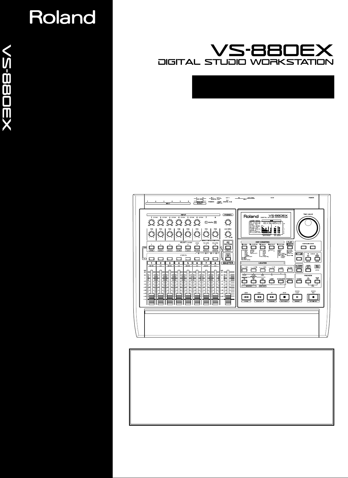
OWNER'S MANUAL
OWNER'S MANUAL
Copyright © 1998 ROLAND CORPORATION
All rights reserved. No part of this publication may be reproduced in any form
without the written permission of ROLAND CORPORATION.
Roland Homepage http://www.rolandcorp.com/
Before using this unit, carefully read the sections entitled: “IMPORTANT SAFETY INSTRUCTIONS” (p. 2), “USING THE UNIT SAFELY” (p.
3, 4), and “IMPORTANT NOTES” (p. 5). These sections provide important
information concerning the proper operation of the unit. Additionally, in
order to feel assured that you have gained a good grasp of every feature
provided by your new unit, Quick Start, Owner’s Manual, and Appendices
should be read in its entirety. The manual should be saved and kept on
hand as a convenient reference.
Page 2
CAUTION
RISK OF ELECTRIC SHOCK
DO NOT OPEN
ATTENTION: RISQUE DE CHOC ELECTRIQUE NE PAS OUVRIR
CAUTION: TO REDUCE THE RISK OF ELECTRIC SHOCK,
DO NOT REMOVE COVER (OR BACK).
NO USER-SERVICEABLE PARTS INSIDE.
REFER SERVICING TO QUALIFIED SERVICE PERSONNEL.
The lightning flash with arrowhead symbol, within an
equilateral triangle, is intended to alert the user to the
presence of uninsulated “dangerous voltage” within the
product’s enclosure that may be of sufficient magnitude to
constitute a risk of electric shock to persons.
The exclamation point within an equilateral triangle is
intended to alert the user to the presence of important
operating and maintenance (servicing) instructions in the
literature accompanying the product.
INSTRUCTIONS PERTAINING TO A RISK OF FIRE, ELECTRIC SHOCK, OR INJURY TO PERSONS.
IMPORTANT SAFETY INSTRUCTIONS
SAVE THESE INSTRUCTIONS
WARNING - When using electric products, basic precautions should always be followed, including the following:
Read all the instructions before using the product.
Do not use this product near water — for example, near a
bathtub, washbowl, kitchen sink, in a wet basement, or near
a swimming pool, or the like.
This product should be used only with a cart or stand that is
recommended by the manufacturer.
This product, either alone or in combination with an amplifier
and headphones or speakers, may be capable of producing
sound levels that could cause permanent hearing loss. Do
not operate for a long period of time at a high volume level
or at a level that is uncomfortable. If you experience any
hearing loss or ringing in the ears, you should consult an
audiologist.
The product should be located so that its location or position
does not interfere with its proper ventilation.
The product should be located away from heat sources such
as radiators, heat registers, or other products that produce
heat.
The product should be connected to a power supply only of
the type described in the operating instructions or as marked
on the product.
1.
2.
3.
4.
5.
6.
7.
8.
9.
10.
11.
A.
B.
C.
D.
E.
The power-supply cord of the product should be unplugged
from the outlet when left unused for a long period of time.
Care should be taken so that objects do not fall and liquids
are not spilled into the enclosure through openings.
The product should be serviced by qualified service
personnel when:
The power-supply cord or the plug has been damaged; or
Objects have fallen, or liquid has been spilled into the
product; or
The product has been exposed to rain; or
The product does not appear to operate normally or
exhibits a marked change in performance; or
The product has been dropped, or the enclosure
damaged.
Do not attempt to service the product beyond that described
in the user-maintenance instructions. All other servicing
should be referred to qualified service personnel.
GROUNDING INSTRUCTIONS
This product must be grounded. If it should malfunction or breakdown, grounding provides a path of least resistance for
electric current to reduce the risk of electric shock.
This product is equipped with a cord having an equipment-grounding conductor and a grounding plug. The plug must be
plugged into an appropriate outlet that is properly installed and grounded in accordance with all local codes and ordinances.
DANGER: Improper connection of the equipment-grounding conductor can result in a risk of electric shock. Check with a
qualified electrician or serviceman if you are in doubt as to whether the product is properly grounded.
Do not modify the plug provided with the product — if it will not fit the outlet, have a proper outlet installed by a qualified
electrician.
For the USA
The product which is equipped with a THREE WIRE GROUNDING TYPE LINE PLUG must be grounded.
WARNING:
IMPORTANT:
As the colours of the wires in the mains lead of this apparatus may not correspond with the coloured markings identifying
the terminals in your plug, proceed as follows:
The wire which is coloured GREEN-AND-YELLOW must be connected to the terminal in the plug which is marked by the
letter E or by the safety earth symbol or coloured GREEN or GREEN-AND-YELLOW.
The wire which is coloured BLUE must be connected to the terminal which is marked with the letter N or coloured BLACK.
The wire which is coloured BROWN must be connected to the terminal which is marked with the letter L or coloured RED.
THIS APPARATUS MUST BE EARTHED
THE WIRES IN THIS MAINS LEAD ARE COLOURED IN ACCORDANCE WITH THE FOLLOWING CODE.
GREEN-AND-YELLOW: EARTH, BLUE: NEUTRAL, BROWN: LIVE
For the U.K.
For the USA
FEDERAL COMMUNICATIONS COMMISSION
RADIO FREQUENCY INTERFERENCE STATEMENT
This equipment has been tested and found to comply with the limits for a Class B digital device, pursuant to Part 15 of the
FCC Rules. These limits are designed to provide reasonable protection against harmful interference in a residential
installation. This equipment generates, uses, and can radiate radio frequency energy and, if not installed and used in
accordance with the instructions, may cause harmful interference to radio communications. However, there is no guarantee
that interference will not occur in a particular installation. If this equipment does cause harmful interference to radio or
television reception, which can be determined by turning the equipment off and on, the user is encouraged to try to correct the
interference by one or more of the following measures:
– Reorient or relocate the receiving antenna.
– Increase the separation between the equipment and receiver.
– Connect the equipment into an outlet on a circuit different from that to which the receiver is connected.
– Consult the dealer or an experienced radio/TV technician for help.
Unauthorized changes or modification to this system can void the users authority to operate this equipment.
This equipment requires shielded interface cables in order to meet FCC class B Limit.
This product complies with the requirements of European Directives EMC 89/336/EEC and LVD 73/23/EEC.
For EU Countries
For Canada
This Class B digital apparatus meets all requirements of the Canadian Interference-Causing Equipment Regulations.
Cet appareil numérique de la classe B respecte toutes les exigences du Règlement sur le matériel brouilleur du Canada.
NOTICE
AVIS
2 191
Page 3
• Before using this unit, make sure to read the instructions below, and the Owner’s Manual.
...........................................................................................................
• Do not open or perform any internal modifications
on the unit. (The only exception would be where
this manual provides specific instructions which
should be followed in order to put in place userinstallable options; see Quick Start p. 49.)
...........................................................................................................
• Make sure you always have the unit placed so it is
level and sure to remain stable. Never place it on
stands that could wobble, or on inclined surfaces.
...........................................................................................................
• Avoid damaging the power cord. Do not bend it
excessively, step on it, place heavy objects on it, etc.
A damaged cord can easily become a shock or fire
hazard. Never use a power cord after it has been
damaged.
...........................................................................................................
• In households with small children, an adult should
provide supervision until the child is capable of following all the rules essential for the safe operation
of the unit.
...........................................................................................................
• Protect the unit from strong impact.
(Do not drop it!)
• Do not force the unit’s power-supply cord to share
an outlet with an unreasonable number of other
devices. Be especially careful when using extension
cords—the total power used by all devices you have
connected to the extension cord’s outlet must never
exceed the power rating (watts/amperes) for the
extension cord. Excessive loads can cause the insulation on the cord to heat up and eventually melt
through.
...........................................................................................................
• Before using the unit in a foreign country, consult
with your retailer, the nearest Roland Service
Center, or an authorized Roland distributor, as listed on the “Information” page.
...........................................................................................................
• Always turn the unit off and unplug the power cord
before attempting installation of the Hard disk drive
unit (HDP88 series: Quick Start p. 49).
USING THE UNIT SAFELY
3
Used for instructions intended to alert
the user to the risk of injury or material
damage should the unit be used
improperly.
* Material damage refers to damage or
other adverse effects caused with
respect to the home and all its
furnishings, as well to domestic
animals or pets.
Used for instructions intended to alert
the user to the risk of death or severe
injury should the unit be used
improperly.
The ● symbol alerts the user to things that must be
carried out. The specific thing that must be done is
indicated by the design contained within the circle. In
the case of the symbol at left, it means that the powercord plug must be unplugged from the outlet.
The symbol alerts the user to important instructions
or warnings.The specific meaning of the symbol is
determined by the design contained within the
triangle. In the case of the symbol at left, it is used for
general cautions, warnings, or alerts to danger.
The symbol alerts the user to items that must never
be carried out (are forbidden). The specific thing that
must not be done is indicated by the design contained
within the circle. In the case of the symbol at left, it
means that the unit must never be disassembled.
Page 4
• Always grasp only the plug on the power-supply
cord when plugging into, or unplugging from, an
outlet or this unit.
...........................................................................................................
• Try to prevent cords and cables from becoming
entangled. Also, all cords and cables should be
placed so they are out of the reach of children.
...........................................................................................................
• Never climb on top of, nor place heavy objects on
the unit.
...........................................................................................................
• Never handle the power cord or its plugs with wet
hands when plugging into, or unplugging from, an
outlet or this unit.
...........................................................................................................
• Before moving the unit, disconnect the power plug
from the outlet, and pull out all cords from external
devices.
...........................................................................................................
• Before cleaning the unit, turn off the power and
unplug the power cord from the outlet (p. 33).
...........................................................................................................
• Whenever you suspect the possibility of lightning in
your area, pull the plug on the power cord out of
the outlet.
...........................................................................................................
• When installing the Hard disk drive unit (HDP88
series), remove only the specified screws (Quick
Start p. 49).
...........................................................................................................
• If you use the optical connector, be sure that the
connector cover you removed is placed out of the
reach of children.
USING THE UNIT SAFELY
4
Page 5

In addition to the items listed under “IMPORTANT
SAFETY INSTRUCTIONS” and “USING THE UNIT
SAFELY” on pages 2–4, please read and observe the
following:
Power Supply
● Do not use this unit on the same power circuit with
any device that will generate line noise (such as an
electric motor or variable lighting system).
● Before connecting this unit to other devices, turn off
the power to all units. This will help prevent malfunctions and/or damage to speakers or other
devices.
Placement
● Using the unit near power amplifiers (or other
equipment containing large power transformers)
may induce hum. To alleviate the problem, change
the orientation of this unit; or move it farther away
from the source of interference.
● This device may interfere with radio and television
reception. Do not use this device in the vicinity of
such receivers.
● Do not expose the unit to direct sunlight, place it
near devices that radiate heat, leave it inside an
enclosed vehicle, or otherwise subject it to temperature extremes. Excessive heat can deform or discolor the unit.
Maintenance
● For everyday cleaning wipe the unit with a soft, dry
cloth or one that has been slightly dampened with
water. To remove stubborn dirt, use a cloth impregnated with a mild, non-abrasive detergent.
Afterwards, be sure to wipe the unit thoroughly
with a soft, dry cloth.
● Never use benzine, thinners, alcohol or solvents of
any kind, to avoid the possibility of discoloration
and/or deformation.
Repairs and Data
● Please be aware that all data contained in the unit’s
memory may be lost when the unit is sent for
repairs. Important data should always be backed up
on a storage device (e.g., hard disk or Zip disk) or
DAT recorder, or written down on paper (when
possible). During repairs, due care is taken to avoid
the loss of data. However, in certain cases (such as
when circuitry related to memory itself is out of
order), we regret that it may not be possible to
restore the data, and Roland assumes no liability
concerning such loss of data.
Additional Precautions
● Please be aware that the contents of memory can be
irretrievably lost as a result of a malfunction, or the
improper operation of the unit. To protect yourself
against the risk of loosing important data, we recommend that you periodically save a backup copy
of important data you have stored in the unit’s
memory on a storage device (e.g., hard disk or Zip
disk), or DAT recorder.
● Unfortunately, it may be impossible to restore the
contents of data that was stored on a storage device
(e.g., hard disk or Zip disk), or DAT recorder once it
has been lost. Roland Corporation assumes no liability concerning such loss of data.
● Use a reasonable amount of care when using the
unit’s buttons, sliders, or other controls; and when
using its jacks and connectors. Rough handling can
lead to malfunctions.
● Never strike or apply strong pressure to the display.
● A small amount of noise may be heard from the dis-
play during normal operation.
● When connecting / disconnecting all cables, grasp
the connector itself—never pull on the cable. This
way you will avoid causing shorts, or damage to the
cable’s internal elements.
● A small amount of heat will radiate from the unit
during normal operation.
● To avoid disturbing your neighbors, try to keep the
unit’s volume at reasonable levels. You may prefer
to use headphones, so you do not need to be concerned about those around you (especially when it
is late at night).
● When you need to transport the unit, package it in
the box (including padding) that it came in, if possible. Otherwise, you will need to use equivalent
packaging materials.
If an internal IDE hard disk (HDP88 series) is
installed, then remove the hard disk. Place the hard
disk in its carton and set this in the specified place
inside the VS-880EX shipping carton. The unit is
now ready to be transported. Moving the VS-880EX
with the hard disk installed may result in loss of
song data or damage to the hard disk.
IMPORTANT NOTES
5
Page 6

Handling the Disk Drive
For details on hard disk handling, refer also to the
instructions that accompanied your hard disk.
● Before performing any of the following actions, be
sure to perform the shutdown procedure. Failure to
do so may result in loss of song data or damage to
the hard disk.
• Turning off the power of the VS-880EX
• Turning off the power of the Zip drive connected
with SCSI connector
• Removing a disk from a Zip drive connected with
SCSI connector
Shutdown (Appendices p. 124)
When the VS-880EX MIDI/DISK indicator or Zip
drive status indicator is lit, it means that data is being
written to or from the hard disk. If you are using a Zip
drive, confirm that this indicator is not lit before
removing disks.
● While using the VS-880EX, be careful not to subject
the unit to vibration or shock, and avoid moving the
unit while the power is turned on.
● Install the unit on a solid, level surface in an area
free from vibration. If the unit must be installed at
an angle, be sure the installation does not exceed
the permissible range.
● Avoid using the unit immediately after it has been
moved to a location with a level of humidity that is
greatly different than its former location. Rapid
changes in the environment can cause condensation
to form inside the drive, which will adversely affect
the operation of the drive and/or damage removable disks. When the unit has been moved, allow it
to become accustomed to the new environment
(allow a few hours) before operating it.
Concerning Copyright
The law prohibits the unauthorized recording, public
performance, broadcast, sale, or distribution etc. of a
work (CD recording, video recording, broadcast, etc.)
whose copyright is owned by a third party.
Roland will take no responsibility for any infringement of copyright that you may commit in using the
VS-880EX.
About SCMS
The VS-880EX does not implement SCMS. This design
decision was made with the intent that SCMS should
not restrict the creation of original compositions which
do not violate copyright law. Do not use this device in
a way which would infringe on copyrights held by
another.
SCMS (Appendices p. 124)
Disclaimer of Liability
Roland will take no responsibility for any direct damages, consequential damages, or any other damages
which may result from your use of the VS-880EX.
These damages may include but are not limited to the
following events which can occur when using the VS880EX.
● Any loss of profit that may occur to you.
● Permanent loss of your music or data.
● Inability to continue using the VS-880EX itself or a
connected device.
About the License Agreement
The VS-880EX and its CD-R capability are designed to
allow you to reproduce material to which you have
copyright, or material which the copyright owner has
granted you permission to copy. Accordingly, reproduction of music CDs or other copyrighted material
without the permission of the copyright owner, other
than for your own personal use and enjoyment (private use) constitutes copyright infringement, which
may incur penalties. Consult a copyright specialist or
special publications for more detailed information on
obtaining such permission from copyright holders.
IMPORTANT NOTES
6
Page 7

Preparations .......................................................................... 12
About the Package Contents ...................................................................................... 12
Main Features ............................................................................................................. 12
Front and Rear Panels .......................................................... 14
Mixer Section .............................................................................................................. 14
Recorder Section ........................................................................................................ 16
Display section ............................................................................................................ 18
Rear Panel .................................................................................................................. 19
Chapter 1 Before You Start (VS-880EX Terminology) ........ 21
Saving and Managing Data ......................................................................................... 21
Managing Disk Contents (Partitioning) ......................................................................... 21
The Location Where a Performance is Recorded (Song) ............................................. 22
Sources, Tracks, and Channels ........................................................................................ 22
About Events ...................................................................................................................... 23
Mixer Section .............................................................................................................. 24
Signal Flow (Buses) ........................................................................................................... 24
Input Mixer ......................................................................................................................... 26
Track Mixer ......................................................................................................................... 27
Effect Return Mixer ........................................................................................................... 27
Switching the Fader Functions ........................................................................................ 28
Master Block ....................................................................................................................... 28
Recorder Section ........................................................................................................ 28
Differences with a Tape-Type MTR ................................................................................ 28
Track Minutes and Recording Time ............................................................................... 29
Auxiliary Tracks for Each Track ...................................................................................... 30
Effects Section ............................................................................................................ 31
About the Effect Expansion Board .................................................................................. 31
Connecting Effects .............................................................................................................31
Chapter 2 Basic Operation ................................................... 32
Before You Begin ........................................................................................................ 32
Turning On the Power ...................................................................................................... 32
If You Have Trouble Understanding Displays or Operations .................................... 32
Before You Finish Operations ..................................................................................... 32
Saving the Performance to Disk (Song Store) ................................................................ 32
Turning Off the Power ...................................................................................................... 33
Restarting ............................................................................................................................ 33
Basic Operations on the VS-880EX ............................................................................ 34
Display Each of the Condition Menus ............................................................................ 34
Selecting Pages Contained in Functions and Settings .................................................. 34
Select the Setting You Want to Change .......................................................................... 35
Change the Settings Values .............................................................................................. 35
Execute the Operation ....................................................................................................... 35
Switching Track Conditions ......................................................................................... 35
Changing the Current Time ......................................................................................... 36
Moving in Frame Units ..................................................................................................... 36
Moving in Measure/Beat Units ....................................................................................... 36
Moving to the Beginning or End of the Performance .................................................. 36
Storing a Time Location .............................................................................................. 36
Using the Locator ............................................................................................................... 37
Using Markers .................................................................................................................... 38
Chapter 3 Multi-Track Recording ......................................... 40
Recording .................................................................................................................... 40
Items Necessary for Multi-Track Recording .................................................................. 40
Creating a New Song (Song New) .................................................................................. 40
CONTENTS
7
Page 8

General Course of the Recording Process ................................................................. 41
Connecting Instruments .............................................................................................. 41
Recording to the Tracks .............................................................................................. 42
Saving a Recorded Performance (Song Store) ........................................................... 43
Recording Over a Portion of a Performance (Punch-In/Punch-Out) ........................... 44
Using the RECORD Button (Manual Punch-In 1) ......................................................... 44
Using the Foot switch (Manual Punch-In 2) .................................................................. 44
Specifying Beforehand the Location for Rerecording (Auto Punch-In) .................... 45
Repeatedly Recording Over the Same Area (Loop Recording) .................................. 47
Recording to Other Tracks (Overdubbing) .................................................................. 49
Recording on V-Track 2 .................................................................................................... 49
Using Effects ............................................................................................................... 50
Applying Effects to the Playback .................................................................................... 50
Applying Effects While Recording (Send/Return) ...................................................... 51
Applying Effects While Recording (Insert) .................................................................... 52
Recording Digital Signals ............................................................................................ 55
Items Necessary for Digital Recording ........................................................................... 55
Make the Digital Connections ......................................................................................... 55
Match the Sample Rates .................................................................................................... 55
Select the Master Clock ..................................................................................................... 56
Select an Input Source ....................................................................................................... 56
Adjusting the Tone (Equalizer) .................................................................................... 57
Using the 3-Band Equalizer .............................................................................................. 57
Adjusting the Equalizer .................................................................................................... 57
Combining the Contents of Tracks (Track Bouncing) ................................................. 60
Applying Reverb While Track Bouncing ....................................................................... 61
Creating a Master Tape .............................................................................................. 63
To Record to a Cassette Tape ........................................................................................... 63
Recording with DAT and MD Recorders ....................................................................... 63
Protecting Songs (Song Protect) ................................................................................. 64
Protecting Performances ................................................................................................... 65
To Remove Song Protect ................................................................................................... 65
Selecting a Song (Song Select) .................................................................................. 65
Chapter 4 Using the Internal Effects ................................... 66
Composition of the Effects .......................................................................................... 66
Connecting the Effects ................................................................................................ 66
Changing the Source Sound Itself (Insert) ..................................................................... 66
Inserting with Input and Track Channels ...................................................................... 67
Inserting an Effect into the Master Block ....................................................................... 67
Adding the Sound with the Effect Applied to the Direct Sound (Send/Return) ..... 68
Selecting Effects (Patch) ............................................................................................. 70
Creating New Effects Sounds ..................................................................................... 71
When Saving to User Patches .......................................................................................... 72
When Storing to a Scene ................................................................................................... 72
Chapter 5 Storing Mixer Settings ......................................... 73
Recording the Current Condition of the Mixer (Scene) ............................................... 73
Making Mixer Settings Automatically(EZ Routing) ...................................................... 74
Recalling Recording Settings (Recording/Template) .................................................. 75
Recalling Track Bouncing Settings (Bouncing/Template) .......................................... 75
Recalling Mixdown Settings (Mixdown/Template) .................................................... 76
Storing Recording Settings (Recording/Step Edit) ...................................................... 77
Storing Track Bouncing Settings (Bouncing/Step Edit) .............................................. 81
Storing Mixdown Settings (Mixdown/Step Edit) ........................................................ 84
Saving the Current Routing (User Routing) .................................................................. 87
Recalling User Routing ..................................................................................................... 87
Deleting User Routings ..................................................................................................... 87
CONTENTS
8
Page 9

Chapter 6 Editing a Recorded Performance (Track Editing) ... 88
About Editing Operations ............................................................................................ 88
Track Edit .................................................................................................................... 88
About the Bar Display ....................................................................................................... 88
Repeating Performance Data (Track Copy) ................................................................... 89
Moving Performance Data (Track Move) ...................................................................... 91
Exchanging Performance Data Between Tracks (Track Exchange) ............................ 92
Inserting a Blank Space Into Performance Data (Track Insert) ................................... 93
Deleting Performance Data (Track Cut) ......................................................................... 94
Erasing Performance Data (Track Erase) ....................................................................... 95
Modifying the Playback Time of the Performance Data
(Time Compression/Expansion) ..... 96
Chapter 7 Use with a Zip Drive ............................................ 99
Before You Use a Zip Drive ........................................................................................ 99
Handling the Zip Drive .................................................................................................... 99
Handling Zip Disks ........................................................................................................... 99
Connecting the Zip Drive ............................................................................................. 99
Initializing the Disk (Drive Initialize) ........................................................................... 100
Checking Disk Reliability ............................................................................................... 101
Saving Performance Data to a Zip Drive (Song Copy) ............................................. 102
Saving a Song to a Single Disk (Playable) ................................................................ 103
To Load Data from Disks (Drive Select) .................................................................... 104
When You Cannot Save a Song to a Single Disk (Archives) .................................... 105
Saving to Disks (Store) .................................................................................................... 105
Loading Data From Disks (Extract) .............................................................................. 106
About power-save mode ........................................................................................... 106
Chapter 8 Use with a CD-RW Drive .................................... 107
Before You Use a CD-RW Drive ............................................................................... 107
Handling the CD-RW Drive ........................................................................................... 107
Handling CD-RW Discs .................................................................................................. 107
Connecting the CD-RW Drive ................................................................................... 107
Creating an Audio CD ............................................................................................... 108
Items Necessary for Creating an Audio CD ................................................................ 108
Creating a Master Data ................................................................................................... 108
Writing Songs to CD-R Discs ......................................................................................... 109
Auditioning (Test Listening) Songs Written to CDs (CD Player Function) ............ 110
Writing Additional Songs to the Disc ........................................................................... 111
Arranging and Writing Multiple Songs to Disc .......................................................... 111
Writing the Song Data (Finalize) ................................................................................... 112
Arranging and Writing Songs and Song Data ............................................................ 113
Saving Songs to CD-RW Discs (CD-R Backup) ....................................................... 113
Items Necessary for CD-R Backup ................................................................................ 114
Saving Songs to CD-RW Discs ....................................................................................... 114
Loading Songs From CD-RW Discs .............................................................................. 115
How to Erase the Data in the CD-RW Disc ................................................................. 115
Chapter 9 Use with MIDI Devices ....................................... 116
Synchronizing with MIDI Sequencers ....................................................................... 116
Items Necessary for Synchronization ........................................................................... 116
Master and Slave .............................................................................................................. 116
Using MTC ....................................................................................................................... 116
Synchronization with the VS-880EX as the Reference (Master) ............................... 117
Synchronization with the MIDI Sequencer as the Reference (Slave) ....................... 118
Synchronizing with an External MIDI Device ............................................................ 119
Using the Sync Track (Master) ....................................................................................... 119
Using the Tempo Map (Master) .................................................................................... 121
CONTENTS
9
Page 10

Various Operations Related to Synchronized Operation .......................................... 123
Use with a MIDI Controller ........................................................................................ 126
Switching Track Status ................................................................................................... 126
Switching Scenes .............................................................................................................. 127
Switching Effects .............................................................................................................. 127
Adjusting Effects .............................................................................................................. 127
Chapter 10 Use with a DAT Recorder (DAT Backup) ........ 128
Before Backing Up with DAT ..................................................................................... 128
Items Necessary for DAT Backup ............................................................................. 128
About the Devices Used in DAT Backup ..................................................................... 128
Saving Song Data to a DAT Recorder (Backup) ....................................................... 129
Loading Performance Data from a DAT Recorder (Recover) ................................... 131
When Canceling the Recover Operation ...................................................................... 132
Checking Names of Saved Performance Data (Name) ............................................ 133
Checking the Recording Condition of Saved Performance Data (Verify) .................. 134
Chapter 11 Compatibility .................................................... 136
Disk Compatibility ...................................................................................................... 136
VS-880 → VS-880EX ........................................................................................................ 136
VS-880EX → VS-880 ........................................................................................................ 136
VS-1680 → VS-880EX ...................................................................................................... 136
VS-880EX → VS-1680 ...................................................................................................... 137
VS-840 ↔ VS-880EX ........................................................................................................ 137
Song Data Compatibility ............................................................................................ 137
Loading VS-880 Performance Data into the VS-880EX (Song Import) .................... 137
Converting VS-880EX Song Data for Use with the VS-880 (Song Export) .............. 138
Chapter 12 Other Convenient Functions .......................... 140
Previewing Techniques (Preview) ............................................................................. 140
Using [TO] [FROM] ......................................................................................................... 140
Using [SCRUB] ................................................................................................................. 141
Recalling a Specific Location (Jump) ........................................................................ 142
Recording Mixer Settings (Auto Mix) ......................................................................... 142
Preparations for Auto Mix ............................................................................................. 143
Recording the Mixer Settings, Method 1 (Snapshot) .................................................. 143
Recording the Mixer Settings, Method 2 (Gradation) ................................................ 144
Recording Fader Operations (Realtime) ....................................................................... 144
If You Don’t Want to Record Fader Settings (Mask Fader) ....................................... 145
Playing Back the Auto Mix ............................................................................................. 145
Disabling Auto Mix Only on Specified Channels ....................................................... 145
Disabling Auto Mix on All Channels ........................................................................... 146
Undoing Recordings and Edits (Undo) ...................................................................... 146
Recording and Editing Operations Which Can Be Undone (Undo)......................... 147
Canceling the Last-Performed Undo (Redo) ............................................................... 147
Canceling Only the Very Last-Performed Operation ................................................. 147
Listening Only to a Specific Channel (Solo/Mute) ..................................................... 148
Listening Only to a Specific Channel ............................................................................ 148
Muting Only to a Specific Channel ............................................................................... 148
Simultaneously Adjusting a Stereo Source (Channel Link) ....................................... 149
Adjusting the Faders ....................................................................................................... 149
Adjusting the Pan ............................................................................................................ 150
Linking Only the Faders (Fader Link) .......................................................................... 151
Mixing In a Stereo Source (Stereo In) ....................................................................... 152
Changing the Pitch During Playback (Vari-Pitch) ...................................................... 152
Record/Playback Tracks When Using Vari-Pitch ...................................................... 153
Directly Inputting Numeric Characters ...................................................................... 153
Selecting the Method for Numeric Input ..................................................................... 153
CONTENTS
10
Page 11

Sounding the Metronome .......................................................................................... 154
Using an External MIDI Sound Source to Play the Metronome ............................... 155
When the Disk Has Little Remaining Space ............................................................. 156
Deleting Only Unneeded Performance Data (Song Optimize) ................................. 156
Deleting One Song of Performance Data (Song Erase) .............................................. 157
Changing the Name of Performance Data (Song Name) .......................................... 157
Adjusting the Levels for Each Track .......................................................................... 157
When Using Balanced Inputs .................................................................................... 158
Determining Output ................................................................................................... 158
MASTER Jacks ................................................................................................................. 158
AUX Jacks ......................................................................................................................... 159
DIGITAL OUT Connectors ............................................................................................ 159
DIRECT OUT ................................................................................................................... 160
Confirming That a Drive is Not Damaged (Drive Check) .......................................... 160
Chapter 13 Making Global Settings and Checking Conditions .. 163
Switching the Display Content .................................................................................. 163
Pre Level ........................................................................................................................... 163
Post Level .......................................................................................................................... 163
Play List ............................................................................................................................. 163
Feder/Pan ......................................................................................................................... 163
Checking the Size of a Recorded Performance ........................................................ 164
System Settings for Each Song ................................................................................ 164
Having the Volume Change as Soon as the Faders are Moved ................................ 164
Holding Level Meter Peaks ............................................................................................ 164
Checking the Remaining Disk Space ............................................................................ 165
When Using the Foot Switch .......................................................................................... 165
Overall Settings for the VS-880EX ............................................................................ 166
Holding the function of [SHIFT] (Shift Lock) .............................................................. 166
Displaying Measures and Beats .................................................................................... 166
Adjusting the Button Sensitivity ................................................................................... 167
Changing the VS-880EX’s SCSI ID Number ................................................................ 167
When There Is No Hard Disk Installed ........................................................................ 167
Changing at the Level at Which the Peak Indicator Lights ....................................... 168
Overall Settings for Playback and Recording ............................................................ 168
Constantly Monitoring the Input Source ..................................................................... 168
Stopping Automatically .................................................................................................. 168
If Noise Between Segments is Obtrusive ..................................................................... 169
Resetting Mixer and System Settings to Their Original State ................................... 169
Chapter 14 Takein Advantages of the VS-880EX (idea and examples) 170
Synchronizing the Operations of Two VS-880EX Units ............................................ 170
Settings for the Master VS-880EX .................................................................................. 170
Settings for the Slave VS-880EX .................................................................................... 172
Synchronizing with Cakewalk Pro Audio (MMC) ....................................................... 173
Settings for the VS-880EX ............................................................................................... 174
Settings for Cakewalk Pro Audio .................................................................................. 175
Making Digital Connections with Cakewalk ............................................................... 177
Using an External MIDI Device to Adjust the Mixer (Compu Mix) ............................. 180
The Correspondence Between MIDI Channels and Controller Numbers .............. 181
Preparations for Compu Mix ......................................................................................... 182
Recording with Compu Mix .......................................................................................... 183
To Have the Fader Movements Ignored ...................................................................... 183
Synchronizing with Video Equipment ........................................................................ 184
Using External Effects Devices ................................................................................. 185
CONTENTS
11
Page 12

About the Package Contents
The following items are included with the VS-880EX.
Please check to make sure you have all the items.
• VS-880EX
• AC cord
• Quick Start
• Owner’s Manual (this manual)
• Appendices
Main Features
The Latest in Compact Home Studio
Environments
The VS-880EX retains all of the features of Roland’s
VS-880 workstation; a revolution in the world of the
home studio, with the disk recorder, digital mixer, and
multi effects systematically and more organically integrated. From when you start picking mics to when
you actually record to mixdown, adding effects, and
on to creating the master data for playing through a
PA or mastering on a CD, you can get a handle on
every aspect of the recording process with the VS880EX in your home studio.
Disk Recorder Section
The digital disk recorder section provides eight playback tracks, and allows eight tracks to be recorded
simultaneously. Each track has eight supplementary
tracks (V-tracks), and each song can have two sets of
these 64 tracks (8 tracks x 8 V-tracks). This means that
a song can have a total of 128 tracks (64 V-tracks x 2
banks), giving you flexibility when you need to record
multiple takes, or need a location for temporary storage for editing.
You can instantly find the location of sections in a
song you want to hear repeatedly or places that you
wish to record over (Locator) by placing marks at such
points (Marker). These Markers are recalled by simple
procedure, and you will never wait for any rewinding
or fast-forwarding time.
The VS-880EX uses “non-destructive editing.” This
allows you to cancel and recover up to 999 previous
recording and editing operations (Undo/Redo).
Digital Mixer Section
You can store all mixer settings, including fader levels,
pan, and effects. Stored settings can be recalled very
simply, making it convenient in adjusting balances
during mixdown and comparing mixes with effects.
Changes in settings over time, such as fader levels and
pan, can also be stored (Auto Mix), so you can realize
easy fade-ins and fade-outs in your mixes.
You can easily make the most appropriate mixer condition settings, including those for recording, track
bouncing, and mixdown (EZ Routing).
Effects Section
A Effect is built in. This allows you to use up to two
stereo effects when the VS-880 EX is used by itself.
The effect provides not only basic effects such as
reverb and delay, but also effects ideal for vocals and
guitar (such as guitar amp simulator) and even special
effects such as RSS. The way in which each of these
effects are organized by the 34 “algorithms” so that
you can create new sounds easily.
The effect provides 210 read only effects setting (Preset
Patches) which designed for various uses. In addition,
the effect provides 100 read and write effects setting
(User Patches) for changing and saving that contents.
You can instantly switch between a variety of effects
simply by selecting a patch.
Simple Operation
The VS-880EX can be operated as easily as conventional multi-track recorders. You will be able to enjoy the
advantages of home studio from the day that you purchase it.
The custom LCD screen provides visual confirmation
of many settings at once. In particular, the bar display
provides a graphical indication of the level meter, pan
and fader settings, and the track record status.
The LCD screen is backlit and inclined, so it is easy to
read when used on stage or wherever high visibility is
required.
Preparations
12
Page 13

Connectivity
There are six sets of balanced input jacks, handling a
wide input sensitivity range, from line level (+4 dBu)
to mic level (-50 dBu).
Besides the RCA phono type (stereo) MASTER jacks,
the (mono) AUX A and AUX B jacks are provided.
The VS-880EX provides both coaxial and optical digital I/O connectors. With these, you can make digital
connections with popular consumer electronic devices
such as CD players, DAT recorders, MD recorders,
and so on.
A SCSI connector (DB-25 type) is also provided, allowing you to connect to external SCSI devices such as the
Zip drive and the CD-R drive.
MIDI IN and MIDI OUT/THRU connectors are also
provided. You can synchronize the VS-880EX with an
external MIDI sequencer, use the MIDI sequencer to
control the VS-880EX’s mixer, sound an external MIDI
sound generator with the metronome, and more.
Besides tracks for recording audio signals, the VS880EX has sync track for storing MIDI clock message.
You can even synchronize MIDI sequencers that are
not compatible with MTC (MIDI Time Code) or MMC
(MIDI Machine Control).
Substantial Options
Internal Hard Disk (desinated by Roland):
An internal 2.5-inch IDE hard disk. Having this internal hard disk installed makes the VS-880EX system
compact and easy to transport. Furthermore, there is
no need to make complex settings and no problems
with faulty connections (unlike those which could
occur when an external disk is used). We recommend
that you install an internal hard disk when using the
VS-880EX.
* For simultaneous recording or playback of a number of
tracks, for getting more out of the available hard disk
space, and in order to get the fullest performance in general from the VS-880EX, we recommend using the 2.1
GB or larger Hard Disk.
CD-R Drive (designated by Roland):
A CD-R drive connected with a SCSI connector. With
this drive, you can write songs created on the VS880EX as well as create your own original audio CDs.
Additionally, you can use it for backing up songs to
CD-R discs.
SI-80S:
This is a video/MIDI sync interface for connection to
the MIDI connector. VS-880EX operations such as
play/stop/forward can be synchronized from a video
device with a LANC connector.
Preparations
13
Page 14
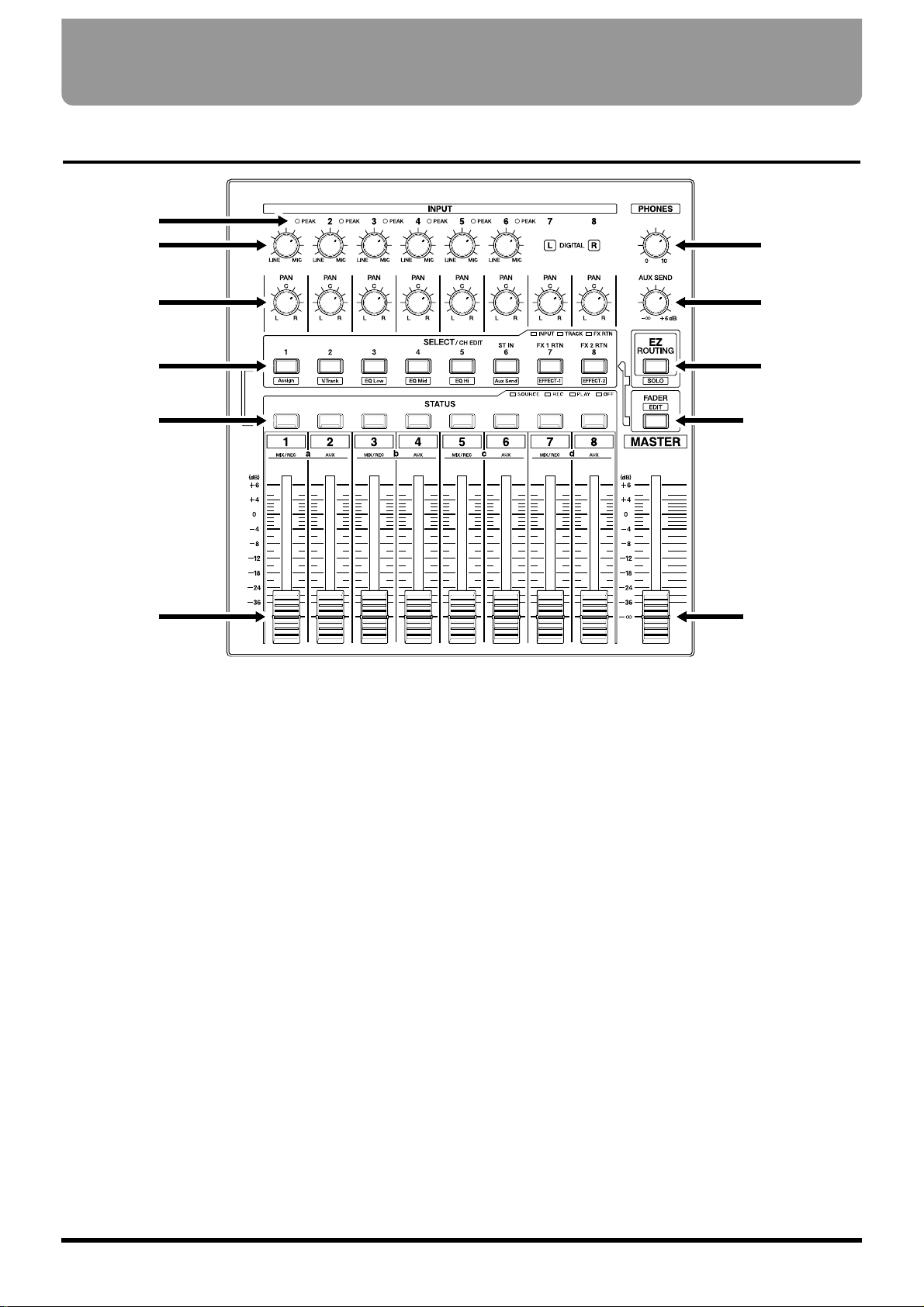
Mixer Section
1
2
3
4
5
6
7
8
9
10
11
Front and Rear Panels
14
1. PEAK Indicators
These indicators allow you to confirm the sound level
input at the input jacks (1–6). They help you to determine the correct input level when adjusting the
INPUT knobs. You will need to specify the level at
which the indicators light beforehand (p. 61). The indicators are set at the factory to -6 dB.
2. INPUT Knobs
These knobs adjust the sensitivity of the input jacks
(1–6). Turn a knob fully to the right for mic level (-50
dBu), and fully to the left for line level (+4 dBu).
3. PAN Knobs
These knobs adjust the pan (location in the stereo output) of each channel.
4. SELECT/CH EDIT (Select/Channel
Edit) buttons
Use these buttons when you wish to make settings for
a mixer channel. The names of the parameter groups
that can be set for each channel are printed below CH
EDIT. To directly specify a particular group, you can
hold down [SHIFT] and press the button for that
group name.
When editing a song, use these buttons to select tracks
for editing.
Page 15

5. STATUS Buttons
These buttons switch the status of each track. The current status is shown by the button indicator.
SOURCE (orange):
The input source or track assigned to the channel is
being output.
REC (blinking red):
Recording is selected for the track assigned to the
channel. During playback, the track data is normally output.
REC (blinking red and orange):
Recording is selected for the track assigned to the
channel. During playback, you will be able to listen
to the source.
PLAY (green):
The track assigned to the channel will playback.
OFF (off):
The channel is muted (silent).
When pressed in combination with the SELECT/CH
EDIT button, this selects the source or track to be
assigned to a track for recording.
6. Channel Faders
Use these faders to adjust the volume level of each
channel or track.
7. PHONES Knob
This knob adjusts the volume of the headphones.
8. AUX SEND knob
This knob adjusts the output level of the AUX SEND
jacks.
9. EZ ROUTING/SOLO Button
This button opens the EZ Routing screen.
In conjunction with [SHIFT], this switches the Solo
function on/off.
10. FADER/EDIT Button
Pressing this button alternately assigns each channel’s
input mixer, track mixer and effect return mixer to the
fader for that channel. The button indicator shows the
current status.
INPUT (orange): Input Mixer
TRACK (green): Track Mixer
RETURN (red): Effect Return Mixer
In conjunction with [SHIFT], this accesses the Master
Block setting page.
11. Master Fader
Use this fader to adjust the overall output level.
Preparations
15
Page 16
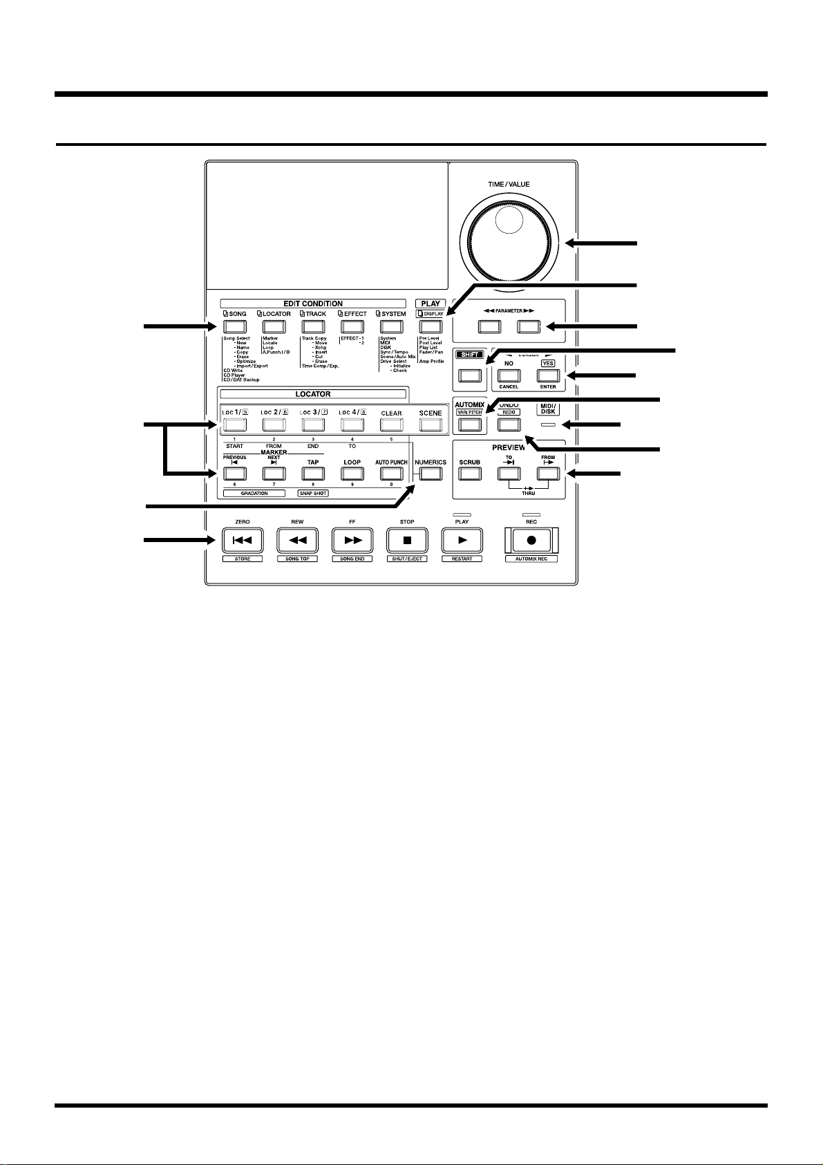
Recorder Section
1
3
4
2
5
7
9
13
11
6
8
10
12
Preparations
16
1. EDIT CONDITION Buttons
The functions and parameters of the VS-880EX are
organized within these buttons. To use a desired operation, press the appropriate button.
2. LOCATOR Button
Pressing this button allows you to store or recall
Locators and Markers or to store or recall Scenes (the
mixer settings).
[LOC1/5]–[LOC4/8]: This button selects Locators
and Scenes.
[CLEAR]: This button deletes Locators,
Markers, and Scenes.
[SCENE]: This is pressed when storing,
recalling, and deleting Scenes.
[PREVIOUS]: This button recalls the previous
Marker.
[NEXT]: This button recalls the next Marker.
[TAP]: This button is pressed to set
Markers.
[LOOP]:
This button turns Loop Recording on
and off. Pressed with the
[LOC1/5]–[LOC4/8] buttons, it specifies the range to be recorded in Loop
Recording.
[AUTO PUNCH]: This button turns Auto
Punch-In Recording on and
off. Pressed with the
[LOC1/5]–[LOC4/8] buttons, it specifies the range to
be recorded in Auto PunchIn Recording.
3. NUMERICS Button
Press this when you want to use the LOCATOR button
for 10-key entry of Western numerals.
Page 17

4. Transport Control Buttons
These buttons are used to operate the recorder.
[ZERO]: This returns the current time to
“00h00m00s00” (zero return).
[REW]: The current time is moved back only
while this button is held down. This
corresponds to the rewind button on a
tape recorder.
[FF]: While the button is held down, the
current time is moved forward. This
corresponds to the fast-forward button
on a tape recorder.
[STOP]: Stops recording or playback of the
song.
[PLAY]: Starts recording or playback from the
current time.
[REC]: Press this button to record a song.
5. TIME/VALUE Dial
In normal (playback) status, this dial adjusts the time
of playback.
This is used to change the settings values for each
parameter when settings are changed.
6. PLAY (DISPLAY) Button
Press this button to return to the screen that appears
when the VS-880EX is turned on (normal playback status).
In conjunction with [SHIFT], this switches the item
shown in the bar display.
7. PARAMETER Buttons
Use these buttons to switch the parameter display.
8. SHIFT Button
This button is pressed in conjunction with other buttons to access additional functions of those buttons.
9. CURSOR Buttons
Normally (i.e. in Play Condition), this dial is used to
move the current time. When making settings (i.e. in
Edit Condition), this dial is used to modify parameter
values.
When a YES/NO response is required during an operation, use these button to reply.
[NO (CANCEL)]: This is pressed to cancel the cur-
rent operation or exit the current screen.
[YES (ENTER)]: This is pressed to execute the
current operation or select the
current screen.
10. AUTOMIX (VARI PITCH) Button
This button switches the Auto Mix function on and off.
The button indicator lights when Auto Mix is on.
In conjunction with [SHIFT], this switches the Varipitch function on/off.
11. MIDI/DISK Indicator
This indicator lights green when MIDI messages are
being received, and red when data is being written or
read on the disk drive. If both of these are occurring,
the indicator lights orange.
12. UNDO (REDO) Button
Press this button to cancel a recording or editing step
that you have made (Undo function). Pressed with
[SHIFT], this button cancels the last performed Undo
function (Redo function).
13. PREVIEW Button
Press this button to use the Preview function that
plays back a specific length before and after the current location.
Preparations
17
Page 18
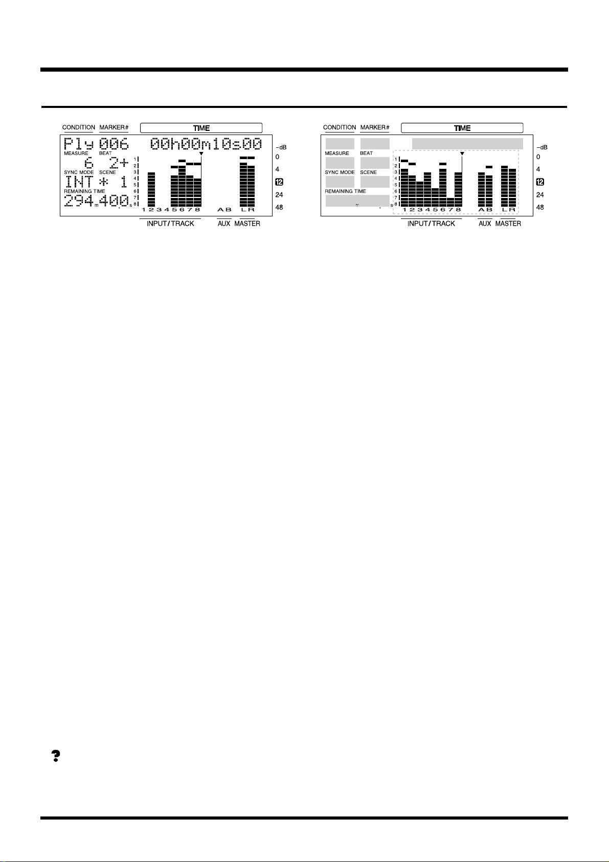
Display section
1 2 3
9
4 5
6
8
7
Preparations
18
1. CONDITION
This indicates the current condition.
PLY: Normal status (Play condition).
INn: Change the input mixer settings
(n=1–8, a–d).
TRn: Change the track mixer settings
(n=1–8 to a–d).
RTN: Change the return mixer settings.
MST: Change the master block settings.
SNG: Song edit
LOC: Locator edit
TRK: Track edit
FX: Effect edit
SYS: System edit
* If Song Protect (p.64) is turned on, the Play Condition
display will be “Ply.”
* The input/track mixer display will indicate 1–8 for chan-
nels whose Channel Link is OFF, and a–d for channels
which are turned ON.
2. MARKER # (marker number)
This shows the marker number for the current time. If
a mark point has not been assigned to the current
time, the closest marker number located before the
current time will be shown.
3. TIME
The current time of the song is displayed as SMPTE
time code.
SMPTE Time Code (Appendices p. 124)
4. MEASURE
This shows the current measure of the song.
5. BEAT
This shows the current beat of the song.
6. SYNC MODE
This indicates the current sync mode (method of synchronization).
7. SCENE
This shows the currently used scene number (mixer
setting). An asterisk “✱” shown at the beginning of the
scene number indicates that the current mixer settings
have been modified since the scene was recalled.
8. REMAINING TIME
This shows the remaining length of time available for
recording.
9. Bar display
In normal condition, the item selected by [DISPLAY
(PLAY)] are shown graphically. While you are making
a setting, data for the setting being made is displayed
graphically.
Page 19
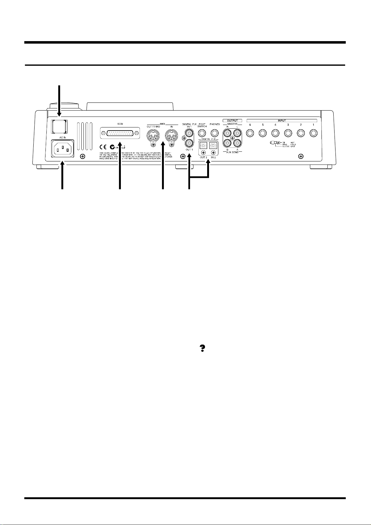
Rear Panel
1
2 3 4 5
Preparations
19
1. POWER Switch
This switch turns power of the VS-880EX on and off.
2. AC IN (AC Inlet)
Connect the included power cable here.
3. SCSI Connector
This is a DB-25 type SCSI connector for connecting
disk drives such as a Zip disk drive or a CD-R drive.
4. MIDI Connectors (IN, OUT/THRU)
External MIDI devices (MIDI controllers, MIDI
sequencers, etc.) can be connected here.
IN: This connector receives MIDI mes-
sages. Connect it to the MIDI OUT
connector of the external MIDI
device.
OUT/THRU: This connector can be used either as
a MIDI OUT or as a MIDI THRU
connector. With the factory settings,
it will function as a MIDI OUT connector, which means it is set to
transmit MIDI messages.
5. DIGITAL Connectors
The VS-880EX features both coaxial and optical digital
I/O connectors (conforming to S/P DIF).
IN: This inputs a digital audio signal
(stereo). You can select either the
coaxial input connection or the optical connection.
OUT: This outputs a digital audio signal
(stereo). Here you can use both the
coaxial connector and the optical
connector simultaneously, and each
can carry a different signal.
S/P DIF (Appendices p. 124)
* To record a digital audio signal, it is not sufficient to sim-
ply connect a digital audio device to the DIGITAL IN
connector. When inputting a digital audio signal, refer to
“Recording Digital Signals” (p. 55).
* It is not able to input or output analog audio signals.
Page 20
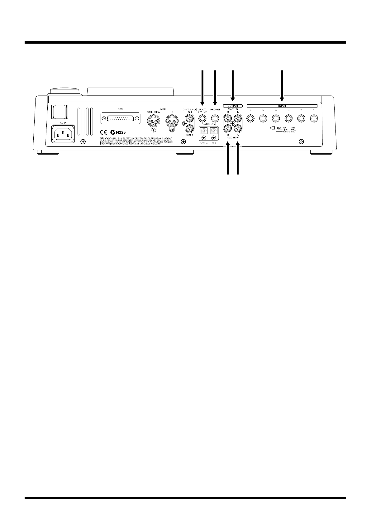
6 7 118
9 10
Preparations
20
6. FOOT SWITCH Jack
An optional foot switch (such as the DP-2 or the BOSS
FS-5U) can be connected here when you want to control recorder operations, mark point settings, and
punch in/out operations, and so on with a foot switch.
With the factory settings, a foot switch is set to start
and stop the recorder.
7. PHONES Jack
An optional set of headphones can be connected here.
The PHONES jack outputs the same sound as the
MONITOR jack.
8. MASTER Jacks (L, R)
9. AUX SEND Jack A
10. AUX SEND Jack B
These are output jacks for analog audio signals (RCA
phono type).
With the factory settings, all signals are output from
the MASTER OUT jacks, and there is no output from
the AUX (A and B) SEND jacks. The output is determined by the block settings of the mixer’s master sec-
tion and the settings of each channel.
11. INPUT Jacks (1–6)
These are input jacks for analog audio signals. These
are balanced phone jacks, the input sensitivity of each
jack is adjusted by the INPUT knobs on the top panel.
Page 21
This chapter explains basic concepts, internal structure, and basic operation that you will need to know in
order to operate the VS-880EX. Please read this chapter thoroughly to gain a better understanding of the
VS-880EX.
Saving and Managing Data
Managing Disk Contents (Partitioning)
The VS-880EX saves all of the data such as — performance data, mixing data, system data, etc. — on the
disk drive. Thus, it cannot operate without either having an internal disk or being connected to a Zip drive
with a SCSI connector. Furthermore, the hard disk or
Zip drive used by the VS-880EX cannot be used by
another device.
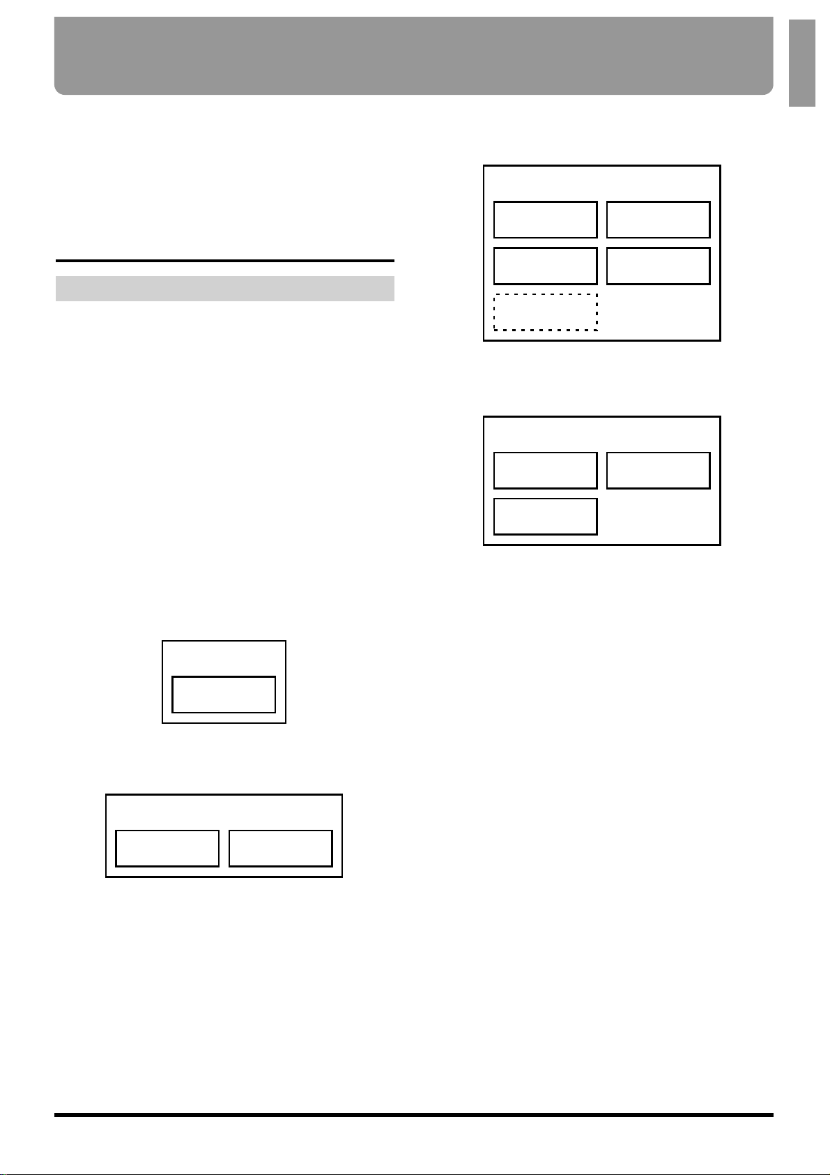
The VS-880EX is able to manage which 500 MB or 1000
MB of disk space at once. If you use a disk drive with a
capacity that is larger than this, you will need to
divide it into two or more.
Each of these area is refered as the “partition.” Up to 4
partitions can be created in one disk drive. For creating songs in a enough space, we recommend you to
set the partitions to 1000 MB.
Ex. 1: When the disk drive is 810 MB, and the parti-
tion size is 1000 MB.
Ex. 2: When the disk drive is 1.4 GB, and the parti-
tion size is 1000 MB.
Ex. 3: When the disk drive is 2.1 GB, and the parti-
tion size is 500 MB.
Ex. 4: When the disk drive is 2.1 GB, and the parti-
tion size is 1000 MB.
Each partition on the VS-880EX’s disk drive is treated
as an independent drive, with each partition automatically given a partition number (0–3). When a single
hard disk has multiple partitions, you can specify
which partition of which drive will be used. This disk
drive partition currently used is referred to as the cur-
rent drive.
Partition
(810MB)
Disk Drive
(810MB)
Partition 0
(1000MB)
Partition 1
(400MB)
Disk Drive
(1.4GB)
Partition 2
(500MB)
unusable
(100MB)
Partition 0
(500MB)
Partition 3
(500MB)
Partition 1
(500MB)
Disk Drive
(2.1GB)
Partition 2
(100MB)
Partition 0
(1000MB)
Partition 1
(1000MB)
Disk Drive
(2.1GB)
Chapter 1 Before You Start (VS-880EX Terminology)
21
Chapter 1
Page 22

Specify the Disk Which will be Used
for Recording/Playback (Drive Select)
1. Press [SYSTEM] several times until “SYS Drive
Select” appears in the display.
2. Press [YES].
3. Use the TIME/VALUE dial to select the desired
disk drive. The internal hard disk is shown as
“IDE:*” and external disk drives are shown as
“SC0:*–SC7:*” (the number is the SCSI ID number).
The number following each disk drive name is the
partition number. For example if you wish to select
internal hard disk partition 1, you would select
“IDE:1.”
4. Press [YES].
A confirmation message appears on the screen.
5. Press [YES].
“STORE Current?” (Store the current song?) appears
in the display.
6. If you wish to save the current song, press [YES]; if
not, then press [NO]. If you have selected a demo
song, then press [NO].
7. After you have switched the current drive, return
to Play condition.
* If you wish to use hard disks or song data on both the VS-
880EX and the VS-880/840/1680, because of factors such
as differing partition sizes and numbers of tracks, there
will be limitations as to what you can do. For more
detailed information, please see “Compatibility” (p. 136).
* The VS-880EX accepts installation of Internal hard disks
(desinated by Roland). For simultaneous recording or
playback of a number of tracks, for getting more out of the
available hard disk space, and in order to get the fullest
performance in general from the VS-880EX, we recom-
mend using the 2.1 GB or larger Internal Hard
Disk.
The Location Where a Performance is
Recorded (Song)
The location where a performance data is recorded is
refered to as the song. For example on a cassette MTR,
this would correspond to cassette tape. Up to 200
songs can be created in each partition. Normally, you
should set the partition size at 1000 MB. When dealing
with large numbers of songs at the same time, setting
the partition size to 500 MB is recommended. The song
currently being recorded, played back, or edited is
referred to as the current song. Following data are
included in a song.
• All data recorded on V-tracks
• MIDI clocks of the sync track
• Points specified within songs (locator, marker,
punch-in/out points, loop-in/out points) (p. 36)
• Scenes (mixer settings)
• Vari Pitch settings (p. 152)
• System settings (system, MIDI, disk, sync, Scene)
(p. 164)
• Effect settings
• Auto Mix Data
Sources, Tracks, and Channels
On the VS-880EX, the recorder section and mixer section use term sources, tracks, and channels. These
terms may appear similar to each other, and will be
confusing unless their differences are clarified.
Source: A signal which is input to the mixer sec-
tion or recorded in the recorder section.
On the VS-880EX, this term refers in particular to the signals of the analog input
jacks (1–6) and the digital in connector.
Track: A signal that is being input to or output
from the recorder section. It also refers to
the location of a signal that is being
recorded onto or played back from the
hard disk.
Channel: A signal that is being input to or output
from the mixer section. This term refers in
particular to the faders and buttons of the
mixer section on the top panel.
Chapter 1 Before You Start (VS-880EX Terminology)
22
Page 23

About Events
The smallest unit of memory used by the VS-880EX to
store recorded results on disk is called an event. A
newly created song is provided approximately 12,800
events.
For each track, one recording pass uses two events.
Operations such as punch-in/out or track copy also
use up events. The number of events that are used up
will fluctuate in a complex way. For example, auto
mix (p. 142) uses up 5 events for each Marker.
Even when your disk has ample free space, one song
can use up all the available events, in which case no
more data could be recorded to the song.
Remaining number of Events can be saved with the
following procedures. Please try the most appropriate
one with your situation.
● Execute Song Store (p. 32)
Please Execute Song Store if in UNDO condition
([UNDO] indicator is lit.). Events served for REDO
will be released. But please note that you cannot cancel (REDO) the last UNDO if you once execute STORE.
● Execute Song Optimize (p. 156)
Please execute Song Optimize if you have done a lot of
Punch In recording. Events served for unnecessary
audio data will be released. But please note that you
can only do single level UNDO.
● Erase AutoMix data (p. 146)
If you have recorded AutoMix data, erase unnecessary
data. Events served for unnecessary AutoMix data will
be released.
Chapter 1 Before You Start (VS-880EX Terminology)
23
Chapter 1
Page 24
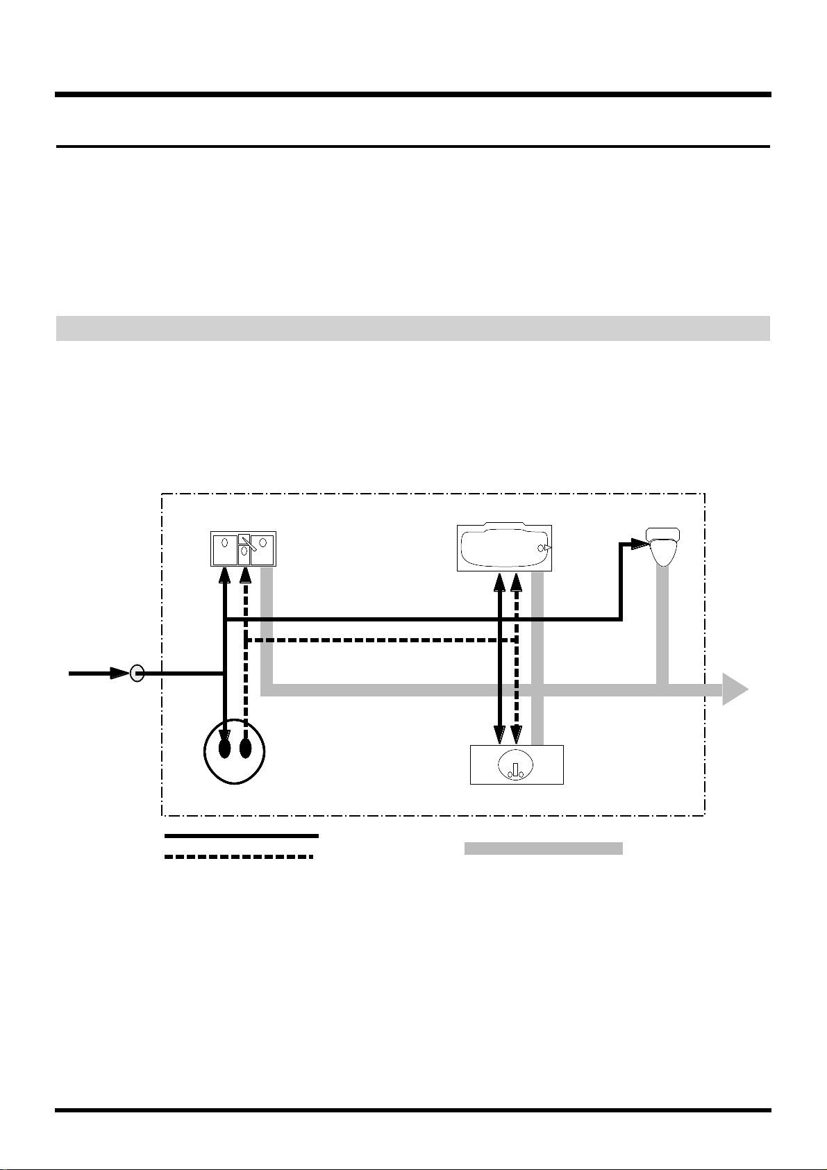
Mixer Section
The digital mixer specifies input or output status of the recorder section. The VS880EX contains an Input Mixer located before the recorder section, a Track
Mixer located after the recorder section, an Effect Return Mixer which controls
the effect return and Stereo In (p. 152), and a Master Block which determines
the output jacks from which the signal of each mixer will be output.
* For more detailed information about the mixer section, please refer to the “Mixer
Section Block Diagram” (Appendices p. 120).
Signal Flow (Buses)
On the VS-880EX, signals flow through buses. buses are shared lines through
which multiple signals can be routed efficiently to multiple tracks or channels. It may be easier to understand this if we use the analogy of water pipes.
For example, the water that is supplied by the water company to your house is
branched to a variety of locations within the house (kitchen, bathroom, toilet,
etc.). The water that is used at each of these locations is then collected into the
sewer, and carried away.
If we think of the VS-880EX as the house, the water being supplied from the
water company corresponds to inputs such as mic or guitar. Some of these
inputs are sent to recording tracks and are recorded. Other portions are sent to
the effects, and reverb or chorus are applied before they are output.
The basic principle of the VS-880EX is that by specifying in this way from where
and to where the common lines run, you can determine which input signals will
be recorded on which track or sent to which effects, and where they will be output.
Drain (Bus)
OUTPUT
to street
Water Heater
INPUT to house
from water line
Your House
Cold Water (Bus)
Hot Water (Bus)
Bath Sink
Bathtub
Kitchen Sink
INPUT
INPUTS INPUTS
INPUT
INPUTS
Toilet
OUTPUT
OUTPUT
OUTPUT
OUTPUT
OUTPUT
OUTPUT
Chapter 1 Before You Start (VS-880EX Terminology)
24
Page 25

The VS-880EX has the following buses.
RECORDING Bus:
Signals assigned to the RECORDING bus are routed to the recorder section to be
recorded. There are eight channels which can be assigned to the output of the
input mixer, track mixer, and effects (Return). Signals assigned to the RECORDING bus cannot be routed to the MIX bus.
MIX Bus:
Signals assigned to the MIX bus are sent to the MASTER jacks for monitoring. It
has two channels (L and R), and can take output signals from the input mixer,
track mixer, and effects (Return). Signals assigned to the MIX bus cannot be routed to the RECORDING bus.
EFFECT Bus:
Signals assigned to the EFFECT bus are sent to the effect to apply effects added
to them. It has two channels (FX1, FX2), and can process signals from the input
mixer and the track mixer. Signals assigned to the RECORDING bus as well as
the MIX bus can also be routed to the EFFECT bus.
AUX Bus:
Signals assigned to the AUX bus are routed to the AUX SEND jacks to allow
addition mixes for monitoring. This bus features two channels (AUX A, AUX B),
and can take signals from the input mixer and the track mixer. Signals assigned
to the RECORDING bus as well as the MIX bus can also be routed to the AUX
bus. This is convenient if, for example, you want to connect an external effects
device, or when you want an addition output separate from that of the MASTER
Out jacks (individual out).
Chapter 1 Before You Start (VS-880EX Terminology)
25
Chapter 1
Page 26
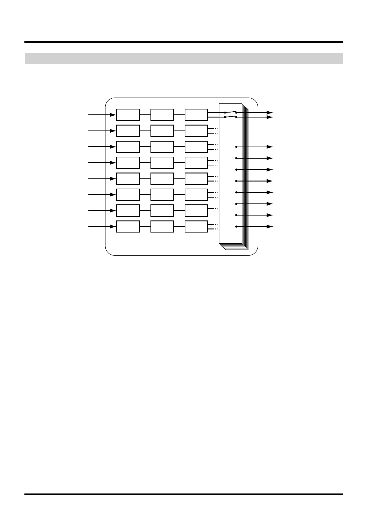
Input Mixer
Input mixer is placed before the recorder section, and correspond to the external
input sources (INPUT 1–6, DIGITAL IN L/R).
The output of each channel is assigned to tracks to be recorded. Channels not
assigned to tracks are output directly from the MASTER jacks. Additionally, the
status of tracks with signals assigned to them when not in record standby (STATUS indicator blinking red), also are output from the MASTER jacks. At this
time, the following signals are assigned to the channel faders.
Channels 1–6: INPUT jacks 1–6
Channels 7–8: DIGITAL IN connector L/R
EQ1 Fader1
EQ2 Fader2
EQ3 Fader3
EQ4 Fader4
EQ5 Fader5
EQ6 Fader6
EQ7 Fader7
EQ8 Fader8
INPUT 1
INPUT 2
INPUT 3
INPUT 4
INPUT 5
INPUT 6
DIGITAL IN L (7)
DIGITAL IN R (8)
Input Mixer (Channel 1–6, DIGITAL L/R)
Pan1
Pan2
Pan3
Pan4
Pan5
Pan6
Pan7
Pan8
REC 1 (Recorder)
REC 2 (Recorder)
REC 3 (Recorder)
REC 4 (Recorder)
REC 5 (Recorder)
REC 6 (Recorder)
REC 7 (Recorder)
REC 8 (Recorder)
MIX L/R (MASTER)
Chapter 1 Before You Start (VS-880EX Terminology)
26
Page 27

Track Mixer
Track mixer is placed after the recorder section, and correspond to the tracks
(1–8).
All of the tracks are output from the MASTER jacks. Additionally, tracks can
also be routed back to the RECORDING bus for overdubbing, or re-rerecording.
In this status, the channel faders 1–8 correspond respectively to Tracks 1–8.
Effect Return Mixer
This mixer adjusts the return level/balance from effects connected in
send/return fashion, and the level/balance of the stereo input.
Each channel is output from the MASTER jacks. It is also possible to assign them
to the recording bus for recording. In this case, the channel faders correspond to
the following signals.
Channel 6: The INPUT jack assigned to Stereo In
Channel 7: FX1 return
Channel 8: FX2 return
EQ1 Fader1
EQ2 Fader2
Pan1
Pan2
EQ3 Fader3
EQ4 Fader4
Pan3
Pan4
EQ5 Fader5
EQ6 Fader6
Pan5
Pan6
EQ7 Fader7
EQ8 Fader8
Pan7
Pan8
Track1
Track2
Track3
Track4
Track5
Track6
Track7
Track8
REC 1 (Recorder)
REC 2 (Recorder)
REC 3 (Recorder)
REC 4 (Recorder)
REC 5 (Recorder)
REC 6 (Recorder)
REC 7 (Recorder)
REC 8 (Recorder)
MIX L/R (MASTER)
Recorder Track Mixer (Track 1–8)
REC 1
REC 2
REC 3
REC 4
REC 5
REC 6
REC 7
REC 8
Fader6 Balance6
Fade7
Balance7
Fader8 Balance8
REC 1 (Recorder)
REC 2 (Recorder)
REC 3 (Recorder)
REC 4 (Recorder)
REC 5 (Recorder)
REC 6 (Recorder)
REC 7 (Recorder)
REC 8 (Recorder)
MIX L/R (MASTER)Stereo In
FX1 Return
FX2 Retuen
FX Return Mixer (Channel 6–8)
Chapter 1 Before You Start (VS-880EX Terminology)
27
Chapter 1
Page 28

Switching the Fader Functions
On the VS-880EX, it is able to adjust Input mixer or Track mixer by switching the
function of the channel faders on the top panel. Pressing [FADER] on the top
panel toggles between the input mixer and the track mixer. The FADER indicator indicates which mixer is currently selected.
Master Block
This selects the jacks or connectors connected to external equipment to which the
output of each mixer is sent.
Recorder Section
Differences with a Tape-Type MTR
Unlike DAT recorders, which use tape, digital disk recorders record performances (sounds) on a disk, as do MD recorders. Music that is recorded on
disk can be recalled and played back immediately, no matter where it is located
on the disk. This is also obvious from the difference in speed at which you can
move to the beginning of a song on a DAT recorder and on an MD recorder.
The ability to freely move to data regardless of the time or sequence at which it
was recorded is known as random access. In contrast, having to move to data
in the order of the time or sequence at which it was recorded is known as
sequential access.
lighting orange: Input Mixer
lighting green: Track Mixer
lighting red: Effect Return Mixer
MIX L/R MASTER L/R
AUX A, B
AUX A, B
FX1 L/R
FX2 L/R
REC bus
DIGITAL OUT 1
DIGITAL OUT 2
PHONES L/R
Masterblock
random access sequential access
Chapter 1 Before You Start (VS-880EX Terminology)
28
Page 29
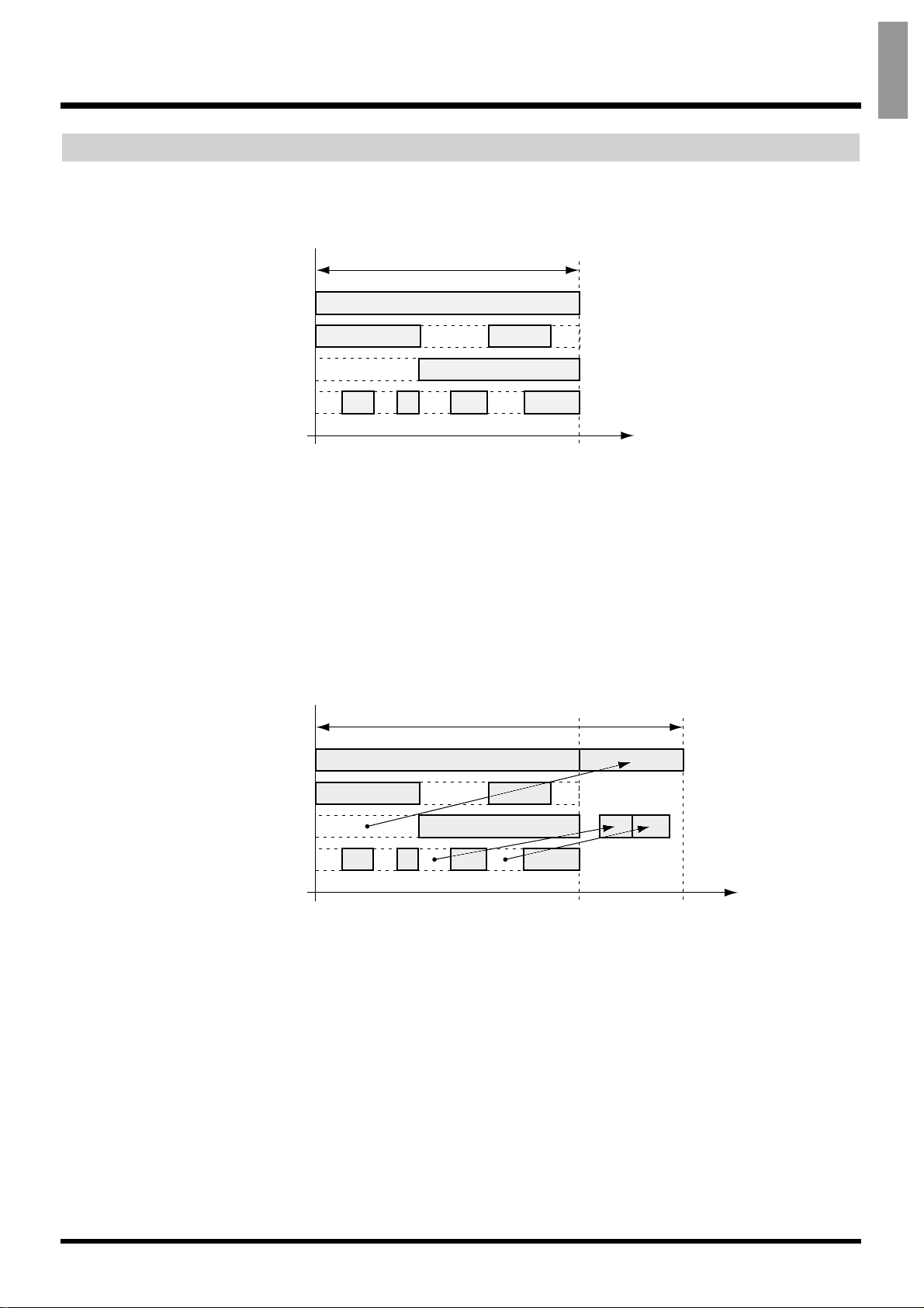
Track Minutes and Recording Time
With cassette tape recorders, the amount of time you can record on a tape is predetermined by the length of that tape. Moreover, any unused portion of the tape
is wasted.
In contrast, with disk recording, although available recording time is determined
by the amount of disk space, only the disk space used in recording is taken, and
beyond that, has no affect on the disk’s remaining free space. Thus, depending
on how you use tracks and phrases, the amount of available recording time will
vary. Thus, this calls for a standard unit corresponding to the time of one continuous monaural signal recorded to one track. This unit is referred to as a track
minute.
available recording time
Track 1
Track 2
Track 3
Track 4
00h00m00s00 00h30m00s00
Time
In Case of Tape Recording (using 30-minute tape)
available recording time
In Case of Disk Recording
Time
Track 1
Track 2
Track 3
Track 4
00h00m00s00 00h30m00s00 00h40m00s00
Chapter 1 Before You Start (VS-880EX Terminology)
29
Chapter 1
Page 30
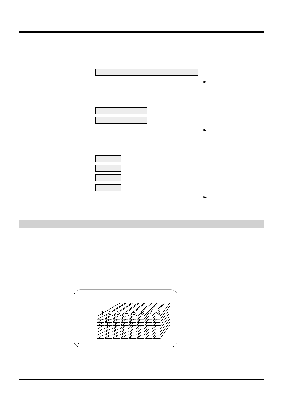
For example, 10 track minutes be used for 10 minutes of monaural recording, 5
minutes of stereo recording, 2 minutes and 30 seconds of recording on four
tracks, and so on.
Auxiliary Tracks for Each Track
The VS-880EX provides 8 playback tracks, and allows 8 tracks to be recorded
simultaneously. Each track is composed from the features 8 supplementary
tracks, each on of which can be used for recording or playback. These auxiliary
tracks are called V-tracks.
One song can contain two sets (banks) of 64 V-tracks (these 8 tracks x 8 V-tracks).
In other words, a maximum of 8 tracks x 8 V-tracks x 2 banks = 128 performance
tracks can be recorded. For actual recording/playback, you will specify the bank
that you wish to use, and then select one of the V-tracks.
* This Owner’s Manual provides a blank virtual track sheet to help you keep track of
your virtual track recordings (p. 129). Feel free to copy the sheet to use when you
record.
Track 1
Track 1
Track 2
Track 1
Track 2
Track 3
Track 4
00h00m00s00 00h10m00s00
00h00m00s00 00h05m00s00
00h00m00s00 00h02m30s00
Time
Time
Time
2
V-Track1
3
4
5
6
7
8
V-Track Bank A, B
Song
Chapter 1 Before You Start (VS-880EX Terminology)
30
Page 31

Effects Section
About the Effect Expansion Board
The VS-880EX contains effect. This allows you to use up to two stereo effects
(FX1 and FX2) simultaneously.
Connecting Effects
On the VS-880EX, there are two ways to connect the effects devices. Please read
and understand these differences described below.
Insert:
The effect is directly added either between each channel’s equalizer and fader or
before the master fader. Connect the effect in this manner if you want to use
effects applied to change the output of the sound itself, such as when using distortion or overdrive effects.
When inserting an effect into one of the channels or into the Master Block, that
effect cannot be used in another channel. For example, you insert FX1 into
Channel 1, then no other channel can access FX1.
Send/Return:
Besides the RECORDING bus and the MIX bus, the output of each channel can
also be sent to the EFFECT bus. Use this routing with effects such as reverb and
delay, when you want to mix the sound without effects and the sound after
effects have been applied.
EQ Fader Pan
FX 1
MIX bus or REC bus
EQ Fader Pan
FX 1FX Pan
MIX bus or REC bus
FX bus
Chapter 1 Before You Start (VS-880EX Terminology)
31
Chapter 1
Page 32

This chapter explains the basic operation of the VS880EX. This covers all of the fundamental processes,
including recording and editing, so please read and
understand this chapter.
Before You Begin
Turning On the Power
* To prevent malfunction and/or damage to speakers or
other devices, always turn down the volume, and turn off
the power on all devices before making any connections.
* Once the connections have been completed (Quick Start p.
3), turn on power to your various devices in the order
specified. By turning on devices in the wrong order, you
risk causing malfunction and/or damage to speakers and
other devices.
* Always make sure to have the volume level turned down
before switching on power. Even with the volume all the
way down, you may still hear some sound when the power
is switched on, but this is normal, and does not indicate a
malfunction.
1. Turn on the power with the POWER switch on
the rear panel of the VS-880EX.
When the VS-880EX starts up properly, the following
display will appear.
* When you turn on the power of the VS-880EX, the disk
drive must be recognized and certain required data must
be loaded. Thus, it takes a short while for the unit to start
up.
2. Turn on the power of connected audio equipment.
3. Raise the volume of the audio devices to appro-
priate levels.
4. If the display screen is difficult to read, hold
down [PLAY(DISPLAY)] and rotate the
TIME/VALUE dial.
If You Have Trouble Understanding
Displays or Operations
If you are unfamiliar with what is displayed on a
screen or find you are having difficulty understanding
a certain procedure, press [PLAY (DISPLAY)]. This
allows you to return immediately to the screen that
appears when the power is turned on. Try whatever
procedure you were working on from the beginning
once more.
• If an operation has been performed incorrectly or
cannot be executed correctly, an error message
appears in the display. When this occurs, please
refer to “Error Messages” (Appendices p. 9), and
perform the specified measure.
• If even after you perform an operation using the prescribed procedure the result differs from that stated
in Quick Start or in the Owner’s Manual, please refer
to “Troubleshooting” (Appendices p. 6).
• If the above steps do not resolve your problem, contact t a nearby Roland Service Center, or authorised
Roland distributor.
Before You Finish Operations
Saving the Performance to Disk
(Song Store)
Song data that you recorded or edited will be lost if
you simply turn the power off. Thus, you must execute the Shutdown procedure before turning the
power off.
When you switch songs or change disks, a message
will ask you to confirm whether the song should be
saved (STORE Current?) (p. 33).
Additionally, the contents of a recorded performance
can be lost because of unforeseen accidents, or even if
there is an accidental power failure or power outage.
Once lost, the contents of a recorded performance
cannot be restored to the previous conditions. To
avoid this from happening, use the following procedure to save your songs to the disk drive.
Current Song (Appendices p. 123)
* When handling important song data, or when using the
VS-880EX for extended periods, we strongly recommended you to execute the Song Store procedure frequently.
CONDITION MARKER#
MASTER
INPUT TRACK
AUX
TIME
48
24
4
0
dB
12
Chapter 2 Basic Operation
32
Page 33

1. Hold down [SHIFT] and press [STORE (ZERO)].
2. “STORE OK?” appears in the display. Press [YES].
If the song is saved properly, the initial display
reappears. If you wish to cancel the saving, press
[NO].
Turning Off the Power
The contents of any recorded performance will be lost
if you simply turn the power off. This may also result
in damage to the hard disk. To safely turn off the
power and be sure that your recorded performances
are saved, always be sure to follow the shutdown procedure when you finish working with the VS-880EX.
Shutdown (Appendices p. 124)
1. While holding down [SHIFT], press [SHUT/
EJECT (STOP)].
2. “SHUT/EJECT?” appears in the display. Press
[YES].
3. “STORE Current?” then appears in the display. If
you wish to save the current song, press [YES]. If
you do not wish to save it (if you want to undo
the contents of recording editing), press [NO]. If
you have selected a demo song, press [NO].
4. When shut down has been completed properly,
“PowerOFF/RESTART” appears in the display.
5. Turn down the volume of your audio equipment.
6. Turn off the power of the audio equipment.
7. Turn off the power of the VS-880EX with the
POWER switch on the rear panel.
* After the power is turned off, the momentum of the hard
disk causes it to continue spinning for a short while. Any
physical shock to the unit during this time may damage
the hard disk. Avoid moving the VS-880EX with a hard
disk installed for at least 30 seconds after turning off the
power.
If “STORE Current?” is Displayed
When you begin to execute the various operations
such as shutdown, the message “STORE Current?”
(Save the current song?) is displayed. This message
asks you whether you wish to save the currently
selected song to the disk drive. If you wish to save the
song before continuing with the shutdown, press
[YES]. If you want to proceed with the shutdown
without saving the song, press [NO].
If you press [YES] in response to the “STORE
Current?” message when Song Protect is on, or when
if you have selected a demo song, the message “Song
Protected” is displayed, and you will be unable to save
the song. Before editing a song, set Song Protect to
“Off” (p. 65). Otherwise, press [NO].
Restarting
You can restart the VS-880EX without turning off the
rear panel POWER switch. This is convenient when
switching disks in drives (such as the Zip drive) connected to the VS-880EX’s SCSI connector. Use the following procedure.
1. Perform the shutdown procedure as described in
“Turning Off the Power” (p. 33).
2. Confirm that “PowerOFF/RESTART” appears in
the display.
3. Hold down [SHIFT] and press [RESTART
(PLAY)].
This restarts the VS-880EX.
Chapter 2 Basic Operation
33
Chapter 2
Page 34

Basic Operations on the VS880EX
The VS-880EX features a wide variety of abilities
(functions) and settings (parameters). These are organized by type, function, operation, and so on. The
major organizational grouping within the song is
referred to as a condition. A list of the different conditions described below.
Play Condition:
Here you can perform normal playback/recording.
The VS-880EX is put in Play condition whenever the
power is turned on.
Channel Condition:
This is the condition in which input mixer, track
mixer, or effect return mixer-related settings are made.
Master Block Condition:
This is where you make settings for the mixer’s Master
Block.
Song Condition:
Executes the operations related to each of the songs.
Locator Condition:
This is where you make settings for the locator or
marker.
Track Condition:
Executes the operations related to each of the tracks.
Effect Condition:
In this status, you can make effects settings.
System Condition:
Here you can make settings that affect the entire environment of the VS-880EX.
Here is the general process used when executing the
functions and changing the settings included in each
condition. Please take a look.
1. Display the menu for each condition.
2. Select the page containing the desired function or
setting.
3. Select the setting to be changed.
4. Change the settings values.
5. Execute the operation.
Display Each of the Condition Menus
To select the desired condition, press either the EDIT
CONDITION button, CH EDIT button, or
[SHIFT]+{[EDIT(FADER)].
Selecting Pages Contained in Functions
and Settings
The menu for the corresponding page is displayed.
Use PARAMETER [ ] [ ] to select the desired
page, and press [YES]. It is also possible to switch the
menu display by repeatedly pressing the EDIT CONDITION button.
Master Block Condition
Edit Condition
Channel Condition
CONDITION MARKER#
MASTER
INPUT TRACK
AUX
TIME
48
24
4
0
dB
12
When System Condition is Selected
In some cases when System condition is selected,
the parameters themselves will be displayed
directly (rather than the System menu). This
allows you to immediately select the parameter
which was last modified. If you wish to view the
System menu, press [SYSTEM] once again.
Chapter 2 Basic Operation
34
Page 35

Select the Setting You Want to Change
Use PARAMETER [ ] [ ] to access the setting
(parameter) that you wish to modify. If two or more
settings are displayed simultaneously, use CURSOR
[ ] [ ] to move the cursor.
Change the Settings Values
Use the TIME/VALUE dial for this operation.
Rotating the dial counterclockwise decreases the values, rotating clockwise increases them. Although usually, increases and decreases in values are in single
unit steps, by holding down [SHIFT] while rotating
the TIME/VALUE dial, depending on the parameter,
you can make values increase or decrease ten times (or
one tenth) the normal rate.
Execute the Operation
After changing the value, to create the new song,
select the different song, or otherwise set or execute
the specified task or operation, press [YES]. A confirmation message will appear in the display. When the
message appears, press [YES]. If you want to cancel
the operation, then press [NO].
Switching Track Conditions
The condition for each track switches each time the
STATUS button is pressed. You can check the condition by looking at the button indicators.
SOURCE (orange):
Allows you to monitor the input source or track
assigned to each channel.
REC (blinking red):
Specifies what is recorded to each track. In playback,
tracks are monitored. You can directly specify what is
to be recorded by pressing the STATUS button while
holding down [REC].
REC (blinking red and orange):
Specifies what is recorded to each track. In playback,
sources are monitored. During playback, once again
press the STATUS button whose STATUS indicator is
blinking red.
PLAY (green):
Plays back each track. You can directly specify what is
to be played back by pressing the STATUS button
while holding down [STOP].
OFF (darkness):
The track is muted (silent).
* The VS-880EX can record up to eight tracks simultane-
ously.
CONDITION MARKER#
MASTER
INPUT TRACK
AUX
TIME
48
24
4
0
dB
12
Cursor location (display blinking)
decrease increase
Chapter 2 Basic Operation
35
Chapter 2
Page 36

Changing the Current Time
The current playback time in the display is shown in
SMPTE time code. The current measure, beat, and
Marker number are also displayed. Use the following
procedure to change the current playback time.
SMPTE Time Code (Appendices p. 124)
Moving in Frame Units
•To move in one-frame units, rotate the
TIME/VALUE dial.
• To move in ten-frame units, hold down [SHIFT] and
rotate the TIME/VALUE dial.
• To move in units of approximately 1/10 frame, first
press CURSOR [ ] until “¨” appears. The frame
numerical display will switch to sub-frame units
(approximately 1/100 frame). Then rotate the
TIME/VALUE dial. To return to the frame units,
press CURSOR [ ].
• To move in units of approximately 1/100 frame,
hold down [SHIFT] and rotate the TIME/VALUE
dial.
Moving in Measure/Beat Units
The MEASURE field in the display will indicate the
measure number of the current location, and the BEAT
field will indicate the beat number of the current location. For details on setting the measure and beat, and
how they correspond to the song, refer to “Sounding
the Metronome” (p. 154).
•
To move in measure units, use CURSOR [ ] [ ]
to move the cursor to the MEASURE field, and rotate
the TIME/VALUE dial.
•
To move in beat units, use CURSOR [ ] [ ] to
move the cursor to the BEAT field, and rotate the
TIME/VALUE dial.
* A “+” shown following the beat display indicates that this
time location is not at the beginning of the measure/beat.
When the time location is at the beginning of the measure/beat, the “+” indication will disappear.
Moving to the Beginning or End of the
Performance
You can move directly from within any of the V-tracks
in the currently selected track to the first or last location in the song that contains recorded sound. Use the
following procedure.
To go to the first location in the song containing
recorded sound:
Hold down [SHIFT] and press [SONG TOP (REW)].
To go to the last location in the song containing
recorded sound:
Hold down [SHIFT] and press [SONG END (FF)].
Storing a Time Location
With the VS-880EX, there are two ways you can mark
and easily recall sections of a song that you want to
record over or listen to repeatedly. One is called the
Locator function, and the other one is referred to as
the Marker function. Use each method according to its
intended function.
Locator:
Store “locator,” or time locations to the LOCATOR
([1/5]–[4/8]) buttons on the top panel of the VS880EX. In conjunction with [SHIFT], you can register
up to eight time locations, and move immediately to a
registered location simply by pressing a button. There
are four banks for each button, providing you with up
to 32 (8 x 4) locators.
Marker:
Up to 1000 locate points (000–999) can be set in rapid
succession in each song. You can also store Auto Mix
data (p. 143), and there is a sync track provided as well
(p. 123).
1
2
3
4
5
6
7
8
Song Top Song End
Chapter 2 Basic Operation
36
Page 37

Using the Locator
Time locations are stored with the LOC buttons
([1/5]–[4/8]) on the top panel of the VS-880EX. In conjunction with [SHIFT], you can register up to eight
time locations, and move immediately to a registered
location simply by pressing a button. There are four
banks for each button, providing you with up to 32 (8
x 4) locators. The locators are also a useful and convenient way to define sections of a song to be repeated in
Loop Recording or for marking points in Punch-In
Recording.
Storing Locators
1. Move to the location in a song where you want to
set a locator.
2. Press a LOC button ([1/5]–[4/8]). For example, if
you wish to set Locator 1, press [1/5]. If you wish
to store the location in Locator 5, hold down
[SHIFT] and press [1/5].
These can be used in recording/playback or while the
song is stopped. When a locate point is set, the corresponding indicator lights.
Moving to a Stored Time Location
1. Press the LOCATOR button for the locate point to
which you want to move. For example, if you
wish to move to the Locator 1, then press [1/5]. If
you wish to move to the location registered in
Locator 5, hold down [SHIFT] and press [1/5].
Changing the Locator Bank
1. Press [LOCATOR].
The current locator bank number will be displayed as
“Locate Bank = 1” etc. Simultaneously, the LOC indicator corresponding to the current bank number will
blink.
2. Continue holding [LOCATOR], and press the
LOC button ([1/5]–[4/8]) for the bank number
that you wish to change.
[LOCATOR] is used both to recall the Locator condition and to switch the Locator Bank. If you take your
finger off [LOCATOR] without changing the Locator
Bank, the display screen may change.
3. Release your finger from [LOCATOR].
4. As described in the procedure for “Storing a Time
Location,” register the locator point.
Making Fine Adjustments to Stored
Locators
1. Move to the locator whose time you wish to
change. Use the LOC buttons ([1/5]–[4/8]).
2. Press [LOCATOR] several times until “LOC Loc*”
(* is the locator number that you wish to change)
is displayed.
3. Use the TIME/VALUE dial to input the desired
time.
4. When you finish making adjustments, press
[PLAY(DISPLAY)].
Return to Play condition.
87654321
87654321
87654321
00h00m00s00 Time
Bank 2
Bank 1
Bank 4
87654321
Bank 3
Chapter 2 Basic Operation
37
Chapter 2
Page 38

Deleting a Stored Time Location
1. While holding down [CLEAR], press the LOC
button ([1/5]–[4/8]) for locate point that you wish
to delete. For example, if you wish to delete the
LOCATOR 1’s located point, then press [CLEAR]
and [1/5] simultaneously. If you wish to delete
the time that was registered in Locator 5, hold
down [SHIFT] and press [CLEAR] and [1/5].
Using Markers
Along with the playback locate points, you can set up
to 1000 Markers in sequence. The Markers are also a
useful and convenient way to define sections of a song
to be repeated in Loop Recording or for marking
points in Punch-In Recording.
* An interval of at least 0.1 seconds must left between
markers. It will not be possible to add a new markers if a
markers already exists at a location less than 0.1 seconds
away.
Marking a Time Location
Press [TAP], and a marker will be added to the current
location. This can be done during recording or playback of the song as well as when the song is stopped.
Moving the Location of Markers
To move to the Marker immediately preceding the
current playback time, press [PREVIOUS]. You move
ahead one marker at a time in the order they are
placed each time the button is pressed. To move to the
Marker immediately following the current playback
time, press [NEXT].
0123 456
TAP TAP TAP TAP TAP TAP TAP
00h00m00s00 Time
012
Time
PREVIOUS
NEXT
Displaying Markers
The Marker number at any playback location is
indicated in the display. If there is no Marker
number in the current location, then the closest
preceding Marker number is displayed. If there
are no markers in the song, “—” is indicated. If
“***” is shown in the display, it indicates that
although there are markers placed in the song, the
current location is before the first marker.
Chapter 2 Basic Operation
38
About Marker Numbers
Each marker is assigned a number 000-999, in the
order of its time location. This means that if you
add a new marker at a location earlier than an
existing marker, the numbers of the subsequent
markers will be incremented.
01 23
TAP
Time
Before setting a Marker
01 342
Time
After setting a Marker
Page 39

Moving the Location of Markers
1. Press [PLAY (DISPLAY)].
2. In the display, the “MARKER” field will indicate
the marker number of the current location. Use
CURSOR [ ] [ ] to move the cursor to the
MARKER field, and rotate the TIME/VALUE
dial.
Making Fine Adjustments to Marked
Locations
1. Move to the marker where you want to change.
Press [PREVIOUS] or [NEXT] to move the marker.
2. Press [LOCATOR] several times until “LOC ***”
appears in the display (*** is the marker number
that you wish to modify).
3. Set the marker where you wish to change. Use the
TIME/VALUE dial. The time of a marker can be
modified only within the range between the preceding and following markers.
4. Press [PLAY (DISPLAY)].
Return to Play condition.
Deleting a Marked Location
Setting markers makes it much easier to search for
places within a song, but having too many of them
actually cam make it more difficult to find the location
you’re looking for. It is a good idea to delete unneeded
markers whenever you can.
1. Move to the marker you wish to delete. Press
[PREVIOUS] or [NEXT] to move the marker.
2. While holding down [CLEAR], press [TAP].
Delete the marker. Marker numbers for any markers
after the deleted mark point shift one number ahead.
To Delete All Markers Simultaneously
1. Hold down [SHIFT] and [CLEAR] and [TAP] at
the same time.
2. “Clear ALLMarker ?” appears in the display. If
you want to delete the markers, press [YES]. If
you want to cancel the procedure, the press [NO].
0111 2
Time
Possible range of change
01 342
Time
Before deleting a Marker
TAPCLEAR
+
01 23
Time
After deleting a Marker
01 342
Time
Before deleting a Marker
TAP
CLEAR
++
SHIFT
Time
After deleting a Marker
Chapter 2 Basic Operation
39
Chapter 2
Page 40

This chapter explains the operations necessary for
recording with the VS-880EX. Try out each operation
as you read these instructions.
Recording
Items Necessary for Multi-Track
Recording
• VS-880EX (1)
• Internal IDE hard disk
• Audio equipment for the Master Out signal, or
stereo headphones
• Recording source (electric guitar, synthesizer, CD
player, etc.) or microphone
Creating a New Song (Song New)
Recording cannot take place while a demo song is
selected. This is because the contents of the demo
songs are protected from being changed or overwritten (p. 64). Use the following procedure to prepare
a new song. This process is analogous to exchanging
cassettes on a multi-track tape recorder.
1. Press [SONG] several times until “SNG Song New
?” appears in the display.
2. Press [YES].
3. “SNG SampleRate=” appears in the display. Use
the TIME/VALUE dial to select a sample rate.
Sample Rate
Select a sample rate (32 kHz, 44.1 kHz, or 48.0 kHz).
When you want to use a digital connection to a digital
audio device, much the sample rate to that of the connected device. Furthermore, when making an origi-
nal audio CD, select 44.1 kHz. You cannot change
the sample rate after the song is recorded. In addition,
you cannot mix different sample rates in the same
song.
4. Press PARAMETER [ ].
5. “Record Mode=” appears in the display. Use the
TIME/VALUE dial to select a recording mode.
Record Mode (Recording Mode)
Select the sound’s quality and time based on the
recorded contents. Once a song is recorded, these settings cannot be changed.
MAS (Mastering):
With this setting, you can get the high-quality sounds
compatible to that’s quality of CD player or DAT
recorder. However a song for which this mode is
selected will function as a 6-track recorder (1–6). This
mode is appropriate when recording edited two-channel stereo songs.
MT1 (Multi-Track 1):
While maintaining high-quality sound, recording time
is approximately twice that available in “Mastering”
mode. This mode is good when doing a lot of track
bouncing.
MT2 (Multi-Track 2):
While maintaining high-quality sound, recording time
is longer than that available in “Multi-Track 1” mode.
This mode is good for normal operations.
LIV (Live):
Recording time is longer than with “Multi-Track 2”
mode. This mode is appropriate when your hard disk
lacks much free space or when recording live performances.
6. Press [YES].
“Create New - Sure?” appears in the display.
7. Press [YES].
“STORE Current?” appears in the display.
8. If you wish to save the current song, press [YES];
if not, press [NO]. If you have selected a demo
song, then press [NO].
9. When a new song has been created, you will return
to Play condition. The newly created song will be
selected as the song for recording/playback.
Chapter 3 Multi-Track Recording
40
About Recording Time
The recording time (track minutes) of both sampling rate and recording mode are as shown
below (for one track, with 2 GB free space).
Track Minutes (Appendices p. 125)
Recording Sample Rate
Mode 48.0 kHz 44.1 kHz 32.0 kHz
MAS 185+185 mins. 202+202 mins. 278+278 mins.
MT1 371+371 mins. 404+404 mins. 557+557 mins.
MT2 495+495 mins. 539+539 mins. 742+742 mins.
LIV 594+594 mins. 646+646 mins. 891+891 mins.
(All times approximate)
* The above chart is a general yardstick for estimating
recording times. Actual times may be somewhat
shorter depending on your hard disk’s specifications
or the number of songs created.
Page 41

General Course of the
Recording Process
The procedure for recording with the VS-880EX is
roughly as same as record process by multi-track
recorders as mentioned before. This general process of
recording a song is outlined below. Please take a
moment to read through the steps.
1. Connect instruments and microphones to the VS-
880EX.
2. Record the basic part of the song; drums and bass,
etc.
3. Record other parts (electric guitars, synthesizers,
vocals, etc.) while playing back the basic part.
4. If there are any mistakes during the process,
record over the places where they occurred
(punch-in/punch-out).
5. Adjust the volume level, pan, equalization, and
other settings for each part.
6. If you run out of empty tracks, you can marge the
contents of two or more tracks onto a different
track (track bouncing).
7. Mix down the tracks to your recorder and make a
master tape.
Well, it’s time to try multi-track recording. This will be
explained using concrete examples.
Connecting Instruments
1. Turn down the master fader as low as possible.
2. Connect instruments and microphones to the
INPUT jacks.
* Howling could be produced depending on the location of
microphones relative to speakers. This can be remedied by:
1.
Changing the orientation of the microphone(s).
2. Relocating microphone(s) at a greater distance
from speakers.
3. Lowering volume levels.
If “Drive Busy!” is Displayed
If this message appears during recording or playback, it means that the disk drive cannot catch up
with the data read/write speed. In such instances,
create a new song which lower the sample rate or
recording mode from their current settings, and
record over.
Chapter 3 Multi-Track Recording
41
Chapter 3
Song Numbers
On the VS-880EX, management of song data is
accomplished by assigning a song number to
every song that is saved. Newly created songs are
given the lowest currently available number. For
example, if all numbers up to song number 5 are
already assigned, then the number 6 is taken by
the new song. Furthermore, even if song numbers
up to 5 are occupied, if Song 3 is deleted, then the
new song is given that now lowest vacant number.
InitSong 001
InitSong 002
InitSong 003
InitSong 004
InitSong 005
Disk Drive
InitSong 001
InitSong 002
InitSong 003
InitSong 004
InitSong 005
InitSong 006
Disk Drive
Song New
InitSong 001
InitSong 002
InitSong 004
InitSong 005
Disk Drive
InitSong 001
InitSong 002
InitSong 003
InitSong 004
InitSong 005
Disk Drive
Song New
If song numbers up to 5 are occupied
If Song 3 is deleted
Page 42

Recording to the Tracks
1. Select a recording track. While holding down
[REC], press the STATUS button for the track to
which you want to record.
The STATUS indicator blinks red.
2. Switch to the input mixer. Press [FADER (EDIT)]
several times to let the FADER indicator light
orange.
3. Select source to be recorded to the track. While
holding down the STATUS button for the track to
which you want to record, press the SELECT button for the input channel whose source you want
assigned to the track.
The SELECT indicator blinks.
4. Determine the source volume. Since what is
recorded is the sound after it passes through the
fader, the faders should normally be set to around
0 dB.
5. Adjust the input sensitivity, with the INPUT knob
of the channel input assigned as the source. Get a
strong input signal by having instrument volumes
as high as possible. At this time, raise the volume
level as much as possible without making the
PEAK indicator light up. Normally, this range is
adjusted that the level meter moves within -12
to 0 dB when the channel fader is set to 0 dB.
6. Press [REC].
The REC indicator blinks red.
7. Press [PLAY].
The PLAY indicator lights green, and recording starts.
Now begin playing.
8. When the performance is finished, press [STOP].
The song then stops.
9. Listen to the recorded performance. Press [ZERO]
to return to the beginning of the song.
10. Switch to the track mixer. Press [FADER] several
times to let the FADER indicator light green.
11. Press [PLAY] to begin playback of the song.
12. Use the channel faders and the master fader to
adjust the volume to a comfortable level.
13. Does the recording sound as you though it
would? If you are satisfied with the results of
your recording, then save the song to the disk,
using the procedure described in “Saving a
Recorded Performance” (p. 43).
To cancel track assignments
You can cancel all assignments (routings) of
sources or tracks to tracks (i.e., to a state where
nothing is connected).
1. Press [PLAY (DISPLAY)].
2. Hold down the STATUS button and press
[CLEAR].
Chapter 3 Multi-Track Recording
42
Sources Assigned to Tracks
In a newly created song, sources are assigned to
tracks as shown below.
Viewing the Assign screen
In Play Condition, hold down the STATUS button
to view the source/track/effect which is assigned
to that track.
CONDITION MARKER#
MASTER
INPUT TRACK
AUX
TIME
48
24
4
0
dB
12
Recording Tracks (1–8)
Assigned source 1–8 (upper line)
Assigned track 1–8 (lower line)
Stereo In (first line)
Effect 1 (second line)
Effect 2 (third line)
Page 43

Saving a Recorded
Performance (Song Store)
The contents of any recorded performance will be lost
if you simply turn the power off, or even if there is an
accidental power failure or power outage. Once lost,
the contents of a recorded performance cannot be
restored to the previous conditions. To avoid this
from happening, use the following procedure to save
your songs to the disk.
* When handling important song data, or when using the
VS-880EX for extended periods, we recommended that
you to perform this procedure frequently.
1. Hold down [SHIFT] and press [STORE (ZERO)].
2. “STORE OK?” appears in the display. If you are
satisfied with the results of your recording, press
[YES]. If you wish to cancel the save, press [NO].
* The contents of the demo songs are protected from being
changed or overwritten (Song Protect (p. 64)). You cannot save operation with the demo songs. This means if you
press [YES] at Step 2 when a demo song is selected, the
message “Song Protected” will appear, and the procedure
cannot be continued.
Chapter 3 Multi-Track Recording
43
Chapter 3
When You Are Recording in Stereo
When recording in stereo, or when recording to
tracks with Channel Link (p. 149) on, you can set
the pan for each input channel. After Step 5, perform the procedure described below.
5-1. Press the SELECT button for the input chan-
nel you want assigned as the source.
The SELECT indicator lights.
5-2. Press PARAMETER [ ] [ ] several
times until “MIX Sw” appears in the display.
5-3. Rotate the TIME/VALUE dial.
MIX Sw (Mix Switch)
This selects the bus to which the source or track
output will be assigned. For this example select
“On.”
On: The source or track will be sent to the mix
bus. Set this to “On” when, for example,
you simply want to mix the inputs without
recording the source. However, the sources
that are assigned to the RECORDING bus
are disabled.
Off: The source or track will not be assigned to
the mix bus. If it is not assigned to a recording bus either, then that source/track will
not be output anywhere.
5-4. Press PARAMETER [ ].
5-5. Rotate the TIME/VALUE dial.
MIX Pan
This adjusts the pan setting (L63–0–R63) of the
signal sent to the MIX bus and the RECORDING
bus.
5-6. Repeat Steps 5-1 through 5-3 for all input
channels to which you want to make pan
settings.
5-7. After making the pan setting, press [PLAY
(DISPLAY)].
Return to Play condition.
Page 44

Recording Over a Portion of
a Performance
(Punch-In/Punch-Out)
Sometimes, when listening to a recorded performance,
even if you don’t find it necessary to discard the entire
song, there may be sections containing mistakes or
lyrics that are hard to hear. In such instances, you will
find the following procedure convenient for rerecording only selected parts of a recording. The switching
from playback to recording status is called punch-in,
and the switch back from recording to playback is
referred to as punch-out.
Using the RECORD Button
(Manual Punch-In 1)
Use Transport Control Buttons to punch in and out.
1. Hold down [REC] and press the STATUS button
which you wish to re-record.
2. Press [ZERO] to return to the beginning of the
song.
3. Press [PLAY] to begin playback of the song.
At this point, the performance that has already been
recorded on the track or tracks that you want to rerecord is monitored.
4. Press the STATUS buttons again.
The STATUS indicator alternately blinks red and
orange. Now, confirm that you can hear source you
want recorded to the track coming from the monitors.
5. During playback of the song, each time the button
is pressed, the monitor switches between source
and track. Using the input sensitivity knob, adjust
the volume of the source so that it matches that of
the prerecorded performance.
6. Once you have adjusted the input sensitivity,
press [STOP].
7. Move to previous located point where you want
to re-record.
8. Press [PLAY] again to playback the song.
9. When you reach the point in the performance you
want to re-record, press [REC].
The VS-880EX goes in to record mode; start rerecording the song or performance.
10. When you have finished recording, press [REC]
once more (or press [PLAY] to playback the song).
11. Each time the [REC] button is pressed, the unit
alternately punches in and out. Repeat Steps 9
and 10 for any other tracks you wish to re-record.
12. Press [STOP] to stop the song.
13. Listen to the results of the rerecording. Return to
the beginning of the song and press [PLAY].
Using the Foot switch
(Manual Punch-In 2)
Use a foot switch to punch in and out. Using PunchIn/Punch-Out when both performing on an instrument and recording at the same time is difficult. In
such instances, it is convenient to use a foot switch
(such as the DP-2 or the BOSS FS-5U) to do your
switches.
Time
Recording
Playback
Playback
Start Punch-in Punch-out Stop
Time
Recording
Playback
Playback
Start Punch-in Punch-out Stop
Chapter 3 Multi-Track Recording
44
Page 45

1. Connect an optional foot switch (such as the DP-2
or the BOSS FS-5U) to the VS-880EX’s FOOT
SWITCH jack.
2. Press [SYSTEM] several times until “SYS System
PRM?” appears in the display.
3. Press PARAMETER [ ] several times until
“SYS FootSw=” appears in the display.
FootSw (Foot switch icon)
Set the function of the foot switch connected to the
FOOT SWITCH jack.
Play/Stop: Repeats playback and recording each
time the foot switch is pressed.
Record: Performs the same function as [REC].
This is used for switching between
recording and playback during manual
Punch-In Recording.
TapMarker: Performs the same function as [TAP].
Pressing the foot switch sets a Marker at
the mark point.
Next: Performs the same function as [NEXT].
Moves to the beginning or end of the following phrase each time the foot switch is
pressed.
Previous: Performs the same function as [PREVI-
OUS]. Moves to the beginning or end of
the previous phrase each time the foot
switch is pressed.
GPI: Controls playback and recording of the
song depending on the GPI trigger signal
received from the FOOT SWITCH jack.
GPI(Appendices p. 123)
4. Select “Record” with the TIME/VALUE dial.
5. Press [PLAY (DISPLAY)].
Return to Play condition.
Now, you can switch the setting of the FOOT SWITCH
jack between Punch-In and Punch-Out by the foot
switch. Carry out Manual Punch-In as described in
“Using the RECORD Button (Manual Punch-In 1” (p.
44). However, use the foot switch instead of the [REC]
button to perform the operation.
Specifying Beforehand the Location
for Rerecording (Auto Punch-In)
You can automatically punch in and punch out at previously specified locations. This function is called
Auto Punch-In. This is convenient when you need to
punch in or out at a precise time. Before you begin
recording, set the times for punch-in/punch-out.
There are three ways to set these times as described
below. Use the method appropriate for your situation.
Using Locators
1. Preset locate points where you want to punch
in/punch out.
2. While holding down [AUTO PUNCH], press the
LOC button ([1/5]–[4/8]) specifying the locate
point for the time at which you want to punch in.
3. Then, without releasing [AUTO PUNCH], press
the LOC button ([1/5]–[4/8]) specifying the locate
point for the punch-out time.
Chapter 3 Multi-Track Recording
45
Chapter 3
Page 46

Using Markers
The space between two adjacent mark points can be
used to define the segment for Punch-In Recording.
1. Preset Markers where you want to punch in and
then punch out.
2. Move to the mark point located at the desired
punch-in time.
3. While holding down [AUTO PUNCH], press
[NEXT].
4. Without releasing [AUTO PUNCH], press [PRE-
VIOUS].
Specifying the Points While the Song
Plays Back
1. Press [PLAY] to begin playback of the song.
2. When you reach the desired punch-in location,
hold down [AUTO PUNCH] and press [TAP].
3. Continue holding down [AUTO PUNCH], wait
for the desired punch-out location, and then press
[TAP] once again.
4. Press [STOP].
Making Fine Adjustments to the
Punch-In Segment
1. Press [LOCATOR] several times until “LOC
APin” appears in the display.
2. The punch-in time will be displayed. (If no punchin time has been specified, the display will indicate “–h–m–s–f–.”) Use the TIME/VALUE dial to
adjust the time.
3. Press PARAMETER [ ].
“LOC APOt” appears in the display.
4. The punch-out time will be displayed. (If no
punch-out time has been specified, the display
will indicate “–h–m–s–f–.”) Use the
TIME/VALUE dial to adjust the time.
5. Press [PLAY (DISPLAY)].
Return to Play condition.
Recording Procedure:
1. Hold down [REC] and press the STATUS button
for the track you wish to re-record.
2. Press [ZERO] to return to the beginning of the
song.
3. Press [PLAY] to begin playback of the song.
At this point, the performance that has already been
recorded on the track or tracks that you want to rerecord is monitored.
4. Press the STATUS buttons again.
The STATUS indicator alternately blinks red and
orange. Now, confirm that you can hear source you
want recorded to the track coming from the monitors.
5. During playback of the song, each time the button
is pressed, the monitor switches between source
and track. Using the input sensitivity knob, adjust
the volume of the source so that it matches that of
the prerecorded performance.
6. Once you have adjusted the input sensitivity,
press [STOP].
CONDITION MARKER#
MASTER
INPUT TRACK
AUX
TIME
48
24
4
0
dB
12
Chapter 3 Multi-Track Recording
46
Page 47

7. Press [AUTO PUNCH].
The AUTO PUNCH indicator lights, and Auto PunchIn Recording is enabled.
8. Move to a previous locate point where you want
to re-record.
9. Press [REC].
10. Press [PLAY] again.
Playback of the song begins.
11. The VS-880EX automatically goes into record
mode at the point where the punch-in is set. Start
the song or performance now.
12. When you reach the point where the punch-out is
set, the VS-880EX automatically returns to playback mode. Press [STOP] to stop the song.
13. Listen to the results of the rerecording. Return to
the beginning of the song and press [PLAY].
Repeatedly Recording Over the Same
Area (Loop Recording)
You can repeatedly play back a specified area (the
loop) and use Auto Punch-In Recording in that area.
This is called Loop Recording. This is convenient for
when you want to check the results immediately after
recording, or if you want to record a number of takes
of a guitar solo and compare the different takes.
Before you begin recording, specify the begin and end
times for the loop. There are three ways to specify the
loop times. Use the method appropriate for your situation.
* To specify the area re-recording (the punch-in point and
punch-out point), refer to the previous section “Auto
Punch-In.”
* Make settings so that the loop completely includes the
area to be rerecorded (i.e., from the punch-in point to the
punch-out point). If the area to be rerecorded is not completely within the loop, recording may not start at the
specified location, or may be interrupted in the middle of
the area for recording.
Using Locators
1. First store locate points where you want to begin
and end the loop.
2. While holding down [LOOP], press the LOCA -
TOR button for the locate point where you want
the loop to begin.
3. Without releasing [LOOP], press the LOCATOR
button which specified the end of the loop.
To Use Markers
Adjacent mark points can be used to set the beginning
and end of the loop.
1. First, set mark points where you want to punch in
and punch out.
2. Move to the mark point at the beginning of the
loop.
3. While holding down [LOOP], press [NEXT].
4. Without releasing [LOOP], press [PREVIOUS].
Time
Recording
Playback
Playback
Loop start Punch-in Punch-out Loop end
Chapter 3 Multi-Track Recording
47
Chapter 3
Page 48

Specifying The Points While the Song
Plays Back
1. Press [PLAY] to begin playback of the song.
2. When you reach the desired location for the
beginning of the loop, hold down [LOOP] and
press [TAP].
3. Continue holding down [LOOP], and when you
reach the desired location for the end of the loop,
press [TAP] once again.
4. Press [STOP].
Making Fine Adjustments to the Loop
1. Press [LOCATOR] several times until “LOC LpSt”
appears in the display.
2. The loop start time will be displayed. (If no loop
start time has been specified, the display will indicate “–h–m–s–f–.”) Use the TIME/VALUE dial to
adjust the time.
3. Press PARAMETER [ ].
“LOC LpEd” appears in the display.
4. The loop end time will be displayed. (If no loop
end time has been specified, the display will indicate “–h–m–s–f–.”) Use the TIME/VALUE dial to
adjust the time.
5. Press [PLAY (DISPLAY)].
Return to Play condition.
Recording Procedure
1. Hold down [REC] and press the STATUS button
for the track you wish to re-record.
2. Press [ZERO] to return to the beginning of the
song.
3. Press [PLAY] to begin playback of the song.
At this point, the performance that has already been
recorded on the track or tracks that you want to rerecord is monitored.
4. Press the STATUS buttons again.
The STATUS indicator alternately blinks red and
orange. Now, confirm that you can hear source you
want recorded to the track coming from the monitors.
5. During playback of the song, each time the button
is pressed, the monitor switches between source
and track. Using the input sensitivity knob, adjust
the volume of the source so that it matches that of
the prerecorded performance.
6. Once you have adjusted the input sensitivity,
press [STOP].
7. Press [LOOP].
The LOOP indicator lights, and Auto Punch-In
Recording is enabled.
8. Press [AUTO PUNCH].
The AUTO PUNCH indicator lights. You are now set
to do Loop Recording.
9. Press [PLAY].
Playback of the song begins. The song is played back
until the end of the loop is reached, playback will
return to the loop start point, and repeat.
10. Press [REC] where you want to re-record. The VS880EX will then automatically go into record
mode at the point where the punch-in is set. Start
the song or performance then.
11. When you reach the point where the punch-in is
set, the VS-880EX automatically returns to playback mode. Playback continues until the end of
the loop, and the loop repeats from the start point
once again.
12. With the next playback of the loop, listen to what
you recorded to check the result. If the recording
hasn’t turned out as you intended, repeat Steps 10
and 11.
13. Press [STOP] to stop the song.
14. Listen to the results of the recording once more.
Press [LOOP].
The LOOP indicator goes off.
15. Press [AUTO PUNCH].
The AUTO PUNCH indicator goes off.
16. Return to the beginning of the song and press
[PLAY].
CONDITION MARKER#
MASTER
INPUT TRACK
AUX
TIME
48
24
4
0
dB
12
Chapter 3 Multi-Track Recording
48
Page 49

Recording to Other Tracks
(Overdubbing)
In multi-track recording, the normal process is to
record new tracks while listening to the performance
on previously recorded tracks played back. This is
referred to as overdubbing.
1. Select the tracks you want to play back. While
holding down [STOP], press the STATUS buttons
for the tracks you want to play back (i.e., that you
want to hear while overdubbing).
The STATUS indicators light green.
2. Select the tracks to which you want to record.
While holding down [REC], press the STATUS
buttons for the tracks to which you want to
record.
The STATUS indicators blink red.
3. Select the sources to record to the tracks. While
holding down the STATUS buttons for the tracks
you want to record to, press the SELECT buttons
for the input channels whose sources you want
assigned to the tracks.
The SELECT indicators blink.
4. Now you are ready for overdubbing. Follow the
Steps of “Recording to the Tracks” (p. 42), to
record and then check the content.
Recording on V-Track 2
The VS-880EX features 8 tracks, each of which contains
8 auxiliary tracks. These subsidiary tracks are referred
to as V-tracks.
Each song can have two sets (A and B) of these 64 Vtracks (8 tracks x 8 V-tracks), and each such set is
referred to as a V-track bank.
By using all of these tracks to their full potential, you
can create recordings of up to 128 (64 (V-track) x 2 (Vtrack bank)) tracks.
Switching V-Tracks
1. Press [CH EDIT (SELECT)] for the track whose V-
track you wish to switch.
2. Hold down [SHIFT] and press the channel 2
[V.Track (CH EDIT)].
3. “V.Track=” appears in the display. Using the
TIME/VALUE dial to select the V-track.
4. Press [PLAY (DISPLAY)].
Return to Play condition.
5. As described in “Recording to the Tracks” (p. 42),
record and check the contents.
Switching V-Track Bank
1. Press [SYSTEM] several times until “SYS System
PRM ?” appears in the display.
2. Press [YES] .
3. Press PARAMETER [ ] several times until
“V-Track Bank =” appears in the display.
4. Rotate the TIME/VALUE dial. Select “A” or “B.”
5. Press [PLAY (DISPLAY)].
Return to Play condition.
6. As described in “Recording to the Tracks” (p. 42),
record and check the contents.
CONDITION MARKER#
MASTER
INPUT TRACK
AUX
TIME
48
24
4
0
dB
12
Tracks on which sound is recorded
V-Track Bank
V-Track
Chapter 3 Multi-Track Recording
49
Chapter 3
Page 50

Using Effects
Applying Effects to the Playback
When you playback a song, you will frequently want
to apply effects such as reverb or delay. Here we will
explain how to apply reverb as you playback previously recorded tracks.
Select an Effect
1. Press [EFFECT] several times until “EFFECT-1
PRM?” appears in the display.
2. Press [YES].
The number and name of the currently selected effect
will be displayed, and you can select the desired
effect.
3. Use the TIME/VALUE dial to select the effect you
wish to use. Here, select “A00 RV:LargeHall.”
4. After selecting the effect, press [YES].
Specify the Tracks for Playback
5. Press [FADER (EDIT)] several times to let the
FADER indicator light green.
6. Hold down [STOP] and press the STATUS button
for the track you want played back.
The STATUS indicator lights green.
7. Press [CH EDIT (SELECT)] for the track to which
you want to apply reverb.
The CH EDIT indicator lights.
8. Hold down [SHIFT] and press the channel 7
[EFFECT-1 (CH EDIT)].
“EFFECT1=” appears in the display.
9. Rotate the TIME/VALUE dial.
EFFECT1 (Effect 1 Send Select Switch)
This sets how the signal is sent to the EFFECT 1 bus.
Here, select “PstFade” (post-fader) to apply reverb to
the sound after the output of the channel fader.
Off: The signal is not sent.
PreFade: The signal before passing through the
channel fader is sent.
PstFade: The signal after passing through the
channel fader is sent.
If the effect has been inserted into another channel, the
effect cannot be used. But, the signal from the channel
will be sent to EFFECT bus.
10. Press PARAMETER [ ].
“EFFECT1 Send=” appears in the display.
11. Rotate the TIME/VALUE dial.
EFFECT1 Send (Effect 1 Send Level)
This adjusts the level (0–127) of the signal sent to the
EFFECT 1 bus. Set the initial value to “100.”
12. Press PARAMETER [ ].
“EFFECT1 Pan=” appears in the display.
13. Rotate the TIME/VALUE dial.
EFFECT1 Pan (Effect 1 Send Pan)
This adjusts the stereo placement of the signal
(L63–0–R63) sent to the EFFECT 1 bus.
CONDITION MARKER#
MASTER
INPUT TRACK
AUX
TIME
48
24
4
0
dB
12
Effect Number Effect Name
CONDITION MARKER#
MASTER
INPUT TRACK
AUX
TIME
48
24
4
0
dB
12
Chapter 3 Multi-Track Recording
50
Page 51

14. Now reverb will be applied. The signal flow will be as follows.
15. Press [PLAY (DISPLAY)].
Return to Play condition. Playback the song and verify that the effect is being
applied.
Applying Effects While Recording (Send/Return)
Now we will see how to add affects to the source at the INPUT 1 jack, and then
record the direct sound and the sound with effects to Track 1. This is convenient
when you want to record vocals with reverb.
Select an Effect
1. Press [EFFECT] several times until “EFFECT-1 PRM?” appears in the dis-
play.
2. Press [YES].
The number and name of the currently selected effect will be displayed, and you
can select the desired effect.
3. Use the TIME/VALUE dial to select the effect you wish to use. Here, select
“A00 RV:LargeHall.”
4. After selecting the effect, press [YES].
Level
(Fader)
EQ
(2band, 3band)
FX1SwSend
Level
Pan
Pan
Level
(Fader)
FX1
Balance
Return
Sw
+
+
MASTER OUT (L, R)
MIX bus
FX1 bus
Track
CONDITION MARKER#
MASTER
INPUT TRACK
AUX
TIME
48
24
4
0
dB
12
Effect Number Effect Name
Chapter 3 Multi-Track Recording
51
Chapter 3
Page 52

Specify the Input to Which the Effect is
to be Applied
5. Press [FADER (EDIT)] several times to let the
FADER indicator light orange.
6. Press the channel 1 [CH EDIT (SELECT)].
7. Hold down [SHIFT] and press the channel 7
[EFFECT-1 (CH EDIT)].
“EFFECT1=” appears in the display.
8. Rotate the TIME/VALUE dial.
EFFECT1 (Effect 1 Send Select Switch)
This sets how the signal is sent to the EFFECT 1 bus.
Here, select “PstFade” (post-fader) to apply reverb to
the sound after the output of the channel fader.
Off: The signal is not sent.
PreFade: The signal before passing through the
channel fader is sent.
PstFade: The signalafter passing through the chan-
nel fader is sent.
If the effect has been inserted into another channel, the
effect cannot be used. But, the signal from the channel
will be sent to EFFECT bus.
9. Press PARAMETER [ ].
“EFFECT1 Send=” appears in the display.
10. Rotate the TIME/VALUE dial.
EFFECT1 Send (Effect 1 Send Level)
This adjusts the level (0–127) of the signal sent to the
EFFECT 1 bus. Set the initial value to “100.”
11. Press PARAMETER [ ].
“EFFECT1 Pan=” appears in the display.
12. Rotate the TIME/VALUE dial.
EFFECT1 Pan (Effect 1 Send Pan)
This adjusts the stereo placement of the signal
(L63–0–R63) sent to the EFFECT 1 bus.
13. Hold down [REC] and press the Track 1 STATUS
button.
The STATUS indicator blinks red.
14. While holding down the Track 1 STATUS button,
press the Input Channel 1 [SELECT (CH EDIT)] .
The SELECT indicator blinks.
15. Press [FADER (EDIT)] several times to let the
FADER indicator light red.
16. While holding down the Track 1 STATUS button,
press the Channel 7 [SELECT (CH EDIT)] .
The SELECT indicator blinks.
17. At this point, the mixer is set up so that both the
direct sound and the sound with effects can be
recorded to Track 1. Record and check the content
as described in “Recording to the Tracks” (p. 42).
Applying Effects While Recording
(Insert)
Many recordings of electric guitar, vocals, or the like
contain the insertion of effects such as “Guitar Multi”
and “Vocal Multi.”
Here we will explain how you can connect an electric
guitar to the INPUT 1 jack, add a stereo effect using
the Guitar Multi effect, and record it to Tracks 1and 2.
Select an Effect
1. Connect your electric guitar to the INPUT 1 jack.
2. Press [EFFECT] several times until “EFFECT-1
PRM?” appears in the display.
3. Press [YES].
The number and name of the currently selected effect
will be displayed, and you can select the desired
effect.
4. Use the TIME/VALUE dial to select the effect you
wish to use. Here, select “A41 GT:Rock Lead.”
5. After selecting the effect, press [YES].
CONDITION MARKER#
MASTER
INPUT TRACK
AUX
TIME
48
24
4
0
dB
12
Effect Number Effect Name
Chapter 3 Multi-Track Recording
52
Page 53

Specify the Input Channel to Which the Effect is to be Applied
6. Press [FADER (EDIT)] several times to let the FADER indicator light
orange.
7. Press the channel 1 [CH EDIT (SELECT)].
8. Press PARAMETER [ ] [ ] until “FX1 Ins =” appears in the display.
9. Rotate the TIME/VALUE dial.
FX1 Ins (Effect 1 Insert Switch)
This sets how the Insert functions. In this case, select “InsertL.”
Off: There is no Insert.
Insert: Inserts in both channels of the stereo effect.
InsertL: Inserts in the left channel of the stereo effect.
InsertR: Inserts in the right channel of the stereo effect.
InsertS: Inserts in the left and right channels of the stereo effect in series.
10. Press PARAMETER [ ].
“FX1 InsSend=” appears in the display.
11. Rotate the TIME/VALUE dial.
FX1 InsSend (Effect 1Insert Send Level)
This adjusts the level of the signal (0–127) sent to the Insert effect.
12. Press PARAMETER [ ].
“FX1 InsRtn=” appears in the display.
13. Rotate the TIME/VALUE dial.
FX1 InsRtn (Effect 1 Insert Return Level)
This adjusts the level of the signal (0–127) returned from the Insert effect.
14. Press PARAMETER [ ] several times until “MIX Pan” appears in the
display.
15. Rotate the TIME/VALUE dial.
MIX Pan
This adjusts the pan setting (L63–0–R63) of the signal sent to the MIX bus and
the RECORDING bus. For now select “L63.”
16. Press the channel 2 [CH EDIT (SELECT)].
17. Repeat the Steps 7–15 to make the settings for Channel 2 as same as those
for Channel 1. However, select “InsertR” and “R63” for Steps 9 and 15,
respectively.
Chapter 3 Multi-Track Recording
53
Chapter 3
Page 54

18. Now the setup is completed. In this case, the signal flow will be as the fol-
lows.
19. Hold down [REC] and press the Track 1 and 2 STATUS buttons.
The STATUS indicator blinks red.
20. Hold down the Track 1 STATUS button and channel 1 SELECT buttons.
21. Hold down the Track 2 STATUS button and channel 2 SELECT buttons.
22. Record and check the content as described in “Recording to the Tracks” (p.
42).
Level
(Fader)
EQ
(2band, 3band)
Pan
Snd
Level
Rtn
Level
Level
(Fader)
EQ
(2band, 3band)
Pan
Snd
Level
Rtn
Level
FX1
(InsL)
(InsR)
Channel 1
Channel 2
Level
(Fader)
EQ
(2band, 3band)
Pan
MASTER (L, R)
TRACK
1-1
1-2
1-3
1-4
1-5
1-6
1-7
1-8
STATUS
MIX bus
REC bus
Track 1/2
Chapter 3 Multi-Track Recording
54
Page 55

Recording Digital Signals
With the VS-880EX, you can record the digital signals
output by CD players, DAT and MD recorders,
Roland VS-1680, and other digital audio devices as is.
* The VS-880EX’s digital interface conforms to S/P DIF.
When recording digital signals, be sure to digital audio
devices conforming to the same standards.
S/P DIF (Appendices p. 124)
Items Necessary for Digital Recording
• VS-880EX (1)
• CD player, DAT and MD recorder, or other digital
audio device or devices
• Digital connector cable (coaxial or optical)
Make the Digital Connections
Connect the digital output connector of your audio
device with the VS-880EX’s DIGITAL IN connector.
DIGITAL IN1 is a coaxial connector, DIGITAL IN2 an
optical connector. Use the appropriate connector for
your audio device.
DIGITAL IN1 (coaxial) and DIGITAL IN2 (optical)
cannot be used simultaneously. Select one of the connectors for use.
Match the Sample Rates
It can record the digital signals when the sample rate
of the song is set to match the sample rate of the input
source.
The song created when a disk drive is initialized will
have a sample rate of 44.1 kHz. If the sample rate of
the input source is other than 44.1 kHz, create a new
song with that sample rate (p. 40). Then, if you wish to
create original audio CDs, select that sample rate for
44.1 kHz (p. 40).
In Order to Make a Digital Connection
with Your CD Player
At the time of purchase, the VS-880EX is not able to
record the output of CD players via its DIGITAL IN
connectors. Perform the following procedure when
you wish to make a digital connection with your CD
player.
1. Press [SYSTEM] several times until “System PRM
?” appears in the display.
2. Press [YES].
3. Press PARAMETER [ ] several times until
“CD DigiREC → On ?” appears in the display.
4. Press [YES].
“Obey Copyrights?” appears in the display.
5. Carefully read the conditions for permission that
are listed on the back cover of this manual, and if
you agree to the conditions, press [YES].
After the display indicates “— Complete —,” you will
return to Play condition. Now you will be able to
make digital connections with your CD player. If you
do not agree to the conditions, press [NO], and you
will immediately return to Play condition.
To Prevent Digital Connections with CD
Players
Use the following procedure when you want to prevent digital connections with CD players.
1. Press [SYSTEM] several times until “System PRM
?” appears in the display.
2. Press [YES].
3. Press PARAMETER [ ] several times until
“CD DigiREC → Off ?” appears in the display.
4. Press [YES].
After the display indicates “— Complete —,” you will
return to Play condition. Subsequently it will no
longer be possible to make digital connections with
your CD player.
Chapter 3 Multi-Track Recording
55
Chapter 3
Page 56

Select the Master Clock
Synchronize the VS-880EX’s reference clock (the master clock) with the digital signal from the digital audio
device.
1. Press [SYSTEM] several times until “System PRM
?” appears in the display.
2. Press [YES].
3. Press PARAMETER [ ] several times until
“SYS MasterClk=” appears in the display.
4. Rotate the TIME/VALUE dial.
MasterClk (Master Clock)
This sets the VS-880EX’s reference clock. In this case,
select “DIGIN1” or “DIGIN2.”
DIGIN1: Based on the digital signal received from
the DIGITAL IN connector (coaxial).
INT: Based on the VS-880EX’s reference clock.
DIGIN2: Based on the digital signal received from
the DIGITAL IN connector (optical).
* When you change the master clock value, clicking noise
may happen. Please turn down the master fader of the VS880EX, or the volume of the amplifier beforehand.
5. Press [PLAY (DISPLAY)].
Return to Play condition.
Select an Input Source
Here we will explain how to select an input source,
using the example of recording a digital signal on
tracks 1 and 2. Here we will explain how to select
input sources, using the example of recording a digital
signal (stereo) to tracks 1 and 2. The left channel will
be recorded on track 1, and the right channel on track
2.
Using [STATUS]
1. Press [FADER (EDIT)] several times to let the
FADER indicator light orange. (Input Mixer)
2. While pressing [REC], press the STATUS buttons
for Tracks 1 and 2.
The STATUS indicators light red.
3. While pressing the STATUS button for Track 1,
press [SELECT (CH EDIT)] on Channel 8.
4. While pressing the STATUS button for Track 2,
press [SELECT (CH EDIT)] on Channel 7.
5. As described in “Recording to the Tracks” (p. 42),
record and check the contents.
Using [YES]/[NO]
1. Press [FADER (EDIT)] several times to let the
FADER indicator light green. (Track Mixer)
2. Press [SELECT (CH EDIT)] on Channel 1.
3. Press PARAMETER [ ] [ ] to let “TR1
Assign” appears in the display.
4. Rotate the TIME/VALUE dial to let “TR1 Assign
IN7” appears in the display.
5. Press [YES].
If “Digital In Lock” is Displayed
This indicates that the reference clock for the sample rate is set by the digital signal from the DIGITAL IN connector. You can record using the digital connection.
If “Digital In Unlock” is Displayed
This indicates that no digital signal is being
received from the DIGITAL IN connector.
Alternatively, it may indicate that the sample rate
selected for the song does not match the sample
rate of the digital device connected to the DIGITAL IN connector. In this state, you cannot record
using the digital connection.
Chapter 3 Multi-Track Recording
56
Page 57

Assign ***
Specify the source/track/effect return which will
assigned to each track for recording. If you press [YES]
the display will indicate “On,” showing that it has
been assigned for recording. If you press [NO], the
display will indicate “Off,” and the signal will not be
assigned (it will not be recorded).
The symbols displayed in “***” indicate the following
signals.
IN1–IN8: INPUT Jack 1–INPUT Jack 8 (DIGITAL
IN)
TR1–TR8: Track 1–Track 8 (Track Bouncing)
FX1: Effect 1 Return
FX2: Effect 2 Return
StIn: Stereo In
For example, a display of “TR1 Assign IN7= On” indicates that “the source from INPUT jack 7 has been
assigned to track 1 for recording.”
6. Press [SELECT (CH EDIT)] on Channel 2.
7. Rotate the TIME/VALUE dial to let “TR2 Assign
IN8” appears in the display.
8. Press [YES].
9. Press [PLAY (DISPLAY)].
Return to Play condition.
10. As described in “Recording to the Tracks” (p. 42),
record and check the contents.
Adjusting the Tone (Equalizer)
A two-band (low, high) or three-band (low, mid, high)
parametric equalizer is provided for each channel.
First make equalizer adjustments separately for each
channel. If you have recorded any stereo pairs, be sure
that the same settings are made for both tracks. Then,
while paying attention to the overall balance, make
final adjustments for equalizer, pan, and volume level
for each channel.
* If you adjust the equalizer while listening to the sound,
you may notice a clicking noise. This is not a malfunction.
If the noise is objectionable, make adjustments while the
sound is not playing.
Using the 3-Band Equalizer
1. Hold down [SHIFT] and press [EDIT (FADER)].
2. Press PARAMETER [ ] [ ] to let “EQ
Sel=” appears in the display.
3. Rotate the TIME/VALUE dial. Select “3BandEQ.”
EQ Sel (Equalizer Select)
Select the type of equalizer that you wish to use.
2BandEQ: 2-band equalizer.
3BandEQ: 3-band equalizer.
4. Press [PLAY (DISPLAY)].
Return to Play condition.
Adjusting the Equalizer
1. If you wish to adjust the equalizer for the input
source, press [FADER (EDIT)] several times to
make the FADER indicator light orange (Input
Mixer). If you wish to adjust the equalizer for an
already-recorded track, press [FADER (EDIT)]
several times to make the FADER indicator light
green (Track Mixer).
2. Press [CH EDIT (SELECT)] for the channel or
track whose equalizer setting you wish to adjust.
The CH EDIT indicator lights.
3. Hold down [SHIFT] and press the channel 3 [EQ
Low (CH EDIT)].
Chapter 3 Multi-Track Recording
57
Chapter 3
Page 58

4. Press PARAMETER [ ] [ ] several times
until “EQ Switch=” appears in the display.
5. Rotate the TIME/VALUE dial.
EQ Switch (Equalizer Switch)
If you wish to use the equalizer, set this “On.” If not,
set this “Off.” When equalizer settings are being made,
the equalization curve will be shown graphically in
the bar display. If this is “Off” the equalizer-related
parameters will not be available. For this example,
select “On” so that the equalizer will be applied.
6. Hold down [SHIFT] and press the channel 3 [EQ
Low (CH EDIT)].
7. Use CURSOR [ ] [ ] and the TIME/VALUE
dial to make the setting.
EQL (Equalizer Low)
This adjusts the gain (-12–12 dB) and the center frequency (40 Hz–1.5 kHz) of the low-range (shelving)
equalizer.
8. Hold down [SHIFT] and press the channel 4 [EQ
Mid (SELECT)].
9. Rotate the TIME/VALUE dial.
EQM (Equalizer Mid)
This adjusts the gain (-12–12 dB) of the mid-range
(peaking) equalizer.
10. Press PARAMETER [ ].
11. Use CURSOR [ ] [ ] and the TIME/VALUE
dial to make the setting.
CONDITION MARKER#
MASTER
INPUT TRACK
AUX
TIME
48
24
4
0
dB
12
Gain Frequency
EQL frequency (40 Hz–1.5 kHz)
Frequency
EQL gain (-12–12 dB)
Gain
0
-
+
If the Display Indicates “Not 3band EQ”
If “Not 3band EQ” is displayed, the EQ Mode
(equalizer mode) is set to “2 band EQ.” In this
case, it will not be possible to adjust the mid-range
equalizer.
CONDITION MARKER#
MASTER
INPUT TRACK
AUX
TIME
48
24
4
0
dB
12
Gain
EQM gain (-12–12 dB)
EQM frequency (200 Hz–8 kHz)
Gain
0
-
+
Frequency
Chapter 3 Multi-Track Recording
58
Page 59

EQM (Equalizer Mid)
This adjusts the center frequency (200 Hz–8 kHz) and
Q (definition: 0.5–16) of the mid-range (peaking)
equalizer.
12. Hold down [SHIFT] and press the channel 5 [EQ
Hi (SELECT)].
13. Use CURSOR [ ] [ ] and the TIME/VALUE
dial to make the setting.
EQH (Equalizer High)
This adjusts the gain (-12–12 dB) and the center frequency (500 Hz–18 kHz) of the high-range (shelving)
equalizer.
14. Repeat Steps 1–12 if you wish to make adjust-
ments to other equalizers.
15. When you are finished making the adjustments,
press [PLAY (DISPLAY)].
Return to Play condition. If necessary, save the song
(p. 43).
* The 3-band (low, mid, high) equalizer can be used on
channel faders in only one mixer mode — either the Track
mixer or Input mixer — at a time. You cannot use the
equalizer in both mixers simultaneously on the same
channel. For example, if you are using the 3-band equalizer on Track 1, then you cannot use it on Input 1.
CONDITION MARKER#
MASTER
INPUT TRACK
AUX
TIME
48
24
4
0
dB
12
Frequency Q (definition)
EQM Q
(0.5–16)
Gain
0
-
+
Frequency
CONDITION MARKER#
MASTER
INPUT TRACK
AUX
TIME
48
24
4
0
dB
12
Gain Frequency
EQH frequency (500 Hz–18 kHz)
Frequency
EQH gain
(-12–12 dB)
Gain
0
-
+
Chapter 3 Multi-Track Recording
59
Chapter 3
Page 60
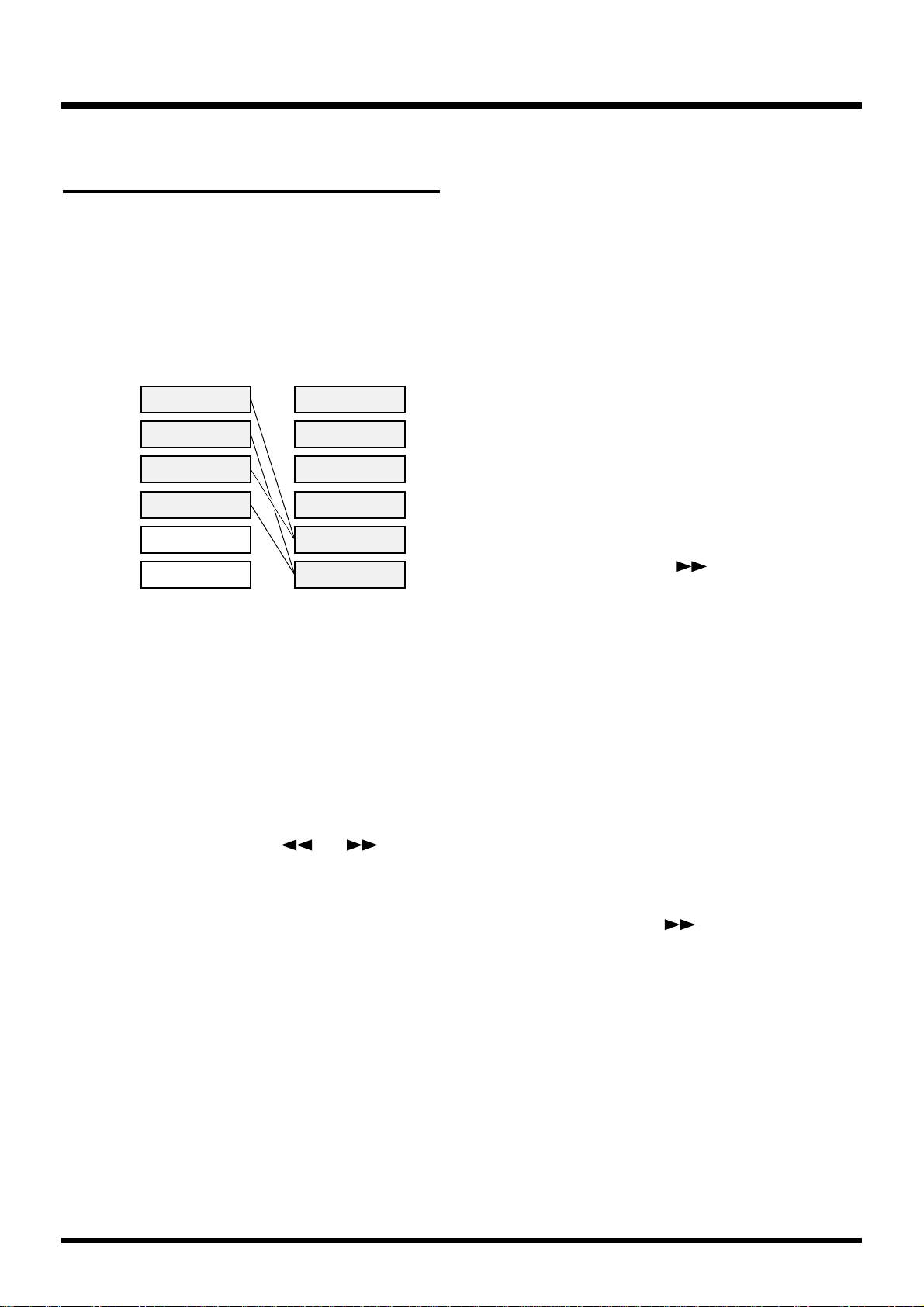
Combining the Contents of
Tracks (Track Bouncing)
You can mix the performances recorded on two or
more tracks and rerecord them onto a different empty
track. This operation is known as track bouncing. It is
a convenient technique to use when you have run out
of free tracks.
In this section, we will mix the performances recorded
on tracks 1–4, and rerecord the result in stereo on
tracks 5 and 6.
* Volume, pan, equalizer, effects, and other settings cannot
be adjusted on tracks mixed with track bouncing. Do not
use track bouncing with tracks to which you want to
apply the equalizer and effects separately.
Specify the Tracks for Playback and
Recording
1. Press [CH EDIT (SELECT)] for Track 5.
2. Press PARAMETER [ ] [ ] until
“Channel Link=” appears in the display.
3. Use the TIME/VALUE dial to select “On.”
4. Press [PLAY (DISPLAY)].
5. While pressing [STOP], press the STATUS buttons
for Tracks 1–4.
The STATUS indicators light green.
6. Press the STATUS buttons for Track 5 (or 6) sever-
al times to let the STATUS indicators light orange.
7. Press [FADER (EDIT)] several times to let the
FADER indicators light green. (Track Mixer)
8. While pressing the STATUS button for Track 5 (or
6), press the SELECT buttons on Channels 1–4.
The SELECT indicators blink green.
9. Usually, the source entering the INPUT 5–6 jacks
is also assigned for recording on Tracks 5–6.
When you want to record only the material on
Tracks 1–4, use the following procedure.
10. Press [FADER (EDIT)].
The FADER indicators light orange. (Input Mixer)
11. While pressing the STATUS button for Track 5 (or
6), press the SELECT buttons on Channels 5 and
6.
The SELECT indicator which had been blinking
orange will go dark.
12. Now Tracks 1–4 can be monitored on Channels
5–6.
Adjust the Pan for Each Track
13. Press the Channel 1 [CH EDIT (SELECT)].
The CH EDIT indicator lights.
14. Press PARAMETER [ ] several times until
“MIX Sw” appears in the display.
15. Rotate the TIME/VALUE dial.
MIX Sw (Mix Switch)
This selects the bus to which the source or track output will be assigned. For this example select “On.”
On: The source or track will be sent to the mix bus.
Set this to “On” when, for example, you simply
want to mix the inputs without recording the
source. However, the sources that are assigned
to the RECORDING bus are disabled.
Off: The source or track will not be assigned to the
mix bus. If it is not assigned to a recording bus
either, then that source/track will not be output
anywhere.
16. Press PARAMETER [ ].
17. Rotate the TIME/VALUE dial.
MIX Pan
This adjusts the pan setting (L63–0–R63) of the signal
sent to the MIX bus and the RECORDING bus.
18. Repeat Steps 13–17 if you wish to make adjust-
ments to other pans.
19. Press [PLAY (DISPLAY)].
Return to Play condition.
20. Press [FADER (EDIT)].
The FADER indicators light green. (Track Mixer)
Performance data 1
Performance data 2
Performance data 3
Performance data 4
Performance data 1
Performance data 2
Performance data 3
Performance data 4
Before Track Bounceing After Track Bounceing
Track 1
Track 2
Performance data 1+3
Performance data 2+4
Track 5
Track 6
Track 3
Track 4
Chapter 3 Multi-Track Recording
60
Page 61

21. Press [PLAY] to begin playback of the song.
22. Adjust the volume balance with the faders for
Channels 1–4. The presently monitored sound
(volume levels, pan) will be recorded to Tracks 5
and 6 just as you hear it. You can raise the volume
as much as possible without causing distortion.
23. Press [STOP] to stop playback of the song.
Record and Check the Content
24. Press [ZERO] to return to the beginning of the
song.
25. While pressing [REC], press the STATUS button
for Track 5 (or 6).
The STATUS indicator blinks red.
26. Press [REC].
The REC indicator blinks red.
27. Press [PLAY].
The PLAY indicator lights green, and starts recording.
28. When recording is finished, press [STOP].
This stops the song.
29. Check the content of the recording. Press [ZERO]
to return to the beginning of the song.
30. Mute (sound is prevented from playing) Tracks
1–4. Press the STATUS buttons for Tracks 1–4.
The STATUS indicators go off.
31. Press [PLAY] to begin playback of the song.
Use the channel faders 5 and the master fader to adjust
the volume to a comfortable level.
Applying Reverb While Track Bouncing
Sometimes you may want to record previously-recorded tracks to another track while apply the effects to
them. Here is how to add reverb to Tracks 1–4 while
bouncing these tracks to Tracks 5 and 6. This can be
convenient when you want to add spatial effects such
as reverb and delay to each track while mixing down.
Select an Effect
1. Press [EFFECT] several times until “EFFECT-1
PRM?” appears in the display.
2. Press [YES].
The number and name of the currently selected effect
will be displayed, and you can select the desired
effect.
3. Use the TIME/VALUE dial to select the effect you
wish to use. Here, select “A00 RV:LargeHall.”
4. After selecting the effect, press [YES].
Specify the Track to Which the Effect is
to be Applied
5. Press [FADER (EDIT)] to light the TR (Track) indi-
cator.
6. Hold down [SHIFT] and press the channel 7
[EFFECT-1 (CH EDIT)].
“EFFECT1=” appears in the display.
7. Press the channel 1 [CH EDIT (SELECT)].
8. Rotate the TIME/VALUE dial.
CONDITION MARKER#
MASTER
INPUT TRACK
AUX
TIME
48
24
4
0
dB
12
Effect Number Effect Name
Chapter 3 Multi-Track Recording
61
Chapter 3
Page 62

EFFECT1 (Effect 1 Send Select Switch)
This sets how the signal is sent to the EFFECT 1 bus.
Here, select “PstFade” (post-fader) to apply reverb to
the sound after the output of the channel fader.
Off: The signal is not sent.
PreFade: The signal before passing through the
channel fader is sent.
PstFade: The signalafter passing through the chan-
nel fader is sent.
* If the effect has been inserted into another channel, the
effect cannot be used. But, the signal from the channel
will be sent to EFFECT bus.
9. Press PARAMETER [ ].
“EFFECT1 Send=” appears in the display.
10. Rotate the TIME/VALUE dial.
EFFECT1 Send (Effect 1 Send Level)
This adjusts the level (0–127) of the signal sent to the
EFFECT 1 bus. Set the initial value to “100.”
11. Press PARAMETER [ ].
“EFFECT1 Pan=” appears in the display.
12. Rotate the TIME/VALUE dial.
13. In the same way as in steps 7–12, make settings so
that reverb is applied to tracks 2–4 as well.
14. Press [PLAY (DISPLAY)].
Return to Play condition.
EFFECT1 Pan (Effect 1 Send Pan)
This adjusts the stereo placement of the signal
(L63–0–R63) sent to the EFFECT 1 bus.
Specify the Tracks for Playback and
Recording
15. Press [CH EDIT (SELECT)] for Track 5.
16. Press PARAMETER [ ] [ ] until
“Channel link =” appears in the display.
17. Use the TIME/VALUE dial to select “On.”
18. Press [PLAY (DISPLAY)].
19. While pressing [STOP], press the STATUS buttons
for Tracks 1–4.
The STATUS indicators light green.
20. Press the STATUS buttons for Track 5 (or 6) to let
the STATUS indicators light orange.
21. While pressing the STATUS button for Track 5 (or
6), press the SELECT buttons on Track Channels
1–4.
The SELECT indicators blink.
22. Press [FADER (EDIT)] several times to light red
the FADER indicator.
23. While pressing the STATUS button for Track 5 (or
6), press the Channel 7 [FX RTN (SELECT)].
The SELECT indicators blink.
24. Usually, the source entering the INPUT 5–6 jacks
is also assigned for recording on Tracks 5. When
you want to record only the material on Tracks
1–4, use the following procedure.
25. Press [FADER (EDIT)].
The FADER indicators light orange. (Input Mixer)
26. While pressing the STATUS button for Track 5,
press the SELECT buttons on Channels 5 and 6.
The SELECT indicator which had been blinking
orange will go dark.
27. Now you have set it up so that you can monitor
Tracks 1–4 and Effect 1 Return on Channels 5–6.
Record and Check the Content
28. Carry out track bouncing by following the proce-
dure described in “Combining the Contents of
Tracks” (p. 60).
Chapter 3 Multi-Track Recording
62
Page 63

Creating a Master Tape
When you finish recording a song, adjust the balance
of each track (equalizer, pan, and volume level), and
using your stereo recorder, record a two-channel
stereo master mix to a stereo cassette, DAT, MD, or
other media. This process is called mixdown.
Prepare for Mixdown
1. Hold down [STOP] and press the STATUS but-
tons for all tracks you want to have mixed down.
The STATUS light green.
2. Press [FADER] several times to light green the
FADER indicator.
3. Use the channel faders and pan knobs on the top
panel to adjust the effect volume and pan of each
track. First determine the volume of the song’s
main tracks (usually the vocals or perhaps a guitar melody). Then, set levels for the other tracks. It
is a good idea to create a balance in which the volume of the other tracks is lower than the main
tracks. Afterwards, make final adjustments to the
pan and equalizer settings for each track as you
listen to the overall mix.
To Record to a Cassette Tape
1. Connect the VS-880EX’s MASTER jacks to the
input jacks of your cassette recorder.
2. Adjust the recording levels for the cassette
recorder. Adjust the output volume with the VS880EX’s master fader, making it as high as possible without causing any input overload on the
recorder. Set the recording levels on the cassette
recorder as high as possible before causing distortion, with the level meter moving a lot.
3. Press [ZERO] on the VS-880EX.
4. Put the cassette recorder in record mode.
5. Press [PLAY] on the VS-880EX to begin playback
of the song.
If you want to fade in or out, use the VS-880EX’s master fader for this.
6. When you have finished recording, stop the cas-
sette recorder.
7. Press [STOP] on the VS-880EX.
8. Listen to the recorded result. Rewind the tape and
play back the recording.
Recording with DAT and MD Recorders
The VS-880EX features two types of digital out connectors, coaxial and optical, either of which is ready to
use. At the factory settings, these connectors are set to
output the same sound as the MASTER jacks.
1. Connect the digital input connector of your digital
recorder with the VS-880EX’s DIGITAL OUT connector.
2. Set your digital recorder to enable it to record dig-
ital signals. Match the recorder’s sample rate to
that of song recorded on the VS-880EX (normally
at 44.1 kHz). Many digital recorders can determine the sample rate automatically. Match the
rates manually only when special settings are necessary.
* There are some DAT recorders that cannot record digital
signals at 44.1 kHz. If such instances, change to an analog connection and set the recorder to enable it to record
analog signals.
3. Press [ZERO] on the VS-880EX.
4. Put the digital recorder in record mode.
5. Press [PLAY] on the VS-880EX.
Playback of the song begins. If you want to fade in or
out, use the VS-880EX’s master fader for this.
6. When you have finished recording, stop the cas-
sette recorder.
7. Press [STOP] on the VS-880EX.
8. Listen to the recorded result. Rewind the tape and
play back the recording.
To Prohibit Digital Copying
When mixing down from the VS-880EX to a DAT
recorder or similar recorder via a digital connection,
you can prevent digital copying of the tape to which
the mixdown has been recorded.
For example, you are allowed to make only one copy
of a regular audio CD onto a DAT tape. Once the digital copy has been made to the DAT tape, you cannot
make further copies onto other digital devices using
digital connections. This function makes DAT tapes
copied digitally from the VS-880EX behave as those
copied digitally from CDs.
Chapter 3 Multi-Track Recording
63
Chapter 3
Page 64

1. Press [SYSTEM] several times until “SYS System
PRM?” appears in the display.
2. Press PARAMETER [ ] several times until
“D.CpyProtect” appears in the display.
3. Rotate the TIME/VALUE dial.
Digital Copy Protect (Digital Copy Protect
Switch)
This setting determines whether or not the digitally
mixed down tape can be later copied digitally. If you
wish to prohibit digital copying, set this “On.”
Off: Digital copying is not prohibited.
On: Digital copying is prohibited.
4. Press [PLAY (DISPLAY)].
Returns to Play condition.
With this procedure, you have made it so that your
digitally mixed master tapes cannot be later copied
digitally onto DAT tapes or similar digital media.
* Some DAT recorders do not conform to SCMS standards
or cannot be connected digitally to CD players. If you are
using such a DAT recorder, then if you set the Digital
Protect Switch to “On,” the digital output from the VS880EX cannot be copied to the DAT recorder. In such
instances, set the Digital Protect Switch to “Off.”
SCMS (Appendices p. 124)
Protecting Songs (Song Protect)
The possibility that a performance saved to the disk
may still be mistakenly overwritten (recorded over), or
that the song itself may be accidentally deleted has
been considered. You can protect songs from being
rewritten in situations such as these. The function is
called Song Protect.
Turning on Song Protect disables the following operations.
• Recording
• Undo (and Redo)
• Song Name, Song Optimize
• Track Edit
• Recording to Sync Tracks
• Creating Tempo Maps
• Song Store
About Effective Use
Song Protect performs the same function as the
protect tab or switch on floppy disks and magnetoptical disks. Thus, even if Song Protect is turned
on, you can still store locate points and mark
points, and carry out operations such as changing
Scenes. However, when you try to save the work
you have done, “Song Protected” appears in the
display, and you are prevented from continuing
any further with the save. However, when you
remove Song Protect, any settings made when
Song Protect was on are lost.
After you have finished all work for the day, turn
on Song Protect immediately before shutting off
the power to the VS-880EX. Furthermore, right
after turning on the power to the VS-880EX at the
beginning the day’s operations, you should immediately turn off Song Protect.
Chapter 3 Multi-Track Recording
64
Page 65

Protecting Performances
1. Make the current song the one to which you want
to apply Song Protect.
2. Press [SONG] several times until “SNG Song
Name/Prtct?” appears in the display.
3. Press [YES].
Song name appears in the display.
4. Press PARAMETER [ ].
“SNG ChangePrtct → On?” appears in the display.
5. Press [YES]. If you wish to cancel, press [NO].
6. “STORE Current?” appears in the display. If you
wish to save the current song and then protect it,
press [YES]. If you wish to protect the state in
which Song Store was last executed without sav-
ing the current song, press [NO].
7. The song will be protected.
“SNG Complete” appears in the display, and return to
Play condition.
To Remove Song Protect
1. Select the song from which you currently want to
remove the protect function.
2. Press [SONG] several times until “SNG Song
Name/Prtct?” appears in the display.
3. Press [YES].
Song name appears in the display.
4. Press PARAMETER [ ].
“SNG ChangePrtct → Off?” appears in the display.
5. Press [YES]. If you wish to cancel, press [NO].
6. Song protect will be disabled.
“SNG Complete” appears in the display, and return to
Play condition.
Selecting a Song (Song Select)
If the VS-1680 contains multiple songs, use the following procedure to select a song.
1. Press [SYSTEM] several times until "Song Select ?"
appears in the display.
2. Press [YES].
3. Use the TIME/VALUE dial to appear the song
name that you wish to select. An asterisk "*" will
be displayed at the beginning of the current song.
4. Press [YES]. "Select Song, Sure?" (Are you sure
that you want to select this song?) will be displayed.
5. Press [YES] again.
6. "STORE Current?" (Store the current song?) will
be displayed. If you wish to save the current song,
press [YES]. If not, press [NO].
7. The song will be selected, and you will return to
the Play Condition.
Chapter 3 Multi-Track Recording
65
Chapter 3
Different types of songs (for the VS-880 and
VS-880EX) are distinguished.
Page 66

The VS-880EX contains effects, allowing up to two stereo effects to be applied
without using any equipment other than the VS-880EX itself.
This chapter explains how to use these internal effects.
Composition of the Effects
The VS-880EX has two effect units which allow two types of effect to be applied
simultaneously (FX1 and FX2). For each channel of the mixer you can specify the
effect which will be used.
Connecting the Effects
Changing the Source Sound Itself (Insert)
The effect is directly added either between each channel’s equalizer and fader or
before the master fader. Connect the effect in this way if you want to use effects
applied to change the output of the sound itself, such as when using distortion
or overdrive effects.
When inserting an effect into one of the channels or into the Master Block, that
effect cannot be used in send/return.
* Depending on the effects used, when mixing with different effects inserted into each
channel, or mixing channels having effects inserted with other channels having no
effects, timing shifts may occur, or you may not be able to achieve the effect you desire.
FX1 FX2
EFFECTS
Level
(Fader)
EQ
(2band, 3band)
FX1SwSend
Level
Pan
FX2SwSend
Level
Pan
AUXSwSend
Level
Pan
Pan
FX1FX1
FX2
MIX bus or REC bus
MIX bus or REC bus
AUX bus
Chapter 4 Using the Internal Effects
66
Page 67

Inserting with Input and Track Channels
1. Press [CH EDIT (SELECT)] for the channel to
which you want to apply the effect.
The CH EDIT indicator lights.
2. Press PARAMETER [ ] [ ] until “FX1
Ins=” appears in the display.
Now you can make settings for effect 1.
3. Select how the effect will be connected. Rotate the
TIME/VALUE dial.
FX1 Ins (Effect 1 Insert Switch)
This sets how the effects are connected.
Insert: Inserts in the between the equalizer and
fader.
InsertL: Inserts in the left channel of the stereo effect.
InsertR: Inserts in the right channel of the stereo
effect.
InsertS: Inserts in the combined left and right chan-
nels of the stereo effect in series.
* When Insert or Insert S is selected, that effect cannot be
used on any other channel. Furthermore, when Insert L or
Insert R is selected, that effect can be inserted on only one
other channel.
4. Press PARAMETER [ ].
“FX1 Ins Send=” appears in the display.
5. Rotate the TIME/VALUE dial.
Ins Send (Insert Send Level)
This adjusts the level of the signal (0–127) sent to the
Insert effect. Set the initial value to “100.”
6. Press PARAMETER [ ].
“FX1 Ins Rtn=” appears in the display.
7. Rotate the TIME/VALUE dial.
Ins Rtn (Insert Return Level)
This adjusts the level of the signal (0–127) returned
from the Insert effect. Set the initial value to “100.”
8. At this point, you are ready to insert FX1 into the
selected channel. Press [PLAY (DISPLAY)].
Return to Play condition.
9. You can insert FX2 in the same way. In this case,
perform step 2 so that “FX2 Ins=” is displayed.
* Steps 4–7 can be adjusted only when the effect is being
used as an insertion effect.
Inserting an Effect into the Master Block
This inserts the effect into the MASTER Out. After the
mix for each channel is completed, the entire song is
put through the compressor, which is convenient at
such times as when you listen to the total volume
while mixing down.
1. Hold down [SHIFT] and press [EDIT (FADER)].
2. Press PARAMETER [ ] [ ] until “MST
FX1 INS Sw=” appears in the display.
If FX1 has been inserted into another channel, the display will indicate “MST FX1 INS Sw=—” (the setting
cannot be made).
3. Rotate the TIME/VALUE dial.
CONDITION MARKER#
MASTER
INPUT TRACK
AUX
TIME
48
24
4
0
dB
12
EQ
(2band, 3band)
FX
Insert
L
R
L
R
EQ
(2band, 3band)
FX
Insert L
LL
EQ
(2band, 3band)
FX
Insert R
RR
EQ
(2band, 3band)
FX
Insert S
L
R
L
R
Chapter 4 Using the Internal Effects
67
Chapter 4
Page 68

MST FX1 INS Sw (Master Effect 1 Insert Switch)
This sets how the effects are connected.
Off: There is no Insert.
On: Inserts in both channels of the stereo effect.
4. Press PARAMETER [ ].
“MST FX1 Ins Send=” appears in the display.
5. Rotate the TIME/VALUE dial.
MST FX1 Ins Send (Master Effect 1 Insert Send Level)
This adjusts the level of the signal (0–127) sent to the Insert effect. Set the initial
value to “100.”
6. Press PARAMETER [ ].
“MST FX1 Ins Rtn=” appears in the display.
7. Rotate the TIME/VALUE dial.
MST FX1 Ins Rtn (Master Effect 1 Insert Return Level)
This adjusts the level of the signal (0–127) returned from the Insert effect. Set the
initial value to “100.”
8. Press [PLAY (DISPLAY)].
Return to Play condition.
9. You can insert FX2 in the same way. In this case, perform step 1 so that
“MST FX2 INS Sw=” is displayed.
Adding the Sound with the Effect Applied to the Direct Sound (Send/Return)
When adding the sound with effect to the direct sound, such as is done with
reverb or delay, use the EFFECT bus.
With some effects, while you can have output of both the direct sound and effect
sound, it’s usually better to have the effect sound output separately. The direct
sound and effect sound are adjusted with each channel fader. The present signal
flow is shown below.
CONDITION MARKER#
MASTER
INPUT TRACK
AUX
TIME
48
24
4
0
dB
12
Level
(Fader)
EQ
(2band, 3band)
FX1SwSend
Level
Pan
FX2SwSend
Level
Pan
AUXSwSend
Level
Pan
Pan
FX1
FX2
MIX bus or REC bus
MIX bus or REC bus
MIX bus or REC bus
AUX bus
Chapter 4 Using the Internal Effects
68
Page 69

Settings for Each Channel
1. Press [CH EDIT (SELECT)] for the channel to
which you want to apply the effect.
The CH EDIT indicator lights.
2. Hold down [SHIFT] and press the channel 7
[EFFECT-1 (CH EDIT)].
The upper line of the display will indicate “EFFECT
1,” and you can make settings for effect 1.
3. Select how the effect will be connected. Rotate the
TIME/VALUE dial.
EFFECT 1 (Effect 1 Send Select Switch)
This selects the how the signal is sent to the EFFECT 1
bus (send).
Off: The signal is not sent.
PreFade: The sound before passing through the
channel fader is sent.
PstFade: The sound after passing through the
channel fader is sent.
4. Press PARAMETER [ ].
“EFFECT1 Send=” appears in the display.
5. Rotate the TIME/VALUE dial.
EFFECT1 Send (Effect 1 Send Level)
This adjusts the volume level of the signal (0–127) sent
to the EFFECT 1 bus. Set the initial value to “100.”
6. Press PARAMETER [ ].
“EFFECT1 Pan=” appears in the display.
7. Rotate the TIME/VALUE dial.
FFFECT1 Pan (Effect 1 Send Pan)
This adjusts the stereo placement of the signal
(L63–0–R63) sent to the EFFECT 1 bus.
8. Press [PLAY (DISPLAY)].
Return to Play condition.
9. You can use the same method to make settings for
each channel for FX2 as well. In this case, hold
down [SHIFT] and press channel 8 [EFFECT-2
(CH EDIT)] in step 2.
Master Block Settings 1
(Send Level Adjustment)
You can adjust the balance of the total effect send level
for each effect with the effect send level and send pan
settings that are assigned to each individual channel
left as they are.
* If FX1 has been inserted into another channel, or if it has
been inserted into the MASTER OUT jacks, these displays will not appear (settings cannot be made).
1. Hold down [SHIFT] and press [EDIT (FADER)].
2. Press PARAMETER [ ] [ ] until “MST
FX1 SND Lev=” appears in the display.
3. Rotate the TIME/VALUE dial.
MST FX1 SND Lev (Master Effect 1 Send Level)
This adjusts the total volume level of the signal (0–127)
sent to the effect. Set the initial value to “100.”
4. Press PARAMETER [ ].
“MST FX1 SND Bal=” appears in the display.
5. Rotate the TIME/VALUE dial.
MST FX1 SND Bal
(Master Effect 1 Send Balance)
This adjusts the balance (L63–0–R63) of the total signal
sent to the effect. Set the initial value to “0” (center).
6. Press [PLAY (DISPLAY)].
Return to Play condition.
7. You can adjust the send level in the same way for
FX2 as well. In this case, access the “MST FX2
SND Lev=” display in step 2.
Master Block Settings 2
(Return Level Adjustment)
Use the channel faders and pan knobs on the top panel
to adjust the effect on volume (return level).
1. Press [FADER (EDIT)] several times until the
FADER indicator lights red.
2. Press the channel 7 [EFFECT-1 (CH EDIT)].
The CH EDIT indicator lights.
CONDITION MARKER#
MASTER
INPUT TRACK
AUX
TIME
48
24
4
0
dB
12
Chapter 4 Using the Internal Effects
69
Chapter 4
Page 70

3. Press PARAMETER [ ] [ ] until “RTN
FX1 RTNLev=” appears in the display.
4. Rotate the TIME/VALUE dial.
RTN FX1 RTNLev (Master Effect 1 Return Level)
Adjust the return level (0–127) of the effect sound. Set
the initial value to “100.”
5. Press PARAMETER [ ].
“RTN FX1Bal=” appears in the display.
6. Rotate the TIME/VALUE dial.
RTN FX1 RTNBal
(Master Effect 1 Return Balance)
Adjust the left/right balance (L63–0–R63) of the effect
sound. Set the initial value to “0” (center).
7. Press [PLAY (DISPLAY)].
Return to Play condition.
8. You can make master block settings in the same
way for FX2 as well. For step 2 in this case, press
channel 8 [CH EDIT (EFFECT-2)]. At this time, the
channel faders on the top panel will function as
follows.
Selecting Effects (Patch)
An effect settings is referred to as a patch. The VS880EX provides 210 (A00–A99, B00–B99, C00–C09)
read-only effects (Preset Patches) and 100 (U00-U99)
read and write effects (User Patches). Please take a
moment to check these effects.
* If used in combination with the Vari Pitch function (p.
152), delay times may change somewhat, and for distortion effects (distortion, overdrive, etc.), there may be some
change in the quality of the tone.
* With some of the effects, you may not want the direct
sound output, or other special setting may be required.
Please refer to “Algorithm List” (Appendices p. 26) when
making these settings.
1. Press [EFFECT] several times until “EFFECT-1
PRM?” appears in the display.
2. Press [YES].
The number and name of the currently selected effect
will be displayed, and you will be able to select the
effect.
3. Use the TIME/VALUE dial to select the effect you
wish to use.
4. After selecting the effect, press [YES].
5. Check the effect to make sure that the sound is
actually being played. Repeat Steps 3–5 for any
other patches whose effects you want to confirm.
* Noise may occur with some types of effects when the effect
patches are selected.
If the audio device is at high volume levels, then protect
the speakers and other device from damage, turn off the
[EFFECTS ON/OFF] or lower the volume on the audio
device before selecting the effect patches.
6. After you have checked the patches, press [PLAY
(DISPLAY)].
Return to Play condition.
7. You can use the same procedure to hear the effect
of FX2 as well. For step 1 in this case, make the
display read “EFFECT-2 PRM?”
ST IN
Balance
FX1
Balance
FX2
Balance
ST IN
Level
FX1
Level
FX2
Level
CONDITION MARKER#
MASTER
INPUT TRACK
AUX
TIME
48
24
4
0
dB
12
Effect Number Effect Name
Chapter 4 Using the Internal Effects
70
Page 71

* Patches using the following algorithms can not be selected
for FX2. A horizontal line is drawn through the effect
name in such cases. Please select patches using these algorithms for use with FX1.
• Reverb
• Gated Reverb
• Vocorder 2
• Voice Transformer
Creating New Effects Sounds
When creating a new effect, first select the existing
patch whose sound is closest to the “image” of the
patch you wish to create, and then alter that patch settings.
Since changes to effects settings are temporary, they
are lost once you select another patch or recall a different Scene. When saving changed effects settings, either
save them to the User Patches or store the mixer settings as a Scene.
1. Using the procedure described in “Selecting
Effects (Patch)” (p. 70), call up the patch contain-
ing the effect on which you will base your new
effect.
2. Press PARAMETER [ ].
When you select a patch with an algorithm in which
the effect can be turned on and off, the following
screen is displayed.
An effect block which is currently ON is displayed as
“ ■” and an effect block which is currently OFF is displayed as “ ”
3. Use CURSOR [ ] [ ] to move the cursor to
the effect block that you wish to turn on/off.
4. Rotate the TIME/VALUE dial. If an effect block is
turned off, parameters related to that effect cannot
be set.
5. Use PARAMETER [ ] [ ] to access the
parameter that you wish to adjust.
6. Rotate the TIME/VALUE dial. Check the effect.
7. Repeat the Steps 5–6 to create new effects sounds.
8. Press PARAMETER [ ] several times until
“FX1 Nam=” appears in the display.
9. Assign a patch name. Use CURSOR [ ] [ ]
so that the character you wish to change is blinking. Use the TIME/VALUE dial to select the
desired character. A name of up to 12 characters
can be assigned.
10. Save the effect. If you wish to keep the effect set-
tings that you have modified, you must save the
settings either as a User Patch or as mixer settings
in a Scene. If you wish to use the effect settings in
another song, save them as a User Patch. If you
wish to use the effect settings in the currently
selected song, save them as a Scene.
About Algorithms
An algorithm determines the composition or
structure of an effect. The VS-880EX features 34
different algorithms. The settings for the effects in
each patch use at least one of these algorithms.
Check the algorithms used in each patch in
“Preset Patch List” (Appendices p. 19). For details
on each algorithm, refer to “Algorithm List”
(Appendices p. 26).
CONDITION MARKER#
MASTER
INPUT TRACK
AUX
TIME
48
24
4
0
dB
12
Block
(Off)
Block
(On)
Block
(On)
Chapter 4 Using the Internal Effects
71
Chapter 4
Convenient Operations
•You can hold down [SHIFT] and press
[EFFECT] to alternate between the Effect Select
page, Effect Name page, and Effect On/Off
page.
• In the Effect On/Off page, you can move directly to the setting page for the effect that is blinking by pressing PARAMETER [ ].
• In the Effect Setting page, you can display the
parameters of the next effect block by holding
down [SHIFT] and pressing PARAMETER
[ ]. To display the parameters of the previous effect block, hold down [SHIFT] and press
PARAMETER [ ].
Page 72

When Saving to User Patches
When you save effect settings to a User Patch, the User
Patch that had previously been in that location is lost.
At the time of purchase, the effects in the VS-880EX’s
User Patches are the same as those stored in the Preset
Patches.
1. Press PARAMETER [ ].
“Save User Patch?” appears in the display.
2. Press [YES].
3. Rotate the TIME/VALUE dial to select the desti-
nation patch number (U00–U99).
4. Press [YES].
When the User Patch has been saved, the display will
indicate “Complete.”
5. Press [PLAY (DISPLAY)].
Return to Play condition.
When Storing to a Scene
For more detailed information, please refer to
“Recording the Current Condition of the Mixer
(Scene)” (p. 73).
1. Press [SCENE].
The SCENE indicator lights.
2. Press the LOC buttons ([1/5]–[4/8]) whose indi-
cators are not blinked. For example, if you want to
store the settings to Scene 1, then press [1/5]. If
you wish to store the settings in Scene 5, hold
down [SHIFT] and press [1/5].
3. Hold down [SHIFT] and press [STORE (ZERO)].
“STORE OK?” appears in the display.
4. Press [YES].
5. Press [SCENE] once more.
The SCENE indicator will go dark. If you wish to halt
the registration procedure, press [SCENE] before step
2.
6. Press [PLAY (DISPLAY)].
Return to Play condition.
About Effect Levels
Many algorithms include parameters for effect
level, which adjusts the output level of the effect
sound, and direct level, which adjusts the output
level of the direct sound. When these parameters
are preceded by a minus sign, the phase is inverted.
The direct level of the Preset Patches, which were
created with careful consideration given to the
connection to the EFFECT bus, is set to “0.” When
inserting an effect into a channel, raise the direct
level. To determine the type for each Preset Patch,
please refer to “Preset Patch List” (Appendices p.
19).
Chapter 4 Using the Internal Effects
72
Page 73

With the VS-880EX, there are two functions to recall
mixer settings easily. One is refered to as the Scene,
and the other one is referred to as the EZ Routing.
According to the circumstances, please use each function.
Scene:
A Scene stores the current mixer settings, include that
setting values in a song. For example, during mixdown, you can create a number of mixes with different
settings for volume, pan, equalizer, etc., and compare
those mixes, each one with all of its settings preserved.
This is a very convenient feature.
EZ Routing:
The VS-880EX can store settings related to its mixer
connections. These include settings for routing of
inputs to tracks for recording, for determining where
signals are output, and for determining which output
is to be monitored. For example, these settings, which
stay the same, regardless of the song, include playback
and recording track settings during track bouncing,
and effects settings during mixdown. This makes EZ
Routing convenient in such situations.
Recording the Current Condition of
the Mixer (Scene)
Up to 8 sets of settings, values included, that define
the total condition of the mixer can be stored for each
song, and can be recalled instantly at the touch of a
button. A stored set of mixer settings is called a
Scene. A Scene includes not only the volume and pan
settings, but also connections (e.g., the track to which
the source from the INPUT 1 jack is recorded), V-track
settings (the track to which each is recorded), and
effects (such as the selection of the effect to be
applied). This feature is convenient when you want to
compare different balances of volume, pan, equalizer,
and other settings during mixdown.
Storing a Scene
1. Press [SCENE].
The SCENE indicator lights.
2. At this point, the LOC button ([1/5]–[4/8]) act to
store or recall scene.
Indicators light for any LOC buttons ([1/5]–[4/8])
storing scene.
3. Press a LOC button ([1/5]–[4/8]) whose button
indicator does not light. For example, if you want
to record to Scene 1, then press [1/5]. If you wish
to store the settings in Scene 5, hold down
[SHIFT] and press [1/5].
4. Press [SCENE] once more..
The SCENE indicator will go dark. If you wish to halt
the registration procedure, press [SCENE] before step
3.
Recalling a Scene
1. Press [Stop].
* You cannot select a Scene during recording or playback.
2. Press [SCENE].
The SCENE indicator lights.
3. At this point, the LOC button ([1/5]–[4/8]) act to
store or recall scene. Indicators light for any LOC
buttons ([1/5]–[4/8]) storing scene.
4. Press a LOC button ([1/5]–[4/8]) whose button
indicator lights. For example, if you want to recall
the Scene 1, then press [1/5]. If you wish to recall
Scene 5, hold down [SHIFT] and press [1/5].
5. Press [SCENE] once more.
The SCENE indicator will go dark. If you wish to halt
the recall procedure, press [SCENE] before step 4.
Recalling a Scene Without Affecting
the Current Fader Values
When a Scene is recalled, the fader values will change
to the recalled settings. However, the positions of the
top panel’s faders themselves do not change. This
means that the locations of the faders will not match
their actual values.
If you want just the fader values to remain unchanged
when you recall a Scene, make the following settings.
1. Press [SYSTEM] several times until “SYS
Scene/Auto Mix ?” appears in the display.
2. Press [YES].
“SYS Scene Mode=” appears in the display.
3. Use the TIME/VALUE dial to select “KeepF.”
Chapter 5 Storing Mixer Settings
73
Chapter 5
Page 74

SYS Scene Mode
This setting determines the fader settings when a
Scene is recalled.
All: This changes the mixer settings to those of
the Scene being recalled. In this case, when a
Scene is recalled, the location of the faders on
the top panel may no longer match the actual
fader settings.
KeepF: This changes the mixer settings to those of
the Scene being recalled, with the exception
of the fader settings. This means that even
when a Scene is recalled, fader settings will
still match the fader positions on the top
panel.
4. Press [PLAY (DISPLAY)].
Return to Play condition.
Deleting a Scene
1. Press [SCENE].
The SCENE indicator lights.
2. The indicators for the LOC buttons ([1/5]–[4/8])
to which scene are stored then light.
3. Hold down [CLEAR], and press the LOC button
([1/5]–[4/8]) for the scene that you wish to clear.
For example if you wish to clear the mixer settings
that were stored in scene 1, hold down [CLEAR]
and press [1/5]. If you wish to clear the mixer set-
tings that were stored in scene 5, hold down both
[CLEAR] and [SHIFT], and press [1/5].
4. Press [SCENE] once more.
The SCENE indicator will go dark. If you wish to halt
the Clear procedure, press [SCENE] before step 3.
Making Mixer Settings
Automatically (EZ Routing)
Settings related to mixer connections, including settings for routing of inputs to tracks for recording, for
determining where signals are output, and for determining which output is to be monitored can be stored
and recalled easily with the VS-880EX. This is referred
to as EZ Routing.
For example, when setting tracks to be played back or
recorded during track bouncing, or when dealing with
effects settings during mixdown there are settings
which remain the same, regardless of the song. In such
situations, by preparing stored mixer settings to be
recalled later, you can easily get the most effective and
appropriate mixer settings for each parameter.
At the time of purchase, your VS-880EX came with
three read-only EZ Routing settings (Preset Routings)
already configured. In addition to these, the VS-880EX
offers 29 rewritable EZ Routing settings (User
Routings), allowing you to make changes to the settings provided and then save these to the User
Routings.
Easy Routing can be used in the following situations.
Recording:
When you want to record the performance input via
the INPUT jacks.
Mixdown:
When you want adjust the balance of each track or to
record a MD player or similar input in two-channel
stereo.
Bouncing:
When recording the performance data from multiple
tracks onto a number of other tracks.
Easy Routing can be set in the following two ways for
recording, mixdown, and track bouncing, respectively.
Template:
Recall a read-only setting (preset routing) or a previously stored setting (user routing) without change.
Step Edit:
Reply to questions in dialog format to make settings in
a logical sequence.
Chapter 5 Storing Mixer Settings
74
Page 75

Recalling Recording Settings
(Recording/Template)
Select this when you want to record the performance
input via the INPUT jacks. Recall a preset routing
(recording) which has been pre-registered when the
VS-880EX was shipped.
1. Press [EZ ROUTING] several times until “EZR
Recording ?” appears in the display.
2. Press [YES].
“EZR Use Template” (do you wish to apply the template?) appears in the display.
3. Press [YES].
4. When the routing has been recalled, “Complete”
appears in the display, and return to Play condi-
tion. At this time, the mixer settings will be as fol-
lows.
INPUT Jack Recording Track
INPUT 1 1
INPUT 2 2
INPUT 3 3
INPUT 4 4
INPUT 5 5
INPUT 6 6
DIGITAL IN1 (7) 7
DIGITAL IN1 (8) 8
Display (parameter name) Input Track
Mixer Mixer
ATT current value current value
Phase current value current value
MIX Sw Off On
MIX Level 100 100
MIX Pan 0 (IN7=InsertL, IN8=InsertR) 0
V.Track - currently
selected
V-track
EQ Switch On EQL (Gain) 0 dB EQL (Frequency) 300 Hz EQM (Gain) 0 dB EQM (Q) 0.5 EQM (Frequency) 1.4 kHz EQH (Gain) 0 dB EQH (Frequency) 4 kHz FX1 Ins
Off (IN3=InsertL, IN4=InsertR)
Off
FX2 Ins Off Off
AUX Sw Off Off
Display (parameter name) Input Track
Mixer Mixer
Fader Link Off Off
Channel Link Off Off
EFFECT1 Off Off
EFFECT2 Off Off
Display (parameter name) Master Block
Master Sel MIX
EQ Mode 3band
Direct Out Off
Master FX1 Ins Master FX2 Ins -
Display (parameter name) Effect
FX1 Sel A96:DualComp/Lim
FX2 Sel A96:DualComp/Lim
Recalling Track Bouncing Settings
(Bouncing/Template)
Select this when recording the performance data from
multiple tracks onto a number of other tracks. Recall a
preset routing (bouncing) which has been pre-registered when the VS-880EX was shipped.
1. Press [EZ ROUTING] several times until “EZR
Bouncing ?” appears in the display.
2. Press [YES].
“EZR Use Template” (do you wish to apply the template?) appears in the display.
3. Press [YES].
4. When the routing has been recalled, “Complete”
appears in the display, and return to Play condition. At this time, the mixer settings will be as follows.
Recording Track: TRACK 7–8
Input jack/track/effect assigned to the recording
track: INPUT 1–6
DIGITAL IN1 (7/8)
TRACK 1–6
FX1 Return
FX2 Return
Chapter 5 Storing Mixer Settings
75
Chapter 5
Page 76

Display (parameter name) Input Track
Mixer Mixer
ATT current value current value
Phase current value current value
MIX Sw Off O
(TRd=On)
MIX Level 100 100
(TRd Ofs Level=100)
MIX Pan 0 0
(TR7=L63,
TR8=R63,
TRd Ofs Bal=0)
V.Track - Currently
selected
V-track
EQ Switch - On
EQL (Gain) - 0 dB
EQL (Frequency) - 300 Hz
EQM (Gain) - 0 dB
EQM (Q) - 0.5
EQM (Frequency) - 1.4 kHz
EQH (Gain) - 0 dB
EQH (Frequency) - 4 kHz
FX1 Ins Off Off
FX2 Ins Off Off
AUX Sw Off Off
Fader Link Off Off
Channel Link Off Off
EFFECT1 PstFade PstFade
(TRd=Off)
EFFECT1 Send 100 100
EFFECT1 Pan 0 0
EFFECT2 PstFade PstFade
(TRd=Off)
EFFECT2 Send 0 0
EFFECT2 Pan 0 0
Display (parameter name) Return Mixer
StereoIn Off
FX1 RTN Lev 100
FX1 RTN Bal 0
FX2 RTN Lev 100
FX2 RTN Bal 0
Display (parameter name) Master Block
Master Sel MIX
EQ Mode 3band
Direct Out Off
Master FX1 Ins Off
Master FX2 Ins Off
Display (parameter name) Effect
FX1 Sel A00:LargeHall
FX2 Sel A22:Short Dly
Recalling Mixdown Settings
(Mixdown/Template)
Select this when you want adjust the balance of each
track or to record a MD recorder or similar input in
two-channel stereo. Recall a preset routing (mixdown)
which has been pre-registered when the VS-880EX
was shipped.
1. Press [EZ ROUTING] several times until “EZR
Mix Down ?” appears in the display.
2. Press [YES].
“EZR Use Template” (do you wish to apply the template?) appears in the display.
3. Press [YES].
4. When the routing has been recalled, “Complete”
appears in the display, and return to Play condition. At this time, the mixer settings will be as follows.
Playback Track: TRACK 1–8
Input jack/track/effect assigned to the master out:
INPUT 1–6
DIGITAL IN1 (7/8)
TRACK 1–8
FX1 Return
FX2 Return
Display (parameter name) Input Track
Mixer Mixer
ATT current value current value
Phase current value current value
MIX Sw On On
MIX Level 100 100
MIX Pan 0 (IN7=L63, IN8=R63) 0
V.Track - Currently
selected
V-track
EQ Switch On On
EQL (Gain) 0 dB 0 dB
EQL (Frequency) 300 Hz 300 Hz
EQH (Gain) 0 dB 0 dB
EQH (Frequency) 4 kHz 4 kHz
FX1 Ins Off Off
FX2 Ins Off Off
AUX Sw (AUX Switch) Off Off
Fader Link Off Off
Chapter 5 Storing Mixer Settings
76
Page 77

Display (parameter name) Input Track
Mixer Mixer
Channel Link Off Off
EFFECT1 PstFade PstFade
EFFECT1 Send 100 100
EFFECT1 Pan 0 0
EFFECT2 PstFade PstFade
EFFECT2 Send 100 100
EFFECT2 Pan 0 0
Display (parameter name) Return Mixer
StereoIn Off
FX1 RTN Lev 100
FX1 RTN Bal 0
FX2 RTN Lev 100
FX2 RTN Bal 0
Display (parameter name) Master Block
Master Sel MIX
EQ Mode 2band
Direct Out Off
Master FX1 Ins Off
Master FX2 Ins Off
Display (parameter name) Effect
FX1 Sel A00:LargeHall
FX2 Sel A22:Short Dly
Storing Recording Settings
(Recording/Step Edit)
Select this when you want to record the performance
input via the INPUT jacks.
1. Press [EZ ROUTING] several times until “EZR
Recording ?” appears in the display.
2. Press [YES].
“EZR Use Template” (do you wish to apply the template?) appears in the display.
3. Press [NO].
4. “REC Track =” appears in the display. Specify the
track on which you will record. Press the STATUS
button of the track that you wish to record. The
STATUS indicator will blink red. Each time you
press the STATUS button, you will cycle between
recording and not recording. You can rotate the
TIME/VALUE dial to select the V-track that you
wish to record.
5.
Press PARAMETER [ ]. You can return to the
previous screen by pressing PARAMETER [ ].
6. “TR* Link=” (“*” is the displayed track) appears
in the display. Specify the tracks for which you
will turn Channel Link ON. Press the STATUS
button of the tracks for which you wish to turn
Channel Link ON, and rotate the TIME/VALUE
dial.
7. Press PARAMETER [ ]. You can return to
the previous screen by pressing PARAMETER
[].
CONDITION MARKER#
MASTER
INPUT TRACK
AUX
TIME
48
24
4
0
dB
12
Display of tracks for recording
Current track selected for setting
CONDITION MARKER#
MASTER
INPUT TRACK
AUX
TIME
48
24
4
0
dB
12
Chapter 5 Storing Mixer Settings
77
Chapter 5
Page 78

8. “IN* Link=” (“*” is the displayed input) appears
in the display. Specify the inputs for which you
will turn Channel Link ON. Press the SELECT
(CH EDIT) button of the inputs for which you
wish to turn Channel Link ON, and rotate the
TIME/VALUE dial.
9.
Press PARAMETER [ ]. You can return to the
previous screen by pressing PARAMETER [ ].
10. “IN* to =” appears in the display. Specify which
source is to be recorded on each track. First press
the source input SELECT (CH EDIT) button, then
press the track STATUS button for the track to
which the source is to be recorded.
You can also use the TIME/VALUE dial to select the
recording destination track. If you select “---,” that
input will not be output anywhere (i.e., the sound will
not be heard). If you select “MIX,” the source will be
assigned to a mix bus (i.e., sound will be heard but
will not be recorded).
* Sources that have Channel Link set to “On” cannot be
recorded to tracks on which Channel Link is set to “Off”
with the EZ Routing.
11.
Press PARAMETER [ ]. You can return to the
previous screen by pressing PARAMETER [ ].
12. “IN* Pan =” appears in the display. Adjust the
pan of the source. Press the SELECT (CH EDIT)
button for the input whose pan you wish to
adjust, and use the TIME/VALUE dial. You can
also use the pan knobs on the top panel to adjust
the pan.
* When Channel Link is on, adjust the Offset Balance of the
sources. (p. 151)
13.
Press PARAMETER [ ]. You can return to the
previous screen by pressing PARAMETER [ ].
14. “IN* Level =” appears in the display. Adjust the
level of the source. Press the SELECT (CH EDIT)
button for the input whose level you wish to
adjust, and use the TIME/VALUE dial. You can
also use the channel faders on the top panel to
adjust the level.
* When Channel Link is on, adjust the Offset Level of the
sources. (p. 150)
15.
Press PARAMETER [ ]. You can return to the
previous screen by pressing PARAMETER [ ].
16. “Use EFFECT1 ?” appears in the display. If you
wish to use effect 1, press [YES], and proceed to
step 17. If you do not wish to use effect 1, press
[NO] and proceed to step 31.
17. The effect patch will be displayed. Use the
TIME/VALUE dial to select the effect patch that
you wish to use.
18.
Press PARAMETER [ ]. You can return to the
previous screen by pressing PARAMETER [ ].
CONDITION MARKER#
MASTER
INPUT TRACK
AUX
TIME
48
24
4
0
dB
12
CONDITION MARKER#
MASTER
INPUT TRACK
AUX
TIME
48
24
4
0
dB
12
CONDITION MARKER#
MASTER
INPUT TRACK
AUX
TIME
48
24
4
0
dB
12
CONDITION MARKER#
MASTER
INPUT TRACK
AUX
TIME
48
24
4
0
dB
12
Chapter 5 Storing Mixer Settings
78
Page 79

19. “IN* FX1 Ins=” appears in the display. Rotate the
TIME/VALUE dial. If you wish to insert effect 1,
select either “Ins,” “InsL,” “InsR,” or “InsS,” and
proceed to step 20. If you wish to use effect 1 in a
send/return configuration, select “Off” and pro-
ceed to step 23.
20. “IN* InsSnd =” appears in the display. Use the
TIME/VALUE dial to adjust the insert send level.
21.
Press PARAMETER [ ]. You can return to the
previous screen by pressing PARAMETER [ ].
22. “IN* InsRtn =” appears in the display. Use the
TIME/VALUE dial to adjust the insert return
level.
23.
Press PARAMETER [ ]. You can return to the
previous screen by pressing PARAMETER [ ].
24. “IN* FX1Snd=” appears in the display. Rotate the
TIME/VALUE dial. If you wish to send the input
to the effect 1 bus, select either “Pre” or “Pst,” and
proceed to step 25. If you do not wish to send the
input to the effect 1 bus, select “Off,” and proceed
to step 31.
25.
Press PARAMETER [ ]. You can return to the
previous screen by pressing PARAMETER [ ].
26. “IN* SndLev =” appears in the display. Use the
TIME/VALUE dial to adjust the send level. If in
step 19 you selected either “Ins,” “InsL,” “InsR,”
or “InsS,” the sound already processed by the
effect will be sent to the effect bus. (It will not be
re-input to effect 1.)
27.
Press PARAMETER [ ]. You can return to the
previous screen by pressing PARAMETER [ ].
28. “IN* SndPan” appears in the display. Use the
TIME/VALUE dial to adjust the send pan.
29.
Press PARAMETER [ ]. You can return to the
previous screen by pressing PARAMETER [ ].
30. “REC FX1 =” appears in the display. If you wish
to record the effect which you are using in a
send/return configuration, press the STATUS
button for the recording destination track.
However if in step 19 you selected either “Ins,”
“InsL,” “InsR,” or “InsS,” this display will not
appear. (The sound with the inserted effect will be
recorded.)
31.
Press PARAMETER [ ]. You can return to the
previous screen by pressing PARAMETER [ ].
32. “Use EFFECT2 ?” appears in the display. If you
wish to use effect 2 press [YES], and make settings
for effect 2 as described in steps 17–30. If you do
not wish to use effect 2, press [NO] and proceed
to step 33.
33. “IN* AUX Snd” appears in the display. Rotate the
TIME/VALUE dial. If you wish to send the input
to the AUX bus, select either “Pre” or “Pst,” and
proceed to step 34. If you do not wish to send the
input to the AUX bus, select “Off,” and proceed to
step 31.
34.
Press PARAMETER [ ]. You can return to the
previous screen by pressing PARAMETER [ ].
35. “IN* SndLev =” appears in the display. Use the
TIME/VALUE dial to adjust the send level.
CONDITION MARKER#
MASTER
INPUT TRACK
AUX
TIME
48
24
4
0
dB
12
CONDITION MARKER#
MASTER
INPUT TRACK
AUX
TIME
48
24
4
0
dB
12
CONDITION MARKER#
MASTER
INPUT TRACK
AUX
TIME
48
24
4
0
dB
12
CONDITION MARKER#
MASTER
INPUT TRACK
AUX
TIME
48
24
4
0
dB
12
Chapter 5 Storing Mixer Settings
79
Chapter 5
Page 80

36.
Press PARAMETER [ ]. You can return to the
previous screen by pressing PARAMETER [ ].
37. “IN* SndPan” appears in the display. Use the
TIME/VALUE dial to adjust the send pan.
38.
Press PARAMETER [ ]. You can return to the
previous screen by pressing PARAMETER [ ].
39. “Master Sel=” appears in the display. Use the
TIME/VALUE dial to select the bus (MIX, AUX,
FX1, FX2, REC) that you wish to output from the
MASTER jacks.
40.
Press PARAMETER [ ]. You can return to the
previous screen by pressing PARAMETER [ ].
41. “EQ Sel=” appears in the display. Rotate the
TIME/VALUE dial.
42.
Press PARAMETER [ ]. You can return to the
previous screen by pressing PARAMETER [ ].
43. “Direct Out =” appears in the display. Rotate the
TIME/VALUE dial. If you do not wish to use
Direct OUT, select “Off.” If you wish to output
tracks 1–4, select “1-4.” If you wish to output
tracks 5–8, select “5-8.”
44.
Press PARAMETER [ ]. You can return to the
previous screen by pressing PARAMETER [ ].
45. “FX1 MstIns=” appears in the display. Rotate the
TIME/VALUE dial. If you wish to insert effect 1
into the master out, select “On.” If not, select
“Off.” If effect 1 has been inserted in another
channel, the display will indicate “—” and this
item cannot be set.
46.
Press PARAMETER [ ]. You can return to the
previous screen by pressing PARAMETER [ ].
47. “FX2 MstIns=” appears in the display. Rotate the
TIME/VALUE dial. If you wish to insert effect 2
into the master out, select “On.” If not, select
“Off.” If effect 2 has been inserted in another
channel, the display will indicate “—” and this
item cannot be set.
48.
Press PARAMETER [ ]. You can return to the
previous screen by pressing PARAMETER [ ].
49. “Change Routing ?” appears in the display. Press
[YES]. When the routing has been finalized,
“Complete” appears in the display, and you will
return to Play condition. If you decide to discard
the routing that was set, press [NO].
CONDITION MARKER#
MASTER
INPUT TRACK
AUX
TIME
48
24
4
0
dB
12
CONDITION MARKER#
MASTER
INPUT TRACK
AUX
TIME
48
24
4
0
dB
12
CONDITION MARKER#
MASTER
INPUT TRACK
AUX
TIME
48
24
4
0
dB
12
CONDITION MARKER#
MASTER
INPUT TRACK
AUX
TIME
48
24
4
0
dB
12
CONDITION MARKER#
MASTER
INPUT TRACK
AUX
TIME
48
24
4
0
dB
12
Chapter 5 Storing Mixer Settings
80
Page 81

Storing T rack Bouncing Settings
(Bouncing/Step Edit)
Select this when recording the performance data from
multiple tracks onto a number of other tracks.
1. Press [EZ ROUTING] several times until “EZR
Bouncing ?” appears in the display.
2. Press [YES].
“EZR Use Template” (do you wish to apply the template?) appears in the display.
3. Press [NO].
4. “REC Track =” appears in the display. Specify the
track on which you will record. Press the STATUS
button for the track that you wish to record. The
STATUS indicator will blink red. Each time you
press the STATUS button, you will alternate
between recording and not recording. Use the
TIME/VALUE dial to select the V-track on which
you will record.
5.
Press PARAMETER [ ]. You can return to the
previous screen by pressing PARAMETER [ ].
6. “TR* Link=” (“*” is the displayed track) appears
in the display. Specify the playback
tracks/recording tracks for which you will turn
Channel Link ON. Press the SELECT (CH EDIT)
button of the tracks for which you wish to turn
Channel Link ON, and rotate the TIME/VALUE
dial.
7.
Press PARAMETER [ ]. You can return to the
previous screen by pressing PARAMETER [ ].
8. “TR* to =” appears in the display. Specify which
track will be recorded to which track. First press
the SELECT (CHEDIT) button for the playback
track, and then press the STATUS button for the
track that you wish to record.
You can also use the TIME/VALUE dial to select the
recording destination track. If you select “---,” that
track will not be played back (it will not be heard). If
you select “MIX,” the playback track will be assigned
to the mix bus (it will be heard but not recorded).
* Playback tracks that have Channel Link set to “On” can-
not be recorded to tracks on which Channel Link is set to
“Off” with the EZ Routing.
9.
Press PARAMETER [ ]. You can return to the
previous screen by pressing PARAMETER [ ].
10. “TR* Pan =” appears in the display. Adjust the
pan of the playback track. Press the SELECT (CH
EDIT) button for the playback track whose pan
you wish to adjust, and use the TIME/VALUE
dial. You can also adjust the pan using the pan
knobs on the top panel.
* When Channel Link is on, adjust the Offset Balance of the
sources/tracks. (p. 151)
11.
Press PARAMETER [ ]. You can return to the
previous screen by pressing PARAMETER [ ].
CONDITION MARKER#
MASTER
INPUT TRACK
AUX
TIME
48
24
4
0
dB
12
CONDITION MARKER#
MASTER
INPUT TRACK
AUX
TIME
48
24
4
0
dB
12
CONDITION MARKER#
MASTER
INPUT TRACK
AUX
TIME
48
24
4
0
dB
12
CONDITION MARKER#
MASTER
INPUT TRACK
AUX
TIME
48
24
4
0
dB
12
Chapter 5 Storing Mixer Settings
81
Chapter 5
Page 82

12. “TR* Level =” appears in the display. Adjust the
level of the playback track. Press the SELECT (CH
EDIT) button for the playback track whose level
you wish to adjust, and use the TIME/VALUE
dial. You can also adjust the level using the channel faders on the top panel.
* When Channel Link is on, adjust the Offset Level of the
tracks. (p. 150)
13.
Press PARAMETER [ ]. You can return to the
previous screen by pressing PARAMETER [ ].
14. “Use EFFECT1 ?” appears in the display. If you
wish to use effect 1, press [YES], and proceed to
step 15. If you do not wish to use effect 1, press
[NO] and proceed to step 29.
15. The effect patch will be displayed. Use the
TIME/VALUE dial to select the effect patch that
you wish to use.
16.
Press PARAMETER [ ]. You can return to the
previous screen by pressing PARAMETER [ ].
17. “TR* FX1 Ins=” appears in the display. Rotate the
TIME/VALUE dial. If you wish to insert effect 1,
select either “Ins,” “InsL,” “InsR,” or “InsS,” and
proceed to step 18. If you wish to use effect 1 in a
send/return configuration, select “Off” and proceed to step 21.
18. “TR* InsSnd =” appears in the display. Use the
TIME/VALUE dial to adjust the insert send level.
19.
Press PARAMETER [ ]. You can return to the
previous screen by pressing PARAMETER [ ].
20. “TR* InsRtn =” appears in the display. Use the
TIME/VALUE dial to adjust the insert return
level.
21.
Press PARAMETER [ ]. You can return to the
previous screen by pressing PARAMETER [ ].
22. “TR* FX1 Snd=” appears in the display. Rotate the
TIME/VALUE dial. If you wish to send the playback track to the effect 1 bus, select either “Pre” or
“Pst,” and proceed to step 23. If you do not wish
to send the playback track to the effect 1 bus,
select “Off,” and proceed to step 29.
23.
Press PARAMETER [ ]. You can return to the
previous screen by pressing PARAMETER [ ].
24. “TR* SndLev =” appears in the display. Use the
TIME/VALUE dial to adjust the send level. If in
step 17 you selected either “Ins,” “InsL,” “InsR,”
or “InsS,” the sound already processed by the
effect will be sent to the effect bus. (It will not be
re-input to effect 1.)
25.
Press PARAMETER [ ]. You can return to the
previous screen by pressing PARAMETER [ ].
26. “TR* SndPan” appears in the display. Use the
TIME/VALUE dial to adjust the send pan.
27.
Press PARAMETER [ ]. You can return to the
previous screen by pressing PARAMETER [ ].
28. “REC FX1 =” appears in the display. If you wish
to record the effect which you are using in a
send/return configuration, press the STATUS
button for the recording destination track.
However if in step 17 you selected either “Ins,”
“InsL,” “InsR,” or “InsS,” this display will not
appear. (The sound with the inserted effect will be
recorded.)
CONDITION MARKER#
MASTER
INPUT TRACK
AUX
TIME
48
24
4
0
dB
12
CONDITION MARKER#
MASTER
INPUT TRACK
AUX
TIME
48
24
4
0
dB
12
CONDITION MARKER#
MASTER
INPUT TRACK
AUX
TIME
48
24
4
0
dB
12
CONDITION MARKER#
MASTER
INPUT TRACK
AUX
TIME
48
24
4
0
dB
12
Chapter 5 Storing Mixer Settings
82
Page 83

29.
Press PARAMETER [ ]. You can return to the
previous screen by pressing PARAMETER [ ].
30. “Use EFFECT2 ?” appears in the display. If you
wish to use effect 2 press [YES], and make settings
for effect 2 as described in steps 15–28. If you do
not wish to use effect 2, press [NO] and proceed
to step 31.
31. “TR* AUX Snd” appears in the display. Rotate the
TIME/VALUE dial. If you wish to send the playback track to the AUX bus, select either “Pre” or
“Pst,” and proceed to step 32. If you do not wish
to send the playback track to the AUX bus, select
“Off,” and proceed to step 36.
32.
Press PARAMETER [ ]. You can return to the
previous screen by pressing PARAMETER [ ].
33. “TR* SndLev =” appears in the display. Use the
TIME/VALUE dial to adjust the send level.
34.
Press PARAMETER [ ]. You can return to the
previous screen by pressing PARAMETER [ ].
35. “TR* SndPan” appears in the display. Use the
TIME/VALUE dial to adjust the send pan.
36.
Press PARAMETER [ ]. You can return to the
previous screen by pressing PARAMETER [ ].
37. “Master Sel=” appears in the display. Use the
TIME/VALUE dial to select the bus (MIX, AUX,
FX1, FX2, REC) that you wish to output from the
MASTER jacks.
38.
Press PARAMETER [ ]. You can return to the
previous screen by pressing PARAMETER [ ].
39. “EQ Sel=” appears in the display. Rotate the
TIME/VALUE dial.
40.
Press PARAMETER [ ]. You can return to the
previous screen by pressing PARAMETER [ ].
41. “Direct Out =” appears in the display. Rotate the
TIME/VALUE dial. If you do not wish to use
Direct OUT, select “Off.” If you wish to output
tracks 1–4, select “1-4.” If you wish to output
tracks 5–8, select “5-8.”
42.
Press PARAMETER [ ]. You can return to the
previous screen by pressing PARAMETER [ ].
43. “FX1 MstIns=” appears in the display. Rotate the
TIME/VALUE dial. If you wish to insert effect 1
into the master out, select “On.” If not, select
“Off.” If effect 1 has been inserted in another
channel, the display will indicate “—” and this
item cannot be set.
44.
Press PARAMETER [ ]. You can return to the
previous screen by pressing PARAMETER [ ].
CONDITION MARKER#
MASTER
INPUT TRACK
AUX
TIME
48
24
4
0
dB
12
CONDITION MARKER#
MASTER
INPUT TRACK
AUX
TIME
48
24
4
0
dB
12
CONDITION MARKER#
MASTER
INPUT TRACK
AUX
TIME
48
24
4
0
dB
12
CONDITION MARKER#
MASTER
INPUT TRACK
AUX
TIME
48
24
4
0
dB
12
CONDITION MARKER#
MASTER
INPUT TRACK
AUX
TIME
48
24
4
0
dB
12
Chapter 5 Storing Mixer Settings
83
Chapter 5
Page 84

45. “FX2 MstIns=” appears in the display. Rotate the
TIME/VALUE dial. If you wish to insert effect 2
into the master out, select “On.” If not, select
“Off.” If effect 2 has been inserted in another
channel, the display will indicate “—” and this
item cannot be set.
46.
Press PARAMETER [ ]. You can return to the
previous screen by pressing PARAMETER [ ].
47. “Change Routing ?” appears in the display. Press
[YES]. When the routing has been finalized,
“Complete” appears in the display, and you will
return to Play condition. If you decide to discard
the routing that was set, press [NO].
Storing Mixdown Settings
(Mixdown/Step Edit)
Select this when you want adjust the balance of each
track or to record a MD recorder or similar input in
two-channel stereo. Additionally, when playing back
all 16 tracks, by mixing the output of the VS-880EX
along with the output of a synchronized MIDI
sequencer or other such device, you can also record to
MD recorders or similar devices.
* By Step Editing a mixdown, you can change the track and
source settings to be the same. If you wish to change the
track settings, press [FADER (EDIT)] to make the
FADER indicator light green. If you wish to change the
source settings press [FADER (EDIT)] to make the
FADER indicator light orange. Here we will explain the
example of how to change the track settings.
1. Press [EZ ROUTING] several times until “EZR
Mix Down ?” appears in the display.
2. Press [YES].
“EZR Use Template” (do you wish to apply the template?) appears in the display.
3. Press [NO].
4. “TR* Link=” or “IN* Link=” (“*” is the displayed
track/source) appears in the display. Select the
tracks/sources for which you wish to turn
Channel Link ON. Press the STATUS button for
the track/source for which you wish to turn on
Channel Link, and use the TIME/VALUE dial.
5.
Press PARAMETER [ ]. You can return to the
previous screen by pressing PARAMETER [ ].
6. “TR* =” or “IN* =” appears in the display. Specify
the tracks/sources that you wish to output to the
mix bus. Press the SELECT (CH EDIT) button for
the corresponding track/source, and use the
TIME/VALUE dial. Tracks/sources which are
turned “On” will be output.
7. “Pan =” appears in the display. Adjust the pan of
the track/source. Press the SELECT (CH EDIT)
button for the track/source whose pan you wish
to adjust, and use the TIME/VALUE dial. You
can also adjust the pan using the pan knobs on the
top panel.
* When Channel Link is on, adjust the Offset Balance of the
sources/tracks. (p. 151)
CONDITION MARKER#
MASTER
INPUT TRACK
AUX
TIME
48
24
4
0
dB
12
CONDITION MARKER#
MASTER
INPUT TRACK
AUX
TIME
48
24
4
0
dB
12
CONDITION MARKER#
MASTER
INPUT TRACK
AUX
TIME
48
24
4
0
dB
12
CONDITION MARKER#
MASTER
INPUT TRACK
AUX
TIME
48
24
4
0
dB
12
Chapter 5 Storing Mixer Settings
84
Page 85

8.
Press PARAMETER [ ]. You can return to the
previous screen by pressing PARAMETER [ ].
9. “Level =” appears in the display. Adjust the level
of the track/source. Press the SELECT (CH EDIT)
button for the track/source whose level you wish
to adjust, and use the TIME/VALUE dial. You
can also adjust the level using the channel faders
on the top panel.
* When Channel Link is on, adjust the Offset Level of the
sources/tracks. (p. 150)
10.
Press PARAMETER [ ]. You can return to the
previous screen by pressing PARAMETER [ ].
11. “Use EFFECT1 ?” appears in the display. If you
wish to use effect 1, press [YES], and proceed to
step 12. If you do not wish to use effect 1, press
[NO] and proceed to step 24.
12. The effect patch will be displayed. Use the
TIME/VALUE dial to select the effect patch that
you wish to use.
13.
Press PARAMETER [ ]. You can return to the
previous screen by pressing PARAMETER [ ].
14. “FX1 Ins=” appears in the display. Rotate the
TIME/VALUE dial. If you wish to insert effect 1,
select either “Ins,” “InsL,” “InsR,” or “InsS,” and
proceed to step 15. If you wish to use effect 1 in a
send/return configuration, select “Off” and proceed to step 18.
15. “InsSnd =” appears in the display. Use the
TIME/VALUE dial to adjust the insert send level.
16.
Press PARAMETER [ ]. You can return to the
previous screen by pressing PARAMETER [ ].
17. “InsRtn =” appears in the display. Use the
TIME/VALUE dial to adjust the insert return
level.
18.
Press PARAMETER [ ]. You can return to the
previous screen by pressing PARAMETER [ ].
19. “FX1 Snd=” appears in the display. Rotate the
TIME/VALUE dial. If you wish to send the
track/source to the effect 1 bus, select either “Pre”
or “Pst,” and proceed to step 20. If you do not
wish to send the track/source to the effect 1 bus,
select “Off,” and proceed to step 24.
20.
Press PARAMETER [ ]. You can return to the
previous screen by pressing PARAMETER [ ].
21. “SndLev =” appears in the display. Use the
TIME/VALUE dial to adjust the send level. If in
step 14 you selected either “Ins,” “InsL,” “InsR,”
or “InsS,” the sound already processed by the
effect will be sent to the effect bus. (It will not be
re-input to effect 1.)
22.
Press PARAMETER [ ]. You can return to the
previous screen by pressing PARAMETER [ ].
23. “SndPan” appears in the display. Use the
TIME/VALUE dial to adjust the send pan.
24.
Press PARAMETER [ ]. You can return to the
previous screen by pressing PARAMETER [ ].
25. “Use EFFECT2 ?” appears in the display. If you
wish to use effect 2 press [YES], and make settings
for effect 2 as described in steps 12–23. If you do
not wish to use effect 2, press [NO] and proceed
to step 26.
CONDITION MARKER#
MASTER
INPUT TRACK
AUX
TIME
48
24
4
0
dB
12
CONDITION MARKER#
MASTER
INPUT TRACK
AUX
TIME
48
24
4
0
dB
12
CONDITION MARKER#
MASTER
INPUT TRACK
AUX
TIME
48
24
4
0
dB
12
Chapter 5 Storing Mixer Settings
85
Chapter 5
Page 86

26. “AUX Snd=” appears in the display. Rotate the
TIME/VALUE dial. If you wish to send the
track/source to the AUX bus, select either “Pre”
or “Pst,” and proceed to step 27. If you do not
wish to send the track/source to the AUX bus,
select “Off,” and proceed to step 31.
27.
Press PARAMETER [ ]. You can return to the
previous screen by pressing PARAMETER [ ].
28. “TR* SndLev =” appears in the display. Use the
TIME/VALUE dial to adjust the send level.
29.
Press PARAMETER [ ]. You can return to the
previous screen by pressing PARAMETER [ ].
30. “TR* SndPan” appears in the display. Use the
TIME/VALUE dial to adjust the send pan.
31.
Press PARAMETER [ ]. You can return to the
previous screen by pressing PARAMETER [ ].
32. “Master Sel=” appears in the display. Use the
TIME/VALUE dial to select the bus (MIX, AUX,
FX1, FX2, REC) that you wish to output from the
MASTER jacks.
33.
Press PARAMETER [ ]. You can return to the
previous screen by pressing PARAMETER [ ].
34. “EQ Sel=” appears in the display. Rotate the
TIME/VALUE dial.
35.
Press PARAMETER [ ]. You can return to the
previous screen by pressing PARAMETER [ ].
36. “Direct Out =” appears in the display. Rotate the
TIME/VALUE dial. If you do not wish to use
Direct OUT, select “Off.” If you wish to output
tracks 1–4, select “1-4.” If you wish to output
tracks 5–8, select “5-8.”
37.
Press PARAMETER [ ]. You can return to the
previous screen by pressing PARAMETER [ ].
38. “FX1 MstIns=” appears in the display. Rotate the
TIME/VALUE dial. If you wish to insert effect 1
into the master out, select “On.” If not, select
“Off.” If effect 1 has been inserted in another
channel, the display will indicate “—” and this
item cannot be set.
39.
Press PARAMETER [ ]. You can return to the
previous screen by pressing PARAMETER [ ].
CONDITION MARKER#
MASTER
INPUT TRACK
AUX
TIME
48
24
4
0
dB
12
CONDITION MARKER#
MASTER
INPUT TRACK
AUX
TIME
48
24
4
0
dB
12
CONDITION MARKER#
MASTER
INPUT TRACK
AUX
TIME
48
24
4
0
dB
12
CONDITION MARKER#
MASTER
INPUT TRACK
AUX
TIME
48
24
4
0
dB
12
CONDITION MARKER#
MASTER
INPUT TRACK
AUX
TIME
48
24
4
0
dB
12
Chapter 5 Storing Mixer Settings
86
Page 87

40. “FX2 MstIns=” appears in the display. Rotate the
TIME/VALUE dial. If you wish to insert effect 2
into the master out, select “On.” If not, select
“Off.” If effect 2 has been inserted in another
channel, the display will indicate “—” and this
item cannot be set.
41.
Press PARAMETER [ ]. You can return to the
previous screen by pressing PARAMETER [ ].
42. “Change Routing ?” appears in the display. Press
[YES]. When the routing has been finalized,
“Complete” appears in the display, and you will
return to Play condition. If you decide to discard
the routing that was set, press [NO].
Saving the Current Routing (User Routing)
1. Use Template or Step Edit to finalize the routing
that you wish to save.
2. Press [EZ ROUTING] several times until
“SaveCurRouting ?” appears in the display.
3. Press [YES].
The number and name of the user routing will be displayed.
4. Use the TIME/VALUE dial to select the routing
number for the desired save destination.
5. Press PARAMETER [ ].
6. Use CURSOR [ ] [ ] to move the cursor.
Use the TIME/VALUE dial to assign a name to
the user routing.
7. Press PARAMETER [ ].
The cursor will move to the routing number.
8. Press [YES].
9. If you are overwriting a previously saved user
routing, a message will ask for confirmation. Press
[YES].
10. When the user routing has been saved,
t”Complete” appears in the display, and return to
Play condition.
Recalling User Routing
1. Press [EZ ROUTING] several times until “User
Routing ?” appears in the display.
2. Press [YES].
The number and name of the user routing will be displayed.
3. Use the TIME/VALUE dial to select the routing
number that you wish to recall. If not even one
user routing has been saved, “EZR No User
Routing” appears in the display, and return to
step 1.
4. Press [YES].
5. When the user routing has been recalled,
“Complete” appears in the display, and return to
Play condition.
Deleting User Routings
1. Press [EZ ROUTING] several times until
“DelUserRouting ?” appears in the display.
2. Press [YES].
The number and name of the user routing will be displayed.
3. Use the TIME/VALUE dial to select the routing
number that you wish to delete. If not even one
user routing has been saved, “EZR No User
Routing” appears in the display, and return to
step 1.
4. Press [YES].
A confirmation message is displayed.
5. Press [YES].
6. When the user routing has been deleted,
“Complete” appears in the display, and you will
return to Play condition.
CONDITION MARKER#
MASTER
INPUT TRACK
AUX
TIME
48
24
4
0
dB
12
CONDITION MARKER#
MASTER
INPUT TRACK
AUX
TIME
48
24
4
0
dB
12
Routing Number Routing Name
Chapter 5 Storing Mixer Settings
87
Chapter 5
Page 88

This chapter explains the content and procedures for
editing sound that has been recorded. Please read this
chapter to gain an understanding of the concepts of
“editing” described in this section.
About Editing Operations
On a tape recorder, in order to modify a performance
that has been recorded you have to erase the performance which you recorded previously. Additionally,
if you wish to change the composition of a song, you
must re-record it from the beginning, or use scissors
and tape to splice sections or the recording. In either
case, with the tape itself subject to handling, it can
never be returned to its original condition. This type of
editing is known as destructive editing.
Compare with a tape recorder, with digital disk
recording, since copying data has negligible effect on
the sound, you can copy the original data before editing and back it up. It is also easy to copy parts of the
data to different locations, or to erase specified portions of the data (Track Edit). Furthermore, even if you
make a mistake during Punch-In Recording or Track
Bouncing, you can restore data to its condition any
number of steps before the edit, without the edited
content being deleted (Undo function). Editing of this
type which allows the original data to be recovered is
known as non-destructive editing.
Track Edit
To edit the sound, you will need to specify the track or
V-track and the location where you wish to edit.
Only tracks or V-tracks within the same V-track bank
can be selected for track editing. For example, it is not
possible to copy or move track 1 / V-track 1 of V-track
bank A to V-track bank B.
fig.06-00
However, Track Exchange (p. 92) is able to edit
between different V-track banks.
About the Bar Display
When you are selecting a track, the bar display will
indicate the track selection status. The numbers on the
horizontal axis are the track numbers, and the numbers on the vertical axis are the V-track numbers.
Locations corresponding to tracks which contain data
will light. Tracks which are selected for modification
will blink.
At this time, you can view a Play List in the bar display. Hold down [SHIFT] and press [PLAY (DISPLAY)]. To return to the previous display, once again
hold down [SHIFT] and press [PLAY (DISPLAY)].
12345678
1
2
3
4
5
6
7
8
Bank A
12345678
1
2
3
4
5
6
7
8
Bank B
Example of when track editing is possible
12345678
1
2
3
4
5
6
7
8
Bank A
12345678
1
2
3
4
5
6
7
8
Bank B
Example of when track editing is not possible
CONDITION MARKER#
MASTER
INPUT TRACK
AUX
TIME
48
24
4
0
dB
12
Copy source track Copy destination track
blinkingV-Track bank
CONDITION MARKER#
MASTER
INPUT TRACK
AUX
TIME
48
24
4
0
dB
12
Chapter 6 Editing a Recorded Performance (Track Editing)
88
Page 89

If you have selected an item which specifies a time, a
play list will appear in the bar display. In this case if
you wish to view an amplitude profile or the track
selection status in the bar display, hold down [SHIFT]
and press [PLAY (DISPLAY)]. The amplitude profile
allows you to view the sound recorded in the selected
track as a waveform. Use [SELECT (CH EDIT)] to
select the track which will be viewed as an amplitude
profile.
Repeating Performance Data
(T rack Copy)
This operation copies the playback data of a specified
area to another location. For example, this is convenient when you play the same chorus both at the
beginning and end of a song. If playback data exists at
the copy destination, that data will be overwritten.
* Playback data of a track for which Channel Link is ON
cannot be copied to a track whose channel has a Channel
Link setting of OFF. In the same way, playback data of a
track for which Channel Link is OFF cannot be copied to a
track whose channel has a Channel Link setting of ON.
* The length of the data to be copied must be greater than
0.5 seconds. If data shorter than 0.5 seconds is copied, the
sound will not playback.
1. You can use Track Copy with the tracks that are
currently audible. Select the V-track that contains
the copy source playback data, and prepare that
data for playback.
2. Press [TRACK] several times until “TRK Track
Copy ?” appears in the display.
3. Press [YES].
4. Press CURSOR [ ] several times until “TRK
CopyTr.=?-?=>?-?” appears in the display.
5. Press [SELECT (CH EDIT)] for the copy source
track.
The SELECT indicator will light orange.
You can also use the TIME/VALUE dial to select the
copy source track.
6. Press [STATUS] for the copy destination track.
The STATUS indicator will light red.
7. Rotating the TIME/VALUE dial allows you to
specify the copy destination V-track. For example,
“1-1” indicates “Track 1, V-track 1.”
8. If you want to copy multiple tracks simultaneous-
ly, repeat Steps 5–7.
* Do not designate V-tracks that have already been specified
as copy destinations for other Tracks.
9. If there are any tracks which you decide not to
copy, press that track's [SELECT (CH EDIT)] once
again.
The SELECT indicator will blink orange.
Alternatively, you can use PARAMETER [ ]
[ ] to access the settings for that track, and press
[CANCEL (NO)] twice.
10. Press PARAMETER [ ] several times until
“TRK St=” appears in the display.
CONDITION MARKER#
MASTER
INPUT TRACK
AUX
TIME
48
24
4
0
dB
12
Playback timeWaveform display
AA'A"
Start End To Time
B
B' B"
Start End To Time
Example1: Copying twice to the same track
Example2: Copying twice to a defferent track
CONDITION MARKER#
MASTER
INPUT TRACK
AUX
TIME
48
24
4
0
dB
12
Copy source track Copy destination track
blinking
Chapter 6 Editing a Recorded Performance (Track Editing)
89
Chapter 6
Page 90

11. Rotate the TIME/VALUE dial.
St (Start point)
Specifies the starting time of the copy range.
12. Press PARAMETER [ ].
“TRK Frm=” appears in the display.
13. Rotate the TIME/VALUE dial.
Frm (From point)
Specifies the time of the copy source playback data in
relation to the “To” point. Normally you will set this
to be the same as the Start point.
14. Press PARAMETER [ ].
“TRK End=” appears in the display.
15. Rotate the TIME/VALUE dial.
End (End point)
Specifies the ending time of the copy range.
16. Press PARAMETER [ ].
“TRK To =” appears in the display.
17. Rotate the TIME/VALUE dial.
To (To point)
Specifies the reference time of the copy destination.
18. Press PARAMETER [ ].
“TRK Copy Time=” appears in the display.
19. Rotate the TIME/VALUE dial.
Copy Time
This specifies the number of times (1–99) the data is to
be copied.
20. Press PARAMETER [ ].
“TRK Track Copy OK ?” appears in the display.
21. Press [YES].
This executes Track Copy. If you wish to cancel, press
[NO].
22. When the copy is completed correctly,
“Complete” appears in the display, and return to
Play condition.
An Easy Way to Specify the Time Settings
Times for the “St,” “Frm,” “End,” and “To” can be
specified directly without having to display the
Track Copy page. In Play condition, use the following procedure.
1. Move to the beginning (“St”) of the copy
source performance data.
2. Hold down [TRACK] and press [LOC1/5].
3. Move to the time location in the destination
to which the performance data will be copied
(“Frm”).
4. Hold down [TRACK] and press [LOC2/6].
5. Move to the end location of the copy source
performance data (“End”).
6. Hold down [TRACK] and press [LOC3/7].
7. Move to the basic time of the copy destination
(“To”).
8. Hold down [TRACK] and press [LOC4/8].
If you now access the Track Copy page, the times
that were specified in steps 1–8 will be input as
the time settings for the respective points.
Chapter 6 Editing a Recorded Performance (Track Editing)
90
Using “Frm” Effectively
Normally, the data is copied starting at the specified copy destination time. However, if you want
to have the copy made with reference to a point
within the designated range where a specific
sound occurs, set this with “Frm.”
For example, suppose that you wish to copy a
sound effect of a time bomb ticking and then
exploding, and that you want to place the explosion at a specific timing location. Normally, in
order to specify the copy destination time, you
would have to calculate the time until the explosion occurs. In such cases, however, you can specify “Frm” as “the copy source time at which the
explosion begins” and “TO” (the reference time of
the copy destination) as “the copy destination
time at which you want the explosion to occur.”
This lets you copy the data with the explosion
placed with precisely the right timing.
Start End To TimeFrom
C
C'
Example 3: Copying using the “Frm” setting
Page 91

Moving Performance Data
(T rack Move)
This operation moves the playback data in a specified
range to another location. This is convenient for correcting timing mistakes that can occur during recording. If playback data exists at the move destination,
that data will be overwritten.
* Playback data of a track for which Channel Link is ON
cannot be moved to a track whose channel has a Channel
Link setting of OFF. In the same way, playback data of a
track for which Channel Link is OFF cannot be moved to
a track whose channel has a Channel Link setting of ON.
* The length of the data to be moved must be greater than
0.5 seconds. If data shorter than 0.5 seconds is moved, the
sound will not playback.
* Do not leave sound within 0.5 seconds before or after the
section of data that is moved. Any sound which was within 0.5 seconds of the moved data will not playback.
1. You can move the tracks that are currently audi-
ble. Select the V-track that contains the move
source playback data, and prepare that data for
playback.
2. Press [TRACK] several times until “TRK Track
Move ?” appears in the display.
3. Press [YES].
4. Press CURSOR [ ] several times until “TRK
MoveTr.=?-?=>?-?” appears in the display.
5. Press [SELECT (CH EDIT)] for the channel con-
taining the move source track.
The SELECT indicator will light orange.
You can also use the TIME/VALUE dial to select the
move source track.
6. Press [STATUS] for the move destination track.
The STATUS indicator will light red.
7. Rotating the TIME/VALUE dial allows you to
specify the move destination V-track. For example, “1-1” indicates “Track 1, V-track 1.”
8. If you want to move multiple tracks simultane-
ously, repeat Steps 5–7.
* Do not designate V-tracks that have already been specified
as move destinations for other Tracks.
9. If there are any tracks which you decide not to
move, press that track's [SELECT (CH EDIT)]
once again.
The SELECT indicator will blink orange.
Alternatively, you can use PARAMETER [ ]
[ ] to access the settings for that track, and press
[CANCEL (NO)] twice.
10. Press PARAMETER [ ] several times until
“TRK St=” appears in the display.
11. Rotate the TIME/VALUE dial.
St (Start point)
Specifies the starting time of the move range.
12. Press PARAMETER [ ].
“TRK Frm=” appears in the display.
13. Rotate the TIME/VALUE dial.
Frm (From point)
Specifies the time of the move source playback data in
relation to the To point. Normally you will set this to
be the same as the Start point.
AA
Start End To Time
B
B
Start End To Time
Example 1: Moving with in the same track
Example 2: Moving to a different track
CONDITION MARKER#
MASTER
INPUT TRACK
AUX
TIME
48
24
4
0
dB
12
Move source track Move destination track
blinking
Chapter 6 Editing a Recorded Performance (Track Editing)
91
Chapter 6
Page 92

14. Press PARAMETER [ ].
“TRK End=” appears in the display.
15. Rotate the TIME/VALUE dial.
End (End point)
Specifies the ending time of the move range.
16. Press PARAMETER [ ].
“TRK To =” appears in the display.
17. Rotate the TIME/VALUE dial.
To (To point)
Specifies the reference time of the move destination.
18. Press PARAMETER [ ].
“TRK Track Move OK ?” appears in the display.
19. Press [YES].
This executes Track Move. If you wish to cancel, press
[NO].
20. When the move is completed correctly,
“Complete” appears in the display, and return to
Play condition.
Exchanging Performance Data
Between Tracks (Track Exchange)
This operation exchanges the playback data of two
tracks.
* Playback data of a track for which Channel Link is ON
cannot be exchanged to a track whose channel has a
Channel Link setting of OFF. In the same way, playback
data of a track for which Channel Link is OFF cannot be
exchanged to a track whose channel has a Channel Link
setting of ON.
An Easy Way to Specify the Time Settings
Times for the “St,” “Frm,” “End,” and “To” can be
specified directly without having to display the
Track Move page. In Play condition, use the following procedure.
1. Move to the beginning (“St”) of the move
source performance data.
2. Hold down [TRACK] and press [LOC1/5].
3. Move to the time location in the destination
to which the performance data will be moved
(“Frm”).
4. Hold down [TRACK] and press [LOC2/6].
5. Move to the end location of the move source
performance data (“End”).
6. Hold down [TRACK] and press [LOC3/7].
7. Move to the basic time of the move destina-
tion (“To”).
8. Hold down [TRACK] and press [LOC4/8].
If you now access the Track Move page, the times
that were specified in steps 1–8 will be input as
the time settings for the respective points.
Track 1
Track 2
Track 1
Track 2
A
A
B
B
C
C
D
D
E
E
Time
Example: Exchanging tracks 1 and 2
Chapter 6 Editing a Recorded Performance (Track Editing)
92
Using “Frm” Effectively
Normally, the data is copied starting at the specified move destination time. However, if you want
to have the move made with reference to a point
within the designated range where a specific
sound occurs, set this with “Frm.”
For example, suppose that you wish to move a
sound effect of a time bomb ticking and then
exploding, and that you want to place the explosion at a specific timing location. Normally, in
order to specify the move destination time, you
would have to calculate the time until the explosion occurs. In such cases, however, you can specify “Frm” as “the move source time at which the
explosion begins” and “TO” (the reference time of
the move destination) as “the move destination
time at which you want the explosion to occur.”
This lets you move the data with the explosion
placed with precisely the right timing.
C
C
Start End To Time
From
Example 3: Moving using the “Frm” setting
Page 93

1. You can exchange the tracks that are currently
audible. Select the V-track containing the source
playback data to be exchanged.
2. Press [TRACK] several times until “TRK Track
Exchange ?” appears in the display.
3. Press [YES].
4. Press CURSOR [ ] several times until “TRK
Tr.=?-*:?=>?-?:?” (“*” is the current V-track bank)
appears in the display.
5. Press [SELECT (CH EDIT)] for the channel con-
taining the exchange source track.
The SELECT indicator will light orange.
You can also use the TIME/VALUE dial to select the
exchange source track.
6. Press [STATUS] for the exchange destination
track.
The STATUS indicator will light red.
7. Rotating the TIME/VALUE dial allows you to
specify the exchange destination V-track. For
example, “1-A:1” indicates “V-track 1 of track 1 in
V-track bank A.”
8. If you want to exchange multiple tracks simulta-
neously, repeat Steps 5–7.
* Do not designate V-tracks that have already been specified
as exchange destinations for other Tracks.
9. If there are any tracks which you decide not to
exchange, press that track's [SELECT (CH EDIT)]
once again.
The SELECT indicator will blink orange.
Alternatively, you can use PARAMETER [ ]
[ ] to access the settings for that track, and press
[CANCEL (NO)] twice.
10. Press PARAMETER [ ].
“TRK TrackExchangeOK ?” appears in the display.
11. Press [YES].
This executes Track Exchange. If you wish to cancel,
press [NO].
12. When the exchange is completed correctly,
“Complete” appears in the display, and return to
Play condition.
Inserting a Blank Space Into
Performance Data (Track Insert)
This operation inserts blank space at the specified
location.
* Do not leave sound within 0.5 seconds before or after the
area into which the data will be inserted. Any sound
which was within 0.5 seconds of the inserted data will not
playback.
1. Press [TRACK] several times until “TRK Track
Insert ?” appears in the display.
2. Press [YES].
3. Press CURSOR [ ] several times until “TRK
Insert Tr.=?-?” appears in the display.
4. Press [STATUS] for the channel containing the
insert source track.
The STATUS indicator will light red.
Track Exchange with a different V-track
bank
You can use Track Exchange to swap tracks or Vtracks of different V-track banks. For example if
you wish to copy track 1 / V-track 1 of V-track
bank A (hereafter referred to as A-1-1) to track 1 /
V-track 1 of V-track bank B (referred to as B-1-1),
you can use the following procedure.
1. Track exchange A-1-1 and B-1-8.
2. Copy B-1-8 to B-1-1.
3. Once again, track exchange B-1-8 and A-1-1.
CONDITION MARKER#
MASTER
INPUT TRACK
AUX
TIME
48
24
4
0
dB
12
Exchange
source track
Exchange
destination track
blinking
TimeTo
blank
Length
Chapter 6 Editing a Recorded Performance (Track Editing)
93
Chapter 6
Page 94

5. Rotating the TIME/VALUE dial allows you to
specify the insert destination V-track. For example, “1-1” means “V-track 1 of track 1,” “1-*”
means “all V-tracks of track 1,” and “*-*” means
“all V-tracks of all tracks.”
6. If you want to insert multiple tracks simultane -
ously, repeat Steps 4 and 5.
7. If there are any tracks which you decide not to
insert, press that track's [STATUS] once again.
The STATUS indicator will blink green.
Alternatively, you can use PARAMETER [ ]
[ ] to access the settings for that track, and press
[CANCEL (NO)].
8. Press PARAMETER [ ] several times until
“TRK To=” appears in the display.
9. Rotate the TIME/VALUE dial.
To (To point)
Specify the time location at which the blank will be
inserted.
10. Press PARAMETER [ ].
“TRK Len=” appears in the display.
11. Rotate the TIME/VALUE dial.
Len (Length)
Specify the time (length) length of the blank.
12. Press PARAMETER [ ].
“TRK Track Insert OK ?” appears in the display.
13. Press [YES].
This executes Track Insert. If you wish to cancel, press
[NO].
14. When the insert is completed correctly,
“Complete” appears in the display, and return to
Play condition.
Deleting Performance Data (Track Cut)
This operation cuts playback data from the specified
area. When playback data is cut using this operation,
any playback data following the data that was cut will
move forward to fill the gap. To use the analogy of a
tape recorder, this operation is like cutting an unwanted portion out of an audio tape, and splicing the ends.
* Do not leave sound within 0.5 seconds before or after the
area to be cut. Any sound which was within 0.5 seconds
of the cut data will not playback.
* While it may seem that the performance data has disap-
peared, the data itself is not deleted from the hard disk.
Thus, even when you carry out the Track Cut procedure,
the free disk space shown in the display does not change.
1. Press [TRACK] several times until “TRK Track
Cut ?” appears in the display.
2. Press [YES].
3. Press CURSOR [ ] several times until “TRK
Cut Tr.=?-?” appears in the display.
4. Press [STATUS] for the track on which you want
to carry out Track Cut.
The STATUS indicator will light red.
CONDITION MARKER#
MASTER
INPUT TRACK
AUX
TIME
48
24
4
0
dB
12
Insert destination trackblinking
An Easy Way to Specify the Time Settings
The time for the “To” can be specified directly
without having to display the Track Insert page.
In Play condition, use the following procedure.
1. Move to the time location into which you
wish to insert the blank (“To”).
2. Hold down [TRACK] and press [LOC4/8].
If you now access the Track Erase page, the time
that was specified in steps 1–2 will be input as the
time setting for the To point. Just specify the
length of the blank (Length), and execute Track
Erase.
TimeStart End
A
Chapter 6 Editing a Recorded Performance (Track Editing)
94
Page 95

5. You can use the TIME/VALUE dial to specify the
V-track that you wish to delete. For example, “11” means “V-track 1 of track 1,” “1-*” means “all
V-tracks of track 1,” and “*-*” means “all V-tracks
of all tracks.”
6. If you want to cut multiple tracks simultaneously,
repeat Steps 4 and 5.
7. If there are any tracks which you decide not to
cut, press that track's [STATUS] once again.
The STATUS indicator will blink green.
Alternatively, you can use PARAMETER [ ]
[ ] to access the settings for that track, and press
[CANCEL (NO)].
8. Press PARAMETER [ ] several times until
“TRK St=” appears in the display.
9. Rotate the TIME/VALUE dial.
St (Start point)
Specifies the starting time of the segment to be cut.
10. Press PARAMETER [ ].
“TRK End=” appears in the display.
11. Rotate the TIME/VALUE dial.
End (End point)
Specifies the ending time of the segment to be cut.
12. Press PARAMETER [ ].
“TRK Track Cut OK ?” appears in the display.
13. Press [YES].
This executes Track Cut. If you wish to cancel, press
[NO].
14. When the cut is completed correctly, “Complete”
appears in the display, and return to Play condition.
Erasing Performance Data
(Track Erase)
This operation erases playback data from the specified
area. If this operation is used to erase playback data,
even if playback data exists after the area that was
erased, it will not be moved forward. To use the analogy of a tape recorder, this operation is like recording
silence over an unwanted section of the tape.
* Do not leave sound within 0.5 seconds before or after the
area to be erased. Any sound which was within 0.5 seconds of the erased data will not playback.
* While it may seem that the performance data has disap-
peared, the data itself is not deleted from the hard disk.
Thus, even when you carry out the Track Erase procedure, the free disk space shown in the display does not
change.
1. Press [TRACK] several times until “TRK Track
Erase ?” appears in the display.
2. Press [YES].
3. Press CURSOR [ ] several times until “TRK
Erase Tr.=?-?” appears in the display.
CONDITION MARKER#
MASTER
INPUT TRACK
AUX
TIME
48
24
4
0
dB
12
Track for cutDisplayed blinking
An Easy Way to Specify the Time Settings
Times for the “St” and “End” can be specified
directly without having to display the Track Cut
page. In Play condition, use the following procedure.
1. Move to the beginning of the area that you
wish to cut (“St”).
2. Hold down [TRACK] and press [LOC1/5].
3. Move to the end of the area that you wish to
cut (“End”).
4. Hold down [TRACK] and press [LOC3/7].
If you now access the Track Cut page, the times
that were specified in steps 1–4 will be input as
the time settings for the respective points.
Start End Time
A
Chapter 6 Editing a Recorded Performance (Track Editing)
95
Chapter 6
Page 96

4. Press [STATUS] for the track on which you want
to carry out Track Erase.
The STATUS indicator will light red.
5. You can use the TIME/VALUE dial to specify the
V-track that you wish to erase. For example, “1-1”
means “V-track 1 of track 1,” “1-*” means “all Vtracks of track 1,” and “*-*” means “all V-tracks of
all tracks.”
6. If you want to erase multiple tracks simultaneous-
ly, press repeat Steps 4 and 5.
7. If there are any tracks which you decide not to
erase, press that track's [STATUS] once again.
The STATUS indicator will blink green.
Alternatively, you can use PARAMETER [ ]
[ ] to access the settings for that track, and press
[CANCEL (NO)].
8. Press PARAMETER [ ].
“TRK St=” appears in the display.
9. Rotate the TIME/VALUE dial.
St (Start point)
Specifies the starting time of the segment to be erased.
10. Press PARAMETER [ ].
“TRK End=” appears in the display.
11. Rotate the TIME/VALUE dial.
End (End point)
Specifies the ending time of the segment to be erased.
12. Press PARAMETER [ ].
“TRK Track Erase OK ?” appears in the display.
13. Press [YES].
This executes Track Erase. If you wish to cancel, press
[NO].
14. When the erase is completed correctly,
“Complete” appears in the display, and return to
Play condition.
Modifying the Playback Time of the
Performance Data
(Time Compression/Expansion)
This operation allows you to expand or compress the
playback time of a song to a specified length of time.
You can specify the amount of compression or expansion in a range of 75–125%, but the more extreme the
settings, the more adverse the effect will be on the
sound quality. We recommend that you normally keep
compression and expansion within a range of 93–107 %.
CONDITION MARKER#
MASTER
INPUT TRACK
AUX
TIME
48
24
4
0
dB
12
Track for eraseDisplayed blinking
An Easy Way to Specify the Time Settings
Times for the “St” and “End” can be specified
directly without having to display the Track Erase
page. In Play condition, use the following procedure.
1. Move to the beginning of the area that you
wish to erase (“St”).
2. Hold down [TRACK] and press [LOC1/5].
3. Move to the end of the area that you wish to
erase (“End”).
4. Hold down [TRACK] and press [LOC3/7].
If you now access the Track Erase page, the times
that were specified in steps 1–4 will be input as
the time settings for the respective points.
Start To End Time
Start End To Time
Example 1: Compression
Example 2: Expansion
Chapter 6 Editing a Recorded Performance (Track Editing)
96
Page 97

In general, when you compress or expand the playback time, the pitch changes in proportion to the
amount of compression or expansion. For example, if
the playback time is shortened, the pitch of the sound
played back then rises. On the VS-880EX, you can
select whether the playback pitch changes in accordance with the ratio of compression or expansion, or
whether the original playback pitch is preserved.
* Time Compression/Expansion creates new performance
data with a different playback time. For this reason, it
cannot be executed if there is not sufficient space on the
current drive.
* It is not possible to make Track Compression/Expansion
settings when the elapsed time from the Start Point to the
End Point or from the Start Point to the To Point is less
than 0.5 seconds.
* Do not compress data to a period of 0.5 seconds or shorter.
If it is compressed to 0.5 seconds or less, the sound will
not be played.
1. Press [TRACK] several times until “TRK Time
Comp/Exp. ?” appears in the display.
2. Press [YES].
3. Press CURSOR [ ] several times until “TRK
CompExpTr.=?-?” appears in the display.
4. Press [STATUS] for the track on which you want
to compress or expand.
The STATUS indicator will light red.
5. You can use the TIME/VALUE dial to specify the
V-track that you wish to compress or expand. For
example, “1-1” means “V-track 1 of track 1,” “1-*”
means “all V-tracks of track 1,” and “*-*” means
“all V-tracks of all tracks.”
6. If you want to compress or expand multiple
tracks simultaneously, repeat Steps 4 and 5.
7. If there are any tracks which you decide not to
compress or expand, press that track's [STATUS]
once again.
The STATUS indicator will blink green.
Alternatively, you can use PARAMETER [ ]
[ ] to access the settings for that track, and press
[CANCEL (NO)].
8. Press PARAMETER [ ].
“TRK St=” appears in the display.
9. Rotate the TIME/VALUE dial.
St (Start point)
This specifies when compression or expansion of the
playback time starts.
10. Press PARAMETER [ ].
“TRK End=” appears in the display.
11. Rotate the TIME/VALUE dial.
End (End point)
This specifies when compression or expansion of the
playback time ends.
12. Press PARAMETER [ ].
“TRK To=” appears in the display.
13. Rotate the TIME/VALUE dial.
To (To point)
This specifies the ending time location that will result
from the compression or expansion.
14. Press PARAMETER [ ].
“TRK Pitch Mode=” appears in the display.
15. Rotate the TIME/VALUE dial.
Pitch Mode
If you want the playback pitch to change as a result of
the compression or expansion, set this to “Variable”; if
not, set this to “Fixed.”
16. Press PARAMETER [ ].
“TRK Type=” appears in the display.
17. Rotate the TIME/VALUE dial.
Type
This specifies the type of conversion. Select the setting
that fits your needs or that matches the type song you
are working with.
A: For vocals or narration.
B: For slow-tempo songs such as slow ballads.
C: For fast-tempo songs such as rock.
18. Press PARAMETER [ ].
“TRK Amplitude=” appears in the display.
19. Rotate the TIME/VALUE dial.
CONDITION MARKER#
MASTER
INPUT TRACK
AUX
TIME
48
24
4
0
dB
12
Track forcompress or expandDisplayed blinking
Chapter 6 Editing a Recorded Performance (Track Editing)
97
Chapter 6
Page 98

Amplitude
This specifies the volume level ratio (50, 60, 70, 80, 90,
100%) that will result from the conversion. Normally,
the default value of 60% is recommended. If the volume level after conversion is too low, use the Undo
function to return to the original data, increase the
amplitude settings, and try the operation again.
However, excessively high settings can introduce
noise in the data.
20. Press PARAMETER [ ].
“TRK TimeComp/Exp. OK ?” appears in the display.
21. Press [YES].
This executes Time Compression/Expansion. If you
wish to cancel, press [NO].
* Be aware that, depending on conditions, it may take some
time for compression or expansion to be completed. This is
not a malfunction. Progress of the operation is shown in
the display: do not turn off the power until the
compression or expansion the track is completed. You can cancel compression or expansion by pressing
[NO].
22. When the compression or expansion is completed
correctly, “Complete” appears in the display, and
return to Play condition.
Chapter 6 Editing a Recorded Performance (Track Editing)
98
Page 99

A Zip drive can be connected to the SCSI connector of
the VS-880EX. Be sure to read the owner’s manual for
your Zip drive as well.
This chapter will explain the procedures for saving
songs to Zip disks and for returning songs saved to
Zip disks back to the internal hard disk.
Before You Use a Zip Drive
Handling the Zip Drive
● Install the unit on a solid, level surface in an area
free from vibration. If the unit is tilted excessively,
the Zip drive may malfunction or require service.
● Avoid using the unit immediately after it has been
moved to a location with a level of humidity that is
greatly different than its former location. Rapid
changes in the environment can cause condensation
to form inside the Zip drive, which will adversely
affect the operation of the Zip drive and/or damage
Zip disks. When the unit has been moved, allow it
to become accustomed to the new environment
(allow a few hours) before operating it.
● To insert a Zip disk, push it gently but firmly into
the Zip drive—it will click into place. To remove a
Zip disk, press the EJECT button firmly. Do not use
excessive force to remove a Zip disk which is
lodged in the Zip drive.
● Never attempt to remove a Zip disk from the Zip
drive while the Zip drive is operating (the indicator
is lit); damage could result to both the Zip disk and
the Zip drive.
● Remove any Zip disk from the Zip drive before
powering up or down.
● To prevent damage to the Zip disk drive’s heads,
always try to hold the Zip disk in a level position
(not tilted in any direction) while inserting it into
the Zip drive. Push it in firmly, but gently. Never
use excessive force.
● Do not insert disks other than the specified Zip
disks.
Handling Zip Disks
● Zip disks contain a plastic disk with a thin coating
of magnetic storage medium. Microscopic precision
is required to enable storage of large amounts of
data on such a small surface area. To preserve their
integrity, please observe the following when handling Zip disks:
• Never touch the magnetic medium inside the Zip
disk.
• Do not use or store Zip disks in dirty or dusty
areas.
• Do not subject Zip disks to temperature extremes
(e.g., direct sunlight in an enclosed vehicle).
(Storage temperature: -22–51° C, storage humidity: 10–90%)
• Do not expose Zip disks to strong magnetic fields,
such as those generated by loudspeakers.
● The identification label should be firmly affixed to
the Zip disk. Should the label come loose while the
Zip disk is in the Zip drive, it may be difficult to
remove the Zip disk.
● Put the Zip disk back into its case for storage.
● Zip disks do not have a protect tab to prevent data
from being erased accidentally. If necessary, use
Song Protect to protect your data (p. 65).
Connecting the Zip Drive
Use the following procedure to connect the Zip drive
to the VS-880EX.
* To prevent malfunction and/or damage to speakers or
other devices, always turn down the volume, and turn off
the power on all devices before making any connections.
* Once the connections have been completed, turn on power
to your various devices in the order specified. By turning
on devices in the wrong order, you risk causing malfunction and/or damage to speakers and other devices.
* Always make sure to have the volume level turned down
before switching on power. Even with the volume all the
way down, you may still hear some sound when the power
is switched on, but this is normal, and does not indicate a
malfunction.
Chapter 7 Use with a Zip Drive
99
Chapter 7
Page 100

1. Turn on the power of the Zip drive.
2. Turn on the power of the VS-880EX with the
POWER switch on the rear panel.
3. Turn on the power of connected audio equip-
ments.
4. Raise the volume of the audio devices to appro-
priate levels.
* For more detailed information regarding Zip drive con-
nections, including the necessary settings, please refer to
“About SCSI” (Appendices p. 5).
Initializing the Disk
(Drive Initialize)
A new disk just purchased at computer store or a disk
that was used by another device cannot be used on
the VS-880EX as is. You must initialize the disk so
that it can be used by the VS-880EX. When a disk is
initialized, the entire contents are irretrievably lost.
Check any such disk you plan to initialize to make
sure that it does not contain anything that you don’t
want deleted. Additionally, disks used with the VS-
880EX cannot be used on other devices (such as
personal computers).
* If you accidentally delete data that you need, that data
cannot be restored to its previous condition. Roland
Corporation assumes no liability concerning such loss of
data.
If you are using a drive or disk that has been partitioned, please note that you will not be able to
choose a particular partition that you wish to initialize. When you carry out a drive initialization, the
whole drive and all its partitions will be initialized at
once.
Here is an example how to initialize new Zip disks.
1. Confirm that power of the Zip drive and the VS-
880EX is turned on.
2. Insert a disk into the Zip drive.
3. Press [SYSTEM] several times until “SYS
DriveInitialize” appears in the display.
4. Press [YES].
“Init.Drive=” appears in the display.
5. Rotate the TIME/VALUE dial.
Init Drive (Initialize Drive)
Select the disk drive (IDE, SCSI0–SCSI7). “ The internal hard disk will be shown as “IDE,” and external
disk drives will be shown as “SC0–SC7.” The number
following each disk drive indicates the partition number. For example, select “SCSI5” when selecting the
Zip drive connection.
6. Press PARAMETER [ ].
“PhysicalFmt” appears in the display.
7. Rotate the TIME/VALUE dial.
Physical Format
Select whether or not to use physical formatting. For
new disks or disks that have been used by another
device, select “On.” For new hard disks or when formatting disks for Windows or Macintosh platforms,
select “Off”.
8. Press PARAMETER [ ].
“Partition” appears in the display.
9. Rotate the TIME/VALUE dial.
Partition
Select the partition size (500 MB or 1000 MB). In normal circumstances, select “1000 MB.”
10. Press PARAMETER [ ].
“Surface Scan” appears in the display.
11. Rotate the TIME/VALUE dial.
Surface Scan
This confirms that the read and write functions in all
of the disk drive’s partitions are operating correctly
when the drive is initialized. In normal circumstances,
set this to “Off.” When you particularly want to conduct a test of the read/write functions, the set this to
“On” (p. 101).
CONDITION MARKER#
MASTER
INPUT TRACK
AUX
TIME
48
24
4
0
dB
12
Drive for initialize
(in the example, a Zip drive)
Chapter 7 Use with a Zip Drive
100
 Loading...