

Page 1

Owner‘s Manual
Read this First
This manual provides instructions on how to use the VS-700R I/O on its own and how to add on a second VS-700R I/O.
For instructions on how to perform the installation, make the necessary settings, and operate the unit, please refer to
the “VS-700 Getting Started” and the “VS-700 Owner’s Manual.”
Page 2
WARNING: To reduce the risk of fire or electric shock, do not expose this apparatus to rain or moisture.
CAUTION
RISK OF ELECTRIC SHOCK
DO NOT OPEN
ATTENTION: RISQUE DE CHOC ELECTRIQUE NE PAS OUVRIR
CAUTION: TO REDUCE THE RISK OF ELECTRIC SHOCK,
DO NOT REMOVE COVER (OR BACK).
NO USER-SERVICEABLE PARTS INSIDE.
REFER SERVICING TO QUALIFIED SERVICE PERSONNEL.
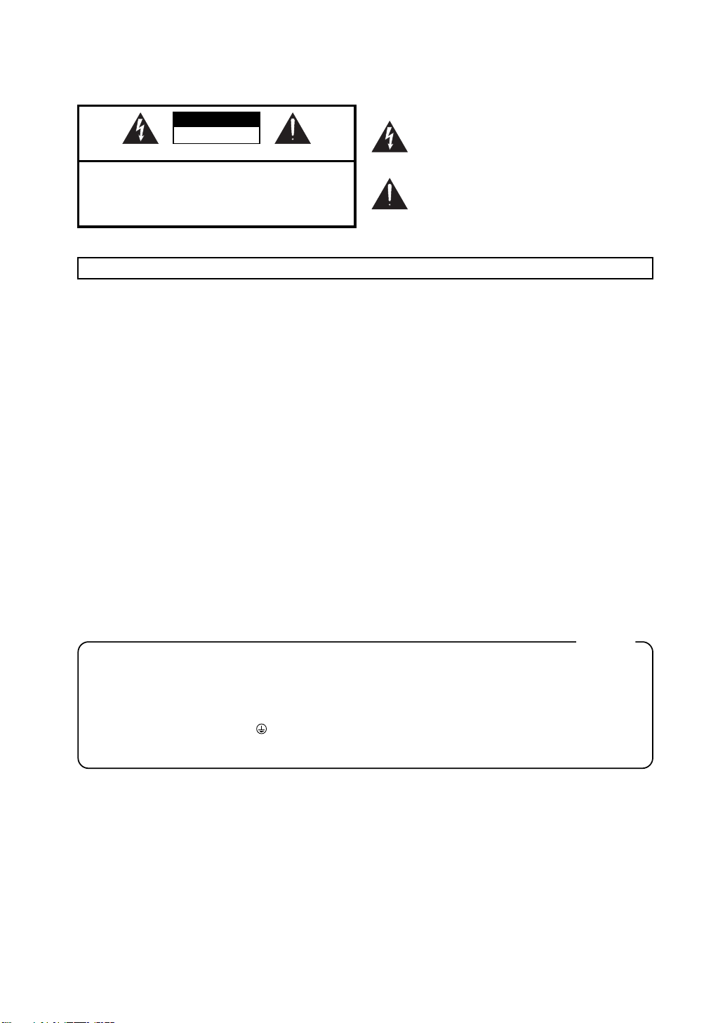
The lightning flash with arrowhead symbol, within an
equilateral triangle, is intended to alert the user to the
presence of uninsulated “dangerous voltage” within the
product’s enclosure that may be of sufficient magnitude to
constitute a risk of electric shock to persons.
The exclamation point within an equilateral triangle is
intended to alert the user to the presence of important
operating and maintenance (servicing) instructions in the
literature accompanying the product.
INSTRUCTIONS PERTAINING TO A RISK OF FIRE, ELECTRIC SHOCK, OR INJURY TO PERSONS.
IMPORTANT SAFETY INSTRUCTIONS
SAVE THESE INSTRUCTIONS
WARNING - When using electric products, basic precautions should always be followed, including the following:
1. Read these instructions.
2. Keep these instructions.
3. Heed all warnings.
4. Follow all instructions.
5. Do not use this apparatus near water.
6. Clean only with a dry cloth.
7. Do not block any of the ventilation openings. Install in
accordance with the manufacturers instructions.
8. Do not install near any heat sources such as radiators,
heat registers, stoves, or other apparatus (including
amplifiers) that produce heat.
9. Do not defeat the safety purpose of the polarized or
grounding-type plug. A polarized plug has two blades with
one wider than the other. A grounding type plug has two
blades and a third grounding prong. The wide blade or the
third prong are provided for your safety. If the provided plug
does not fit into your outlet, consult an electrician for
replacement of the obsolete outlet.
10. Protect the power cord from being walked on or pinched
particularly at plugs, convenience receptacles, and the
point where they exit from the apparatus.
11. Only use attachments/accessories specified
by the manufacturer.
12. Unplug this apparatus during lightning storms or when
unused for long periods of time.
13. Refer all servicing to qualified service personnel. Servicing
is required when the apparatus has been damaged in any
way, such as power-supply cord or plug is damaged, liquid
has been spilled or objects have fallen into the apparatus,
the apparatus has been exposed to rain or moisture, does
not operate normally, or has been dropped.
For the U.K.
WARNING:
IMPORTANT:
As the colours of the wires in the mains lead of this apparatus may not correspond with the coloured markings identifying
the terminals in your plug, proceed as follows:
The wire which is coloured GREEN-AND-YELLOW must be connected to the terminal in the plug which is marked by the
letter E or by the safety earth symbol or coloured GREEN or GREEN-AND-YELLOW.
The wire which is coloured BLUE must be connected to the terminal which is marked with the letter N or coloured BLACK.
The wire which is coloured BROWN must be connected to the terminal which is marked with the letter L or coloured RED.
Before using this unit, carefully read the sections entitled: “IMPORTANT SAFETY INSTRUCTIONS” (p. 2), “USING THE UNIT SAFELY” (p. 3), and “IMPORTANT
NOTES” (p. 6). These sections provide important information concerning the proper operation of the unit. Additionally, in order to feel assured that you have
gained a good grasp of every feature provided by your new unit, VS-700 Owner’s Manual should be read in its entirety. The manual should be saved and kept
on hand as a convenient reference.
Copyright © 2009 ROLAND CORPORATION
All rights reserved. No part of this publication may be reproduced in any form without the written permission of ROLAND CORPORATION.
THIS APPARATUS MUST BE EARTHED
THE WIRES IN THIS MAINS LEAD ARE COLOURED IN ACCORDANCE WITH THE FOLLOWING CODE.
GREEN-AND-YELLOW: EARTH, BLUE: NEUTRAL, BROWN: LIVE
Page 3
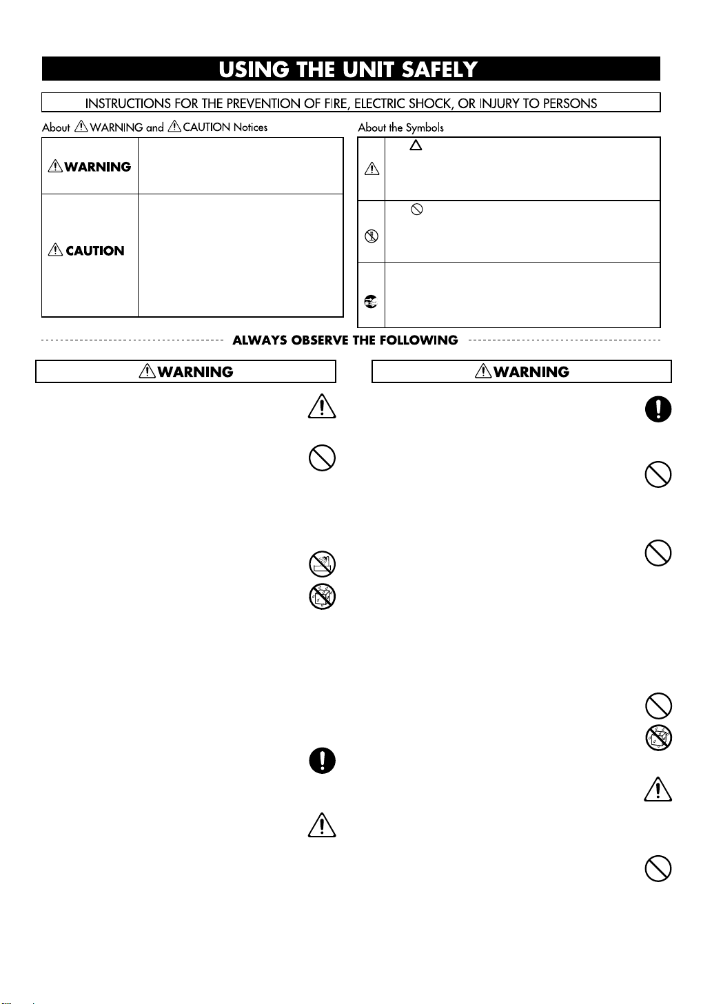
USING THE UNIT SAFELY
Used for instructions intended to alert
the user to the risk of death or severe
injury should the unit be used
improperly.
Used for instructions intended to alert
the user to the risk of injury or material
damage should the unit be used
improperly.
* Material damage refers to damage or
other adverse effects caused with
respect to the home and all its
furnishings, as well to domestic
animals or pets.
001-50
• Connect mains plug of this model to a mains socket
outlet with a protective earthing connection.
......................................................................................................................
003
• Do not attempt to repair the unit, or replace parts
within it (except when this manual provides specific
instructions directing you to do so). Refer all servicing
to your retailer, the nearest Roland Service Center, or
an authorized Roland distributor, as listed on the
“Information” (separate leaflet).
......................................................................................................................
004
• Never install the unit in any of the following locations.
• Subject to temperature extremes (e.g., direct
sunlight in an enclosed vehicle, near a heating
duct, on top of heat-generating equipment); or are
• Damp (e.g., baths, washrooms, on wet floors); or are
• Exposed to steam or smoke; or are
• Subject to salt exposure; or are
• Humid; or are
• Exposed to rain; or are
• Dusty or sandy; or are
• Subject to high levels of vibration and shakiness.
......................................................................................................................
007
• Make sure you always have the unit placed so it is level
and sure to remain stable. Never place it on stands
that could wobble, or on inclined surfaces.
......................................................................................................................
008a
• The unit should be connected to a power supply only
of the type described in the operating instructions, or
as marked on the rear side of the unit.
......................................................................................................................
The symbol alerts the user to important instructions
or warnings.The specific meaning of the symbol is
determined by the design contained within the
triangle. In the case of the symbol at left, it is used for
general cautions, warnings, or alerts to danger.
The symbol alerts the user to items that must never
be carried out (are forbidden). The specific thing that
must not be done is indicated by the design contained
within the circle. In the case of the symbol at left, it
means that the unit must never be disassembled.
The ● symbol alerts the user to things that must be
carried out. The specific thing that must be done is
indicated by the design contained within the circle. In
the case of the symbol at left, it means that the powercord plug must be unplugged from the outlet.
008e
• Use only the attached power-supply cord. Also, the
supplied power cord must not be used with any other
device.
......................................................................................................................
009
• Do not excessively twist or bend the power cord, nor
place heavy objects on it. Doing so can damage the
cord, producing severed elements and short circuits.
Damaged cords are fire and shock hazards!
......................................................................................................................
010
• This unit, either alone or in combination with an
amplifier and headphones or speakers, may be
capable of producing sound levels that could cause
permanent hearing loss. Do not operate for a long
period of time at a high volume level, or at a level that
is uncomfortable. If you experience any hearing loss or
ringing in the ears, you should immediately stop using
the unit, and consult an audiologist.
......................................................................................................................
011
• Do not allow any objects (e.g., flammable material,
coins, pins); or liquids of any kind (water, soft drinks,
etc.) to penetrate the unit.
......................................................................................................................
013
• In households with small children, an adult should
provide supervision until the child is capable of
following all the rules essential for the safe operation
of the unit.
......................................................................................................................
014
Protect the unit from strong impact.
•
(Do not drop it!)
......................................................................................................................
3
Page 4
USING THE UNIT SAFELY
015
•
Do not force the unit’s power-supply cord to share an
outlet with an unreasonable number of other devices.
Be especially careful when using extension cords—the
total power used by all devices you have connected to
the extension cord’s outlet must never exceed the
power rating (watts/amperes) for the extension cord.
Excessive loads can cause the insulation on the cord to
heat up and eventually melt through.
......................................................................................................................
016
•
Before using the unit in a foreign country, consult with
your retailer, the nearest Roland Service Center, or an
authorized Roland distributor, as listed on the
“Information” (separate leaflet).
......................................................................................................................
022a
•
Always turn the unit off and unplug the power cord
before attempting installation of the circuit board
(ARX series; p. 14).
......................................................................................................................
026
•
Do not put anything that contains water (e.g., flower
vases) on this unit. Also, avoid the use of insecticides,
perfumes, alcohol, nail polish, spray cans, etc., near the
unit. Swiftly wipe away any liquid that spills on the
unit using a dry, soft cloth.
......................................................................................................................
101a
•
The unit should be located so that its location or
position does not interfere with its proper ventilation.
......................................................................................................................
102b
•
Always grasp only the plug on the power-supply cord
when plugging into, or unplugging from, an outlet or
this unit.
......................................................................................................................
103a
•
At regular intervals, you should unplug the power
plug and clean it by using a dry cloth to wipe all dust
and other accumulations away from its prongs. Also,
disconnect the power plug from the power outlet
whenever the unit is to remain unused for an
extended period of time. Any accumulation of dust
between the power plug and the power outlet can
result in poor insulation and lead to fire.
......................................................................................................................
104
•
Try to prevent cords and cables from becoming
entangled. Also, all cords and cables should be placed
so they are out of the reach of children.
......................................................................................................................
106
Never climb on top of, nor place heavy objects on the
•
unit.
......................................................................................................................
107b
Never handle the power cord or its plugs with wet
•
hands when plugging into, or unplugging from, an
outlet or this unit.
......................................................................................................................
108a
Before moving the unit, disconnect the power plug
•
from the outlet, and pull out all cords from external
devices.
......................................................................................................................
109a
•
Before cleaning the unit, turn off the power and
unplug the power cord from the outlet (p. 14).
......................................................................................................................
110a
•
Whenever you suspect the possibility of lightning in
your area, pull the plug on the power cord out of the
outlet.
......................................................................................................................
115a
•
Install only the specified circuit board (ARX series).
Remove only the specified screws (p. 21).
......................................................................................................................
118a
•
Should you remove screws of the ARX expansion
board cover (p. 21) or the rackmount brackets (p. 29),
keep them in a safe place out of children's reach, so
there is no chance of them being swallowed
accidentally.
......................................................................................................................
4
Page 5
120
•
Always turn the phantom power off when connecting
any device other than condenser microphones that
require phantom power. You risk causing damage if
you mistakenly supply phantom power to dynamic
microphones, audio playback devices, or other
devices that don’t require such power. Be sure to
check the specifications of any microphone you
intend to use by referring to the manual that came
with it.
(This instrument’s phantom power: 48 V DC, 10mA Max)
......................................................................................................................
USING THE UNIT SAFELY
5
Page 6

IMPORTANT NOTES
Power Supply
301
• Do not connect this unit to the same electrical outlet that is
being used by an electrical appliance that is controlled by an
inverter (such as a refrigerator, washing machine, microwave
oven, or air conditioner), or that contains a motor. Depending
on the way in which the electrical appliance is used, power
supply noise may cause this unit to malfunction or may
produce audible noise. If it is not practical to use a separate
electrical outlet, connect a power supply noise filter between
this unit and the electrical outlet.
307
• Before connecting this unit to other devices, turn off the
power to all units. This will help prevent malfunctions and/or
damage to speakers or other devices.
308
• Although the LCD and LEDs are switched off when the POWER
switch is switched off, this does not mean that the unit has
been completely disconnected from the source of power. If
you need to turn off the power completely, first turn off the
POWER switch, then unplug the power cord from the power
outlet. For this reason, the outlet into which you choose to
connect the power cord’s plug should be one that is within
easy reach and readily accessible.
Placement
351
• Using the unit near power amplifiers (or other equipment
containing large power transformers) may induce hum. To
alleviate the problem, change the orientation of this unit; or
move it farther away from the source of interference.
352a
• This device may interfere with radio and television reception.
Do not use this device in the vicinity of such receivers.
352b
• Noise may be produced if wireless communications devices,
such as cell phones, are operated in the vicinity of this unit.
Such noise could occur when receiving or initiating a call, or
while conversing. Should you experience such problems, you
should relocate such wireless devices so they are at a greater
distance from this unit, or switch them off.
354a
• Do not expose the unit to direct sunlight, place it near devices
that radiate heat, leave it inside an enclosed vehicle, or
otherwise subject it to temperature extremes. Excessive heat
can deform or discolor the unit.
355b
• When moved from one location to another where the
temperature and/or humidity is very different, water droplets
(condensation) may form inside the unit. Damage or
malfunction may result if you attempt to use the unit in this
condition. Therefore, before using the unit, you must allow it
to stand for several hours, until the condensation has
completely evaporated.
360
• Depending on the material and temperature of the surface on
which you place the unit, its rubber feet may discolor or mar
the surface.
You can place a piece of felt or cloth under the rubber feet to
prevent this from happening. If you do so, please make sure
that the unit will not slip or move accidentally.
Maintenance
401a
• For everyday cleaning, wipe the unit with a soft, dry cloth or
one that has been slightly dampened with water. To remove
stubborn dirt, use a cloth impregnated with a mild, nonabrasive detergent. Afterwards, be sure to wipe the unit
thoroughly with a soft, dry cloth.
402
• Never use benzine, thinners, alcohol or solvents of any kind, to
avoid the possibility of discoloration and/or deformation.
Additional Precautions
553
• Use a reasonable amount of care when using the unit’s
buttons, sliders, or other controls; and when using its jacks
and connectors. Rough handling can lead to malfunctions.
554
• Never strike or apply strong pressure to the display.
555
• A small amount of noise may be heard from the display during
normal operation.
556
• When connecting / disconnecting all cables, grasp the
connector itself—never pull on the cable. This way you will
avoid causing shorts, or damage to the cable’s internal
elements.
557
• A small amount of heat will radiate from the unit during
normal operation.
558a
• To avoid disturbing your neighbors, try to keep the unit’s
volume at reasonable levels. You may prefer to use
headphones, so you do not need to be concerned about those
around you (especially when it is late at night).
559a
• When you need to transport the unit, package it in the box
(including padding) that it came in, if possible. Otherwise, you
will need to use equivalent packaging materials.
562
• Some connection cables contain resistors. Do not use cables
that incorporate resistors for connecting to this unit. The use
of such cables can cause the sound level to be extremely low,
or impossible to hear. For information on cable specifications,
contact the manufacturer of the cable.
Copyright
851
• Recording, duplication, distribution, sale, lease, performance,
or broadcast of copyrighted material (musical works, visual
works, broadcasts, live performances, etc.) belonging to a
third party in part or in whole without the permission of the
copyright owner is forbidden by law.
852a
• This product can be used to record or duplicate audio or visual
material without being limited by certain technological copyprotection measures. This is due to the fact that this product is
intended to be used for the purpose of producing original
music or video material, and is therefore designed so that
material that does not infringe copyrights belonging to others
(for example, your own original works) can be recorded or
duplicated freely.
6
Page 7

853
• Do not use this unit for purposes that could infringe on a
copyright held by a third party. We assume no responsibility
whatsoever with regard to any infringements of third-party
copyrights arising through your use of this unit.
IMPORTANT NOTES
204
* Microsoft and Windows and Windows Vista are registered
trademarks of Microsoft Corporation.
206j
* Windows® is known officially as: “Microsoft® Windows®
operating system.”
ADD
* MMP (Moore Microprocessor Portfolio) refers to a patent
portfolio concerned with microprocessor architecture, which
was developed by Technology Properties Limited (TPL).
Roland has licensed this technology from the TPL Group.
220
* All product names mentioned in this document are
trademarks or registered trademarks of their respective
owners.
962a
* In the interest of product improvement, the specifications
and/or appearance of this unit are subject to change without
prior notice.
7
Page 8

Contents
USING THE UNIT SAFELY............................................................................................................3
IMPORTANT NOTES .....................................................................................................................6
Checking the Contents of the Package................................................................................9
Using the VS-700R I/O in Standalone Mode.................................................................... 11
Connecting Two VS-700R I/O Units .................................................................................... 12
Connecting the Power Cord.................................................................................................. 14
Turning the Power On ............................................................................................................. 15
Connecting Recording Equipment..................................................................................... 16
Switching the Sampling Rate................................................................................................ 18
Audio Clock Source................................................................................................................... 20
Installing the ARX Expansion Board ................................................................................... 21
Installation de la carte d’expansion.................................................................................... 25
Attaching the Rackmount Brackets .................................................................................... 29
8
Page 9
Checking the Contents of the Package
As soon as you open the package, check that you have all of the included items.
If anything is missing, contact your dealer.
* This package does not include the following items that are listed in “Checking the Contents of the
Package” (p. 6) of “VS-700 Getting Started.”
• VS-700C Console
• SONAR User’s Guide
• SONAR 8 DVD-ROM
• Beatscape DVD-ROM
• Dimension Pro DVD-ROM
• SONAR 8 additional content DVD-ROM
• Power Cord (one)
• Dedicated Connection Cable
VS-700R I/O Unit
fig.pane-vs700r.eps
VS-700R Owner’s Manual
This is the manual you’re reading.
It explains how to add a VS-700R I/O unit to your system, and cautions regarding its use.
Keep this manual at hand for reference.
VS-700 Getting Started
This explains how to get set up when using the VS-700C console (sold separately) together with the VS-700R I/O unit
(this product). It also explains points to be aware of when installing the VS-700 series, and information you should
know when using the system.
VS-700 Owner’s Manual
This explains how to use the VS-700, as well as points of caution that you should remember. Keep this manual at
hand for reference.
SONAR V-STUDIO 700 CD-ROM
This contains the VS-700R I/O unit driver and editor software.
Power Cord
The power cord is for the VS-700R I/O unit.
VS-700R Rackmount Brackets (two)
You can use this hardware to install the VS-700R I/O unit in a 19” rack.
9
Page 10

Checking the Contents of the Package
USB Cable
Use this cable to connect the VS-700R I/O unit to your computer’s USB connector.
* Please use the included USB cable.
10
Page 11

Using the VS-700R I/O in Standalone Mode
To use the VS-700R I/O without connecting it to the VS-700C console, it needs to be set to “Standalone mode.”
While in Standalone mode, AUX IN cannot be used.
Changes to the Settings
In order to use the VS-700R I/O in “Standalone mode,” you need to open the top cover (ARX slot), then set the
SETTING dip switches to the positions shown below. Next, switch the unit's power off, then turn it back on again.
Normal setting Settings for Standalone mode
11
Page 12

Connecting Two VS-700R I/O Units
The Advantages of Connecting VS-700R I/O Units
By connecting two VS-700R I/O units, you'll be able to take advantage of the audio input/output of the two units,
have access to two synthesizers (Fantom VS), and be able to use two ARX expansion boards.
You will need a faster system if you connect two VS-700R I/O units.
Only ASIO is supported when using the audio input/output of the second unit
• Applications that do not support ASIO cannot be used
• The audio ports of the second unit cannot be selected if SONAR is set to the WDM/KS or MME driver
mode.
Changes to the Settings
If you use a second I/O unit, open the top cover (ARX slot) of the second unit and set its SETTING DIP switches as
fig.dsw2.eps
follows. Then turn the VS-700R’s power off, then on again.
Normal setting Setting for the second VS-700R unit
Connections
921
1.
2.
The audio/MIDI device names for the second I/O unit will be the same as for the first unit but with a “2”
added to the port name.
* To prevent malfunction and/or damage to speakers or other devices, always turn down the volume, and turn off the
power on all devices before making any connections.
Set the Sampling Rate of the two VS-700R I/O units to the same value (p. 18).
Connect the second VS-700R I/O unit to your computer’s USB connector.
12
Page 13

Connecting Two VS-700R I/O Units
Connect the WORDCLOCK.
3.
Use a BNC cable to connect the WORDCLOCK OUT connector of the first unit to the WORDCLOCK IN connector of the
second unit.
Set the audio clock source of the second unit to “Wordclock” (p. 20).
Now the audio clock of the second unit will be synchronized.
* A BNC cable is not included with this package.
4.
Start up SONAR.
The USB connectors to which you connect the two VS-700R I/O units must share the same USB controller within
your computer.
Otherwise, the audio ports of the second unit won't be recognized. If the audio ports of the second VS-700R I/O
unit are not displayed in SONAR, try reconnecting the USB cables of the two VS-700R I/O units to different
connectors on your computer, then quit and restart SONAR. Repeat this procedure until the audio ports of both
VS-700R I/O units are displayed.
Alternatively, you can connect the two VS-700R I/O units to a USB hub that is compatible with USB 2.0, and
connect the hub to your computer.
Regarding Monitoring
By connecting the direct monitor mixer output of the second VS-700R I/O unit to the first VS-700R I/O
unit, all inputs of the second I/O unit can be monitored from the first VS-700R I/O unit.
Example connections for monitoring
1. Connect the second unit’s SUB OUT to the first unit’s INPUT 7/8.
2. As the second unit’s direct monitor mixer output, select SUB.
3. On the first unit, adjust the INPUT 7/8 input level.
You’ll hear the second unit’s direct monitor signal in the first unit’s direct monitor mixer output.
13
Page 14

Connecting the Power Cord
fig.VS-700-connect04-e.eps
• Connect the power cord.
Power Cord
VS-700C Rear Panel
to Power Outlet
Power Cord
VS-700R Rear Panel
to Power Outlet
14
Page 15

Turning the Power On
941
Once the connections have been completed, turn on power to your various devices in the order specified. By
turning on devices in the wrong order, you risk causing malfunction and/or damage to speakers and other
devices.
945
If you need to turn off the power completely, first turn off the POWER switch, then unplug the power cord from
the power outlet. Refer to
Minimize the VS-700C’s [AUDIO OUTPUT]
1.
knobs (three locations).
2.
Start up your computer.
“Power Supply”
(p. 6).
VS-700C Top Panel
VS-700C Rear Panel
VS-700R Front Panel
942
3.
Turn on the power switch of the VS-700C.
4.
Turn on the power switch of two VS-700R.
Turn on the power switch of your monitor speakers.
5.
Due to a circuitry-protection feature, the VS-700R requires a few moments after power-up before it is ready
for normal operation. If the connections are correct, the VS-700R’s USB indicator will light.
If the USB indicator of the VS-700R I/O unit isn’t lit
If the USB indicator of the VS-700R isn’t lit, the driver has not been installed correctly. Refer to the
“Troubleshooting” chapter in “Getting Started.”
If the I/O indicator of the VS-700C console or the CONSOLE indicator of the VS-700R I/O unit is blinking
Check the following points.
• Are the VS-700C and VS-700R powered up?
• Are the VS-700C and VS-700R correctly connected via the dedicated cable?
• Is the VS-700 R I/O unit connected to your computer via a USB cable, and is the USB indicator of the
VS-700R I/O unit lit?
Power On
Power On
15
Page 16

Connecting Recording Equipment
Connections to the Analog Jacks
fig.VS-700-rec01-mic-e.eps
The VS-700R provides a balanced (XLR) type connector that
Connecting a Mic
VS-700R Rear Panel
The eight audio inputs (INPUT 1–8) contain phantom power supplies. From SONAR’s
“Tools” menu, open “VS-700” and select the “MIC PRE” tab, and click [+48] button to
make settings. When the system is powered up, the phantom power will be turned off.
When you load a project in SONAR, the state that is saved in the project will be reflected.
When using a condenser mic that requires a balanced (XLR) connection that
supplies phantom power, set [+48] button ON (PHANTOM ON).
When using a dynamic mic etc. that has a phone plug, set [+48] button OFF
(PHANTOM OFF).
You must leave the phantom power turned off unless you’ve connected a condenser mic that
requires a phantom power supply. Supplying phantom power to a dynamic mic or audio playback
device will cause malfunctions. For details on the specifications of your mic, refer to the owner’s
manual for your mic.
VS-700C Front Panel
For a mic,
select the “NORMAL” setting.
is wired as shown in the illustration. Check the wiring of
your device before connecting it.
Mics with
balanced (XLR) plugs
Mics with phone plugs
Use this to adjust the recording
level.
Connecting Synthesizers or Audio Equipment
VS-700R Rear Panel
If you want to connect equipment such as a synthesizer or effects processor, use
audio cables to connect the output connectors of such devices to the VS-700R’s
INPUT jacks (1, 2).
Connecting a Guitar or Bass
If you want to connect a guitar or bass directly, connect it to the
AUX IN jack located on the front panel of the VS-700C console.
For a guitar or bass,
select the “Hi-Z” setting.
When connection cables with resistors are used, the volume level of equipment connected to the inputs
(INPUT 1–8 jacks, AUX IN Jack) may be low. If this happens, use connection cables that do not contain resistors.
VS-700C Front Panel
Use this to adjust the recording
level.
Mics with phone plugs
16
Page 17

Connections to the Digital Connectors
fig.VS-700-rec02-digi-e.eps
Connecting a Digital Audio Source
If you want to digitally connect a DAT or similar device, connect its output connector (e.g., DIGITAL OUT connector) to the VS-700R's DIGITAL IN
connector.
VS-700R Rear Panel
Connecting Recording Equipment
The DIGITAL 1 coaxial connector and AES/EBU connector
are a mutually exclusive selection. To make your choice, go
to SONAR’s “Tools” menu, open “ VS-700,” selec t the “MIC
PRE” tab, and make the desired setting in the “DIGITAL 1
INPUT” field.
If you're connecting an ADAT device,
connect it to the ADAT connector.
A maximum of eight channels can be input
Using an
AES/EBU
connector
Using
a coaxial
connector
Howling could be produced depending on the location of microphones relative to speakers. This can be
remedied by:
1. Changing the orientation of the microphone(s).
2. Relocating microphone(s) at a greater distance from speakers.
3. Lowering volume levels.
17
Page 18

Switching the Sampling Rate
Use the front panel [SAMPLE RATE] knob to select the sampling rate. To make the system reflect the new setting,
you’ll need to cycle the power to the system. If you need to synchronize the VS-700 to another digital device, you
must first set this knob to the same sampling rate as the master device.
Close the software you’re using.
1.
2.
Switch off the power to the VS-700R I/O and the VS-700C console.
Set the VS-700R I/O’s [SAMPLE RATE] knob to the desired sampling rate.
3.
4.
Power up the VS-700C console.
Power up the VS-700R I/O.
5.
6.
Wait for the USB indicator to light.
7.
Switch the sampling rate in your software.
“Setting SONAR’s Sampling Rate”
The number of channels that can be used will depend on the sampling rate.
44.1/48 kHz
Input 1–8
Digital 1 In 2 2 0
Digital 2 In 8 4 0
AUX 1 1 1
Total input channels 19 15 5
Main Out 2 2 2
Sub Out 2 2 2
Output 1–10 10 10 6
Digital 1 Out 2 2 0
Digital 2 Out 8 4 0
Total output channels 24 20 10
8 8 4
(p. 19)
88.2/96 kHz 192 kHz
18
Page 19

Setting SONAR’s Sampling Rate
* In SONAR, you cannot change the sampling rate of a project that contains audio data.
1.
Start up SONAR.
2.
If an "Audio Driver Error" is displayed during startup, click [Use Anyway].
3.
Choose “Options|Audio” to display the “Audio Options” dialog box.
4.
On the “General” tab of the dialog, select a value in the Sampling Rate dropdown menu, and a
value from the Audio Driver Bit Depth dropdown menu.
5.
Click [OK] to close the “Audio Options” dialog box.
If you are asked to restart SONAR, follow the on-screen instructions. After you’ve changed the sampling rate, we
recommend that you execute “Wave Profiler...” located in the same dialog box.
6.
Restart SONAR.
The newly selected sampling rate will be in effect.
Switching the Sampling Rate
Selecting a high sampling rate will allow you to handle audio at a higher quality, but this will require a
greater level of performance from your CPU, memory, and hard disk. If you are unsure about the
performance of your computer, we recommend that you use 44,100 Hz or 48,000 Hz.
The sampling rate setting is also reflected in new project files that you subsequently create.
19
Page 20

Audio Clock Source
You can choose one of four types of clock source. The current clock source is shown by the front panel SYNC
indicator.
In the case of an external source, the indicator will light if synchronization is locked. The indicator will blink if
synchronization is not locked
If you’re using SONAR, you can select the clock source parameters as described below.
If you’re using software other than SONAR, use “VS-700R I/O Editor” which is included on the “SONAR VSTUDIO 700 CD-ROM.”
From SONAR’s “Tools” menu, open “VS-700.”
1.
Select the “MIC PRE” tab.
2.
Click the “SYNC” check box to select the clock source.
3.
If you’re adding a second VS-700R unit, set the INTERFACE field to “2.”
These settings are not stored in the VS-700.
Setting
Internal clock
Digital 1 DIGITAL 1 Synchronized to the clock of the digital audio signal being input to Digital 1.
Digital 2 (ADAT) DIGITAL 2 Synchronized to the clock of the digital audio signal being input to Digital 2.
Word clock WORDCLK
Screen label Explanation
INTERNAL The internal clock will be used as the master clock.
Synchronized to the word clock signal being input to the word clock input
connector.
20
Page 21

Installing the ARX Expansion Board
Up to one optional Expansion Board (ARX series; sold separately) can be installed in the VS-700R.
For details on ARX expansion boards, refer to the owner’s manual of your ARX expansion board.
For details on the ARX expansion editor (plug-in), refer to the online manual for the editor (plug-in).
Port settings (MIDI input and audio output)
The ARX expansion board’s ports have the following names.
Port Name
MIDI Out Port
Audio In Port ARX
Cautions When Installing an Expansion Board
• To avoid the risk of damage to internal components that can be caused by static electricity, please carefully observe
the following whenever you handle the board.
• Before you touch the board, always first grasp a metal object (such as a water pipe), so you are sure that any
static electricity you might have been carrying has been discharged.
• When handling the board, grasp it only by its edges. Avoid touching any of the electronic components or
connectors.
• Save the bag in which the board was originally shipped, and put the board back into it whenever you need to
store or transport it.
• Use a Phillips screwdriver that is suitable for the size of the screw (a number 2 screwdriver). If an unsuitable screwdriver
is used, the head of the screw may be stripped.
• To remove a screw, rotate the screwdriver counter-clockwise. To tighten the screws, rotate the screwdriver clockwise.
fig.exp01.eps
• When installing Expansion Board, remove only the specified screws.
• Be careful that the screws you remove do not drop into the interior of the VS-700R.
• Do not leave the bottom cover removed. After installation of the Expansion Board is
complete, be sure to replace the cover.
• Be careful not to cut your hand on the opening for installing the board.
• Do not touch any of the printed circuit pathways or connection terminals.
• Never use excessive force when installing a circuit board. If it doesn’t fit properly on the first attempt, remove the
board and try again.
• When circuit board installation is complete, double-check your work.
• Always turn the unit off and unplug the power cord before attempting installation of the circuit board (ARX series).
• Install only the specified circuit board (ARX series). Remove only the specified screws.
ARX
tightenloosen
21
Page 22

Installing the ARX Expansion Board
How to Install an Expansion Board
Install the Expansion Board after removing the panel cover.
1.
Before installing the Expansion Board, turn off the power of the VS-700R and all connected
devices, and disconnect all cables, including the Power cable, from the VS-700R.
From the VS-700R, remove only the screws shown in the following diagram, and detach the cover.
2.
fig.exp02.eps
VS-700R Top Panel
fig.attach01.eps
22
3.
Orient the board with the slot of the VS-700R as shown in the illustration.
Slot of the VS-700R
Latched holders
Board
(expansion board)
Roland logo
Non-latched holders
Holes that engage the
non-latched holders
Page 23

fig.attach02.eps
Installing the ARX Expansion Board
Insert the board into the VS-700R’s non-latched board holders until you hear a click.
4.
fig.attach04.eps
fig.attach06.eps
Connector
of board
Connector
of the VS-700R
5.
Gently lower the board into place.
6.
From above, press down on the board at the three locations indicated in the illustration until the
Align board’s
holes with holders
Board
Non-latched holders
latched board holders lock into place.
fig.attach07.eps
Edge of the board
where the logo
is affixed
Near the cutouts
in the board
7.
Verify that the latched board holders are locked.
Use the screws that you removed in step 2 to fasten the cover back in place.
8.
23
Page 24

Installing the ARX Expansion Board
Removing an Expansion Board
To remove an expansion board, reverse the process by which you inserted it.
1.
fig.attach08.eps
fig.attach09.eps
Unlatch the latched board holders.
Verify that the two latched board holders are unlocked, then gently pull up the board and
2.
disconnect the connector.
24
3.
Disengage the board from the non-latched board holders, and remove the board.
4.
Attach the cover by reversing step 2 of the installation process.
Page 25

Installation de la carte d’expansion
resserrerdesserrer
(French Language for Canadian Safety Standard)
Un maximum de un carte d’expansion optionnelles (serie ARX; vendues separement) peuvent etre installees dans le
VS-700R.
Precautions a prendre lors de l’installation d’une carte d’expansion
• Veuillez suivre attentivement les instructions suivantes quand vous manipulez la carte afin d’eviter tout risque
d’endommagement des pieces internes par l’electricite statique.
• Toujours toucher un objet metallique relie a la terre (comme un tuyau par exemple) avant de manipuler -la carte
pour vous decharger de l’electricite statique que vous auriez pu accumuler.
• Lorsque vous manipulez la carte, la tenir par les cotes. Evitez de toucher aux composants ou aux connecteurs.
• Conservez le sachet d’origine dans lequel etait la carte lors de l’envoi et remettez la carte dedans si vous devez la
ranger ou la transporter.
• Utilisez un tournevis de type Phillips de la taille adaptee a celle des vis (tournevis numero 2). Un tournevis inadequat
peut endommager la tete de la vis.
• Pour retirer une vis, tourner le tournevis dans le sens contraire des aiguilles d’une
montre. Pour serrer les vis, tourner le tournevis dans le sens des aiguilles d’une
montre.
• Pour installer les carte d’expansion, retirer uniquement les vis mentionnees.
• Assurez-vous que les vis retirees ne tombent pas dans le VS-700R.
• Ne pas laisser le panneau de protection avant detache. S’assurer de l’avoir rattacher apres avoir installe le disque dur.
• Faites attention de ne pas vous couper sur l’ouverture d’installation de la carte.
• Ne pas toucher aux circuits imprimes ou aux connecteurs.
• Ne jamais forcer lors de l’installation de la carte de circuits imprimes. Si la carte s’ajuste mal au premier essai, enlevez la
carte et recommencez l’installation.
• Quand l’installation de la carte de circuits imprimes est terminee, reverifiez si tout est bien installe.
• Toujours eteindre et debrancher le VS-700R avant de commencer l’installation de la carte. (ARX series).
• N'installez que les cartes de circuits imprimes spécifiées (ARX series). Enlevez seulement les vis indiquées.
25
Page 26

Installation de la carte d’expansion
Installation d’une carte d’expansion
Retirer le panneau inferieur avant d’installer les cartes d’expansion.
1.
Avant d’installer la carte d’expansion Wave, coupez l’alimentation du VS-700R et de tous les
appareils branches, et debranchez tous les cables du VS-700R, y compris le cable d’alimentation.
Sur les modeles VS-700R, retirer uniquement les vis illustrees dans le schema ci-dessous et retirer
2.
fig.exp02.eps
le couvercle.
fig.attach01f.eps
26
3.
Orienter la carte de facon a ce qu’elle s’aligne avec la vente de le VS-700R, comme le montre
l’illustration.
Fente de le VS-700R
Supports bloqués
Carte
(carte d’expansion)
Logo Roland
Supports non bloqués
Trous de retenue des
supports non bloqués
Page 27

fig.attach02f.eps
Installation de la carte d’expansion
Inserer la carte dans les supports non bloques jusqu’a ce qu’un clic se fasse entendre.
4.
fig.attach04.eps
fig.attach06f.eps
Connecteur
de la carte
Aligner les trous de la
Connecteur
de le VS-700R
5.
Abaisser la carte delicatement.
Appuyer sur la carte aux trois points indiques sur l’illustration jusqu’a ce que les supports se
6.
carte et les supports
Carte
Supports non bloqués
bloquent en place.
fig.attach07.eps
Bord de la carte
où se trouve le logo
Près des découpes
de la carte
7.
S’assurer que les supports de carte sont bien bloques.
Remettez le couvercle en place a l’aide des vis retirees a l’etape 2.
8.
27
Page 28

Installation de la carte d’expansion
Retrait d’une carte d’expansion
Pour retirer une carte d’expansion, suivre le processus inverse du processus d’insertion.
1.
Suivre les instructions donnees dans le guide d’utilisation de le VS-700R pour degager la fente ou
fig.attach08.eps
fig.attach09.eps
la carte d’expansion a ete installee.
Debloquer les supports de carte.
2.
28
3.
Verifier que les deux supports de carte sont debloques puis tirer delicatement sur la carte et
deconnecter le connecteur.
4.
Fixer le couvercle en inversant l’etape 2 du processus d’installation.
Page 29

Attaching the Rackmount Brackets
If you want to install the VS-700R I/O in a 19” rack, attach the included rackmount brackets.
1.
Disconnect all connection cables from the VS-700R, including the power cord.
As shown in the illustration below, remove three screws each from the left and right sides of the
2.
fig.rack01.eps
VS-700R.
fig.rack02.eps
3.
Attach the rackmount brackets using the screws you removed in step 2.
Install the unit in the rack as appropriate for your situation.
4.
* Fasten the screws securely.
* Be careful not to lose the included screws.
* For safety’s sake, do not use any screws other than the included ones.
* If you install the system in a 19" rack, you must leave at least 1 cm of space outside the intake vent and exhaust vent.
* Be careful when installing the unit in the rack so you do not get your fingers pinched.
For the installation, refer also to
“Placement”
(p. 6).
29
Page 30
For EU Countries
UK
DE
FR
IT
ES
PT
NL
DK
NO
SE
FI
HU
PL
CZ
SK
EE
LT
LV
SI
30
GR
Page 31

For the USA
DECLARATION OF CONFORMITY
Compliance Information Statement
Model Name :
Type of Equipment :
Responsible Party :
Address :
Telephone :
VS-700R
USB Audio Interface
Cakewalk, Inc.
268 Summer Street Boston, MA 02210 USA
(617) 423-9004
This product complies with the requirements of EMCD 2004/108/EC and LVD 2006/95/EC.
For EU Countries
For the USA
FEDERAL COMMUNICATIONS COMMISSION
RADIO FREQUENCY INTERFERENCE STATEMENT
This equipment has been tested and found to comply with the limits for a Class B digital device, pursuant to Part 15 of the
FCC Rules. These limits are designed to provide reasonable protection against harmful interference in a residential
installation. This equipment generates, uses, and can radiate radio frequency energy and, if not installed and used in
accordance with the instructions, may cause harmful interference to radio communications. However, there is no guarantee
that interference will not occur in a particular installation. If this equipment does cause harmful interference to radio or
television reception, which can be determined by turning the equipment off and on, the user is encouraged to try to correct the
interference by one or more of the following measures:
– Reorient or relocate the receiving antenna.
– Increase the separation between the equipment and receiver.
– Connect the equipment into an outlet on a circuit different from that to which the receiver is connected.
– Consult the dealer or an experienced radio/TV technician for help.
This device complies with Part 15 of the FCC Rules. Operation is subject to the following two conditions:
(1) this device may not cause harmful interference, and
(2) this device must accept any interference received, including interference that may cause undesired operation.
Unauthorized changes or modification to this system can void the users authority to operate this equipment.
This equipment requires shielded interface cables in order to meet FCC class B Limit.
For Canada
NOTICE
This Class B digital apparatus meets all requirements of the Canadian Interference-Causing Equipment Regulations.
AVIS
Cet appareil numérique de la classe B respecte toutes les exigences du Règlement sur le matériel brouilleur du Canada.
For C.A. US (Proposition 65
WARNING
This product contains chemicals known to cause cancer, birth defects and other reproductive harm, including lead.
For China
)
31
Page 32

* 5 1 0 0 0 0 2 2 4 8 - 0 2 *
 Loading...