

Page 1
Page 2
CAUTION
RISK OF ELECTRIC SHOCK
DO NOT OPEN
ATTENTION: RISQUE DE CHOC ELECTRIQUE NE PAS OUVRIR
CAUTION: TO REDUCE THE RISK OF ELECTRIC SHOCK,
DO NOT REMOVE COVER (OR BACK).
NO USER-SERVICEABLE PARTS INSIDE.
REFER SERVICING TO QUALIFIED SERVICE PERSONNEL.
The lightning flash with arrowhead symbol, within an
equilateral triangle, is intended to alert the user to the
presence of uninsulated “dangerous voltage” within the
product’s enclosure that may be of sufficient magnitude to
constitute a risk of electric shock to persons.
The exclamation point within an equilateral triangle is
intended to alert the user to the presence of important
operating and maintenance (servicing) instructions in the
literature accompanying the product.
INSTRUCTIONS PERTAINING TO A RISK OF FIRE, ELECTRIC SHOCK, OR INJURY TO PERSONS.
IMPORTANT SAFETY INSTRUCTIONS
SAVE THESE INSTRUCTIONS
WARNING - When using electric products, basic precautions should always be followed, including the following:
1. Read these instructions.
2. Keep these instructions.
3. Heed all warnings.
4. Follow all instructions.
5. Do not use this apparatus near water.
6. Clean only with a dry cloth.
7. Do not block any of the ventilation openings. Install in
accordance with the manufacturers instructions.
8. Do not install near any heat sources such as radiators,
heat registers, stoves, or other apparatus (including
amplifiers) that produce heat.
9. Do not defeat the safety purpose of the polarized or
grounding-type plug. A polarized plug has two blades with
one wider than the other. A grounding type plug has two
blades and a third grounding prong. The wide blade or the
third prong are provided for your safety. If the provided plug
does not fit into your outlet, consult an electrician for
replacement of the obsolete outlet.
10. Protect the power cord from being walked on or pinched
particularly at plugs, convenience receptacles, and the
point where they exit from the apparatus.
11. Only use attachments/accessories specified
by the manufacturer.
12. Unplug this apparatus during lightning storms or when
unused for long periods of time.
13. Refer all servicing to qualified service personnel. Servicing
is required when the apparatus has been damaged in any
way, such as power-supply cord or plug is damaged, liquid
has been spilled or objects have fallen into the apparatus,
the apparatus has been exposed to rain or moisture, does
not operate normally, or has been dropped.
WARNING:
IMPORTANT:
As the colours of the wires in the mains lead of this apparatus may not correspond with the coloured markings identifying
the terminals in your plug, proceed as follows:
The wire which is coloured GREEN-AND-YELLOW must be connected to the terminal in the plug which is marked by the
letter E or by the safety earth symbol or coloured GREEN or GREEN-AND-YELLOW.
The wire which is coloured BLUE must be connected to the terminal which is marked with the letter N or coloured BLACK.
The wire which is coloured BROWN must be connected to the terminal which is marked with the letter L or coloured RED.
THIS APPARATUS MUST BE EARTHED
THE WIRES IN THIS MAINS LEAD ARE COLOURED IN ACCORDANCE WITH THE FOLLOWING CODE.
GREEN-AND-YELLOW: EARTH, BLUE: NEUTRAL, BROWN: LIVE
For the U.K.
CAUTION: Danger of explosion if battery is incorrectly replaced.
Replace only with same or equivalent type.
WARNING: To reduce the risk of fire or electric shock, do not expose this apparatus to rain or moisture.
This product complies with the requirements of European Directive 89/336/EEC.
For EU Countries
For EU Countries
Apparatus containing
Lithium batteries
ADVARSEL!
Lithiumbatteri - Eksplosionsfare ved
fejlagtig håndtering.
Udskiftning må kun ske med batteri af
samme fabrikat og type.
Levér det brugte batteri tilbage til
leverandøren.
VARNING
Explosionsfara vid felaktigt batteribyte.
Använd samma batterityp eller en
ekvivalent typ som rekommenderas av
apparattillverkaren.
Kassera använt batteri enligt
fabrikantens instruktion.
CAUTION
Danger of explosion if battery is
incorrectly replaced.
Replace only with the same or
equivalent type recommended by the
manufacturer.
Discard used batteries according to the
manufacturer’s instructions.
ADVARSEL
Eksplosjonsfare ved feilaktig skifte av
batteri.
Benytt samme batteritype eller en
tilsvarende type anbefalt av
apparatfabrikanten.
Brukte batterier kasseres i henhold til
fabrikantens instruks joner.
VAROITUS
Paristo voi räjähtää, jos se on
virheellisesti asennettu.
Vaihda paristo ainoastaan
laitevalmistajan suosittelemaan
tyyppiin. Hävitä käytetty paristo
valmistajan ohjeiden mukaisesti.
For Canada
This Class B digital apparatus meets all requirements of the Canadian Interference-Causing Equipment Regulations.
Cet appareil numérique de la classe B respecte toutes les exigences du Règlement sur le matériel brouilleur du Canada.
NOTICE
AVIS
For the USA
FEDERAL COMMUNICATIONS COMMISSION
RADIO FREQUENCY INTERFERENCE STATEMENT
This equipment has been tested and found to comply with the limits for a Class B digital device, pursuant to Part 15 of the
FCC Rules. These limits are designed to provide reasonable protection against harmful interference in a residential
installation. This equipment generates, uses, and can radiate radio frequency energy and, if not installed and used in
accordance with the instructions, may cause harmful interference to radio communications. However, there is no guarantee
that interference will not occur in a particular installation. If this equipment does cause harmful interference to radio or
television reception, which can be determined by turning the equipment off and on, the user is encouraged to try to correct the
interference by one or more of the following measures:
– Reorient or relocate the receiving antenna.
– Increase the separation between the equipment and receiver.
– Connect the equipment into an outlet on a circuit different from that to which the receiver is connected.
– Consult the dealer or an experienced radio/TV technician for help.
This device complies with Part 15 of the FCC Rules. Operation is subject to the following two conditions:
(1) This device may not cause harmful interference, and
(2) This device must accept any interference received, including interference that may cause undesired operation.
Unauthorized changes or modification to this system can void the users authority to operate this equipment.
This equipment requires shielded interface cables in order to meet FCC class B Limit.
2 www.rolandus.com Roland VS-2480 Owner’s Manual
Page 3
USING THE UNIT SAFELY
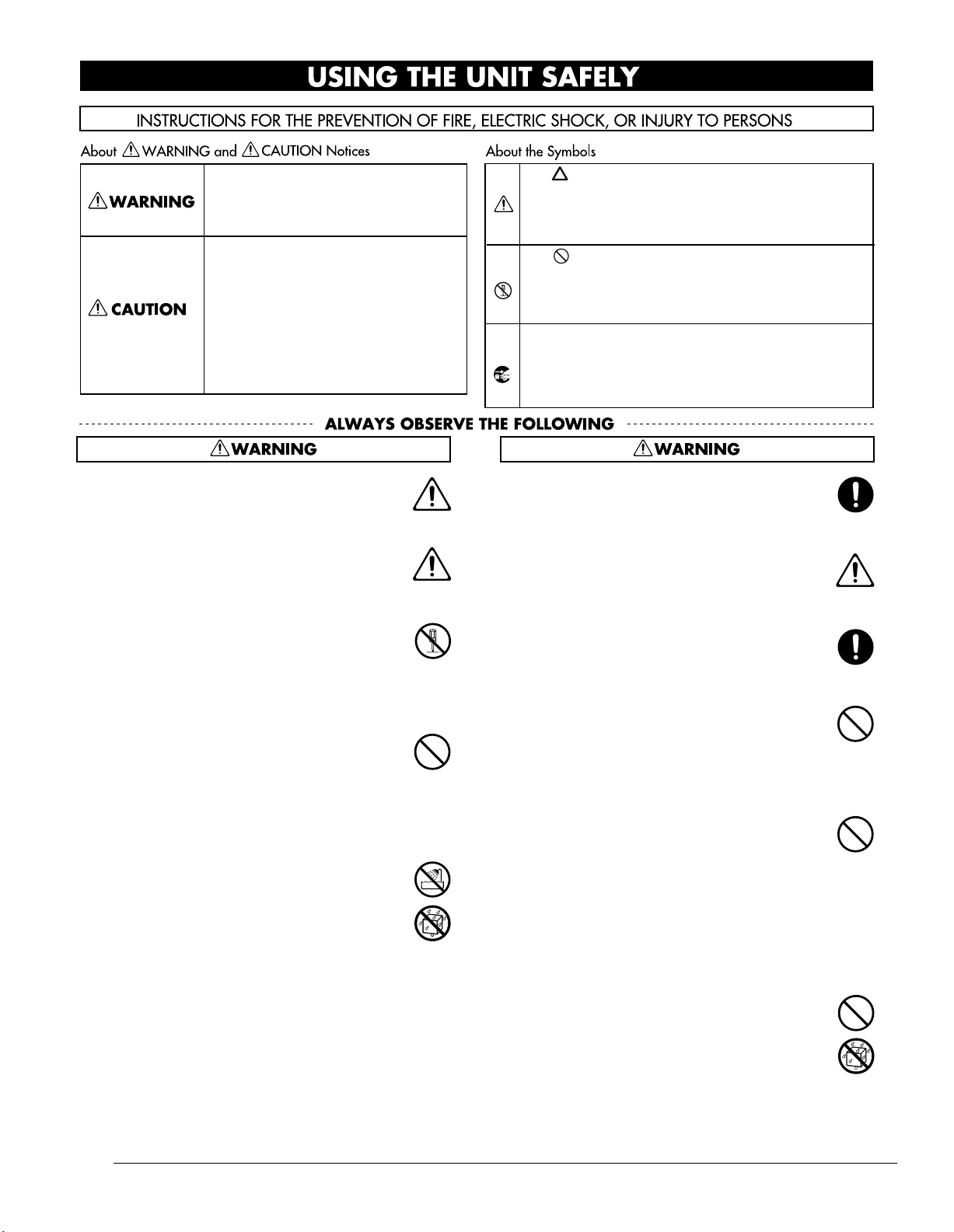
Used for instructions intended to alert
the user to the risk of death or severe
injury should the unit be used
improperly.
Used for instructions intended to alert
the user to the risk of injury or material
damage should the unit be used
improperly.
* Material damage refers to damage or
other adverse effects caused with
respect to the home and all its
furnishings, as well to domestic
animals or pets.
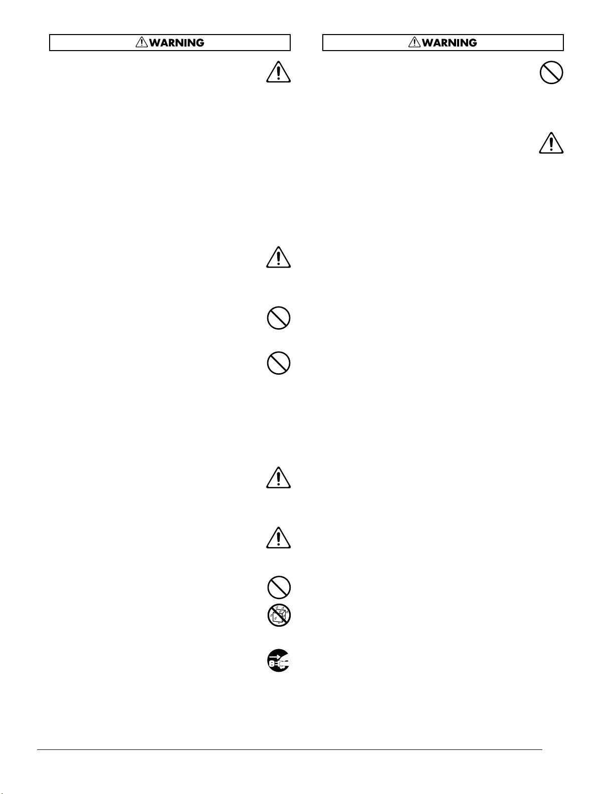
001
• Before using this unit, make sure to read the
instructions below, and the Owner’s Manual.
..........................................................................................................
001-50
• Connect mains plug of this model to a mains
socket outlet with a protective earthing
connection.
..........................................................................................................
002b
• Do not open or perform any internal modifications on the unit. (The only exception would be
where this manual provides specific instructions
which should be followed in order to put in place
user-installable options; see User Guide p. 12.)
..........................................................................................................
003
• Do not attempt to repair the unit, or replace parts
within it (except when this manual provides
specific instructions directing you to do so). Refer
all servicing to your retailer, the nearest Roland
Service Center, or an authorized Roland
distributor, as listed on the “Information” page.
..........................................................................................................
004
• Never use or store the unit in places that are:
• Subject to temperature extremes (e.g., direct
sunlight in an enclosed vehicle, near a heating
duct, on top of heat-generating equipment); or
are
• Damp (e.g., baths, washrooms, on wet floors);
or are
• Humid; or are
• Exposed to rain; or are
• Dusty; or are
• Subject to high levels of vibration.
..........................................................................................................
The symbol alerts the user to important instructions
or warnings.The specific meaning of the symbol is
determined by the design contained within the
triangle. In the case of the symbol at left, it is used for
general cautions, warnings, or alerts to danger.
The symbol alerts the user to items that must never
be carried out (are forbidden). The specific thing that
must not be done is indicated by the design contained
within the circle. In the case of the symbol at left, it
means that the unit must never be disassembled.
The symbol alerts the user to things that must be
carried out. The specific thing that must be done is
indicated by the design contained within the circle. In
the case of the symbol at left, it means that the powercord plug must be unplugged from the outlet.
007
• Make sure you always have the unit placed so it is
level and sure to remain stable. Never place it on
stands that could wobble, or on inclined surfaces.
..........................................................................................................
008a
• The unit should be connected to a power supply
only of the type described in the operating
instructions, or as marked on the rear side of unit.
..........................................................................................................
008e
• Use only the attached power-supply cord. Also,
the supplied power cord must not be used with
any other device.
..........................................................................................................
009
• Do not excessively twist or bend the power cord,
nor place heavy objects on it. Doing so can
damage the cord, producing severed elements
and short circuits. Damaged cords are fire and
shock hazards!
..........................................................................................................
010
• This unit, either alone or in combination with an
amplifier and headphones or speakers, may be
capable of producing sound levels that could
cause permanent hearing loss. Do not operate for
a long period of time at a high volume level, or at
a level that is uncomfortable. If you experience
any hearing loss or ringing in the ears, you should
immediately stop using the unit, and consult an
audiologist.
..........................................................................................................
011
• Do not allow any objects (e.g., flammable
material, coins, pins); or liquids of any kind
(water, soft drinks, etc.) to penetrate the unit.
..........................................................................................................
Roland VS-2480 Owner’s Manual www.rolandus.com 3
Page 4
012a
• Immediately turn the power off, remove the
power cord from the outlet, and request servicing
by your retailer, the nearest Roland Service
Center, or an authorized Roland distributor, as
listed on the “Information” page when:
• The power-supply cord, or the plug has been
damaged; or
• If smoke or unusual odor occurs
• Objects have fallen into, or liquid has been
spilled onto the unit; or
• The unit has been exposed to rain (or otherwise
has become wet); or
• The unit does not appear to operate normally
or exhibits a marked change in performance.
..........................................................................................................
013
• In households with small children, an adult
should provide supervision until the child is
capable of following all the rules essential for the
safe operation of the unit.
..........................................................................................................
014
• Protect the unit from strong impact.
(Do not drop it!)
..........................................................................................................
015
• Do not force the unit’s power-supply cord to
share an outlet with an unreasonable number of
other devices. Be especially careful when using
extension cords—the total power used by all
devices you have connected to the extension
cord’s outlet must never exceed the power rating
(watts/amperes) for the extension cord. Excessive
loads can cause the insulation on the cord to heat
up and eventually melt through.
..........................................................................................................
016
• Before using the unit in a foreign country, consult
with your retailer, the nearest Roland Service
Center, or an authorized Roland distributor, as
listed on the “Information” page.
..........................................................................................................
020
• Keep lithium batteries out of reach of small
children. If a child has accidentally swallowed a
battery, see a doctor immediately.
..........................................................................................................
021
• Lithium batteries must never be recharged,
heated, taken apart, or thrown into a fire or water.
023
• DO NOT play a CD-ROM disc on a conventional
audio CD player. The resulting sound may be of a
level that could cause permanent hearing loss.
Damage to speakers or other system components
may result.
..........................................................................................................
026
• Do not put anything that contains water (e.g.,
flower vases) on this unit. Also, avoid the use of
insecticides, perfumes, alcohol, nail polish, spray
cans, etc., near the unit. Swiftly wipe away any
liquid that spills on the unit using a dry, soft
cloth.
..........................................................................................................
..........................................................................................................
022a
• Always turn the unit off and unplug the power
cord before attempting installation of the circuit
board (model no. VS8F-2; p. 379).
..........................................................................................................
4 www.rolandus.com Roland VS-2480 Owner’s Manual
Page 5
101a
• The unit should be located so that its location or
position does not interfere with its proper ventilation.
..........................................................................................................
102b
• Always grasp only the plug on the power-supply
cord when plugging into, or unplugging from, an
outlet or this unit.
..........................................................................................................
103a
• At regular intervals, you should unplug the
power plug and clean it by using a dry cloth to
wipe all dust and other accumulations away from
its prongs. Also, disconnect the power plug from
the power outlet whenever the unit is to remain
unused for an extended period of time. Any
accumulation of dust between the power plug
and the power outlet can result in poor insulation
and lead to fire.
..........................................................................................................
104
• Try to prevent cords and cables from becoming
entangled. Also, all cords and cables should be
placed so they are out of the reach of children.
..........................................................................................................
106
• Never climb on top of, nor place heavy objects on
the unit.
118c
• Keep any optical connector caps or screws you
may remove and the included optical connector
caps or screws in a safe place out of children’s
reach, so there is no chance of them being
swallowed accidentally.
..........................................................................................................
120
• Always turn the phantom power off when
connecting any device other than condenser
microphones that require phantom power. You
risk causing damage if you mistakenly supply
phantom power to dynamic microphones, audio
playback devices, or other devices that don’t
require such power. Be sure to check the specifications of any microphone you intend to use by
referring to the manual that came with it.
(This instrument’s phantom power: 48 V DC,
14 mA Max)
..........................................................................................................
107b
• Never handle the power cord or its plugs with
wet hands when plugging into, or unplugging
from, an outlet or this unit.
..........................................................................................................
108a
• Before moving the unit, disconnect the power
plug from the outlet, and pull out all cords from
external devices.
..........................................................................................................
109a
• Before cleaning the unit, turn off the power and
unplug the power cord from the outlet (p. 80).
..........................................................................................................
110a
• Whenever you suspect the possibility of lightning
in your area, pull the plug on the power cord out
of the outlet.
..........................................................................................................
113
• Use only the specified type (model no. CR2032) of
lithium battery (p. 382). Be sure to insert it as
directed (to ensure correct polarity).
..........................................................................................................
114
• Used lithium batteries must be disposed of in
compliance with whatever regulations for their
safe disposal that may be observed in the region
in which you live.
..........................................................................................................
115a
• Install only the specified circuit board(s) (model
no. VS8F-2). Remove only the specified screws (p.
379).
..........................................................................................................
Roland VS-2480 Owner’s Manual www.rolandus.com 5
Page 6

Important Notes
291b
In addition to the items listed under “IMPORTANT
SAFETY INSTRUCTIONS” and “USING THE UNIT
SAFELY” on pages (p. 2) and (p. 3), please read and
observe the following:
Power Supply
301
• Do not connect this unit to same electrical outlet that is
being used by an electrical appliance that is controlled by
an inverter (such as a refrigerator, washing machine,
microwave oven, or air conditioner), or that contains a
motor. Depending on the way in which the electrical
appliance is used, power supply noise may cause this unit
to malfunction or may produce audible noise. If it is not
practical to use a separate electrical outlet, connect a
power supply noise filter between this unit and the
electrical outlet.
307
• Before connecting this unit to other devices, turn off the
power to all units. This will help prevent malfunctions
and/or damage to speakers or other devices.
308
• Although the LCD and LEDs are switched off when the
POWER switch is switched off, this does not mean that the
unit has been completely disconnected from the source of
power. If you need to turn off the power completely, first
turn off the POWER switch, then unplug the power cord
from the power outlet. For this reason, the outlet into
which you choose to connect the power cord’s plug
should be one that is within easy reach and readily accessible.
Placement
352a
• This device may interfere with radio and television
reception. Do not use this device in the vicinity of such
receivers.
352b
• Noise may be produced if wireless communications
devices, such as cell phones, are operated in the vicinity of
this unit. Such noise could occur when receiving or initiating a call, or while conversing. Should you experience
such problems, you should relocate such wireless devices
so they are at a greater distance from this unit, or switch
them off.
354a
• Do not expose the unit to direct sunlight, place it near
devices that radiate heat, leave it inside an enclosed
vehicle, or otherwise subject it to temperature extremes.
Excessive heat can deform or discolor the unit.
355b
• When moved from one location to another where the
temperature and/or humidity is very different, water
droplets (condensation) may form inside the unit. Damage
or malfunction may result if you attempt to use the unit in
this condition. Therefore, before using the unit, you must
allow it to stand for several hours, until the condensation
has completely evaporated.
Maintenance
401a
• For everyday cleaning wipe the unit with a soft, dry cloth
or one that has been slightly dampened with water. To
remove stubborn dirt, use a cloth impregnated with a
mild, non-abrasive detergent. Afterwards, be sure to wipe
the unit thoroughly with a soft, dry cloth.
402
• Never use benzine, thinners, alcohol or solvents of any
kind, to avoid the possibility of discoloration and/or
deformation.
Repairs and Data
452
• Please be aware that all data contained in the unit’s
memory may be lost when the unit is sent for repairs.
Important data should always be backed up on a storage
device (e.g., CD-R/RW disc or Zip disk), or written down
on paper (when possible). During repairs, due care is
taken to avoid the loss of data. However, in certain cases
(such as when circuitry related to memory itself is out of
order), we regret that it may not be possible to restore the
data, and Roland assumes no liability concerning such
loss of data.
Memory Backup
501b
• This unit contains a battery which powers the unit’s
memory circuits while the main power is off. When this
battery becomes weak, the message shown below will
appear in the display. Once you see this message, have the
battery replaced with a fresh one as soon as possible to
avoid the loss of all data in memory. To have the battery
replaced, consult with your retailer, the nearest Roland
Service Center, or an authorized Roland distributor, as
listed on the “Information” page.
6 www.rolandus.com Roland VS-2480 Owner’s Manual
Page 7

Important Notes
Additional Precautions
551
• Please be aware that the contents of memory can be
irretrievably lost as a result of a malfunction, or the
improper operation of the unit. To protect yourself against
the risk of loosing important data, we recommend that
you periodically save a backup copy of important data
you have stored in the unit’s memory on a storage device
(e.g., CD-R/RW disc or Zip disk).
552
• Unfortunately, it may be impossible to restore the contents
of data that was stored on a storage device (e.g.,
CD-R/RW disc or Zip disk) once it has been lost. Roland
Corporation assumes no liability concerning such loss of
data.
553
• Use a reasonable amount of care when using the unit’s
buttons, sliders, or other controls; and when using its jacks
and connectors. Rough handling can lead to malfunctions.
554
• Never strike or apply strong pressure to the display.
556
• When connecting / disconnecting all cables, grasp the
connector itself—never pull on the cable. This way you
will avoid causing shorts, or damage to the cable’s
internal elements.
557
• A small amount of heat will radiate from the unit during
normal operation.
558a
• To avoid disturbing your neighbors, try to keep the unit’s
volume at reasonable levels. You may prefer to use
headphones, so you do not need to be concerned about
those around you (especially when it is late at night).
559a
• When you need to transport the unit, package it in the box
(including padding) that it came in, if possible. Otherwise,
you will need to use equivalent packaging materials.
562
• Use a cable from Roland to make the connection. If using
some other make of connection cable, please note the
following precautions.
• Some connection cables contain resistors. Do not use
cables that incorporate resistors for connecting to this
unit. The use of such cables can cause the sound level
to be extremely low, or impossible to hear. For information on cable specifications, contact the manufacturer of the cable.
Handling Zip Disks
651
• Zip disks contain a plastic disk with a thin coating of
magnetic storage medium. Microscopic precision is
required to enable storage of large amounts of data on
such a small surface area. To preserve their integrity,
please observe the following when handling Zip disks:
• Never touch the magnetic medium inside the disk.
• Do not use or store Zip disks in dirty or dusty areas.
• Do not subject Zip disks to temperature extremes (e.g.,
direct sunlight in an enclosed vehicle). Recommended
temperature range: -22 to 51˚C (-7.6 to 123.8˚F).
• Do not expose Zip disks to strong magnetic fields, such
as those generated by loudspeakers.
653
• The identification label should be firmly affixed to the
disk. Should the label come loose while the disk is in the
drive, it may be difficult to remove the disk.
654
• Store all disks in a safe place to avoid damaging them, and
to protect them from dust, dirt, and other hazards. By
using a dirty or dust-ridden disk, you risk damaging the
disk, as well as causing the disk drive to malfunction.
Handling CD-ROMs
801
• Avoid touching or scratching the shiny underside
(encoded surface) of the disc. Damaged or dirty CD-ROM
discs may not be read properly. Keep your discs clean
using a commercially available CD cleaner.
Handling Hard Disks
Important Performance and Image
Data
811
• Once a hard disk fails to function normally, all data that
has been stored on it could be destroyed.
All hard disks eventually wear out.
you consider the hard disk not as a permanent storage
site, but as a place to store data temporarily. We also
recommend that you back up important performance and
image data that cannot be recorded again onto the
external media that is supported by your device. For
instructions on how to make such backups, refer to the
owner’s manual for your device.
Note that Roland assumes no liability whatsoever,
including monetary compensation, for the loss of any
recorded content in the event of the malfunction of, or
physical damage to the hard disk, or for any direct or
incidental damages resulting from the loss of such data.
Precautions Regarding Setup and Use
812
• Certain hard disk setup procedures and usage conditions
may result in the corruption of recorded data, malfunctioning, or physical damage to the disk, so be sure to
observe the following precautions.
• Do not subject the hard disk to vibration or shock,
especially while the unit is in operation.
• Do not set up the unit in any location where it may be
affected by vibration from external sources, or on any
surface that is not stable and level.
• If the device includes a cooling fan, ensure that the fan
and the side panel air vents remain unobstructed.
We recommend that
Roland VS-2480 Owner’s Manual www.rolandus.com 7
Page 8

Important Notes
• Do not leave the unit in any environment subject to
temperature extremes; for example, in a closed
automobile in summer or outdoors during winter.
• Do not use the unit in conditions of high temperature
and humidity or in any location subject to rapid
temperature changes.
• Do not unplug the power cord or switch off any circuit
breakers in the circuit to which the unit is connected
while the power is turned on.
• Do not move the unit while the power is turned on or
immediately after turning off the power. When transporting the unit, first turn off the power and confirm
that the display screen has gone off, disconnect the
power plug, then wait at least two minutes before
moving the device.
Emergency Procedures
813
* The following procedures are to be used as emergency
measures only, and are not recommended for normal
operation.
• If the device fails to respond to operational commands or
does not complete operations, turn off the power. If the
power does not shut off following normal shutdown
procedures, disconnect the power plug.
If the unit does not operate normally when the power is
turned on again, it may mean that the hard disk has been
damaged. In such instances, consult your dealer or the
nearest Roland Service Center. Note, however, that it may
not be possible to recover any data from the hard disk
once it has been lost.
If your device features drive check capabilities, use the
drive check function to regularly confirm that there are no
problems, even when the device is operating normally.
For more detailed information on the shutdown and drive
check procedures, refer to the Owner’s Manual.
852b
• When exchanging audio signals through a digital
connection with an external instrument, this unit can
perform recording without being subjected to some of the
restrictions of the Serial Copy Management System
(SCMS). This is because the unit is intended solely for
musical production, and is designed not to be subject to
restrictions as long as it is used to record works (such as
your own compositions) that do not infringe on the
copyrights of others. (SCMS is a feature that prohibits
second-generation and later copying through a digital
connection. It is built into MD recorders and other
consumer digital-audio equipment as a
copyright-protection feature.)
853
• Do not use this unit for purposes that could infringe on a
copyright held by a third party. We assume no responsibility whatsoever with regard to any infringements of
third-party copyrights arising through your use of this
unit.
Copyright
851
• Unauthorized recording, distribution, sale, lending, public
performance, broadcasting, or the like, in whole or in part,
of a work (musical composition, video, broadcast, public
performance, or the like) whose copyright is held by a
third party is prohibited by law.
8 www.rolandus.com Roland VS-2480 Owner’s Manual
Page 9

Table of Contents
Table of Contents
Step-by-Step Instruction Finder 20
1—Welcome 27
About this Manual .......................................................................................................................................................... 27
How the
Names ........................................................................................................................................................................ 28
Note, Tip, Glossary and Warning Icons ............................................................................................................... 28
Other Documents in the VS-2480 Box .......................................................................................................................... 29
Getting More Help .......................................................................................................................................................... 29
The Roland US Web site ......................................................................................................................................... 29
The Roland US Faxback System ............................................................................................................................ 29
Roland US Product Support ................................................................................................................................... 29
2—Getting Around 31
VS-2480 Owner’s Manual
is Organized ................................................................................................. 27
The Top Panel of the VS-2480 ........................................................................................................................................ 31
Analog Input Jacks .................................................................................................................................................. 31
Monitor/Display Controls ..................................................................................................................................... 32
Channel Strips .......................................................................................................................................................... 33
Display Area ............................................................................................................................................................. 36
TRACK EDIT Area .................................................................................................................................................. 37
EZ ROUTING, AUTOMIX, CD-RW/MASTERING and MENU Buttons ....................................................... 39
General Controls ...................................................................................................................................................... 41
SCRUB, PREVIEW and Transport Buttons .......................................................................................................... 42
LOCATOR/MARKER/SCENE Area ................................................................................................................... 44
The Rear Panel of the VS-2480 ...................................................................................................................................... 46
3—Introduction to the VS-2480 51
What’s Inside the VS-2480? ............................................................................................................................................ 51
Input Jacks and Connectors .................................................................................................................................... 51
The Mixing Console ................................................................................................................................................. 52
The Internal Effects .................................................................................................................................................. 54
The Hard Disk Recorder ......................................................................................................................................... 55
Output Jacks and Connectors ................................................................................................................................ 55
Signal Flow ....................................................................................................................................................................... 56
Projects .............................................................................................................................................................................. 56
Busses in the VS-2480 ..................................................................................................................................................... 57
What’s a Bus? ............................................................................................................................................................ 57
Achieving Perfect Levels ................................................................................................................................................ 58
What’s “Clipping?” ................................................................................................................................................. 58
How Do I Get Good Levels? .................................................................................................................................. 58
The Importance of Backing Up ..................................................................................................................................... 59
4—Setting Up and Basic Operations 61
Things You’ll Need ......................................................................................................................................................... 61
Roland VS-2480 Owner’s Manual www.rolandus.com 9
Page 10

Table of Contents
Power ......................................................................................................................................................................... 61
A Way to Listen to the VS-2480 .............................................................................................................................. 61
Getting Ready .................................................................................................................................................................. 61
Powering Up .................................................................................................................................................................... 63
What Happens During the VS-2480’s Power-Up ................................................................................................ 63
Configuring the VS-2480 ................................................................................................................................................ 64
Setting Up the VGA Monitor, Mouse and Keyboard .......................................................................................... 64
Setting the VS-2480’s Clock ..................................................................................................................................... 65
A Few Fundamental Concepts ...................................................................................................................................... 65
Selection ..................................................................................................................................................................... 65
Switches ..................................................................................................................................................................... 66
Parameters and Values ............................................................................................................................................ 66
Tools You’ll Use All the Time ........................................................................................................................................ 66
The Cursor/ZOOM Buttons ................................................................................................................................... 66
The F Buttons ............................................................................................................................................................ 66
Pages .......................................................................................................................................................................... 67
The TIME/VALUE Dial .......................................................................................................................................... 67
The ENTER/YES and EXIT/NO Buttons ............................................................................................................. 67
The SHIFT Button ..................................................................................................................................................... 68
Using a Mouse .......................................................................................................................................................... 68
Using an ASCII Keyboard ....................................................................................................................................... 69
Using the VGA Info Display ................................................................................................................................... 70
UNDO and REDO .................................................................................................................................................... 72
Naming ...................................................................................................................................................................... 73
Entering Numbers with the Numeric Keypad .................................................................................................... 74
If You’re Using DS-90A or DS-50A Monitors .............................................................................................................. 75
Setting Up for Roland’s DS-90A and DS-50A Digital Monitors ........................................................................ 75
Adjusting Your Listening Level .................................................................................................................................... 75
Playing the Factory Demos ............................................................................................................................................ 76
“What You Don’t Know” ........................................................................................................................................ 76
“Don’t Stop” .............................................................................................................................................................. 80
Turning Off the VS-2480 ................................................................................................................................................. 80
Turning Off the VS-2480 .......................................................................................................................................... 80
5—Understanding Effects 81
Harnessing the VS-2480’s Effects .................................................................................................................................. 81
Dry and Wet .............................................................................................................................................................. 81
Effect Routings ................................................................................................................................................................. 81
Insert Effects .............................................................................................................................................................. 82
Loop Effects ............................................................................................................................................................... 82
Master Effects ................................................................................................................................................................... 83
External Effects ................................................................................................................................................................ 83
Getting the Most From Your Effect Processors ........................................................................................................... 84
6—Understanding the Hard Disk Recorder 85
VS-2480 Hard Disk Drives ............................................................................................................................................. 85
What’s a Hard Drive? .............................................................................................................................................. 85
How a VS-2480 Hard Drive Organizes Data ........................................................................................................ 86
Preparing a Hard Drive for Use ............................................................................................................................. 86
Using Other V-Studio Drives ................................................................................................................................. 86
How Audio Is Recorded on a VS-2480 Hard Drive .................................................................................................... 86
How Recordings Are Played Back ................................................................................................................................ 87
10 www.rolandus.com Roland VS-2480 Owner’s Manual
Page 11

Table of Contents
Random Access ........................................................................................................................................................ 87
What’s Pointer-Based Playback? ........................................................................................................................... 87
Non-Destructive, Pointer-Based Editing ..................................................................................................................... 88
Pointer-Based Editing .............................................................................................................................................. 88
What Is a VS-2480 Track? ............................................................................................................................................... 89
The Power of V-Tracks ............................................................................................................................................ 90
Track Editing Basics ........................................................................................................................................................ 90
About Editing Phrases ............................................................................................................................................ 90
About Editing Regions ............................................................................................................................................ 91
7—Project and Drive Operations 93
Navigating the PROJECT Menu Screens ..................................................................................................................... 93
Working with the PROJECT LIST ......................................................................................................................... 93
About “Store Current?” Messages ........................................................................................................................ 94
Project Operations ........................................................................................................................................................... 95
About F6 (MARK) .................................................................................................................................................... 95
SELECT ...................................................................................................................................................................... 95
NEW ........................................................................................................................................................................... 96
NAME ........................................................................................................................................................................ 99
PROTECT .................................................................................................................................................................. 99
OPTIMIZE ............................................................................................................................................................... 100
Destination Drive Selection .................................................................................................................................. 101
COPY ....................................................................................................................................................................... 101
ERASE ...................................................................................................................................................................... 102
SPLIT ........................................................................................................................................................................ 103
COMBINE ............................................................................................................................................................... 104
BACKUP ................................................................................................................................................................. 105
RECOVER ............................................................................................................................................................... 107
IMPORT .................................................................................................................................................................. 108
EXPORT ................................................................................................................................................................... 109
Drive Operations ........................................................................................................................................................... 111
Disk Maintenance .................................................................................................................................................. 111
Fragmentation ........................................................................................................................................................ 112
Format Drive .......................................................................................................................................................... 113
Clear Partition ........................................................................................................................................................ 115
Drive Check ............................................................................................................................................................ 116
8—The Home Screen 119
Elements of the Home Screen ...................................................................................................................................... 119
Display Pop-Up Menu Button ............................................................................................................................. 119
Current Channel Display ...................................................................................................................................... 120
PAN/AUX SEND 1-8 Knob Display .................................................................................................................. 120
Meters Display ....................................................................................................................................................... 120
Position Bar ............................................................................................................................................................. 122
The Playlist ............................................................................................................................................................. 122
Meter Switches ....................................................................................................................................................... 124
Input Peak Indicators ............................................................................................................................................ 125
Current Time Location Display ........................................................................................................................... 126
Clock, Calendar ...................................................................................................................................................... 126
Using the Fader/Pan Display ..................................................................................................................................... 127
The F/P Switches ................................................................................................................................................... 127
About The ID Buttons .................................................................................................................................................. 127
Roland VS-2480 Owner’s Manual www.rolandus.com 11
Page 12

Table of Contents
9—Working with Input Signals 129
Analog Input Signals .................................................................................................................................................... 129
Making Analog Connections ................................................................................................................................ 129
Phantom Power ............................................................................................................................................................. 130
Setting Analog Input Levels ................................................................................................................................. 130
Digital Input Signals ..................................................................................................................................................... 131
Digital Connections ................................................................................................................................................ 131
Selecting the Desired Digital Inputs .................................................................................................................... 131
Digital Considerations ........................................................................................................................................... 132
The Master Clock .................................................................................................................................................... 132
Recording S/P DIF-Format Digital Input Signals ............................................................................................. 134
Routing Input Signals to Input Channels .................................................................................................................. 135
Choosing an Input Patching Screen .................................................................................................................... 135
How Input Connections Work ............................................................................................................................. 136
Patching Input Connections ................................................................................................................................. 136
10—Using the Digital Mixer 137
Changing Channels ....................................................................................................................................................... 137
Switching Between Input, Track, Aux and FX Channels ................................................................................. 137
Channel Selection .......................................................................................................................................................... 138
Selecting a Channel for Editing ............................................................................................................................ 138
About the Channel Faders ........................................................................................................................................... 138
Setting a Fader to Unity Gain and Centering its Panning ................................................................................ 138
Using the PAN/AUX SEND 1-8 Knobs ..................................................................................................................... 139
Adjusting Stereo Positioning ................................................................................................................................ 139
Setting Dynamics and EQ Parameters for One Channel .................................................................................. 139
The KNOB/FDR ASSIGN•AUX SEND 1-8 Button ................................................................................................. 140
To Set What the KNOB/FADER ASSIGN Feature Controls ........................................................................... 140
To Turn the KNOB/FADER ASSIGN Feature On and Off .............................................................................. 141
Activating Knob or Fader Control of Aux Send Levels .................................................................................... 141
Controlling a Parameter of Your Choice ............................................................................................................ 141
The MASTER Fader ...................................................................................................................................................... 142
Muting and Soloing Channel Signals ......................................................................................................................... 142
Mute Mode .............................................................................................................................................................. 143
Solo Mode ................................................................................................................................................................ 143
Scenes .............................................................................................................................................................................. 144
Basic Scene Operations .......................................................................................................................................... 144
Editing Scenes ......................................................................................................................................................... 145
Scenes in Safe Mode ............................................................................................................................................... 146
Resetting Mixer Parameters ......................................................................................................................................... 147
11—Input and Track Channel Tools 149
Viewing a CH EDIT Screen .......................................................................................................................................... 149
Introduction to the CH EDIT Screens ......................................................................................................................... 149
How the CH EDIT Screens Are Organized ........................................................................................................ 149
The CH EDIT Screens ................................................................................................................................................... 150
The CH EDIT VIEW Screen .................................................................................................................................. 150
The DYN Screen ..................................................................................................................................................... 157
The EQ Screen ......................................................................................................................................................... 162
The FX Ins Screen ................................................................................................................................................... 166
The Surrnd Screen .................................................................................................................................................. 166
The CH EDIT P.BAY Screen ................................................................................................................................. 166
12 www.rolandus.com Roland VS-2480 Owner’s Manual
Page 13

Table of Contents
The CH EDIT ASSIGN Screen ............................................................................................................................. 167
Parameter View ...................................................................................................................................................... 167
Assorted CH EDIT Tools ............................................................................................................................................. 169
The CH EDIT VIEW CpyPRM Button ................................................................................................................ 169
The DYN and EQ Screen RESET Buttons ........................................................................................................... 169
12—Working with Input Channels 171
Introduction to Input Channel Routing ............................................................................................................. 171
Routing Linked Stereo Input Channels .............................................................................................................. 171
Routing an Input Channel Signal to a Track ............................................................................................................. 172
Quick-Routing Input Channels to Tracks .......................................................................................................... 172
Input Signal Routing on the EZ ROUTING VIEW Screen ............................................................................... 174
Input Channel Signals and the Main Mix .................................................................................................................. 175
Removing Input Channel Signals from the Main Mix ..................................................................................... 175
Adding an Input Channel’s Signal to the Main Mix ........................................................................................ 175
Routing an Input Channel Signal to a Direct Bus .................................................................................................... 175
13—Operating the Hard Disk Recorder 177
The Transport Buttons .................................................................................................................................................. 177
The Main Transport Buttons ................................................................................................................................ 177
Special Transport Buttons ..................................................................................................................................... 177
The SHUTTLE Ring ............................................................................................................................................... 178
The TRACK STATUS Buttons ..................................................................................................................................... 178
How the TRACK STATUS Buttons Work .......................................................................................................... 178
Recording ....................................................................................................................................................................... 179
Before Recording a Track ...................................................................................................................................... 179
Recording a New Track ........................................................................................................................................ 179
Playback ......................................................................................................................................................................... 180
Basic Playback Procedure ..................................................................................................................................... 180
Moving Through a Project .................................................................................................................................... 180
Using Jump ............................................................................................................................................................. 180
Looped Playback .................................................................................................................................................... 181
Vari Pitch Playback ................................................................................................................................................ 182
Preview .................................................................................................................................................................... 183
Scrub ........................................................................................................................................................................ 184
Locators .......................................................................................................................................................................... 185
Basic Locator Operations ...................................................................................................................................... 186
Other Locator Operations ..................................................................................................................................... 186
Switching Automatically to Locator Mode ........................................................................................................ 187
Locators in Safe Mode ........................................................................................................................................... 187
Markers ........................................................................................................................................................................... 188
Placing a Marker .................................................................................................................................................... 189
Moving the Timeline to a Marker ........................................................................................................................ 189
Clearing Markers ................................................................................................................................................... 190
Editing Markers ..................................................................................................................................................... 190
Punching ......................................................................................................................................................................... 191
Simple Monitoring ................................................................................................................................................. 191
Before You Punch .................................................................................................................................................. 191
Punching In and Out Manually ........................................................................................................................... 192
Auto-Punching ....................................................................................................................................................... 192
Roland VS-2480 Owner’s Manual www.rolandus.com 13
Page 14

Table of Contents
14—Working with Track Channels 195
Bouncing ......................................................................................................................................................................... 195
The Mechanics of Bouncing .................................................................................................................................. 196
Mono and Stereo Bouncing ................................................................................................................................... 196
First Things First ..................................................................................................................................................... 196
Link the Destination Tracks For a Stereo Bounce .............................................................................................. 197
Routing Tracks for a Bounce ................................................................................................................................. 197
Listening as You Bounce ....................................................................................................................................... 200
Mixing the Bounce ................................................................................................................................................. 200
Performing the Bounce .......................................................................................................................................... 201
Sending a Track Channel’s Signal to a Direct Bus .................................................................................................... 202
Routing a Track to a Direct Bus ............................................................................................................................ 202
Mixing ............................................................................................................................................................................. 202
The Mechanics of Mixing ...................................................................................................................................... 202
15—The Aux and Direct Busses 205
Aux Busses ..................................................................................................................................................................... 205
Aux Bus Overview ................................................................................................................................................. 205
When Would You Use an Aux Bus? .................................................................................................................... 205
Sending a Signal to an Aux Bus ........................................................................................................................... 206
Stereo Aux Busses .................................................................................................................................................. 206
Aux Bus Levels ....................................................................................................................................................... 206
Configuring an Aux Bus ....................................................................................................................................... 207
Direct Busses .................................................................................................................................................................. 208
When Would You Use a Direct Bus? ................................................................................................................... 208
Sending a Signal to a Direct Bus .......................................................................................................................... 209
Direct Bus Levels .................................................................................................................................................... 209
Configuring a Direct Bus ....................................................................................................................................... 209
Aux Bus/Direct Bus Strategy ...................................................................................................................................... 210
Sending Signals to Internal Effects ...................................................................................................................... 210
Sending Signals to External Devices ................................................................................................................... 210
Sending Signals to Tracks ..................................................................................................................................... 210
Creating a Headphone Mix Using an Aux Bus ......................................................................................................... 211
16—Using Effects 213
Using Loop Effects ........................................................................................................................................................ 213
Setting Up an Internal Loop Effect ...................................................................................................................... 213
Setting Up an External Loop Effect ..................................................................................................................... 215
Inserting an Effect .......................................................................................................................................................... 216
About Insert Effects ................................................................................................................................................ 216
Input and Track Channel Insert Effects .............................................................................................................. 216
MASTER Bus Insert Effects ................................................................................................................................... 219
Selecting, Editing and Saving Effect Patches ............................................................................................................. 220
The EFFECT VIEW Screen .................................................................................................................................... 220
The Algorithm View Screen .................................................................................................................................. 221
Selecting Effect Patches ......................................................................................................................................... 221
Editing Effect Patches ............................................................................................................................................ 223
Saving Effect Patches ............................................................................................................................................. 224
Speaker Modeling .......................................................................................................................................................... 225
Using Speaker Modeling ....................................................................................................................................... 225
Microphone Modeling .................................................................................................................................................. 226
14 www.rolandus.com Roland VS-2480 Owner’s Manual
Page 15

Table of Contents
17—Working with FX Return Channels 227
The FX Return Channel Fader ..................................................................................................................................... 227
FX Return CH EDIT Tools ........................................................................................................................................... 227
The Main FX Return CH EDIT Screen ................................................................................................................ 228
The FX Return Parameter View Screen .............................................................................................................. 231
Routing Effects to Tracks ............................................................................................................................................. 231
Quick Routing an FX Return Channel ................................................................................................................ 232
FX Return Routing on the EZ Routing VIEW Screen ....................................................................................... 233
Adding Effects to a Headphone Mix .......................................................................................................................... 234
18—Editing Tracks 235
Editing Concepts and Overview ................................................................................................................................. 235
Phrases and Regions .............................................................................................................................................. 235
Edit Points ............................................................................................................................................................... 236
Performing Edits ........................................................................................................................................................... 237
The Appearance of Selected Tracks, Phrases and Regions .............................................................................. 237
Where Editing Takes Place ................................................................................................................................... 238
Editing Methods ..................................................................................................................................................... 239
Edit Messages ......................................................................................................................................................... 240
Editing with a Mouse ............................................................................................................................................ 241
Editing with the TRACK EDIT Buttons .............................................................................................................. 247
Editing from the TRACK Menu ........................................................................................................................... 249
19—Phrase Editing Operations 255
COPY .............................................................................................................................................................................. 255
MOVE ............................................................................................................................................................................. 257
TRIM IN .......................................................................................................................................................................... 257
TRIM OUT ...................................................................................................................................................................... 258
DELETE .......................................................................................................................................................................... 258
SPLIT ............................................................................................................................................................................... 258
NEW ................................................................................................................................................................................ 259
NORMALIZE ................................................................................................................................................................. 260
DIVIDE ........................................................................................................................................................................... 260
NAME ............................................................................................................................................................................. 261
Take Mngr ...................................................................................................................................................................... 262
20—Region Editing Operations 263
COPY .............................................................................................................................................................................. 263
MOVE ............................................................................................................................................................................. 265
INSERT ........................................................................................................................................................................... 265
CUT ................................................................................................................................................................................. 266
ERASE ............................................................................................................................................................................. 267
COMP/EXP. .................................................................................................................................................................. 267
IMPORT .......................................................................................................................................................................... 269
EXCHANGE .................................................................................................................................................................. 270
ARRANGE ..................................................................................................................................................................... 270
NAME ............................................................................................................................................................................. 272
21—Using the Phrase Pads 273
Understanding the Phrase Pads .................................................................................................................................. 274
Roland VS-2480 Owner’s Manual www.rolandus.com 15
Page 16

Table of Contents
What a Phrase Pad Plays ....................................................................................................................................... 274
Phrase Pad Setup .................................................................................................................................................... 274
Activating Phrase Pad Mode ................................................................................................................................ 275
Playing the Pads in Phrase Pad Mode ................................................................................................................ 275
Sequencing a Phrase Pad Performance ...................................................................................................................... 275
Activating Phrase Sequence Mode ...................................................................................................................... 275
The PHRASE SEQ STATUS Buttons ................................................................................................................... 275
Playing the Pads in Phrase Sequence Mode ....................................................................................................... 275
The PHRASE SEQUENCE Screens ...................................................................................................................... 276
What the Appearance of Sequenced Data Means ............................................................................................. 277
The Phrase Sequencer Grid ................................................................................................................................... 277
Phrase Sequencer Undo ......................................................................................................................................... 277
Realtime Phrase Sequencing ................................................................................................................................. 278
Step Entry ................................................................................................................................................................ 279
Phrase Pad Button Summary ................................................................................................................................ 280
Editing a Phrase Sequence ........................................................................................................................................... 281
Phrase and Region Editing of Phrase Sequenced Data ..................................................................................... 281
Phrase Sequence Editing Tools ............................................................................................................................ 281
Controlling the Sound of Sequenced Tracks ............................................................................................................. 285
Phrase Sequence Bouncing ........................................................................................................................................... 285
22—Working with the VS-2480 Outputs 287
The VS-2480 Outputs .................................................................................................................................................... 287
Output Pairs ............................................................................................................................................................ 287
Analog Output Jacks .............................................................................................................................................. 287
Digital Output Connectors ................................................................................................................................... 287
Output Signal Routing .................................................................................................................................................. 288
Bus Routing ............................................................................................................................................................. 288
Track Direct Outs ................................................................................................................................................... 289
23—EZ Routing 291
The EZ ROUTING Screens ........................................................................................................................................... 291
Navigating the EZ ROUTING Screens ................................................................................................................ 291
EZ ROUTING VIEW Screen ................................................................................................................................. 292
The EZ ROUTING PATCH BAY Screen ............................................................................................................. 292
The EZ ROUTING OUTPUT ASSIGN Screen ................................................................................................... 293
The EZ ROUTING LOOP EFFECT ASSIGN Screen ......................................................................................... 294
EZ Routing Tools ........................................................................................................................................................... 295
Saving and Loading EZ Routing Templates ............................................................................................................. 296
Saving an EZ Routing Template .......................................................................................................................... 296
Loading an EZ Routing Template ........................................................................................................................ 297
24—MIDI and Synchronization 299
MIDI Operations ............................................................................................................................................................ 299
VS-2480 MIDI Basics .............................................................................................................................................. 299
V.Fader—The VS-2480 MIDI Control Surface ................................................................................................... 300
Remote MIDI Control of the VS-2480 .................................................................................................................. 301
Remote MIDI Storage of VS-2480 Settings ......................................................................................................... 304
MIDI Metronome ................................................................................................................................................... 305
Synchronization ............................................................................................................................................................. 307
Why Sync the VS-2480? ......................................................................................................................................... 307
Basic Synchronization Concepts .......................................................................................................................... 307
16 www.rolandus.com Roland VS-2480 Owner’s Manual
Page 17

Table of Contents
Working with a Sync Track .................................................................................................................................. 311
Working with a Tempo Map ................................................................................................................................ 312
Syncing an External Device to the VS-2480 ........................................................................................................ 314
Syncing the VS-2480 to an External Device ........................................................................................................ 315
Exchanging Digital Audio Data During Synchronization ............................................................................... 317
25—Surround 319
What is Surround? ........................................................................................................................................................ 319
Surround Formats .................................................................................................................................................. 319
How the VS-2480 Delivers Surround ......................................................................................................................... 320
Turning on Surround Mode ........................................................................................................................................ 321
Positioning a Signal in the Surround Field ............................................................................................................... 322
Adjusting Master Surround Bus Levels ..................................................................................................................... 323
26—Automix 325
The Benefits of Automix .............................................................................................................................................. 325
How Automix Works ................................................................................................................................................... 325
The AUTOMIX Screen .......................................................................................................................................... 326
Activating Automix Mode .................................................................................................................................... 327
The AUTOMIX STATUS Buttons ........................................................................................................................ 327
Recording Automix Data ............................................................................................................................................. 328
Realtime Automix Recording ............................................................................................................................... 328
Realtime Punching of Automix Data .................................................................................................................. 329
Snapshot Recording of Parameter Values .......................................................................................................... 330
Playing Back Automix Data ........................................................................................................................................ 331
Editing Automix Data .................................................................................................................................................. 331
Automix Editing Concepts ................................................................................................................................... 331
Automix Editing Methods .................................................................................................................................... 333
Automix Editing Operations ................................................................................................................................ 334
Micro-Editing Automix Data ............................................................................................................................... 337
27—Mastering and CD-R/RW Operations 339
Mastering ........................................................................................................................................................................ 339
Mixing for Mastering ............................................................................................................................................ 339
Important Mastering Concepts ............................................................................................................................ 339
Working in the VS-2480 Mastering Room .......................................................................................................... 343
Editing Mastering Tracks ...................................................................................................................................... 346
Placing CD Track Markers ................................................................................................................................... 347
CD-R/RW Operations .................................................................................................................................................. 349
Creating an Audio CD .......................................................................................................................................... 349
Erasing a CD-RW Disk .......................................................................................................................................... 352
If You Encounter Error Messages During CD Burning .................................................................................... 353
The CD Player Feature .......................................................................................................................................... 353
.WAV File Importing ............................................................................................................................................. 354
Exporting Tracks and Phrases as .WAV Files .................................................................................................... 356
28—Utility Menu Parameters 359
The Main UTILITY Menu Screen ................................................................................................................................ 359
SYSTEM .......................................................................................................................................................................... 360
PHANTOM SW ...................................................................................................................................................... 360
EXT LEVEL METER (MB-24) ............................................................................................................................... 360
Roland VS-2480 Owner’s Manual www.rolandus.com 17
Page 18

Table of Contents
DRIVE ...................................................................................................................................................................... 361
VGA .......................................................................................................................................................................... 361
PS/2 MOUSE .......................................................................................................................................................... 362
PS/2 KEYBOARD .................................................................................................................................................. 362
GLOBAL ......................................................................................................................................................................... 362
OPERATION DISPLAY ........................................................................................................................................ 365
PROJECT ......................................................................................................................................................................... 366
DIGITAL I/0 ........................................................................................................................................................... 366
DISPLAY .................................................................................................................................................................. 367
PLAYREC ....................................................................................................................................................................... 367
VARI PITCH ........................................................................................................................................................... 368
SOLO/MUTE .......................................................................................................................................................... 368
PREVIEW ................................................................................................................................................................ 368
MIDI ......................................................................................................................................................................... 368
SYNC ............................................................................................................................................................................... 369
TEMPO ............................................................................................................................................................................ 369
Metronome ..................................................................................................................................................................... 369
AUTO PUNCH/LOOP ................................................................................................................................................. 371
MARKER ........................................................................................................................................................................ 371
LOCATE ......................................................................................................................................................................... 371
V.FDR .............................................................................................................................................................................. 372
SCENE ............................................................................................................................................................................. 372
AUTOMIX ...................................................................................................................................................................... 372
SURROUND ................................................................................................................................................................... 372
Oscillator/ANALYZER ................................................................................................................................................ 372
Generator ................................................................................................................................................................. 372
Analyzer .................................................................................................................................................................. 374
DATE/TIME .................................................................................................................................................................. 376
Parameter Initialization ................................................................................................................................................ 376
Resetting Mixer and UTILITY Parameters ......................................................................................................... 376
Phrase Sequencer ........................................................................................................................................................... 377
R-BUS .............................................................................................................................................................................. 377
29—Expanding the VS-2480 379
Installing a VS8F-2 Effect Expansion Board .............................................................................................................. 379
Connecting a CD-R/RW Drive to the VS-2480 ......................................................................................................... 381
Connecting a Zip Drive to the VS-2480 ...................................................................................................................... 381
Attaching an MB-24 Level Meter ................................................................................................................................ 382
Connecting the MB-24 to the VS-2480 ................................................................................................................. 382
Replacing the VS-2480’s Battery .................................................................................................................................. 382
Installing A New Internal Hard Drive ....................................................................................................................... 384
Supplemental Information 387
R-BUS Remote Control ................................................................................................................................................. 387
DIF-AT Settings ...................................................................................................................................................... 387
Using a Roland DIF-AT ......................................................................................................................................... 388
ADA-7000 Settings ................................................................................................................................................. 389
AE-7000 Settings ..................................................................................................................................................... 390
VSR-880 Settings ..................................................................................................................................................... 392
Using the VS-2480 with a VM-7000 Mixing System ................................................................................................. 393
Using a Roland VE-7000 ............................................................................................................................................... 394
Connecting the VE-7000 ........................................................................................................................................ 394
18 www.rolandus.com Roland VS-2480 Owner’s Manual
Page 19

Table of Contents
Using the VE-7000 .................................................................................................................................................. 394
Roland MB-24 Notes ..................................................................................................................................................... 396
Factory EZ Routing Templates ................................................................................................................................... 397
Recording Template .............................................................................................................................................. 397
Bouncing Template ................................................................................................................................................ 398
Mixdown Template ............................................................................................................................................... 399
Mastering Template ............................................................................................................................................... 400
Surround 2+2 Template ........................................................................................................................................ 401
Surround 3+1 Template ........................................................................................................................................ 402
Surround 3+2+1 Template .................................................................................................................................... 404
VS-2480 Tick Resolution Table .................................................................................................................................... 405
MIDI Channels and Control Change Maps .............................................................................................................. 406
V-Fader Control Messages ........................................................................................................................................... 409
Automix Parameter List ............................................................................................................................................... 410
V-Studio Song/VS-2480 Project Compatibility ........................................................................................................ 412
Recording Mode Tables ........................................................................................................................................ 412
Parameter Translations ......................................................................................................................................... 412
Glossary 415
Index 423
Roland VS-2480 Owner’s Manual www.rolandus.com 19
Page 20

Step-By-Step Instruction Finder
Step-by-Step Instruction Finder
Activating R-BUS 2, Coaxial or Optical Digital Inputs ................................................................................ 131
Activating Vari Pitch ................................................................................................................................................. 183
Attaching an MB-24 Level Meter ....................................................................................................................... 382
Auto Punch
Editing Auto Punch IN and OUT Points Manually .......................................................................................... 193
Performing an Auto Punch ................................................................................................................................... 194
Setting Auto Punch Points Using Locators ........................................................................................................ 193
Setting Auto Punch Points Using Markers ......................................................................................................... 193
Setting Auto Punch Points When a Project Isn’t Playing ................................................................................. 192
Setting Auto Punch Points While a Project Is Playing ...................................................................................... 193
Automix
AUTOMIX Button Punching ................................................................................................................................ 330
AUTOMIX STATUS BUTTON Punching ........................................................................................................... 329
Activating Automix Mode .................................................................................................................................... 327
Creating a New Automix Event ........................................................................................................................... 338
Deleting an Automix Event .................................................................................................................................. 338
Micro-Editing Automix Data ................................................................................................................................ 338
Navigating to the Automix Screen ...................................................................................................................... 326
Playing Back Automix Data .................................................................................................................................. 331
Recording a Realtime Automix ............................................................................................................................ 328
Taking a Snapshot .................................................................................................................................................. 331
Targeting Automix Data ....................................................................................................................................... 332
The AUTOMIX EDIT Screen ................................................................................................................................ 331
Undoing a Micro-Edit ............................................................................................................................................ 338
Using the AUTOMIX STATUS Buttons .............................................................................................................. 327
Aux Busses
Adjusting an Aux Bus’s Master Level ................................................................................................................. 207
Configuring an Aux Bus from a CH EDIT VIEW Screen ................................................................................. 207
Configuring an Aux Bus from a MASTER EDIT Screen .................................................................................. 207
Metering Aux Bus and Direct Bus Levels ........................................................................................................... 206
Sending a Signal to an Aux Bus ........................................................................................................................... 206
Setting Up a Headphone Mix ............................................................................................................................... 211
CD-R/RW Operations
Burning an Audio CD ............................................................................................................................................ 350
Erasing a CD-RW Disk .......................................................................................................................................... 352
Importing a .WAV File .......................................................................................................................................... 355
Making Sure You Have Enough Space ............................................................................................................... 350
Playing an Audio CD ............................................................................................................................................. 353
Changing Your Current Location in a Project ................................................................................................ 126
Channels
Activating Fader Control of Aux Send Levels ................................................................................................... 141
Assigning KNOB/FADER ASSIGN Feature to Faders .................................................................................... 140
Controlling a Parameter of Your Choice Using a Fader ................................................................................... 141
Selecting a Channel for Editing ............................................................................................................................ 138
Switching Between Input, Track, Aux and FX Channels ................................................................................. 137
20 www.rolandus.com Roland VS-2480 Owner’s Manual
Page 21

Step-By-Step Instruction Finder
To Reset a Channel’s Fader and Pan ....................................................................................................................138
Turning KNOB/FADER ASSIGN On and Off ...................................................................................................141
Connecting a CD-R/RW Drive to the VS-2480 ...............................................................................................381
Connecting a Zip Drive to the VS-2480 ...........................................................................................................381
DIF-AT
With a TASCAM DA Series Device .....................................................................................................................388
With an ADAT ........................................................................................................................................................388
Designating the Master Clock for Digital Audio Input .................................................................................133
Direct Busses
Configuring a Direct Bus .......................................................................................................................................209
External Insert-Like Effects ...................................................................................................................................208
Metering Aux Bus and Direct Bus Levels ...........................................................................................................206
Sending a Signal to a Direct Bus ...........................................................................................................................209
Drives
Clearing a Drive/Partition ....................................................................................................................................115
Formatting a Hard Drive .......................................................................................................................................114
Running Drive Check .............................................................................................................................................117
Selecting a New Destination Drive ......................................................................................................................101
Selecting an Item in the Project List .......................................................................................................................94
To Display the Projects on a Drive .........................................................................................................................94
EZ Routing
Initializing and Clearing Routings .......................................................................................................................295
Loading an EZ Routing Template ........................................................................................................................297
Making Connections on the EZ ROUTING OUTPUT ASSIGN Screen ..........................................................294
Making Connections on the EZ ROUTING PATCH BAY Screen ...................................................................293
Making Connections on the EZ ROUTING VIEW Screen ................................................................................292
Making Connections on the LOOP EFFECT ASSIGN Screen ..........................................................................294
Saving an EZ Routing Template ...........................................................................................................................296
Editing Tracks
Configuring the Behavior of the IN, OUT, FROM and TO Buttons ................................................................247
Copying Data by Dragging with Your Mouse ...................................................................................................245
Moving Data by Dragging with Your Mouse .....................................................................................................244
Moving or Copying Data Using the TRACK EDIT Buttons .............................................................................248
Performing an Edit Operation From the Edit Pop-Up Menu ...........................................................................246
Performing an Edit Operation from the TRACK Menu ....................................................................................250
Performing an Editing Operation with the TRACK EDIT Buttons .................................................................248
Placing Edit Points Using the IN, OUT, FROM and TO Buttons ....................................................................247
Placing Edit Points on a TRACK Menu Operation Screen ...............................................................................250
Placing Edit Points with Your Mouse ..................................................................................................................242
Quick-Selecting from the TRACK Menu .............................................................................................................250
Selecting Phrases By Clicking or Dragging Your Mouse ..................................................................................243
Selecting Phrases and Regions with the VS-2480’s Buttons .............................................................................247
Selecting Phrases from the SELECT PHRASE Pop-Up Menu ..........................................................................243
Selecting Regions From the SELECT TRACK Pop-Up Menu ..........................................................................244
Selecting Regions by Dragging Your Mouse ......................................................................................................243
Selecting a Track Using the VS-2480’s Buttons ...................................................................................................247
Selecting a Track with Your Mouse .....................................................................................................................242
Selection Using the TRACK Menu’s Onscreen Selection Tools .......................................................................252
Snapping to Grid .....................................................................................................................................................245
Effects
Adding Effects to a Headphone Mix ...................................................................................................................234
Roland VS-2480 Owner’s Manual www.rolandus.com 21
Page 22

Step-By-Step Instruction Finder
Editing an Effect Patch .......................................................................................................................................... 224
External Insert-Like Effects ................................................................................................................................... 208
Inserting Effects on an Input or Track Channel ................................................................................................. 217
Inserting Effects on the MASTER Bus ................................................................................................................. 219
Routing Aux and Direct Busses to Internal Effects ........................................................................................... 210
Routing Effects to Tracks ...................................................................................................................................... 231
Saving an Effect Patch ........................................................................................................................................... 225
Selecting an Effect Patch ........................................................................................................................................ 223
Setting Up an External Loop Effect ..................................................................................................................... 215
Setting Up an Internal Loop Effect ...................................................................................................................... 213
Using Microphone Modeling ............................................................................................................................... 226
Using Speaker Modeling ....................................................................................................................................... 225
Exporting .WAV Files
Burning Exported .WAV Files to CD .................................................................................................................. 358
Exporting Phrases as .WAV Files ......................................................................................................................... 357
Exporting Tracks as .WAV Files .......................................................................................................................... 356
Exporting Tracks as .WAV Files .......................................................................................................................... 356
Exporting a VS-2480 Project .............................................................................................................................. 110
Fader Groups
Assigning Channels to a Fader Group ................................................................................................................ 155
Finding Events with Microscopic Precision Using Scrub ........................................................................... 185
Headphone Mix Setup ............................................................................................................................................. 211
Importing
Recovering Backup Data ....................................................................................................................................... 107
Importing a .WAV File ............................................................................................................................................. 355
Importing a Song from an Earlier V-Studio ..................................................................................................... 108
Input Channel Signals
Removing Input Signals from the Main Mix ...................................................................................................... 175
Routing an Input Signal to Direct Bus ................................................................................................................ 175
Routing to Tracks ................................................................................................................................................... 174
Sending an Input Channel’s Signal into the Main MIX .................................................................................... 175
Installing A New Internal Hard Drive ................................................................................................................. 384
Installing a VS8F-2 Effect Expansion Board .................................................................................................. 379
KNOB/FADER ASSIGN
Activating Knob or Fader Control of Aux Send Levels .................................................................................... 141
Controlling a Parameter of Your Choice ............................................................................................................ 141
To Set What the KNOB/FADER ASSIGN Feature Controls ........................................................................... 140
To Turn the KNOB/FADER ASSIGN Feature On and Off .............................................................................. 141
Locators
Changing Locator Banks ....................................................................................................................................... 186
Clearing a Locator .................................................................................................................................................. 186
Clearing a Locator in Safe Mode .......................................................................................................................... 188
Editing Locators ..................................................................................................................................................... 186
Recalling a Locator ................................................................................................................................................. 186
Recalling a Locator in Safe Mode ......................................................................................................................... 187
Storing a Locator .................................................................................................................................................... 186
Storing a Locator in Safe Mode ............................................................................................................................ 188
Switching Automatically to Locator Mode ........................................................................................................ 187
Looping
22 www.rolandus.com Roland VS-2480 Owner’s Manual
Page 23

Step-By-Step Instruction Finder
Activating Looped Playback .................................................................................................................................182
Editing Loop FROM and TO Points Manually ...................................................................................................182
Setting Loop Points Using Locators .....................................................................................................................181
Setting Loop Points Using Markers .....................................................................................................................181
Setting Loop Points When a Project Isn’t Playing ..............................................................................................181
Setting Loop Points While a Project Is Playing ..................................................................................................181
MIDI
Changing Effect Patches via MIDI .......................................................................................................................303
Changing Scenes via MIDI ....................................................................................................................................302
Receiving SysEx Bulk Dump Data .......................................................................................................................305
Remote Control of the VS-2480 with Control Change Messages .....................................................................303
Remote Control of the VS-2480 with SysEx Messages ......................................................................................302
Sending SysEx Bulk Dump Data ..........................................................................................................................304
Setting Up a MIDI Metronome .............................................................................................................................306
Using the VS-2480 as a MIDI Control Surface ....................................................................................................301
Markers
Clearing Markers ....................................................................................................................................................190
Editing Markers ......................................................................................................................................................190
Moving the Timeline to a Marker .........................................................................................................................189
Placing a Marker .....................................................................................................................................................189
Mastering
Building Mastering Tracks Selection-by-Selection ............................................................................................344
Editing Mastering Tracks .......................................................................................................................................346
Navigating to the Mastering Room ......................................................................................................................343
Placing CD Track Markers ....................................................................................................................................348
Recording Mastering Tracks .................................................................................................................................345
Selecting the Mastering Room Operating Mode ................................................................................................343
Selecting the Mastering Tracks’ Recording Mode .............................................................................................343
Selecting the Mastering V-Tracks .........................................................................................................................344
Stretching Effects ....................................................................................................................................................346
Turning On the Mastering Room .........................................................................................................................343
Using the Mastering Tool Kit ................................................................................................................................345
Metronome
Programming the Metronome’s Beat Box ...........................................................................................................370
Sending the Metronome to Outputs ....................................................................................................................371
Setting Up a MIDI Metronome .............................................................................................................................306
Moving Through a Project ......................................................................................................................................180
Muting Channels in Mute Mode ...........................................................................................................................143
Naming
Entering a New Name Using the VS-2480 Controls ............................................................................................74
Entering a New Name from a Keyboard ...............................................................................................................74
Outputs
Routing a Pair of Busses to a Pair of Outputs .....................................................................................................288
Routing a Pair of Busses to the Stereo MONITOR Bus .....................................................................................289
Routing a Pair of Tracks to a Pair of Outputs .....................................................................................................290
Setting Up Pre or Post Track Direct Outputs ......................................................................................................290
PAN/AUX SEND 1-8 Knobs
Activating Knob Control of Any Channel Parameter .......................................................................................141
Activating Knob Control of Aux Send Levels ....................................................................................................141
Activating Knob Control of Channel Panning ...................................................................................................139
Activating Knob Control of Dynamics and EQ Parameters .............................................................................140
Roland VS-2480 Owner’s Manual www.rolandus.com 23
Page 24

Step-By-Step Instruction Finder
Assigning KNOB/FADER ASSIGN Switch to Knobs ...................................................................................... 140
Controlling a Parameter of Your Choice ............................................................................................................ 141
Turning KNOB/FADER ASSIGN On and Off .................................................................................................. 141
Phrase Pads
Activating Phrase Pad Mode ................................................................................................................................ 275
Activating Phrase Sequencer Mode ..................................................................................................................... 275
Bouncing Phrase Sequence Tracks ....................................................................................................................... 286
Controlling the Sound of Sequenced Tracks ...................................................................................................... 285
Micro-Editing Sequencer Data ............................................................................................................................. 283
Navigating to the PHRASE SEQUENCE Screens ............................................................................................. 276
Phrase Sequencing Using Step Entry with AutoLoc ......................................................................................... 279
Phrase Sequencing Using Step Entry without AutoLoc ................................................................................... 280
Phrase Sequencing in Realtime ............................................................................................................................ 278
Playing the Phrase Pads ........................................................................................................................................ 275
Quantizing Phrase Sequence Data ....................................................................................................................... 282
Setting Up a Phrase Pad ........................................................................................................................................ 274
Turning On the Phrase Sequencer Playlist Grid ................................................................................................ 277
Using Tie, Rest and BackStep ............................................................................................................................... 284
Pinpointing an Event with the PREVIEW Buttons ........................................................................................ 184
Playing Back Recorded Tracks ............................................................................................................................ 180
Playing the Factory Demos ...................................................................................................................................... 76
Power
Powering Up ............................................................................................................................................................. 63
Turning Off the VS-2480 .......................................................................................................................................... 80
Projects
Backing Up a Project .............................................................................................................................................. 106
Combining Two Projects ....................................................................................................................................... 104
Copying a Project ................................................................................................................................................... 101
Creating a New Project ............................................................................................................................................ 98
Entering a Project Comment ................................................................................................................................... 99
Erasing a Project ..................................................................................................................................................... 102
Exporting a VS-2480 Project .................................................................................................................................. 110
Importing a Song from an Earlier V-Studio ....................................................................................................... 108
Loading a Project ...................................................................................................................................................... 95
Locking and Un-Locking a Project on Your Hard Drive .................................................................................. 100
Marking a Project ..................................................................................................................................................... 95
Optimizing a Project .............................................................................................................................................. 100
Re-Naming a Project ................................................................................................................................................ 99
Recovering Backup Data ....................................................................................................................................... 107
Selecting a New Destination Drive ...................................................................................................................... 101
Selecting an Item in the Project List ....................................................................................................................... 94
Splitting a Project ................................................................................................................................................... 103
To Display the Projects on a Drive ........................................................................................................................ 94
Quick Routing
An Input Signal to a Track .................................................................................................................................... 173
Recording S/P DIF-Format Digital Input Signals ........................................................................................... 134
Recording a New Track ........................................................................................................................................... 179
Replacing the VS-2480’s Battery ...................................................................................................................... 382
Resetting Mixer and UTILITY Parameters ...................................................................................................... 376
Routing
24 www.rolandus.com Roland VS-2480 Owner’s Manual
Page 25

Step-By-Step Instruction Finder
Effects to Tracks with EZ Routing ........................................................................................................................233
Effects to Tracks with Quick Routing ..................................................................................................................232
Input Channel Signals to Tracks with EZ Routing ............................................................................................174
Input Channel Signals to Tracks with Quick Routing .......................................................................................173
Input Signals to Input Channels ...........................................................................................................................136
Tracks to Track with EZ Routing ..........................................................................................................................198
Tracks to Track with Quick Routing ....................................................................................................................197
Scenes
Changing Scene Banks ...........................................................................................................................................145
Clearing a Scene ......................................................................................................................................................145
Clearing a Scene in Safe Mode ..............................................................................................................................147
Editing Scenes ..........................................................................................................................................................145
Leaving Scene Mode ...............................................................................................................................................145
Protecting a Channel’s Settings When a Scene is Recalled ...............................................................................146
Recalling a Scene .....................................................................................................................................................145
Recalling a Scene in Safe Mode .............................................................................................................................146
Storing a Scene ........................................................................................................................................................144
Storing a Scene in Safe Mode ................................................................................................................................147
Setting Up
Roland DS-90A and DS-50A Digital Monitors .....................................................................................................75
The VS-2480’s Clock .................................................................................................................................................65
VGA Monitor, Mouse and Keyboard .....................................................................................................................64
Soloing Channels in Solo Mode ............................................................................................................................143
Spectrum Analysis Display
Analyzing Your Speakers and Room ...................................................................................................................375
Powering the Spectrum Analysis Display ..........................................................................................................374
Setting Up the Spectrum Analysis Display .........................................................................................................375
Surround
Positioning a Signal in the Surround Field .........................................................................................................322
Turning on Surround Mode ..................................................................................................................................321
Synchronization
Converting a Sync Track to a Tempo Map ..........................................................................................................314
Creating a Sync Track Automatically ..................................................................................................................311
Creating a Tempo Map from Markers .................................................................................................................314
Exchanging Digital Audio Data During Synchronization ................................................................................317
Generating a Sync Track from Markers ...............................................................................................................311
Recording a Sync Track from an External Device ..............................................................................................311
Setting Up the VS-2480 as a Sync Slave ...............................................................................................................315
Setting Up the VS-2480 as the Sync Master .........................................................................................................315
Shaping a Tempo Map By Hand ..........................................................................................................................313
Shifting the Project Start Time ..............................................................................................................................316
Starting Synchronized Playback with the VS-2480 as Master ..........................................................................315
Starting Synchronized Playback with the VS-2480 as Slave .............................................................................317
To Set an Analog Input Level ................................................................................................................................130
Track Editing
Selecting Phrases from the SELECT PHRASE Pop-Up Menu ..........................................................................243
Selecting Regions From the SELECT TRACK Pop-Up Menu ..........................................................................244
Turning Fader Control On or Off ..........................................................................................................................300
Turning Phantom Power On or Off .....................................................................................................................130
Undoing a Track Recording or Editing Operation ............................................................................................73
Roland VS-2480 Owner’s Manual www.rolandus.com 25
Page 26

Step-By-Step Instruction Finder
Using Jump ................................................................................................................................................................... 180
Using Microphone Modeling .................................................................................................................................. 226
Using Speaker Modeling ......................................................................................................................................... 225
Using a Roland VE-7000 ........................................................................................................................................ 394
Using the VS-2480 with a VM-7000 Mixing System ................................................................................ 393
Viewing a CH EDIT Screen .................................................................................................................................... 149
Zooming In and Out on the Playlist .................................................................................................................... 123
26 www.rolandus.com Roland VS-2480 Owner’s Manual
Page 27

1—Welcome
Congratulations on the purchase of your Roland VS-2480 Digital Studio Workstation.
The VS-2480 will allow you to take your music—or any other kind of sound—from the
first spark of inspiration to completed recording.
Although the VS-2480 is designed to be simple to operate, the sheer number of tools it
provides do require some introduction and explanation. That’s what the
Owner’s Manual
imagination.
If you’ve purchased a VS8F-2 Effect Board, MB-24 Meter Bridge, VS-CDRII/CD-RACK
or VE-7000 for your VS-2480—or would like to attach a Zip® drive—you may want see
Chapter 29, beginning on Page 379 before reading the
Your VS-2480 is an extremely reliable device. However, there’s no guarantee against
data loss due to improper use of the VS-2480 or unforeseen events. Roland Corporation
assumes no liability concerning such loss of data.
About this Manual
VS-2480
is for. Of course, what you do with these tools is up to you and your
Owner’s Manual
.
How the
The
and settings. It also provides application suggestions and presents step-by-step
procedures. To get the most from your VS-2480, we recommend reading the entire
manual. The structure of the manual generally reflects the order in which a typical
signal flows through the VS-2480, with extra explanations for beginners at the front.
If you’d like to get to work immediately, you may first want to:
•
•
Here’s where you’ll find some instructions that describe how to perform some basic
operations:
•
•
•
•
•
•
These procedures will get you up and running, but, of course, they’re no substitute for
actually reading the manual and really learning how the VS-2480’s features work.
VS-2480 Owner’s Manual
VS-2480 Owner’s Manual
set the VS-2480’s internal clock and calendar
recording to make it easy for you to keep track of your work. See Page 65 for
instructions.
connect a mouse, ASCII keyboard and VGA monitor
“Creating a New Project”
“Recording a New Track”
“Backing Up a Project”
“Inserting Effects on an Input or Track Channel”
“Setting Up an Internal Loop Effect”
“Mixing”
—Page 202
explains the VS-2480 ‘s architecture, features, operations
—Page 98
—Page 179
—Page 106
—Page 213
is Organized
—The VS-2480 time-stamps each
—See Page 64 for more information.
—Page 217
Roland VS-2480 Owner’s Manual www.rolandus.com 27
Page 28

1—Welcome
To make it easy for you to find the manual’s numerous step-by-step procedures, we’ve
assembled a “Step-by-Step Instruction Finder” that starts on Page 20. There’s also a
standard Table of Contents at the front of the book and an Index at the back.
Additional information can be found in the “Supplemental Information” chapter
starting on Page 387.
In this manual, illustrations that show VS-2480 screens reflect their appearance at the
time the manual was written. As the VS-2480’s software is enhanced through operating
system upgrades, the appearance of the VS-2480’s screens may change.
Names
Throughout the
well as settings that appear in the display—are shown exactly as they look on the
VS-2480 itself. As a result, names printed on the VS-2480 are shown completely in
capital letters. For example, the button labeled “PROJECT” will appear in the manual
as the PROJECT button, or simply PROJECT, as in “Press PROJECT.” Settings on the
display are shown in the same lower- and upper -case letters they use onscreen.
A few buttons serve several purposes and have long names. In such cases, we’ll refer to
the button by the name that reflects its current use. For example, if we want to view CH
EDIT parameters, we’ll say to press the “desired CH EDIT button,” not the “desired CH
EDIT/SELECT/PHRASE SEQ STATUS/AUTOMIX STATUS” button. Some buttons
have two labels. If we need to refer to both, we’ll show the labels with a bullet between
them, as with the HOME•DISPLAY button.
The F 1-6 buttons beneath the display do different things at different times. We’ll show
an F button’s current function in parentheses after its name, as in “F1 (INPUT).”
The four arrow keys are a special case. Sometimes, we’ll collectively refer
to , , and as “cursor” buttons since they allow you to move, or
“cursor,” around in the VS-2480’s display.
VS-2480 Owner’s Manual
, the names of buttons, knobs, faders, jacks—as
Note, Tip, Glossary and Warning Icons
Throughout the
hand margins. Here’s what these symbols mean.
VS-2480 Owner’s Manual
, you find the symbols shown below in the left-
Notes
provide additional information about the topic described in the main text.
Tips
offer interesting ways to use the feature under discussion. They’ll also let you know
why you should care about what’s being said.
This symbol will be of special interest to beginners, because the word—or words—to its
right can be found in the glossary that starts on Page 415.
Make sure you pay attention whenever you see the
important information that will help you avoid damage to your recordings, VS-2480,
other equipment or even yourself.
28 www.rolandus.com Roland VS-2480 Owner’s Manual
Warning
symbol. Warnings provide
Page 29

Other Documents in the VS-2480 Box
The
VS-2480 User’s Guide
you through the steps for a variety of basic operations.
The
VS-2480 Appendices
Owner’s Manual
to perform an operation that the VS-2480 doesn’t allow—the
all error messages and an explanation of what each one means. You’ll also find a
Troubleshooting section that can help you figure out what to do if the VS-2480 behaves
in an unexpected manner.
. For example, the VS-2480 will display an error message if you attempt
provides a quick look at the VS-2480’s major features. It’ll take
provide additional detailed information not included in the
Getting More Help
Appendices
1—Welcome
contain a list of
If you have questions that can’t be answered by the
offers a number of informational resources.
VS-2480 Owner’s Manual
The Roland US Web site
Visit the Roland US Web site at:
about the VS-2480 and a wealth of support materials. If you’re new to recording or
mixing, you’ll especially enjoy the downloadable booklets for beginners.
http://www.rolandus. com
. You’ll find lots of information
The Roland US Faxback System
If you can receive faxes, you can access our library of support documents 24 hours a
day, seven days a week. Call 323-890-3780 for more information about using our
faxback system.
Roland US Product Support
If you need help from a real, live person, call the Roland US Product Support team at
323-890-3740, Extension 3741.
, Roland
Roland VS-2480 Owner’s Manual www.rolandus.com 29
Page 30

1—Welcome
30 www.rolandus.com Roland VS-2480 Owner’s Manual
Page 31

2—Getting Around
VGA OUTWORD CLOCK IN SCSI
KEYBOARD SMPTE
IN
MOUSE
PS/2
PUSH
20dB
010
PHONES 2
010
PHONES 1
MONITOR
(
TIP
)
(
RING
)
(
SLEEVE
)
HOT
COLDGND
PAD
dBu
SENS
ANALOG INPUT
12345678910111213141516
12345678910111213141516
GUITAR
Hi-Z
CONTRAST
ON
-6-64-6-64-6-64-6-64-6-64-6-64-6-64-6-64-6-64-6-64-6-64-6-64-6-64-6-64-6-64-6-
64
MASTERLR AU X ALR AU X BLR
MONITOR
LR
MIDI
214365 PHONES 1 PHONES 2 SWITCH
FOOT
87
1 2
IN OUT / THRU
12345678
ANALOG MULTI OUTPUT
PATCH BAY
INPUT MIXER
ANALOG INPUT
1
1-8
2
1-8
COAXIAL
OPTICAL
CORRECT MICROPHONE CABLE
SEE OPERATION MANUAL FOR
LES MICROPHONES ET LEURS CÀBLES.
POUR BRANCHER CORRECTMENT
ATTENTION:
CAUTION:
AND MICROPHONE CONNECTION.
VOIR LE MANUEL D’UTILISATION
OPTICALCOAXIAL
1-16 L/R L/R
(
+
PHANTOM
)
+14+14+
14+14+14+14+14+14+14+14+14+14+14+14+14+14
-
44-44-44-44-44-44-44-44-44-44-44-44-44-44-44-44
1
2
5
6
3
3
4
9
8
7
The Top Panel of the VS-2480
Analog Input Jacks
The analog input jacks allow you to bring analog audio into the VS-2480’s 24-bit analogto-digital (A/D) converters using balanced XLR connectors and balanced or
unbalanced 1/4” connectors. The VS-2480 also provides -20 dB pads and level
sensitivity adjustment knobs for each input jack. We’ll explain how to correctly set an
analog input’s level in “Setting Analog Input Levels” on Page 130.
Don’t use the same-numbered XLR and TRS input jack—each pad and SENS knob
controls both jacks, so you won’t have independent control of the two jacks’ signals.
Analog, 24-bit, balanced, XLR, unbalanced, TRS, dB, pad
1—XLR Inputs 1-8
Each of the eight XLR input jacks accepts an input signal from a balanced XLR
connector.
Roland VS-2480 Owner’s Manual www.rolandus.com 31
The VS-2480 can provide phantom power for a condenser-type mic connected to an
XLR jack. See “To Turn an XLR Input Jack’s Phantom Power On or Off” on Page 130.
2—TRS Inputs 1-16
Connect a 1/4” phone-type TRS balanced or unbalanced audio connector to any of the
sixteen TRS input jacks.
Page 32

2—Getting Around
3—GUITAR HI-Z
If you’d like to plug an electric guitar or bass directly into the VS-2480, connect it to the
GUITAR HI-Z (for “high impedance”) 1/4” phone-type jack for a loud, clean signal with
a minimum of noise.
High impedance
You can use either the GUITAR HI-Z input jack or TRS Input 16, but not both at the
same time. The setting of the GUITAR HI-Z ON switch determines which of these jacks
is turned on.
4—GUITAR HI-Z ON Switch
Press the GUITAR HI-Z ON switch to turn on the GUITAR HI-Z input jack, and to turn
off TRS Input 16—when the switch is locked in its “in” position, the GUITAR HI-Z input
jack is activated.
5—PAD Switches 1-16
When the PAD button is in its “in” position, the signal in the corresponding XLR or TRS
input jack is reduced by 20 dB.
Lower the VS-2480’s MASTER fader—and Aux master faders controlling headphone
mix levels—before pressing a PAD button to avoid damage to your amp or speakers.
6—SENS Knobs 1-16
You can adjust the sensitivity of an XLR or TRS input jack by turning its SENS—for
“Sensitivity”—knob. Turn the knob all the way clockwise for a mic level (-44 dBu) device
or all the way counter-clockwise for a line level (+14 dBu) device.
When no input signal is connected or in use, turn each input jack’s SENS knob all the
way counter-clockwise—and turn on its PAD—to avoid unwanted noise.
Mic level, line level, dBu
Monitor/Display Controls
7—MONITOR Knob
This knob controls the volume of the VS-2480’s stereo MONITOR bus and outputs. It
can also set the basic listening level of the PHONES 1 and 2 jacks.
8—PHONES 1 AND PHONES 2 Knobs
These knobs control how loudly the VS-2480’s MONITOR output is heard through
headphones connected to the PHONES 1 and 2 jacks, respectively. To learn how to set
your headphone listening level, see “Adjusting Your Listening Level” on Page 75.
9—CONTRAST Knob
The CONTRAST knob allows you to change the contrast of the VS-2480’s display. Turn
the knob until the display looks its best from your viewing angle.
32 www.rolandus.com Roland VS-2480 Owner’s Manual
Page 33

Channel Strips
TRACK STATUS / PHRASE PAD
IN 1-16
SOLO
9121172183194205216227238
24
MASTER
(dB)
6
4
0
4
8
12
18
24
42
(dB)
6
4
0
4
8
12
18
24
42
TO
FROM
13 14 15 1610 11
FX 2FX 1 FX 3 FX 4 FX 5 FX 6 FX 7 FX 8
AUX 2
AUX1
MST AUX 3 AUX 4 AUX 5 AUX 6 AUX 7 AUX 8
PAN / AUX SEND 1
-
8
CH EDIT / SELECT / PHRASE SEQ STATUS / AUTOMIX STATUS
FX RTN
IN 17-24
AUX MST
TR 17-24
TR 1-16
QQ
RATIO
GAIN FREQ FREQGAIN FREQGAIN GAIN FREQTHRESHOLD ATTACK RELEASE LEVEL FREQ
EQ Low
EQ High
FADER
WRITE
READ
MANUAL
PRM
MUTE
EQ Lo -Mid EQ Hi -Mid
Dynamics
RTN
PHRASE
REC
PLAY
OFF
TRACK
PHRASE SEQ
MASTER
EDIT
V.FADER
EDIT
PHRASE
PAD P LAY
AUX
SEND
PHRASE
SEQ
PAD
/AUTOMIX
/
Filter
L
R
L
R
1
2
4
3
5
6
78
9
10
12
13
11
2—Getting Around
Each of the first sixteen channel strips contains—reading from the bottom up—a fader,
a TRACK STATUS/PHRASE PAD button, a CH EDIT/SELECT/PHRASE SEQ STATUS/
AUTOMIX STATUS button and a PAN/AUX SEND 1-8 knob. Channel strips are
described in detail in Chapters 9. At the right side of this area is the MASTER fader
(Page 142).
1—PAN/AUX SEND 1-8 Knobs
These multi-purpose knobs perform several functions, depending on the current color
of the AUX SEND•PRM EDIT button (see “7—AUX SEND•PRM EDIT Button” on
Page 34).
Each PAN/AUX SEND 1-8 knob controls its channel’s panning when the AUX
SEND•PRM EDIT button is unlit. You can set the knob to control another channel
setting if you wish. See “Using the PAN/AUX SEND 1-8 Knobs” on Page 139.
The PAN/AUX SEND 1-8 knobs are described in detail starting on Page 139.
When using the channel strips as a MIDI control surface—see Page 300—use the knobs
to transmit MIDI Control Change messages.
Channel, channel strip, fader, panning, MIDI, MIDI control surface, MIDI Control Change
messages
Roland VS-2480 Owner’s Manual www.rolandus.com 33
Page 34

2—Getting Around
2—CH EDIT/SELECT/PHRASE SEQ STATUS/AUTOMIX STATUS Buttons 1-16
When working with input, track and FX (“effect”) return channels, press this button to
view a channel’s CH EDIT settings—the button lights to show that the input, track or
FX return channel is selected. When working in Phrase Sequence or Automix modes,
the color of each of these buttons shows the current status of its sequence or Automix
track, respectively. See “3—PHRASE SEQ/AUTOMIX Key” below.
3—PHRASE SEQ/AUTOMIX Key
The PHRASE SEQ/AUTOMIX key explains the meaning of CH EDIT/PHRASE SEQ
STATUS/AUTOMIX STATUS button colors when working in Phrase Sequence or
Automix modes.
4—TRACK STATUS/PHRASE PAD Buttons 1-16, 17-24, AUX MSTR 1-8, FX RTN 1-8
When working with track channels, press this button to set each track channel’s
status—the current status of the button is shown by its color (See ““5—TRACK STATUS
Key”” below). In Phrase Pad mode, each button acts as a pad you can strike to play a
phrase. See “Playing the Pads in Phrase Pad Mode” on Page 275. These buttons are also
used when selecting destination tracks during editing.
5—TRACK STATUS Key
The TRACK STATUS key explains the meaning of TRACK STATUS/PHRASE PAD
colors so you can tell if a track channel is set to record a track, play a track, do nothing
or play a phrase.
6—Channel Strip Faders
Use each channel strip fader to make adjustments to its channel’s output level. When
using the channel strips as a MIDI control surface—see Page 300—use the faders to
transmit MIDI Control Change messages.
You can use the faders to control a variety of settings. See “To Set What the KNOB/
FADER ASSIGN Feature Controls” on Page 140.
7—AUX SEND•PRM EDIT Button
The color of the AUX SEND•PRM EDIT button shows what the PAN/AUX SEND 1-8
knobs (Page 33) are set up to do. Press the AUX SEND•PRM EDIT button to change its
setting. When the button is:
•
Unlit
—Each PAN/AUX SEND 1-8 knob controls the PAN setting of its channel.
•
Red
—Each PAN/AUX SEND 1-8 knob adjusts the value of the setting printed
beneath it for the currently selected channel.
•
Green
—Each PAN/AUX SEND 1-8 knob controls the send level from its channel to
the currently selected Aux bus. See “The KNOB/FDR ASSIGN•AUX SEND 1-8
Button” on Page 140 to learn how to set the AUX SEND•PRM EDIT button to green.
An AUX SEND•PRM EDIT button color key is printed above and below the button.
34 www.rolandus.com Roland VS-2480 Owner’s Manual
Page 35

2—Getting Around
8—PHRASE PAD PLAY•PHRASE SEQ Button
This button activates and de-activates the playing of phrases and the recording of
phrase sequences using the TRACK STATUS/PHRASE PAD buttons. When the
PHRASE PAD PLAY•PHRASE SEQ button is:
•
Unlit
—Phrase Pad and Phrase Sequence modes are turned off.
•
Green
—Phrase Pad mode is activated.
•
Red
—Phrase Sequence mode is activated.
•
Flashing red
—the phrase sequencer is recording.
9—IN 1-16•SOLO
Press the IN 1-16•SOLO button to assign the sixteen channel strips to Input Channels
1-16 (see Page 137). Hold SHIFT and press IN 1-16•SOLO to enter and exit Solo mode
(Page 143).
10—IN 17-24/AUX MST•MUTE
Press the IN 17-24/AUX MST•MUTE button to assign the first eight channel strips to
Input Channels 17-24 and the rest to the eight Aux master channels (see Page 137).
Hold SHIFT and press IN 17-24•MUTE to enter and exit Mute mode (Page 143.).
11—TR 1-16•MASTER EDIT
Press the TR 1-16•MASTER EDIT button to assign the sixteen channel strips to Track
Channels 1-16 (see Page 137). Hold down SHIFT and press TR 1-16•MASTER EDIT to
display the MASTER EDIT VIEW screen (Page 207, Page 209).
12—TR 17-24/FX RTN•V. FADER
Press the TR 17-24/FX RTN•V. FADER button to assign the first eight channel strips to
Track Channels 17-24 and the rest to the eight FX return channels (see Chapter 17).
Hold SHIFT and press TR 17-24/FX RTN•V. FADER to change the mixer into a MIDI
control surface (see Page 300).
13—MASTER FADER
The position of the MASTER fader sets the level of the main stereo MASTER mix bus.
Since the MONITOR outputs and the PHONES jacks are typically set to listen to the
MASTER mix bus, the position of the MASTER fader also affects your listening level.
Roland VS-2480 Owner’s Manual www.rolandus.com 35
Page 36

2—Getting Around
Display Area
1
PAGE
F1 F2 F3 F4 F5 F6
DISPLAY
HOME
234
The LCD display and its buttons are central to everything you do on the VS-2480. The F
buttons discussed in Chapter 4, on Page 66.
1—LCD Display
The LCD display is your window to all of the VS-2480’s operations. In addition to
providing you vital information, the display is central to every VS-2480 activity.
2—F Buttons 1-6
The F 1-6 buttons are “soft” buttons whose job changes depending on what you’re
doing. When an F button is active, its current function is shown on the display above
the button. For more on how the F buttons work, see Page 66.
3—PAGE Button
Some activities on the VS-2480 require more than a single screenful of settings—each
screenful is called a “page.” For such activities, you can repeatedly press the PAGE
button to cycle through the available pages.
4—HOME•DISPLAY Button
Press the HOME•DISPLAY button to return to the VS-2480’s Home screen, described
in detail in Chapter 8, beginning on Page 119. Hold SHIFT and press the button to
change what appears in the playlist area of the Home screen (Page 124).
Although the HOME•DISPLAY button is actually labeled as “DISPLAY•HOME,” we
call it HOME•DISPLAY to reflect its most typical use.
36 www.rolandus.com Roland VS-2480 Owner’s Manual
Page 37

2—Getting Around
ROUTING
EZ
AUTOMIX
CD
-
RW
MASTERING
PATCH BAY
REDO
UNDO
TRACK EDIT Area
1
2 3 4 5 6 7 8
EZ
ROUTING
COPY MOVE TRIM IN TRIM OUT DELETE SPLIT NEW
PATCH BAY
COPY MOVE INSERT CUT ERASE COMP / EXP.
AUTOMIX
CD
RW
MASTERING
9 10 11 12 13 14 15
You’ll use the top row of buttons in this area as shortcuts when editing the regions and
phrases of recorded tracks—the TRACK EDIT buttons are described on Page 247. To
learn about tracks, phrases and regions, see Chapter 6, starting on Page 85. To learn
about editing phrase and regions, see Chapters 18-20. You’ll also use the TRACK EDIT
buttons when working with Automix data; see Chapter 26. The buttons you’ll need
when you want to use the VS-2480’s Auto Punch feature or when you want to loop a
part of a song are also found in this area.
Tracks, regions, phrases, Automix, Auto Punch, punch, loop
TRACK EDIT
PHRASE
REGION
IMPORT
AUTOMIX
GRADATION
LOOPA.PUNCH TOOUTIN FROM
WAVE DISP
UNDO
REDO
The function of Buttons 1-7 in the illustration above depends on whether you’re editing
regions, phrases or Automix data, as shown by the color of the PHRASE•REGION
•AUTOMIX button. In the following text, the label above most of the buttons—for
phrase editing—appears before the label beneath it that applies to region and Automix
editing, which works with regions of Automix data. Two of the buttons have three
labels: one each for phrase editing, region editing and Automix operations.
1—COPY•COPY Button
Press this button to copy a currently selected phrase or region.
2—MOVE•MOVE Button
Press this button to move a currently selected phrase or region.
3—TRIM IN•INSERT Button
• When editing a phrase, press this button to change where the phrase begins.
• When editing a region, press this button to insert silence into the selected region,
pushing subsequent recorded data back in time.
4—TRIM OUT•CUT Button
• When editing a phrase, use this button to change where the phrase ends.
• When editing a region, press this button to delete the selected region, moving
subsequent recorded data forward in time.
5—DELETE•ERASE Button
• When editing a phrase, press this button to delete the phrase from the track
without affecting its other audio.
• When editing a region, press this button to clear the selected region of all data.
Roland VS-2480 Owner’s Manual www.rolandus.com 37
Page 38

2—Getting Around
6—SPLIT•COMP/EXP Button
• When editing phrases, press this button to split the selected phrase at the timeline.
• When editing regions, press this button to perform time compression or expansion
on the currently selected track region, or scaling of automated parameter values.
Timeline
7—NEW•IMPORT•GRADATION Button
• When editing phrases, press this button to create a new phrase from a recorded
take on your hard drive.
• When editing regions, press this button to copy a recording from a different project
(Page 56) into the current project.
• When using Automix, press this to view the Gradation dialog (Page 337).
8—PHRASE•REGION•AUTOMIX Button
Press this button to select the type of editing you wish to do: phrase, region or Automix
editing. The color of the button—as shown in the key to its left—shows the currently
selected type of editing:
•
Green
—phrase editing •
•
Red
—region editing
Orange
—Automix editing
9—A. PUNCH Button
Press this button to activate (lit) or de-activate (unlit) Auto Punch. See Page 192.
10—IN Button
Press the IN button to set the current position of the timeline as the start of a region of
data you want to edit, or as the punch-in location when holding down A.PUNCH.
11—OUT Button
Press the OUT button to set the current position of the timeline as the end of a region of
data you want to edit, or as the punch-out location when holding down A.PUNCH.
12—FROM Button
Press FROM to select the current position of the timeline as a time-reference point in a
section of data to be moved or copied. When looping, press FROM while holding down
LOOP when the timeline’s at the location you want to use as the start of your loop.
13—TO Button
Press TO to select the current position of the timeline as a location at which you want
the FROM point to be placed when data is moved or copied. When looping, press TO
while holding down LOOP when the timeline’s at the location you want to use as the
end of your loop.
IN, FROM, OUT and TO work together, playing a part in a variety of editing operations.
They’re discussed as a group in Chapter 18, on Page 236.
38 www.rolandus.com Roland VS-2480 Owner’s Manual
Page 39

2—Getting Around
TR
ACK EDIT
COPY
MOVE
INSERT
CUTERER
ASE
COMP / E
XP.
IMPORT
LOOP
A.PUNCH
TO
OUT
IN
FROM
WAVE DISP
REDO
UNDO
COPY
MOVE
TRIM IN
TRIM OUT
DELETETE
SPLITNENEW
REGION
PHR
ASE
AUTOMIX
ADATION
14—LOOP Button
Press this button to turn looping on (lit) or off (unlit). See Page 181.
15—WAVE DISPLAY Button
Press WAVE DISPLAY to view the currently selected track’s audio as waveform data
(lit) or as a simple rectangle (unlit).
Waveform data
EZ ROUTING, AUTOMIX, CD-RW/MASTERING and MENU Buttons
TR
TRIM OUT
CUT
FROM
7
ACK EDIT
DELE
SPLIT
ASE
COMP / E
XP.
LOOP
TO
IMPOR
GRGRADATION
WAVE DISP
PHR
REGION
AUTOMI X
UNDO
REDO
ASE
1
2
3
EZ
ROUTING
COPY
MOVE
PATCH BAY
COPY
AUTOMIX
CD-RW
MASTERING
MOVE
A.PUNCH
PROJECT TR ACK EFFECT UTILITY
456
TRIM IN
INSERT
OUT
IN
MENU
1—EZ ROUTING Button
Press the EZ ROUTING button to set up, load and save signal routings in the VS-2480:
To learn about see:
Routing input signals to input channels Chapter 9
Routing input channels to tracks Chapter 12
Recording tracks onto other tracks Chapter 14
Routing FX return channels to tracks Chapter 17
Configuring the digital inputs Chapter 9
Activating and de-activating phantom power Chapter 9
Setting up output signals Chapter 22
Sending channels to the internal effects Chapter 16
Saving and loading EZ Routing templates Chapter 23
Clearing routings Chapter 23
Initializing routings Chapter 23
Routing
2—AUTOMIX Button
Press this button to turn Automix on (lit) or off (unlit). Hold down SHIFT and press
AUTOMIX to view the Automix edit screen. See Chapter 26, starting on Page 325.
Roland VS-2480 Owner’s Manual www.rolandus.com 39
Page 40

2—Getting Around
3—CD-RW•MASTERING Button
Press this button to view the CD-RW/MASTERING menu. From there you can enter
the VS-2480’s Mastering Room—where you can complete the master mix of a project
and create an audio CD—play audio CDs on a connected Roland CD-R/RW drive or
import and export .WAV files. See Chapter 27, starting on Page 339.
Mastering, CD-R/RW drive
4—PROJECT Button
When you press PROJECT, a menu appears in which you’ll find an assortment of
project-management tools and tools for working with your internal IDE drive and a
connected Zip drive.
IDE, hard drive, removable disk drive
5—TRACK Button
Press the TRACK button to view the TRACK region and phrase editing menus.
The TRACK region and phrase editing menus work hand-in-hand with the TRACK
EDIT area buttons described beginning on Page 37.
6—EFFECT Button
Press EFFECT to set up the VS-2480’s internal effects. Chapter 5 discusses important
underlying effects concepts. Chapter 16 provides the specifics on using the VS-2480’s
internal effects.
7—UTILITY Button
The UTILITY button provides access to the UTILITY menu, which offers a wide variety
of settings that determine the behavior of the VS-2480. See Chapter 28, starting on
Page 359.
40 www.rolandus.com Roland VS-2480 Owner’s Manual
Page 41

General Controls
/ /
WAVE DISP
LOOP
SPLITNENEW
REGION
PHR
ASE
AUTOMIX
ADATION
2—Getting Around
1
MIDI DISK
/
SHIFT
SPLIT
LOOP
GRGRADATION
WAVE DISP
+
ZOOM
TIME / VALUE
SHUTTLE
PHR
AUTOMIX
+
REGION
UNDO
REDO
ASE
8
7
6
2
EXIT
ENTER
YES NO
3
4
This area contains frequently used controls that are part of many VS-2480 operations.
5
1—MIDI/DISK Indicator
The MIDI/DISK indicator lights:
•
Green
—whenever the VS-2480 receives MIDI data from an external device.
•
Red
—whenever the internal IDE drive is being read or being written to.
2—SHIFT Button
Many of the VS-2480’s buttons have a secondary function. When you hold SHIFT and
press one of these buttons, the button performs the function shown in its boxed label.
See Page 68 for more information on using the SHIFT button.
3—ENTER/YES Button
Press ENTER/YES in response to a yes/no question shown on the display, to execute a
procedure, mark an item currently selected on the display or select data for editing.
The ENTER/YES button often flashes to underscore that you’re being asked a question
on the display or that further options are available for your current activity.
4—EXIT/NO Button
Press EXIT/NO in response to a question on the display, to cancel an operation, exit the
current screen or un-mark an object currently selected on the display.
The EXIT/NO button often flashes to underscore that you’re being asked a question on
the display.
Roland VS-2480 Owner’s Manual www.rolandus.com 41
Page 42

2—Getting Around
5—TIME/VALUE Dial
The TIME/VALUE dial—located inside the SHUTTLE ring—performs two important
jobs:
• During project playback, you can turn the dial to move forward or backward in
time. See Page 126 for more information.
• Turn the TIME/VALUE dial to adjust settings.
6—SHUTTLE Ring
Turn the SHUTTLE ring—the wheel that surrounds the TIME/VALUE dial—to move
quickly back (counter-clockwise) or forward (clockwise) through a project. See “The
SHUTTLE Ring” on Page 178 for details.
7—
Press the , , or cursor buttons to move the selection cursor (Page 65) around
the VS-2480’s display.
Hold down SHIFT and press the desired arrow button to zoom in and out on track data
shown in the playlist area of the Home screen (Page 119) and other screens:
(Cursor)/ZOOM Buttons
• Press to increase the horizontal magnification.
• Press to decrease the horizontal magnification.
• Press to increase the vertical magnification.
• Press to decrease the vertical magnification.
8—UNDO•REDO Button
The VS-2480 allows you to reverse—or “undo”—up to 999 of your last recording or
editing actions. Press the UNDO•REDO button to view the Undo dialog. After undoing
any action, you can also “redo” it by pressing UNDO•REDO while holding down
SHIFT—the Redo dialog appears.
SCRUB, PREVIEW and Transport Buttons
234
PREVIEW
TO THRU
SCRUB
1
ZERO STOP PLAY REC
SHUT / EJECT
678 9
FROM
EXT SYNC
PROJECT ENDPROJECT TOP
5
AUTOMIX RECRESTARTSTORE
1—SCRUB Button
When you need to precisely locate a moment in a track, press SCRUB to activate the
Scrub feature. When SCRUB is lit, you can turn the TIME/VALUE dial to move the
timeline and listen to a tiny piece of the track play over and over—this lets you zero in
on just the moment you’re looking for. This can be very helpful when editing. To turn
off scrubbing, press SCRUB again so its light goes out. See Page 184 to learn more.
42 www.rolandus.com Roland VS-2480 Owner’s Manual
Page 43

2—Getting Around
2—PREVIEW TO•PROJECT TOP Button
Press PREVIEW TO to listen to the last few moments leading up to the current location
of the timeline—you can set how much you want to hear. Hold SHIFT and press
PREVIEW TO to jump to the start, or “top,” of the audio recorded in the project.
3—PREVIEW THRU Button
Press PREVIEW THRU to listen to a small chunk of audio leading up to the current
location of the timeline and a small chunk that plays after it, as determined by the
PREVIEW TO and PREVIEW FROM time settings.
4—PREVIEW FROM•PROJECT END Button
Press PREVIEW FROM to listen to what occurs just after the current location of the
timeline—you can set how much you want to hear. Hold SHIFT and press PREVIEW
FROM to jump to the end of the audio recorded in the project.
PREVIEW TO, PREVIEW THRU and PREVIEW FROM work together, and are all
described in detail in “Preview” on Page 183.
5—EXT SYNC Button
Press EXT SYNC so that it lights to synchronize the VS-2480’s playback to an external
MTC- or SMPTE-generating device. Press it again so that it’s not lit when you want the
VS-2480 itself to provide the master timing reference (this is the VS-2480’s normal
operating mode). Synchronization is described in Chapter 24. Hold down SHIFT and
press EXT SYNC to jump to the VS-2480’s synchronization settings.
MTC, SMPTE
6—ZERO•STORE Button
Press ZERO•STORE to return to the beginning of the project (Time 00h00m00s00f00)—
see Page 126. Hold down SHIFT and press ZERO•STORE to save the current state of
your project to your hard drive.
7—STOP•SHUT/EJECT Button
Press STOP to halt playback at the timeline’s current location—see Page 122. Hold
down SHIFT and press STOP•SHUT/EJECT to power down the VS-2480—you’ll be
asked if you want to save your project first—and to eject any mounted Zip drive
cartridges.
8—PLAY•RESTART Button
Press PLAY•RESTART to begin playback from the current location of the timeline—see
Page 122. Hold down SHIFT and press PLAY •RESTART to restart the VS-2480 instead
of turning it off after you’ve performed a shutdown procedure (SHIFT + STOP•SHUT/
EJECT).
Roland VS-2480 Owner’s Manual www.rolandus.com 43
Page 44

2—Getting Around
LOCATOR/MARKER/SCENE Area
9—REC•AUTOMIX REC Button
Hold down REC•AUTOMIX REC and press PLAY to record audio onto a track (see
Page 179). When the AUTOMIX button (Page 39) is lit, hold down REC•AUTOMIX and
press PLAY to record mixer settings as Automix data—see Chapter 26 (Page 325) to
learn about automated mixing on the VS-2480.
Realtime
LOCATOR / MARKER / SCENE
LOCATOR
1
BANK AUX 7 AUX 8 USER
MARKER
2
3
4
AUX 4 AUX 5 AUX 6
1
AUX 1 AUX 2 AUX 3
PREVIOUS NEXT
56
/-
0
987
32
11 10
SCENE
9
BANK
8
7
4
5 6
The buttons in this area are described in detail in Chapter 13, starting on Page 177,
except as noted.
1—LOCATOR•BANK Button
Press the LOCATOR•BANK button so it’s lit to store and recall locators using the
numeric keypad (see “11—Numeric keypad•AUX 1-8, USER” on Page 46). A locator
remembers a particular timeline position within a project—when you recall the locator,
the timeline instantly jumps back to that time position. Locators are discussed in detail
in “Locators” on Page 185.
Each project can contain up to 100 locators arranged in groups, or “banks,” of ten
locators each. To select a locator bank, hold down SHIFT, press LOCATOR•BANK so it’s
lit, and press the desired bank’s number on the numeric keypad.
2—MARKER Button
Press the MARKER button so it’s lit to create and recall markers using the numeric
keypad (see “11—Numeric keypad•AUX 1-8, USER” on Page 46). Each project can
contain up to 1,000 markers, numbered from 000 to 999. Markers are used for
navigation during editing, looping and punching. Special markers are used for track
indexing when creating an audio CD.
3—CLEAR Button
To delete a locator, marker or scene, hold down CLEAR and press the desired locator,
marker or scene (Page 144) number on the numeric keypad.
44 www.rolandus.com Roland VS-2480 Owner’s Manual
Page 45

2—Getting Around
4—NUMERICS Button
Press NUMERICS so that it lights to enter numeric values for various settings using the
VS-2480’s keypad or a connected ASCII keyboard. When NUMERICS is lit, the area
into which you can type becomes selected on the display. See Page 74.
5—PREVIOUS Button
Press PREVIOUS to move the timeline to the beginning of the currently selected track
phrase or to the end of the phrase immediately before it. Hold down SHIFT and press
PREVIOUS to move the timeline back in time to the nearest marker.
6—NEXT Button
Press NEXT to move the timeline to the end of the currently selected track phrase or to
the beginning of the phrase immediately after it. Hold down SHIFT and press NEXT to
move the timeline forward in time to the nearest marker.
7—JUMP Button
You can jump to any location in a project by pressing JUMP and entering the desired
time location on the VS-2480’s numeric keypad or TIME/VALUE dial. You can select the
desired time in time code (01:01:01:01.01) at the left of the dialog that appears, or
measures, beats and clocks (001-01-001) at the right. Press ENTER/YES to move to the
selected location.
8—KNOB/FDR ASSIGN•AUX SEND 1-8 Button
When you press the KNOB/FDR ASSIGN•AUX SEND 1-8 button so that it flashes, you
can press a number on the numeric keypad to assign the PAN/AUX SEND 1-8 knobs to
the job of sending signals from the individual channel strips (Page 33) to the
corresponding Aux bus. In addition, you can press 9•USER to assign them to another
setting of your choice. See Page 141.
9—TAP•SNAPSHOT Button
Press TAP•SNAPSHOT to create a marker at the current position of the timeline—the
marker is numbered automatically. When AUTOMIX (Page 325) is lit, press AUTOMIX
and this button to create a snapshot of your current mixer settings that can be recalled
as part of an automated mix. Automix and snapshots are discussed in Chapter 26. Hold
down CD-RW•MASTERING and press TAP•SNAPSHOT to place a CD track marker at
the timeline’s current location.
10—SCENE•BANK Button
Press the SCENE•BANK button so it’s lit to store and recall scenes using the numeric
keypad (see “11—Numeric keypad•AUX 1-8, USER” on Page 46). A scene stores your
current mixer settings, allowing you to save different versions of your project for
instant recall. Scenes are discussed in detail in “Scenes” on Page 144.
Each project can contain up to 100 scenes in groups, or “banks,” of ten scenes each. To
select a scene bank, hold down SHIFT, press SCENE•BANK so it’s lit, and press the
desired bank’s number on the numeric keypad.
Roland VS-2480 Owner’s Manual www.rolandus.com 45
Page 46

2—Getting Around
POWER
ON
AC IN
1
23
The Rear Panel of the VS-2480
11—Numeric keypad•AUX 1-8, USER
The numeric keypad serves two general purposes:
• You can type the desired number or numbers on it when storing and recalling
locators, scenes and markers, or when entering values when NUMERICS is lit.
• When KNOB/FDR ASSIGN•AUX SEND 1-8 is flashing, you can assign the PAN/
AUX SEND 1-8 knobs to the job of sending signals from the individual channel
strips to one of the eight Aux busses (Page 141) by pressing the desired 1-8 button,
or to some other job by pressing 9•USER (also Page 141).
Bus
Every set of ten items on the numeric keypad—banks, locators, scenes and so on—is
numbered from 0 to 9.
1—POWER Switch
Use the POWER switch to turn the VS-2480
on and off.
Don’t simply flip the POWER switch
when you want to shut down the
VS-2480—if you do this, data loss may
occur. Make sure to use the proper
shutdown procedure, described on
Page 80.
2—AC IN Jack
Connect one end of the supplied AC power
cord to a grounded AC outlet, and the other
end to the AC IN jack.
Use only the supplied AC power cord to prevent damage to your VS-2480.
3—Cooling Fan Exhaust Vent
The VS-2480 contains a cooling fan that prevents it from overheating. The fan expels hot
air through this exhaust vent.
46 www.rolandus.com Roland VS-2480 Owner’s Manual
Be sure never to block the cooling fan exhaust vent. If hot air from the VS-2480 chassis
isn’t allowed to escape through this vent, the VS-2480 may overheat and be damaged.
Page 47

THIS DEVICE COMPLIES WITH PART 15 OF
THE FCC RULES. OPERATION IS SUBJECT
TO THE FOLLOWING TWO CONDITIONS:
(1)
THIS DEVICE MAY NOT CAUSE HARMFUL
INTERFERENCE, AND (2) THIS DEVICE MUST
ACCEPT ANY INTERFERENCE RECEIVED,
INCLUDING INTERFERENCE THAT MAY
CAUSE UNDESIRED OPERATION.
45 6789 10
+
SMPTE
IN
KEYBOARD
PS/2
MOUSE
MIDI
/
FOOT
INOUT /THRU
SWITCH
ANALOG MULTI OUTPUT
RLRLRL
MONITOR AUX AAUX B
4dBu BALANCED / -2dBu UNBALANCED
DIGITAL
2—Getting Around
34
R L
MASTER
125678PHONES 1PHONES 2
SLEEVE
COLD
GND
(
)(
)
RING
HOT
(
)
TIP
SCSI
1211 13 14 15
VGA OUT
WORD CLOCK IN
2
1
DIGITAL 8ch I/ ODIGITAL 8ch I/ O
OUT IN
OPTICAL
OUT IN
COAXIAL
16
4—SMPTE IN Jack
When synchronizing the VS-2480 as a slave to an external SMPTE-generating device,
connect the external device’s SMPTE output to the VS-2480’s SMPTE IN jack.
Synchronization is discussed in Chapter 24, starting on Page 307.
Slave
5—PS/2 KEYBOARD and MOUSE Jacks
Connect a PS/2 ASCII keyboard (purchased separately) and mouse (shipped with the
VS-2480) to the PS/2 KEYBOARD and MOUSE jacks, respectively. See Page 62.
PS/2, ASCII
6—MIDI OUT/THRU Jack
By default, this jack functions as a MIDI output jack—connect it to the MIDI input of
any device to which you wish to send MIDI data from the VS-2480 (see Chapter 24,
Page 299). You can also set the MIDI OUT/THRU jack to function as a THRU jack that
passes along any MIDI data the VS-2480 receives from an external device (Page 300).
7—MIDI IN Jack
Connect the MIDI output of an external device to the MIDI IN jack when you want the
VS-2480 to receive and respond to MIDI data transmitted from an external device. See
Chapter 24, starting on Page 299.
8—FOOT SWITCH Jack
You can control a variety of VS-2480 functions using an optional foot switch—such as a
Roland DP-2 or BOSS FS-5U—connected to this jack. See Page 362.
Roland VS-2480 Owner’s Manual www.rolandus.com 47
Page 48

2—Getting Around
9—PHONES 1 and 2 Jacks
Connect standard stereo headphones (purchased separately) to either or both of these
jacks for listening to the VS-2480. Each jack has its own volume control (Page 75). You
can select the signals to be sent to the PHONES jacks, as described in Chapter 22.
10—ANALOG MULTI OUTPUT Jacks 1-8
These are the VS-2480’s line-level analog output jacks. When used with balanced
cables, they produce a +4dBu level; when used with unbalanced cables, they produce a
level of -2dBu.
The label for each pair of jacks shows its factory default setting. However, you can
assign different signals to the jacks if you wish. See Chapter 22, starting on Page 287.
11—Grounding Terminal
In rare cases, you may feel a slight electrical current when you touch the case of the
VS-2480. While completely harmless, you may want to connect the VS-2480’s grounding
terminal to an external ground to eliminate the sensation. There’s a slight risk, however,
that grounding the VS-2480 will cause a low-level hum to occur.
There are a few external grounding sources you should
connect the grounding terminal to water pipes, which can cause shock, or even
electrocution. Don’t ground the VS-2480 to gas pipes—this can result in fire or
explosion. And don’t connect the terminal to a telephone jack or lightning rod, which
can be dangerous in the event of lightning.
never
attempt to use.
Do not
12—SCSI Jack
The VS-2480’s SCSI jack is a DB-25-type SCSI connector to which you can attach a SCSI
cable connected to Roland CD-RW drive or compatible drive. You’ll find some tips for
successful SCSI connections in the
VS-2480 Appendices
.
13—VGA OUT Jack
Connect an external VGA CRT color video monitor—purchased separately—to this
DB-15-type VGA output jack. The monitor’s Info Display provides helpful large-screen
information about a variety of VS-2480 operations. You’ll find setup details on Page 64
and an introduction to the Info Display screens on Page 70.
14—WORD CLOCK IN Jack
When synchronizing the VS-2480’s signal to a group of external digital devices, connect
the master timing source’s word clock output to the VS-2480’s WORD CLOCK IN jack
using a standard BNC cable.
Word clock
48 www.rolandus.com Roland VS-2480 Owner’s Manual
Page 49

2—Getting Around
15—R-BUS 1 and 2 DIGITAL 8ch I/O Jacks
Using Roland’s R-BUS technology, you can bring digital audio into and out of the
VS-2480 by connecting it to any R-BUS-compliant external digital device. This includes
the following Roland products (purchased separately):
• ADA-7000 8-Channel A/D-D/A Converter that provides additional analog inputs
• AE-7000 AES/EBU Interface that provides AES-EBU connectivity
• The RPC-1 R-BUS Interface Card for exchanging digital audio with a computer
• The VM-7000 V-Mixing system
• The VM-3100Pro V-Mixing Station
• XV-5080 128-Voice Synthesizer/Sample Playback Module
To connect the VS-2480 to another R-BUS device, connect one
end of an R-BUS cable to the VS-2480’s R-BUS 1 jack or R-BUS
2 jack, and the other to an R-BUS jack on the external device.
VS-2480
WORD CLOCK IN
FOOT
SWITCH
ANALOG MULTI OUTPUT
RLRLRL
MONITOR AUX AAUX B
DIGITAL
1
2
DIGITAL 8ch I/ODIGITAL 8ch I /
O
Be sure to use the shortest Roland-approved R-BUS cables
possible. Note that other cables—such as SCSI, RS-232C
VM-7000 Series + VM-24E
or parallel cables—may have connectors that look like
R-BUS connectors, but they’re not the same, and these
cables can’t be used successfully with R-BUS jacks.
If you plan to use only one of the VS-2480’s R-BUS jacks, use the R-BUS 1 jack, whose
eight channels of digital audio are always available. The full set of eight channels
associated with the R-BUS 2 jack is available only when you’re not using the coaxial
and optical digital inputs, as described on Page 131.
Each R-BUS jack can both receive and send eight separate digital audio signals, so only
one connection is needed between two R-BUS devices. R-BUS connections can also
carry MIDI, MMC and MTC data in both directions.
MMC
See Page 377 to learn how to configure a connected R-BUS device. Page 131 describes
how to activate R-BUS 2, coaxial and optical inputs. See Page 288 to learn how to route
the desired signals to your R-BUS outputs.
+
4dBu BALANCED/ -2dBu UNBALANCED
OUT IN
OPTICAL
34
125678PHONES 1PHONES 2
RL
MASTER
OUT IN
COAXIAL
R-BUS was formerly called “RMDB II “or “RMDB2” in earlier Roland products.
16—OPTICAL and COAXIAL Digital Audio Connectors
The VS-2480 can both receive and transmit S/P DIF-format digital audio via its optical
and coaxial digital IN and OUT connectors. Each connector carries a stereo digital
audio signal. See Page 132 to learn how to successfully handle incoming digital audio.
We’ll explain how to route signals to either OUT connector starting on Page 288.
S/P DIF
You can configure the VS-2480 to record digital audio received from an external digital
device connected to these jacks—see Page 134.
The coaxial IN and OUT jacks carry
won’t accept standard analog audio signals, and the OUT jack doesn’t produce them.
Roland VS-2480 Owner’s Manual www.rolandus.com 49
only
S/P DIF digital audio signals. The IN jack
Page 50

2—Getting Around
50 www.rolandus.com Roland VS-2480 Owner’s Manual
Page 51

3—Introduction to the VS-2480
Input jacks and connectors
Output jacks and connectors
Mixing console Internal effects
Hard disk recorder
To master the VS-2480, it’s important to understand the components that make up this
self-contained 24-track recording studio. That’s what we’ll do here. More specific
descriptions of how to use these components can be found in later chapters as noted.
While advanced V-2480 users may already understand much of what’s discussed here,
everyone should make sure to read “Projects” on Page 56. This section introduces the
project, the basic structure in which all VS-2480 work takes place.
What’s Inside the VS-2480?
Every recording studio has the same mission: the capturing of sound and the
conversion of that sound into a form—an audio CD, a film or video soundtrack, a
broadcast—that people can hear. If you were to go into any conventional multitrack
recording studio, you’d therefore see the same sort of tools. All of these tools can also
be found inside your VS-2480. Here’s what’s hidden inside its case:
Input Jacks and Connectors
Obviously, you’ve got to have a way to get sound into the VS-2480.
Analog and digital sounds travel through the cables that bring them to the VS-2480 as
electrical signals, called “input signals.” The VS-2480 provides jacks that recognize
analog audio signals from microphones and from electric or electronic instruments. It
also has digital connectors that accept digital audio signals from devices such as
synthesizers or effect boxes with digital outputs, and from digital audio tape (DAT)
decks and other kinds of digital recorders, including computer-based audio recorders.
We’ll discuss the VS-2480’s analog input jacks and digital connectors in detail in
Chapter 9, starting on Page 129.
Roland VS-2480 Owner’s Manual www.rolandus.com 51
Page 52

3—Introduction to the VS-2480
The Mixing Console
The VS-2480 contains a digital 64-channel mixing console.
What’s a Digital Mixing Console?
First, let’s make sure we understand what a mixing console, or “mixer,” is. A mixer is a
device that lets you manipulate audio, and lets you combine multiple audio signals into
a single sound, or a “mix.” That mix can be in mono, stereo or Surround.
A
digital
mixer converts all audio signals into binary data—numbers—and performs all
of its operations using complex mathematical equations. When you listen to the
mixer—and any time audio comes out of its analog outputs—the sound is converted
back into audible form. A digital mixer has several powerful advantages:
• Digital mixers produce extremely high-quality sound.
• They can memorize settings that can be restored with the touch of a button.
• They have a flexible internal structure—it’s all just numbers under the hood, after
all, not physical wires—so you can easily re-configure the mixer’s internal
connections in ways that aren’t possible with a traditional analog mixer.
64 Channels?
In the VS-2480, each audio signal has its own set of controls with which you can
manage and shape its sound. This set of controls is called a “channel.” The
VS-2480’s mixer has 64 channels, all of which are always active and available:
•
24 input channels
—control signals received by 24 of the VS-2480’s analog input
jacks and digital connectors. The 24 input channels are sometimes collectively
referred to as the “input mixer.”
•
8 Aux master channels
—control the master volume, or “level,” of the eight Aux
busses. We’ll explain the Aux busses in Chapter 15.
•
24 track channels
—control the sound of recordings being played back by the
VS-2480’s hard disk recorder. They may be referred to as the “track mixer.”
•
8 FX return channels
control the sound produced by the VS-2480’s internal effects.
As you can see, there are just 16 physical channel strips—plus the MASTER strip—on
the VS-2480. If it actually had 64 physical channel strips, the VS-2480 would be
Input channels Track channels
Aux
masters
huge
.
FX
returns
MASTER fader
Even so, all 64 channels are available at all times. Here’s how this is possible.
Once you’ve set a channel’s controls the way you want them, the channel does its job
without further action on your part—you only need to get to its controls when you want
to change their settings. On the VS-2480, when you need to change a particular
channel’s settings, you press a FADER button, and the controls belonging to one of the
physical channel strips become the controls for the selected channel.
We’ll discuss the operation of the mixer in detail in Chapter 10, starting on Page 137.
52 www.rolandus.com Roland VS-2480 Owner’s Manual
Page 53

3—Introduction to the VS-2480
The Main Roles of the VS-2480 Mixer
Two of the most important jobs the mixer performs in the VS-2480 are this:
It helps you make an input signal sound the
way you want it to on its way to a track.
It helps you get the track to sound the way you
want, both during recording and while it’s being
played back when you’re mixing or bouncing.
You’ll also use the VS-2480’s mixer to:
• mix input signals for your performers to listen to in headphones or stage monitors.
• send input signals to the VS-2480 internal effects.
• set the amount of internal effects processing you want to add to your input signals.
• control the level of input signals sent to external devices for effect processing, and
the sound of what comes back into the VS-2480 from the external devices.
• listen to the hard disk recorder’s tracks as you record so that you can hear what
they’re recording.
• send tracks to the internal effects.
• set the amount of internal effects processing you want to hear on your tracks.
• control the level of tracks sent to external devices for effect processing, and the
sound of what comes back into the VS-2480 from the external devices.
• create a mix to send to a house public address (PA) system when you’re using the
VS-2480 for live recording in a club or concert hall.
What all of these jobs have in common is that all involve the same basic abilities in the
mixer. The mixer lets you:
• control the level of all kinds of audio.
• set the audio’s stereo or Surround positioning between your speakers.
• change the tonal characteristics of audio with equalization, or “EQ.”
• apply dynamics processing to audio to change the way it gets louder or softer.
Bouncing, equalization, EQ, dynamics processing
MIDI Control Surface
When the VS-2480’s V.Fader feature is active, you can use each channel strip’s fader and
its PAN/AUX SEND 1-8 knob to send MIDI Control Change messages to an external
MIDI device. This can be especially handy when you’re using the VS-2480 with a MIDI
sequencer. You can use the mixer to work the sequencer’s controls directly from the
VS-2480. See “V.Fader—The VS-2480 MIDI Control Surface” on Page 300 to learn more
about using the mixer as a MIDI control surface.
Roland VS-2480 Owner’s Manual www.rolandus.com 53
Page 54

3—Introduction to the VS-2480
The Internal Effects
What Are the Internal Effects?
The VS-2480 contains a set of individual internal effects processors. As shipped from
the factory, there are two internal stereo effect processors onboard. You can install up to
three additional VS8F-2 Effect Expansion Boards (purchased separately) for a total of
eight internal stereo effect processors.
What Are Effects?
An effect is a type of audio processing that’s added to a sound to enhance it. There are a
variety of effects available in the VS-2480, including:
•
Reverbs
exists in an actual physical space. Some people call reverb “echo,” though
technically that word applies to something else, as we’ll see. A reverb can be short
in duration—so that it sounds like an average-sized room in your home—or long,
so that it sounds like big concert hall. It can also be set to any size in-between.
•
Delays
levels that get quieter and quieter with each repeat. Long delays help re-create
classic rock ‘n roll sounds. Any delay can also useful for subtly suggesting an
ambience. Another word for “delay” is “echo.”
•
Choruses, flangers and phasers
texture to a sound, most often to instruments such as electric pianos and electric
guitar or bass. They utilize subtle delays and/or pitch changes to do what they do.
•
Filters
EQs and things like wah-wah pedal simulations.
•
Compressors, limiters, gates
alter the volume of the original signal in one way or another. Compressors and
limiters even out volume fluctuations, while a gate lowers the level of a signal—or
shuts it off altogether—when it falls below a certain volume level.
•
Modeling
emulates various guitar amps, microphones and speakers with amazing realism.
—A reverb adds an ambience to a sound, creating the impression that it
—A delay causes the original sound to repeat one or more times, often at
—A filter removes part of the original sound. This group of effects includes
—Roland’s COSM™ (Composite Object Sound Modeling) process
—All three effects add their own type of swirling
—These effects, collectively called “dynamics processors,”
The VS-2480 also offers effects that use several of these audio processes at once.
How Does the VS-2480 Create Effects?
Each of the VS-2480’s effects is created by subjecting an audio signal—remember, it’s
just numbers while it’s inside the VS-2480—to a complex mathematical formula called
an “algorithm.” The VS-2480 contains 36 algorithms. You’ll find a list of them in the
VS-2480 Appendices
Each algorithm has its own collection of settings. You can save an algorithm’s settings in
the VS-2480 memory as an “effect patch.” The VS-2480 ships from the factory with 250
pre-programmed patches, many of which offer more than one kind of effect. The
VS-2480 also provides 200 memory locations into which you can save your own effect
patches. See the
Effects can be applied to an audio signal in either of two ways, as we’ll discuss in
Chapter 5, starting on Page 81.
54 www.rolandus.com Roland VS-2480 Owner’s Manual
booklet.
VS-2480 Appendices
for a list of the factory effect patches.
Page 55

3—Introduction to the VS-2480
The Hard Disk Recorder
The VS-2480’s hard disk recorder is the simplest of its three major components to
explain and understand—it’s an audio recorder, acting a lot like a cassette recorder,
VCR or any other traditional kind of recorder. Its basic controls will be familiar to you.
Instead of recording on a cassette or VHS tape, however, the hard disk recorder records
audio onto a computer hard disk drive (Page 85). This provides some important
advantages over other kinds of recorders:
• Its sound quality is excellent.
• You can instantly jump to any location in a recording with no waiting while the
machine fast-forwards or rewinds.
• You can easily manipulate recorded audio, copying it, pasting it, moving it, timestretching it and much more.
• You can edit audio “non-destructively,” with the ability to undo any edit you make.
• The VS-2480 can memorize multiple locations within a recording so that you can
jump back and forth between sections in a heartbeat.
How Many Tracks Can It Record?
The hard disk recorder can record up to 16 tracks at once, and play back up to 24 tracks
at a time. That’s really only the beginning of the story, though, since each project on the
VS-2480 can actually contain
384
“Virtual Tracks” from which you can pick and choose.
The words “track” and “Virtual Track” have special meanings in the VS-2480. We’ll
discuss them in Chapter 6.
The number of tracks you can record and play at once is determined by the selected
recording mode, as you’ll learn in Chapter 7.
We’ll discuss how to use the hard disk recorder in Chapter 13, starting on Page 177.
The Phrase Pads
The audio recorded on a particular track can be divided up into phrases (Chapter 6).
Normally, these phrases play back when you press the hard disk recorder’s PLAY
button. However, you can also play a phrase on a track by striking the corresponding
track channel’s TRACK STATUS/PHRASE PAD button. You can also record your strikes
as a performance captured by the VS-2480’s phrase sequencer. See Chapter 21 on
Page 273 to learn more about the phrase pads and phrase sequencer.
Output Jacks and Connectors
If you’ve got a Roland VS-CDRII or CD-RACK (purchased separately) connected to
your VS-2480’s SCSI jack, you can burn your own audio CDs directly from the VS-2480.
However, there are lots of reasons you might want to get audio out of the VS-2480. You
may want to:
• send your MASTER mix to a pair of monitors so you can hear what you’re doing.
• send input signals or tracks to an external effect processor.
• send tracks to a computer for further editing or other purposes.
• send signals to a headphone amplifier to give your performers a way to hear what’s
being recorded during a recording session.
• send signals to a stage monitors to let your performers hear what they’re playing or
singing when using the VS-2480 for live recording.
Roland VS-2480 Owner’s Manual www.rolandus.com 55
Page 56

3—Introduction to the VS-2480
There are several
places at which you can
add effects to signals—
the effects processor
isn’t shown in this
illustration for visual
clarity.
Inputs
Outputs
Input Channels 1-24
Track Channels 1-24
Hard disk
recorder
The VS-2480 provides analog output jacks and digital connectors for all of these
situations. We’ll discuss them in detail in Chapter 22, starting on Page 287.
Burn
Signal Flow
Here’s an illustration that shows, in general terms, how signals typically flow in the
VS-2480. You can see how the inputs, input channels, hard disk recorder, track channels
and outputs work together:
Projects
Everything you do in the VS-2480 takes place inside something called a “project.” As its
name suggests, a project is a hard disk file that contains all of the information for a
particular work or performance you’re creating. That work could be a song, a
soundtrack, a broadcast, a jingle or anything else. It could even be the music for an
entire CD, containing multiple songs, or a set of songs recorded live.
In other V-Studios—such as the VS-1880, VS-890, VSR-880 and VS-840GX—projects are
called “songs.”
Projects provide an easy way to keep all the materials for a particular piece in one
place, ready to go when you need them, including:
• everything you’ve recorded.
• your most recent mixer settings, as well as any alternate mixer setups you’ve saved.
• your effect settings.
• all locations you’ve saved for use in navigation, punching and looping.
• all Automix data.
56 www.rolandus.com Roland VS-2480 Owner’s Manual
Page 57

3—Introduction to the VS-2480
• playback speed settings.
• all information relating to tempo and synchronization.
• all project-related UTILITY menu settings.
The VS-2480
A projects can be as large as space allows, as long as it doesn’t exceed the maximum
number of allowable events (see below.) You can save up to 200 projects on your hard
drive, space permitting. You can change from project to project by loading the project
you want to work on as needed. You can also copy data between projects. Project
operations are discussed in Chapter 7 on Page 93.
We’ll describe how to create and name a new project in Chapter 7.
If the intended final destination for your project is an audio CD, be sure to select a
44.1kHz sampling rate for your project when you create it—see Page 339.
always
has a project loaded, even if you’ve never created one yourself.
About Events
The smallest chunk of project data that the VS-2480 works with is called an “event,” a
piece of information that the VS-2480 needs to do its job. For example, each recording
you make uses up at least two events: one that tells the VS-2480 where on the hard drive
the recording’s file starts, and one that tells it where it ends. Each project can contain
roughly 10,000 events—when all of its events have been used up, the project is full, even
if you have disk space left. You can trim the number of events in a project by
“optimizing” it, as discussed in Chapter 7.
Busses in the VS-2480
In order to get signals from one place to another within the VS-2480—and to provide a
way to get them out of the VS-2480—the VS-2480 uses an assortment of “busses.” While
we’ll describe the use of the VS-2480’s busses in various places throughout the
Owner’s Manual
What’s a Bus?
A bus is a pathway down which one or more
signals can travel to a common destination.
In older analog mixers, a bus was literally a single wire into which signals were fed—
the wire was then connected to the desired destination’s input.
This simple mechanism is more significant than it may seem since it lets you send a
group of signals to a track, into a mix, to an effect, to specific outputs and more. Much
of the VS-2480’s bussing occurs behind the scenes—so you won’t always be dealing
directly with it—but some of its busses play an important, visible role in its operations.
, it’s important to first understand what a bus is.
VS-2480
Bus
Destination
Roland VS-2480 Owner’s Manual www.rolandus.com 57
Page 58

3—Introduction to the VS-2480
Although every bus is essentially the same thing—a pathway—busses are named for
the type of signal they typically carry. The VS-2480 provides the following busses.
Type of bus: What it does:
RECORD Each of these 24 busses carries signals to one of the hard disk
MASTER This stereo left/right pair of busses carries the VS-2480’s main
MONITOR This stereo left/right pair of busses carries signals to your
AUX “AUX” is short for “Auxiliary Send.” The eight AUX busses carry
DIR “DIR” is short for “Direct bus.” Unlike most busses, the eight
recorder’s tracks.
stereo mix to any number of possible destinations.
listening device: monitor speakers or headphones
signals to the VS-2480’s internal effects. They can also carry signals
to outputs connected to external devices such as effect boxes or
headphone amplifiers for your performers.
Direct busses don’t carry groups of signals—each one provides a
way to route a single signal directly to one of the VS-2480’s
internal effects, or to an output and an external device.
Don’t be confused by the name “Rdigital connector format. Of course, you can route some of the VS-2480’s busses
the VS-2480’s R-BUS connectors (Page 288) to send them to an external digital device.
Achieving Perfect Levels
In all digital recording, the best sound is achieved when a signal is at
level so that the audio takes fullest advantage of the recording device’s available bit
depth. You need to be careful, though: If the signal exceeds 0 dB, the signal will “clip.”
Bit depth
What’s “Clipping?”
Clipping is the introduction of clicking and other noises when a signal’s too loud.
There’s no really good way to get rid of these noises once they’ve been recorded. You
may have some success importing the audio into a wave editor with de-clicking tools,
but it’s best to avoid clipping in the first place.
How Do I Get Good Levels?
The goal, therefore, is to capture as loud a signal as possible without exceeding 0 dB.
Achieving a loud-but-not-too-loud signal is the challenge of digital recording. When
you’re working with audio that has a consistent, predictable dynamic range, it’s not
hard to accomplish. However, if your project swings wildly between loud and soft
passages—or if you’re recording musicians whose volume changes a lot—it can be a bit
more tricky.
BUS
.” R-BUS isn’t a kind of bus—it’s Roland’s own
just
below 0 dB in
to
58 www.rolandus.com Roland VS-2480 Owner’s Manual
Page 59

3—Introduction to the VS-2480
Take Care During Recording
When it comes to establishing great levels, the most critical stage is during the original
recording process. The most difficult recording situations involve the recording of
musicians whose levels fluctuate between one performance and another, or even
within the same performance—it can be hard to capture a strong level if you can’t be
sure how loud the performance is going to get. Fortunately, the VS-2480 provides some
peak-detection options that can help you anticipate potential level problems (Page 125).
If you’ve set all of your recording levels and feel that they’re all universally too loud or
too soft, you can use the EZ ROUTING OUTPUT screen’s REC ATT parameter to raise
or lower the recording level of all of your tracks simultaneously—see Page 201.
If you’re finding a performer’s level just too erratic to manage, consider running the
signal through an external compressor/limiter that can smooth out some of the volume
fluctuations in the performance before it even gets to the VS-2480. Try to find an
acceptable trade-off between making the signal manageable on one hand, and not
removing expressive dynamics from the signal on the other.
Compressor, limiter
The level of a digital input signal is normally controlled at its source, the external digital
device that produces it.
Watch the Meters
The VS-2480 provides meters that let you view your signal levels at every stage in the
project-creation process. The VS-2480’s various meters are described in detail in
Chapter 8, which starts on Page 119.
As you work on your project, pay close attention to your levels:
• Watch the input channel meters during recording—they set the levels of signals as
they’re recorded onto your tracks.
• Watch your Aux bus levels if you’re using them to send signals to the internal
effects or external devices.
• Watch your Direct bus levels if you’re using them to send signals to external
devices or the internal effects.
• During mixing, watch:
•
your track levels
fader setting.
•
your MASTER bus levels
• Watch your output meters if you’re sending signals to external devices.
—if they’re too loud, bring them down and raise your MASTER
—this is the mix’s overall level.
The Importance of Backing Up
It’s a simple fact of life that computers and their hard drives can misbehave—everyone
who owns a computer knows this. Outside events—such as power outages and
spikes—can also cause problems to occur.
The VS-2480 is a highly specialized computer designed for recording, but it is a
computer, and all of your data is stored on its hard drive. As such, it’s subject to the
same mishaps as any other computer. While your VS-2480 is very reliable, there can be
no absolute guarantee that nothing will ever go wrong.
Roland VS-2480 Owner’s Manual www.rolandus.com 59
Page 60

3—Introduction to the VS-2480
It’s vitally important, therefore, that you do what every computer user must do:
regularly back up your data to an external storage device. If an unexpected problem
does occur, you can always re-load your backed-up data and carry on.
We strongly recommend that you purchase a Roland-approved CD-R/RW drive such as
the Roland VS-CDRII or CD-RACK. These devices allow you to easily and quickly back
up your data on inexpensive CD-R (“CD-Recordable”) or CD-RW (“CD-ReWritable”)
disks that can hold large amounts of data. The VS-2480 provides extensive backup and
recovery tools, as described in Chapter 7.
While backing up your data requires an investment of your time on a regular basis,
there’s no substitute for the peace of mind it provides, especially if something does go
wrong. Backing up your project is the best way to ensure that all of your inspired
moments and hard work remain completely safe and sound, no matter what happens.
60 www.rolandus.com Roland VS-2480 Owner’s Manual
Page 61

4—Setting Up and Basic Operations
Things You’ll Need
Power
You’ll need a standard AC power socket that supplies grounded AC power. If you’re
going to listen to the VS-2480 through speakers, you’ll also need power for them and for
their amplifier if it’s a separate component.
A Way to Listen to the VS-2480
You can listen to—or “monitor”—the VS-2480 through speakers or by connecting
standard stereo headphones to either or both of the VS-2480’s PHONES jacks.
For speakers, we recommend Roland’s DS-90A or DS-50A Digital Reference Monitors
(purchased separately). There are several reasons:
• They have ultra-flat frequency responses. It’s critical that your speakers tell you the
truth as you work so you know what your recordings really sound like. The
DS-90As and DS-50As tell the truth.
• The DS-90As and DS-50As are powered monitors, meaning that they have their
own built-in amplifiers that are perfectly matched to the speakers.
• They have SP/DIF digital inputs so that you can connect them to the VS-2480
digitally and avoid noise that can occur with analog wiring.
• They can take advantage of Roland’s advanced COSM Speaker Modeling that lets
you try out your work on a variety of virtual speaker models. The VS-2480’s built-in
speaker models eliminate the difficulty of making sure your recordings sound good
on any speaker system.
A Headphone Note
The VS-2480’s PHONES 1 and 2 jacks are 1/4” stereo phone-type jacks, so you’ll need to
make sure that the headphones you use have 1/4” stereo phone-type plugs. If your
headphones have some other type of plug, you’ll need to purchase an adapter for them.
Getting Ready
Turn Everything Off, Turn Everything Down
In order to prevent any unpleasant surprises or damage to your monitoring equipment,
you should turn off all of your equipment—the VS-2480, monitors, etc.—before making
your connections. In addition, you should turn down all of the appropriate volume
controls before powering up your system:
• If you’re using a speaker amplifier, turn its gain control down all the way.
• On the VS-2480, turn down the MONITOR knob to the left of the display all the
way. If you’re going to connect headphones to the PHONES 1 and/or 2 jack, turn
down the corresponding PHONES knob(s) all the way.
Roland VS-2480 Owner’s Manual www.rolandus.com 61
Page 62

4—Setting Up and Basic Operations
Connect a PS/2 Mouse and PS/2 ASCII Keyboard
A mouse and ASCII keyboard can make the operation of the VS-2480 even easier. The
VS-2480 supports the use of a PS/2-type mouse and PS/2 keyboard. A PS/2 mouse is
included with your VS-2480. A PS/2 keyboard must be purchased separately.
Many of the VS-2480’s operations can be performed using a mouse instead of the
VS-2480’s top-panel controls, as described on Page 68. You can also perform some
important operations and navigate the VS-2480 using a connected ASCII keyboard
(Page 69).
Connect the included mouse to the rear-panel PS/2 MOUSE jack. Connect your
keyboard to the PS/2 KEYBOARD jack.
You may need to activate your ASCII keyboard. See the keyboard settings on Page 64.
Connect a VGA Monitor
Certain information that’s shown on the VS-2480’s built-in display is also sent through
its VGA output to a connected color VGA monitor acting as your Info Display (monitor
purchased separately). The Info Display lets you view this information in a large-easyto-read format.
You can use any standard VGA display that has a refresh rate from 60-75 Hz. Connect
your monitor’s DB-15-type VGA cable to the VS-2480’s rear-panel VGA OUT jack.
See “Using the VGA Info Display” on Page 70 for an introduction to the Info Display.
Connect Monitors or Headphones
The connections you’ll need to make depend on how you’ll be listening to the VS-2480:
• If you’re going to be listening to the VS-2480 through DS-90A or DS-50A monitors,
you can connect the VS-2480’s COAXIAL OUT or its OPTICAL OUT to the
monitors’ COAXIAL or OPTICAL DIGITAL INPUT. Make sure the DS-90A/DS-50A
Digital Input Select Switch is set to the type of digital connection you’ve chosen to
use, and that the Input Select Switch is set to DIGITAL INPUT. See your
DS-50A Owner’s Manual
When using one of the VS-2480’s DIGITAL OUTs for monitoring, you’ll need to
configure them as described in “If You’re Using DS-90A or DS-50A Monitors” on
Page 75.
• If you’re using any other type of monitors, connect the VS-2480’s ANALOG MULTI
OUTPUTs 7 and 8 to the left and right inputs, respectively, of your speaker system.
• If you’re using headphones, connect them to the PHONES 1 or 2 jack. You can use
two sets of headphones—with each plugged into its own jack—if you wish.
for more information.
DS-90A
or
Connect All Other Devices
Connect any other devices to the appropriate VS-2480 jack or connector. If you’re
unsure which jack or connector to use, consult the device’s documentation.
62 www.rolandus.com Roland VS-2480 Owner’s Manual
Page 63

Making Power Connections
Connect one end of the supplied AC power cable to a grounded AC outlet, and the
other to the VS-2480’s AC IN jack—use
devices’ power cables as recommended in their documentation.
Powering Up
It’s important that you power up the VS-2480 and any equipment to which it’s attached
in the following order to prevent damage to your equipment and to make sure the
VS-2480 recognizes everything you’ve connected to it.
In the following steps, allow each piece of equipment to finish its power-up sequence
before proceeding to the next step.
1. Turn on everything connected to the VS-2480 except your monitors or monitoring
system. This includes devices connected to the VS-2480 via analog connections or
digitally, your VGA monitor and any external SCSI devices.
2. Turn on the VS-2480 by pressing its rear-panel POWER switch to its On position. When
the Home display—shown here—appears, the VS-2480 power-up sequence is
complete.
4—Setting Up and Basic Operations
only
the supplied AC cable. Connect all other
This takes a few moments, as explained in the next section.
3. Turn on your monitor speakers or monitoring system.
What Happens During the VS-2480’s Power-Up
When you turn the VS-2480 on, it performs a few important tasks that help ensure its
successful operation. It:
• performs some diagnostic routines to make sure everything’s working properly.
• scans its SCSI bus to learn what SCSI devices are connected and available for use.
• sets up the available effects.
• re-loads the project that was loaded at power-down. (When you turn on the
VS-2480 for the first time, this is the “What You Don’t Know” demo.) As a project
loads, the faders move to their last-saved positions and the project’s settings are
restored.
SCSI, SCSI bus
Roland VS-2480 Owner’s Manual www.rolandus.com 63
Page 64

4—Setting Up and Basic Operations
Configuring the VS-2480
Setting Up the VGA Monitor, Mouse and Keyboard
You’ll want to make sure your mouse, keyboard and VGA monitor are properly set up.
All of the settings for these devices are found on the same UTILITY menu pages. To get
there:
1. Press UTILITY.
2. Press PAGE—if necessary—until “SYSTEM” appears above F1.
3. Press F1 (SYSTEM).
4. Press F2 (Param2).
5. Use the , , and buttons as necessary to select each setting—a setting’s
outline darkens when it’s selected—and turn the TIME/VALUE dial to choose the
desired value.
If you don’t have a VGA monitor or keyboard, skip over its parameters.
VGA Monitor Parameters
Parameter: What it sets: Typical setting is:
VGA OUT Turns the VGA output on or off On
REFRESH RATE Sets the rate at which the monitor re-
H. POSITION Shifts the image left or right 0
V. POSITION Shifts the image up or down 0
draws it image
Manufacturer’s
recommended setting
Consult your VGA monitor’s documentation to learn its recommended refresh rate. If
you select a value the monitor doesn’t support, image quality may be poor, and damage
to the monitor may result.
The VGA parameters are described in greater detail on Page 361.
Mouse Parameters
Parameter: What it sets: Typical setting is:
PS/2 MOUSE Turns the mouse on or off On
POINTER SPEED Sets how fast the mouse’s cursor
moves
3
ASCII Keyboard Parameters
Parameter: What it sets: Typical setting is:
PS/2 KEYBOARD Turns the keyboard on or off On
KEYBOARD TYPE Selects the nationality of the ASCII
keyboard you’re using
101/104 (in USA);
106/109 (Japan)
64 www.rolandus.com Roland VS-2480 Owner’s Manual
Page 65

4—Setting Up and Basic Operations
Setting the VS-2480’s Clock
The VS-2480 time-stamps your recordings to make it easier for you to keep track of your
work. In order to allow the VS-2480 to do this, you’ll need to set its system clock.
1. Press UTILITY.
2. Press PAGE repeatedly—if necessary—until “DATE” appears above F5.
3. Press F5 (DATE). The DATE/TIME screen appears.
4. If the DATE parameter isn’t selected, use the , , and buttons to select it.
5. If the month isn’t already selected, press to select it.
6. Turn the TIME/VALUE dial until the current month is displayed.
7. Press and turn the TIME/VALUE dial to choose today’s date.
8. Press and turn the TIME/VALUE dial to choose the current year.
9. Press and turn the TIME/VALUE dial to choose the desired DATE FORMAT
setting. Dates can be shown on the display in any of the following styles:
This value: Displays dates as:
mm/dd/yyyy 07/12/2001
dd/mm/yyyy 12/07/2001
yyyy/mm/dd 2001/07/12
MMM.dd ‘YY Jul. 12, ‘01
dd MMM ‘YY 12 Jul ‘01
10. Press to select the TIME parameter.
11. Turn the TIME/VALUE dial to select the current hour.
The VS-2480 uses 24-hour time: Midnight is Hour 00, 1 am is 01, and 1 pm is Hour 13.
12. Press and turn the TIME/VALUE dial to select the minute, and then second.
13. Press F5 (SET) to confirm your changes.
14. Press F6 (EXIT) to leave the DATE/TIME screen and finish the procedure.
A Few Fundamental Concepts
Selection
Before you can change something in the VS-2480, you must first select it. In the case of
physical controls, it’s obvious: before you can move a fader, you’ve got to grab it with
your fingers. This rule also applies to items shown on the VS-2480’s display. When you
select something on the display, you’re telling the VS-2480 you want to do something to
the thing you’ve selected. The two most common ways to make a selection are to use
the cursor buttons or to click the desired item with your mouse. Once you’ve made a
selection, you can make the desired change using the appropriate tool.
When you select one displayed item and then another, you’re
moving the “selection cursor.”
Selected
The VS-2480 shows you what’s currently selected. Often, the
selected item becomes “highlighted” —its colors are inverted. Text,
for example, becomes white with a black background.
When you select a box in which you can enter data or choose a
different value, the box’s outline becomes darkened.
Roland VS-2480 Owner’s Manual www.rolandus.com 65
Not selected
Page 66

4—Setting Up and Basic Operations
Switches
Some settings in the VS-2480 are presented as switches. They’re typically
shown in either of two ways:
•
As a box
•
As checked items
—when a switch is on, it’s darkened. When it’s off, it’s not.
Parameters and Values
Up until now in this manual, we’ve been using the word “setting” to describe
something you can adjust. The correct term is actually “parameter,” the word we’ll use
from here on (except in a few cases where “setting” is clearer). When you adjust a
parameter, what you change is its “value.” You can set a parameter with the cursor
buttons—see below—and TIME/VALUE dial, or by using your mouse (Page 68).
Tools You’ll Use All the Time
The Cursor/ZOOM Buttons
On Off
—when a value is checked, it’s on. If it’s not, it’s off.
In this illustration, the -6 dB
value is turned on.
Most of the time, you can navigate to the desired parameter on the display by pressing
the , , and cursor/ZOOM buttons. When you press any of these buttons, you’ll
see the selection cursor move in the direction of the arrow button you’ve pressed.
By holding down SHIFT and pressing the , , and buttons, you can zoom in or
out on track displays. See Page 42.
If you’ve connected an ASCII keyboard to the VS-2480, you can often use its arrow keys
instead of the , , or buttons.
The F Buttons
In all of the VS-2480’s operations, the LCD display provides information and visual
feedback about what you’re doing. Parameters, on/off switches and more appear on the
display. Often, boxes appear at the bottom of the display—each of these boxes shows
the current function of the F button directly beneath it.
If there’s nothing on the display above an F button, it’s currently inactive.
You can always use the F1-F6 buttons on a connected ASCII keyboard instead of the
F buttons beneath the VS-2480’s display if you wish.
When the boxes at the bottom of the screen are small rectangles, the F buttons
typically:
• display the parameters associated with an operation.
• execute an operation.
66 www.rolandus.com Roland VS-2480 Owner’s Manual
Page 67

4—Setting Up and Basic Operations
/ /
• act as on/off switches.
• change the value of the associated parameter.
• move the selection cursor to a location on the display.
• exit the current screen.
Sometimes the boxes at the bottom of the screen are large and
contain icons. When this is the case, you can press the
corresponding F button to begin an operation or view a menu of
related parameters.
In all cases, the F button label tells you what the button does.
Pages
Often, there are more parameters available than can fit on the display at once. In these
cases, the parameters are arranged over several “pages” on the display. In such situations,
you see the Page symbol in the lower left-hand corner of the display—the display may also
show what look like folder tabs, presenting the available pages as tabbed layers.
Tabs
Press the PAGE button repeatedly to display each of the available pages.
If you’ve connected an ASCII keyboard to the VS-2480, you can always press its Tab key
instead of the VS-2480’s PAGE button.
Param 1, 2, Etc. Screens
In some VS-2480 menus, parameter pages are divided further into sub-pages called
“Param1,” “Param2,” etc. You can select one of these sub-pages by pressing its F button.
The TIME/VALUE Dial
Once you’ve selected a parameter you want to edit, you can turn the
TIME/VALUE dial to change the parameter’s value. (The TIME/VALUE
dial is the inner part of the large black dial—the outer part is the
SHUTTLE ring, described on Page 178.)
When you’re adjusting parameter values with the TIME/VALUE dial, hold down SHIFT
as you turn the dial to move through the available values by different-sized increments.
You can change your current time location in a project using the TIME/VALUE dial (see
Page 126).
The ENTER/YES and EXIT/NO Buttons
ENTER
Use the ENTER/YES or EXIT/NO buttons to execute or cancel the
current operation, or to respond to a question posed on the display.
YES NO
TIME / VALUE
SHUTTLE
EXIT
The ENTER/YES and EXIT NO buttons blink to signify that you can press the:
• ENTER/YES button to finish, or press EXIT/NO to cancel, the current operation.
• ENTER/YES to answer “yes” to a displayed question, or EXIT/NO to reply “no.”
Roland VS-2480 Owner’s Manual www.rolandus.com 67
Page 68

4—Setting Up and Basic Operations
The ENTER/YES button also blinks to indicate that you can press it to view additional
options. EXIT/NO flashes at times to show you can press it to exit the current screen.
If you prefer, you can always use the Enter key on your keyboard instead of ENTER/
YES, or the Esc key instead of EXIT/NO.
The SHIFT Button
UNDO
REDO
Primary
function
Secondary
function
Many of the VS-2480’s buttons perform more than one job—these
buttons often have an upper label and a lower label that’s printed
inside an outline box. The un-boxed label shows the button’s
primary function, the boxed label its secondary use.
To cause a button to perform its secondary job, hold down SHIFT and press
the button before letting go SHIFT.
You can set the SHIFT button so that it toggles on and off with each touch
to cut down on SHIFT-button presses. See “SHIFT LOCK” on Page 363.
Using a Mouse
The VS-2480 uses a two-button mouse. If we say to “click” the mouse, click the left-hand
button. You can click the right-hand button to display various pop-up menus.
Mouse Cursors
The cursor changes to show you what the mouse can do as you move it over different
items on the display.
This cursor: Means that the mouse:
is moving between items on the display. On the Home screen, you can
click on a track to select it.
can click on the item beneath the cursor. If it’s a switch, you can toggle
through its values by repeatedly clicking. If it’s an adjustable
parameter, you’ll see either of the next two cursors after you click.
can raise or lower the parameter’s value as you drag the mouse up or
down, respectively.
can raise or lower a parameter’s value as you drag the mouse right or
left, respectively.
REDO
SHIFT
+
=
REDO
can drag the data beneath it during editing operations.
is ready to move whatever’s beneath the mouse to a new location.
is ready to copy whatever’s beneath the mouse by dragging; this
appears when SHIFT is held down during track editing.
When a parameter’s values are presented in a list or in a box, you can simply click the
desired value with your mouse without having to select the parameter first.
68 www.rolandus.com Roland VS-2480 Owner’s Manual
Page 69

4—Setting Up and Basic Operations
Drag to the
desired
menu item
and click.
Pop-Up Menus
When a pop-up menu is available, you can select an item in the
menu by dragging the mouse to it—so the item’s highlighted—
and then click the left mouse button to select it. The following two
pop-up menus are available from a number of screens.
Display Pop-Up Menu
You can quickly jump to some of the VS-2480’s most important screens by clicking on
the small rectangle in the upper left-hand corner of many of the VS-2480’s screens.
Channel Pop-Up Menu
If you’re using a mouse, you can also select a new input, track or FX return channel from
any screen on which the currently selected channel’s number is displayed as shown here.
Input channel Track channel FX return channel
To select a new channel:
1. Click the channel number. The Channel Pop-Up menu appears.
2. Move the cursor to the desired channel and click.
Using an ASCII Keyboard
After you’ve connect an ASCII keyboard to the PS/2 KEYBOARD jack, and activated it
(Page 64), you can use the keyboard to perform various actions.
What You Can Do With an ASCII Keyboard
You can use the keyboard’s: To:
Letter and number keys enter names for projects, tracks, scenes, locators, etc.
Space bar start, stop and continue project playback
Arrow keys move the cursor on the VS-2480’s display
SHIFT+arrow keys zoom in and out vertically and horizontally
Home display the Home screen
F7 display the EZ Routing VIEW screen
SHIFT+F7 display the EZ Routing P.BAY screen
SHIFT+F8 display Mastering Room screen
Ctrl+S store the current project
Ctrl+Alt+Delete shut down the VS-2480
Roland VS-2480 Owner’s Manual www.rolandus.com 69
Page 70

4—Setting Up and Basic Operations
General Information Strip
PAN/AUX SEND 1-8 Strip
Meters Strip
Bottom Pane
And the keyboard’s: Acts as the VS-2480’s:
F1-F6 F1-F6 buttons
Tab the PAGE button
Enter the ENTER/YES button or left mouse button
Esc the EXIT/NO button
F9 the PROJECT MENU button
F10 the TRACK MENU button
F11 the EFFECT MENU button
F12 the UTILITY MENU button
Using the VGA Info Display
Most of the VS-2480 Info Display’s screens are divided into four areas.
The Info Display also provides a date and time readout in its upper right-hand corner.
General Information Strip
1
2
This area appears at the top of all of the Info Display’s screens. The:
1.
ABS/REL indicators
absolute time or are shifted to correspond to the setting of the SYNC OFFSET TIME
parameter in the UTILITY menu.
2.
VARI PITCH indicator
3.
TIME
—shows the current location in hours, minutes, seconds, frames, subframes.
4.
MEASURE/BEAT/TICK
(There are 480 ticks in each beat.)
5.
MARKER
6.
A.PUNCH indicator
7.
EXTSYNC indicator
—shows the last marker before the current position of the timeline.
34567
89
10
11
—tell whether the Info Display’s time counters are showing
—shows when VARI PITCH in the UTILITY menu is on.
—shows the current time in measures, beats and ticks.
—shows when automatic punching is turned on.
—shows when external synchronization is active.
70 www.rolandus.com Roland VS-2480 Owner’s Manual
Page 71

4—Setting Up and Basic Operations
Currently selected meters
Whenever the meters
strip is visible, meters
for the MONITOR and
MASTER busses
appear at its right.
8.
LOOP indicator
9.
AUTOMIX indicator
10.
REMAIN
—shows when looping is turned on.
—shows when Automix is turned on.
—shows how much disk space you have left. (You can set the unit of
measurement with the REMAIN DISPLAY TYPE parameter in the UTILITY menu.)
11.
SCENE
—shows the number and name of the current scene.
PAN/AUX SEND 1-8 Knob Strip
Currently selected channel group
Clipping indicators
PAN/AUX SEND 1-8 knob settings
The VS-2480’s PAN/AUX Send 1-8 knobs can perform a variety of functions, as
described on Page 139. This strip shows their current settings. At the left of the strip, the
currently selected channel group and channel are shown. To the right of the strip are
input clipping indicators that show when a channel’s input signal level is too loud.
Meters Strip
In certain display modes—see “Selecting Info Displays Manually” below—the meters
strip shows the set of meters currently selected on the Home screen.
Bottom Pane
The contents of the Info Display’s bottom pane changes from screen to screen.
Controlling What’s On the Info Display
As you navigate the VS-2480’s LCD display, the Info Display automatically switches
between various screens. You can manually switch to a few key screens, and you can
lock the display so that it doesn’t change as you move around on the VS-2480.
Selecting Info Displays Manually
You can access several key screens from the VS-2480’s Home screen.
1. Press HOME/DISPLAY.
2. Press PAGE until “ID PL” appears above the F1 button.
Roland VS-2480 Owner’s Manual www.rolandus.com 71
Page 72

4—Setting Up and Basic Operations
3. You can press F1 through F5 to view the following screens:
•
ID PL (Info Display Playlist screen)
the display.
•
ID IN (Info Display Input Channels)
area on the display.
•
ID TR (Info Display Track Channels)—
area on the display.
•
ID Mlt (Info Display Multiple Parameters)
selected group of 16 channel strips (Page 137).
•
ID ChV (Info Display Channel View)—
currently selected input, track or FX return channel.
When the ID PL, ID IN or ID TR screens are in view, the meters strip is visible. You can
change what’s shown on the left side of the meters strip—the right side always shows
the MONITOR and MASTER output levels:
1. Press HOME/DISPLAY.
2. Press PAGE until INPUT appears above F1.
3. Press:
•
INPUT—
•
IN Mix—
•
TR Mix—
•
AUXDIR—
•
OUTPUT
to meter the VS-2480’s analog and digital input jacks and connectors.
to meter input channel levels.
to meter track channel levels.
—to meter the VS-2480’s output levels.
—shows the track playlist in the lower area on
—shows all 24 input channels in the lower
shows all 24 track channels in the lower
—shows a detailed view of the currently
shows the CH EDIT parameters for the
to meter the AUX and DIR bus levels.
Locking the Info Display
You can lock the currently displayed Info Display screen so that it stays in view as you
move from screen to screen on the VS-2480 itself.
1. Press HOME/DISPLAY.
2. Press PAGE until “IDHold” appears above the F6 button.
3. Press F6 (IDHold).
4. To unlock the display, repeat Steps 1-3.
UNDO and REDO
Undo
The Undo function allows you to reverse—or “undo”—track recording and editing
operations. Each project remembers up to 999 of your most recent recording and
editing actions and can restore the project to the state it was in before each action.
Each action is assigned a numbered
“Undo level.” The lower the number
of the level, the more recent the
action. All undoable actions in a
project appear in the Undo list along
with the date and time of each action.
When you undo a recording or editing operation, everything you did after the
operation originally took place is also undone.
Newest
Fourth guitar solo take at 3:10 Undo Level 1
Third attempt at guitar solo at 3:08
Tried to record solo again at 3:05
Recorded guitar solo at 3:00
Oldest
Undo Level 2
Undo Level 3
Undo Level 4
Newest
Oldest
Undo affects track recording and editing operations only—it doesn’t undo parameter
value changes.
72 www.rolandus.com Roland VS-2480 Owner’s Manual
Page 73

4—Setting Up and Basic Operations
If a project contains data required for undoing actions you’re sure you’ll never need to
undo, you can perform a project optimization to discard the unwanted data and reduce
the size of the project and the space it takes up on your hard disk. See Page 100.
Undoing a Track Recording or Editing Operation
1. Press UNDO•REDO.
2. Locate the desired action in the Undo list.
3. Turn the TIME VALUE dial to select the desired Undo
level—the selected level has an arrow to its left.
4. Press ENTER/YES. The selected action—and all other
recording and editing actions that took place after it—
is undone.
After the Undo operation is complete, the UNDO•REDO button remains lit to indicate
that you can cancel the Undo operation by performing a Redo.
You can set the UTILITY menu’s UNDO MESSAGE parameter so that when you press
UNDO, the VS-2480 instantly reverses the last operation without displaying the Undo
list—see Page 364.
The
currently
selected
Undo level
Redo
If you change your mind about an action—or series of actions—you’ve undone, you can
perform a “Redo” while the UNDO•REDO button is lit. To do this, hold down SHIFT
and press UNDO•REDO. When the Redo dialog appears, press ENTER/YES.
The ability to perform a Redo operation lasts only until you next save the project.
Naming
You can assign names to a wide range of things in the VS-2480, such as:
• projects (Page 99) • tracks (Page 272) • takes (Page 262)
• phrases (Page 261) • effect patches (Page 225) • locators (Page 186)
• markers (Page 190) • scenes (Page 144) • routing templates (Page 296)
The pages in the above list provide details about how to access each item’s naming
screen. The procedure you’ll use is the same no matter what it is you’re naming, and all
of the naming screens feature an area that looks like this:
The project-naming screen provides some additional elements, including information
about the project and an area into which you can enter comments about the project.
Roland VS-2480 Owner’s Manual www.rolandus.com 73
Page 74

4—Setting Up and Basic Operations
Entering a New Name Using the VS-2480 Controls
1. Press to select the first character in the naming box if it isn’t already selected.
2. Turn the TIME/VALUE dial to select the desired first character—a box appears
around the currently selected character in the area below the naming box.
3. Press to select the next character.
4. Turn the TIME/VALUE dial to select the second character in the new name.
5. Repeat Steps 3 and 4 until you’ve entered the entire new name.
6. When you’re done, press F5 (OK).
Entering a New Name from a Keyboard
1. Press to select the first character in the naming box if it isn’t already selected.
2. Type the desired name.
3. Press F5 (OK).
Naming Tools
The F buttons beneath the naming screen provide tools you may want to use as you
create a name.
Press: To:
F1 (HIST) recall with each press one of the names you’ve entered since
F2 (BackSp) delete the character to the left of the currently selected character.
F3 (DELETE) erase the currently selected character and move all following
F4 (INSERT) add a blank space before the currently selected character, moving all
F5 (OK) assign the currently entered text to the item you’re naming.
F6 (CANCEL) leave the naming screen without assigning a new name.
powering up.
characters to the left by one position.
following characters one position to the right.
Entering Numbers with the Numeric Keypad
In parameter boxes that contain project time locations, you can enter the desired
number using the VS-2480 numeric keypad. To do this:
1. Press NUMERICS. It lights—and ENTER/YES and EXIT/NO flash—to indicate that
the keypad is active.
2. Press or to select the part of the number you want to enter.
If you’re entering a long string of numbers, select the right-most digit on the display—
each number you enter from the keypad pushes the displayed numbers to the left.
You can set the VS-2480 so that numbers are entered from the keypad right-to-left (the
default method) or left-to-right. See “NUMERICS TYPE” on Page 364.
3. Enter the desired value by pressing the appropriate keys on the keypad.
4. When you’ve finished entering the number, press ENTER/YES.
To enter “-” using the keypad, press “0” twice.
74 www.rolandus.com Roland VS-2480 Owner’s Manual
Page 75

4—Setting Up and Basic Operations
If You’re Using DS-90A or DS-50A Monitors
If you’re using Roland DS-90A or DS-50A Digital Reference Monitors, you’ll need to
route the MONITOR bus to the digital output to which you’re connecting the monitors.
(In the factory demo songs, this has already been taken care of. When you create a new
project, however, the MASTER stereo mix, not the stereo MONITOR bus, is routed to
the OPTICAL and COAXIAL OUT connectors.)
Setting Up for Roland’s DS-90A and DS-50A Digital Monitors
1. Press EZ ROUTING•PATCHBAY.
2. Press F3 (OUTPUT). The OUTPUT ASSIGN screen appears. On this screen, you
can change the signal routed to each of the VS-2480 output jacks and connectors.
All of the VS-2480’s
output jacks and
connectors.
Along the left edge
of the screen, you
see all of the
VS-2480’s busses
(Page 57).
Each bus runs from left
to right across the
display. When you
select an output and
turn the TIME/VALUE
dial, a connection box
moves down the
screen to reach the
desired bus.
3. Press until the digital output you want to connect to your monitors is selected in
the top row—in this screenshot, we’ve chosen the COAXIAL OUT:
The thick black line—think of it as a virtual cable—shows that the MASTER mix
(MASTL/R) is routed to the COAXIAL OUT (COAX).
4. Turn the TIME/VALUE dial clockwise so that “cable” connects MONL/R to the
selected digital OUT connector—”MONL/R” stands for “MONITOR Left/Right.”
If you prefer, you can drag the
output’s connection box down
to MONL/R using your mouse.
Adjusting Your Listening Level
PHONES 1
If you’re listening to the VS-2480 through monitor speakers, the MONITOR
knob to the left of the display sets your listening level. You’ll generally want
to keep this at the 0dB position (3 o’clock). Of course, you can always turn
the MONITOR knob to raise or lower the listening level as needed—the 0dB
position serves as a good starting point. Adjust your DS-90A/DS-50A
INPUT LEVEL or monitor-speaker amplifier level settings so that the
VS-2480 is producing sound at a desirable level.
Roland VS-2480 Owner’s Manual www.rolandus.com 75
010
PHONES 2
010
MONITOR
Page 76

4—Setting Up and Basic Operations
If you’re using headphones, the setting of the MONITOR knob establishes the basic
monitoring level, so set it to its 0dB position. To adjust your headphones’ volume, use
the PHONES 1 or 2 knob that corresponds to the jack into which you’ve plugged your
headphones. Start with the knob turned all the way counter-clockwise, and slowly turn
it clockwise to reach the desired listening level.
If you’ve connected a speaker system directly to the VS-2480 and would like separate
control of your speakers and headphones, route the MASTER outputs to the desired
PHONES jack on the EZ ROUTING OUTPUT ASSIGN screen (see Steps 1-3 in “If
You’re Using DS-90A or DS-50A Monitors” on Page 75). The MONITOR knob will
control only the speakers, and each PHONES knob will control the associated jack.
In the factory demos, the MASTER bus is routed to the PHONES jacks, so each
PHONES knob independently controls the level produced by its headphone jack.
Playing the Factory Demos
As shipped from the factory, your VS-2480 has two demonstration songs—”demos”—
stored as projects on its internal hard drive. When you power up the VS-2480, the “What
You Don’t Know” project is loaded into the VS-2480, all of its settings are restored, and
its track channel faders move to their last-saved positions.
If you’d like to make changes to a demo project and save your changes, make a copy of
the project (Page 101) to work with. The copies loaded onto your hard drive at the
factory are write-protected (Page 99) and are therefore not editable.
“What You Don’t Know”
This section presumes you’ve just powered up your VS-2480 and the factory demo
project “What You Don’t Know” is loaded. If this isn’t the case, load “What You Don’t
Know” —see “Loading a Project” on Page 95 to learn how to load a project. (For demo
details, see the track sheets included in the VS-2480 box.)
Bring Down the MASTER Fader
To make sure the demo isn’t too loud, bring the MASTER fader all the way down before
you play the demo.
The MASTER fader controls the level of the MASTER mix bus that’s routed to the
MONITOR bus (see “What’s a Bus?” on Page 57). Since the MONITOR bus is supplying
audio to the MONITOR and PHONES jacks—and to the digital output you’re using for
your DS-90Aor DS-50A Digital Reference Monitors—moving the MASTER fader has
the effect of adjusting your listening level.
Starting Playback of the Demo
1. Press PLAY to begin playback.
2. Slowly bring up the MASTER fader to set the MASTER mix to a comfortable
listening level.
If the demo finishes playing before you’re done reading the following sections, press
ZERO to restart it.
76 www.rolandus.com Roland VS-2480 Owner’s Manual
Page 77

4—Setting Up and Basic Operations
A Quick Look at What’s on the Display
1. Press HOME•DISPLAY.
2. Press PAGE until “INPUT” appears on the display above F1.
The display should look something like this:
Time counters
Meters
Playlist
Timeline
3. If it doesn’t, hold down SHIFT and press HOME•DISPLAY repeatedly until it does.
You can also change the magnification of the playlist by holding down SHIFT and
pressing , , and/or .
You’re now looking at the Home screen. This screen is so important that an entire
chapter—Chapter 8, starting on Page 119—is devoted to it. For now, we’ll just point out
a few items of interest. They’re labeled in the illustration above.
•
Time counters
—The time counters show your current location in the project. You can
move to a new location by dialing in a new time in the counters, as described on
Page 126.
•
Meters
—The meters show you important level information during recording and
playback. If TR Mix above F3 isn’t highlighted, press F3 (TR Mix). The meters are
now showing you the level of each of the project’s tracks.
• Playlist—The playlist shows the data on all of the project’s tracks. Each chunk of
data you see is called a “phrase,” and is shown as a rectangle. As the project plays,
the data moves from right to left. (We’ll explain tracks, phrases and more on
Page 86.)
• Timeline—The timeline is a visual representation of the time location shown in the
counters. It shows you where in the project you are right now. You can think of it as
the “now line” if you prefer. When data in the playlist crosses the timeline, you hear
it.
Stopping and Starting Playback
• To stop listening to the demo before it ends, press STOP.
• To resume playback from the spot at which you stopped, press PLAY.
• To play the demo again from the top, press ZERO, and then PLAY.
• You can turn the SHUTTLE ring on the outside of the TIME/VALUE dial to fastforward and rewind.
Navigating the Demo Using Locators
You can store up to 100 specific time locations in each project as “locators.” By recalling
a locator, you can instantly jump to its location in the project.
“What You Don’t Know” contains 10 locators, all stored in Locator Bank 0—there are
ten locator banks, numbered 0-9.
Roland VS-2480 Owner’s Manual www.rolandus.com 77
Page 78

4—Setting Up and Basic Operations
T
Here’s where the locators in Bank 0 take you:
Locator Number: Takes you to: At hour:minute:second:frame:subframe:
00 Verse 1 00:00:10:15:00
01 Turnaround 1 00:00:37:12:11
02 Chorus 1 00:00:48:05:78
03 Turnaround 2 00:01:33:15:36
04 Chorus 2 00:01:45:06:02
05 Interlude 00:02:13:06:79
06 vocal lick before the solo 00:02:32:08:94
07 just before the solo 00:02:35:02:94
08 end of the solo 00:03:01:11:63
09 Tag 00:04:11:18:00
You can recall locators when the project is playing or stopped—we’ll recall them when
the project isn’t playing so you can see how they help you move through a project:
1. Press STOP to stop playback.
2. Press ZERO to return to the beginning—Time Zero—of the project.
3. If LOCATOR•BANK isn’t lit, press it so that it lights. Since Locator Bank 0 is
already selected, we only need to press the desired locator’s second digit.
4. Press 0—the VS-2480 takes you to Locator 00, the top of the first verse.
5. Press 5—you’re now at the start of the breakdown in the middle of the project.
Locators are discussed in detail in “Locators” on Page 185.
Adjusting Track Levels
The VS-2480’s 16 physical channel strips (Page 33) can control any of the VS-2480’s
input, track, Aux master or FX return channels. See Chapter 10.
1. If TR 1-16 isn’t already lit, press it. Once it’s lit, the channel strips control
the sound of Tracks 1-16.
2. Press ZERO to return to the beginning, and then press PLAY to begin
playback.
3. Slide the channel strip faders up and down to hear how they change the
levels of the first 16 tracks in “What You Don’t Know.”
4. Press TR 17-24/FX RTN to assign the channel strips to the control of Tracks
IN 17-24
AUX MS
17-24 and the eight FX returns.
5. Explore the level changes you can make to Tracks 17-24 and the effects.
Watching Automix in Action
Automix allows the VS-2480 to memorize and play back mix-related settings, including
any changes you make to those settings as the project plays.
“What You Don’t Know” contains Automix data that adjusts various track channel
levels throughout the course of the song. Since the VS-2480 has motorized faders, you
can literally watch some of these changes taking place.
IN 1-16
SOLO
MUTE
1. Press AUTOMIX so that it lights—Automix is now turned on.
2. Press TR 1-16 so the 16 channel strips are controlling Tracks 1-16.
78 www.rolandus.com Roland VS-2480 Owner’s Manual
Page 79

4—Setting Up and Basic Operations
3. Press 1 on the numeric keypad to jump to Locator 01 at the start of the first
turnaround. The first four faders—the bass drum, snare, hi-hat and floor tom—
move downward since the drums don’t play in this part of the project.
4. Press PLAY to begin playback.
5. Watch how the drum faders move up in time for the drums’ entry in the chorus.
6. Press ZERO and then hit PLAY to watch Automix at work.
7. When you’re done, press ZERO and then AUTOMIX to turn it off.
See Chapter 26 to learn about Automix.
Playing the Phrase Pads
You can press a channel strip’s TRACK STATUS/PHRASE PAD button—we’ll call it a
“PHRASE PAD” button for the rest of this section—to play a phrase located on the
corresponding track. This feature can be turned on or off for each track in a project. In
“You Don’t Know,” you can play phrases on several tracks.
1. Press PHRASE PAD PLAY•PHRASE SEQ so that it lights green.
2. Press TR 1-16 so the channel strips control Track Channels 1-16. The PHRASE PAD
buttons for Tracks 4-10 are lit in amber to show that they’re set to play phrases.
3. Press the PHRASE PAD button for Track Channel 9—the first Taos drum phrase
sounds.
In “What You Don’t Know,” Tracks 9 and 10 are linked (Page 152). When you play a
linked channel’s phrase pad, both tracks play. In this case, the stereo Taos drum on
Tracks 9 and 10 plays. Tracks 5 and 6, and Tracks 7 and 8 are also linked in this project.
4. Play a rhythm on Track Channel 9’s PHRASE PAD button.
5. Do the same with Track Channel 8 to play a phrase on Tracks 7 and 8.
6. Try out the phrases on Track 4 and Tracks 5/6. The play audio from overhead drum
mics that’ve captured the room sound from the bass drum, snare and hi-hat.
To learn more about the phrase pads, see Chapter 21, “Using the Phrase Pads.”
Recalling Scenes
The VS-2480 can memorize up to 100 mix setups as “scenes.” Scenes allow you to:
• store and recall multiple versions of a mix.
• store and recall different versions of a project with different V-Tracks (Page 90).
“What You Don’t Know” contains some scenes that show off the way scenes work.
1. Press SCENE•BANK so it lights.
Scenes—like locators—are stored in banks of ten scenes each, numbered from 0-9.
Since Scene Bank 0 is already selected, we only need to enter each desired scene’s
second digit for the scenes in “What You Don’t Know.”
2. Press 1 on the keypad. Scene 01—Default Mix—loads the settings it contains.
The name of the current scene appears in the top right area of a connected Info Display.
3. Play “What You Don’t Know” to hear how it sounds in Scene 01.
4. Press STOP when you’re done and keep your eyes on the display.
You can recall scenes only while a project isn’t playing, so press STOP before
attempting to recall a scene.
Roland VS-2480 Owner’s Manual www.rolandus.com 79
Page 80

4—Setting Up and Basic Operations
5. Press SCENE again, and then 2 on the keypad to recall Scene 02—AcIntro Dflt. The
display changes to show that this scene uses different V-Tracks than Scene 01.
6. Press ZERO and then PLAY to hear what’s been added to the project’s introduction.
7. Try out the other scenes in “What You Don’t Know.”
To learn about storing scenes, recalling them and more, see “Scenes” on Page 144.
“Don’t Stop”
Your hard drive also contains a second demo project, “Don’t Stop,” by Teddy Riley. To
learn how to load this demo project, see “Loading a Project” on Page 95.
Turning Off the VS-2480
It’s important the you don’t simply flip the VS-2480’s POWER switch to turn it off—
always use the procedure below to prevent damage to your data.
If you’d like to restart the VS-2480—perhaps while troubleshooting a problem—use the
procedure below as well.
Turning Off the VS-2480
1. Hold down SHIFT, and press STOP•SHUT/EJECT. The following dialog appears:
2. If you wish to turn off or restart the VS-2480, press ENTER/YES. If not, press EXIT/
NO to cancel the operation. If you press ENTER/YES, a dialog like this one appears:
The name of the
currently loaded project.
The project’s sample rate and
recording mode (Page 98).
3. If you’ve made changes to the currently loaded project you’d like to preserve, press
ENTER/YES. If you haven’t, press EXIT/NO.
If you’re shutting down the VS-2480 when a factory demo song—or any other protected
project—is loaded, you won’t be prompted to store the current song.
In either case, the VS-2480 takes a few moments to prepare to shut down—and to
save your project if you pressed ENTER/YES in Step 3. When the VS-2480 is ready
to be powered off, the following message appears:
4. If you’d like to restart the VS-2480, hold down SHIFT and press PLAY•RESTART—
the VS-2480 begins its power-up sequence. If you’d like to shut down the
VS-2480, flip its rear-panel POWER switch to its Off position.
If you need to move the VS-2480 after shutting it down, wait 30 seconds or so to give its
hard drive a chance to stop spinning in order to avoid damaging it.
80 www.rolandus.com Roland VS-2480 Owner’s Manual
Page 81

5—Understanding Effects
Harnessing the VS-2480’s Effects
The VS-2480 provides a range of creative possibilities when it comes to effects. How
and where you apply them will have a big impact on the sound you achieve.
This chapter discusses important effect-related ideas, including:
•
effect routings
the way they’ll sound.
•
master effects
important when you’re creating a final master.
•
when and where to apply effects
or add them to your entire mix at once. We’ll offer some tips that’ll help you decide
when and where to apply your effects.
•
external effects
processing devices, and back, if you wish to.
Dry and Wet
“Dry” and “wet” are two terms that are frequently used in any discussion of effects,
providing a shorthand way to say whether or not a signal has had effects applied to it:
—How you get your signals in and out of an effect has a lot to do with
—You can add effects to your entire mix. This ability is especially
—You can add effects as you record, during mixdown,
—You can send signals out of the VS-2480, into external effects-
•
dry
—A dry signal is a signal to which you haven’t applied an effect.
•
wet
—A wet signal is a signal to which you have applied an effect.
You can bring a signal into the VS-2480 that already uses an effect—from the effect
processor built into a synthesizer, for example—but for our purposes, until you add a
VS-2480 effect to the signal, we’ll consider it dry.
Effect Routings
There are two basic methods you can use to apply an effect to a signal.
You can: Term for an effect applied this way:
replace
signal so that only the wet version is heard.
add
version so that both are heard.
Loop effects are sometimes called “send-and-return effects.”
The method you’ll choose depends on the type of effect you’re applying to your
signal—the patch list in the
patch. We’ll describe how to set up insert and loop effects in Chapter 16 starting on
Page 213. The following sections explain how the two methods work.
the dry signal with a wet version of the
a wet version of the signal to the dry
VS-2480 Appendices
insert effect
loop effect
shows the suggested use for each effect
Roland VS-2480 Owner’s Manual www.rolandus.com 81
Page 82

5—Understanding Effects
Effect
Dry signal Wet signal
Dry signal
Copy of dry signal
Insert Effects
Dry signal
An insert effect detours a signal as it makes its way through the
VS-2480. The signal is diverted into the effect, processed, and the
effect’s output—the wet version of the signal—takes the original
signal’s place and resumes its journey. The name “insert effect”
refers to the idea that you’ve inserted the effect in the signal’s path.
When To Use Insert Effects
You’ll typically want to insert the following types of effects:
• dynamics-based effects like compressors, limiters, gates and
expanders
• distortion effects • Microphone and Speaker Modeling effects
• chorus, flanger and phaser effects • rotary speaker effects
• guitar and vocal multi-effects • filter effects such as EQs and vocoders
Insert effects act a lot like the small effects boxes and pedals through which guitarists,
bassists and keyboardists run their instruments on their way to their amps. Any type of
effect you might apply in this way is a good insert-effect candidate.
Wet signal
Loop Effects
With a loop effect, you combine two different versions of the
signal: the original dry signal and an effected, wet version. This is
accomplished in two stages.
Effect
• You
• You
send
a copy of the signal into the effect.
return
the output of the effect—the wet version of the
signal—to a mixer channel, and combine this channel’s signal
with the original signal.
About the Terms “Send” and “Return”
“Send” and “return” are used in mixing as both verbs and nouns. This can be confusing
to beginners, so let’s be clear about what we mean.
When we use: As a verb, it describes the act of: As a noun, it refers to:
Send directing a signal into an
effect, as in “Send Track
Channel 1 into Effect 1.”
the device we use to carry the copy
into the effect, as in “Adjust the
send.” Also, the copy itself, as in
“The send is too loud.”
Return routing the effect’s output into
a channel, as in, “Return Effect
1 to FX Return Channel 1.”
the channel into which the effect’s
output is routed, as in “Adjust the
return.”
Aux Sends
In the VS-2480, each of the eight Aux send busses provides a pathway into one of the
eight internal effects. By default, Aux 1 carries signals into Effect 1, Aux 2 to Effect 2,
and so on. When you want to send an input, track or even an FX return channel’s signal
to an internal effect, you send it to the corresponding Aux bus—you can set how much
of the signal you want to send to the effect by setting the AUX send level on its CH
EDIT screen or by using the PAN/AUX SEND 1-8 knobs (Page 139).
82 www.rolandus.com Roland VS-2480 Owner’s Manual
Page 83

5—Understanding Effects
VS-2480
External effect
processor
Pre-Fader and Post-Fader Sends
The VS-2480 allows you to send a signal to an Aux bus from either of two places as the
signal makes its way through a channel. You can send it:
•
pre-fader
fader. The Aux send level isn’t affected by changes you make to the fader’s
position—it stays the same even if the level of the signal itself changes. This can be
handy, for example, if you’re using an Aux bus to create a headphone mix for
performers, and don’t want them to be bothered by changes you make to the
channel’s output level. It can also be useful if you’re sending a signal to an effect
and want its effect level to remain constant as the level of the signal itself changes.
•
post-fader
the signal’s level using its fader affect the amount of the signal sent to the Aux bus.
As the fader goes up, the Aux send level goes up, and vice versa. This can be
especially useful when you’re using the Aux bus to add an effect to the signal—the
relationship between the signal level and effect level stays the same as you change
the signal’s level. You’ll usually want to use a post-fader send for effects.
Each Aux bus can be configured to accept either pre-fader or post-fader signals from
the input, track and FX return channels, as described on Page 207.
—to send the signal to the Aux bus before the signal reaches its channel
—to send the signal to the Aux bus after its fader. Changes you make to
When To Use Loop Effects
You’ll use loop effects any time you want to add an effect to a signal so that both the
signal and the effect are heard. The most frequent use of loop effects is with reverbs
and delays, the two most frequently used effects there are.
Master Effects
The VS-2480 allows you to apply an effect to your entire mix at once. You can do this by
inserting the effect into the main MASTER mix’s signal path. While you can do this at
any time, this capability is particularly important when creating final stereo mastering
tracks in preparation for burning an audio CD. The VS-2480’s Mastering Tool Kit (MTK)
effects are specially designed for this purpose and provide everything you need to add
the final touches to your recordings.
Mastering tracks
External Effects
While the VS-2480 provides a wide range of effects, you may wish
to send a signal out of the VS-2480 and into an external effect
processor. You’ll use the processor’s effect as a loop effect, by:
• sending the signal to an Aux bus
• routing the Aux bus to one of the VS-2480’s outputs
• connecting the output to the input of the external device
• processing the signal inside the external device
• connecting the device’s output to one of the VS-2480’s inputs
to return the wet signal to the VS-2480.
Roland VS-2480 Owner’s Manual www.rolandus.com 83
Page 84

5—Understanding Effects
We’ll describe this procedure in more detail on Page 215.
Even though an external effect is always a loop effect, you can simulate an insert effect
by using only the external processor’s return, and none of the original dry signal.
Getting the Most From Your Effect Processors
It’s important to be strategic about how you employ your effects so that you’ll have the
effects you need at each step along the way as you record and mix your project. Even
engineers in the best-equipped studios in the world may find that they wish they had
one more effect processor available from time to time. The simple truth is that while an
effect processor’s creating a particular effect, it’s not available for any other use.
Here’s an example. If you’ve got a single VS8F-2 in your VS-2480 and are already using
Effect 1 and 2, you don’t have any other internal effect processors available for a third
effect. (This is why we recommend installing as many VS8F-2’s in your VS-2480 as
possible.)
Consider Recording Your Effects As You Go
The solution is planning. Try to work out in advance the effects you’ll need for all of the
elements in your project. This will allow you to budget your effect-processing power.
One of the main tricks you can use to be sure you’ve got all the effects you need is to
apply a signal’s effect as you record the signal—the resulting track contains both the
signal
effects as you go is that it frees up the effect processor for later use.
This method isn’t without risk, however: Once you’ve recorded an effect onto a track
along with a signal, the effect can’t be altered or removed. It can also be difficult to
anticipate how a signal and its effect will sound when all other project elements have
been recorded and are in place.
If you’ve got spare tracks, you can hedge your bets by recording the signal on one track,
its effect on another, and then combining them later into a single track—or pair of
tracks if you’re using a stereo effect—once you’re sure you like what you’ve got.
Even so, printing effects with your tracks can be a real lifesaver in a project that needs
lots of effects.
Printing effects can also make a mix easier, since the printed effects will have already
been dealt with, freeing you up to concentrate on other details during the oftencomplex mixing process.
and
its effect. This is called “printing” the effect. The benefit of recording your
84 www.rolandus.com Roland VS-2480 Owner’s Manual
Page 85

6—Understanding the Hard Disk Recorder
This chapter describes the fundamentals of hard disk recording in the VS-2480. If you’re
new to hard disk recording, you’ll find all the basics here. We’ll explain:
• what a hard disk drive is.
• how a VS-2480 hard drive organizes data.
• how a hard drive must be prepared for use by the VS-2480.
• how the VS-2480 records audio on a hard drive.
• how the VS-2480 plays back audio recorded on a hard drive.
• non-destructive, pointer-based editing.
• what a VS-2480 phrase is.
• what a VS-2480 V-Track is.
• what a VS-2480 track is.
• what a VS-2480 region is.
Even experienced users should read about VS-2480 tracks and their contents: takes,
V-Tracks, phrases and regions. You’ll need to understand what each of these is to fully
master the VS-2480 editing capabilities. See Page 89.
VS-2480 Hard Disk Drives
What’s a Hard Drive?
A hard drive is a hardware mechanism that contains a rigid platter—that’s why it’s
called a “hard” drive—on which data is stored. A hard drive may also be referred to as a
“disk drive.” In the VS-2480, a hard drive stores all of your recordings and project
settings. It’s a great way to store and quickly retrieve data, and provides for some
amazing features, as we’ll see.
Your VS-2480 shipped from the Roland factory with an 30GB (gigabyte) IDE hard drive
installed. This provides lots of space for your projects. In addition, the VS-2480 offers a
25-pin SCSI connector to which you can connect a Zip drive or other compatible SCSI
device for backup and to provide additional storage space for project copies.
You can also attach a Roland-approved CD-RW drive to the rear-panel SCSI connector.
We strongly recommend purchasing a Roland VS-CDRII or CD-RACK for your
VS-2480, since either drive allows you to back up your data on inexpensive media and
to create your own audio CDs and CD-production masters. CD-RW operations are
described in Chapter 27.
Back up, recover
The VS-2480 requires an internal hard drive for project recording and playback. If you’d
like to replace the original drive with a second drive or a larger one, you can turn off the
VS-2480 and swap drives. You’ll need an HPD35-K20 mounting kit for the new drive,
purchased separately. You can use the kit with an ATA100 3.5” hard drive that has an
access time of 10ms or less—for a list of approved drives, see the Roland US Website.
You can’t power up and use the VS-2480 without an internal hard drive installed.
Roland VS-2480 Owner’s Manual www.rolandus.com 85
Page 86

6—Understanding the Hard Disk Recorder
How a VS-2480 Hard Drive Organizes Data
A VS-2480 hard drive divides up its total disk space into sections called “partitions.”
Partitions help keep project data together on the hard drive. Each partition acts like a
separate virtual drive—it even looks that way on the VS-2480’s screens.
Your 30GB VS-2480 internal hard drive was divided into three approximately 10 GB
partitions at the factory. These partitions are labeled IDE:0, IDE:1 and IDE:2.
When we refer to a “drive” in the rest of the VS-2480, we’ll be referring to a partition.
This reflects that way the VS-2480’s software views partitions, and will make disk- and
drive-related operations easier to explain and understand. When we need to refer to an
entire hard disk mechanism, we’ll call the mechanism a “hard drive.”
Preparing a Hard Drive for Use
Internal hard drive
Before you can use a new internal hard drive with the VS-2480, it must be prepared for
use with the VS-2480. The hard drive must be erased, formatted and divided into
partitions using the FmtDrv (for “Format Drive”) command described on Page 113.
The internal hard drive that came with your VS-2480 was formatted and partitioned
before the demo songs were installed at the factory. It’s ready to be used as is.
Using Other V-Studio Drives
Hard drives formatted for other V-Studios are not compatible with the VS-2480, and a
hard drive set up for the VS-2480 can’t be used with other V-Studios.
How Audio Is Recorded on a VS-2480 Hard Drive
Each time you record audio in the VS-2480, the audio is stored as a disk file comprised
of digital data. This file is called a “take.” It includes your audio and a time-stamp of the
date and time at which the recording took place. Until you perform a project
optimization (Page 100), the VS-2480 holds on to all of the takes you’ve recorded in a
project.
Even when you re-record a performance—”recording over” your first attempt—the
original take actually remains on your hard drive and is still available to you should you
want it. And when you edit a recording on the VS-2480, you don’t actually edit the take
itself, thanks to non-destructive, pointer-based editing, which we’ll discuss shortly.
86 www.rolandus.com Roland VS-2480 Owner’s Manual
Page 87

6—Understanding the Hard Disk Recorder
How Recordings Are Played Back
Random Access
When your VS-2480 plays back your music from a hard drive, it uses something called
“random access” playback. The phrase “random access” has its roots in computer
programming, but what it means to you is this: The recorder can instantly play any
audio in a project located anywhere on its hard disk.
Random access playback produces a couple of very important benefits:
• You never have to wait for the recorder to rewind or fast-forward to a location in a
project. The VS-2480 gets where it needs to in a heartbeat.
• The VS-2480 can employ pointer-based playback and editing.
What’s Pointer-Based Playback?
When you play a recording, the VS-2480 uses a set of “pointers” to identify the audio
you want to play. Each pointer is simply a chunk of information about the audio.
Among other things, pointers allow the VS-2480 to play parts of a take, rather than
having to play the entire disk file from beginning to end.
A simple set of pointers would include information such as:
• the identity of the take that contains the desired audio
• the time location within the take at which playback is to begin
• the time location within the take at which playback is to end
Phrases
A set of pointers is called a “phrase.” Every time you make a new recording—or punch
in and out—the VS-2480 automatically creates a new phrase to play the new audio.
Each phrase appears in the Home screen’s playlist (Page 122) as rectangle.
Each phrase is a rectangular box. This
illustration shows a string of three
phrases.
Phrases are also created in other ways:
• Any time you re-record a portion of a track—typically by punching (Page 191)—the
new recording appears on the track as a phrase.
• You can create a new phrase that plays a currently unused take.
You can perform various editing operations on phrases, and edit regions of audio
within phrases, as we’ll discuss later in this chapter, on Page 90.
Virtual Tracks, or “V-Tracks”
As you record audio, punch in and out and edit it, you create a string of phrases
positioned one after the other in the order in which they’ll play back. This string of
phrases is called a “Virtual Track,” or “V-Track” for short.
From here on in the
short name: “V-Track.”
Of course, if you’ve made a recording but haven’t done any punching or editing, the
V-Track that plays it will consist of just the one phrase that plays the recording’s take.
Roland VS-2480 Owner’s Manual www.rolandus.com 87
VS-2480 Owner’s Manual
, we’ll refer to a string of phrases by its
Page 88

6—Understanding the Hard Disk Recorder
Non-Destructive, Pointer-Based Editing
Pointer-Based Editing
When you edit audio on the VS-2480, what you’re actually doing is editing a phrase, the
set of pointers that instruct the VS-2480 how to play the audio. You’re not actually
changing the take stored on your hard disk at all—you’re only editing its pointers. This
type of editing is called “non-destructive editing” because it does no harm to the take
itself. It doesn’t alter the take at all.
A few editing operations change audio by copying it and altering the copy—even so,
the original take remains unaffected, and the pointers simply point to the copied audio.
This illustration shows how erasing unwanted audio from a recording affects its
pointers. The dark portion of the take is the part that you hear during playback.
Before editing: After editing:
2. Start playback
3. Stop playback
2. Start playback
3. Stop playback
Throat-clearing TalkingSinging
Vocal 11. Name of take
1 minute 2 minutes 3 minutes 4 minutes0 minutes
Throat-clearing Singing
Vocal 11. Name of take
1 minute 2 minutes 3 minutes 4 minutes0 minutes
All you’ve really done is changed the positions of Pointers 1 and 2.
Though we’re creating pointers and pointer names here for demonstration purposes,
the VS-2480 takes care of all this in its internal programming language.
Because random access playback is so fast, the VS-2480 jumps from one location within
the take to another so quickly it sounds as if it’s playing one continuous recording.
In fact, the VS-2480 can instantaneously jump from one take to another during
playback. In the illustration below, a phrase on one V-Track contains a great vocal
performance except for the third verse. A phrase on a second V-Track has a great Verse
3. Here’s what happens if you copy Verse 3 from the second V-Track to the first:
First V-Track’s phrase Second V-Track’s phrase
2. Play 3. Stop
(great) (great) (great) (fair) (great)
Verse 1 Verse 2 Chorus 1 Verse 3 Chorus 2
Vocal 11. Take
Best parts of both, now in the first V-Track’s phrase
2. Play 3. Stop 8. Play
(great) (great) (great) (great) (great)
Verse 1 Verse 2 Chorus 1 Verse 3 Chorus 2
Vocal 1 Vocal 2 Vocal 11. Take
2. Play 3. Stop
(fair) (fair) (fair) (great) (fair)
Verse 1 Verse 2 Chorus 1 Verse 3 Chorus 2
Vocal 21. Take
5. Play
6. Stop
4. Take 7. Take
9. Stop
Talking
The VS-2480 creates and places all of the pointers it needs behind the scenes—all you
experience is that the first phrase now contains a completely great vocal performance.
You can also move or copy entire phrases to new locations on the same V-Track or from
one V-Track to another—and much more—as described in Chapter 19.
88 www.rolandus.com Roland VS-2480 Owner’s Manual
Page 89

The Advantage of Non-Destructive Editing
1
)
y
Non-destructive editing allows you to undo any edits you perform because all of your
original hard disk recordings—your takes—remain safe and sound on your hard disk
no matter how many edits you perform on the phrases that play them. It’s only their
pointers that have been edited.
This provides a tremendous amount of creative freedom since you can feel free to
explore any creative editing possibility without worrying that you won’t be able to get
back to where you started.
If you’re sure you no longer need your discarded data, you can clear it from your hard
drive to gain disk space by performing a project optimization, described on Page 100.
What Is a VS-2480 Track?
The VS-2480’s 24 tracks resemble the tracks of a traditional multitrack recorder, so its
basic operation feels familiar and comfortable to anyone who’s used a multitrack
recorder. In fact, VS-2480 tracks are something a bit different, something that provides
an incredible amount of recording power.
6—Understanding the Hard Disk Recorder
If...
• a recording is stored on your hard drive as a disk file called a “take,” and
• the sets of pointers that tell the VS-2480 how to play a take are called “phrases,” and
• a group of phrases strung together for playback is called a “V-Track”
...then what’s a track?
In the VS-2480, a track is a collection of 16 V-Tracks, any
one
of which can be selected at
any given time. When a V-Track is selected, you can record on it or play it back.
Each track’s 16 V-Tracks can contain anything you want. They can play the same take (or
takes) in different ways or they can each contain completely different things altogether.
Related recordings on all
of the track’s V-Tracks
Assorted recordings on the
track’s V-Tracks
tempt
itar (El.
on
You can select which of its 16 V-Tracks each track will play at any given time. We’ll
describe how to do this on Page 151.
When you record or play a V-Track, the settings of the corresponding track channel
determine what it sounds like. Track 1’s currently selected V-Track is heard through
Track Channel 1, Track 2’s V-Track through Track Channel 2, and so on. Track channels
are discussed in Chapters 10, 11 and 14.
Roland VS-2480 Owner’s Manual www.rolandus.com 89
Page 90

6—Understanding the Hard Disk Recorder
The Power of V-Tracks
Although the VS-2480 is a 24-track studio, in a very real sense it’s way more than that.
Since each of its 24 tracks can play any of 16 V-Tracks, a project can actually hold as
many as
V.T1
V.T2
V.T3
V.T4
V.T5
V.T6
V.T7
V.T8
Track 1
Track 13
V.T1
V.T2
V.T3
V.T4
V.T5
V.T6
V.T7
V.T8
V.T9
V.T10
V.T11
V.T12
V.T13
V.T14
V.T15
V.T16
V.T9
V.T10
V.T11
V.T12
V.T13
V.T14
V.T15
V.T16
384
recordings from which you can choose 24 for playback at any given time.
V.T 1
V.T1
V.T9
V.T2
V.T10
V.T3
V.T11
V.T4
V.T12
V.T5
V.T13
V.T6
V.T14
V.T7
V.T15
V.T8
V.T16
Track 2
Track 14
V.T1
V.T9
V.T2
V.T10
V.T3
V.T11
V.T4
V.T12
V.T5
V.T13
V.T6
V.T14
V.T7
V.T15
V.T8
V.T16
V.T1
V.T9
V.T2
V.T10
V.T3
V.T11
V.T4
V.T12
V.T5
V.T13
V.T6
V.T14
V.T7
V.T15
V.T8
V.T16
Track 3
Track 15
V.T1
V.T9
V.T2
V.T10
V.T3
V.T11
V.T4
V.T12
V.T5
V.T13
V.T6
V.T14
V.T7
V.T15
V.T8
V.T16
V.T 9
V.T 2
V.T10
V.T 3
V.T11
V.T 4
V.T12
V.T 5
V.T13
V.T 6
V.T14
V.T 7
V.T15
V.T 8
V.T16
Track 4
Track 16
V.T 1
V.T 9
V.T 2
V.T10
V.T 3
V.T11
V.T 4
V.T12
V.T 5
V.T13
V.T 6
V.T14
V.T 7
V.T15
V.T 8
V.T16
V.T 1
V.T 9
V.T 2
V.T10
V.T 3
V.T11
V.T 4
V.T12
V.T 5
V.T13
V.T 6
V.T14
V.T 7
V.T15
V.T 8
V.T16
Track 5
Track 17
V.T 1
V.T 9
V.T 2
V.T10
V.T 3
V.T11
V.T 4
V.T12
V.T 5
V.T13
V.T 6
V.T14
V.T 7
V.T15
V.T 8
V.T16
V.T 1
V.T 9
V.T 2
V.T10
V.T 3
V.T11
V.T 4
V.T12
V.T 5
V.T13
V.T 6
V.T14
V.T 7
V.T15
V.T 8
V.T16
Track 6
Track 18
V.T 1
V.T 9
V.T 2
V.T10
V.T 3
V.T11
V.T 4
V.T12
V.T 5
V.T13
V.T 6
V.T14
V.T 7
V.T15
V.T 8
V.T16
V.T 1
V.T 9
V.T 2
V.T10
V.T 3
V.T11
V.T 4
V.T12
V.T 5
V.T13
V.T 6
V.T14
V.T 7
V.T15
V.T 8
V.T16
Track 7
Track 19
V.T 1
V.T 9
V.T 2
V.T10
V.T 3
V.T11
V.T 4
V.T12
V.T 5
V.T13
V.T 6
V.T14
V.T 7
V.T15
V.T 8
V.T16
V.T 1
V.T 9
V.T 2
V.T10
V.T 3
V.T11
V.T 4
V.T12
V.T 5
V.T13
V.T 6
V.T14
V.T 7
V.T15
V.T 8
V.T16
Track 8
Track 20
V.T 1
V.T 9
V.T 2
V.T10
V.T 3
V.T11
V.T 4
V.T12
V.T 5
V.T13
V.T 6
V.T14
V.T 7
V.T15
V.T 8
V.T16
V.T 1
V.T 9
V.T 2
V.T10
V.T 3
V.T11
V.T 4
V.T12
V.T 5
V.T13
V.T 6
V.T14
V.T 7
V.T15
V.T 8
V.T16
Track 9
Track 21
V.T 1
V.T 9
V.T 2
V.T10
V.T 3
V.T11
V.T 4
V.T12
V.T 5
V.T13
V.T 6
V.T14
V.T 7
V.T15
V.T 8
V.T16
V.T 1
V.T 9
V.T 2
V.T10
V.T 3
V.T11
V.T 4
V.T12
V.T 5
V.T13
V.T 6
V.T14
V.T 7
V.T15
V.T 8
V.T16
Track 10
Track 22
V.T 1
V.T 9
V.T 2
V.T10
V.T 3
V.T11
V.T 4
V.T12
V.T 5
V.T13
V.T 6
V.T14
V.T 7
V.T15
V.T 8
V.T16
V.T 1
V.T 9
V.T 2
V.T10
V.T 3
V.T11
V.T 4
V.T12
V.T 5
V.T13
V.T 6
V.T14
V.T 7
V.T15
V.T 8
V.T16
Track 11
Track 23
V.T 1
V.T 9
V.T 2
V.T10
V.T 3
V.T11
V.T 4
V.T12
V.T 5
V.T13
V.T 6
V.T14
V.T 7
V.T15
V.T 8
V.T16
V.T 1
V.T 9
V.T 2
V.T10
V.T 3
V.T11
V.T 4
V.T12
V.T 5
V.T13
V.T 6
V.T14
V.T 7
V.T15
V.T 8
V.T16
Track 12
Track 24
V.T 1
V.T 9
V.T 2
V.T10
V.T 3
V.T11
V.T 4
V.T12
V.T 5
V.T13
V.T 6
V.T14
V.T 7
V.T15
V.T 8
V.T16
As you can see, this gives you with a
construct totally different versions of a project from its massive collection of V-Tracks.
Track Editing Basics
During editing operations, the word “track” serves as a shorthand for the currently
selected V-Track. When we say we’re editing a track, what we literally mean is that
we’re editing the audio on the track’s currently selected V-Track.
The following sections provide just a brief introduction to the editing of tracks in the
VS-2480. We’ll discuss it in detail beginning in Chapter 18, which starts on Page 235.
There are two basic ways you can edit the contents of a track:
• You can work with phrases (Page 87).
• You can work on a specific time “region” within a track.
About Editing Phrases
Phrase editing is the quickest way to work with a track’s audio, since it works with predefined chunks of the track. You can perform a range of operations on a phrase—these
are detailed in Chapter 19.
You may also find it handy to manually divide the phrases on a V-Track into new
convenient, easy-to-work-with chunks. Though this can take a little time, it can save
you a
lot
of time later on in the editing process:
huge
sonic palette to work with. You can even
• If you’re working on a song, and think you’ll be moving a track’s sections around,
you can turn each section into a phrase. This’ll let you simply grab the desired
phrase when it’s time to assemble the track.
• If you’re using sound effects, you can turn each one into a separate phrase, making
the positioning of your elements quick and easy.
The phrase DIVIDE operation can automatically separate your audio into separate
phrases, as described on Page 260.
On the VS-2480, you can also play phrases using the TRACK STATUS/PHRASE PAD
buttons.
90 www.rolandus.com Roland VS-2480 Owner’s Manual
Page 91

6—Understanding the Hard Disk Recorder
Edit
region
About Editing Regions
A region is a selected time range within a track. You define the region you want to edit
by placing two “edit points”:
• IN—The position of the IN marker determines the
beginning of the section you want to edit. This location
is called the “IN point.”
• OUT—The position of the OUT marker determines
the end of the section you want to edit.This location is
called the “OUT point.”
The region is the portion of the track that occurs after the
IN point and before the OUT point. It can contain data
from one or more phrases, and can also contain silence.
Chapter 18 describes how to set IN and OUT points for track editing, as well as two
other very important editing points, FROM and TO. See Page 236.
Chapter 20, beginning on Page 263, describes region editing operations.
Roland VS-2480 Owner’s Manual www.rolandus.com 91
Page 92

6—Understanding the Hard Disk Recorder
92 www.rolandus.com Roland VS-2480 Owner’s Manual
Page 93

7—Project and Drive Operations
The project list
occupies the top of
every PROJECT
menu screen.
Tabbed layers
of F Buttons
Currently
selected drive
The project that’s
currently loaded in
the VS-2480’s
memory is shown in
white type on a
black background in
the project list.
This chapter describes the various project- and hard drive-related activities you can
perform from the VS-2480’s PROJECT menu screens. Most everything that has to do
with an entire project can be found on this menu.
You can quickly save the latest changes you’ve made to the currently loaded project by
holding down SHIFT and pressing ZERO•STORE. We recommend you do this often.
Navigating the PROJECT Menu Screens
1. Press PROJECT in the MENU area of the VS-2480’s top panel.
PROJECT TRACK EFFECT UTILITY
MENU
2. The VS-2480 scans your drives. When it’s done, the first PROJECT menu screen
appears.
To perform a project- or hard drive-related operation, press the operation’s F button,
shown on a tabbed layer at the bottom of the screen.
If you’re looking for an operation
whose F button is currently
hidden, press PAGE repeatedly
until its F button appears.
Working with the PROJECT LIST
You can scroll through the items in the project list by pressing or .
As noted in “How a VS-2480 Hard Drive Organizes Data” on Page 86, each hard drive
partition is called a “drive.”
The project list shows all your available drives. Your internal drives are labeled as
Roland VS-2480 Owner’s Manual www.rolandus.com 93
“IDE:(partition number).” As shipped from the factory, these partitions are IDE:0, IDE:1
and IDE:2. Each additional drive—including a connected Roland-approved CD-R/RW
drive or a Zip drive—is identified by its SCSI ID number.
Page 94

7—Project and Drive Operations
To learn how to connect a CD-R/RW drive or a Zip drive to the VS-2480, see Page 381.
If you encounter error messages when working with a CD-R/RW drive or a Zip drive,
check Page 353 or the
In the project list, you can also see all of the projects on the currently selected drive. The
VS-2480 provides information about each project.
We’ll discuss write-protection, project sample rates and recording modes later on in
this chapter.
Selecting an Item in the Project List
To select a project or drive shown in the project list:
VS-2480 Appendices
Name Recording mode Creation date and time
to learn what the messages mean.
SizeWrite-protect status Sample rate
Type of project
1. Press or or turn the TIME/VALUE dial until the desired item is outlined.
When an item is outlined and has an arrow pointing to it from the right, it’s selected.
To Display the Projects on a Drive
1. Select the drive. When a drive is selected, the LIST button appears
in the screen’s lower-right-hand corner.
2. Press LIST—the VS-2480 displays a list of the projects on the drive.
PROJECT menu
To view the contents of an audio CD, see “The CD Player Feature” on Page 353.
About “Store Current?” Messages
During the course of most PROJECT menu operations, the VS-2480 asks you:
Position in project list
Project name
Sample rate and
recording mode
The VS-2480 displays this message when an operation needs to temporarily borrow the
part of the VS-2480’s memory that holds the currently loaded project—after the
operation is complete, the VS-2480 re-loads the project from your hard drive. If you’ve
made any changes to the project since you last stored it, press ENTER/YES in response
to this message to ensure that those changes aren’t lost.
F6 (LIST)
If a project is write-protected (Page 99), this message doesn’t appear, since the project is
locked to prevent the making of any changes to it.
94 www.rolandus.com Roland VS-2480 Owner’s Manual
Page 95

Project Operations
PROJECT menu
F6 (MARK)
PROJECT menu
F1 (SELECT)
About F6 (MARK)
Before you can perform some of the project operations, you have to
target the project on which you want to perform the operation. You do
this by marking the project.
Marking a Project
1. Press or or turn the TIME/VALUE dial to select the project.
2. Press F6 (MARK) to place a checkmark to the left of the project’s name, thus
targeting it.
F6 (MARK) is available only when a project, not a drive, is selected.
SELECT
Press SELECT to load the project that’s currently selected in the project
list. When it’s loaded, it replaces the project that’s currently stored in
the VS-2480’s onboard memory. You can play, record, edit and mix a
project only while it’s loaded into the VS-2480.
The SELECT button doesn’t look quite like any other VS-2480 menu button, and it acts
differently, too. It’s the only button that performs its action as soon as you press it. All
of the other buttons merely display the corresponding operation’s screens.
7—Project and Drive Operations
To load a project from another drive, select the drive and press F6 (LIST), as described
in “To Display the Projects on a Drive” on Page 94.
Loading a Project
1. Press PROJECT.
2. If “SELECT” isn’t visible above F1, press PAGE until it is.
3. In the project list, select the project you want to load.
4. Press F1 (SELECT). The VS-2480 displays:
5. Press ENTER/YES to load the selected project, or EXIT/NO to cancel the operation.
If you pressed ENTER/YES, the VS-2480 asks:
If the currently loaded project is write-protected (Page 99), the VS-2480 loads the new
project without displaying this question.
6. Press ENTER/YES to store your latest changes to the currently loaded project
before loading the new one, or EXIT/NO to skip re-saving it.
The VS-2480 loads the selected project into its memory.
Roland VS-2480 Owner’s Manual www.rolandus.com 95
Page 96

7—Project and Drive Operations
NEW
When you create a new project, you make two important choices that determine both
the nature of the project and what you can do with its audio. While these choices are a
product of the VS-2480’s great flexibility, they can’t be changed once the project’s been
created, and so they must be made carefully. Before we go through the steps involved
in creating a new project, let’s discuss these decisions so you’ll know what to do when
you encounter them during project creation.
Sample Rate
All digital recorders record audio by creating a numerical representation of it at a
particular moment in time—this numerical representation is called a “sample.” By
creating samples many thousands of times per second—and playing them back just as
quickly—the illusion is created of a single stream of continuous audio. In fact, what
you’re hearing is really a series of separate samples.
Since audio is constantly changing, the more samples a recording device makes per
second, the greater its chances are of faithfully capturing and reproducing its sound.
The number of times per second that a digital recorder samples audio is called its
“sample rate.” The VS-2480 can record audio at a variety of sample rates.
This sample rate: Creates this many samples per second:
32k (kiloHertz) 32,000
44.1kHz 44,100
48kHz 48,000
64kHz 64,000
88.2kHz 88,200
96kHz 96,000
Sample rates are displayed in kiloHertz, or thousands of cycles/samples. On the
VS-2480’s project NEW screen, “kHz” is abbreviated as “k.”
You might think you’d always use the highest sample rate, but it’s not that simple.
Higher sample rates use up disk space faster, and there’s an even more serious issue:
•
Audio CDs can only play audio recorded at 44.1k
approved CD-R/RW drive to your VS-2480 and plan to write your project onto an
audio CD, use the 44.1k sample rate. (Chapter 27 describes creating audio CDs.)
While you
(Page 356) for processing and eventual return to the VS-2480 for CD-burning, sample
rate conversion generally reduces a sound’s quality. It’s smarter to record your audio at
44.1k in the first place if you plan to deliver it to listeners on an audio CD.
The other available sample rates are provided for special needs. Recording at 96k is
growing in popularity for the extra quality it promises, but so far, only DVDs can utilize
96k audio—if you’re doing a project for DVD, 96k recording is a consideration. The 48k
sample rate can be helpful if you’re digitally importing 48k-recorded tracks from an
external digital device.
can
export non-44.1k audio from the VS-2480 via R-BUS or as .WAV files
. If you’ve connected a Roland-
Some effect patches are not available in projects that use a 64k-or-higher sample rate.
96 www.rolandus.com Roland VS-2480 Owner’s Manual
Page 97

7—Project and Drive Operations
Recording Mode
The VS-2480 provides eight “recording modes” from which to choose. A project’s
recording mode configures the VS-2480’s hard disk recorder at the desired balance
between a project’s audio quality, how many tracks the project contains, and the
amount of disk space its audio consumes.
Unless you have a reason to do otherwise, use the 24-track, 24-bit MTP recording mode.
The
VS-2480 Owner’s Manual
Description of Each Recording Mode
Recording mode: Description:
M24 (Mastering 24-bit) Audio is recorded as linear 24-bit data.
MTP (Multi Track Pro) This is the VS-2480’s default 24-bit recording mode.
CDR (CD-R Writing) Audio is recorded as 16-bit linear data in a CD disk-image file
M16 (Mastering 16-bit) Audio is recorded as 16-bit linear data similar to that
MT1 (Multi Track 1) This recording mode offers twice the recording time of M16
MT2 (Multi Track 2) This mode offers even more recording time than MT1.
LIV Use the LIV mode when you’re doing live recording and can’t
LV2 Use LV2 for recording speech, for reference recordings, or if
assumes that your projects use this mode, except as noted.
format ready for burning to an audio CD (Page 340)—great
for compiling mastering tracks for an album’s worth of songs.
produced by a CD player or DAT recorder.
while preserving its sound quality.
be sure how long you’ll need to keep recording. It’s also
handy if you’re running out of space on your hard drive.
you’re concerned about running out of disk space.
Number of Available Playback Tracks in Each Recording Mode
The number of playback tracks in each mode depends on the selected sample rate:
Recording mode: Tracks up to 48k: Tracks at 64k and higher:
M24 Tracks 1-16 Tracks 1-8
MTP Tracks 1-24 Tracks 1-12
CDR Tracks 1-16* *
M16 Tracks 1-16 Tracks 1-8
MT1 Tracks 1-24 Tracks 1-12
MT2 Tracks 1-24 Tracks 1-12
LIV Tracks 1-24 Tracks 1-12
LV2 Tracks 1-24 Tracks 1-12
* Use the 44.1k sample rate when creating a CDR mode project since only 44.1k
audio can be burned onto a CD. Tracks in CDR mode are linked as odd/even pairs.
Number of Available Simultaneous Recording Tracks in Each Recording Mode
• All modes can record up to 16 tracks at once if the sampling rate is 48k or lower.
• All modes can record up to 8 tracks at once if the sampling rate is 64k or higher.
Roland VS-2480 Owner’s Manual www.rolandus.com 97
Page 98

7—Project and Drive Operations
Amount of Recording Time with Each Recording Mode
This chart shows the number of minutes you’d get when recording a single track in a
single 10G partition. The available time depends on the selected sample rate.
Mode: 96k 88.2k 64k 48k 44.1k 32k
M24 662 721 993 1,324 1,442 1,987
MTP 1,989 2,165 2,983 3,977 4,329 5,966
CDR 994 1,082 1,491 1,989 2,165 2,983
M16 994 1,082 1,491 1,989 2,165 2,983
MT1 1,989 2,165 2,983 3,977 4,329 5,966
MT2 2,651 2,885 3,976 5,302 5,771 7,953
LIV 3,181 3,462 4,772 6,362 6,925 9,543
LV2 3,977 4,329 5,966 7,955 8,558 11,932
Creating a New Project
1. Press PROJECT.
2. If “NEW” isn’t visible above F2, press PAGE until it is.
3. Press F2 (NEW)—the PROJECT NEW screen appears.
PROJECT menu
F2 (NEW)
4. Set the Copy System Prm parameter to:
•
Off
—to create a new project with default UTILITY menu parameter values
(UTILITY menu parameters are described in Chapter 28).
•
On
—to copy the current project-related UTILITY parameter values into the
new project.
5. Set the Copy Mixer/Scene Prm parameter to:
•
Off
—to create a new project with default mixer settings and no scenes.
•
On
—to copy the mixer settings and scenes from the currently loaded project
into the new project.
Since scenes remember effect patch edits, copying scenes lets you move effect settings
from the current project into the new one you’re creating.
6. Select the desired sample rate and recording mode (Page 96).
7. Name the new project.
You can re-name the project later on—and add a comment, if you like—using the
project NAME operation (see Page 99).
98 www.rolandus.com Roland VS-2480 Owner’s Manual
Page 99

7—Project and Drive Operations
PROJECT menu
F3 (NAME)
PROJECT menu
F4 (PROTEC)
8. Press F5 (OK). The VS-2480 displays:
9. To proceed, press ENTER/YES, or press EXIT/NO to cancel the operation.
The VS-2480 asks if you want to store the current project before creating and
loading the new one.
10. Press ENTER/YES to save any changes you’ve made to the currently loaded project,
or press EXIT/NO to create and load the new project without saving the old one.
NAME
You can re-name the currently loaded project. On the PROJECT NAME screen, you can
also enter a comment about the project and view assorted project information.
Re-Naming a Project
1. Press PROJECT.
2. If “NAME” isn’t visible above F3, press PAGE until it is.
3. Press F3 (NAME)—the PROJECT NAME screen appears.
4. Enter the desired name as described in “Naming” on Page 73.
Entering a Project Comment
1. On the PROJECT NAME screen, select the Comment box and enter the desired
comment the same way you’d enter a name.
PROTECT
You can lock a project on your hard drive to protect its data from being
accidentally overwritten, and to prevent accidental erasure of the
project. This is called “write-protecting” a project. You can also unlock a
project using the same procedure.
Roland VS-2480 Owner’s Manual www.rolandus.com 99
Page 100

7—Project and Drive Operations
Locking and Un-Locking a Project on Your Hard Drive
1. Press PROJECT.
2. If “PROTEC” isn’t visible above F4, press PAGE until it is.
3. Select the desired project.
4. Press F4 (PROTEC). Depending on whether the project is
These symbols tell
you if a project’s:
Locked
Unlocked
currently locked or not, the VS-2480 asks if you’re sure you want to:
...lock the project... ...unlock the project.or
5. Press ENTER/YES to proceed, or EXIT/NO to cancel the operation.
OPTIMIZE
As described in “UNDO and REDO” on Page 72, the VS-2480 retains all of your
recorded data so that you can undo up to 999 of your most recent actions. A project can
grow quite large with audio you don’t plan to use.
You can “optimize” a project, deleting from your hard drive all data not currently on a
project V-Track. In some cases, this can lead to the recovery of large amounts of drive
space. A lean project is also faster to back up, and requires less CD-R/RW disk space.
After you’ve optimized a project, you can no longer undo actions performed prior to
the optimization procedure. Your Undo levels start over again back at Level 1 with the
first action taken after the optimization.
You can’t use Undo to reverse an optimization procedure.
Optimization on the VS-2480 is not the same as optimization on a computer. On the
VS-2480, optimization doesn’t defrag your drive (Page 113)—it deletes unwanted files.
Optimize deletes only unused audio in the selected project. It doesn’t affect any audio
on any of your V-Tracks, whether the V-Tracks are currently selected or not.
Optimizing a Project
1. Load the project you want to optimize.
2. Press PROJECT.
3. If “OPTIMZ” isn’t visible above F5, press PAGE until it is.
4. Select the desired project.
5. Press F6 (MARK) to place a checkmark to the left of the project’s
name, targeting it for optimization.
6. Press F5 (OPTIMZ). The VS-2480 asks:
PROJECT menu
F5 (OPTIMZ)
100 www.rolandus.com Roland VS-2480 Owner’s Manual
 Loading...