

Page 1

USER GUIDE
Before using this unit, carefully read the sections entitled: “IMPORTANT
SAFETY INSTRUCTIONS” (Owner’s Manual p. 2), “USING THE UNIT SAFELY”
(Owner’s Manual p. 3, 4), and “IMPORTANT NOTES” (Owner’s Manual p. 5).
These sections provide important information concerning the proper operation of
the unit. Additionally, in order to feel assured that you have gained a good grasp of
every feature provided by your new unit, User Guide, Owner’s Manual, and
Appendices should be read in their entirety. The manual should be saved and kept
on hand as a convenient reference.
Copyright © 2002 ROLAND CORPORATION
All rights reserved. No part of this publication may be reproduced in any form
without the written permission of ROLAND CORPORATION.
Roland Web site http://www.roland.co.jp/
Version 2.0
q
Page 2

2
Page 3

Contents
Contents ..................................................................................................3
Preparations............................................................................................5
Required Preparations............................................................................................................................... 5
Installing an Internal Hard Disk ..............................................................................................................5
Cautions When Installing a Hard Disk........................................................................................ 5
Installation de dispositifs optionnels
(French language for Canadian Safety Standard)..................................................................................8
Précautions à prendre lors de l’installation de dispositifs optionnels ....................................8
Installer un disque dur (série HDP35) .........................................................................................8
Installing Effect Expansion Boards ........................................................................................................11
Cautions When Installing an Effect Expansion Board............................................................. 11
Installation de la carte d’extension d’effets
(French language for Canadian Safety Standard)................................................................................ 14
Précautions lors de l’installation de la carte d’extension d’effets ..........................................14
How to Replace the Battery ....................................................................................................................16
Basic Connections (Power Supply, Audio Devices and Headphones)............................................. 18
Turning On the Power............................................................................................................................. 19
Adjusting the Display Contrast ..................................................................................................20
If You Do Not Understand the Display or Don’t Know What to Do ....................................20
Mixer and Utility Parameters Initialize................................................................................................. 20
Setting the Date and Time of the Internal Clock.................................................................................. 22
Turning Off the Power............................................................................................................................. 23
Contents
Listening to the Demo Performance ...................................................25
How To Load a Demo Song (CD-R Recover)....................................................................................... 25
For Making the Preparations Which Listen to a Demo Performance (Project Select).................... 27
Playing Back the Demo Performance ....................................................................................................28
Viewing the Level Meters. ...........................................................................................................28
Adjusting the Overall Volume ....................................................................................................29
Adjusting the Volume of an Individual Track.......................................................................... 29
Adjusting the Headphone Volume............................................................................................. 29
Listening to the Demo Performance with a Different Arrangement (Scene) .................................. 30
Making a Multi-Track Recording..........................................................31
Creating a New Project (Project New)................................................................................................... 31
Connecting Microphones ........................................................................................................................33
Cautions When Connecting Microphones ................................................................................34
Adjusting the Input Sensitivity ..............................................................................................................35
Recording On a Track ..............................................................................................................................36
Playing Back the Performance You Recorded...................................................................................... 38
Canceling the Recording .........................................................................................................................39
Canceling a Record Result (Undo) .............................................................................................39
Canceling the Undo (Redo) .........................................................................................................39
Re-Recording a Specified Portion (Punch-In/Punch-Out) .....................................................40
Erasing Just a Portion of a Recording (Track Erase) ................................................................41
Recording On a V.Track ..........................................................................................................................42
Comparing the Recorded content of Two V.Tracks............................................................................ 43
Recording On Other Tracks (Overdubbing).........................................................................................44
Playing Back Two or More Tracks......................................................................................................... 45
Adjust the Volume Balance of the Tracks.................................................................................. 45
Adjusting the Stereo Position of Each Track............................................................................. 46
Use the Equalizer To Adjusting the Tone of Each Track......................................................... 46
Use the Filter To Adjusting the Tone of Each Track ................................................................47
Saving Your Performance (Project Store).............................................................................................. 49
3
Page 4

Contents
Using Effects.........................................................................................50
Selecting the effect patch you wish to use ............................................................................................50
Selecting the effect bus assignment .......................................................................................................52
Applying a Loop Type Effect During Playback...................................................................................53
Applying a Loop Type Effect Only to the Monitor Sound as You Record ......................................55
Switching Effects During Playback........................................................................................................ 57
Applying a Loop Type Effect While You Record ................................................................................59
Applying an Insertion-Type Effect During Playback.......................................................................... 61
Applying an Insertion-Type Effect During Recording .......................................................................64
Add Finishing Touches to Your Project .............................................67
Combining the Performances of Multiple Tracks (Track Bouncing) ................................................ 67
Mixing down to the mastering tracks (Mastering Room) ..................................................................72
Mixing down to the mastering tracks ........................................................................................72
Playing back the mastering tracks .........................................................................................................75
Erasing an Unwanted Portion (Track Cut)........................................................................................... 77
Selecting the Portion that will be Written to the CD-R disc ................................................... 77
Deleting an Unwanted Portion At the End of the Project....................................................... 78
Deleting an Unwanted Portion At the beginning of the Project ............................................79
Adding Track Number Markers ............................................................................................................80
Assigning Track Numbers........................................................................................................... 81
Erasing Track Number Markers .................................................................................................81
Creating an Original Audio CD ............................................................82
Connecting the CD-R/RW Drive........................................................................................................... 82
Writing a Project to a CD-R/RW disc ................................................................................................... 82
Auditioning the Project You Wrote .......................................................................................................86
About the Demo Performances ...........................................................87
Index.......................................................................................................89
4
Page 5

b
b
1.
Preparations
Required Preparations
The VS-2480/2480CD is an audio recorder that allows multi-track recording to a
hard disk. To make a multi-track recording, you will need at least the following
items.
• VS-2480/2480CD
• Power cable (1: included)
• Internal IDE hard disk (HDP35 series: sold separately in some countries)
• Audio device for master output, monitor output, or headphones (sold
separately)
• Microphone or other audio source to record, such as an electric guitar,
synthesizer, or CD player etc. (sold separately)
• Short Cut Seal
User guide will also explain the use of the following equipment, which you may
purchase as desired.
• VS8F-2 (effect expansion board: The VS-2480/2480CD contains one VS8F-2,
sold separately for increase.)
• External CD-R/RW drive (sold separately)
Installing an Internal Hard Disk
In some countries, VS-2480’s do not come with the Hard Disk
installed. A Roland HDP35 series hard disk (sold separately in some countries) can
be installed in the VS-2480. In order to take full advantage of the VS-2480’s
functionality for the number of tracks that can be recorded/played back
simultaneously, we recommend that you install the HDP35-40G or higher model.
The VS-2480CD contains an internal 80 GB hard disk. The
Preparations
IDE (Appendices p.12)
The CD-R/RW drive
ecomes necessary without
fail to Recover the demo
performance to the HDP35
series from CD-ROM of a
elonging.
procedure described below is not required.
■
Cautions When Installing a Hard Disk
• Use a Philips screwdriver that is suitable for the size of the screw (a number
2 screwdriver). If an unsuitable screwdriver is used, the head of the screw
may be stripped.
• To remove a screw, rotate the screwdriver counter-clockwise. To tighten a
screw, rotate the screwdriver clockwise.
fig.01-01e
tightenloosen
• When installing a hard disk, remove only the specified screws.
• Be careful that the screws you remove do not drop into the interior of the
VS-2480.
• Do not leave the front panel cover in a detached state. Be sure to reattach it
after the hard disk has been installed.
• Do not touch any of the printed circuit pathways or connection terminals.
• Be careful not to cut your hand on the edge of the installation bay.
• When circuit board installation is complete, double-check your work.
Turn off the power of the VS-2480 and of all connected devices, and
disconnect all cables from the VS-2480.
The explanations in this
manual include
illustrations that depict
what should typically be
shown by the display.
Note, however, that your
unit may incorporate a
newer, enhanced version of
the system, so what you
actually see in the display
may not always match
what appears in the
manual.
The VS-2480 saves all of the
data, such as performance
data, mixing data, system
data, etc., on a hard disk
drive. Thus, it cannot
operate without either
having the HDP35 series
hard disk.
5
Page 6
Preparations
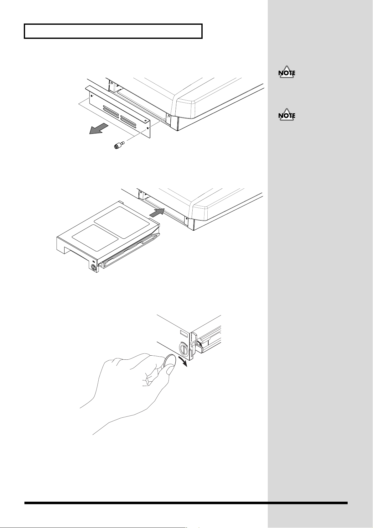
Remove the front panel cover from the VS-2480.
fig.01-02_50
With the warning label of the hard disk facing upward, slide it gently into
the installation bay as far as it will go. You can hook the indentation of the
attachment hardware over the protrusion on the chassis of the VS-2480.
fig.01-03_40
2.
3.
4.
5.
The hard disk inside the
VS-2480CD cannot be
removed or exchanged.
When transporting the
VS-2480, please pack it in
the original carton and
shock-absorbing material,
or the equivalent. If an
internal IDE hard disk
(HDP35 series) is installed,
reverse the installation
procedure to remove it
from the VS-2480, pack the
hard disk in its own
packing carton for
transport. If the VS-2480 is
transported with the hard
disk installed, project data
may be lost, or the hard
disk itself may be
damaged.
After you install the hard disk to the unit you use, please lock it to fix.
Apply a coin, etc. to the lock and turn it clockwise until it clicks and it is
locked correctly.
fig.01-04
LOCK
Reattach the front panel cover as it originally was.
6
Page 7

fig.01-05_50
6.
Preparations
As described in “ Turning On the Power (p. 19),” turn on the power and
verify that the VS-2480 starts up correctly.
If the Display Indicates “Not Found any Drives”
The internal hard disk was not recognized correctly. Use the rear panel power switch
to turn off the power (p. 23), and re-install the hard disk correctly.
fig.dialog-NotFoundDrive
When you turn on the
power after an unformatted
disk has been installed, the
"Format Drive" screen will
appear automatically.
Follow the displayed
instructions to format the
disk.
Preparations
7
Page 8
1.
Preparations
Installation de dispositifs optionnels
(French language for Canadian Safety Standard)
■
Précautions à prendre lors de l’installation de dispositifs optionnels
• Toujours éteindre et débrancher l’appareil avant de commencer l’installation
de la carte. (modèle no série HDP35; User Guide p. 23).
• N’installez que les cartes de disque dur spécifiées (modèle no série HDP35).
Enlevez seulement les vis indiquées.
• Veuillez suivre attentivement les instructions suivantes quand vous
manipulez la carte afin d’éviter tout risque d’endommagement des pièces
internes par l’électricité statique.
•Toujours toucher un objet métallique relié à la terre (comme un tuyau
par exemple) avant de manipuler la carte pour vous décharger de
l’électricité statique que vous auriez pu accumuler.
•Lorsque vous manipulez la carte, la tenir par les côtés. Évitez de
toucher aux composants ou aux connecteurs.
•Conservez le sachet d’origine dans lequel était la carte lors de l’envoi et
remettez la carte dedans si vous devez la ranger ou la transporter.
• Veillez à ne pas laisser tomber de vis dans le châssis du VS-2480.
• Ne pas toucher aux circuits imprimés ou aux connecteurs.
• Ne jamais forcer lors de l’installation de la carte de disque dur. Si la carte
s’ajuste mal au premier essai, enlevez la carte et recommencez l’installation.
• Quand l’installation de la carte de disque dur est terminée, revérifiez si tout
est bien installé.
■
Installer un disque dur (série HDP35)
Le VS-2480 s’utilise avec un disque dur Roland de la série HDP35 vendu séparément.
Pour maximiser les capacités du VS-2480 -nombre de pistes lors des enregistrements
et lectures simultanés ou taille de la mémoire-, il est conseillé d’utiliser un modèle
supérieur au 40 GB.
Éteindre tous les appareils reliés au VS-2480 et détacher tous les câbles qui
y sont reliés.
8
Page 9

2.
3.
4.
Enlever les vis indiquées sur le schéma suivant et détacher la plaque avant
du VS-2480.
fig.38
Orienter le disque dur de façon à ce que la face sur laquelle est collée
l’étiquette de mise en garde se trouve sur le dessus.
Preparations
Afin d’éviter d’infliger des
dommages à l’appareil lors
de déplacements, enlever le
disque dur installé en
suivant, dans le sens
contraire, les étapes de son
installation de la p. 6. Il est
impératif d’enlever le
disque dur du VS-2480 lors
de déménagement ou
d’envoi. Lors de tels
déplacements, ne pas
oublier de bien remettre le
disque dur dans son
emballage d’origine et de
placer le disque emballé
dans l’espace prévu à cet
effet dans la boîte
d’emballage du VS-2480.
Preparations
Après avoir installé le disque dur dans le VS-2480, fixez-le bien afin qu'il ne
se détache pas.
LOCK
9
Page 10

Preparations
Pour ce faire, insérez une pièce de monnaie dans la fente et tournez dans le
sens des aiguilles d'une montre jusqu'à ce que vous entendiez un déclic.
Cela signifie que le disque est bien fixé.
5.
6.
Les vis peuvent s’enlever avec les doigts. Si elles sont trop serrées pour être dévissées
avec les doigts, vous pouvez utiliser une pièce de monnaie.
Si le message “Not Found any Drives” s’affiche, cela signifie que le disque dur
installé n’est pas reconnu correctement. Éteindre l’appareil avec le bouton arrière et
recommencer l’installation du disque dur.
fig.01-06
10
Page 11

1.
Installing Effect Expansion Boards
2.
Preparations
The VS-2480/2480CD contains one VS8F-2 effect expansion board (EFFECT A
section).
An additional three VS8F-2 boards can be installed in the VS-2480/2480CD.
When four VS8F-2 boards are installed, you will be able to use up to eight stereo
effects simultaneously.
■
Cautions When Installing an Effect Expansion Board
lTo avoid the risk of damage to internal components that can be caused by static
electricity, please carefully observe the following whenever you handle the board.
• Before you touch the board, always first grasp a metal object (such as a water
pipe), so you are sure that any static electricity you might have been carrying
has been discharged.
• When handling the board, grasp it only by its edges. Avoid touching any of
the electronic components or connectors.
• Save the bag in which the board was originally shipped, and put the board
back into it whenever you need to store or transport it.
• Use a Phillips screwdriver that is suitable for the size of the screw (a number
2 screwdriver). If an unsuitable screwdriver is used, the head of the screw
may be stripped.
• To remove a screw, rotate the screwdriver
counter-clockwise. To tighten a screw, rotate the
screwdriver clockwise.
fig.01-07j
• When installing effect expansion boards,
remove only the specified screws.
• Be careful that the screws you remove do not drop into the interior of the
VS-2480/2480CD.
• Do not leave the bottom cover in a detached state. Be sure to reattach it after
the effect expansion boards have been installed.
• Do not touch any of the printed circuit pathways or connection terminals.
• Be careful not to cut your hand on the edge of the installation bay.
• Never use excessive force when installing a circuit board. If it doesn’t fit
properly on the first attempt, remove the board and try again.
• When circuit board installation is complete, double-check your work.
Preparations
tightenloosen
Before installing the VS8F-2, turn off the power of the VS-2480/2480CD
and all connected devices, and disconnect all cables from the
VS-2480/2480CD.
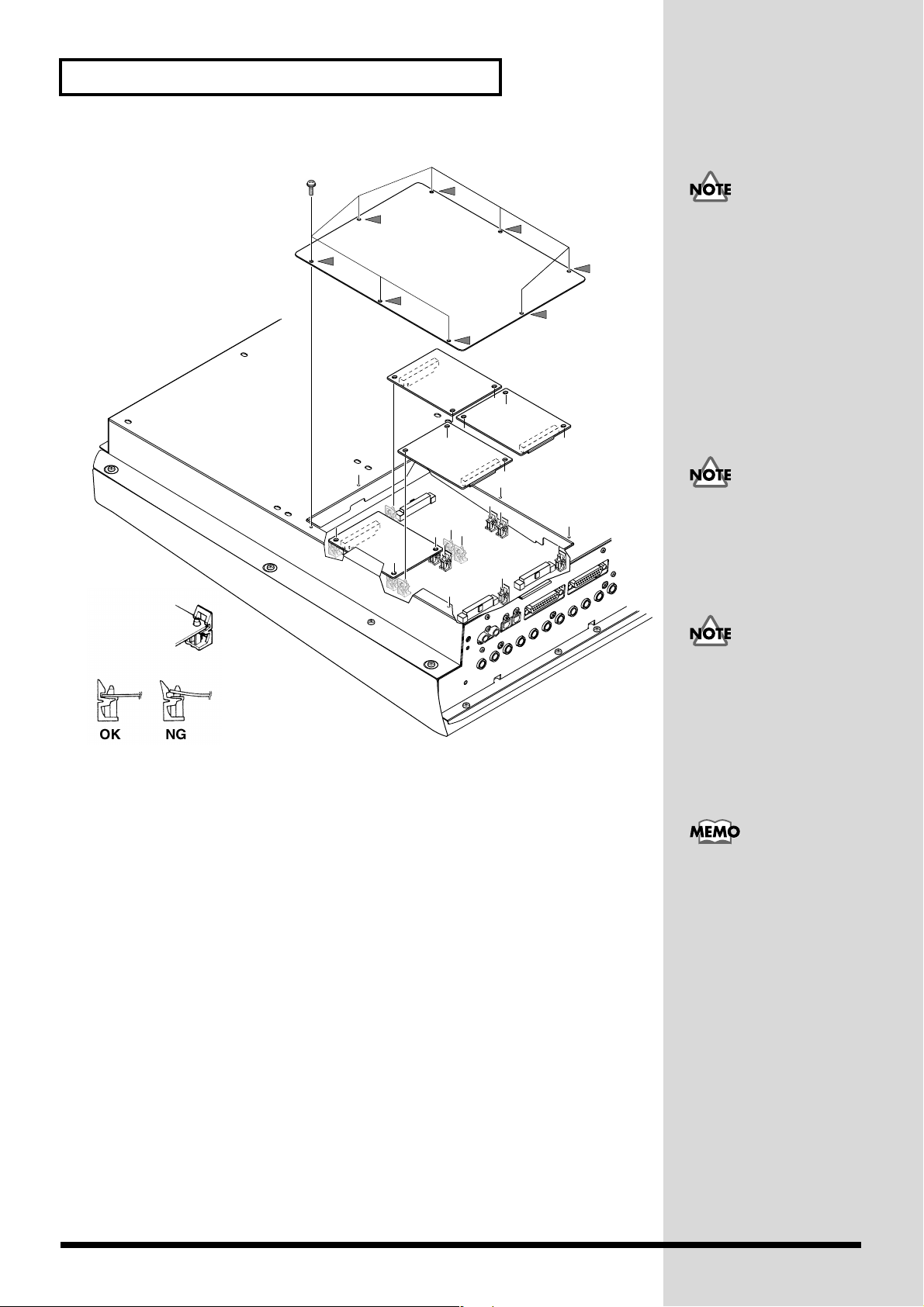
Turn the VS-2480/2480CD on its back, and remove only the screws shown
in the following diagram.
11
Page 12
Preparations
b
b
b
b
fig.01-08_50
EFFECT B
3.
4.
EFFECT D
5.
6.
7.
When turning the unit
upside-down, get a bunch
of newspapers or
magazines, and place them
under the four corners or at
oth ends to prevent
damage to the buttons and
controls. Also, you should
try to orient the unit so no
uttons or controls get
damaged.
EFFECT C
EFFECT A
Inside, there are four connectors and 12 resin pins. Insert the connectors of
the VS8F-2 in to the internal connectors, and simultaneously insert the resin
pins into the holes of the VS8F-2 to fasten the unit in place.
Use the screws that you removed in step 2 to fasten the cover back in place.
This completes installation of the effect expansion board.
Connect the cables that you disconnected earlier.
Turn on the power, as described in “ Turning On the Power (p. 19).”
When turning the unit
upside-down, handle with
care to avoid dropping it,
or allowing it to fall or tip
over.
Install VS8F-2 effect
expansion boards in the
order of EFFECT A,
EFFECT B, EFFECT C, and
EFFECT D. Do not skip
slots when installing these
oards.
The VS-2480/2480CD
comes equipped with one
internal effects expansion
oard (containing two
effects processors).
After proper startup of the VS-2480/2480CD, press [EFFECT] and confirm
that the FX 1 and 2 icons are displayed. If two VS8F-2 units are installed,
press [EFFECT] and confirm that the icons for FX 1–4 are displayed.
12
Page 13

fig.01-09(FXAssign)
If the Display Indicates “No EFFECT Board”
The internal effect expansion board was not detected correctly. Turn off the power
(Shutdown operation), as described in “Turning Off the Power (p. 23),” and
re-install the effect expansion board correctly.
Preparations
Preparations
13
Page 14

Preparations
Installation de la carte d’extension d’effets
(French language for Canadian Safety Standard)
Quand une ou deux cartes VS8F-2 sont installées, il est possible d’utiliser jusqu’à 2
effets stéréo pour chaque carte sans brancher aucun équipement additionnel au
VS-2480/2480CD. Deux de ces cartes peuvent être installées dans le
VS-2480/2480CD. Il est recommandé d’installer au moins une carte d’extension à
effet pour pouvoir utiliser pleinement le VS-2480/2480CD.
■
Précautions lors de l’installation de la carte d’extension d’effets
Pour éviter tout dommage des composants internes pouvant provenir de
l’électricité statique, veuillez suivre les conseils suivants quand vous installez la
carte.
• Avant de toucher la carte, saisissez toujours un objet métallique (tuyau d’eau
ou autre) pour être sûr que l’électricité statique se décharge.
• Quand vous saisissez la carte, prenez-la par les bords. Evitez de toucher les
composants électroniques ou les connecteurs.
• Conservez le sac dans lequel la carte était emballée et remettez la carte
dedans pour l’expédier ou l’entreposer.
●
Utiliser un tournevis cruciforme correspondant à la taille de la vis (un tournevis
numéro 2). En cas d’utilisation d’un tournevis inapproprié, la tête de la vis pourrait
être endommagée.
●
Pour enlever les vis, tourner le tournevis dans
le sens contraire des aiguilles d’une montre. Pour
resserrer, tourner dans le sens des aiguilles d’une
montre.
●
Lors de l’insertion de la carte d’extension
d’effets, enlevez seulement les vis indiquées dans les instructions.
●
Veillez à ne pas laisser tomber de vis dans le châssis du VS-2480/2480CD.
●
Ne pas laisser le panneau de protection avant détaché. S’assurer de l’avoir
rattacher après avoir installé le disque dur.
●
Ne touchez aucun des circuits imprimés ni les bornes de connexion.
●
Veillez à ne pas vous couper les doitgs sur le bord de l’ouverture d’installation.
●
Ne jamais forcer quand vous installez une carte de circuits. Si la carte ne rentre pas
correctement, ressortez-la et ressayez.
●
Quand la carte est installée, vérifiez si l’installation est correcte.
resserrerdesserrer
●
1.
Lorsque vous retournez à
l'envers le
VS-2480/2480CD, posez-le
sur une surface molle afin
de ne pas abîmer le tableau
de commande ou l'écran de
commande. Retournez le
VS-2480/2480CD et
enlevez seulement les vis
indiquées sur la figure.
14
Éteindre le VS-2480/2480CD et tous les appareils qui y sont reliés et
débrancher tous les câbles du VS-2480/2480CD.
Page 15

A l’intérieur se trouvent deux connecteurs et 12 goupilles de plastique.
Reliez les connecteurs de la VS8F-2 à ceux du VS-2480/2480CD tout en
insérant les goupilles de plastique dans les orifices de la VS8F-2.
fig.1-05.f
EFFECT B
2.
3.
4.
5.
6.
Preparations
Si vous installez une seule
carte d’extension d’effets,
installez-la dans
EFFECT A.
Preparations
EFFECT D
EFFECT C
EFFECT A
Reposez le couvercle en remettant les vis enlevées (comme spécifié) à
l’étape 2. L’installation de la carte d’extension d’effets est terminée.
Rabranchez les câbles.
Mettez le VS-2480/2480CD sous tension en procédant comme indiqué dans
“ Turning On the Power (p. 19).”
Si le VS-2480/2480CD démarre normalement, appuyez sur la touche
[EFFECT] et assurez-vous que les icônes FX 1,2 s'affichent. Si vous avez
installé deux VS8F-2, lorsque vous appuyez sur la touche [EFFECT] ,
assurez-vous que les icônes FX 1--4 s'affichent.
Si “No EFFECT Board” apparaît à l’écran
Ce message signifie que la carte d’extension d’effets n’a pas été reconnue
correctement. Mettez l’appareil hors service et hors tension comme indiqué
dans “Mise hors tension”, puis réinstallez correctement le VS8F-2.
15
Page 16

Preparations
How to Replace the Battery
A lithium battery inside the unit powers its time-keeping functions, and provides the
power for maintaining information about certain parameters. Once this battery gets
weak, the unit may no longer be able to reliably perform the time management
functions for data, or return to the state is was in before power was turned off. If you
see a message warning that the battery is depleted, promptly change the battery,
following the procedure below.
fig.01-10(BattLow)
1.
2.
3.
Before changing the lithium battery, store the current project (p. 49).
Turn off the power of VS-2480/2480CD and all connected devices, and
disconnect all cables from VS-2480/2480CD.
Turn the VS-2480/2480CD on its back, and remove only the screws shown
in the following diagram.
fig.01-10a_50
16
Page 17

fig.battery1_69
b
b
Preparations
4.
5.
6.
Preparations
The battery should now be visible, as shown in the following.
fig.battery2_69
CR2032
CR2032
When turning the unit
upside-down, get a bunch
of newspapers or
magazines, and place them
under the four corners or at
oth ends to prevent
damage to the buttons and
controls. Also, you should
try to orient the unit so no
uttons or controls get
damaged.
If Effect Expansion Board (VS8F-2) installed on the EFFECT A section,
remove the VS8F-2 of the EFFECT A section.
Replace the old battery with a new one.
17
Page 18

Preparations
b
b
fig.battery3_69
7. Reinstall the effect expansion board (VS8F-2) if removed in Step 5. Insert
the plastic pin in the VS8F-2’s hole, making sure the board is securely
fastened in place.
8. Use the screws that you removed in step 2 to fasten the cover back in place.
This completes the process of exchanging the lithium battery.
9. Connect the cables that you disconnected earlier.
10. Turn on the power, as described in “Turning On the Power (p. 19).”
11. Confirm that the message warning that the lithium battery is depleted does
not appear in the display.
12. Set the current time (p. 22).
Basic Connections (Power Supply, Audio
A CR2032 lithium battery is
used for the
VS-2480/2480CD. This type
of battery is available at an
electric appliance, or
similar store.
The internal clock is
powered by the lithium
attery. Changing the
lithium battery may cause
this clock to stop, or may
result in the current time
eing altered. Always
make sure to newly set the
correct time after the
lithium battery has been
replaced.
Devices and Headphones)
fig.01-11j_60
POWER
ON
AC IN
To Power Outlet Ground (Earth)
THIS DEVICE COMPLIES WITH PART 15 OF
THE FCC RULES. OPERATION IS SUBJECT
TO THE FOLLOWING TWO CONDITIONS:
(1)
THIS DEVICE MAY NOT CAUSE HARMFUL
INTERFERENCE, AND (2) THIS DEVICE MUST
ACCEPT ANY INTERFERENCE RECEIVED,
INCLUDING INTERFERENCE THAT MAY
CAUSE UNDESIRED OPERATION.
SMPTE
IN
MIDI
PS/2
KEYBOARD
MOUSE
SCSI
VGA OUT
Stereo Headphones
(RH-25, RH-50, etc.)
INOUT/THRU
WORD CLOCK IN
FOOT
SWITCH
2
+
4dBu BALANCED/-2dBu UNBALANCED
ANALOG MULTI OUTPUT
RLRLRL
MONITOR AUX AAUX B
DIGITAL
1
OUT IN
DIGITAL 8ch I/ODIGITAL 8ch I/O
OPTICAL
Stereo Set, etc.
34
125678PHONES 1PHONES 2
COLDGND
(
)
(
)
SLEEVE
RING
HOT
(
)
TIP
RL
MASTER
OUT IN
COAXIAL
If you are using headphones, connect them to the rear panel PHONES 1 or PHONES
2 jack. The PHONES jack will output the same signal as the MONITOR jacks.
When you purchase the VS-2480/2480CD, it will be set so that all analog audio
signals are output from the MASTER jacks. The MONITOR jacks will output the
same sound as the MASTER jacks.
fig.01-12
18
For details refer to Owner’s
Manual “Working with the
VS-2480 Output. (p. 287)”
Page 19

Preparations
b
b
b
Be sure to ground the device to prevent any minor leakage of current from the
VS-2480/2480CD, connectors, or other possible sources.
The VS-2480/2480CD Support the “Mouse” and
the “VGA Monitor”
The VS-2480/2480CD has a “Mouse connector” that allows a mouse to be connected.
If a mouse is connected, you will be able to use a mouse to operate the buttons and
control knobs that appear in the display of the VS-2480/2480CD.
If a personal computer VGA monitor is connected to the “VGA connector,” you can
view your operations on a larger screen than the display built into the
VS-2480/2480CD
Turning On the Power
1. The rear panel POWER switch
turns on the power of the
VS-2480/2480CD. Use the rear
panel POWER switch to turn on the
power of the VS-2480/2480CD. The
current system version number will
be displayed with the opening
screen. Please wait.
fig.01-13
2. When the VS-2480/2480CD starts
up correctly, the following display
(Home Condition screen) will
appear.
3. Turn on the power of your audio
system.
4. Raise the volume of your audio
system to an appropriate level.
Always make sure to have the volume level turned down before switching
on power. Even with the volume all the way down, you may still hear some
sound when the power is switched on, but this is normal, and does not
indicate a malfunction.
System Version #
To prevent malfunction
and/or damage to speakers
or other devices, always
turn down the volume
efore making any
connections.
Do not connect a mouse to
the keyboard connector. It
ecomes the cause of
malfunction.
Once the connections have
een completed (p. 18),
turn on power to your
various devices in the order
specified. By turning on
devices in the wrong order,
you risk causing
malfunction and/or
damage to speakers and
other devices.
When the power is turned
on, the disk drive will be
detected, and necessary
data will be read. For this
reason there will be an
interval of time before
operation can begin.
Preparations
19
Page 20

Preparations
■ Adjusting the Display Contrast
fig.01-14_50
The text or icons in the VS-2480/2480CD’s display (Operation
Display) may be difficult to read immediately after the unit is turned
CONTRAST
PHONES 1
on or after it has been used for long periods, or depending on the
environment in which the unit is used. If this occurs, rotate the
010
PHONES 2
CONTRAST knob located at the left side of the display to adjust the
display contrast.
010
MONITOR
■ If You Do Not Understand the Display or Don’t Know What to Do
fig.01-15
DISPLAY
F4 F5 F6 HOME
If an unfamiliar display appears or
if you do not know how you arrived
at the current condition, press
[HOME (DISPLAY)]. This will
return you to the initial power-on
screen, allowing you to re-do the
procedure from the beginning.
Operating the CONTRAST
knob will not affect the
screen displayed by the
VGA monitor connected to
the VGA connector.
Mixer and Utility Parameters Initialize
You can restore the default parameter settings of a project. This is convenient when
you have made many changes to the Input Mixer, the Track Mixer, the Master Block,
as well as changes in the System Menu screens, and you want to quickly restore the
VS-2480/2480CD to its default settings.
• If you attempt to perform an incorrect operation or if the specified operation
cannot be executed, an error message will appear in the display. Please refer
to “Error Messages” (Appendices p. 9) and take the appropriate action.
• If the results are not as described in the User Guide or Owner’s Manual even
though you have followed the specified steps, please refer to
“Troubleshooting” (Appendices p. 5).
• If the information in “Troubleshooting” does not resolve the problem,
contact a nearby Roland Service Center or authorized Roland Distributor.
After initializing mixer and
system settings, many
settings will not be
affected. Some of the
settings that are not
affected by Mixer and
System Initialize include
project, Scene, tempo map,
and sync track data.
Additionally, the IDE
drive, SCSI ID, Scene
Mode, Shift Lock, and
Numerics Type settings are
not changed as a result of
Mixer/System Initialize.
20
Page 21

fig.01-17_50
5
3
2
PAGE F1 F2 F3 F4 F5 F6 HOME
DISPLAY
Preparations
Preparations
EZ
ROUTING
COPY MOVE TRIM IN TRIM OUT DELETE SPLIT NEW
PATCH BAY
COPY MOVE INSERT CUT ERASE COMP / EXP.
AUTOMIX
CD-RW
MASTERING
PROJECT TRACK EFFECT UTILITY
1
LOCATOR / MARKER / SCENE
LOCATOR
BANK AUX 7 AUX 8 USER
MARKER
4
AUX 4 AUX 5 AUX 6
1
AUX 1 AUX 2 AUX 3
PREVIOUS NEXT
PREVIEW
TO THRU
SCRUB
ZERO STOP PLAY REC
SHUT / EJECT
MENU
56
0
/-
TRACK EDIT
LOOPA.PUNCH TOOUTIN FROM
MIDI DISK
/
SCENE
987
BANK
IMPORT
GRADATION
WAVE DISP
+
ZOOM
TIME / VALUE
SHUTTLE
+
PHRASE
REGION
AUTOMIX
UNDO
REDO
32
SHIFT
FROM
PROJECT ENDPROJECT TOP
EXT SYNC
AUTOMIX RECRESTARTSTORE
ENTER
YES NO
/ /
4
EXIT
6 6
1. Press [UTILITY]. Utility Menu screen will appear.
2. Press [PAGE] several times until function tab “Page3” will be appeared at
the front.
3. Press [F6 (PrmIni)]. MIXER/UTILITY Parameter Initialize screen will
appear.
4. Use TIME/VALUE dial to select the parameter that you wish to initialize.
5. Press [F5 (OK)].
6. “Initialize Parameter?” message will appear. If you wish to initialize, press
[ENTER/YES]. If you wish to cancel the operation, press [EXIT/NO].
fig.dialog-initparam
21
Page 22

Preparations
Setting the Date and Time of the Internal Clock
The VS-2480/2480CD contains a clock. When you record a performance, a time
stamp is added which indicates the date and time of the recording. This is a
convenience that helps you keep track of the date or order in which recordings were
made. After turning on the power for the first time after purchase, please use the
following procedure to set the date and time of the internal clock.
fig.01-19_50
IMPORT
GRADATION
WAVE DISP
+
ZOOM
TIME / VALUE
SHUTTLE
4
6
DISPLAY
+
PHRASE
REGION
AUTOMIX
UNDO
REDO
4
2
PAGE F1 F2 F3 F4 F5 F6 HOME
EZ
ROUTING
PATCH BAY
AUTOMIX
CD-RW
MASTERING
1
LOCATOR
BANK AUX 7 AUX 8 USER
MARKER
COPY MOVE TRIM IN TRIM OUT DELETE SPLIT NEW
COPY MOVE INSERT CUT ERASE COMP / EXP.
PROJECT TRACK EFFECT UTILITY
LOCATOR / MARKER / SCENE
PREVIOUS NEXT
MENU
56
4
AUX 4 AUX 5 AUX 6
1
AUX 1 AUX 2 AUX 3
0
/-
TRACK EDIT
MIDI DISK
SCENE
987
BANK
32
3,5
LOOPA.PUNCH TOOUTIN FROM
/
SHIFT
1. Press [UTILITY]. Utility Menu screen will appear.
2. Press [PAGE] several times until function tab “Page3” will be appeared at
the front.
3. Press [F5 (DATE)].
4. Use [][][][] to move the cursor. Use TIME/VALUE dial
to set each value.
Date Edit
Set the year, month, and day.
Date Format
Select how the date will be displayed. (The examples shown here are for February 1,
2001.)
mm/dd/yyyy: month/day/year (Example: 02/01/2001)
dd/mm/yyyy: day/month/year (Example: 01/02/2001)
yyyy/mm/dd: year/month/day (Example: 2001/02/01)
MMM. dd, ‘YY: month/day/year (Example: Feb. 01, ‘01)
dd MMM ‘YY: day/month/year (Example: 01 Feb ‘01)
Time Edit
Set the current time in 24-hour format.
5. After setting the date the time, press [F5 (SET)] at the moment that the
specified time arrives. The specified time will take effect at that moment.
6. Press [HOME (DISPLAY)]. Home Condition screen will appear.
The internal clock operates
on a battery. There is no
need to perform this
operation the second and
subsequent times you turn
on the VS-2480/2480CD.
However, you may set the
clock again if for some
reason it should become
inaccurate.
22
Page 23

Turning Off the Power
Preparations
If you simply turn off the power, not only can recorded content be lost, but the
VS-2480/2480CD itself could malfunction. In order to safeguard the recorded
performance and turn off the power safely, you must perform the Shutdown
procedure when you are finished.
fig.01-20_50
1
AUX 1 AUX 2 AUX 3
PREVIOUS NEXT
PREVIEW
TO THRU
SCRUB
ZERO STOP PLAY REC
SHUT / EJECT
1
32
EXT SYNC
AUTOMIX RECRESTARTSTORE
SHIFT
ENTER
YES NO
/ /
EXIT
/-
0
FROM
PROJECT ENDPROJECT TOP
42,4
1. Hold [SHIFT] and press [SHUT/EJECT (STOP)]. “SHUTDOWN/EJECT?”
message will appear.
fig.dialog-shutdown
Preparations
Shutdown (Appendices p.
13)
2. Press [ENTER/YES].
3. “STORE Current?” message will appear.
fig.dialog-current store
4. If you wish to store the currently selected project, press [ENTER/YES]. If
you do not need to save it, press [EXIT/NO]. However, this display will not
appear in the case of a demo performance or if the project is protected (i.e.,
cannot be edited).
5. When the shutdown procedure ends correctly, the display will indicate
“POWER OFF / RESTART” (turn off the power / restart).
Current Project
(Appendices p. 12)
For details refer to Owner’s
manual Project and Drive
Operations –“PROTECT (p.
75)”.
23
Page 24

Preparations
fig.dialog-poweroff
6. Lower the volume of your audio equipment.
7. Turn off the power of your audio equipment.
8. Use the rear panel POWER switch to turn off the VS-2480/2480CD.
If “STORE Current?” is Displayed
When you execute various operations (including Shutdown), “STORE Current?”
(Store the current project?) may be displayed. This message asks whether or not you
wish to store the currently selected project to disk. If you wish to store the project
before continuing with the operation, press [ENTER/YES]. If you do not need to save
the project (i.e., if you wish to discard the recording and editing that was done up to
that point, and revert to the condition in which the project was last saved), press
[EXIT/NO].
fig.dialog-current store
After the power is turned
off, the hard disk will
continue rotating for a time
due to inertia. During this
time, applying physical
shock to the
VS-2480/2480CD may
damage the disk. Before
moving a VS-2480/2480CD
that contains a hard disk,
wait approximately a few
seconds after turning off
the power.
24
Page 25

Listening to the Demo Performance
A demo performance needs to be Recovered from CD-ROM of a belonging. Also, the
CD-R/RW drive such as the Roland CD Recorder is necessary to the Recover. For
details please see the leaflet “To Recover the demo performance” of a belonging.
If you are using a VS-2480 that does not have an internal CD-RW drive, you will need a
separately sold CD-RW drive (Roland CD Recorder).
A number of demo performances were placed on the hard disk inside the
VS-2480CD before it left the factory.
How To Load a Demo Song (CD-R Recover)
1. Turn off the power supply of all apparatus.
2. -1. Connect the VS-2480 with the Roland CD Recorder according to
“Connecting the CD-R/RW Drive (p. 82)”
-2. Turn on the power of the Roland CD Recorder.
-3. Insert a attached CD in the Roland CD Recorder.
Using these demo
performance for any
purpose other than
personal enjoyment
without permission of the
copyright owner is
prohibited by law.
Listening to the Demo
Performance
3. Turn on the power of the VS-2480 (rear panel).
4. Press [PROJECT]. Project list appears.
5. Use the TIME/VALUE dial to move the cursor to the drive in which the
demo CD-ROM is inserted.
6. Press [F6 (LIST)]. “Change Current Drive?” message appears.
7. Press [ENTER/YES]. “Store Current?” message appears.
8. If you wish to save the current project, press [ENTER/YES]. If not, press
[EXIT/NO].
9. Use the TIME/VALUE dial to move the cursor to the demo project that you
wish to recover.
10. Press Page 3 [F2 (Recovr)]. Project
Recover screen appears.
• CD Speed
Select the speed at which data
will be read from a CD-R/RW
disc. This parameter will be
displayed only if a CD-R/RW
drive is selected as the read
source.
• Erase All Projects
Off—if you want to add the project(s) you’re recovering to the list of projects
already on the destination drive.
On—if you want to clear the drive so it contains only your recovered
In the case of usage, an
optional the Roland CD
Recorder is required in
VS-2480 which do not build
in the CD-RW drive.
25
Page 26

Listening to the Demo Performance
projects.
11. Select the recovery-destination. Press [F4 (SelDrv)].
Use the TIME/VALUE dial to move the cursor to the recovery-destination,
and press [F5 (SELECT)]. If you change your mind about the drive
selection, press [F6 (CANCEL)].
12. Press [F5 (OK)]. “Recover from SCSIx Sure?” (x is SCSI ID number)
message is displayed.
13. Press [ENTER/YES]. Loading of data starts. If loading finishes, it will
return to a home condition screen.
If a disc tray does not open
If the power is turned off with the disc still in the drive (such as due to a
power failure), the disc tray cannot be opened by pressing the eject
button. In this case, you can insert a piece of wire to force the tray open.
1. Turn off the power of the VS-2480CD.
2. Insert a thin object such as a wire into the emergency eject hole.
The disc tray will open.
Make sure the VS-2480CD's
power has been turned
OFF before attempting to
use the emergency eject
hole. If you insert
something while the power
is on, the disc could get
damaged, or unexpected
problems may occur.
Emergency Eject Hole
26
Page 27

Listening to the Demo Performance
E
S
b
For Making the Preparations Which Listen to a Demo Performance (Project Select)
Select a demo song, when you listen to a demo performance. Use the
following procedure to select a project.
fig.2-05
1. Press [PROJECT]. Project List screen
appears.
2. Use the TIME/VALUE dial to move
the cursor to the project that you
want to listen to the demo project.
fig.sel-demo_73
3. Press [PAGE] several times until
function tab “Page1” will display at
the front.
EZ
ROUTING
PATCH BAY
AUTOMIX
CD-RW
MASTERING
COPY MOVE TRIM IN TRIM OUT DELE T
COPY MOVE INSERT CUT ERASE
A.PUNCH TOOUTIN FROM
PROJECT TRACK EFFECT UTILIT Y
MENU
TRACK EDIT
MIDI DI
Using these demo
performance for any
purpose other than
personal enjoyment
Listening to the Demo
Performance
without permission of the
/
copyright owner is
prohibited by law.
4. Press [F1 (SELECT)]. “Select Project,
Sure?” message appears.
5. Press [ENTER/YES]. “STORE
Current?” message appears.
6. If you wish to save the current project, press [ENTER/YES]. If not, press
[EXIT/NO].
7. The project will be selected, and you will return to the home condition
display.
The demo projects are
protected so that their
content cannot be modified
(Project Protect) (Owner’s
manual p. 48). They cannot
e recorded, edited, or
stored. If a demo
performance or a project
for which Project Protect is
turned on has been
selected, the “STORE
Current?” message will not
appear, so you can skip
step 6.
27
Page 28

Listening to the Demo Performance
SOLO
FROM
MUTE
///
/
Playing Back the Demo Performance
fig.02-01_30
3
TO
TRACK
REC
PLAY
OFF
PHRASE
PAD
(dB)
6
R
4
0
4
8
12
18
24
42
L
TRACK STATUS / PHRASE PAD
/
9121172183194205216227238
AUX 2
AUX1
MST AUX 3 AUX 4 AUX 5 AUX 6 AUX 7 AUX 8
24
RTN
13 14 15 1610 11
FX 2FX1 FX 3 FX 4 FX 5 FX 6 FX 7 FX 8
TR 1-16
MASTER
EDIT
FADER
MASTER
(dB)
6
4
0
4
8
12
18
24
42
TR 17-24
FX RTN
V.FADER
1
R
L
4,6
1. Press [TR 1-16 (MASTER EDIT)]. [TR 1-16 (MASTER EDIT)] indicator will
light, the channel fader will adjust to the Track Mixer level of channel 1–16.
fig.02-02_50
CONTRAST
2. Set the MONITOR knob to the 0 dB position (3 o’clock).
3. Set all channel faders to the 0 dB position.
4. Lower the master fader to the lowest position.
5. Press [PLAY]. The demo performance will play back, and
the playback time, level meters, and the playback state of
each track (play list) will begin moving.
PHONES 1
010
PHONES 2
010
MONITOR
7
7
Using these demo
performance for any
purpose other than
personal enjoyment
without permission of the
copyright owner is
prohibited by law.
If you set the Track Mixer
17–24, press [TR 17-24/FX
RTN (V.FADER)].
6. Slowly raise the master fader to adjust the volume. The
playback time, level masters, and playback status of each
track (playlist) etc. will be displayed.
fig.02-03
7. To adjust the volume of the
headphones, rotate the PHONES 1 or
ZERO STOP PLAY REC
SHUT / EJECT
the PHONES 2 knob.
8
5
8. When you finish demo performance,
press [STOP]. The demo performance will stop.
■ Viewing the Level Meters.
fig.02-04_50
1. Press [HOME (DISPLAY)].
Home Condition screen
will appear.
2. Press [F3 (TR Mix)]. At this time, the level meters will show the volume
level of the playback tracks.
This switches the type of level meters displayed for the function buttons in home
condition.
[F1 (INPUT)] Levels being input to the input jacks
[F2 (IN Mix)] Levels being input to the input mixer
[F3 (TR Mix)] Track mixer levels
[F4 (AUXDIR)] Signal levels flowing through AUX bus and direct path
[F5 (OUTPUT)] Levels being output to the output jacks
F1 F2 F3 F4 F5 F6
23
2
AUTOMIX RECRESTARTSTORE
DISPLAY
HOME
1
28
Page 29

Listening to the Demo Performance
3. Press [F6 (To Pre)] to select pre level display, and press [F6 (To Pst)] once
again to select post level display, alternately (except from the INPUT
display or OUTPUT display).
The upper part of the level meter will indicate whether the current display is the pre
level or the post level.
When pre level display, since this shows the volume levels before the signal passes
through the channel faders, the level meter display will not change when you
operate the channel faders.
When post level display, since this shows the volume levels after the signal passes
through the channel faders, the level meter display will be affected when you
operate the channel faders.
fig.02-05
Listening to the Demo
Performance
The MONITOR level and
MASTER level are always
displayed as Post level.
■ Adjusting the Overall Volume
To adjust the overall volume of the performance, use the MASTER fader or the
MONITOR knob.
■ Adjusting the Volume of an Individual Track
To adjust the volume of an individual track press [TR 1-16 (MASTER EDIT)], so that
the [TR 1-16 (MASTER EDIT)] indicator will light, and use the channel faders.
If you wish to adjust the track of channel 17–24, press
(V.FADER)]
the channel faders.
, so that the
[TR 17-24 / FX RTN (V.FADER)]
[TR 17-24 / FX RTN
indicator will light, and use
■ Adjusting the Headphone Volume
To adjust the volume of the headphones, use the PHONES 1 or the PHONES 2 knob.
For details refer to “Mixer
Section Block Diagram”
(accessory sheet).
29
Page 30

Listening to the Demo Performance
+
b
Listening to the Demo Performance with a Different Arrangement (Scene)
Demo performance contain several completely different sets of settings for pan,
playback track, and effects etc. These settings are collectively called a scene. By
recalling different scenes or changing the scene while you playback a demo
performance, you can hear the demo performance arranged in different ways. Here’s
how you can listen to various arrangements of the demo.
fig.02-06_50
LOCATOR
MARKER
4,5
LOCATOR / MARKER / SCENE
BANK AUX 7 AUX 8 USER
56
4
AUX 4 AUX 5 AUX 6 AUX 1-8
TAP
1
SNAPSHOT
SCRUB
AUX 1 AUX 2 AUX 3
PREVIOUS NEXT
JUMP
TO THRU
PREVIEW
/-
0
PROJECT ENDPROJECT TOP
987
32
FROM
SCENE
BANK
KNOB/ FDR
ASSIGN
NUMERICS
CLEAR
EXT SYNC
SHIFT
ENTER EXIT
YES NO
/ /
ZOOM
TIME / VALUE
SHUTTLE
+
2
3
For details refer to Owner’s
Manual “Using Digital
Mixer.”
Since there are ten scene
anks (0–9), and each of
them holds ten scenes,
numbered from 0 to 9, a
total of 100 scenes can be
registered.
If [SCENE] indicator is
already lighted, you may
skip steps 2.
ZERO STOP PLAY REC
SHUT / EJECT
1,7
6
AUTOMIX RECRESTARTSTORE
1. Press [STOP].
2. Press [SCENE]. [SCENE] indicator will light.
3. Hold [SHIFT] and press [BANK (SCENE)]. The numerics buttons ([0]–[9])
will blink (current BANK number will light).
4. Press the numerics buttons ([0]–[9]) to select the scene bank. For this
example, press [0]. Select the scene bank 0. Buttons [0]–[9] will light to
indicate the scenes that are registered in scene bank 0.
5. Of the [0]–[9] buttons, press any that has a lighted indicator. The scene will
be recalled, and the settings of the VS-2480/2480CD will change.
6. Press [PLAY]. The project will playback. Notice that the arrangement of the
demo performance is different.
7. Press [STOP]. Playback will stop.
8. Repeat step 2–7 to hear and compare various arrangements of the demo
performance.
If scene bank number 0 is
already selected, you may
skip steps 3–4.
To delete a previously
registered scene, press
[CLEAR] and then a
previously registered [0]–
[9] button (i.e., one whose
indicator is lit).
Scenes are registered for
numeric keys that are lit.
Please stop playback before
you switch scenes.
30
Page 31

Making a Multi-Track Recording
b
b
This chapter explains the basic procedure for recording on the VS-2480/2480CD.
Please follow through these steps to understand the procedure.
Creating a New Project (Project New)
Regarding Hard Disk Partition Size
When purchased, the hard disk (HDP35 series) is divided (partitioned) into 10 GB
units. You can also select 500 MB, 1 GB, or 2 GB disks that are compatible with the
Roland VS series.
The changed partition size will take effect when you initialize (Initializing a drive
(Owner’s Manual p. 84)) the hard disk.
For example, if you change the partition size before you begin the procedures
(multitrack recording) described in this chapter, you will be able to record for a
longer time. However, all contents saved on the hard disk will be lost, and cannot be
recovered. As necessary, please back up (Owner’s Manual p. 80) the your works
beforehand on a external removable disk or CD-RW disc.
fig.03-01_50
2
PAG E F1 F2 F3 F4 F5 F6 HOME
EZ
ROUTING
COPY MOVE TRIM IN TRIM OUT DELETE SPLIT NEW
PATCH BAY
COPY MOVE INSERT CUT ERASE COMP / EXP.
AUTOMIX
CD-RW
MASTERING
PROJECT TRACK EFFECT UTILIT Y
1
LOCATOR / MARKER / SCENE
LOCATOR SCENE
BANK AUX 7 AUX 8 USER BANK
1. Press [PROJECT]. Project Condition screen will appear.
2. Press [PAGE] several times until function tab “Page1” will display at the
front.
3. Press [F2 (NEW)].
3
MENU
DISPLAY
TRACK EDIT
LOOPA.PUNCH TOOUTIN FROM
MIDI DISK
/
987
IMPORT
GRADATION
WAVE DISP
+
ZOOM
+
PHRASE
REGION
AUTOMIX
UNDO
REDO
4
5
Zip drive (Appendices p.
14)
Recording operations
cannot be performed when
the demo performance or
protected project (Project
Protect (Owner’s Manual p.
75)) is selected. This is
ecause the is protected so
that its contents cannot be
modified. In order to
record, use the following
procedure to prepare a new
project. This is analogous to
putting a new tape into a
tape-type multi-track
recorder.
The HDP35 series cannot
e used in the earlier VS
models
(VS-880/880EX/890/1680/
1880/1824/1824CD, and
VSR-880).
Making a Multi-Track
Recording
4. Assign a name to the project. Use [][] to highlight the character
you wish to change, and use the TIME/VALUE dial to select a character.
5. Use [] to move the cursor to “Sample Rate.”
About the number of tracks
available for simultaneous
recording and playback
(Owner’s Manual p. 14).
31
Page 32

Making a Multi-Track Recording
fig.03-01_50
6. Use TIME/VALUE dial to select the Sample
3F4F5F6 HOME
9
Rate (96kHz, 88.2kHz, 64kHz, 48kHz,
44.1kHz, 32kHz). Normally, choose “44.1k.”
7. Press [] to move the cursor to “Record
TRACK EDIT
TRIM OUT DELETE SPLIT NEW
CUT ERASE COMP / EXP.
IMPORT
GRADATION
LOOPTOFROM
WAVE DISP
Mode.”
UTILITY
MIDI DISK
SCENE
BANK
/
ZOOM
TIME / VALUE
SHUTTLE
8. Use TIME/VALUE dial to select the
Recording Mode (M24, MTP, CDR, M16,
MT1, MT2, LIV, LV2). Normally, choose
“MTP.”
9. Press [F5 (OK)]. “STORE Current?” message
EXT SYNC
SHIFT
ENTER EX IT
YES NO
/ /
will appear.
6,8
REC
AUTOMIX REC
10 10
store
fig.dialog- current
10. If you wish to store the current project, press [ENTER/YES]. If not, press
[EXIT/NO].
11. Home Condition screen will appear.
DISPLAY
When 96kHz, 88.2kHz or
64kHz is selected and M24,
PHRASE
REGION
AUTOMIX
UNDO
REDO
M16 or CDR is selected,
simultaneous
recording/playback is
limited to eight tracks.
+
+
7
For details refer to Owner’s
Manual “About Recording
Mode.” (Owner’s Manual
p. 74)
The demo performance are
protected so that their
contents cannot be
modified (Project Protect,
Owner’s Manual). They
cannot be recorded, edited,
or saved. If a demo
performance is selected, the
“STORE Current?”
message will not appear,
and step 10 will not be
necessary.
For details refer to
“Creating a New Project
(Project New).”
32
Page 33

Connecting Microphones
j
Here we will explain how to connect two microphones and make a multi-track
recording. One mic will record an acoustic guitar, and the other mic will record the
vocal.
fig.03-02_35
1. Lower the master fader of the VS-2480/2480CD to
the minimum position.
2. Connect the microphones to the INPUT jacks. XLR
jack mics can be connected to INPUT 1 through
INPUT 8, and phone jack mics can be connected to
INPUT 1–INPUT 16.
fig.03-03_50
1234
Making a Multi-Track Recording
PHRASE
AUX
PAD PLAY
GAIN FREQ
EQ High
15 16
AUX 7 AUX 8
FX 7 FX 8
SEND
PRM
EDIT
IN 1-16
SOLO
TR 1-16
MASTER
EDIT
FADER
MASTER
(dB)
6
4
0
4
8
12
18
24
42
PHRASE
IN 17-24
AUX MST
MUTE
TR 17-24
FX RTN
V.FADER
SEQ
R
L
1
Noise may be introduced
through unused input
acks. Should you
encounter this problem, try
the following remedies.
• In the patchbay,
disconnect assignments
to the input mixer for
any unused input jacks.
• Turn the SENS knob all
the way toward the left,
and press [PAD]
inward.
• Set the input mixer
level to -infinite dB.
Making a Multi-Track
Recording
Do not simultaneously use the XLR jack and phone jack of the same
number.
fig.03-04
1
33
Page 34

Making a Multi-Track Recording
■ Cautions When Connecting Microphones
The pin wiring configuration of
XLR type connectors is as
shown below (the
VS-2480/2480CD side). Please
verify the pin wiring
configuration before you connect any device.
fig.03-05
• Depending on the location of a microphone relative to your speakers,
acoustic feedback (a whining or shrieking sound) may occur. If this occurs,
take the following steps.
1. Point the microphone in a different direction
2. Move the microphone away from the speaker
3. Lower the volume
• The power of the VS-2480/2480CD must be turned off before you switch the
phantom power on/off. If the phantom power is switched on/off when the
VS-2480/2480CD is on, a loud noise will be output, which could damage
your amp or speakers.
• Carefully read the owner’s manual for the microphone you use, and leave
the phantom power switched off unless you are connecting a condenser mic
that requires a phantom power supply. If phantom power is supplied to a
dynamic mic or audio playback device, malfunctions may result.
To prevent hazard or damage, ensure that only microphone cables and microphones designed
to IEC-268-15A are connected.
Afin d’éviter tout risque ou dommage, ne brancher que des câbles de microphone et des
microphones conformes à la norme IEC-268-15A.
34
Page 35

Adjusting the Input Sensitivity
fig.03-06_50
Making a Multi-Track Recording
1
DISPLAY
HOME
PAG E
32
F1 F2 F3 F4 F5 F6
1. Press [HOME (DISPLAY)]. Home Condition screen will appear.
2. Press [PAGE] several times until “INPUT” will be appeared at the [F1].
3. Press [F1 (INPUT)]. At this time, the level meters will show the volume
level of the input source.
fig.03-07_30
5,6
COLDGND
(
)
(
)
SLEEVE
RING
HOT
(
)
TIP
12345678910111213141516
PAD
4
PUSH
20dB
SENS
dBu
+14+14+14+14+14+14+14+14+14+14+14+14+14+14+14+
-44-44-44-44-44-44-44-44-44-44-44-44-44-44-44-
-6-64-6-64-6-64-6-64-6-64-6-64-6-64-6-64-6-64-6-64-6-64-6-64-6-64-6-64-6-64-6-
12345678910111213141516
ANALOG INPUT
1-16 L/R L/R
1
1-8
1-8
PATCH BAY
INPUT MIXER
2
COAXIAL
OPTICAL
14
44
64
4. If a line device is connected, press [PAD] located below the ANALOG
INPUT jack. This will apply a 20 dB attenuation to the input from the line
device. If a mic is connected, press [PAD]
5. While singing or playing into the mic, gradually raise the SENS knob for
the jack to which the mic is connected. For example if the mic is connected
to INPUT 1, play your guitar or sing while you adjust the SENS 1 knob.
PHONES 1
010
PHONES 2
010
MONITOR
For details on Phantom
power, refer to Owner’s
Manual “System Parameter
screen.” (Owner’s Manual
p. 118)
If [PAD] is pressed in, the
SENS knob has a range of
-44– +14 dBu. If [PAD] is in
the out position, the SENS
knob has a range of -64– -6
dBu.
Making a Multi-Track
Recording
6. Verify that the level meter moves and that sound is output.
To record with the best possible audio quality, use the SENS knob to adjust the level
as high as possible so that the level meter moves in the range of -12– 0 dB.
If the previously specified level is exceeded, the analog input peak indicator will light. The
analog input peak indicator is displayed between the time code and level meters in the screen.
Connecting an Instrument Other than a Microphone
If you are connecting an electric guitar or electric bass directly, connect it to the
GUITAR Hi-Z jack. In this case, you will generally set the INPUT 16 knob in the 9
o’clock region.
The ANALOG INPUT 16 jack and the GUITAR Hi-Z jack cannot be used
simultaneously.
If the [ON] switch located at the right of the GUITAR Hi-Z jack is pressed in, the
GUITAR Hi-Z jack will be given priority.
If you wish to use the ANALOG INPUT 16 jack, press [ON] so it is released.
GUITER Hi-Z (Appendices
p. 12)
35
Page 36

Making a Multi-Track Recording
b
Recording On a Track
This section explains the procedure for using a mic connected to the ANALOG
INPUT 1 jack to record an acoustic guitar performance to track 1.
fig.03-06_50
PAG E F1 F2 F3 F4 F5 F6 HOME
710
1. Press [HOME (DISPLAY)]. Home Condition screen will appear.
fig.03-11_30
PAN
/ AUX SEND 1-8
9
5,6,
16
PHRASE SEQ
/AUTOMIX
MANUAL
WRITE
READ
FROM
TO
TRACK
REC
PLAY
OFF
PHRASE
RATIO
Dynamics
PAD
(dB)
6
R
4
0
4
8
12
18
24
42
L
GAIN FREQ FREQGAIN FREQGAIN GAIN FREQTHRESHOLD ATTACK RELEASE LEVEL FREQ
EQ Low
Filter
CH EDIT
/SELECT / PHRASE SEQ STATUS/ AUTOMIX STATUS
TRACK STATUS / PHRASE PAD
AUX1
24
EQ Lo- Mid EQ Hi- Mid
9121172183194205216227238
AUX 2
MST
FX 2FX1 FX 3 FX 4 FX 5 FX 6 FX 7 FX 8
RTN
3,12
DISPLAY
QQ
AUX 3 AUX 4 AUX 5 AUX 6 AUX 7 AUX 8
13 14 15 1610 11
EQ High
1,10
AUX
SEND
PRM
EDIT
IN 1-16
SOLO
TR 1-16
MASTER
EDIT
FADER
MASTER
(dB)
6
4
0
4
8
12
18
24
42
PHRASE
PAD PLAY
PHRASE
IN 17-24
AUX MST
MUTE
TR 17-24
FX RTN
V.FADER
SEQ
2,8
4,11
R
L
2. Press [IN 1-16 (SOLO)]. [IN 1-16 (SOLO)] indicator will light, and channel
fader will adjust the Input Mixer channel 1–16.
3. Raise and lower channel fader 1, and verify that the volume changes. The
input channel fader is used to make fine adjustments to the recording level.
In order to record with the optimal audio quality, you should normally set
the fader at 0 dB.
4. Press [TR 1-16 (MASTER EDIT)]. [TR 1-16 (MASTER EDIT)] indicator will
light, and channel fader will adjust the Track Mixer channel 1–16.
Hold
[REC]
5.
For this example, hold
track 1
[TRACK STATUS]
and press
[TRACK STATUS]
[REC]
and press the track 1
of the track that you wish to record.
[TRACK STATUS]
will blink red and track 1 will be recording track.
. The
6. Hold [TRACK STATUS] of the track that you wish to record. Quick
Routing screen will appear. For this example, hold Track Mixer channel 1
[TRACK STATUS].
Time is displayed at
present on the right of the
Home Condition screen in
the initial state. The display
can also change in
recording possible
remainder time. Consider
these numbers as
approximate values. In
addition to the remaining
time, the display can also
e switched to remaining
capacity (MB units,
percentage (%) or event
unit).
36
Page 37

Making a Multi-Track Recording
fig.QuickRouting
7. Press [F4 (AllClr)].
8. Press [IN 1-16 (SOLO)]. [IN 1-16 (SOLO)] indicator will light, and channel
fader will adjust the Input Mixer channel 1–16.
9. Specify the recorded on which source. Press [SELECT] of the source
channel that you wish to record. For this example, Press Input Mixer
Channel 1 [SELECT].
10. If routing operation is finished, press [F6 (EXIT)] or [HOME (DISPLAY)].
11. Press [TR 1-16 (MASTER EDIT)]. [TR 1-16 (MASTER EDIT)] indicator will
light, channel fader will adjust the Track Mixer channel level 1–16.
If you wish to assign the
other source to the
recording track, repeat
press [SELECT] that you
wish to record the source.
Making a Multi-Track
Recording
In this case that it records
to other tracks the [TRACK
STATUS] is pushed.
12. Raise and lower the channel fader 1 and verify that the volume changes.
The Track Mixer channel fader is used for monitoring. It does not affect the
recording level. You can record even if you hear no sound. Adjust the fader
to a comfortable level for monitoring.
13. Press [REC]. [REC] indicator will blink red.
fig.03-15_50
15,16
ZERO STOP PLAY REC
SHUT / EJECT
14
14. Press [PLAY]. [PLAY] indicator will light green, and recording will begin.
15. When you finish the recording, press [STOP].
16. Press track 1 [TRACK STATUS] several times until light green, or hold
[STOP] and press track 1 [TRACK STATUS].
AUTOMIX RECRESTARTSTORE
5,13
37
Page 38

Making a Multi-Track Recording
Playing Back the Performance You Recorded
Now let’s playback the performance that was recorded on track 1.
fig.03-14_30
-
PAN / AUX SEND 1
8
RATIO
PHRASE SEQ
/AUTOMIX
MANUAL
WRITE
READ
FROM
TO
TRACK
2
REC
PLAY
OFF
PHRASE
PAD
Dynamics
GAIN FREQ FREQGAIN FREQGAIN GAIN FREQTHRESHOLD ATTACK RELEASE LEVEL FREQ
EQ Low
Filter
CH EDIT / SELECT / PHRASE SEQ STATUS/ AUTOMIX STATUS
TRACK STATUS / PHRASE PAD
9121172183194205216227238
AUX1
24
QQ
EQ Lo- Mid EQ Hi- Mid
AUX 2
MST AUX 3 AUX 4 AUX 5 AUX 6 AUX 7 AUX 8
FX 2FX1 FX 3 FX 4 FX 5 FX 6 FX 7 FX 8
RTN
13 14 15 1610 11
EQ High
AUX
SEND
PRM
EDIT
IN 1-16
SOLO
TR 1-16
MASTER
EDIT
FADER
MASTER
PHRASE
PAD PLAY
PHRASE
IN 17-24
AUX MST
MUTE
TR 17-24
FX RTN
V.FADER
SEQ
1
(dB)
6
R
4
0
4
8
12
18
24
42
L
(dB)
6
R
4
0
4
8
12
18
24
42
L
5 5
1. Press [TR 1-16 (MASTER EDIT)]. [TR 1-16 (MASTER EDIT)] indicator will
light, channel fader will adjust the Track Mixer channel level 1–16.
2. Hold [STOP] and press Track Mixer 1 [TRACK STATUS]. Track Mixer 1
will be playback track, and [TRACK STATUS] will light green.
fig.03-15_50
ZERO STOP PLAY REC
SHUT / EJECT
3
2
4
3. Press [ZERO]. You will return to the beginning of the current project.
AUTOMIX RECRESTARTSTORE
4. Press [PLAY]. The project will playback.
5. Use channel fader 1 and the master fader to adjust the volume to a
comfortable level.
38
Page 39

Canceling the Recording
■ Canceling a Record Result (Undo)
If the recording level was too low, if you made a mistake in your performance, or if
for any other reason you wish to re-do the recording, you can use the following
procedure to cancel the contents of the recording. This is called the Undo function.
Undo the previously performed editing operation and return to the prior state.
fig.03-16_50
1. Press [UNDO (REDO)].
2. “UNDO Level” will appear. Use TIME/VALUE
dial to specify how many steps you wish to
return.
fig.03-47(lcd undolist
Making a Multi-Track Recording
3
4F5F6 HOME
K EDIT
DELETE SPLIT NE W
ERASE COMP / EXP.
LOOPTO
MIDI DISK
/
SHIFT
IMPORT
GRADATION
WAVE DISP
+
ZOOM
TIME / VALUE
SHUTTLE
DISPLAY
+
PHRASE
REGION
AUTOMIX
UNDO
REDO
1
When you execute Undo,
the recorded data will
appear to have
disappeared. However, the
data that is no longer
played back will not be
erased from the hard disk
until you save that project
(p. 49). For this reason,
executing Undo will not
increase the available
recording time.
You cannot canceling the
Mixer settings and Effect
settings. At this time,
register to the scene. (p. 30)
Making a Multi-Track
Recording
3. Press [ENTER/YES]. [UNDO (REDO)] will light,
Undo operation has been executed successfully.
■ Canceling the Undo (Redo)
You can also cancel the previously-executed Undo to return to the original state, and
this is called the Redo function.
Note, for example, that if you’ve carried out Undo two times in a row, by using Redo,
you’re returned to the state in effect immediately before you ran Undo for the second
time.
fig.03-17_50
1. Make sure that [UNDO (REDO)] indicator is
lit. Then hold [SHIFT] and press
[REDO (UNDO)]. “Cancel the last UNDO?“
message will appear.
2. The previously executed Undo will be
cancelled, and the data will return to the
prior state. Check that the editing operation
prior to the Undo has returned to the undo
level.
ENTER EX IT
YES NO
/ /
REC
TRACK EDIT
TRIM OUT DELETE SPLIT NEW
CUT ERASE COMP / EXP.
UTILITY
MIDI DISK
/
SCENE
BANK
SHIFT
IMPORT
GRADATION
LOOPTOFROM
WAVE DISP
TIME / VALUE
SHUTTLE
ZOOM
3
+
+
PHRASE
REGION
AUTOMIX
UNDO
REDO
Redo allows you to change
your mind about your most
recent Undo, allowing you
to go back to having the
change put into effect, thus
“redoing” it.
1
EXT SYNC
AUTOMIX REC
REC
ENTER EX IT
YES NO
/ /
39
Page 40

Making a Multi-Track Recording
■ Re-Recording a Specified Portion (Punch-In/Punch-Out)
When you listen to a performance that you recorded, you may notice that even
though the overall performance is good, a mistake was made or the wrong lyrics
were sung in just one location. In such cases you can use the following procedure to
re-record just the portion in which the mistake occurred. This is called
Punch-in/Punch-out.
fig.03-18
1. Press [TR 1-16 (MASTER EDIT)]. [TR 1-16 (MASTER EDIT)]
indicator will light, [TRACK STATUS] will indicate the
Track Mixer status of channel 1–16.
2. Hold [REC] and press [TRACK STATUS] of the track that
you wish to re-record. [TRACK STATUS] indicator will
blink red (Record-Ready).
fig.03-19_40
REC
AUTOMIX REC
+
TRACK STATUS / PHRASE PAD
9121 2 3 4 5 6 7 81314151610 11
;fig.03-20_50
3. Press [PLAY]. The project will
playback.
ZERO STOP PLAY REC
SHUT / EJECT
IN 1-16
SOLO
TR 1-16
MASTER
EDIT
FADER
AUTOMIX RECRESTARTSTORE
IN 17-24
AUX MST
MUTE
TR 17-24
FX RTN
V.FADER
Although it will appear
that the audio data is
overwritten by this process,
the data that is no longer
played back is not actually
erased from the hard disk.
This means that the
available recording time
will decrease when you
punch-in/punch-out. If
you wish to increase the
available recording time,
please read “Deleting an
Erased Recording from the
Disk (Project Optimize).”
3,8 4,5
7
6
Punch-In Recording
When you perform punch-in recording, you must make sure that the
previously-recorded track and the source now being recorded are at the same
volume. During playback, you can alternately monitor the track and the source by
pressing the [TRACK STATUS] of the track that you wish to re-record
([TRACK STATUS] indicator will alternately blink red and red/orange). Compare
the sounds to make sure that there is no difference in level between them. If
necessary, use the INPUT knob to adjust the input sensitivity (p. 35) or the input
channel fader to adjust the recording level (p. 36).
4. At the point where you wish to begin re-recording, press [REC]. [REC] and
[TRACK STATUS] will light red, indicating that recording is occurring.
Begin playing or singing.
5. When you finish playing or singing, press [REC] once again. [REC] will go
dark, indicating that you have returned to playback mode.
6. Press [STOP]. The project playback will stop.
7. Press [ZERO]. You will return to the beginning of the project.
8. Press [PLAY]. The project will playback.
40
Page 41

Making a Multi-Track Recording
9. Use the channel faders and master fader to adjust the volume to a
comfortable level.
■ Erasing Just a Portion of a Recording (Track Erase)
If instead of re-recording the portion where a mistake was made, you simply wish to
erase the mistake, use the following procedure. The result will sound the same as
recording silence over the unwanted section, without using additional disk space.
fig.03-21_50
9
IMPORT
GRADATION
WAVE DISP
+
ZOOM
TIME / VALUE
SHUTTLE
3,5
8
DISPLAY
+
PHRASE
REGION
AUTOMIX
UNDO
REDO
7
1
2
ROUTING
6
PATCH BAY
AUTOMIX
4
CD-RW
MASTERING
LOCATOR
BANK AUX 7 AUX 8 USER
MARKER
SCRUB
PAGE F1 F2 F3 F4 F5 F6 HOME
EZ
COPY MOVE TRIM IN TRIM OUT DELETE SPLIT NEW
COPY MOVE INSERT CUT ER ASE COMP / E XP.
PROJECT TRACK EFFECT UTILITY
PREVIOUS NEXT
ZERO STOP PLAY REC
MENU
LOCATOR / MARKER / SCENE
56
4
AUX 4 AUX 5 AUX 6
1
AUX 1 AUX 2 AUX 3
/-
0
PREVIEW
TO THRU
TRACK EDIT
LOOPA.PUNCH TOOUTIN FROM
MIDI DISK
/
SCENE
987
BANK
32
SHIFT
FROM
EXT SYNC
PROJECT ENDPROJECT TOP
ENTER
YES NO
/ /
EXIT
Making a Multi-Track
Recording
SHUT / EJECT
AUTOMIX RECRESTARTSTORE
1. Press [HOME (DISPLAY)]. Home Condition screen will appear.
2. Press [PHRASE / REGION] several times until indicator will light red. The
Track Edit mode will change to “REGION.”
3. Use the TIME/VALUE dial or the SHUTTLE ring to move to the starting
time of the region you wish to erase.
4. Press [IN]. This finalizes the starting time of the region to be erased.
5. Use the TIME/VALUE dial or the SHUTTLE ring to move to the ending
time of the region you wish to erase.
6. Press [OUT]. This finalizes the ending time of the region to be erased.
7. Use [][] to move the cursor in playlist, select the track of the you
wish to erase.
8. Press [ENTER/YES].
9. Press [ERASE] in TRACK EDIT area. Track Erase will be performed from
the IN time to the OUT time.
10. If you wish to erase of other tracks, repeat Steps 3–9.
You can erase from the
Track Condition screen.
41
Page 42

Making a Multi-Track Recording
IN 1-16
SOLO
FX RTN
IN 17-24
AUX MST
TR 17-24
TR 1-16
FADER
MUTE
MASTER
EDIT
V.FADER
X
Recording On a V.Track
The VS-2480/2480CD has 24 tracks, and each of these tracks has 16 supplementary
tracks called V.Tracks. By using these V.Tracks you can record up to 384 (24 x 16)
tracks of audio.
The following example shows how to record a performance on V.Track 2 of track 1.
fig.03-22
1. Press [TR 1-16 (MASTER EDIT)].
[TR 1-16 (MASTER EDIT)] indicator will light, [CH EDIT]
will be the Track Mixer channel edit buttons for channels 1–
16.
2. Press Track Mixer channel 1 [CH EDIT]. Mixer Condition
screen will appear.
fig.03-23_40
PHRASE SEQ
/AUTOMIX
2
MANUAL
WRITE
READ
FROM
TO
TRACK
REC
PLAY
OFF
PHRASE
PAD
fig.03-24_50
3. Use [][][][] to move the cursor to
the “V.Trk.”
4. Use TIME/VALUE dial to change the V.Track. For
this example, select “2.” As described in “Recording
On a Track (p. 36),” record your performance and
listen to it.
CH EDIT / SELECT / PHRASE SEQ STATUS / AUTOMIX STATUS
TRACK STATUS / PHRASE PAD
9121172183194205216227238
AUX 2
AUX1
MST AUX 3 AUX 4 AUX 5 AUX 6 AUX 7 AUX 8
24
FX 2FX1 FX 3 FX 4 FX 5 FX 6 F X 7 FX 8
RTN
13 14 15 1610 11
IMPORT
GRADATION
WAVE DISP
+
ZOOM
DISPLAY
4F5F6 HOME
K EDIT
DELETE SPLIT NE W
ERASE COMP / EXP.
LOOPTO
MIDI DISK
/
+
PHRASE
REGION
AUTOMIX
UNDO
REDO
If the cursor is located at
“V.Trk,” press
[ENTER/YES] to display
the V.Track level. You can
check the level at which
each V.Track was recorded.
3
42
SHIFT
ENTER EX IT
YES NO
/ /
REC
TIME / VALUE
SHUTTLE
4
Page 43

Making a Multi-Track Recording
IN 1-16
SOLO
FX RTN
IN 17-24
AUX MST
TR 17-24
TR 1-16
FADER
MUTE
MASTER
EDIT
V.FADER
Comparing the Recorded content of Two V.Tracks
If you have been following the procedures in the previous examples, V.Tracks 1 and
2 of track 1 contain recorded performances. Here’s how you can compare the
performances of the two V.Tracks.
fig.03-25
1. Press [TR 1-16 (MASTER EDIT)].
[TR 1-16 (MASTER EDIT)] indicator will light, [CH EDIT]
will be the Channel Edit button of the Track Mixer channel
1–16. The channel fader will adjust the Track Mixer levels for
channel 1–16.
2. Press [CH EDIT]. Mixer Condition screen will appear.
fig.03-26_40
PHRASE SEQ
/AUTOMIX
2
MANUAL
WRITE
READ
FROM
TO
TRACK
REC
PLAY
OFF
PHRASE
PAD
fig.03-27_50
3. Use [][][][]
to move the “V.Trk.”
4. Use TIME/VALUE dial to
select the V.Track of the you
wish to playback.
5. Press [PLAY]. The project
will playback.
6. Press [STOP].
7. Use TIME/VALUE dial to
change the V.Track.
8. Press [PLAY]. Notice that a
different performance is
played back.
CH EDIT / SELECT / PHRASE SEQ STATUS / AUTOMIX STATUS
TRACK STATUS / PHRASE PAD
9121172183194205216227238
AUX 2
AUX1
MST AUX 3 AUX 4 AUX 5 AUX 6 AUX 7 AUX 8
24
PAGE F1 F2 F3 F4 F5 F6 HOME
EZ
ROUTING
COPY MOVE TRIM IN TRIM OUT DELETE SPLIT NEW
PATCH BAY
COPY MOVE INSERT CUT ER ASE COMP / E XP.
AUTOMIX
CD-RW
MASTERING
PROJECT TRACK EFFECT UTILITY
LOCATOR / MARKER / SCENE
LOCATOR
BANK AUX 7 AUX 8 USER
MARKER
4
AUX 4 AUX 5 AUX 6
1
AUX 1 AUX 2 AUX 3
PREVIOUS NEXT
TO THRU
SCRUB
ZERO STOP PLAY REC
FX 2FX1 FX 3 FX 4 FX 5 FX 6 F X 7 FX 8
RTN
MENU
987
56
32
/-
0
PREVIEW
FROM
EXT SYNC
PROJECT ENDPROJECT TOP
TRACK EDIT
SCENE
BANK
MIDI DISK
/
SHIFT
ENTER
YES NO
/ /
13 14 15 1610 11
IMPORT
GRADATION
LOOPA.PUNCH TOOUTIN FROM
WAVE DISP
+
ZOOM
TIME / VALUE
SHUTTLE
4,7
EXIT
DISPLAY
+
PHRASE
REGION
AUTOMIX
UNDO
REDO
Making a Multi-Track
Recording
10
3
It is not possible to change
V.Tracks while the project
is playing.
9. Press [STOP].
10. Press [HOME (DISPLAY)].
Home Condition screen will appear.
SHUT / EJECT
6,9
AUTOMIX RECRESTARTSTORE
5,8
If the cursor is located at
“V.Trk,” press
[ENTER/YES] to display
the V.Track level. You can
check the level at which
each V.Track was recorded.
43
Page 44

Making a Multi-Track Recording
IN 1-16
SOLO
FX RTN
IN 17-24
AUX MST
TR 17-24
TR 1-16
FADER
MUTE
MASTER
EDIT
V.FADER
Recording On Other Tracks (Overdubbing)
The VS-2480/2480CD allows you to record new performances on other tracks while
you listen to the playback of previously recorded tracks. This process is called
Overdubbing.
In the following example we will explain how to use a mic connected to the INPUT
2 jack to record a vocal on track 3 while you listen to the acoustic guitar performance
that you recorded earlier on track 1.
As described in “Adjusting the Input Sensitivity (p. 35),” adjust the input
sensitivity of the mic connected to the INPUT 2 jack before you begin.
1. Press [HOME (DISPLAY)].
fig.03-06_50
1
PAG E F1 F2 F3 F4 F5 F6 HOME
2. Press [TR 1-16 (MASTER EDIT)].
[TR 1-16 (MASTER EDIT)] indicator will light, channel fader
will adjust the Track Mixer channel level 1–16.
DISPLAY
3.
Hold
[STOP]
you wish playback. For this example, hold
Track Mixer channel 1
playback track, and
fig.03-31_40
and press
[TRACK STATUS]
[TRACK STATUS]
[TRACK STATUS]
of the track that
[STOP]
. The track 1 will be
will light green.
3
STOP
SHUT / EJECT
AUTOMIX REC
and press
4
REC
+
TRACK STATUS / PHRASE PAD
9121 2 3 4 5 6 7 81314151610 11
4. Hold [REC] and press [TRACK STATUS] of the track that you wish to
record. For this example, hold [REC] and press Track Mixer channel 3
[TRACK STATUS]. The track 3 will be recording track, and
[TRACK STATUS] will blink red.
5. Assign the source which you wish to record, following the procedure
described in “Recording a Track” step 5–7 (p. 36). For this example, assign
the Input Mixer channel 2 to Track Mixer channel 3.
6. Adjust the input sensitivity and recording level of the ANALOG INPUT
jack 2, following the procedure described in Adjusting the Input
Sensitivity (p. 35).”
7. Raise and lower channel fader 3, verify that the volume changes. The Track
Mixer channel fader is used for monitoring. It does not affect the recording
level. You can record even if you hear no sound. Adjust the fader to a
44
comfortable level for monitoring.
Page 45

Making a Multi-Track Recording
TRACK STATU S / PHRASE PAD
fig.03-28_50
8. Press [REC]. [REC] indicator will blink red.
9. Press [PLAY]. [PLAY] indicator will light green,
10,11
ZERO STOP PLAY REC
SHUT / EJECT
recording will begin.
10. When you finish recording, press [STOP].
11. Press [TRACK STATUS] several times until [TRACK STATUS] indicator
will light green, or hold [STOP] and press [TRACK STATUS].
fig.03-32_40
STOP
SHUT / EJECT
+
TRACK STATUS / PHRASE PAD
9121 2 3 4 5 6 7 81314151610 11
Playing Back Two or More Tracks
9
AUTOMIX RECRESTARTSTORE
8
Making a Multi-Track
Recording
■ Adjust the Volume Balance of the Tracks
fig.03-33_30
TO
TRACK
REC
PLAY
OFF
PHRASE
PAD
(dB)
6
R
4
0
4
8
12
18
24
42
L
9121172183194205216227238
AUX 2
AUX1
MST AUX 3 AUX 4 AUX 5 AUX 6 AUX 7 AUX 8
24
FX 2FX1 FX 3 FX 4 FX 5 FX 6 FX 7 FX 8
RTN
13 14 15 1610 11
2
1. Press [TR 1-16 (MASTER EDIT)]. [TR 1-16 (MASTER EDIT)] indicator will
light, channel fader will adjust the Track Mixer channel level 1–16.
2. Use the channel fader of each track to adjust the volume balance of the
tracks.
TR 1-16
MASTER
EDIT
FADER
MASTER
(dB)
6
4
0
4
8
12
18
24
42
TR 17-24
FX RTN
V.FADER
1
R
L
45
Page 46

Making a Multi-Track Recording
IN 1-16
SOLO
FX RTN
IN 17-24
AUX MST
TR 17-24
TR 1-16
FADER
MUTE
MASTER
EDIT
V.FADER
■ Adjusting the Stereo Position of Each Track
If you wish to adjust the stereo position (pan) of each track, use the following
procedure.
fig.03-34
1. Press [TR 1-16 (MASTER EDIT)]. [TR 1-16 (MASTER EDIT)]
indicator will light, [TRACK STATUS] will display the status
of the Track Mixer channel 1–16.
2. Hold [STOP] and press [TRACK STATUS] of the track that
you with to adjust the pan. [TRACK STATUS] indicator will
light green, and it track will be the playback track.
fig.03-35_40
STOP
SHUT / EJECT
+
TRACK STATUS / PHRASE PAD
9121 2 3 4 5 6 7 81314151610 11
fig.03-36_50
3. Press [PLAY]. The project will
playback.
ZERO STOP PLAY REC
SHUT / EJECT
If you set the Track Mixer
17–24, press [TR 17-24/FX
RTN(V.FADER)].
AUTOMIX RECRESTARTSTORE
fig.03-37_35
35
4
PAN / AUX SEND 1
PHRASE SEQ
/AUTOMIX
MANUAL
WRITE
READ
FROM
TO
TRACK
REC
PLAY
OFF
PHRASE
RATIO
PAD
Dynamics
GAIN FREQ FREQGAIN FREQGAIN GAIN FREQTHRESHOLD ATTACK RELEASE LEVEL FREQ
EQ Low
Filter
CH EDIT / SELECT / PHRASE SEQ STATUS / AUTOMIX STATUS
TRACK STATUS / PHRASE PAD
4. Turn the PAN knob of the track whose pan you wish to adjust. The display
will switch to the fader pan view, allowing you to see the pan values.
5. When you finish playback, press [STOP].
■
Use the Equalizer To Adjusting the Tone of Each
-
8
QQ
EQ Lo- Mid EQ Hi- Mid
9121172183194205216227238
AUX 2
AUX1
MST AUX 3 AUX 4 AUX 5 AUX 6 AUX 7 AUX 8
24
FX 2FX1 FX 3 FX 4 FX 5 FX 6 FX 7 FX 8
RTN
13 14 15 1610 11
EQ High
Track
A selectable 4-band parametric equalizer is provided for each channel. Here’s how
to use the equalizer to adjust the tone of each track.
Try using the equalizer to adjust the sound quality of each track.
fig.03-38_50
1. Press [PLAY]. The project will
playback.
ZERO STOP PLAY REC
SHUT / EJECT
AUX
SEND
PRM
EDIT
IN 1-16
SOLO
TR 1-16
MASTER
EDIT
MASTER
AUTOMIX RECRESTARTSTORE
FADER
PHRASE
PAD PLAY
PHRASE
IN 17-24
AUX MST
MUTE
TR 17-24
FX RTN
V.FADER
When the [PRM EDIT]
SEQ
indicator is light red, these
knobs will be the PRM
EDIT (Dynamics, Filter and
EQ) knobs.
If you hold down [SHIFT]
while you turn a channel’s
PAN knob, you can adjust
one step each.
You can adjust from
Channel Edit screen.
46
17
Page 47

fig.03-34
IN 1-16
SOLO
FX RTN
IN 17-24
AUX MST
TR 17-24
TR 1-16
FADER
MUTE
MASTER
EDIT
V.FADER
IN 1-16
SOLO
FX RTN
IN 17-24
AUX MST
TR 17-24
TR 1-16
FADER
MUTE
MASTER
EDIT
V.FADER
2. Press [TR 1-16 (MASTER EDIT)]. [TR 1-16 (MASTER EDIT)]
indicator will light, [CH EDIT] will be the Channel Edit
button of the Track Mixer channel 1–16.
3. Press [CH EDIT] of the track that you wish to adjust the
equalizer. [CH EDIT] indicator will light.
fig.03-40_35
Making a Multi-Track Recording
If you set the Track Mixer
17–24, press [TR 17-24/FX
RTN (V.FADER)].
PAN / AUX SEND 1
3
PHRASE SEQ
/AUTOMIX
MANUAL
WRITE
READ
FROM
TO
TRACK
REC
PLAY
OFF
PHRASE
PAD
RATIO
Dynamics
GAIN FREQ FREQGAIN FREQGAIN GAIN FREQTHRESHOLD ATTACK RELEASE LEVEL FREQ
EQ Low
Filter
CH EDIT / SELECT / PHRASE SEQ STATUS / AUTOMIX STATUS
TRACK STATUS / PHRASE PAD
4. Press [PRM EDIT]. [PRM EDIT] indicator will light red.
5. Turn the “Freq,” “Gain,” and “Q” knobs for “EQ Low”–”EQ High” to
adjust the tonal character.
6. If you wish to adjust of other tracks, repeat Steps 3–5.
7. When you finish playback, press [STOP].The project playback will stop.
8. Press [HOME (DISPLAY)]. Home Condition screen will appear.
fig.03-41_50
PAG E F1 F2 F3 F4 F5 F6 HOME
-
8
QQ
EQ Lo- Mid EQ Hi- Mid
9121 2 3 4 5 6 7 8
EQ High
13 14 15 1610 11
DISPLAY
8
54
■ Use the Filter To Adjusting the Tone of Each Track
The channels are provided with filters. There are four kinds of filters; you can use
any one of these to adjust the tonal quality of the sound.
Try using the filter to adjust the sound quality of each track.
fig.03-42_50
1. Press [PLAY]. The project will
playback.
ZERO STOP PLAY REC
SHUT / EJECT
AUTOMIX RECRESTARTSTORE
19
fig.03-34
2. Press [TR 1-16 (MASTER EDIT)]. [TR 1-16 (MASTER EDIT)]
indicator will light, [CH EDIT] will be the Channel Edit
button of the Track Mixer channel 1–16.
AUX
SEND
PRM
EDIT
IN 1-16
SOLO
TR 1-16
MASTER
EDIT
FADER
PHRASE
PAD PLAY
PHRASE
IN 17-24
AUX MST
MUTE
TR 17-24
FX RTN
V.FADER
SEQ
When the [PRM EDIT]
indicator is dark, these
knobs will be the PAN
knobs.
Making a Multi-Track
Recording
The “Q” parameter can be
adjusted only for “EQ
Lo-Mid” and “EQ Hi-Mid.”
You can adjust the EQ
parameters from the
Channel Edit screen.
When the equalizer switch
is turned off, no change is
made in the tonal quality
even if a parameter is
changed. If you do want to
change the tonal quality,
you must first turn the
equalizer switch on, either
in the Parameter Edit
screen or the Channel Edit
screen.
47
Page 48

Making a Multi-Track Recording
fig.03-44_35
PAN / AUX SEND 1
3
PHRASE SEQ
/AUTOMIX
MANUAL
WRITE
READ
FROM
TO
TRACK
REC
PLAY
OFF
PHRASE
PAD
RATIO
Dynamics
GAIN FREQ FREQGAIN FREQGAIN GAIN FREQTHRESHOLD ATTACK RELEASE LEVEL FREQ
EQ Low
Filter
CH EDIT / SELECT / PHRASE SEQ STATUS / AUTOMIX STATUS
TRACK STATUS / PHRASE PAD
3. Press [CH EDIT] of the track that you wish to adjust the equalizer.
[CH EDIT] indicator will light.
4. Press [PAGE] several times until function tab “Page1” will be appeared at
the front.
fig.03-45_50
5. Press [F4 (EQ)].
6. Use [][][][]
to move the cursor to the
“Type”(p. 48) or “Frequency.”
7. Use TIME/VALUE dial to
adjust the parameters.
8. If you wish to adjust of other
tracks, repeat Steps 2–5.
9. When you finish playback,
press [STOP].The project
playback will stop.
-
8
QQ
EQ Lo- Mid EQ Hi- Mid
9121172183194205216227238
AUX 2
AUX1
MST AUX 3 AUX 4 AUX 5 AUX 6 AUX 7 AUX 8
24
ROUTING
PATCH BAY
AUTOMIX
CD-RW
MASTERING
LOCATOR
BANK AUX 7 AUX 8 USER
MARKER
FX 2FX1 FX 3 FX 4 FX 5 FX 6 FX 7 FX 8
RTN
PAGE
F1 F2 F3 F4 F5 F6
EZ
COPY MOVE TRIM IN TRIM OUT DELETE SPLIT NEW
COPY MOVE INSERT CUT ERASE COMP / EXP.
PROJECT TRACK EFFECT UTILITY
PREVIOUS NEXT
MENU
LOCATOR / MARKER / SCENE
56
4
AUX 4 AUX 5 AUX 6
1
AUX 1 AUX 2 AUX 3
/-
0
13 14 15 1610 11
54
TRACK EDIT
MIDI DISK
SCENE
987
BANK
32
SHIFT
EQ High
IMPORT
GRADATION
LOOPA.PUNCH TOOUTIN FROM
WAVE DISP
/
+
ZOOM
TIME / VALUE
SHUTTLE
7
DISPLAY
HOME
+
IN 1-16
SOLO
TR 1-16
MASTER
PHRASE
REGION
AUTOMIX
UNDO
REDO
PHRASE
AUX
SEND
PRM
PHRASE
EDIT
IN 17-24
AUX MST
TR 17-24
FX RTN
V.FADER
EDIT
FADER
MASTER
10
6
PAD PLAY
SEQ
MUTE
If you set the Track Mixer
17–24, press [TR 17-24/FX
RTN (V.FADER)].
When the equalizer switch
is turned off, no change is
made in the tonal quality
even if a parameter is
changed. If you do want to
change the tonal quality,
you must first turn the
equalizer switch on, either
in the Parameter Edit
screen or the Channel Edit
screen.
10. Press [HOME (DISPLAY)]. Home Condition screen will appear.
About the Filter Type
Filter Type
LPF (Low Pass Filter) This passes only the sound below the specified
frequency.
BPF (Band Pass Filter) This passes only the sound in the region of the
specified frequency.
BEF (Band Eliminate Filter) This cut off only the sound in the region of the
specified frequency. BEF is also known as
“Notch Filter.”
HPF (High Pass Filter) This passes only the sound more than the
specified frequency.
48
Page 49

Making a Multi-Track Recording
Saving Your Performance (Project Store)
The performance that you recorded will be lost if you simply turn off the power. It
will also be lost if the power should be turned off by accident or power failure. Data
that was lost in this way cannot be recovered.
To avoid such accidents, use the following procedure to save your project to disk.
When handling important project data or when you have been using the
VS-2480/2480CD for an extended period, we recommend that you save your data
frequently.
fig.03-46_50
1
AUX 1 AUX 2 AUX 3
PREVIOUS NEXT
PREVIEW
TO THRU
SCRUB
ZERO STOP PLAY REC
SHUT / EJECT
32
EXT SYNC
AUTOMIX RECRESTARTSTORE
SHIFT
ENTER EX IT
YES NO
/ /
0
/-
FROM
PROJECT ENDPROJECT TOP
Making a Multi-Track
Recording
1
1. Hold [SHIFT] and press [STORE (ZERO)].
2. “STORE Current?” message will appear. If you are satisfied with the
recording, press [ENTER/YES]. If you decide not to store the project, press
[EXIT/NO].
fig.dialog-store
49
Page 50

Using Effects
If VS8F-2 effect expansion boards are installed, you can use up to eight stereo effects
without needing to connect any external devices to the VS-2480/2480CD. Here’s
how to use effects when VS8F-2s have been installed. The VS-2480/2480CD comes
equipped with one internal effects expansion board (containing two effects
processors).
Selecting the effect patch you wish to use
The VS8F-2 contains numerous effects. You can process the sound by selecting a
combination of effects (a patch) appropriate for your situation. Here we will select a
reverb patch.
If the Display Indicates “No EFFECT Board”
A VS8F-2 has not been installed. Internal effects cannot be used.
If this message appears even though a VS8F-2 has been installed, the VS8F-2 has not
been recognized correctly. Turn off the power as described in “Turning Off the
Power (p. 23),” and re-install the effect expansion board correctly.
For details on installing a
VS8F-2, refer to “Installing
Effect Expansion Boards
(p. 11).”
fig.04-01_50
1. Press [HOME
(DISPLAY)]. Home
Condition screen will
appear.
2. Press [EFFECT]. Effect
Condition screen will
appear.
fig.fx-algorithm
2
PAGE F1 F2 F3 F4 F5 F6 HOME
EZ
ROUTING
COPY MOVE TRIM IN TRIM OUT DELETE SPLIT NEW
PATCH BAY
COPY MOVE INSERT CUT ER ASE COMP / E XP.
AUTOMIX
CD-RW
MASTERING
PROJECT TRACK EFFECT UTILITY
MENU
TRACK EDIT
MIDI DISK
GRADATION
LOOPA.PUNCH TOOUTIN FROM
WAVE DISP
/
IMPORT
DISPLAY
PHRASE
REGION
AUTOMIX
UNDO
REDO
1
50
Page 51

fig.04-01_50
3. Press [PAGE] several
times until function tab
“Page1” will display at the
front.
4. Press [F1 (FX 1)]. The
effect algorithm used by
effect 1 (FX 1) will be
displayed.
fig.fx-patch
5. Press [F1 (PATCH)]. PATCH
SELECT will appear.
4-6
PAGE F1 F2 F3 F4 F5 F6 HOME
8 8,9
3
EZ
ROUTING
COPY MOVE TRIM IN TRIM OUT DELETE SPLIT NEW
PATCH BAY
COPY MOVE INSERT CUT ER ASE COMP / E XP.
AUTOMIX
CD-RW
MASTERING
PROJECT TRACK EFFECT UTILITY
LOCATOR / MARKER / SCENE
LOCATOR
BANK AUX 7 AUX 8 USER
MARKER
PREVIOUS NEXT
MENU
56
4
AUX 4 AUX 5 AUX 6
1
AUX 1 AUX 2 AUX 3
/-
0
PREVIEW
TO THRU
TRACK EDIT
LOOPA.PUNCH TOOUTIN FROM
MIDI DISK
/
SCENE
987
BANK
32
SHIFT
FROM
ENTER EX IT
IMPORT
GRADATION
WAVE DISP
+
ZOOM
TIME / VALUE
SHUTTLE
7
DISPLAY
+
PHRASE
REGION
AUTOMIX
UNDO
REDO
Using Effects
10
fig.fx-patch
6. Press [F1 (PRESET)]. You will be
able to select patches from the
preset bank.
7. Use TIME/VALUE dial to select a
effect patch that you wish to use.
For this example, select an effect
such as “P036 :[RV:LargeHall].”
8. Press [F5 (SELECT)]. The effect
patch used for effect 1 (FX 1) will be finalized, and you will return to the
screen that displays the effect algorithm. If you wish to cancel to select the
patch, press [F6 (EXIT)]. In this case, you will return to the screen that
displays the effect algorithm, without selecting a patch.
9. Press [F6 (EXIT)].
Using Effects
10. Press [HOME (DISPLAY)]. Home Condition screen will appear.
51
Page 52

Using Effects
Selecting the effect bus assignment
When using the effect in a loop configuration, the AUX bus is used as the effect bus.
Here we will explain how to assign the effect bus.
fig.04-02_55
1. Press [EZ ROUTING
(PATCH BAY)]. Routing
View screen will appear.
2. Press [F4 (EFFECT)].
Loop Effect Assign screen
will appear.
1
fig.04-02-1
3. Select the AUX bus that you wish to use
as the effect bus. Here we will send the
FX 1 effect to AUX 1. Use [][]
to move the cursor to “FX1,” and use
the TIME/VALUE dial to set the
intersection of the bus to “AUX1.” Here
we will send the AUX1 signal to the
Effect 1 (FX 1).
PAG E F1 F2 F3 F4 F5 F6 HOME
EZ
ROUTING
COPY MOVE TRIM IN TRIM OUT DELETE SPLIT NEW
PATCH BAY
COPY MOVE INSERT CUT ERASE COMP / EXP.
AUTOMIX
CD-RW
MASTERING
PROJECT TRACK EFFECT UTILITY
LOCATOR / MARKER / SCENE
LOCATOR
BANK AUX 7 AUX 8 USER
MARKER
TAP
SNAPSHOT
PREVIOUS NEXT
JUMP
MENU
SCENE
987
BANK
KNOB/ FDR
56
4
AUX 4 AUX 5 AUX 6 AUX 1-8
1
AUX 1 AUX 2 AUX 3
0
/-
ASSIGN
NUMERICS
32
CLEAR
TRACK EDIT
MIDI DISK
SHIFT
2
DISPLAY
4
PHRASE
REGION
IMPORT
AUTOMIX
GRADATION
LOOPA.PUNCH TOOUTIN FROM
WAVE DISP
UNDO
REDO
/
TIME / VALUE
+
ZOOM
SHUTTLE
3
3
+
You cannot change the
AUX send in the Loop
Effect Assign screen and
Channel View screen. At
this time, you can change
the AUX send in the Master
Edit screen.
4. Press [HOME (DISPLAY)]. Home Condition screen will appear.
52
Page 53

Applying a Loop Type Effect During Playback
It is common to apply a send/return type effect such as reverb or delay during
playback. The following example shows how you can apply reverb (FX1) to track 1
during playback.
fig.04-03_55
1
PAG E F1 F2 F3 F4 F5 F6 HOME
1. Press [HOME (DISPLAY)]. Home Condition screen will appear.
2. As described in “Selecting the effect bus assignment (p. 52),” specify
which AUX bus will be used as the effect bus.
DISPLAY
Using Effects
3. Press [TR 1-16 (MASTER EDIT)]. [TR 1-16 (MASTER EDIT)]
indicator will light, and [CH EDIT] will be the Track Mixer
channel edit buttons for channels 1–16.
fig.04-04_30000000
STOP
IN 1-16
SOLO
TR 1-16
MASTER
EDIT
FADER
IN 17-24
AUX MST
MUTE
TR 17-24
FX RTN
V.FADER
4. Hold [STOP] and press track channel 1
[TRACK STATUS]. [TRACK STATUS] will light
SHUT / EJECT
+
1
green, track channel 1 will be the playback track.
fig.04-05
5. Press [CH EDIT] for the track mixer channel whose effect you wish to use.
For this example, Press channel 1 [CH EDIT]. Mixer Condition screen will
appear.
fig.04-04_30
PHRASE SEQ
/AUTOMIX
FROM
TO
TRACK
MANUAL
WRITE
READ
REC
PLAY
OFF
PHRASE
PAD
fig.tr-chview
5
CH EDIT
/ SELECT / PHRASE SEQ STATUS / AUTOMIX STATUS
TRACK STATUS / PHRASE PAD
9121172183194205216227238
AUX1
24
13 14 15 1610 11
AUX 2
MST AUX 3 AUX 4 AUX 5 AUX 6 AUX 7 AUX 8
FX 2FX1 FX 3 FX 4 FX 5 FX 6 F X 7 FX 8
RTN
Using Effects
53
Page 54

Using Effects
fig.04-04_30
-
PAN / AUX SEND 1
5
10
PHRASE SEQ
/AUTOMIX
FROM
TO
TRACK
8
RATIO
MANUAL
WRITE
READ
REC
PLAY
OFF
PHRASE
PAD
(dB)
R
0
L
Dynamics
6
4
4
8
12
18
24
42
GAIN FREQ FREQGAIN FREQGAIN GAIN FREQTHRESHOLD ATTACK RELEASE LEVEL FREQ
EQ Low
Filter
CH EDIT /SELECT / PHRASE SEQ STATUS / AUTOMIX STATUS
TRACK STATUS / PHRASE PAD
24
QQ
EQ Lo- Mid EQ Hi- Mid
9121172183194205216227238
AUX 2
AUX1
MST AUX 3 AUX 4 AUX 5 AUX 6 AUX 7 AUX 8
FX 2FX1 FX 3 FX 4 FX 5 FX 6 FX 7 FX 8
RTN
13 14 15 1610 11
EQ High
AUX
SEND
PRM
EDIT
IN 1-16
SOLO
TR 1-16
MASTER
EDIT
MASTER
(dB)
6
4
0
4
8
12
18
24
42
FADER
PHRASE
PHRASE
IN 17-24
AUX MST
TR 17-24
V.FADER
PAD PLAY
MUTE
FX RTN
SEQ
R
L
12
6. Output the signal to AUX 1. Use [][][][] to move the
cursor to AUX 1 Send switch, use the TIME/VALUE dial to set the send
switch to a setting other than Off.
3
11
7. Use [][][][] to move the cursor to AUX 1 knob, use
TIME/VALUE dial to adjust the effect send level. Normally, you will set at
the 0 dB position.
8. Press [HOME (DISPLAY)]. Home Condition screen will appear.
9. Press [PLAY]. The project will playback.
10. Adjust the channel fader to a comfortable level for track 1.
11. Press [TR 17-24/FX RTN (V.FADER)]. [TR 17-24/FX RTN (V.FADER)] will
light, and channel fader will adjust the Track Mixer channel 17–24 and
Effect 1–8 Return level.
12. Raise and lower FX1RTN fader. The effect depth will change. Adjust to the
desired depth.
13. When the audition ends, press [STOP].
If you wish to use a
different effect, re-select the
effect patch as described in
“Selecting the effect
patch you wish to use (p.
50).”
54
Page 55

Applying a Loop Type Effect Only to the
IN 1-16
SOLO
FX RTN
IN 17-24
AUX MST
TR 17-24
TR 1-16
FADER
MUTE
MASTER
EDIT
V.FADER
Monitor Sound as You Record
The following example shows how a source connected to the INPUT 1 jack can be
recorded on track 2 directly (without effects) while you apply a send/return type
effect such as reverb or delay to the monitor sound. This is convenient when you
wish to hear a reverb (FX1) on a vocal (for example) as you record, but would like to
try out various reverb settings during playback.
fig.04-06_55
PAGE F1 F2 F3 F4 F5 F6 HOME
DISPLAY
1
1. Press [HOME (DISPLAY)]. Home Condition will appear.
fig.push-in1-16
2. Press [IN 1-16 (SOLO)]. [IN 1-16 (SOLO)] indicator will
light, channel fader will adjust the Input Mixer channel 1–16.
3. Raise and lower the channel fader 1, and verify that the
volume changes. The Input Mixer channel fader is used to
make fine adjustments to the recording level. In order to
record with optimal audio quality, the fader should normally be set in the 0
dB position.
fig.04-08_30
TO
TRACK
REC
PLAY
OFF
PHRASE
PAD
TRACK STATUS / PHRASE PAD
9121172183194205216227238
AUX 2
AUX1
MST AUX 3 AUX 4 AUX 5 AUX 6 AUX 7 AUX 8
24
FX 2FX1 FX 3 FX 4 FX 5 FX 6 FX 7 FX 8
RTN
TR 17-24
TR 1-16
FX RTN
V.FADER
MASTER
13 14 15 1610 11
EDIT
FADER
MASTER
Using Effects
Using Effects
4
(dB)
6
R
4
0
4
8
12
18
24
42
L
(dB)
6
R
4
0
4
8
12
18
24
42
L
3
fig.04-08_30
4. Press [TR 1-16 (MASTER EDIT)]. [TR 1-16 (MASTER EDIT)] indicator will
light, and [CH EDIT] will be the Track Mixer channel edit buttons for
channels 1–16.
5. Hold [REC] and press [TRACK STATUS] of
the track that you wish to record. For this
example, hold [REC] and press the track 2
[TRACK STATUS]. [TRACK STATUS] will
blink red.
REC
AUTOMIX REC
+
2
Time is displayed at
present on the right of the
Home Condition screen in
the initial state. In addition
to the remaining time, the
display can also be
switched to remaining
capacity (MB units,
percentage (%), or event
units).
6. As described in “Recording On a Track (p. 36)” step 6–9, specify which
you wish to assign as the source. For this example, Input Mixer channel 1 is
assigned to the recording track 2.
55
Page 56

Using Effects
7. As described in “Selecting the effect bus assignment (p. 52),” specify
which AUX bus will be used as the effect bus. Here we will send the AUX1
signal to the Effect 1 (FX 1).
fig.04-08_30
PAN
8
PHRASE SEQ
/AUTOMIX
FROM
TO
TRACK
/ AUX SEND 1-8
RATIO
MANUAL
WRITE
READ
REC
PLAY
OFF
PHRASE
PAD
(dB)
R
0
12
18
24
42
L
Dynamics
6
4
4
8
GAIN FREQ FREQGAIN FREQGAIN GAIN FREQTHRESHOLD ATTACK RELEASE LEVEL FREQ
EQ Low
Filter
CH EDIT
/SELECT / PHRASE SEQ STATUS / AUTOMIX STATUS
TRACK STATUS / PHRASE PAD
AUX1
24
QQ
EQ Lo- Mid EQ Hi- Mid
9121172183194205216227238
AUX 2
MST
FX 2FX1 FX 3 FX 4 FX 5 FX 6 FX 7 FX 8
RTN
13 14 15 1610 11
AUX 3 AUX 4 AUX 5 AUX 6 AUX 7 AUX 8
EQ High
AUX
SEND
PRM
EDIT
IN 1-16
SOLO
TR 1-16
MASTER
EDIT
FADER
MASTER
(dB)
6
4
0
4
8
12
18
24
42
PHRASE
PHRASE
IN 17-24
AUX MST
TR 17-24
FX RTN
V.FADER
PAD PLAY
SEQ
MUTE
12
R
L
At this time, the sound of
input mixer channel 1 will
no longer be output
directly from master out,
and will be routed through
the track mixer.
13
8. Press [CH EDIT] for the track mixer channel whose effect you wish to use.
For this example, press channel 2 [CH EDIT]. Mixer Condition screen will
appear.
9. Output the signal to AUX 1. Use [][][][] to move the
cursor to the AUX1 Send switch, use the TIME/VALUE dial to set the send
switch to a setting other than Off.
10. Use [][][][] to move the cursor to the AUX1 channel
fader, use TIME/VALUE dial to adjust the effect send level. Normally, you
will leave the AUX1 channel fader at the 0 dB position.
11. Press [HOME (DISPLAY)]. Home Condition screen will appear.
12. Press [TR 17-24/FX RTN (V.FADER)]. [TR 17-24/FX RTN (V.FADER)]
indicator will light, channel fader will adjust the Track Mixer channel 17–24
and the Effect 1–8 Return level.
fig.tr-chview
13. Raise and lower the FX1RTN fader.
The effect depth will change. Adjust
to the desired depth.
By applying an effect to the
track mixer, you can apply
effects without modifying
the input signal.
14. Begin the recording, following the
procedure described in “Recording
On a Track (p. 36) step 11–14.”
15. When you finish recording, press
[STOP].
16. As described in “Playing Back the Demo Performance (p. 28),” record a
performance and then listen to it.
56
Page 57

Switching Effects During Playback
IN 1-16
SOLO
FX RTN
IN 17-24
AUX MST
TR 17-24
TR 1-16
FADER
MUTE
MASTER
EDIT
V.FADER
//
While playing back the project for track 2 that you recorded in “Applying a Loop
Type Effect Only to the Monitor Sound as You Record (p. 55),” try switching the
effect and listen to the result.
fig.04-06_55
1. Press [HOME (DISPLAY)].
Home Condition will appear.
fig.04-11_35
3
PHRASE SEQ
/AUTOMIX
MANUAL
WRITE
READ
FROM
TO
TRACK
REC
PLAY
OFF
PHRASE
RATIO
Dynamics
PAD
GAIN FREQ FREQGAIN FREQGAIN GAIN FREQTHRESHOLD ATTACK RELEASE LEVEL FREQ
EQ Low
Filter
CH EDIT / SELECT / PHRASE SEQ STATUS/ AUTOMIX STATUS
TRACK STATUS / PHRASE PAD
PAN / AUX SEND 1
24
PAGE F1 F2 F3 F4 F5 F6 HOME
-
8
QQ
EQ Lo- Mid EQ Hi- Mid
9121172183194205216227238
AUX 2
AUX1
MST AUX 3 AUX 4 AUX 5 AUX 6 AUX 7 AUX 8
FX 2FX1 FX 3 FX 4 FX 5 FX 6 FX 7 FX 8
RTN
13 14 15 1610 11
EQ High
AUX
SEND
PRM
EDIT
IN 1-16
SOLO
TR 1-16
MASTER
EDIT
FADER
MASTER
PHRASE
PAD PLAY
PHRASE
IN 17-24
AUX MST
MUTE
TR 17-24
FX RTN
V.FADER
Using Effects
DISPLAY
1
SEQ
8
2
(dB)
6
R
4
0
4
8
12
18
24
42
L
6
2. Press [TR 1-16 (MASTER EDIT)].
[TR 1-16 (MASTER EDIT)] indicator will light, [CH EDIT]
will be the Track Mixer edit buttons for channel 1–16.
fig.04-12
3. Hold [STOP] and press Track channel 2
[TRACK STATUS].
[TRACK STATUS] will light green, track channel
2 will be the playback track.
fig.04-10_65
4. Press [ZERO]. The project will return to top of
project.
(dB)
6
R
4
0
4
8
12
18
24
42
L
69
STOP
SHUT / EJECT
+
AUTOMIX RECRESTARTSTORE
SHUT / EJECT
ZERO STOP PLAY REC
Using Effects
2
5. Press [PLAY]. The project will playback.
1145
6. Raise and lower channel fader 2 and master
fader, and verify that the volume changes.Adjust the fader to a comfortable
level for monitoring.
7. Select the effect patch as described in steps 2–9 of “Selecting the effect
patch you wish to use (p. 50).” For this example, select an effect such as
“P036 :[RV:LargeHall].”
57
Page 58

Using Effects
8. Press [TR 17-24/FX RTN (V.FADER)]. [TR 17-24/FX RTN (V.FADER)]
indicator will light, channel fader will adjust the Track Mixer channel 17–24
and the Effect 1–8 Return level.
9. Raise and lower the FX1RTN fader. The effect depth will change. Adjust to
the desired depth.
10. If you wish to hear other effects, repeat steps 4–9.
11. When the project playback ends, press [STOP].
58
Page 59

Applying a Loop Type Effect While You
b
Record
Here we will give an example of how a loop type effect such as reverb can be applied
to the source of the INPUT 1 jack, and the direct sound and effect sound recorded
together on track 3. This is the method you will use when, for example, you wish to
apply reverb to a vocal and record both the direct sound and effect sound together.
fig.04-13_60
1. Press [HOME (DISPLAY)]. Home
Condition screen will appear.
2. As described in “Selecting the
effect bus assignment (p. 52),” specify which AUX bus will be used as the
effect bus.
fig.04-15_30
10
PHRASE SEQ
/AUTOMIX
MANUAL
WRITE
READ
FROM
TO
TRACK
REC
PLAY
OFF
PHRASE
RATIO
Dynamics
PAD
GAIN FREQ FREQGAIN FREQGAIN GAIN FREQTHRESHOLD ATTACK RELEASE LEVEL FREQ
EQ Low
Filter
CH EDIT / SELECT / PHRASE SEQ STATUS/ AUTOMIX STATUS
TRACK STATUS / PHRASE PAD
PAGE F1 F2 F3 F4 F5 F6 HOME
-
PAN / AUX SEND 1
8
QQ
EQ Lo- Mid EQ Hi- Mid
9121172183194205216227238
AUX 2
AUX1
MST AUX 3 AUX 4 AUX 5 AUX 6 AUX 7 AUX 8
24
FX 2FX1 FX 3 FX 4 FX 5 FX 6 FX 7 FX 8
RTN
13 14 15 1610 11
EQ High
AUX
SEND
PRM
EDIT
IN 1-16
SOLO
TR 1-16
MASTER
EDIT
FADER
MASTER
PHRASE
PAD P LAY
PHRASE
IN 17-24
AUX MST
MUTE
TR 17-24
FX RTN
V.FADER
Using Effects
DISPLAY
SEQ
3,9
14
5
Using Effects
(dB)
R
6
4
0
4
8
12
18
24
42
L
4
15
(dB)
R
6
4
0
4
8
12
18
24
42
L
3. Press [IN 1-16 (SOLO)]. [IN 1-16 (SOLO)] indicator will light, channel
fader will adjust the Input Mixer channel 1–16 level.
4. Raise and lower the channel fader 1, and verify that the volume changes.
The Input Mixer channel fader is used to make fine adjustments to the
recording level. In order to record with optimal audio quality, the fader
should normally be set in the 0 dB position.
5. Press [TR 1-16 (MASTER EDIT)]. [TR 1-16 (MASTER EDIT)] indicator will
light, [CH EDIT] will be the Track Mixer edit buttons for channel 1–16.
6.
Hold
[REC]
and press
the track that you wish to record. For this
example, hold
channel 3
STATUS]
[REC]
[TRACK STATUS]
indicator will blink red.
[TRACK STATUS]
and Track Mixer
. Track 3 will be recording track, and
of
REC
AUTOMIX REC
+
3
[TRACK
The remaining time for
recording is displayed in
the upper right of the home
condition screen. Consider
these numbers as
approximate values. In
addition to the remaining
time, the display can also
e switched to remaining
capacity (MB units,
percentage (%), or event
units).
59
Page 60

Using Effects
b
7. As described in “Recording On a Track (p. 36)” step 6–9, specify which
you wish to assign as the source. For this example, effect return (FX RET) 1
and Input Mixer channel 2 are assigned to the recording track 3.
8. As described in “Selecting the effect bus assignment (p. 52),” specify
which AUX bus will be used as the effect bus. Here we will send the AUX1
signal to the Effect 1 (FX 1).
9. Press [IN 1-16 (SOLO)]. [IN 1-16 (SOLO)] indicator will light, and
[CH EDIT] will be the Input Mixer channel edit buttons for channels 1–16
fig.in-chview
10. Press [CH EDIT] for the Input Mixer
channel whose effect you wish to
use. For this example press Input
Mixer channel 1 [CH EDIT]. Mixer
Condition will appear.
11. Output the signal to AUX 1. Use
[][][][] to move
the cursor to AUX 1 Send switch,
use the TIME/VALUE dial to set the send switch to a setting other than
Off.
At this time, the sound of
input mixer channel 1 and
effect return 1 will no
longer be output directly
from master out, and will
e routed through the track
mixer.
12. Use [][][][] to move the cursor to the channel fader, use
TIME/VALUE dial to adjust the effect send level. Normally, you will set at
the 0 dB position.
13. Press [HOME (DISPLAY)]. Home Condition screen will appear.
14. Press [TR 17-24/FX RTN (V.FADER)]. [TR 17-24/FX RTN (V.FADER)]
indicator will light, channel fader will adjust the Track Mixer channel 17–24
and the Effect 1–8 Return level.
15. Raise and lower the FX1RTN fader. The effect depth will change. Adjust to
the desired depth.
16. Begin the recording, following the procedure described in “Recording On
a Track (p. 36).”
17. When you finish recording, press [STOP].
18. As described in “Recording On a Track (p. 36),” record a performance and
then listen to it.
60
Page 61

Applying an Insertion-Type Effect During Playback
When playing back an acoustic guitar or vocal, it is common to insert an effect such
as “Guitar Multi” or “Vocal Multi.” Here we will give an example of applying an
insertion-type effect such as Mic Modeling (FX2) to track 2 during playback.
fig.04-17_60
1. Press [HOME (DISPLAY)].
Home Condition screen will
appear.
2. Press [TR 1-16 (MASTER EDIT)]. [TR 1-16 (MASTER EDIT)] indicator will
light, [CH EDIT] will be the Track Mixer edit buttons for channel 1–16.
fig.04-18_30
4
PHRASE SEQ
/AUTOMIX
MANUAL
WRITE
READ
FROM
TO
TRACK
REC
PLAY
OFF
PHRASE
RATIO
Dynamics
PAD
GAIN FREQ FREQGAIN FREQGAIN GAIN FREQTHRESHOLD ATTACK RELEASE LEVEL FREQ
EQ Low
Filter
CH EDIT / SELECT / PHRASE SEQ STATUS/ AUTOMIX STATUS
TRACK STATUS / PHRASE PAD
3. Hold [STOP] and press Track Mixer channel 2
[TRACK STATUS]. [TRACK STATUS] will light
green, and Track channel 2 will playback track.
fig.04-19
4. Press [CH EDIT] for the Track Mixer
channel whose effect you wish to
use. For this example press Track
Mixer channel 2 [CH EDIT]. Mixer
Condition will appear.
fig.tr-chview2
PAGE F1 F2 F3 F4 F5 F6 HOME
-
PAN / AUX SEND 1
8
QQ
EQ Lo- Mid EQ Hi- Mid
9121172183194205216227238
AUX 2
AUX1
MST AUX 3 AUX 4 AUX 5 AUX 6 AUX 7 AUX 8
24
FX 2FX1 FX 3 FX 4 FX 5 FX 6 FX 7 FX 8
RTN
13 14 15 1610 11
EQ High
STOP
SHUT / EJECT
AUX
SEND
PRM
EDIT
IN 1-16
SOLO
TR 1-16
MASTER
EDIT
FADER
MASTER
+
PHRASE
PAD PLAY
PHRASE
IN 17-24
AUX MST
MUTE
TR 17-24
FX RTN
V.FAD E R
SEQ
Using Effects
DISPLAY
2
Using Effects
2
61
Page 62

Using Effects
fig.04-17_60
5. Press [PAGE]
several times until
function tab
“Page2” will be
appeared at the
front.
65
PAG E F1 F2 F3 F4 F5 F6 HOME
EZ
ROUTING
COPY MOVE TRIM IN TRIM OUT DELETE SPLIT NEW
PATCH BAY
COPY MOVE INSERT CUT ERASE COMP / EXP.
AUTOMIX
CD-RW
MASTERING
PROJECT TR ACK EFFECT UTILITY
LOCATOR / MARKER / SCENE
LOCATOR
BANK AUX 7 AUX 8 USER
MARKER
4
AUX 4 AUX 5 AUX 6
1
AUX 1 AUX 2 AUX 3
PREVIOUS NEXT
MENU
56
/-
0
TRACK EDIT
GRADATION
LOOPA.PUNCH TOOUTIN FROM
WAVE DISP
MIDI DISK
/
SCENE
987
BANK
32
SHIFT
TIME / VALUE
SHUTTLE
10
IMPORT
+
ZOOM
8
DISPLAY
+
PHRASE
REGION
AUTOMIX
UNDO
REDO
7
fig.04-19-1
PREVIEW
TO THRU
SCRUB
ZERO STOP PLAY REC
SHUT / EJECT
13
FROM
PROJECT ENDPROJECT TOP
11
EXT SYNC
AUTOMIX RECRESTARTSTORE
ENTER E XIT
YES NO
/ /
6. Press [F1 (FX Ins)]. Effect Insert
screen will appear.
7. Use [][][][] to
move the cursor to “FX2.”
8. Use TIME/VALUE dial to select
how effect 2 will be inserted. For
this example, select “Ins.”
9. Select the effect patch as described
in steps 2–9 of “Selecting the effect patch you wish to use (p. 50).” For
this example, select an effect such as
“P118 :[MM:DR20➔87].”
If the display indicates
“FX2→IN1,” effect 2 (FX 2)
is inserted into another
channel (in this case, into
input mixer channel 1). If
you re-insert this effect, the
insertion effect needs to be
removed with the channel
that was used heretofore.
10. Press [HOME (DISPLAY)]. Home Condition screen will appear.
11. Press [PLAY]. The project will playback.
12. Raise and lower the channel fader 2, and verify that the volume
changes.Adjust the fader to a comfortable level for monitoring.
13. When you finish playback, press [STOP].
62
Page 63

■ Inserting the Same Effect into Another Track as
Using Effects
Well
If in step 8 you selected “Ins” or “InsS,” that effect cannot be inserted into another
channel/track. If you choose “InsL” or “InsR,” you can use the other effect on
another channel or track with Insert.
fig.04-20
Ins
InsL
L
EQ EQ
R
LL
L
FX
R
FX
InsS
InsR
L
FX
R
EQEQ
FX
RR
It is not possible to use the
same effect for both
insertion and loop.
L
R
Using Effects
63
Page 64

Using Effects
Applying an Insertion-Type Effect During Recording
When recording electric guitar or vocals etc., it is common to insert an effect such as
Guitar Multi or Vocal Multi. Here we will describe how you can connect an electric
guitar to the GUITAR Hi-Z jack, apply an effect (FX2), and record it on track 1.
fig.04-22_35
1
OPTICALCOA XIAL
MASTERLR AUX ALR AUX BLR
214365 PHONES 1 PHONES 2 SWITCH
ANALOG MULTI OUTPUT
+
(
)
PHANTOM
12345678
1 2
MONITOR
LR
87
ANALOG INPUT
FOOT
1. Connect an electric guitar to the GUITAR Hi-Z jack.
2. Push in the [ON] button located beside the GUITAR Hi-Z jack.
fig.04-23_55
3. Press [HOME (DISPLAY)].
Home Condition screen will
PAGE F1 F2 F3 F4 F5 F6 HOME
appear.
VGA OUTWORD CLOCK IN SCSI
IN OUT / THRU
MIDI
CAUTION:
SEE OPERATION MANUAL FOR
CORRECT MICROPHONE CABLE
AND MICROPHONE CONNECTION.
ATTENTION:
VOIR LE MANUEL D’UTILISATION
POUR BRANCHER CORRECTMENT
LES MICROPHONES ET LEURS CÀBLES.
MOUSE
PS/2
KEYBOARD SMPTE
GUITAR
Hi-Z
DISPLAY
If the [ON] switch located
at the right of the GUITAR
Hi-Z jack is pressed in, the
GUITAR Hi-Z jack will be
IN
2
given priority. If you wish
to use the ANALOG
INPUT 16 jack, press [ON]
ON
CONTRAST
so it is released.
fig.04-25_30
-
PAN / AUX SEND 1
PHRASE SEQ
/AUTOMIX
MANUAL
WRITE
READ
FROM
TO
TRACK
REC
PLAY
OFF
PHRASE
8
RATIO
Dynamics
PAD
GAIN FREQ FREQGAIN FREQGAIN GAIN FREQTHRESHOLD ATTACK RELEASE LEVEL FREQ
EQ Low
Filter
CH EDIT / SELECT / PHRASE SEQ STATUS/ AUTOMIX STATUS
TRACK STATUS / PHRASE PAD
9121172183194205216227238
AUX1
24
QQ
EQ Lo- Mid EQ Hi- Mid
AUX 2
MST AUX 3 AUX 4 AUX 5 AUX 6 AUX 7 AUX 8
FX 2FX1 FX 3 FX 4 FX 5 FX 6 FX 7 FX 8
RTN
13 14 15 1610 11
EQ High
AUX
SEND
PRM
EDIT
IN 1-16
SOLO
TR 1-16
MASTER
EDIT
FADER
MASTER
4. Press [IN 1-16 (SOLO)]. [IN 1-16 (SOLO)] indicator will light, and
[CH EDIT] will be the Input Mixer channel edit buttons for channels 1–16.
fig.in-chview2
5. Press [CH EDIT] of the channel to
which you wish to apply the effect.
For this example, press the Input
Mixer channel 16 [CH EDIT]. Mixer
Condition screen will appear.
PHRASE
PAD PLAY
PHRASE
IN 17-24
AUX MST
MUTE
TR 17-24
FX RTN
V.FADER
SEQ
5
4
64
Page 65

Using Effects
f
PAG E
7
F1 F2 F3 F4 F5 F6
DISPLAY
HOME
116
EZ
ROUTING
PATCH BAY
AUTOMIX
CD-RW
MASTERING
LOCATOR
MARKER
COPY MOVE TRIM IN TRIM OUT DELETE SPLIT NEW
COPY MOVE INSERT CUT ERASE COMP / E XP.
PROJECT TR ACK EFFECT UTILITY
LOCATOR / MARKER / SCENE
MENU
987
BANK AUX 7 AUX 8 USER
56
4
AUX 4 AUX 5 AUX 6
1
AUX 1 AUX 2 AUX 3
PREVIOUS NEXT
0
32
/-
6. Press [PAGE] several times until function tab “Page2” will be appeared at
the front.
TRACK EDIT
SCENE
BANK
MIDI DISK
/
SHIFT
PHRASE
IMPORT
REGION
+
ZOOM
SHUTTLE
AUTOMIX
UNDO
REDO
8
+
GRADATION
LOOPA.PUNCH TOOUTIN FROM
WAVE DISP
TIME / VALUE
9
If the display indicates
“FX2→IN1,” effect 2 (FX 2)
is inserted into another
channel (in this case, into
input mixer channel 1). If
you re-insert this effect, the
insertion effect needs to be
removed with the channel
that was used heretofore.
Using Effects
7. Press [F1 (FX Ins)]. Effect Insert screen will appear.
ig.04-19-1
8. Use [][][][] to
move the cursor to “FX 2.”
9. Use TIME/VALUE dial to select
how effect 2 will be inserted. For
this example, select “Ins.”
10. Select the effect patch as described
in steps 2–9 of “Selecting the
effect patch you wish to use (p.
50).” For this example, select an effect such as “P149 :[GT:Rock Lead].”
11. Press [HOME (DISPLAY)]. Home Condition screen will appear.
65
Page 66

Using Effects
b
fig.04-25_30
TO
TRACK
REC
PLAY
OFF
PHRASE
PAD
(dB)
6
R
4
0
4
8
12
18
24
42
L
16
TRACK STATUS / PHRASE PAD
9121172183194205216227238
AUX 2
AUX1
MST AUX 3 AUX 4 AUX 5 AUX 6 AUX 7 AUX 8
24
RTN
13 14 15 1610 11
FX 2FX1 FX 3 FX 4 FX 5 FX 6 FX 7 FX 8
12
TR 1-16
MASTER
EDIT
FADER
MASTER
(dB)
6
4
0
4
8
12
18
24
42
TR 17-24
FX RTN
V.FADER
13
R
L
12. Raise and lower the channel fader 16, and verify that the volume changes.
The Input Mixer channel fader is used to make fine adjustments to the
recording level. In order to record with optimal audio quality, the fader
should normally be set in the 0 dB position.
13. Press [TR 1-16 (MASTER EDIT)].
[TR 1-16 (MASTER EDIT)] indicator will light, channel fader will adjust
the Track Mixer channel level 1–16.
fig.04-26
14. Hold [REC] and press [TRACK STATUS] of
the track that you wish to record. For this
example, hold [REC] and Track Mixer
REC
AUTOMIX REC
+
1
channel 1 [TRACK STATUS]. Track 1 will be recording track, and
[TRACK STATUS] indicator will blink red.
15. As described in “Recording On a Track (p. 36)” step 6–9, specify which
you wish to assign as the source. For this example, Input Mixer channel 16
is assigned to the recording track 1.
fig.QuickRouting
16. Begin the recording, following the
procedure described in “Recording
On a Track (p. 36)” step 11–14.
At this time, the sound of
input mixer channel 16 will
no longer be output
directly from master out,
and will be routed through
the track mixer.
The remaining time for
recording is displayed in
the upper right of the home
condition screen.Consider
these numbers as
approximate values. In
addition to the remaining
time, the display can also
e switched to remaining
capacity (MB units,
percentage (%), or event
units).
17. As described in “Playing Back the
Demo Performance (p. 28),” record
a performance and then listen to it.
66
Page 67

Add Finishing Touches to Your Project
Here we will explain the procedure by which a recorded performance can be mixed
down on the VS-2480/2480CD to a two-track stereo master, and then recorded as an
original audio CD.
Combining the Performances of Multiple Tracks (Track Bouncing)
Performances that are recorded on two or more tracks can be mixed, and re-recorded
on one or two other vacant tracks. This process is called Track Bouncing, and is
convenient when you are beginning to run out of vacant tracks.
Here we will demonstrate an example of mixing down a performance that was
recorded on tracks 1–6, and applying reverb (FX1) to the entire project as we
re-record it to tracks 7 and 8 in stereo.
fig.05-01_50
1. Press [HOME (DISPLAY)].
Home Condition screen will
appear.
2. Decide which AUX bus you
will use for the effect(p. 52).
3. Press [TR 1-16 (MASTER
EDIT)].
[TR 1-16 (MASTER EDIT)]
indicator will light, [CH EDIT]
become the channel edit
buttons for track mixer
Channels 1–16.
4. Hold [STOP] and press track
1–6 [TRACK STATUS].
[TRACK STATUS] indicator
will light green.
F1 F2 F3 F4 F5 F6 HOME
987
32
FROM
PROJECT END
TRACK EDIT
SCENE
BANK
EXT SYNC
AUTOMIX RECRESTART
MIDI DISK
/
SHIFT
ENTER
YES NO
/ /
LOOP
EXIT
COPY MOVE TRIM IN TRIM OUT DELETE SPLIT NEW
COPY MOVE INSERT CUT ER ASE COMP / E XP.
.PUNCH TOOUTIN FROM
MENU
ROJECT TR ACK EFFECT UTILITY
LOCATOR / MARKER / SCENE
AUX 7 AUX 8 USER
56
4
AUX 4 AUX 5 AUX 6
1
AUX 1 AUX 2 AUX 3
REVIOUS NEXT
/-
0
PREVIEW
TO THRU
OJECT TOP
STOP PLAY REC
SHUT / EJECT
114
IMPORT
GRADATION
WAVE DISP
+
ZOOM
TIME / VALUE
SHUTTLE
7,8
DISPLAY
+
PHRASE
REGION
AUTOMIX
UNDO
REDO
1
7,8
In order to create an
original audio CD, you will
need the Roland CD
recorder (sold separately).
Add Finishing Touches to
Your Project
fig.05-03_45
TRACK STATUS / PHRASE PAD
9121 2 3 4 5 6 7 81314151610 11
+
STOP
SHUT / EJECT
67
Page 68

Add Finishing Touches to Your Project
fig.05-02_30
5
-
PAN / AUX SEND 1
8
6
PHRASE SEQ
/AUTOMIX
MANUAL
WRITE
READ
FROM
TO
TRACK
REC
PLAY
OFF
PHRASE
RATIO
Dynamics
PAD
GAIN FREQ FREQGAIN FREQGAIN GAIN FREQTHRESHOLD ATTACK RELEASE LEVEL FREQ
EQ Low
Filter
CH EDIT / SELECT / PHRASE SEQ STATUS/ AUTOMIX STATUS
TRACK STATUS / PHRASE PAD
9121172183194205216227238
AUX1
24
QQ
EQ Lo- Mid EQ Hi- Mid
AUX 2
MST AUX 3 AUX 4 AUX 5 AUX 6 AUX 7 AUX 8
FX 2FX1 FX 3 FX 4 FX 5 FX 6 FX 7 FX 8
RTN
13 14 15 1610 11
5. Press track channel 7 or 8 [TRACK STATUS] several times until light goes
off. Track channel 7 and 8 will turn off (silent).
6. Press [CH EDIT] of the track channel(s) to which you wish to apply the
effect. For this example, press the track channel 1 [CH EDIT]. Mixer
Condition screen will appear.
7. Sends the signal to the AUX1. Use [][][][] to move the
cursor to AUX1 Send switch, Use TIME/VALUE dial to set the send switch
to something other than “Off.”
EQ High
AUX
SEND
PRM
EDIT
IN 1-16
SOLO
TR 1-16
MASTER
EDIT
FADER
MASTER
PHRASE
PAD PLAY
PHRASE
IN 17-24
AUX MST
MUTE
TR 17-24
FX RTN
V.FAD E R
SEQ
3
8. Use [][][][] to move the cursor to “AUX1,” use
TIME/VALUE dial to adjust the AUX1 send level.
9. If you wish to adjust the effect of other channels, repeat Steps 6–8.
10. Change the effect patch, following the procedure described in “Selecting
the effect patch you wish to use (p. 50)” step 2–9. Here you should select
“P036 :[RV:LargeHall].”
11. Press [PLAY]. Project will be playback.
fig.05-02_30
17
PAN
PHRASE SEQ
/AUTOMIX
MANUAL
WRITE
READ
FROM
TO
TRACK
REC
PLAY
OFF
PHRASE
R
L
/ AUX SEND 1-8
RATIO
Dynamics
PAD
(dB)
6
4
0
4
8
12
18
24
42
GAIN FREQ FREQGAIN FREQGAIN GAIN FREQTHRESHOLD ATTACK RELEASE LEVEL FREQ
EQ Low
Filter
CH EDIT
/ SELECT/ PHRASE SEQ STATUS / AUTOMIX STATUS
TRACK STATUS / PHRASE PAD
9121172183194205216227238
AUX1
24
QQ
EQ Lo- Mid EQ Hi-Mid
AUX 2
MST
AUX 3 AUX 4 AUX 5 AUX 6 AUX 7 AUX 8
FX 2FX1 FX 3 FX 4 FX 5 FX 6 FX 7 FX 8
RTN
13 14 15 1610 11
EQ High
AUX
SEND
PRM
EDIT
IN 1-16
SOLO
TR 1-16
MASTER
EDIT
FADER
MASTER
(dB)
6
4
0
4
8
12
18
24
42
PHRASE
PAD PLAY
PHRASE
IN 17-24
AUX MST
MUTE
TR 17-24
FX RTN
V.FA DE R
SEQ
13
16
R
L
Be sure to turn off the effect
switch of track channels 7
and 8.
12
14
12. Use channel faders 1–6 to adjust the volume balance of the tracks. At this
time, the sound that you are monitoring (volume levels and pan) will be
68
Page 69

Add Finishing Touches to Your Project
recorded on tracks 7 and 8 just as you hear it. It is best to record at as high a
level as possible without allowing the sound to distort.
13. Press [IN 17-24/FX RTN (MUTE)]. [IN 17-24/FX RTN (MUTE)] indicator
will light, faders become the adjusting levels for Input Mixer channel 17–24
and effect 1–8.
14. Raise and lower FX1RTN fader, to adjust the effect return level. At this
time, the sound that you are monitoring will be record to tracks 7 and 8
exactly as you hear it.
IMPORT
GRADATION
WAVE DISP
+
ZOOM
TIME / VALUE
SHUTTLE
19
DISPLAY
+
PHRASE
REGION
AUTOMIX
UNDO
REDO
20
18
fig.05-01_50
15. When you finish adjusting the
volume, press [STOP]. The
project playback will stop.
16. Press [TR 1-16 (MASTER
EDIT)].
[TR 1-16 (MASTER EDIT)]
indicator will light, [CH EDIT]
become the channel edit buttons
for Track Mixer channels 1–16.
17. Press [CH EDIT] for one of the
track channels you wish to
record (whether left or right
does not matter). For this
example, press the track channel
7 [CH EDIT]. Mixer Condition
F1 F2 F3 F4 F5 F6 HOME
987
32
FROM
PROJECT END
TRACK EDIT
SCENE
BANK
EXT SYNC
AUTOMIX RECRESTART
MIDI DISK
/
SHIFT
ENTER
YES NO
/ /
LOOP
EXIT
COPY MOVE TRIM IN TRIM OUT DELETE SPLIT NEW
COPY MOVE INSERT CUT ER ASE COMP / E XP.
.PUNCH TOOUTIN FROM
ROJECT TR ACK EFFECT UTILITY
LOCATOR / MARKER / SCENE
MENU
AUX 7 AUX 8 USER
56
4
AUX 4 AUX 5 AUX 6
1
AUX 1 AUX 2 AUX 3
REVIOUS NEXT
/-
0
PREVIEW
TO THRU
OJECT TOP
STOP PLAY REC
SHUT / EJECT
screen will appear.
15
18. Use [][][][] to
move the cursor to the “ChLink.”
Add Finishing Touches to
Your Project
19. Use the TIME/VALUE dial to change the ChLink parameter to set “On.”
The mixer parameters of tracks 7 and 8 will be linked, and pan will be
placed at left for track 7, and at right for track 8 (stereo channel).
20. Press [HOME (DISPLAY)]. Home Condition screen will appear.
fig.QuickRouting
21. Assign the source which you wish
to record, following the procedure
described in “Recording On a
Track (p. 36)” step 6–9. For this
example, Assign the Track Mixer
channels 1–6 and FX RET 1 to
recording track 7.
At this time, the sounds of
track 1–6 will no longer be
output directly from master
out.
69
Page 70

Add Finishing Touches to Your Project
b
b
22. Hold [REC] and press channel 7 or 8 [TRACK STATUS].
fig.05-01_50
25,31,36
ZERO STOP PLAY REC
29,33
SHUT / EJECT
AUTOMIX RECRESTARTSTORE
22,30
28,35
23. Press [TR 1-16 (MASTER EDIT)]. [TR 1-16 (MASTER EDIT)] indicator will
light, channel faders become the Track Mixer level for channel 1–16.
24. Lower the channel fader 7 or 8 to the lowest position.
fig.05-02_30
When [TRACK STATUS] is
linking red, if you press
[TRACK STATUS] again,
[TRACK STATUS] will
link red and orange. In
this mode, although the red
light does flash and signals
passing through the REC
BUS can be monitored,
recording does not begin
when [REC] is pressed
(Monitor mode).
22,26,35
PAN
/ AUX SEND 1-8
GAIN FREQ FREQGAIN FREQGAIN GAIN FREQTHRESHOLD ATTACK RELEASE LEVEL FREQ
EQ Low
Filter
CH EDIT
/ SELECT/ PHRASE SEQ STATUS / AUTOMIX STATUS
TRACK STATUS / PHRASE PAD
9121172183194205216227238
AUX1
MST
24
RTN
QQ
EQ Lo- Mid EQ Hi- Mid
AUX 2
AUX 3 AUX 4 AUX 5 AUX 6 AUX 7 AUX 8
FX 2FX1 FX 3 FX 4 FX 5 FX 6 FX 7 FX 8
13 14 15 1610 11
EQ High
AUX
SEND
PRM
EDIT
IN 1-16
SOLO
TR 1-16
MASTER
EDIT
FADER
MASTER
(dB)
6
4
0
4
8
12
18
24
42
PHRASE
PAD PLAY
PHRASE
IN 17-24
AUX MST
MUTE
TR 17-24
FX RTN
V.FADER
SEQ
23
R
L
PHRASE SEQ
/AUTOMIX
MANUAL
WRITE
READ
FROM
TO
TRACK
REC
PLAY
OFF
PHRASE
R
L
34
RATIO
Dynamics
PAD
(dB)
6
4
0
4
8
12
18
24
42
24,27
25. Press [PLAY]. The project will playback.
26. Press [TRACK STATUS] 7 or 8. [TRACK STATUS] 7 and 8 indicators will
blink in red and orange (Monitor mode).
27. Raise and lower channel fader 7 or 8, and verify that the volume of the
recording tracks (7 or 8) changes. Track channel fader 7 is used for
monitoring. Id does not affect the recording level. You can record even if
you hear no sound. Adjust the volume to a comfortable listening level.
28. When you have finished adjusting the volume, press [STOP]. The project
playback will stop.
29. Press [ZERO (STORE)]. You will return to the beginning of the project.
70
Page 71

Add Finishing Touches to Your Project
Signal Flow (Routing)
fig.05-04
9
AUX1
MST
FX1
RTN
FX
FX1
Send
7
1
17
(dB)
R
6
4
0
TR1
4
8
12
PA N
18
24
42
L
TR7
+
+
30. Press [REC]. [REC] indicator will blink red.
31. Press [PLAY]. [PLAY] indicator will light green, and recording will begin.
32. When you finish recording, press [STOP]. The project playback will stop.
MASTER
23
(dB)
6
R
4
0
4
8
12
18
24
42
MASTER OUT,
L
MONITOR OUT
33. Press [ZERO]. You will return to the beginning of the project.
34. Press track channel 1–6 [TRACK STATUS] several times until not lit. Track
channel 1–6 will not produce sound.
35. Hold [STOP] and press track channel 7 or 8 [TRACK STATUS].
[TRACK STATUS] will light green.
36. Press [PLAY]. The project will playback. Use channel fader 7 or 8 and
master fader to adjust the volume to a comfortable listening level.
Add Finishing Touches to
Your Project
71
Page 72

Add Finishing Touches to Your Project
Mixing down to the mastering tracks (Mastering Room)
Here’s how to select the mastering tracks (any V.Track of the track 23/24), and
perform a mixdown.In order to create an original audio CD, you can specify two of
the VS-2480/2480CD’s tracks as the left track and right track, and write them to a
CD-R disc. A performance that has not yet been mixed down must be mixed down
to 2-track stereo.
■ Mixing down to the mastering tracks
When 96k, 88.2k or 64kHz
is selected, that Mastering
Tool Kit cannot be used.
The operation of playing back 24 tracks while you mixdown to the mastering tracks (any
V.Track of 23, 24 Track) is significantly affected by the speed of the hard disk. For this reason,
depending on the structure of the project data (sampling rate and recording mode, or when
punch-in/out is used frequently, etc.), or depending on the drive that you use, the display
may indicate “Drive Busy,” and the operation may not take place correctly. In order to take
full advantage of the VS-2480’s potential, such as the number of tracks that can be
recorded/played simultaneously, and the recording capacity, we recommend that you use a
hard disk which capacity is 40 GB (HDP35-40G) or more.
fig.05-09_50
1. If you wish to insert
3
PAGE F1 F2 F3 F4 F5 F6 HOME
DISPLAY
effects while mastering,
select the desired effect
assignment and patch
before you continue.
For detail refer to
“Applying an
Insertion-Type Effect
During Playback (p.
61)” step 1–10. For this
example, select an
effect such as “P231
:[MTK:Mixdown]”. If
2
ROUTING
PATCH BAY
AUTOMIX
CD-RW
MASTERING
LOCATOR
MARKER
SCRUB
EZ
COPY MOVE TRIM IN TRIM OUT DELETE SPLIT NEW
COPY MOVE INSERT CUT ERASE COMP / E XP.
MENU
PROJECT TR ACK EFFECT UTILITY
LOCATOR / M ARKER / SCENE
BANK AUX 7 AUX 8 USER
56
4
AUX 4 AUX 5 AUX 6
1
AUX 1 AUX 2 AUX 3
PREVIOUS NEXT
0
/-
PREVIEW
TO THRU
TRACK EDIT
LOOPA.PUNCH TOOUTIN FROM
MIDI DISK
/
SCENE
987
BANK
32
SHIFT
FROM
PROJECT ENDPROJECT TOP
EXT SYNC
ENTER EXIT
YES NO
/ /
IMPORT
GRADATION
WAVE DISP
+
ZOOM
TIME / VALUE
SHUTTLE
+
PHRASE
REGION
AUTOMIX
UNDO
REDO
4,6
5
you wish to mastering
without Insertion effect, step 1 is not necessary.
The number of tracks
available for simultaneous
recording and playback
depend on the sampling
frequency and recording
mode settings as shown
“Disk Recorder Section”
(Owner’s Manual p. 14).
When 96 kHz, 88.2 kHz or
64 kHz is selected and M24,
M16 or CDR is selected,
simultaneous
recording/playback is
limited to eight tracks
(when 48–32 kHz is
selected, simultaneous
recording/playback is
limited to 16 tracks).
About Recording Mode,
refer to Owner’s Manual
“About Recording Mode.”
(p. 74)
2.
Press
[CD-RW (MASTERING)]
. CD-RW/Mastering menu screen will appear.
3. Press [F1 (Mstrng)].
4. Use [][][][] to move the cursor to switch.
72
Page 73

5. Use TIME/VALUE dial to select
LOOPA.PUNCH TOOUTIN FROM
WAVE DISP
UNDO
“On.” A dedicated mastering track
will appear.
6. Use [][][][] to
move the cursor to “STATUS.”
7. Use TIME/VALUE dial to select
“Rec.” Allowing you to mix down
to the mastering track.
fig.05-09_50
8. Use [][]
[][] to move the
ROJECT TRACK EFFECT UTILITY
LOCATOR / MARKER / SCENE
cursor to “V.Track.”
AUX 7 AUX 8 USER
56
9. Use TIME/VALUE dial
to select the V.Track of
Mastering track. For this
example, select “1.”
10. Use [][]
4
AUX 4 AUX 5 AUX 6
1
AUX 1 AUX 2 AUX 3
REVIOUS NEXT
0
PREVIEW
TO THRU
[][] to move the
cursor to “CDR Rec
Mode.”
STOP PLAY REC
SHUT / EJECT
11. If you want to make a
audio CD, use
TIME/VALUE dial to select “On.”
Add Finishing Touches to Your Project
For details on the signal
flow (routing) at this time,
refer to “Signal Flow
(Routing) (p. 75).”
+
ZOOM
TIME / VALUE
SHUTTLE
REDO
8,10,
+
12,14
Depending on the After
Rec (After Recording)
setting or on the location
MENU
MIDI DISK
/
SCENE
987
BANK
relative to other markers,
32
/-
SHIFT
the display may indicate
“Can’t Set Marker,” and the
track number marker may
FROM
PROJECT ENDROJECT TOP
EXT SYNC
ENTER EX IT
YES NO
/ /
7,9,11,
not be assigned.
13,15
AUTOMIX RECRESTART
1817
Mastering Track is any
V.Track of the track 23/24.
Add Finishing Touches to
Your Project
12. Use [][][][] to move the cursor to “After Rec.”
13. Specify the time location of the mastering track to which the mixdown will
be recorded. When creating an original audio CD, it is usually best to select
“to Zero.”
About After Rec parameter
to ZERO Place the data starting at 00h00m00s00f.
to last Phrs:0S Place the data after the end of the last phrase in the
mastering tracks.
to last Phrs:2S Place the data two seconds after the end of the last
to last Phrs:4S Place the data four seconds after the end of the last
Stay HERE Place the data at the time location at which it was actu-
14. Use [][][][] to move the cursor to “Auto Marker.”
15. If this is turned “On,” a track number marker will automatically be
assigned to the beginning of the phrase that is mixed down. Normally you
will set this “On.”
phrase in the mastering tracks.
phrase in the mastering tracks.
ally recorded.
73
Page 74

Add Finishing Touches to Your Project
fig.05-10_35
16. Press [TR 1-16 (MASTER EDIT)]. [TR 1-16 (MASTER EDIT)]
indicator will light, and channel faders will adjust the Track
Mixer channel 1–16.
17. Hold [STOP], press [TRACK STATUS] for the Track Mixer
channel 1–24 which you want to mixdown.
[TRACK STATUS] indicator will light green.
fig.05-11_45
TRACK STATUS / PHRASE PAD
9121172183194205216227238
AUX 2
AUX1
MST
24
SHUT / EJECT
+
STOP
FX 2FX1 FX 3 FX 4 FX 5 FX 6 F X 7 FX 8
RTN
13 14 15
AUX 3 AUX 4 AUX 5 AUX 6 AUX 7 AUX 8
18. Press [PLAY]. The project will playback.
fig.05-09_50
TO
TRACK
REC
PLAY
OFF
PHRASE
PAD
TRACK STATUS / PHRASE PAD
9121172183194205216227238
AUX 2
AUX1
MST AUX 3 AUX 4 AUX 5 AUX 6 AUX 7 AUX 8
24
FX 2FX1 FX 3 FX 4 FX 5 FX 6 FX 7 FX 8
RTN
TR 1-16
MASTER
13 14 15 1610 11
EDIT
FADER
MASTER
TR 17-24
FX RTN
V.FAD E R
IN 1-16
SOLO
TR 1-16
MASTER
EDIT
FADER
16
IN 17-24
AUX MST
MUTE
TR 17-24
FX RTN
V.FADER
To switch the [TRACK
STATUS] of tracks 17–24,
press [TR 17-24 / FX RTN
(V.FADER)], getting the
indicator to light, and
then switch the setting.
1610 11
(dB)
6
R
4
0
4
8
12
18
24
42
L
(dB)
6
R
4
0
4
8
12
18
24
42
L
1920
19. Raise and lower the master fader, and verify that the volume of each track
changes.
20. Use the channel faders (1–24) to adjust the volume balance of each track. At
this time, the sound that is being output from the MASTER jacks (volume
levels, panning) will be recorded to the mastering tracks. It is best to set
The volume as high as possible without causing the volume to distort.
21. When you have finished adjusting the volume, press [STOP].
22. Press [HOME (DISPLAY)], Home Condition screen will appear.
The sound that passes
through the master fader
will be recorded on the
mastering tracks. In order
to record at the optimal
audio quality, you should
normally set this to the 0
dB position.
74
Page 75

Add Finishing Touches to Your Project
Signal Flow (Routing)
fig.05-11a
Track 1--24
MIX
LR
(dB)
6
4
0
4
8
12
18
24
42
MASTER
TR1
1
17
(dB)
R
6
4
0
4
8
12
PA N
18
24
42
L
MASTER
23. Use the TIME/VALUE dial or the SHUTTLE ring to move to the time
location (such as 00h00m00s00f) at which you wish to begin mixdown.
24. Press [REC]. The [REC] indicator will light in red.
R
L
Mastering
Track
MST TR L
MST TR R
MASTER OUT
MONITOR OUT
25. Press [PLAY]. The [PLAY] indicator will light in green, and recording will
begin.
26. When you finish recording, press [STOP].
Playing back the mastering tracks
Here’s how you can verify the audio that was mixed down to the mastering tracks.
Tracks 1–24 will not be played back.
fig.05-12_50
2
PAGE F1 F2 F3 F4 F5 F6 HOME
DISPLAY
7
TRACK EDIT
LOOPA.PUNCH TOOUTIN FROM
MIDI DISK
/
SCENE
987
BANK
IMPORT
GRADATION
WAVE DISP
+
ZOOM
TIME / VALUE
SHUTTLE
+
PHRASE
REGION
AUTOMIX
UNDO
REDO
3,5
9
32
SHIFT
FROM
PROJECT ENDPROJECT TOP
EXT SYNC
ENTER EX IT
YES NO
/ /
4,6,8
1
ROUTING
PATCH BAY
AUTOMIX
CD-RW
MASTERING
LOCATOR
MARKER
SCRUB
EZ
COPY MOVE TRIM IN TRIM OUT DELETE SPLIT NEW
COPY MOVE INSERT CUT ER ASE COMP / E XP.
PROJECT TRACK EFFECT UTILITY
LOCATOR / MARKER / SCENE
BANK AUX 7 AUX 8 USER
MENU
56
4
AUX 4 AUX 5 AUX 6
1
AUX 1 AUX 2 AUX 3
PREVIOUS NEXT
0
/-
PREVIEW
TO THRU
Add Finishing Touches to
Your Project
ZERO STOP PLAY REC
SHUT / EJECT
AUTOMIX RECRESTARTSTORE
1011
1.
Press
[CD-RW (MASTERING)]
2. Press [F1 (Mstrng)].
. CD-RW/Mastering menu screen will appear.
75
Page 76

Add Finishing Touches to Your Project
3. Use [][][][] to move the cursor to switch.
4.
Use TIME/VALUE dial to select
“On.” A dedicated mastering track
will appear.
5. Use [][][][] to
move the cursor to “STATUS.”
6. Use TIME/VALUE dial to select
“Play.” A dedicated mastering track
will appear, allowing you to
playback to the mastering track.
7. Press [HOME (DISPLAY)]. Home Condition screen will appear.
Signal Flow (Routing)
fig.05-13
Track 1--24
TR1
1
17
(dB)
R
6
4
0
4
8
12
PA N
18
24
42
L
MIX
LR
Mastering
Track
MST TR L
MST TR R
(dB)
MASTER
6
4
0
4
8
12
18
24
42
R
L
For details on the signal
flow at this time, refer to
“Signal Flow (Routing) (p.
76).”
With Mode set to Play
mode, you cannot carry out
ordinary playback or track
editing on Tracks 1–24.
MASTER OUT
MONITOR OUT
MASTER
8. Use the TIME/VALUE dial or the SHUTTLE ring to move to the time
location at which you begin the mixdown.
9. Press [] several times until view the playlist of Mastering Track.
10. Press [PLAY]. The Mastering Track will playback. Use the master fader to
adjust the volume to a comfortable listening level.
11. When playback ends, press [STOP].
76
Page 77

Add Finishing Touches to Your Project
Erasing an Unwanted Portion (Track Cut)
Project data that was track-bounced will be recorded to the CD-R disc starting form
“00h00m00s00” of that track and ending at the end of the project (project end). This
means that if there are silent portions at the beginning or end of the performance,
that capacity of the CD-R disc will be wasted. To avoid this, you can erase unwanted
portions.
fig.05-05j
00h00m00s00
Blank Space Performance Data
Performance Data
After Track Cutting
Blank Space
Before Track Cutting
For detail refer to “Deleting
Performance Data (Region
Cut)” (Owner’s Manual P.
89).
Time
■ Selecting the Portion that will be Written to the CD-R disc
To simplify the task of assembling the track cuts, you can select a desired area, and
register it in the Locator function. For details on registering/deleting Locator entries,
refer to “Storing Locators” (Owner’s Manual p. 39).
fig.05-06_50
1. Use the
TIME/VALUE
dial or
SHUTTLE ring
to move to the
time location at
which you wish
to begin
writing.
2. Select the
LOCATOR
BANK. Press
[LOCATOR
(BANK)].
2
7
5
4
LOCATOR / MARKER / SCENE
LOCATOR
BANK AUX 7 AUX 8 USER
MARKER
4
AUX 4 AUX 5 AUX 6
1
AUX 1 AUX 2 AUX 3
PREVIOUS NEXT
PREVIEW
TO THRU
SCRUB
ZERO STOP PLAY REC
SHUT / EJECT
56
/-
0
987
32
FROM
PROJECT ENDPROJECT TOP
3
SCENE
BANK
EXT SYNC
AUTOMIX RECRESTARTSTORE
SHIFT
ENTER E XIT
YES NO
/ /
ZOOM
TIME / VALUE
SHUTTLE
1,6
+
Add Finishing Touches to
Your Project
3. Hold [SHIFT] and press [BANK (LOCATOR)]. The numerics buttons ([0]–
[9]) will blink (current bank number will light), and become the bank
number buttons.
4. Select the bank number. Press the numerics buttons ([0]–[9]). For this
example, press [0].
5. Select locator number. Press [1]. The start time of the project will be
registered, and the [1] indicator will light.
77
Page 78

Add Finishing Touches to Your Project
b
b
6. Use the TIME/VALUE dial or SHUTTLE ring to move to the time location
at which you wish to stop writing.
7. Press [2]. The end time of the project will be registered, and the [2]
indicator will light.
■ Deleting an Unwanted Portion At the End of the Project
fig.05-07_50
1. Press [HOME
(DISPLAY)]. Home
Condition will
appear.
2. Press
[PHRASE/REGION]
in TRACK EDIT
several times until
indicator light red.
3. Press [2]. Move to
the time location at
which you wish to
stop writing.
4. Press [IN] in TRACK
EDIT. The start time
of the region to be
erased will be
registered as the edit
start time, and the
[IN] indicator will
light.
EZ
ROUTING
6
PATCH BAY
AUTOMIX
4
CD-RW
MASTERING
LOCATOR
BANK AUX 7 AUX 8 USER
MARKER
3
SCRUB
PAGE
F1 F2 F3 F4 F5 F6
COPY MOVE TRIM IN TRIM OUT DELETE SPLIT NEW
COPY MOVE INSERT CUT ER ASE COMP / E XP.
PROJECT TRACK EFFECT UTILITY
LOCATOR / MARKER / SCENE
56
4
AUX 4 AUX 5 AUX 6
1
AUX 1 AUX 2 AUX 3
PREVIOUS NEXT
0
/-
PREVIEW
TO THRU
ZERO STOP PLAY REC
SHUT / EJECT
MENU
PROJECT ENDPROJECT TOP
987
32
FROM
5
9
TRACK EDIT
SCENE
BANK
EXT SYNC
AUTOMIX RECRESTARTSTORE
MIDI DISK
/
SHIFT
ENTER
YES NO
/ /
DISPLAY
HOME
1,11
PHRASE
2
REGION
IMPORT
AUTOMIX
GRADATION
LOOPA.PUNCH TOOUTIN FROM
WAVE DISP
UNDO
REDO
+
+
ZOOM
TIME / VALUE
SHUTTLE
EXIT
7
8
If the locator number
indicators are already lit,
time locations have already
een registered. If you wish
to re-register them, hold
down [CLEAR] and press
locator number. The
indicator will go out, and
the locators will be erased.
If the locator number
indicators are already lit,
time locations have already
een registered. If you wish
to re-register them, hold
down [CLEAR] and press
locator number. The
indicator will go out, and
the locators will be erased.
5. Hold [SHIFT] and press [PROJECT END (FROM)] in PREVIEW. Move to
the time location to end of project.
6. Press [OUT] in TRACK EDIT. The end time of the region to be erased will
be registered as the edit end time, and the [OUT] indicator will light.
7. Use [][]to move the cursor that you wish to cut the tracks.
8. Press [ENTER/YES].
9. Press [CUT] in TRACK EDIT.
10. When Track Cut is completed, “Done!” dialog will appear, and erase from
in time to out time.
11. Press [HOME (DISPLAY)]. Home Condition screen will appear.
78
Page 79

Add Finishing Touches to Your Project
b
■ Deleting an Unwanted Portion At the beginning of the Project
fig.05-08_50
1. Press [HOME
(DISPLAY)]. Home
Condition will
appear.
2. Press
[PHRASE/REGION]
in TRACK EDIT
several times until
indicator light red.
3. Hold [SHIFT] and
press [PROJECT
TOP (TO)] in
PREVIEW. Move to
the start time of the
6
4
5
PAGE
F1 F2 F3 F4 F5 F6
EZ
ROUTING
COPY MOVE TRIM IN TRIM OUT DELETE SPLIT NEW
PATCH BAY
COPY MOVE INSERT CUT ER ASE COMP / E XP.
AUTOMIX
CD-RW
MASTERING
PROJECT TRACK EFFECT UTILITY
LOCATOR / MARKER / SCENE
LOCATOR
BANK AUX 7 AUX 8 USER
MARKER
SCRUB
56
4
AUX 4 AUX 5 AUX 6
1
AUX 1 AUX 2 AUX 3
PREVIOUS NEXT
0
/-
PREVIEW
TO THRU
region to be erased.
4. Press [IN] in TRACK
EDIT. The start time
ZERO STOP PLAY REC
SHUT / EJECT
of the region to be
erased will be
3
registered as the edit
start time, and the [IN] indicator will light.
5. Press [1]. Move to the time location at which you wish to begin writing.
6. Press [OUT] in TRACK EDIT. The end time of the region to be erased will
be registered as the edit end time, and the [OUT] indicator will light.
MENU
9
DISPLAY
HOME
1,11
TRACK EDIT
LOOPA.PUNCH TOOUTIN FROM
MIDI DISK
/
SCENE
987
BANK
32
SHIFT
FROM
PROJECT ENDPROJECT TOP
EXT SYNC
ENTER EX IT
YES NO
/ /
IMPORT
GRADATION
WAVE DISP
+
ZOOM
TIME / VALUE
SHUTTLE
+
PHRASE
REGION
AUTOMIX
UNDO
REDO
2
7
If the locator number
indicators are already lit,
time locations have already
een registered. If you wish
to re-register them, hold
down [CLEAR] and press
locator number. The
indicator will go out, and
the locators will be erased.
8
AUTOMIX RECRESTARTSTORE
Add Finishing Touches to
Your Project
7. Use [][]to move the cursor that you wish to cut the tracks.
8. Press [ENTER/YES].
9. Press [CUT] in TRACK EDIT.
10. When Track Cut is completed, “Complete” dialog will appear, and erase
from in time to out time.
11. Press [HOME (DISPLAY)]. Home Condition screen will appear.
79
Page 80

Add Finishing Touches to Your Project
REDO
Adding Track Number Markers
By placing two or more projects one after the other in the same track, you can write
these projects consecutively to the CD-R disc. In this case, you can place markers
between projects to function as track numbers, just as on a pre-recorded audio CD.
These track numbers will be written to the audio CD that you record on your CD-R
drive.
fig.05-14_55
1. While listening to the
project, use the
TIME/VALUE dial or
SHUTTLE ring to move
to the location where
you wish to place a track
number. You will
probably find it
convenient to use the
Preview function
(Owner’s Manual p. 42)
or the Scrub function
(Owner’s Manual p. 43).
2
CD-RW
MASTERING
PROJECT TRACK EFFECT UTILITY
LOCATOR
BANK AUX 7 AUX 8 USER
MARKER
PREVIOUS NEXT
SCRUB
ZERO STOP PLAY REC
3 3
MENU
LOCATOR / MARKER / SCENE
56
4
AUX 4 AUX 5 AUX 6
1
AUX 1 AUX 2 AUX 3
0
/-
PREVIEW
TO THRU
SHUT / EJECT
FROM
PROJECT ENDPROJECT TOP
MIDI DISK
/
SCENE
987
BANK
32
SHIFT
ENTER
YES NO
/ /
EXT SYNC
AUTOMIX RECRESTARTSTORE
+
+
ZOOM
TIME / VALUE
SHUTTLE
1
EXIT
For details refer to “Setting
Edit Points Using Preview”
(Owner’s Manual p. 42)
and “Setting Edit Points
Using Scrub” (Owner’s
Manual p. 43).
2. Hold [CD-RW (MASTERING)] and press [TAP]. A track number marker
will be placed at the current time location.
3. Press [PREVIOUS] to move to the marker preceding the current time. Press
[NEXT] to move to the marker next the current time.
80
Page 81

Add Finishing Touches to Your Project
b
b
b
TIME / VALUE
■ Assigning Track Numbers
When you write an audio CD, a track number will automatically be assigned to
“00h00m00s00f.” For this reason, the track number markers and the actual project
order will be as follows.
fig.05-15
00h00m00s00
Marker 1 Marker 2 Marker 3
Song 1 (First song)
Song 2 (Second song)
When a blank CD-R disc is used
Song 3 (Third song)
Time
If you write additional projects onto a CD-R disc to which projects have already been
written, track numbers will be assigned in sequence to follow the previously-written
projects. For example if five songs have already been written to the CD-R disc, the
next song you write will be song number six.
fig.05-16
00h00m00s00
Marker 1 Marker 2 Marker 3
Song 1 (Sixth song)
If five songs have already been written to the CD-R disc
Song 2 (Seventh song)
Song 3 (Eighth song)
Time
■ Erasing Track Number Markers
fig.05-17_60
2
MARKER
PREVIOUS NEXT
56
4
AUX 4 AUX 5 AUX 6
1
AUX 1 AUX 2 AUX 3
32
0
/-
SHIFT
SHUTTLE
1
The first track number
marker is created
automatically at the
eginning of the project
(00h00m00s00). Audio CD
specifications require that a
song be at least four
seconds in duration. For
this reason, track number
markers must be placed
four seconds apart. If you
attempt to place a marker
within four seconds of
another marker, “Can’t Set
Marker” will be displayed
and the marker will not be
placed.
Audio CD standard allow
up to 99 songs to be stored
on one disc. Furthermore,
even if no track number
marker is set at the
eginning of the project, it
is still used for the
eginning of the first song.
Thus, you can set up to 98
markers as track numbers.
Add Finishing Touches to
Your Project
SCRUB
PREVIEW
TO THRU
FROM
EXT SYNC
PROJECT ENDPROJECT TOP
ENTER
YES NO
/ /
EXIT
1. Move to the location where you wish to erase a marker.
2. Hold [CLEAR] and press [TAP].
81
Page 82

Creating an Original Audio CD
This chapter explains how you can create an original audio CD by recording two
tracks (stereo tracks) from the VS-2480/2480CD to the CD recorder.
Connecting the CD-R/RW Drive
A CD-R/RW drive allows you to use CD-R or CD-RW discs to create audio CDs.
CD-R discs are the preferred format for audio CDs.
1. Make sure that the power of all devices is turned off.
2. Use a SCSI cable to connect the Roland CD recorder.
3. Turn on the power of the Roland CD recorder.
4. Turn on the power of the VS-2480.
Writing a Project to a CD-R/RW disc
When this procedure is performed, the VS-2480/2480CD will first create a
CD-R/RW image file on its internal hard disk, and will then write that image file to
the CD-R/RW disc. For this reason, there must be sufficient free space on the internal
hard disk to create this image file.
All unused capacity of the hard disk will be allocated to the image file, regardless of
the partition settings. The image file will be deleted automatically after it has been
written to the CD-R/RW disc.
fig.06-01_50
PAG E F1 F2 F3 F4 F5 F6 HOME
TRACK EDIT
MIDI DISK
LOOPA.PUNCH TOOUTIN FROM
/
3
EZ
ROUTING
COPY MOVE TRIM IN TRIM OUT DELETE SPLIT NEW
PATCH BAY
COPY MOVE INSERT CUT ER ASE COMP / EXP.
AUTOMIX
CD-RW
MASTERING
PROJECT TRACK EFFECT UTILIT Y
LOCATOR / MARKER / SCENE
MENU
1. Insert an unused CD-R disc into the Roland CD recorder.
2. Press [HOME (DISPLAY)]. Home Condition screen will appear.
3. Press [CD-RW (MASTERING)]. CD-RW/MASTERING menu screen will
appear.
IMPORT
GRADATION
WAVE DISP
+
DISPLAY
PHRASE
REGION
AUTOMIX
UNDO
REDO
2
CD-RW (Appendices P. 12)
SCSI (Appendices P. 12)
In order to create an
original audio CD on the
VS-2480, you will need a
separately sold CD-RW
drive (Roland CDR-88
series).
Because image date is not
created in situations
involving specified tracks
of a project when the
recording mode is CDR
mode, or V tracks recorded
on a mastering track in
CDR mode, the time it
takes to write to the CD-R
disc can be reduced.
Audio CD’s created using a
CD-RW disc cannot be
played (heard) on a
conventional CD player.
Please use a CD-R disc for
this example.
82
Page 83

fig.06-01_50
b
Creating an Original Audio CD
4
COPY MOVE TRIM IN TRIM OUT DELETE SPLIT NEW
COPY MOVE INSERT CUT ER ASE COMP / E XP.
PROJECT TRACK EFFECT UTILITY
LOCATOR / MARKER / SCENE
56
4
AUX 4 AUX 5 AUX 6
1
AUX 1 AUX 2 AUX 3
PREVIOUS NEXT
0
/-
PREVIEW
TO THRU
SHUT / EJECT
MASTERING
LOCATOR
fig.(mastering-menu)
PAGE F1 F2 F3 F4 F5 F6 HOME
EZ
ROUTING
PATCH BAY
AUTOMIX
CD-RW
BANK AUX 7 AUX 8 USER
MARKER
SCRUB
ZERO STOP PLAY REC
4. Press [F2 (CDWrit)].
MENU
DISPLAY
TRACK EDIT
LOOPA.PUNCH TOOUTIN FROM
MIDI DISK
/
SCENE
987
BANK
32
SHIFT
IMPORT
GRADATION
WAVE DISP
+
ZOOM
TIME / VALUE
SHUTTLE
PHRASE
REGION
AUTOMIX
UNDO
REDO
7,9,11
+
8,10,
13
12
FROM
PROJECT ENDPROJECT TOP
EXT SYNC
AUTOMIX RECRESTARTSTORE
ENTER EX IT
YES NO
/ /
5
5
5. “STORE Current?” dialog will
appear. If you wish to store the
current project before you write the
CD, press [ENTER/YES]. If not,
press [EXIT/NO].
6. CD-R Write screen will appear.
fig.(mastering-menu)
7. Use [][][][] to
move the cursor to “L-Ch Source
Track.”
8. Use the TIME/VALUE dial to select
the track that you wish to write as
the Left track of the CD.
9. Use [][][][] to
The protected project is so
that their contents cannot
e modified (Project Protect
(Owner’s Manual p. 75)). If
a protected project is
selected, the “STORE
Current?” message will not
appear.
Creating an Original Audio
CD
move the cursor to “R-Ch Source
Track.”
10. Use the TIME/VALUE dial to select the track that you wish to write as the
right track of the CD.
11. Use [][][][] to move the cursor to “Finalize.”
83
Page 84

Creating an Original Audio CD
b
Finalize
“Finalize” means to write the TOC (Table Of Contents) to the audio CD created by
the VS-2480/2480CD.
If a CD-R disc has not been finalized, additional songs can be written to the unused
area of that disc. However, such a disc cannot be played back on a conventional CD
player. The CD player function of the VS-2480/2480CD allows you to audition a disc
even before (or after) it has been finalized.
A finalized CD-R disc can be played back on a conventional CD player in the same
way as a commercial pre-recorded audio CD. However it will no longer be possible
to record additional songs, even if there is unused space on that disc.
12. Use the TIME/VALUE dial to specify whether or not to finalize the
CD-R/RW disc after writing the project. For this example, select “Off.”
13. Press []. The cursor will move to “Write Method.”
About Write Method
Disc at Once:
The project data and the
track number markers
attached to the project data
VS-2480
0
will be written to the
CD-R/RW disc without
change. However,
additional project data
cannot be added later to a
CD-R/RW disc that was
Audio CD
0
written using Disc at Once.
(it will be in the same condition as if finalize had been performed.)
fig.06-03j
Track at Once:
Two seconds of
silence will
automatically be
VS-2480
0
written to the CD-R
disc before each track
number marker
attached to the project
data. (This is the same
condition as when
Audio CD
0
additional projects
are written to the disc later.)Additional project data can be written to a CD-R disc
that was written using Track at Once.
fig.06-04j
M1 M2 M3
M1 M2 M3
M1 M2 M3
M1 M2 M3
Finalize (Appendices P. 12)
TOC (Appendices P. 13)
For example, if you have
assigned track numbers to
a medley of songs, disk at
t
Once would be the
appropriate choice. This is
ecause Track at Once
would add approximately
two seconds of silence,
which would cause the
t
playback to sound
fragmented.
t
If you will be giving your
t
CD to a mastering
(production) facility, select
Disk At Once. For details,
contact the CD production
facility.
14. When two or more projects are written to the disc at the same time, select
how the data will be written. For this example, select “Track at Once.”
15. Press []. The cursor will move to “CD Speed.”
84
Page 85

Writing speed to CD-R (For example)
MAX: Write to the disc with the maximum speed.
x4: The project will be written at quad speed.
x2: The project will be written at double times speed.
Creating an Original Audio CD
When writing speed is early many time is not required.
However, in many instances where a disc could not be written to successfully, it is
due to the fact that the speed was just too fast for processing to take place reliably.
16. Use TIME/VALUE dial to select the speed at which the project will be
written to the CD-R/RW disc.
fig.06-01_50
17. Press [F5 (OK)]. “Audio CD-R
Write Sure?” message will
appear.
18. Press [ENTER/YES]. A
message with license
agreement will appear.
19. Please read the message
carefully, and if you accept
the agreements, press
[ENTER/YES]. The
VS-2480/2480CD will begin
writing to the CD-R/RW disc.
If you do not accept the
agreements, press [EXIT/NO].
You will return to CD-R
WRITE screen.
fig.06-05(SCMS)
PAGE F1 F2 F3 F4 F5 F6 HOME
EZ
ROUTING
COPY MOVE TRIM IN TRIM OUT DELETE SPLIT NEW
PATCH BAY
COPY MOVE INSERT CUT ERASE COMP / E XP.
AUTOMIX
CD-RW
MASTERING
LOCATOR
BANK AUX 7 AUX 8 USER
MARKER
SCRUB
ZERO STOP PLAY REC
MENU
PROJECT TR ACK EFFECT UTILITY
LOCATOR / M ARKER / SCENE
4
AUX 4 AUX 5 AUX 6
1
AUX 1 AUX 2 AUX 3
PREVIOUS NEXT
PREVIEW
TO THRU
SHUT / EJECT
56
0
/-
987
32
FROM
PROJECT ENDPROJECT TOP
17
TRACK EDIT
LOOPA.PUNCH TOOUTIN FROM
MIDI DISK
/
SCENE
BANK
SHIFT
ENTER EXIT
EXT SYNC
YES NO
/ /
AUTOMIX RECRESTARTSTORE
18,19,20
18,19,20
IMPORT
GRADATION
WAVE DISP
+
ZOOM
TIME / VALUE
SHUTTLE
DISPLAY
+
PHRASE
REGION
AUTOMIX
UNDO
REDO
The speeds that can be
selected will depend on the
CD-R/RW drive you use.
Creating an Original Audio
20. When the data has been written, the display will ask “Write Another?”
(Write another disc?)
If you wish to write the same project data to another CD-R/RW disc, insert the new
disc into your CD-R/RW drive, and press [ENTER/YES]. If you press [EXIT/NO]
you will return to CD-R WRITE screen.
CD
85
Page 86

Creating an Original Audio CD
b
Auditioning the Project You Wrote
To check (audition) the project you wrote to the disc, use the following procedure.
1. Insert the CD-R disc into the CD-R/RW drive.
fig.06-06_50
2. Press [HOME
(DISPLAY)]. Home
Condition screen will
appear.
3
fig.(mastering-menu)
PAGE F1 F2 F3 F4 F5 F6 HOME
EZ
ROUTING
COPY MOVE TRIM IN TRIM OUT DELETE SPLIT NEW
PATCH BAY
COPY MOVE INSERT CUT ER ASE COMP / E XP.
AUTOMIX
CD-RW
MASTERING
PROJECT TRACK EFFECT UTILITY
MENU
LOCATOR / MARKER / SCENE
3. Press [CD-RW (MASTERING)].
CD-RW/Mastering menu screen
will appear.
fig.(cd-player)
4. Press [F3 (CDPlyr)].
5. Press [PLAY]. The CD will begin
playing back. Use the master fader
and the MONITOR knob to adjust
the volume to a convenient listening
level. At CD player function, only
the following buttons, knobs, and
faders will be active.
fig.06-06_50
[ZERO]: Move to the beginning of the first track.
SHUTTLE ring :Rewind as long as you
continue to turn the SHUTTLE ring.
SHUTTLE ring :Fast-forward as long as you
continue to turn the SHUTTLE ring.
[STOP]: Stop.
[PLAY]: Begin playback from the current location.
[PREVIOUS]: Return to the previous song.
[NEXT]: Advance to the next song.
MASTER FADER: Adjust the overall volume.
MONITOR knob: Adjust the volume of the MONITOR jacks.
PHONES knob: Adjust the volume of the headphones.
4
TRACK EDIT
GRADATION
LOOPA.PUNCH TOOUTIN FROM
WAVE DISP
MIDI DISK
/
ZERO STOP PLAY REC
SHUT / EJECT
5
6
IMPORT
ZOOM
Finalize (Appendices P. 12)
DISPLAY
2
PHRASE
REGION
AUTOMIX
UNDO
REDO
+
+
You can listen to the
contents of the disc only
through the VS-2480’s
MASTER output,
MONITOR output, or from
the PHONES jack. You
cannot output the audio
from the CD-R/RW
headphone jack or AUDIO
OUT jacks.
Audio CD’s created using a
CD-RW disc cannot be
played (heard) on a
conventional CD player. At
this time, you can audition
a disc on the CD player
function of the VS-2480.
AUTOMIX RECRESTARTSTORE
6. When you are finished playing back, press [STOP].
fig.06-06_50
7. Press [HOME (DISPLAY)].
PAGE F1 F2 F3 F4 F5 F6 HOME
DISPLAY
SHUTTLE ring active when
e stopping.
Return to the Home Condition
screen.
86
Page 87

About the Demo Performances
87
About the Demo
Performances
Page 88

About the Demo Performances
88
:
Page 89

Index
A
After Rec ......................................................................... 73
B
Band Eliminate Filter .................................................... 48
Band Pass Filter ............................................................. 48
Basic Connection ........................................................... 18
Battery ............................................................................. 16
BEF ................................................................................... 48
BPF ................................................................................... 48
C
CD player ....................................................................... 86
CD-R Write screen ......................................................... 83
Contrast .......................................................................... 20
D
Date and Time ............................................................... 22
Demo Performance ....................................................... 25
E
effect bus ......................................................................... 52
Effect Expansion Board ................................................ 11
Effect Insert screen ........................................................ 62
effect patch ..................................................................... 50
Equalizer ......................................................................... 46
F
Filter ................................................................................ 47
Finalize ............................................................................ 84
G
ground ............................................................................ 19
GUITAR Hi-Z ................................................................ 35
Loop Type Effect ............................................... 53, 55, 59
Low Pass Filter ............................................................... 48
LPF ................................................................................... 48
M
Mastering Room ............................................................ 72
Mastering Track
Mixing down ............................................................ 72
Playing back ............................................................. 75
Microphone .................................................................... 33
Mixing down .................................................................. 72
Multi-Track Recording ................................................. 31
N
No EFFECT Board ............................................. 13, 15, 50
Not Found any Drives .................................................... 7
Notch Filter ..................................................................... 48
O
Original Audio CD ........................................................ 82
Overdubbing .................................................................. 44
P
PAD ................................................................................. 35
pan ................................................................................... 46
Partition .......................................................................... 31
Playing Back ................................................................... 38
POWER OFF / RESTART ............................................ 23
Preparation ....................................................................... 5
Project
New ............................................................................ 31
Store ........................................................................... 49
Project Select .................................................................. 27
Punch-In/Punch-Out .................................................... 40
H
HDP35 ............................................................................... 5
High Pass Filter ............................................................. 48
HPF .................................................................................. 48
I
Initialize
Mixer Parameter ...................................................... 20
Utility Parameter ..................................................... 20
Input Sensitivity ............................................................ 35
Insertion-Type Effect .............................................. 61, 64
Internal Hard Disk .......................................................... 5
L
license areement ............................................................ 85
lithium battery ............................................................... 16
Q
Quick Routing ................................................................ 36
R
Recording ....................................................................... 36
Redo ................................................................................. 39
S
Scene ................................................................................ 30
Shutdown ....................................................................... 23
SHUTDOWN/EJECT? .................................................. 23
Stereo Position ............................................................... 46
STORE Current? ...................................................... 23, 49
89
Index
Page 90

Index
T
Tone ................................................................................. 46
Track
Cut ............................................................................. 77
Erase .......................................................................... 41
Track Bouncing .............................................................. 67
Track Number ................................................................ 80
U
UNDO
Level .......................................................................... 39
Undo ................................................................................ 39
V
V.Track ............................................................................ 42
Volume Balance ............................................................. 45
VS8F-2 ....................................................................... 11, 50
W
Write Another? .............................................................. 85
Write Method ................................................................. 84
Writing speed ................................................................ 85
90
Page 91

Information
When you need repair service, call your nearest Roland Service Center or authorized Roland distributor in your country as
shown below.
AFRICA
AFRICA
EGYPT
Al Fanny Trading Office
9, EBN Hagar A1 Askalany Street,
ARD E1 Golf, Heliopolis,
Cairo 11341, EGYPT
TEL: 20-2-417-1828
REUNION
Maison FO - YAM Marcel
25 Rue Jules Hermann,
Chaudron - BP79 97 491
Ste Clotilde Cedex,
REUNION ISLAND
TEL: (0262) 218-429
SOUTH AFRICA
That Other Music Shop
(PTY) Ltd.
11 Melle St., Braamfontein,
Johannesbourg, SOUTH AFRICA
P.O.Box 32918, Braamfontein 2017
Johannesbourg, SOUTH AFRICA
TEL: (011) 403 4105
Paul Bothner (PTY) Ltd.
17 Werdmuller Centre,
Main Road, Claremont 7708
SOUTH AFRICA
P.O.BOX 23032, Claremont 7735,
SOUTH AFRICA
TEL: (021) 674 4030
ASIA
CHINA
Roland Shanghai Electronics
Co.,Ltd.
5F. No.1500 Pingliang Road
Shanghai 200090, CHINA
TEL: (021) 5580-0800
Roland Shanghai Electronics
Co.,Ltd.
(BEIJING OFFICE)
10F. No.18 Anhuaxili
Chaoyang District, Beijing 100011
CHINA
TEL: (010) 6426-5050
Roland Shanghai Electronics
Co.,Ltd.
(GUANGZHOU OFFICE)
2/F., No.30 Si You Nan Er Jie Yi
Xiang, Wu Yang Xin Cheng,
Guangzhou 510600, CHINA
Tel: (020) 8736-0428
HONG KONG
Tom Lee Music Co., Ltd.
Service Division
22-32 Pun Shan Street, Tsuen
Wan, New Territories,
HONG KONG
TEL: 2415 0911
Parsons Music Ltd.
8th Floor, Railway Plaza, 39
Chatham Road South, T.S.T,
Kowloon, HONG KONG
TEL: 2333 1863
INDIA
Rivera Digitec (India) Pvt. Ltd.
409, Nirman Kendra Mahalaxmi
Flats Compound Off. Dr. Edwin
Moses Road, Mumbai-400011,
INDIA
TEL: (022) 2493 9051
INDONESIA
PT Citra IntiRama
J1. Cideng Timur No. 15J-150
Jakarta Pusat
INDONESIA
TEL: (021) 6324170
KOREA
Cosmos Corporation
1461-9, Seocho-Dong,
Seocho Ku, Seoul, KOREA
TEL: (02) 3486-8855
MALAYSIA
BENTLEY MUSIC SDN BHD
140 & 142, Jalan Bukit Bintang
55100 Kuala Lumpur,MALAYSIA
TEL: (03) 2144-3333
PHILIPPINES
G.A. Yupangco & Co. Inc.
339 Gil J. Puyat Avenue
Makati, Metro Manila 1200,
PHILIPPINES
TEL: (02) 899 9801
SINGAPORE
Swee Lee Company
150 Sims Drive,
SINGAPORE 387381
TEL: 6846-3676
CRISTOFORI MUSIC PTE
LTD
Blk 3014, Bedok Industrial Park E,
#02-2148, SINGAPORE 489980
TEL: 6243-9555
TAIWAN
ROLAND TAIWAN
ENTERPRISE CO., LTD.
Room 5, 9fl. No. 112 Chung Shan
N.Road Sec.2, Taipei, TAIWAN,
R.O.C.
TEL: (02) 2561 3339
THAILAND
Theera Music Co. , Ltd.
330 Verng NakornKasem, Soi 2,
Bangkok 10100, THAILAND
TEL: (02) 2248821
VIETNAM
Saigon Music
Suite DP-8
40 Ba Huyen Thanh Quan Street
Hochiminh City, VIETNAM
Tel: (08) 930-1969
AUSTRALIA/
NEW ZEALAND
AUSTRALIA
Roland Corporation
Australia Pty., Ltd.
38 Campbell Avenue
Dee Why West. NSW 2099
AUSTRALIA
TEL: (02) 9982 8266
NEW ZEALAND
Roland Corporation Ltd.
32 Shaddock Street, Mount Eden,
Auckland, NEW ZEALAND
TEL: (09) 3098 715
CENTRAL/LATIN
AMERICA
ARGENTINA
Instrumentos Musicales S.A.
Av.Santa Fe 2055
(1123) Buenos Aires
ARGENTINA
TEL: (011) 4508-2700
BRAZIL
Roland Brasil Ltda
Rua San Jose, 780 Sala B
Parque Industrial San Jose
Cotia - Sao Paulo - SP, BRAZIL
TEL: (011) 4615 5666
COSTA RICA
JUAN Bansbach
Instrumentos Musicales
Ave.1. Calle 11, Apartado 10237,
San Jose, COSTA RICA
TEL: 258-0211
CHILE
Comercial Fancy S.A.
Rut.: 96.919.420-1
Nataniel Cox #739, 4th Floor
Santiago - Centro, CHILE
TEL: (02) 688-9540
EL SALVADOR
OMNI MUSIC
75 Avenida Norte y Final
Alameda Juan Pablo ,
Edificio No.4010 San Salvador,
EL SALVADOR
TEL: 262-0788
MEXICO
Casa Veerkamp, s.a. de c.v.
Av. Toluca No. 323, Col. Olivar
de los Padres 01780 Mexico D.F.
MEXICO
TEL: (55) 5668-6699
PANAMA
SUPRO MUNDIAL, S.A.
Boulevard Andrews, Albrook,
Panama City, REP. DE PANAMA
TEL: 315-0101
PARAGUAY
Distribuidora De
Instrumentos Musicales
J.E. Olear y ESQ. Manduvira
Asuncion PARAGUAY
TEL: (021) 492-124
URUGUAY
Todo Musica S.A.
Francisco Acuna de Figueroa 1771
C.P.: 11.800
Montevideo, URUGUAY
TEL: (02) 924-2335
VENEZUELA
Musicland Digital C.A.
Av. Francisco de Miranda,
Centro Parque de Cristal, Nivel
C2 Local 20 Caracas
VENEZUELA
TEL: (212) 285-8586
EUROPE
AUSTRIA
Roland Austria GES.M.B.H.
Siemensstrasse 4, P.O. Box 74,
A-6063 RUM, AUSTRIA
TEL: (0512) 26 44 260
BELGIUM/HOLLAND/
LUXEMBOURG
Roland Benelux N. V.
Houtstraat 3, B-2260, Oevel
(Westerlo) BELGIUM
TEL: (014) 575811
CZECH REP.
K-AUDIO
Kardasovska 626.
CZ-198 00 Praha 9,
CZECH REP.
TEL: (2) 666 10529
DENMARK
Roland Scandinavia A/S
Nordhavnsvej 7, Postbox 880,
DK-2100 Copenhagen
DENMARK
TEL: 3916 6200
FRANCE
Roland France SA
4, Rue Paul Henri SPAAK,
Parc de l'Esplanade, F 77 462 St.
Thibault, Lagny Cedex FRANCE
TEL: 01 600 73 500
FINLAND
Roland Scandinavia As,
Filial Finland
Elannontie 5
FIN-01510 Vantaa, FINLAND
TEL: (0)9 68 24 020
GERMANY
Roland Elektronische
Musikinstrumente HmbH.
Oststrasse 96, 22844 Norderstedt,
GERMANY
TEL: (040) 52 60090
GREECE
STOLLAS S.A.
Music Sound Light
155, New National Road
Patras 26442, GREECE
TEL: 2610 435400
HUNGARY
Roland East Europe Ltd.
Warehouse Area ‘DEPO’ Pf.83
H-2046 Torokbalint, HUNGARY
TEL: (23) 511011
IRELAND
Roland Ireland
G2 Calmount Park, Calmount
Avenue, Dublin 12
Republic of IRELAND
TEL: (01) 4294444
ITALY
Roland Italy S. p. A.
Viale delle Industrie 8,
20020 Arese, Milano, ITALY
TEL: (02) 937-78300
NORWAY
Roland Scandinavia Avd.
Kontor Norge
Lilleakerveien 2 Postboks 95
Lilleaker N-0216 Oslo
NORWAY
TEL: 2273 0074
POLAND
MX MUSIC SP.Z.O.O.
UL. Gibraltarska 4.
PL-03664 Warszawa POLAND
TEL: (022) 679 44 19
PORTUGAL
Tecnologias Musica e Audio,
Roland Portugal, S.A.
Cais Das Pedras, 8/9-1 Dto
4050-465 PORTO
PORTUGAL
TEL: (022) 608 00 60
ROMANIA
FBS LINES
Piata Libertatii 1,
535500 Gheorgheni, ROMANIA
TEL: (266) 364 609
RUSSIA
MuTek
3-Bogatyrskaya Str. 1.k.l
107 564 Moscow, RUSSIA
TEL: (095) 169 5043
SPAIN
Roland Electronics
de España, S. A.
Calle Bolivia 239, 08020
Barcelona, SPAIN
TEL: (93) 308 1000
SWEDEN
Roland Scandinavia A/S
SWEDISH SALES OFFICE
Danvik Center 28, 2 tr.
S-131 30 Nacka SWEDEN
TEL: (0)8 702 00 20
SWITZERLAND
Roland (Switzerland) AG
Landstrasse 5, Postfach,
CH-4452 Itingen,
SWITZERLAND
TEL: (061) 927-8383
UKRAINE
TIC-TAC
Mira Str. 19/108
P.O. Box 180
295400 Munkachevo, UKRAINE
TEL: (03131) 414-40
UNITED KINGDOM
Roland (U.K.) Ltd.
Atlantic Close, Swansea
Enterprise Park, SWANSEA
SA7 9FJ,
UNITED KINGDOM
TEL: (01792) 702701
MIDDLE EAST
BAHRAIN
Moon Stores
No.16, Bab Al Bahrain Avenue,
P.O.Box 247, Manama 304,
State of BAHRAIN
TEL: 211 005
CYPRUS
Radex Sound Equipment Ltd.
17, Diagorou Street, Nicosia,
CYPRUS
TEL: (022) 66-9426
IRAN
MOCO, INC.
No.41 Nike St., Dr.Shariyati Ave.,
Roberoye Cerahe Mirdamad
Tehran, IRAN
TEL: (021) 285-4169
ISRAEL
Halilit P. Greenspoon &
Sons Ltd.
8 Retzif Ha'aliya Hashnya St.
Tel-Aviv-Yafo ISRAEL
TEL: (03) 6823666
JORDAN
AMMAN Trading Agency
245 Prince Mohammad St.,
Amman 1118, JORDAN
TEL: (06) 464-1200
KUWAIT
Easa Husain Al Yousifi Est.
Abdullah Salem Street,
Safat, KUWAIT
TEL: 243-6399
LEBANON
Chahine S.A.L.
Gerge Zeidan St., Chahine Bldg.,
Achrafieh, P.O.Box: 16-5857
Beirut, LEBANON
TEL: (01) 20-1441
QATAR
Al Emadi Co. (Badie Studio
& Stores)
P.O. Box 62, Doha, QATAR
TEL: 4423-554
SAUDI ARABIA
aDawliah Universal
Electronics APL
Corniche Road, Aldossary Bldg.,
1st Floor, Alkhobar,
SAUDI ARABIA
P.O.Box 2154, Alkhobar 31952
SAUDI ARABIA
TEL: (03) 898 2081
SYRIA
Technical Light & Sound
Center
Rawda, Abdul Qader Jazairi St.
Bldg. No. 21, P.O.BOX 13520,
Damascus, SYRIA
TEL: (011) 223-5384
TURKEY
Ant Muzik Aletleri Ithalat
Ve Ihracat Ltd Sti
Siraselviler Caddesi Siraselviler
Pasaji No:74/20
Taksim - Istanbul, TURKEY
TEL: (0212) 2449624
U.A.E.
Zak Electronics & Musical
Instruments Co. L.L.C.
Zabeel Road, Al Sherooq Bldg.,
No. 14, Grand Floor, Dubai, U.A.E.
TEL: (04) 3360715
NORTH AMERICA
CANADA
Roland Canada Music Ltd.
(Head Office)
5480 Parkwood Way Richmond
B. C., V6V 2M4 CANADA
TEL: (604) 270 6626
Roland Canada Music Ltd.
(Toronto Office)
170 Admiral Boulevard
Mississauga On L5T 2N6
CANADA
TEL: (905) 362 9707
U. S. A.
Roland Corporation U.S.
5100 S. Eastern Avenue
Los Angeles, CA 90040-2938,
U. S. A.
TEL: (323) 890 3700
As of April 1, 2004 (Roland)
Page 92

Before using this unit, carefully read the sections entitled: “IMPORTANT
SAFETY INSTRUCTIONS” (Owner’s Manual p. 2), “USING THE UNIT SAFELY”
(Owner’s Manual p. 3, 4), and “IMPORTANT NOTES” (Owner’s Manual p. 5).
These sections provide important information concerning the proper operation of
the unit. Additionally, in order to feel assured that you have gained a good grasp of
every feature provided by your new unit, User Guide, Owner’s Manual, and
Appendices should be read in their entirety. The manual should be saved and kept
on hand as a convenient reference.
Copyright © 2002 ROLAND CORPORATION
All rights reserved. No part of this publication may be reproduced in any form
without the written permission of ROLAND CORPORATION.
Roland Web site http://www.roland.co.jp/
Copyright
• Unauthorized recording, distribution, sale, lending, public performance, broadcasting, or the like, in whole or
in part, of a work (musical composition, video, broadcast, public performance, or the like) whose copyright is
held by a third party is prohibited by law.
• When exchanging audio signals through a digital connection with an external instrument, this unit can
perform recording without being subject to the restrictions of the Serial Copy Management System (SCMS).
This is because the unit is intended solely for musical production, and is designed not to be subject to restrictions as long as it is used to record works (such as your own compositions) that do not infringe on the
copyrights of others. (SCMS is a feature that prohibits second-generation and later copying through a digital
connection. It is built into MD recorders and other consumer digital-audio equipment as a copyrightprotection feature.)
• Do not use this unit for purposes that could infringe on a copyright held by a third party. Roland assumes no
responsibility whatsoever with regard to any infringements of third-party copyrights arising through your
use of this unit.
About the License Agreement
• The VS-2480 and its CD-R capability are designed to allow you to reproduce material to which you have copyright, or
material which the copyright owner has granted you permission to copy. Accordingly, reproduction of Music CD or
other copyrighted material without permission of the copyright owner avoiding technical prohibiting features of
second-generation and later copying like SCMS or others constitutes copyright infringement and may incur penalties
even in case such reproduction is for your own personal use and enjoyment (private use). Consult a copyright specialist
or special publications for more detailed information on obtaining such permission from copyright holders.
• Iomega is a registered trademark of Iomega Corporation.
• ZIP is a trademark of Iomega Corporation.
• All product names mentioned in this document are trademarks or registered trademarks of their respective owners.
02902301 ’04-4--3KS
 Loading...