

Page 1
Page 2

Page 3

Table of Contents
1—Welcome to Version Two 7
About the VS-2000 Version Two Addendum ............................................................................................................... 7
Procedure Descriptions ............................................................................................................................................. 7
To Get the Most From Version Two ............................................................................................................................... 8
VGA Terminology: The Mixers and the Master Block ................................................................................................ 8
2—Version Two Enhancements 9
Importing rhythm patterns from SMF (SMF Import) .................................................................................................. 9
Cautions concerning import of SMF data .............................................................................................................. 9
The SMF IMPORT screen ......................................................................................................................................... 9
Importing rhythm patterns from SMF .................................................................................................................. 10
Backing Up and Recovering a project via USB ........................................................................................................... 11
Data structure of the VS-2000’s internal hard disk ............................................................................................. 11
Backing up a project on your computer ............................................................................................................... 13
Recovering a backed-up project from your computer ....................................................................................... 14
Backing up and Recovering User Rhythm Arranges or Rhythm Patterns ...................................................... 14
Added parameters and shortcuts ................................................................................................................................. 15
UTILITY Menu System Parameter ........................................................................................................................ 15
UTILITY Menu PlayRec Parameter ....................................................................................................................... 15
The METRONOME screen ..................................................................................................................................... 15
The MASTER EDIT screen ...................................................................................................................................... 16
CH PARAMETER LEVEL knob ............................................................................................................................ 16
New Shortcuts .......................................................................................................................................................... 16
Change in editing method for Rhythm Arrange ........................................................................................................ 17
Creating or Editing a Rhythm Arrange ................................................................................................................ 17
Using the mouse to input a Rhythm Pattern ....................................................................................................... 18
The procedure for editing Harmony has changed ..................................................................................................... 19
The HARMONY ASSIGN screen .......................................................................................................................... 19
b/# indications have been added .......................................................................................................................... 19
Sequencing Harmonies in Step Time .................................................................................................................... 20
Audio data waveform display ............................................................................................................................... 20
The HARMONY MICRO EDIT screen ................................................................................................................. 21
3—Version Two VGA Overview 23
The Main Display and the Info Display ....................................................................................................................... 23
Setting the Operation Target .................................................................................................................................. 23
About the Main Display ................................................................................................................................................. 24
The LCD as Main Display ....................................................................................................................................... 24
The VGA as Main Display ...................................................................................................................................... 24
About the Info Display ................................................................................................................................................... 26
When the VGA is Designated as the Info Display .............................................................................................. 26
When the LCD is Designated as the Info Display ............................................................................................... 28
Roland VS-2000 Owner’s Manual, Version Two Addendum www.RolandUS.com 3
Page 4

4—VGA Main Display Universal Elements 29
VGA Menus ...................................................................................................................................................................... 29
The PROJECT Menu ................................................................................................................................................ 29
The TRACK Menu .................................................................................................................................................... 30
The EFFECT Menu ................................................................................................................................................... 30
The UTILITY Menu .................................................................................................................................................. 31
MIXER Menu ............................................................................................................................................................ 32
EZROUTING Menu ................................................................................................................................................. 32
CD-RW MASTERING Menu .................................................................................................................................. 32
RYHTHM TRACK Menu ........................................................................................................................................ 34
VGA Control Bar ............................................................................................................................................................. 35
PAN Knob Strip ............................................................................................................................................................... 39
The VGA Input Clipping Indicators ............................................................................................................................. 39
VGA F Buttons ................................................................................................................................................................. 39
Status Strip ........................................................................................................................................................................ 40
VGA Remaining Space Status Strip .............................................................................................................................. 40
5—VGA Main Display Home Screen 41
The Meters Strip .............................................................................................................................................................. 41
Working with the Meters Strip ............................................................................................................................... 42
The Playlist Area ............................................................................................................................................................. 44
Operating the VGA Playlist .................................................................................................................................... 44
VGA Playlist Track Controls .................................................................................................................................. 46
The Playlist’s Measure Bar ...................................................................................................................................... 50
Editing VGA Playlist Track Audio ........................................................................................................................ 51
The VGA Playlist Control Panel ............................................................................................................................ 53
The VGA Wave Display .......................................................................................................................................... 55
6—VGA Main Display CH VIEW Screens 57
Displaying CH EDIT Parameters on the VGA ............................................................................................................ 57
Universal CH VIEW Elements ....................................................................................................................................... 58
Input/Output Control Strip ................................................................................................................................... 58
AUX and FX Send Controls .................................................................................................................................... 59
DIR (DIRECT) 1-8 Selector ...................................................................................................................................... 60
Channel-Specific Parameter Strips ................................................................................................................................ 60
Input Channel Parameter Strip .............................................................................................................................. 60
Track Channel Parameter Strip .............................................................................................................................. 61
FX Return Channel Parameter Strip ...................................................................................................................... 62
Input and Track Channel CH VIEW Elements ........................................................................................................... 63
Track/V-Track Info .................................................................................................................................................. 63
Dynamics and EQ Controls .................................................................................................................................... 63
EFFECT INSERT Controls ...................................................................................................................................... 66
FX Return Channel CH VIEW Elements ...................................................................................................................... 67
LOOP FX ASSIGN .................................................................................................................................................... 67
Effect Algorithm Display ........................................................................................................................................ 67
4 www.Roland.com Roland VS-2000 Owner’s Manual, Version Two Addendum
Page 5

7—Mixer Views 69
Shared Elements .............................................................................................................................................................. 69
Shared MASTER Fader Strip .................................................................................................................................. 69
AUX and FX Send Sliders ....................................................................................................................................... 70
Input Mixer/Master Block View .................................................................................................................................. 71
Input Channel Strips ............................................................................................................................................... 71
Master Block Strips .................................................................................................................................................. 72
Track Mixer/FX Return Mixer View ............................................................................................................................ 74
Track Channel Strips ............................................................................................................................................... 74
FX Return Channel Strips ....................................................................................................................................... 76
8—VGA Main Display EZ ROUTING Screen 77
Making Connections ....................................................................................................................................................... 77
Routing on the VGA Using a Mouse .................................................................................................................... 77
Recording Bus Attenuation ........................................................................................................................................... 78
9—VGA Main Display Automix Editing 79
Editing Automix Data on the VGA .............................................................................................................................. 79
Targeting Automix Tracks and Data for Editing ................................................................................................ 80
Index 81
Roland VS-2000 Owner’s Manual, Version Two Addendum www.RolandUS.com 5
Page 6

6 www.Roland.com Roland VS-2000 Owner’s Manual, Version Two Addendum
Page 7

123
1—Welcome to Version Two
The VS-2000 V ersion T wo Addendum is a companion to the VS-2000 Owner’s Manual and
describes the features of the Version 2.00 operating system for the VS-2000.
About the VS-2000 Version Two Addendum
Throughout the Addendum, we’ll refer to both V-Studios as the “VS-2000” to make
things simpler. Unless otherwise noted, everything in the Addendum applies equally
to the VS-2000.
Though many of Version Two’s new features in v olv e the use of an external VGA display,
it also adds new capabilities to the VS-2000 itself. These are described in the Addendum’s
second chapter, “Version Two Enhancements.” The remaining chapters discuss Version
Two’s VGA display-related features—these chapters assume you’ve connected a color
VGA display and configured it for use.
Since most VGA display features are also found on the VS-2000 itself, the VS-2000
Owner’s Manual already contains descriptions of how they work. When the Owner’s
Manual explains how a VGA feature works, we’ll point you to the relevant page or
pages. We’ll do this in either of two ways:
•When groups of items are presented in lists, their Owner’s Manual
pages will be shown at their right.
• In other cases, we’ll use the double-arrow symbol shown here. In
this example, we’d be directing you to Page 123.
Procedure Descriptions
Most of the VS-2000’s operations can be performed from its top panel or the VGA
display. You’ll often be able to, for example, use a button by pressing it on the VS-2000
or by clicking it with y our mouse on the VGA or the VS-2000’s LCD. You could also set a
level by moving a channel strip fader or by dragging your mouse.
When we refer to the “LCD,” we’re referring to the VS-2000’s own, built-in LCD. To
avoid confusion, bear this in mind if your external VGA display is also an LCD.
For the sake of simplicity, certain sections of the Addendum describe actions as if you’re
working the VS-2000’s top-panel controls. As you follow these steps, bear in mind that
in many cases you can just as easily use your mouse on the VGA or the VS-2000’s LCD.
The same applies to most of the operations described in the VS-2000 Owner’s Manual .
Roland VS-2000 Owner’s Manual, Version Two Addendum www.RolandUS.com 7
Page 8

1—Welcome to Version Two
To Get the Most From Version Two
Connect an optional color VGA display to the VS-2000 to take full advantage of Version
Two’s capabilities. With Version Two, the VS-2000 offers the power and convenience of a
computer-based D AW (“digital audio workstation”) and dedicated control surface with
none of the setup, configuration or maintenance difficulties.
To learn about connecting, setting up and configuring a VGA display and/or ASCII
keyboard, see Pages 64 and 66 of the VS-2000 Owner’s Manual .
If you’d prefer to use your VS-2000 without a VGA display, make sure that the UTILITY
menu’s OPERATION TARGET parameter is set to LCD. See “Setting the Operation
Target” on Page 23.
VGA Terminology: The Mixers and the Master Block
The VS-2000 contains a powerful 40-channel mixer that has dedicated input, track, and
FX return channels—all of these channels are always active and available. See Page 52
of the VS-200 0 Owner’s Manual for a description of what these channels do.
To help navigate its menus and screens, the VGA display treats the various channel
types as if they belong to separate mixers. These are the:
• Input Mixer —which contains all 10 of the VS-2000’s input channels.
• Track Mixer —which contains all 18 of the VS-2000’s track channels.
• FX Return Mixer —which contains all six of the stereo FX return channels.
In addition, the two Aux and six FX send master channels are grouped together with
the MASTER EDIT Aux and FX bus and Direct path configuration settings as the
“Master Block.”
While we use these terms to make getting around onscreen easier, it’s important to
remember that they’re not really separate mixers. They’re all just sections of the
VS-2000’s single massive 40-channel mixer. Therefore, viewing one of these “mixers”
doesn’t de-activate any of the others—it just makes the selected mixer visible.
8 www.Roland.com Roland VS-2000 Owner’s Manual, Version Two Addendum
Page 9
2—Version Two Enhancements
This chapter describes V ersion T w o enhancements that add new features to the VS-2000.
These new features can be used from the VS-2000 LCD or a VGA display. Chapter 3
describes choosing the display on which you want to work.
Importing rhythm patterns from SMF (SMF Import)
SMF (Standard MIDI File) data from a CD-ROM or CD-R/RW can be imported as
rhythm patterns (SMF Import).
Cautions concerning import of SMF data
• Data can be imported only from ISO9660 format CD-ROM or CD-R/RW discs.
•A maximum of eight measures can be loaded from the SMF, starting at the location
you specify.
• SMF Format 0 or Format 1 data can be loaded.
• Depending on the SMF data, there may be drum sounds that are not played by the
internal PCM sound generator. By using an external MIDI sound module you can
play the drum sounds corresponding to each note number ( Owner’s Manual Page 321).
The SMF IMPORT screen
1. Insert a CD containing SMF data into your CD-R/RW drive.
2. Navigate to the RHYTHM PATTERN SETUP screen ( Owner’s Manual Page 314).
3. If “SMFImp” isn’t visible above F3, press the PAGE button so it is.
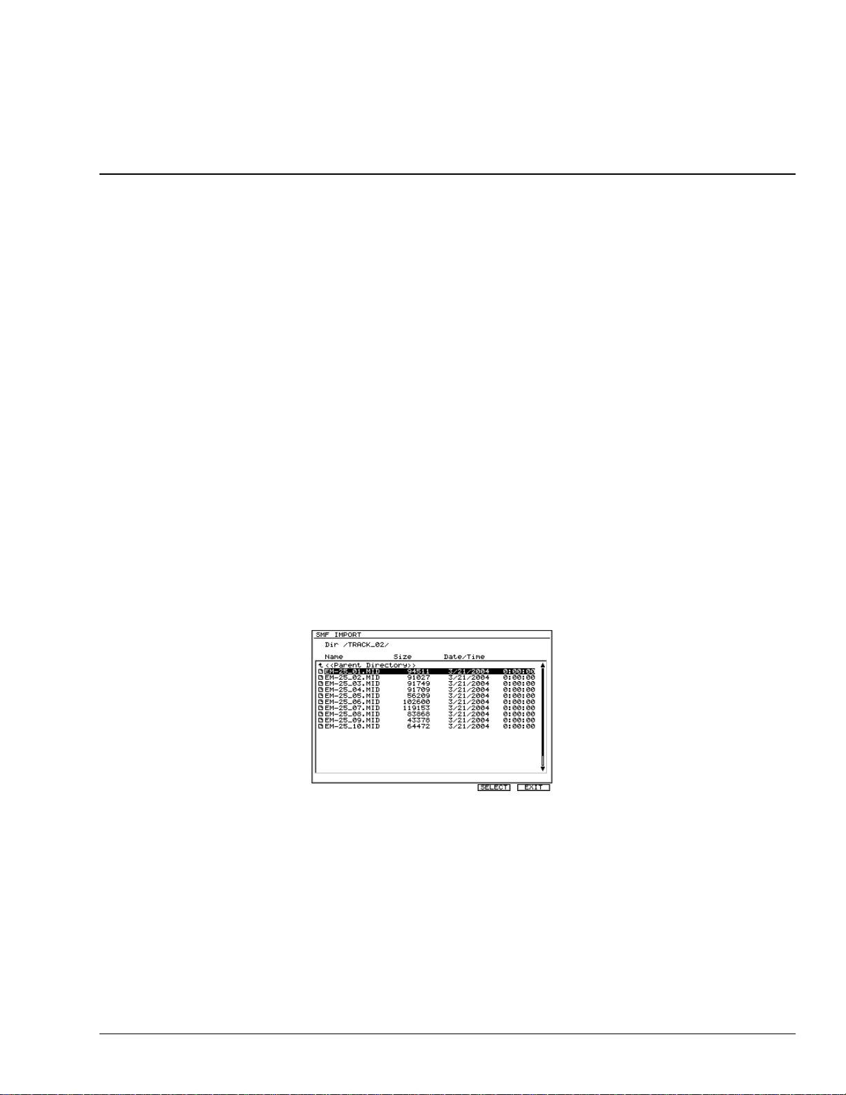
4. Press F3 (SMFImp)—the SMF IMPORT screen appears.
This screen presents you a list of all of the SMF and folders in the CD’s currently
selected directory. You can select any item in the list by using
Value dial to highlight it.
Each file directory on the CD appears in the displayed list as a folder. To open a folder,
select it and press F5 (ChgDir) for “Change Directory.” When you’re inside a folder, an
upward arrow points you bac k to the folder’ s parent directory. To move up and back out
of the folder, highlight “<<Parent Directry>>” and press F5 (ChgDir) again.
"
and
#
or the Time/
The list provides information about each of its SMF. This column can show you each file’s:
• Size —indicates the file size (in bytes).
• Date/Time —indicates the date and time at which the file was last modified.
Roland VS-2000 Owner’s Manual, Version Two Addendum www.RolandUS.com 9
Page 10
2—Version Two Enhancements
Importing rhythm patterns from SMF
The SMF data is imported into the current rhythm pattern. However, you need to
remember that the imported rhythm pattern is temporary. If you select another rhythm
pattern or turn off the power before saving the imported rhythm pattern, it will be lost.
If you want to keep a rh ythm pattern that y ou imported using the SMF Import function,
you must save it as a Project Rhythm Pattern or as a User Rhythm Pattern (Owner’s
Manual Page 319).
1. Insert a CD containing SMF data into your CD-R/RW drive.
2. Navigate to the RHYTHM PATTERN SETUP screen ( Owner’s Manual Page 314).
3. If “SMFImp” isn’t visible above F3, press the PAGE button so it is.
4. Press F3 (SMFImp).
5. Highlight the SMF you want to import.
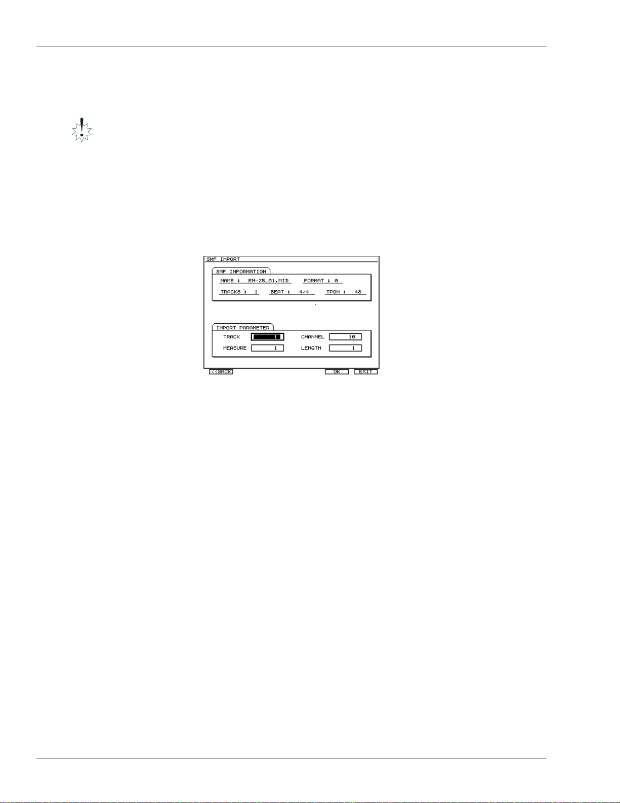
6. Press F5 (SELECT)—the SMF Import parameter screen appears.
To return to the SMF
IMPORT screen, press
F1 <<BACK). To abort
the procedure, press
F6 (EXIT).
In the SMF IMFORMATION area shows information about the SMF you selected
in the SMF IMPORT screen.
• NAME —file name
• FORMAT —SMF format. SMF Format 0 or Format 1 data can be imported.
• TRACKS —number of tracks
• BEAT —time signature
• TPQN (Ticks Per Quarter Note) —smallest unit of time in the SMF (the resolution
per quarter note)
7. In the IMPORT PARAMETER area, you can specify the data that will be imported
from the SMF as a rhythm pattern. Set the parameter to:
• TRACK —select the track that you want to import.
• CH ANNEL—select the channel that you want to import.
• MEASURE—specify the measure from which you want to start importing.
• LENGTH—specify the number of measures (length) that you want to import.
8. Press F5 (OK) to import the SMF into the current rhythm pattern.
9. When SMF import is completed, the Rhythm Pattern Setup screen appears.
10 www.Roland.com Roland VS-2000 Owner’s Manual, Version Two Addendum
Page 11
2—Version Two Enhancements
Backing Up and Recovering a project via USB
The following operations have been added. When connected with computer via USB,
you can:
• Backing up and Recovering VS-2000’s project
• Backing up and Recovering VS-2000’s user rhythm arrange or rhythm pattern
Important
You must carefully read “Caution when using USB Storage Mode” (Owner’s Manual
Page 81) together with this chapter, and perform this procedure as directed. Roland
Corporation accepts no responsibility for any loss of data or malfunction of the VS-2000
caused by incorrect operation. Nor will Roland accept responsibility for recov ering an y
lost hard disk content nor any damages that may result from such loss.
Data structure of the VS-2000’s internal hard disk
VS-2000 icons
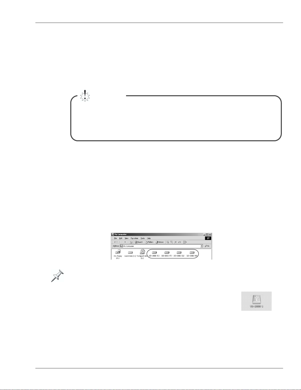
When USB Storage mode starts up and the internal hard disk of the VS-2000 has been
detected by your computer, one or more “VS-2000 icons” will appear.
Each VS-2000 corresponds to a partition. Up to four partitions (IDE:0–IDE:3) will be
detected in order of the partition number.
• Windows ME/2000/XP
The VS-2000 icon(s) will be added to “My Computer.”
[Example] Windows 2000
The drive letter (the alphabetical name of the drive) will depend on your computer
system.
• Mac OS 10.2 or later
The VS-2000 icon(s) will be added to the desktop.
Roland VS-2000 Owner’s Manual, Version Two Addendum www.RolandUS.com 11
Page 12
2—Version Two Enhancements
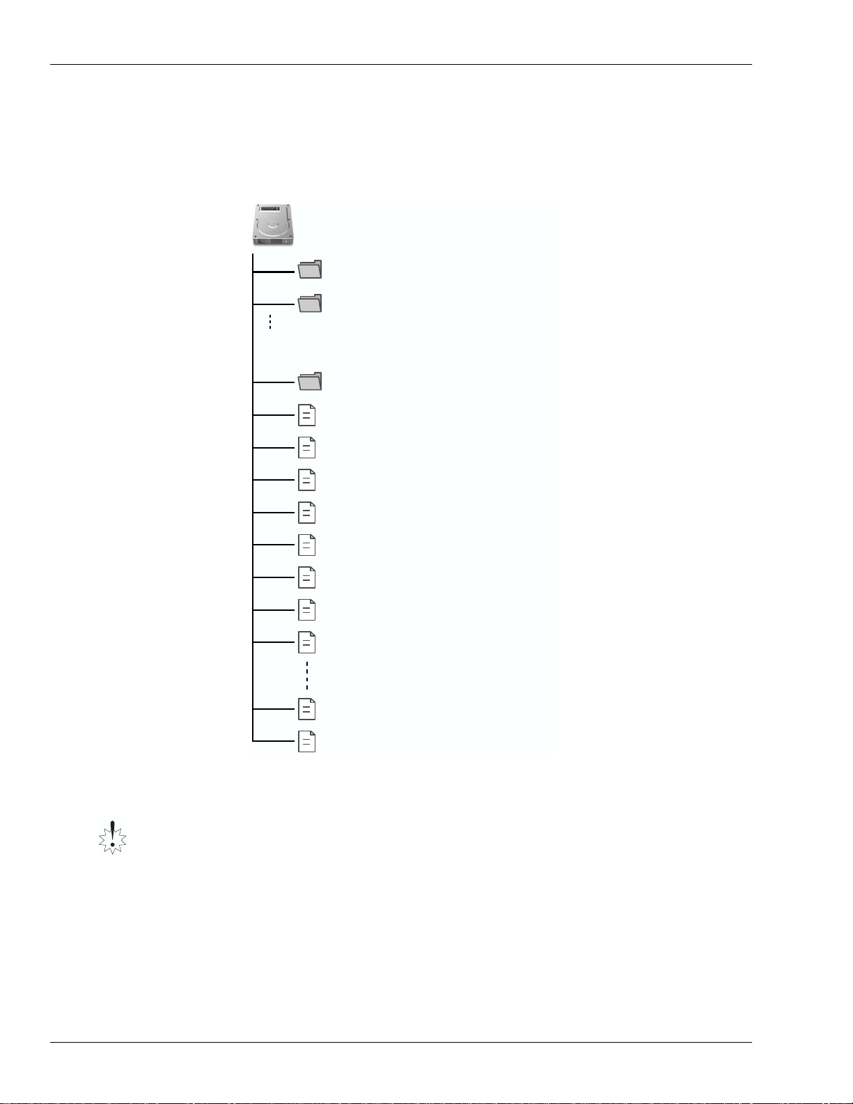
VS-2000 internal hard disk data structure
When you click a VS-2000 icon, the files and folders of the VS-2000’s internal hard disk
(partition) will be displayed on your computer.
These files and folders are organized as follows.
/ (root)
SONG0001.VS2
Project folder
SONG0002.VS2
Project folder
* A separate folder is created for each project.
PORT used to recover a data backed up
PORT
on your computer.
AMIXPCTL.VS2
Automix pattern data file
PRJRHARR.VS2
Project rhythm arrangement file
PRJRHPAT.VS2
Project rhythm pattern file
USRRHARR.VS2
User rhythm arrangement file
USRRHPAT.VS2
User rhythm pattern file
SONGLIST.VS2
Project list file
SYSTEM.VS2
System data file
TMPAMX0.VS2
Automix data 0 file
TMPAMX9.VS2
Automix data 9 file
TMPSCENE.VS2
Scene file
You can back up the following folders and files.
Never copy/move/rename/delete any folders or files other than those listed below.
Doing so will render the VS-2000 system unable to function correctly, and may also
result in the loss of your valuable data. Roland cannot guarantee that the VS-2000 will
operate if you manipulate any folders or files other than the following.
• SONGxxxx.VS2 folder —These folders contain the project data. You must back up the
entire folder.
• USRRHPAT.VS2 file —This is the user rhythm pattern data.
• USRRHARR.VS2 file —This is the user rhythm arrangement data.
12 www.Roland.com Roland VS-2000 Owner’s Manual, Version Two Addendum
Page 13
2—Version Two Enhancements
Backing up a project on your computer
You must not rename or rewrite the folders or files backed up to your computer. Doing
so will make it impossible to recover the data correctly.
1. Start up USB Storage Mode as described in “Establishing a connection to your
computer” ( Owner’s Manual Page 82). After a time, your computer will detect the
VS-2000’s internal hard disk.
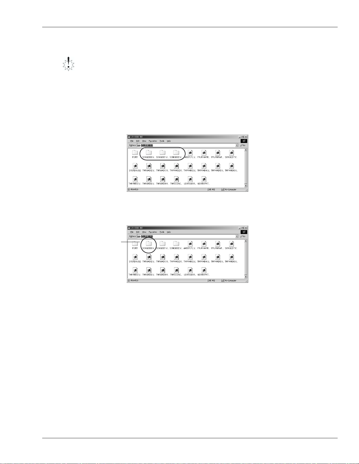
2. As described in “VS-2000 icons” on Page 11, double-click the VS-2000 icon for the
partition that contains the project you want to back up. The files and folders on the
VS-2000’s internal hard disk will be displayed.
[Example] Windows 2000
<< Project and folder names >>
The data for each project is
saved in a separate folder
named “SONGxxxx.VS2”.
The “xxxx” portion of the
folder name will be a number
in the order of the projects
shown in the project list.
3. Copy the entire folder “SONGxxxx.VS2” for the project you want to back up onto
the hard disk of your computer. The project data will be copied to your computer.
[Example] Windows 2000
Copy the entire
“SONGxxxx.VS2”
folder.
4. Exit USB Storage Mode as described in “Terminating the connection to your
computer” ( Owner’s Manual Page 84).
Roland VS-2000 Owner’s Manual, Version Two Addendum www.RolandUS.com 13
Page 14
2—Version Two Enhancements
Recovering a backed-up project from your computer
1. Start up USB Storage Mode as described in “Establishing a connection to your
computer” ( Owner’s Manual Page 82).
2. As described in “VS-2000 icons” on Page 11, double-click the “VS-2000 icon” for the
recovery-destination partition (i.e., the partition to whic h you will be reco vering the
project). The folders and files in the VS-2000’s internal hard disk will be displayed.
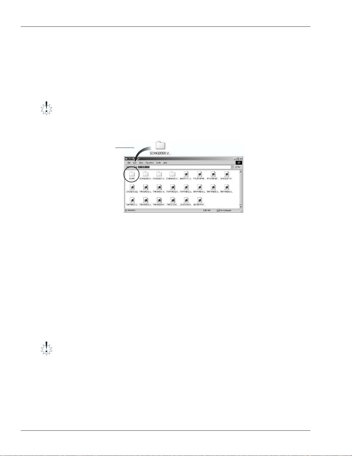
3. Copy the entire backed-up folder into the “PORT folder.”
Before copying the backed-up project into the “PORT folder,” you must disable the
“read-only” attribute from the folder and the files it contains.
The backed-up project will be recovered into the VS-2000’s internal hard disk.
[Example] Windows 2000
Copy the entire
backed-up
“SONGxxxx.VS2
folder” into the
“PORT folder.”
4. Exit USB Storage Mode as described in “Terminating the connection to your
computer” ( Owner’s Manual Page 84).
5. Access the Project List screen ( Owner’s Manual Page 99), and verify that the Recover
operation was successful. The recovered project will be added at the end of the
project list in the recover-destination partition.
Backing up and Recovering User Rhythm Arranges or Rhythm Patterns
You can back up and recover user rhythm arrangements and patterns in the same way
as when backing up and recovering a project. Simply bac k up and restore the follo wing
files.
• USRRHPAT.VS2 file (User rhythm patterns)
• USRRHARR.VS2 file (User rhythm arrangements)
User Rhythm Arrangement/Pattern data files are shared by all projects in the partition.
Be aware that when you recover these files, the existing user rhythm arrangement/
pattern data files will be overwritten.
14 www.Roland.com Roland VS-2000 Owner’s Manual, Version Two Addendum
Page 15
Added parameters and shortcuts
UTILITY Menu System Parameter
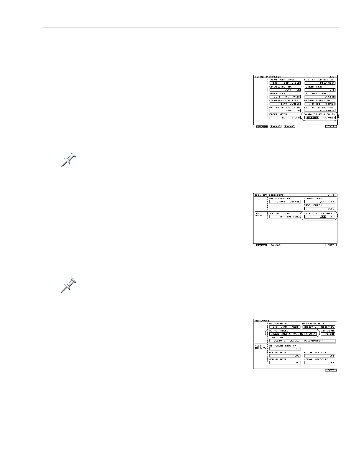
DYNAMICS/4Bnd EQ Sw parameter has been added
on the Param1 screen of the UTILITY menu’s System
parameter. This selects the screen that appears in the
LCD display when you press DYNAMICS or EQ. You
can set the parameter to:
• Dynm/EQ —the Dynamics or Equalizer screen for
the current channel appears.
• Ch VIEW —the Mixer View screen for the current
channel will appear.
In the VGA display, the Mixer View screen for the current channel is always displayed.
2—Version Two Enhancements
UTILITY Menu PlayRec Parameter
FX Rtn SOLO ENABLE parameter has been added on
the Param1 screen of the UTILITY menu’s PlayRec
parameter. This specifies solo setting of EX return
channels. You can set the parameter to:
• On —channel 1-6 of FX return will be automatically
soloed subject that solo of Input or Track channel is
turned on.
• Off —no channel of FX return will be automatically
soloed. Solo must be manually set selecting c hannel
of FX return.
This setting is valid if SOLO/MUTE TYPE PlayRec parameter is set to All BUS Send.
The METRONOME screen
OUTPUT SELECT parameter has been added on the
METRONOME screen ( Owner’s Manual Page 308).
When you set METRONOME OUT parameter to INT ,
this field selects the output jack(s) and a digital
connector from which the metronome sound will be
output. The metronome sound will be output from the
jack(s) whose check box is selected.
Roland VS-2000 Owner’s Manual, Version Two Addendum www.RolandUS.com 15
Page 16

2—Version Two Enhancements
The MASTER EDIT screen
Function button F4 (FX RTN) has been added (the LCD display only). Press F4 (FX RTN)
the FX return Parameter View screen ( Owner’s Manual Page 231). When this screen
appear, the FADER parameter is displayed as default.
CH PARAMETER LEVEL knob
You can use the CH PARAMETER Level knob to adjust the Ratio of the DYN parameter
(Owner’s Manual Page 167).
CH PARAMETER Knob: Expander parameter: Compressor parameter:
LEVEL knob Ratio Level
New Shortcuts
A variety of new shortcuts have been added in Version Two.
Hold down: To:
CLEAR and press CH EDIT switches the UTILITY menu’s Rtn TO Tr STATUS
Sw on/off parameter (Owner’s Manual Page 379).
CLEAR and
turn the TIME/VALUE dial
In addition, when the CH EDIT VIEW screen or the Parameter View screen is displayed:
Hold down: To:
CLEAR and
turn the TIME/VALUE dial
The mixer channel that is edited will be the mixer for the current channel. You will need
to select the parameters that will be affected.
When the CH EDIT VIEW screen or the Parameter
View screen is displayed, this edits the following
parameters for each mixer.
edits the following parameters for each mixer.
• Track Mixer—V-TRACK, MIX Switch, SOLO
Switch, MUTE Switch
• Input Mixer—MIX Switch, SOLO Switch,
MUTE Switch
• Effect return Mixer—MIX Switch, SOLO
Switch, MUTE Switch
16 www.Roland.com Roland VS-2000 Owner’s Manual, Version Two Addendum
Page 17
2—Version Two Enhancements
Change in editing method for Rhythm Arrange
The Rhythm Arrange editing method has been changed in VS-2000 system version 2.0.
The procedure described below replaces the section “Creating or Editing a Rhythm
Arrange” (Owner’s Manual Page 309).
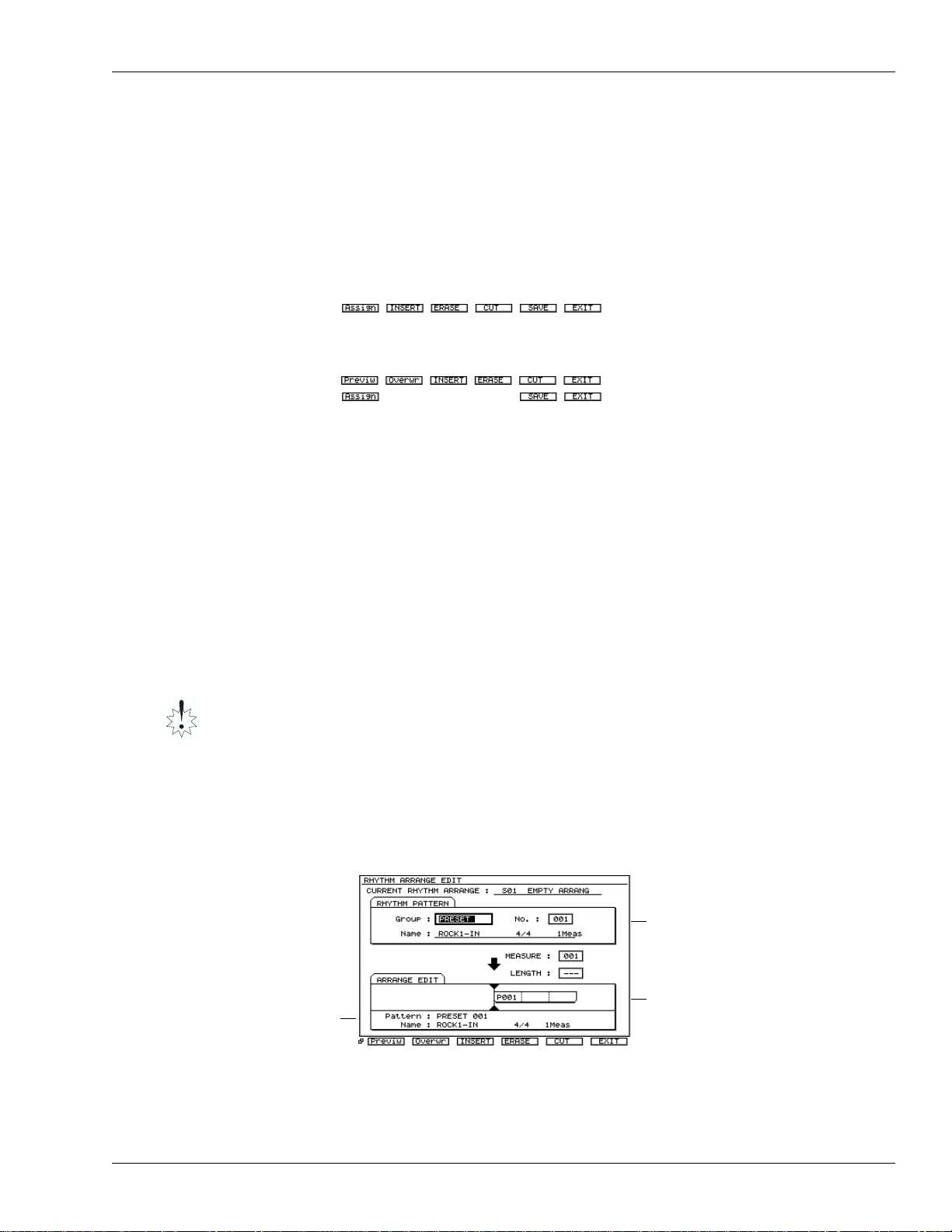
The F buttons in the RHYTHM ARRANGE EDIT screen have also been moved. The F
buttons have been moved as follows.
In Version One:
In Version Two:
If you’re looking for an screen
whose F button is currently
hidden, press PAGE repeatedly
until its F button appears.
Creating or Editing a Rhythm Arrange
Creating and editing a rhythm arrange are really the same process, since you always
start with the currently selected rhythm arrange.
Temporary Rhythm Arrange Memory
When you modify a rhythm arrange, it’s automatically copied into a special area of
temporary memory within the VS-2000. Any c hanges to make to the rh ythm arrange are
made to this copy . Its name changes to “TEMP” to show this. When y ou’re satisfied with
your work, save the rhythm arrange in the user or project Rhythm Track memory.
Once you begin editing an existing rhythm arrange, the VS-2000 holds it in a special
temporary memory area—the display shows “TEMP” at the front of the rhythm
arrange’s name. To avoid losing your work, save the rhythm arrange to user or project
memory before selecting a different rhythm arrange or turning off the VS-2000. See
“Saving a Rhythm Arrange” on Owner’s Manual Page 311.
1. Press RHYTHM TRACK to display the RHYTHM TRACK screen.
2. To create a new rhythm arrange from scratch, select USER 1—Empty Arrange.
Otherwise, select the rhythm arrange you wish to edit.
3. Press F2 (EDIT) to display the RHYTHM ARRANGE EDIT screen.
RHYTHM PATTERN
area
Information about
the rhythm pattern
assigned to the
current measure is
shown.
ARRANGE EDIT
area
4. If you’re creating a new rhythm arrange, press " to highlight MEASURE and turn
the Time/Value dial to Measure 1. If you’re editing a rhythm arrange, select a
measure whose rhythm pattern you wish to change.
Roland VS-2000 Owner’s Manual, Version Two Addendum www.RolandUS.com 17
Page 18
2—Version Two Enhancements
5. Press # to highlight the Group parameter and select the type of pattern you wish
to use at Measure 1.
6. Select the specific pattern you want to use by setting the No. value.
The selected rhythm pattern’s name appears beneath the Group and No.
parameters. To the right of its name is the pattern’s nominal length.
You can press F1 (Previw) to select rhythm pattern preview mode; the selected rhythm
pattern will play repeatedly. If “Previw” isn’t visible above F1, press the PAGE button so
it is. To exit preview mode, press F1 (Previw) once again.
7. You can selected one of two modes when you input Rhythm Pattern in the
ARRAGEN EDIT area. If “Overwr” or “INSERT” doesn’t appear above F2 or F3,
press the PAGE button once. Then press F2 (Overwr) or F3 (INSERT). Press:
• F2 (Overwr)—The rhythm pattern at the “MEASURE” location will be overwritten.
• F3 (INSERT)—The number of measures (length) of the selected rhythm pattern will
be inserted at the “MEASURE” location. The rhythm patterns assigned to
subsequent measures will not be overwritten.
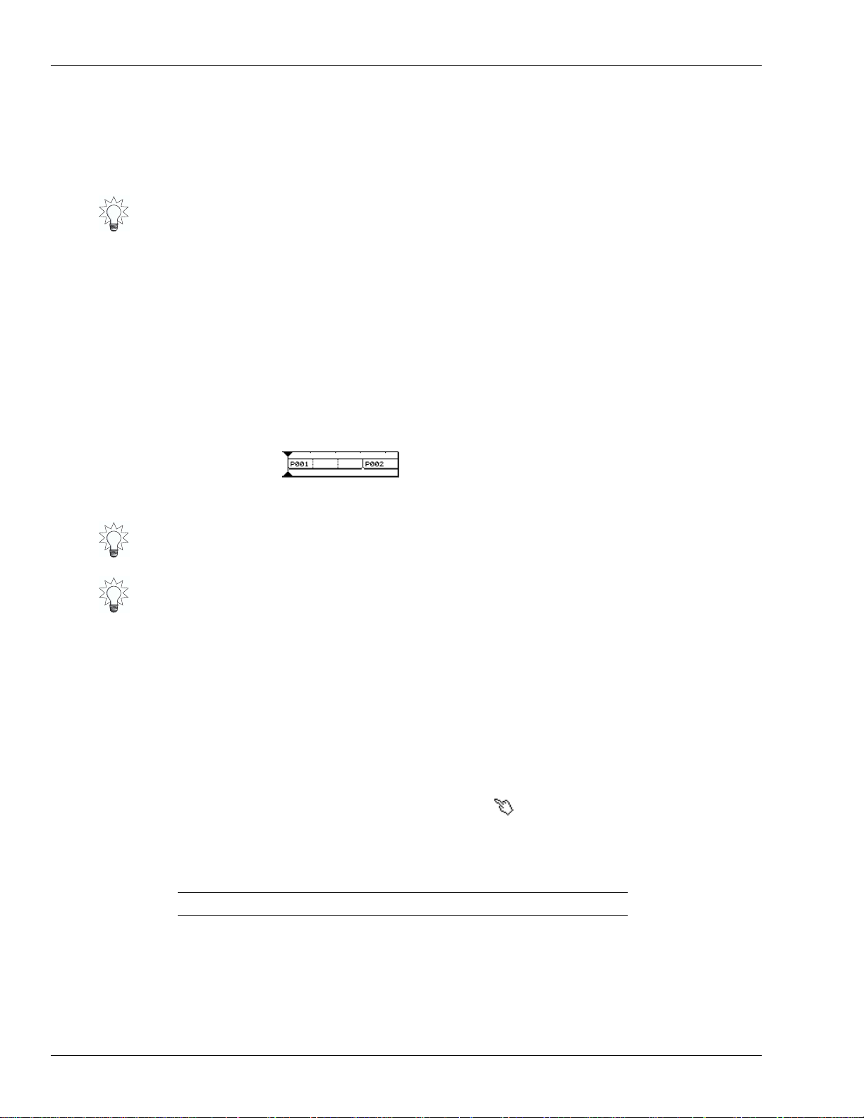
8. Adjust the LENGTH value as desired—as you do so, you see the pattern’s size change
to reflect the LENGTH value.
Pattern boxes
Box—Indicates the same rhythm pattern.
Dotted lines within box—Indicate locations at
which the rhythm pattern will repeat.
9. Set MEASURE to the next project section to set up, and repeat Steps 5-8.
Here’s a quick formula that tells y ou the next measure to be programmed when you’re
creating a new pattern from the top. Add the MEASURE value to the LENGTH value—
the total is the next measure you need to work on.
When you’re programming a rhythm arrange, you can increase the MEASURE value
using the FF button, or decrease it by pressing the REW button.
10. Repeat Step 9 until you’ve finished creating or editing the rhythm arrange.
11. Save you work before selecting a new rhythm arrange or turning off the VS-2000.
See “Saving a Rhythm Arrange” on Owner’s Manual Page 311.
Using the mouse to input a Rhythm Pattern
When step-recording a rhythm pattern (Owner’s Manual Page 317), you can use a
mouse to input drum sounds as follows.
In the pattern editing grid, move the mouse pointer to the desired drum sound and
input location so that the pointer changes to the “ ” shape, and click.
The velocity value of the drum note will change as follows each time you click.
using mouse: the velocity value changes:
Left-click None (blank) → 25 → 50 → 75 → 100 → 127
Right-click 127 → 100 → 75 → 50 → 25 → None (blank)
18 www.Roland.com Roland VS-2000 Owner’s Manual, Version Two Addendum
Page 19
2—Version Two Enhancements
The procedure for editing Harmony has changed
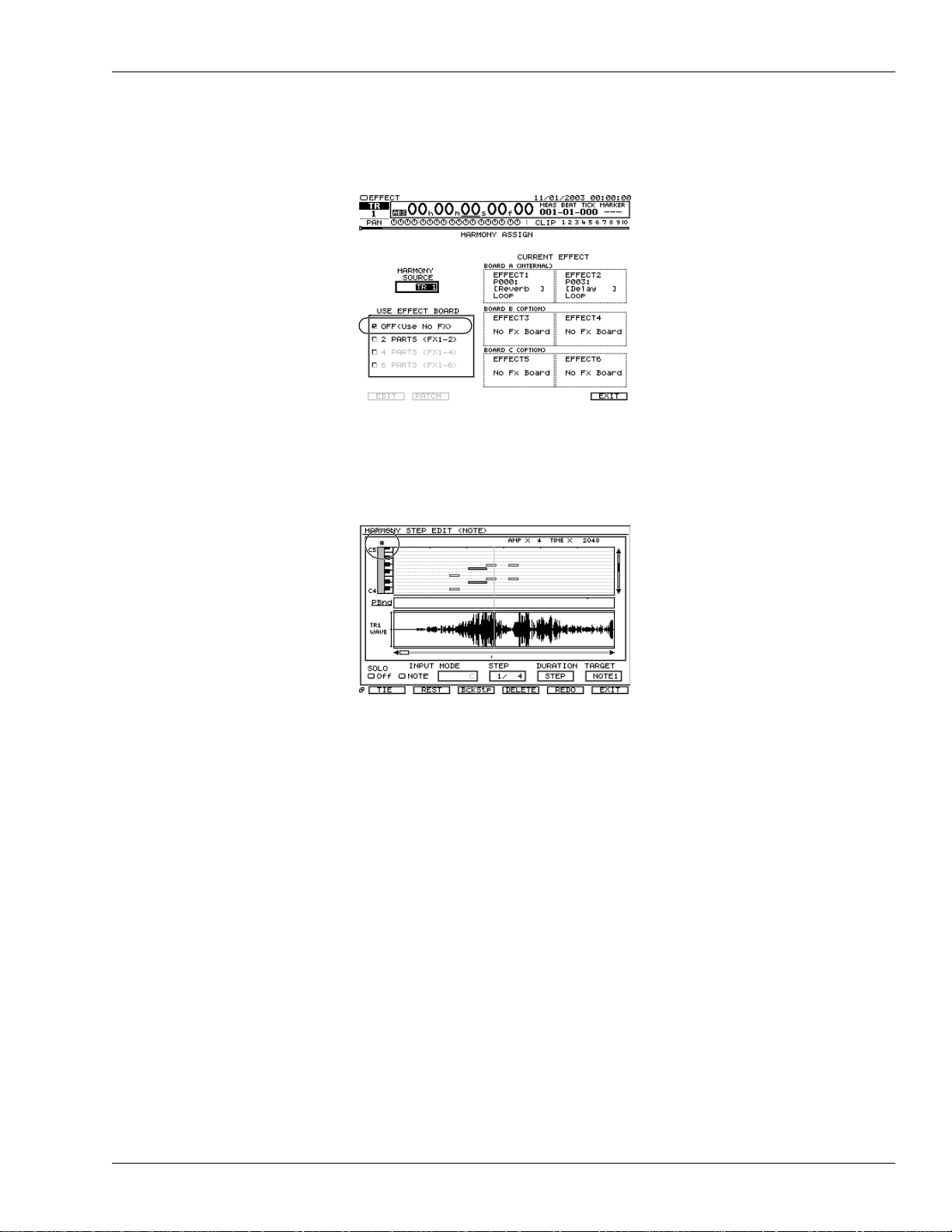
The HARMONY ASSIGN screen
OFF (Use No FX) can be selected under USE EFFECT BOARD parameter. You can
visually confirm whether harmony is turned on or off.
b/# indications have been added
If TRACK/STATUS button 12 (b/#) is pressed, “b” or “#” symbols are now displayed in
the HARMONY REALTIME RECORD screen and HARMONY STEP EDIT (NOTE)
screen.
Roland VS-2000 Owner’s Manual, Version Two Addendum www.RolandUS.com 19
Page 20
2—Version Two Enhancements
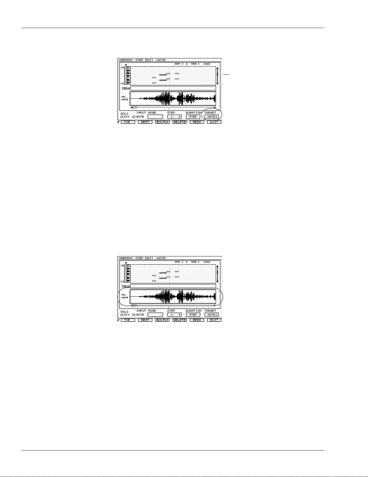
Sequencing Harmonies in Step Time
TARGET Parameter has been added
TARGET parameter has been added on the HARMONY STEP EDIT (NOTE) screen
(Owner’s Manual Page 339). You can now specify the harmony part and input note
events. You can select:
• NOTE—The harmony part is assigned automatically.
• NOTE 1–NOTE 6—Directly specify the harmony part 1–6. NOTE 1–NOTE 6
correspond to harmony parts 1–6.
Event list
New Event List Display
Note events (boxes) other than the harmony part specified by “TARGET” are displayed
in light gray.
Audio data waveform display
In the screens listed below, the WAVE area now always displays the audio data
waveform for the harmony source track. In conjunction with this change, the F button
F1 (WAVE) which switched the WAVE area waveform display on/off has been
eliminated.
• HARMONY REALTIME RECORD screen
• HARMONY STEP EDIT (NOTE) screen
• HARMONY MICRO EDIT screen
20 www.Roland.com Roland VS-2000 Owner’s Manual, Version Two Addendum
Page 21
2—Version Two Enhancements
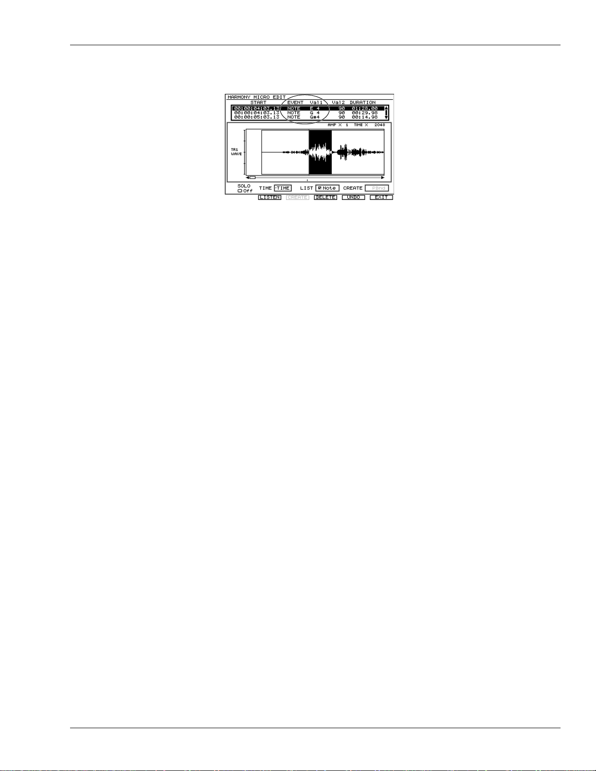
The HARMONY MICRO EDIT screen
EVENT: NOTE 1–NOTE 6 have been added
You can now specify the harmony part (1–6) of note events as follows:
• NOTE—The harmony part is assigned automatically.
• NOTE 1–NOTE 6—Directly specify the harmony part 1–6. NOTE 1–NOTE 6
correspond to harmony parts 1–6.
Val1: Note pitch editing
In the Harmony Micro Edit screen, you can now edit “Val1: pitch” of note events.
If editing “Val1: pitch” causes an overlap with an existing note event, a “Note event
overlaps! Overwrite?” dialog appears. Press ENTER/YES, the existing note event is
overwritten. To cancel, press EXIT/NO.
Roland VS-2000 Owner’s Manual, Version Two Addendum www.RolandUS.com 21
Page 22

2—Version Two Enhancements
22 www.Roland.com Roland VS-2000 Owner’s Manual, Version Two Addendum
Page 23
3—Version Two VGA Overview
The Main Display and the Info Display
Whenever an external VGA monitor is connected, the VS-2000 provides a main display
and an Info Display. The:
• main display—is where you work. You can interact with the main display using your
mouse, keyboard and the VS-2000’s top-panel controls. All messages appear here.
• Info Display—is a non-interactive screen that provides helpful supplemental
information. Page 26 describes how to determine the contents of the Info Display.
You can select the VGA display or the LCD display as the main display, but not both at
the same time. When you select the main display—by setting the OPERATION
TARGET parameter—the other display is automatically designated as the Info Display.
Setting the Operation Target
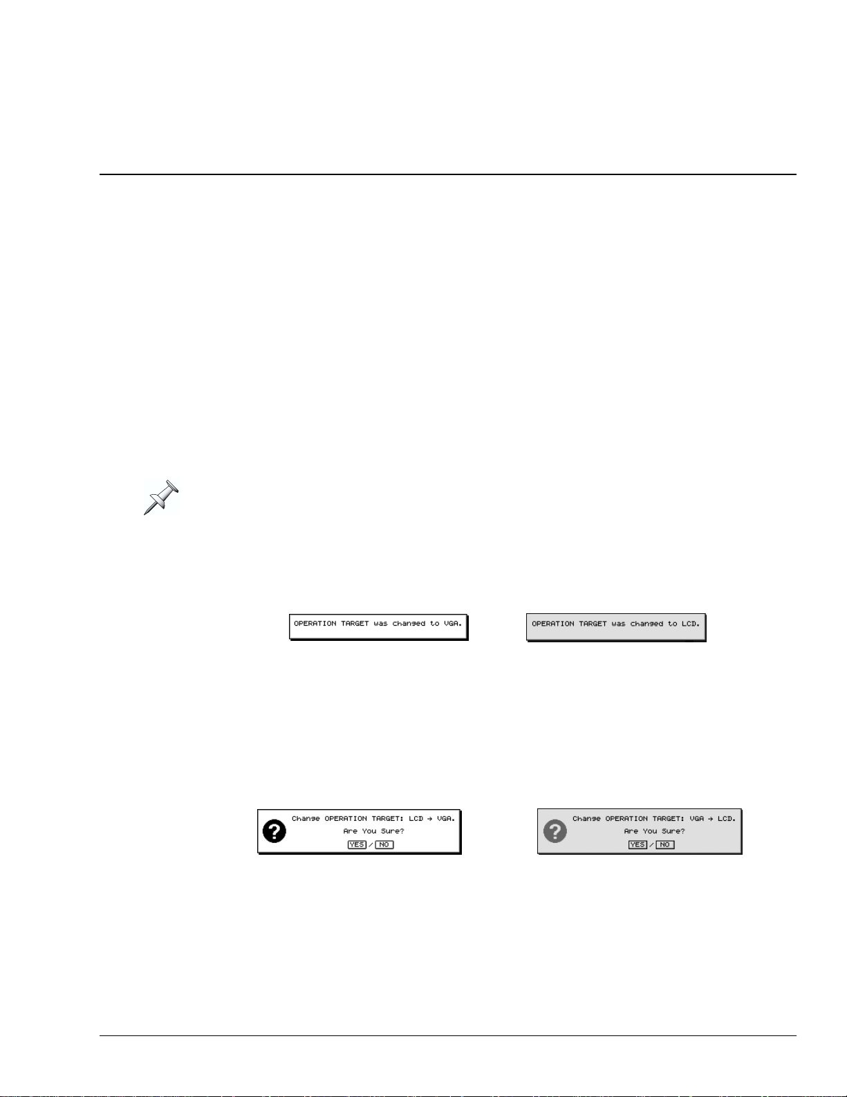
The VS-2000 displays the currently selected operation target when it powers up.
•You can toggle between the two OPERA TION TARGET settings—VGA or LCD—b y
holding down HOME and pressing the LCD↔VGA button. Each time y ou reset the
OPERATION TARGET, the previously selected main display confirms the change.
The internal LCD shows: The external VGA shows:
•You can manually set the OPERATION TARGET parameter as described below.
Manually Setting the OPERATION TARGET Parameter
1. Hold down SHIFT and press F4 (UTIL).
2. If “SYSTEM” isn’t visible above F1, press PAGE until it is.
3. Press F1 (SYSTEM).
4. Press F2 (Param3) and locate the OPERATION TARGET parameter.
5. Set OPERATION TARGET to VGA or LCD. On the main display, the VS-2000 asks:
or
6. Press ENTER/YES to proceed, or EXIT/NO to cancel the change.
Roland VS-2000 Owner’s Manual, Version Two Addendum www.RolandUS.com 23
Page 24
3—Version Two VGA Overview
About the Main Display
The LCD as Main Display
When the LCD is designated as the main display, it behaves as described in the VS-2000
Owner’s Manual.
The VGA as Main Display
With a connected external VGA display, your mouse and keyboard become your main
tools and the VS-2000 acts as a full-featured control surface. Its faders, knobs and
buttons provide a great way to physically interact with what’s on the VGA display:
•You can select channels and parameters on the VGA with your mouse, and change
their settings using the VS-2000’s faders or knobs if you wish.
•You can use the VS-2000’s transport buttons (Owner’s Manual Page 175) to operate
the hard disk recorder as you view your project on the VGA display.
•You can select audio or other data on the VGA using your mouse, and perform edits
instantly by pressing the appropriate button on the VS-2000. You can undo any edit
using the top panel’s UNDO•REDO button or its onscreen counterparts.
•You can use the VS-2000’s LCD as an secondary display on which you can keep
important information in view as you work on the VGA.
Of course, there’s no single “correct” way to use all of the VS-2000’s available tools—
odds are you’ll intuitively develop the easiest, fastest way to work for your needs.
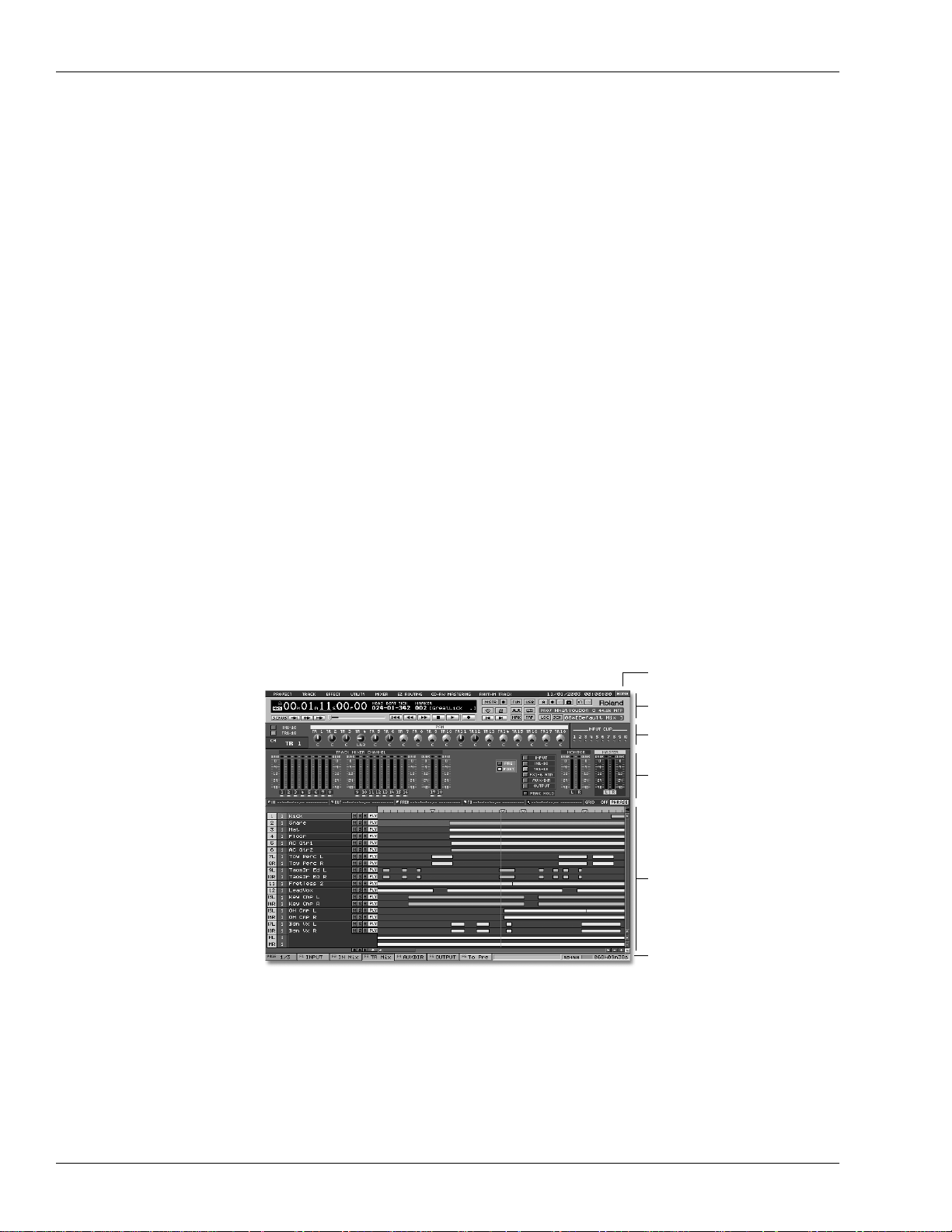
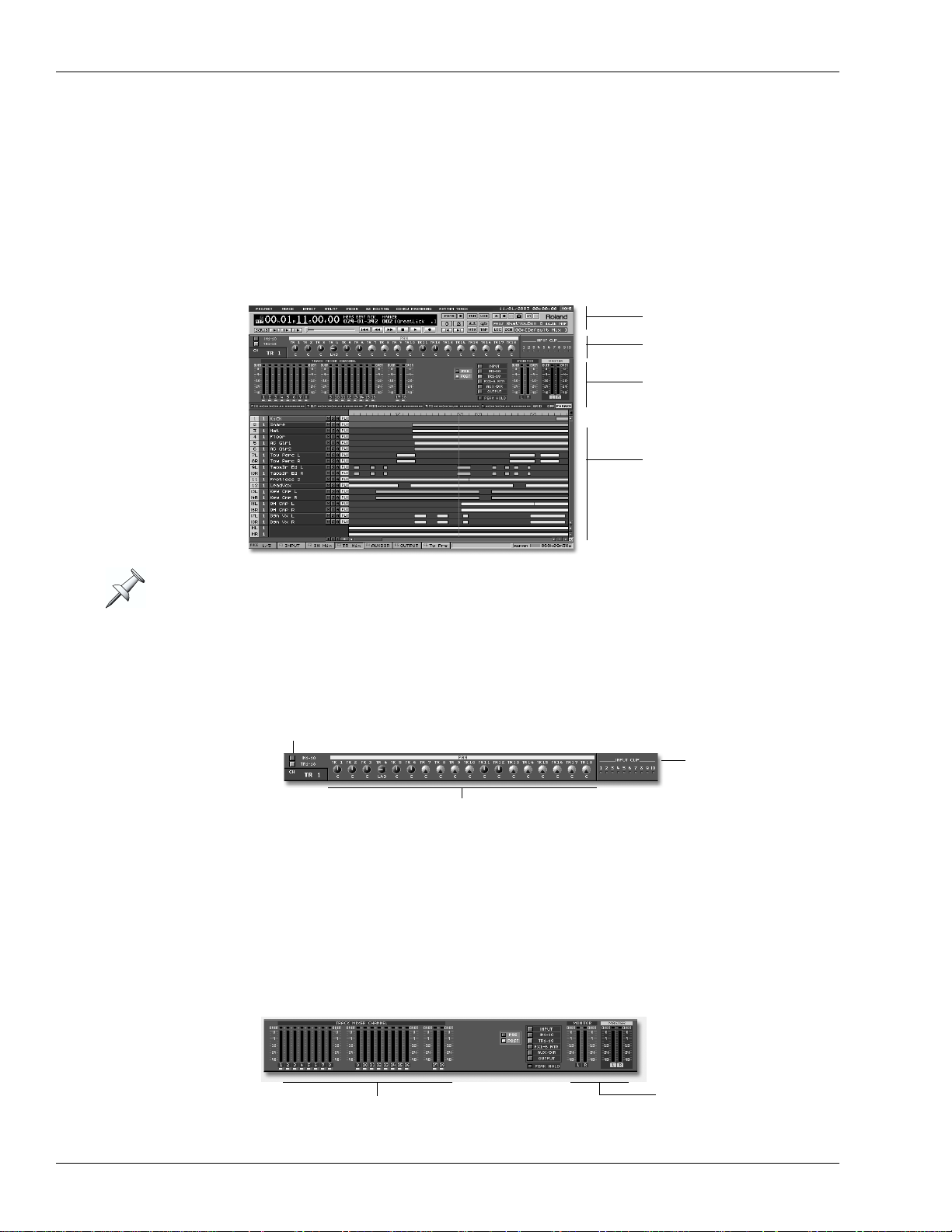
Areas of the VGA Main Display
When the VGA acts as the main display, it’s comprised of several different areas,
described in detail in the following chapters.
On the VGA main display Home screen—shown here—the lower
pane contains the project playlist, described in Chapter 5.
HOME button
Menus and control bar
PAN knob strip and
clipping indicators
Meters strip
Content pane
F buttons, status strip
and remaining space
status strip
24 www.Roland.com Roland VS-2000 Owner’s Manual, Version Two Addendum
Page 25
3—Version Two VGA Overview
Off
On
Off
On
Gray
Yellow
Gray
Red
Some of these areas are always available and some change, as described later in the
Addendum:
• Menus, control bar, F buttons, status strip and remaining space status strip—are always
visible on the VGA. See Chapter 4.
• PAN knob strip and clipping indicators—are always visible on the VGA. See Chapter 4.
• The meters strip—shows the currently selected level meters. See Chapter 5.
• Content pane—the contents of this area change as described in Chapters 5-8.
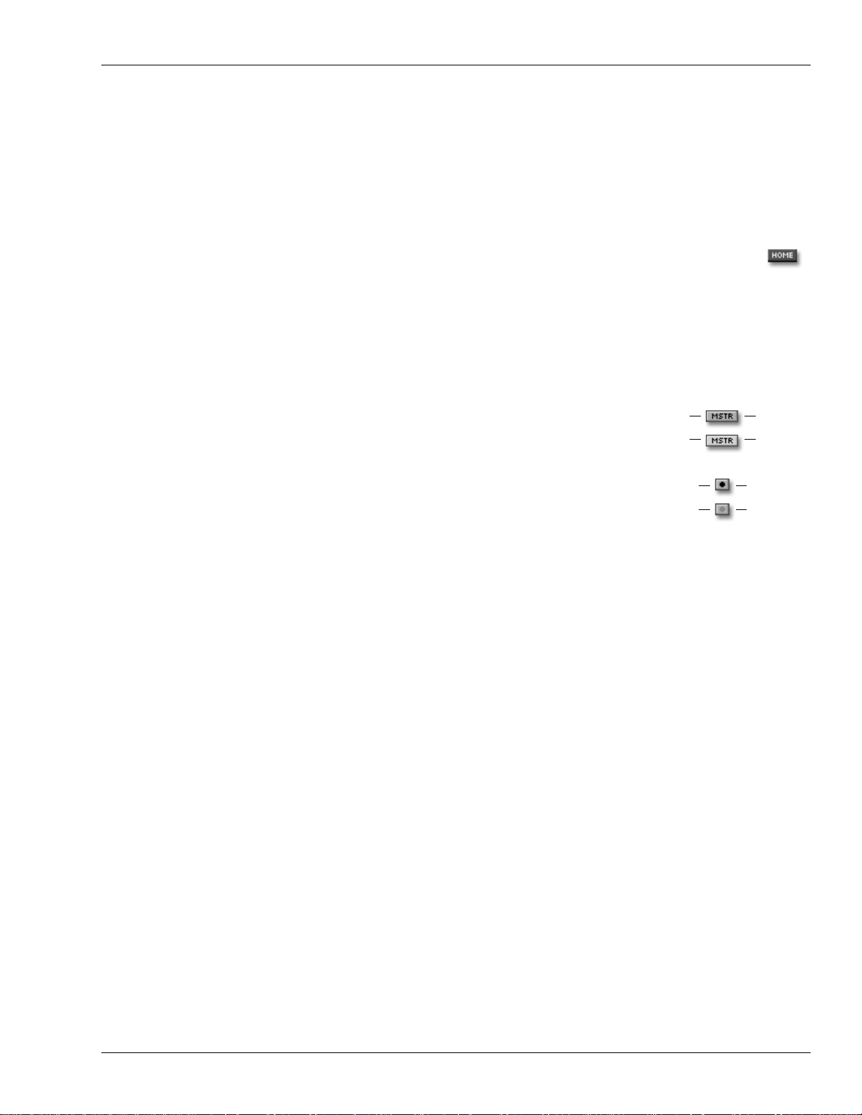
The VGA’s Main Display Home Screen
Like the LCD, the VGA main display has its own Home screen, shown on
the previous page. You can return to the Home screen at any time by
clicking the HOME button in the upper right-hand corner of the display (as
shown on Page 24), the HOME button on the VS-2000 or the Home button
on your keyboard.
Button Colors on the VGA Main Display
The VGA contains a wide assortment of on/off switches,
presented as clickable buttons. Unless otherwise noted,
when a button is switched on, it turns y ellow—when it’ s off,
it’s gray.
The transport REC button and the Mastering Room and
Automix Record buttons behave a little differently: they
turn red when activated.
Interaction with the VS-2000’s Top-Panel Controls
The VS-2000’s top-panel buttons generally interact with the currently selected main
display as described in the VS-2000 Owner’s Manual. When the VGA is selected as the
main display, however, there are a few minor differences:
• Hold down SHIFT and press F1 (PROJ), F2 (TRACK), F3 (EFFECT) or F4(UTIL)
button on the VS-2000 to display the corresponding menu on the VGA. To close a
menu, press EXIT/NO.
•The Home screen’s fader/pan buttons determine what’ s displa y ed in the lower part
of the screen. Press:
• IN F/P—to display the Input Mixer and Master Block.
• TR F/P—to display the Track Mixer and FX Return Mixer.
Sub-Windows
In some cases, when you click a button on the VGA main display or select a menu item,
a window opens that looks just like the corresponding screen on the VS-2000’s LCD,
with the same F buttons available at the bottom of the window. The contents of the
window behave the same way they do on the VS-2000’s LCD. You can exit the screen by
clicking the box in its upper-left corner or by pressing F6 (EXIT).
Roland VS-2000 Owner’s Manual, Version Two Addendum www.RolandUS.com 25
Page 26
3—Version Two VGA Overview
About the Info Display
You can choose what you’d like to see on the Info Display using the PAGE and F buttons
(see Owner’s Manual Pages 69 and 68). You can press these buttons on the VS-2000 or
click them on the VGA display.
When the VGA is Designated as the Info Display
Most of the VGA Info Display’s screens are divided into four areas.
VGA control bar
PAN knob strip
Meters strip
Bottom pane
The Info Display also provides a date and time readout in its upper right-hand corner.
VGA Control Bar
The VGA control bar is described in Chapter 4, starting on Page 35.
PAN Knob Strip
PAN select button
Clipping indicators
PAN knob settings
This strip shows the input or track channels’ current PAN settings. Click one of the
PAN select buttons at upper left of the trip, you can switch display of the PAN
parameter. To the right of the strip are input clipping indicators that show when a
channel’s input signal level is too loud.
Meters Strip
In certain display modes—see “Selecting Info Displays Manually” below—the meters
strip shows the set of meters currently selected on the Home screen.
Meters for the
MONITOR and
Currently selected meters
MASTER busses
26 www.Roland.com Roland VS-2000 Owner’s Manual, Version Two Addendum
Page 27
3—Version Two VGA Overview
Bottom Pane
The contents of the Info Display’s bottom pane changes from screen to screen.
Controlling What’s On the Info Display
As you navigate the VS-2000’s LCD display, the Info Display automatically switches
between various screens. You can manually switch to a few key screens, and you can
lock the display so that it doesn’t change as you move around on the VS-2000.
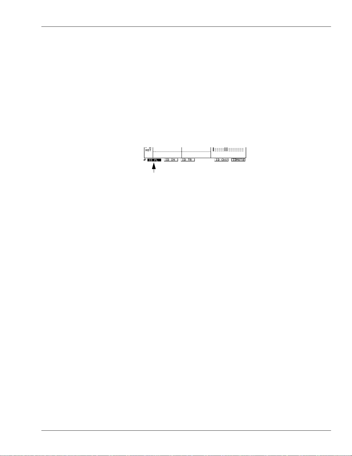
Selecting Info Displays Manually
You can access several key screens from the VS-2000’s Home screen.
1. Press HOME.
2. Press PAGE until “ID PL” appears above the F1 button.
3. You can press F1 through F5 to view the following screens:
• ID PL (Info Display Playlist screen)—shows the track playlist in the lower area on
the display.
• ID IN (Info Display Input Channels)—shows all 10 input channels in the lower
area on the display.
• ID TR (Info Display Track Channels)—shows all 18 track channels in the lower
area on the display.
• ID ChV (Info Display Channel View)—shows the CH EDIT parameters for the
currently selected input, track or FX return channel.
When the ID PL, ID IN or ID TR screens are in view, the meters strip is visible. You can
change what’s shown on the left side of the meters strip—the right side always shows
the MONITOR and MASTER output levels:
1. Press HOME.
2. Press PAGE until INPUT appears above F1.
3. Press:
• INPUT—to meter the VS-2000’s analog and digital input jacks and connectors.
• IN Mix—to meter input channel levels.
• TR Mix—to meter track channel levels.
• AUXDIR—to meter the AUX and DIR bus levels.
• OUTPUT—to meter the VS-2000’s output levels.
Locking the Info Display
You can lock the currently displayed Info Display screen so that it stays in view as you
move from screen to screen on the VS-2000 itself.
1. Press HOME.
2. Press PAGE until “IDHold” appears above the F6 button.
3. Press F6 (IDHold).
4. To unlock the display, repeat Steps 1-3.
Roland VS-2000 Owner’s Manual, Version Two Addendum www.RolandUS.com 27
Page 28

3—Version Two VGA Overview
When the LCD is Designated as the Info Display
To select what appears on the LCD Info Display:
1. Press HOME.
2. Press PAGE until “IDHome” appears above F1.
3. Press:
• F1 (IDHome)—to view the VGA display’s Home screen (Page 25).
• F2 (ID ChV)—to view the CD EDIT parameters for the currently selected input,
track or FX return channel (Owner’s Manual Page 149).
• F3 (IDWave)—to view the W a v e Displa y for the currently selected track (Owner’s
Manual Page 239).
• F6 (IDHold)—to lock the current contents of the LCD in place as you change
screens on the VGA display.
28 www.Roland.com Roland VS-2000 Owner’s Manual, Version Two Addendum
Page 29

4—VGA Main Display Universal Elements
This chapter describes the areas of the VGA main display that are always visible no
matter how the rest of the display changes. These are the:
• menus • control bar
•PAN knob strip • clipping indicators
•F buttons • status strip
• remaining space status strip
The illustration on Page 24 shows where these elements are located on the VGA.
VGA Menus
The menus at the top of the VGA display give you quick mouse access to all of the
features found in the VS-2000’s onboard menus, and also contain items unique to the
VGA main display. To select an item from a menu:
1. Click the desired menu with your mouse to display the
menu’s contents.
2. Move the cursor over the desired menu item to highlight it in
blue and click the item with your mouse.
An arrow to the right of a menu
item signifies additional choices presented in a
submenu. Hold you mouse cursor over the main menu
item, drag rightward and down to select the desired
item from the submenu and click your mouse.
To close a menu, click elsewhere on the screen or press EXIT/NO.
The PROJECT Menu
The PROJECT menu contains an assortment of options that relate to an
entire project.
Menu item: See Owner’s Manual Page:
NEW 102
RELOAD (See Addendum Page 30)
NAME 103
PROTECT 104
OPTIMIZE 105
SPLIT 107
EXPORT 113
PROJECT LIST 99
STORE (See Addendum Page 30)
SHUTDOWN 85
Roland VS-2000 Owner’s Manual, Version Two Addendum www.RolandUS.com 29
Page 30

4—VGA Main Display Universal Elements
Two PROJECT menu items are found only in the VGA display’s PROJECT menu:
• Select RELOAD to re-load the current project. This is a quick way get rid of any
actions you’ve performed since you last loaded the project.
• Select STORE to save e v erything you’ v e done to the current project since it w as last
saved or stored. This is the same thing as holding down SHIFT and pressing
ZERO•STORE on the VS-2000 itself, as described on Owner’s Manual Page 99.
The TRACK Menu
The TRACK menu provides access to phrase, region, take and wholetrack editing operations.
To learn more about what takes, phrases and tracks are, see Owner’s
Manual Page 94. To learn about phrase and region editing, see Owner’s
Manual Chapter 18.
Menu item: See Owner’s Manual Page:
REGION COPY 263
REGION MOVE 265
REGION INSERT 265
REGION CUT 266
REGION ERASE 267
REGION COMP/EXP. 267
REGION ARRANGE 270
TRACK IMPORT 269
TRACK EXCHANGE 270
TRACK NAME 272
PHRASE COPY 255
PHRASE MOVE 257
PHRASE TRIM IN 257
PHRASE TRIM OUT 258
PHRASE DELETE 258
PHRASE SPLIT 258
PHRASE NEW 259
PHRASE NORMALIZE 260
PHRASE DIVIDE 260
PHRASE NAME 261
TAKE MANAGER 262
The EFFECT Menu
The EFFECT menu provides quick access to tree types of screens:
• EFFECT VIEW—This screen presents a menu of your effect
processors, and provides basic information about each, as
described on Owner’s Manual Page 218.
30 www.Roland.com Roland VS-2000 Owner’s Manual, Version Two Addendum
Page 31

4—VGA Main Display Universal Elements
• EFFECT 1-6—display the Algorithm View screen for each processor (see Owner’s
Manual Page 219).
The EFFECT menu shows the available effect processors in your VS-2000, which depends
on how many optional VS8F-2 and/or VS8F-3 effect expansion boards are installed. As
shipped from the factory, the VS-2000 has two stereo effect processors, Effect 1 and Effect
2. With an optional VS8F-2 and/or VS-8F-3 installed, Effects 3 through 6 become available.
• HARMONY—The EFFECT menu also provides access to the operations associated
with the VS-2000’s top-panel HARMONY button. Select HARMONY, HARMONY
ASSIGN screen appears.
If “USE EFFECT BOARD” on HAYMONY ASSIGN screen is turned on, menu below
HAMONY can be selected.
Menu item: See Owner’s Manual Page:
HARMONY 327, (See Addendum Page 19)
ALGORITHM 328
PATCH SELECT 329
PATCH SAVE 331
STEP EDIT 338
REALTIME 337
MICRO EDIT 339
The UTILITY Menu
This menu provides access to the many parameters and features of the
VS-2000’s onboard UTILITY menu. The first six menu items display
groups of UTILITY menu parameter pages.
Menu item: See Owner’s Manual Page:
SYSTEM PARAMETER 378
DIGITAL I/O PARAMETER 382
DISPLAY PARAMETER 382
PLAY/REC PARAMETER 383
MIDI PARAMETER 283
SYNC PARAMETER 291
AUTO PUNCH/LOOP 191, 179
MARKER 188
LOCATOR 184
SCENE 144
RSS PAN SETUP 225
V-LINK SETUP 386
AUTOMIX SETUP 342
AUTOMIX EDIT (See Addendum Page 79)
DATE/TIME 67
PARAMETER INIT 385
Roland VS-2000 Owner’s Manual, Version Two Addendum www.RolandUS.com 31
Page 32

4—VGA Main Display Universal Elements
MIXER Menu
The MIXER menu allows you to display any of the VS-2000’s 40
mixer channels. You can do so in a variety of ways. To view:
• all of the parameters of a single:
• input channel—select it from the CH VIEW (INPUT) submenu.
• track channel—select it from the CH VIEW (TRACK) submenu.
• FX return channel—select it from the CH VIEW (FX RTN) submenu.
• the Aux and FX bus and Direct path configuration parameters—select MASTER EDIT.
• all of the input channels and MASTER EDIT parameters—select INPUT MIXER/
MASTER BLOCK.
• all of the track channels and FX returns—select TRACK MIXER/FX RTN MIXER.
For more information regarding the MIXER menu views, see Chapter 7, starting on
Page 69.
EZROUTING Menu
In the EZ ROUTING menu, select:
• ROUTING VIEW—to display the EZ ROUTING VIEW screen in which you can route
signals by dragging the desired connectors with your mouse. You can also turn
phantom power on and off and activate digital inputs. This screen is described in
detail in the Addendum’s Chapter 8 starting on Page 77.
• LOAD—to display the EZ ROUTING TEMPLATE LOAD screen, described on
Owner’s Manual Page 282.
• SAVE—to display the EZ ROUTING TEMPLATE SAVE screen, described on
Owner’s Manual Page 281.
CD-RW MASTERING Menu
The CD-RW MASTERING menu provides access to the operations
associated with the VS-2000’s top-panel CD-RW button.
Menu item: See Owner’s Manual Page:
MASTERING ROOM (See below)
CD-R WRITE 366
CD PLAYER 368
CD CAPTURE 374
WAVE IMPORT 369
TRACK EXPORT 372
PHRASE EXPORT 373
PLUG-IN INSTALL (See VS8F-3 Owner’s Manual)
PLUG-IN UNINSTALL (See VS8F-3 Owner’s Manual)
PLUG-IN BACKUP (See VS8F-3 Owner’s Manual)
32 www.Roland.com Roland VS-2000 Owner’s Manual, Version Two Addendum
Page 33

4—VGA Main Display Universal Elements
The Mastering Room
When you select MASTERING ROOM from the CD-RWMASTERING menu, the
Mastering Room (Owner’s Manual Page 359) replaces the meters strip.
EFFECT INSERT controls
Use the EFFECT INSERT matrix to insert effects on the MASTER bus.
Insert switches
and meters
In this illustration:
• FX 1 is already inserted on Input Channel 1, as its switch shows.
• only one optional VS8F-2 and/or VS8F-3 board is installed, so Effects 5 and 6 are
unavailable.
Insert matrix
• To activate an insert effect—click its switch so that it turns yellow and a blue box
showing its currently selected effect patch appears in the insert matrix. The matrix
shows how signal flows from one inserted effect processor to the next.
You’ll want to use one of the Mastering Tool Kit (MTK) effect patches. Select an oddnumbered processor since each powerful MTK patch requires an odd-numbered
processor as well as its even-numbered partner.
If a processor is unavailable because it’s already in use as an insert effect elsewhere, its
switch shows the name of the channel on which it’s inserted, as shown above.
If an even-numbered processor is being used by an MTK effect, it can’t be selected a
separate insert effect.
• To adjust the send to or return from an insert effect—drag
its blue insert send or return slider, respectively, up
Insert send slider
Insert return slider
or down to set the send or return level as desired.
• To select a new effect patch or edit the current patch—click on the effect’s blue box in the
matrix to display the processor’s Algorithm View screen (Owner’s Manual Page 219).
Roland VS-2000 Owner’s Manual, Version Two Addendum www.RolandUS.com 33
Page 34

4—VGA Main Display Universal Elements
RYHTHM TRACK Menu
The RYHTHM TRACK menu provides access to the operations
associated with the VS-2000’s top-panel RHYTHM TRACK button.
Menu item: See Owner’s Manual Page:
RYHTHM TRA CK 307
PATTERN SETUP 313
PATTERN SAVE 319
REALTIME REC 315
STEP REC/EDIT 317
SMF IMPORT (See Addendum Page 9)
ARRANGE EDIT (See Addendum Page 17)
BUTTON ASSINGN 310
RHYTHM BACKUP 322
RHYTHM RECOVER 322
METRONOME 308, (See Addendum Page 15)
TENPO MAP 296
34 www.Roland.com Roland VS-2000 Owner’s Manual, Version Two Addendum
Page 35

VGA Control Bar
104
130
359
The VGA main display’s control bar provides a wide assortment of important tools.
4—VGA Main Display Universal Elements
12.
1.
13. 14. 15. 16. 17. 18. 20. 22.
1. Write-protect indicator 13. SCRUB
2. Current Time Location display 14. PREVIEW buttons
3. Mastering Controls 15. Position bar
4. TUNER (TUN) 16. Transport buttons
5. USB storage 17. PREVIOUS/NEXT
6. Automix controls 18. MARKER
7. UNDO/REDO 19. TAP
8. EXT SYNC 20. LOCATOR (LOC)
9. Metronome 21. SCENE (SCN)
10. A.PUNCH 22. Scene name/number
11. LOOP 23. Project information
12. ABS/REL Indicator
2. 3. 6. 7.
8.
9. 10.11.
4. 5.
19. 21.
1. Write-Protect Indicator
When the current project is write-protected, the Write-Protect indicator
lights.
2. Current Time Location Display
23.
Measures, beats and tick locationTime code location
Most recent marker
Marker name/location
The Current Time Location display shows the current position of the
timeline in time code—hours/minutes/seconds/frames/subframes—
and in measures, beats and ticks. It also shows the most recent marker
and the marker’s name or—if it hasn’t been named—its time location.
You can navigate a project using the Current Time Location display, as described on
Owner’s Manual Page 131.
3. Mastering Controls
Master Tracks RecordMASTERING ROOM
Click MASTERING ROOM to turn the Mastering Room on or off. W hen
it’s on, click Master Tracks Record to start recording mastering tracks.
Roland VS-2000 Owner’s Manual, Version Two Addendum www.RolandUS.com 35
Page 36

4—VGA Main Display Universal Elements
4. TUNER (TUN)
Click TUNER to open the CHROMATIC TUNER window. You can use it
to make sure your instruments are precisely in tune.
5. USB storage
Click USB to open dialog to switch the system to USB storage mode.
6. Automix Controls
SNAPSHOTAUTOMIX
Automix Record Automix Undo/Redo
Click:
• AUTOMIX—to turn the Automix feature on or off.
• Automix Record—to start or stop recording Automix data.
• SNAPSHOT—to take a snapshot of your mixer settings at the
timeline’s current mixer location.
• Automix Undo/Redo—to undo or redo your most recent Automix
action.
7. UNDO/REDO
UNDO REDO
79
81
341
Click UNDO to reverse your last recording or editing action. If the
REDO light on the VS-2000 is lit, click REDO to restore your latest
undone action.
8. EXT SYNC
Click EXT SYNC so it lights to synchronize the VS-2000 to an external
device according to the current UTILITY menu Sync parameter settings.
9. Metronome
Off
INT
MIDI
Click the Metronome button to turn the VS-2000’s metronome on or
off by changing the setting of the METRONOME OUT parameter.
The parameter can be set to Off, INT (yellow) or MIDI (blue).
10. A.PUNCH
Click A.PUNCH to display the AUTO PUNCH/LOOP window in which
you can set punch in and -out points. If punch points have been set,
click this button turn on the VS-2000’s Auto Punch feature.
Punch-in and -out points appear above the Home screen’ s pla ylist as red arro ws. When
Auto Punch is turned on, a red bar connects the two points. See Page 50.
72
291
308
190
36 www.Roland.com Roland VS-2000 Owner’s Manual, Version Two Addendum
Page 37

4—VGA Main Display Universal Elements
178
300
181
180
126
175
11. LOOP
Click LOOP to display the AUTO PUNCH/LOOP window in which you
can set loop start and end points. If the loop points have been set, click
this button to turn on looped playback of the VS-2000’s hard disk
recorder.
Loop start and end points appear above the Home screen’s playlist as blue arrows.
When looping is turned on, a blue loop box connects the two points. See Page 50.
12. ABS/REL Indicator
The Current Time Location display can show absolute project time
(ABS), or can shift the time to correspond to an external device to whic h
the VS-2000 is being synchronized (REL).
13. SCRUB
Click SCRUB to repeatedly audition a tiny fragment of audio at the
timeline’s current location in order to pinpoint a recorded event.
14. PREVIEW Buttons
PREVIEW THRU
PREVIEW
TO
PREVIEW
FROM
When you’re trying to locate the precise time at which an audio event
occurs, click the appropriate PREVIEW button to listen to audio just
before and/or after the current position of the timeline.
15. Position Bar
Handle
Click and drag the position bar’s handle to move to any location in a
project. The position of the handle shows y ou where you are in a project.
16. Transport Buttons
Rewind STOP
RECZERO
FF PLAY
Click:
• ZERO—to return the timeline to the start of the project.
• Rewind—to move the timeline quickly back through the project.
• FF—to move the timeline quickly forward through the project.
• STOP—to halt playback of the project.
• PLAY—to begin playback from the timeline’s current location.
• REC—to begin recording.
Rewind and FF can
move the timeline in
increments as small as
one second.
Roland VS-2000 Owner’s Manual, Version Two Addendum www.RolandUS.com 37
Page 38

4—VGA Main Display Universal Elements
17. PREVIOUS/NEXT
NEXTPREVIOUS
Click PREVIOUS or NEXT to move the timeline backward to the most
recent phrase or marker, or forward to the next one, respectively.
18. MARKER (MRK)
Click MARKER to display the Locate to Marker window when y ou w ant
to move the timeline to the desired marker, or want to clear a marker.
Your project must contain at least one marker before you open the
Locate to Marker window.
19. TAP
Click TAP to place a new marker at the timeline’s current position.
20. LOCATOR (LOC)
Click LOCATOR to open the LOCATE window in which you can name,
clear, create, move or jump to locators.
21. SCENE (SCN)
Click SCENE to open the SCENE window in which you can name, store,
recall and configure scenes.
187
186
186
182
144
22. Scene Name/Number
This display shows the number—and if it’s been named—the name of
the last-recalled scene.
23. Project Information
Project name Project recording mode
Project sample rate
This readout shows the name of the current project, its sample rate and
its recording mode.
144
103, 102
38 www.Roland.com Roland VS-2000 Owner’s Manual, Version Two Addendum
Page 39

4—VGA Main Display Universal Elements
68, 69
PAN Knob Strip
PAN select button
Select channel
Click square buttons left side of IN1-10 or TR1-18, you can switch display of the PAN
parameter.
To “turn” a knob, click and drag up or down to raise or lower, respectively, its setting.
The VGA Input Clipping Indicators
The VGA main display’s input clipping indicators light when an input
channel’s analog input signal is too loud. The INPUT PEAK LEVEL
parameter sets the level at which they light—see Owner’s Manual Page
378.
VGA F Buttons
PAGE
The F buttons beneath the VGA main display’s content pane (Page 25)
mirror the current behavior of the F buttons beneath the VS-2000’s
internal LCD, as does its PAGE button. You can click the VGA’s F buttons
or the LCD’s at any time with the same results.
PAGE shows the number of screens associated with the current display.
You can move from page to page by pressing " and #.
If you prefer, press F1-F6 on a connected ASCII keyboard instead of clicking with your
mouse or pressing the VS-2000’s physical F buttons. Use Tab as your PAGE button.
F buttons
Roland VS-2000 Owner’s Manual, Version Two Addendum www.RolandUS.com 39
Page 40

4—VGA Main Display Universal Elements
Status Strip
The status strip contains flashing indicators that signal the activation of certain features
and modes that might not otherwise be visually obvious.
When: The status display flashes:
one or more channels are soloed “SOLO” in blue
one or more channels are muted “MUTE” in yellow
Mastering Room playback is turned on “MASTERING PLAY” in green
Mastering Room recording is turned on “MASTERING REC” in red
Automix recording is turned on “AUTOMIX REC” in red
VGA Remaining Space Status Strip
Remaining space gauge
Remaining space readout
The VGA Remaining Space strip shows you how much free hard disk
space remains on your internal hard drive. T he gauge graphically shows
the remaining space in bright green. You can select how the readout
shows the amount of free space left by setting the REMAIN DISPLAY
TYPE parameter.
380
40 www.Roland.com Roland VS-2000 Owner’s Manual, Version Two Addendum
Page 41

5—VGA Main Display Home Screen
Met
The VGA main display’s Home screen provides the basic starting point for VGA-based
VS-2000 operations. In addition to the universal elements described in the previous
chapter, the Home screen contains a selected set of meters that allow you to keep an
eye on various volume levels, and a project playlist in which you can perform a variety
of tasks, including the editing of track phrases and regions. This chapter describes how
the meters strip and the playlist areas work.
As we mentioned earlier, you can display the VGA Home screen in any of three ways:
• click the HOME button in the upper right-hand corner of the VGA display.
• press the HOME button on the VS-2000.
• press the Home key on a connected ACSII keyboard (Owner’s Manual Page 64, 72).
The Meters Strip
ers strip control buttons
PRE/POST buttons
The VGA main display meters strip provides a variety of meters that allow you to view:
• input levels—signals coming into the VS-2000’s input jacks and connectors.
• input channel levels—signals as they come into or exit the 10 input channels.
• track channel levels—signals as they come into or exit the 18 track channels.
TRACK STATUS buttons—
see below
Roland VS-2000 Owner’s Manual, Version Two Addendum www.RolandUS.com 41
Page 42

5—VGA Main Display Home Screen
• fx return channel levels—signals as they exit the VS-2000’s internal effect processors.
• Aux, FX and Direct path levels—the two Aux master six FX master, and eight Direct
paths.
• output levels—signals as they exit the VS-2000’s output jacks and connectors.
The number of active FX return channels depends on how many VS8F-2 effect
Expansion Boards or VS8F-3 Plug-in Expansion Boards are installed in your VS-2000.
See Owner’s Manual Page 55.
Track Channel Meters TRACK STATUS Buttons
You can click the small button beneath a track channel meter to set the
corresponding hard disk recorder track’s status—the button acts just like
a TRACK STATUS button on the VS-2000, described on Owner’s Manual
Page 176.
The MONITOR and MASTER Meters
The stereo MONITOR and MASTER bus output levels are
displayed at the right of the meters strip except when the input or
output meters are visible.
Working with the Meters Strip
Reading a Meter
Each meter in the meter strip contains a vertical stack
of segments that light to show the corresponding
signal’s level—the higher the stack, the louder the
signal. The segments are color -coded to help you see at
a glance how loud your signal is. If a signal exceeds
0dB, the meter’ s O VER indicator lights to show y ou that
the signal’s too loud.
OVER
indicator
Red
—indicates
that the signal is
approaching 0dB.
Yellow
—warns
that you’re
nearing the red
area.
Green
—shows
that signal is
present.
42 www.Roland.com Roland VS-2000 Owner’s Manual, Version Two Addendum
Page 43

5—VGA Main Display Home Screen
The TR 1-18
button is red to
indicate that the
track channel
meters are
being displayed.
Selecting the Desired Meters
The strip provides a set of meters for each of the signal types listed above. You can
select the meters you want to display in either of two ways. You can use the:
• meters strip control buttons—Click:
• INPUT—to display input signal levels.
• IN 1-10—to display input channel levels.
• TR 1-18—to display track channel levels.
• FX1-6 RTN—to display internal effect return levels.
• AUX/DIR—to display Aux bus and Direct path
levels.
• OUTPUT—to display output levels.
• PAGE and F buttons on the V GA or on the VS-2000—Press PA GE until “INPUT” appears
above F1 and press:
• INPUT—to display input signal levels.
• IN MIX—to display input channel levels
• TR MIX—to display track channel levels
• AUXDIR—to display Aux bus and Direct path levels.
• OUTPUT—to display output levels.
To display FX return levels using the F buttons, press PAGE until “FX RTN” appears
above F5 and then press F5 (FX RTN).
The meters strip on the VGA operates in much the same way as the LCD meters strip.
See Owner’s Manual Page 128 for additional info.
Pre and Post
You can select pre or post metering when you’ re viewing anything other than input and
output signals. (To learn about pre and post metering, see the note on Owner’s Manual
Page 125.)
Select the desired type of metering by:
• clicking the meters strip’s PRE or POST button.
• use the PAGE and F buttons on the VGA or VS-2000:
1. Press PAGE until “INPUT” appears above F1.
2. Click or press:
• F6 (To Pre)—to select pre metering.
• F6 (To Pst)—to select post metering.
The PEAK HOLD Button
PEAK HOLD button
Click the PEAK HOLD button so that it lights yellow to make your signals’ loudest
levels “stick” in their meters until you release them. T he Peak Hold feature helps ensure
that you don’t miss any unexpected level peaks should you look away from the meters.
To “un-stick” the meters, click the PEAK HOLD button again to unlight it.
Roland VS-2000 Owner’s Manual, Version Two Addendum www.RolandUS.com 43
Page 44

5—VGA Main Display Home Screen
1
The Playlist Area
.
4.
3.
2.
5.
1. Edit control strip 4. Playlist control panel switch
2. Track controls 5. Navigation and zoom buttons
3. Now line 6. WAVE DISPLAY button
5.
6.
The VGA’s Home screen contains a project playlist that performs the same tasks as the
internal LCD’s playlist, and more. You can view your project’s tracks, navigate the
project, place markers and edit track audio with your mouse in the VGA playlist. In
addition, you can mute and solo any track, set its Automix status, and adjust important
track channel CH EDIT parameters. You can also select V-Tracks and store and recall
locators and scenes right from the playlist.
To learn about: See Owner’s Manual page:
the project playlist 126
markers 186
editing track audio 235
Automix 341
CH EDIT parameters 147
locators 182
scenes 142
Operating the VGA Playlist
Getting Around
You can move through a project using the VGA playlist’s horizontal scroll bar and
buttons, located at the bottom edge of the playlist.
Scroll buttons
Scroll bar
44 www.Roland.com Roland VS-2000 Owner’s Manual, Version Two Addendum
Page 45

5—VGA Main Display Home Screen
Scroll
bar
Scroll
buttons
To move quickly through the project, drag the scroll bar in the
desired direction—the size of the scroll bar indicates how much
of the project is currently visible. To move backward by small
increments, click the left scroll button. To move slowly forward,
click the right scroll button.
You can also use the VS-2000’s standard navigation tools—
the Time/Value dial and current time location display as well
as locators, markers, and so on. (Project markers are shown
as gold downward-pointing triangles above the tracks in the
playlist, as shown on Page 50.)
Use the playlist’s vertical scroll bar and buttons along its
righthand edge to move up or down through the project’ s tracks.
To move quickly to a different set of tracks, drag the scroll bar in
the desired direction—the size of the scroll bar indicates how
many of the project’s tracks are currently visible. To move by
smaller increments up or down through the tracks, click the
desired vertical scroll button.
Zooming
The VGA playlist’s zoom buttons allow you to increase or
decrease the magnification of the project’s tracks. The:
• time zoom buttons—determine how much of the project is
displayed. Zoom in to view a smaller area more closel y, or
track zoom
buttons
out to view more of the project.
• track zoom buttons—determine how many tracks are
displayed. To show fewer tracks in greater detail, zoom in.
Time zoom
buttons
To show more tracks, zoom out.
Another way to zoom is to right-click on the pla ylist and select
the desired ZOOM item from the Edit Pop-Up menu (Owner’s
Track zoom
Manual Page 242). When you do, a window appears in which
you can select the desired magnification.
Time zoom
Track zoom Time zoom
You can also zoom in or out by holding down SHIFT and using the $, %, # or "
buttons on the VS-2000, as described on Owner’s Manual Page 127.
As you zoom in with the track zoom buttons, more onscreen space is available for each
track. As a result:
• additional track controls appear as space allows.
• when you zoom in so that only four or two tracks are visible, the VGA shows each
phrase’s waveform for editing purposes.
The VS-2000 generates editing waveforms when its transport is stopped—as a project
plays, these waveforms move across the now line. When the transport stops again, the
VS-2000 refreshes the playlist with new editing waveforms as necessary.
Roland VS-2000 Owner’s Manual, Version Two Addendum www.RolandUS.com 45
Page 46

5—VGA Main Display Home Screen
VGA Playlist Track Controls
2. 3.
6.
5.
4. 7.
1.
10. 11. 12. 13.
19.
1. Track number/CH VIEW button 11. ATT slider
2. V-Track selector 12. GROUP selector
3. Track name 13. LINK switch
4. MUTE button 14. FX Ins selector
5. SOLO button 15. DYNAMICS switch
6. AUTOMIX STATUS button 16. EQ switch
7. TRACK STATUS button 17. DIR 1-8 selector
8. FADER slider 18. MIX button
9. PAN slider 19. Aux and FX send controls
10. PHASE button 20. Status toggles
8.
15. 16.
20.
9.
17.
14.
18.
Each track in the playlist contains a track control area in which you can access the
corresponding track channel’s important CH EDIT parameters without leaving the
playlist. This makes it easy to quickly perform mix-related adjustments as you work
with track audio. As you zoom in on the tracks—see Page 45—the number of available
controls changes as space allows. The illustration above shows the controls that are
available when you’re zoomed in to a two-track view).
With eight tracks displayedWith four tracks displayed
With 12 tracks displayed With 20 tracks displayed
Most of the track controls are VGA versions of the standard CH EDIT track channel
parameters described in Owner’s Manual Chapter 11—a few parameters have been
combined to save onscreen space. Each track’s TRACK STATUS and AUTOMIX
STATUS and buttons can also be found among the track controls.
46 www.Roland.com Roland VS-2000 Owner’s Manual, Version Two Addendum
Page 47

5—VGA Main Display Home Screen
The currently
selected V-Track is
checkmarked.
141
142
343
176
1. Track Number/CH VIEW Button
You can click the track’s number to display its CH VIEW screen—see Page 57.
2. V-Track Selector
The V-Track selector performs the same job as the CH EDIT V-Trk
parameter. It shows the number of the track’s currently active
V-Track—click on the number to display a pop-up menu from
which you can select a different V-Track. The menu shows each
V-Track’s name and indicates with symbols the presence or
absence of recorded data on each V-Track, and shows whether the
V-Track is currently selected.
Selected, contains audio
Selected, contains no audio
Contains no audio, not selected
Contains audio, not selected
If you’ve recorded mastering tracks in CDR mode, an asterisk to the right of track
number indicates that V-Track uses the CD-R recording mode.
To learn about V-Tracks, see Owner’s Manual Page 95.
3. Track Name
4. MUTE (M) Button
Click MUTE—so that it turns yellow—to silence the track’ s audio. T o
un-mute the track, click MUTE again.
You can quickly un-mute all of your muted tracks by clicking the Mute status toggle
button. See Page 49.
5. SOLO (S) Button
Click SOLO so that it turns blue to isolate the track by silencing all
un-soloed tracks. To un-solo the track, click SOLO again.
You can quickly un-solo all of your soloed tracks by clicking the Solo status toggle
button. See Page 49.
6. AUTOMIX STATUS (A) Button
When Automix is turned on, you can set the status of the track’s
corresponding Automix track by repeatedly clicking the AUTOMIX
STATUS button.
You can simultaneously set the Automix status of all of your Automix tracks by
repeatedly clicking the Automix status toggle button. See Page 49.
Roland VS-2000 Owner’s Manual, Version Two Addendum www.RolandUS.com 47
7. TRACK STATUS Button
Click a TRACK STATUS button repeatedly to set its track’s status—
this is the same as pressing the corresponding physical TRACK
STATUS button on the VS-2000.
Page 48

5—VGA Main Display Home Screen
8. FADER (LEV) Slider
Drag the FADER slider to set the track channel’s CH EDIT FADER
parameter. The readout to the right of the slider shows the track
channel’s output level in dB.
9. PAN Slider
Adjust the track channel’s stereo position by dragging the PAN
slider as desired—the current pan position is shown to the right of
the slider. When you move the slider, you’re adjusting the track
channel’s CH EDIT PAN parameter value.
10. PHASE Button
152
155
Click “NRM” or INV” in the PHASE button to reverse the phase
polarity of the track channel’s signal.
11. ATT Slider
Set the ATT slider to adjust the level of the signal coming from the
hard disk recorder into the track channel. T he signal’ s level is sho wn
to the right of the slider.
12. GROUP (GRP) Selector
To assign the track channel to a fader group, click to the right of
“GRP” and select the desired fader group from the pop-up menu.
13. LINK Switch
LINK combines the CH EDIT ChLink and F .LINK parameters. Click
to the right of “LINK” and select the desired type of linking from the
pop-up menu or turn off linking.
14. FX Ins Selector
The numbers located right side of “FXINS” shows the status of effect
insertion. The number of effect currently inserted is highlighted. To turn
On/Off of the effect insertion or change insertion mode, Click number of
effect. You can select insertion mode or turn off on pop-up menu.
153
151
153
150, 154
215
15. DYNAMICS (DYN) Switch and Overview
Turn on the track channel’s dynamics processor by clic king the DYN
switch. The current dynamics shape is shown graphically next to the
switch—when the switch is on, the shape becomes blue.
You set up a channel’s dynamics processing by drawing the desired shape with your
mouse in the CH VIEW screen as described on Page 63.
151
16. EQ Switch and Overview
Turn on the track channel’s EQ by clicking the EQ switch. The
current EQ curve appears to the right of the switch—when the
switch is on, the curve turns blue.
You can set up a channel’ s EQ b y dra wing the desired curve with y our mouse in the CH
VIEW screen, as described on Page 63.
48 www.Roland.com Roland VS-2000 Owner’s Manual, Version Two Addendum
152
Page 49

17. DIR (DIRECT) 1-8 Selector
MUTE status toggle
TRACK STATUS
toggle
SOLO status toggle
AUTOMIX STATUS toggle
5—VGA Main Display Home Screen
To assign the track channel to a Direct path, click the desired Direct
path’s number so it lights.
18. MIX Button
Turn MIX on to send the track channel’s signal into the MASTER
bus, the main stereo mix. Turn it off to remove it from the mix.
19. AUX and FX Send Controls
AUX Send
Send level
FX Send
The AUX and FX send controls include the following parameters:
• Send level—drag a slider to set the track channel’s Aux and FX send level to the
corresponding Aux and FX bus (See Owner’s Manual Page 150). The send level appears
to the right of the slider in dB. When Aux and FX busses are linked, the evennumbered bus’s send control is replaced by a panning handle, described on Page 73.
• Send status—turns the Aux and FX send to each bus on or off. See Owner’s Manual
Page 150.
• Pre/post switch—sets the pre or post configuration of each Aux and FX bus. See
Owner’s Manual Page 89.
When you change an Aux and FX bus’s pre/post setting, you’re setting the pre/post
configuration of the Aux bus for any channel that’s using it, as described on Owner’s
Manual Page 150.
Pre/post switch
Send status
154
152
The color of each Aux bus’s and FX bus’s slider provides helpful information at a
glance. When a slider’s:
• blue—the send is turned on and the bus is set to Post.
• red—the send is turned on and the bus is set to Pre.
• gray—the send is turned off.
When odd/even A ux busses are linked, the e ven-numbered
bus’s slider is replaced by a panning handle, as described on Page 73.
20. Status Toggles
Beneath the track control areas are five status
toggle buttons. You can click each button to
toggle the setting of the entire column of
buttons directly above it.
Click this status toggle: To:
MUTE un-mute all currently muted tracks.
SOLO un-solo all currently soloed tracks.
AUTOMIX STATUS set the status of all Automix tracks to the same value.
TRACK STATUS set the TRACK STATUS of all tracks to the same value.
Roland VS-2000 Owner’s Manual, Version Two Addendum www.RolandUS.com 49
Page 50

5—VGA Main Display Home Screen
The Playlist’s Measure Bar
Just above the playlist is a gray strip called the “measure bar.” The lines in the bar show
the project measures as defined by the project tempo map (Owner’s Manual Page 296).
The time bar also contains markers, CD track markers, edit point flags, punch points
and loop points.
Marker
Gold Blue
Auto Punch Points Loop Points
Punch in Punch out Loop endLoop start
When Auto Punch is on, a red bar
connects the red punch points.
CD Track Marker
(Red) (Green)
IN OUT FROM TO
When looping is on, a blue loop box
connects the blue start and end points.
Edit Points
You can place any of these items at the desired locations using onscreen tools. To learn
how to place:
• markers—see “TAP” on Page 38.
• edit points—see Page 52.
• Auto Punch points—see Page 36.
• loop points—see Page 37.
You can:
• reposition an object in the measure bar—by moving your cursor over the object so the
cursor becomes a pointing finger, and then dragging to the desired new location.
• clear an object in the measure bar—holding down CLEAR on the VS-2000, positioning
the mouse cursor over the object until it turns into a pointing finger, and then
clicking the object.
The Measure Bar Pop-Up Menu
Use the measure bar pop-up menu to quickly place:
• edit points • Auto Punch IN or OUT points
• loop FROM or TO points • markers
• CD track markers
Right-click in the measure bar at the desired time location and select the object you
want from the measure bar pop-up menu.
To delete all markers and CD track markers from a project, select Clr All MARKER
from the measure bar pop-up menu.
50 www.Roland.com Roland VS-2000 Owner’s Manual, Version Two Addendum
Page 51

5—VGA Main Display Home Screen
Editing VGA Playlist Track Audio
Now linePosition line
Editing track audio on the VGA main displa y is v ery much lik e editing with your mouse
on the VS-2000’s internal LCD. To learn about editing audio with your mouse, see
Owner’s Manual Page 242.
The ways in which editing on the VGA differs from editing on the LCD are:
• All edits performed using your mouse on the VGA occur instantly, without dialog
windows, to make editing fast. You can, of course, undo or redo any edit.
•The SELECT PHRASE (Owner’s Manual Page 244) and SELECT TRACK (Owner’s
Manual Page 245) pop-up menus are available only on the LCD.
Selecting Tracks on the VGA
To select a track on the VGA main display, click anywhere on the track in the playlist.
When a track is selected, its background changes to a lighter shade of gray and its
number turns blue.
Blue
Selected
Not selected
Selecting Phrases and Regions on the VGA
The VS-2000 automatically assigns an alternating pattern of colors to the phrases in the
playlist to make them easy to distinguish from one another . When a phrase or region is
selected, it turns black and is outlined in its original color . Its editing w av eform changes
from black to the original color of the phrase.
Not selected
Selected
Roland VS-2000 Owner’s Manual, Version Two Addendum www.RolandUS.com 51
Page 52

5—VGA Main Display Home Screen
The Edit Control Strip
Above the playlist you’ll find the edit control strip, which contains basic editing tools.
IN area OUT area FROM area TO area Cursor GRID
IN, OUT, FROM and TO Areas
PHRASE/REGION
The IN, OUT, FROM and TO areas allow you to set edit
Button
Edit point location
points (Owner’s Manual Page 236), jump to them and
clear them. Each has a colored triangular button
matching its playlist flag and a readout with its current
position. T o:
The IN area
• Place an edit point—move the now line to the desired location and click the edit
point’s button.
• Change an edit point’s location—move the now line to the desired location and click
the edit point’s button.
• Move the now line to an edit point—hold down SHIFT on the VS-2000 and click the
edit point’s onscreen button.
• Clear an edit point—hold down CLEAR on the VS-2000 and click the edit point’s
onscreen button.
You can re-configure the behavior of the edit point buttons by setting the EDIT POINT
Sw TYPE parameter, as described on Owner’s Manual Page 238.
Cursor
The cursor readout shows the current location of the mouse cursor to help you make
edits precisely. The readout shows its position in time code and measures and beats.
GRID
Click GRID to display a pop-up menu from which you can activate the
desired editing grid (Owner’s Manual Page 247).
REGION/PHRASE Button
Click the REGION/PHRASE button to select the desired type of
track audio editing.
235
52 www.Roland.com Roland VS-2000 Owner’s Manual, Version Two Addendum
Page 53

5—VGA Main Display Home Screen
The VGA Playlist Control Panel
Click the Playlist Control button located at the
upper right just above the playlist to open the
playlist control panel. To close the playlist control
panel, click the Playlist Control button again.
You can also show or hide the playlist control panel by holding down SHIFT on the
VS-2000 and pressing its HOME button.
The V.Track control panel pane allows you to activate any V-Track by clicking on it.
Each track’s 16 V -Tracks are arranged
in a horizontal row. A symbol shows
each V-Track’s status.
Selected, contains audio
Selected, no audio
Not selected, no audio
Not selected, has audio
Any V-Track that’s selected for
editing flashes. Destination V-T racks
also flash, outlined in gray. See
Owner’s Manual Page 244 for
details.
Click the control panel’s LOCATOR tab to display the Locator pane.
Select locator banks
with these buttons.
Perform locator
actions by clicking
these buttons
In the Locator pane, you can quickly store, recall and clear locators right from the
playlist.
Use the Locator pane for locator operations. To:
• change locator banks—click the desired bank’s number.
• store a locator—move the now line to the desired location and click the number of an
unused locator position.
• recall a locator—click the locator’s number.
• clear a locator—hold down CLEAR on the VS-2000 and click the locator’s number.
To name a locator—or perform other locator operations—click the LOC buttons
(Page 38), respectively.
Roland VS-2000 Owner’s Manual, Version Two Addendum www.RolandUS.com 53
Page 54

5—VGA Main Display Home Screen
Click the control panel’s SCENE tab to display the Scene pane.
Select scene banks
with these buttons.
actions by clicking
Use the Scene pane for scene operations. To:
• change scene banks—click the desired bank’s number.
• store a scene—set up your mixer settings as desired and click the number of an
unused scene position.
• recall a scene—click the scene’s number.
• clear a scene—hold down CLEAR on the VS-2000 and click the scene’s number.
To name a scene—or perform other scene operations—click the SCN buttons (Page 38),
respectively.
Perform scene
these buttons
54 www.Roland.com Roland VS-2000 Owner’s Manual, Version Two Addendum
Page 55

5—VGA Main Display Home Screen
239
The VGA Wave Display
Click the WAVE DISPLAY button in the lower right-hand corner of
the playlist to open the wave display.
The VGA wave display allows you to view a single track’s audio with the maximum
amount of detail for precision editing operations.
Track name Phrase name Magnification
Track
number
Amplitude
zoom buttons
Time zoom
buttons
The currently selected track’s number appears at the left of the wave display. To view
other tracks, drag the vertical scroll bar up and down or clic k the desired vertical scroll
button. To move through the project, drag the horizontal scroll bar or click the
horizontal scroll buttons.
You can zoom in or out by clicking the wave display’s zoom buttons. To zoom:
• vertically—click the desired amplitude zoom button.
• horizontally—click the desired time zoom button.
You can also select the desired amplitude or time zoom
value from the Edit Pop-Up menu that appears when you
Amplitude zoom
right-click in the wave display.
Time zoom
Amplitude zoom Time zoom
The time zoom is measured in samples.
To close the wave display, click the WAVE DISPLAY button again.
Roland VS-2000 Owner’s Manual, Version Two Addendum www.RolandUS.com 55
Page 56

5—VGA Main Display Home Screen
56 www.Roland.com Roland VS-2000 Owner’s Manual, Version Two Addendum
Page 57

6—VGA Main Display CH VIEW Screens
You can control the signal flowing through any input, track or FX return channel on its
VGA main display CH VIEW screen.
Input and
track channel
elements
Aux send controls DIR 1-8
This illustration shows an input channel’s CH VIEW screen. The track
channel and FX return channel CH VIEW screens look slightly different.
To learn about the input and track channel CH EDIT parameters, see Owner’s Manual
Chapter 11. The FX return channels’ CH EDIT parameters are described in Owner’s
Manual Chapter 17.
FX send controls
Displaying CH EDIT Parameters on the VGA
You can display the desired CH VIEW screen by selecting it from
the MIXER menu. To view the CH VIEW screen for:
• an input channel—select the desired input channel from
the CH VIEW (INPUT) submenu.
• a track channel—select the desired track channel from the
CH VIEW (TRACK) submenu.
• an FX return channel—select the desired FX return
channel from the CH VIEW (FX RTN) submenu.
Input/output
control strip
You can also:
• press the desired input channel’s INPUT button on the VS-2000 to display an input
CH VIEW screen (see Owner’s Manual Page 147).
• press the desired track channel’ s TRACK/STATUS button on the VS-2000 to display
a track channel’s CH VIEW screen (see Owner’s Manual Page 147). This operation
works only in case CH EDIT button is lit.
• hold down the desired FX return channel’s FX button on the VS-2000 for few seconds
to display a FX return channel’s CH VIEW screen (see Owner’s Manual Page 227).
• view a track channel’s CH VIEW screen by clicking its track number in the VGA
main display’s Home screen.
Roland VS-2000 Owner’s Manual, Version Two Addendum www.RolandUS.com 57
Page 58

6—VGA Main Display CH VIEW Screens
Universal CH VIEW Elements
The CH VIEW screens for input, track and FX return channels differ slightly, though
they contain some common elements. The following section describes those elements.
Input/Output Control Strip
The input/output control strip appears on the right side of all
of the VGA CH VIEW screens. This strip presents parameters
that allow you to control the output of the channel strip, and
meter its input or output. The following section describes how
the strip works with a single unlinked channel. Page 59
discusses how the strip works with linked channels.
Meters and PRE/POST Buttons
The meters allow you to view the level of signal coming into
or going out of the channel. The PRE and POST buttons
determine the signal level to be display ed. T o view the lev el of
signal:
• coming into the channel—click PRE.
• going out of the channel—click POST.
The CH VIEW meters are presented in pairs. With input and track
channels, you can see the le vels for the odd/e ven pair of c hannels to
which the currently selected channel belongs—there’s a number
beneath each meter to show the channel signal it represents. With
the stereo FX return channels, the two meters show the left- and
right-side signal levels.
RSS PAN
button
Meters
and PRE/
POST
buttons
SOLO
MUTE
MIX
PAN
(RSS)
FADER
152, 230
SOLO Button
To isolate the channel’s signal by silencing all un-soloed channels,
click SOLO so it lights. To un-solo the channel, click SOLO again.
MUTE Button
To silence the channel’s signal, click MUTE so it lights. To un-mute
it, click the button again.
MIX Button
Click MIX so it lights to send the track channel’s signal into the
MASTER bus, the main stereo mix. Turn it off to remove the signal
from the mix.
PAN (RSS)/BAL Knob
Set the stereo placement of the channel’s output in the MASTER
stereo mix by dragging its PAN knob—or BAL knob in an FX return
channel—up or down.
Click square button on left of RSS PAN so it’s lit, the appearance of
the PAN parameter will be change. You can control the amount of
the channel’s signal being sent to the effect.
142
141
152, 230
155, 229
155
58 www.Roland.com Roland VS-2000 Owner’s Manual, Version Two Addendum
Page 59

6—VGA Main Display CH VIEW Screens
152, 230
FADER
Drag the fader up or down to set the channel’s output level. The
readout beneath the fader shows the channel’s output level in dB.
The Input/Output Strip in Linked Channels
When channels are linked, a special SUB DISP (“SUB DISPLAY”) button becomes
available at the bottom of the strip. You can control the two channels together or set
each channel’s panning and level individually by clicking SUB DISP so it lights.
When SUB DISP is off,
a single silver balance
knob sets the overall
stereo positioning of
the linked signals. The
fader controls operate
together to set their
combined level.
When SUB DISP is on,
individual PAN knobs
become available, and
each fader controls the
level of its channel.
SUB DISP button
AUX and FX Send Controls
SEND Knob
button
The CH VIEW screens contain AUX and FX send controls with which you can send the
signal from any input, track or FX return channel to any of the VS-2000’s two Aux and
six FX busses. To:
• control an Aux or FX send level by the CH PARAMETER SENDS knob (Owner’s
Manual Page 167)—click the SEND Knob button of desired bus so it lights.
• turn on the send to an Aux or FX bus—click the bus’s Send Status button so it lights.
• set an Aux or FX send level—drag the Aux bus’s Send Level knob up or down as
desired.
•change the pre/post configuration of an Aux or FX bus—click the PRE/POST switch
repeatedly to select PRE or POST.
When you change an Aux or FX bus’s pre/post setting, you’re changing its setting for
any channel that’s using it, as described on Owner’s Manual Page 151.
Send Status button
PRE/POST switch
Send level knob
Roland VS-2000 Owner’s Manual, Version Two Addendum www.RolandUS.com 59
Page 60

6—VGA Main Display CH VIEW Screens
DIR (DIRECT) 1-8 Selector
To assign an channel’s signal to one of the eight Direct paths, click
the desired path’s button in the DIR 1-8 selector.
Channel-Specific Parameter Strips
At the left side of each CH VIEW screen is a strip that contains parameters specific to
the selected type of channel.
Input Channel Parameter Strip
1. Channel Name
2. PHASE Button
Click PHASE—so it’s lit—to reverse the phase
polarity of the channel’s signal.
3. ATT Knob
To adjust the level of the input signal coming into
the input channel, drag the ATT knob up or down
as desired—the readout beneath the knob shows
the current amount of attenuation.
153
151
207
1.
2.
3.
4.
5.
6.
7.
7. GROUP Selector
To assign the input channel to a fader group, click
GROUP and select the desired fader group from
the pop-up menu.
153
5. CH LINK Button
To link the channel to its odd/even partner so that any changes
made to one channel affect both, click CH LINK to turn it on.
150
6. FDRLINK Button
Click FDRLINK—so it’s lit—to link the current c hannel’ s fader to its
odd/even partner so their levels can be set by moving either fader
while their other parameters remain independently controllable.
154
7. AUTOMIX STATUS Button
Click the AUTOMIX STATUS button to set the channel’s status
when Automix is turned on.
60 www.Roland.com Roland VS-2000 Owner’s Manual, Version Two Addendum
343
Page 61

Track Channel Parameter Strip
151
153
150
154
343
6—VGA Main Display CH VIEW Screens
1. Channel Name
2. STATUS Button
Click STATUS repeatedly to set the status of the
corresponding hard disk recorder track. This is the
same as clicking the track channel’s TRACK STATUS
176
button on the VS-2000.
3. V.TRACK Selector
To select a different V-Track, click V.TRACK and
select the desired V-Track from the pop-up menu,
149
described on Page 47.
4. PHASE Button
Click PHASE—so it’s lit—to reverse the phase
polarity of the channel’s signal.
153
5. ATT Knob
To adjust the level of the signal coming into the track channel from
the hard disk recorder, drag the ATT knob up or down as desired—
the readout beneath the knob shows the current amount of
attenuation.
1.
2.
3.
4.
5.
6.
7.
8.
9.
6. GROUP Selector
To assign the track channel to a fader group, click GROUP and
select the desired fader group from the pop-up menu.
7. CH LINK Button
To link the channel to its odd/even partner so that any changes
made to one channel affect both, click CH LINK to turn it on.
8. FDRLINK Button
Click FDRLINK—so it’s lit—to link the current c hannel’ s fader to its
odd/even partner so their levels can be set by moving either fader
while their other parameters remain independently controllable.
9. AUTOMIX STATUS Button
Click the AUT OMIX STATUS button repeatedly to set the c hannel’ s
status as desired when Automix mode is on.
Roland VS-2000 Owner’s Manual, Version Two Addendum www.RolandUS.com 61
Page 62

6—VGA Main Display CH VIEW Screens
FX Return Channel Parameter Strip
1. Channel Name
2. FX Bus ASSIGN
Each FX bus is routed to the input of its samenumbered effect processor.
228
3. GROUP Selector
To assign the channel to a fader group, click GROUP
and select the desired group from the pop-up menu.
228
4. MONO Switch
By default, the output of an effect processor is stereo.
To collapse its left and right sides to a mono signal,
228
click MONO so it lights.
5. FX LINK Button
To link the parameter of FX send, click FX LINK so it lights. W hen it’s lit,
parameters will be linked with add/even numbered partners.
6. AUTOMIX STATUS Button
229
1.
2.
3.
4.
5.
6.
Click the AUTOMIX STATUS button repeatedly to set the channel’s
status as desired when Automix mode is on.
343
62 www.Roland.com Roland VS-2000 Owner’s Manual, Version Two Addendum
Page 63

6—VGA Main Display CH VIEW Screens
Input and Track Channel CH VIEW Elements
Track/V-Track Info
Track and V-Track info for a standard input or track channel
Track and V-Track info for linked input or track channel
At the top edge of an input and track channel CH VIEW screen is information about the
corresponding hard disk recorder track and its V-Tracks. If you’re working with:
• an input channel—the screen shows information regarding the same-numbered
hard disk recorder track.
• a track channel—the screen shows information about its corresponding track.
If the channel is linked, you’ll see track info for both of the corresponding tracks.
Dynamics and EQ Controls
Interactive graphic displays
The symbols in
the V-Track area
are described on
Page 47.
For an introduction to
dynamics processing,
see
Parameters
Owner’s Manual
Page 156.
For an introduction to
EQ, see
Manual
Owner’s
Page 160.
Each input and track channel CH VIEW screen contains a dynamics processor and EQ
that can be set up by dragging your mouse in a graphic display, or manually.
Dynamics
1. 2.
4.
3.
5.
Compressor
parameters
Expander
parameters
Type-specific parameters
Roland VS-2000 Owner’s Manual, Version Two Addendum www.RolandUS.com 63
Page 64

6—VGA Main Display CH VIEW Screens
1. DYNAMICS On/Off Button
Turn the dynamics processor on or off by clicking this button—
when it’s blue, the processor is turned on.
2. RESET Button
Click RESET to return the dynamics processor to its factory default settings.
3. Interactive Dynamics Display
The interactive dynamics display lets you draw the shape of
your processing. Click and drag on any of the red triangles to
set the corresponding dynamics parameter.
Owner’s Manual Page 160 explains how to understand what you
see in the graphic dynamics display.
4. Dynamics Type Selector
Click the desired button to select the type of dynamics processing you
want to use.
5. IN/OUT/GR Meters
These meters show, respectively, the signal coming into the processor, going out of it,
and the amount of dynamics processing being applied.
Type-Specific Parameters
The type-specific parameters change according to the type of dynamics processing you
select. These parameters are described in Owner’s Manual Chapter 11.
Parameter: For compressor,
see Owner’s Manual Page:
KEY IN 159 159
RATIO 157 157
THRESHOLD 158 158
ATTACK 158 158
RELEASE 159 159
A.GAIN 158 not applicable
LEVEL 159 not applicable
see Owner’s Manual Page:
For expander,
64 www.Roland.com Roland VS-2000 Owner’s Manual, Version Two Addendum
Page 65

6—VGA Main Display CH VIEW Screens
EQ
1. 2.
3.
4.
1. EQ On/Off Button
Turn the channel EQ on or off by clicking this button—when it’s blue,
the EQ is on.
2. RESET Button
Click RESET to return the EQ parameters to their factory default settings.
3. Interactive EQ Display
Draw the desired EQ curve by clicking and dragging on any of the red triangles to set
the corresponding EQ band.
4. EQ Meters
The EQ meters show the lev el the signal as it comes into the channel EQ and as it lea ves
it.
EQ Parameters
The CH VIEW EQ parameters are described on Owner’s Manual Page 162.
Roland VS-2000 Owner’s Manual, Version Two Addendum www.RolandUS.com 65
Page 66

6—VGA Main Display CH VIEW Screens
I
d
EFFECT INSERT Controls
Processor
buttons
Insert effect matrix
Each input and track channel CH VIEW screen contains an EFFECT INSERT matrix in
which you can insert an available effect processor—or the left or right side of a
processor—into the channel’s signal flow. The insert effect matrix shows each effect
inserted on the channel, as well as the signal flowing from one insert effect to the next.
The number of each processor’s currently selected patch is shown in the matrix as well.
To insert an effect on a channel, click the desired processor
button repeatedly to select the type of insert routing you
want to use. To learn how each of the available routings
works, see Owner’s Manual Page 215.
Each available effect processor has its own
processor button—in this illustration, only
one optional VS8F-2 and/or VS8F-3 effect
expansion boards have been installed, so
Effects 5 and 6 aren’t available.
Ins InsL InsR InsS
If a processor is already inserted elsewhere, its
processor button displays where it’s being used.
To select or edit an insert effect for a processor, click the effect in the
insert effect matrix—the processor’s Algorithm View screen appears
on which you can select a new patch or edit the current patch.
You can adjust the send and return levels to the inserted effect
by dragging the blue insert send and return sliders—located
to the right of the processor button—up and/or down.
This effect processor’s
already being used by
Track Channel 1.
221
nsert sen
Insert return slider
66 www.Roland.com Roland VS-2000 Owner’s Manual, Version Two Addendum
Page 67

6—VGA Main Display CH VIEW Screens
FX Return Channel CH VIEW Elements
LOOP FX ASSIGN
Effect algorithm display
LOOP FX ASSIGN
LOOP FX ASSIGN displays the FX bus that carries signals to each of the VS-2000’s
internal effect processors.
Effect Algorithm Display
The effect algorithm display shows the effect patch being used by the effect processor
associated with the selected FX return channel. Clic k anywhere on the effect algorithm
display to view the processor’s Algorithm View screen on which you can select a
different patch or edit the current patch.
Roland VS-2000 Owner’s Manual, Version Two Addendum www.RolandUS.com 67
Page 68

6—VGA Main Display CH VIEW Screens
68 www.Roland.com Roland VS-2000 Owner’s Manual, Version Two Addendum
Page 69

7—Mixer Views
140
382
You can select any of the following views from the MIXER menu (Page 32):
• Input Mixer/Master Block—all of the input channels and the MASTER EDIT
parameters containing all of the Aux and FX bus and Direct path settings.
• Track Mixer/FX Return Mixer—all of the track channels and FX return channels.
Shared Elements
The Input Mixer/Master Block and Track Mixer/FX Return Mixer views share some
elements that we’ll describe before proceeding with descriptions of the two views.
Shared MASTER Fader Strip
The MASTER fader strip—located at the right edge of the screen—controls the stereo
MASTER bus (Owner’s Manual Page 140.)
1. MON (MONITOR) Balance Knob
Drag the MON (for “MONITOR”) balance knob up or down to shift the
MONITOR bus output leftward or rightward, respectively.
2. MON Level Knob (Info Only)
The MON (for “MONITOR”) knob shows the level of the MONITOR bus.
This level can be adjusted only using the VS-2000’s MONITOR knob.
3. AUTOMIX STATUS (A) Button
Click the AUT OMIX ST A TUS button to set the MASTER
fader’s Automix status when Automix is turned on.
343
4. MASTER Bus Balance
Drag the MASTER balance knob up or down to shift the MASTER bus
output leftward or rightward, respectively.
5. MASTER Bus Fader
Drag the MASTER bus fader up or down to set the level of the MASTER
bus. The current MASTER bus level is shown beneath the fader.
1.
2.
3.
4.
5.
6.
6. DITHER (D) Button
To activate output dithering, click and hold the DITHER button, and
select the desired dithering bit depth.
Roland VS-2000 Owner’s Manual, Version Two Addendum www.RolandUS.com 69
Page 70

7—Mixer Views
AUX and FX Send Sliders
In the Input Mixer/Master Block and Track Mixer/FX Return Mixer, input, track and FX
return channels all sport Aux and FX send sliders. These sliders allow you to send the
desired amount of a channel’s signal to an y of the tw o A ux and six FX busses, and show
you at a glance each send level. To set an Aux and FX send level, click and drag its slider
with your mouse to the desired position.
A slider’s color provides information about its
Aux send. When a slider is:
• blue—the Aux send is on and set to Post.
• red—the Aux send is on and set to Pre.
• gray—the Aux send is turned off.
AUX Send
FX Send
Blue=On, Pst
Red=On, Pre
Black=No level
Gray=Off
• black—the send is turned all the way down.
You can change the Aux and FX bus’s pre/post setting:
• on any channel’s VGA CH VIEW screen (Page 59).
• in the Input Mixer/Master Block view (described on Page 71).
• in the MASTER EDIT window available in the VGA main display’s MIXER menu
(Page 32).
• in the track controls area in the playlist (Page 46).
When an odd/even pair of Aux and FX busses is linked, the slider for the even bus is
replaced by a panning handle, as described on Page 73.
70 www.Roland.com Roland VS-2000 Owner’s Manual, Version Two Addendum
Page 71

Input Mixer/Master Block View
151
141
142
Select INPUT MIXER/MASTER BLOCK from the MIXER menu to view all of the
VS-2000’s 10 input channel strips and MASTER BLOCK settings at once on the VGA.
7—Mixer Views
Master BlockInput Mixer
Input Channel Strips
1. DYNAMICS (DYN) On/Off
Click this button to turn the channel’s dynamics processor on—so the
button’s lit—or off. See Page 63.
2. EQ On/Off
To turn the channel’s EQ on or off, click this button. When it’s lit, the
EQ’s on. See Page 63.
3. AUX and FX Send Sliders
AUX Send
FX Send
Set the amount of the channel’s signal sent to an Aux and FX bus by
adjusting the corresponding Aux and FX send slider. With linked Aux
and/or FX busses, a panning handle replaces the even-numbered Aux
and/or FX bus’s slider (Page 73).
4. MUTE (M) Button
4.
6.
1.
2.
3.
5.
7.
8.
9.
To mute the channel, click this button so it’s lit. To un-mute the channel,
click the button again.
5. SOLO (S) Button
To solo the channel, click the SOLO button to light it. To un-solo the
channel, click the button again.
Roland VS-2000 Owner’s Manual, Version Two Addendum www.RolandUS.com 71
Page 72

7—Mixer Views
6. AUTOMIX STATUS (A) Button
When Automix is turned on, repeatedly click the AUTOMIX STATUS
button to set the channel’s Automix status.
7. PAN Knob
Set the stereo position of the channel in the main MASTER bus mix by
dragging the PAN knob up or down as desired.
8. Channel Fader
The position of the channel fader sets the level of signal coming out of
the channel. The channel’s level is displayed below the fader.
9. LINK Switch
LINK combines the CH EDIT ChLink and F .LINK parameters. Click
to the right of “LINK” and select the desired type of linking from the
pop-up menu, or turn off linking. The LINK switch occupies the
combined lower edge of both of the channels it controls.
Master Block Strips
The Master Block strips contain Direct path parameters (Owner’s Manual Page 208) and
Aux and FX bus control (Owner’s Manual Page 203).
343
155
152
150, 154
Direct path Parameters
1. Source
Click Source and choose the signal you want to assign to the Direct path.
2. Pre/Post Switch
This sets the Direct path to receive a channel’s signal before or after the channel fader.
3. AUTOMIX STATUS (A) Button
When Automix is on, repeatedly click this button to set the Direct path’ Automix status.
4. Final Level Knob
Drag this knob up or down to set the final level of the Direct path.
1.
2.
3.
4.
72 www.Roland.com Roland VS-2000 Owner’s Manual, Version Two Addendum
Page 73

7—Mixer Views
Aux and FX Bus Parameters
1. PRE/POST Switch
Click the PRE/PST switch to configure the Aux and FX bus to accept
channel signals from before or after the channel faders.
2. AUTOMIX STATUS (A) Button
When Automix is on, repeatedly click the AUTOMIX STATUS button to
set the Aux and FX bus’s Automix status.
3. Linked Aux and FX Bus Balance
When an odd/even pair of Aux and FX busses is linked, this knob become
active (see below) and allows you to set the relative levels of the linked
busses.
4. Aux and FX Bus Master Level
Drag this knob up or down to set the master level of the Aux and FX bus.
5. LINK
To link or un-link odd/even Aux bus and/or FX bus pairs, click the LINK
button so it lights. When two Aux and/or FX busses are linked, their
appearance changes onscreen to reflect their combined operation as shown to
the right. Their Aux and FX send sliders in the various channel views and the
track controls also change—the odd-numbered slider sets the send level, and
the even-numbered slider becomes a panning handle that allows you to pan
signals between the two linked busses.
1.
2.
3.
4.
5.
Mixer view
Track controls
Panning
handle
Roland VS-2000 Owner’s Manual, Version Two Addendum www.RolandUS.com 73
Page 74

7—Mixer Views
Track Mixer/FX Return Mixer View
Select TRACK MIXER/FX RTN MIXER from the MIXER menu to view all of the
VS-2000’s 18 track channel and six FX return channel strips at once on the VGA.
FX Return MixerTrack Mixer
Track Channel Strips
1. DYNAMICS (DYN) On/Off
Click this button to turn the channel’s dynamics processor on—when
the button’s lit—or off. See Page 63.
2. EQ On/Off
To turn the channel’s EQ on or off, click this button. When it’s lit, the
EQ’s on. See Page 63.
3. AUX and FX Send Sliders
AUX Send
FX Send
Set the amount of the channel’s signal sent to an Aux and FX bus by
adjusting the corresponding AUX send slider . W ith linked A ux busses, a
panning handle replaces the even-numbered Aux bus’s slider (Page 73).
4. MUTE (M) Button
To mute the channel, click this button so it’s lit. To un-mute the channel,
click the button again.
4.
6.
1.
2.
3.
5.
7.
8.
9.
10.
151
141
5. SOLO (S) Button
To solo the channel, click the SOLO button to light it. To un-solo the
channel, click the button again.
142
6. AUTOMIX STATUS (A) Button
When Automix is turned on, repeatedly click the AUTOMIX STATUS
button to set the channel’s Automix status.
74 www.Roland.com Roland VS-2000 Owner’s Manual, Version Two Addendum
343
Page 75

7. PAN Knob
7—Mixer Views
Set the stereo position of the channel in the main MASTER bus mix by
dragging the PAN knob up or down as desired.
8. TRACK STATUS Button
Repeatedly click the TRACK STATUS button to set status of the
corresponding hard disk recorder track. This is the same thing as
pressing the track’s TRACK STATUS button on the VS-2000.
9. Channel Fader
The position of the channel fader sets the level of signal coming out of
the channel.
10. LINK Switch
LINK combines the CH EDIT ChLink and F .LINK parameters. Click
to the right of “LINK” and select the desired type of linking from the
pop-up menu, or turn off linking. The LINK switch occupies the
combined lower edge of both of the channels it controls.
155
176
152
150, 154
Roland VS-2000 Owner’s Manual, Version Two Addendum www.RolandUS.com 75
Page 76

7—Mixer Views
FX Return Channel Strips
1. FX Bus ASSIGN
Each FX bus is routed to the input of its samenumbered effect processor.
2. Algorithm View Button
This button shows the name of the channel’ s processor
and its currently selected effect patch. Click the button
to display the Algorithm View screen from which you
can select a new patch or edit the current patch.
3. AUX and FX Send Sliders
AUX Send
FX Send
Set the amount of the channel’s signal sent to an Aux and FX bus by
adjusting the corresponding AUX and FX send slider. With linked Aux
and FX busses, a panning handle replaces the even-numbered Aux and
FX bus’s slider (Page 73).
4. MUTE (M) Button
228
219
4.
6.
1.
2.
3.
5.
7.
8.
9.
230
To mute the channel, click this button so it’s lit. To un-mute the channel,
click the button again.
5. SOLO (S) Button
To solo the channel, click the SOLO button to light it. To un-solo the
channel, click the button again.
6. AUTOMIX STATUS (A) Button
When Automix is turned on, repeatedly click the AUTOMIX STATUS
button to set the channel’s Automix status.
7. BAL (Balance) Knob
Set the stereo position of the channel in the main MASTER bus mix by
dragging the BAL knob up or down as desired.
8. Channel Fader
The position of the channel fader sets the level of signal coming out of
the channel.
9. MONO Switch
141
142
343
229
230
Click this button—so it lights—to collapse the effect processor’s
stereo output to a mono signal.
228
76 www.Roland.com Roland VS-2000 Owner’s Manual, Version Two Addendum
Page 77

8—VGA Main Display EZ ROUTING Screen
The VGA main display displays all four of the VS-2000’s EZ ROUTING screens at the
same time to make all of your routing simple to perform.
PATCH
BAY view
pane
TRACK
ASSIGN
pane
OUTPUT
ASSIGN
pane
LOOP
EFFECT
ASSIGN view
pane
To display the EZ ROUTING screens, press EZ ROUTING on the VS-2000 or select
ROUTING VIEW from the EZ ROUTING menu (Page 32).
On the VGA main display, the VS-2000’s top-panel analog inputs and inputs and
outputs look just like their physical counterparts on the VS-2000 itself, making it easy to
visualize the input and output connections you’re making.
The F buttons beneath the EZ ROUTING screen are the same as those found on the
VS-2000’s internal LCD EZ ROUTING screens.
The LOAD and SAVE features behave as described in Owner’s Manual Chapter 22.
Making Connections
Routing on the VGA operates on the same principles as routing on the VS-2000’s
internal LCD. To learn about routing, see Owner’s Manual Page 232.
You can route signals on the VGA by:
• selecting the desired connection node with the $, %, # or " buttons and turning
the TIME/VALUE dial to make the desired connection.
• dragging the desired connections into place using your mouse.
Routing on the VGA Using a Mouse
To perform routing your mouse, position the mouse cursor over the desired
connection point until it turns into a pointing finger and then drag your mouse
to the desired destination.
Roland VS-2000 Owner’s Manual, Version Two Addendum www.RolandUS.com 77
Page 78

8—VGA Main Display EZ ROUTING Screen
Routing Signals to a Recording Track Using a Mouse
The procedures for routing a signal from an input channel, track channel, FX return
channel, Aux bus or Direct path to a recording tracks are the same, and take place in
the TRACK ASSIGN EZ ROUTING pane.
To make a new connection:
1. Position the mouse cursor over the connection node you want to route to the track.
2. Click and drag the mouse to the desired recording track—a virtual cable appears
onscreen to show the connection you’re making.
To change or delete an existing connection:
1. P osition the mouse cursor o ver the desired recor ding track until the cursor c hanges
to a pointing finger.
2. Click and drag the mouse left or right to select a new track or all the way left to
delete the connection.
Routing Signals to Outputs Using a Mouse
You can route any busses or tracks to the desired output jacks or connectors in the
OUTPUT ASSIGN pane using the same principles described on Owner’s Manual Page 274.
To make or break a connection in the OUTPUT ASSIGN pane, position the mouse
cursor over the desired connection node and drag upward or downward as desired.
Recording Bus Attenuation
The REC BUS ATT knob in the OUTPUT ASSIGN pane allows you to adjust
the overall recording lev el to all tracks at once, as described on Owner’s Manual
Page 275. This can be helpful when bouncing, and should otherwise be set to
-6.0dB.
78 www.Roland.com Roland VS-2000 Owner’s Manual, Version Two Addendum
Page 79

9—VGA Main Display Automix Editing
The VGA main display provides its own A utomix editing screen in which y ou can refine
recorded Automix data, create new data or delete data while viewing the
corresponding track audio waveforms. To display the Automix editing screen, select
AUTOMIX EDIT from the onscreen UTILITIES menu.
Editing Automix Data on the VGA
The VGA Automix editing screen’s operation and tools are essentiall y the same as those
found in the internal LCD’s AUTOMIX EDIT window, described on Owner’s Manual
Page 347. As on the LCD, Automix editing is a lot like track audio region editing. The
MICRO EDIT screen (Owner’s Manual Page 353) provide more detailed Automix data
editing capabilities.
When you’re editing track channel Automix tracks, you can view the corresponding
track audio by zooming in to display four or two tracks.
To learn about recording Automix data, see Owner’s Manual Chapter 26, starting on
Page 344.
Roland VS-2000 Owner’s Manual, Version Two Addendum www.RolandUS.com 79
Page 80

9—VGA Main Display Automix Editing
Targeting Automix Tracks and Data for Editing
The Automix editing screen’s F1 (TARGET) button opens up the TARGET SELECT
window (Owner’s Manual Page 347). In this window, you can select to display and edit:
• the desired type of Automix tracks—You can view input channel, track channel, FX
return channel, effect processor, MASTER bus, Aux bus, FX bus or Direct path
Automix tracks.
• the desired type of Automix data—You can display and edit the Automix data for any
of the selected Automix track’s automatable parameters.
The VGA ’ s A utomix editing screen giv es you a faster w ay to get to and select the desired
editing target Automix tracks and data: the SECT and PRM buttons, located just above
the displayed tracks’ names.
SECT button PRM button
To display and edit:
• the desired type of Automix tracks—click the SECT button and choose the desired set
of Automix tracks from the pop-up menu.
• the desired type of Automix data—click the PRM button to choose the type of Automix
data you want to edit. The menu shows all of the parameters that can be automated
for the selected type of Automix track.
SECT pop-up menu
PRM pop-up menu for track
channel Automix tracks
80 www.Roland.com Roland VS-2000 Owner’s Manual, Version Two Addendum
Page 81

Index
A
A button. See AUTOMIX STATUS button
A.PUNCH button
ABS indicator................................................................ 37
Algorithm display......................................................... 67
ASSIGN selector........................................................... 62
Asterisk in name........................................................... 47
ATT knob ................................................................ 60, 61
ATT slider ..................................................................... 48
Auto Punch
activating
measure bar symbol ................................................. 50
points
placing
Automix
editing data
selecting target ..................................................... 80
recording................................................................... 36
setting status............. 47, 49, 60, 61, 62, 69, 72, 73, 74
snapshot.................................................................... 36
AUTOMIX STATUS
button
.............................. 60, 61, 62, 69, 72, 73, 74, 76
toggle ........................................................................ 49
Aux busses
linking
parameters................................................................ 73
sending signals to................................... 49, 71, 74, 76
AUX send controls................................ 49, 59, 71, 74, 76
about sliders ............................................................. 70
................................................................. 70, 73
.......................................................... 37
.................................................................. 36
............................................................ 36, 50
......................................................... 79–80
B
BACKUP
project
user rhythm arrange................................................. 14
user rhythm pattern ................................................. 14
BAL (Balance) knob ................................................ 58, 76
....................................................................... 13
C
CD track markers
measure bar symbol
placing ...................................................................... 50
CDR-recorded tracks.................................................... 47
CD-RW MASTERING menu.................................. 32, 34
CH EDIT controls in playlist......................................... 46
CH EDIT parameters.............................................. 57–67
CH LINK button ..................................................... 60, 61
CH VIEW screens ................................................... 57–67
Channel fader ................................................... 72, 75, 76
................................................. 50
Channel Name.................................................. 60, 61, 62
ChgDir ............................................................................ 9
Clearing edit points ...................................................... 50
Compressor. See Dynamics processing
Current Time Location display
..................................... 35
D
D button. See DITHER button
DIRECT 1-8 selector
Direct paths
parameters
sending signals to............................................... 48, 60
DITHER button............................................................. 69
Dynamics processing.............................................. 63–64
turning on or off ..................................... 48, 64, 71, 74
DYNAMICS switch........................................... 48, 71, 74
............................................... 48, 60
................................................................ 72
E
Edit control strip........................................................... 52
Edit points
clearing
measure bar symbols................................................ 50
moving...................................................................... 50
placing ................................................................ 50, 52
Editing Automix data.............................................. 79–80
EFFECT INSERT matrix.......................................... 33, 66
EFFECT menu............................................................... 30
Effects
algorithm display
channel settings........................................................ 62
insert controls
loop
patches
processor
EQ ................................................................................. 65
switch............................................................ 48, 71, 74
turning on or off ..................................... 48, 65, 71, 74
Equalization. See EQ
Expander. See Dynamics processing
EXT SYNC button
EZ Routing.............................................................. 77–78
EZ ROUTING menu..................................................... 32
..................................................................... 50
...................................................... 67
channel
MASTER bus........................................................ 33
Mastering Room................................................... 33
sending signals to
selecting or editing
assigning send
................................................................. 66
........................................... 49, 74
............................................... 67
................................................ 62, 67
......................................................... 36
Roland VS-2000 Owner’s Manual, Version Two Addendum www.RolandUS.com 81
Page 82

Index
F
F buttons on VGA......................................................... 39
FADER parameter........................................................ 58
Fast Forward (FF) button.............................................. 37
FDRLINK button.................................................... 60, 61
FF button ...................................................................... 37
Folders during SMF import ........................................... 9
Found Illegal Track Pair!.............................................. 47
FROM
clearing
moving ..................................................................... 50
placing................................................................ 50, 52
FX busses
linking
parameters ............................................................... 73
sending signals......................................................... 71
sending signals to .................................. 49, 71, 74, 76
FX Ins selector .............................................................. 48
FX Return Mixer
defined
view
FX send controls................................... 49, 59, 71, 74, 76
about sliders............................................................. 70
..................................................................... 50
................................................................ 70, 73
....................................................................... 8
details
................................................................... 76
G
Gating. See Dynamics processing
GRID pop-up
GROUP selector......................................... 48, 60, 61, 62
................................................................ 52
H
Home screen on VGA ...................................... 25, 41–55
meters strip .............................................................. 41
overview................................................................... 41
playlist...................................................................... 44
wave display............................................................. 55
I
Icons in Addendum.......................................................... 7
ID PL, IN, TR, ChV....................................................... 27
IN
clearing
moving ..................................................................... 50
placing................................................................ 50, 52
Info Display............................................................ 23, 26
locking...................................................................... 27
Input channels
viewing all at once
Input clipping indicators on VGA ............................... 39
Input Mixer
defined
view
Insert effect. See Effects
..................................................................... 50
................................................... 71
....................................................................... 8
details
............................................................. 71–72
L
LCD
identified
Limiter. See Dynamics processing
LINK switch
Linked
Aux busses
linking
sliders............................................................. 49, 70
channels
individual control
input/output strip................................................ 59
linking...................................................... 60, 61, 72
FX busses
linking
sliders............................................................. 49, 70
LOCATOR (LOC) button............................................. 38
LOCATOR tab.............................................................. 53
Locators
control pane
editing ...................................................................... 38
Loop
activating
measure bar symbol ................................................ 50
points
placing
LOOP button................................................................ 37
LOOP FX ASSIGN ....................................................... 67
.................................................................... 7
...................................................... 48, 72, 75
.................................................................. 73
................................................ 59
.................................................................. 73
............................................................. 53
.................................................................. 37
........................................................... 37, 50
M
M button. See MUTE button
Magnification
Main display................................................................. 23
Markers
measure bar symbol
placing................................................................ 37, 50
recalling.................................................................... 37
Master Block
defined
view
details
MASTER bus
effect insert
fader ......................................................................... 69
meters....................................................................... 42
MASTER strip
mixer view
Mastering Room........................................................... 33
MTK effects.............................................................. 33
Mastering tracks
inserting effects on
playing back............................................................. 33
recording.................................................................. 33
on/off ................................................................... 35
Measure bar ................................................................. 50
pop-up menu ........................................................... 50
Menus. See individal entries
............................................................... 44
................................................ 50
....................................................................... 8
............................................................. 72–73
............................................................... 33
................................................................ 69
................................................... 33
82 www.Roland.com Roland VS-2000 Owner’s Manual, Version Two Addendum
Page 83

Index
Meters
CH VIEW screens
Home screen meters strip ........................................ 41
Meters display
on Info Display
Meters strip on VGA..................................................... 41
Metronome button........................................................ 36
MIX button.............................................................. 48, 58
MIXER menu................................................................. 32
Mixer views............................................................. 69–76
MON (MONITOR) balance knob................................. 69
MON (MONITOR) level knob...................................... 69
MONITOR bus
balance and level knobs
MONITOR meters ........................................................ 42
MONO switch............................................................... 76
MONO switch for effect ............................................... 62
Mouse
drawing dynamics processing
drawing EQ curve..................................................... 65
Moving edit points........................................................ 50
MSTR button................................................................. 35
MTK .............................................................................. 33
MUTE
button
................................................ 47, 58, 71, 74, 76
status strip ................................................................ 40
toggle ........................................................................ 49
..................................................... 58
......................................................... 26
........................................... 69
.................................. 64
N
NEXT button................................................................. 37
O
OPERATION TARGET................................................. 23
OUT
clearing
moving...................................................................... 50
placing ................................................................ 50, 52
OUTPUT ASSIGN ........................................................ 78
..................................................................... 50
P
PAGE button................................................................. 39
PAN knob(s)................................................ 26, 58, 72, 75
Parent Directory.............................................................. 9
PEAK HOLD button ..................................................... 43
PHASE button......................................................... 60, 61
Phrases
selecting on VGA
PLAY button.................................................................. 37
Playlist control panel .................................................... 53
Playlist on VGA............................................................. 44
control panel............................................................. 53
measure bar.............................................................. 50
navigating................................................................. 44
track controls ............................................................ 46
zooming .................................................................... 44
...................................................... 51
Position bar................................................................... 37
Pre and post
Aux busses
FX busses.................................................................. 73
metering
CH VIEW screens
meters strip .......................................................... 43
PREVIEW buttons......................................................... 37
PREVIOUS button........................................................ 37
PRM button................................................................... 80
PROJECT menu ............................................................ 29
................................................................ 73
................................................. 58
R
REC BUS ATT............................................................... 78
REC button.................................................................... 37
RECOVER
project
user rhythm arrange................................................. 14
user rhythm pattern ................................................. 14
REDO button ................................................................ 36
REGION/PHRASE button............................................ 52
Regions
selecting on VGA
REL indicator ................................................................ 37
Remaining Space status strip ....................................... 40
Rewind button .............................................................. 37
Rhythm arrange
creating or editing
F buttons................................................................... 17
....................................................................... 14
...................................................... 51
.................................................... 17
S
S button. See SOLO button
SCENE (SCN) button
SCENE tab .................................................................... 54
Scenes
control pane
editing....................................................................... 38
Scroll bars and buttons................................................. 44
SCRUB button............................................................... 37
SECT button.................................................................. 80
Selecting phrase and regions on VGA ......................... 51
Selecting tracks on VGA............................................... 51
Shortcuts....................................................................... 16
SMF Import..................................................................... 9
Snapshot button............................................................ 36
SOLO
button
................................................ 47, 58, 71, 74, 76
status strip ................................................................ 40
toggle ........................................................................ 49
STATUS button............................................................. 61
Status toggles................................................................ 49
STOP button ................................................................. 37
SUB DISP button .......................................................... 59
Symbols in Addendum ..................................................... 7
Synchronization............................................................ 36
.................................................... 38
.............................................................. 54
Roland VS-2000 Owner’s Manual, Version Two Addendum www.RolandUS.com 83
Page 84

Index
T
TAP button................................................................... 37
TO
clearing
moving ..................................................................... 50
placing................................................................ 50, 52
TRACK ASSIGN .......................................................... 78
Track channels
viewing all at once
Track controls in playlist.............................................. 46
TRACK menu............................................................... 30
Track Mixer
defined
view
Track name................................................................... 47
Track Number/CH VIEW button................................. 47
TRACK STATUS
button
toggle........................................................................ 49
Tracks
selecting on VGA
..................................................................... 50
................................................... 74
....................................................................... 8
details
............................................................. 74–75
........................................................... 42, 61, 75
..................................................... 51
U
UNDO button............................................................... 36
UTILITY menu ............................................................. 31
navigating screens ................................................... 23
V
VGA
identified
main display............................................................. 24
areas of................................................................. 24
Automix editor............................................... 79–80
button colors........................................................ 25
CH EDIT parameters........................................... 57
EZ Routing..................................................... 77–78
Home screen............................................ 25, 41–55
interaction with VS-2000 controls ....................... 25
mixer views.......................................................... 69
Overview.................................................................. 23
V-Track map................................................................. 53
V-Track selector ..................................................... 47, 61
.................................................................... 7
meters strip...................................................... 41
overview .......................................................... 41
playlist ............................................................. 44
wave display.................................................... 55
W
Wave display on VGA.................................................. 55
Write-Protect................................................................ 35
Z
ZERO button ................................................................ 37
Zooming ....................................................................... 44
84 www.Roland.com Roland VS-2000 Owner’s Manual, Version Two Addendum
Page 85

Notes
Roland VS-2000 Owner’s Manual, Version Two Addendum www.RolandUS.com 85
Page 86

Notes
86 www.Roland.com Roland VS-2000 Owner’s Manual, Version Two Addendum
Page 87

Page 88

03675923 ’04-3-1KS
 Loading...