

Page 1

●
●
●
●
●
●
Owner’s Manual
Thank you, and congratulations on your choice of the Roland VGA-3 V-Guitar Amplifier.
Before using this unit, carefully read the sections entitled: “
(page 2) , “USING THE UNIT SAFELY” (page 3–4) , and “IMPORTANT NOTES” (page 5–6) .
These sections provide important information concerning the proper operation of the unit.
Additionally, in order to feel assured that you have gained a good grasp of every feature provided by
your new unit, owner’s manual should be read in its entirety.
The manual should be saved and kept on hand as a convenient reference.
IMPORTANT SAFETY INSTRUCTIONS
”
Main Features
The VGA-3 guitar amp provides 50-watt output from a high-volume, 30-cm speaker housed in a
portable cabinet. The unit features an advanced combination of core functions plus COSM technology
for realistic V-Guitar amp sounds.
COSM AMPLIFIER
The VGA-3’s amp modeling function reproduces the sounds of many popular guitar amps.
This amp features eleven amp types including modeled amp sounds, from the delicate clean
sound of the combo type to the large stack’s massive distortion sound, and also an original flat
amp perfect for use with acoustic guitar and synthesizer sound.
EFFECT
Including a newly developed spring reverb, the VGA-3 incorporates ten DSP effect types
perfectly suited for use with guitar sounds.
COSM GUITAR
In addition to the regular guitar input, this amp also features GK input for guitar modeling.
Guitar modeling provides eleven realistic sound simulations, from electric and acoustic guitar
sounds to special sounds available only with GK. Achieve a whole range of sound variations,
without having to switch your guitar.
MEMORY
The VGA-3’s memory lets you store and instantly call up ten amp and effect settings internally.
Additionally, with the use of a foot controller (optional), you can store and call up forty settings.
TUNER
A chromatic tuner is included.
EXPANDABILITY
Not only can you connect a foot switch, the VGA-3 also provides an input for an expression
pedal, which can be used as a volume pedal or wah pedal.
Also included are an EXT IN jack for connecting a CD or rhythm machine, and a RECORDING
OUT/PHONES jack, which comes in handy for recording sessions or when practicing at home.
Page 2
IMPORTANT SAFTY INSTRUCTIONS
CAUTION
RISK OF ELECTRIC SHOCK
DO NOT OPEN
ATTENTION: RISQUE DE CHOC ELECTRIQUE NE PAS OUVRIR
CAUTION: TO REDUCE THE RISK OF ELECTRIC SHOCK,
DO NOT REMOVE COVER (OR BACK).
NO USER-SERVICEABLE PARTS INSIDE.
REFER SERVICING TO QUALIFIED SERVICE PERSONNEL.
The lightning flash with arrowhead symbol, within an
equilateral triangle, is intended to alert the user to the
presence of uninsulated “dangerous voltage” within the
product’s enclosure that may be of sufficient magnitude to
constitute a risk of electric shock to persons.
The exclamation point within an equilateral triangle is
intended to alert the user to the presence of important
operating and maintenance (servicing) instructions in the
literature accompanying the product.
INSTRUCTIONS PERTAINING TO A RISK OF FIRE, ELECTRIC SHOCK, OR INJURY TO PERSONS.
IMPORTANT SAFETY INSTRUCTIONS
SAVE THESE INSTRUCTIONS
WARNING - When using electric products, basic precautions should always be followed, including the following:
1. Read these instructions.
2. Keep these instructions.
3. Heed all warnings.
4. Follow all instructions.
5. Do not use this apparatus near water.
6. Clean only with a dry cloth.
7. Do not block any of the ventilation openings. Install in
accordance with the manufacturers instructions.
8. Do not install near any heat sources such as radiators,
heat registers, stoves, or other apparatus (including
amplifiers) that produce heat.
9. Do not defeat the safety purpose of the polarized or
grounding-type plug. A polarized plug has two blades with
one wider than the other. A grounding type plug has two
blades and a third grounding prong. The wide blade or the
third prong are provided for your safety. When the provided
plug does not fit into your outlet, consult an electrician for
replacement of the obsolete outlet.
10. Protect the power cord from being walked on or pinched
particularly at plugs, convenience receptacles, and the
point where they exit from the apparatus.
11. Only use attachments/accessories specified by the
manufacturer.
12. Never use with a cart, stand, tripod, bracket,
or table except as specified by the
manufacturer, or sold with the apparatus.
When a cart is used, use caution when
moving the cart/apparatus combination to
avoid injury from tip-over.
13. Unplug this apparatus during lightning storms or when
unused for long periods of time.
14. Refer all servicing to qualified service personnel. Servicing
is required when the apparatus has been damaged in any
way, such as power-supply cord or plug is damaged, liquid
has been spilled or objects have fallen into the apparatus,
the apparatus has been exposed to rain or moisture, does
not operate normally, or has been dropped.
For the U.K.
WARNING:
IMPORTANT:
As the colours of the wires in the mains lead of this apparatus may not correspond with the coloured markings identifying
the terminals in your plug, proceed as follows:
The wire which is coloured GREEN-AND-YELLOW must be connected to the terminal in the plug which is marked by the
letter E or by the safety earth symbol or coloured GREEN or GREEN-AND-YELLOW.
The wire which is coloured BLUE must be connected to the terminal which is marked with the letter N or coloured BLACK.
The wire which is coloured BROWN must be connected to the terminal which is marked with the letter L or coloured RED.
Copyright © 2002 ROLAND CORPORATION
All rights reserved. No part of this publication may be reproduced in any form without the written permission of ROLAND CORPORATION.
THIS APPARATUS MUST BE EARTHED
THE WIRES IN THIS MAINS LEAD ARE COLOURED IN ACCORDANCE WITH THE FOLLOWING CODE.
GREEN-AND-YELLOW: EARTH, BLUE: NEUTRAL, BROWN: LIVE
Page 3
USING THE UNIT SAFELY
Used for instructions intended to alert
the user to the risk of death or severe
injury should the unit be used
improperly.
Used for instructions intended to alert
the user to the risk of injury or material
damage should the unit be used
improperly.
* Material damage refers to damage or
other adverse effects caused with
respect to the home and all its
furnishings, as well to domestic
animals or pets.
001
• Before using this unit, make sure to read the
instructions below, and the Owner’s Manual.
..........................................................................................................
002a
• Do not open or perform any internal modifications on the unit.
..........................................................................................................
003
• Do not attempt to repair the unit, or replace parts
within it (except when this manual provides
specific instructions directing you to do so). Refer
all servicing to your retailer, the nearest Roland
Service Center, or an authorized Roland
distributor, as listed on the “Information” sheet.
..........................................................................................................
004
• Never use or store the unit in places that are:
• Subject to temperature extremes (e.g., direct
sunlight in an enclosed vehicle, near a heating
duct, on top of heat-generating equipment); or
are
• Damp (e.g., baths, washrooms, on wet floors);
or are
• Humid; or are
• Exposed to rain; or are
• Dusty; or are
• Subject to high levels of vibration.
..........................................................................................................
007
• Make sure you always have the unit placed so it is
level and sure to remain stable. Never place it on
stands that could wobble, or on inclined surfaces.
..........................................................................................................
The symbol alerts the user to important instructions
or warnings.The specific meaning of the symbol is
determined by the design contained within the
triangle. In the case of the symbol at left, it is used for
general cautions, warnings, or alerts to danger.
The symbol alerts the user to items that must never
be carried out (are forbidden). The specific thing that
must not be done is indicated by the design contained
within the circle. In the case of the symbol at left, it
means that the unit must never be disassembled.
The ● symbol alerts the user to things that must be
carried out. The specific thing that must be done is
indicated by the design contained within the circle. In
the case of the symbol at left, it means that the powercord plug must be unplugged from the outlet.
008a
• The unit should be connected to a power supply
only of the type described in the operating instructions, or as marked on the unit.
..........................................................................................................
009
• Do not excessively twist or bend the power cord,
nor place heavy objects on it. Doing so can
damage the cord, producing severed elements and
short circuits. Damaged cords are fire and shock
hazards!
..........................................................................................................
010
• This unit, either alone or in combination with an
amplifier and headphones or speakers, may be
capable of producing sound levels that could
cause permanent hearing loss. Do not operate for
a long period of time at a high volume level, or at
a level that is uncomfortable. If you experience
any hearing loss or ringing in the ears, you should
immediately stop using the unit, and consult an
audiologist.
..........................................................................................................
011
• Do not allow any objects (e.g., flammable material,
coins, pins); or liquids of any kind (water, soft
drinks, etc.) to penetrate the unit.
..........................................................................................................
3
Page 4
012a:
• Immediately turn the power off, remove the
power cord from the outlet, and request servicing
by your retailer, the nearest Roland Service
Center, or an authorized Roland distributor, as
listed on the “Information” sheet when:
• The power-supply cord, or the plug has been
damaged; or
• If smoke or unusual odor occurs
• Objects have fallen into, or liquid has been
spilled onto the unit; or
• The unit has been exposed to rain (or otherwise
has become wet); or
• The unit does not appear to operate normally or
exhibits a marked change in performance.
..........................................................................................................
013
• In households with small children, an adult
should provide supervision until the child is
capable of following all the rules essential for the
safe operation of the unit.
..........................................................................................................
014
• Protect the unit from strong impact.
(Do not drop it!)
..........................................................................................................
015
• Do not force the unit’s power-supply cord to share
an outlet with an unreasonable number of other
devices. Be especially careful when using
extension cords—the total power used by all
devices you have connected to the extension
cord’s outlet must never exceed the power rating
(watts/amperes) for the extension cord. Excessive
loads can cause the insulation on the cord to heat
up and eventually melt through.
..........................................................................................................
016
• Before using the unit in a foreign country, consult
with your retailer, the nearest Roland Service
Center, or an authorized Roland distributor, as
listed on the “Information” sheet.
..........................................................................................................
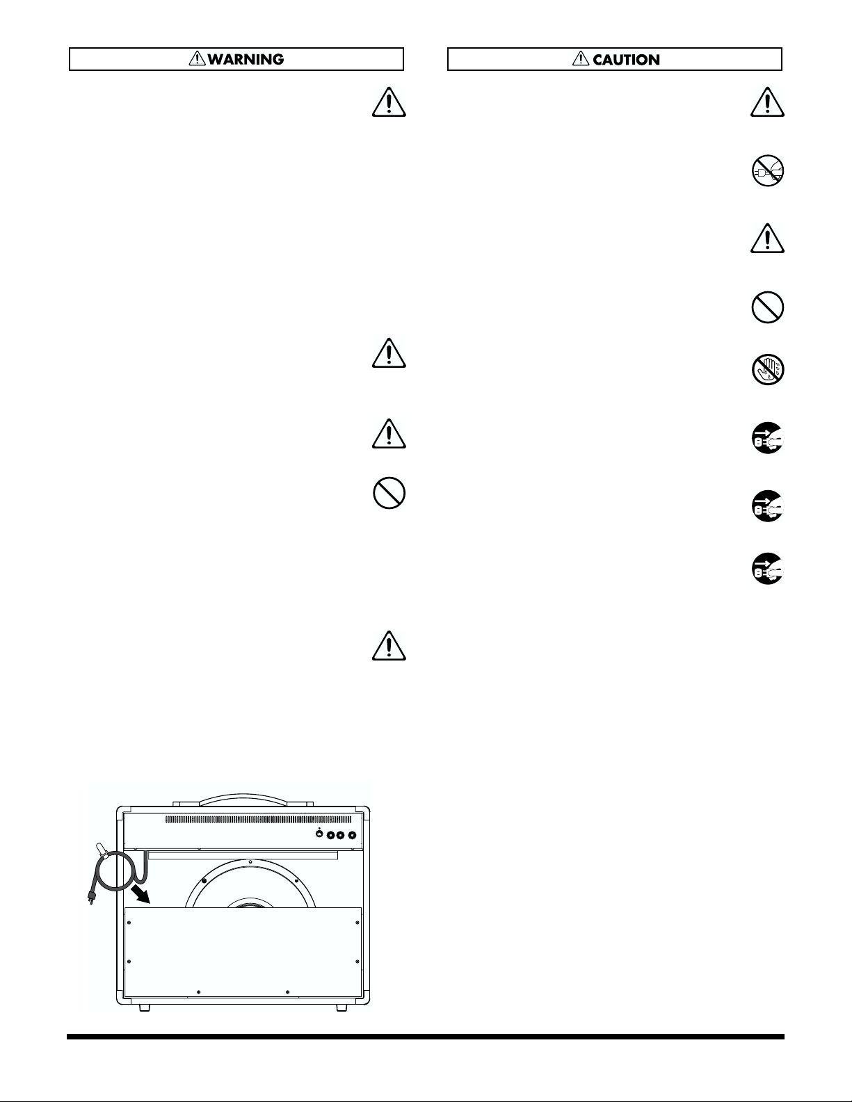
• Please stow AC cable inside cabinet as shown in Fig. A to
protect AC cable, when you carry this model or you do
not use.
When doing so, be careful not to touch the speaker unit.
101a
• The unit should be located so that its location or
position does not interfere with its proper ventilation.
..........................................................................................................
102a
• Always grasp only the plug on the power-supply
cord when plugging into, or unplugging from an
outlet.
..........................................................................................................
104
• Try to prevent cords and cables from becoming
entangled. Also, all cords and cables should be
placed so they are out of the reach of children.
..........................................................................................................
106
• Never climb on top of, nor place heavy objects on
the unit.
..........................................................................................................
107a
• Never handle the power cord or its plug with wet
hands when plugging into, or unplugging from,
an outlet.
..........................................................................................................
108a
• Before moving the unit, disconnect the power
plug from the outlet, and pull out all cords from
external devices.
..........................................................................................................
109a
• Before cleaning the unit, turn off the power and
unplug the power cord from the outlet.
..........................................................................................................
110a
• Whenever you suspect the possibility of lightning
in your area, pull the plug on the power cord out
of the outlet.
..........................................................................................................
4
Fig. A
Page 5

IMPORTANT NOTES
291b
In addition to the items listed under “IMPORTANT SAFETY INSTRUCTIONS” and “USING THE UNIT SAFELY” on pages 2
and 3–4, please read and observe the following:
This unit is equipped with a protection circuit. The protection circuit helps ensure safety by operating when excessive input
continues for a long time while the device is at a location with a high ambient temperature. Sound drop-out may occur when
the protection circuit is actuated during use. Please read through the documentation carefully to ensure correct use.
Power Supply
301
• Do not use this unit on the same power circuit with any device that will generate line noise (such as an electric motor or
variable lighting system).
307
• Before connecting this unit to other devices, turn off the power to all units. This will help prevent malfunctions and/or damage
to speakers or other devices.
Placement
351
• Using the unit near power amplifiers (or other equipment containing large power transformers) may induce hum. To alleviate
the problem, change the orientation of this unit; or move it farther away from the source of interference.
352a
• This device may interfere with radio and television reception. Do not use this device in the vicinity of such receivers.
352b
• Noise may be produced if wireless communications devices, such as cell phones, are operated in the vicinity of this unit. Such
noise could occur when receiving or initiating a call, or while conversing. Should you experience such problems, you should
relocate such wireless devices so they are at a greater distance from this unit, or switch them off.
354b
• Do not expose the unit to direct sunlight, place it near devices that radiate heat, leave it inside an enclosed vehicle, or otherwise
subject it to temperature extremes. Also, do not allow lighting devices that normally are used while their light source is very
close to the unit (such as a piano light), or powerful spotlights to shine upon the same area of the unit for extended periods of
time. Excessive heat can deform or discolor the unit.
355
• To avoid possible breakdown, do not use the unit in a wet area, such as an area exposed to rain or other moisture.
356
• Do not allow rubber, vinyl, or similar materials to remain on the unit for long periods of time. Such objects can discolor or
otherwise harmfully affect the finish.
357
• Do not put anything that contains water (e.g., flower vases) on the unit. Also, avoid the use of insecticides, perfumes, alcohol,
nail polish, spray cans, etc., near the unit. Swiftly wipe away any liquid that spills on the unit using a dry, soft cloth.
359
• Do not paste stickers, decals, or the like to this instrument. Peeling such matter off the instrument may damage the exterior
finish.
Maintenance
401a
• For everyday cleaning wipe the unit with a soft, dry cloth or one that has been slightly dampened with water. To remove
stubborn dirt, use a cloth impregnated with a mild, non-abrasive detergent. Afterwards, be sure to wipe the unit thoroughly
with a soft, dry cloth.
402
• Never use benzine, thinners, alcohol or solvents of any kind, to avoid the possibility of discoloration and/or deformation.
5
Page 6

IMPORTANT NOTES
Additional Precautions
551
• Please be aware that the contents of memory can be irretrievably lost as a result of a malfunction, or the improper operation of
the unit. To protect yourself against the risk of loosing important data, we recommend that you periodically save a backup
copy of important data you have writed on the paper.
552
• Unfortunately, it may be impossible to restore the contents of data that was stored in the unit’s memory once it has been lost.
Roland Corporation assumes no liability concerning such loss of data.
553
• Use a reasonable amount of care when using the unit’s buttons, sliders, or other controls; and when using its jacks and
connectors. Rough handling can lead to malfunctions.
556
• When connecting / disconnecting all cables, grasp the connector itself—never pull on the cable. This way you will avoid
causing shorts, or damage to the cable’s internal elements.
557
•A small amount of heat will radiate from the unit during normal operation.
558a
• To avoid disturbing your neighbors, try to keep the unit’s volume at reasonable levels. You may prefer to use headphones, so
you do not need to be concerned about those around you (especially when it is late at night).
559a
• When you need to transport the unit, package it in the box (including padding) that it came in, if possible. Otherwise, you will
need to use equivalent packaging materials.
561
• Use only the specified expression pedal (EV-5, BOSS FV-300L; sold separately). By connecting any other expression pedals, you
risk causing malfunction and/or damage to the unit.
562
• Use a cable from Roland to make the connection. If using some other make of connection cable, please note the following
precautions.
• Some connection cables contain resistors. Do not use cables that incorporate resistors for connecting to this unit. The use of
such cables can cause the sound level to be extremely low, or impossible to hear. For information on cable specifications,
contact the manufacturer of the cable.
6
Page 7

Contents
●
●
IMPORTANT SAFTY INSTRUCTIONS .......... 2
USING THE UNIT SAFELY ............................ 3
IMPORTANT NOTES...................................... 5
Basic Operation............................................. 8
Front Panel...............................................................................8
Rear Panel..............................................................................10
Turning the Power On.........................................................10
Settings for the GK Pickup (GK Setup) ..... 11
Preparations for using the GK Pickup...............................11
Basic Setting Procedure........................................................11
The Type of Settings.............................................................12
GK SETTING Settings..........................................................12
GK DIRECTION Setting......................................................12
GK PHASE Setting...............................................................13
GK S1/S2 Setting..................................................................13
GK SENS 6–1 Settings..........................................................13
GK LEVEL Setting................................................................14
COSM GUITAR............................................. 15
List of Guitar Types..............................................................15
More Advanced Operation .................................................16
SYNTH FILTER ....................................................................16
POLY OCTAVE STRING SELECT.....................................16
COSM AMPLIFIER ....................................... 17
List of Amp Types ................................................................17
Effects .......................................................... 18
EFX..........................................................................................18
CHORUS................................................................................18
FLANGER..............................................................................18
PHASER.................................................................................18
TREMOLO.............................................................................18
WAH ......................................................................................18
DELAY ...................................................................................19
CLEAR ...................................................................................19
WARM...................................................................................19
DOUBLING...........................................................................19
REVERB..................................................................................20
PLATE....................................................................................20
SPRING..................................................................................20
MEMORY ...................................................... 21
Calling Up Memory..............................................................21
Changing the Memory Settings (Edit)...............................21
Storing Knob and Button Settings to Memory (Write)....21
Confirming the Settings Stored in Memory
(Memory Utility)...................................................................21
Using the GFC-50 to Operate the VGA-3... 22
Connecting the VGA-3 and the GFC-50 ............................22
Switching Memories With the GFC-50..............................22
How to Call Up the VGA-3’s Memories
Using the GFC-50..................................................................22
Storing (Writing) to the VGA-3’s Memories
Using the GFC-50..................................................................23
Control Using an External Foot Switch or Pedal..............23
Making the SYSTEM Settings
(SYSTEM Setup) .......................................... 24
Basic Setting Procedure........................................................24
The Type of Settings .............................................................24
TUNER PITCH Setting........................................................24
TUNER LEVEL Setting........................................................24
NS THRESHOLD Setting....................................................25
FOOT SW (FS1/FS2) Setting...............................................25
EXP PEDAL MODE Setting................................................25
EXP PEDAL HOLD Setting ................................................25
MIDI OMNI MODE Setting................................................26
Additional Data............................................ 27
Restoring the Factory Settings.............................................27
Calling Up the Factory Tone Settings
for Each Individual Bank.....................................................28
Troubleshooting....................................................................29
Block Diagram/Effect Connection Procedure..................30
MIDI Implementation Chart ...............................................31
Specifications.........................................................................32
Memory Sheet (Factory Settings) ..............33
Conversions Used in This Manual
Words or numerals enclosed in square brackets [ ]
indicate panel buttons or knobs.
(Example)
[MANUAL] : MANUAL button
[VOLUME] : VOLUME knob
[1] : Memory button 1
(p. **) indicates a reference page.
7
Page 8
Basic Operation
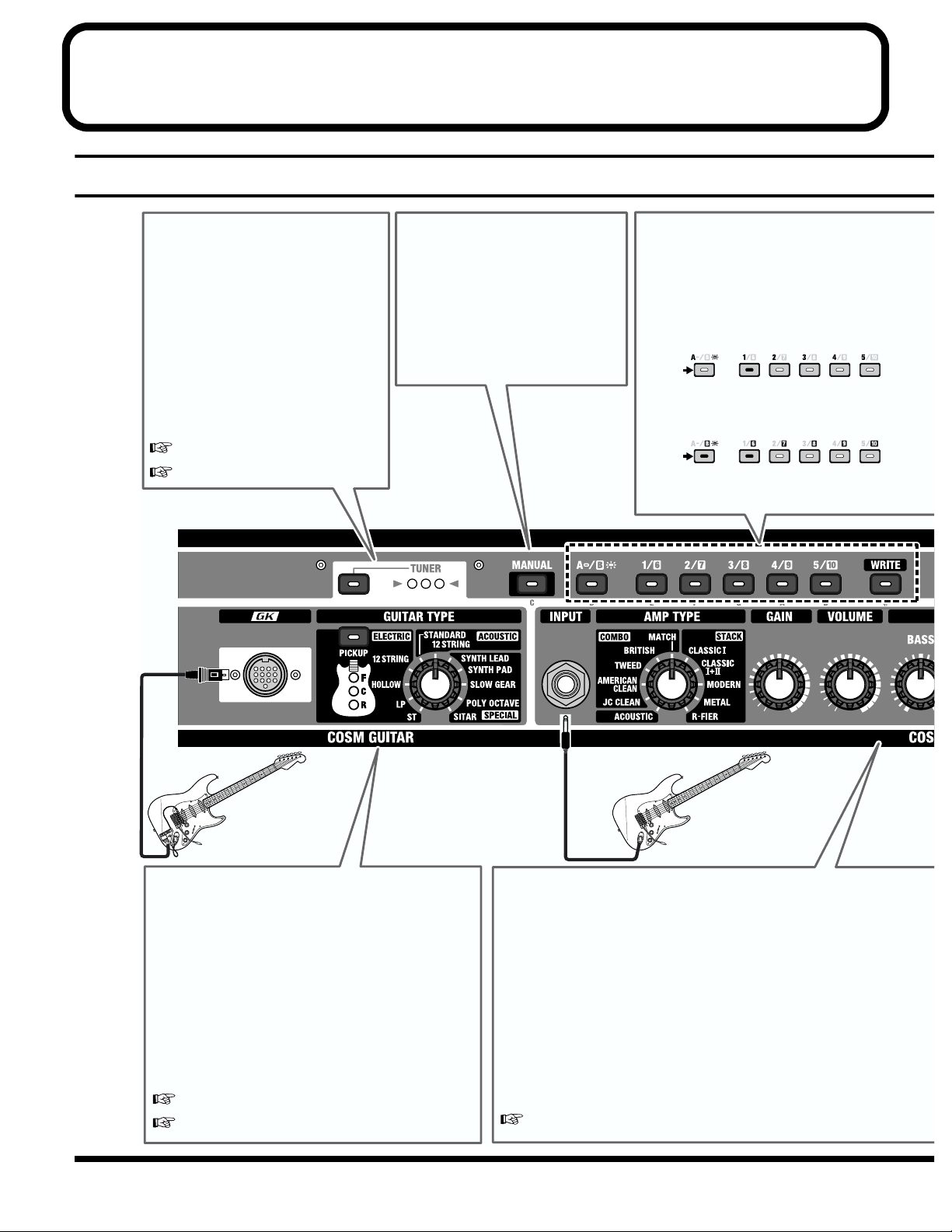
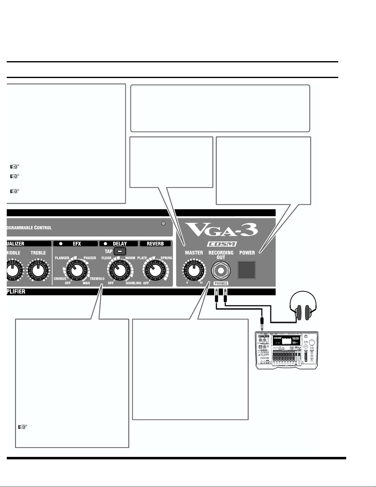
Front Panel
8
TUNER
This is a built-in chromatic tuner.
When you press the button, the
indicator lights, and the tuner is
activated.
Tune your guitar so that the green
indicator in the center lights up.
The MEMORY button indicators show
the name of the note being played.
*You can change the volume and basic
pitch when using the tuner.
“TUNER PITCH Setting” (p. 24)
“TUNER LEVEL Setting” (p. 24)
MANUAL Button
Press [MANUAL], lighting the
indicator, when you want to operate
the VGA-3 as you would a regular
analog amplifier, whereby you make
new settings with the knobs, and
sound is produced in accord with the
positions of the knobs on the front
panel.
Memory Buttons [1]–[10]
Used for calling up memories and storing
settings.
Calling up Memory
When the [A/B] button is not lighted, the
memories numbered from 1 through 5 can be
selected (in the illustration, Memory 1 is selected).
Not Lit
When the [A/B] button is lit, the memories
numbered from 6 through 10 can be selected (in
the illustration, Memory 6 is selected).
Lit
*Memories contain the factory-set knob settings.
Guitar with GK-2A
or other
GK-compatible guitar
COSM GUITAR
Connect guitars equipped with GK pickups here.
The VGA-3 includes models of eleven guitar types,
from a general guitar to more specialized sounds,
including 12-string, synth, and sitar.
[GUITAR TYPE] : Select the modeling type.
[PICKUP]: Select the pickup position.
(only electric guitar modeling)
With the SYNTH model, you can use an optional
expression pedal to change the tone in real time,
offering even richer expression in your performances.
“Settings for the GK Pickup” (p. 11)
“COSM GUITAR” (p. 15)
Conventional
Guitar
COSM AMPLIFIER
You can adjust the tone simply and easily just by turning the knobs.
You can even connect a conventional electric guitar to this amp.
[AMP TYPE]: Selects the type of amp.
[GAIN]: Adjusts the amount of distortion.
[VOLUME]: Adjusts the volume level.
[EQUALIZER] (BASS, MIDDLE, TREBLE) :
Adjust the tone in the corresponding tone range.
*Adjust the overall volume with [MASTER].
*The Acoustic Guitar Simulator function is turned on when [ACOUSTIC] is
selected. This allows you to obtain an acoustic guitar sound using an electric
guitar connected to the normal guitar input.
“COSM AMPLIFIER” (p. 17)
Page 9
Basic Operation
WRITE Button
Press this button to store knob and button
settings to memory.
Procedure
1. Press [WRITE].
2. Press a Memory button to select the memory
number to which you want to store the
setting.
3. Press [WRITE] again.
“MEMORY” (p. 21)
“Storing (Writing) to the VGA-3’s
Memories Using the GFC-50” (p. 23)
“Memory Sheet” (p. 33)
COSM (Compsite Object Sound Modeling)
Composite Object Sound Modeling (COSM) is Roland’s innovative and
powerful sound modeling technology. COSM analyzes the many factors
that make up the original sound, such as the electrical and physical
characteristics of the original, and then produces a digital model that can
reproduce the same sound.
MASTER Knob
Adjusts the VGA-3’s speaker
volume level or the volume from
RECORDING OUT/PHONES.
*The MASTER knob settings are
not stored in memory.
POWER Switch
This turns the VGA-3’s power on and
off.
*This unit is equipped with a
protection circuit. A brief interval (a
few seconds) after power up is
required before the unit will operate
normally.
Effects
You can select effects and control their depth
by positioning the knobs appropriately.
You can use [TAP] to set the delay time to the
tempo of the song being performed.
You can use all three effects types—EFX,
delay, and reverb—simultaneously.
*The panel position markings are approximate.
Check the sound of the effects as you make
adjustments.
*When an expression pedal is connected with
EFX set to WAH, the pedal is then used for a
pedal wah effect.
“Effects” (p. 18)
RECORDING OUT/PHONES Jack
When Using RECORDING OUT
Use a standard mono plug.
When using PHONES (Headphones)
Connect a pair of headphones.
* When stereo headphones are connected, the sound
is output in mono.
*No sound is output from the VGA-3’s speaker
while the RECORDING OUT/PHONES jack is
in use.
Headphones
Recorder
9
Page 10
Basic Operation
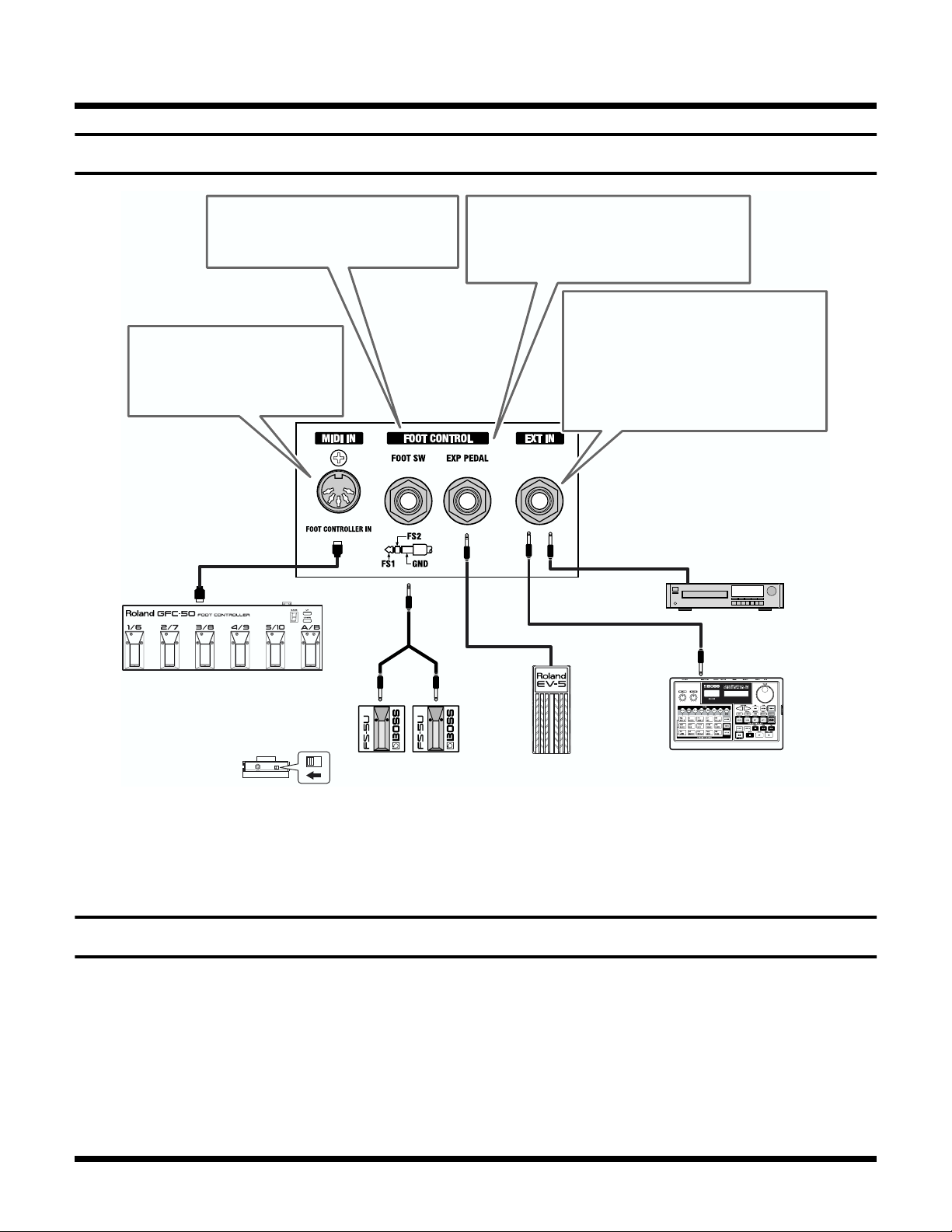
Rear Panel
fig.0020
1.
2.
3.
FOOT SW Jack
This allows you to turn effects on and
off and to switch memories, etc. (p. 25).
MIDI IN Connector
Connecting a foot controller here
allows you to use your foot to
switch memories (p. 22).
Foot Controller
(GFC-50, FC-200 etc.)
PCS-31
(optional)
FS1
(white)
EXP PEDAL Jack
This allows you to control volume and wah
(EFX) and control the SYNTH LEAD or
SYNTH PAD filters.
EXT IN Jack
This lets you input sounds from an
external device.
*Although this jack is compatible with stereo
devices, sounds are output from the speaker
and RECORDING OUT/PHONES in
mono.
CD/MD Player etc.
FS2
(red)
Set the polarity switch
as shown below.
Foot Switch
(BOSS FS-5U)
921
* To prevent malfunction and/or damage to speakers or other
devices, always turn down the volume, and turn off the power
on all devices before making any connections.
Turning the Power On
Once the connections have been completed, turn on power to
your various devices in the order specified. By turning on
devices in the wrong order, you risk causing malfunction
and/or damage to speakers and other devices.
The device connected to GK IN, INPUT or EXT IN
VGA-3
The device connected to RECORDING OUT/PHONES
Expression Pedal
(EV-5, BOSS FV-300L)
925
Backing Machine etc.
* Use only the specified expression pedal (EV-5 or BOSS FV-
300L; sold separately). By connecting any other expression
pedals, you risk causing malfunction and/or damage to the
unit.
* This unit is equipped with a protection circuit. A brief interval
(a few seconds) after power up is required before the unit will
operate normally. You should also turn down the volume level
to protect the unit from any sudden peak in volume. Even with
the volume all the way down, you may still hear some sound
when the power is switched on, but this is normal, and does
not indicate a malfunction.
10
Page 11
Settings for the GK Pickup (GK Setup)
The tonal character of the VGA-3 (COSM Guitar) is greatly affected by how the divided pickup is installed.
You need to enter the appropriate GK pickup settings (GK Setup) so as to minimize any tonal inconsistency that might arise from
differences in how the divided pickup is installed.
Be sure to redo the settings when you switch to a different guitar.
Preparations for using the GK Pickup
Attaching the GK-2A to your guitar
First, attach the GK-2A divided pickup (optional) to your
guitar.
To learn how, refer to the owner's manual for the GK-2A.
The GK-2A cannot be used with the following types
of guitar. (When attached to one of these guitars,
the GK-2A will not function correctly.)
• Guitars with unconventional string structures, such as
twelve-string guitars or pedal steel guitars
• Guitars that use nylon or gut strings
• Bass guitars
• Other guitars that, for structural reasons, have no location
where the GK-2A divided pickup can be attached
correctly
About the GK Pickup select switch
SYNTH: When using COSM guitar
MIX: When combining COSM guitar with the
normal pickup of the guitar
GUITAR: When using the normal pickup of the guitar
Basic Setting Procedure
Follow this basic process to set the GK pickup settings (GK
Setup).
Start the GK Setup
1. Connect a guitar equipped with a GK pickup to the
VGA-3.
2. Hold down [TUNER] and press [PICKUP].
The VGA-3 is now in the mode where settings for the GK
Setup can be made.
* The TUNER indicator ( ) lights up, and all tone
adjustments made with knobs other than [MASTER] are
disabled.
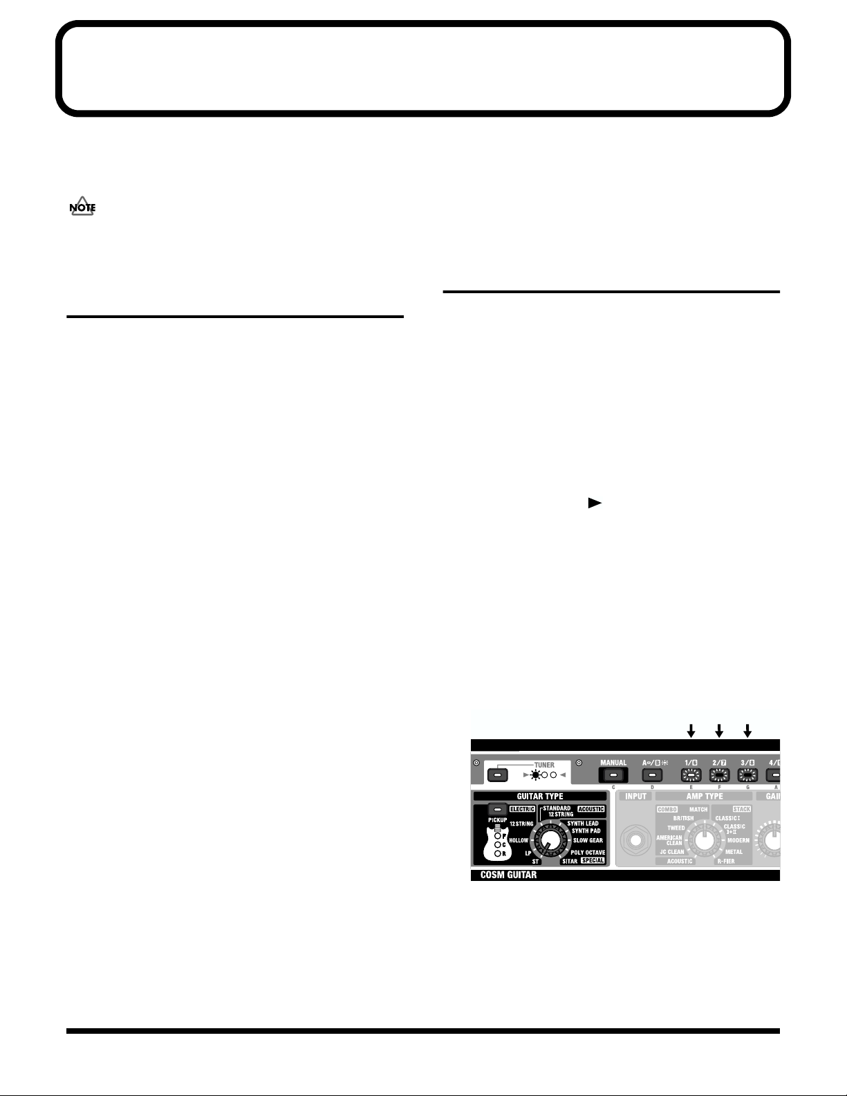
3. Rotate [GUITAR TYPE] to select the type of setting you
want to make, then press the MEMORY buttons to
select the values.
The MEMORY buttons that can be used for selecting
values are lit, while the MEMORY button corresponding
to the current value flashes.
(Ex.) When “ST” (GK SETTING) is selected
fig.0021
Flash Lit Lit
About the SYNTH VOL knob of the GK Pickup
This controls the volume of the COSM guitar.
About the S1/S2 button of the GK Pickup
This allows you to select the pickups, memories, etc. (p. 13).
* Do not turn off the power while making the settings. This may
corrupt the settings already stored in the VGA-3. Always be
sure to exit from GK Setup mode before turning off the power.
*When you have finished GK Setup, press [TUNER] once more.
* There is no prescribed sequence for the GK Setup settings.
You are free to set only the parameters needed.
11
Page 12

Settings for the GK Pickup (GK Setup)
The Type of Settings
GK SETTING Settings
You can store three sets of settings in the VGA-3.
This conveniently allows you to prepare separate settings for
a multiple number of guitars equipped with a GK pickup.
fig.0022
Set C
GK DIRECTION
Set B
GK PHASE
GK DIRECTION
Set A
GK S1/S2
GK PHASE
GK DIRECTION
GK SENS 1–6
GK S1/S2
GK PHASE
GK LEVEL
GK SENS 1–6
GK S1/S2
GK LEVEL
GK SENS 1–6
GK LEVEL
1. Rotate [GUITAR TYPE] to select “ST” (GK SETTING).
2. Press a MEMORY button [1]–[3] to select the GK SETTING
set you want to enable (the settings you want to change).
Memory button Setting
[1] Set A
[2] Set B
[3] Set C
GK DIRECTION Setting
This sets the direction of the GK pickup's installation.
1. Rotate [GUITAR TYPE] to select
“LP” (GK DIRECTION).
2. Press the MEMORY button [1] or [2] to select the
direction in which the pickup is attached.
Memory button Setting
[1] NORMAL
In this direction, the cable exits on
the side of string 6.
[2] REVERSE
In this direction, the cable exits on
the side of string 1.
fig.0030
NORMAL
string 6 string 1 string 6 string 1
REVERSE
* There is no need to change the settings if you are making them
for the first time or if you are not using multiple GK settings.
In this case, select [1] Set A, the factory default setting.
* If it is difficult to determine the direction in which the GK
pickup was installed on a GK compatible guitar, try it out
initially at the [1] NORMAL setting.
If there is no response from the meter when you play string 6
during the GK SENS 6 settings (p. 13), but there is a response
when you play string 1, change the setting to [2] REVERSE.
12
Page 13

Settings for the GK Pickup (GK Setup)
GK PHASE Setting
This matches the phase of the GK pickup's sound with the
sound from the guitar's pickup.
* If the phases are not matched, the sound from each source will
interfere with each other when mixed, altering the tonal
qualities and volume levels.
1. Set the GK pickup’s select switch to “MIX.”
2. Rotate [GUITAR TYPE] to select
“HOLLOW” (GK PHASE).
3. While playing the sixth string, press MEMORY button
[1] or [2] to select the setting which does not diminish
the volume level in the low end.
Memory button Setting
[1] NORMAL
The phase will remain unchanged.
[2] INVERSE
The phase will be inverted.
GK S1/S2 Setting
This selects the functions for the GK pickup’s S1 and S2
buttons.
GK SENS 6–1 Settings
This sets the GK pickup sensitivity for each string and
adjusts the volume balance between the strings.
1. Set the GK pickup’s select switch to “SYNTH.”
2. Rotate [GUITAR TYPE] to select
“STANDARD” (GK SENS 6).
3. While playing the sixth string, press a MEMORY
button [1]–[10] to set the sensitivity for the sixth string.
The sensitivity increases the higher you set the value,
resulting in higher volume levels.
The PICKUP indicators show the level. The indicators
light from the bottom up in response to how strongly
you play the string.
* Set this to a value such that the center (C) indicator lights, and
the upper (F) indicator flashes from time to time during the
most dynamic moments of a performance. Also, monitor the
actual sound to make sure it is not distorted.
fig.0040
1. Rotate [GUITAR TYPE] to select
“12 STRING/ELECTRIC” (GK S1/S2).
2. Press MEMORY button [1] , [2] , [3], or [4] to select the
functions for the S1 and S2 buttons.
Memory button Setting
[1] PICKUP
Switching the pickup of COSM guitar
S1 button: R→C→F
S2 button: F→C→R
[2] PICKUP (REVERSE)
Switching the pickup of COSM guitar
S1 button: F→C→R
S2 button: R→C→F
[3] MANUAL/TUNER
S1 button:
Switching the Manual/Memory mode.
S2 button:
Switching the Tuner on/off.
[4] MEMORY ▼/▲
S1 button: memory number down
S2 button: memory number up
High
(Lower the SENS setting)
Memory button Setting
[1]–[10] 1–10
4. Set the sensitivity for the fifth through first strings in
the same way.
5th String: Rotate [GUITAR TYPE] to select
“12 STRING/ACOUSTIC” (GK SENS 5).
4th String: Rotate [GUITAR TYPE] to select
“SYNTH LEAD” (GK SENS 4).
3rd String: Rotate [GUITAR TYPE] to select
“SYNTH PAD” (GK SENS 3).
2nd String: Rotate [GUITAR TYPE] to select
“SLOW GEAR” (GK SENS 2).
1st String: Rotate [GUITAR TYPE] to select
“POLY OCTAVE” (GK SENS 1).
* If you cannot attain a suitable level even when the value is set
to its maximum (10), check the installation of the GK pickup
(the clearance between the strings and the pickup).
* If any string produces a particularly loud sound, lower the
sensitivity for that string in order to minimize volume
differences between strings.
Correct Low
(Raise the SENS setting)
13
Page 14

Settings for the GK Pickup (GK Setup)
GK LEVEL Setting
This sets the level for the GK pickup sound and adjusts the
volume balance with the sound from the guitar pickup.
1. Set the GK pickup’s select switch to “SYNTH.”
2. Rotate [GUITAR TYPE] to select
“SITAR” (GK LEVEL).
3. Press a MEMORY button [1]–[10] to set the level for the
GK pickup.
The level increases the higher you set the value, resulting
in higher volume levels.
Memory button Setting
[1]–[10] 1–10
Move the select switch of the GK pickup between
“SYNTH” and “GUITAR,” and adjust the volume
balance while playing your instrument in each position.
Finishing the GK SETUP
1. Press [TUNER].
* The VGA-3 automatically stores the new value of a setting at
the time the change is made. No separate action is needed to
save the settings.
GK Setup Chart
fig.0041
14
Page 15

COSM GUITAR
This section provides an introduction to the characteristics of each of the guitars modeled.
List of Guitar Types
ELECTRIC
ST
This is a solid body guitar with single coil pickups set in
three positions. The characteristically clear and delicate
sound is used in many musical genres.
LP
This is a solid body guitar with two separate humbucking
pickups. This type of guitar features a powerful sound with
good sustain, making it an indispensable sound for rock
music.
HOLLOW
This models the sound of a hollow body guitar with two
humbucking pickups. It features a sweet, boxy tone that is
used frequently in jazz music.
12 STRING
This models the unique sound of semi-hollow body twelvestring guitar equipped with two single coil pickups that was
a favorite of vocal groups in the sixties.
ACOUSTIC
STANDARD
This is the sound of an acoustic guitar with a flat top and
back.
12 STRING
This is the sound of an acoustic twelve-string guitar.
SPECIAL
SYNTH LEAD
This is an analog synth sound that is suitable for lead and
solos. This features a fat tone with a boosted midrange.
“SYNTH FILTER” (p. 16)
SYNTH PAD
This is an analog synth sound that is good for chord playing.
This sound features a wide range and gorgeous tone.
“SYNTH FILTER” (p. 16)
SLOW GEAR
This is an effect that is automatically applied according to the
way the guitar strings are picked to produce a sound
resembling that of a violin being played (see Note).
The VGA-3 processes each of the six strings independently,
allowing the type of performance expression impossible with
a conventional guitar.
(Note)
What is meant by “resembling that of a violin being played” is an effect
whereby the volume is reduced when the guitar is picked, and then it is
gradually brought back up.
POLY OCTAVE
This adds a sound one octave below the source sound.
Octaves are processed independently for each string,
providing a fat sound that is rich in expressive power.
“POLY OCTAVE STRING SELECT” (p. 16)
SITAR
This produces a sitar-like sound.
15
Page 16

COSM GUITAR
More Advanced Operation
SYNTH FILTER
With SYNTH LEAD or SYNTH PAD selected, you can use an
optional expression pedal (EV-5; optional) to shift the synth
filter.
When using an expression pedal (EV-5; optional) to shift
the synth filter, set EXP PEDAL MODE in the System
Setup to [1] VOLUME/GK/WAH or [2] GK/WAH.
“EXP PEDAL MODE Setting” (p. 25)
POLY OCTAVE STRING SELECT
When POLY OCTAVE is selected, you can then select the
strings to which the octave sound is added.
* As set at the factory, an octave sound is added to the sound
from all of the strings.
Use the following procedure to select the pattern.
1. Select POLY OCTAVE.
2. Press [PICKUP] to select the pattern.
[PICKUP] Indicator Section
fig.0050
(F) Lit
String 1–6
* The indicator goes off after a few moments if no button is
pressed.
(C) Lit
String 4–6
(R) Lit
String 5, 6
16
Page 17

COSM AMPLIFIER
This section provides an introduction to the characteristics of each modeled amp.
The trademarks listed in this document are trademarks of their respective owners, which are separate companies from
Roland. Those companies are not affiliated with Roland and have not licensed or authorized Roland‘s VGA-3. Their marks
are used solely to identify the equipment whose sound is simulated by Roland’s VGA-3.
List of Amp Types
ACOUSTIC
This original amp that gives a flat response from the low end
on up to the high frequencies. This setting is suitable for
acoustic guitar and synth sounds.
The Acoustic Guitar Simulator is turned on for normal
pickup.
COMBO
JC CLEAN
This models the Roland JC-120. The sound extends smoothly
into the high end. Can be combined with external effect
device for an even greater effect.
AMERICAN CLEAN
This is modeled on the Fender Twin Reverb amp. This amp is
used in a wide variety of musical styles, from Country, Blues,
and Jazz to Rock. This amp features rich lows and a bright
high end.
TWEED
This is modeled on the Fender Bassman 4 x 10” Combo. The
amp features a clear upper-midrange with a fat low end, and
the persistent distortion attained with a crunch tone is a
favorite of Blues-Rock guitarists.
STACK
CLASSIC I
This is modeled on the sound input to the Marshall JMP1987
Input I. The tone extends smoothly all the way up into the
presence range.
CLASSIC I+II
This is modeled on the sound of Marshall JMP1987 Inputs I
and II connected in parallel. The low end from Input II added
to the smooth Input I tone provides that representative Hard
Rock sound.
MODERN
This is modeled on the Soldano SLO-100. This is a modern
tube amp featuring a high-gain preamp.
METAL
This is modeled on the PEAVEY EVH 5150. This high-gain
amp produces heavy distortion and sustain even at low
volumes.
R-FIER
This is modeled on the MESA/Boogie Rectifier, a super highgain amp. This amp is used for Slash Metal, Grunge, and a
wide variety of other lead sounds.
MATCH
This is modeled on the Matchless D/C-30, a modern tube
combo amp used widely in different genres, from Blues and
Rock to Fusion.
About the Acoustic Guitar Simulator
Tonal quality varies with the type of electric guitar
pickups used, so try using the pickups in different
positions.
17
Page 18

Effects
This section provides an introduction to the characteristics of each effect.
EFX
Use the knob to switch to any of five different effects, CHORUS, FLANGER, PHASER, TREMOLO, or WAH. You can adjust the
amount of effect applied according to the knob position.
* The panel markings for CHORUS, FLANGER, PHASER, and TREMOLO are approximate. Check the sound of the effects as you make
adjustments.
The indicator is lit when EFX is on, and goes off when EFX is turned off. You can also use an optional foot switch (BOSS FS-5U) to
switch EFX on and off.
“FOOT SW (FS1/FS2) Setting” (p. 25)
CHORUS
This adds a slightly detuned sound to the direct sound to
give it a sense of breadth and more body.
fig.0060
FLANGER
This produces a flanging effect that adds a kind of trembling
undulation to the sound.
fig.0070
PHASER
By adding phase-shifted sound to the direct sound, this
produces a phase effect that adds a rotating sensation to the
sound.
fig.0080
TREMOLO
This is an effect that cyclically changes the volume level.
fig.0090
WAH
This effect provides a unique tone by changing the
frequencies that are filtered.
An expression pedal (EV-5; optional) is required to change
these frequencies.
fig.0100
18
Page 19

Effects
30 msecLit:
60 msecFlash:
DELAY
Use the knob to switch to any of three different Delay, CLEAR, WARM, or DOUBLING. You can adjust the amount of effect
applied according to the knob position.
* The panel markings for CLEAR, WARM, and DOUBLING are approximate. Check the sound of the effects as you make adjustments.
The indicator is lit when Delay is on, and goes off when Delay is turned off. You can also use an optional foot switch (BOSS FS5U) to switch Delay on and off.
“FOOT SW (FS1/FS2) Setting” (p. 25)
CLEAR
This provides a clear delay sound with a distinct sonic image.
fig.0110
WARM
This produces a warmer delay sound in which the higher
frequencies are de-emphasized.
fig.0120
Setting the Delay Time with TAP Input
When CLEAR or WARM is selected as the delay variation,
you press [TAP] twice in time with the tempo of the song
being performed, the [TAP] indicator flashes at the tempo at
which the button is pressed, and the delay time is set.
You can set the delay time in the range of 0–1.8 seconds.
* The interval at which the [TAP] indicator flashes shows the
approximate tempo.
You can also use an optional foot switch to set the delay time
with TAP input.
DOUBLING
This extremely short delay produces an effect that makes it
appear that two guitars are being played.
fig.0130
Changing the DOUBLING Delay Time
When DOUBLING is selected, you can select from two
different delay times.
Select the delay time with the following procedure.
1. Select the DOUBLING.
2. Press [TAP], then select the delay time.
[TAP] Indicator Section
fig.0140
“FOOT SW (FS1/FS2) Setting” (p. 25)
19
Page 20

Effects
REVERB
Use the knob to switch to any of two different Reverb,
PLATE, or SPRING. You can adjust the amount of effect
applied according to the knob position.
* The panel markings for PLATE, and SPRING are
approximate. Check the sound of the effects as you make
adjustments.
PLATE
This simulates a plate reverb (reverb unit that uses the
vibrations of a metal plate). Provides a bright reverberation
with an extended high end.
fig.0150
SPRING
Simulates a spring reverb (a reverb unit that uses the
vibrations of a spring). The interference of the vibrations of
the two springs produces a unique type of reverberation.
fig.0160
20
Page 21

MEMORY
Correspond to the setting
stored in the memory
Rotate the knob
clockwise
Rotate the knob
counterclockwise
Lit
Lit
You can store and call up ten knob and button settings on the VGA-3. Additionally, with the use of a foot controller (such as the
optional GFC-50 or FC-200), you can store and call up forty knob and button settings (p. 22).
* The settings controlled by the following external devices are also stored to the memory along with knob and button settings.
Foot Switch (EFX ON/OFF, DELAY ON/OFF), Expression Pedal (VOLUME, GK, WAH)
Calling Up Memory
1. Press MEMORY button to select the memory to be
called up.
When the [A/B] button is not lit, the memories
numbered from 1 through 5 can be selected.
When the [A/B] button is lit, the memories numbered
from 6 through 10 can be selected.
* If you want to cancel the Write procedure, press [MANUAL].
3. Press [WRITE] once more to carry out the write.
During the write, the [WRITE] indicator flashes rapidly;
the write is completed when the [WRITE] indicator stops
flashing and stays off.
Confirming the Settings Stored in Memory (Memory Utility)
Changing the Memory Settings (Edit)
This reproduces the knob positions (settings values) stored in
1. Press memory button to select the memory whose
settings are to be changed.
2. Operate the knobs/buttons.
When you change the knob or button settings, the button
indicator corresponding to the selected memory flashes.
Immediately after you switch memories, the knob
positions may not correspond to the settings stored in
the memory. When you turn a knob, the knob’s
adjustment function is enabled as you approach the
position stored in the memory. If you are not sure of the
setting stored in memory, turn the knob completely to
the left (counterclockwise); the knob’s function is
enabled at that time.
memory.
* This function is disabled whenever [MANUAL] is selected.
* During confirmation, the volume and tone are not changed
when any knob other than [MASTER] is rotated.
1. Hold down [TUNER] and press [MANUAL].
* The [TUNER] flashes.
2. Operate the knob for the setting you want to check.
* One of the TUNER meter indicators lights up.
3. While monitoring TUNER meter indicators, rotate the
knob further until the green indicator in the center is lit.
fig.0170
If before the setting is stored the mode is switched to
Manual or Memory, or the power is turned off, all
changes in the settings will be discarded. Whenever
working with important settings, be sure to carry out the
Write procedure.
Storing Knob and Button Settings to Memory (Write)
1. When you have finished making the knob and/or
button settings, press [WRITE], causing the indicator to
flash.
2. Press MEMORY button for the memory in which you
want the settings stored.
4. Repeat Steps 2 and 3 for any knob you want to check.
5. Press [TUNER] again to complete the confirmation
procedure.
21
Page 22

Using the GFC-50 to Operate the VGA-3
By connecting a GFC-50 foot controller (optional), you can use your foot to operate the VGA-3.
Use the VGA-3’s factory MIDI settings.
Connecting the VGA-3 and the GFC-50
Connect the VGA-3 and the GFC-50 with a MIDI cable.
fig.0180
MIDI IN
GFC-50
MIDI OUT
Switching Memories With the GFC-50
How to Call Up the VGA-3’s Memories Using the GFC-50
fig.0200
(1)
GFC-50
(2)
1. Press the GFC-50’s Bank button (1) to select from Banks
0, 1, 2, or 3.
2. Select a memory Number 1–10 with the GFC-50’s pedal
(2).
Here, the memory number selected with the pedal is also
indicated by the VGA-3’s memory button indicator.
If Bank 1, 2, or 3 is specified with the foot controller, and
the power is turned off and then on again, the VGA-3’s
memory still returns to Bank 0.
The VGA-3's forty memories are divided up into Banks 0, 1,
2, and 3 as shown below.
You can use the GFC-50 to call up and store (write) settings
in all of the memories.
The forty memories can be accessed by specifying them in
terms of the GFC-50's banks (0–3) and numbers (1–10).
fig.0190
Bank 3
10
10
Bank 0
12...
Bank 2
Bank 1
10
910
22
Page 23

Using the GFC-50 to Operate the VGA-3
Storing (Writing) to the VGA-3’s Memories Using the GFC-50
fig.0210
(1)(4)
VGA-3 panel
GFC-50
(3)
1. Using the VGA-3’s knobs and buttons, prepare a tone
you want to store.
(2)
Control Using an External Foot Switch or Pedal
Connecting an external foot switch or expression pedal to the
GFC-50 allows you to use your foot to control the following
VGA-3 functions.
fig.0220
Switching banks (UP/DOWN)
Same function as the
VGA-3’s FOOT SW jack (FS2)
Same function as the
VGA-3’s FOOT SW jack (FS1)
Same function as the
VGA-3’s EXP PEDAL jack
Volume
GFC-50
Rear Panel
2. Press the VGA-3’s [WRITE] (1) , causing the indicator
to flash.
3. Press the GFC-50’s pedal (2) to select which of the
Banks 0–3 in which you want to write the tone.
4. Press the GFC-50’s pedal (3) to select which of the
memory numbers 1–10 to which you want to write the
tone.
* If you want to cancel, press the VGA-3’s [MANUAL] (4).
5. Press the VGA-3’s [WRITE] (1) once more.
During the write, the [WRITE] indicator flashes rapidly;
the write is completed when the [WRITE] indicator stops
flashing and stays off.
Foot Switch
BOSS FS-5U (optional)
Set the polarity switch
as shown below.
Expression Pedal
EV-5 (optional)
When using two external expression pedals, set the EXP
PEDAL mode in the SYSTEM settings to [2] GK/WAH.
“EXP PEDAL MODE Setting” (p. 25)
23
Page 24

Making the SYSTEM Settings (SYSTEM Setup)
With the VGA-3, you can make the following system (the parameters that can be changed so that the VGA-3 operates according to
the performer’s taste and particular application) settings.
Basic Setting Procedure
Follow this basic process to make the settings for the system
(SYSTEM Setup).
Start the SYSTEM Setup
1. Hold down [TUNER] and press [PICKUP] .
The VGA-3 is now in the mode where settings for the
SYSTEM Setup can be made.
* The TUNER meter indicator ( ) lights up, and all tone
adjustments made with knobs other than [MASTER] are
disabled.
2. Rotate [AMP TYPE] to select the type of setting you
want to make, then press the MEMORY buttons to
select the values.
The TUNER meter indicator ( ) lights up.
The MEMORY buttons that can be used for selecting
values are lit, while the MEMORY button corresponding
to the current value flashes.
(Ex.) When “BRITISH” (EXP PEDAL MODE) is selected
fig.0221
Flash Lit Lit
The Type of Settings
TUNER PITCH Setting
This changes the internal tuner’s reference pitch. It can be
convenient to change this setting when you want to tune
your guitar to another instrument whose tuning cannot be
changed easily (for example, an acoustic piano).
“Reference pitch” refers to the frequency of the A4 note—
middle A on a piano—of the instruments serving as the
reference pitch for tuning.
1. Rotate [AMP TYPE] to select
“ACOUSTIC” (TUNER PITCH).
2. Press a MEMORY button [1] –[5] , [6] –[10] , or
[MANUAL] to select the reference pitch.
Memory button Setting
[1]–[5] 441 Hz–445 Hz.
[6]–[10] 436 Hz–440 Hz.
[MANUAL] 440 Hz.
TUNER LEVEL Setting
This adjusts the volume output by the VGA-3’s speaker
when the internal tuner is used.
*A special tuner tone is selected automatically when the
internal tuner is in use.
* Do not turn off the power while making the settings. This may
corrupt the settings already stored in the VGA-3. Always be
sure to exit from SYSTEM Setup mode before turning off the
power.
* When you have finished SYSTEM Setup, press [TUNER]
once more.
* There is no prescribed sequence for the SYSTEM Setup
settings. You are free to set only the parameters needed.
24
1. Rotate [AMP TYPE] to select
“JC CLEAN” (TUNER LEVEL).
2. Press a MEMORY button [1]–[10] to set the level.
Memory button Setting
[1]–[10] 0 (mute)–9
Page 25

Making the SYSTEM Settings (SYSTEM Setup)
NS THRESHOLD Setting
This sets how much of the internal noise suppressor is
applied.
The noise suppressor is an effect that reduces guitargenerated noise and hum.
1. Rotate [AMP TYPE] to select
“AMERICAN CLEAN” (NS THRESHOLD).
2. Press a MEMORY button [1]–[10] to set the amount of
effect.
Memory button Setting
[1]–[10] 0 (Off)–9
FOOT SW (FS1/FS2) Setting
This selects the action for the foot switch (BOSS FS-5U;
optional) connected to the FOOT SW jack.
1. Rotate [AMP TYPE] to select
“TWEED” (FOOT SW (FS1/FS2) ).
2. Press MEMORY button [1], [2], [3], or [4] to select the
function for the foot switch.
Memory button Setting
[1] EFX/DELAY
FS1: Switchng the EFX on/off
FS2: Switchng the Delay on/off
[2] MEMORY ▼/▲
FS1: Memory number down
FS2: Memory number up
[3] TAP/DELAY
FS1: Tap input
FS2: Switchng the Delay on/off
[4] MANUAL/TUNER
FS1:
Switching the Manual/Memory mode
FS2:
Switchng the Tuner on/off
* When a single foot switch is connected with one cable to the
FOOT SW jack, the switch is used for FS1 function.
EXP PEDAL MODE Setting
This selects the pedal function when an expression pedal is
connected.
1. Rotate [AMP TYPE] to select
“BRITISH” (EXP PEDAL MODE).
2. Press MEMORY button [1], [2], or [3] to select the
function for the expression pedal.
Memory button Setting
[1] VOLUME/GK/WAH
• When GUITAR TYPE is set to
SYNTH LEAD or SYNTH PAD,
the pedal controls the filter.
• When WAH is selected for EFX,
it functions as a wah pedal.
• With all other settings, it functions
as a volume pedal.
[2] GK/WAH
• When GUITAR TYPE is set to
SYNTH LEAD or SYNTH PAD,
the pedal controls the filter.
• When WAH is selected for EFX,
it functions as a wah pedal.
[3] VOLUME
The pedal functions as a volume
pedal at all times.
EXP PEDAL HOLD Setting
This selects the action for the expression pedal when
switching memories.
1. Rotate [AMP TYPE] to select
“MATCH” (EXP PEDAL HOLD).
2. Press MEMORY button [1] or [2] to select the function
for the expression pedal.
Memory button Setting
[1] ON
When memories are switched, the
volume (setting) will be as specified
by the position of the pedal.
[2] OFF
When memories are switched, the
level settings stored in the memories
are used, regardless of the pedal
position.
The pedal functions as an expression pedal as soon as it is adjusted.
25
Page 26

Making the SYSTEM Settings (SYSTEM Setup)
MIDI OMNI MODE Setting
You can set the MIDI Receive channel to Omni ON, whereby
MIDI is received over any channel; or Omni OFF, whereby
channel 1 is used only.
1. Rotate [AMP TYPE] to select
“CLASSIC I” (MIDI OMNI MODE).
2. Press MEMORY button [1] or [2] to set the MIDI OMNI
MODE.
Memory button Setting
[1] ON
Data can be received on any channel
(Omni On).
[2] OFF
Only MIDI channel 1 is used (Omni
Off).
This will function only with the channel on the transmitting MIDI device
set to 1.
SYSTEM Setup Chart
fig.0221
Finishing the SYSTEM Setup
1. Press [TUNER].
* The settings are stored in the VGA-3 at the time the settings
values are changed. No separate action is needed to save the
settings.
26
Page 27

Additional Data
Restoring the Factory Settings
The data created up to the point when the factory settings are restored is lost.
When Restoring All Settings to
Their Factory Settings
You can reinitialize the content of the VGA-3’s forty
memories, GK Setup settings, and the SYSTEM Setup
settings to their original factory settings.
1. Hold down [WRITE] while you switch ON the POWER
switch.
MEMORY [1] flashes, while MEMORY [2] and [3]
remain lit.
fig.0230
Flash Lit Lit
* If you want to cancel the reset, turn the power off.
2. If you want to continue and reinitialize the data, press
[WRITE] two times.
The [WRITE] indicator flashes, and when the settings are
completed, the VGA-3 returns to MEMORY Number 1.
3. If you want to continue and reinitialize the data, press
[WRITE] two times.
The [WRITE] indicator flashes, and when the settings are
completed, the VGA-3 returns to MEMORY Number 1.
When Restoring GK Setup settings and SYSTEM
Setup Settings to Their Factory Settings
1. Hold down [WRITE] while you switch ON the POWER
switch.
MEMORY [1] flashes, while MEMORY [2] and [3]
remain lit.
fig.0230
2. Press MEMORY button [3].
MEMORY [3] flashes, while MEMORY [1] and [2]
remain lit.
fig.0250
Lit Lit Flash
When Restoring Only the Memories
to Their Factory Settings
1. Hold down [WRITE] while you switch ON the POWER
switch.
MEMORY [1] flashes, while MEMORY [2] and [3]
remain lit.
2. Press MEMORY button [2].
MEMORY [2] flashes, while MEMORY [1] and [3]
remain lit.
fig.0240
Lit Flash Lit
* If you want to cancel the reset, turn the power off.
* If you want to cancel the reset, turn the power off.
3. If you want to continue and reinitialize the data, press
[WRITE] two times.
The [WRITE] indicator flashes, and when the settings are
completed, the VGA-3 returns to MEMORY Number 1.
27
Page 28

Additional Data
Calling Up the Factory Tone Settings for Each Individual Bank
You can select any one of the Banks 0–3 listed on the Memory Sheet (p. 33) and call up that bank’s factory-loaded settings to
MEMORY buttons 1–10.
* Calling up these settings clears all of the Memories 1–10 previously stored in Bank 0.
1. While holding down the Memory button corresponding to the bank on the Memory Sheet that you want to call up, switch
ON the POWER switch.
To call up the Memory Sheet Bank 0 tone settings: [1/6]
To call up the Memory Sheet Bank 1 tone settings: [2/7]
To call up the Memory Sheet Bank 2 tone settings: [3/8]
To call up the Memory Sheet Bank 3 tone settings: [4/9]
For example, if you want to call up the tone settings for Bank 2 on the Memory Sheet, hold down [3/8] and switch the power
on. The [3/8] indicator flashes.
* If you want to cancel the operation, turn the power off.
2. Press [WRITE] two times.
The [WRITE] indicator flashes; once the settings have been called up, the VGA-3 returns to memory Number 1.
28
Page 29

Additional Data
Troubleshooting
This section explains some things that might go wrong when using the VGA-3, and what needs to be done to correct the
problem.If you think there may be something wrong with your VGA-3, please check through the following first. If these
suggestions don't fix the problem, then go ahead and contact the store you bought it from, or your nearest Roland Service Station.
Trouble with the Sound
Odd Sound / No Sound When Guitar Is Played
● Is the value for the [MASTER], [GAIN], or [VOLUME]
knobs, or for the [GAIN] or [VOLUME] settings stored
in the memory set to “0”?
➔ Raise the volume to a suitable level.
● Are the [BASS], [MIDDLE], or [TREBLE] knobs set to
“0”?
➔ Depending on the model selected with the Amp Type (p.
17), no sound may be produced when [BASS],
[MIDDLE], and [TREBLE] are all set to “0.”
● Are you using an expression pedal?
➔ There may be no sound produced when the pedal
portion is set to the released position. Try operating the
pedal.
● If controlling the volume with MIDI, was the MIDI
connection disrupted while the volume was set to “0”?
➔ Reconnect the MIDI device and raise the volume, or turn
the VGA-3’s power off and then on again.
Internal Effects Not Being Applied
● Is a foot switch connected?
➔ If the effect has been turned off with the foot switch, you
can turn the effect on by returning the knob to the “0”
position.
Wah Sound Not Produced
➔ An expression pedal (the optional EV-5) is required to
alter the filter used for the wah effect.
Interruptions in the Sound
● Is the noise suppressor effect set near “10” (higher
threshold)?
➔ Make a lower noise suppressor effect setting (p. 25).
The volume level of the instrument connected
to EXT IN is too low
● Could you be using a connection cable that contains a
resistor?
➔ Use a connection cable that does not contain a resistor.
● Is TUNER set to ON?
➔ Turn TUNER off, or set the volume to be used for the
TUNER function (p. 24).
● Is the unit in SYSTEM SETUP mode?
➔ Exit SYSTEM SETUP mode. Depending on the SYSTEM
SETUP parameters, sounds may not be output.
● Is there anything plugged into the RECORDING OUT/
PHONES jack?
➔ Disconnect the plug. No sound is output from the built-
in speaker when anything is plugged into the
RECORDING OUT/PHONES jack.
The COSM GUITAR sound isn’t right
● Is the GK pickup setting correctly?
➔ Check the GK pickup setting (p. 11).
Other Problems
VGA-3 Receives Commands from Foot Controller or
Other Device, But Memories Do Not Switch
● Is the external device transmitting over a MIDI channel
that cannot be received by the VGA-3?
➔ Set the MIDI channel on the external device to Channel
1. Otherwise, set MIDI OMNI MODE in the VGA-3’s
MIDI settings to ON (p. 26).
Tuner Meter Indicator Flashes With MIDI
Device In Use
● Could the external MIDI device have transmitted a
large volume of data all at once?
➔ After the indicator flashes for a short while, the VGA-3
automatically returns to the condition it was in before
receiving the data. Reduce the amount of data that will
be transmitted by the external device, then have it send
the data again.
29
Page 30

Additional Data
Block Diagram/Effect Connection Procedure
fig.0251
INPUT
Guitar
Input
Select Switch
GK
MANUAL (Knob)
Acoustic
Guitar
Simulator
COSM
GUITAR
Acoustic Simulator
On/Off Switch
EFX
(WAH)
COSM
AMP
TUNER
MEMORY
EFX
EXT IN
DELAY
REVERB
MASTER
AMP
Speaker
Mute Switch
Cabinet &
Speaker
Simulator
SPEAKER
RECORDING OUT
/
PHONES
MIDI IN Audio Signal
Foot Switch
Control Signal
Expression Pedal
* Wherever a block contains one or more icons, it means that some of the parameters of that block can be controlled using the external
controller(s) that the icon(s) represent(s).
* An EFX effect is placed either before or after the COSM amplifier, depending on the effect selected. WAH is before, and others are placed
after.
30
Page 31

MIDI Implementation Chart
V-GUITAR AMPLIFIER
Model VGA-3
MIDI Implementation Chart
Additional Data
Date : Oct. 1, 2002
Version : 1.00
Basic
Channel
Mode
Note
Number :
Velocity
After
Touch
Pitch Bend
Control
Change
Function...
Default
Changed
Default
Messages
Altered
True Voice
Note ON
Note OFF
Key's
Ch's
7
16
64
80
Transmitted Recognized Remarks
X
X
X
X
**************
X
**************
X
X
X
X
X
X
X
X
X
1–16 / 1
X
OMNI ON/OFF
X
X
X
X
X
X
X
O
O
O
O
Only ch. 1 (omni off)
Memorized
Volume
Volume / GK / Wah
EFX / Memory down /
Tap / Manual
Delay / Memory up /
Delay / Tuner
*1
*2
*3
*4
Prog
Change
System Exclusive
System
Common
System
Real Time
Aux
Message
Notes
Mode 1 : OMNI ON, POLY
Mode 3 : OMNI OFF, POLY
: True #
: Song Pos
: Song Sel
: Tune
: Clock
: Command
: All sound off
Local ON/OFF
:
: All Notes OFF
: Active Sense
: Reset
X
X
O
X
X
X
X
X
X
X
X
X
X
* 1 Depends on extension pedal.
Depends on extension pedal. Functions the same as the VGA-3’s EXP PEDAL.
* 2
The function is selected according to the system settings.
* 3
Functions the same as the VGA-3’s FOOT SW tip (FS1). The function is selected according to the system settings.
* 4
Functions the same as the VGA-3’s FOOT SW ring (FS2). The function is selected according to the system settings.
Mode 2 : OMNI ON, MONO
Mode 4 : OMNI OFF, MONO
O
1–40
O
X
X
X
X
X
X
X
X
X
X
O : Yes
X : No
31
Page 32

Additional Data
Specifications
VGA-3: V-GUITAR AMPLIFIER
●Rated Power Output
50W
●Patches
10 (Recalled from Panel)
40 (Recalled from MIDI Foot Controller)
●Nominal Input Level (1 kHz)
INPUT: -10 dBu
EXT INPUT: -10 dBu
*0 dBu = 0.775 Vrms
●Speakers
30 cm (12 inches) x 1
●Controls
COSM GUITAR Section
GUITAR TYPE Knob
PICKUP Button
COSM AMPLIFIER Section
AMP TYPE Knob
GAIN Knob
VOLUME Knob
EQUALIZER Knobs (BASS, MIDDLE, TREBLE)
EFX Knob
DELAY Knob
TAP Button
REVERB Knob
Master Section
TUNER Button
MANUAL Button
Memory Buttons (A/B, 1/6, 2/7, 3/8, 4/9, 5/10)
WRITE Button
MASTER Knob
POWER Switch
●Connectors
GK IN Connector
INPUT Jack
RECORDING OUT/PHONES Jack
EXT INPUT Jack
EXP PEDAL Jack
FOOT SW Jack
MIDI IN Connector
●Power Supply
AC 117 V, AC 230 V, AC 240 V
●Power Consumption
55W
●Dimensions
586 (W) x 260 (D) x 480 (H) mm
23-1/8 (W) x 10-1/4 (D) x 18-15/16 (H) inches
●Weight
18.5 kg
40 lbs 13 oz
●Accessories
Owner's Manual
●Options
Divided Pickup: GK-2A
Foot Controller: GFC-50
MIDI Foot Controller: FC-200
Expression Pedal: EV-5/FV-300L (BOSS)
Footswitch (momentary): FS-5U (BOSS)
Connection cable: PCS-31
GK Cable: GKC-3 (3 m)/GKC-5 (5 m)/GKC-10 (10 m)
In the interset of product improvement, the specifications
and/or appearance of this unit are subject to change without
prior notice.
32
Page 33

Memory Sheet (Factory Settings)
Bank
No. Name GUITAR TYPE AMP TYPE EFX DELAY REVERB
1 HEAVY POLY OCTAVE R-FIER CLEAR PLATE
2 BRIT CRUNCH ST BRITISH
3 JC CHORUS ST JC CLEAN CHORUS CLEAR PLATE
4 SWAMPY COMBO ST AMERICAN CLEAN TREMOLO SPRING
5 CLASSIC STACK LP CLASSIC I PLATE
0
6 RICH ACOUSTIC STANDARD ACOUSTIC CLEAR PLATE
7 BLUESY OCTAVE POLY OCTAVE MATCH CLEAR
8 BRIGHT JAZZ HOLLOW JC CLEAN PLATE
9 ROCK 12 12STRING(E) AMERICAN CLEAN SPRING
10 JUNO BRASS SYNTH LEAD ACOUSTIC CHORUS WARM PLATE
1 STRAIGHT JC ST JC CLEAN PLATE
2 LIVERPOOL 12STRING(E) BRITISH SPRING
3 TWEED BLUES ST TWEED WARM SPRING
4 SCOOPED CRUNCH ST BRITISH PLATE
5 DRIVEN D/C ST MATCH CLEAR
1
6 HAZY DRIVE ST CLASSIC I PLATE
7 AIRY LEAD ST CLASSIC I+II WARM SPRING
8 TRUE BRIT LP MODERN WARM PLATE
9 METAL STACK LP METAL CLEAR PLATE
10 LOW RIFFS LP R-FIER
DOUBLING
1 MIXED PICKUP ST JC CLEAN PLATE
2 DARK 175 HOLLOW AMERICAN CLEAN WARM PLATE
3 BRIGHT E12 12 STRING(E) JC CLEAN CLEAR PLATE
4 OCTAVE SOLO POLY OCTAVE AMERICAN CLEAN PLATE
5 MELODIC SWELL SLOW GEAR ACOUSTIC CLEAR PLATE
2
6 STAGE ACOUSTIC STANDARD ACOUSTIC PLATE
7 DOUBLE STRING 12 STRING(A) ACOUSTIC PLATE
8 DIMENSION SITAR SITAR ACOUSTIC CHORUS CLEAR PLATE
9 SOLO SYNTH SYNTH LEAD ACOUSTIC WARM PLATE
10 SAW PAD SYNTH PAD ACOUSTIC CHORUS CLEAR PLATE
1 CHORUS LEAD LP METAL CHORUS CLEAR PLATE
2 FLANGE LEAD ST METAL FLANGER PLATE
3 PHASE CLEAN LP JC CLEAN PHASER PLATE
4 TREMOLO CLEAN LP AMERICAN CLEAN TREMOLO SPRING
5 WAH LEAD LP MODERN WAH CLEAR PLATE
3
6 RHYTHMIC DELAY ST JC CLEAN WARM PLATE
7 TEXAS ROTAR ST CLASSIC I PHASER SPRING
8 INCENSE SITAR TWEED SPRING
9 SLOW PAD SLOW GEAR ACOUSTIC CHORUS WARM PLATE
10 SLICED SYNTH SYNTH PAD CLASSIC I+II TREMOLO CLEAR PLATE
* The logo used in the chart above indicates COSM guitar effects available when GK IN (i.e., a guitar with a GK pickup) is used.
COSM guitar effects are not available when INPUT (a normal guitar) is used.
33
Page 34

MEMO
34
Page 35

For EU Countries
This product complies with the requirements of European Directives EMC 89/336/EEC and LVD 73/23/EEC.
For the USA
FEDERAL COMMUNICATIONS COMMISSION
RADIO FREQUENCY INTERFERENCE STATEMENT
This equipment has been tested and found to comply with the limits for a Class B digital device, pursuant to Part 15 of the
FCC Rules. These limits are designed to provide reasonable protection against harmful interference in a residential
installation. This equipment generates, uses, and can radiate radio frequency energy and, if not installed and used in
accordance with the instructions, may cause harmful interference to radio communications. However, there is no guarantee
that interference will not occur in a particular installation. If this equipment does cause harmful interference to radio or
television reception, which can be determined by turning the equipment off and on, the user is encouraged to try to correct the
interference by one or more of the following measures:
– Reorient or relocate the receiving antenna.
– Increase the separation between the equipment and receiver.
– Connect the equipment into an outlet on a circuit different from that to which the receiver is connected.
– Consult the dealer or an experienced radio/TV technician for help.
This device complies with Part 15 of the FCC Rules. Operation is subject to the following two conditions:
(1) This device may not cause harmful interference, and
(2) This device must accept any interference received, including interference that may cause undesired operation.
Unauthorized changes or modification to this system can void the users authority to operate this equipment.
This equipment requires shielded interface cables in order to meet FCC class B Limit.
For Canada
NOTICE
This Class B digital apparatus meets all requirements of the Canadian Interference-Causing Equipment Regulations.
AVIS
Cet appareil numérique de la classe B respecte toutes les exigences du Règlement sur le matériel brouilleur du Canada.
Page 36

xxxxxxxx ’00-xx-xx-xxx
 Loading...