

Roland TD-50KVX Data List
Data List
Copyright © 2016 ROLAND CORPORATION

Contents
DRUM KIT . . . . . . . . . . . . . . . . . . . . . . . . . . . . . . . . . . . . . . . . . . . . . . . . . 3
DRUM KIT Screen . . . . . . . . . . . . . . . . . . . . . . . . . . . . . . . . . . . . . . . . 3
KIT SETTINGS . . . . . . . . . . . . . . . . . . . . . . . . . . . . . . . . . . . . . . . . . . . 3
KIT SETTINGS 1 (page 1) . . . . . . . . . . . . . . . . . . . . . . . . . . . . . 3
KIT SETTINGS 2 (page 2) . . . . . . . . . . . . . . . . . . . . . . . . . . . . . 4
PAD CONTROL (page 3) . . . . . . . . . . . . . . . . . . . . . . . . . . . . . 4
PAD MIDI (page 4) . . . . . . . . . . . . . . . . . . . . . . . . . . . . . . . . . . 5
KIT CUSTOMIZE . . . . . . . . . . . . . . . . . . . . . . . . . . . . . . . . . . . . . . . . . . . 6
INSTRUMENT . . . . . . . . . . . . . . . . . . . . . . . . . . . . . . . . . . . . . . . . . . . 6
INSTRUMENT (page 1) . . . . . . . . . . . . . . . . . . . . . . . . . . . . . . 6
MIC POSITION (page 2) . . . . . . . . . . . . . . . . . . . . . . . . . . . . . 9
TRANSIENT (page 3) . . . . . . . . . . . . . . . . . . . . . . . . . . . . . . . . 9
SUB INST (page 4) . . . . . . . . . . . . . . . . . . . . . . . . . . . . . . . . . . 10
AMBIENCE . . . . . . . . . . . . . . . . . . . . . . . . . . . . . . . . . . . . . . . . . . . . . . 11
AMBIENCE LEVEL (page 1) . . . . . . . . . . . . . . . . . . . . . . . . . . . 11
ROOM (page 2) . . . . . . . . . . . . . . . . . . . . . . . . . . . . . . . . . . . . 11
REVERB (page 3) . . . . . . . . . . . . . . . . . . . . . . . . . . . . . . . . . . . 12
STEREO ENHANCER (page 4) . . . . . . . . . . . . . . . . . . . . . . . . . 12
MIXER . . . . . . . . . . . . . . . . . . . . . . . . . . . . . . . . . . . . . . . . . . . . . . . . . . 13
MIXER VOLUME (page 1) . . . . . . . . . . . . . . . . . . . . . . . . . . . . 13
PAD EQ (page 2) . . . . . . . . . . . . . . . . . . . . . . . . . . . . . . . . . . . 14
PAD COMP (page 3) . . . . . . . . . . . . . . . . . . . . . . . . . . . . . . . . 14
MULTI EFFECT (MFX) (page 4) . . . . . . . . . . . . . . . . . . . . . . . . 15
MASTER COMP (page 5) . . . . . . . . . . . . . . . . . . . . . . . . . . . . . 16
MASTER EQ (page 6) . . . . . . . . . . . . . . . . . . . . . . . . . . . . . . . . 17
USER SAMPLE . . . . . . . . . . . . . . . . . . . . . . . . . . . . . . . . . . . . . . . . . . . . . 18
SAMPLE LIST. . . . . . . . . . . . . . . . . . . . . . . . . . . . . . . . . . . . . . . 18
SONG . . . . . . . . . . . . . . . . . . . . . . . . . . . . . . . . . . . . . . . . . . . . . . . . . . . . . 19
SONG (page 1) . . . . . . . . . . . . . . . . . . . . . . . . . . . . . . . . . . . . . 19
SONG INFO (page 2) . . . . . . . . . . . . . . . . . . . . . . . . . . . . . . . . 19
SET LIST. . . . . . . . . . . . . . . . . . . . . . . . . . . . . . . . . . . . . . . . . . . . . . . . . . . 20
SETUP . . . . . . . . . . . . . . . . . . . . . . . . . . . . . . . . . . . . . . . . . . . . 20
CLICK . . . . . . . . . . . . . . . . . . . . . . . . . . . . . . . . . . . . . . . . . . . . . . . . . . . . . 21
TRIGGER . . . . . . . . . . . . . . . . . . . . . . . . . . . . . . . . . . . . . . . . . . . . . . . . . . 22
TRIG BASIC (page 1) . . . . . . . . . . . . . . . . . . . . . . . . . . . . . . . . 22
TRIG ADVANCED (page 2) . . . . . . . . . . . . . . . . . . . . . . . . . . . 24
TRIG MONITOR (page 3) . . . . . . . . . . . . . . . . . . . . . . . . . . . . . 26
Multi-Eect Parameters . . . . . . . . . . . . . . . . . . . . . . . . . . . . . . . . . . . 34
DELAY . . . . . . . . . . . . . . . . . . . . . . . . . . . . . . . . . . . . . . . . . . . . 35
TAPE ECHO . . . . . . . . . . . . . . . . . . . . . . . . . . . . . . . . . . . . . . . . 35
REVERSE DELAY . . . . . . . . . . . . . . . . . . . . . . . . . . . . . . . . . . . . 35
3TAP PAN DELAY . . . . . . . . . . . . . . . . . . . . . . . . . . . . . . . . . . . 35
OD0DELAY . . . . . . . . . . . . . . . . . . . . . . . . . . . . . . . . . . . . . . 36
DS0DELAY . . . . . . . . . . . . . . . . . . . . . . . . . . . . . . . . . . . . . . . 36
CHORUS . . . . . . . . . . . . . . . . . . . . . . . . . . . . . . . . . . . . . . . . . . 36
SPACE-D . . . . . . . . . . . . . . . . . . . . . . . . . . . . . . . . . . . . . . . . . . 36
OD0CHORUS . . . . . . . . . . . . . . . . . . . . . . . . . . . . . . . . . . . . 36
DS0CHORUS . . . . . . . . . . . . . . . . . . . . . . . . . . . . . . . . . . . . . 36
PHASER A . . . . . . . . . . . . . . . . . . . . . . . . . . . . . . . . . . . . . . . . . 37
PHASER B . . . . . . . . . . . . . . . . . . . . . . . . . . . . . . . . . . . . . . . . . 37
STEP PHASER . . . . . . . . . . . . . . . . . . . . . . . . . . . . . . . . . . . . . . 37
FLANGER . . . . . . . . . . . . . . . . . . . . . . . . . . . . . . . . . . . . . . . . . . 37
REVERB . . . . . . . . . . . . . . . . . . . . . . . . . . . . . . . . . . . . . . . . . . . 38
LONG REVERB . . . . . . . . . . . . . . . . . . . . . . . . . . . . . . . . . . . . . 38
SUPER FILTER . . . . . . . . . . . . . . . . . . . . . . . . . . . . . . . . . . . . . . 38
FILTER+DRIVE . . . . . . . . . . . . . . . . . . . . . . . . . . . . . . . . . . . . . . 38
AUTO WAH . . . . . . . . . . . . . . . . . . . . . . . . . . . . . . . . . . . . . . . . 39
OD/DS0TWAH . . . . . . . . . . . . . . . . . . . . . . . . . . . . . . . . . . . 39
LOFI COMPRESS . . . . . . . . . . . . . . . . . . . . . . . . . . . . . . . . . . . . 39
DISTORTION . . . . . . . . . . . . . . . . . . . . . . . . . . . . . . . . . . . . . . . 39
OVERDRIVE . . . . . . . . . . . . . . . . . . . . . . . . . . . . . . . . . . . . . . . . 39
SATURATOR . . . . . . . . . . . . . . . . . . . . . . . . . . . . . . . . . . . . . . . 39
T-SCREAM . . . . . . . . . . . . . . . . . . . . . . . . . . . . . . . . . . . . . . . . . 40
BIT CRUSHER . . . . . . . . . . . . . . . . . . . . . . . . . . . . . . . . . . . . . . 40
ISOLATOR . . . . . . . . . . . . . . . . . . . . . . . . . . . . . . . . . . . . . . . . . 40
RING MODULATOR . . . . . . . . . . . . . . . . . . . . . . . . . . . . . . . . . 40
PITCH SHIFTER . . . . . . . . . . . . . . . . . . . . . . . . . . . . . . . . . . . . . 40
AUTO PAN . . . . . . . . . . . . . . . . . . . . . . . . . . . . . . . . . . . . . . . . . 40
Drum Kit List . . . . . . . . . . . . . . . . . . . . . . . . . . . . . . . . . . . . . . . . . . . . . . 41
Instrument List . . . . . . . . . . . . . . . . . . . . . . . . . . . . . . . . . . . . . . . . . . . 42
Song List . . . . . . . . . . . . . . . . . . . . . . . . . . . . . . . . . . . . . . . . . . . . . . . . . . 46
Drum Kit Parameter Structure . . . . . . . . . . . . . . . . . . . . . . . . . . . . 47
Block Diagram . . . . . . . . . . . . . . . . . . . . . . . . . . . . . . . . . . . . . . . . . . . . 48
SETUP . . . . . . . . . . . . . . . . . . . . . . . . . . . . . . . . . . . . . . . . . . . . . . . . . . . . 27
OUTPUT . . . . . . . . . . . . . . . . . . . . . . . . . . . . . . . . . . . . . . . . . . . . . . . . 27
PAD OUTPUT (page 1) . . . . . . . . . . . . . . . . . . . . . . . . . . . . . . 27
OTHER OUTPUT (page 2) . . . . . . . . . . . . . . . . . . . . . . . . . . . . 28
OUTPUT ROUTING (page 3) . . . . . . . . . . . . . . . . . . . . . . . . . . 29
USB AUDIO . . . . . . . . . . . . . . . . . . . . . . . . . . . . . . . . . . . . . . . . . . . . . 30
OPTION . . . . . . . . . . . . . . . . . . . . . . . . . . . . . . . . . . . . . . . . . . . . . . . . 30
CONTROL. . . . . . . . . . . . . . . . . . . . . . . . . . . . . . . . . . . . . . . . . . . . . . . 31
MIDI . . . . . . . . . . . . . . . . . . . . . . . . . . . . . . . . . . . . . . . . . . . . . . . . . . . 32
AUTO OFF . . . . . . . . . . . . . . . . . . . . . . . . . . . . . . . . . . . . . . . . . . . . . . 33
INFO . . . . . . . . . . . . . . . . . . . . . . . . . . . . . . . . . . . . . . . . . . . . . . . . . . . 33
2
DRUM KIT
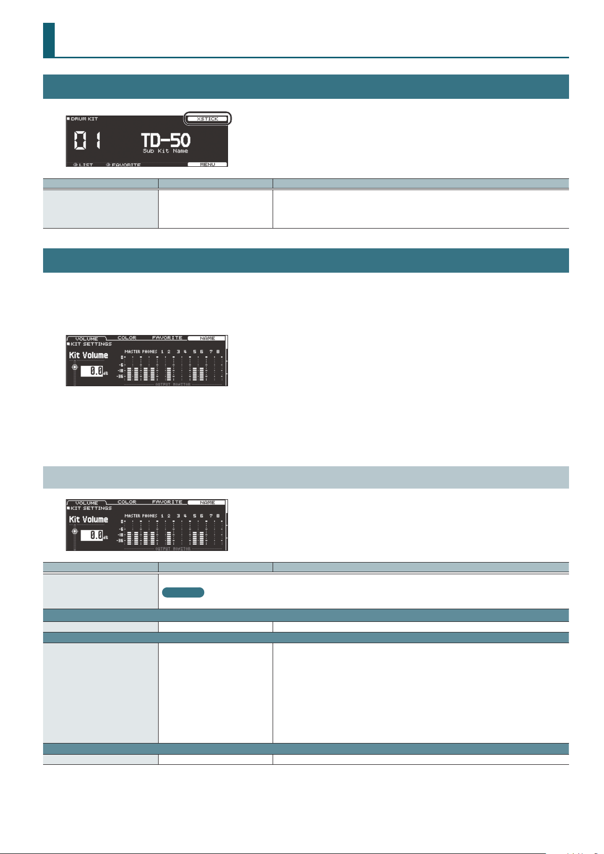
DRUM KIT Screen
Parameter Value Explanation
Species whether a snare pad produces the cross-stick sound (ON) or not (OFF).
XSTICK OFF, ON
KIT SETTINGS
1. Press the [KIT] button.
1. Press the [F5] (MENU) button.
The menu screen appears.
If the trigger input of a pad that supports both cross-stick technique and digital connection (such
as the PD-140DS) is assigned to a snare, cross-stick playing is always possible. In this case, the
screen does not show the XSTICK icon.
2. Use the PAGE [UP] [DOWN] buttons to access the editing screen.
3. Use cursor buttons to select a parameter, and use the [–] [+] buttons or the dial to edit the value.
4. Press the [KIT] button to return to the DRUM KIT screen.
KIT SETTINGS 1 (page 1)
Parameter Value Explanation
Edits the name of the drum kit.
[F4] button
VOLUME tab
Kit Volume -INF–+6.0 dB Drum kit volume
COLOR tab
Kit Color
FAVORITE tab
Favorite OFF, ON Registers (ON)/de-registers (OFF) the drum kit in favorites.
Reference
For details on how to assign a name, refer to “Renaming a Drum Kit” in the “Reference Manual” (PDF).
1: WHITE
2: RED
3: GREEN
4: BLUE
5: PINK
6: PURPLE
7: ORANGE
8: YELLOW
9: EMERALD
10: RAINBOW
Use the [KIT] button or [R1]–[R3] knobs to specify the illumination color.
3
DRUM KIT
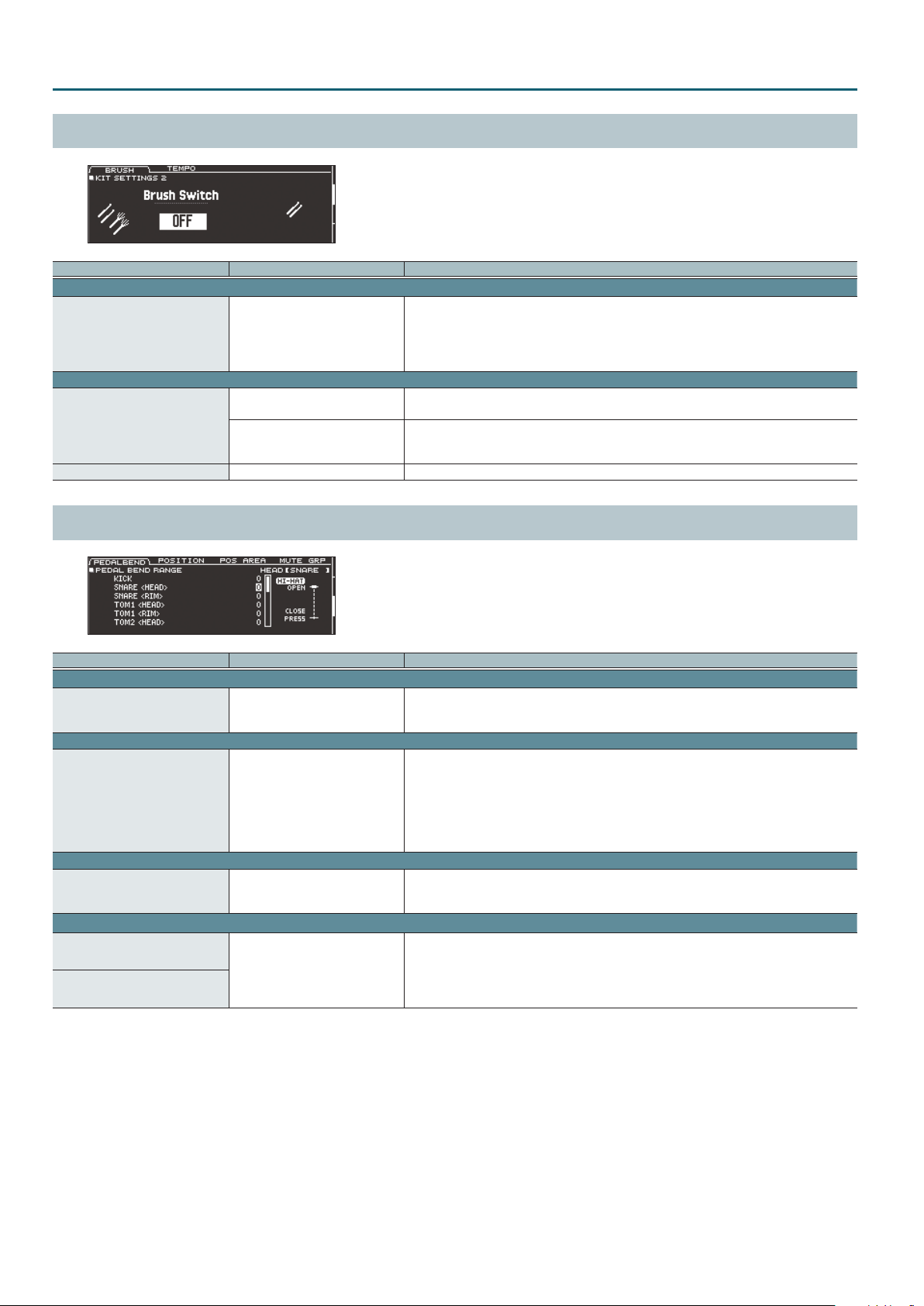
KIT SETTINGS 2 (page 2)
Parameter Value Explanation
BRUSH tab
Species whether you’re performing with sticks (OFF) or brushes (ON).
Brush Switch OFF, ON
KIT TEMPO tab
OFF
Kit Tempo
ON
Tempo 20–260 Tempo specied for each drum kit
If this is “ON,” you can perform by scraping (sweeping) the brushes.
* This is supported starting with program version 1.05. Refer to the Roland website for the latest
information.
http://www.roland.com/support/
Use a common tempo (p. 21) for the entire TD-50.
The tempo does not change when you switch drum kits.
Use the tempo that is specied by each drum kit.
The click tempo and the tempo of tempo-synchronized eects can be individually specied for
each drum kit.
PAD CONTROL (page 3)
Parameter Value Explanation
PEDALBEND tab
Species the amount of pitch change that occurs according to the depth to which you press the
Pedal Bend Range -24–0–+24
POSITION tab
Position Control*1 OFF, ON
POS AREA tab
Position Area*1 INSIDE -5–DEFAULT– OUTSIDE +5
MUTE GRP tab
MUTE SEND
– (OFF), 1–8
MUTE RECEIVE
*1 This supports the following trigger inputs.
5 SNARE
5 TOM1–4
5 The bow (head) of RIDE
5 AUX1–4
* Depending on the pad that is connected or the instrument that is selected, there might be cases in which this has no eect.
hi-hat pedal.
You can set this for each pad (head and rim separately) in semitone units.
Turns on/o tonal changes that occur depending on your strike location or the nuances of your rim
shots.
You can set this for the snare (head, rim), tom (head, rim), ride (bow), and AUX (head, rim) trigger
inputs.
Head: Strike position
Rim: Rim shot nuance
Bow: Strike position
Species the striking area for the head or rim.
“INSIDE” settings make it easier to play notes toward the inside; “OUTSIDE” settings make it easier to
play toward the outside.
Specify the mute group number.
When you strike the pad of the number specied in MUTE SEND, the sound of the pad assigned to
the same number in MUTE RECEIVE is muted.
* Even if you specify the same number in MUTE SEND and MUTE RECEIVE for the same location
(e.g., head or rim) of the same pad, muting does not occur.
4

PAD MIDI (page 4)
Parameter Value Explanation
NOTE tab
Note No.
GATE tab
Gate Time 0.1– 8.0 s Duration of the note transmitted by each pad
MIDI CH tab
MIDI Channel
MIDI note numbers transmitted and received by the hi-hat
Item Explanation
HI-HAT OPEN <BOW>
HI-HAT OPEN <EDGE>
HI-HAT CLOSE <BOW>
HI-HAT CLOSE <EDGE>
HI-HAT PEDAL MIDI note number transmitted and received by pedal hi-hat
0(C -)–127(G 9) MIDI note number transmitted and received by each pad
OFF Note messages are not transmitted or received
CH1–CH16 MIDI channel on which each pad transmits or receives note messages or control change messages
GLOBAL Transmitted and received on the transmit/receive channel specied in SETUP (p. 32)
MIDI note number transmitted and received by open hi-hat (bow, edge)
MIDI note number transmitted and received by closed hi-hat (bow, edge)
DRUM KIT
MIDI note numbers transmitted and received by the snare
Parameter Explanation
SNARE <HEAD>
SNARE <RIM>
SNARE <BRUSH> MIDI note number transmitted and received by brush sweep
SNARE <XSTICK> MIDI note number transmitted and received by cross stick
MIDI note number transmitted and received by head shot and rim shot
When setting multiple pads to the same note number
When playing the internal sound generator of the TD-50, if an incoming note number is assigned to more than one pad, that note plays the
instrument of the pad with the lowest trigger input number. If the same note number is assigned to both the head and the rim, the head instrument
is sounded.
MEMO
An asterisk (*) appears at the right of the note number for trigger inputs that are not sounded.
Example:
Note number “38 (D 2)” is set for the head and rim of trigger input 2 SNARE and the head of trigger input 3 TOM 1. In this case, when note number 38
(D2) is received, the instrument assigned to the head of trigger input 2 SNARE is played.
About the gate time
Percussion sound modules normally produce sound only in response to “Note on” messages, and ignore “Note o” messages. However generalpurpose sound modules or samplers do receive the note-o messages that are transmitted and respond by turning o the sound.
Since gate time is normally not necessary for a percussion sound module, this is set to the minimum value when the unit is shipped from the
factory. If a note-o message is received while the sound module has this setting, it is received as an extremely brief note that has almost no
time to be heard, and is nearly inaudible. (Alternatively, it is possible that this could be heard as an unwanted noise.) To avoid this, specify the
note duration of the MIDI performance data that is produced when you strike each pad.
* If the same note number is sounded again in an overlapping manner, a note-o is transmitted before transmitting note-on, even if it is
within the gate time.
5
KIT CUSTOMIZE
INSTRUMENT
1. Press the [INSTRUMENT] button.
The INSTRUMENT screen appears.
2. Select the pad that you want to edit.
3. Use the PAGE [UP] [DOWN] buttons and function buttons to select the item that you want to edit.
* The parameters that you can edit depend on the pad and instrument.
4. Use cursor buttons to select a parameter, and use the [–] [+] buttons or the dial to edit the value.
MEMO
For some parameters, you can also use the rotary knobs to edit the value.
5. Press the [KIT] button to return to the DRUM KIT screen.
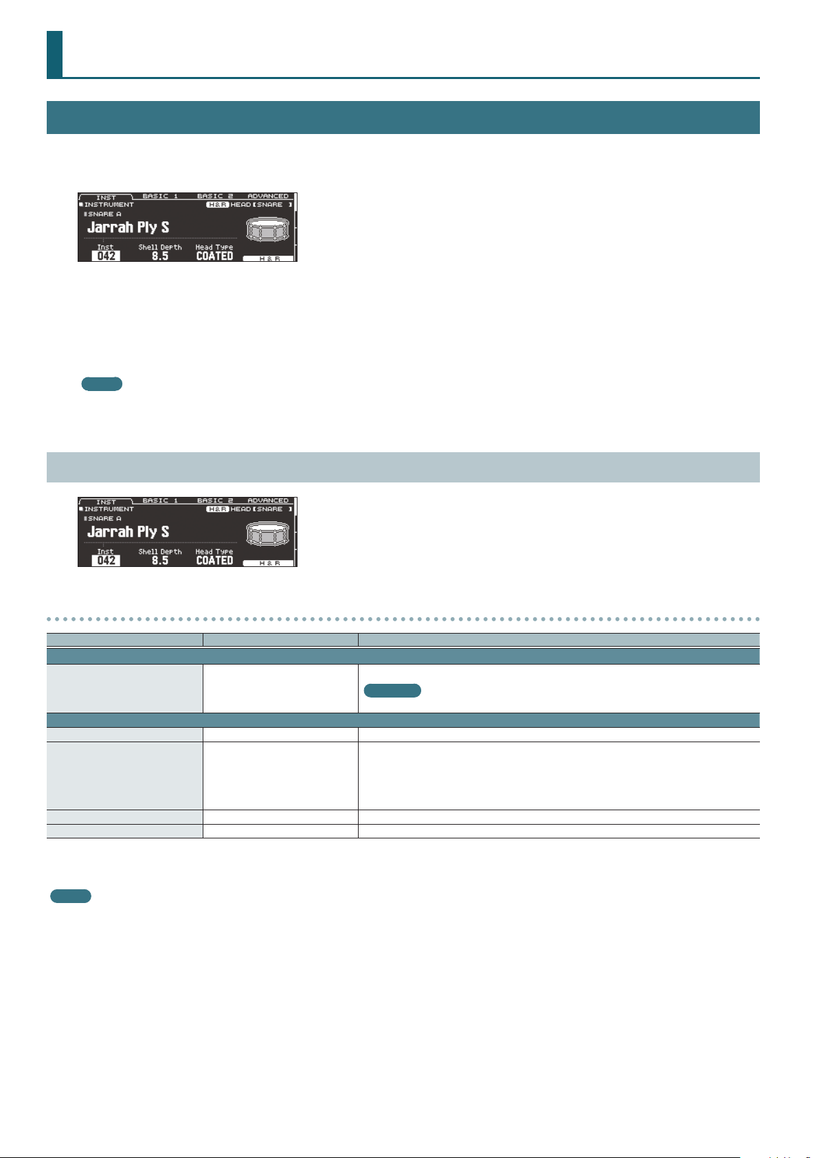
INSTRUMENT (page 1)
Parameters that can be edited for each instrument
Parameter Value Explanation
INST tab
Inst
ADVANCED tab
Pitch -4800–4800 Instrument pitch (units of one cent)
Pitch Sweep*1 -100–100
Decay*1 1–100 Length of decay
Dynamic Enhancer Sw*1, *2 OFF, ON Species whether the sense of strong strikes is enhanced (ON) or not enhanced (OFF).
*1 If a user sample is assigned to the instrument, you can’t specify Dynamic Enhancer Sw. Also, if the user sample’s Play Type (p. 18) is set to “LOOP ALT,” the Pitch Sweep and Decay
have no eect.
*2 For some instruments, this cannot be set.
MEMO
If you press the [F5] (H&R) button to turn it “ON,” you can simultaneously make settings for the head area and rim area, etc.
001– (preset)
U001–U500 (user sample)
Instrument number
Reference
For more about instruments, refer to “Instrument List” (p. 42).
After the sound begins, the pitch gradually rises (falls).
Positive (+) values make the pitch start high and then fall; negative (-) values make the pitch start
low and then rise.
Larger values produce greater change.
* In some cases, changing the Pitch setting by a large amount might limit the Pitch Sweep eect.
6

KICK A
Parameter Value Explanation
INST tab
Shell Depth 1.0–30.0 Depth of the shell
Head Type CLEAR, COATED, PINSTRIPE Type of head
BASIC 1 tab
Tuning -100–100 Tuning of the head
Muing
Beater Type FELT1, 2, WOOD, PLASTIC1, 2 Type of beater
BASIC 2 tab
Snare Buzz OFF, 1–8 Resonance to the snare
Low Level -5–NORMAL–+5 Volume of low-frequency sound
Low Decay -2–NORMAL–+2 Decay length of low-frequency sound
ADVANCED tab
Kit Resonance OFF, 1–8 Amount of resonance for the entire drum kit
OFF, TAPE1–4, BLANKET1–3, WEIGHT1, 2
Muing (muting) setting
SNARE A/CROSS STICK/SNARE BRUSH
KIT CUSTOMIZE
Parameter Value Explanation
INST tab
Shell Depth*1 1.0–30.0 Depth of the shell
Head Type*1 CLEAR, COATED, PINSTRIPE Type of head
BASIC 1 tab
Tuning -100–100 Tuning of the head
Muing OFF, TAPE1–7, DONUT1, 2 Muing (muting) setting
Overtone*1, *2 -5–NORMAL–+5 Amount of overtone components
BASIC 2 tab
Strainer Adj.*2 LOOSE1–3, MEDIUM1–3, TIGHT1–3 Tension of the strainer (resonating cords)
Wire Type*2 TYPE1–3 Type of strainer
Wire Level*2 -4–NORMAL–+5 Volume of strainer
ADVANCED tab
XStick Inst*3 1–5 Cross-stick sound selection
Cross-stick sound volume
XStick Inst Volume*3 -INF–+6.0 dB
*1 Unavailable if the instrument group is CROSS STICK.
*2 Unavailable if the instrument group is SNARE BRUSH.
*3 Only if the SNARE A/CROSS STICK instrument is assigned to the rim of the snare (or to the rim of a digitally connected pad that is assigned to snare)
* PINSTRIPE is a registered trademark of Remo Inc., U.S.A.
MEMO
The “XStick Volume” can also be edited from the MIXER DRUM KIT VOLUME screen (KIT VOL tab)
of the MIXER (p. 13).
7

KIT CUSTOMIZE
TOM A/TOM BRUSH
Parameter Value Explanation
INST tab
Shell Depth 1.0–30.0 Depth of the shell
Head Type CLEAR, COATED, PINSTRIPE Type of head
BASIC 1 tab
Tuning -100–100 Tuning of the head
Muing OFF, TAPE1–5, FELT1–4 Muing (muting) setting
Snare Buzz OFF, 1–8 Resonance to the snare
HI-HAT
Parameter Value Explanation
INST tab
Size 1.0–40.0 Hi-hat diameter
Thickness THIN-5–STANDARD–THICK +5 Thickness of the hi-hat
BASIC 1 tab
Fixed NORMAL, PRESS, CLOSE, HALF, OPEN
ADVANCED tab
Pedal HH Volume -INF–+6.0 dB
Openness of the hi-hat
If something other than “NORMAL” is selected, the openness of the hi-hat does not change,
regardless of how you press the hi-hat pedal.
Volume of pedal hi-hat
MEMO
The “Pedal HH Volume” can also be edited from the MIXER DRUM KIT VOLUME screen
(KIT VOL tab) of the MIXER (p. 13).
MEMO
The closed hi-hat position (Fixed = CLOSE) can be enabled by pressing an optional footswitch or hitting a pad switch. Please refer to “CONTROL” (p. 31).
CRASH/CHINA/SPLASH/STACKED CYMBAL
Parameter Value Explanation
INST tab
Size 1.0–40.0 Cymbal diameter
Thickness THIN-5–STANDARD–THICK +5 Thickness of the cymbal
BASIC 1 tab
Muing OFF, TAPE1–19 Muing (muting) setting
Sizzle Type OFF, RIVET, CHAIN, BEADS Type of sizzle
Sizzle Amount -3–+3 Amount of sizzle
8
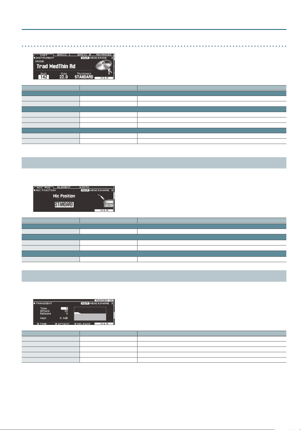
RIDE
Parameter Value Explanation
INST tab
Size 1.0–40.0 Cymbal diameter
Thickness THIN-5–STANDARD–THICK +5 Thickness of the cymbal
BASIC 1 tab
Muing OFF, TAPE1–19 Muing (muting) setting
Sizzle Type OFF, RIVET, CHAIN, BEADS Type of sizzle
Sizzle Amount -3–+3 Amount of sizzle
BASIC 2 tab
Ping Color*1 LIGHT2, 1, STANDARD, HEAVY1, 2 Tonal character of the ride’s ping sound
Ping Level*1 -4–NORMAL–+5 Volume of the ride’s ping sound
*1 For some instruments, these settings are not available.
MIC POSITION (page 2)
You can edit the mic position and volume for each instrument.
* For some instruments, these settings are not available.
KIT CUSTOMIZE
Parameter Value Explanation
MIC POS tab
Mic Position OUTSIDE4–STANDARD–INSIDE4 Tonal change caused by mic position
ELEMENT tab
Overhead -INF–+6.0 dB Volume of overhead mic
Room -INF–+6.0 dB Volume of room mic
WIDTH tab
Mic Width -5–+5 Spread of the overhead mic and room mic
TRANSIENT (page 3)
You can adjust the attack and release (transient) for each instrument.
* For some instruments, these settings are not available.
Parameter Value Explanation
[F4] button OFF, TRANSIENT ON Turns the transient eect on/o.
Time ([R1] knob) 1–10 Time over which the attack changes
Attack ([R2] knob) -100–+100 Adjustment of the attack
Release ([R3] knob) -100–+100 Adjustment of the release
Gain -12.0–+6.0 dB Volume following transient adjustment
9

KIT CUSTOMIZE
SUB INST (page 4)
Parameter Value Explanation
[F4] button OFF, SUB ON Turns the sub-instrument on/o.
SUB INST tab
SUB INST
Layer Type
Fade Point 1–127+32
Sub Volume -INF–+6.0 dB Volume of the sub-instrument
V-EDIT tab
001– (preset)
U001–U500 (user sample)
These parameters specify how the sub instrument will be sounded.
MIX
FADE1
FADE2, FADE3
SWITCH
Reference
For details on the parameters that can be edited, refer to “INSTRUMENT (page 1)” (p. 6).
OTHER tab
Mic Position OUTSIDE4–STANDARD–INSIDE4 Tonal change caused by mic position
Mic Overhead -INF–+6.0 dB Volume of the overhead mics
Mic Room -INF–+6.0 dB Volume of the room mics
Mic Width -5–+5 Spread of the overhead mics and the room mics
Transient Sw OFF, TRANSIENT ON Transient on/o
Transient Time 1–10 Time over which the attack changes
Transient Attack -100–+100 Adjustment of the attack
Transient Release -100–+100 Adjustment of the release
Transient Gain -12.0–+6.0 dB Volume following transient adjustment
Sub-instrument number
Reference
For more about instruments, refer to “Instrument List” (p. 42).
Volume
The main instrument (A) and sub instrument (B) always sound together as
Playing
Volume
Volume
Volume
Species the force of the strike at which the sub instrument begins to be sounded.
If this is “1,” the sub instrument is sounded by a strike of any force.
If this is “127” (“127+32” for a pad that supports digital connection), the sub instrument is sounded
only by the strongest strike.
* This is not available if Layer Type is “MIX.”
Dynamics
Playing
Dynamics
Playing
Dynamics
Playing
Dynamics
a layer.
The sub instrument (B) is added as a layer only if the strike is stronger than
“Fade Point.”
If the strike is stronger than “Fade Point,” the sub instrument (B) is added as
a layer according to the strength of that strike.
FADE2:
At 127 or higher, the main instrument (A) and sub instrument (B) are the
same volume.
FADE3:
At 127+32, the main instrument (A) and sub instrument (B) are the same
volume (for pads that support digital connection).
Strikes weaker than “Fade Point” sound the main instrument (A), and strikes
stronger than “Fade Point” switch to sound the sub instrument (B).
* For some instruments, these settings are not available.
10

AMBIENCE
1. Press the [AMBIENCE] button.
The AMBIENCE screen appears.
2. Use the PAGE [UP] [DOWN] buttons to access the editing screen.
3. Use cursor buttons to select a parameter, and use the [–] [+] buttons or the dial to edit the value.
4. Press the [KIT] button to return to the DRUM KIT screen.
AMBIENCE LEVEL (page 1)
KIT CUSTOMIZE
Parameter Value Explanation
[F1] button ROOM OFF, ROOM ON Turns the room ambience (the type and size of room) eect on/o.
[F2] button REV OFF, REV ON Turns the reverb (reverberation) eect on/o.
[F3] button ENHNC OFF, ENHNC ON Turns the stereo enhancer (spaciousness) eect on/o.
Room ([R1] knob) -INF–+6.0 dB Volume of room ambience
Reverb ([R2] knob) -INF–+6.0 dB Volume of reverb
Stereo Enhancer ([R3] knob) -INF–+6.0 dB Volume of stereo enhancer
ROOM (page 2)
Parameter Value Explanation
[F4] button OFF, ROOM ON Turns room ambience on/o.
ROOM tab
BEACH, LIVING ROOM, BATH ROOM,
STUDIO, GARAGE, LOCKER ROOM,
THEATER, CAVE, GYMNASIUM,
Type ([R1] knob)
Level ([R2] knob) -INF–+6.0 dB Volume of room ambience
Room Size TINY, SMALL, MEDIUM, LARGE, HUGE Size of the room
Room Shape 0–100 Room shape and reverberation length
Wall Type
Mic Position
SEND tab
Room Send Volume -INF–+6.0 dB
DOME STADIUM, BOOTH A, BOOTH
B, STUDIO A, STUDIO B, BASEMENT,
JAZZ CLUB, ROCK CLUB, BALLROOM,
GATE, CONCERT HALL, SPORTS
ARENA, EXPO HALL, BOTTLE, CITY,
SPIRAL
CURTAIN, CLOTH, WOOD,
PLASTER, CONCRETE, GLASS
NEXT DOOR, LOW FLOOR,
LOW, MID LOW, MID,
MID HIGH, HIGH, CEILING A, CEILING B
Type of room reverberation
Wall material
Tonal change caused by mic position
Amount of room ambience applied to each pad
If you press the [F5] (H&R) button to turn it “ON,” you can simultaneously make settings for the head
area and rim area, etc.
11
KIT CUSTOMIZE
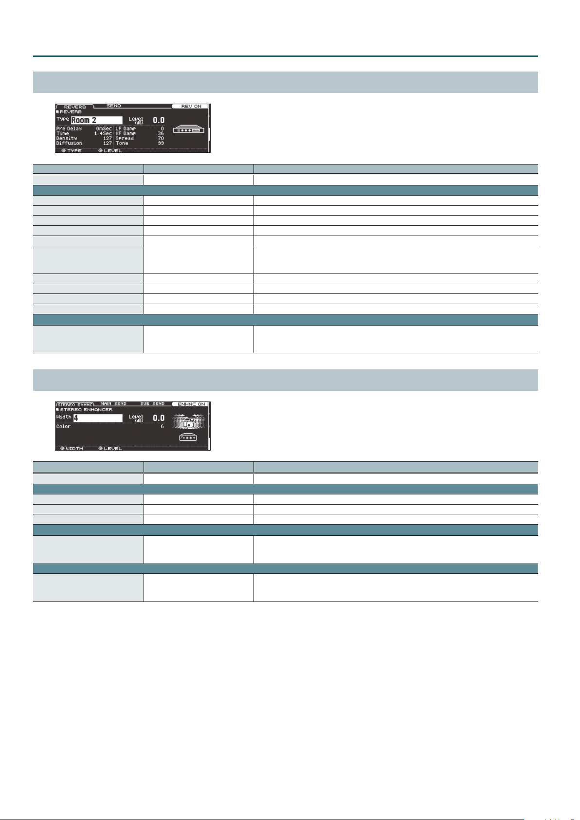
REVERB (page 3)
Parameter Value Explanation
[F4] button OFF, REV ON Turns reverb on/o.
ROOM tab
Type ([R1] knob) ROOM 1, 2, HALL 1, 2, PLATE Type of reverb
Level ([R2] knob) -INF–+6.0 dB Volume of reverb
Pre Delay 0–100 mSec Adjusts the delay time from the direct sound until the reverb sound is heard
Time 0.1–10.0 Sec Time length of reverberation
Density 0–127 Density of reverb sound
Diusion 0–127
LF Damp 0–100 Adjusts the low-frequency region of the reverb sound.
HF Damp 0–100 Adjusts the high-frequency region of the reverb sound.
Spread 0–127 Spread of the reverb sound
Tone 0–127 Tonal character of reverb sound
SEND tab
Reverb Send Volume -INF–+6.0 dB
Change in the density of the reverb sound over time
The higher the value, the denser the sound becomes as time elapses (The eect is more obvious for
longer reverb times).
Amount of reverb applied to each pad
If you press the [F5] (H&R) button to turn it “ON,” you can simultaneously make settings for the head
area and rim area, etc.
STEREO ENHANCER (page 4)
Parameter Value Explanation
[F4] button OFF, ENHNC ON Turns stereo enhancer on/o.
ROOM tab
Width ([R1] knob) MONO, 1–4 Spread of stereo enhancer
Level ([R2] knob) -INF–+6.0 dB Volume of stereo enhancer
Color 1–6 Tonal character of stereo enhancer
MAIN SEND tab
Stereo Enhancer Main Inst Send
SUB SEND tab
Stereo Enhancer Sub Inst Send -INF–+6.0 dB
-INF–+6.0 dB
Amount of stereo enhancer applied to each pad (main instrument)
If you press the [F5] (H&R) button to turn it “ON,” you can simultaneously make settings for the head
area and rim area, etc.
Amount of stereo enhancer applied to each pad (sub-instrument)
If you press the [F5] (H&R) button to turn it “ON,” you can simultaneously make settings for the head
area and rim area, etc.
12
MIXER
1. Press the [MIXER] button.
The MIXER screen appears.
2. Use the PAGE [UP] [DOWN] buttons to access the editing screen.
3. Use cursor buttons to select a parameter, and use the [–] [+] buttons or the dial to edit the value.
4. Press the [KIT] button to return to the DRUM KIT screen.
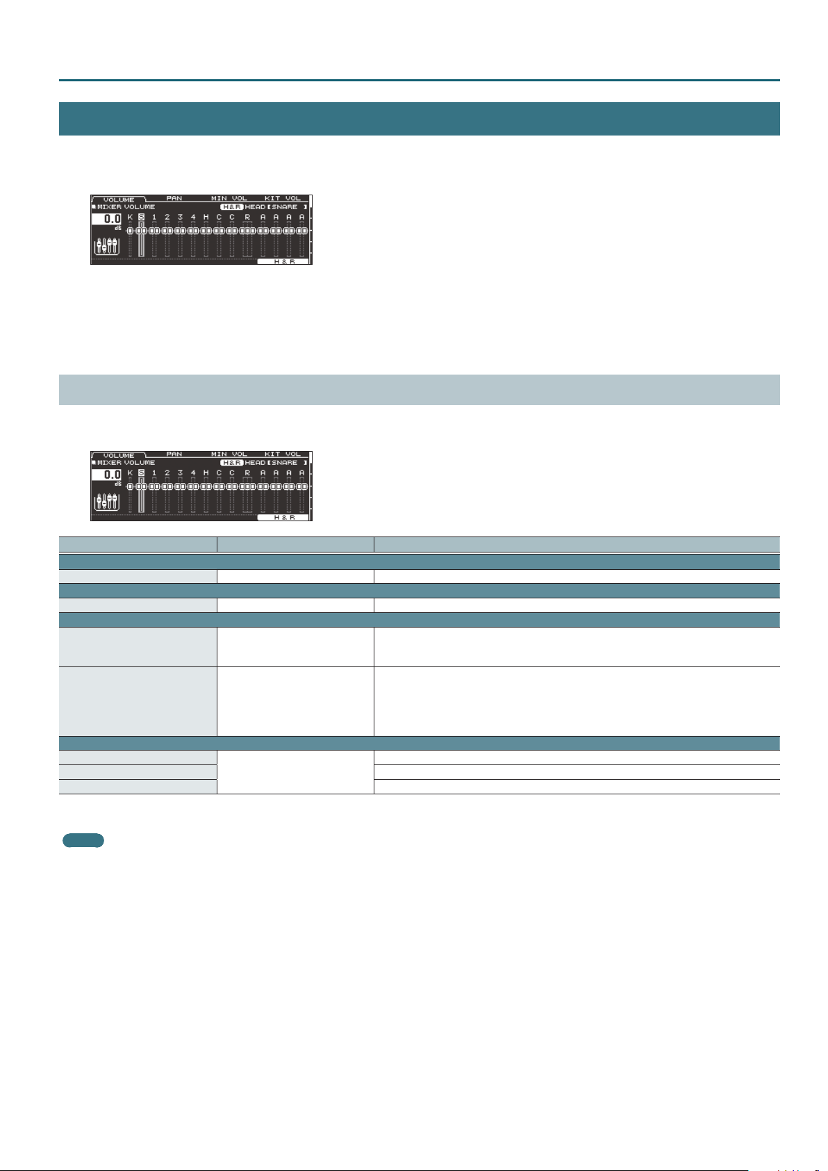
MIXER VOLUME (page 1)
For each drum kit, you can adjust the volume of each pad and adjust the overall volume of the entire drum kit.
You can also adjust how the volume responds to the striking force.
KIT CUSTOMIZE
Parameter Value Explanation
VOLUME tab
Volume -INF–+6.0 dB Volume of each pad
PAN tab
Pan L30–CTR–R30 Stereo position of each pad
MIN VOL tab
Pad Minimum Volume*1 0–15
Pad Maximum Volume*1 -5–0
KIT VOL tab
Kit Volume*2
Pedal HH Volume Pedal hi-hat volume
Xstick Volume Cross-stick volume
*1 Use the cursor [H] [I] buttons to choose whether you’re setting the Pad Minimum Volume or the Pad Maximum Volume.
*2 You can also set “Kit Volume” in the KIT SETTINGS screen (VOLUME tab) (p. 3).
MEMO
If you press the [F5] (H&R) button to turn it “ON,” you can simultaneously make settings for the head area and rim area, etc.
-INF–+6.0 dB
Minimum volume of each pad
This lets you increase the volume of the softest hits while preserving the volume of the strongest
hits. This can make it easier to hear ghost notes on the snare or legato notes on the ride cymbal.
Maximum volume of each pad
This lets you decrease the volume of the strongest hits while preserving their nuances.
You can limit the volume while preserving the nuances of the strongest hits.
* This is available only for pads that support digital connection and for input from the MIDI IN
connector.
Drum kit volume
13
KIT CUSTOMIZE
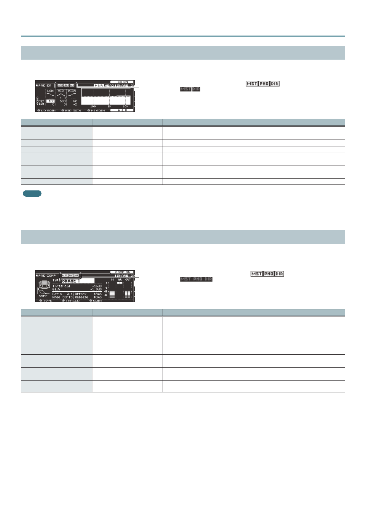
PAD EQ (page 2)
This is a three-band equalizer that each drum kit provides for each strike location of each pad.
You can disable the pad equalizer eect that is output from the DIRECT OUT jacks (p. 29).
This indicates whether the pad equalizer eect is output ( ) from each
jack or is not output ( ).
MST: MASTER OUT jacks
PHO: PHONES jacks (always output)
DIR: DIRECT OUT jacks
Parameter Value Explanation
[F4] button OFF, EQ ON Turns pad equalizer on/o.
Low Freq 20 Hz–1 kHz Center frequency of the low range
Low Gain ([R1] knob) -15–+15 dB Amount of boost/cut for the low range
Mid Freq 20 Hz–16 kHz Center frequency of the mid range
Mid Q 0.5–8.0
Mid Gain ([R2] knob) -15–+15 dB Amount of boost/cut for the mid range
High Freq 1 kHz–16 kHz Center frequency of the high range
High Gain ([R3] knob) -15–+15 dB Amount of boost/cut for the high range
MEMO
If you press the [F5] (H&R) button to turn it “ON,” you can simultaneously make settings for the head area and rim area, etc.
* If the routing setting (p. 29) PadEq/Comp to direct is “OFF,” the pad equalizer eect does not apply to the sound that is output from the DIRECT OUT jacks.
* If the routing setting (p. 29) PadEq/Comp to direct is “OFF,” and Master OUT is set to “DIRECT,” the pad equalizer eect does not apply to the sound that is output from the DIRECT
OUT jacks and MASTER OUT jacks.
Width of the frequency range
A higher Mid Q narrows the aected area.
PAD COMP (page 3)
This is a compressor that each drum kit provides for each pad.
The pad compressor eect can be applied only to the output from the DIRECT OUT jacks. You can also disable the pad compressor eect from being
applied to the PHONES jack output (p. 29).
This indicates whether the pad compressor eect is output ( ) from each
jack or is not output ( ).
MST: MASTER OUT jacks
PHO: PHONES jacks
DIR: DIRECT OUT jacks
Parameter Value Explanation
[F4] button OFF, COMP ON Turns pad compressor on/o.
Type ([R1] knob)
Threshold ([R2] knob) -48–0 dB Volume level at which compression begins
Gain ([R3] knob) -24–+24 dB Output level of the compressor
Ratio 1:1–100:1 Compression ratio
Knee HARD, SOFT1–3 Attack of the sound at the moment compression is applied
Attack 0–100 mSec Time from when the volume goes up the threshold level until the compressor eect applies
Release 10–1000 mSec
* Pad compressor settings are made for individual pads. They cannot be made for individual strike locations (such as the head or rim).
* If the routing setting (p. 29) PadEq/Comp to direct is “OFF,” the pad compressor eect does not apply to the sound that is output from the DIRECT OUT jacks.
* If the routing setting (p. 29) PadEq/Comp to direct is “OFF,” and Master Out is set to “DIRECT,” the pad compressor eect does not apply to the sound that is output from the
DIRECT OUT jacks and the MASTER OUT jacks.
* If the routing setting (p. 29) PadComp to Phones is “OFF,” the pad compressor eect does not apply to the sound that is output from the PHONES jacks.
KICK 1, 2, SNARE1, 2, TOM 1, 2, CYM 1,
2, SOFT, HARD, LIMITER
Character of the compressor
* When you change this parameter, the pad compressor’s parameters Ratio, Knee, Attack, and
Release change to optimal settings for your selection. You can then make further adjustments to
these parameters as necessary.
Time from when the volume falls below the threshold level until the compressor eect no longer
applies
14

Meters shown in the PAD COMP screen
In the PAD COMP screen, the “input meter,” the “gain reduction meter,” and the “output meter” are displayed.
KIT CUSTOMIZE
Input meter
The “input meter”
shows the level (dB)
being input to the pad
compressor.
Output meter
The “output meter” shows the output level
following the pad compressor.
Gain reduction meter
The “gain reduction meter”
shows the change in level
(dB) produced by the pad
compressor.
Adjust the pad compressor’s “Gain” so that the output meter does not exceed 0 dB (i.e., so that it does not clip).
MULTI EFFECT (MFX) (page 4)
You can use three multi-eects simultaneously for each drum kit.
Parameter Value Explanation
MFX tab
[F5] button OFF, MFX1–3 ON Turns on/o the multi-eect 1–3 selected by the [R1] knob.
MFX SEL ([R1] knob) MFX1–3 You can use three multi-eects simultaneously for each drum kit.
Type of multi-eect
Type ([R2] knob)
Level ([R3] knob) -INF–+6.0 dB Volume of the eect sound for the selected multi-eect
ASSIGN tab
MFX Assign MFX1–3 Select the multi-eect 1–3 that is applied to each pad.
SEND tab
MFX Send Volume -INF–+6.0 dB Eect send level for each pad
DRY+MFX tab
MFX DRY+WET*1
*1 MFX DRY+WET is specied for each pad. It cannot be specied for individual strike locations (such as the head or rim).
If MFX DRY+WET is set to “MFX ONLY,” some multi-eect settings might cause no sound to be output.
Reference
For more about multi-eects, refer to “Multi-Eect Parameters” (p. 34).
DRY+MFX The dry sound and eect sound will be output.
MFX ONLY Only the eect sound will be output.
15
 Loading...