

Roland TD-50K2 Data List

Data List
© 2021 Roland Corporation 01

Contents
DRUM KIT .......................................... 4
: DRUM KIT Screen ................................ 4
: KIT SETTINGS .................................... 4
KIT SETTINGS 1 (page 1) ............................. 4
KIT SETTINGS 2 (page 2) ............................. 5
PAD CONTROL (page 3) .............................. 5
PAD MIDI (page 4).................................... 6
KIT CUSTOMIZE ................................... 8
: INSTRUMENT..................................... 8
INSTRUMENT (page 1) ............................... 8
TRANSIENT (page 2).................................. 11
SUB INST (page 3) .................................... 12
: AMBIENCE ........................................ 14
AMBIENCE (page 1) .................................. 14
OVERHEAD (page 2).................................. 14
ROOM (page 3)....................................... 18
: MIXER ............................................. 22
MIXER VOLUME (page 1) ............................. 22
PAD EQ (page 2)...................................... 23
PAD COMP (page 3) .................................. 23
MULTI EFFECT (MFX) (page 4) ......................... 24
MASTER COMP (page 5).............................. 25
MASTER EQ (page 6) ................................. 26
USER SAMPLE ..................................... 28
SAMPLE LIST ....................................... 28
SONG . . . . . . . . . . . . . . . . . . . . . . . . . . . . . . . . . . . . . . . . . . . . . . . . 29
: SONG.............................................. 29
SONG (page 1) ....................................... 29
SONG INFO (page 2) ................................. 29
SET LIST............................................. 30
: SETUP ............................................. 30
CLICK ................................................ 31
: Making the Click Play (Metronome) ............... 31
: Rhythm Training (Coach Mode) .................... 32
Correctly Playing in Time with the Beat (TIME CHECK) 32
Developing Internal Timing Sense (QUIET COUNT).... 33
WARM UPS . . . . . . . . . . . . . . . . . . . . . . . . . . . . . . . . . . . . . . . . . 34
TRIGGER ............................................ 36
: TRIGGER .......................................... 36
TRIG BASIC (page 1) .................................. 36
TRIG ADVANCED (page 2)............................ 39
TRIG MONITOR (page 3).............................. 41
SETUP ............................................... 42
: OUTPUT........................................... 42
PAD OUTPUT (page 1)................................ 42
OTHER OUTPUT (page 2)............................. 43
OUTPUT ROUTING (page 3) .......................... 43
: USB AUDIO ....................................... 45
Conguring the Routing for USB Audio
(Audio Routing) . . . . . . . . . . . . . . . . . . . . . . . . . . . . . . . . . . . . . . . . 46
: OPTION ........................................... 47
: CONTROL ......................................... 48
: MIDI ............................................... 49
: AUTO OFF......................................... 51
: INFO ............................................... 51
Multi-Eect Parameters......................... 52
DELAY .............................................. 53
TAPE ECHO ......................................... 53
REVERSE DELAY .................................... 53
3TAP PAN DELAY ................................... 54
OD0DELAY ....................................... 54
DS0DELAY ....................................... 54
CHORUS............................................ 54
SPACE-D............................................ 54
OD0CHORUS..................................... 55
DS0CHORUS ..................................... 55
PHASER A .......................................... 55
PHASER B .......................................... 55
STEP PHASER....................................... 55
FLANGER........................................... 56
REVERB............................................. 56
LONG REVERB ...................................... 56
SUPER FILTER....................................... 57
FILTER+DRIVE ...................................... 57
AUTO WAH ......................................... 57
OD/DS0TWAH ................................... 58
LOFI COMPRESS.................................... 58
DISTORTION........................................ 58
OVERDRIVE......................................... 58
SATURATOR ........................................ 58
T-SCREAM.......................................... 58
BIT CRUSHER ....................................... 59
ISOLATOR .......................................... 59
RING MODULATOR................................. 59
PITCH SHIFTER ..................................... 59
AUTO PAN.......................................... 60
TIME CTRL DLY ..................................... 60
PAN DELAY . . . . . . . . . . . . . . . . . . . . . . . . . . . . . . . . . . . . . . . . . 60
SDD-320 ........................................... 60
SBF-325 ............................................ 61
SPEAKER SIM ....................................... 61
GUITAR AMP SIM ................................... 62
LOW BOOST........................................ 63
ENHANCER......................................... 63
2

Drum Kit List....................................... 64
Instrument List.................................... 65
Song List............................................ 73
Drum Kit Parameter Structure ................ 74
Block Diagram .................................... 75
Contents
ASIO is a trademark and software of Steinberg Media
Technologies GmbH
Company names and product names appearing in this
document are registered trademarks or trademarks of their
respective owners.
3

DRUM KIT
DRUM KIT Screen
Parameter Value Explanation
Species whether a snare pad produces the cross-stick sound (ON) or not (OFF).
XSTICK OFF, ON
KIT SETTINGS
1. Press the [KIT] button.
2. Press the [F5] (MENU) button.
The menu screen appears.
* If the trigger input of a pad that supports both cross-stick technique and digital
connection (such as the PD-140DS) is assigned to a snare, cross-stick playing is
always possible. In this case, the screen does not show the XSTICK icon.
3. Use the PAGE [UP] [DOWN] buttons to access the editing screen.
4. Use cursor buttons to select a parameter, and use the [–] [+] buttons or the dial to edit the value.
5. Press the [KIT] button to return to the DRUM KIT screen.
KIT SETTINGS 1 (page 1)
Parameter Value Explanation
Edits the name of the drum kit.
[F4] button
VOLUME tab
Kit Volume -INF–+6.0 dB Drum kit volume
Reference
For details on how to assign a name, refer to “Renaming a Drum Kit” in the “Reference Manual” (PDF).
4

Parameter Value Explanation
COLOR tab
1: WHITE
2: RED
3: GREEN
4: BLUE
Kit Color
FAVORITE tab
Favorite OFF, ON Registers (ON)/de-registers (OFF) the drum kit in favorites.
5: PINK
6: PURPLE
7: ORANGE
8: YELLOW
9: EMERALD
10: RAINBOW
Use the [KIT] button or [R1]–[R3] knobs to specify the illumination color.
KIT SETTINGS 2 (page 2)
DRUM KIT
Parameter Value Explanation
BRUSH tab
Brush Switch OFF, ON
KIT TEMPO tab
OFF
Kit Tempo
ON
Tempo 20–260 Tempo specied for each drum kit
FONT tab
Kit Font DEFAULT, TYPE 1–5 Sets how the drum kit name (on the top row) looks (the font) for each drum kit.
Species whether you’re performing with sticks (OFF) or brushes (ON).
If this is “ON,” you can perform by scraping (sweeping) the brushes.
Use a common tempo (p. 31) for the entire TD-50X.
The tempo does not change when you switch drum kits.
Use the tempo that is specied by each drum kit.
The click tempo and the tempo of tempo-synchronized eects can be individually
specied for each drum kit.
PAD CONTROL (page 3)
Parameter Value Explanation
PEDALBEND tab
Species the amount of pitch change that occurs according to the depth to which
Pedal Bend Range -24–0–24
you press the hi-hat pedal.
You can set this for each pad (head and rim separately) in semitone units.
5

DRUM KIT
Parameter Value Explanation
POSITION tab
Turns on/o tonal changes that occur depending on your strike location or the
nuances of your rim shots.
You can set this for the snare (head, rim), tom (head, rim), hi-hat (when using the VH-
Position Control *1 OFF, ON
POS AREA tab
Position Area *1
MUTE GRP tab
MUTE SEND
MUTE RECEIVE
*1: This supports the following trigger inputs.
5 SNARE
5 TOM1–4
5 HI-HAT (only when a VH-14D is assigned to the hi-hat trigger input)
5 The bow (head) of RIDE
5 AUX1–4
* Depending on the pad that is connected or the instrument that is selected, there might be cases in which this has no eect.
INSIDE -5–DEFAULT– OUTSIDE
+5
– (OFF), 1–8
14D), ride (bow), and AUX (head, rim) trigger inputs.
Head: Strike position
Rim: Rim shot nuance
Bow: Strike position, left-right detection (VH-14D only)
Edge: left-right detection ( VH-14D only)
Species the striking area for the head or rim.
“INSIDE” settings make it easier to play notes toward the inside; “OUTSIDE” settings
make it easier to play toward the outside.
Specify the mute group number.
When you strike the pad of the number specied in MUTE SEND, the sound of the
pad assigned to the same number in MUTE RECEIVE is muted.
* Even if you specify the same number in MUTE SEND and MUTE RECEIVE for the
same location (e.g., head or rim) of the same pad, muting does not occur.
PAD MIDI (page 4)
Parameter Value Explanation
NOTE tab
Note No.
GATE tab
Gate Time 0.1– 8.0 s Duration of the note transmitted by each pad
MIDI CH tab
MIDI Channel
0(C -)–127(G 9) MIDI note number transmitted and received by each pad
OFF Note messages are not transmitted or received
CH1–CH16
GLOBAL
MIDI channel on which each pad transmits or receives note messages or control
change messages
Transmitted and received on the transmit/receive channel specied in SETUP (p.
49)
MIDI note numbers transmitted and received by the hi-hat
Item Explanation
HI-HAT OPEN <BOW>
HI-HAT OPEN <EDGE>
HI-HAT CLOSE <BOW>
HI-HAT CLOSE <EDGE>
HI-HAT PEDAL MIDI note number transmitted and received by pedal hi-hat
MIDI note number transmitted and received by open hi-hat (bow, edge)
MIDI note number transmitted and received by closed hi-hat (bow, edge)
6

DRUM KIT
MIDI note numbers transmitted and received by the snare
Parameter Explanation
SNARE <HEAD>
SNARE <RIM>
SNARE <BRUSH> MIDI note number transmitted and received by brush sweep
SNARE <XSTICK> MIDI note number transmitted and received by cross stick
MIDI note number transmitted and received by head shot and rim shot
When setting multiple pads to the same note number
When playing the internal sound generator of the TD-50X, if an incoming note number is assigned to more than one pad, that note plays
the instrument of the pad with the lowest trigger input number. If the same note number is assigned to both the head and the rim, the head
instrument is sounded.
MEMO
An asterisk (*) appears at the right of the note number for trigger inputs that are not sounded.
Example:
Note number “38 (D 2)” is set for the head and rim of trigger input 2 SNARE and the head of trigger input 3 TOM 1. In this case, when note
number 38 (D2) is received, the instrument assigned to the head of trigger input 2 SNARE is played.
About the gate time
Percussion sound modules normally produce sound only in response to “Note on” messages, and ignore “Note o” messages. However
general-purpose sound modules or samplers do receive the note-o messages that are transmitted and respond by turning o the
sound.
Since gate time is normally not necessary for a percussion sound module, this is set to the minimum value when the unit is shipped from
the factory. If a note-o message is received while the sound module has this setting, it is received as an extremely brief note that has
almost no time to be heard, and is nearly inaudible. (Alternatively, it is possible that this could be heard as an unwanted noise.) To avoid
this, specify the note duration of the MIDI performance data that is produced when you strike each pad.
* If the same note number is sounded again in an overlapping manner, a note-o is transmitted before transmitting note-on, even if it is
within the gate time.
7

KIT CUSTOMIZE
INSTRUMENT
1. Press the [INSTRUMENT] button.
The INSTRUMENT screen appears.
2. Select the pad that you want to edit.
3. Use the PAGE [UP] [DOWN] buttons and function buttons to select the item that you want to edit.
* The parameters that you can edit depend on the pad and instrument.
4. Use cursor buttons to select a parameter, and use the [–] [+] buttons or the dial to edit the value.
MEMO
For some parameters, you can also use the rotary knobs to edit the value.
5. Press the [KIT] button to return to the DRUM KIT screen.
INSTRUMENT (page 1)
Parameters that can be edited for each instrument
Parameter Value Explanation
INST tab
Inst
ADVANCED tab
Pad Pitch -4800–4800 Instrument pitch (units of one cent)
Pad Pitch Sweep *1 -100–100
Pad Decay *1 1–100 Length of decay
Dynamic Enhancer Sw *1 OFF, ON
001– (preset)
U001–U500 (user sample)
Instrument number
Reference
For more about instruments, refer to “Instrument List” (p. 65).
After the sound begins, the pitch gradually rises (falls).
Positive (+) values make the pitch start high and then fall; negative (-) values make
the pitch start low and then rise.
Larger values produce greater change.
* In some cases, changing the Pitch setting by a large amount might limit the Pitch
Sweep eect.
Species whether the sense of strong strikes is enhanced (ON) or not enhanced
(OFF).
*1: If a user sample is assigned to the instrument, you can’t specify Dynamic Enhancer Sw. Also, if the user sample’s Play Type (p. 28) is set to “LOOP ALT,”
the Pad Pitch Sweep and Pad Decay have no eect.
MEMO
If you press the [F5] (H&R) button to turn it “ON,” you can simultaneously make settings for the head area and rim area, etc.
8

KICK A/KICK B
* The order shown is for TYPE1 of the V-EDIT layout (p. 47).
Parameter Value Explanation
INST tab
Tuning -100–100 Tuning of the head
Muing
BASIC 1 tab
Shell Depth 1.0–30.0 Depth of the shell
Beater Type FELT1, 2, WOOD, PLASTIC1, 2 Type of beater
Kit Resonance OFF, 1–8 Amount of resonance for the entire drum kit
BASIC 2 tab
Snare Buzz OFF, 1–8 Resonance to the snare
Mic Distance *1 -5–NORMAL–+5 Distance from the mic to the drum
Mic Size *1 NORMAL, LARGE Size of the mic
ADVANCED tab
Head Type CLEAR, COATED, PINSTRIPE Type of head
OFF, TAPE1–4, BLANKET1–3,
WEIGHT1, 2
Muing (muting) setting
KIT CUSTOMIZE
*1: This parameter is disabled for KICK B.
SNARE/CROSS STICK/SNARE BRUSH
* The order shown is for TYPE1 of the V-EDIT layout (p. 47).
Parameter Value Explanation
INST tab
Tuning -100–100 Tuning of the head
Muing OFF, TAPE1–7, DONUT1, 2 Muing (muting) setting
BASIC 1 tab
Shell Depth *1 1.0–30.0 Depth of the shell
Overtone *2 -5–NORMAL–5 Amount of overtone components
Mic Distance *1, *3 -5–NORMAL–+5 Distance from the mic to the snare drum
BASIC 2 tab
Strainer Adj. *3
Wire Type *3 TYPE1–3 Type of strainer
Wire Level *3 -6–NORMAL–+6 Volume of strainer
OFF, LOOSE1–3, MEDIUM1–3,
TIGHT1–3
Tension of the strainer (resonating cords)
9

KIT CUSTOMIZE
Parameter Value Explanation
ADVANCED tab
Head Type *1 CLEAR, COATED, PINSTRIPE Type of head
XStick Inst *4 1–5 Cross-stick sound selection
Cross-stick sound volume
XStick Inst Volume *4 -INF–+6.0 dB
*1: Unavailable if the instrument group is CROSS STICK.
*2: When the instrument group is “SNARE,” this is disabled for some of the instruments. Also, this is disabled when the instrument group is “CROSS STICK” or
“SNARE BRUSH.”
*3: Unavailable if the instrument group is SNARE BRUSH.
*4: Only if the SNARE/CROSS STICK instrument is assigned to the rim of the snare (or to the rim of a digitally connected pad that is assigned to snare)
* PINSTRIPE is a registered trademark of Remo Inc., U.S.A.
MEMO
The “XStick Volume” can also be edited from the MIXER DRUM KIT VOLUME screen
(KIT VOL tab) of the MIXER (p. 22).
TOM/TOM BRUSH
* The order shown is for TYPE1 of the V-EDIT layout (p. 47).
Parameter Value Explanation
INST tab
Tuning -100–100 Tuning of the head
Muing OFF, TAPE1–5, FELT1–4 Muing (muting) setting
BASIC 1 tab
Shell Depth 1.0–30.0 Depth of the shell
Snare Buzz OFF, 1–8 Resonance to the snare
Mic Distance *1 -5–NORMAL–+5 Distance from the mic to the tom
ADVANCED tab
Head Type CLEAR, COATED, PINSTRIPE Type of head
*1: This is disabled for the TOM BRUSH.
HI-HAT/HI-HAT PROC/HI-HAT ELEC
Parameter Value Explanation
INST tab
Size 1.0–40.0 Hi-hat diameter
Thickness THIN-5–STANDARD–THICK +5 Thickness of the hi-hat
BASIC 1 tab
Openness of the hi-hat
If something other than “NORMAL” is selected, the openness of the hi-hat does not
change, regardless of how you press the hi-hat pedal.
10
Fixed
NORMAL, PRESS, CLOSE, HALF1,
HALF2, OPEN

KIT CUSTOMIZE
ADVANCED tab
Volume of pedal hi-hat
Pedal HH Volume -INF–+6.0 dB
MEMO
The closed hi-hat position (Fixed = CLOSE) can be enabled by pressing an optional footswitch or hitting a pad switch. Please refer to “CONTROL” (p. 48).
MEMO
The “Pedal HH Volume” can also be edited from the MIXER DRUM KIT VOLUME
screen (KIT VOL tab) of the MIXER (p. 22).
CRASH/CHINA/SPLASH/STACKED CYMBAL
Parameter Value Explanation
INST tab
Size 1.0–40.0 Cymbal diameter
Thickness THIN-5–STANDARD–THICK +5 Thickness of the cymbal
BASIC 1 tab
Muing OFF, TAPE1–19 Muing (muting) setting
Sizzle Type OFF, RIVET, CHAIN, BEADS Type of sizzle
Sizzle Amount -3–+3 Amount of sizzle
BASIC 2 tab
Low Cut *1 OFF, HALF, FULL Volume of low-frequency sound
*1: For some instruments, these settings are not available.
RIDE
Parameter Value Explanation
INST tab
Size 1.0–40.0 Cymbal diameter
Thickness
BASIC 1 tab
Muing OFF, TAPE1–19 Muing (muting) setting
Sizzle Type OFF, RIVET, CHAIN, BEADS Type of sizzle
Sizzle Amount -3–+3 Amount of sizzle
BASIC 2 tab
Ping Color *1
Ping Level *1 -4–NORMAL–+5 Volume of the ride’s ping sound
Low Cut *1 OFF, HALF, FULL Volume of low-frequency sound
THIN-5–STANDARD–
THICK +5
LIGHT2, 1, STANDARD, HEAVY1,
2
Thickness of the cymbal
Tonal character of the ride’s ping sound
*1: For some instruments, these settings are not available.
TRANSIENT (page 2)
You can adjust the attack and release (transient) for each instrument.
* You may not be able to congure these for certain instrument or user sample settings.
11

KIT CUSTOMIZE
Parameter Value Explanation
[F4] button OFF, TRANSIENT ON Turns the transient eect on/o.
Type PRESET, TYPE 1–4
This lets you set the eects when the transient is applied to a user sample. (For the
built-in sounds, “(PRESET)” is shown—these cannot be edited.)
Attack Time ([R1] knob) 1–100 Time over which the attack changes
Attack Depth ([R2] knob) -100–+100 Adjustment of the attack
For the NORMAL setting, the transient attack eect is always applied.
Attack Type
NORMAL, WIDE 1,
WIDE 2
For the WIDE 1/2 setting, the attack eect becomes weaker when you strike the pad
more softly. This is eective when you want to soften the attack on the transients,
such as when striking the snare drum softly.
Release Depth ([R3] knob) -100–100 Adjustment of the release
Gain -12.0–+6.0 dB Volume following transient adjustment
SUB INST (page 3)
Parameter Value Explanation
[F4] button OFF, SUB ON Turns the sub-instrument on/o.
SUB INST tab
Sub-instrument number
Reference
For more about instruments, refer to “Instrument List” (p. 65).
SUB INST
001– (preset)
U001–U500 (user sample)
These parameters specify how the sub-instrument will be sounded.
Volume
The main instrument (A) and sub-instrument (B) always sound
together as a layer.
The sub-instrument (B) is added as a layer only if the strike is
stronger than “Fade Point.”
If the strike is stronger than “Fade Point,” the sub-instrument
(B) is added as a layer according to the strength of that strike.
The main instrument (A) and sub-instrument (B) are the same
volume at the Fade End point.
Layer Type
MIX
FADE1
FADE2
Volume
Volume
Volume
Playing
Dynamics
Playing
Dynamics
Playing
Dynamics
This basically works the same as FADE2, but the main
XFADE
Playing
Dynamics
instrument (A) sounds quieter when you strike the pad
stronger than the Fade Point up to Fade End.
Layer Type SWITCH
12
Volume
Playing
Dynamics
Strikes weaker than “Fade Point” sound the main instrument
(A), and strikes stronger than “Fade Point” switch to sound the
sub-instrument (B).s

KIT CUSTOMIZE
Species the force of the strike at which the sub-instrument begins to be sounded.
If this is “1,” the sub-instrument is sounded by a strike of any force.
Fade Point *1
Fade End *1 Sets the fade or crossfade range when the Layer Type is “FADE2” or “XFADE.”
Sub Volume -INF–+6.0 dB Volume of the sub-instrument
EDIT tab
Reference
For details on the parameters that can be edited, refer to “INSTRUMENT (page 1)” (p. 8).
SUB TRNSNT (TRANSIENT) tab * You may not be able to congure these for certain instrument or user sample settings.
Transient Switch OFF, TRANSIENT ON Transient on/o
Transient Type PRESET, TYPE 1–4
Attack Time 1–100 Time over which the attack changes
Attack Depth -100–+100 Adjustment of the attack
Attack Type
Release Depth -100–100 Adjustment of the release
Gain -12.0–+6.0 dB Volume following transient adjustment
If this is “127” (“127+32” for a pad that supports digital connection), the sub-instrument is sounded only by the
strongest strike.
* This is not available if Layer Type is “MIX.”
This lets you set the eects when the transient is applied to a user sample. (For the
built-in sounds, “(PRESET)” is shown—these cannot be edited.)
For the NORMAL setting, the transient attack eect is always applied.
NORMAL, WIDE 1,
WIDE 2
For the WIDE 1/2 setting, the attack eect becomes weaker when you strike the pad
more softly. This is eective when you want to soften the attack on the transients,
such as when striking the snare drum softly.
*1: The Fade Point cannot be set higher than the Fade End.
13
KIT CUSTOMIZE
AMBIENCE
1. Press the [AMBIENCE] button.
The AMBIENCE screen appears.
2. Use the PAGE [UP] [DOWN] buttons to access the editing screen.
3. Use cursor buttons to select a parameter, and use the [–] [+] buttons or the dial to edit the value.
4. Press the [KIT] button to return to the DRUM KIT screen.
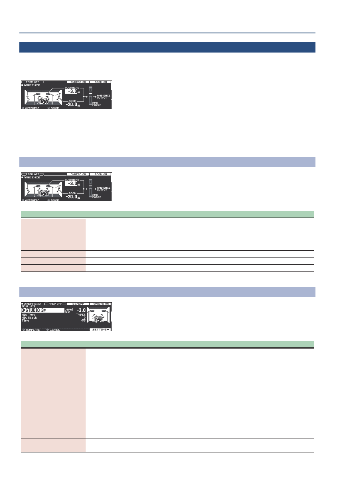
AMBIENCE (page 1)
Parameter Value Explanation
This lets you momentarily hear just the ambience sound through the MASTER OUT
[F1] button PREV OFF, AMB ONLY
[F3] button
[F4] button ROOM OFF, ROOM ON Turns the room ambience eect on/o.
OVERHEAD ([R1] knob) -INF–+6.0dB Volume of overhead
ROOM ([R2] knob) -INF–+6.0dB Volume of room ambience
OVHEAD OFF,
OVHEAD ON
and PHONES jacks
(only when MASTER DIRECT for the MASTER OUT jacks is set to “NORMAL”).
Turns the overhead eect on/o.
OVERHEAD (page 2)
Parameter Value Explanation
When you edit this parameter, all of the overhead settings (except for Level) and
each pad’s input lter selection and send amount will change to the optimal
STUDIO 1–3,
SMALL CLUB 1–2,
TEMPLATE ([R1] knob)
Level ([R2] knob) -INF–+12.0dB Volume of overhead
Mic Type *1 TYPE1–14 Type of mic
Mic Width *1 0–2 Distance between mics
Time *1 -64–0 Overhead reverberation time
RECORDING 1–3,
ROOM 1–3,
STAGE 1–3,
HALL 1–2
settings.
To quickly obtain the sound you want, select the desired template and then edit the
settings.
Depending on the settings of each parameter, the template name might not match
the eect. Also, if the default settings of the template do not match the current
values, an “*” is shown for the template setting.
If you attempt to change the template when the “*” is shown, a message indicates
that the current values will be discarded in order to apply the values of the template.
If you want to discard the current values and apply the values of the template,
choose “OK” and press the [ENTER] button.
14

Parameter Value Explanation
This lets you momentarily hear just the ambience sound through the MASTER OUT
[F2] button PREV OFF, AMB ONLY
[F3] button — Switches to SEND screen
[F4] button OFF, OVHEAD ON Turns the overhead eect on/o.
[F5] button — Switches to the respective SETTING screen
*1: This can also be edited from the MIC SETTING items.
and PHONES jacks
(only when MASTER DIRECT for the MASTER OUT jacks is set to “NORMAL”).
SEND
KIT CUSTOMIZE
OVERHEAD SEND screen
Parameter Value Explanation
[F1] button (SEND tab)
OVERHEAD SEND -INF–+6.0dB Depth of overhead for each pad
[F4] button OFF, OVHEAD ON Turns the overhead eect on/o.
[F5] button (H & R) H&R OFF, H&R ON
[F2] button (FILTER tab)
Settings for the lter in the
previous stage:
THRU, HICUT, LOCUT, PKG
Type
Settings for the lter in the
following stage:
THRU, LPF, HPF, LSF, HSF
Q *1 0.5–8.0
Freq *2 20Hz–16kHz Center frequency
Gain *3 -40.0–15.0dB Amount of boost/cut
[F4] button OFF, OVHEAD ON Turns the overhead eect on/o.
OVERHEAD FILTER SETTING screen
Species whether head and rim of instruments are selected as a set (ON) or
independently (OFF).
Overhead input lter type
The sound sent to the overheads can be passed through a lter. There are two lters
connected in series, one in the previous stage and one in the following stage in the
signal chain. The selectable settings are dierent for each.
You can choose from one through four. By using a lter, you can input the kick,
snare, toms, and cymbals into the overhead mics with the low-frequency and highfrequency regions adjusted individually for each instrument.
THRU
HICUT
LOCUT
PKG
LPF
HPF
LSF
HSF
Width of the frequency range
A higher Q narrows the aected area.
Sends the unaltered input sound through the lter in the following
stage, or to the overhead.
Cuts the frequency region above the base frequency and sends the
sound to the lter in the following stage. The Q can be adjusted.
Cuts the frequency region below the base frequency and sends the
sound to the lter in the following stage. The Q can be adjusted.
Boosts or cuts the frequency region around the base frequency, and
sends the sound to the lter in the following stage. The Q can be
adjusted.
Cuts the frequency region above the base frequency, and sends
the sound to the overheads.
Cuts the frequency region below the base frequency and sends
the sound to the overheads.
Boosts or attenuates the frequency region below the cuto
frequency and sends the sound to the overheads.
Boosts or attenuates the frequency region above the cuto
frequency and sends the sound to the overheads.
OVERHEAD FILTER ASSIGN screen
15

KIT CUSTOMIZE
Parameter Value Explanation
[F3] button (ASSIGN tab)
Overhead input lter selection for each pad
OVERHEAD FILTER ASSIGN BYPASS, 1–4
[F4] button OFF, OVHEAD ON Turns the overhead eect on/o.
[F5] button (H & R) H&R OFF, H&R ON
*1: Only for the lter in the previous stage. This can be set only when Type is HICUT, LOCUT or PKG.
*2: This cannot be set when Type is THRU.
*3: This can be set only when Type is LSF, HSF, or PKG.
BYPASS
1–4 The sound is sent to the specied input lter.
Species whether head and rim of instruments are selected as a set (ON) or
independently (OFF).
The input lter is not used; the sound is sent directly to the
overheads.
SETTING
Turn the [R3] knob to move to settings such as SEND/FILTER and LIMITER.
This can also be adjusted on the SEND screen (p. 15).
PAD SEND LEVEL/FILTER
Here you can specify how the overhead applies for each pad.
Parameter Value Explanation
Overhead input lter selection for each pad
Pad Filter Select BYPASS, 1–4
Pad Send Level -INF–+6.0dB Depth of overhead for each pad
[F2] button PREV OFF, AMB ONLY
[F4] button OFF, OVHEAD ON Turns the overhead eect on/o.
[F5] button (H & R) H&R OFF, H&R ON
BYPASS
1–4 The sound is sent to the specied input lter.
This lets you momentarily hear just the ambience sound through the MASTER OUT
and PHONES jacks
(only when MASTER DIRECT for the MASTER OUT jacks is set to “NORMAL”).
Species whether head and rim of instruments are selected as a set (ON) or
independently (OFF).
The input lter is not used; the sound is sent directly to the
overheads.
PRE COMP
This is a compressor applied before the sound is input to the overhead.
Parameter Value Explanation
Pre Comp Switch OFF, ON
Gain -24.0–+24.0dB Output volume of the pre limiter
Threshold -60–0dB Volume level at which compression begins
Ratio 1:1–100:1 Compression ratio
Knee HARD, SOFT1–3 Attack of the sound at the moment compression is applied
Attack 0.1–100mSec
Release 10–1000mSec
Turns the pre limiter on/o.
(This can also be set with the [F5] button.)
Time from when the volume goes up the threshold level until the compressor eect
applies
Time from when the volume falls below the threshold level until the compressor
eect no longer applies
16

Parameter Value Explanation
This lets you momentarily hear just the ambience sound through the MASTER OUT
[F2] button PREV OFF, AMB ONLY
[F4] button OFF, OVHEAD ON Turns the overhead eect on/o.
and PHONES jacks
(only when MASTER DIRECT for the MASTER OUT jacks is set to “NORMAL”).
MIC SETTING
These are the overhead mic settings.
Parameter Value Explanation
Mic Type *1 TYPE1–14 Type of mic
Mic Width *1 0–2 Distance between mics
Time *1 -64–0 Overhead reverberation time
Distance 0–6 Distance between the mics and the performer
Output Width DEFAULT, WIDE+1–+6 Sense of space for the overhead sound
This lets you momentarily hear just the ambience sound through the MASTER OUT
[F2] button PREV OFF, AMB ONLY
[F4] button OFF, OVHEAD ON Turns the overhead eect on/o.
and PHONES jacks
(only when MASTER DIRECT for the MASTER OUT jacks is set to “NORMAL”).
KIT CUSTOMIZE
MEMO
You can reset all of the MIC SETTING values to their defaults by pressing the [F5] (MIC RESET) button.
*1: This can also be set using the parameters in ““OVERHEAD (page 2)” (p. 14).
EQ
These are the overhead EQ settings.
Parameter Value Explanation
Switches the EQ mode.
STEREO: Adjusts the input sound so that the tonal character is the same on the left
and right sides.
MID/SIDE: Adjusts the input sounds at the center of the stereo eld (MID) and the
sounds at the left-right sides of the stereo eld (SIDE) separately. The respective Q,
MODE STEREO, MID/SIDE
Freq and Gain setting values are common for the MID side of the STEREO and MID/
SIDE EQ modes.
STEREO MID/SIDE
Low Frequency 20–16k (Hz) Center frequency of the low range
Low Gain -40.0–+15.0 (dB) Amount of low-range boost/cut
Mid Frequency 20–16k (Hz) Center frequency of the middle range
Mid Q 0.5–8.0
Mid Gain -40.0–+15.0dB (dB) Amount of mid-range boost/cut
High Frequency 20–16k (Hz) Center frequency of the high range
Adjusts the width of the frequency band.
Higher values make the width narrower.
17

KIT CUSTOMIZE
Parameter Value Explanation
High Gain -40.0–+15.0 (dB) Amount of high-range boost/cut
This lets you momentarily hear just the ambience sound through the MASTER OUT
[F2] button PREV OFF, AMB ONLY
[F4] button OFF, OVHEAD ON Turns the overhead eect on/o.
MEMO
You can reset all of the EQ values to their defaults by pressing the [F5] (EQ RESET) button.
and PHONES jacks
(only when MASTER DIRECT for the MASTER OUT jacks is set to “NORMAL”).
POST COMP
Parameter Value Explanation
Post Comp Switch OFF, ON Turns the Post Comp on/o (this can also be set using the [F5] button).
Gain -24.0–+24.0dB Output volume of the post comp
Threshold -60–0dB Volume level at which compression begins
Ratio 1: 1–100: 1 Compression ratio
Knee HARD, SOFT1–3 Attack of the sound at the moment compression is applied
Attack 0.1–100mSec
Release 10–1000mSec
[F2] button PREV OFF, AMB ONLY
[F4] button OFF, OVHEAD ON Turns the overhead eect on/o.
Time from when the volume goes up the threshold level until the compressor eect
applies
Time from when the volume falls below the threshold level until the compressor
eect no longer applies
This lets you momentarily hear just the ambience sound through the MASTER OUT
and PHONES jacks
(only when MASTER DIRECT for the MASTER OUT jacks is set to “NORMAL”).
ROOM (page 3)
Here you can apply either Room ambience or reverb eects to the drum kit.
Common parameters
Parameter Value Explanation
[F4] button (OFF, ROOM ON) OFF, ROOM ON Turns the room eect on/o.
[F1] button (ROOM tab)
ROOM, REVERB, TD-50 ROOM,
Type ([R1] knob)
Level ([R2] knob) -INF–+6.0dB Volume of reverb
[F2] button (SEND tab)
Room Send Volume -INF–+6.0dB Amount of room applied to each pad
[F5] button (H & R) H&R OFF, H&R ON
[F3] button
WARM HALL, SRV-2000,
SRV-2000(NLR)
Type of room reverberation
Select your desired reverberation.
Species whether head and rim of instruments are selected as a set (ON) or
independently (OFF).
18

Parameter Value Explanation
This lets you momentarily hear just the ambience sound through the MASTER OUT
[F3] button PREV OFF, AMB ONLY
and PHONES jacks
(only when MASTER DIRECT for the MASTER OUT jacks is set to “NORMAL”).
Specic parameters
ROOM
Parameter Value Explanation
SMALL STUDIO 1–4,
LARGE STUDIO 1–4,
Room Type
Distance 0–6 Sense of distance for the room's reverberation
Time -64–0 Reverberation time of the room
LIVE HOUSE 1–4,
STAGE 1–4,
SMALL HALL 1–4,
MIDDLE HALL 1–4
Type of room
KIT CUSTOMIZE
REVERB
Parameter Value Explanation
Reverb Type ROOM 1, 2, HALL 1, 2, PLATE Type of reverb
Pre Delay 0–100mSec Adjusts the delay time from the direct sound until the reverb sound is heard.
Time 0.1–10.0Sec Time length of reverberation
Density 0–127 Density of reverb sound
Change in the density of the reverb sound over time
Diusion 0–127
LF Damp 0–100 Adjusts the low-frequency region of the reverb sound.
HF Damp 0–100 Adjusts the high-frequency region of the reverb sound.
Spread 0–127 Spread of the reverb sound
Tone 0–127 Tonal character of reverb sound
The higher the value, the denser the sound becomes as time elapses (The eect is
more obvious for longer reverb times).
19

KIT CUSTOMIZE
TD-50 ROOM
Parameter Value Explanation
BEACH, LIVING ROOM, BATH
ROOM, STUDIO, GARAGE,
LOCKER ROOM, THEATER, CAVE,
GYMNASIUM, DOME STADIUM,
Room Type
Room Size
Room Shape 0–100 Room shape and reverberation length
Wall Type
Mic Position
BOOTH A, BOOTH B, STUDIO
A, STUDIO B, BASEMENT, JAZZ
CLUB, ROCK CLUB, BALLROOM,
GATE, CONCERT HALL, SPORTS
ARENA, EXPO HALL, BOTTLE,
CITY, SPIRAL
TINY, SMALL, MEDIUM, LARGE,
HUGE
CURTAIN, CLOTH, WOOD,
PLASTER, CONCRETE, GLASS
NEXT DOOR, LOW FLOOR, LOW,
MID LOW, MID, MID HIGH, HIGH,
CEILING A, CEILING B
Type of room reverberation
Size of the room
Wall material
Tonal change caused by mic position
WARM HALL
Parameter Value Explanation
Pre Delay 0.0–100.0 [msec] Adjusts the delay time from the direct sound until the reverb sound is heard.
Time 0.3–30.0 [sec] Adjusts the decay length of the reverb sound.
Pre LPF 16–15000 [Hz], BYPASS
Pre HPF BYPASS, 16–15000 [Hz]
PreLoop LPF 16–15000 [Hz], BYPASS
Diusion 0–127 Adjusts the change in the density of the reverb over time.
HF Damp Freq 1000–8000 [Hz] Adjusts the frequency above which to cut the high-frequency portion of the reverb.
HF Damp Ratio 0.1–1.0 Adjusts the amount by which to attenuate the high-frequency portion of the reverb.
Frequency above which to cut the high-frequency portion of the sound entering
the reverb
Frequency below which to cut the low-frequency portion of the sound entering the
reverb
Frequency above which to cut the high-frequency portion of the extended
reverberation
20

KIT CUSTOMIZE
SRV-2000
Parameter Value Explanation
Selects the type of reverb oered by the Roland SRV-2000 digital reverb.
R37–R0.3: Room reverb.
Selection
Pre Delay 0–160 Adjusts the delay time from the direct sound until the reverb sound is heard.
Time 0.1–99.0 [sec] Adjusts the decay length of the reverb sound.
HF Damp 0.05–1.00 Adjusts the high-frequency portion of the reverb.
Density 0–9 Adjusts the density of the late reverberation.
Attack Gain 0–9 Adjusts the gain of the early reections.
Attack Time 0–9 Adjusts the time of the early reections.
ER Density 0–9 Adjusts the density of the early reections.
ER Level 0–99 Adjusts the volume of the early reections.
EQ Low Freq 0.04–1.00 [kHz] Frequency of the low range.
EQ Low Gain -24–+12 [dB] Gain of the low range.
EQ Mid Freq 0.25–9.99 [kHz] Frequency of the middle range.
EQ Mid Gain -24–+12 [dB] Gain of the middle range.
EQ Mid Q 0.2–9.0
EQ Hi Freq 0.80–9.99 [kHz] Frequency of the high range.
EQ Hi Gain -24–+12 [dB] Gain of the high range.
EQ Hi Q 0.2–9.0
R0.3, R1.0, R7.0, R15, R22, R26,
R32, R37, H15, H22, H26, H32,
H37, P-B, P-A
H37–H15: Hall reverb.
P-B: Plate reverb.
P-A: Plate reverb.
Width of the middle range.
Set a higher value to narrow the range to be aected.
Species the width of the high-frequency range.
Set a higher value to narrow the range to be aected.
Higher values increase the size of the room.
Higher values increase the size of the concert hall.
A more amboyant reverb sound than P-A.
SRV-2000(NLR)
Parameter Value Explanation
Pre Delay 0–120 Adjusts the delay time from the direct sound until the reverb sound is heard.
Reverb Time -0.9–+99.0 [sec] Adjusts the decay length of the reverb sound.
Gate Time 10–450 [msec]
EQ Low Freq 0.04–1.00 [kHz] Frequency of the low range.
EQ Low Gain -24–+12 [dB] Gain of the low range.
EQ Mid Freq 0.25–9.99 [kHz] Frequency of the middle range.
EQ Mid Gain -24–+12 [dB] Gain of the middle range.
EQ Mid Q 0.2–9.0
EQ Hi Freq 0.80–9.99 [kHz] Frequency of the high range.
EQ Hi Gain -24–+12 [dB] Gain of the high range
EQ Hi Q 0.2–9.0
Adjusts the time from when the reverb starts being heard until the reverb sound is
cut o.
Width of the middle range.
Set a higher value to narrow the range to be aected.
Species the width of the high-frequency range.
Set a higher value to narrow the range to be aected.
21

KIT CUSTOMIZE
MIXER
1. Press the [MIXER] button.
The MIXER screen appears.
2. Use the PAGE [UP] [DOWN] buttons to access the editing screen.
3. Use cursor buttons to select a parameter, and use the [–] [+] buttons or the dial to edit the value.
4. Press the [KIT] button to return to the DRUM KIT screen.
MIXER VOLUME (page 1)
For each drum kit, you can adjust the volume of each pad and adjust the overall volume of the entire drum kit.
You can also adjust how the volume responds to the striking force.
Parameter Value Explanation
VOLUME tab
Volume -INF–+6.0 dB Volume of each pad
PAN tab
Pan L30–CTR–R30 Stereo position of each pad
MIN VOL tab
Minimum volume of each pad
Pad Minimum Volume *1 0–15
Pad Maximum Volume *1 -5–0
KIT VOL tab
Kit (Kit Volume) *2
Pedal HH (Pedal HI-HAT
Volume)
XStick (Xstick Volume) Cross-stick volume
HH Op/Cl Balance -5–+5
-INF–+6.0 dB
This lets you increase the volume of the softest hits while preserving the volume of
the strongest hits. This can make it easier to hear ghost notes on the snare or legato
notes on the ride cymbal.
Maximum volume of each pad
This lets you decrease the volume of the strongest hits while preserving their
nuances.
You can limit the volume while preserving the nuances of the strongest hits.
* This is available only for pads that support digital connection and for input from
the MIDI IN connector.
Drum kit volume
Pedal hi-hat volume
Balance between open and close volume
Lower values decrease the volume of the hi-hat when played while open, relative to
the volume when played while closed. Higher values increase the volume of the hihat when played while open, relative to the volume when played while closed.
*1: Use the cursor [H] [I] buttons to choose whether you’re setting the Pad Minimum Volume or the Pad Maximum Volume.
*2: You can also set “Kit Volume” in the KIT SETTINGS screen (VOLUME tab) (p. 4).
MEMO
If you press the [F5] (H&R) button to turn it “ON,” you can simultaneously make settings for the head area and rim area, etc.
22

PAD EQ (page 2)
This is a three-band equalizer that each drum kit provides for each strike location of each pad.
You can disable the pad equalizer eect that is output from the DIRECT OUT jacks (p. 43).
This indicates whether the pad equalizer eect is output ( ) from
each jack or is not output ( ).
MST: MASTER OUT jacks
PHO: PHONES jacks (always output)
DIR: DIRECT OUT jacks
Parameter Value Explanation
[F4] button OFF, EQ ON Turns pad equalizer on/o.
Low Freq 20 Hz–1 kHz Center frequency of the low range
Low Gain ([R1] knob) -15–+15 dB Amount of boost/cut for the low range
Mid Freq 20 Hz–16 kHz Center frequency of the mid range
Mid Q 0.5–8.0
Mid Gain ([R2] knob) -15–+15 dB Amount of boost/cut for the mid range
High Freq 1 kHz–16 kHz Center frequency of the high range
High Gain ([R3] knob) -15–+15 dB Amount of boost/cut for the high range
Width of the frequency range
A higher Mid Q narrows the aected area.
KIT CUSTOMIZE
MEMO
If you press the [F5] (H&R) button to turn it “ON,” you can simultaneously make settings for the head area and rim area, etc.
* If the routing setting (p. 43) PadEq/Comp to direct is “OFF,” the pad equalizer eect does not apply to the sound that is output from the DIRECT OUT
jacks.
* If the routing setting (p. 43) PadEq/Comp to direct is “OFF,” and Master OUT is set to “DIRECT,” the pad equalizer eect does not apply to the sound that is
output from the DIRECT OUT jacks and MASTER OUT jacks.
PAD COMP (page 3)
This is a compressor that each drum kit provides for each pad.
The pad compressor eect can be applied only to the output from the DIRECT OUT jacks. You can also disable the pad compressor eect from
being applied to the PHONES jack output (p. 43).
This indicates whether the pad compressor eect is output ( ) from
each jack or is not output ( ).
MST: MASTER OUT jacks
PHO: PHONES jacks
DIR: DIRECT OUT jacks
Parameter Value Explanation
[F4] button OFF, COMP ON Turns pad compressor on/o.
KICK 1, 2, SNARE1, 2, TOM 1, 2,
Type ([R1] knob)
Threshold ([R2] knob) -48–0 dB Volume level at which compression begins
Gain ([R3] knob) -24–+24 dB Output level of the compressor
Ratio 1:1–100:1 Compression ratio
Knee HARD, SOFT1–3 Attack of the sound at the moment compression is applied
Attack 0.1–100 mS
Release 10–1000 mS
CYM 1, 2, SOFT COMP,
HARD COMP, LIMITER
Character of the compressor
* When you change this parameter, the pad compressor’s parameters Ratio, Knee,
Attack, and Release change to optimal settings for your selection. You can then
make further adjustments to these parameters as necessary.
Time from when the volume goes up the threshold level until the compressor eect
applies
Time from when the volume falls below the threshold level until the compressor
eect no longer applies
* Pad compressor settings are made for individual pads. They cannot be made for individual strike locations (such as the head or rim).
* If the routing setting (p. 43) PadEq/Comp to direct is “OFF,” the pad compressor eect does not apply to the sound that is output from the DIRECT OUT
jacks.
* If the routing setting (p. 43) PadEq/Comp to direct is “OFF,” and Master Out is set to “DIRECT,” the pad compressor eect does not apply to the sound that
is output from the DIRECT OUT jacks and the MASTER OUT jacks.
23
 Loading...