

Page 1
Setup Guide
Before using this unit, carefully read “USING THE UNIT SAFELY” and “IMPORTANT NOTES” (the leaet “USING THE UNIT SAFELY,” “TD-1 Owner’s Manual,” and the Setup Guide). After reading, keep the document(s)
where it will be available for immediate reference.
© 2018 Roland Corporation
01
02
Check the included items
As soon as you open the package, check to see that all items are included. If anything is missing, please contact your dealer.
* This package does not include a kick pedal. Use with a commercially available kick pedal.
Stand
2
1
3 4 5 10
9
6
7
8
11
12
No. Name Quantity
1 Stand 1
2 Curved pipe 2
3 Straight pipe L (Long) 1
4 Straight pipe R (Short) 1
5 Snare pipe 1
6 Mount holder 3
7 Pad mount 3
8 Pad mount (with the memory clamp) 1
9 Cymbal mount (Short) 2
10 Cymbal mount (Long) 1
11 Cable clip 4
12 Cable tie 2
Assemble the drum stand
* If you will be using this drum stand for an extended period of time in the same location, we recommend that you use a
drum mat (TDM series) made by Roland to prevent the rubber feet from soiling the surface on which they are placed.
Drum sound module/Pads/Others
* The PDX-6A is a new unit designed
specically for the TD-1DMK.
It does not support the use of the
8 Hi-hat control
pedal
8 Drum sound
module holder
NOTE
5 When setting-up or adjusting the stand, take care not to pinch your ngers between movable parts and the main unit. If using this in a location where children are present, be sure
to provide adult supervision or guidance.
5 Prepare an area in which you can perform the assembly safely.
5 Do not use a power tool (e.g., an electric screwdriver) to assemble the stand. You risk damaging or stripping the screws.
8 Kick pad 8 V-Pad for snare
8 Pedal plate 8 Mount holder
8 Cymbal pad for hi-hat/crash/ride
(CY-5 x 3)
(for the pedal plate)
8 Drum sound
module (TD-1)
(PDX-8)
8 Connection
cable
8 V-Pad for tom
(PDX-6A x 3)
8 AC adaptor
rim-shot technique.
8 Setup Guide (this document)
8 Owner’s manual set
8 Drum key
Attaching the parts for the kick
1.
1–1. Remove the cap that is attached to the stand’s
right pipe (with one holder).
1–2. Insert the kick pad and mount holder (for the
pedal plate), and provisionally fasten them in
the orientation shown in the illustration.
Kick pad
Wide Narrow
Mount holder
(for the pedal plate)
Cap
1–3. Replace the cap.
1–4. Attach the pedal plate to the mount holder.
Pedal plate
Assembling the left and right arm sections
2.
Lay the left and right arm sections on the oor while
assembling them.
Left arm section
2–1. Using a drum key, loosen the bolt on the
holder of straight pipe “L” (long), then insert
curved pipe.
Guide hole
Holder
Curved pipe
Bolt
Straight pipe L
(Long)
2
3
As a general rule, insert curved pipe until the
guide hole on the pipe can be seen through the
gap in the holder.
After rmly inserting it all the way, use the
drum key to rmly tighten bolt.
2–2. Use the drum key to loosen the bolt of the
drum sound module holder, then attach the
drum sound module holder to straight pipe
“L” (long) and tighten the bolt.
Drum sound module
holder
Bolt
Straight pipe L
(Long)
3
Right arm section
2–3. Using a drum key, loosen the bolt on the
holder of straight pipe “R” (short) then insert
curved pipe.
Holder
Curved pipe
Guide hole
2
As a general rule, insert curved pipe until the
guide hole on the pipe can be seen through the
gap in the holder.
After rmly inserting it all the way, use the
drum key to rmly tighten bolt.
7 cm
Bolt
Straight pipe R
(Short)
4
Attach the left and right arm sections to
3.
the main unit
3–1. Use a drum key to loosen bolt of the holder
“A” (attached to the left-side pipe (with two
holders) of the stand), and insert left arm
(of the assembly you created in step 2) into
holder “A” of the stand.
Stand
Curved pipe
1
7 cm
Holder B
2
Bolt
Left arm
Curved pipe
Bolt
2
Holder A
As a general rule, insert curved pipe until the
guide hole on the pipe can be seen through the
gap in the holder.
After rmly inserting it all the way, use the
drum key to rmly tighten bolt.
Bolt
Guide hole
3–2. Lower the holder “B” attached to the stand’s
right pipe, moving it down to the position
shown in the illustration.
3–3. Use the drum key to loosen bolt of the holder
“B,” and insert right arm (of the assembly you
created in step 2) into holder “B” of the stand.
Bolt
Holder B
As a general rule, insert curved pipe until the
guide hole on the pipe can be seen through the
gap in the holder.
After rmly inserting it all the way, use the
drum key to rmly tighten bolt.
Right arm
Guide hole
Attaching the snare pipe
4.
4–1. Use the drum key to loosen bolt of the holder
“C,” and insert the snare pipe into holder “C”
of the stand. After rmly inserting it all the
way, use the drum key to rmly tighten bolt.
Insert the end of the snare pipe that doesn’t
have a cap on it into holder “C.”
Holder C
Snare pipe
Adjusting the vertical pipes
5.
Bolt
Cap
5
5–1. Place the stand upright, then loosen the hand
knobs of holders “A” and “B” (two places).
Next, spread open the pipes at left and right.
5–2. Verify that the four vertical pipes are truly
vertical.
If the stand wobbles, loosen the bolts on the
holders of straight pipes “L” (long) and “R” (short)
and adjust the height. After adjusting the
height, tighten the bolts on the holders.
Hand knobs
Hand knobs
Attaching the pad mounts
6.
The tips of the mounts are sharp. Handle them with
care.
6–1. Attach mount holders to the top of the stand
and tighten the respective hand knobs.
Mount holders
6
Hand knobs
6–2. Attach the pad mounts to mount holder, and
rmly tighten the respective hand knobs.
Pad mounts
7
Hand knobs
6–3. Attach mount holder to the snare pipe, and
tighten the hand knob.
Hand knob
Mount holder
6
6–4. Attach pad mount (with memory clamp) to
the snare pipe, and tighten the hand knob.
Pad mount
(with the memory clamp)
8
Hand knob
Right arm
6–5. Attach pad mount to the snare pipe, and
tighten the hand knob.
Pad mount
Mount holder
Attaching the cymbal mounts
7.
7–1. Insert the two cymbal mounts and the hi-hat
mount into the holders of the curved pipes,
and adjust all the holders as shown in the
illustration to complete setup.
Cymbal mount (Short)
9
Pad mount
(with memory
clamp)
8
Cymbal mount (Long)
10
Pad mounts
7
Cymbal mount (Short)
9
Pad mount
7
Kick pad
Pedal plate
For a left-handed setup
If you want to use a left-handed setup, assemble the
stand as follows.
5 Reattach the holders attached to the stand’s pipes so that
there are two holders on the right and one on the left.
5 Attach the kick pedal and the pedal plate to the left side
of the stand.
5 Assemble the left and right arm sections so that straight
pipe “R” (short) is at the left and straight pipe “L” (long)
and the drum sound module holder are at the right, and
attach them to the stand.
5 Attach the snare pipe to the right side of the stand.
5 Attach the pad mounts and cymbal mounts as shown in
the illustration.
Cymbal mount (Short)
Pad mount
7
Kick pad
Straight pipe R (Short)
4
9
Cymbal mount (Long)
10
Pad mounts
7
Pedal plate
Cymbal mount (Short)
Pad mount
(with the memory clamp)
8
Straight pipe L (Long)
9
3
2–4. Position straight pipe “R” (short) so that its tip
protrudes by about 7 cm (3 inches), and then
tighten the holder.
Attach the parts
03 04
Attach the hi-hat / crash cymbal / ride cymbal (CY-5)
Cymbal nut
Felt washer
“Roland” logo on the
farther side
Attach the drum sound module
(TD-1)
Use the bolt of the drum sound module
holder to attach it as shown in the
illustration.
1. Use the cymbal nut and felt washer
that are included with the drum stand.
* Do not spread the stand wider than
1.2 meters (48 inches).
1.2 m
* When attaching the PDX-8 (snare),
refer to “About the memory clamp”
on the other side.
NOTE
When handling the hi-hat control pedal, kick pedal, or symbal pads, take care not to
pinch your ngers between movable parts and the main unit. If using this in a location
where children are present, be sure to provide adult supervision or guidance.
2. (Hi-hat):
Tighten the cymbal nut enough to prevent the pad from wobbling
when you strike it.
(Crash/Ride cymbal):
Tighten the cymbal nut enough to allow an appropriate amount
of sway.
CY- 5
CY- 5
PDX-6A PDX-6A
TD-1
PDX-8
CY- 5
PDX-6A
1. Connect the cable to TD-1 as
shown in the illustration.
Insert the connector all the way,
then turn the knobs to fasten it
securely.
05
Hand knob
Connect the pads to the drum sound module (TD-1)
Connection procedure
2. Labels indicating the pad to be
connected are attached to the
cable. Connect the cable to the
OUTPUT jack of each pad as shown
in the illustration.
* Insert the plug rmly,
making sure it’s all the
way in.
* Fasten the cables so that they will
not obstruct your playing; use
cable clips and cable ties.
Make sure to wrap the cable ties
around the pipes.
* Connect if you use the separately
sold CY-5 and MDY-12 to add a
cymbal. If you’re not adding a
cymbal, “CR2” is not used. Leave
the cap in place, and fasten the
cable so that it will not hinder your
performance.
Connect the AC adaptor and speakers
Connect the AC adaptor, speakers, or headphones as described in
the TD-1 Owner’s Manual.
* To prevent malfunction and equipment failure,
always turn down the volume, and turn o all the
units before making any connections.
to AC outlet
AC adaptor
Power cord
RD
CR2
As seen from the back
T2 T1
T3
KIK
Headphones
Amplied speaker
etc.
CR1
HH
TD-1
SNR
HHC
1. Mount the kick pedal to the
pedal plate.
Install the kick pedal
securely.
Verify that the plate and pedal rmly
contact the oor without any gap
2. Adjust the position of
Adjusting the position of the cymbal
Adjust the rod height so
that no part of any cymbal
is higher than 1.2 meters
(48 inches) above the oor.
Incorrect
Correct
1.2 m
Attach the kick pedal
the kick pad and the kick
pedal so that the beater
strikes the center of the
kick pad when you step
on the kick pedal.
Attach the cymbals in
such a way that the
center of the cymbal
does not extend beyond
the rear pipes of the
stand.
Hi-hat control
pedal
Beater
Correct Incorrect
Kick pad
3. Once the kick pad and kick
pedal are in the desired
playing position, tighten
the hand knobs.
Attach the snare (PDX-8)
Attach the snare (PDX-8)
and toms (PDX-6A)
and toms (PDX-6A)
Tighten
Loosen
Rod
For a left-handed setup
Assemble the drum stand as described
in “For a left-handed setup” of section
02
“
Assembe the drum stand”; then
attach the parts and connect the cables
as shown in the illustration at right.
This completes assembly and connections.
(RD)
CY- 5
PDX-6A
(T3)
As seen from the back
CR1
(CR1)
(T2)
PDX-6A
(T1)
PDX-6A
(SNR)
PDX-8
CY- 5
(HH)
CY- 5
TD-1
TD-1
HH
T2T1
SNR
KIK
HHC
* Connect if you use the separately sold CY-5 and MDY-12
Hi-hat control
pedal
to add a cymbal. If you’re not adding a cymbal, “CR2” is
not used. Leave the cap in place, and fasten the cable so
that it will not hinder your performance.
9 When you’ve nished making connections, turn on the power as described in
the TD-1 Owner’s Manual, and verify that you can hear sound.
RD
T3
CR2
Page 2
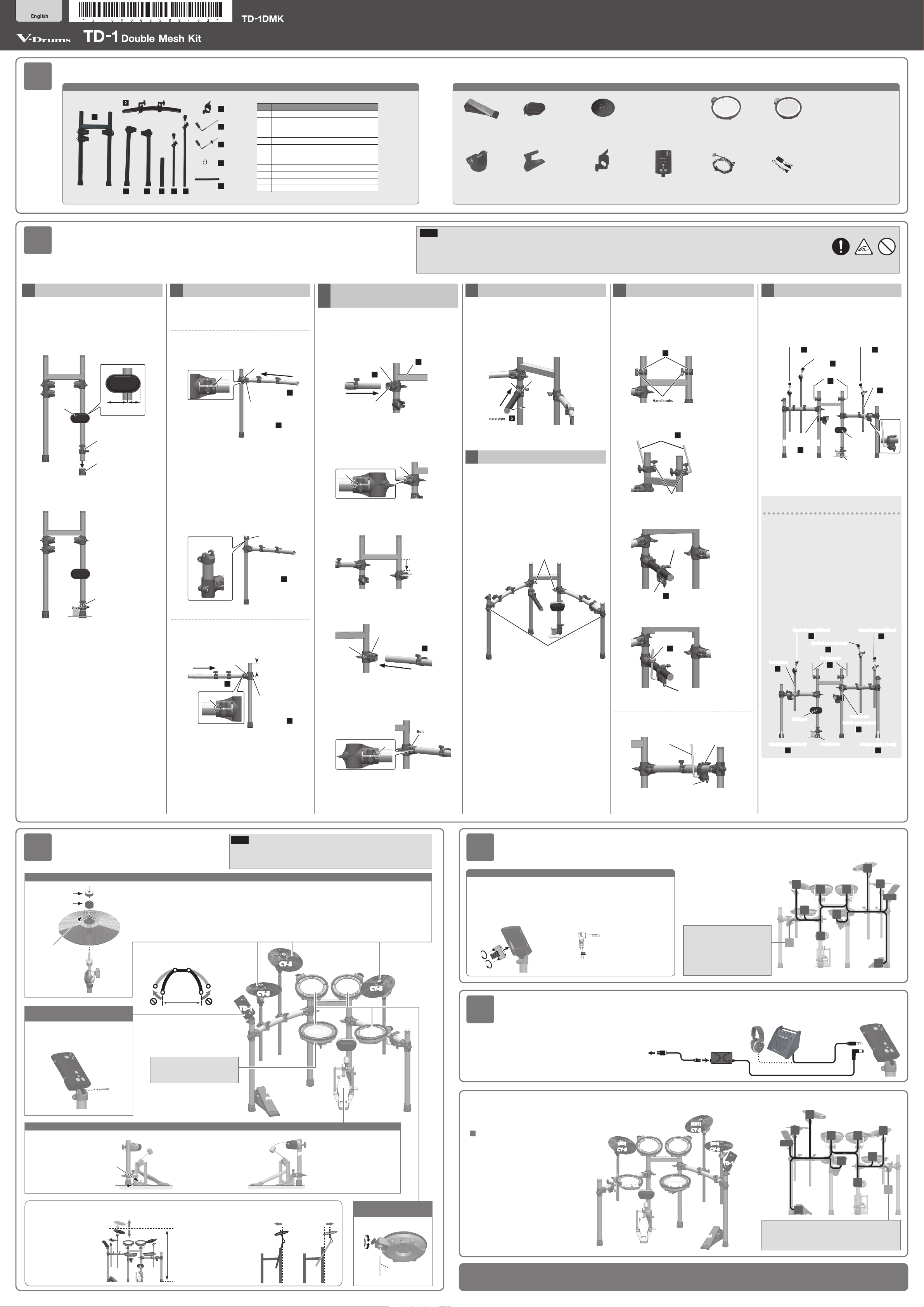
Detailed explanation of each part
9 About the memory clamp
The memory clamp aligns the pad at a xed height when it is attached.
When shipped, the memory clamp is attached at the recommended position for using the drum safely.
Rod
(pad mount)
PDX-8
Memory clamp
NOTE
If the memory clamp is moved or removed in order to adjust the position of the PDX-8 (snare), a greater length of the rod may protrude; take
care that the protruding rod does not cause injury.
9 When using a twin pedal
Position the two beaters equally apart from the center of the pad as shown in
the gure at left. If one of the beater is further away from the center than the
other, the sound from the further beater will be lower in volume, or will not
sound as desired.
If you’re using twin pedals, the sensitivity will be lower than when a single
pedal is used. Raise the sensitivity on the sound module.
For details, refer to “TD-1 Owner’s Manual.”
Correct positioning Incorrect positioning
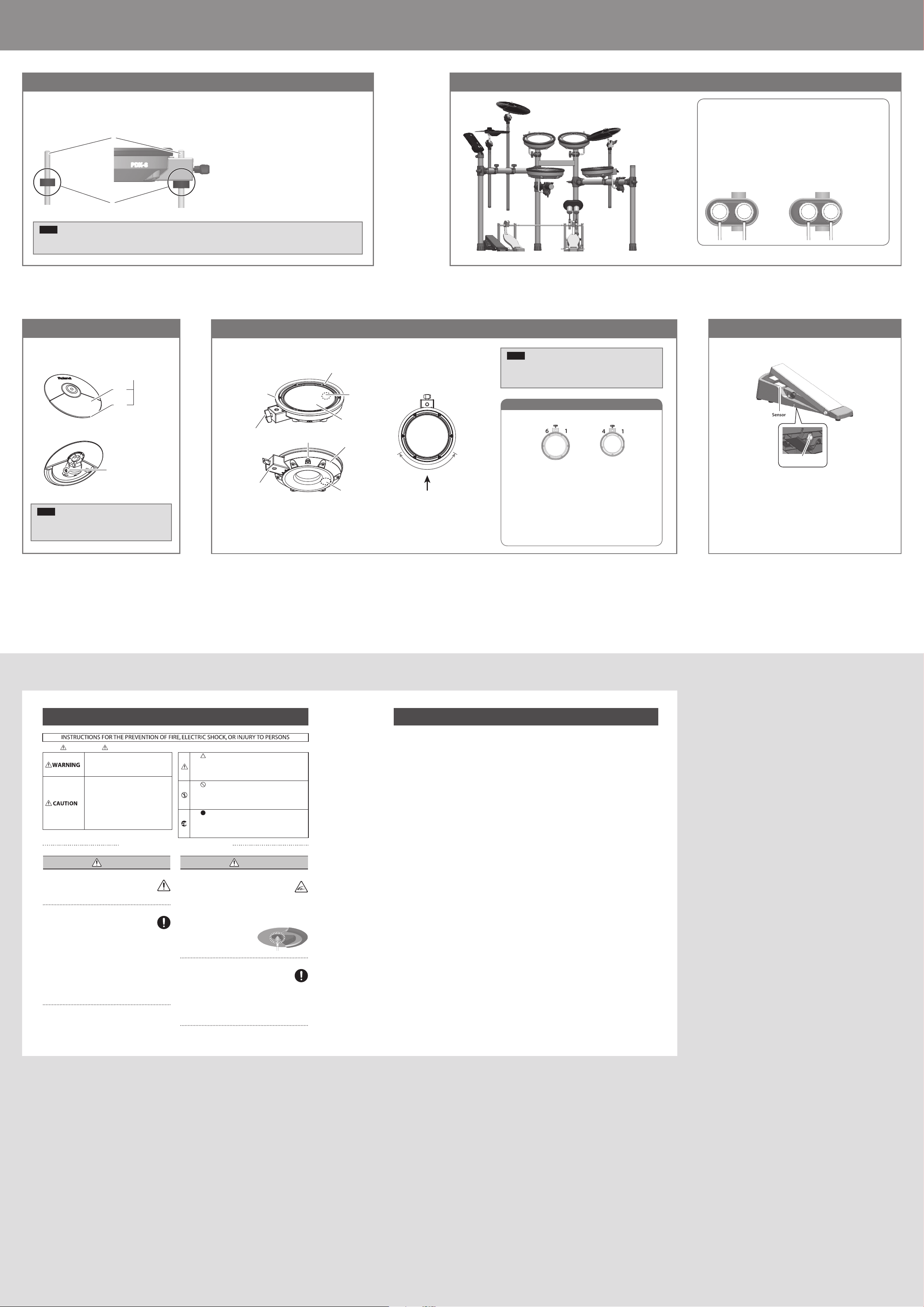
9 CY-5 (Hi-hat/Crash/Ride)
Component names
Pad face
Bow
Edge
OUTPUT jack
NOTE
Continuous playing may cause dis-coloration of the pad,
but this will not aect the pad’s function.
Component names
Hoop rubber
Knob bolt
Holder
OUTPUT jack
Tuning bolts
Head sensor
Head
Shell
Rim sensor
Player
Suitable position
for rim shots
NOTE
5 Be sure to adjust the head tension of the pad before use.
5 The PDX-6A is a new unit designed specically for the TD-1DMK.
It does not support the use of the rim-shot technique.
Adjusting the head tension
PDX-8 PDX-6A
6 1
4 3
2 5
4 1
2 3
5
1. Adjust each tuning bolt a little at a time, moving in order from
one side to the opposite side as shown in the illustration.
The appropriate amount of tension is one that will provide
approximately the same striking response as on an acoustic
drum.
2. Use the drum key to adjust the tension as needed.
9 Hi-hat control pedal9 PDX-8 (Snare) 9 PDX-6A (Tom)
Sensor
OUTPUT jack
USING THE UNIT SAFELY IMPORTANT NOTES
About WARNING and CAUTION Notices
Used for instructions intended to alert the
user to the risk of death or severe injury
should the unit be used improperly.
Used for instructions intended to alert the
user to the risk of injury or material
damage should the unit be used
improperly.
* Material damage refers to damage or
other adverse effects caused with
respect to the home and all its
furnishings, as well to domestic animals
or pets.
ALWAYS OBSERVE THE FOLLOWING
CAUTION
Evaluate safety issues before using stands
Even if you observe the cautions given in the owner’s
manual, certain types of handling may allow this product
to fall from the stand, or cause the stand to overturn.
Please be mindful of any safety issues before using this product.
Cautions when moving this unit
If you need to move the instrument, take note of the
precautions listed below. At least two persons are
required to safely lift and move the unit. It should be
handled carefully, all the while keeping it level. Make sure
to have a rm grip, to protect yourself from injury and the
instrument from damage.
• Check to make sure the knob bolts and screws securing the
stand have not become loose. Fasten them again securely
whenever you notice any loosening.
• Disconnect the power cord.
• Disconnect all cords coming from external devices.
• Disconnect the kick pedal.
• Disconnect the connection cable of the hi-hat control pedal.
About the Symbols
The symbol alerts the user to important instructions or
warnings.The specific meaning of the symbol is
determined by the design contained within the triangle. In
the case of the symbol at left, it is used for general
cautions, warnings, or alerts to danger.
The symbol alerts the user to items that must never be
carried out (are forbidden). The specific thing that must
not be done is indicated by the design contained within
the circle. In the case of the symbol at left, it means that
the unit must never be disassembled.
The symbol alerts the user to things that must be
carried out. The specific thing that must be done is
indicated by the design contained within the circle. In the
case of the symbol at left, it means that the power-cord
plug must be unplugged from the outlet.
CAUTION
Take care so as not to get ngers pinched
When handling the following moving parts, take care
so as not to get ngers, toes, etc., pinched. Whenever
a child uses the unit, an adult should be on hand to
provide supervision and guidance.
• Hi-hat control pedal
• Kick pedal
• Bottom of the cymbal pad (see gure)
Keep small items out of the reach of children
To prevent accidental ingestion of the parts listed below,
always keep them out of the reach of small children.
• Included Parts
Cymbal nuts
• Removable Parts
Screws
CR2 plug’s cap
Placement
• Depending on the material and temperature of the surface on
which you place the unit, its rubber feet may discolor or mar
the surface.
Additional Precautions
• Any data stored within the unit can be lost as the result of
equipment failure, incorrect operation, etc. To protect yourself
against the irretrievable loss of data, try to make a habit of
creating regular backups of the data you’ve stored in the unit.
• This instrument is designed to minimize the extraneous sounds
produced when it’s played. However, since sound vibrations
can be transmitted through oors and walls to a greater degree
than expected, take care not to allow these sounds to become
a nuisance others nearby.
• The rubber portion of the striking surface is treated with a
preservative to maintain its performance. With the passage of
time, this preservative may appear on the surface as a white
stain, or reveal how the pads were struck during product
testing. This does not aect the performance or functionality of
the product, and you may continue using it with condence.
• Continuous playing may cause dis-coloration of the pad, but
this will not aect the pad’s function.
• This document explains the specications of the product at the
time that the document was issued. For the latest information,
refer to the Roland website.
Intellectual Property Right
• Roland and V-Drums are either registered trademarks or
trademarks of Roland Corporation in the United States and/or
other countries.
• Company names and product names appearing in this
document are registered trademarks or trademarks of their
respective owners.
 Loading...