

Page 1
*5100007588 -01 *
Page 2
USING THE UNIT SAFELY
About WARNING and CAUTION Notices
Used for instructions intended to alert the
user to the risk of death or severe injury
should the unit be used improperly.
Used for instructions intended to alert the
user to the risk of injury or material
damage should the unit be used
improperly.
* Material damage refers to damage or
other adverse effects caused with
respect to the home and all its
furnishings, as well to domestic animals
or pets.
ALWAYS OBSERVE THE FOLLOWING
002b
• Do not open or perform any internal modifications on the
unit. (The only exception would be where this manual
provides specific instructions which should be followed
in order to put in place user-installable options.)
.................................................................................................................................................................................
003
• Do not attempt to repair the unit, or replace parts
within it (except when this manual provides specific
instructions directing you to do so). Refer all servicing
to your retailer, the nearest Roland Service Center, or
an authorized Roland distributor, as listed on the
“Information” page.
.................................................................................................................................................................................
004
• Never install the unit in any of the following locations.
• Subject to temperature extremes (e.g., direct
sunlight in an enclosed vehicle, near a heating
duct, on top of heat-generating equipment); or are
• Damp (e.g., baths, washrooms, on wet floors); or are
• Exposed to steam or smoke; or are
• Subject to salt exposure; or are
• Humid; or are
• Exposed to rain; or are
• Dusty or sandy; or are
• Subject to high levels of vibration and shakiness.
.................................................................................................................................................................................
005
This unit should be used only with a rack or stand that
•
is recommended by Roland.
.................................................................................................................................................................................
006
When using the unit with a rack or stand
•
recommended by Roland, the rack or stand must be
carefully placed so it is level and sure to remain stable.
If not using a rack or stand, you still need to make sure
that any location you choose for placing the unit
provides a level surface that will properly support the
unit, and keep it from wobbling.
.................................................................................................................................................................................
About the Symbols
The symbol alerts the user to important instructions or
warnings. The specific meaning of the symbol is
determined by the design contained within the triangle. In
the case of the symbol at left, it is used for general
cautions, warnings, or alerts to danger.
The symbol alerts the user to items that must never be
carried out (are forbidden). The specific thing that must
not be done is indicated by the design contained within
the circle. In the case of the symbol at left, it means that
the unit must never be disassembled.
The symbol alerts the user to things that must be
carried out. The specific thing that must be done is
indicated by the design contained within the circle. In the
case of the symbol at left, it means that the power-cord
plug must be unplugged from the outlet.
011
• Do not allow any objects (e.g., flammable material,
coins, pins); or liquids of any kind (water, soft drinks,
etc.) to penetrate the unit.
......................................................................................................................
013
• In households with small children, an adult should
provide supervision until the child is capable of
following all the rules essential for the safe operation
of the unit.
......................................................................................................................
014
• Protect the unit from strong impact.
(Do not drop it!)
104
Try to prevent cords and cables from becoming
•
entangled. Also, all cords and cables should be placed
so they are out of the reach of children.
......................................................................................................................
106
Never climb on top of, nor place heavy objects on the
•
unit.
......................................................................................................................
118a
•
Anything that you’ve removed, whether it be the knob
that fastens bracket, tuning bolts, washers, clip, or the
screw that fastens covering must be placed in a safe
location out of the reach of children, so there’s no
chance of them being swallowed accidentally.
......................................................................................................................
2
Page 3
IMPORTANT NOTES
Placement
354a
• Do not expose the unit to direct sunlight, place it near devices
that radiate heat, leave it inside an enclosed vehicle, or
otherwise subject it to temperature extremes. Excessive heat
can deform or discolor the unit.
355b
• When moved from one location to another where the
temperature and/or humidity is very different, water droplets
(condensation) may form inside the unit. Damage or
malfunction may result if you attempt to use the unit in this
condition. Therefore, before using the unit, you must allow it
to stand for several hours, until the condensation has
completely evaporated.
356
• Do not allow rubber, vinyl, or similar materials to remain on
the unit for long periods of time. Such objects can discolor or
otherwise harmfully affect the finish.
Maintenance
401a
• For everyday cleaning wipe the unit with a soft, dry cloth or
one that has been slightly dampened with water. To remove
stubborn dirt, use a cloth impregnated with a mild, nonabrasive detergent. Afterwards, be sure to wipe the unit
thoroughly with a soft, dry cloth.
402
• Never use benzine, thinners, alcohol or solvents of any kind, to
avoid the possibility of discoloration and/or deformation.
Additional Precautions
553
• Use a reasonable amount of care when using the unit’s
buttons, sliders, or other controls; and when using its jacks
and connectors. Rough handling can lead to malfunctions.
556
• When connecting / disconnecting all cables, grasp the
connector itself—never pull on the cable. This way you will
avoid causing shorts, or damage to the cable’s internal
elements.
558a
• To avoid disturbing your neighbors, try to keep the unit’s
volume at reasonable levels. You may prefer to use
headphones, so you do not need to be concerned about those
around you (especially when it is late at night).
558d
• This instrument is designed to minimize the extraneous
sounds produced when it’s played. However, since sound
vibrations can be transmitted through floors and walls to a
greater degree than expected, take care not to allow these
sounds to become a nuisance to neighbors, especially when
performing at night and when using headphones.
559a
• When you need to transport the unit, package it in the box
(including padding) that it came in, if possible. Otherwise, you
will need to use equivalent packaging materials.
add
• The snare stand is supported by means of a tripod. When
installing the drum set, make sure the legs of the tripod are
opened wide enough to keep the equipment from falling
over.
add
• The rubber portion is treated with a preservative to maintain
its performance. With the passage of time, this preservative
may appear on the surface as a white stain, or reveal how the
pads were struck during product testing. This does not affect
the performance or functionality of the product, and you may
continue using it with confidence.
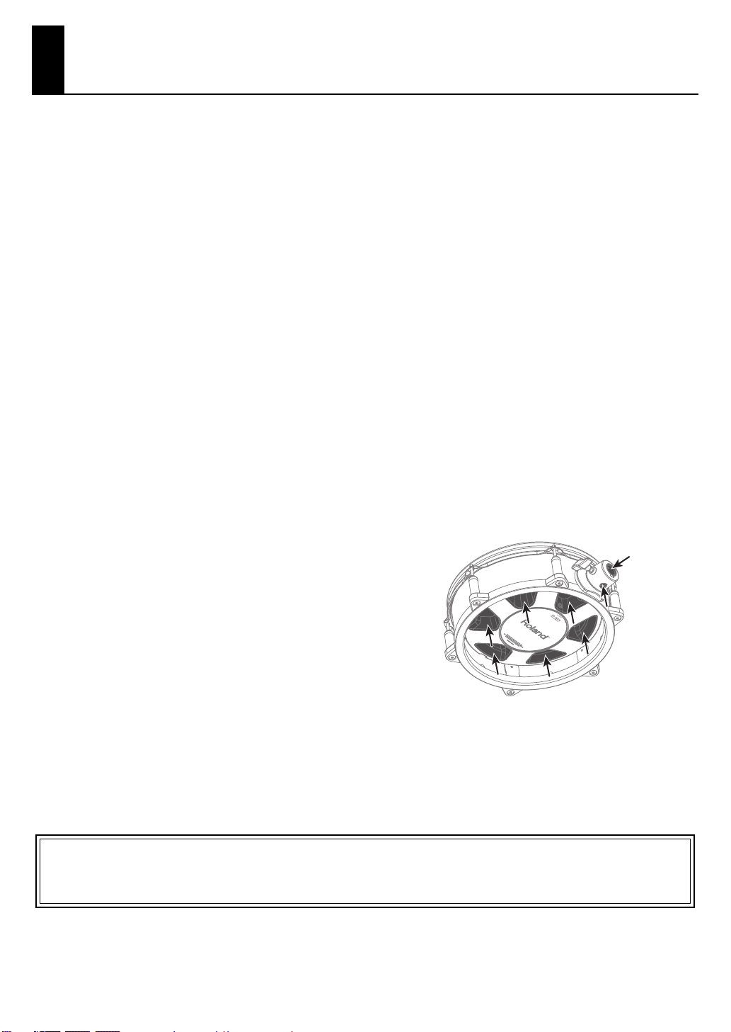
Add
• Do not insert your hands or fingers in the locations marked by
the arrows. Otherwise, you risk injury and possible damage to
this unit’s parts.
Before using this unit, carefully read the sections entitled: “USING THE UNIT SAFELY” (p. 2) and “IMPORTANT NOTES” (p. 3).
These sections provide important information concerning the proper operation of the unit. Additionally, in order to feel assured
that you have gained a good grasp of every feature provided by your new unit, Owner’s manual should be read in its entirety.
The manual should be saved and kept on hand as a convenient reference.
Copyright © 2009 ROLAND CORPORATION
All rights reserved.
No part of this publication may be reproduced in any form without the written permission of ROLAND CORPORATION.
3
Page 4
Main Features
• Snare/tom pad with mesh head allowing for excellent feel, dynamics and low level acoustics sound.
• Rim shots and playing with brushes is possible.
• The pad can mount on a V-Drums drum stand and/or commercially available tom stands (vertical rod type or horizontal pipe type p. 5)
(PD-125X/105X only).
• You can easily change the shell covering to personalize the kit’s look.
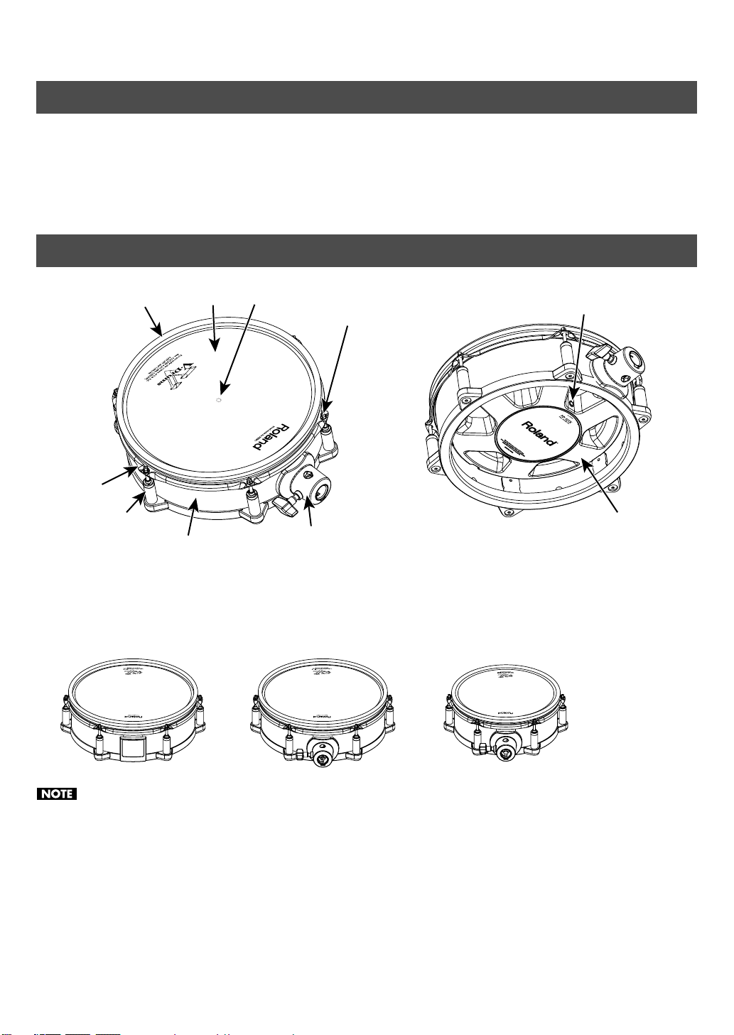
PD-125XS/125X/105X Components
Hoop rubber
Hoop (rim)
Lug
• The only difference between the PD-125X and PD-105X is their diameter.
• The PD-125XS has no bracket as it’s designed for use with a snare stand.
Head
Shell
Sensor
Tuning bolt
Bracket
(PD-125X/105X)
PD-125XPD-125XS PD-105X
Output jack
Frame
* The illustration shows the PD-125X.
• Applying excessive force to the sensor located under the head can damage it.
• Due to the nature of the materials used in the sensor, changes in temperature or humidity may affect playing dynamics or
sensor sensitivity.
4
Page 5

Mounting the Pads
Mounting the PD-125XS (Dedicated Snare Pad)
The PD-125XS (dedicated snare pad) has no mounting
bracket so can only be used with a snare stand.
Make sure that the snare stand you are using is able to
support a 12-inch shell.
Mounting the PD-125X or 105X on a Tom Stand
The PD-125X/105X can be attached to a stand that has either
a vertical rod or a horizontal pipe.
Stand with vertical rod (MDS series)
fig.03-j.epsfig
Loosen
Tighten
Rod diameter that can be attached: 9–11.5 mm (3/8–1/2 inch)
Stand with horizontal pipe
fig.03-j.epsfig
Loosen
Tighten
Usable pipe size: 22.2 mm (7/8 inch)
Mounting the PD-125X or 105X on a Snare Stand
It was already mentioned that mounting a PD-125XS requires
a snare stand that can support a 12-inch shell.
For the PD-105X, the stand must support a 10-inch shell.
Tighten the knob that fastens bracket securely to assure
the best functionality.
5
Page 6

Connecting to the Percussion Sound Module
Use the included stereo cables to connect pads to your
percussion sound module (sold separately).
Connect the L-shaped end of the cable to the pad’s OUTPUT
jack.
Using a monaural cable will NOT allow rim shots or positional
sensing.
Refer to the table below for details on trigger inputs of
sound modules supporting rim shots.
Prevent malfunction and/or damage to speakers or
other devices by always turning down the volume, and/
or power of all devices before making any connections.
Example: Percussion Sound Module TD-20X
I-shaped
plug
To OUTPUT jack
L-shaped
plug
Trigger Parameter Settings on the Sound Module
Compatibility with various sound modules
Head
Rim
Cross
Shot
Shot
TD-20X/
TDW-20/
TD-20
TD-12 o o o o o o
TD-9 o o o x x x
TD-4 o o o x x x
o o o o o o
Stick
Positional
Sensing
For details, refer to the owner’s manual of your
percussion sound module.
Rim Shot
Nuance
Brush
Sweep
Recommended parameter settings
Below please find recommended trigger parameter settings
when using the PD-125XS/125X/105X with various sound
modules.
Further trigger parameter adjustment may be needed
depending on the way in which the PD-125XS/125X/105X is
mounted or the playing environment.
For details on editing refer to the owner’s manual of your
sound module.
TD-20X/TDW-20/TD-20
Model name Trigger type
PD-125XS
PD-125X PD125
PD-105X PD105
●
Inputs that allow rim shots: 2 SNARE, 3–6 TOM 1–4, 12–15 AUX 1–4
● Inputs that allow cross-stick: 2 SNARE
● Inputs that allow positional sensing: 2 SNARE
TD-12
Model name Trigger type
PD-125XS
PD-125X PD125
PD-105X PD105
●
Inputs that allow rim shots: 2 SNARE, 3–5 TOM 1–3, 11–12 AUX 1–2
●
Inputs that allow cross-stick: 2 SNARE
●
Inputs that allow positional sensing: 2 SNARE
TD-9
Model name Trigger type
PD-125XS
PD-125X PD125
PD-105X PD105
●
Inputs that allow rim shots: SNARE, TOM 1–3, AUX
●
Inputs that allow cross-stick: SNARE
TD-4
Model name Pad type
PD-125XS
PD-125X PD-125
PD-105X PD-105
●
Inputs that allow rim shots: SNARE
●
Inputs that allow cross-stick: SNARE
PD125
PD125
PD125
PD-125
6
Page 7

Adjusting the Head Tension
Replacing the Head or Hoop
Before playing you must adjust the pad tension first.
You can tune/adjust the head tension as you would with an
acoustic drum, to get the same dynamic “feel.”
The pad will function at it’s best if you are sure to:
• Adjust the head evenly so that it does not sag.
fig.19-e.eps.80
• Adjust the tuning bolts so that they are not loose.
46
5
Adjust each tuning bolt little by little, across the
1.
head as indicated in the illustration. The assures
even tensioning.
• Fully tightening a tuning bolt at only a single location
produces uneven tensioning, and correct playing
dynamics may not be achieved. Even tuning/
tensioning is very important.
• Head tension will not affect the actual tuning of the
sound you are playing. For that you need to adjust
sound parameters in the sound module you are
using.
Also, head tension may change depending on usage.
Adjust as needed.
3
Rubber
The performance of the head and/or hoop rubber will
diminish with use over time. If the head is torn or becomes
too fatigued, or impossible to tension correctly, then it
should be replaced. If the hoop rubber is worn out, it too can
be replaced.
For replacement heads or to have the hoop rubber replaced,
please contact your dealer or a Roland service center.
Replacing the Head
Applying excessive force to the sensor located under
12
1.
2.
3.
4.
5.
the head can damage it and/or interfere with accurate
triggering.
Remove all tuning bolts.
Go around and loosen each bolt a little at a time by turning it
counter-clockwise.
Remove the hoop and old head.
Place the new head and hoop on the shell.
Install all six tuning bolts.
Adjust the tension of the head. Refer to “Adjusting
the head tension” above.
7
Page 8

Replacing the Shell Covering
• Applying excessive force to the sensor located under
the head can damage it and/or interfere with
accurate triggering.
• Be careful not to hurt your fingers on the corners or
points of the metal parts.
1.
Loosen all tuning bolts, and remove the hoop and
head.
Hoop
Head
Do not touch the sensor located
at the top of the frame.
Pull the fastening clip upward and out, and remove
4.
the covering.
Fastening Clip
Covering
5.
Attach the new covering.
Insert the lower part of the covering into the rubber groove
so that the upper edge of the covering is in the position
shown in the illustration.
The upper edge
of the covering
Both edges of the covering will fit into the gap between the
shell and plate.
2.
Remove the frame.
Frame
3.
Use a Philips screwdriver to loosen the screw that
fastens the covering by approximately two full turns.
Screw
Plate
Covering
Shell
6.
While pulling on both ends of the covering so as to
Screw
eliminate any slack, finger-tighten the screw that
holds the covering in place.
7.
Using a
Philips s
crewdriver, securely fasten the
screw that holds the covering in place.
8.
Attach the fastening clip in the location shown in the
illustration, as if to pinch the two ends of the covering.
Fastening clip
8
Page 9

Install the frame in the shell.
9.
The frame’s output jack will be pointing in the same direction
as the bracket.
Protrusion
Groove
Attach the hoop and head, and tighten the tuning
10.
Output jack
Frame
Shell
Bracket
Match up the protrusion
on the frame with the
groove on the shell.
bolts.
11.
Adjust the tension of the head.
Refer to “Adjusting the Head Tension” (p. 7).
Covering size
PD-125XS/PD-125X
• 77 (Width) x 927 (Length) mm
77 mm
• Maximum Thickness: 1 mm
PD-105X
• 77 (Width) x 767 (Length) mm
767 mm
77 mm
• Maximum Thickness: 1 mm
927 mm
9
Page 10

Playing Methods
Head shots
fig.Head.e
Only playing the head
and with certain snare
sounds, the playing
position will change the
sound’s nuance.
Head
Change the Nuance of the Rim Shot (Only with the TD-20X/TDW-20/TD-20/ TD-12)
With certain snare and tom sounds, slight changes in the way
you play rim shots changes the nuance.
See the TD-20X/TDW-20/TD-20/TD-12 owner’s manual
for more info about which sounds allow this.
Rim shots
fig.Rim.e
Strike the head and the
rim of the pad
simultaneously.
Cross stick
Only strike the rim of the
pad.
Depending on the
instrument assigned to
the rim you can play rim
shots and/or cross stick
sounds.
To play the cross stick, be sure that you only strike the
rim of the pad. Placing your hand on the head of the
pad might prevent the cross stick sound from being
played properly.
Head
Rim
Do not place your hand
on the head
Rim
Normal rim shots (open rim shots)
Strike the head and rim
simultaneously.
Head
Rim
Shallow rim shots
Simultaneously strike the
head near the rim and
the rim itself.
Head
Rim
• See the TD-20X/TDW-20/TD-20/TD-12 owner’s
manual for more info about which sounds allow this.
• For more information on the trigger inputs of the
various sound modules that support the use of rim
shots, refer to p. 6.
10
Page 11

Specifications
PD-125XS/PD-125X/PD-105X: V-Pad
PD-125XS PD-125X PD-105X
Pad size
Trigger 2 (Head, Rim)
Bracket – – – o o
Dimensions
Weights
Accessories
Options – – – Pad Mount (MDH series), Stand (MDS series)
In the interest of product improvement, the specifications and/or appearance of this unit are subject to change without prior
notice.
12 inch 12 inch 10 inch
358 (W) x 322 (D) x 117 (H) mm
14-1/8 (W) x 12-11/16 (D) x 4-5/8 (H) inches
3.0 kg
6 lbs 10 oz
358 (W) x 368 (D) x 117 (H) mm
14-1/8 (W) x 14-1/2 (D) x 4-5/8 (H) inches
3.4 kg
7 lbs 8 oz
Owner’s manual, Connection cable (*1), Drum key (*1)
*1 Supplied only if the PD-125XS/125X/105X has been purchased as an independent unit.
307 (W) x 317 (D) x 117 (H) mm
12-1/8 (W) x 12-1/2 (D) x 4-5/8 (H) inches
3.0 kg
6 lbs 10 oz
11
Page 12

For EU Countries
For China
For C.A. US (Proposition 65
WARNING
This product contains chemicals known to cause cancer, birth defects and other reproductive harm, including lead.
)
Page 13

Information
When you need repair service, call your nearest Roland Service Center or authorized Roland
distributor in your country as shown below.
AFRICA
EGYPT
Al Fanny Trading Office
9, EBN Hagar Al Askalany Street,
ARD E1 Golf, Heliopolis,
Cairo 11341, EGYPT
TEL: (022)-417-1828
REUNION
Maison FO - YAM Marcel
25 Rue Jules Hermann,
Chaudron - BP79 97 491
Ste Clotilde Cedex,
REUNION ISLAND
TEL: (0262) 218-429
SOUTH AFRICA
T.O.M.S. Sound & Music (Pty)Ltd.
2 ASTRON ROAD DENVER
JOHANNESBURG ZA 2195,
SOUTH AFRICA
TEL: (011)417 3400
Paul Bothner(PTY)Ltd.
Royal Cape Park, Unit 24
Londonderry Road, Ottery 7800
Cape Town, SOUTH AFRICA
TEL: (021) 799 4900
ASIA
CHINA
Roland Shanghai Electronics
Co.,Ltd.
5F. No.1500 Pingliang Road
Shanghai 200090, CHINA
TEL: (021) 5580-0800
Roland Shanghai Electronics
Co.,Ltd.
(BEIJING OFFICE)
10F. No.18 3 Section Anhuaxili
Chaoyang District Beijing 100011
CHINA
TEL: (010) 6426-5050
HONG KONG
Tom Lee Music Co., Ltd. Service
Division
22-32 Pun Shan Street, Tsuen
Wan, New Territories,
HONG KONG
TEL: 2415 0911
Parsons Music Ltd.
8th Floor, Railway Plaza, 39
Chatham Road South, T.S.T,
Kowloon, HONG KONG
TEL: 2333 1863
INDIA
Rivera Digitec (India) Pvt. Ltd.
411, Nirman Kendra Mahalaxmi
Flats Compound Off. Dr. Edwin
Moses Road, Mumbai-400011,
INDIA
TEL: (022) 2493 9051
INDONESIA
PT Citra IntiRama
Jl. Cideng Timur No. 15J-15O
Jakarta Pusat
INDONESIA
TEL: (021) 6324170
KOREA
Cosmos Corporation
1461-9, Seocho-Dong,
Seocho Ku, Seoul, KOREA
TEL: (02) 3486-8855
MALAYSIA
Roland Asia Pacific Sdn. Bhd.
45-1, Block C2, Jalan PJU 1/39,
Dataran Prima, 47301 Petaling
Jaya, Selangor, MALAYSIA
TEL: (03) 7805-3263
VIET NAM
VIET THUONG CORPORATION
386 CACH MANG THANG TAM ST.
DIST.3,
HO CHI MINH CITY
VIET NAM
TEL: 9316540
PHILIPPINES
G.A. Yupangco & Co. Inc.
339 Gil J. Puyat Avenue
Makati, Metro Manila 1200,
PHILIPPINES
TEL: (02) 899 9801
SINGAPORE
SWEE LEE MUSIC COMPANY
PTE. LTD.
150 Sims Drive,
SINGAPORE 387381
TEL: 6846-3676
TAIWAN
ROLAND TAIWAN ENTERPRISE
CO., LTD.
Room 5, 9fl. No. 112 Chung Shan
N.Road Sec.2, Taipei, TAIWAN,
R.O.C.
TEL: (02) 2561 3339
THAILAND
Theera Music Co. , Ltd.
100-108 Soi Verng Nakornkasem,
New Road,Sumpantawongse,
Bangkok 10100 THAILAND
TEL: (02) 224-8821
OCEANIA
AUSTRALIA/
NEW ZEALAND
Roland Corporation
Australia Pty.,Ltd.
38 Campbell Avenue
Dee Why West. NSW 2099
AUSTRALIA
For Australia
Tel: (02) 9982 8266
For New Zealand
Tel: (09) 3098 715
CENTRAL/LATIN
AMERICA
ARGENTINA
Instrumentos Musicales S.A.
Av.Santa Fe 2055
(1123) Buenos Aires
ARGENTINA
TEL: (011) 4508-2700
BARBADOS
A&B Music Supplies LTD
12 Webster Industrial Park
Wildey, St.Michael, Barbados
TEL: (246)430-1100
BRAZIL
Roland Brasil Ltda.
Rua San Jose, 211
Parque Industrial San Jose
Cotia - Sao Paulo - SP, BRAZIL
TEL: (011) 4615 5666
CHILE
Comercial Fancy II S.A.
Rut.: 96.919.420-1
Nataniel Cox #739, 4th Floor
Santiago - Centro, CHILE
TEL: (02) 688-9540
COLOMBIA
Centro Musical Ltda.
Cra 43 B No 25 A 41 Bododega 9
Medellin, Colombia
TEL: (574)3812529
COSTA RICA
JUAN Bansbach Instrumentos
Musicales
Ave.1. Calle 11, Apartado 10237,
San Jose, COSTA RICA
TEL: 258-0211
CURACAO
Zeelandia Music Center Inc.
Orionweg 30
Curacao, Netherland Antilles
TEL:(305)5926866
DOMINICAN REPUBLIC
Instrumentos Fernando Giraldez
Calle Proyecto Central No.3
Ens.La Esperilla
Santo Domingo,
Dominican Republic
TEL:(809) 683 0305
ECUADOR
Mas Musika
Rumichaca 822 y Zaruma
Guayaquil - Ecuador
TEL:(593-4)2302364
EL SALVADOR
OMNI MUSIC
75 Avenida Norte y Final Alameda
Juan Pablo II,
Edificio No.4010 San Salvador,
EL SALVADOR
TEL: 262-0788
GUATEMALA
Casa Instrumental
Calzada Roosevelt 34-01,zona 11
Ciudad de Guatemala
Guatemala
TEL:(502) 599-2888
HONDURAS
Almacen Pajaro Azul S.A. de C.V.
BO.Paz Barahona
3 Ave.11 Calle S.O
San Pedro Sula, Honduras
TEL: (504) 553-2029
MARTINIQUE
Musique & Son
Z.I.Les Mangle
97232 Le Lamantin
Martinique F.W.I.
TEL: 596 596 426860
Gigamusic SARL
10 Rte De La Folie
97200 Fort De France
Martinique F.W.I.
TEL: 596 596 715222
MEXICO
Casa Veerkamp, s.a. de c.v.
Av. Toluca No. 323, Col. Olivar de
los Padres 01780 Mexico D.F.
MEXICO
TEL: (55) 5668-6699
NICARAGUA
Bansbach Instrumentos
Musicales Nicaragua
Altamira D'Este Calle Principal
de la Farmacia 5ta.Avenida
1 Cuadra al Lago.#503
Managua, Nicaragua
TEL: (505)277-2557
PANAMA
SUPRO MUNDIAL, S.A.
Boulevard Andrews, Albrook,
Panama City, REP. DE PANAMA
TEL: 315-0101
PARAGUAY
Distribuidora De Instrumentos
Musicales
J.E. Olear y ESQ. Manduvira
Asuncion PARAGUAY
TEL: (595) 21 492147
PERU
Audionet
Distribuciones Musicales SAC
Juan Fanning 530
Miraflores
Lima - Peru
TEL: (511) 4461388
TRINIDAD
AMR Ltd
Ground Floor
Maritime Plaza
Barataria Trinidad W.I.
TEL: (868) 638 6385
URUGUAY
Todo Musica S.A.
Francisco Acuna de Figueroa
1771
C.P.: 11.800
Montevideo, URUGUAY
TEL: (02) 924-2335
VENEZUELA
Instrumentos Musicales
Allegro,C.A.
Av.las industrias edf.Guitar import
#7 zona Industrial de Turumo
Caracas, Venezuela
TEL: (212) 244-1122
EUROPE
AUSTRIA
Roland Elektronische
Musikinstrumente HmbH.
Austrian Office
Eduard-Bodem-Gasse 8,
A-6020 Innsbruck, AUSTRIA
TEL: (0512) 26 44 260
BELGIUM/FRANCE/
HOLLAND/
LUXEMBOURG
Roland Central Europe N.V.
Houtstraat 3, B-2260, Oevel
(Westerlo) BELGIUM
TEL: (014) 575811
CROATIA
ART-CENTAR
Degenova 3.
HR - 10000 Zagreb
TEL: (1) 466 8493
CZECH REP.
CZECH REPUBLIC DISTRIBUTOR
s.r.o
Voctárova 247/16
CZ - 180 00 PRAHA 8,
CZECH REP.
TEL: (2) 830 20270
DENMARK
Roland Scandinavia A/S
Nordhavnsvej 7, Postbox 880,
DK-2100 Copenhagen
DENMARK
TEL: 3916 6200
FINLAND
Roland Scandinavia As, Filial
Finland
Elannontie 5
FIN-01510 Vantaa, FINLAND
TEL: (0)9 68 24 020
GERMANY
Roland Elektronische
Musikinstrumente HmbH.
Oststrasse 96, 22844 Norderstedt,
GERMANY
TEL: (040) 52 60090
GREECE/CYPRUS
STOLLAS S.A.
Music Sound Light
155, New National Road
Patras 26442, GREECE
TEL: 2610 435400
HUNGARY
Roland East Europe Ltd.
Warehouse Area ‘DEPO’ Pf.83
H-2046 Torokbalint, HUNGARY
TEL: (23) 511011
IRELAND
Roland Ireland
G2 Calmount Park, Calmount
Avenue, Dublin 12
Republic of IRELAND
TEL: (01) 4294444
ITALY
Roland Italy S. p. A.
Viale delle Industrie 8,
20020 Arese, Milano, ITALY
TEL: (02) 937-78300
NORWAY
Roland Scandinavia Avd.
Kontor Norge
Lilleakerveien 2 Postboks 95
Lilleaker N-0216 Oslo
NORWAY
TEL: 2273 0074
POLAND
ROLAND POLSKA SP. Z O.O.
ul. Kty Grodziskie 16B
03-289 Warszawa, POLAND
TEL: (022) 678 9512
PORTUGAL
Roland Iberia, S.L.
Portugal Office
Cais das Pedras, 8/9-1 Dto
4050-465, Porto, PORTUGAL
TEL: 22 608 00 60
ROMANIA
FBS LINES
Piata Libertatii 1,
535500 Gheorgheni, ROMANIA
TEL: (266) 364 609
RUSSIA
MuTek
Dorozhnaya ul.3,korp.6
117 545 Moscow, RUSSIA
TEL: (095) 981-4967
SLOVAKIA
DAN Acoustic s.r.o.
Povazská 18.
SK - 940 01 Nové Zámky
TEL: (035) 6424 330
SPAIN
Roland Iberia, S.L.
Paseo García Faria, 33-35
08005 Barcelona SPAIN
TEL: 93 493 91 00
SWEDEN
Roland Scandinavia A/S
SWEDISH SALES OFFICE
Danvik Center 28, 2 tr.
S-131 30 Nacka SWEDEN
TEL: (0)8 702 00 20
SWITZERLAND
Roland (Switzerland) AG
Landstrasse 5, Postfach,
CH-4452 Itingen, SWITZERLAND
TEL:(061)975-9987
UKRAINE
EURHYTHMICS Ltd.
P.O.Box: 37-a.
Nedecey Str. 30
UA - 89600 Mukachevo, UKRAINE
TEL: (03131) 414-40
UNITED KINGDOM
Roland (U.K.) Ltd.
Atlantic Close, Swansea
Enterprise Park, SWANSEA
SA7 9FJ,
UNITED KINGDOM
TEL: (01792) 702701
MIDDLE EAST
BAHRAIN
Moon Stores
No.1231&1249 Rumaytha
Building Road 3931, Manama 339
BAHRAIN
TEL: 17 813 942
IRAN
MOCO INC.
No.41 Nike St., Dr.Shariyati Ave.,
Roberoye Cerahe Mirdamad
Tehran, IRAN
TEL: (021)-2285-4169
ISRAEL
Halilit P. Greenspoon & Sons
Ltd.
8 Retzif Ha'alia Hashnia St.
Tel-Aviv-Yafo ISRAEL
TEL: (03) 6823666
JORDAN
MUSIC HOUSE CO. LTD. FREDDY
FOR MUSIC
P. O. Box 922846
Amman 11192 JORDAN
TEL: (06) 5692696
KUWAIT
EASA HUSAIN AL-YOUSIFI &
SONS CO.
Al-Yousifi Service Center
P.O.Box 126 (Safat) 13002
KUWAIT
TEL: 00 965 802929
LEBANON
Chahine S.A.L.
George Zeidan St., Chahine Bldg.,
Achrafieh, P.O.Box: 16-5857
Beirut, LEBANON
TEL: (01) 20-1441
OMAN
TALENTZ CENTRE L.L.C.
Malatan House No.1
Al Noor Street, Ruwi
SULTANATE OF OMAN
TEL: 2478 3443
QATAR
Al Emadi Co. (Badie Studio &
Stores)
P.O. Box 62, Doha, QATAR
TEL: 4423-554
SAUDI ARABIA
aDawliah Universal Electronics
APL
Behind Pizza Inn
Prince Turkey Street
aDawliah Building,
PO BOX 2154,
Alkhobar 31952
SAUDI ARABIA
TEL: (03) 8643601
SYRIA
Technical Light & Sound Center
PO BOX 13520 BLDG No.17
ABDUL WAHAB KANAWATI.ST
RAWDA DAMASCUS, SYRIA
TEL: (011) 223-5384
TURKEY
ZUHAL DIS TICARET A.S.
Galip Dede Cad. No.37
Beyoglu - Istanbul / TURKEY
TEL: (0212) 249 85 10
U.A.E.
Zak Electronics & Musical
Instruments Co. L.L.C.
Zabeel Road, Al Sherooq Bldg.,
No. 14, Ground Floor, Dubai,
U.A.E.
TEL: (04) 3360715
NORTH AMERICA
CANADA
Roland Canada Ltd.
(Head Office)
5480 Parkwood Way Richmond B.
C., V6V 2M4 CANADA
TEL: (604) 270 6626
Roland Canada Ltd.
(Toronto Office)
170 Admiral Boulevard
Mississauga On L5T 2N6 CANADA
TEL: (905) 362 9707
U. S. A.
Roland Corporation U.S.
5100 S. Eastern Avenue
Los Angeles, CA 90040-2938,
U. S. A.
TEL: (323) 890 3700
As of Jan. 1, 2009 (ROLAND)
 Loading...