

Page 1

Reference Manual
Copyright © 2015 ROLAND CORPORATION
01
Page 2

Contents
An Overview of the E-A7 . . . . . . . . . . . . . . . . . . . . . . . . . . . . . . . . . . 3
Basic Structure . . . . . . . . . . . . . . . . . . . . . . . . . . . . . . . . . . . . . . . . . . . . 3
Units of Sound . . . . . . . . . . . . . . . . . . . . . . . . . . . . . . . . . . . . . . . . . . . . 3
User Program (UPG) . . . . . . . . . . . . . . . . . . . . . . . . . . . . . . . . . . . . . . . . 4
Eects . . . . . . . . . . . . . . . . . . . . . . . . . . . . . . . . . . . . . . . . . . . . . . . . . . 5
About the Styles . . . . . . . . . . . . . . . . . . . . . . . . . . . . . . . . . . . . . . . . . . 5
About the Memory . . . . . . . . . . . . . . . . . . . . . . . . . . . . . . . . . . . . . . . . 6
Memory Structure . . . . . . . . . . . . . . . . . . . . . . . . . . . . . . . . . . . . 6
Menu Options . . . . . . . . . . . . . . . . . . . . . . . . . . . . . . . . . . . . . . . . . . . . 7
Global Parameters . . . . . . . . . . . . . . . . . . . . . . . . . . . . . . . . . . . . . . . . 8
User Program Edit Parameters . . . . . . . . . . . . . . . . . . . . . . . . . . . . 11
Keyboard Part Mixer Parameters . . . . . . . . . . . . . . . . . . . . . . . . . . . . . . 11
Keyboard Part MFX Parameters . . . . . . . . . . . . . . . . . . . . . . . . . . . . . . . 13
Style Part Mixer Parameters . . . . . . . . . . . . . . . . . . . . . . . . . . . . . . . . . . 14
Arranger Setting Parameters . . . . . . . . . . . . . . . . . . . . . . . . . . . . . . . . . 14
Melody Intelligent Parameters . . . . . . . . . . . . . . . . . . . . . . . . . . . . . . . . 16
Split . . . . . . . . . . . . . . . . . . . . . . . . . . . . . . . . . . . . . . . . . . . . . . . . . . . . 17
Scale Tune Switch . . . . . . . . . . . . . . . . . . . . . . . . . . . . . . . . . . . . . . . . . 17
Scale Tune . . . . . . . . . . . . . . . . . . . . . . . . . . . . . . . . . . . . . . . . . . . . . . . 17
Using Scale Tunings . . . . . . . . . . . . . . . . . . . . . . . . . . . . . . . . . . 18
Pad Setting Parameters . . . . . . . . . . . . . . . . . . . . . . . . . . . . . . . . . . . . . 18
Playing the Pads . . . . . . . . . . . . . . . . . . . . . . . . . . . . . . . . . . . . . 18
Pad Settings . . . . . . . . . . . . . . . . . . . . . . . . . . . . . . . . . . . . . . . . 19
Creating a Phrase to Play from a Pad (Phrase Recording) . . . . . . . 20
Assignable Setting Parameters . . . . . . . . . . . . . . . . . . . . . . . . . . . . . . . 20
Style Composer . . . . . . . . . . . . . . . . . . . . . . . . . . . . . . . . . . . . . . . . . . . 39
What Are Style? . . . . . . . . . . . . . . . . . . . . . . . . . . . . . . . . . . . . . . . . . . . 39
Using the Style Composer . . . . . . . . . . . . . . . . . . . . . . . . . . . . . . . . . . . 39
Initializing a Style (Initialize) . . . . . . . . . . . . . . . . . . . . . . . . . . . . . . . . . . 39
Getting Ready to Record . . . . . . . . . . . . . . . . . . . . . . . . . . . . . . . . . . . . 40
Recording a Track . . . . . . . . . . . . . . . . . . . . . . . . . . . . . . . . . . . . . . . . . . 41
Returning a Recorded Track to the State Prior to Recording (UNDO) . . . 42
Saving Your Style . . . . . . . . . . . . . . . . . . . . . . . . . . . . . . . . . . . . . . . . . . 42
Muting Tracks While Recording Others . . . . . . . . . . . . . . . . . . . . . . . . . 42
Solo . . . . . . . . . . . . . . . . . . . . . . . . . . . . . . . . . . . . . . . . . . . . . . . . . . . . 42
Playback in Arranger Mode . . . . . . . . . . . . . . . . . . . . . . . . . . . . . 42
Style Track Edit Functions . . . . . . . . . . . . . . . . . . . . . . . . . . . . . . . . . . . 42
Editing Individual Style Events (Micro Edit) . . . . . . . . . . . . . . . . . . . . . . 47
About “Alteration Mode” Messages . . . . . . . . . . . . . . . . . . . . . . . 48
Makeup Tools (Styles and SMF) . . . . . . . . . . . . . . . . . . . . . . . . . . . 50
Using the Makeup Tools . . . . . . . . . . . . . . . . . . . . . . . . . . . . . . . . . . . . . 50
Common . . . . . . . . . . . . . . . . . . . . . . . . . . . . . . . . . . . . . . . . . . . . . . . . 50
Instrument . . . . . . . . . . . . . . . . . . . . . . . . . . . . . . . . . . . . . . . . . . . . . . . 51
Freeze Data . . . . . . . . . . . . . . . . . . . . . . . . . . . . . . . . . . . . . . . . . . . . . . 54
Saving Your New Style or Song (SMF) Version . . . . . . . . . . . . . . . . . . . . 54
Using the Mark and Jump Function (SMF Songs Only) . . . . 55
Creating/Deleting Markers . . . . . . . . . . . . . . . . . . . . . . . . . . . . . . . . . . . 55
Saving a Song That Contains Markers . . . . . . . . . . . . . . . . . . . . . . . . . . 55
Using Markers to Perform . . . . . . . . . . . . . . . . . . . . . . . . . . . . . . . . . . . 55
Lyrics . . . . . . . . . . . . . . . . . . . . . . . . . . . . . . . . . . . . . . . . . . . . . . . . . . . . . 56
One Touch Setting . . . . . . . . . . . . . . . . . . . . . . . . . . . . . . . . . . . . . . . . 23
Selecting a One Touch Memory . . . . . . . . . . . . . . . . . . . . . . . . . . . . . . . 23
Canceling the One Touch Memories . . . . . . . . . . . . . . . . . . . . . . . . . . . 23
Locking One Touch Memories Settings (One Touch Lock) . . . . . . . . . . . 23
Creating Your Own One Touch Memories (One Touch Settings) . . . . . . . 23
Editing and Saving the One Touch Settings of a Style . . . . . . . . . 23
Copying a User Program or One Touch Memory to Another One
Touch Memory
. . . . . . . . . . . . . . . . . . . . . . . . . . . . . . . . . . . . . . 24
Sampling Menu . . . . . . . . . . . . . . . . . . . . . . . . . . . . . . . . . . . . . . . . . . . 25
Overall Workow . . . . . . . . . . . . . . . . . . . . . . . . . . . . . . . . . . . . . . . . . . 25
Obtaining Waveforms . . . . . . . . . . . . . . . . . . . . . . . . . . . . . . . . . . . . . . 25
Connecting an External Device . . . . . . . . . . . . . . . . . . . . . . . . . . . . . . . 25
Sampling . . . . . . . . . . . . . . . . . . . . . . . . . . . . . . . . . . . . . . . . . . . . . . . . 26
Importing Samples . . . . . . . . . . . . . . . . . . . . . . . . . . . . . . . . . . . . . . . . 26
Sample Editing . . . . . . . . . . . . . . . . . . . . . . . . . . . . . . . . . . . . . . . . . . . 26
Deleting a Sample . . . . . . . . . . . . . . . . . . . . . . . . . . . . . . . . . . . . . . . . . 27
Creating a Multisample (Create Multisample) . . . . . . . . . . . . . . . . . . . . 28
Multisample Editing . . . . . . . . . . . . . . . . . . . . . . . . . . . . . . . . . . . . . . . . 28
Deleting a Multisample . . . . . . . . . . . . . . . . . . . . . . . . . . . . . . . . . . . . . 29
User Tone . . . . . . . . . . . . . . . . . . . . . . . . . . . . . . . . . . . . . . . . . . . . . . . . 29
Creating a User Tone . . . . . . . . . . . . . . . . . . . . . . . . . . . . . . . . . . . . . . . 29
User Tone Parameters . . . . . . . . . . . . . . . . . . . . . . . . . . . . . . . . . 30
Deleting a User Tone . . . . . . . . . . . . . . . . . . . . . . . . . . . . . . . . . . . . . . . 32
Exporting User Tones to a USB Flash Drive (UST Export) . . . . . . . . . . . . . 33
Loading Exported User Tones . . . . . . . . . . . . . . . . . . . . . . . . . . . . . . . . 33
User Drum Kit . . . . . . . . . . . . . . . . . . . . . . . . . . . . . . . . . . . . . . . . . . . . 33
Creating a User Drum Kit . . . . . . . . . . . . . . . . . . . . . . . . . . . . . . . . . . . . 33
User Drum Kit Parameters . . . . . . . . . . . . . . . . . . . . . . . . . . . . . . 35
Deleting a User Drum Kit . . . . . . . . . . . . . . . . . . . . . . . . . . . . . . . . . . . . 37
Exporting User Drum Kits to a USB Flash Drive (UDK Export) . . . . . . . . . 37
Loading Exported User Drum Kits (UDK Import) . . . . . . . . . . . . . . . . . . 37
Increasing the Amount of Free Sample Memory . . . . . . . . . . . . . . . . . . 38
Truncating a Sample . . . . . . . . . . . . . . . . . . . . . . . . . . . . . . . . . . 38
Sample Clean Up . . . . . . . . . . . . . . . . . . . . . . . . . . . . . . . . . . . . . 38
Optimizing Sample Memory . . . . . . . . . . . . . . . . . . . . . . . . . . . . 38
Mastering Tools . . . . . . . . . . . . . . . . . . . . . . . . . . . . . . . . . . . . . . . . . . . 57
MIDI Parameters . . . . . . . . . . . . . . . . . . . . . . . . . . . . . . . . . . . . . . . . . . 59
Local . . . . . . . . . . . . . . . . . . . . . . . . . . . . . . . . . . . . . . . . . . . . . . . . . . . 59
Loading a MIDI Set . . . . . . . . . . . . . . . . . . . . . . . . . . . . . . . . . . . . . . . . . 59
Edit Style Parts . . . . . . . . . . . . . . . . . . . . . . . . . . . . . . . . . . . . . . . . . . . . 59
Edit Tone Parts . . . . . . . . . . . . . . . . . . . . . . . . . . . . . . . . . . . . . . . . . . . . 61
Edit Song Parts. . . . . . . . . . . . . . . . . . . . . . . . . . . . . . . . . . . . . . . . . . . . 61
Edit System . . . . . . . . . . . . . . . . . . . . . . . . . . . . . . . . . . . . . . . . . . . . . . 61
Using File Utility . . . . . . . . . . . . . . . . . . . . . . . . . . . . . . . . . . . . . . . . . . 66
Displaying the File List . . . . . . . . . . . . . . . . . . . . . . . . . . . . . . . . . . . . . . 66
Renaming a File or Folder (Rename) . . . . . . . . . . . . . . . . . . . . . . . . . . . 66
Copying a File or Folder (Copy) . . . . . . . . . . . . . . . . . . . . . . . . . . . . . . . 66
Deleting a File or Folder (Delete) . . . . . . . . . . . . . . . . . . . . . . . . . . . . . . 66
Creating a New Folder (Create Folder) . . . . . . . . . . . . . . . . . . . . . . . . . . 66
Backing Up or Initializing Data (Utility) . . . . . . . . . . . . . . . . . . . 67
Saving Data to USB Flash Drive (Backup) . . . . . . . . . . . . . . . . . . . . . . . . 67
Restoring Saved Data from USB Memory Back into the E-A7 (Restore) . 67
Initializing USB Flash Drive (USB Memory Format) . . . . . . . . . . . . . . . . . 67
Returning to the Factory Settings (Factory Reset) . . . . . . . . . . . . . . . . . 67
Viewing the Version (Version Info) . . . . . . . . . . . . . . . . . . . . . . . . . . . . . 67
E-A7 Troubleshooting . . . . . . . . . . . . . . . . . . . . . . . . . . . . . . . . . . . . 69
E-A7 Error Messages . . . . . . . . . . . . . . . . . . . . . . . . . . . . . . . . . . . . . . 70
Internal Storage/External Storage (Problems with USB Memory) . . . . . . 70
Problems with Files or Data . . . . . . . . . . . . . . . . . . . . . . . . . . . . . . . . . . 70
Problems with Operations or Functions . . . . . . . . . . . . . . . . . . . . . . . . . 70
Problems with Sampling or Sample Import . . . . . . . . . . . . . . . . . . . . . . 70
2
Page 3

An Overview of the E-A7
Basic Structure
Broadly speaking, the E-A7 consists of a controller section, a sound generator section, an arranger/song player section, and a sampler section.
Controller Section
The controller section is what you perform on. For example, the performer’s actions such as “playing the keyboard” are sent from the controller
section to the sound generator section, causing it to produce sound.
The controller section includes the keyboard, assignable lever, the panel sliders and buttons, and the pedals connected to the rear panel.
Sound Generator Section
This section produces the sound. It receives performance data from the controller section, the arranger/song player section, and external MIDI
devices, and produces a variety of sounds in response to such data.
Arranger/Song Player Section
The arranger detects chords by analyzing the operations from the keyboard controller, and plays the appropriate style data.
The song player plays back audio les or sends MIDI messages from SMF data to the sound generator.
Sampler Section
The sampler captures sounds from an audio device or mic connected to the input jacks, or audio les (WAV les) from a USB ash drive, and saves
them as User Samples.
You can use these user samples to create user sounds (User Tones, User Drum Kits).
Units of Sound
Tone
Tones are the units of sound with which you perform.
Tones that you created by editing the built-in tones, or by loading a waveform (User Sample) you created using the sampling function, are called
“User Tones.”
Drum Kit
A drum kit is a group of percussion instrument sounds.
In a drum kit, a dierent percussion instrument sound is played by each key (note number) you press.
The sounds (mainly percussion instrument sounds) that are assigned to each note of the internal drum kits are called Drum Inst.
The drum inst of the internal drum kits or waveforms (user samples) that you captured using the sampling function can be freely assigned to the
keyboard to create your own original drum kit.
A drum kit created by the user is called a “User Drum Kit.”
User Sample
A waveform captured by the sampling function is called a “User Sample.”
User samples are the material from which you can create user sample tones and user drum kits.
User Program (UPG)
A User Program (UPG) contains tone settings for the four parts that are assigned as the Keyboard Parts (Upper1, Upper2, Upper3, Lower). The style
and song settings, as well as all settings that are loaded with them (for example, the intro and ending status, and settings for the selected variation),
are also handled together within the user program (UPG).
You can store one hundred UPGs as a User Program Set (UPS).
3
Page 4
An Overview of the E-A7
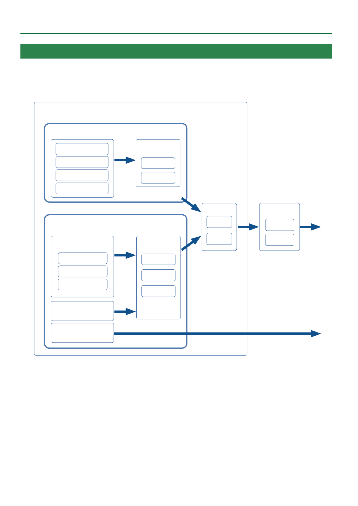
User Program (UPG)
A User Program (UPG) contains tone settings for the four parts that are assigned as the Keyboard Parts (Upper1, Upper2, Upper3, Lower). The style
and song settings, as well as all settings that are loaded with them (for example, the intro and ending status, and settings for the selected variation),
are also handled together within the user program (UPG).
You can store one hundred UPGs as a User Program Set (UPS).
UPG data is managed in units of UPS (.UPS les).
UPG settings data
User Program (UPG)
Keyboard Part
Upper1
Upper2
Upper3
Lower
Keyboard Part
Eects
EQ
MFX
5 Keyboard Part Mixer
5 Style Part Mixer
5 Melody Intelligent
5 Arranger Setting
5 Split
5 Transpose
5 Scale Tune
5 Pad Setting
5 Assignable Setting
5 Other
Intro, Variation, and Ending
status
Auto Fill on/o
Sync Start/Stop on/o
Bass Inversion on/o
Style/Song Part
* Style and Song (SMF, Audio) cannot be played simultaneously.
Style
Style/Song Part
(*)
Chorus
Reverb
Mastering Tools
EQ
Compressor
Eects (*)
ACC1–6
Bass
Drum
EQ
MFX A
MFX B
* Style/Song Eect, Chorus, and
Reverb settings are located in
Makeup Tools.
Song (SMF)
Part 1–16
Song (Audio)
Wav/MP3
Within a user program, the E-A7 can save settings for the style, the song, and the tones.
However, it is not the case that the user program contains the actual data (le) for the style, the song, and the tones; rather, the user program contains
references to these items of data.
For style, song, and phrase data, the user program remembers the location and name of that data.
For example, if, after saving a user program, you then rename, delete, or move a style, the user program will no longer be able to reference the style
data that it originally used. If a user program references style data from a USB ash drive, that style data can’t be referenced if the USB ash drive is
disconnected.
In such cases, you’ll have to return the style data to its original location and name at the time when the user program was saved, or re-select the style.
The same applies to song and phrase data.
For user tone and user drum kit data, the user program remembers the location (tone number) of the data.
If the user program or style uses (contains) a user tone or user drum kit, and you then change the tone number, the tone used when the data was
saved can no longer play. In such cases, you’ll have to return the tone number (location) to its original state at the time that the user program or user
style was saved, or re-select the user tone or user drum kit.
If you want to save or exchange the user data in its entirety, it’s convenient to use Backup/Restore (p. 67).
You can back up data such as user programs, user styles, and user tones from internal storage as a single unit. You can then restore this data to return
to the original state.
However, the data (user programs and user styles) in external storage (USB memory) is not backed-up.
We recommend that you also make a copy of the user data on USB ash drive along with the backup le.
4
Page 5
Eects
The E-A7 contains the following eects units. You can make settings independently for each of them.
MFX (Multi Eects)
This is a general-purpose multi-eect that modies the sound itself, potentially giving it a completely dierent tonal character.
A wide variety of types are provided, and you can choose the type that’s most appropriate for your purpose.
There are a total of three MFX units: one unit dedicated to the keyboard part, and two units for backing.
Chorus
Chorus is an eect that adds depth and spaciousness to the sound. You can choose whether to use this eect unit as chorus or as delay.
The depth of chorus can be adjusted individually for each part.
Reverb
Reverb is an eect that gives the sound a spatial ambience that’s characteristic of a performance in a hall.
Several types are provided, and you can choose the type that’s most appropriate for your purpose.
The depth of reverb can be adjusted individually for each part.
Input EFX
This unit can apply reverb or other eects to the sound from the input jacks.
Mastering Tools
The mastering tools consist of a mastering compressor and equalizer that are applied to all parts.
About the Styles
An Overview of the E-A7
The E-A7 can generate interactive accompaniments based on the style you select.
Styles are assigned to the Style buttons by category, and each Style button is also divided into sub-categories.
In addition to using the internal styles, you can also create your own original styles.
&
“Style Composer” (p. 39)
Style data is a collection of accompaniment patterns (called “divisions”) each consisting of up to eight parts. Based on four accompaniment
variations for dierent energy levels of the main song, they include divisions such as intros, endings, and lls.
By using the panel buttons to switch between these divisions, you can freely create the structure of the song while you perform.
As you perform, the accompaniment changes according to the chords that you play on the keyboard.
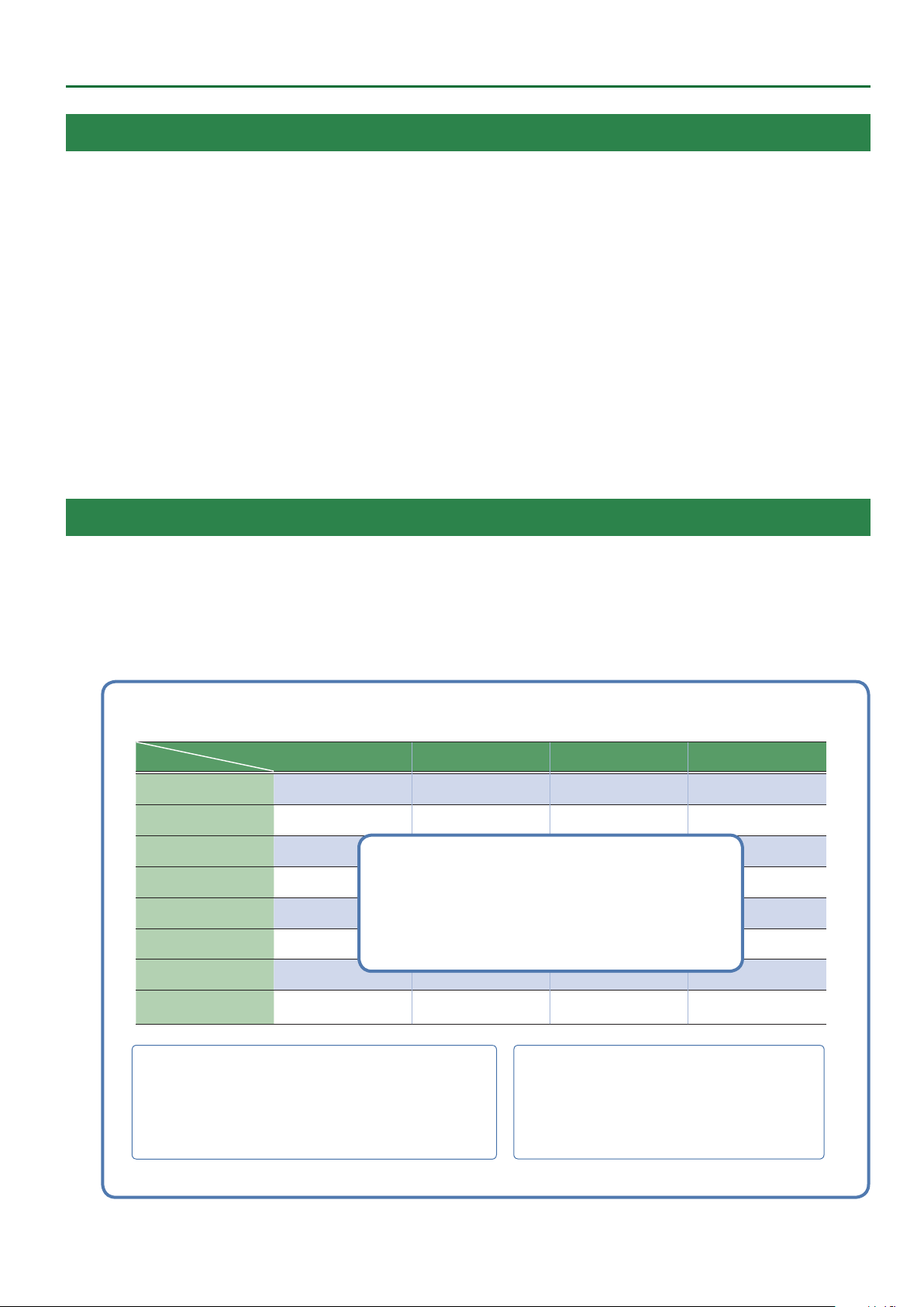
Style
Performance data
Part
Division
ACC1
ACC2
ACC3
ACC4
ACC5
ACC6
Bass
Intro 1–4 Variation 1–4 Fill 1–4 Ending 1–4
Performance data for each Part, each Division
5 Note
5 Program Change
5 Control Change
etc...
Drum
Makeup Tools (various settings) (p. 50)
5 Oset values for Volume and Pan etc.
5 EQ
5 MFX A/B
5 Chorus/Reverb
* These settings are made for each tone or drum kit included in the style.
One Touch 1–4 (p. 23)
One Touch memorizes the settings of the Keyboard Part (such
as Upper1).
Use these when you want to recall performance settings that are
appropriate for the style.
5
Page 6
An Overview of the E-A7
About the Memory
The state of the E-A7’s parameters and the data that you create are held in memory.
This memory is divided into three categories: “temporary memory,” “rewritable memory,” and “non-rewritable memory.”
Temporary memory (Temporary area)
A user program (UPG) that you load during a performance, and the panel settings that you modify while performing, are held in temporary memory
(the temporary area).
When you edit a User Tone or user drum kit, this data is also held in the temporary area during that time.
Settings in the temporary area are temporary, and will be lost when you turn o the power or recall other settings. If you want to keep the settings
that are in the temporary area, you must save them to rewritable memory.
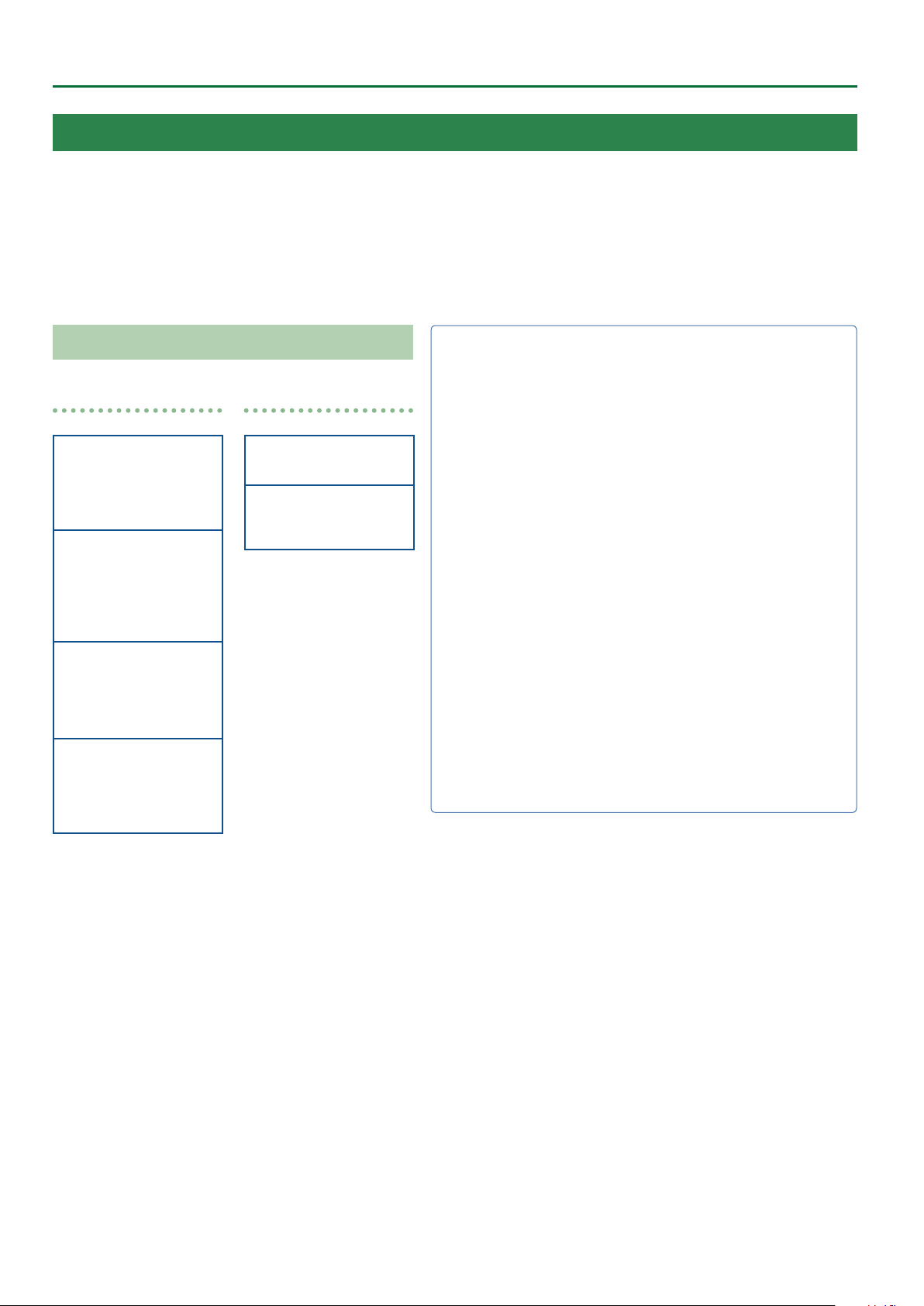
Memory Structure
Data related
Internal Storage
5 UPS (User Program)
5 User Style, Song
5 Phrase
External Storage
(USB Memory)
5 UPS (User Program)
5 User Style, Song
5 Phrase
System Memory
5 Global
5 My Setup
5 Favorite
5 Scale Memory 1–3
Preset Memory
5 Music Assistant
5 Preset Tone / Drum Kit
5 Preset Style
* Non-rewritable memory
etc…
etc…
Wave related
User Sample Memory
5 Sample Wave
Preset Wave Memory
5 Preset (Internal) Wave
* Non-rewritable memory
Internal Storage
The memory that lets you store data inside the E-A7 is called Internal
Storage.
This holds user programs sets (UPS), user styles, User Tone settings, and
user drum kit settings.
External Storage
You can insert a USB ash drive and store data outside the E-A7. Such
external memory (a USB ash drive) is called External Storage, and can
be used in the same way as internal storage.
External storage can also be used as an audio recording destination, or
to back up data.
System Memory
System Memory is located inside the E-A7, and stores system settings
that determine the overall operation of the E-A7.
Preset Memory
This memory holds parameters for the internal sounds, internal styles,
and Music Assistant. Its data cannot be rewritten.
User Sample Memory
This is memory that stores user samples that were captured by sampling
or that were imported by the sample import function.
Preset Wave Memory
This memory contains waveform data used by the internal sounds. Its
data cannot be rewritten.
6
Page 7
Menu Options
By pressing the E-A7’s [Menu] button you can access various settings
and functions.
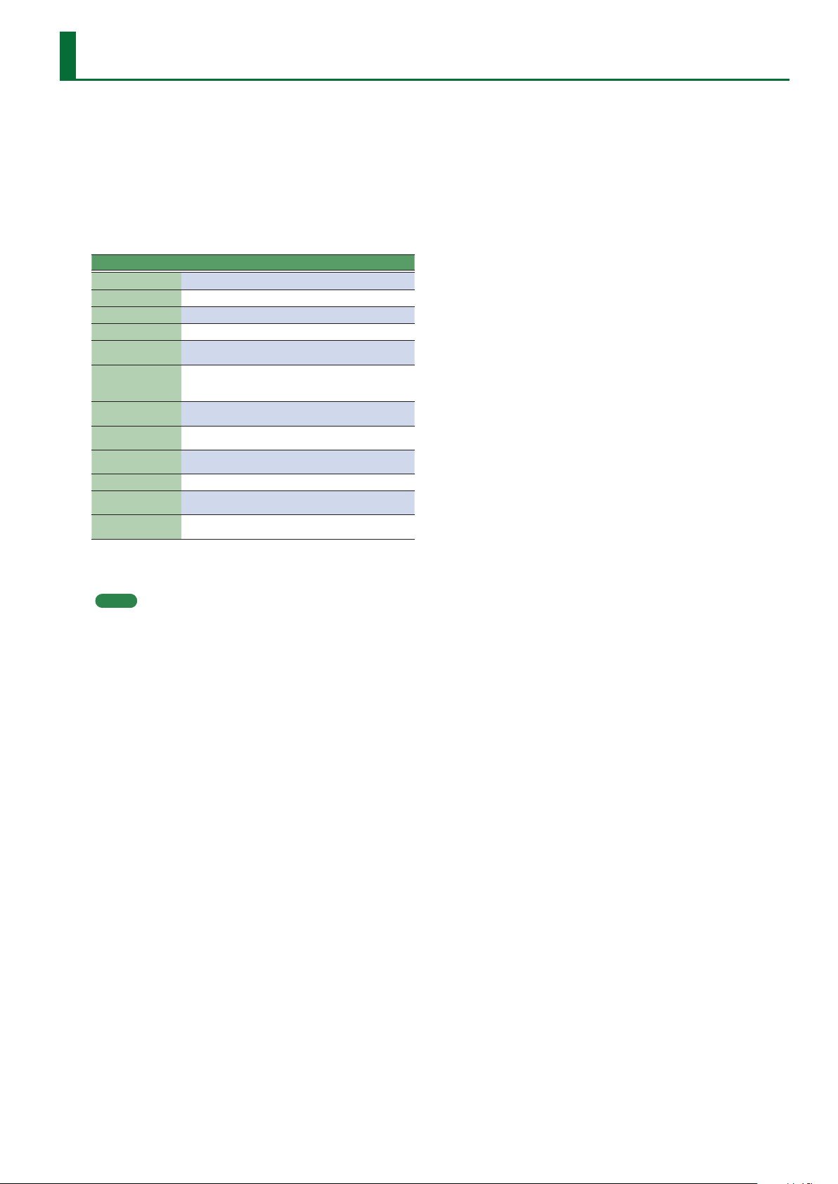
The menu contains the following items.
1. Press the [Menu] button.
The Menu screen appears.
2. Use the direct buttons to select a function or parameter
group.
Switch pages as necessary.
Group Explanation
Global Make settings for the entire E-A7 or for the system.
User Program Edit Make User Program settings.
One Touch Setting Access the One Touch Setting screen.
Sampling Menu Access sampling-related items.
Style Composer
Makeup Tools
SMF Mark&Jump
Lyrics
Mastering Tools
MIDI Make MIDI-related settings.
File Utility
Utility
Access items related to Style Composer.
Style Composer is a function that creates user styles.
Access items related to Makeup Tools.
Makeup Tools are functions for easily editing a style or
SMF.
Access the SMF Mark&Jump function setting screen
(p. 55).
Allow lyric data to be displayed on the E-A7 (limited to
SMF or mp3 les that contain lyric data) (p. 56).
Adjust the compressor and equalizer that are applied
to the output.
Perform operations on the les that are saved in the
E-A7’s internal storage and external storage (p. 66).
Perform operations for the entire E-A7 (such as initialization and backup).
3. In the screen that appears after you make the selection,
edit the parameters or execute the command.
MEMO
5 Press the [Exit] button once to return to the next higher level.
5 Long-press the [Exit] button to return to the Main screen.
5 When the main page is shown in the left display, you can press
the [Option] button located at the left to jump to some of the
functions.
5 When in Style mode
6Style Composer
6Makeup Tools
6One Touch Setting
5 When in Song (SMF) mode
6SMF Mark & Jump
6Makeup Tools
7
Page 8
Global Parameters
The settings of the “Global” parameters can be saved to the E-A7’s
global memory.
Global parameters are automatically saved when you exit the page
or turn o the power.
Style/SMF Track Mute
See “Muting a Specic Track (Track Mute)” on Owner’s Manual: p.
24.
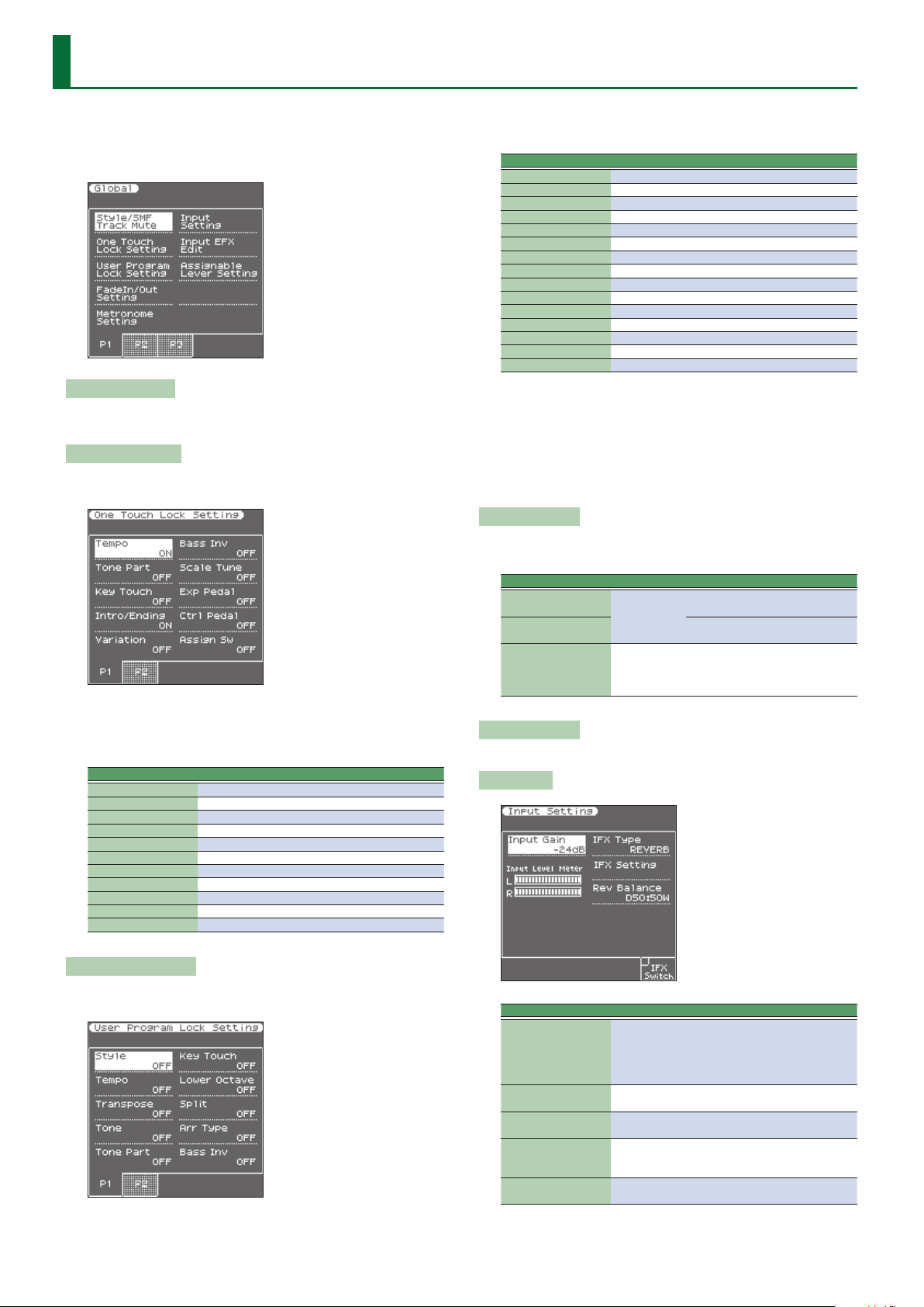
One Touch Lock Setting
This parameter can be selected using [MENU] 0 “Global” 0 “One
Touch Lock Setting.”
The parameters on this page allow you to lter certain “One Touch”
settings. Select “On” for the settings you do not want to load along
with the remaining One Touch settings when you press a ONE
TOUCH button.
Parameter Value
Tempo OFF, ON
Keyboard Part OFF, ON
Key Touch OFF, ON
Intro/Ending OFF, ON
Variation OFF, ON
Bass Inv OFF, ON
Scale Tune OFF, ON
Exp Pedal OFF, ON
Ctrl Pedal OFF, ON
Assign Sw OFF, ON
Pad OFF, ON
along with the remaining settings when you select a User Program
memory.
Parameter Value
Style OFF, ON
Tempo OFF, ON
Transpose OFF, ON
Tone OFF, ON
Keyboard Part OFF, ON
Key Touch OFF, ON
Lower Octave OFF, ON
Split OFF, ON
Arr Type OFF, ON
Bass Inv OFF, ON
Scale Tune OFF, ON
Exp Pedal OFF, ON
Ctrl Pedal OFF, ON
Assign Sw OFF, ON
Pad OFF, ON
5 If the UPG Lock button is enabled (lit), parameters that are turned
on will be locked.
5 If you long-press one of the Style category buttons, the Style is
temporarily locked. If you long-press one of the Tone category
buttons, Tone, Lower Octave, and Key Touch are temporarily
locked. If you long-press the Transpose [+] or [-] button,
Transpose is temporarily locked.
Fade In/Out Setting
These parameters can be selected using [MENU] 0 “Global” 0
“FadeIn/Out Setting.”
Parameter Value Explanation
Time In
0–20s
Time Out
Time Hold 1–10s
Use this parameter to change the
Fade In duration.
Use this parameter to change the
Fade Out duration.
Use this parameter to set how long
it takes for the volume to return to
the master [VOLUME] setting after
completing the fade-out.
Metronome Setting
See “Using the Metronome” on Owner’s Manual: p. 19.
Input Setting
User Program Lock Setting
This page can be selected using [MENU] 0 “Global” 0 “User
Program Lock Setting.”
The parameters on this page allow you to lter certain User Program
settings. Select “On” for the settings you do not want to load
8
Parameter Value Explanation
Adjusts the input gain. If the input
Input Gain -24 dB - 48 dB
IFX Type
IFX Edit
IFX Balance
IFX Switch ([F5]
button)
OFF, REVERB,
DELAY
D100:0W–
D0:100W
sound is not loud enough, raise this
setting. (This adjusts L/MONO, MIC R Input. It does not adjust the EXT IN
input level.)
Selects the type of input eect.
Accesses the edit screen of the eect
that’s selected in IFX Type.
Species the balance between the
original sound (D) and the eect
sound (W).
Turns the input eect on/o.
Page 9
Global Parameters
Parameter Value Explanation
Adjusts the input level. Use the
Input Level Meter
Input Gain and the panel Mic/Line
In Volume to adjust the level so that
the maximum is not reached.
Input EFX Edit
This parameter is not shown if the Input Setting parameter IFX Type
is set to OFF.
If the Input Setting parameter IFX Type is set to REVERB
Parameter Value Explanation
ROOM1,
Reverb Type
Time 0–127 Time length of reverberation
HF Damp (High Frequency Dump)
Rev Balance
Level 0–127
If the Input Setting parameter IFX Type is set to DELAY
Parameter Value Explanation
Delay Type SINGLE, PAN Selects the type of delay.
Delay (Sync) OFF, ON
Delay (msec) 0–2600 msec
Delay (note) Note
Tap Time 0–100%
Feedback 0–98%
HF Damp (High Frequency Dump)
Dly Balance
Level 0–127
ROOM2,
STAGE1,
STAGE2, HALL1,
HALL2
200 Hz, 250 Hz,
315 Hz, 400 Hz,
500 Hz, 630 Hz,
800 Hz, 1000
Hz, 1250 Hz,
1600 Hz, 2000
Hz, 2500 Hz,
3150 Hz, 4000
Hz, 5000 Hz,
6300 Hz, 8000
Hz, BYPASS
D100:W0–
D50:W50–
D0:W100
200 Hz, 250 Hz,
315 Hz, 400 Hz,
500 Hz, 630 Hz,
800 Hz, 1000
Hz, 1250 Hz,
1600 Hz, 2000
Hz, 2500 Hz,
3150 Hz, 4000
Hz, 5000 Hz,
6300 Hz, 8000
Hz, BYPASS
D100:W0–
D50:W50–
D0:W100
Species the type of reverb.
Frequency at which to cut the
high-frequency portion of the reverb
sound.
(BYPASS: no cut)
Volume balance between the direct
sound (D) and the eect sound (W)
Adjusts the volume of the reverb
sound.
If this is on, tempo-synchronized
delay is applied.
Adjusts the delay time.
Adjusts the delay time of the L-channel relative to the R-channel delay
time taken as 100%.
* This can be set if Type = PAN.
Proportion of delay sound that is
returned to the input.
Frequency at which to cut the
high-frequency portion of the delay
sound returned to the input
(BYPASS: no cut).
Volume balance between the direct
sound (D) and the eect sound (W)
Adjusts the volume of the delay
sound.
Parameter Value Explanation
Pitch Bend,
Set1 Horizon
Set2 Horizon
Set3 Horizon
Set4 Horizon
Set5 Horizon
Set1 Vertical
Set2 Vertical
Set3 Vertical
Set4 Vertical
Set5 Vertical
Cuto,
Resonance,
Attack,
Decay,
Release,
Vibrato Rate,
Vibrato Depth,
Vibrato Delay,
Pan
Bend Up,
Bend Down,
Modulation,
Cuto (*),
Resonance (*),
Attack (*),
Decay (*),
Release (*),
Vibrato Rate (*),
Vibrato Depth (*),
Vibrato Delay (*),
Porta Time,
Chorus Send,
Reverb Send,
C1
Select the parameter that is
controlled when you move the
assignable lever horizontally
(left/right).
For details about each value,
refer to the related item in “Key-
board Part Mixer Parameters”
(p. 11).
Select the parameter that is
controlled when you move
the assignable lever vertically
(upward).
[*] These settings produce
change in the “+” direction.
For details about each value,
refer to the related item in “Key-
board Part Mixer Parameters”
(p. 11).
NOTE
When the power is turned on, or when UPG is switched, this is
always set to Assignable Lever Set 1.
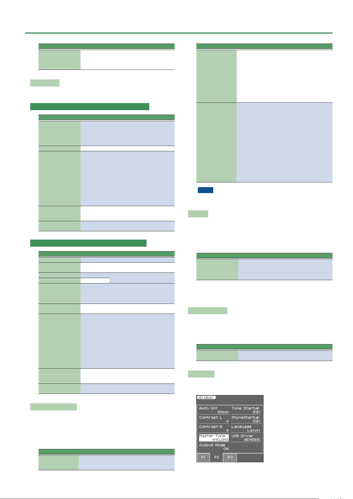
Auto O
This parameter allows you to cause the E-A7 to switch itself o after
the selected number of minutes if you are not using it. The default
setting is “240.” Select “O ” if you prefer not to use this function.
The values in parentheses indicate when the pop-up countdown
appears.
Parameter Value
O,
Auto O
10 (5)
30 (15)
240 (30)
When the E-A7 has been switched o by this function, you need to
press the [POWER] button, wait a few seconds, then press the button
again to switch the E-A7 back on. (Do not switch it on too quickly.)
Display Contrast L/R
This parameter can be selected using [MENU] 0 “Global” 0
“Display Contrast L” or “Display Contrast R.”
It is used to change the contrast of the E-A7’s display in case you nd
it dicult to read.
Parameter Value
Display Contrast L
Display Contrast R
1–10
Master Tune
This parameter can be selected using [MENU] 0 “Global” 0
“Master Tune.”
Assignable Lever Setting
Here you can select the parameters that are assigned to the
assignable lever.
You can specify up to ve sets of parameters that are controlled
when you move the lever horizontally or vertically.
The AsgnLeverSet parameter species which set is assigned to the
assignable lever.
Parameter Value Explanation
AsgnLeverSet 1–5
Select the parameter settings
(1–5) that you want to assign to
the assignable lever.
9
Page 10
Global Parameters
This parameter allows you to tune your E-A7 to acoustic instruments
that cannot be tuned. The default is 440.0 Hz.
Parameter Value
Master Tune 415.3–466.2 Hz
Output Mode
Parameter Value Explanation
Switches the acoustical character of
the sound that is output from the
Phones jack/Output jacks and the
E-A7’s speakers.
ON (When the button is lit):
Settings are optimized for
the response of the E-A7’s
speakers.
OFF (When the button is unlit):
Output Mode OFF, ON
The Mastering Tools function’s
Compressor and Equalizer
settings will be enabled.
The factory settings (Type:
Standard) or the User settings
are applied.
* The “Standard” compressor and equal-
izer type settings are optimal for use
when the Phones jack or Output jacks
are connected to an external speaker
or PA system.
Tone Startup
Parameter Value Explanation
INDONESIA,
VIETNAM, IN-
Tone Startup
DIA, THAILAND,
ORIENTAL,
EGYPT, TURKEY,
EAST EUROPE,
ETHNIC,
FRETTED,
PERCUSSION
Species the tone list that is rst
selected when you press the Tone
category [WORLD] button immediately after turning the power on.
StyleStartup
Parameter Value Explanation
INDONESIA,
VIETNAM,
INDIA, THAI-
StyleStartup
LAND, CHINA,
KHALIGI,
ORIENTAL,
MAGHREBI,
TURKISH,
EAST EUROPE,
LATIN AMERICA, BRAZIL
Species the style list that is rst
selected when you press the Style
category [WORLD] button immediately after turning the power on.
2nd-Bar: Causes playback to start from measure 2 of the selected
Standard MIDI File.
1st-Note: This is basically the same as the above, except that
playback starts on the rst note of the selected song.
UPG NextSong
At the end of the current song, the next song in the UPG List starts
automatically.
If the UPG List step refers to a style, the style in question is loaded,
but you will need to start manually by pressing the [START/STOP]
button.
Parameter Value
UPG NextSong OFF, ON
UP EQ/MfxLink
If you select “on,” the E-A7 selects suitable MFX and equalizer
settings for each Tone you assign to the Upper 1 part.
Parameter Value
UP EQ/MFX Link O, On
Rec Level
Allows you to set the recording level for your own performances (see
p. 41). The setting of the [Master Volume] knob does not aect the
recording level. (Default setting: +0 dB)
Parameter Value
Rec Level -24, -18, -12, -6, 0 dB
RecAudioSync
Parameter Value
Rec Audio Sync OFF, ON
O: Choose this setting when you want to start recording before
starting style or song playback.
On: Choose this setting when you want to be able to start recording
simultaneously with style/song playback. When you choose this
setting, pressing the [REC] button will stop both playback and the
recorder.
Recall MIDI
This parameter selects the MIDI Set whose settings are loaded when
the E-A7 is switched on. Select “O ” if no MIDI Set should be recalled
when the E-A7 is switched on.
Parameter Value
Recall MIDI O, Tone/Style, PK Series, Song, User 1–8
USB Driver
Language
This parameter allows you to choose the character set to be used for
the following:
5 “Finder” functions (Owner’s Manual: p. 44)
5 “Name” function (Owner’s Manual: p. 16)
Parameter Value
Language Latin, Cyrillic, East Europe
SMF QuickStart
Parameter Value
SMF QuickStart O, 2nd-Bar, 1st-Note
O: Playback starts at the very beginning of the song le (which may
contain a few silent bars).
10
Parameter Value
USB Driver GENERIC, VENDOR
GENERIC: Choose this if you want to use the standard USB driver
that was included with your computer. Normally, you should use this
mode.
VENDOR: Choose this if you want to use a USB driver downloaded
from the Roland website (www.roland.com).
Page 11
User Program Edit Parameters
The following parameters can be set for each Performance memory:
Parameter/Group Explanation
Keyboard Part Mixer
Keyboard Part MFX
Style Part Mixer Here you can make settings for the style parts.
Arranger Setting
Melody Intelligent
Split Here you can specify the split point of the keyboard.
Scale Tune Switch
Scale Tune
Pad Setting Here you can make settings for the pads.
Assignable Setting
Here you can make settings for the keyboard parts
(UP1, UP2, UP3, LWR).
Here you can make eect settings for the keyboard
parts (UP1, UP2, UP3, LWR).
This function group allows you to specify where and
how the selected Style should scan the note messages
generated by your playing for chord information.
Here you can make settings for the Melody Intelligent
function.
Melody Intelligent is a function that automatically
adds harmony to the keyboard parts.
Here you can specify the parts for which the Scale
Tune setting is enabled.
Here you can specify how the pitch will be adjusted
in units of one cent (1/100 of a semitone) relative to
equal temperament.
Here you can make settings for the assignable switches and control pedal.
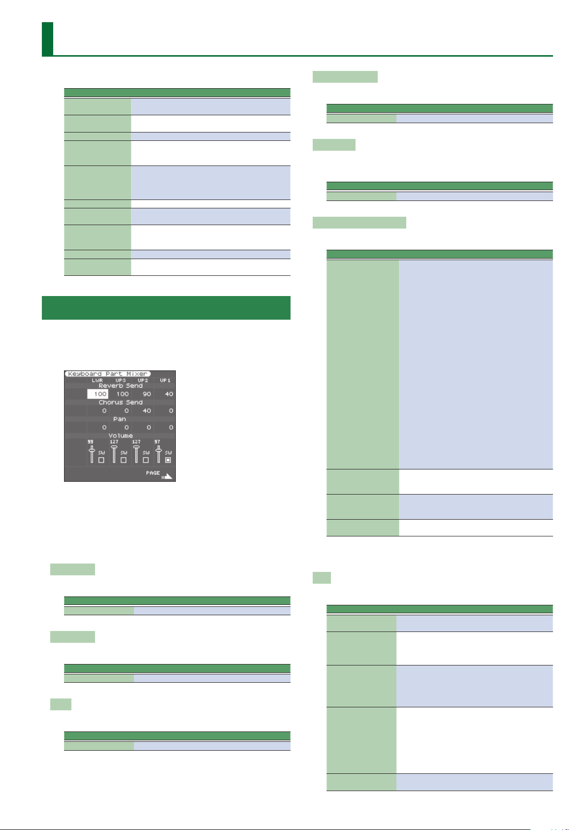
Keyboard Part Mixer Parameters
This function group can be selected using [MENU] 0 “User
Program Edit” 0 “Keyboard Part Mixer.” You can also access the
Keyboard Part Mixer screen by pressing the [F1] button (Kbd Mixer)
of the left main screen.
The vertical columns correspond to each keyboard part (UP1, UP2,
UP3, LWR).
The horizontal rows show parameters that you can edit.
Use the direct buttons and Cursor buttons to select the desired
parameter, and use the Value [-] [+] buttons or the Balance/Value
knob (when the LED is unlit) to edit the value.
The following parameters are available:
Reverb Send
Signal level sent from each part to reverb
Parameter Value
Reverb Send 0–127
Chorus Send
Signal level sent from each part to chorus
Parameter Value
Chorus Send 0–127
Pan
Pan (left/right position) of each part
Parameter Value
Pan L64–0–R63
Volume/Part Switch
Volume and on/o setting of each part
Parameter Value
Volume 0–127
MFX Switch
The E-A7 provides one multi-eect (MFX) for the keyboard parts.
For each part, you can specify whether the MFX is applied.
Parameter Value
MFX Switch O, On
Key Touch (velocity sensitivity)
Here you can make settings for the keyboard touch.
Parameter Value Explanation
High: Select this setting for max-
imum expressiveness. Even small
variations of the force with which
you strike a key produce audible
changes. The trade-o is, however,
that you have to strike the keys
forcefully to reach the maximum
volume.
Medium: Medium velocity sensitivi-
ty.
The keyboard responds to velocity
Key Touch Curve
Key Touch Min 1–126
Key Touch Max 2–127
Key Touch Fixed* 1–127
High, Medium,
Low, Fixed*
changes, but the maximum volume
can be obtained more easily than
with “High.” (This is the default
setting.)
Low: Select this setting if you are
used to playing on an electronic
organ or if you do not want velocity
changes to bring about major volume changes.
Fixed: Select this setting if all notes
you play on the keyboard should
have the same velocity value. When
you set this parameter, the “Key
Touch Fixed” eld can be edited
This parameter allows you to set the
smallest velocity value with which
you can trigger the selected part.
This parameter allows you to set the
highest velocity value with which
you can trigger the selected part.
Allows you to set the value when
“Cur ve” is set to “Fixed.”
[*] This parameter can only be edited if the “Key Touch Curve”
parameter is set to “Fixed.”
EQ
Here you can make equalizer (EQ) settings for each keyboard part.
Parameter Value Explanation
EQ Switch O, On
1500, 2000,
High Freq (Hz)
High Gain (dB) -15–+15
Mid Freq (Hz)
Mid Gain (dB) -15–+15
3000, 4000,
6000, 8000,
12000
200, 250, 315,
400, 500, 630,
800, 1000,
1250, 1600,
2000, 2500,
3150, 4000,
5000, 6300,
8000
This parameter allows you to switch
the equalizer on and o.
Allows you to set the cuto frequency of the high band (this is a shelving
lter).
Use this parameter to set the level of
the selected “High” frequency.
Positive values boost (increase the
volume of) that frequency band,
negative values cut (attenuate) it.
Allows you to set the cuto frequency of the middle band (this is a
peaking lter).
Use this parameter to set the level of
the selected “Mid” frequency.
11
Page 12
User Program Edit Parameters
Parameter Value Explanation
Use this parameter to specify the
Mid Q
Low Freq (Hz)
Low Gain (dB) -15–+15
0.5, 1.0, 2.0,
4.0, 8.0
90, 150, 180,
300, 360, 600
width of the “Mid Frequency” band
that you want to boost or cut. Smaller values mean that neighboring
frequencies above/below that value
are also aected.
Allows you to set the cuto frequency of the low band (this is a shelving
lter).
Use this parameter to set the level of
the selected “Low” frequency.
Expression Pedal
This parameter allows you to specify whether the expression pedal
eect is applied to each part.
Parameter Value
Expression Pedal O, On
Expression Pedal Up/Down
The expression pedal allows you to control the volume of all parts by
foot.
“Up” and “Down” refer to the volume that is used when the
expression pedal is pressed (“Up,” highest volume) or in the upright
position (“Down,” lowest volume).
You do not need to specify “0” for the “Down” position.
Selecting any other values will reduce the volume of the selected
part up to the “Down” value.
Likewise, you do not need to specify “127” as maximum value for
“Up.”
NOTE
The expression pedal sends MIDI Expression commands (CC11).
It is perfectly possible to set the “Down” value to “127” and the
“Up” value to “0,” so that the selected part only sounds when the
expression pedal is in the upright position. This can be used for
some clever eects: instead of alternating between the Upper1
and Upper2 parts by varying your velocity (which requires a
considerable amount of “striking precision,” see “Min Value”
and “Max Value” on p. 11), you could invert UP2’s response to
the expression pedal, so that UP1 doesn’t sound when UP2 does,
and vice versa.
Parameter Value
Expression Pedal Up/
Down
0–127
Hold Pedal
This parameter allows you to specify whether and how a hold/
damper pedal you connect to the PEDAL HOLD socket should
respond to Hold messages (CC64).
Parameter Value
Hold Pedal Auto, On, O
“Au to” means that the part in question only responds to Hold
messages if it is assigned to the right half (Split) or the entire
keyboard.
“On” means that the part in question always responds to Hold
messages, even if it is assigned to the left half of the
keyboard.
“O,” nally, means that the part does not respond to Hold
messages.
Control Pedal
This parameter allows you to specify whether the control pedal eect
is applied to each part.
Parameter Value
Control Pedal O/On
12
Assignable Lever Horizontal
This parameter allows you to specify for each keyboard part how it
should respond to left/right movements of the assignable lever.
Parameter Value
Assignable Lever
Horizontal
Auto, On, O
“Auto”: The keyboard part only responds to left/right movements
of the lever when no split setting causes it to be to the left
of other keyboard parts. In other words: parts you can play
with your left hand after selecting a split no longer respond.
But they will while the keyboard is not split.
“On”: The keyboard part always responds to left/right movements of
the assignable lever.
“O ”: The part in question does not respond to left/right
movements of the assignable lever.
Assignable lever Vertical
This parameter allows you to specify for each keyboard part how it
should respond to backward movements of the assignable lever.
Parameter Value
Assignable lever
Vertical
Auto, On, O
“Auto”: The keyboard part only responds to vertical movements of
the assignable lever when no split setting causes it to be to
the left of other keyboard parts. In other words: parts you
can play with your left hand after selecting a split no longer
respond. But they will while the keyboard is not split.
“On”: The keyboard part always responds to vertical movements of
the assignable lever.
“O ”: The part in question does not respond to vertical movements
of the assignable lever.
Pitch Bend Range
This parameter allows you to specify the amount of pitch change
(in semitone units) that occurs if pitch bend is assigned to the
assignable lever or control pedal.
Parameter Value
Pitch Bend Range 0–24
Octave Shift
Allows you to transpose the selected keyboard part in octave steps.
Parameter Value
Octave Shift -4–0–+4
Coarse Tune
Changes the pitch of the selected keyboard part in semi-tone steps.
Parameter Value
Coarse Tune -24–0–+24
NOTE
You can’t change the Coarse Tune setting of the UP3 part.
Fine Tune
Changes the pitch of the selected part in steps of 1 cent (1/100 semitone).
Parameter Value
Fine Tune -100–0–+100
NOTE
You can’t change the Fine Tune setting of the UP3 part.
Mono/Poly
You can set the selected part to mono(phonic) mode.
Page 13
User Program Edit Parameters
“Mono” means that you can only play one note at a time. You could
select this mode to play a trumpet or woodwind part in a more
natural way.
“Poly,” on the other hand, means that you can play chords using the
selected part.
Parameter Value
Mono/Poly Poly, Mono
NOTE
You can’t change the Mono/Poly setting of the UP3 part.
Portamento Time
“Portamento” means that the pitch doesn’t change in clearly
dened steps: it produces glides from one note to the next. Use the
this parameter to specify the speed at which those glides are carried
out. The higher the value, the slower the transitions.
Parameter Value
Portamento Time 0–127
NOTE
You can’t change the Portamento Time setting of the UP3 part.
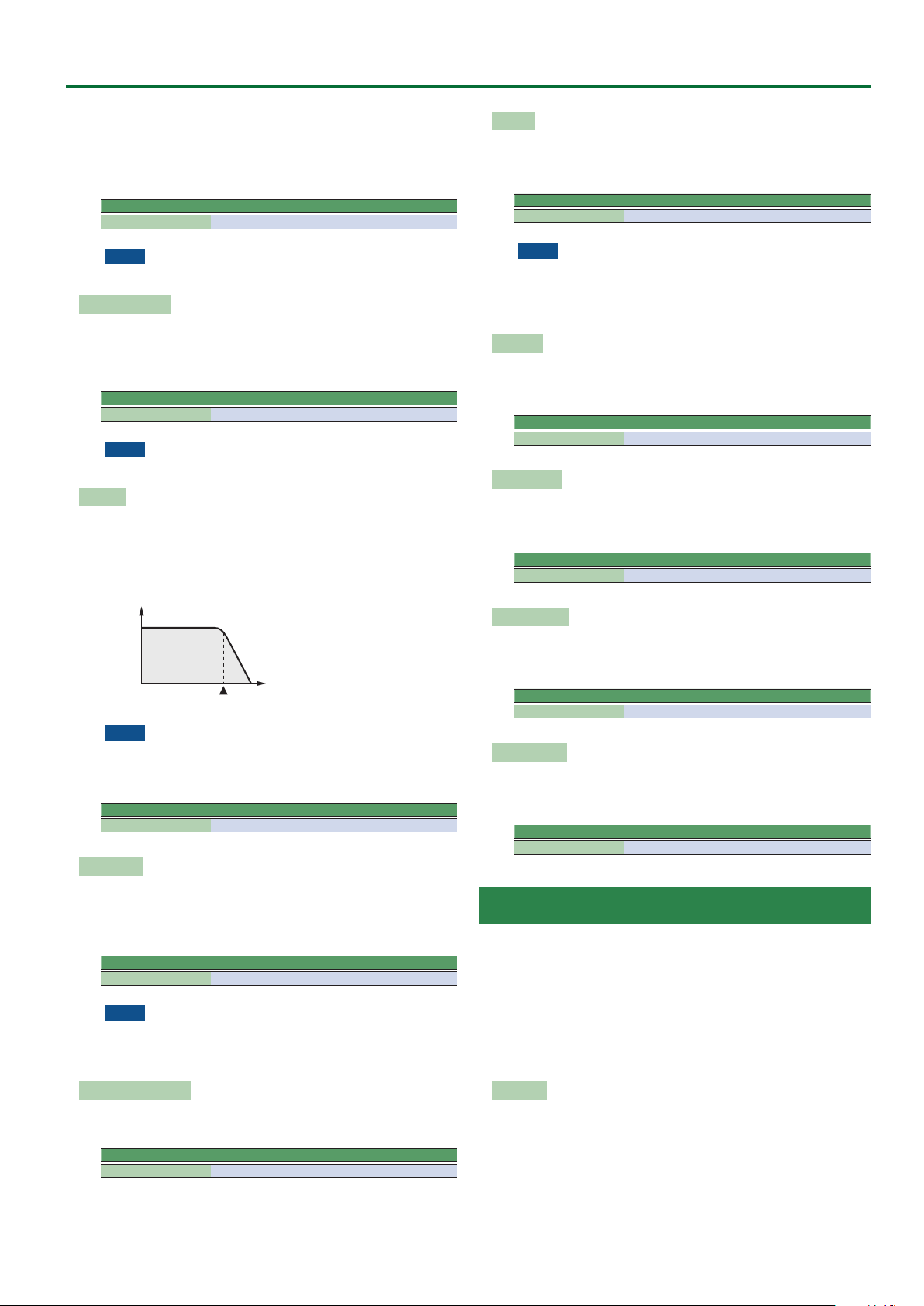
Cut O
This lter parameter allows you to make the selected sound darker or
brighter. Positive settings mean that more overtones will be allowed
to pass, so that the sound becomes brighter. The further this value is
set in the negative direction, the fewer overtones will be allowed to
pass and the sound will become softer (darker).
Setting
Characteristics of a low-pass lter
Frequency
Cuto frequency
NOTE
For some sounds, positive (+) Cuto settings will cause no
noticeable change because the preprogrammed Cuto
parameter is already set to its maximum value.
Parameter Value
Cut O -64–+63
Resonance
Decay
This parameter adjusts the time over which the sound’s volume and
cuto frequency fall from the highest point of the attack down to the
sustain level.
Parameter Value
Decay -64–+63
NOTE
Percussive sounds usually have a sustain level of “0.” Piano and
guitar sounds are in this category. Holding the keys for a long
time will have little eect on the duration of the notes you are
playing, even if you select a high value here.
Release
This parameter adjusts the time over which the sound will decay
after the note is released until it is no longer heard. The cuto
frequency will also fall according to this setting.
Parameter Value
Release -64–+63
Vibrato Rate
This parameter adjusts the speed of the pitch modulation.
Positive (+) settings make the preset pitch modulation faster and
negative (–) settings make it slower.
Parameter Value
Vibrato Rate -64–+63
Vibrato Depth
This parameter adjusts the intensity of the pitch modulation. Positive
(+) settings mean that the “wobble” becomes more prominent,
while negative (–) settings make it shallower.
Parameter Value
Vibrato Depth -64–+63
Vibrato Delay
This parameter adjusts the time required for the vibrato eect to
begin. Positive (+) settings increase the time before vibrato will begin
and negative settings shorten the time.
Parameter Value
Vibrato Delay -64–+63
When the Resonance value is increased, the overtones in the area
of the cuto frequency will be emphasized, creating a sound with a
strong character.
Parameter VALUE
Resonance -64–+63
NOTE
For some sounds, negative (–) “Resonance” settings may
produce no noticeable change because the Resonance is already
set to the minimum value.
Attack (only for Tones)
This parameter adjusts the onset of the sound. Negative values
speed up the attack, so that the sound becomes more aggressive.
Parameter Value
Attack -64–+63
Keyboard Part MFX Parameters
This function group can be selected using [MENU] 0 “User
Program Edit” 0 “Keyboard Part MFX.” Your E-A7 contains a
multi-eects processor that can be used for processing any keyboard
part you like (There are also 2 Mfx processors for the style parts).
Type: Selects the MFX type.
Keyboard MFX Edit: Accesses a page where you can edit the
parameters of the selected MFX.
MFX Switch ([F5] button): Turns MFX on/o. Turn this o if you
don’t want to apply MFX.
Mfx Type
The E-A7 provides 84 dierent multi-eect types, some of which
are combinations of two eects for added exibility. This parameter
allows you to select the desired type. The available types are:
1. Thru
2. Stereo EQ
3. Overdrive
4. Distortion
5. Phaser
6. Spectrum
29. OD 0 Delay
30. DST 0 Chorus
31. DST 0 Flanger
32. DST 0 Delay
33. EH 0 Chorus
34. EH 0 Flanger
57. VK Rotary
58. 3D Chorus
59. 3D Flanger
60. 3D Step Flgr
61. Band Chorus
62. Band Flanger
13
Page 14
User Program Edit Parameters
7. Enhancer
8. Auto Wah
9. Rotary
10. Compressor
11. Limiter 39. CHO/DLY 67. Gate
12. Hexa-Chorus 40. Flanger/DLY 68. Long Delay
13. Trem Chorus 41. CHO/Flanger 69. Serial Delay
14. Space-D 42. Isolator 70. MLT Tap DLY
15. St. Chorus 43. Low Boost 71. Reverse DLY
16. St. Flanger 44. Super Filter 72. Shue DLY
17. Step Flanger 45. Step Filter 73. 3D Delay
18. St. Delay 46. Humanizer 74. Long Time DLY
19. Mod. Delay 47. Speaker Sim 75. Tape Echo
20. 3 Tap Delay 48. Step Phaser 76. LoFi Noise
21. 4 Tap Delay 49. MLT Phaser 77. LoFi Comp
22. Time Delay 50. Inf Phaser 78. LoFi Radio
23. 2 Pitch Shifter 51. Ring Modul 79. Telephone
24. FBK Pitch 52. Step Ring 80. Phonograph
25. Reverb 53. Tremolo 81. Step Pitch
26. Gate Reverb 54. Auto Pan 82. Sympa Reso
27. OD 0 Chorus
28. OD 0 Flanger
35. EH 0 Delay
36. Chorus 0 DLY
37. Flanger 0 DLY
38. CHO 0 Flanger
55. Step Pan 83. Vib-Od-Rotary
56. Slicer 84. Center Canc
63. Band Step Flg
64. VS Overdrive
65. VS Distortion
66. GT Amp Simul
Mfx Edit
The rst two parameters for each Mfx type are “Chorus Send”
(0–127) and “Reverb Send” (0–127). They allow you to specify
whether—and to what extent—the Mfx signal should be processed
by the Chorus and/or Reverb eect.
Style Part Mixer Parameters
This function group can be selected using [MENU] 0 “User
Program Edit” 0 “Style Part Mixer.”
You can also access the Style Part Mixer screen by pressing the [F2]
button (Style Mixer) of the left main screen.
Expression Pedal
Select “O ” if you don’t need pedal expression for the selected part.
This means that the style part in question no longer responds to
an expression pedal you may have connected to the EXPRESSION
socket.
Parameter Value
Expression Pedal O, On
Volume
Adjusts the volume of the selected style part.
Selecting “0” means that the part in question is no longer audible.
Parameter Value
Volume 0–127
Accomp AllO ([F1] button)
Turns o all parts ACC1–6.
Accomp AllOn ([F2] button)
Turns on all parts ACC1–6.
Exp. Pdl AllO ([F4] button)
Turns o the expression pedal connection of all parts Drum, Bass,
and ACC1–6.
Exp. Pdl AllOn ([F5] button)
Turns on the expression pedal connection of all parts Drum, Bass,
and ACC1–6.
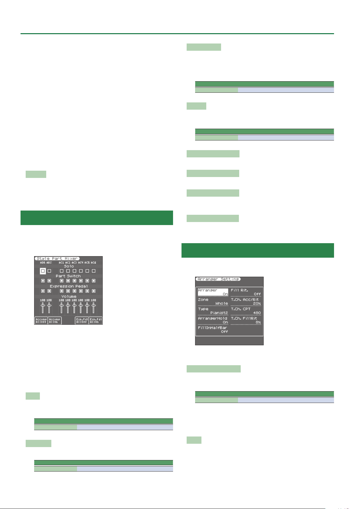
Arranger Setting Parameters
The parameters of this function group apply to the eight Arranger
parts (i.e. the parts used to play back the selected style).
The vertical columns correspond to each style part (ADR is the drum
part, and ABS is the bass part). The horizontal rows show parameters
that you can edit.
Use the direct buttons and Cursor buttons to select the desired
parameter, and use the Value [-] [+] buttons or the Balance/Value
knob (when the LED is unlit) to edit the value.
The following parameters are available:
Solo
Allows you to solo the selected part, which means that all other style
parts are switched o.
Parameter Value
Solo O, On
This function group can be selected using [MENU] 0 “User
Program Edit” 0 “Arranger Setting.”
The parameters of this function group apply to the Arranger as a
whole and allow you to ne-tune its behavior.
Arr Switch (Arranger Switch)
Select “O ” if you only need the drum part of the selected style and
no melodic accompaniment parts (ABass, ACC1–6).
Parameter Value
Arr Switch O, On
You can also turn the arranger switch on/o by pressing the [F5] (Arr
Switch) button of the left main screen.
If you turn the arranger switch O and then On again, chord
detection will resume when you play a chord.
Part Switch
Turns each part on/o.
Parameter Value
Part Switch O, On
14
Zone
When you press the [SPLIT] button, the selected style pattern is
controlled by the chords you play in the left half of the keyboard.
You can also tell the Arranger to scan another part of the keyboard
for usable chords. Though “Left” is probably the most popular
setting, you could select “Right” to have the Arranger scan the right
half of the keyboard.
Page 15
User Program Edit Parameters
Switch o the [SPLIT] button if the Arranger should scan the entire
keyboard (“Whole”).
The range of the left and right keyboard areas depends on the “Split
Point” setting (Owner’s Manual: p. 18).
Parameter Value
Zone O, Left, Right, Whole
Type
Another important choice is how you want to transmit note
information to the Arranger.
Parameter value
Type Standard, Pianist1, Pianist2, Intelligent, Easy
NOTE
If the “Arr Type” parameter (p. 8) is set to “O n,” this “Ty pe”
setting has no eect.
Standard: This is the normal chord recognition mode.
Pianist1: In this mode, the E-A7 only recognizes chords that consist
of at least three notes. Playing only two notes will not cause
the style’s key to change.
Pianist2: Same as “Pianist1” while the Hold pedal is not pressed.
If you press the Hold pedal, the E-A7 even recognizes
“chords” when you press only one note. If the hold pedal is
still pressed, chord recognition continues up to a maximum
of 5 played keys.
Intelligent: Select this option when you want the chord recognition
function to supply the missing notes of the chords you play.
Easy: This is another “intelligent” chord ngering system.
It works as follows:
Major chords
Minor chords
Seventh chords
Minor seventh chords
Press the key that corresponds to the chord’s fundamental.
Fundamental + any black key to the left of the
fundamental.
Fundamental + any white key to the left of the
fundamental.
Fundamental + any black key to the left + any white
key to the left.
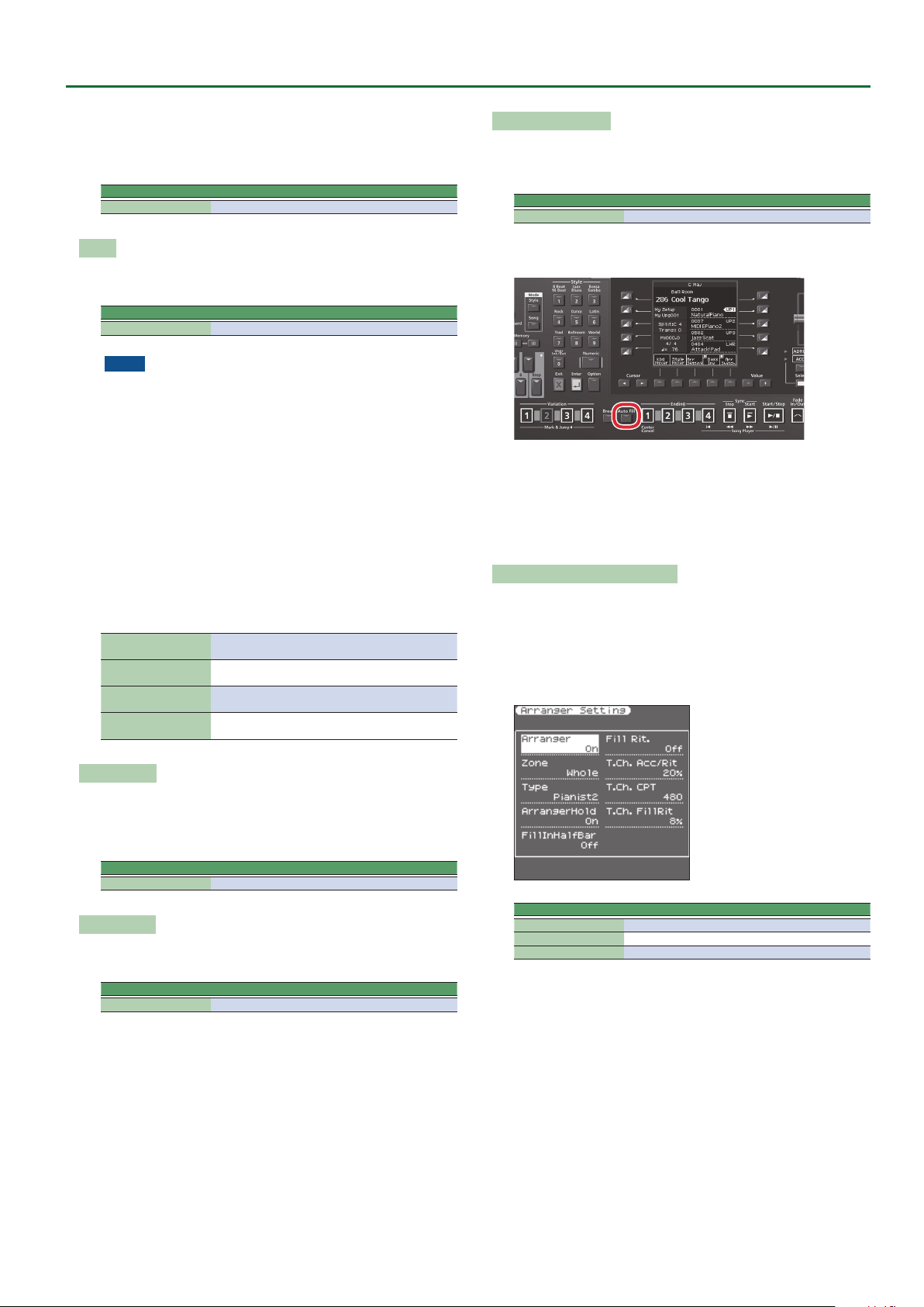
Fill Rit. (Fill Ritardando)
The FILL RIT function is suitable for ballads. It causes the next Fill-In
to slow down (“ritardando”). See “Tempo Change Fill Rit” below
for how to set how strongly the tempo should be decreased.
Parameter Value
Fill Rit. O, On
As the name implies, it is only available while the [AUTO FILL-IN]
button lights.
a. Set “Fill Rit.” to “ On .”
b. Start Arranger playback.
c. Press a VARIATION [1]–[4] button.
The E-A7 plays a Fill-In. The tempo slows down while the ll is
being played. At the end of the ll, return to the original tempo.
Tempo Change Accel/Ritard, CPT, Fill Rit
The “T. Ch. Acc/Rit” (Tempo Change Acceler/Ritard) parameter
allows you to speed up or slow down the style tempo by the amount
you set here. To use these functions, you must assign them to an
optional footswitch (p. 21).
There are three Ritardando functions: one for all style patterns, one
for Ending patterns and one for ll-ins (see “Fill Rit.” above). They all
use the “Tempo Change” settings on the following page.
Arranger Hold
This function sustains the notes you play in the chord recognition
area (“Zone”). Select “O ” if you want the accompaniment to
stop as soon as the keys in that zone are released. This parameter is
switched “On” by default.
Parameter Value
Arranger Hold O, On
Fill In Half Bar
When this parameter is “O n ,” the length of the Fill-Ins, which are
played when the [AUTO FILL IN] button lights, is halved.
Parameter Value
Fill In Half Bar O, On
Certain pop songs in 4/4 contain bars that only last two beats. The
usual place for such a bar is between the rst and the second verse.
Another favorite position for “halved” bars is at the end of a chorus
or the bridge. Your E-A7 allows you to faithfully reproduce these
“anomalies” using this function. This does not change style playback
right away. Only when a ll-in or another VARIATION pattern starts
will the “Fill-in Half Bar” function be activated and play half the
number of beats of the accompaniment pattern you selected.
Parameter Value
T. Ch. Acc/Rit 5%–92%
T. Ch. CPT 0–3825
T. Ch. FillRit 5%–92%
T. Ch. Acc/Rit (Tempo Change Accel/Ritard): Allows you to set the
degree (ratio) by which the tempo changes when the “Acceler” or
“Ritard” function is triggered. Example: if the tempo is currently ¸=
100, the value “20%” means that the tempo drops to ¸= 80 or rises
to ¸= 120.
T. Ch. CPT (Tempo Change CPT): Use this parameter to specify how
long a ritardando/accelerando should take. In most cases, 480 CPT
(i.e. one measure) is probably the most musical choice.
T. Ch. FillRit (Tempo Change Fill Rit): This parameter allows you to
specify to what extent ll-in playback should be slowed down when
the “Fill Ritardando” function is on.
9 Using the Ritardando/Accelerando functions
For general applications (any style division) proceed as follows:
5 Assign the “Arr Rit” or “Arr Acc” function to an optional
footswitch (p. 21).
5 Press the [START/STOP] button to start style playback.
5 Press the assigned footswitch.
15
Page 16
User Program Edit Parameters
For ritardandos that apply to Ending patterns proceed as follows:
5 Press the [START/STOP] button to start playback.
5 Press the [ENDING] button twice in succession (“double-click”).
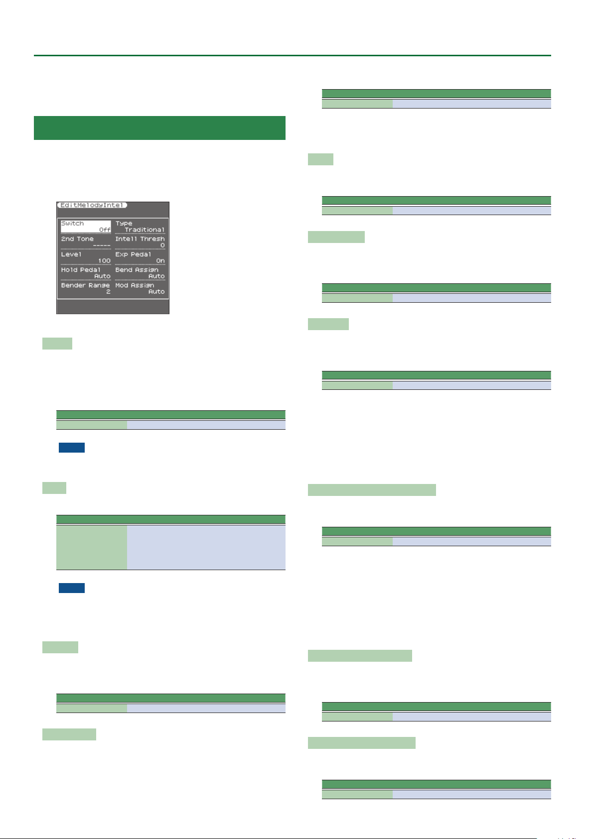
Melody Intelligent Parameters
This function group can be selected using [MENU] 0 “User
Program Edit” 0 “Melody Intelligent.”
The Melody Intelligent part on/o setting and some of the
parameters can also be edited in the Keyboard Part Mixer screen.
&
Keyboard Part Mixer (p. 11)
The following parameters are available:
Switch
Select “On” if you want to add a MELODY INTELL part.
This part is triggered by the chord recognition of the E-A7’s
Automatic Accompaniment and plays automatic harmonies that are
added to the melody that you are playing using the Upper 1 part.
You can choose from among 18 harmony types (see below).
Parameter Value
Switch O, On
NOTE
This “Switch” parameter can also be assigned to an optional
pedal switch. See “Pedal Switch and Pedal Control” (p. 21).
Type
Allows you to select one of the 18 harmony types:
Parameter Value
1: Duet, 2: Organ 3: Combo, 4: Strings, 5: Choir,
Type
NOTE
The most suitable tone for the Type is assigned. When you switch
the Type, this means that the tone of the Upper1 part may also
change. After selecting the desired Type, you can select the
Upper1 tone.
2nd Tone
Depending on the selected “Ty pe” setting, a second harmony is
added to the “Melody Intelligent” part. If you like, you can select
the desired Tone for the second harmony voice using this parameter.
Parameter Value
2nd The Tone of the selected family
6: Block, 7: Big Band, 8: Country, 9: Traditional,
10: Brodway, 11: Gospel, 12: Romance,
13: Latin, 14: Country Guitar, 15: Country Ballad,
16: Waltz Organ, 17: Octave Type1, 18: Octave Type2
If you don’t need this switching function, select “0.”
Parameter Value
Intell Threshold 0–127
The following parameters are valid for the 2nd tone.
Level
Allows you to set the level of the “Melody Intelligent” part to
ensure that the harmonies blend in with the rest.
Parameter Value
Level 0–127
Expression Pedal
This parameter allows you to specify whether or not the “Melody
Intelligent” part should respond to movements of the optional
expression pedal you connected, and change its volume accordingly.
Parameter Value
Expression Pedal O, On
Hold Pedal
This parameter allows you to specify whether or not the “Melody
Intelligent” part’s notes can be held with the pedal switch
connected to the PEDAL HOLD/SWITCH socket.
Parameter Value
Hold Pedal Auto, On, O
“Au to” means that the “Melody Intelligent” part only responds to
Hold messages if it is assigned to the right half (Split) or the
entire keyboard.
“On” means that the “Melody Intelligent” part always responds to
Hold messages, even if it is assigned to the left half of the
keyboard.
“O ” means that the “Melody Intelligent” part does not respond to
Hold messages.
Asgn Lever H (Assignable Lever Horizontal)
This parameter allows you to specify for each keyboard part how it
should respond to left/right movements of the assignable lever.
Parameter Value
Asgn Lever H Auto, On, O
“Auto”: The keyboard part only responds to left/right movements
of the lever when no split setting causes it to be to the left
of other keyboard parts. In other words: parts you can play
with your left hand after selecting a split no longer respond.
But they will while the keyboard is not split.
“On”: The keyboard part always responds to left/right movements of
the assignable lever.
“O ”: The part in question does not respond to left/right
movements of the assignable lever.
Bender Range (Pitch Bend Range)
This parameter species the amount of pitch change (in semitone
units) that occurs if pitch bend is assigned to the assignable lever or
control pedal.
Parameter Value
Bender Range 0–24
Intell Threshold
This value represents the lowest velocity value (between “0” and
“127”) of the Upper 1 part that triggers the “Melody Intelligent”
part.
16
Asgn Lever V (Assign Lever Vertical)
This parameter allows you to specify for each keyboard part how it
should respond to backward movement of the assignable lever.
Parameter Value
Modulation Assign Auto, On, O
Page 17
User Program Edit Parameters
“Auto”: The keyboard part only responds to backward movements
of the assignable lever when no split setting causes it to be
to the left of other keyboard parts. In other words: parts you
can play with your left hand after selecting a split no longer
respond to modulation messages. But they will while the
keyboard is not split.
“On”: The keyboard part always responds to backward movements
of the assignable lever.
“O ”: The part in question does not respond to backward
movements of the assignable lever.
Reverb Send
Level of signal sent to reverb
Parameter Value
Reverb Send 0–127
Chorus Send
Level of signal sent to chorus
Parameter Value
Chorus Send 0–127
Pan
Pan (left/right position)
Parameter Value
Pan L64–0–R63
select “O,” the LWR part stops sounding as soon as you release all
keys in the left area.
Scale Tune Switch
This parameter can be selected using [MENU] 0 “User Program
Edit” 0 “Scale Tune Switch.”
Parameter Value Explanation
Upper1
Upper2
Upper3
Lower O, On
Style O, On
O, On
Select “On” if the “Scale Tune” set-
tings (see below) should apply to the
Upper1 (+ Melody Intell), Upper2,
Upper3 part.
Select “On” if the “Scale Tune”
settings (see below) should apply to
the Lower part.
Select “On” if the “Scale Tune”
settings (see below) should apply to
the Style parts and Pad phrases.
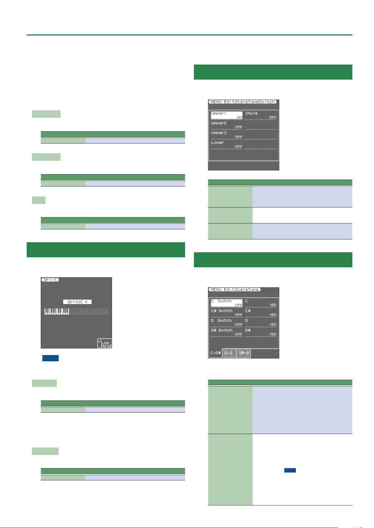
Split
This page allows you to set two keyboard-related parameters. It can
be selected using [MENU] 0 “User Program Edit” 0 “Split.”
NOTE
This page can also be selected by pressing and holding the
[SPLIT] button.
Split Point
The “Split Point” parameter allows you to set the split point.
Parameter Value
Split Point C#2–B6
You can change the split point by using the Value [-] [+] buttons or
the [Balance/Value] knob (when the LED is unlit).
You can also change it by pressing the key that you want to assign as
the split point.
Lower Hold
This parameter allows you to set the Hold function for the LWR part.
Parameter Value
Lower Hold O, On
If you set this parameter to “O n ,” the notes of the LWR part go on
sounding until you play other notes in the left keyboard area. (This
function is only available while the [SPLIT] button lights.) If you
Scale Tune
This parameter can be selected using [MENU] 0 “User Program
Edit” 0 “Scale Tune.”
This parameter allows you to change the tuning of all notes of one
octave, which may come in handy to create oriental tunings.
Parameter Value Explanation
Changes the pitch of the notes C–B
in steps of 1 cent. The value that
C–B
(Each note can be set
individually)
Switch O,On
-64–0–+63
you specify is applied to all notes of
the same name. If you change the
tuning of the “C ,” that value is added
to, or subtracted from, all Cs (C1, C2,
C3, etc.). (“–50” means that the note
in question is tuned a quarter tone
down.)
Species whether the change for
each note is enabled.
The on/o setting for each note can
also be set by using the keyboard
buttons (when the Scale Tune/Pad
LED is lit).
NOTE
The setting and on/o status for
each note is specied and saved for
each UPG.
You can save your favorite tuning
values and use the keyboard buttons
to instantly turn them on/o.
17
Page 18
User Program Edit Parameters
Using Scale Tunings
Your E-A7 allows you to change the tuning of the keys, which then
applies to all notes of the same name.
Here’s an example: if you press the Keyboard [Bb] button (indicator
lights), that note’s tuning is lowered by a quarter tone (–50 cents).
This setting applies to all B-at keys on the keyboard.
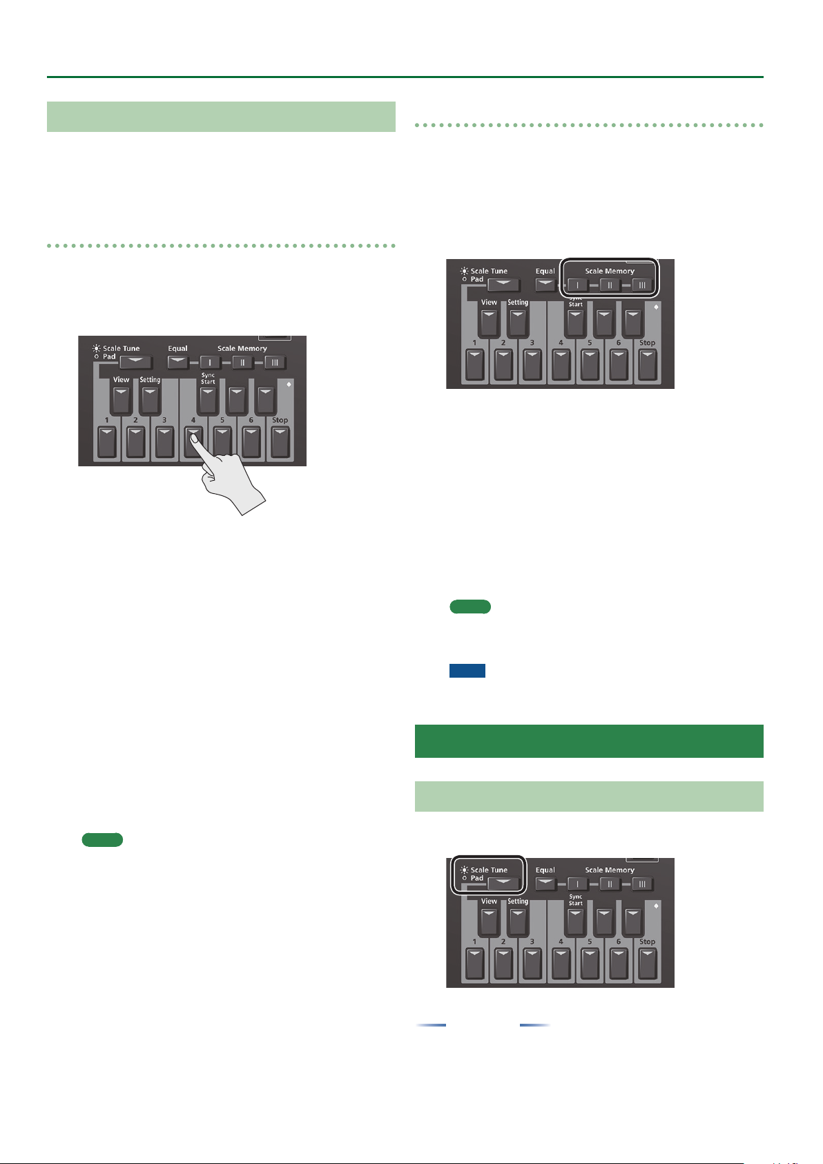
Tuning individual notes a quarter tone down
1. Press the [Scale Tune/Pad] button to make it light.
Now you can use the Keyboard buttons as the Scale Tune buttons.
2. Press a Keyboard button to tune the corresponding
note a quarter tone down (the button must light).
3. If you also want to tune down other notes, press the
corresponding button(s).
If you pressed the wrong button (indicator lights), press it again so
that its indicator goes dark again.
The pitch of the corresponding notes returns to normal.
4. Long-press one of the Keyboard buttons.
The Scale Tune settings screen appears in the right display.
For each note, you can specify how much the tuning will be adjusted
when Scale Tune is enabled (button lit).
You can also access this page via [Menu] 0 “User Program Edit”
0
“Scale Tune.”
5. Use the direct buttons and function buttons (page
buttons) to select the note whose value you want to
change, and use the Value [-] [+] buttons to change the
value.
Setting Range : -64– 63 cents
In this screen you can also switch the Scale Tune setting on/o for
each note.
Use one of the [L1]–[L4] buttons to select a note, and use the Value
[-] [+] buttons to switch the setting on/o.
MEMO
You can save the edited settings in a User Program.
&
“Saving Settings as a User Program” (Owner’s Manual: p.
46)
Saving an edited scale tuning in Scale Memory
A scale tuning that you’ve edited can be saved in a user program or
in Scale Memory 1–3. To recall a scale tuning that you’ve saved, press
a Scale Memory button (to make the button light).
1. Tune the notes to your liking (see p. 17).
2. Press and hold the Scale Memory button ([ I ]–[III]) that
corresponds to the memory where you wish to save
your tuning settings.
3. Wait until all three MEMORY indicators briey light,
then release the button you pressed.
If necessary, you can now select another, Scale memory by briey
pressing the MEMORY button assigned to the settings you wish to
use.
To return to the tuning you were using before selecting a memory,
press the MEMORY button in question again so that its indicator goes
dark, and/or switch o all USER SCALE buttons whose indicators
light.
In the second case, the MEMORY indicator of the last memory
you selected starts ashing to signal that the current USER SCALE
settings no longer correspond to the ones of the last memory you
select. I.e. that memory is still selected, but has since been modied
(“edited”).
MEMO
If you press the [Equal] button (to make the button light), the
scale is set to equal temperament. If you press it again (to make
the button go dark), the scale returns to the previous state.
NOTE
See also “Scale Tune Switch” on p. 17 for deciding which
sections should be aected by the Scale Tune settings.
Pad Setting Parameters
Playing the Pads
When the [Scale Tune/Pad] button is unlit, the keyboard buttons
perform the Pad function.
18
You can use the Pad function to do the following two things.
Play Phrases
Phrases are sequence data for a single part such as guitar strumming
or a shaker.
Phrases are tempo-synchronized with the Style or SMF, and also
support chord detection.
* Phrases will not synchronize with WAV or MP3 songs.
Page 19

User Program Edit Parameters
Play Tones
You can play a specic note number (keyboard location) of a tone.
This is a convenient way to play sound eects or drum sounds.
Playing the Pads
1. Press any one of the Pad [1]–[6] buttons.
A sound or phrase is heard according to the settings of Pad Setting 1.
&
“Editing the Pad Settings” (p. 19)
MEMO
You can play up to six pads simultaneously.
Stopping the Pad Sound
1. Press the Pad [Stop] button to stop all sound.
If multiple pads are sounding, pressing one of the sounding pad
buttons stops the sound of only that pad button.
If you press a pad button while a tone is sounding, the tone begins
sounding again.
Pad Settings
Viewing the Pad Settings
1. With the [Scale Tune/Pad] button unlit, press the View
button.
The Pad Assign View screen appears.
In this screen you can view the phrases or tones that are assigned to
each pad.
Editing the Pad Settings
1. With the [Scale Tune/Pad] button unlit, press [Setting]
button.
The Pad Setting screen for the selected pad appears.
If you want to switch the Pad number, select “Pad number” with
direct button, then use the Value [-] [+] buttons.
MEMO
You can also access this via [Menu] 0 “User Program Edit”
0
“Pad Setting.” You can also access from “Pad Assign View”
screen.
2. Use the direct buttons to select Pad Type.
3. Use the Value [-] [+] buttons to edit the Pad Type.
Pad Type Explanation
O No assign
Phrase A phrase is assigned to Pad
Tone A tone is assigned to Pad
MEMO
5 The setting items dier depending on the Pad Type.
5 If you specify O, pressing that pad does not produce sound.
4. Use the direct buttons to make other settings.
The following items are available for each Pad Type.
Phrase
Parameter Value Explanation
Phrase Phrase Name Select a Phrase.
Volume 0–127 Volume of the phrase.
Reverb Send 0–127 Adjusts the reverb send amount.
Chorus Send 0–127 Adjusts the chorus send amount.
Parameter Value Explanation
MFX O, Mfx, A, B
Loop O, On
Sync Switch O, On
Sync Start O, On
Selecting a Phrase
If you select the Phrase parameter, the Phrase List screen appears.
Use the direct buttons to select a phrase.
MEMO
You can switch Sync Start setting On/O, when you hold down
the Pad [Sync Start] button and press the Pad [1]–[6] button.
* Valid only when the Pad Type is set to Phrase.
Select the routing to Eect
Mfx: Eect used on Keyboard Parts
A or B: Eect used on Accomp Parts
If this is On, the phrase continues playing
repeatedly.
If this is On, the phrase starts at the beginning of measure divisions in the Arranger
or SMF.
If this parameter set ON, Style and SMF
playback start then also begins to ring
Phrase at the same time.
While Style and SMF stop, Pads what this
param set ON is blinking.
Tone
Parameter Value Explanation
Tone
Note 0 (C-)–127 (G9) Note number
Velocity 1–127 Velocity
Volume 0–127 Tone volume
Reverb Send 0–127 Adjusts the reverb send amount.
Chorus Send 0–127 Adjusts the chorus send amount.
MFX O, Mfx, A, B
Hold On, O
MEMO
In the case of a tone, you can’t specify Loop or Sync.
Selecting a Tone
If the Pad Type is set to Tone, the Tone List screen appears in the right
display.
Use the direct buttons of the right display to select a Tone.
You can also select a user tone or user drum kit.
However you might not hear any sound if the sample has been
deleted or if the user tone number has changed.
Tone Num,
Name
Tone number, name
Select the routing to Eect
Mfx: Eect used on Keyboard Parts
A or B: Eect used on Acomp Parts
Holds the sound.
MEMO
A sample that is set to Loop On can be played
continuously (Loop setting: p. 19). A short audio
phrase or a drum pattern can be imported as a
sample, and then assigned to a tone so that you
can play it from the pads.
5. When you have nished making settings, press the
[Exit] button several times to return to the previous
screen.
Saving the Pad Settings
Pad settings are saved in a user program or in a One Touch memory.
&
“Saving Settings as a User Program” (Owner’s Manual: p. 46)
&
“Creating Your Own One Touch Memories (One Touch
Settings)” (Owner’s Manual: p. 26)
Normally, when the Write operation is executed, it will be saved as a
User Program parameters.
NOTE
If one of the One Touch settings is selected (one of the One Touch
[1]–[4] buttons lit), writing a user program will save the One
Touch settings to the user program (the Pad settings are also
included).
19
Page 20
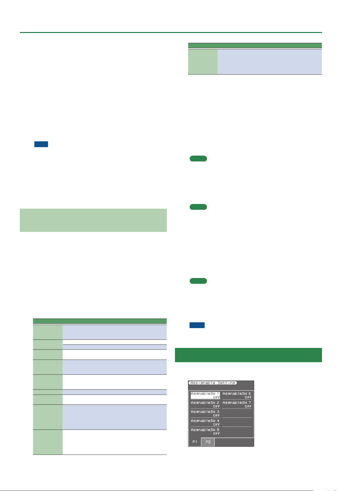
User Program Edit Parameters
If you want to save it as a One Touch memory parameters, execute
the save operation in the following procedure.
1. Call the One Touch you want to change the Pad setting
by One Touch [1]–[4] button.
2. Change the Pad Setting.
3. When nished making changes, enter the One Touch
Setting screen.
&
“Editing and Saving the One Touch Settings of a Style”
(Owner’s Manual: p. 26)
Edit mark is attached to the One Touch that is currently selected.
4. Press the [Option] button.
5. Use the direct buttons to select “Save Style.”
&
“Editing and Saving the One Touch Settings of a Style”
(Owner’s Manual: p. 26) 0 “Step 7” (Owner’s Manual: p. 27)
Note
5 If you want to save the Pad setting in One Touch, rst call the One
Touch you want to change. If you recall a dierent One Touch
memory while editing a One Touch memory, the state of your
editing is lost.
5 If a phrase or tone is assigned in the pad settings, the UPG or One
Touch remembers only the link to that phrase or le.
This means that if the link-destination le cannot be found, for
example because you renamed, deleted, or moved the user
phrase, or disconnected the external storage, no sound is heard.
Creating a Phrase to Play from a Pad (Phrase Recording)
You can create your own original phrases.
To create an original phrase, use the Phrase Recording function.
Here’s how to use the Phrase Recording function.
1. Press the Setting button.
The Pad Setting screen appears.
Select the Pad (Pad Number) to which you want to assign the
recorded phrase.
If Pad Type is not set to “Phrase,” select “Phrase.”
2. Press the [Rec] button.
Phrase Recording Standby screen appears.
If you decide to cancel, press the [Rec] button once again.
3. Use the direct buttons to make settings.
Parameter Value Explanation
Phrase Type
Rec Mode
Tempo 20–250
Octave –4–+4
Key
Tone Tone Name Tone name
Time Signature 1/16, 1/4–4/4...
Measure
Length
Count In
Drum, Bass,
Accomp
New New recording
Mix Mix recording
C, C#, D, Eb, E,
F, F#, G, Ab, A,
Bb, B
O, 1–16
O, 1Meas,
2Meas, Wait
Note
Species the type of phrase that will be
recorded. In the case of Drum, you can’t
select the “Key” parameter.
Species the tempo at which the phrase is
recorded.
Species the octave of the recorded part,
shifting it to the region in which you want
to perform.
Sets the KEY in which the phrase is performed while recording. The key of Drum
Kit parts cannot be set.
Sets the time signature. (selectable only if
Rec Mode is set to New)
Species the number of measures in the
phrase.
If this is O, the measure length is set
automatically according to the length that
you record, up to 16 measures.
Species how long the count-in should be
before recording starts.
Wait Note: Recording starts as soon as you
play a note on the keyboard. (There will be
no count-in.)
Parameter Value Explanation
O, 1/4, 1/8,
Input Quantize
Selecting a Tone
When you select a tone, the Tone List screen of the part selected for
the pad is shown in the right display.
Use the Tone [0]–[9] buttons and the direct buttons of the right
display to select a tone.
1/8T, 1/16,
1/16T, 1/32,
1/32T, 1/64
Corrects minor timing problems.
It shifts the notes whose timing is not
exactly right to the nearest “correct” unit.
Always select a resolution value that is ne
enough to accept all note values you play.
4. Press the [Start/Stop] button to start recording.
5. Perform a phrase.
6. Press the [Start/Stop] button once again to stop
recording.
The phrase save screen appears.
MEMO
If Measure Length is specied, recording stops automatically at
the measure length that you specied.
If you use Mix recording, loop recording occurs.
7. Use the [R1] (Int/Ext) button to switch the copy-
destination between Internal Storage and External
Storage.
MEMO
The Phrase le is placed in the “My Phrases” folder. If this folder
does not exist, it is created automatically. The “My Phrases”
folder exists in both internal storage and external storage.
8. Press the [Enter] button.
Assign a name.
&
For details on assigning a name, refer to “Assigning Names”
(Owner’s Manual: p. 16).
If you decide to cancel, press the [Exit] button.
9. Press the [F5] (Exec) button.
The phrase is saved.
MEMO
If there is already a le with the same name as the name you
entered, a screen asks you to conrm the overwrite.
If you want to save, select “YES” to replace it with the le you
renamed.
If you decide to rename the le, select “NO” and return to the
page where you can rename the le.
NOTE
The phrase does not play if the Arranger Switch is O, nor if
Arranger Hold is O.
Assignable Setting Parameters
This parameter can be selected using [MENU] 0 “User Program
Edit” 0 “Assignable Setting.”
Here you can specify the parameters that are assigned to the
assignable switches and the control pedal.
20
Page 21
User Program Edit Parameters
Pedal Switch and Pedal Control
You can connect two types of Pedal Switch to the E-A7’s CONTROL
jack (Not Continuous or Continuous).
The “Not Continuous” pedal (e. g. DP-2) has only two states: O and
On.
The “Continuous” pedal (e. g. DP-10) has more states between On/
o.
The E-A7 recognizes the type of pedal switch you connect to the
CONTROL jack:
Pedal Switch Jack
Type
The function that you can assign changes depending on the pedal
you connect.
If a Not Continuous pedal is connected, the parameter specied by
“CtrlPedalSW” is enabled. If a Continuous pedal is connected, the
parameter specied by “CtrlPedalCont” is enabled.
Parameter Value Explanation
AsgnableSW 1
AsgnableSW 2
AsgnableSW 3
AsgnableSW 4
AsgnableSW 5
AsgnableSW 6
AsgnableSW 7
CtrlPedalSW
(*): CtrlPedalSW only
How E-A7 recognizes the pedal switch
Mono Type: Not Continuous
Stereo Type: Continuous
O O
Start/Stop
Intro 1–4
Ending 1–4
Variation 1–4
Bass Inv.
Arr. Hold
Arr. ChordO
FillInHalfBar
Break Mute Turns the [Break] button on/o.
Starts and stops style or song playback. Same function as the [START/
STOP] button.
Same functions as the [INTRO],
[ENDING], [VARIATION1], [VARIATION2], [VARIATION3], [VARIATION4], [BASS INV] buttons.
Allows you to switch the Arranger
Hold function on and o. See page
15.
Allows you to switch the Arranger’s
chord recognition o, in which case
only the drum/percussion part is
played.
This is linked with the Arr Switch on/
o setting.
Allows you to switch the “Fill In
Half Bar” function on and o. See
page 15.
Parameter Value Explanation
This function allows you to have the
E-A7 start on the rst beat of the currently selected Style pattern when
you press the assigned switch.
Use it when you are accompanying
a singer or soloist whose timing is a
little shaky and suddenly notice that
the playback lags one or two beats
behind the singer/soloist.
Allows you to assign the selected
Scale Tune (see p. 17) setting to the
three Upper parts.
Allows you to assign the selected
Scale Tune (see p. 17) setting to the
Lower part.
Allows you to switch o the UPPER 1
part and activate the UPPER 2 part–
and vice versa.
NOTE
If neither [UPPER1] or [UPPER2]
buttons are on when you rst press
the Assign Switch button, one of
them is activated.
Allows you to select the next or
previous User Program.
Pressing the switch activates the
“Portamento Time” setting. When
the switch is released, the “Porta-
mento Time” setting is not used.
To hear this eect, you need to set a
“Portamento Time” value (p. 13).
The assigned footswitch can be used
as a Soft, Sostenuto or Sustain (Hold
pedal).
The switch is assigned to the “Lower
Hold” function (see p. 17).
Same function as the [TRACK MUTE]
button.
If an MP3 or WAV le is playing, this
turns Center Cancel on/o.
The switch can be used to activate a
crossfade between two les.
To make this work, select a dierent
song while the current song is being
played back and press the switch.
The E-A7 creates a brief blend
between the current and the next
song. (This function is only available
between two audio songs.)
Fading in means that the volume of
both the style and Keyboard parts
gradually increases, giving the impression that you have been playing
for a long time before what you play
becomes audible. The volume is
automatically set to zero and then
gradually increased to the value
specied with the [VOLUME] knob.
To change the Fade In time duration
see “Fade In/Out Setting” (p. 8)
This function gradually decreases
the volume until it reaches zero. At
that time, song or style playback
stops automatically.
Allows you to control the “Switch”
parameter of the “Melody Intelli-
gent Parameters” (p. 16)
Allows you to switch the MFX for the
keyboard parts on and o.
Allows you to activate the Arranger’s
“Tempo Change Accel/Ritard, CPT,
Fill Rit” (p. 15).
Allows you to activate the Arranger’s
“Tempo Change Accel/Ritard, CPT,
Fill Rit” (p. 15).
Allows you to select the slow or fast
speed of the Rotary eect.
AsgnableSW 1
AsgnableSW 2
AsgnableSW 3
AsgnableSW 4
AsgnableSW 5
AsgnableSW 6
AsgnableSW 7
CtrlPedalSW
(*): CtrlPedalSW only
Reset/Start
Split Turns the [Split] button on/o.
Scale Upper
Scale Lower
Change Upper
UPG Up
UPG Down
Portamento
Mono/Poly Switches between mono/poly.
Hold (*)
Soft (*)
Sostenuto (*)
Lower Hold
Track Mute
AudioXfade
Fade In
Fade Out
MelodyIntelli
Mfx Switch
Arr. RitTempo
Arr. AccTempo
RotSlow/Fast
21
Page 22

User Program Edit Parameters
Parameter Value Explanation
Piano/Std
AsgnableSW 1
AsgnableSW 2
AsgnableSW 3
AsgnableSW 4
AsgnableSW 5
AsgnableSW 6
AsgnableSW 7
CtrlPedalSW
(*): CtrlPedalSW only
CtrlPedalCnt
UPG Lock Turns the UPG Lock button on/o.
Pad 1–6
Pad Stop Stops playback for all pads.
Scale Equal
Scale Memory
1–3
ScaleTune C–B
Lever Set 1–5
Tap Tempo
Bend Up Raises the pitch.
Bend Down Lowers the pitch.
Modulation Applies modulation.
Cuto
Resonance
Attack
Decay
Release
Vibrato Rate
Vibrato Depth
Vibrato Delay
Porta Time
Chorus Send
Reverb Send
C1
By pressing the Assign Switch
button, you alternate between the
“Standard” and “Pianist2” Style Ar-
ranger type (p. 15). When the former
is selected, the chord recognition
area is automatically set to “Left.”
When you switch to Piano Style, the
chord recognition area is automatically set to “Whole.” Furthermore,
the Upper 1 part is activated (if it
was o).
Plays the phrase or sound eect
that’s assigned to the pad.
Sets the Scale Tune to equal temperament.
Recalls “Scale Memory I–III.”
Turns on/o the Scale Tune setting
of each note.
Assigns the parameter specied by
the Assignable Lever Setting (Set
1–5) to the assignable lever.
You can reach the Assignable Lever
Setting via [Menu] button “Global.”
Changes the tempo of the current
style or song according to the interval at which you press the button.
For details on the function of each
value, refer to the corresponding
item in “Keyboard Part Mixer
Parameters” (p. 11).
* To allow the parameter assigned to the control pedal to aect
each keyboard part, turn on the Control Pedal switch on the
Keyboard Part Mixer.
22
Page 23

One Touch Setting
By using One Touch memories you can quickly select performance
settings that are appropriate for the atmosphere of the current style.
There are four One Touch memories for each Style.
Selecting a One Touch Memory
1. Select the desired Style (Owner’s Manual: p. 22).
2. Press the One Touch [1]–[4] buttons.
Canceling the One Touch Memories
1. Press the lit One Touch [1]–[4] button to make it go
dark.
The One Touch function is canceled, and you return to the settings
prior to using the One Touch memory.
Locking One Touch Memories Settings (One Touch Lock)
Several settings can be locked so that they do not change when you
select a One Touch memory.
1. Press the [Menu] button.
2. Use the direct buttons to select “Global.”
3. Use the direct buttons to select “One Touch Lock
Setting.”
The One Touch Lock Setting screen appears.
4. Use the direct buttons to select the items that you want
to lock.
Use the Value [-] [+] buttons to turn the setting on/o.
MEMO
This setting is automatically saved when you exit the screen.
The selected button lights.
MEMO
If you have not yet selected a One Touch memory since you
powered-on the E-A7, the One Touch [1]–[4] buttons are unlit.
If you have selected a One Touch memory even once, the One
Touch memory of the number you selected is automatically
recalled even if you change styles.
3. Play back the Style (Owner’s Manual: p. 21).
4. Play a melody on the keyboard.
5. Press a dierent One Touch [1]–[4] button.
6. Once again, play a melody on the keyboard.
A dierent tone is selected according to the newly selected One
Touch memory. When you select a One Touch memory, Style settings
are also selected as well as a tone.
MEMO
5 By long-pressing a One Touch [1]–[4] button, you can check
the keyboard part tone and part switch settings of One Touch
memories 1–4.
5 The E-A7 has a function that lets you lock specic settings
when you select a dierent One Touch memory. For details,
refer to “Locking One Touch Memories Settings (One Touch
Lock)” (p. 23).
Creating Your Own One Touch Memories (One Touch Settings)
One Touch memories are saved in the style.
Changes that you made to a One Touch memory can be saved as a
user style.
For preset styles as well, if you’ve edited the One Touch memory, you
can save the settings to internal storage or external storage as a user
style.
Editing and Saving the One Touch Settings of a Style
1. Select the desired Style (Owner’s Manual: p. 22).
2. Press the One Touch [1]–[4] button whose settings you
want to edit.
3. Edit the settings.
One Touch memories can store the state of the panel buttons and
the state of the style.
4. Long-press a One Touch [1]–[4] button.
The screen changes as follows.
You can also access this page via [Menu] 0 “One Touch Setting.”
If the left display shows the Style main page, you can also access this
page by pressing the [Option] button and then pressing the [L2]
(One Touch Setting) button.
23
Page 24

One Touch Setting
MEMO
When you edit the One Touch settings, the screen indicates
“EDITED” to indicate this.
5. Press the [Option] button.
6. Use the direct buttons to select “Save Style.”
7. Use the direct buttons and the function buttons to
select the writing destination.
Button Explanation
[R1] (Int/Ext)
[F4] [F5] (Page) Switch pages.
[L1] Up folder Exits the folder.
Normally, the My Styles folder in Internal Storage is selected.
Switches between Internal Storage and External
Storage.
8. Press the [Enter] button.
Assign a name.
&
For details on how to assign a name, refer to “Assigning Names”
(Owner’s Manual: p. 16).
If you decide to cancel, press the [Exit] button.
9. Press the [F5] (Exec) button.
The style is saved.
MEMO
If there is a le with the same name as the name you entered, a
screen asks you to conrm the overwrite.
If you want to save, select “YES” to replace it with the le you
renamed.
If you decide to rename the le, select “NO” and return to the
page where you can rename the le.
MEMO
After the settings are saved, the user Style that you saved is
selected as the Style.
NOTE
If you recall a dierent One Touch memory while editing a One
Touch memory, the state of your editing is lost.
3. Press one of the [L1] [L2] [L4] [L5] buttons to move the
cursor to the copy-destination One Touch memory.
4. Save the Style via [Option]
The current (copy-source) One Touch settings are copied to the One
Touch memory that’s selected by the cursor.
0
“Save Style.”
Copying a User Program or One Touch Memory to Another One Touch Memory
Copying a User Program to a One Touch Memory
Here’s how to copy user program settings to a One Touch memory.
1. With no One Touch memory selected (i.e., when all of
the One Touch [1]–[4] buttons are unlit), open the One
Touch Setting screen.
2. Press one of the [L1] [L2] [L4] [L5] buttons to move the
cursor to the One Touch memory to which you want to
copy the user program.
3. Save the Style via [Option]
The current user program settings are copied to the One Touch
memory that’s selected by the cursor.
Copying One Touch settings to another One Touch
Memory
Here’s how to copy One Touch settings to another One Touch
memory.
1. Press a One Touch [1]–[4] button to select the copy-
destination One Touch memory.
2. The One Touch Setting screen opens.
0
“Save Style.”
24
Page 25

Sampling Menu
Overall Workow
The E-A7 lets you add new waveforms and play them from the keyboard as pitched sounds.
You can also freely add the sounds of specic ethnic instruments and local instruments.
The following diagram shows the overall workow for creating new sounds.
Obtaining Waveforms
Sampling
You can sample audio waveform data from a mic or audio playback
device via the E-A7’s INPUT jacks directly into a user sample.
Save
User Sample
Reference
Creating a Tone from the User Sample
&
“Creating a User Tone” (p. 29)
Sample import
You can import WAV format waveform data (44.1 kHz, 16 bit, WAV
format only) from external storage (USB ash drive).
&
“Importing Samples” (p. 26)
Save
The waveform data that you sample or import is saved as a user
sample.
A “multisample” is a set of dierent samples assigned to each note of
the keyboard (p. 28).
Reference
Creating a personalized Drum Kit
&
“Creating a User Drum Kit” (p. 33)
User Tone Edit
You can assign a pitch to the added waveform (user sample)
and edit it so that it can be played from the keyboard. You
can also make your keyboard playing dynamics aect the
color of the sound, and you can edit other tone parameters.
Obtaining Waveforms
Here’s how you can directly sample audio waveform data from a mic
or external audio playback device connected to the E-A7’s INPUT
jacks.
Alternatively, you can import a WAV format le from a USB ash drive
into User Sample Memory.
You can use the sampled waveform data to create a tone or drum kit
p. 29, p. 33).
(
User Sample
A user sample is waveform data that was obtained by sampling or by
importing a sample.
User Drum Kit Edit
You can create an original drum kit by editing the drum inst
that are assigned to the drum kit, or by assigning an another
user sample.
Connecting an External Device
* Before you connect an external device, set the Mic/Line In
[Volume] knob to the minimum position, and turn the [Input
ON] button o (unlit).
1. Set the rear panel input switch.
LINE: If connecting an audio device or keyboard
MIC: If connecting a microphone
* If the switch is set to the Mic position, the signal that’s input to
the Input R jack is ignored. The same signal is input to both the R
and L sides.
2. Connect your external device to the INPUT jacks.
* If connecting a microphone, connect it to the L/MONO, MIC jack.
Condenser microphones are not supported.
3. Press the [Input On] button to turn on external input.
The button lights. To turn it o, press the button once again to make
it go dark.
4. Use the Mic/Line In [Volume] knob to adjust the volume
of the input.
25
Page 26

Sampling Menu
5. If you want to apply an eect to the input, press the
[Input EFX] button to turn it on.
The button lights. For more about the input eects, refer to “Input
Setting” (p. 8).
Sampling
1. Press the [Sampling] button.
The Sampling Menu screen appears (you can also access this via the
Menu).
2. Press the [L1] (Sampling) button.
The Sampling Standby screen appears.
Input Level Meter
The input level is shown. Use the input volume to adjust the input level
so that the sound does not distort.
Free memory capacity
The display shows the amount of
free memory in which samples can
be saved. If the memory capacity is
used up during sampling, sampling
ends.
Parameter Value Explanation
Specify whether sampling is done in stereo
or monaural.
Mono sampling takes only half the amount
Stereo Switch Mono, Stereo
Auto Trigger ON, OFF
Auto Trig Level 1–10
Rec Level
-24, -18, -12, -6,
0 dB
3. Press the [F5] (Start) button to start sampling.
MEMO
5 If Auto Trigger is ON, sampling starts automatically when input is
detected.
5 Depending on the Auto Trigger Level setting, the beginning of
the sound might be cut o. In this case, lower the Auto Trigger
Level setting.
4. Press the [F5] (Stop) button to stop sampling.
The Sample Edit screen appears.
NOTE
The sampled data is discarded if you select another sample
without saving the sampled data. Be sure to save important
samples.
of memory.
MONO: The sound is sampled as a single
waveform. The left and right channels of stereo sound are mixed.
STEREO: The sound is sampled as two
waveforms, L and R.
If Auto Trigger is ON, sampling starts automatically when sound input is detected.
If Auto Trig is ON, specify the volume at
which sampling starts.
1–10 (1 is the minimum)
Rec level
Importing Samples
Audio les (WAV format, 44.1 kHz/16-bit only) can be imported from
a USB ash drive into the E-A7.
1. Place the audio les on your USB ash drive in the
following folder structure.
(Root)
–IMPORT
–TEST1.wav
–TEST2.wav
–TEST3.wav
–TEST4.wav
–TEST5.wav
MEMO
Create a folder named “IMPORT” and place the les to be imported in that folder.
If you use the E-A7 to format a USB ash drive, an “IMPORT” folder
is created.
2. Connect the USB ash drive to the E-A7.
3. Press the [Sampling] button.
The Sampling Menu screen appears (you can also access this via the
Menu).
4. Press the [L2] (Sample Import) button.
The audio les inside the IMPORT folder are listed.
5. Use the direct buttons to select the le that you want to
import.
MEMO
You can select multiple les.
If you select [F1] (Select All), all of the les are selected. Press the
button again to clear the selection of all les.
6. Press the [Enter] button.
The E-A7 imports the selected le(s). When import is completed, the
Sample List screen appears.
NOTE
5 Import may take several minutes if you’re importing multiple les
or if the le size is large. Never turn o the power while the screen
indicates “Executing...”
5 Import is not possible if sample memory is full.
5 If there is insucient free memory for Sample Import, a message
asks whether you want to Optimize.
5 When you compare the original sampled or imported sound
to the sound that’s played back by the E-A7, you may notice a
dierence in the character of the sound.
This is due to the settings of the E-A7; the character of the sound
may be aected by settings such as the eect settings of each
part, or the compressor and EQ settings of the Mastering Tools.
5 In order for an imported sound to be played from the keyboard, it
must rst be edited.
Sample Editing
1. Press the [Sampling] button.
The Sampling Menu screen appears (you can also access this via the
Menu).
2. Press the [R1] (Sample List) button.
The Sample List screen appears.
3. Use the direct buttons to select the sample that you
want to edit.
MEMO
By using the direct buttons to select a sample and pressing the
[F3] (Preview) button, you can audition that sample.
4. Press the [Option] button.
The Sample Option screen appears.
5. Use the direct buttons to select “Edit.”
26
Page 27

Sampling Menu
START LOOP END
The Sample Edit screen appears.
6. Edit the sample.
Use the direct buttons to select the parameter that you want to edit.
Use the Value [-] [+] buttons to edit the value. Alternatively, you can
use the [Balance/Value] knob (when the Value function is active /
LED unlit) to edit the value.
Page Button Explanation
[F1] (Zoom H -) Zooms-out horizontally.
[F2] (Zoom H +) Zooms-in horizontally.
[F3] (Preview) Auditions the currently-edited sample.
[F5] (Page+) Moves to the next page.
[L3] (Sample Number) Displays the sample number.
[L4] (Zoom V +) Zooms-in vertically.
[L5] (Zoom V -) Zooms-out vertically.
[R3] (Start Point)
1
[R4] (Loop Start)
[R5] (End Point)
[F5] (Page -) Moves to the previous page.
[R3] (Original Key)
[L3] (Loop Mode)
This is the playback start point. By
editing this you can skip an unwanted
portion at the beginning of the waveform so that the sample starts at the
right moment.
This is the point at which repeated
playback (the second and subsequent
plays) will start. Set this if you want to
loop from a point that is dierent than
the start point.
This is the playback end point. By
editing this you can omit an unwanted
portion at the end of the sample.
Species the note number that plays
the sample at its original pitch. C0–B8
Turns loop playback on/o.
If the loop start position has been
specied
After the Sample played back from
START to END, it will then be repeatedly
played back in the forward direction,
from the LOOP to END.
10. Press the [Enter] button.
A conrmation message appears.
11. To save, select “ Ye s.”
If you want to change the save-destination, select “No” to return to
the page where you can specify the save-destination.
NOTE
If a sample already exists in the save-destination, the previous
sample is deleted.
If you want to keep that sample, use the UST Export or UDK
Export function to save it (p. 33, p. 37).
Deleting a Sample
1. Press the [Sampling] button.
The Sampling Menu screen appears (you can also access this via the
Menu).
2. Press the [R1] (Sample List) button.
The Sample List screen appears.
MEMO
By using the direct buttons to select a sample and pressing the
[F3] (Preview) button, you can audition that sample.
3. Press the [Option] button.
The Sample Option screen appears.
4. Use the direct buttons to select “Delete.”
5. Use the direct buttons to select the sample that you
want to delete.
MEMO
You can select multiple samples.
If you choose [F1] (Select All), all samples are selected. Press the
button again to clear the selection.
6. Press the [Enter] button.
A conrmation message appears.
7. Use the function buttons to select “YES.”
The sample is deleted.
If you decide not to delete, select “NO.”
2
[R4] (Sample Gain)
[R5] (Sample Level)
MEMO
A sample or multisample can be played from the keyboard while
you edit it. In this case, the sample or multisample is assigned to
the UP1 part. The sound will be aected by the eect settings of
the UP1 part, by the Split status, and by the on/o status of the
other parts.
7. To save the sample, press the [Write] button.
A screen appears in which you can name the sample.
&
“Assigning Names” (Owner’s Manual: p. 16)
If you decide to cancel, press the [Exit] button.
8. Press the [F5] (Exec) button.
9. Use the direct buttons and function buttons to select
the save-destination.
Adjusts the gain of the sample.
0, +6, +12 dB
NOTE
In some cases, raising Sample Gain will make
the sound clip (distort).
Adjusts the volume of the sample.
0–127
27
Page 28

Sampling Menu
Creating a Multisample (Create Multisample)
A “multisample” is a set of dierent samples assigned to each note
of the keyboard. One multisample lets you assign up to 128 samples
that are split (divided) across the notes of the keyboard.
You can’t listen to a multisample unless it’s assigned to a tone. When creating a
multisample, you start by selecting multiple samples to create the multisample,
and then assign the multisample to a tone for use.
If you want to change the save-destination, select “No” to return to
the page where you can specify the save-destination.
NOTE
If there is a multisample in the save-destination, the original
multisample is overwritten.
The multisample is created, and the multisample list appears.
Use the multisample to create a user tone or user drum kit (
33
).
MEMO
You can access the multisample list via the Sampling Menu
screen.
p. 29, p.
If, for example, only one note (e.g., the sound of the C4 key) is sampled from a
wide-ranging instrument such as a piano, and assigned to the entire range of
keys, it will sound unnatural when played signicantly below or above its original pitch. If the instrument is sampled at several dierent pitches and assigned
to dierent ranges of the keyboard, this unnatural eect can be minimized.
128 split
(128 key)
sample No.0001
original key
C3
In the Create Multisample function, the split points are automatically determined according to the original key of each sample.
Before you begin this process, you should set the original key of each sample to
the range where you want it to be assigned.
sample
No.0002
original key
C4
split point split point
sample No.0003
original key
C5
7 : original key
1. Press the [Sampling] button.
The Sampling Menu screen appears (you can also access this via the
Menu).
2. Press the [R1] (Sample List) button.
The Sample List screen appears.
MEMO
By using the direct buttons to select a sample and pressing the
[F3] (Preview) button, you can audition that sample.
3. Press the [Option] button.
The Sample Option screen appears.
4. Use the direct buttons to select “Create Multisample.”
5. Use the direct buttons to select samples.
MEMO
You can select multiple samples.
If you choose [F1] (Select All), all samples are selected. Press the
button again to clear the selection.
6. Press the [Enter] button.
The multisample is created.
A screen appears in which you can name the multisample.
&
“Assigning Names” (Owner’s Manual: p. 16)
If you decide to cancel, press the [Exit] button.
7. Press the [F5] (Exec) button.
8. Use the direct buttons and function buttons to select
the save-destination.
9. Press the [Enter] button.
A conrmation message appears.
10. To save, select “ Ye s.”
28
Multisample Editing
1. Press the [Sampling] button.
The Sampling Menu screen appears (you can also access this via the
Menu).
2. Press the [R2] (Multisample List) button.
The Multisample List screen appears.
3. Use the direct buttons to select the sample that you
want to edit.
4. Press the [Option] button.
The Multisample Option screen appears.
5. Use the direct buttons to select “Edit.”
The Multisample Edit screen appears.
6. Use the keyboard or the cursor buttons to select the
Sample (Key) that you want to edit.
You can perform the following operations.
Operation Explanation
Split K J Changes the split point.
Org Key
Erase
Assign
Select You can specify a region by pressing two keys.
MEMO
You can play the sample or multisample from the keyboard while
you edit it. In this case, the sample or multisample sounds as if
it is assigned to the UP1 part. The sound is aected by the eect
settings of the UP1 part, the Split setting, and the on/o status of
other parts.
7. To save the multisample, press the [Write] button.
A screen appears in which you can name the multisample.
&
“Assigning Names” (Owner’s Manual: p. 16)
If you decide to cancel, press the [Exit] button.
8. Press the [F5] (Exec) button.
9. Use the direct buttons and function buttons to select
the save-destination.
10. Press the [Enter] button.
A conrmation message appears.
11. To save, select “ Ye s.”
If you want to change the save-destination, select “No” to return to
the page where you can specify the save-destination.
Changes the original key.
A window appears, allowing you to change the original key.
Use the Value [-] [+] buttons to change the setting.
If you change the original key, the change is saved in the
sample when you write the multisample. If you exit without
saving, the setting reverts to the previous key.
Note that if the same sample is used by other multisamples,
they will also be aected by the change.
Deletes the selected sample from the multisample.
* Although the sample will no longer be referenced by the multisam-
ple, the sample itself will remain.
Assigns the sample to the selected key.
Select the sample to be assigned from the sample list.
Page 29

Sampling Menu
NOTE
If a multisample already exists in the save-destination, the
previous multisample is deleted.
If you want to keep that sample, use the UST Export or UDK
Export function to save it (p. 33, p. 37).
Deleting a Multisample
1. Press the [Sampling] button.
The Sampling Menu screen appears (you can also access this via the
Menu).
2. Press the [R2] (Multisample List) button.
The Multisample List screen appears.
3. Press the [Option] button.
The Multisample Option screen appears.
4. Use the direct buttons to select “Delete.”
5. Use the direct buttons to select the multisample that
you want to delete.
MEMO
You can select multiple multisamples. If you press [F1] (Select All),
all multisamples are selected. Press the button again to clear the
selection.
6. Press the [Enter] button.
A conrmation message appears.
7. Use the function buttons to select “YES.”
The multisample is deleted.
If you decide not to delete, select “NO.”
Although the sample will no longer be referenced by the
multisample, the sample itself will remain.
Each partial can be turned on/o individually, allowing you to select
which partials will be heard.
Tone
Partial
1
Example 1: A tone consisting of a single partial
Partial
2
(Partials 2–4 are turned o)
Partial
3
Partial
4
Tone
Partial
1
Example 2: A tone consisting of four partials
Partial
2
Partial
3
Partial
4
Partial
The partial is the smallest unit of sound. However, it’s not possible
to play just a partial by itself. The unit of sound used for performing
is the tone, and partials are the materials from which a tone is
constructed.
Partial
LFO 2LFO 1
User Tone
On the E-A7, you can use user samples and multisamples to create
your own original tones (User Tones).
You can also edit an internal tone (Preset Tone) and save it as a User
Tone).
In this manual we will sometimes abbreviate “User Tone” as “UST.”
NOTE
5 Some of the internal tones can’t be edited. (The screen indicates
“Can’t edit this tone.” and you are unable to enter the edit
screen.)
5 Tones with an “E” symbol shown at the right of the tone number
in the tone list screen can be edited.
5 When you edit the settings of a tone, the “E” symbol is replaced
by an “*” symbol. When you save the tone settings, the “*”
symbol disappears.
5 If you turn o the power, select another tone, or enter the sample
or multisample edit screen, the changes you made are lost. If you
want to keep the changes you made, you must save the settings.
Check the tone list to see whether you can edit a tone.
How a tone is structured
A tone is the unit of sound used for performing. Each tone consists of
up to four partials.
WG TVF T VA
Pitch
Envelope
Audio signals
WG (Wave Generator)
This selects the waveform (wave) that is the basis of the sound,
and species how the pitch will change.
TVF (Time Variant Filter)
This species change in the frequency response of the sound.
TVA (Time Variant Amplier)
This species change in volume and pan.
Envelope
An envelope species a change over time.
LFO (Low Frequency Oscillator)
An LFO species cyclic change (modulation).
5 There are two LFOs, and each can be used to apply an eect to
the WG (pitch), TVF (lter), or TVA (volume).
5 Using the LFO to apply change to the WG pitch produces a
vibrato eect, applying change to the TVF cuto frequency
produces a wah eect, and applying change to the TVA volume
produces a tremolo eect.
TVF Enve-
lope
TVA En-
velope
Control signals
Creating a User Tone
On the E-A7, you can use user samples and multisamples to create
your own original sound (User Tone). Here’s how to create a new User
Tone.
29
Page 30

Sampling Menu
* User Tone is sometimes abbreviated as UST.
1. In the Tone section, press the [User] button.
The User Tone list appears.
5 Each time you press the [User] button, the contents of the list
switch between UST and UDK.
2. Use the direct buttons to select the Tone that you want
to edit.
MEMO
If you want to create a new user tone, select “Empty.”
3. Press the [Option] button.
The UST Option screen appears.
4. Use the direct buttons to select “Edit.”
The UST Edit screen appears.
On the E-A7, one tone consists of four elements of sound (Partial
1–4).
For each of these partials, you can change the waveform (Wave) and
specify the keyboard region in which it will produce sound.
Use the cursor buttons or direct buttons to select the parameter that
you want to edit, and use the Value [-] [+] buttons to edit the value.
Alternatively, you can edit the value by using the [Balance/Value]
knob (when the Value function is active / LED unlit).
6. Press the [F5] (Exec) button.
7. Use the direct buttons and function buttons to select
the save-destination.
8. Press the [Enter] button.
A conrmation message appears.
9. To save, select “ Ye s.”
If you want to change the save-destination, select “No” to return to
the page where you can specify the save-destination.
NOTE
If there is a user tone in the save-destination, the original user
tone is overwritten.
User Tone Parameters
The following parameters can be edited.
Common parameters
These parameters apply to the entire tone.
The list of Common parameters appears when you press the [F1]
(Common) button in the Tone Edit screen.
Partial parameters
These parameters can be edited for each individual partial.
The list of Partial parameters appears when you press the [F2]
(Partial) button in the Tone Edit screen.
Parameter Value Explanation
Partial Switch ON, OFF Partial on/o
Wave Group
Wave No. L
(Mono)
Wave No. R
Key Range Lower C-1–UPPER
Key Range Upper LOWER–G9
Velocity Range
Lower
Velocity Range
Upper
INT, SAMPLE,
MULTISAMPLE
OFF, 1 -
1–UPPER
LOWER–127
Group of the waveform (Wave) to assign
to the partial
INT: Internal tone waveforms
SAMPLE: Sample waveforms
MSAM: Multisample waveforms
* If you select samples, the pitch won’t
change for keys more than two octaves
away from the original key.
Selects the waveform. Along with the
wave number, the wave name is also
shown in the lower part of the screen.
If you want to use mono, specify only
the left side (L). If you want to use stereo, specify the right side (R) as well.
* If you use a multisample in stereo, specify
the same number for L and R.
* If you use a sample in stereo, you should
likewise specify the same wave for L and R.
For each partial, species the lowest key
of the range in which it will sound.
For each partial, species the highest
key of the range in which it will sound.
Species the lowest keyboard playing
strength that will sound the partial.
Make this setting if you want to use
keyboard playing strength to switch
between partials.
Species the highest keyboard playing
strength that will sound the partial.
Make this setting if you want to use
keyboard playing strength to switch
between partials.
Tone Common
Item/Parameter
Tone Level 0 - 127 Tone volume
Octave Shift -3 - +3 Tone pitch (in octave units)
Tone Coarse
Tune
Tone Fine
Tune
Legato
Switch
Legato
Retrigger
Portamento
Mode *1
Portamento
Type *1
Value Explanation
-48 - +48 Tone pitch (in semitone units, ± 4 octaves)
-50 - +50
OFF, ON
OFF, ON
NORMAL,
LEGATO
RATE, TIME
Tone pitch (in units of 1 cent = 1/100th of a semitone)
Species whether LEGATO SW is used (ON) or not
used (OFF). LEGATO SW is eective if the Keyboard
Part Mixer’s Mono/Poly parameter is set to “MONO.”
If LEGATO SW is “ON,” and you press another key
while a previous key is still held down, the pitch
smoothly changes to the newly-pressed key while
maintaining the continuity of that note.
This lets you obtain eects similar to the hammering-on or pulling-o techniques of a guitarist.
Species whether the note is retriggered (ON) or not
retriggered (OFF) when you play legato. Normally
you’ll leave this “ON.”
LEGATO RETRIGGER is eective if the Keyboard Part
Mixer parameter Mono/Poly is set to “MONO” and
LEGATO SW is turned “ON.”
If this is “OFF,” only the pitch will change when
you press another key while still holding down the
previous key, and the attack of the later-played note
will not be heard.
You should use the “OFF” setting when playing
phrases on a wind instrument or bowed string
instrument sound, or when simulating a mono synth
keyboard.
NORMAL: Portamento is always applied.
LEGATO: Portamento is applied only when you play
legato.
RATE: The speed of the pitch change is xed (the
time occupied by the pitch change is proportional
to the distance between the pitches).
TIME: The time of the pitch change is xed (unaf-
fected by the distance between the pitches).
For details on other parameters, refer to the “User Tone
Parameters” (p. 30) later in this manual.
5. To save the User Tone, press the [Write] button.
A screen appears in which you can name the user tone.
&
“Assigning Names” (Owner’s Manual: p. 16)
If you decide to cancel, press the [Exit] button.
30
Page 31

Sampling Menu
Portamento Start: NOTEPortamento Start: PITCH
C5
D4
C4
press C4 key
press D4 key
Pitch
Time
press C4 key
press C5 key
Portamento Start: NOTEPortamento Start: PITCH
Time
press C4 key
Frequency
TVF Envelope
Time
Item/Parameter
Value Explanation
PITCH: If you press another key while the pitch is
changing, new portamento starts from the pitch
that was sounding at the moment you pressed the
key.
Pitch
C5
D4
C4
press D4 key
Portamento
Start *1
PITCH,
NOTE
press C5 key
NOTE: New portamento starts from the note at
which pitch change ended.
Pitch
C5
D4
C4
press D4 key
press C5 key
Cuto
Oset *2
-63 - +63 Frequency at which the lter begins to take eect.
Amount by which the sound in the region of the
Resonance
Oset *2
-63 - +63
cuto frequency is boosted, giving the sound a
distinctive character.
If this is raised excessively, oscillation might occur,
causing the sound to distort.
Attack Time
Oset *2
-63 - +63
Release
Time Oset *2-63 - +63
Time from when the key is pressed until the attack
is completed
Time from when the key is released until the sound
disappears
Tone Partial
Item / Parameter
Partial
Switch
WG
Modies the pitch of the waveform or sound.
Wave
Group
Wave No.L
(Mono)
Wave
No.R
Wave
Gain
Pitch
Coarse
Tune
Pitch Fine
Tune
TVF
The lter cuts a specic frequency region, modifying the brightness or
thickness of the sound.
Value Explanation
OFF, ON Partial on/o
Group of the waveform (wave) that is assigned to the
INT,
SAMPLE,
MULTISAMPLE
partial
INT: Internal tone waveforms
SAMPLE: Sample waveforms
MSAM: Multisample waveforms
* If you select Sample, the pitch will not change for keys that
are more than two octaves above the original key.
Selects the waveform. Together with the wave
number, the wave name is also shown at the bottom
of the screen.
OFF, 1 -
-6, 0, +6,
+12 [dB]
-48–+48 Pitch of the partial (semitone units, ± 4 octaves)
-50–+50
If you’re using mono, specify only the left side (L). If
you’re using stereo, specify the right side (R) as well.
* If you’re using a multisample in stereo, specify the same
number for L and R.
* Likewise, when using a sample in stereo, specify the same
wave for L and R.
Gain (amplitude) of the waveform
Raising this 6 dB (decibels) doubles the gain.
Pitch of the partial (units of one cent = 1/100th of a
semitone)
Time
Item / Parameter
Value Explanation
Type of lter
OFF: Filter is not used
LPF: Low Pass Filter. Cuts the frequency region above
the cuto, making the sound more mellow.
BPF: Band Pass Filter. Cuts the sound, leaving only
the region near the cuto. This is useful for creating
sounds with a distinctive character.
HPF: High Pass Filter. Cuts the frequency region
below the cuto. This is useful for creating percussion
instrument sounds whose character lies in the high
frequency region.
PKG: Peaking Filter. Boosts the region of the cuto.
Using the LFO to cyclically modulate the cuto frequency produces a wah eect.
LPF2: Low Pass Filter 2. This cuts the frequency region
TVF Filter
Type
OFF, LPF,
BPF, HPF,
PKG, LPF2,
LPF3
above the cuto, but the lter sensitivity is half that
of LPF. This is useful when simulating instrumental
sounds such as acoustic piano.
LPF3: Low Pass Filter 3. This cuts the frequency region
above the cuto, but the lter sensitivity changes
depending on the cuto frequency. This is useful
when simulating acoustic instruments, but produces
a dierent nuance than LPF2 even with the same TVF
Envelope settings.
* If “LPF2” or “LPF3” are selected, the Resonance setting is
ignored.
TVF
Cuto
Frequen-
0–127 Frequency at which the lter starts to apply
cy
Amount by which the sound in the region of the cuto
TVF Resonance
0–127
frequency is boosted, applying a distinctive character
to the sound
* Raising this excessively may produce oscillation, causing the
sound to distort.
TVF envelope depth
TVF Env
Depth
-63–+63
Increasing this value increases the change produced
by the TVF envelope. Negative “-” values invert the
shape of the envelope.
TVF envelope time
TVF Env
Attack
0–127
Increasing this value lengthens the time it takes to
reach the next cuto frequency.
Adjusts ENV T1.
TVF Env
Decay
TVF Env
Sustain
TVF Env
Release
Cuto
0–127
0–127
0–127
T1 T2 T3 T4
L0
Note on
TVF envelope time
Adjusts ENV T3.
TVF envelope level
Adjusts ENV L3.
TVF envelope time
Adjusts ENV T4.
L3
L2 L4
L1
TVA
These settings determine the volume.
TVA Tone
Level
TVA Tone
Pan
TVA Env
Attack
TVA Env
Decay
TVA Env
Sustain
TVA Env
Release
0–127
L64–63R Partial panning (left/right position)
0–127
0–127
0–127
0–127
Partial volume
This is used mainly to adjust the volume balance
between tones.
TVA envelope time
Increasing this value lengthens the time it takes to
reach the next volume.
Adjusts ENV T1.
TVA envelope time
Adjusts ENV T3.
TVA envelope level
Species how the volume at each point will change
relative to the LEVEL setting.
Adjusts ENV L3.
TVA envelope time
Adjusts ENV T4.
Note o
31
Page 32

Sampling Menu
Level
TVA Envelope
Time
Item / Parameter
Value Explanation
T1 T2 T3 T4
Note on
L2
L1
L3
Note o
LFO
An LFO (Low Frequency Oscillator) applies cyclic change to the sound.
There are two LFOs for each tone (LFO1/LFO2), and you can use them
to cyclically modulate the pitch, cuto frequency, or volume to produce
modulation eects such as vibrato, wah, or tremolo. Both LFOs have the
same parameters.
SIN, TRI,
SAW-UP,
SAW-DW,
LFO
Waveform
LFO Rate 0–127
LFO Delay
Time
LFO Fade
Mode
LFO Fade
Time
LFO Pitch
Depth
LFO TVF
Depth
LFO TVA
Depth
SQR,
RND,
BEND-UP,
BEND-DW,
TRP, S&H,
CHS, VSIN,
STEP
0–127
ON-IN,
ON-OUT,
OFF-IN,
OFF-OUT
0–127
-63–+63 Depth to which LFO aects the pitch
-63–+63 Depth to which LFO aects the cuto frequency
-63–+63 Depth to which LFO aects the volume
LFO waveform
SIN: Sine wave
TRI: Triangle wave
SAW-UP: Sawtooth wave
SAW-DW: Sawtooth wave (negative polarity)
SQR: Square wave
RND: Random wave
BEND-UP: A waveform that rises and then holds at the
reference level when it is reached
BEND-DW: A waveform that falls and then holds at
the reference level when it is reached
TRP: Trapezoidal wave
S&H: Sample and Hold wave (the LFO value changes
once each cycle)
CHS: Chaos wave
VSIN: A modied sine wave. The amplitude of the sine
wave changes randomly once every cycle.
STEP: A waveform that is created by the LFO Step
1–16 settings. It produces stepped change in a xed
pattern.
* For some tones, “BEND-UP” or “BEND-DW” might not
produce an eect.
LFO cycle speed
* This setting has no eect if WAVEFORM is set to “CHS.”
Time from when you press (release) the key until the
LFO eect applies (continues)
When performing with a sound such as violin or wind
instrument, it is eective to apply vibrato after the
sound has sustained for a while, rather than as soon as
the sound begins.
* Make the settings appropriate to your purpose as described
in “How to Apply the LFO” (below).
Using LFO
* Make the settings appropriate to your purpose as described
in “How to Apply the LFO” (below).
Time until the LFO amplitude reaches the maximum
(minimum)
* Make the settings appropriate to your purpose as described
in “How to Apply the LFO” (below).
Item / Parameter
Value Explanation
How to Apply the LFO
Apply the LFO gradually after the key is pressed
Apply the LFO immediately when the key is pressed, and then gradually
begin to decrease the eect
Apply the LFO gradually after the key is released
Apply the LFO from when the key is pressed until it is released, and gradually
begin to decrease the eect when the key is released
KEY RANGE
These settings let you play dierent partials in dierent regions (note
numbers) of the keyboard.
Keyboard
Range
Lower
Keyboard
Range
Upper
C-1–UPPER
LOWER–G9Species the highest key of the keyboard range for
Species the lowest key of the keyboard range for
each partial
each partial.
VELOCITY RANGE
These settings let you play dierent partials according to your playing
strength (velocity) on the keyboard.
Velocity
Range
Lower
Velocity
Range
Upper
1–UPPER
LOWER–127
Species the lowest playing strength that will sound
the partial.
Set this if you want to play dierent partials according
to your playing strength.
Species the highest playing strength that will sound
the partial.
Set this if you want to play dierent partials according
to your playing strength.
FADE MODE: ON-IN
DELAY TIME: Time from when the
keyboard is played until the LFO
begins to be applied
FADE TIME: Time over which the LFO
amplitude will reach the maximum
after the DELAY TIME has elapsed
FADE MODE: ON-OUT
DELAY TIME: Time that the LFO will
continue after the keyboard is played
FADE TIME: Time over which the LFO
amplitude will reach the minimum
after the DELAY TIME has elapsed
FADE MODE: OFF-IN
DELAY TIME: Time from when the
keyboard is released until the LFO
begins to be applied
FADE TIME: Time over which the LFO
amplitude will reach the maximum
after the DELAY TIME has elapsed
FADE MODE: OFF-OUT
DELAY TIME: Time that the LFO
will continue after the keyboard is
released
FADE TIME: Time over which the LFO
amplitude will reach the minimum
after the DELAY TIME has elapsed
Deleting a User Tone
1. In the Tone section, press the [User] button.
The User Tone list appears.
2. Use the direct buttons to select the tone that you want
to delete.
3. Press the [Option] button.
The UST Option screen appears.
4. Use the direct buttons to select “Delete.”
A conrmation message appears.
5. Use the function buttons to select “YES.”
The User Tone is deleted.
If you decide not to delete, select “NO.”
* Samples and multisamples are not deleted.
32
Page 33

Exporting User Tones to a USB Flash Drive (UST Export)
Sampling Menu
If there is no “My UST” folder in External Storage (USB ash
drive), you can either use the E-A7 to format the USB ash drive,
or create a folder named “My UST.”
1. In the Tone section, press the [User] button.
The User Tone list appears.
2. Use the direct buttons to select the tone that you want
to export.
3. Press the [Option] button.
The UST Option screen appears.
4. Use the direct buttons to select “Export.”
A screen appears in which you can name the tone.
&
“Assigning Names” (Owner’s Manual: p. 16)
If you decide to cancel, press the [Exit] button.
5. Press the [F5] (Exec) button.
MEMO
The exported tone is placed in the “My UST” folder of the
USB ash drive. The tone is exported with its user samples and
multisamples.
It may take some time for the export to be completed if the data
size is large.
NOTE
5 It is possible to change the le name when executing UST Export/
UDK Export.
However, this changes only the le name; it does not change the
name of the tone.
This means that if you import a UST or UDK whose le name was
changed, the original tone names are displayed. Since you won’t
be able to tell the original tone names, we recommend that you
not change the le name when exporting.
5 When you export, the samples and multisamples remain in the
E-A7. (The data is copied and saved on the USB ash drive.)
If you want to increase the amount of free memory, export the
data, then delete unneeded user tones, and execute sample clean
up (p. 38).
If more than one User Tone uses the same user samples or
multisamples, the user samples are not deleted until all related
User Tones are deleted (i.e., the amount of free memory will not
increase).
User Drum Kit
The E-A7 lets you use user samples or multisamples to create your
own original drum kit (User Drum Kit).
You can also edit an internal drum kit (Preset Drum Kit) and save it as
a User Drum Kit.
In this manual we will sometimes abbreviate “User Drum Kit” as
“UDK.”
NOTE
5 Some of the internal drum kits contain tones that cannot be
edited. The screen indicates “Can’t edit this tone.” and you won’t
be able to enter the edit screen.
5 Tones with an “E” symbol at the right of the tone number in the
tone list screen can be edited.
5 When you edit the settings of a tone, an “*” symbol appears in
place of the “E” symbol. When you save the tone, the “*” symbol
disappears.
5 If you turn o the power, select another tone, or enter the sample
or multisample edit screen, the changes you made are lost. If you
want to keep the changes you made, you must save the settings.
Each drum instrument in a drum kit can be copied from a dierent
drum kit and reused (the Drum Inst copy function).
This lets you combine drum instruments from the internal drum kits
to create a new drum kit, or replace specic drum instruments of an
internal drum kit with user drum instruments that use samples.
How a drum kit is structured
A drum kit is a group of multiple percussion instrument sounds
(drum instruments).
Percussion instrument sounds are not typically used to play
melodies, so there is no need to be able to play them at dierent
pitches from the keyboard. It’s also important to be able to play a
large number of dierent percussion instrument sounds at once.
For these reasons, a drum kit lets you play dierent percussion
instrument sounds by playing dierent keys (note numbers).
Drum Kit
Loading Exported User Tones
1. In the Tone section, press the [User] button.
The User Tone list appears.
2. Use the direct buttons or function buttons to select the
import destination.
3. Press the [Option] button.
The UST Option screen appears.
4. Use the direct buttons to select “Import.”
Files that can be imported from the USB ash drive are shown.
5. Use the direct buttons to select the le that you want to
import.
A conrmation message appears.
6. To import the data, select “ Ye s.”
If you want to change the import destination, select “No” to return
to the page where you can change the import destination.
NOTE
If the user sample memory is full, you can’t import user tones.
Increase the amount of free memory and then import once again.
MEMO
Place the les you want to import in the “My UST” folder of the
USB ash drive.
Note number 98 (D7)
Note number 97 (C#7)
Note number 36 (C2)
Note number 35 (B1)
Drum Inst (percussion instrument sound)
WG TVF TVA
Pitch
Envelope
* Each drum instrument consists of four elements of sound
(WAVE1–4).
* Drum instruments do not have an LFO.
TVF
Envelope
TVA
Envelope
Creating a User Drum Kit
The E-A7 lets you create your own original drum kit (User Drum Kit)
from user samples and multisamples. Here’s how to create a new
user drum kit.
33
Page 34

Sampling Menu
* User Drum Kit is sometimes abbreviated as UDK.
1. In the Tone section, press the [User] button.
The User Tone list appears.
Each time you press the [User] button, you’ll switch between the UST
and UDK lists.
2. Use the direct buttons to select the UDK that you want
to edit.
MEMO
If you want to create a new UDK, select “Empty.”
3. In the User Drum Kit list page, press the [Option]
button.
The UDK Option screen appears.
4. Use the direct buttons to select “Edit.”
The UDK Edit screen appears.
In a drum kit, you can assign a dierent drum sound (Drum inst) to
each note of the keyboard.
A single drum tone consists of four elements of sound (Wave 1–4).
For each wave, you can change the waveform and edit the
parameters.
5. From the keyboard, select the drum inst (key) that you
want to edit.
The screen indicates the number (key position) and name of the
selected drum inst.
* The name of the Drum Inst shows the name of the waveform
that’s assigned to No.L of Wave1.
Use the cursor buttons or direct buttons to select the parameter that
you want to edit, and use the Value [-] [+] buttons to edit the value.
Alternatively, you can use the [Balance/Value] knob to edit the value
(when the Value function is active / LED unlit).
Parameter Parameter Explanation
Wave Switch ON, OFF Wave on/o
Wave Group
Wave No. L
(Mono)
Wave No. R
Velocity Range
Lower
Velocity Range
Upper
INT, SAMPLE,
MULTISAMPLE
OFF, (wave
number)
1–UPPER
LOWER–127
Group of the waveform (wave) that
you want to assign.
INT: Internal sound waveforms
SAMPLE: Sample waveforms
MSAM: Multisample waveforms
* If you select sample, the pitch will not
change for keys that are more than two
octaves away from the original key.
Selects the waveform. Along with the
wave number, the wave name is also
shown at the bottom of the screen.
If you want to use mono, specify only
the left side (L). If you want to use stereo, specify the right side (R) as well.
* If you want to use a multisample in stereo,
specify the same number for L and R.
Species the lowest keyboard playing
strength that will sound the wave.
Make this setting if you want to use
keyboard playing strength to switch
between waves.
Species the highest keyboard playing
strength that will sound the wave.
Make this setting if you want to use
keyboard playing strength to switch
between waves.
Parameter Parameter Explanation
Selects the pitch of the note that will
sound the drum instrument.
Inst Coarse Tune C-1–G9
* The default value is 60 (C4). Edit this
value if you have selected a sample or
multisample and want it to sound at a
dierent key.
For details on other parameters, refer to “User Drum Kit
Parameters” (p. 35).
6. If you want to copy a drum inst from a dierent drum
kit, press the [F3] (Copy) button.
Use the direct buttons to move the cursor, and use the Value [-] [+]
buttons to change the value.
5 Select the drum instrument (key position) of the copy-source
drum kit. The copy-source drum kit can be selected from
“Current” (the currently-edited drum kit), “Preset” (internal
drum kits), or “User” (user drum kits). After selecting one of
these, use the direct buttons to move the cursor, and use the
Value buttons to select the drum kit number and name. After
selecting the drum kit, move the cursor and change the drum
instrument (key position).
5 The copy-destination drum kit will be the currently-edited drum
kit. Move the cursor and change the copy-destination drum
instrument (key position). You can also use the keyboard to
specify the key position.
Select the copy-source and copy-destination, and then press the
[Enter] button.
To execute, select [F5](Yes).
Press the [Exit] button to exit the Copy screen.
MEMO
If you want to rename the drum instrument, press the [Option]
button in the UDK Edit page, and then press the [L1](Drum Kit
Name) button. Edit the name, and then press the [F5](Exec)
button.
7. To save the user drum kit, press the [Write] button.
A screen appears in which you can name the UDK.
&
“Assigning Names” (Owner’s Manual: p. 16)
If you decide to cancel, press the [Exit] button.
8. Press the [F5] (Exec) button.
9. Use the direct buttons and function buttons to select
the save-destination.
10. Press the [Enter] button.
A conrmation message appears.
11. To save, select “ Ye s.”
If you want to change the save-destination, select “No” to return to
the page where you can specify the save-destination.
You can also edit the built-in drum kits. In the Tone section, press the
[Drums] button. Then in the Drum List screen, select the drum kit
that you want to edit, press the [Option] button, and use the direct
buttons to select “Edit.”
The currently selected drum kit can be edited.
If you’ve edited a built-in drum kit and save it, it is saved as a user
drum kit.
34
Page 35

Sampling Menu
Frequency
TVF Envelope
Time
User Drum Kit Parameters
You can edit the following parameters.
Common parameters
These parameters applied to the entire drum kit.
The Common parameters appear when you press the [F1] (Common)
button in the User Drum Kit Edit screen.
Wave parameters
These parameters can be edited for each individual element of
sound (wave). Some of the parameters are common to the entire
drum instrument.
The list of Wave parameters appears when you press the [F2] (Wave)
button in the User Drum Kit Edit screen.
Drum Kit Common
Drum Kit Wave/Inst
Item / Parameter
Drum Kit
Level
Item / Parameter
Wave
Switch
WG
Modies the pitch of the waveform or sound.
Wave
Group
Wave No.L
(Mono)
Wave
No.R
Wave
Gain
Wave
Coarse
Tune
Wave Fine
Tune
Wave
Level
Wave Pan L64–63R Waveform panning (left/right position)
VELOCITY RANGE
These settings let you play dierent waves according to your playing strength
(velocity) on the keyboard.
Velocity
Range
Lower
Velocity
Range
Upper
The following parameters are for the entire drum instrument, not for individual
waves
PITCH
These parameters adjust the pitch.
Inst
Coarse
Tune
Inst Fine
Tune
TVF
The lter cuts a specic frequency region, modifying the brightness or thickness of the sound.
Value Explanation
0 - 127 Drum kit volume
Value Explanation
OFF, ON Wave on/o
INT,
SAMPLE,
MULTISAMPLE
OFF, (wave
number)
-6, 0, +6,
+12 [dB]
-48–+48 Waveform pitch (semitone units, ± 4 octaves)
-50–+50
0–127 Waveform volume
1–UPPER
LOWER–127
C-1–G9
-50–+50
Group of the waveform (Wave) to be assigned as the
wave
INT: Waveforms of internal sounds
SAMPLE: Sample waveforms
MSAM: Multisample waveforms
Species the waveform. The wave name is also
displayed at the bottom of the screen together with
the wave number (in the case of INT, the name is not
displayed).
If you’re using mono, specify only the left (L). If you’re
using stereo, specify the right (R) as well.
* If you’re using a sample or multisample in stereo, specify the
same number for L and R.
Waveform gain (amplitude)
An increase of 6 dB (decibels) doubles the gain.
Waveform pitch (units of one cent = 1/100th of a
semitone)
Species the lowest playing strength that will sound
the wave.
Set this if you want to play dierent waves according
to your playing strength.
Species the highest playing strength that will sound
the wave.
Set this if you want to play dierent waves according
to your playing strength.
Selects the pitch of the note that plays the drum
instrument.
* The default is 60 (C4). Edit this value if you have selected a
sample or multisample, and want it to sound at a dierent
key.
Pitch of the drum instrument (one cent = 1/100th of
a semitone)
Item / Parameter
TVF Filter
Type
TVF
Cuto
Frequency
TVF Resonance
TVF Env
Depth
TVF Env
Attack
TVF Env
Decay
TVF Env
Sustain
TVF Env
Release
Value Explanation
Type of lter
OFF: Filter is not used
LPF: Low Pass Filter. Cuts the frequency region above
the cuto, making the sound more mellow.
BPF: Band Pass Filter. Cuts the sound, leaving only
the region near the cuto. This is useful for creating
sounds with a distinctive character.
HPF: High Pass Filter. Cuts the frequency region
below the cuto. This is useful for creating percussion
instrument sounds whose character lies in the high
OFF, LPF,
BPF, HPF,
PKG, LPF2,
LPF3
0–127 Frequency at which the lter starts to apply
0–127
-63–+63
0–127
0–127
0–127
0–127
Cuto
L0
Note on
frequency region.
PKG: Peaking Filter. Boosts the region of the cuto.
Using the LFO to cyclically modulate the cuto frequency produces a wah eect.
LPF2: Low Pass Filter 2. This cuts the frequency region
above the cuto, but the lter sensitivity is half that
of LPF. This is useful when simulating instrumental
sounds such as acoustic piano.
LPF3: Low Pass Filter 3. This cuts the frequency region
above the cuto, but the lter sensitivity changes
depending on the cuto frequency. This is useful
when simulating acoustic instruments, but produces
a dierent nuance than LPF2 even with the same TVF
Envelope settings.
* If “LPF2” or “LPF3” are selected, the Resonance setting is
ignored.
Amount by which the sound in the region of the cuto
frequency is boosted, applying a distinctive character
to the sound
* Raising this excessively may produce oscillation, causing the
sound to distort.
TVF envelope depth
Increasing this value increases the change produced
by the TVF envelope. Negative “-” values invert the
shape of the envelope.
TVF envelope time
Increasing this value lengthens the time it takes to
reach the next cuto frequency.
Adjusts ENV T1.
TVF envelope time
Adjusts ENV T3.
TVF envelope level
Species the amount by which the cuto frequency is
changed from the CUTOFF setting.
Adjusts ENV L3.
TVF envelope time
Adjusts ENV T4.
T1 T2 T3 T4
L3
L2 L4
L1
TVA
These settings determine the volume.
TVA Tone
Level
TVA Tone
Pan
TVA Env
Attack
TVA Env
Decay
TVA Env
Sustain
TVA Env
Release
0–127
L64–63R Drum instrument panning (left/right position)
0–127
0–127
0–127
0–127
Drum instrument volume
This is used mainly to adjust the volume balance
between drum instruments.
TVA envelope time
Increasing this value lengthens the time it takes to
reach the next volume.
Adjusts ENV T1.
TVA envelope time
Adjusts ENV T3.
TVA envelope level
Species how the volume will change relative to the
LEVEL setting.
Adjusts ENV L3.
TVA envelope time
Adjusts ENV T4.
Note o
35
Page 36

Sampling Menu
Level
TVA Envelope
Time
TVA ENV for looped Organ
waveform (sustain portion)
Resulting TVA ENV
TVA ENV for one-shot Key
Tone change stored
Time
Level
Item / Parameter
Value Explanation
T1 T2 T3 T4
Note on
L2
L1
L3
Note o
CONTROL
These settings determine how the sound is played.
Assign
Type
Mute
Group
MULTI,
SINGLE
OFF, 1–31
Species how the sound is played when you press the
same key multiple times.
SINGLE: Notes played on the same key are heard only
one at a time. If you play a sustained sound multiple
times in succession, the previous note is silenced and
the next note is sounded.
MULTI: Notes played on the same key are sounded
together. Even if you play a sustained sound multiple
times in succession, the notes are sounded together
without silencing the previous notes.
This setting lets you prevent drum instruments with
the same settings from sounding together.
On an acoustic drum set, it is not possible to play the
open hi-hat and closed hi-hat sounds simultaneously.
You can use this setting to reproduce this situation.
You can specify 31 groups. With the “OFF” setting, the
drum instrument will not belong to any group.
Item / Parameter
Value Explanation
When a loop waveform (p. 31) is selected, the sound
will normally continue as long as the key is pressed. If
Envelope
Mode
NO-SUS,
SUSTAIN
you want the sound to decay naturally even if the key
remains pressed, set this to “NOSUS.”
* If a one-shot type wave is selected, it will not sustain
even if this parameter is set to
“SUSTAIN.”
Note when selecting a waveform
The E-A7 uses complex PCM waveforms as the basis for its sounds. For this
reason, you should be aware that if you specify a waveform that is very dierent
than the original waveform, the result may not be what you expect. The E-A7’s
internal waveforms can be categorized into the following two types.
One-shot:
These are sounds with a short decay time. One-shot waveforms contain the entire
duration of the sound from the attack until it decays to silence. Some of these waveforms
capture a complete sound such as a percussion instrument, but there are also many attack component sounds such as the hammer strike of a piano or the fret noise of a guitar.
Loop:
These are sounds with a long decay, or sustaining sounds. Looped waveforms will
repeatedly play a portion of a sound once it has reached a relatively stable state. These
sounds also include numerous component sounds, such as a vibrating piano string or a
resonating pipe.
The following illustration shows an example of a sound created by combining
a one-shot waveform with a loop waveform. (This example is of an electric
organ.)
Level
Note o
-click waveform (attack portion)
Time
change
Note o
Note when selecting a one-shot waveform
It’s not possible to use the envelope settings to give a one-shot waveform a longer decay
than the original waveform contains, or to make it a sustaining sound. Even if you made
this type of envelope setting, you would be trying to bring out something that doesn’t
exist in the original waveform.
Note when selecting a looped waveform
Many acoustic instruments such as piano or sax are marked by a sudden change in
timbre at the very beginning of the sound, and this rapid change is what gives the instrument its distinctive character. When using these waveforms, it’s best to use the complex
tonal changes in the attack portion of the sound without attempting to modify them;
use the envelope only to modify the decay portion of the sound as desired. If you use the
envelope to modify the attack as well, the envelope settings will be aected by the attack
of the waveform itself, and you may not get the result you intend.
Looped portion
with the wave
Envelope
for the TVF lter
36
Resulting
tone change
Page 37

Sampling Menu
Deleting a User Drum Kit
1. In the Tone section, press the [User] button.
The User Tone list appears. Press the “User” button several times to
access the User Drum Kit list.
2. Use the direct buttons to select the drum kit that you
want to delete.
3. Press the [Option] button.
The UDK Option screen appears.
4. Use the direct buttons to select “Delete.”
A conrmation message appears.
5. Use the function buttons to select “YES.”
The user drum kit is deleted.
If you decide not to delete, select “NO.”
* Samples and multisamples are not deleted.
Exporting User Drum Kits to a USB Flash Drive (UDK Export)
1. In the Tone section, press the [User] button.
The User Tone list appears. Press the “User” button several times to
access the User Drum Kit list.
2. Use the direct buttons to select the drum kit that you
want to export.
3. Press the [Option] button.
The UDK Option screen appears.
4. Use the direct buttons to select “Export.”
A screen appears in which you can name the UDK.
&
“Assigning Names” (Owner’s Manual: p. 16)
If you decide to cancel, press the [Exit] button.
5. Press the [F5] (Exec) button.
MEMO
The exported drum kit is placed in the “My UDK” folder of
the USB ash drive. It is exported with its user samples and
multisamples.
It may take some time for the export to be completed if the data
size is large.
NOTE
5 It is possible to change the le name when executing UST Export/
UDK Export.
However, this changes only the le name; it does not change the
name of the tone.
This means that if you import a UST or UDK whose le name was
changed, the original tone names are displayed. Since you won’t
be able to tell the original tone names, we recommend that you
not change the le name when exporting.
5 When you export, the samples and multisamples remain in the
E-A7. (The data is copied and saved on the USB ash drive.)
If you want to increase the amount of free memory, export the
data, then delete unneeded user drum kits, and execute sample
Clean Up.
If multiple user drum kits use the same drum insts, user samples,
or multisamples, the user samples are not deleted until all related
user drum kits are deleted (i.e., the amount of free memory will
not increase).
Loading Exported User Drum Kits (UDK Import)
1. In the Tone section, press the [User] button.
The User Tone list appears. Press the “User” button several times to
access the User Drum Kit list.
2. Use the direct buttons or function buttons to select the
import destination.
3. Press the [Option] button.
The UDK Option screen appears.
4. Use the direct buttons to select “Import.”
Files that can be imported from the USB ash drive are shown.
5. Use the direct buttons to select the le that you want to
import.
A conrmation message appears.
6. To import the data, select “ Ye s.”
If you want to change the import destination, select “No” to return
to the page where you can change the import destination.
NOTE
If the user sample memory is full, you can’t import user drum kits.
Increase the amount of free memory and then import once again.
MEMO
Place the les that you want to import in the “My UDK” folder of
the USB ash drive.
If there is no “My UDK” folder in External Storage (USB ash
drive), you can either use the E-A7 to format the USB ash drive,
or create a folder named “My UDK.”
37
Page 38

Sampling Menu
Increasing the Amount of Free Sample Memory
If sample memory is full, you can increase the amount of free sample
memory as follows.
Truncating a Sample
Truncate is an operation that removes data that is outside the Start/
End points.
1. Press the [Sampling] button.
The Sampling Menu screen appears (you can also access this via the
Menu).
2. Press the [R1] (Sample List) button.
The Sample List screen appears.
3. Press the [Option] button.
The Sample Option screen appears.
4. Use the direct buttons to select “Truncate.”
5. Use the direct buttons to select the sample that you
want to truncate.
MEMO
You can select multiple samples.
If you choose [F1] (Select All), all samples are selected. Press the
button again to clear the selection.
6. Press the [Enter] button.
A conrmation message appears.
7. Use the function buttons to select “YES.”
The sample is truncated.
If you decide not to truncate, select “NO.”
MEMO
5 When you execute Truncate, data that is outside the Start/End
points is deleted, so you will no longer be able to move the Start
Point backward or the End Point forward.
5 Perform the Optimize operation after truncating.
Sample Clean Up
Optimizing Sample Memory
Optimize is an operation that rearranges the vacant areas that are
fragmented in memory, allowing the memory to be used optimally.
1. Press the [Sampling] button.
The Sampling Menu screen appears (you can also access this via the
Menu).
2. Press the [L4] (Optimize) button.
A conrmation message appears.
3. Use the function buttons to select “YES.”
Optimize is executed.
If you decide not to execute Optimize, select “NO.”
NOTE
It will take several tens of minutes to execute Optimize. Never
turn o the power while the screen indicates “Executing...”
MEMO
If there is still insucient free memory after executing Optimize,
you can delete unneeded user tones and user drum kits, and then
execute the sample Clean Up and Optimize operations.
Before deleting the data, you can export the user tones and user
tracks, and save them on external storage (USB ash drive).
Notes Regarding User Tones and User Drum Kits
If a UST or UDK is referenced by a user program or style, editing the
reference-source UST or UDK will also aect the sound that is recalled
by the user program or style.
The user program or style references the number in the UST or UDK
list, so if you delete the UST or UDK, or if it is overwritten by imported
data, you might hear no sound or a completely dierent sound.
When you perform a user data backup, data such as the UDKs,
USTs, and user samples, as well as the user programs and styles in
internal storage, are all saved together. By restoring this data, you can
reproduce the same state.
&
For details on backup/restore, refer to “Backing Up or
Initializing Data (Utility)” (p. 67).
However, user programs and user styles in external storage (USB ash
drive) are not backed up.
We recommend that user backup les be saved together with the
necessary user programs (.UST le) and styles.
Clean Up is an operation that deletes samples that are not used by
user tones or user drum kits.
Simply deleting a user tone or user drum kit does not delete its
samples; you’ll need to execute Clean Up.
1. Press the [Sampling] button.
The Sampling Menu screen appears (you can also access this via the
Menu).
2. Press the [L3] (Clean Up) button.
A conrmation message appears.
3. Use the function buttons to select “YES.”
Clean Up is executed.
If you decide not to execute Clean Up, select “NO.”
NOTE
It will take several tens of minutes to execute Clean Up. Never
turn o the power while the screen indicates “Executing...”
38
Page 39

Style Composer
The E-A7 allows you to program your own styles.
Before explaining the details, there are a few concepts you need to
familiarize yourself with.
What Are Style?
Patterns (Divisions)
Styles are short sequences, or patterns you can select in real-time.
Pattern-based accompaniments usually consist of the following
elements:
5 The basic groove, i.e. the style that is the backbone of the song.
5 Several alternatives for the basic groove that keep the
accompaniment interesting and suggest some kind of
“evolution” or “variation.” The divisions that are assigned to the
Variation [1]–[4] buttons are called Main 1–4.
5 Fill-Ins to announce the beginning of new parts.
5 An introduction and a closing section (ending).
Programming four to eight patterns for a three-minute song is
usually enough. Just use them in the right order to make them
suitable for your song.
Some Patterns are selected on the basis of the chords you play in the
chord recognition area of the keyboard (major, minor, seventh).
Tracks
Unlike a drum machine, a E-A7 style not only contains the rhythm
part (drums & percussion) but also a melodic accompaniment, such
as piano, guitar, bass and strings lines. That is why the styles work
with tracks–eight to be precise.
NOTE
If necessary, you can even record a second drum track.
The reason why the AccDrums part is assigned to the rst track
and the ABass part to the second is that most programmers and
recording artists start by laying down the rhythm section of a
song.
There are exceptions to this rule, however, so feel free to
start with any other part if that is easier for the style you are
programming.
NOTE
Though there are six (melodic) ACC tracks, most styles only
contain two or three melodic accompaniment lines. In most
cases, less means more, i.e. do not program six melodic
accompaniments just because the E-A7 provides that facility. If
you listen very carefully to a CD, you will discover that it is not the
number of instruments you use that makes a song sound “big”
but rather the right notes at the right time.
Several drum tracks are possible
The Style Composer allows you to assign a Drum Set to any
“Accomp” track, thereby turning it into an additional drum track.
Using the Style Composer
Access the Style Composer page.
1. Press the [Menu] button.
2. Use the direct buttons to select “Style Composer.”
The Style Composer screen of the currently selected style appears.
Main screen
The right screen shows the status of each track of the division.
This screen shows you what kind of data is in each track, and how
many measures there are.
You can perform the following operations.
[L1] (Division) button: Use the Value [-] [+] buttons to change the
division (Intro, Main, Fill, Ending).
[R1] (Mode) button: Use the Value [-] [+] buttons to change the
chord (Major, Minor, 7th).
[R4] [R5] buttons: Select the track.
[F1] (Mute) button: Mute the sound of only the selected track.
[F5] (Solo) button: Play the sound of only the selected track.
Menu screen
Looped vs. one-shot patterns
The E-A7 uses two kinds of patterns: looped divisions and one-shot
divisions.
Looped divisions: Looped divisions are accompaniments that are
repeated until you select another division or press [s] to stop
Arranger playback.
The E-A7 provides four programmable looped divisions (VARIATION
[1]–[4]).
Looped divisions do not select other divisions when they are nished
(because they never end): they keep playing until you select another
division by hand (or by foot).
One-shot divisions: One-shot patterns (or “Divisions”) are only
played once and then select a looped division or stop the Arranger.
The E-A7 uses the following one-shot divisions: INTRO [1]–[4], FILL
UP [1]–[4] and ENDING [1]–[4].
The division type also determines how the respective tracks are
played back. Any track of a looped pattern that is shorter than
another track is repeated until the longest track is nished. Then, a
new cycle begins.
Here’s how you can take advantage of that: if the drums play the
same notes during four measures, while the rhythm guitar or piano
needs four measures to complete a cycle, recording only one drum
measure is enough, because it is automatically repeated until the
longest track is nished.
The Style Composer provides the following functions.
Track Edit: For each track, you can delete or copy a specied region
of measures.
Micro Edit: You can edit the details of the style.
Initialize: You can return a style to its default state.
Undo: You can return the data to its state prior to when you edited it
by Track Edit or Micro Edit.
Save: You can save a style that you created or edited.
Initializing a Style (Initialize)
If you want to create a style from scratch, start by initializing
(Initialize) the style.
NOTE
Initializing a preset style will not erase the data.
39
Page 40

Style Composer
Be aware that if you initialize and then overwrite a user style, the
previous data is lost.
1. In the Style Composer Menu screen, select “Initialize.”
The display changes to:
The settings shown on this display page are suggested as defaults for
every new style you program.
Feel free to change them depending on the kind of accompaniment
you want to prepare:
2. Use the direct buttons to select the desired parameter,
and use the Value [-] [+] buttons or [Balance] knob
(when the LED is unlit) to change the value.
Parameter Value Explanation
Adrm, Abas,
Rec Track
Tempo 20–250
Time Sign
(Time Signature)
Expression 0–127 Temporary volume changes (CC11).
Tone Name
Reverb 0–127
Chorus 0–127
Panpot 0–127
Acc1, Acc2,
Acc3, Acc4,
Acc5, Acc6
1/16,
1/4–4/4…
(Tone assigned
to the track)
This parameter allows you to select
the track whose settings you want
to change.
You can already set the tempo here
or leave that for later.
This value needs to be set when you
initialize the Style. All Divisions and
Modes use this time signature.
You could, however, edit the
patterns at a later stage (see “Time
Signature” on p. 20) and specify
that VARIATION [1] should use “4/4,”
MAIN [2] “6/8,” etc.
This is where you select a sound
(or Drum) for the track marked for
recording (“Rec Track”).
To change the sound, use the right
screen.
Reverb Send (CC91), i.e. how
strongly the selected track should be
processed by the reverb eect.
Chorus Send (CC93), i.e. how
strongly the selected track should be
processed by the chorus eect.
The track’s stereo placement (00 [L
]–64–127 [R]).
3. Press the [F5] (Exec) button.
A conrmation message appears.
4. Press the [F5] (Yes) button to execute.
The display returns to the “Style Composer” page, which only
contains the sound assignments you have just made.
If you decide to cancel, press the [F1] (No) button.
MEMO
5 You cannot use the UNDO function after Initialize.
5 When you enter the Initialize screen, default values are assigned
to empty tracks that contain no data.
Getting Ready to Record
1. On the “Style Composer” page, use the [L1] button to
select the “Division” parameter.
2. Use the Value [-] [+] buttons to select the Division you
want to record (“Intro,” “Main,” “Fill” or “Ending”).
40
3. Press the [REC] button.
The display changes to:
4. Use the direct buttons to select the parameter whose
setting you want to change, and use the Value [-] [+]
buttons or [Balance] knob (when the LED is unlit) to
change the value.
Parameter Value Explanation
Adrm, Abas,
Rec Track*
Division*
Tempo 20–250
Octave –4–+4
Key
Tone Name
Mode**
Acc1, Acc2,
Acc3, Acc4,
Acc5, Acc6
Intro, Main, Fill,
Ending
C, C#, D, Eb, E,
F, F#, G, Ab, A,
Bb, B
(Tone assigned
to the track)
Major, Minor,
7th, M=m,
M=7, m=7,
M=m=7
This parameter allows you to select
the track whose settings you want
to record.
Select the pattern you want to
create. This parameter is linked to
the division you select on the main
“Style Composer” page.
The tempo value you set here is
recorded and regarded as preset
tempo. You can change it at any
stage in Style Composer mode,
so start by selecting a tempo that
allows you to record the music the
way you want it to sound.
This parameter allows you to
transpose the keyboard in octave
steps, which may be convenient for
extremely high or low notes–or for
using the special “noises” of certain
sounds.
If you want to use the accompaniment in a musically meaningful way,
you need to tell the E-A7 what key
you are recording in.
This is to ensure that the chords you
play during everyday use of your
style with the E-A7’s Arranger lead to
the correct real-time transpositions
of the selected Division.
The E-A7 allows you to record
styles in any key. But do set the KEY
parameter to the right value before
recording.
The key of AccDrums parts cannot
be set (because that doesn’t make
sense).
This is where you select a sound
(or Drum) for the track marked for
recording (“Rec Track”).
When you use the direct buttons to
select [Tone Name], the tone list
appears in the right screen.
If you want to change the sound, use
the right screen.
This parameter allows you to specify
whether you are about to record the
accompaniment for major, minor or
seventh chords. If you listen to the
style prepared by Roland, you will
notice that there are slight dierences in the looped patterns–and
sometimes striking dierences for
Intros and Endings, with completely
dierent phrases. Such variations
can be prepared using the “Mode”
parameter.
Page 41

Style Composer
Parameter Value Explanation
Species the number of bars the
pattern should contain. The setting
range is 1–136 (or more, depending
on the time signature) and “O.”
Select “O ” if you haven’t decided
Measure Length*** O, 1–136
Count In
Input Quantize
Rec Mode****
([F4] [F5] buttons)
O, 1Meas,
2Meas, Wait
Note
O, 1/4, 1/8,
1/8T, 1/16,
1/16T, 1/32,
1/32T, 1/64
Replace, Mix
how long the pattern should be. In
that case, the length is set when you
stop recording.
It is perfectly possible to specify a
dierent length value for each track
and Division.
Species how long the count-in
should be before recording starts.
O: No count-in.
Recording starts as soon as you press
the [START/STOP] button (while
[REC] ashes).
1Meas: Recording starts after a 1-bar
count-in.
2Meas: Recording starts after a 2-bar
count-in.
Wait Note: Recording starts as soon
as you play a note on the keyboard.
(There will be no count-in.)
This corrects minor timing problems.
It shifts the notes whose timing
is not exactly right to the nearest
“correct” unit.
Always select a resolution value
that is ne enough to accept all
note values you play. If the shortest
notes of your accompaniment are
1/16th-note triplets, set the value to
“1/16T.”
The preset value, “1/16,” is OK for
most situations.
If you do not want to quantize your
playing while recording, set this
parameter to “O.”
You can also quantize the track after
recording it (p. 39).
Replace: Everything you record
replaces the data of the selected
track. This mode is automatically
selected when you activate the
record function for a track that does
not yet contain data. If you select a
track that already contains data, this
parameter is set to “Mix” but could
be changed to “Replace” if you
wanted to overwrite the previous
version.
Mix: The data you record are added
to the existing data of the selected
track.
after the last bar you played). This means that you often “record” 5
measures instead of 4, for example:
If you press [START/STOP] after bar 4…
…your rhythm looks like this (5 bars):
Furthermore, in Style Composer mode, all patterns are looped and
played back until you press the [START/STOP] button. A wrong
number of measures (5 rather than 4, for example) is very likely to
put you o, so do take the time to set the pattern length before you
start recording.
****] If you use the “=” setting for the division in the Mix settings,
[
the result of mix-recording to the rst division (for example, Main 2 if
Main 2 = 4) is overwritten onto Main 4. Note that if Main 2 and Main 4
contain dierent data, the original Main 4 data is overwritten.
Recording a Track
1. Press the [
If you decide to cancel recording, press the [Rec] button once again
or press the left [Exit] button.
Depending on the count-in setting, the metronome now counts
down, after which recording starts.
If you need a metronome during your performance, press the [TAP
TEMPO] button while the main Style
you also need the metronome while listening to what you have
recorded, select another metronome mode.
s
] button.
Composer page is displayed. If
[*] The AccDrums track can only use Drum Kits (only the TONE
[DRUMS] button is available for this track). On the other hand, you
can use a second (or third) drum track by assigning the value 111
to control change CC00 of the Acc1–Acc6 track(s). You can turn any
Acc1–6 track into an additional drum track when you start recording.
The AccBass track, however, can only be used for bass parts.
If you want to record multiple divisions simultaneously, select “=.”
**] You can use one clone function that allows you to record one
[
part and copy it to up to three Modes each. The “=” sign means that
more than one pattern will be recorded.
***] Every style pattern must have a set length. Setting the
[
“Measure Length” value now will help you avoid a lot of confusion
once you start recording.
The Arranger tends to add blank bars at the end of a track, which is
usually due to the fact that you stopped recording a little late (i.e.
NOTE
You can also start recording using an optional footswitch
connected to the
Control socket. See “Start/Stop” on p. 21.
You could start by playing only the bass drum part. If you
specied the track length before recording, the Style Composer
jumps back to the beginning of the pattern after the set number
of measures. The second time around you could add the snare
drum, the third time the Hi-Hat, and so on.
When recording another part (ABass–Acc6), do everything you
would do during a live performance: add modulation, Pitch Bend
and to use an optional pedal connected to the
2. Press [
3. Press the [
s
] again to stop recording.
s
] button to audition the recorded track.
Control jack.
5 If you recorded multiple chords simultaneously, you can audition
the other chords by changing the Mode.
5 If you want to save the recorded track, perform the Save
operation (p. 42).
5 If you want to return the recorded track to the state prior to
recording, execute the UNDO operation.
41
Page 42

Style Composer
Returning a Recorded Track to the State Prior to Recording (UNDO)
If you want to return the recorded track to the state prior to
recording, execute the UNDO operation.
1. In the Style Composer Menu screen, select “UNDO.”
A conrmation message appears.
2. To execute, select “ Ye s.”
If you decide not to execute UNDO, select “N o.”
NOTE
The UNDO operation returns the data to the state immediately
prior to the previous recording. If you have recorded multiple
times in succession, the data will not return to its original state
even if you execute UNDO.
Saving Your Style
Make it a habit to save your style as frequently as possible. After all,
if someone decided to switch o your E-A7 now, you would lose
everything you have programmed so far.
1. In the Style Composer Menu screen, select “ S av e .”
2. Use the direct buttons or function buttons to select the
save-destination.
Button Explanation
[R1] (Int/Ext)
[F4] [F5] (Page) Switch pages.
[L1] Up folder Exits the folder.
3. Press the [Enter] button.
Assign a name.
&
For details on how to assign a name, refer to “Assigning a
Name” (Owner’s Manual: p. 16).
If you decide to cancel, press the [Exit] button.
4. Press the [F5] (Exec) button.
The style is saved.
MEMO
If there is a le with the same name as the name you entered, a
screen asks you to conrm that you want to overwrite it.
If you want to save, select “YES” to replace it with the le you
renamed.
If you decide to rename the le, select “NO” and return to the
page where you can rename the le.
Switches between Internal Storage and External
Storage (USB ash drive).
An “M” appears next to the track you have just muted.
3. Press the [F1] (Mute) button again to switch o the
mute function (the “M” disappears).
NOTE
This mute setting only applies to the Style Composer page.
During normal Arranger playback, all tracks that contain data
are played back. Use the “Erase” function to remove parts that
should not appear in your accompaniments (p. 43).
Solo
This function causes only the selected single track to play.
1. In the Style Composer page, use the [L4] [L5] buttons to
select a track.
The eld below the “TRACK” parameter shows the name of the Tone
or Drum Kit assigned to the selected track.
2. Press the [F5] (Solo) button.
An “S” appears next to the track you have just muted.
3. To turn o the Solo function, press the [F5] (Solo)
button once again.
Playback in Arranger Mode
NOTE
Save your style before trying it out with the Arranger.
If the style stops unexpectedly during playback in Arranger mode,
try dierent chords. Chances are that you only programmed the
major pattern, so that the Arranger selects an empty pattern
when you play a minor or seventh chord. Remember to set the
Mode parameter to “M=m=7” until you have come to grips
with the possibilities of the E-A7’s Arranger. That way, those
three patterns will sound alike, but at least you are sure that the
Arranger does not stop when you play a minor or seventh chord.
Muting Tracks While Recording Others
After recording a few tracks, you may nd that certain parts tend to
confuse you. That is why the E-A7 allows you to mute tracks that you
do not want to hear during recording.
1. In the Style Composer page, use the [L4] [L5] buttons to
select a track.
The eld below the “TRACK” parameter shows the name of the Tone
or Drum Kit assigned to the selected track.
2. Press the [F1] (Mute) button.
42
Style Track Edit Functions
The “Track Edit” level of the Style Composer provides 12 functions:
Quantize, Erase, Delete, Copy, Insert, Key, Change Velo, Change Gate
Time, Global Change, Shift Clock, Track Length and Time Signal. There
is also a “Micro Edit” environment that allows you to add, delete or
change individual events. See page 47 for details.
1. In the Style Composer Menu screen, select “Track Edit.”
The Track Edit page appears.
2. Use the direct buttons to select the operation that you
want to execute.
Page 43

Style Composer
Quantize
Use this function if you chose not to quantize your music during
recording and now realize that the timing is not quite what you
expected it to be. If only certain notes in a given time range need
to be quantized, you should narrow down the edit range using the
“From”/“To” parameters.
Parameter Value Explanation
Track
Mode
Division
From Bar
From Beat
From CPT 0–119
To Bar
To Beat
To CPT 0–119
Resolution
Strength 0%–100%
From Note 0 C- –127 G9
To Note 0 C- –127 G9
Adrm–Acc6,
ALL
Major, Minor,
7th
Intro 1–4, Main
1–4, Fill 1–4,
End 1–4
1–[last
measure of
the track or
pattern]
1–[number of
beats per bar]
1–[last
measure of
the track or
pattern]
1–[number of
beats per bar]
1/4, 1/8, 1/8T,
1/16, 1/16T, 1/
32, 1/32T, 1/64
Specify the parameters, and press the [Exec] (F5) button to execute
the operation.
NOTE
5 If you want to save the modied data, save the style (p. 42).
5 If you want to return to the state prior to editing, execute the
UNDO operation (p. 42).
Allows you to select the track you
wish to edit. You can also select
“ALL” here, in which case the opera-
tion applies to all tracks.
Allows you to select the Mode to be
edited.
Use this parameter to select the
Division you want to edit.
Refers to the rst measure to be edited. By default, the “From” value is
set to the beginning of the selected
track(s).
Species the beat position.
The number of selectable beats
depends on the selected time
signature.
Refers to the starting CPT position.
“CPT” is short for “Clock Pulse
Time,” the smallest unit used by
the E-A7. (There are 120 CPTs to
every beat of a 4/4 bar.) Change this
setting only if your edit operation
should start after the selected beat.
This is where you specify the last
measure to be edited. By default, the
“To” position is set to the last event
of the selected track (or the last
event of the longest track when you
select “Al l”).
Species the beat position.
The number of selectable beats
depends on the selected time
signature.
Refers to the last clock that should
be aected by the edit operation.
Change this setting only if your edit
operation should not end exactly on
the selected beat.
This parameter sets the resolution of
the Quantize function. Be sure to always select the value of the shortest
note you recorded.
Otherwise, your part no longer
sounds the way you played it,
because shorter notes are shifted to
the wrong positions.
Use this parameter to specify how
precise the timing correction should
be. “0%” means that the selected
“Resolution” value is not applied
(“0% correction”), while “100%”
means that all notes are shifted to
the mathematically correct positions.
This parameter allows you to set
the note (or lower limit of the note
range) to be modied within the
specied “From/To” time range.
This parameter allows you to set
the upper limit of the note range
to be modied within the specied
“From/To” time range.
Erase
“Erase” allows you to selectively delete data either within a specied
range of measures, beats or clocks or from the entire track(s).
When “Data Type” is set to “A l l,” “Erase” substitutes the required
number of rests for the data you delete, so that you end up with the
equivalent number of blank measures. If you also want to eliminate
the measures themselves, use “Delete” (see below).
When you execute Erase, the performance data is erased.
Parameter Value Explanation
Track
Mode
Division
From Bar
From Beat
From CPT 0–119
To Bar
To Beat
To CPT 0–119
Data Type (select the
data to be edited)
From Note 0 C- –127 G9
To Note 0 C- –127 G9
Adrm–Acc6,
ALL
Major, Minor,
7th
Intro 1–4, Main
1–4, Fill 1–4,
End 1–4
1–[last
measure of
the track or
pattern]
1–[number of
beats per bar]
1–[last
measure of
the track or
pattern]
1–[number of
beats per bar]
ALL All parameters listed below.
Note Only note messages.
Modulation
PanPot
Expression
Reverb
Chorus
Program
Change
P. Bender: Pitch Bend data (i.e. use of the lever).
Allows you to select the track you
wish to edit. You can also select
“ALL” here, in which case the opera-
tion applies to all tracks.
Allows you to select the Mode to be
edited.
Use this parameter to select the
Division you want to edit.
Refers to the rst measure to be edited. By default, the “From” value is
set to the beginning of the selected
track(s).
Species the beat position. The
number of selectable beats depends
on the selected time signature.
Refers to the starting CPT position.
“CPT” is short for “Clock Pulse
Time,” the smallest unit used by
the E-A7. (There are 120 CPTs to
every beat of a 4/4 bar.) Change this
setting only if your edit operation
should start after the selected beat.
This is where you specify the last
measure to be edited. By default, the
“To” position is set to the last event
of the selected track (or the last
event of the longest track when you
select “Al l”).
Species the beat position. The
number of selectable beats depends
on the selected time signature.
Refers to the last clock that should
be aected by the edit operation.
Change this setting only if your edit
operation should not end exactly on
the selected beat.
CC01 messages usually used for adding vibrato (i.e. use of the BENDER/
MODULATION lever).
CC10 messages that specify the
stereo position.
CC11 messages that are used for
temporary volume changes.
Reverb Send messages (how strongly the part should be processed by
the reverb eect).
Chorus Send messages (how strongly the part should be processed by
the chorus eect).
Program change messages, used to
select sounds or Drum Kits. Note: by
deleting program change messages
you also dispose of the related CC00
and CC32 bank select) messages.
This parameter is only displayed if
“Data Type” (see above) is set to
“Note.” It allows you to set the note
(or lower limit of the note range)
to be modied within the specied
“From/To” time range.
This parameter allows you to set
the upper limit of the note range
to be modied within the specied
“From/To” time range.
Specify the parameters, and press the [Exec] (F5) button to execute
the operation.
43
Page 44

Style Composer
NOTE
5 If you want to save the modied data, save the style (p. 42).
5 If you want to return to the state prior to editing, execute the
UNDO operation (p. 42).
Delete
Unlike the “Erase” function, “Delete” not only erases the data but
also the measures, beats and/or CPT units, so that all data that lie
behind the “To” position are shifted towards the beginning of the
track(s). You cannot choose the data type to be erased.
Parameter Value Explanation
Track
Mode
Division
From Bar– To CPT See page 43.
Adrm–Acc6,
ALL
Major, Minor,
7th
Intro 1–4, Main
1–4, Fill 1–4,
End 1–4
Allows you to select the track you
wish to edit. Select “ALL” to edit all
tracks.
Allows you to select the Mode to be
edited.
Use this parameter to select the
Division you want to edit.
Specify the parameters, and press the [Exec] (F5) button to execute
the operation.
NOTE
5 If you want to save the modied data, save the style (p. 42).
5 If you want to return to the state prior to editing, execute the
UNDO operation (p. 42).
Copy
This function can be used to copy individual tracks, Modes and
Divisions to replace existing parts.
1. Press the [F2] (Src) button to access the copy-source
settings page.
The following parameters are displayed:
You can press the [F4] (Prev) button to audition the copy-source
data.
However, auditioning is not possible if All is selected for Track or
Division.
2. Press the [F1] (Dest) button to access the copy-
destination settings page.
Parameter Value Explanation
Track
Mode
Division
Into Bar
Into Beat
Into CPT
Copy Mode
Copy Times 1–255
Adrm–Acc6,
ALL
Major, Minor,
7th
Intro 1–4, Main
1–4, Fill 1–4,
End 1–4
The” Into” position indicates where the beginning of
the source excerpt will be after the copy operation. To
copy the source data to the beginning of the destination track, select BAR= “1,” BEAT= “1” and CPT= “0.”
Replace
Mix
Allows you to select the track you
wish to edit. Select “ALL” only to
replace all tracks.
Allows you to select the Mode to be
edited.
Allows you to select the Mode to be
edited.
The data in the selected range of the
source track overwrite the destination track.
The data in the selected range of the
source track are added to the data
on the destination track.
Allows you to specify the number
of copies to be made. Select “1” to
copy the excerpt only once.
Parameter Value Explanation
Selects the copy-source style.
Use the style category buttons to
open the style list, and select a style.
After you have selected a style, use
Style
Track
Mode
Division
From Bar– To CPT See page 43.
Adrm–Acc6,
ALL
Major, Minor,
7th
Intro 1–4,
IntroALL, Main
1–4, MainALL,
Fill 1–4, End
1–4, EndALL
the [Exit] button to return to the
previous page. You can also press
the style [User Int/Ext] button to
select user styles that are saved in
Internal Storage or External Storage
(USB ash drive).
Allows you to select the track you
wish to copy. Select “ALL” to edit
all tracks.
Allows you to select the Mode to be
copied.
Use this parameter to select the
Division you want to copy.
You can press the [F4] (Prev) button to audition the copy-destination
data.
However, auditioning is not possible if All is selected for Track or
Division.
NOTE
5 AccDrums data can also be copied to other tracks (preferably
Acc1–Acc6). You can only copy ABass data to other ABass tracks. If
you selected “ALL” for “Source–Track,” this “Track” parameter is
also set to “ALL.”
5 If you selected “ALL” for “Source–Mode” or “Source–Division,”
this “Mode” or “Division” parameter is also set to “ALL.”
Specify the parameters, and press the [Exec] (F5) button to execute
the operation.
NOTE
5 If you want to save the modied data, save the style (p. 42).
5 If you want to return to the state prior to editing, execute the
UNDO operation (p. 42).
Insert
“Insert” allows you to insert space and shift data that lie behind
the “From” position further towards the end of the track (this is the
exact opposite of “Delete”). The empty measures you create can be
“lled” using the “Copy ” function or by recording new phrases in
that area.
44
Page 45

Style Composer
NOTE
This function provides no “To” pointer. Instead, you need to
specify the length of the insert using the “For” values.
Parameter Value Explanation
Allows you to select the track you
wish to edit. You can also select
“ALL” here, in which case the opera-
tion applies to all tracks.
Allows you to select the Mode to be
edited.
Use this parameter to select the
Division you want to edit.
Track
Mode
Division
From Bar–
To CPT
For Bar,
For Beat,
For CPT
Adrm–Acc6,
ALL
Major, Minor,
7th
Intro 1–4, Main
1–4, Fill 1–4,
End 1–4
See page 43.
Species how
many bars,
beats and
CPTs are to be
inserted.
Specify the parameters, and press the [Exec] (F5) button to execute
the operation.
NOTE
5 If you want to save the modied data, save the style (p. 42).
5 If you want to return to the state prior to editing, execute the
UNDO operation (p. 42).
Transposition
This function allows you to transpose the notes of the selected track
(non-note data obviously cannot be transposed).
Parameter Value Explanation
Track
Mode
Division
From Bar–
From CPT
Value -127–127
From Note 0 C- –127 G9
To Note 0 C- –127 G9
Adrm–Acc6,
ALL
Major, Minor,
7th
Intro 1–4, Main
1–4, Fill 1–4,
End 1–4
See page 43.
Allows you to select the track you
wish to edit. You can also select
“ALL” here, in which case the opera-
tion applies to all tracks.
Allows you to select the Mode to be
edited.
Use this parameter to select the
Division you want to edit.
This is where you set the transposition interval in semi-tone steps.
Select “2,” for example, to transpose
a pattern in “C” to “ D.” Be careful
when applying “Transposition” to
the AccDrums track. Transposing all
notes of this track leads to dramatic
changes.
This parameter allows you to set
the note (or lower limit of the note
range) to be modied within the
specied “From”/“To” time range.
This parameter allows you to set
the upper limit of the note range
to be modied within the specied
“From”/ “To” time range.
Change Velocity
The “Change Veloc” function allows you to modify the dynamics
(called “velocity”) of a track or excerpt. Only note events can be
changed.
Parameter Value Explanation
Track
Mode
Division
From Bar–
To CPT
Bias* –99–99
Magnify** 0–200%
From Note/
To Note
Adrm–Acc6,
ALL
Major, Minor,
7th
Intro 1–4, Main
1–4, Fill 1–4,
End 1–4
See page 43.
0 C- –127 G9
[*] Even the highest positive or negative value doesn’t allow you to
go beyond “1” or “127.” There is a reason why “0” is impossible: that
value is used to indicate the end of a note (note-o).
“127,” on the other hand, is the highest velocity value the MIDI
standard can muster. Adding a high positive velocity value may thus
lead to all notes being played at “127.”
**] “Magnify” values below “100%” have the opposite eect: they
[
push all velocity towards the imaginary center of “64,” thus reducing
dierences in playing dynamics.
Specify the parameters, and press the [Exec] (F5) button to execute
the operation.
NOTE
5 If you want to save the modied data, save the style (p. 42).
5 If you want to return to the state prior to editing, execute the
UNDO operation (p. 42).
Allows you to select the track you
wish to edit. You can also select
“ALL” here, in which case the opera-
tion applies to all tracks.
Allows you to select the Mode to be
edited.
Use this parameter to select the
Division you want to edit.
Allows you to specify by how much
the velocity values should change.
Select a positive value to increase
the velocity (the value is added to
the velocity value of the aected notes) or a negative value to
decrease the velocity values (that
value is subtracted). Select “0” if you
prefer to work with the “Magnify”
parameter (see below).
This parameter works like a “Com-
pander” eect (a dynamics pro-
cessor that simultaneously acts as
compressor and expander), although
it processes MIDI data: by selecting
a value above “100%” you increase
the dierences between high and
low velocity values in the selected
range. Values below “64” are lowered, while values above “64” are
increased. The result is therefore that
the dierence between pianissimo
and fortissimo becomes far more
pronounced.
“From Note” refers to the lower
limit of the note range you want to
change. “To Note” represents the
upper limit.
Specify the parameters, and press the [Exec] (F5) button to execute
the operation.
NOTE
5 If you want to save the modied data, save the style (p. 42).
5 If you want to return to the state prior to editing, execute the
UNDO operation (p. 42).
Change Gate Time
This function allows you to modify the duration of the notes in the
selected time (“From”/“To”) and note (“From Note”/“To Note”)
ranges. We recommend you only use this function to shorten notes
that suddenly seem too long when you assign a dierent sound to
the track in question. You cannot view the duration of the notes here,
which makes editing the data “en bloc” a little bit hazardous. See
“Editing Individual Style Events (Micro Edit)” (p. 47) for how to
change the duration of individual notes.
After selecting a sound with a slow release (i.e. a sound that lingers
on after all notes have been released), however, “Change Gate
Time” will help you cut the notes down to size and thus avoid
undesirable overlaps.
45
Page 46

Style Composer
Original positions (slow attack,
Shift= –5
Parameter Value Explanation
Track
Mode
Division
From Bar–
To CPT
Bias –1920–1920
Magnify 0–200%
From Note/
To Note
Adrm–Acc6,
ALL
Major, Minor,
7th
Intro 1–4, Main
1–4, Fill 1–4,
End 1–4
See page 43.
0 C- –127 G9
Allows you to select the track you
wish to edit. You can also select
“ALL” here, in which case the opera-
tion applies to all tracks.
Allows you to select the Mode to be
edited.
Use this parameter to select the
Division you want to edit.
This parameter sets the amount by
which the duration (or gate time)
of the selected notes is to change.
The shortest possible “Gate Time”
value is “1” (used for all drum notes),
so that selecting “–1000” for notes
with a “Gate Time” value of “1” in
the specied time range still leaves
you with the same value.
Use this parameter rather than
“Bias” to produce proportional
changes to the aected “Gate Time”
values. Values below “100%” decrease the duration, while anything
above “100%” increases it. Select
“100%” if you prefer to work with
the “Bias” parameter (see above).
“From Note” refers to the lower
limit of the note range you want to
change. “To Note” represents the
upper limit.
Specify the parameters, and press the [Exec] (F5) button to execute
the operation.
NOTE
5 If you want to save the modied data, save the style (p. 42).
5 If you want to return to the state prior to editing, execute the
UNDO operation (p. 42).
Global Change
Parameter Value Explanation
Enter the original data value (i.e. the
value that is being used right now
by the selected track(s)) for “From.”
From/To…
CC00,
CC32,
PC
Inc/Dec…
Expression,
Reverb,
Chorus,
Panpot
---, 0–127, ALL
1–128
–127–127
For “ To,” specify the new value that
should replace the “From” value.
These are what we call “absolute”
changes: you don’t add or subtract
values, you replace them with other
values. This system is only available
for messages that allow you to select
sounds or sound banks.***
These parameters allow you to add
(+) or subtract (–) a given value to/
from the current Expression, Pan,
Reverb Send or Chorus Send values.
This may come in handy if the
real-time changes you recorded turn
out to be too high or too low.
[*] This parameter is not available for: ADrums and ABass tracks,
Intro3 & 4 and End3 & 4 patterns.
**] The notes of the melodic style tracks are compared against the
[
chords played in the recognition area. If the next chord you play
contains the note the selected part is already sounding (based on
the previous chord), that note is maintained. If the new chord does
not contain that note, the style part in question uses the closest
(“Nearest”) note. This produces a more musical behavior than any
other system on the market.
***] CC00 messages are the so-called “MSB” bank select messages.
[
They allows you to select the Capital Tone (select “0”) of a sound
address. Select “---” if the current setting must not change. The CC32
control change is the so-called “LSB” bank select message. Use the
PC parameter to change the address, a.k.a. program change number,
of a sound (e.g. from “1” to “2”).
Specify the parameters, and press the [Exec] (F5) button to execute
the operation.
NOTE
5 If you want to save the modied data, save the style (p. 42).
5 If you want to return to the state prior to editing, execute the
UNDO operation (p. 42).
This function allows you to make quick changes to certain settings.
The changes always apply to entire tracks (you cannot use “Global
Change” for just a few measures). You can apply global changes
to the four editable styles track parameters (“Express,” “Reverb,”
“Panpot” and “Chorus”) when you notice that the eect is too
prominent or not strong enough.
You can also use it to “upgrade” older styles to ensure that they use
the E-A7’s new sounds.
Parameter Value Explanation
Allows you to select the track you
wish to edit. You can also select
“ALL” here, in which case the opera-
tion applies to all tracks.
Allows you to select the Mode to be
edited.
Use this parameter to select the
Division you want to edit.
This message type is only available
for melodic style tracks (i.e. not for
ADrums or ABass tracks). Style tracks
you only just recorded do not contain it. See also “About “Alteration
Mode” Messages” (p. 48).
Nearest**: Refers to a more musical
system for real-time shifts of the
recorded style notes during Arranger
playback.
Degree: This setting refers to the
“old” system for real-time conver-
sion of track information during style
playback. See page 48. Select “---” if
the selected pattern should ignore
this setting.
Track
Mode
Division
Alteration
Mode*
Adrm–Acc6,
ALL
Major, Minor,
7th
Intro 1–4, Main
1–4, Fill 1–4,
End 1–4
Nearest,
Degree, ---
Shift Clock
“Shift Clock” allows you to shift the notes within the selected
“From”/“To” range. It can be used for two things:
5 To correct “slow” notes due to a slow(er) attack. You may want
to use “Shift Clock” after assigning a sound to a track that
has a considerably slower attack than the sound you used for
recording the part in question. This technique is frequently used
in pop music to “time” 1/16-note string arpeggios played with
a “slow” pad sound. Rather than have the notes begin at the
mathematically correct time (e.g. 2-1-0), you could shift them to
the left (e.g. to 1-4- 115), so that the peak volume of the attack is
reached on the next beat:
timing seems o)
5 To correct the timing of notes recorded via MIDI without
quantizing them.
You can use external sequences as raw material for your songs.
Recording such excerpts via MIDI may cause a slight delay (e.g.
5 CPT). If that is not acceptable, use “Shift Clock” to “push”
the recorded data to the left (select “–5”). That allows you to
preserve any irregularities the original may contain because it
was not quantized. After selecting a sound with a slow release
(i.e. a sound that lingers on after all notes have been released),
(timing sounds OK)
46
Page 47

Style Composer
however, “Change Gate Time” will help you cut the notes down
to size and thus avoid undesirable overlaps.
Parameter Value Explanation
Track
Mode
Division
From Bar–
To CPT
Data Type See page 43.
Value (CPT) –4800–4800
From Note,
To Note
Adrm–Acc6,
ALL
Major, Minor,
7th
Intro 1–4, Main
1–4, Fill 1–4,
End 1–4
See page 43.
0 C- –127 G9
Allows you to select the track you
wish to edit. You can also select
“ALL” here, in which case the opera-
tion applies to all tracks.
Allows you to select the Mode to be
edited.
Use this parameter to select the
Division you want to edit.
This parameter sets the amount by
which the notes are shifted. The
value refers to CPT units (one CPT=
1/120 q). Notes on the rst beat of
the rst bar cannot be shifted further
to the left, because that would mean
shifting them to the “0” measure,
which doesn’t exist.
“From Note” allows you to set the
note (or lower limit of the note
range) to be modied within the
specied “From”/“To” time range.
“To Note” allows you to set the
upper limit of the note range to be
modied.
Specify the parameters, and press the [Exec] (F5) button to execute
the operation.
NOTE
5 If you want to save the modied data, save the style (p. 42).
5 If you want to return to the state prior to editing, execute the
UNDO operation (p. 42).
NOTE
5 If you want to save the modied data, save the style (p. 42).
5 If you want to return to the state prior to editing, execute the
UNDO operation (p. 42).
Editing Individual Style Events (Micro Edit)
Select this mode if you need to change just one aspect of an
otherwise perfect style.
In this section, we will use the word “event” for any kind of message.
An event is thus a command (or instruction) for the Arranger.
You can only view and edit one track at a time. Therefore, be sure to
check the “Track” setting before editing the events displayed on this
page.
1. Access the style composer main screen.
2. Use the “Track,” “Mode” and “Division” parameters to
select the pattern you want to edit.
3. Use the direct buttons to select “Micro Edit.”
The display changes to:
Track Length
This function allows you to modify the length (number of bars,
beats and clocks) of a pattern after recording. Data that lie outside
the range you decided to keep are discarded. Obviously, you only
need to change the settings of the Mode whose length you want to
modify.
NOTE
There is no way to recall the previous version, so be sure to save
your style before continuing (see p. 42).
Parameter Value Explanation
Track
Division
Length Bar Species the length of a bar.
Length Beat
Length CPT
Mode
Adrm–Acc6,
ALL
Intro 1–4, Main
1–4, Fill 1–4,
End 1–4
1–[number of
beats per bar]
Major, Minor,
7th,
M=m, M=7,
M=m=7, m=7
Specify the parameters, and press the [Exec] (F5) button to execute
the operation.
Allows you to select the track you
wish to edit. You can also select
“ALL” here, in which case the opera-
tion applies to all tracks.
Use this parameter to select the
Division you want to edit.
Species the beat position. The
number of selectable beats depends
on the selected time signature.
This parameter allows you to “ne-
tune” the length. In most cases, you
will probably work with multiples
of q notes (i.e. 120CPT) because
120CPT represent one beat of an X/4
bar (1/4, 2/4, 3/4, 4/4, etc.).
Choose the Modes to which the new
length setting should apply. You
can also switch on two or all three
button icons. If you set “Track” to
“ALL,” all three Modes are selected
automatically (and that cannot be
changed).
NOTE
This page doesn’t allow you to select a dierent style pattern.
Be sure to select the correct button before calling up the “Micro
Edit” page.
1. Use the [F1] (Up) button, [F2] (Down) button, and direct
buttons to select the event that you want to edit.
2. Use the direct buttons and the cursor buttons to move
the cursor to the parameter that you want to edit.
3. Use the Value [-] [+] buttons and [Balance] knob (when
the LED is unlit) to change the value.
General notes about “Micro Edit”
Position indications: Sequencers only register “events” whose
positions and distances specify when the notes are to be sounded or
when they should change (i.e. their “sequence”).
Each event is executed at a given point in time, which is why they all
have a position indication (“1-01-119,” for example). The rst gure
refers to the bar, the second to the beat within that bar and the third
to the clock (CPT) between the current beat and the next. Each beat
of a 4/4 bar comprises 120 clocks.
Monitoring note events: The Style Composer can play back the
note events you select. This may help you identify the occurrence
you want to edit. When you move the cursor to a note event, it is
played back.
47
Page 48

Style Composer
Recorded strings track
Chords played in the recognition area.
General procedure
To change information already available on the selected track,
proceed as follows:
Parameters you can change
7 Note velocity and gate time messages—These messages always
come in pairs. The rst value (“42:F#2,” for example) refers to the
note itself and the second (“72”) to the velocity (playing dynamics).
The “Micro Edit” page adds a third message to that pair. It describes
the duration of the note in question.
You may remember this value from the “Track Edit” environment,
where it is called “Gate Time.”
7 CC—These messages usually add something to the notes being
played, like modulation, a dierent volume, a new stereo position…
The E-A7 recognizes (and allows you to edit) all control change
numbers the Arranger uses (CC01, 10, 11, 91, 93) and displays their
“ocial” name.
NOTE
CC64 (Hold) events generated by a footswitch connected to the
HOLD socket are converted into the equivalent GATE TIME values
at the time of recording. You may therefore have to change the
duration of the notes themselves.
7 PC/Program Change—These messages are used to select sounds
within the current bank. As there are only 128 possibilities, these
messages are usually preceded by control changes CC00 and CC32.
That’s why the E-A7 inserts all three when you use the “Create
Event” function. To assign a Drum Kit to an Acc1–6 track, you must
create a “CC00” event with the value “111.”
NOTE
The CC00 value of ADrums tracks cannot be edited.
7 Pitch Bend—These messages are used for temporary changes
to the pitch of the notes being played at that time. Pitch Bend
messages can be positive (higher) or negative (lower). Setting range:
–128– 128.
7 Alteration Mode—This event allows you to specify how the notes
recorded for a style track will be used during Arranger playback. See
below for details.
NOTE
This parameter is not available for ADrums tracks or the Intro3,
Intro4, Ending3, Ending4 divisions.
It allows you to use a revolutionary system for adapting the recorded
notes to a more natural behavior (also known as “voicing”). There
are two options:
7 Degree—This setting refers to the “old” system for real-time
conversion of style track information for Arranger playback. Based on
the fundamentals of the chords you play during Arranger playback, it
often leads to odd jumps of certain parts.
7 Nearest—Refers to a more musical system for real-time shifts of
the recorded style notes during Arranger playback. Let us rst look at
an illustration:
Result with “Degree”
Result with “Nearest”
This new system is called “Adaptive Chord Voicing.”
The notes of the melodic style tracks are compared against the
chords played in the recognition area. If the next chord you play
contains the note the selected part is already sounding (based on
the previous chord), that note is maintained.
If the new chord does not contain that note, the style part in
question uses the closest (“Nearest”) note. In the example above,
the “G” is closer to the “A” sounded by the strings part than the “C .”
This produces a more musical behavior than any other system on the
market.
Both “Degree” and “Nearest” allow you to specify the note range
(“Limit Low” and “Limit High”) the selected part may play. Notes
that would fall outside that range during Arranger playback are
automatically transposed to values inside the selected range.
Rather than specifying two note values, you can also choose “Std,”
which means that the E-A7 decides automatically when extremely
high (or low) notes need to be shifted down (or up) by one or several
octaves.
Other edit operations
Editing events
Editing Pitch Bend messages
Pitch Bend messages can be positive or negative (the range is
–128–128). The value “0” means that the pitch of notes being played
in that area is not altered.
If a Pitch Bend occurrence is not reset to “0” at some stage, all notes
will keep sounding at when you no longer want them to.
Editing control changes
These messages (CC) can be set to the desired value (0–127) when
the corresponding eect is needed–but they also need to be reset to
“0” to avoid unpleasant surprises.
About the ‘Note’ messages
As stated above, note messages comprise a note number, a velocity
value and a Gate Time value.
The range for note numbers is “0 (C–)”–“127 (G9).”
Velocity messages can be set anywhere between “1” (extremely
soft) and “127.” The value “0” cannot be entered, because it would
eectively switch o the note.
About “Alteration Mode” Messages
This message type is only available for melodic style tracks (i.e. not
for ADrums or ABass tracks) and needs to be inserted by hand (using
“Create Event”). Style tracks you only just recorded do not contain it.
48
The “Micro Edit” page allows you to select several functions.
1. Select the event you want to edit.
2. Press the [F5] (Edit) button.
MEMO
You can select multiple events by holding down the [F4] (Multi
select) button and pressing the [F1] (Up) or [F2] (Down) button.
Page 49

Style Composer
The display changes to:
The top line shows the event type that can be edited (“CC00 Bank
MSB” for example) and its location (“001:01:000”). You cannot
change the event type on this page.
3. Use the direct buttons to select the operation that you
want to execute.
Create Event
Select this function to add a new event to the selected track.
If the position for which you create a new event already contains
other events, the new event is added at the end of that group.
Parameter Value Explanation
Note, Control
Change, Pro-
Event
To Bar, To Beat,
To CPT
gram Change,
Pitch Bend,
Alteration
Mode
See page 43.
Allows you to specify the event type
you want to add.
Species the position where your
new event will be inserted.
Move Event
This function allows you to move one or several events.
1. Specify the move-destination for the selected event(s).
Parameter Value Explanation
Species the position to which the
To Bar, To Beat, To CPT See page 43.
rst event (in chronological order)
of the selected group should be
shifted.
2. Press the [F5] (Exec) button; the selected event(s) are
moved.
NOTE
5 If the position to which you move the selected event already
contains other events, the moved event is added at the end of
that group.
5 Events located at “1-01-00” cannot be moved further to the left.
Copy Event
This function allows you to copy one or several events. Use “Place
Event” to insert a copy of those events at the desired position.
Executing “Copy Event” copies the selected event(s).
Use the “Place Event” function described below to specify the
paste-destination for the copied event(s).
Place Event
This function is only available if the Style Composer’s clipboard
already contains events that you copied using “Copy Event.”
1. Specify the paste-destination for the selected event(s).
Parameter Value Explanation
To Bar, To Beat, To CPT See page 43.
Species the position where the rst
event you copied should be inserted.
2. Press the [F5] (Exec) button; the copied event(s) are
pasted.
NOTE
Events inserted with “Place Event” are added to any events that
may already exist in that area. Existing events are not pushed
towards the end of the track.
Undoing a Micro Edit operation
The selected event is inserted with a default value:
Note: Note Number: 60 C4
On Velocity: 100
Gate Time: 60
Program Change: CC00 Bank Select MSB, value “0”
CC32 Bank Select LSB, value “4”
Program Change Number “1” (The bank select
messages are added automatically: you don’t have to
worry about that.)
Pitch Bend: “0”
Alteration Mode: Nearest
Limit Low: Std
Limit High: Std
Obviously, you will then need to change the default settings
depending on the result you want to achieve.
Press the [F5] (Exec) button to conrm your settings and add the
new event. The E-A7 returns to the “Micro Edit” page.
Erase Event
This function allows you to remove one or several events without
changing the positions of the remaining events.
Executing “Erase Event” erases the selected event(s).
You can undo a Micro Edit operation.
When you exit the Micro Edit page and execute UNDO in the Style
Composer screen, the data returns to the state prior to when you
entered the Micro Edit page.
However, be aware that if you exit the Micro Edit page and then reenter the Micro Edit page and perform an editing operation, you will
only be able to undo the edit that you performed after re-entering
the page.
49
Page 50

Makeup Tools (Styles and SMF)
These functions allow you to actually edit the selected style or SMF
song (Standard MIDI File) without paying too much attention to the
underlying parameters.
Using the Makeup Tools
1. Select the style or SMF song you wish to modify (see
Owner’s Manual:
2. Press the [
style.
This allows you to listen to the song or style before you start editing
it. Press the [START/STOP] button again to halt playback.
3. Press the [MENU] button.
4. Use the direct buttons to select the “Makeup Tools.”
p. 22, p. 38).
s
] button to start playback of the SMF or
the Balance/Value] knob (when the LED is unlit) to edit
the value.
The following parameters are available:
Reverb Type: This parameter allows you to specify what kind of
reverb eect you need. The available reverb types are:
Parameter Explanation
Original
Room1,
Room2,
Room3
Hall1,
Hall2
Plate
Delay
Pan Delay
Chorus Type: Chorus broadens the spatial image of the sound and
creates a stereo impression. You can choose from 8 types of
chorus.
Parameter Explanation
Original The song uses its own (programmed) chorus settings.
Chorus 1–4
Fbk Chorus
Flanger
ShortDly
ShortDlyFb This is a short delay with many repeats.
This setting means that the song uses its own (programmed) reverb settings.
These types simulate the reverb characteristics of a
room. The higher the number (1, 2 or 3), the bigger
the “room” becomes.
These types simulate the reverb of a small (1) or large
(2) concert hall and thus sound much “bigger” than
the Room types above.
This algorithm simulates the acoustics of a concert
hall.
A delay eect (no reverb). Works a lot like an echo
eect and thus repeats the sounds.
This is a stereo version of the above delay eect. It
creates repetitions that alternate between the left
and right channels.
These are conventional chorus eects that add
spaciousness and depth to the sound.
This is a chorus with a anger-like eect and a soft
sound.
This is an eect that sounds somewhat like a jet
airplane taking o and landing.
This is a full-edged delay eect that can be used
instead of a chorus or anger. As you will see, there
are a lot of parameters you can program.
The left screen shows a list of the instruments that are used by the
style or SMF.
The right screen shows a list of the parameters (Palette) that can be
assigned for the instrument that is selected in the left screen.
If you press the [F1] (Common) button of the left screen, the right
screen shows parameters that are related to the style or the entire
song.
Common
Reverb Level & Chorus Level: These parameters allow you to modify
the output level of the Reverb (or Chorus) processor.
Style Volume/Song Volume: This parameter allows you to set the
overall volume of the selected style or song if you think it is
too loud/soft.
Style Tempo/Song Tempo: Allows you to change the style’s or
song’s tempo (
Key: This parameter allows you to transpose all song parts (except
the drums) up to 12 semitones (1 octave) up or down. This
value is written to the song data and used every time you
play back this song.
NOTE
This parameter is not available for styles.
Undo Changes: Cancels all of the Common settings, returning to the
previously-saved version.
= 20–250).
¸
2. Save the edited song or style.
See “Saving Your New Style or Song (SMF) Version” (p. 54).
NOTE
The changes you make using the procedure described above can
be “burned” into the style/song le using the “Freeze Data”
command (see p. 54). Doing so will allow you to hear those
changes on any sequencer (software) you use. Changes you don’t
“freeze” are nevertheless stored when you save the edited style/
song le—but only the E-A7 can read them.
The “Common” parameters on this page apply to the entire song or
style.
1. Use the direct buttons or Cursor buttons to select the
desired parameter, and use the Value [-] [+] buttons or
50
Page 51

Instrument
Makeup Tools (Styles and SMF)
NOTE
In the case of the drums, you can mute two instrument groups
(“Drum Mute” and “Perc Mute,” see below) separately.
Parameter Value
Mute (T)
Drum Mute (D)
Solo
Switches o all instruments except the selected instrument.
Parameter Value
Solo O, On
O, On
The display now shows all instruments used by the selected style or
SMF song.
1. Use the direct buttons to select the instrument you
want to change (left display).
The right screen shows the Palette screen for the selected
instrument.
2. By pressing the [F2] (Preview) button of the left screen,
you can jump to the location at which the instrument is
used.
Playback starts automatically from that point.
3. Use the direct buttons or Cursor buttons of the right
screen to select the desired parameter, and use the
Value [-] [+] buttons or the [Balance/Value] knob (when
the LED is unlit) to edit the value.
NOTE
If you select a Drum Kit above, the parameter list looks slightly
dierent than for instruments that do not use a Drum Kit. “Drum
Kits” are special “Tones” that assign dierent sounds to most
keys/note numbers, allowing you to play realistic drum and
percussion parts.
* In the following, “(T)” refers to parameters that are only available
for regular instruments (also called “Tones”), while “(D)” refers to
parameters that are only available for Drum Kits.
The following parameters are available:
Tone (T), Drum (D)
Allows you to select a dierent Tone within the active Tone family.
See the separate booklet for a list of available Tones and Drum Kits.
While selecting a Tone, you can press a TONE button to select a
dierent family.
Parameter Explanation
Tone (T)
Drum (D)
Mute (T)/Drum Mute (D)
Switches the selected instrument o. The corresponding part is
no longer played back. (This setting only applies to the selected
instrument and thus not necessarily to the entire track.)
The number of Tones depends on the selected family.
Perc Mute (D)
Suppresses (or adds) the percussion sounds used by the drum part.
Parameter Value
Perc Mute O, On
Volume
Adjusts the volume of the selected instrument. Negative values
decrease the current volume, positive values increase it. (This is a
relative setting that is added to, or subtracted from, the original
setting.)
Parameter Value
Volume -127–0–+127
Reverb
Use this parameter to set the reverb send level. Negative values
decrease the current reverb send level, positive values increase it.
(This is a relative setting that is added to, or subtracted from, the
original setting.)
Parameter Value
Reverb -127–0–+127
Chorus
Use this parameter to set the chorus send level. Negative values
decrease the current chorus send level, positive values increase it.
(This is a relative setting that is added to, or subtracted from, the
original setting.)
Parameter Value
Chorus -127–0–+127
Panpot
Use this parameter to change the stereo placement of the selected
instrument. “0” means “no change,” negative (–) values shift the
instrument towards the left and positive (+) values shift it towards
the right.
Parameter Value
Panpot -127–0–+127
NOTE
In the case of Drum Kits, this setting applies to all drum/
percussion instruments. There is also a parameter that can be set
for specic drum instruments. See page 53.
Octave (T)
Use this parameter to transpose the selected instrument up or down
by up to 4 octaves.
Parameter Value
Octave -4–0–+4
51
Page 52

Makeup Tools (Styles and SMF)
Velocity
This parameter allows you to modify the velocity range of the
instrument in question. “0” means that the recorded velocity values
are left untouched, negative values reduce all velocity values by
the same amount (leaving dierences between notes intact), while
positive settings increase all velocity values.
Parameter Value
Velocity -127–+127
Cut O
This lter parameter allows you to make the selected sound darker or
brighter. Positive settings mean that more overtones are allowed to
pass, so that the sound becomes brighter. The further this value is set
in the negative direction, the fewer overtones will be allowed to pass
and the sound will become softer (darker).
Setting
Characteristics of a low-pass lter
Frequency
Cuto frequency
Parameter Value
Cut O -127–+127
NOTE
For some sounds, positive (+) “Cut O” settings will cause no
noticeable change because the preprogrammed “Cut O”
parameter is already set to its maximum value.
time will have little eect on the duration of the notes you are
playing, even if you select a high value here.
Release (T)
This parameter adjusts the time over which the sound will decay
after the note is released until it is no longer heard. The cuto
frequency will also fall according to this setting.
Parameter Value
Release -127–+127
Use the following three parameters if you think the instrument in
question has too much (or could use a little more) vibrato.
NOTE
Some sounds already contain natural (sampled) vibrato whose
depth or speed cannot be changed.
Vibrato Rate (T)
This parameter adjusts the speed of the pitch modulation. Positive
(+) settings make the preset pitch modulation faster, and negative (–)
settings make it slower.
Parameter Value
Vibrato Rate -127–+127
Vibrato Depth (T)
This parameter adjusts the intensity of the pitch modulation. Positive
(+) settings mean that the “wobble” becomes more prominent,
while negative (–) settings make it shallower.
Parameter Value
Vibrato Depth -127–+127
Resonance
This is a parameter one invariably associates with a synthesizer. When
the “Resonance” value is increased, the overtones in the area of the
cuto frequency will be emphasized, creating a sound with a strong
character.
Parameter Value
Resonance -127–+127
NOTE
For some sounds, negative (–) “Resonance” settings may
produce no noticeable change because the resonance is already
set to the minimum value.
The following parameters allow you to set the sound’s “envelope.”
The envelope parameters aect both the volume (TVA) and the lter
(TVF). The cuto frequency will rise as the envelope rises and fall as
the envelope falls.
Attack (T)
This parameter adjusts the onset of the sound. Negative values
speed up the attack, so that the sound becomes more aggressive.
Parameter Value
Attack -127–+127
Decay (T)
This parameter adjusts the time over which the sound’s volume and
cuto frequency fall from the highest point of the attack down to the
sustain level.
Parameter Value
Decay -127–+127
Vibrato Delay (T)
This parameter adjusts the time required for the vibrato eect to
begin. Positive (+) settings increase the time before vibrato will begin
and negative settings (–) shorten the time.
Parameter Value
Vibrato Delay -127–+127
Mfx
The E-A7 contains 2 multi-eects processors (“Mfx”), one reverb
processor and one chorus processor that can be used to process
styles or Standard MIDI Files.
Select “O ” for instruments that don’t need to be processed by any
Mfx.
Parameter Value
Mfx O, A, B
NOTE
If you select “A” or “ B,” additional parameters can be edited (see
below).
Mfx Type
Allows you to select the desired Mfx type, i.e. the kind of eect
you need. Each Mfx (“A” and “B”) can be assigned to as many
instruments as you like. Be aware, however, that selecting a dierent
type will aect all instruments that use this Mfx processor. See page
13 for a list of the available Mfx types.
NOTE
While the “Mfx” parameter is set to “O,” you cannot select a
dierent type. In that case, the display will show the message
“---.”
52
NOTE
Percussive sounds usually have a sustain level of “0.” Piano and
guitar sounds are in this category. Holding the keys for a long
Page 53

Makeup Tools (Styles and SMF)
Mfx Edit
If you also want to edit the parameters of the selected eect type,
press the “Mfx Edit” button to jump to the “Mfx Edit” page. You can
then edit the available parameters.
Equalizer
Activate this setting if you want to change the timbre of the selected
instrument.
Parameter Value
Equalizer O, On
EQ Edit
To edit the equalizer parameters, press the “EQ Edit” button to jump
to the “EQ Edit” page. You can then edit the available parameters:
Parameter Value Explanation
Activate this setting if you want to
change the timbre of the selected
Equalizer O, On
90 Hz,
150 Hz,
Low Freq
Low Gain -15–+15 dB
Mid Freq 200–8000 Hz
Mid Q 0.5, 1, 2, 4, 8
Mid Gain -15–+15 dB
High Freq
High Gain -15–+15 dB
180 Hz,
300 Hz,
360 Hz,
600 Hz
1500 Hz,
2000 Hz,
3000 Hz,
4000 Hz,
6000 Hz,
8000 Hz,
12000 Hz
instrument.
This parameter duplicates the
“Equalizer” above and was added
for your convenience.
Allows you to set the cuto frequency of the low band (this is a shelving
lter).
Use this parameter to set the level of
the selected “Low” frequency.
Allows you to set the cuto frequency of the middle band (this is a
peaking lter).
Use this parameter to specify the
width of the “Mid Freq” band that
you want to boost or cut. Smaller
values mean that neighboring
frequencies above/below that value
are also aected.
Use this parameter to set the level of
the selected “Mid Freq.”
Positive values boost (increase the
volume of) that frequency, negative
values cut (attenuate) it.
Allows you to set the cuto frequency of the high band (this is a shelving
lter).
Use this parameter to set the level of
the selected “High” frequency.
Positive values boost (increase the
volume of) that frequency, negative
values cut (attenuate) it.
Undo Changes
This cancels all settings of the selected instrument, returning to the
previously-saved version.
Drum Instrument (D)
If you want to edit the settings for specic instruments of the
selected Drum Kit, press the “Drum Inst” button to jump to the
“Drum Instrument” page.
All instruments of the Drum Kit being used are displayed.
Use the direct buttons of the left screen to select the desired
instrument.
Use the direct buttons of the right screen to select the desired
parameter, and use the Value [-] [+] buttons or the [Balance/Value]
knob (when the LED is unlit) to edit the value.
Parameter Value Explanation
Inst
Parameters for the selected instrument
Mute O, On
Solo O, On
Volume -127–+127
Reverb -127–+127
Chorus -127–+127
Panpot -127–+127
Velocity -127–+127
EQ Status
EQ Edit
Pitch -127–+127
Undo Changes
All Drum Set
Instruments
Global, Instr,
O
Select the drum instrument you
want to edit.
Suppress (or add) the selected
instrument.
Switch o all instruments except the
selected instrument.
Use this parameter to set the volume
of the selected drum instrument.
Use this parameter to set the reverb
send level of the selected drum
instrument. The eect itself can be
changed on the “Common” page.
Use this parameter to set the chorus
send level of the selected drum
instrument. The eect itself can be
changed on the “Common” page.
Use this parameter to set the stereo
placement of the selected drum
instrument. “0” means “no change,”
negative values shift the instrument
towards the left and positive values
shift it towards the right.
This parameter allows you to
modify the velocity range of the
drum instrument in question. “0”
means that the recorded values are
left untouched, a negative setting reduces all velocity values by the same
amount (leaving variations intact).
A positive setting shifts all velocity
values in a positive direction.
Global: The drum instrument uses
the equalizer settings of the Drum
Kit it belongs to.
Instr: The drum instrument uses its
own equalizer settings (see below).
O: The drum instrument is not
equalized.
Provides access to the EQ parameters of the currently selected
drum instrument (if “EQ Status” is
set to “Int”). See “EQ Edit” on p.
53 for a description of the available
parameters.
Use this parameter to tune the
selected drum instrument higher or
lower. “0” means that the pitch is
left unchanged.
This function allows you to cancel
the “Drum Instrument (D)” settings
of the currently selected instrument
and to revert to the previously saved
version.
4. If you are satised with your changes and wish to
preserve them, save your style/song.
See “Saving Your New Style or Song (SMF) Version” (p. 54).
NOTE
The changes you make using the procedure described above can
be “burned” into the style/song le using the “Freeze Data”
command (see p. 54). Doing so will allow you to hear those
changes on any sequencer (software) you use. Changes you don’t
“freeze” are nevertheless stored when you save the edited style/
song le—but only the E-A7 can read them.
53
Page 54

Makeup Tools (Styles and SMF)
Freeze Data
By executing “Freeze Data” you can embed your edited settings
into the style le or SMF le. Execute “Freeze Data,” and then save
the le to embed the changes you made on the E-A7 into the le.
This function is convenient when you want to use the edited le with
other backing equipment, a computer, or a sequencer (software).
In contrast, if you don’t want the changes you made on the E-A7
to be embedded in the style le or SMF, save without executing
“Freeze Data.” In this case, your changes will be reected only when
you use the same style le or SMF on the E-A7, and the original
settings will be used when that le is used with another device.
1. With the Instrument screen shown in the left screen,
press the [Option] button.
The Makeup Tools Option screen appears.
2. Press the [L1] (Freeze Data) button.
Freeze Data is executed.
MEMO
When you execute Freeze, the following parameters are written
into the data.
5 Volume
5 Reverb
5 Chorus
5 Panpot
5 Octave
5 Velocity
Saving Your New Style or Song (SMF) Version
1. With the Instrument screen shown in the left screen,
press the [Option] button.
2. Use the direct buttons to select “S ave .”
3. Use the direct buttons and function buttons to select
the save-destination.
Button Explanation
[R1] (Int/Ext)
[F4] [F5] (Page) Switch pages.
[L1] Up folder Exits the folder.
4. Press the [Enter] button.
Assign a name.
&
For details on how to assign a name, refer to “Assigning Names”
(Owner’s Manual: p.16).
If you decide to cancel, press the [Exit] button.
5. Press the [F5] (Exec) button.
The style or song is saved.
MEMO
If there is a le with the same name as the name you entered, a
screen asks you to conrm that you want to overwrite it.
If you want to save, select “YES” to replace it with the le you
renamed.
If you decide to rename the le, select “NO” and return to the
page where you can rename the le.
Switches between Internal Storage and External
Storage (USB ash drive).
54
Page 55

Using the Mark and Jump Function (SMF Songs Only)
The E-A7 lets you “mark” up to four (storable) locations in the
current song (SMF) and then “jump” to a stored location.
Use the Variation [1]–[4] buttons to select the four “mark and jump”
locations.
When you select a song that contains markers, the Variation [1]–[4]
buttons are lit.
If you select a song that does not contain markers, the Variation [1]–
[4] buttons are unlit.
Here’s how to specify the mark and jump locations.
Creating/Deleting Markers
1. Load an SMF song.
&
“Selecting a Song” (Owner’s Manual: p. 38)
2. Open the “Smf Mark Jump Edit” page:
You have two ways to do it:
a. Long-press the Variation [1]–[4] button.
b. Press the [MENU] button and select the “Smf Mark Jump Edit”
page.
As you can see there are four markers:
Parameter Value Explanation
Mark 1
Mark 2
Mark 3
Mark 4
The following operation can be performed whether the song is
playback or not.
OFF, 1–measures
in the song
3. Use the Variation [1]–[4] buttons or the direct buttons
to select the marker that you want to assign.
4. Press the [
s
] button to play back the song, and listen
until you reach the location at which you want to assign
a marker.
5. Use the function button to press the “Mark Set.”
A mark is assigned to the current measure number.
The indicator of the corresponding button (Variation [1]–[4]) lights,
and the following mark is selected.
6. To assign the next marker, repeat steps 3–5.
7. Press the [
s
] button to stop song playback.
8. To delete a marker, use the function buttons to select
“Mark O.”
The indicator of the corresponding button (Variation [1]–[4]) goes
dark.
5 OFF
No markers (Variation [1]–[4] buttons
unlit)
5 Number of measures in the song
Measure to which you want to jump
5. Use the direct buttons and function buttons to select
the save-destination.
Button Explanation
[R1] (Int/Ext)
[F4] [F5] (Page) Switch pages.
[L1] Up folder Exits the folder.
Switches between Internal Storage and External
Storage.
6. Press the [Enter] button.
Assign a name.
&
For details on how to assign a name, refer to “Assigning Names”
(Owner’s Manual: p. 16).
If you decide to cancel, press the [Exit] button.
7. Press the [F5] (Exec) button.
The song is saved.
MEMO
If there is a le with the same name as the name you entered, a
screen asks you to conrm that you want to overwrite it.
If you want to save, select “YES” to replace it with the le you
renamed.
If you decide to rename the le, select “NO” and return to the
page where you can rename the le.
Using Markers to Perform
1. Load an SMF song that contains markers.
&
“Selecting a Song” (Owner’s Manual: p. 38)
2. Press the [
3. Press a Variation [1]–[4] button to jump to the marker.
s
] button to play back the song.
Saving a Song That Contains Markers
1. Specify a marker location in the song.
&
“Creating/Deleting Markers” (p. 55)
2. Open the “Smf Mark Jump Edit” page.
There are two ways to do this.
a. Long-press the Variation [1]–[4] button.
b. Press the [MENU] button and select the “Smf Mark Jump Edit”
page.
3. Press the [Option] button.
4. Use the direct buttons to select “Save Song.”
55
Page 56

Lyrics
When playing an SMF or MP3 that contains lyrics data, you can make
the lyrics appear on the E-A7’s display.
1. Select a song that contains lyrics data.
2. Press the [Menu] button.
The Menu screen appears.
3. Use the direct buttons to select [R3] (Lyrics).
The lyrics screen appears.
In the case of an SMF le, the chords of the song are also shown.
MEMO
Press the [F5] (Zoom) button to magnify the lyrics. Press the
button once again to return to the original size.
56
Page 57

Mastering Tools
The E-A7 contains an eects processor that applies to all keyboard
parts, style and SMF song parts.
This processor is called “Mastering Tools,” because it allows you to
perfect the signal mix to adapt it to the sound system you are using.
The parameters discussed here can be selected using [MENU] 0
“Mastering Tools.”
MEMO
If Output Mode is on (the Output Mode button is lit), the
Mastering Tools parameters are xed to match the response of
the built-in speakers.
If you want to edit the Mastering Tools parameters, turn Output
Mode o.
Mastering Comp
This multi-band compressor/limiter allows you to process three
frequency ranges separately. A compressor reduces high levels
(peaks) and boosts low levels, smoothing out uctuations in volume.
To edit the Compressor parameters, use [MENU] 0 “Mastering
Tools” 0 “Mastering Comp.”
1. Open the Mastering Comp screen.
2. Use the [F5] (Switch) button to set it “On” to activate
the compressor.
The compressor is now active. (Select “O ” to switch the compressor
back o.)
3. Use the direct buttons to select the “Type” parameter.
4. Use the Value [-] [+] buttons to select one of the
available presets.
5. If none of the preset memories contains the settings
you need, use the direct buttons and Value buttons to
select and set the following parameters.
Parameter Value Explanation
Type
Level 0–127
Type 1–5,
Standard, User
Use this parameter to set the compressor’s input level.
The higher the value, the stronger
the three frequency bands are
compressed.
The value you set here is added to
the “Level” settings of the three
bands. Do not set this parameter to
“0” if the compressor is switched
on, because doing so means that
the keyboard parts, the SMF song or
Style parts are no longer audible.
Parameter Value Explanation
Use this parameter to correct the
level at the compressor’s outputs.
If the settings of the remaining
Gain -12–0–+12 dB
2000, 2500,
3150, 4000,
Split High
Split Low
High/Mid/Low: Because “Attack,” “Release,” “Threshold,” “Ratio” and
“Level” are the same for each band, we will only discuss them once. As you
see, each of the three frequency ranges has its own set of parameters that
allow you to specify their behavior.
Attack 0–100 ms
Release 50–5000 ms
Threshold -36–0 dB
Ratio 1:1.0–1:INF
Gain -24–+24 dB
5000, 6300,
8000, 9000,
10000, 11000,
12000 Hz
80, 100, 150,
200, 250, 315,
400, 500, 630,
800 Hz
parameters lead to a signicantly
lower level, select a positive value. If
your settings lead to a signicantly
higher level, select a negative value.
“0” means that the level is neither
boosted nor attenuated.
These two parameters specify the
frequency where two bands are
separated. The compressor has
three bands, and so there are two
crossover frequencies you can set:
“High” between the “Mid” and
“High” ranges; and “Low” between
the “Mid” and “Low” ranges.
Use this parameter to specify how
fast the compressor of the band in
question should start processing the
signal once the level of that band exceeds the “Threshold” level. Choose
a smaller value if you prefer a compression similar to that of FM radio
stations. Higher values may yield a
“snappier” or “funkier” sound.
This parameter allows you to specify
how fast the compressor of the
corresponding band should stop
working when the signal level drops
below the “Threshold” value.
This parameter allows you to set the
level the frequency band (“High,”
“Mid” or “Low”) must reach to
trigger its compressor. The lower
the value, the more noticeable the
compression will be.
Use this parameter to specify how
strongly the level should be reduced
when the band’s level exceeds the
“Threshold” level. “1:2.0,” for exam-
ple, means that level values above
the “Threshold” level are halved.
“1:INF” is useful if you set “Threshold” to “0 dB” or thereabout. This
produces a limiter eect, which
means that no signal level will ever
exceed the “Threshold” value. This
may help you protect the speakers of
the PA system etc.
This parameter allows you to
establish the desired mix among the
three compressor bands. Choose
a negative value to decrease the
level, or a positive one to increase it.
Choose “0” for a band whose level
is OK as is.
Write User
This function allows you to save the settings you made on the
“Compressor” page.
1. Press the [WRITE] button.
The display shows a conrmation message.
2. Press the [F5] (YES) button to save the current settings.
If you decide to cancel, press the [F1](NO) button.
The E-A7 then returns to the “Compressor” page.
NOTE
5 There is only one “User” memory for your own settings. By saving
new settings, you therefore overwrite the previous ones.
Once you save the settings as User, the Type will subsequently
always be “User.” For example, if you want to return to the
“Standard” setting, select “Standard” as the Type and then
perform the Write operation. After writing, the indication shows
57
Page 58

Mastering Tools
“User” but the parameters are saved in the same state as
“Standard.”
5 When you write the Mastering Comp settings, the Mastering EQ
settings are also written as the User settings.
5 When you switch on the E-A7, it automatically loads the “User”
settings.
Mastering EQ
To edit the Equalizer parameters, use [MENU] 0 “Mastering Tools”
0
“Mastering Eq.”
The equalizer has the same function as the TREBLE, MID and BASS
knobs on a mixer: it allows you to color the sound, or to apply tonal
corrections.
1. Open the Mastering Eq screen.
2. Use the [F5] (Switch) button to set it “On” to activate
the equalizer.
The equalizer is now active. (Select “O ” to switch the equalizer back
o.)
3. Use the direct buttons to select the “Type” parameter.
4. Use the Value [-] [+] buttons to select one of the
available presets.
5. If none of the preset memories contains the settings
you need, use the direct buttons and Value [-] [+]
buttons to select and set the following parameters.
Parameter Value Explanation
Type
LEVEL 0–127
GAIN -9–0–9 dB
LOW FREQ
LOW GAIN -15–15 dB
MID FREQ 200–8000 Hz
MID GAIN -15–15 dB
MID Q 0.5, 1, 2, 4, 8
Type 1–5,
Standard, User
50, 80, 100,
150, 200, 250,
300, 400 Hz
Use this parameter to set the equalizer’s input level. This may be necessary
when the level of the input signals is
so high that the sound distorts.
NOTE
Do not set this parameter to “0” if the
equalizer is switched on, because doing
so means that the keyboard parts, SMF
song/style is/are no longer audible.
Use this parameter to correct the
level at the equalizer’s outputs. If the
settings of the remaining parameters
lead to a signicantly lower level,
select a positive value. If your settings
lead to a signicantly higher level,
select a negative value.
“0” means that the level is neither
boosted nor attenuated.
Allows you to set the cuto frequency
of the low band (this is a shelving
lter).
Use this parameter to set the level of
the selected “Low” frequency.
Allows you to set the cuto frequency
of the middle band (this is a peaking
lter).
Use this parameter to set the level of
the selected “Mid” frequency.
Use this parameter to specify the
width of the “Mid Frequency” band
that you want to boost or cut. Smaller
values mean that neighboring frequencies above/below that value are
also aected.
Parameter Value Explanation
HI FREQ 2000–12000 Hz
HI GAIN -15–15 dB
Allows you to set the cuto frequency
of the high band (this is a shelving
lter).
Use this parameter to set the level
of the selected “High” frequency.
Positive values boost (increase the
volume of) that frequency band,
negative values cut (attenuate) it.
Write User
This function allows you to save the settings you made on the
“Equalizer” page.
1. Press the [WRITE] button.
A conrmation message appears.
2. Press the [F5] (YES) button to save the current settings.
If you decide to cancel, press the [F1](NO) button.
The E-A7 then returns to the “Equalizer” page.
NOTE
5 There is only one “User” memory for your own settings. By saving
new settings, you therefore overwrite the previous ones.
Once you save the settings as User, the Type will subsequently
always be “User.” For example, if you want to return to the
“Standard” settings, select “Standard” as the Type and then
perform the Write operation. After writing, the indication shows
“User” but the parameters are saved in the same state as
“Standard.”
5 When you write the Mastering Eq settings, the Mastering Comp
settings are also written as the User settings.
5 When you switch on the E-A7, it automatically loads the “User”
settings.
58
Page 59

MIDI Parameters
This section discusses the E-A7’s MIDI parameters and the associated
memories called “MIDI Sets.”
What’s MIDI
“MIDI” stands for “Musical Instrument Digital Interface.”
It is a universal standard that allows performance data to be
exchanged among electronic musical instruments and computers.
The E-A7 provides a MIDI IN and MIDI OUT socket so that
performance data can be received from other MIDI instruments.
It is also equipped with a COMPUTER port (USB) that can receive and
transmit MIDI data from a computer.
The MIDI parameters can be selected using [MENU] 0 “MIDI.”
The E-A7’s MIDI environment contains the following options:
MIDI parameter
group
Local
MIDI Set
Edit style Parts
Edit Tone Parts
Edit Song Parts
Edit System
Explanation
This setting allows you to establish or remove the connection between the E-A7’s keyboard and the internal tone
generator.
Allows you to load a MIDI Set (“Tone/Style,” “PK Series,”
“Song,” “User1”–“8.”
Here, you can edit all MIDI parameters of the style parts
(ADrum, ABass, Acc1–6). See page 59.
Here, you can edit all MIDI parameters related to the
keyboard parts (UP1, UP2, UP3, LWR and Mel. Intell). See
page 61.
Here, you can edit all MIDI parameters of the Song parts.
See page 61.
This groups contains all MIDI parameters that apply to the
E-A7 as a whole. See page 61.
Tone/Style
This option recalls the factory MIDI settings for the keyboard parts
(UP1, UP2, UP3, LWR, MELODY INT) and the style parts (ADRUM,
ABASS, ACC1–6). The most important (and practical) use for this eld
is resetting the MIDI transmit/receive channels of the real-time and
style parts and to switch o MIDI transmission/reception of the song
parts.
NOTE
This parameter applies to both reception (RX) and transmission
(TX). The E-A7 indeed allows you to set separate TX and RX
channels for each part.
PK Series
This option prepares the E-A7 for MIDI control using a PK-series MIDI
pedalboard. The most important settings are: “Part Switch” is set to
“Int” and “Style PcRx” is set to “O n.”
Song
This option restores the factory settings for the E-A7’s SMF song parts
and switches o the MIDI transmission and reception of the real-time
and style parts.
User1–8
The E-A7 also allows you to store and recall 8 dierent MIDI
congurations.
NOTE
Loading a MIDI Set only changes the MIDI settings and has no
eect on the remaining parameters.
1. Use the direct button to select the “MIDI Set” eld.
Local
This setting allows you to establish or remove the connection
between the E-A7’s keyboard and the internal tone generator.
Parameter Value
Local On, O (---)
If you select “On” (default), playing on the E-A7’s keyboard or playing
back a song/style causes the corresponding notes to sound. If you
select “O,” the corresponding MIDI messages are no longer sent to
the internal tone generator–but they are still transmitted to the MIDI
OUT socket (or USB COMPUTER port) and hence to external MIDI
instruments. When a parameter is modied inside a part, the display
shows “---.”
Loading a MIDI Set
The MIDI Set environment contains two options with preset settings.
All you need to do is select them to restore the default settings for
the sections or aspects in question. In addition, there are 8 MIDI Set
memories where you can save your own settings.
Parameter Value
MIDI Set Tone/Style, PK Series, Song, User1–8
2. Use the [–] [+] buttons to edit the “MIDI Set.”
Edit Style Parts
The following parameters are located on the display page that can
be selected using [MENU] 0 “MIDI” 0 “Edit Style Parts.”
1. Use the direct buttons to select “Part,” and use the
Value [-] [+] buttons to select the part that you want to
edit.
The display now shows the settings for the selected part.
59
Page 60

MIDI Parameters
Tx
Select “On” if you want the selected part to transmit MIDI data.
Parameter Value
Tx O, On
Tx Ch
Allows you to assign a MIDI transmit channel to the selected part.
Parameter Value
Tx Ch 1–16
Tx Shift
This parameter allows you to transpose the note messages before
they are transmitted to an external MIDI instrument or computer. The
maximum possible transposition is four octaves up (+48) or down
(–48).
Each step represents a semi-tone.
Parameter Value
Tx Shift –48–0–+48
Tx Local
This is where you can disconnect the part from the internal sound
source (“O ”)–or re-establish that connection (“On”).
Parameter Value
Tx Local O, On
Tx Event
The “TX Event” section provides a number of lters that allow you
to specify whether the messages in question should be transmitted
(On) or not (O).
Filter Value Explanation
Program Change O, On
Pitch Bender O, On
Modulation O, On
Volume O, On
Panpot O, On
Expression O, On
Reverb O, On
Chorus O, On
All O, On
Select “On” to transmit program change
and bank select (CC00, CC32) messages.
Select “On” to transmit Pitch Bend
messages.
Select “On” to transmit Modulation
messages (CC01).
Select “On” to transmit Volume messages
(CC07).
Select “On” to transmit Panpot messages
(CC10).
Select “On” to transmit Expression messages (CC11).
Select “On” to transmit Reverb messages
(CC91).
Select “On” to transmit Chorus messages
(CC93).
Select “On” to transmit all MIDI message
listed above.
Rx
Select “On” if you want the selected part to receive MIDI data.
Parameter Value
Rx O, On
Rx Shift
This parameter allows you to transpose the note messages received
from an external MIDI instrument or computer. The maximum
possible transposition is four octaves up (+48) or down (–48). Each
step represents a semi-tone.
Parameter Value
Rx Shift –48–0–+48
Rx Limit Low/Limit High
“Limit Low” and “Limit High” allow you to set the note range to be
received. If not all note messages received on a given MIDI channel
should be played by the selected E-A7 part, narrow down the range.
Parameter Value
Rx Limit Low C- –G9
Rx Limit High C- –G9
NOTE
The “Limit Low” value cannot be higher than the “Limit High”
value (and vice versa).
Rx Event
The “Rx Event” section provides a number of lters that allow you
to specify whether the messages in question should be received (On)
or not (O).
Filter Value Explanation
Program Change O, On
Pitch Bender O, On
Modulation O, On
Volume O, On
Panpot O, On
Expression O, On
Reverb O, On
Chorus O, On
Hold O, On
Sostenuto O, On
Soft O, On
Caf (Channel
aftertouch)
RPN O, On
NRPN O, On
System Exclusive O, On
CC16 O, On
All O, On
O, On
Select “On” to receive program change
and bank select (CC00, CC32) messages.
Select “On” to receive Pitch Bend
messages.
Select “On” to receive Modulation messages (CC01).
Select “On” to receive Volume messages
(CC07).
Select “On” to receive Panpot messages
(CC10).
Select “On” to receive Expression messages (CC11).
Select “On” to receive Reverb messages
(CC91).
Select “On” to receive Chorus messages
(CC93).
Select “On” to receive Hold messages
(CC64).
Select “On” to receive Sostenuto messages (CC66).
Select “On” to receive Soft messages
(CC67).
Select “On” to receive Caf-Channel
aftertouch.
Select “On” to receive Registered parameter number messages (CC100/101).
Select “On” to receive Non-registered
parameter number messages (CC98/99).
Select “On” to receive System Exclusive
messages.
General purpose controller that allows
you to inuence the “C1” parameter.
Select “On” to receive this message type.
Select “On” to receive all MIDI message
listed above.
Rx Ch
Allows you to assign a MIDI receive channel to the selected part.
Parameter Value
Rx Ch 1–16
60
Page 61

MIDI Parameters
Edit Tone Parts
The following parameters are located on the display page that can
be selected using [MENU] 0 “MIDI” 0 “Edit Tone Parts.”
1. Use the direct buttons to select “Part” and use the
Value [-][+] buttons to select the part that you want to
edit (Upper1, Upper2, Upper3, Lower, M.INT).
The display now shows the settings for the selected part.
Tx, Tx Ch, Tx Shift, Tx Local, Tx Event
For the explanation of these parameters, refer to page 59.
Rx, Rx Ch, Rx Shift, Rx Limit Low/High, Rx Event
For the explanation of these parameters, refer to page 59.
Edit Song Parts
The following parameters are located on the display page that can
be selected using [MENU] 0 “MIDI” 0 “Edit Song Parts.”
Edit System
The following parameters are located on the display page that can
be selected using [MENU] 0 “MIDI” 0 “Edit System.”
The “Edit System” group contains the following parameters:
Edit System Explanation
Sync
Basic
Style
NTA
Parameters
These parameters are used to synchronize external MIDI
devices. See below.
The parameters of this group aect the E-A7’s Basic
channel. The Basic channel is used to receive and transmit
Program Change and Bank Select messages for selecting
Performances as well as for the reception and transmission
of other kinds of messages that are not directly related to
a specic MIDI channel. See page 62.
The parameters of this group aect the E-A7’s Style
channel. The Style channel is used for receiving program
change and bank select messages that select style and
volume messages that change the style volume. See page
63.
These parameters allow you to assign MIDI channels
to the E-A7’s NTA parts (Note-to-Arranger). Only notes
received on one of these channels are considered chord
information that can be used to transpose style playback
in real-time.
See page 63.
This group contains MIDI parameters that are not related
to the previous groups. See page 64.
1. Use the direct buttons to select “Part” and use the
Value [-] [+] buttons to select the part that you want to
edit (Part 1–16).
The display now shows the settings for the selected part.
Tx, Tx Ch, Tx Shift, Tx Local, Tx Event
For the explanation of these parameters, refer to page 59.
Rx, Rx Ch, Rx Shift, Rx Limit Low/High, Rx Event
For the explanation of these parameters, refer to page 59.
Sync
The following parameters are located on the display page that can
be selected using [MENU] 0 “MIDI” 0 “Edit System” 0 “Sync.”
The “Sync” parameters allow you to specify whether or not the
E-A7 should send MIDI real-time messages when you start
song playback. This allows you to synchronize external instruments
or (software) sequencers with your E-A7.
Style Start/Stop Tx
If you activate this option, the E-A7 sends start or stop messages
when you start (or stop) style playback.
Parameter Value
Style Start/Stop
Tx
O, On
style or
61
Page 62

MIDI Parameters
Style Clock Tx
If you activate this option the style playback sends MIDI Clock
messages.
Parameter Value
Style Clock Tx O, On
SMF Start/Stop Tx
Similar to “Style Start/Stop Tx” but for songs.
Parameter Value
SMF Start/Stop Tx O, On
SMF Clock Tx
Similar to “Style Clock Tx” but for songs.
Parameter Value
SMF Clock Tx O, On
SMF Position Tx
If you switch this parameter on, the song playback sends Song
Position Pointer (SPP) messages that indicate the current playback
position.
Parameter Value
SMF Position Tx O, On
Sync Rx
This parameter is used to specify whether style and song playback
should be synchronized by an external MIDI device.
Parameter Value
Sync Rx O, On
Mode
Parameter Value
Mode Internal, Auto, MIDI, Remote
Basic
The following parameters are located on the display page that
can be selected using [MENU] 0 “MIDI” 0 “Edit System” 0
“Basic.”
The Basic channel is used to receive and transmit Program Change
and Bank Select messages for selecting Performances, as well as for
the reception and transmission of other kinds of messages that are
not directly related to a specic MIDI channel.
NOTE
If you select another channel, messages intended for the Basic
parameters might also cause other parameters to change when
you don’t want them to.
The following parameters are available here:
Tx
Switches the transmission of MIDI messages on the Basic channel on
or o.
Parameter Value
Tx O, On
Tx Channel
The channel used to transmit MIDI messages.
Parameter Value
Tx Channel 1–16
Internal: Song or style playback uses E-A7 internal tempo.
Auto: A good setting for remote control of song or
style playback
(using a PK-series dynamic MIDI pedal board, for example). If the E-A7
receives a MIDI Start message (FA), it waits for Clock messages that
specify the tempo. If those Clock messages are not received, the E-A7
starts playback using its internal tempo. If, however, Clock messages
(F8) follow after the Start message, the E-A7 uses the external tempo.
MIDI: Song or
style playback can be started or stopped with MIDI
real-time messages (Start, Stop, Clock) received from an external
clock source.
Remote: Song or
style playback waits for a start message to start
playback at its own tempo. When it receives a stop message,
playback stops. External clock messages are ignored.
Performance PC Tx
This parameter is used to enable or disable the transmission of
program change and bank select messages related to Performance
selection.
Parameter Value
Performance
PC Tx
O, On
Part Switch Tx
Whenever you mute or un-mute a part on the “Style Parts” page,
the E-A7 transmits an NRPN message that describes your action. Not
sending this message may be useful to keep your external sequencer
from recording it—or the receiving GS module from muting the part
assigned to that MIDI channel.
Parameter Value
Part Switch Tx O, On
Rx
Switches the reception of MIDI messages on the Basic channel on or
o.
Parameter Value
Rx O, On
62
Page 63

MIDI Parameters
Rx Channel
Use this parameter to assign a MIDI transmit channel to the “Basic”
channel.
Parameter Value
Rx Channel 1–16
User Program PC Rx
This parameter is used to enable or disable the reception of program
change and bank select messages related to User Program selection.
Parameter Value
UPG PC Rx O, On
Master Volume Rx
Allows you to enable or disable the reception of Master Volume
messages that would change the E-A7’s overall volume. This is an
exclusive message common to all newer MIDI devices.
Parameter Value
Master Volume
Rx
O, On
Part Switch Rx
Whenever you mute or un-mute a part on the “Style Parts” page,
the E-A7 transmits an NRPN message that describes your action. You
can keep the E-A7 from responding to such messages to avoid that
external instruments mute its parts.
Parameter Value
Part Switch Rx O, On
Style
Tx
Switches the transmission of MIDI messages on the Style channel on
or o.
Parameter Value
Tx O, On
Tx Channel
The channel used to transmit MIDI messages.
Parameter Value
Tx Channel 1–16
Rx
Switches the reception of MIDI messages on the Style channel on or
o.
Parameter Value
Rx O, On
Rx Channel
Use this parameter to assign a MIDI receive channel to the Style
section.
Parameter Value
Rx Channel 1–16
Volume Rx
Allows you to enable or disable the reception of volume messages
relating the style.
Parameter Value
Volume Rx O, On
The following parameters are located on the display page that can
be selected using [MENU] 0 “MIDI” 0 “Edit System” 0 “Style.”
The Style channel is used for receiving program change and bank
select messages that select styles and volume messages that change
the style’s volume.
The MIDI address of a style consists of three elements: a CC00
number, a CC32 number and a program change number. The values
assigned to CC00 and CC32 dene the style (see the separate
booklet), whereas the program change number denes the Division
(Intro, Ending, etc.).
Sending only a program change number selects another Division of
the currently active style. Be aware, however, that only sending CC00
and CC32 messages (without a program change) has no eect.
NOTE
When you select another style on your E-A7, it transmits a CC00–
CC32–PC cluster on the Style channel, which you could record
using an external sequencer.
Pc Rx
This parameter allows you to enable or disable the reception of
program change and bank select messages for style selection.
Parameter Value
Pc Rx O, On
NTA
The following parameters are located on the display page that can
be selected using [MENU] 0 “MIDI” 0 “Edit System” 0 “NTA.”
NTA notes are only received (from an external MIDI instrument).
What you play in the chord recognition area of the keyboard to feed
the Arranger is automatically converted to the corresponding MIDI
note numbers, so that all style parts transmit their notes to external
instruments. There is thus no need to transmit the note messages of
what you play in the chord recognition area (NTA) separately.
These parameters allow you to specify on which MIDI channels the
E-A7 should receive chord information used to change the style’s key
in real-time.
63
Page 64

MIDI Parameters
Channel
Allows you to select the MIDI channel on which the E-A7 should
receive NTA messages.
Parameter Value
Channel Ch1–Ch16
Rx
This parameter allows you to specify whether (“On”) or not
(“O ”) the selected MIDI channel should be used to receive chord
information.
Parameter Value
Rx O, On
Rx Octave
Use this parameter to transpose the notes received on the selected
MIDI channel (“Ch”) in steps of one octave.
Parameter Value
Rx Octave –4–0–4
Rx Global Limit Low/High
These parameters allow you to set the note range to be received.
If not all note messages of the selected MIDI channel should be
received by the NTA “part,” set the range to the desired values.
Parameter Value
Rx Global Limit
Low
Rx Global Limit
High
C- –G9
C- –G9
NOTE
The “Limit Low” value cannot be higher than the “Limit High”
value (and vice versa).
Parameters
The following parameters are located on the display page that
can be selected using [MENU] 0 “MIDI” 0 “Edit System” 0
“Parameters.”
Int+MIDI: A muted part can no longer be played via the E-A7’s
keyboard or Arranger/song player and no longer sends MIDI
messages.
Tx Velocity
Your E-A7 is equipped with a velocity-sensitive keyboard and a tone
generator capable of responding to velocity messages. Use this
parameter to switch the transmission (TX) of velocity messages on
or o.
If you don’t select “O n ,” specify which velocity value to use instead of
the continuous ux. The value you set will be used for all notes sent
to MIDI OUT/USB COMPUTER.
Parameter Value
Tx Velocity On, 1–127
Tx SysEx
Use this parameter to specify whether (“On”) or not (“O ”) the E-A7
should send SysEx messages.
Such messages are not standardized, so that each manufacturer can
use them ad lib for temporary (or permanent) changes to the way a
part behaves.
Eects parameters, for instance, can only be changed via SysEx
messages.
Such messages may slow down playback on external MIDI
instruments or yield no eect at all, which is why you have the option
to switch o their transmission in the rst place.
Parameter Value
Tx Sysex O, On
Tx Data Change
This parameter allows you to specify how the original program
changes of the songs you play back are transmitted via MIDI. The E-A7
may change sound addresses (usually CC00 and CC32 values) so as to
play back all songs with the best possible quality.
If you switch this parameter on, such real-time transformations
are also transmitted via MIDI. If you switch this parameter o, the
original sound addresses are transmitted to the receiving device.
(But the E-A7’s tone generator continues to “enhance” the songs you
play back.)
Parameter Value
Tx Data Chg O, On
This page contains several parameters that are not related to one
another (the other MIDI pages always concentrate on one aspect).
Part Switch
This parameter allows you to specify whether or not a muted part
should go on sending MIDI messages:
Parameter Value
Part Switch Internal, Int+MIDI
Internal: A muted part can no longer be played via the E-A7’s
keyboard or Arranger/song player but continues to send MIDI
messages. Selecting “Internal” and muting a part thus has the same
eect as selecting “Local O” (see page 59).
64
Octave Tx
The “Octave Tx” parameter can be set to Absolute or Relative. You
may have noticed that if you assign a bass sound to the UP1 or UP2
part in SPLIT mode, the notes are transposed to allow you to play
meaningful bass lines using the UP1/2 part. “Relative” means that
this internal (and automatic) transposition is translated into MIDI
note numbers.
In “Absolute” mode, however, the MIDI note numbers sent to other
instruments will be the ones of the keys you actually press.
Parameter Value
Octave Tx Relative, Absolute
Rx Velocity
Your E-A7 is equipped with a velocity-sensitive keyboard and a
tone generator capable of responding to velocity messages. This
parameter allows you to switch the reception (RX) of velocity
messages on or o. If you don’t need “O n,” specify which velocity
value to use instead of the continuous ux. This value will be used for
all notes received via MIDI.
Parameter Value
Rx Velocity On, 1–127
Page 65

Rx SysEx
Use this parameter to specify whether the E-A7 should receive SysEx
messages from other devices.
Parameter Value
Rx Sysex O, On
Rx Transpose
Use this parameter to specify whether or not the E-A7 should
transpose the MIDI note messages it receives.
Parameter Value
Rx Transpose O, On
Soft Thru
Select “On” if the E-A7 should transmit all MIDI messages it receives
(using its MIDI OUT socket).
Parameter Value
Soft Thru O, On
Save MIDI Set
This function allows you to save your changes to a “User” memory
for quick recall.
This function can be selected using the [WRITE] button while the
“MIDI” page is displayed.
MIDI Parameters
1. Edit the desired MIDI parameters.
2. Press the [WRITE] button.
The display changes to:
3. Use the direct buttons to select the MIDI set location
(“User1”–“User8”) in which you want to save the MIDI
set.
4. Press the [F5] (Exec) button.
A conrmation message informs you that the MIDI Set has been
saved.
If you change the MIDI settings after loading a “User” set, the E-A7
alerts you to the fact that you may need to save the MIDI Set again
(provided, you want to keep your changes):
65
Page 66

Using File Utility
Here you can perform operations for the les saved in the E-A7’s
internal storage and external storage (USB ash drive).
Displaying the File List
1. Press the [Menu] button.
2. Use the direct buttons to select “File Utility.”
The File List screen appears.
Button Explanation
[R1] (Int/Ext)
[F4] [F5] (Page) Switch pages.
[L1] (Up folder) Moves to the folder one level above.
3. Press the [Option] button.
The screen shows the functions that can be executed.
Function Explanation
Rename Renames a le or folder.
Copy Copies a le or folder.
Delete Deletes a le or folder.
Create Folder Creates a new folder.
4. Use the function buttons to select the function that you
want to execute.
Switches between Internal Storage and External
Storage.
The copy is executed.
If you decide to cancel, select “ No .”
MEMO
If the copy-destination contains an identically named le or
folder, a conrmation message appears.
5 If you want to replace the le, select “Ye s.”
5 If you decide to cancel, select “ No .”
Deleting a File or Folder (Delete)
1. In the File List screen ([Menu]
the [Option] button.
2. Use the direct buttons to select “Delete.”
3. Use the direct buttons to mark the les or folders that
you want to delete.
MEMO
You can select multiple les.
If you choose [F1] (Select All), all les are selected. Press the
button again to clear the selection.
4. Press the [Enter] button.
A conrmation message appears.
5. To execute, use the function buttons to select “ Ye s.”
The deletion is executed.
If you decide to cancel, select “ No .”
0
“File Utility”), press
Renaming a File or Folder (Rename)
1. In the File List screen ([Menu]
the [Option] button.
2. Use the direct buttons to select “Rename.”
3. Use the direct buttons to select the le or folder that
you want to rename.
4. Press the [Enter] button.
5. Assign a name.
&
“Assigning Names” (Owner’s Manual: p. 16)
6. Use the function buttons to select “Exec.”
A conrmation message appears.
7. To execute, use the function buttons to select “ Ye s.”
The le is renamed.
If you decide to cancel, select “ No .”
0
“File Utility”), press
Copying a File or Folder (Copy)
1. In the File List screen ([Menu]
the [Option] button.
2. Use the direct buttons to select “Co py.”
3. Use the direct buttons to select the le or folder that
you want to copy.
MEMO
By selecting multiple les or folders, you can copy them in a
single operation.
If you select [F1] (Select All), all les in the list are selected. Press
the button again to clear the selection.
4. Press the [Enter] button.
5. Use the direct buttons to select the copy-destination
folder.
6. Press the [Enter] button.
A conrmation message appears.
7. To execute, use the function buttons to select “ Ye s.”
66
0
“File Utility”), press
Creating a New Folder (Create Folder)
1. In the File List screen ([Menu]
the [Option] button.
2. Use the direct buttons to select “Create Folder.”
3. Assign a name to the newly created folder.
&
“Assigning Names” (Owner’s Manual: p. 16)
4. Use the function buttons to select “Exec.”
0
“File Utility”), press
Page 67

Backing Up or Initializing Data (Utility)
Utility functions let you save user data to USB ash drive or restore
data from USB ash drive back to the E-A7. You’ll also use these utility
functions when you want to return the E-A7 to its factory settings, or
initialize USB ash drive.
MEMO
Use USB ash drive sold by Roland. We cannot guarantee correct
operation if other products are used.
NOTE
While executing Backup, Restore, Factory Reset, or USB Memory
Format, do not operate the keyboard or pedals, or input data via
MIDI or USB. Doing so may cause malfunctions.
Saving Data to USB Flash Drive (Backup)
Here’s how to save user data to USB ash drive. This operation is
called “Backup.”
User data that is backed up
5 User Tones/User Drum Kits (including samples and multisamples)
5 User Program
5 User Style, Song, and Phrase data saved in internal storage
5 Favorite, My Setup
5 Various settings (Global, Mastering Tools, MIDI, Scale Memory)
NOTE
User Program, User Style, and Phrase data that is saved in external
storage (USB ash drive) is not backed up.
However, reference data (for example, that indicates which user
styles or phrase data on the USB ash drive is used by a specic
user program) is saved. Reference data is lost if you change the
Style name or if you change the folder.
In order to completely reproduce the original state, we
recommend that you also keep a copy of the user data on the
USB ash drive together with the backup data.
1. Press the [Menu] button.
The Menu screen appears.
2. Use the direct buttons to select “Utility.”
The Utility screen appears.
5 If there is a large amount of sample data, Backup might take
several tens of minutes. Never turn o the power while the
display indicates “Executing...”
Restoring Saved Data from USB Memory Back into the E-A7 (Restore)
Here’s how to restore backed-up user data from USB ash drive into
the E-A7. This operation is called “Restore.”
NOTE
All user data will be rewritten when you execute the Restore
operation. If the E-A7 contains important data, make a backup
before you execute Restore.
1. Press the [Menu] button.
The Menu screen appears.
2. Use the direct buttons to select “Utility.”
The Utility screen appears.
3. Use the direct buttons to select “Restore.”
A conrmation message appears.
4. Press the [F5] (Yes) button.
If you decide to cancel, press the [F1] (No) button.
5. Turn the power of the E-A7 o, then on again.
NOTE
5 When performing Restore, place the “BACKUP” folder in the root
folder of the USB ash drive. Restore is not possible if the name of
the folder has been changed or if it is in the incorrect location.
5 If the amount of data is large, such as when samples are included,
Restore might take several tens of minutes. Never turn o the
power while the display indicates “Executing...”
Initializing USB Flash Drive (USB Memory Format)
This function allows you to format the connected USB ash drive.
When you format, the necessary folder is automatically created on
the E-A7.
NOTE
If the USB ash drive contains important data, be aware that all
data will be lost when you execute this operation. Before you
format the USB ash drive, we recommend that you copy your
important data to your computer.
3. Use the direct buttons to select “Backup.”
A conrmation message appears.
4. Press the [F5] (Yes) button.
If you decide to cancel, press the [F1] (No) button.
When the backup has been completed, you return to the Utility
screen.
NOTE
5 When you execute Backup, a folder named “BACKUP” is created
on the USB ash drive. If you rename this folder or modify the
les inside this folder, it might become impossible to restore the
data correctly.
5 If the root folder of the USB ash drive contains a “BACKUP” le
and you execute Backup again, the message “Backup already
exists” is displayed, and Backup will not occur. Using your
computer or File Utility, move the “BACKUP” le from the USB
ash drive to somewhere other than the root folder of the USB
ash drive, and then execute Backup once again.
Returning to the Factory Settings (Factory Reset)
The following function allows you to recall the E-A7’s original factory
settings. This has no eect on the data stored on a USB ash drive.
NOTE
If the E-A7’s internal memory contains important data that you’ve
created, be aware that all user data will be lost when you execute
the factory reset. If you want to keep this data, make a Backup.
Viewing the Version (Version Info)
Shows the version number of the E-A7’s operating system.
1. Press the [Menu] button.
The Menu screen appears.
2. Use the direct buttons to select “Utility.”
67
Page 68

Backing Up or Initializing Data (Utility)
The Utility screen appears.
3. Use the direct buttons to select “Version.”
The Version screen appears.
68
Page 69

E-A7 Troubleshooting
Q: When you select a user program, the display indicates “Style
not found” and the style is not selected.
A: A user program does not contain the style data (le) itself; rather,
it contains a reference to the style data (the name of the style and
its location). If after saving a UPG, you then rename, delete, or move
the style on the USB ash drive, it will no longer be possible to
reference that style data. If style data on a USB ash drive was being
referenced, that style data can no longer be referenced if the USB
ash drive is disconnected. To solve this problem, you can either
return the location and name of the style to the state at the time that
the UPG was saved, or re-select the style and then save the UPG.
For the same reason, you may see an error message such as “Song
not found” for an SMF le, or “Audio File load error” for a WAV/
MP3 le.
Q: A phrase assigned to a pad no longer sounds.
A: Phrases assigned to a pad do not sound if the Arranger Switch or
Arranger Hold is OFF.
Q: Regarding compatibility of UPS data with the BK series.
A: The E-A7 can load UPS data that was created on the Roland BK
series.
However, the following limitations apply.
5 For the BK-5/BK-5OR
Both sounds and styles are built into the E-A7. However, the
following styles are not built into the E-A7.
If you want to use these, load them as user styles.
Survive Disco, Earth Boogie, Country Pop
5 For models other than the BK-5/BK-5OR
Sounds and styles are not built into the E-A7. User program (UPG)
settings can be loaded.
If you want to use a style, load it as a user style. Also re-select the
tones from the tones of the E-A7.
Q: Playing back a style in the usual state sounds dierent than
playing back a style within Style Composer.
A: When you play back a style in Style Composer, the oset data of
Makeup Tools (parameters for which Freeze has not been executed)
is ignored. The Part Volume and Part On/O settings specied in the
Style Part Mixer are also ignored.
For this reasons, there may be a dierence in the sound.
Q: Unintended MIDI messages are transmitted when powering-o.
A: Rarely, unintended messages may be transmitted from the E-A7
when it is powered-o, but this is not a malfunction.
Q: The E-A7 no longer produces sound when I connect it to a PC.
A: When you connect the E-A7 to a PC and start a DAW, the MIDI
“Local” parameter might automatically be turned “O.” (If this
setting is “Local O,” the E-A7 will produce sound in response to
MIDI messages from an external device, but will not produce sound
in response to its built-in keyboard.) Change the setting to Local On
if necessary.
Q: When the right display shows the Track Mute screen, the left
display becomes less responsive.
A: This is not a malfunction. If it causes a problem with operation,
close the Track Mute screen.
Q: Even though I raise the Mic/Line In volume, the sound is too
soft, and the sound is distorted when I raise the volume of the
audio input.
A: Raising the Input Gain will raise the input volume. (To access the
Input Gain, go to [Menu] 0 “Global” 0 “Input Setting.”)
Q: Harmony is not produced when I turn on Melody Intelligent
Switch.
A: The Melody Intelligent function does not add harmony if the
Arranger Switch is O (chord detection is o).
Also, in cases such as when you play rapidly, it might not be possible
for chords to be detected, so that harmony is not added.
Q: When I attempt to edit a tone or drum kit, the message “Can’t
edit this tone” appears, and I’m unable to edit.
A: Not all of the E-A7’s preset tones and tracks can be edited.
When you move the cursor to a tone that can be edited, an “E”
symbol appears beside the tone number.
You can also refer to the separate “Tone List” to see which tones can
be edited.
69
Page 70

E-A7 Error Messages
Internal Storage/External Storage (Problems with USB Memory)
Message Meaning Action
There is insucient free
Device Full
Disk Error
Flash Write Error. Failed to write data.
USB Device Not
Inserted
USB Device
Protected
Cannot read this
disk
Formatting failed
space in Internal Storage or
External Storage (USB ash
drive).
An error has occurred in the
memory.
A USB ash drive is not
inserted.
The USB ash drive’s protect
is enabled.
The USB ash drive cannot
be read.
Failed to format the USB
ash drive.
Increase the amount of free
space by deleting or moving
unneeded data.
Restart the E-A7. If this does
not solve the problem, contact your dealer or Roland
customer service.
Try writing the data again.
If this does not solve the
problem, restart the E-A7.
Insert a USB ash drive.
Disable the USB ash drive’s
protect.
Format the USB ash drive.
If this does not solve the
problem, use a dierent USB
ash drive.
Try re-formatting the USB
ash drive. If this does not
solve the problem, use a
dierent USB ash drive.
Problems with Files or Data
Message Meaning Action
Style (Song) not
found / Audio File
load error
Cannot read this
le
Unsupported le
format
Not Exist
Same name folder (le) exist!
Please enter a
valid le name
The le name is
too long. Rename
in less than 10
characters.
Too many events
Too many Lyrics
data
The specied style (SMF)
cannot be found.
The specied song (WAV or
MP3) cannot be found.
There might be something
wrong with the selected le,
or it might be damaged.
Failed to write data.
There is something wrong
with the le’s type (format),
or it might be damaged.
The specied le or folder
does not exist.
Execution is not possible
because a folder (le) of the
same name exists.
The selected le uses characters that cannot be used
on the E-A7.
The phrase le name is too
long.
The SMF le size is too large
(it contains too much data).
The size of the lyrics data
is too large (it contains too
much data).
Refer to “Troubleshooting.”
Don’t use this le.
Try writing the data again.
If this does not solve the
problem, restart the E-A7.
Don’t use this le.
—
Move, delete, or rename the
folder (le).
Rename the le.
Rename the phrase le
name to ten characters or
less.
The le exceeds the size of
data that the E-A7 can handle. Do not use this le.
The lyrics exceeds the size
of data that the E-A7 can
handle. Do not use this le.
Problems with Operations or Functions
Message Meaning Action
Can’t Execute.
Song (Style) Is
Running.
Too many les
selected
Backup already
exists on selected
device
This operation cannot be executed while a song (style)
is playing.
Too many les were found
by the Finder function.
A backup folder already
exists.
Stop the song (style) and
then execute the operation.
The Finder function can
nd a maximum of 99 les.
Reduce the number of les,
for example by increasing
the number of characters for
which you are searching.
Move, delete, or rename the
existing backup folder.
Problems with Sampling or Sample Import
Message Meaning Action
Memory Full!
No Room!
Unknown
Format!
Cannot Read!
Sample Length
Too Short!
Sample Length
Too Long!
Empty Sample!
Cannot Execute!
Saving is not possible
because there is insucient
user sample memory.
No further samples can be
saved.
This le is a format (type)
that the E-A7 cannot import.
(Only 44.1 kHz 16-bit
WAV format les can be
imported.)
Failed to load data from USB
ash drive.
The sample is too short
to use.
The sample is too long to
use.
The sample contains no
data.
Execution is not possible
because no data (le) is
selected.
Delete unneeded data by
executing delete, optimize,
truncate, or cleanup.
Delete unneeded samples.
—
Make sure that the USB ash
drive is inserted correctly.
—
—
Select a sample that contains data.
Select data (le) containing
data on which the operation
can be executed.
70
 Loading...