


R&S®RTM3000
Oscilloscope
User Manual
(=Sèè2)
1335909002
User Manual
Version 06

This manual describes the following R&S®RTM3000 models with firmware version 1.5xx:
●
R&S®RTM3002 (1335.8794K02)
●
R&S®RTM3004 (1335.8794K04)
© 2019 Rohde & Schwarz GmbH & Co. KG
Mühldorfstr. 15, 81671 München, Germany
Phone: +49 89 41 29 - 0
Fax: +49 89 41 29 12 164
Email: info@rohde-schwarz.com
Internet: www.rohde-schwarz.com
Subject to change – Data without tolerance limits is not binding.
R&S® is a registered trademark of Rohde & Schwarz GmbH & Co. KG.
Trade names are trademarks of the owners.
1335.9090.02 | Version 06 | R&S®RTM3000
Throughout this manual, products from Rohde & Schwarz are indicated without the ® symbol, e.g. R&S®RTM3000 is indicated as
R&S RTM3000.

R&S®RTM3000
1 Preface.................................................................................................. 17
1.1 Safety Information.......................................................................................................17
1.2 Documentation Overview........................................................................................... 18
1.2.1 Manuals and Instrument Help....................................................................................... 18
1.2.2 Data Sheet and Brochure..............................................................................................19
1.2.3 Calibration Certificate....................................................................................................19
1.2.4 Release Notes and Open Source Acknowledgment..................................................... 19
1.3 Conventions Used in the Documentation.................................................................20
1.3.1 Typographical Conventions...........................................................................................20
1.3.2 Conventions for Procedure Descriptions.......................................................................20
1.3.3 Notes on Screenshots...................................................................................................20
Contents
Contents
2 Getting Started..................................................................................... 21
2.1 Preparing for Use........................................................................................................ 21
2.1.1 Unpacking and Checking the Instrument...................................................................... 21
2.1.2 Positioning the Instrument.............................................................................................21
2.1.3 Starting the Instrument..................................................................................................22
2.1.4 Replacing the Fuse....................................................................................................... 24
2.2 Instrument Tour...........................................................................................................24
2.2.1 Front View..................................................................................................................... 24
2.2.2 Side View...................................................................................................................... 28
2.2.3 Rear View......................................................................................................................28
3 Operating Basics..................................................................................31
3.1 Display Overview........................................................................................................ 31
3.2 Selecting the Application........................................................................................... 32
3.3 Using the Touchscreen...............................................................................................32
3.3.1 Accessing Functionality Using the Main Menu..............................................................32
3.3.2 Accessing Functionality Using Shortcuts...................................................................... 34
3.3.3 Entering Data................................................................................................................ 34
3.3.4 Using Gestures............................................................................................................. 35
3.4 Front Panel Keys.........................................................................................................36
3.4.1 Action Controls..............................................................................................................36
3User Manual 1335.9090.02 ─ 06

R&S®RTM3000
3.4.2 Analysis Controls.......................................................................................................... 37
3.5 Using the Toolbar........................................................................................................38
3.6 Quick Access...............................................................................................................39
3.7 Menu History............................................................................................................... 40
3.8 Getting Help.................................................................................................................41
4 Waveform Setup...................................................................................42
4.1 Connecting Probes and Displaying a Signal............................................................42
4.2 Adjusting Passive Probes.......................................................................................... 43
4.3 Vertical Setup.............................................................................................................. 44
4.3.1 VERTICAL Controls...................................................................................................... 45
4.3.2 Short Menu for Analog Channels.................................................................................. 46
4.3.3 Vertical Settings............................................................................................................ 47
Contents
4.3.4 Probe Settings for Probes with BNC Connector........................................................... 52
4.3.5 Probe Settings for Probes with Rohde & Schwarz Interface.........................................53
4.3.6 Threshold Settings........................................................................................................ 60
4.3.7 Label Settings............................................................................................................... 61
4.4 Horizontal Setup..........................................................................................................62
4.4.1 HORIZONTAL Controls.................................................................................................63
4.4.2 Shortcuts for Horizontal Settings...................................................................................64
4.4.3 Horizontal Settings........................................................................................................ 65
4.5 Acquisition Setup........................................................................................................66
4.5.1 Shortcuts for Acquisition Settings................................................................................. 66
4.5.2 Acquisition Settings.......................................................................................................67
5 Trigger...................................................................................................71
5.1 Trigger Controls.......................................................................................................... 72
5.2 Shortcuts for Trigger Settings................................................................................... 73
5.3 General Trigger Settings............................................................................................ 74
5.4 Edge Trigger................................................................................................................ 76
5.5 Edge A/B Trigger.........................................................................................................78
5.6 Width Trigger...............................................................................................................79
5.7 Video Trigger............................................................................................................... 82
5.8 Pattern Trigger.............................................................................................................84
5.9 Runt Trigger.................................................................................................................87
4User Manual 1335.9090.02 ─ 06

R&S®RTM3000
5.10 Rise Time Trigger........................................................................................................ 88
5.11 Timeout Trigger...........................................................................................................90
5.12 Trigger Out Signal.......................................................................................................92
6 Waveform Analysis..............................................................................93
6.1 Zoom............................................................................................................................ 93
6.1.1 Zooming In.................................................................................................................... 93
6.1.2 Modifying the Zoom.......................................................................................................95
6.1.3 Zoom Settings............................................................................................................... 96
6.2 Mathematics................................................................................................................ 97
6.2.1 Short Menu for Math Waveforms.................................................................................. 97
6.2.2 Configuring Math Waveforms........................................................................................98
6.2.3 Settings for Math Waveforms........................................................................................98
Contents
6.2.4 Mathematic Functions................................................................................................... 99
6.2.5 Filters.......................................................................................................................... 101
6.2.6 Tracks..........................................................................................................................102
6.2.7 Saving and Loading Formularies................................................................................ 107
6.3 Reference Waveforms...............................................................................................107
6.3.1 Using References........................................................................................................108
6.3.2 Settings for Reference Waveforms............................................................................. 109
6.4 History and Segmented Memory (Option R&S RTM-K15)..................................... 112
6.4.1 Segmented Memory.................................................................................................... 112
6.4.2 Activating the History...................................................................................................114
6.4.3 History Settings........................................................................................................... 114
6.4.4 Segment Table and History Player..............................................................................116
6.4.5 Exporting History Data.................................................................................................118
6.5 Search........................................................................................................................ 121
6.5.1 Search Conditions and Results...................................................................................121
6.5.2 General Search Settings............................................................................................. 124
6.5.3 Edge Search............................................................................................................... 126
6.5.4 Width Search...............................................................................................................127
6.5.5 Peak Search................................................................................................................128
6.5.6 Rise/Fall Time Search.................................................................................................129
6.5.7 Runt Setup.................................................................................................................. 130
5User Manual 1335.9090.02 ─ 06

R&S®RTM3000
6.5.8 Data2Clock..................................................................................................................132
6.5.9 Pattern Search............................................................................................................ 133
6.5.10 Window Search........................................................................................................... 135
7 Measurements....................................................................................138
7.1 Quick Measurements................................................................................................ 138
7.2 Automatic Measurements........................................................................................ 139
7.2.1 Measurement Results................................................................................................. 139
7.2.2 Measurement Types....................................................................................................141
7.2.3 Settings for Automatic Measurements........................................................................ 145
7.3 Cursor Measurements.............................................................................................. 148
7.3.1 Cursor Settings........................................................................................................... 150
8 Applications........................................................................................155
Contents
8.1 Mask Testing..............................................................................................................155
8.1.1 About Masks and Mask Testing.................................................................................. 155
8.1.2 Using Masks................................................................................................................156
8.1.3 Mask Window..............................................................................................................159
8.1.4 Mask Menu..................................................................................................................160
8.2 FFT Analysis..............................................................................................................163
8.2.1 FFT Display.................................................................................................................163
8.2.2 Performing FFT Analysis.............................................................................................165
8.2.3 FFT Setup................................................................................................................... 165
8.3 Spectrum Analysis and Spectrogram (Option R&S RTM-K18)............................. 171
8.3.1 FFT Menu with R&S RTM-K18....................................................................................171
8.3.2 Spectrum Mode...........................................................................................................173
8.3.3 Spectrogram................................................................................................................174
8.3.4 Peak List and Markers................................................................................................ 175
8.3.5 Display Settings for Spectrum and Spectrogram........................................................ 181
8.4 XY-Diagram................................................................................................................182
8.5 Digital Voltmeter........................................................................................................184
8.5.1 Using the Meter...........................................................................................................185
8.5.2 Meter Settings............................................................................................................. 185
8.6 Trigger Counter......................................................................................................... 186
8.7 Bode Plot (Option R&S RTM-K36)........................................................................... 187
6User Manual 1335.9090.02 ─ 06

R&S®RTM3000
8.7.1 About the Bode Plot.................................................................................................... 188
8.7.2 Using a Bode Plot....................................................................................................... 189
8.7.3 Bode Plot Window Controls........................................................................................ 191
8.7.4 Bode Plot Settings.......................................................................................................192
9 Documenting Results........................................................................ 196
9.1 Saving and Loading Instrument Settings............................................................... 197
9.2 Saving Waveform Data............................................................................................. 198
9.2.1 Waveform Export Settings...........................................................................................199
9.2.2 Waveform File Formats...............................................................................................200
9.3 Annotations............................................................................................................... 202
9.4 Screenshots...............................................................................................................203
9.5 Quick Save with OneTouch...................................................................................... 205
Contents
9.6 Export and Import..................................................................................................... 206
10 General Instrument Setup................................................................. 208
10.1 Instrument Settings.................................................................................................. 208
10.2 Display Settings........................................................................................................ 211
10.3 Reset.......................................................................................................................... 214
10.4 Locking the Touchscreen.........................................................................................215
10.5 Performing a Self-Alignment....................................................................................215
10.6 Setting the Data, Time and Language..................................................................... 216
10.7 Options.......................................................................................................................217
10.7.1 Activating Options....................................................................................................... 218
10.8 Updating the Firmware............................................................................................. 218
11 Network Connections and Remote Operation.................................220
11.1 LAN Connection........................................................................................................220
11.2 USB Connection........................................................................................................223
11.2.1 USB TMC.................................................................................................................... 223
11.2.2 USB VCP.................................................................................................................... 224
11.2.3 USB MTP.................................................................................................................... 224
11.3 Remote Access Using a Web Browser....................................................................224
11.3.1 Accessing the Instrument Using a Web Browser........................................................ 224
11.3.2 Instrument Home.........................................................................................................225
7User Manual 1335.9090.02 ─ 06

R&S®RTM3000
11.3.3 Screenshot.................................................................................................................. 225
11.3.4 SCPI Device Control................................................................................................... 226
11.3.5 Save/Load................................................................................................................... 227
11.3.6 Network Settings......................................................................................................... 228
11.3.7 Change Password.......................................................................................................229
11.3.8 Livescreen...................................................................................................................229
11.3.9 Remote Front Panel.................................................................................................... 229
12 Serial Bus Analysis............................................................................230
12.1 Basics of Protocol Analysis.....................................................................................230
12.1.1 Protocol - Common Settings....................................................................................... 231
12.1.2 Displaying Decode Results......................................................................................... 233
12.1.3 Bus Table: Decode Results.........................................................................................234
Contents
12.1.4 Bus Labels.................................................................................................................. 236
12.1.5 Label List.....................................................................................................................237
12.2 SPI Bus (Option R&S RTM-K1)................................................................................ 240
12.2.1 The SPI Protocol......................................................................................................... 240
12.2.2 SPI Configuration........................................................................................................ 241
12.2.3 SPI Trigger.................................................................................................................. 244
12.2.4 SPI Decode Results ................................................................................................... 247
12.3 I²C (Option R&S RTM-K1)......................................................................................... 248
12.3.1 The I²C Protocol.......................................................................................................... 249
12.3.2
12.3.3
12.3.4
12.3.5
12.4 UART / RS232 (Option R&S RTM-K2)...................................................................... 258
12.4.1 The UART / RS232 Interface...................................................................................... 258
I2C Configuration.........................................................................................................250
I2C Trigger...................................................................................................................252
I2C Decode Results ....................................................................................................255
I2C Label List...............................................................................................................256
12.4.2 UART Configuration.................................................................................................... 258
12.4.3 UART Trigger.............................................................................................................. 261
12.4.4 UART Decode Results ............................................................................................... 263
12.5 CAN (Option R&S RTM-K3)...................................................................................... 264
12.5.1 The CAN Protocol....................................................................................................... 265
12.5.2 CAN Configuration...................................................................................................... 266
8User Manual 1335.9090.02 ─ 06

R&S®RTM3000
12.5.3 CAN Trigger................................................................................................................ 268
12.5.4 CAN Decode Results.................................................................................................. 272
12.5.5 Search on Decoded CAN Data................................................................................... 274
12.5.6 CAN Label List............................................................................................................ 276
12.6 LIN (Option R&S RTM-K3)........................................................................................ 278
12.6.1 The LIN Protocol......................................................................................................... 278
12.6.2 LIN Configuration........................................................................................................ 280
12.6.3 LIN Trigger.................................................................................................................. 282
12.6.4 LIN Decode Results ................................................................................................... 285
12.6.5 Search on Decoded LIN Data..................................................................................... 286
12.6.6 LIN Label List.............................................................................................................. 289
12.7 Audio Signals (Option R&S RTM-K5)...................................................................... 291
12.7.1 Audio Protocols........................................................................................................... 291
Contents
12.7.2 Audio Configuration.....................................................................................................293
12.7.3 Setup of Audio Variants...............................................................................................296
12.7.4 Audio Trigger...............................................................................................................298
12.7.5 Audio Decode Results ................................................................................................300
12.8 MIL-STD-1553 (Option R&S RTM-K6)...................................................................... 300
12.8.1 The MIL-STD-1553 .................................................................................................... 301
12.8.2 MIL-STD-1553 Configuration...................................................................................... 303
12.8.3 MIL-STD-1553 Trigger................................................................................................ 305
12.8.4 MIL-STD-1553 Decode Results.................................................................................. 310
12.8.5 MIL-STD-1553 Label List.............................................................................................311
12.9 ARINC 429 (Option R&S RTM-K7)............................................................................311
12.9.1 ARINC 429 Basics.......................................................................................................311
12.9.2 ARINC 429 Configuration............................................................................................312
12.9.3 ARINC 429 Trigger......................................................................................................314
12.9.4 ARINC 429 Decode Results........................................................................................318
12.9.5 Search on Decoded ARINC 429 Data.........................................................................319
12.9.6 ARINC 429 Label List..................................................................................................321
13 Power Analysis (Option R&S RTM-K31).......................................... 323
13.1 Probe Adjustment..................................................................................................... 323
13.1.1 Deskewing the Probes................................................................................................ 323
9User Manual 1335.9090.02 ─ 06

R&S®RTM3000
13.1.2 Probe Settings for Power Measurements................................................................... 324
13.2 Report Settings......................................................................................................... 324
13.3 Statistic Menu Settings.............................................................................................325
13.4 Input Power Measurements..................................................................................... 326
13.4.1 Quality......................................................................................................................... 326
13.4.2 Consumption............................................................................................................... 330
13.4.3 Harmonics................................................................................................................... 333
13.4.4 Inrush Current............................................................................................................. 336
13.5 Output Power Measurements.................................................................................. 339
13.5.1 Ripple.......................................................................................................................... 339
13.5.2 Spectrum.....................................................................................................................342
13.5.3 Transient Response.................................................................................................... 345
13.6 Switching Power Measurements............................................................................. 347
Contents
13.6.1 Slew Rate....................................................................................................................348
13.6.2 Modulation...................................................................................................................350
13.6.3 Dynamic On Resistance..............................................................................................353
13.7 Power Path Power Measurements...........................................................................355
13.7.1 Efficiency.....................................................................................................................355
13.7.2 Switching Loss............................................................................................................ 358
13.7.3 Turn ON/OFF Time......................................................................................................361
13.7.4 Safe Operating Area (S.O.A.)..................................................................................... 364
14 Logic Analyzer (Option R&S RTM-B1, MSO)................................... 372
14.1 Short Menu for Logic Channels...............................................................................372
14.2 Logic Analyzer Settings........................................................................................... 374
14.3 Triggering on Logic Channels................................................................................. 376
14.4 Analyzing Logic Channels....................................................................................... 376
14.5 Parallel Buses............................................................................................................377
14.5.1 Parallel Bus Configuration...........................................................................................377
14.5.2 Decode Results...........................................................................................................379
15 Signal Generation (Option R&S RTM-B6)........................................ 381
15.1 Function Generator...................................................................................................381
15.1.1 Using the Function Generator..................................................................................... 381
15.1.2 Basic Settings of the Function Generator .................................................................. 384
10User Manual 1335.9090.02 ─ 06

R&S®RTM3000
15.1.3 Sweep Settings........................................................................................................... 387
15.1.4 Modulation Settings.....................................................................................................388
15.1.5 Burst Settings..............................................................................................................390
15.1.6 Arbitrary Setup Settings.............................................................................................. 391
15.2 Pattern Generator......................................................................................................394
15.2.1 Pattern Selection.........................................................................................................394
15.2.2 Settings for Square Wave Pattern...............................................................................395
15.2.3 Settings for Counter Pattern........................................................................................396
15.2.4 Settings for Arbitrary Pattern.......................................................................................396
15.2.5 Settings for Manual Pattern.........................................................................................400
15.2.6 Settings for Serial Buses.............................................................................................400
15.2.7 Settings for PWM Signals........................................................................................... 401
Contents
16 Remote Control Commands..............................................................404
16.1 Conventions used in Command Description......................................................... 404
16.2 Programming Examples........................................................................................... 405
16.2.1 Documenting Results.................................................................................................. 405
16.2.2 Firmware Update.........................................................................................................409
16.2.3 Search.........................................................................................................................410
16.2.4 Function Generator......................................................................................................411
16.3 Common Commands................................................................................................ 411
16.4 Waveform Setup........................................................................................................414
16.4.1 Automatic Setup..........................................................................................................415
16.4.2 Starting and Stopping Acquisition............................................................................... 415
16.4.3 Vertical Settings.......................................................................................................... 416
16.4.4 Passive Probes........................................................................................................... 423
16.4.5 Active Probes.............................................................................................................. 424
16.4.6 Horizontal Settings...................................................................................................... 429
16.4.7 Acquisition Settings.....................................................................................................431
16.4.8 Waveform Data........................................................................................................... 435
16.5 Trigger........................................................................................................................436
16.5.1 General Trigger Settings............................................................................................. 436
16.5.2 Edge Trigger................................................................................................................438
16.5.3 Edge A/B Trigger.........................................................................................................440
11User Manual 1335.9090.02 ─ 06

R&S®RTM3000
16.5.4 Width Trigger...............................................................................................................441
16.5.5 Video/TV Trigger......................................................................................................... 443
16.5.6 Pattern Trigger............................................................................................................ 444
16.5.7 Runt Trigger................................................................................................................ 447
16.5.8 Risetime Trigger..........................................................................................................448
16.5.9 Timeout Trigger........................................................................................................... 450
16.5.10 Serial Bus....................................................................................................................451
16.6 Waveform Analysis................................................................................................... 451
16.6.1 Zoom........................................................................................................................... 451
16.6.2 Mathematics................................................................................................................452
16.6.3 Reference Waveforms.................................................................................................456
16.6.4 Search.........................................................................................................................460
16.6.5 History (Option R&S RTM-K15).................................................................................. 476
Contents
16.7 Measurements........................................................................................................... 488
16.7.1 Quick Measurements.................................................................................................. 488
16.7.2 Automatic Measurements........................................................................................... 489
16.7.3 Cursor Measurements.................................................................................................500
16.8 Applications...............................................................................................................507
16.8.1 General....................................................................................................................... 507
16.8.2 Mask Testing............................................................................................................... 507
16.8.3 FFT Analysis............................................................................................................... 512
16.8.4 Spectrum Analysis (Option R&S RTM-K18)................................................................519
16.8.5 XY-Waveforms.............................................................................................................527
16.8.6 Digital Voltmeter..........................................................................................................528
16.8.7 Trigger Counter........................................................................................................... 530
16.8.8 Bode Plot (Option R&S RTM-K36)..............................................................................531
16.9 Documenting Results............................................................................................... 539
16.9.1 Transfer of Waveform Data......................................................................................... 539
16.9.2 Waveform Data Export to File..................................................................................... 551
16.9.3 Screenshots................................................................................................................ 552
16.9.4 Instrument Settings: Mass MEMomory Subsystem.................................................... 554
16.10 General Instrument Setup........................................................................................ 560
16.10.1 Display Settings.......................................................................................................... 561
12User Manual 1335.9090.02 ─ 06

R&S®RTM3000
16.10.2 System Settings.......................................................................................................... 565
16.10.3 LAN Settings............................................................................................................... 569
16.10.4 USB Settings...............................................................................................................571
16.10.5 Trigger Out.................................................................................................................. 572
16.10.6 Firmware Update.........................................................................................................572
16.11 Serial Bus Analysis...................................................................................................574
16.11.1 General....................................................................................................................... 574
16.11.2 SPI (Option R&S RTM-K1)..........................................................................................576
16.11.3 I²C............................................................................................................................... 589
16.11.4 UART (Option R&S RTM-K2)......................................................................................599
16.11.5 CAN (Option R&S RTM-K3)........................................................................................608
16.11.6 LIN (Option R&S RTM-K3)..........................................................................................624
16.11.7 Audio (Option R&S RTM-K5)...................................................................................... 637
Contents
16.11.8 MIL-1553 (Option R&S RTM-K6)................................................................................ 649
16.11.9 ARINC 429 (Option R&S RTM-K7)............................................................................. 671
16.12 Power Analysis (Option R&S RTM-K31)................................................................. 684
16.12.1 General....................................................................................................................... 684
16.12.2 Probe Adjustment........................................................................................................686
16.12.3 Report......................................................................................................................... 687
16.12.4 Consumption............................................................................................................... 688
16.12.5 Dynamic ON Resistance............................................................................................. 690
16.12.6 Power Efficiency..........................................................................................................691
16.12.7 Current Harmonic........................................................................................................693
16.12.8 Inrush Current............................................................................................................. 699
16.12.9 Modulation Analysis.................................................................................................... 700
16.12.10 Turn On/Off................................................................................................................. 704
16.12.11 Quality......................................................................................................................... 705
16.12.12 Ripple.......................................................................................................................... 709
16.12.13 Slew Rate....................................................................................................................714
16.12.14 S.O.A...........................................................................................................................720
16.12.15 Spectrum.....................................................................................................................728
16.12.16 Switching.....................................................................................................................731
16.12.17 Transient Response.................................................................................................... 735
13User Manual 1335.9090.02 ─ 06

R&S®RTM3000
16.13 Mixed Signal Option (Option R&S RTM-B1)............................................................737
16.13.1 Logic Channels........................................................................................................... 737
16.13.2 Parallel Buses............................................................................................................. 744
16.14 Signal Generation (Option R&S RTM-B6)............................................................... 748
16.14.1 Function Generator..................................................................................................... 748
16.14.2 Pattern Generator....................................................................................................... 756
16.15 Status Reporting....................................................................................................... 764
16.15.1 STATus:OPERation Register.......................................................................................764
16.15.2 STATus:QUEStionable Registers................................................................................765
17 Maintenance....................................................................................... 770
17.1 Cleaning..................................................................................................................... 770
17.2 Storing and Packing................................................................................................. 770
Contents
17.3 Replacing the Fuse................................................................................................... 771
17.4 Data Security............................................................................................................. 771
Annex.................................................................................................. 772
A Remote Control - Basics................................................................... 772
A.1 SCPI Command Structure........................................................................................ 772
A.1.1 Syntax for Common Commands................................................................................. 772
A.1.2 Syntax for Device-Specific Commands.......................................................................773
A.1.3 SCPI Parameters........................................................................................................ 774
A.1.4 Overview of Syntax Elements..................................................................................... 777
A.1.5 Structure of a Command Line..................................................................................... 778
A.1.6 Responses to Queries.................................................................................................779
A.2 Command Sequence and Synchronization............................................................ 780
A.2.1 Preventing Overlapping Execution..............................................................................780
A.3 Messages .................................................................................................................. 782
A.3.1 Instrument Messages..................................................................................................782
A.3.2 LAN Interface Messages.............................................................................................783
B Remote Control - Status Reporting System.................................... 784
B.1 Structure of a SCPI Status Register........................................................................ 784
B.2 Hierarchy of status registers................................................................................... 785
B.3 Contents of the Status Registers............................................................................ 787
14User Manual 1335.9090.02 ─ 06

R&S®RTM3000
B.3.1 Status Byte (STB) and Service Request Enable Register (SRE)................................787
B.3.2 Event Status Register (ESR) and Event Status Enable Register (ESE)..................... 788
B.3.3 STATus:OPERation Register.......................................................................................789
B.3.4 STATus:QUEStionable Register..................................................................................789
B.4 Application of the Status Reporting System.......................................................... 793
B.4.1 Service Request..........................................................................................................793
B.4.2 Serial Poll.................................................................................................................... 793
B.4.3 Query of an instrument status..................................................................................... 794
B.4.4 Error Queue................................................................................................................ 794
B.5 Reset Values of the Status Reporting System....................................................... 795
Contents
List of Commands..............................................................................796
15User Manual 1335.9090.02 ─ 06

R&S®RTM3000
Contents
16User Manual 1335.9090.02 ─ 06

R&S®RTM3000
1 Preface
1.1 Safety Information
Preface
Safety Information
The R&S RTM3000 oscilloscope is designed for measurements on circuits that are
only indirectly connected to the mains or not connected at all. It is not rated for any
measurement category.
The instrument is rated for pollution degree 2 - for indoor, dry location use where only
non-conductive pollution occurs. Temporary conductivity caused by condensation is
possible.
The instrument is intended for use in industrial areas. When used in residential areas,
radio disturbances caused by the instrument can exceed given limits. Additional shielding can be required.
The instrument must be controlled by personnel familiar with the potential risks of measuring electrical quantities. Observe applicable local or national safety regulations and
rules for the prevention of accidents.
Safety information is part of the product documentation. It warns you about the potential dangers and gives instructions how to prevent personal injury or damage caused
by dangerous situations. Safety information is provided as follows:
●
The "Basic Safety Instructions" in different languages are delivered as a printed
brochure with the instrument.
●
Throughout the documentation, safety instructions are provided when you need to
take care during setup or operation.
Risk of injury
Use the instrument in an appropriate manner to prevent electric shock, personal injury,
or fire:
●
Do not open the instrument casing.
●
Do not use the instrument if you detect or suspect any damage of the instrument or
accessories.
●
Do not operate the instrument in wet, damp or explosive atmospheres.
●
Make sure that the instrument is properly grounded.
●
Do not use the instrument to ascertain volt-free state.
●
Do not exceed the voltage limits given in Chapter 2.2.1.1, "Input Connectors",
on page 25.
17User Manual 1335.9090.02 ─ 06

R&S®RTM3000
Preface
Documentation Overview
Risk of instrument damage due to inappropriate operating conditions
An unsuitable operating site or test setup can damage the instrument and connected
devices. Before switching on the instrument, observe the information on appropriate
operating conditions provided in the data sheet. In particular, ensure the following:
●
All fan openings are unobstructed and the airflow perforations are unimpeded. A
minimum distance of 10 cm to other objects is recommended.
●
The instrument is dry and shows no sign of condensation.
●
The instrument is positioned as described in the following sections.
●
The ambient temperature does not exceed the range specified in the data sheet.
●
Signal levels at the input connectors are all within the specified ranges.
●
Signal outputs are connected correctly and are not overloaded.
Electromagnetic interference (EMI) may affect the measurement results.
To suppress generated electromagnetic interference (EMI):
●
Use suitable shielded cables of high quality. For example, use double-shielded RF
and LAN cables.
●
Always terminate open cable ends.
●
Note the EMC classification in the data sheet.
1.2 Documentation Overview
This section provides an overview of the R&S RTM3000 user documentation.
1.2.1 Manuals and Instrument Help
You find the manuals on the product page at:
www.rohde-schwarz.com/manual/rtm3000
Getting started manual
Introduces the R&S RTM3000 and describes how to set up the product. A printed English version is included in the delivery.
User manual
Contains the description of all instrument modes and functions. It also provides an
introduction to remote control, a complete description of the remote control commands
with programming examples, and information on maintenance and instrument interfaces. Includes the contents of the getting started manual.
18User Manual 1335.9090.02 ─ 06

R&S®RTM3000
Preface
Documentation Overview
The online version of the user manual provides the complete contents for immediate
display on the internet.
Instrument help
The help offers quick, context-sensitive access to the functional description directly on
the instrument.
Basic safety instructions
Contains safety instructions, operating conditions and further important information.
The printed document is delivered with the instrument.
Instrument security procedures manual
Deals with security issues when working with the R&S RTM3000 in secure areas.
Service manual
Describes the performance test for checking the rated specifications, module replacement and repair, firmware update, troubleshooting and fault elimination, and contains
mechanical drawings and spare part lists. The service manual is available for registered users on the global Rohde & Schwarz information system (GLORIS, https://
gloris.rohde-schwarz.com).
1.2.2 Data Sheet and Brochure
The data sheet contains the technical specifications of the R&S RTM3000. It also lists
the options with their order numbers and optional accessories. The brochure provides
an overview of the instrument and deals with the specific characteristics.
See www.rohde-schwarz.com/brochure-datasheet/rtm3000
1.2.3 Calibration Certificate
The document is available on https://gloris.rohde-schwarz.com/calcert. You need the
device ID of your instrument, which you can find on a label on the rear panel.
1.2.4 Release Notes and Open Source Acknowledgment
The release notes list new features, improvements and known issues of the current
firmware version, and describe the firmware installation. The open source acknowledgment document provides verbatim license texts of the used open source software.
See www.rohde-schwarz.com/firmware/rtm3000. The open source acknowledgment
document can also be read directly on the instrument.
19User Manual 1335.9090.02 ─ 06

R&S®RTM3000
1.3 Conventions Used in the Documentation
1.3.1 Typographical Conventions
Preface
Conventions Used in the Documentation
The following text markers are used throughout this documentation:
Convention Description
"Graphical user interface elements"
[Keys] Key and knob names are enclosed by square brackets.
Filenames, commands,
program code
Input Input to be entered by the user is displayed in italics.
Links Links that you can click are displayed in blue font.
"References" References to other parts of the documentation are enclosed by quota-
All names of graphical user interface elements on the screen, such as
dialog boxes, menus, options, buttons, and softkeys are enclosed by
quotation marks.
Filenames, commands, coding samples and screen output are distinguished by their font.
tion marks.
1.3.2 Conventions for Procedure Descriptions
When operating the instrument, several alternative methods may be available to perform the same task. In this case, the procedure using the touchscreen is described.
Any elements that can be activated by touching can also be clicked using an additionally connected mouse. The alternative procedure using the keys on the instrument or
the on-screen keyboard is only described if it deviates from the standard operating procedures.
The term "select" may refer to any of the described methods, i.e. using a finger on the
touchscreen, a mouse pointer in the display, or a key on the instrument or on a keyboard.
1.3.3 Notes on Screenshots
When describing the functions of the product, we use sample screenshots. These
screenshots are meant to illustrate as many as possible of the provided functions and
possible interdependencies between parameters. The shown values may not represent
realistic usage scenarios.
The screenshots usually show a fully equipped product, that is: with all options installed. Thus, some functions shown in the screenshots may not be available in your particular product configuration.
20User Manual 1335.9090.02 ─ 06

R&S®RTM3000
2 Getting Started
2.1 Preparing for Use
2.1.1 Unpacking and Checking the Instrument
Getting Started
Preparing for Use
1. Inspect the package for damage.
If the packaging material shows any signs of stress, notify the carrier who delivered
the instrument.
2. Carefully unpack the instrument and the accessories.
3. Check the equipment for completeness. See section "Delivery contents"
on page 21.
4. Check the equipment for damage.
If there is damage, or anything is missing, immediately contact the carrier as well
as your distributor. Make sure not to discard the box and packing material.
Packing material
Retain the original packing material. If the instrument needs to be transported or shipped later, you can use the material to protect the control elements and connectors.
Delivery contents
The delivery package contains the following items:
●
R&S RTM3000 oscilloscope
●
R&S RT-ZP05 probes (2x for R&S RTM3002; 4x for R&S RTM3004)
●
Country-specific power cable
●
Printed "Getting Started" manual
●
Printed "Basic Safety Instructions" brochure
2.1.2 Positioning the Instrument
The instrument is designed for use under laboratory conditions. It can be used in
standalone operation on a bench top or can be installed in a rack.
For standalone operation, place the instrument on a horizontal bench with even, flat
surface. The instrument can be used in horizontal position, or with the support feet on
the bottom extended.
21User Manual 1335.9090.02 ─ 06

R&S®RTM3000
Getting Started
Preparing for Use
The instrument can be installed in a 19" rack mount using a rack mount kit. The order
number of the rack mount kit is given in the data sheet. The installation instructions are
part of the rack mount kit.
Risk of injury if feet are folded out
The feet can fold in if they are not folded out completely or if the instrument is shifted.
This can cause damage or injury.
●
Fold the feet completely in or out to ensure stability of the instrument. Never shift
the instrument when the feet are folded out.
●
When the feet are folded out, do not work under the instrument or place anything
underneath.
●
The feet can break if they are overloaded. The overall load on the folded-out feet
must not exceed 200 N.
F
max
Risk of instrument damage due to overheating
An insufficient airflow can cause the R&S RTM3000 to overheat, which can impair the
measurement results, disturb the operation, and even cause damage.
●
Ensure that all fan openings are unobstructed and that the airflow perforations are
unimpeded. The minimum distance to a wall is 10 cm.
●
When placing several instruments side by side, keep a minimum distance of 20 cm
between the instruments. Ensure that the instruments do not draw in the preheated
air from their neighbors.
●
When mounting the instrument in a rack, observe the instructions of the rack manufacturer to ensure sufficient airflow and avoid overheating.
2.1.3 Starting the Instrument
The R&S RTM3000 can be used with different AC power voltages and adapts itself
automatically to it.
The nominal ranges are:
●
100 V to 240 V AC at 50 Hz to 60 Hz
●
1.6 A to 0.7 A
22User Manual 1335.9090.02 ─ 06

R&S®RTM3000
Getting Started
Preparing for Use
●
max. 160 W
Risk of injury
Connect the instrument only to an outlet that has a ground contact.
Do not use an isolating transformer to connect the instrument to the AC power supply.
To start the instrument
1. Connect the power cable to the AC power connector on the rear panel of the
R&S RTM3000.
2. Connect the power cable to the socket outlet.
3. Switch the main power switch at the rear of the instrument to position I.
The [Standby] key lights up. The key is located in the bottom left corner of the front
panel.
4. Press the [Standby] key.
The instrument performs a system check and starts the firmware.
Warm-up and prepare the instrument
Make sure that the instrument has been running and warming up before you start the
self-alignment and the measurements. The minimum warm-up time is about 30 min.
To power off the instrument
1. Press the [Standby] key.
All current settings are saved, and the software shuts down. All data transfers and
running processes are interrupted.
2. Switch the main power switch at the rear of the instrument to position 0.
3. Disconnect the AC power cable from the AC power supply.
Overview of power switch and [Standby] key actions
Action Condition Result [Standby]
Set power switch to I. [Standby] key was off
when switching power
switch to 0.
Instrument is in standby mode. Yellow
[Standby] key was on
when switching power
switch to 0.
Switch [Standby] on. Power switch is on.
Instrument performs system check
and boots the firmware. It is ready
for operation.
Green
23User Manual 1335.9090.02 ─ 06

R&S®RTM3000
Getting Started
Instrument Tour
Action Condition Result [Standby]
Switch [Standby] off. Power switch is on. Software shuts down. All instru-
Set power switch to 0. Instrument is working,
Set power switch to 0. Instrument is in standby
2.1.4 Replacing the Fuse
The instrument is protected by a fuse. You can find it on the rear panel between the
main power switch and AC power supply.
Type of fuse: Size 5x20 mm, 250V~, T3.15H (slow-blow), IEC60127-2/5
[Standby] is Green.
mode, [Standby] is Yellow.
Yellow
ment settings are saved, running
data transfers and processes are
interrupted (e.g., self-alignment).
Instrument is in standby mode.
Software shuts down. All instrument settings are saved, running
data transfers and processes are
interrupted (e.g., self-alignment).
No power on the instrument.
No power on the instrument. Off
Off
Risk of electric shock
The fuse is part of the main power supply. Therefore, handling the fuse while power is
on can lead to electric shock. Before opening the fuse holder, make sure that the
instrument is switched off and disconnected from all power supplies.
Always use fuses supplied by Rohde & Schwarz as spare parts, or fuses of the same
type and rating.
1. Pull the fuse holder out of its slot on the rear panel.
2. Exchange the fuse.
3. Insert the fuse holder carefully back in its slot until it latches.
2.2 Instrument Tour
2.2.1 Front View
Figure 2-1 shows the front panel of the R&S RTM3000. The function keys are grouped
in functional blocks to the right of the display.
24User Manual 1335.9090.02 ─ 06

R&S®RTM3000
Getting Started
Instrument Tour
Figure 2-1: Front panel of R&S RTM3000 with 4 input channels
1 = Display
2 = Horizontal and vertical setup controls
3 = Trigger settings, action and analysis controls
4 = Analog input channels (BNC)
5 = External trigger input
6 = Connectors for demo signal output
7 = Connector for optional function generator output (BNC, R&S RTM-B6)
8 = Connectors for optional pattern generator (R&S RTM-B6)
9 = Connectors for probe compensation
10 = USB connector
11 = [Standby] key
The R&S RTM3002 has 2 input channels, and the R&S RTM3004 has 4 input channels.
2.2.1.1 Input Connectors
25User Manual 1335.9090.02 ─ 06

R&S®RTM3000
Getting Started
Instrument Tour
BNC inputs (4 and 5)
The R&S RTM3000 has two or four channel inputs (4) to connect the input signals. The
external trigger input (5) is used to control the measurement by an external signal. The
trigger level can be set from -5 V to 5 V.
For channel connectors, the input impedance is selectable, the values are 50 Ω and
1 MΩ.
Risk of electrical shock - maximum input voltages
The maximum input voltage on channel inputs must not exceed:
●
400 V (peak) and 300 V (RMS) at 1 MΩ input impedance
●
30 V (peak) and 5 V (RMS) at 50 Ω input impedance
For the external trigger input, the maximum input voltage is 400 V (peak) and
300 V (RMS) at 1 MΩ input impedance.
Transient overvoltages must not exceed 400 V (peak).
For further specifications, refer to the data sheet.
Voltages higher than 30 V (RMS) or 42 V (peak) or 60 V DC are regarded as hazard-
ous contact voltages. When working with hazardous contact voltages, use appropriate
protective measures to preclude direct contact with the measurement setup:
●
Use only insulated voltage probes, test leads and adapters.
●
Do not touch voltages higher than 30 V (RMS) or 42 V (peak) or 60 V DC.
Risk of injury and instrument damage
The instrument is not rated for any measurement category. When measuring in circuits
with transient overvoltages of category II, III or IV circuits, make sure that no such
overvoltages reach the R&S RTM3000 input. Therefore, use only probes that comply
with DIN EN 61010-031. When measuring in category II, III or IV circuits, always insert
a probe that appropriately reduces the voltage so that no transient overvoltages higher
than 400 V (peak) are applied to the instrument. For detailed information, refer to the
documentation and safety information of the probe manufacturer.
Explanation: According to section AA.2.4 of EN 61010-2-030, measuring circuits without any measurement category are intended for measurements on circuits which are
not directly connected to the mains.
26User Manual 1335.9090.02 ─ 06

R&S®RTM3000
2.2.1.2 Other Connectors on the Front Panel
Getting Started
Instrument Tour
[Demo] (6)
The pins are intended for demonstration purposes.
[Gen]: Function Generator (7)
BNC output of the function generator (with option R&S RTM-B6).
[Pattern Generator] (8)
Connectors for the pattern generator P0, P1, P2, P3.
[Probe Comp.] (9)
Probe compensation terminal to support adjustment of passive probes to the oscilloscope channel.
Square wave signal for probe compensation.
Ground connector for probes.
[USB] type A (10)
USB 2.0 type A interface to connect a mouse or a keyboard, or a USB flash drive for
storing and reloading instrument settings and measurement data, and to update the
firmware.
27User Manual 1335.9090.02 ─ 06

R&S®RTM3000
2.2.2 Side View
Getting Started
Instrument Tour
Figure 2-2: Side view of R&S RTM3000
1 = Connectors for logic probe (Mixed Signal Option R&S RTM-B1)
Logic probe
The connectors for logic channels can be used if the Mixed Signal Option R&S RTMB1 is installed. The option provides connectors for two logical probes with 8 digital
channels each (D0 to D7 and D8 to D15).
The maximum input voltage is 40 V (peak) at 100 kΩ input impedance. The maximum
input frequency for a signal with the minimum input voltage swing and medium hysteresis of 800 mV (Vpp) is 400 MHz.
2.2.3 Rear View
Figure 2-3 shows the rear panel of the R&S RTM3000 with its connectors.
28User Manual 1335.9090.02 ─ 06

R&S®RTM3000
Getting Started
Instrument Tour
Figure 2-3: Rear panel view of R&S RTM3000
1 = Aux Out connector
2 = USB connector, type B
3 = LAN connector
4 = AC power supply connector and main power switch
5 = Kensington lock slot to secure the instrument against theft
6 = Loop for lock to secure the instrument against theft
7 = not used
[Aux Out] (1)
Multi-purpose BNC output that can function as pass/fail and trigger output, and output
of 10 MHz reference frequency.
[USB] type B (2)
USB 2.0 interface of type B (device USB) for remote control of the instrument.
Note: Electromagnetic interference (EMI) can affect the measurement results. To avoid
any impact, use only USB connecting cables with a maximum length of 1 m.
[LAN] (3)
8-pin connector RJ-45 used to connect the instrument to a Local Area Network (LAN).
It supports up to 1 Gbit/s.
29User Manual 1335.9090.02 ─ 06

R&S®RTM3000
Getting Started
Instrument Tour
AC supply: mains connector and main power switch (4)
The instrument supports a wide range power supply. It automatically adjusts to the correct range for the applied voltage. There is no line voltage selector.
The AC main power switch disconnects the instrument from the AC power line.
30User Manual 1335.9090.02 ─ 06

R&S®RTM3000
3 Operating Basics
3.1 Display Overview
Operating Basics
Display Overview
The touchscreen display of the instrument shows the waveforms and measurement
results, and also information and everything that you need to control the instrument.
Figure 3-1: Display of the R&S RTM3000 with 4 channels
1 = Toolbar
2 = Trigger source, main trigger parameter (here: slope for edge trigger), trigger level
3 = Trigger mode and sample rate
4 = Horizontal scale (time scale) and horizontal position
5 = Acquisition status and acquisition mode
6 = Date, time, education mode if active (here: off), LAN connection status (green = connected, grey = not
connected, yellow = connecting)
7 = Trigger level marker, has the color of the trigger source
8 = Trigger position marker, has the color of the trigger source
9 = Channel markers indicate the ground levels; channel C2S is selected, i.e. it has the focus
10 = Measurement results (here: automatic measurements on the left, cursor measurements on the right)
11 = Vertical settings of active analog channels: vertical scale, bandwidth limitation (no indicator = full band-
width, BW= limited frequency), coupling (AC, DC, ground), probe attenuation. Channel 2 is selected.
12 = Waveform generator settings (requires option R&S RTM-B6)
13 = Menu button
31User Manual 1335.9090.02 ─ 06

R&S®RTM3000
3.2 Selecting the Application
Operating Basics
Using the Touchscreen
The "Apps Selection" dialog provides fast access to all available applications.
► There are several ways to open the "Apps Selection" dialog:
●
Press the
● Tap the "Menu" rhomb icon in the lower right corner of the screen.
– Scroll down.
– Select "Apps".
[Apps Selection] key.
3.3 Using the Touchscreen
3.3.1 Accessing Functionality Using the Main Menu
Using the touchscreen of the R&S RTM3000 is as easy as using your mobile phone.
To open the main menu, tap the "Menu" button - that is the R&S logo in the right bottom corner of the display.
32User Manual 1335.9090.02 ─ 06

R&S®RTM3000
Operating Basics
Using the Touchscreen
3
2
1
Figure 3-2: Open the main menu and select a menu item
1
1
2
Figure 3-3: Switch on or off (left) and select a parameter value (right)
► To close the menu:
33User Manual 1335.9090.02 ─ 06

R&S®RTM3000
3.3.2 Accessing Functionality Using Shortcuts
Operating Basics
Using the Touchscreen
Tap "Back", or tap into the diagram outside the menu.
The labels in information bar at the top of the display, the channel labels and also the
results at the bottom provide shortcuts to the most important settings. If you tap a label,
a short menu opens, the keypad for numerical entry, the setting toggles, or the corresponding menu opens. The response depends on the selected parameter.
Figure 3-4: Short menus for channel (left) and trigger slope (right)
From the short menu, you can also open the corresponding comprehensive menu.
You can also switch off the channels.
3.3.3 Entering Data
To enter exact numerical values, the instrument provides an on-screen keypad. For
text input, the on-screen keyboard works in the same way.
34User Manual 1335.9090.02 ─ 06

R&S®RTM3000
Operating Basics
Using the Touchscreen
3
2
1
Figure 3-5: Enter numerical value and unit
3.3.4 Using Gestures
Drag one finger
Drag horizontally in the diagram to change the horizontal position of all waveforms. In
frequency domain, the center frequency is changed.
Drag vertically in the diagram to change the vertical position of the selected waveform.
To adjust the vertical position of each waveform, the trigger level, and the trigger position, drag the corresponding marker on the display.
To drag a cursor line, tap the line and drag it to the required position.
Swipe one finger
Swipe in the menu to scroll it.
Spread and pinch two fingers
Spread or pinch two fingers in vertical direction to change the vertical scale of the
selected waveform.
35User Manual 1335.9090.02 ─ 06

R&S®RTM3000
3.4 Front Panel Keys
Operating Basics
Front Panel Keys
Spread or pinch two fingers in horizontal direction to change the horizontal scale of all
waveforms. In frequency domain, the frequency span is changed.
Swipe two fingers
If the history option R&S RTM-K15 is installed, swipe two fingers in the diagram to
scrolls through the history segments.
For an overview of the front panel keys, see figure 2-1 on page 25.
The keys and knobs at the front panel are grouped in functional blocks:
●
Horizontal section: see Chapter 4.4.1, "HORIZONTAL Controls", on page 63.
●
Vertical section: see Chapter 4.3.1, "VERTICAL Controls", on page 45.
●
Trigger section: see Chapter 5.1, "Trigger Controls", on page 72
●
Action section, see Chapter 3.4.1, "Action Controls", on page 36.
●
Analysis section, see Chapter 3.4.2, "Analysis Controls", on page 37.
3.4.1 Action Controls
The Action keys set the instrument to a defined state, and provide save and load functions.
[Camera]
Saves screenshots, waveforms and/or settings according to the configuration in [Save
Load] > "onetouch".
[Save Load]
Opens the "File" menu, where you can:
●
Save instrument settings, waveforms, reference waveforms, and screenshots
●
Restore (load) data which were saved before
●
Import and export settings and reference waveforms
●
Configure the screenshot output
●
Configure the behavior of the [Camera] key
[Touch Lock]
Locks the touchscreen to prevent unintended use. When the touchscreen is off, the
key is illuminated. Press again to unlock the touchscreen.
36User Manual 1335.9090.02 ─ 06

R&S®RTM3000
3.4.2 Analysis Controls
Operating Basics
Front Panel Keys
[Clear Screen]
Deletes all waveforms, annotations and the measurement results of deleted waveforms. All settings remain unchanged.
Remote command:
DISPlay:CLEar[:SCReen] on page 561
The controls in the [Analysis] functional block open various menus for signal analysis.
[Navigation]
The function of this universal rotary knob depends on the usage context:
●
If selection menu is open: turn the knob to select a value.
●
If a numerical value is selected in the menu, and the keypad is closed: turn the
knob to set a value.
●
If the cursors are selected, press the key to select a cursor line. Turn the knob to
change the position of the selected cursor line.
●
If an on-screen keypad or on-screen keyboard is open: turn the knob until the
required character is highlighted, then press the knob to apply the selection.
●
Otherwise: turn the knob to set the waveform intensity, or press the knob to set the
intensity to 50%.
[Cursor]
Enables the cursor with the last configured cursor setup. The second keypress opens
the "Cursor" menu. If the menu is open, pressing the key turns off the cursor and
closes the menu.
[Meas]
Opens the "Measure" menu, where you can configure up to 8 parallel measurements.
Available measurement types depend on the type of the selected waveform.
[Intensity]
Opens the "Intensities" menu to adjust the luminosity of display elements and the persistence.
[QuickMeas]
Displays the results of basic automatic measurements for the selected channel below
the grid and directly on the waveform.
37User Manual 1335.9090.02 ─ 06

R&S®RTM3000
Operating Basics
Using the Toolbar
Press the key to stop quick measurements.
Note: Channels other than the selected one are switched off in quick measurement
mode. When you activate quick measurements, cursor measurements are automatically deactivated. Deactivate quick measurements before selecting the cursors.
[Search]
Enables the search with the last configured setup. The second keypress opens the
"Search" menu, where you can perform a search for various events in an acquisition for example, peaks or specific width conditions - and analyze the search results.
[FFT]
Activates the spectrum analysis functions with the last configured setup. The second
keypress opens the "FFT" menu.
To deactivate spectrum analysis, press the [FFT] key until the time domain waveform is
displayed.
[Protocol]
Opens the "Bus" menu, which contains the configuration of serial and parallel buses
and the settings for decoding the signals. Key function requires at least the MSO
option R&S RTM-B1 or one of the serial protocol options. See data sheet for available
options.
[Gen]
Opens the "Function Generator" menu, where you can create various waveforms. Key
function requires option R&S RTM-B6.
[Apps Selection]
Opens the "Apps Selection" dialog where you can select the required application or
protocol for your task, for example, mask testing or CAN protocol.
3.5 Using the Toolbar
The toolbar at the top of the display provides direct access to important control and
measurement functions. The selected function is highlighted. By default, the toolbar
shows the most frequently used functions. You can configure the content of the toolbar
so that only the required functions are displayed..
Some of the toolbar functions are one-click actions. These actions are performed
immediately when you tap the icon. Other toolbar functions are interactive actions.
When you tap an interactive action, a message informs you what to do next.
Configuring the Toolbar
1. Tap the "Toolbar Setup" icon.
38User Manual 1335.9090.02 ─ 06

R&S®RTM3000
Operating Basics
Quick Access
2. Disable the functions that you do not need.
3. Tap the functions that you need. You can select maximum 8 functions.
4. Close the dialog box.
3.6 Quick Access
If the measurement task requires to change the settings from different menus repeatedly, you can use the "QuickAccess". The "QuickAccess" is a user-defined menu,
which can be added to the toolbar.
To configure the "QuickAccess" menu:
1. Add the "QuickAccess" icon to the toolbar as described in "Configuring the Toolbar"
on page 38.
2. Add the required settings and functions to the "QuickAccess" menu:
a) Open the menu that contains the setting.
b) Drag the setting from the menu and drop it on the diagram.
The setting is added to the "QuickAccess".
39User Manual 1335.9090.02 ─ 06

R&S®RTM3000
Operating Basics
Menu History
c) Repeat steps a) and b) for each setting and function that you need for the mea-
surement task.
3. To remove unwanted settings and functions:
a)
Tap the "Settings" icon of the function.
b) To delete the selected setting or function, tap "Delete".
c) To delete the complete "QuickAccess" menu, tap "Delete All".
► To show or hide the "QuickAccess" menu, tap the "QuickAccess" icon on the tool-
bar.
3.7 Menu History
The menu history is another way to speed up and simplify the usage of the
R&S RTM3000. The menu history is also a user-defined menu, which can be added to
the toolbar. It logs all menus that you used during the current session.
1. Add the "Menu Hist." icon to the toolbar as described in "Configuring the Toolbar"
on page 38.
2. Open some menus and set up parameters.
3. Tap the "Menu Hist." icon on the toolbar.
4. Tap the menu that you want to open.
40User Manual 1335.9090.02 ─ 06

R&S®RTM3000
3.8 Getting Help
Operating Basics
Getting Help
In most menus and dialogs, graphics explain the meaning of the selected setting. For
further information, you can open the help, which provides functional description of
selected setting.
To open the help window
1. Tap the "Menu" icon in the lower right corner of the screen.
2. Tap "Help" on the top of the main menu.
3. Tap the setting for which you need information.
2
3
To close the help window
► Tap "Help" on the top of the main menu, or tap the "Close" icon in the upper right
corner of the help window.
41User Manual 1335.9090.02 ─ 06

R&S®RTM3000
4 Waveform Setup
4.1 Connecting Probes and Displaying a Signal
Waveform Setup
Connecting Probes and Displaying a Signal
This chapter describes how to connect and set up probes, to adjust the horizontal and
vertical settings, and to control the acquisition.
Risk of instrument damage
Make sure to set the attenuation factor on the instrument according to the probe being
used. Otherwise, the measurement results do not reflect the actual voltage level, and
you might misjudge the actual risk.
The attenuation of the probes that are delivered with the instrument, and the default
attenuation factor of the instrument are 10:1. If you use only the delivered probes and
did not change the attenuation factor, no attenuation adjustment is required.
1. Connect the probes first to the channel inputs, and then to the DUT.
2. Tap the label of the used channel in the bottom line of the display.
3. Tap "Probe".
4. Select the attenuation factor of the probe.
The probe's attenuation factor is indicated on the probe.
Note: If you measure current using a shunt resistor as a current sensor, you have
to multiply the V/A-value of the resistor by the attenuation of the probe. For example, if a 1 Ω resistor and a 10:1 probe is used, the V/A-value of the resistor is 1 V/A.
The attenuation factor of the probe is 0.1, and the resulting current probe attenuation is 100 mV/A.
5. If you connect several probes, repeat steps 2 to 4 for the remaining channels.
6. Press the [Autoset] key.
42User Manual 1335.9090.02 ─ 06

R&S®RTM3000
Waveform Setup
Adjusting Passive Probes
[Autoset]
Analyzes the enabled analog channel signals, and adjusts the horizontal, vertical, and
trigger settings to display stable waveforms.
In particular, autoset adjusts the following settings:
●
Vertical settings of analog channels: vertical scale, offset, and position
●
Horizontal settings: time scale (also in Zoom, Quickmeas, FFT, and XY mode), horizontal position of the trigger
●
Trigger: set to automatic trigger mode and edge trigger type (except for pattern trigger), trigger source to active existing signal, automatic hysteresis, trigger coupling
to DC, switch off HF / noise reject and hold off
●
Reference and math waveforms are switched off
●
Annotations are deleted
●
Menus are closed
Autoset does not switch off analog and vertical channels, and it does not change the
instrument mode, cursor, measurement, and waveform generator settings.
To adjust only vertical settings of one channel, use the "Auto Scale" function in the
channel short menu, see Chapter 4.3.2, "Short Menu for Analog Channels",
on page 46.
Remote command:
AUToscale on page 415
[Preset]
Resets the instrument to the scope mode and to default state, without analyzing the
signal. The user-defined configuration, measurements and other settings are removed
and all channels and waveforms, except for channel 1, are disabled.
Preset does not change the display settings.
See also: Chapter 10.3, "Reset", on page 214.
Remote command:
*RST on page 413
4.2 Adjusting Passive Probes
Passive probes, which are delivered with the instrument, are already pre-compensated
to the R&S RTM3000 characteristics, and a compensation procedure is not required.
If you use another passive probe, it is necessary to compensate it when it is connected
to the instrument the first time. Compensation matches the probe cable capacitance to
the oscilloscope input capacitance to assure good amplitude accuracy from DC to
upper bandwidth limit frequencies. A poorly compensated probe reduces the performance of the probe-oscilloscope system and introduces measurement errors resulting in
distorted waveforms and inaccurate results.
Two connector pins for compensation are located at the front panel. The left pin is on
ground level. The next pin supplies a square wave signal for the adjustment.
1.
Press the
[Apps Selection] key.
43User Manual 1335.9090.02 ─ 06

R&S®RTM3000
4.3 Vertical Setup
Waveform Setup
Vertical Setup
2. Tap "Probe Adjust".
3. Follow the instructions of the wizard. It guides you through the compensation process.
Use the compensation trimmer of the probe to get optimum square wave response.
For details, refer to the documentation of your probe.
The controls and parameters of the vertical system adjust the vertical scale and position of the waveform, and the waveform display. The probe settings also belong to the
vertical setup.
The channel labels at the bottom of the display show the basic vertical settings: vertical
scale (for example, channel 3 in the figure below: 500 mV/div), coupling (AC), probe
attenuation (10:1), and bandwidth (if limited). Clipping of a waveform is indicated by
orange arrows. The label of the selected channel has a brighter colored line on the top.
Figure 4-1: Channel labels. Channel 3 is selected. Channel 1 waveform is clipped.
There are several ways to adjust vertical settings:
●
Use the controls in the Vertical functional block of the front panel to select the
channel, to scale the waveform, and to set the position.
●
Drag one finger vertically on the screen to change the position of the selected
channel waveform.
●
Spread or pinch two fingers in vertical direction to change the vertical scale of the
selected waveform.
●
Use the short menu to adjust coupling and the probe, and to set the vertical scale
automatically.
●
Use the comprehensive menu to adjust all vertical settings.
44User Manual 1335.9090.02 ─ 06

R&S®RTM3000
4.3.1 VERTICAL Controls
Waveform Setup
Vertical Setup
[Ch <n>]
For each analog channel, a channel key is available. The key is illuminated in the
channel color, if the channel is on.
The effect of the keypress depends on state of the channel:
●
If channel is off: Turns on the channel and selects it. The rotary knobs alongside
light up in the channel color.
●
If the channel is on and in focus (selected): Opens the corresponding channel
menu.
●
If the channel is on but not in focus (not selected): Selects the channel waveform.
●
If the channel is selected, and the menu is open: Pressing the key turns off the
channel.
Remote command:
CHANnel<m>:STATe on page 417
[Offset/Position (upper knob)]
The upper vertical knob adjusts the following, depending on the selected waveform:
●
Offset or position of an analog channel (adjustable: main menu > "Vertical"). The
visual effect is the same. While the offset sets a voltage, position is a graphical setting given in divisions.
●
Vertical position of a math or reference waveform, serial bus, or logic pod
The knob lights up in the color of the selected waveform. Turn clockwise to move up
the waveform. Pressing the key has the following effects:
●
Analog channels, math waveforms, and buses: sets the value to zero.
●
Reference waveforms: sets to original position or to 0 divisions.
●
FFT and single bits of a pod: set to default value.
●
Pods: set to the center of the display.
Remote command:
CHANnel<m>:POSition on page 418
CHANnel<m>:OFFSet on page 418
45User Manual 1335.9090.02 ─ 06

R&S®RTM3000
Waveform Setup
Vertical Setup
CALCulate:MATH<m>:POSition on page 455
REFCurve<m>:VERTical:POSition on page 459
[Scale]
Sets the vertical scale in Volts per division to change the displayed amplitude of the
selected waveform. For analog waveforms, the scale value is shown in the waveform
label at the bottom. The knob lights up in the color of the selected waveform.
Turn [Scale] clockwise to stretch the waveform. Doing so, the scale value V/div decreases. Press the knob to toggle between fine and coarse adjustment.
To get the maximum resolution of the waveform amplitude, make sure that the waveforms cover most of the screen's height.
Remote command:
CHANnel<m>:SCALe on page 417
CALCulate:MATH<m>:SCALe on page 455
REFCurve<m>:VERTical:SCALe on page 460
[Logic]
Enables the logic channels. The second keypress opens the menu, where you can
select and configure digital channels for analysis. If the menu is open, pressing the key
disables the logic channels.
Key function requires MSO option R&S RTM-B1.
Logic analyzer functions are described in Chapter 14, "Logic Analyzer (Option
R&S RTM-B1, MSO)", on page 372.
[Ref]
Displays the reference waveforms with their last configuration. The second keypress
opens the menu, where you can select, create, save and load reference waveforms. If
the menu is open, pressing the key disables the reference waveforms.
Reference waveforms are described in Chapter 6.3, "Reference Waveforms",
on page 107.
[Math]
Displays the math waveforms with their last configuration. A math waveform is a waveform that is calculated from the captured data. The second keypress opens the menu,
where you can activate and configure math waveforms, and save and load equation
sets. If the menu is open, pressing the key disables the math waveforms.
Mathematics is described in Chapter 6.2, "Mathematics", on page 97.
4.3.2 Short Menu for Analog Channels
To adjust the probe and the coupling, you can use the short menu. Here you can also
open the comprehensive menu, and switch off the channel.
► To open the short menu for a channel, tap the channel label in the bottom line of
the display.
46User Manual 1335.9090.02 ─ 06

R&S®RTM3000
Waveform Setup
Vertical Setup
If the channel was not selected, tap twice: Once to select the waveform, and next
to open the short menu.
Functions in the short menu:
●
"AC | DC": see "Coupling" on page 49.
●
"<current bandwidth>" ("20MHz" in the above example): see "Bandwidth"
on page 49.
●
Termination: "1 MΩ" or "50 Ω", see "Termination" on page 49.
●
"Probe": opens the "Probe" menu, see Chapter 4.3.4, "Probe Settings for Probes
with BNC Connector", on page 52.
●
"Auto Scale": analyzes the selected channel signal and adjusts the vertical scale.
This function is only available in the channel short menu.
●
"Off": turns off the channel.
●
"Menu": opens the channel menu.
4.3.3 Vertical Settings
The comprehensive "Vertical" menu contains all vertical settings.
1. To open the "Vertical" menu:
a) Open the main menu.
b) Select "Vertical"
2. Select the parameter that is assigned to the upper vertical knob: "Offset" or "Position".
3. Open the channel menu.
47User Manual 1335.9090.02 ─ 06

R&S®RTM3000
Waveform Setup
Vertical Setup
► To open the channel menu directly, press the corresponding channel key.
If the channel was active but not selected, press twice: Once to select the waveform, and next to open the short menu.
Figure 4-2: Channel menu, split into two halves
Vert. Position Knob
Selects the parameter to be changed with the [Offset/Position (upper knob)]: "Offset" or
"Position". By default, position is set. [Preset] does not affect the assignment.
Channel <n>
Opens the channel menu.
48User Manual 1335.9090.02 ─ 06

R&S®RTM3000
Waveform Setup
Vertical Setup
State
Switches the selected channel on or off.
Remote command:
CHANnel<m>:STATe on page 417
Coupling
Selects the input coupling, which influences the signal path between input connector
and the following internal signal stage. The current coupling of each channel is shown
in the waveform labels below the grid.
"AC"
"DC"
Remote command:
CHANnel<m>:COUPling on page 418
AC coupling is useful if the DC component of a signal is of no interest. AC coupling blocks the DC component of the signal so that the
waveform is centered on zero volts.
With DC coupling, the input signal passes unchanged, all signal components are shown.
Termination
Adjusts the input impedance of the instrument to the impedance of the DUT. If an
active Rohde & Schwarz probe is used, the termination is read out from the probe usually it is 50 Ω.
"1 MΩ"
"50 Ω"
Remote command:
CHANnel<m>:COUPling on page 418
Bandwidth
Selects the bandwidth limit. At full bandwidth, all frequencies in the specified range of
the instrument are acquired and displayed accurately with less than 3 dB attenuation.
Full bandwidth is used for most applications.
To reduce noise, you can set a frequency limit. Higher frequencies are removed from
the signal. Limited bandwidth is indicated by "BW" in the waveform label.
A high input resistor minimizes the loading effect on the device under
test. This value is set automatically if a passive probe is connected,
and cannot be changed.
Used for measurement systems with characteristic impedance of
50 Ω. The input resistor of the oscilloscope minimizes the reflections
along the signal path, and increases the accuracy of measurement
results. DC coupling is set automatically. 50 Ω termination is indicated
in the waveform labels by an Ω.
For analog applications, the highest signal frequency determines the required oscilloscope bandwidth. The oscilloscope bandwidth should be at least 3 times higher than
the maximum frequency included in the analog test signal to measure the amplitude
without aliasing.
Most test signals are more complex than a simple sine wave and include several spectral components. A digital signal, for example, is built up of several odd harmonics. For
digital signals, the oscilloscope bandwidth should be at least 5 times higher than the
clock frequency to be measured.
49User Manual 1335.9090.02 ─ 06

R&S®RTM3000
Waveform Setup
Vertical Setup
The oscilloscope is not an autonomous system. You need a probe to measure the signal, and the probe has a limited bandwidth, too. The combination of oscilloscope and
probe creates a system bandwidth. To reduce the effect of the probe on the system
bandwidth, the probe bandwidth should exceed the bandwidth of the oscilloscope, the
recommended factor is 1.5 x oscilloscope bandwidth.
Remote command:
CHANnel<m>:BANDwidth on page 419
Vertical Scale
Sets the vertical scale in Volts per division to change the displayed amplitude of the
selected waveform. The current value is shown in the waveform label below the grid.
Vertical scale directly affects the resolution of the waveform amplitude. To get the full
resolution of the ADC, set up the waveforms to cover most of the height of the diagram.
Remote command:
CHANnel<m>:SCALe on page 417
Offset
Sets the offset voltage, which corrects an offset-affected signal. The vertical center of
the selected channel is shifted by the offset value and the signal is repositioned within
the diagram area. To set the offset automatically, use [Autoset].
Use the offset to measure small AC voltages that are overlaid by higher DC voltages.
Unlike AC coupling, the DC part of the signal is not lost with offset setting.
If an active probe is connected, the offset limit is defined by the probe. Refer to the
documentation of the probe for allowed values.
If an active differential probe is connected, set the common-mode offset to compensate
for a common DC voltage applied to both input sockets (referenced to the ground
socket). Thus, you can measure on differential signals with high common mode levels,
for example, current measurements using a shunt resistor. You can measure the common mode input voltage using the R&S ProbeMeter.
Remote command:
CHANnel<m>:OFFSet on page 418
Position
Moves the selected signal up or down in the diagram. While the offset sets a voltage,
position is a graphical setting given in divisions. The visual effect is the same as for offset.
Remote command:
CHANnel<m>:POSition on page 418
Ground
Connects the input to a virtual ground. All channel data is set to 0 V. Ground connection is labeled with
Remote command:
CHANnel<m>:COUPling on page 418
. The coupling is not affected by the ground setting.
50User Manual 1335.9090.02 ─ 06

R&S®RTM3000
Waveform Setup
Vertical Setup
Invert
Turns the inversion of the signal amplitude on or off. To invert means to reflect the voltage values of all signal components against the ground level. Inversion affects only the
display of the signal but not the trigger.
For example: if the oscilloscope triggers on the rising edge, the trigger is not changed
by inversion, but the actually rising edge is displayed as falling edge.
Inversion is indicated in the waveform labels by line above the channel name.
Remote command:
CHANnel<m>:POLarity on page 419
Deskew
Sets a time delay for the selected channel.
Deskew compensates delay differences between channels caused by the different
length of cables, probes, and other sources. Correct deskew values are important for
accurate triggering. Signals that are routed over lines with different lengths have a different propagation delay. This delay can lead to a non-synchronous waveform display.
For example, a coax cable with a length of 1 meter has a propagation delay of typically
5.3 ns.
Remote command:
CHANnel<m>:SKEW on page 420
Zero Adjust
Differences in DUT and oscilloscope ground levels can cause larger zero errors, which
affect the waveform. If the DUT is ground-referenced, the "Zero Adjust" corrects the
zero error and sets the probe to the zero level.
You can assess the zero error by measuring the mean value of a signal that returns
zero.
Remote command:
CHANnel<m>:ZOFFset[:VALue] on page 420
Waveform Color
Selects the color scale for the waveform color. Each scale comprises a set of colors,
where each color represents a certain frequency of occurrence.
"Temperature"
"Rainbow"
"Fire"
"Default"
Remote command:
CHANnel<m>:WCOLor on page 420
Display in temperature colors. Blue corresponds to rare occurrences
of the samples, while white indicates frequent ones.
Display in rainbow colors. Blue corresponds to rare occurrences of
the samples, while red indicates frequent ones.
Display in fire colors. Yellow corresponds to rare occurrences of the
samples, while red indicates frequent ones.
Displays the waveform in its default monochrome color.
51User Manual 1335.9090.02 ─ 06

R&S®RTM3000
4.3.4 Probe Settings for Probes with BNC Connector
Waveform Setup
Vertical Setup
Probe
See Chapter 4.3.4, "Probe Settings for Probes with BNC Connector", on page 52 and
Chapter 4.3.5, "Probe Settings for Probes with Rohde & Schwarz Interface",
on page 53.
Threshold
See Chapter 4.3.6, "Threshold Settings", on page 60.
Label
See Chapter 4.3.7, "Label Settings", on page 61.
For passive probes, which are connected with a BNC connector, you set the probe
attenuation and the unit, and you can start an adjustment procedure for the probe. All
settings are channel-specific. When you set the attenuation, you can select a predefined factor, for example "10:1", or enter a user-defined value.
Access: [Ch <n>] > "Probe" (scroll down). Or: short menu > "Probe"
User
If default values do not fit, you can enter an arbitrary attenuation factor in the range
between 0.001:1 and 1000:1. The vertical scaling and measured values are multiplied
by this factor so that the displayed values are equal to the undivided measured signal
values.
Remote command:
PROBe<m>:SETup:ATTenuation:MANual on page 423
PROBe<m>:SETup:GAIN:MANual on page 424
52User Manual 1335.9090.02 ─ 06

R&S®RTM3000
4.3.5 Probe Settings for Probes with Rohde & Schwarz Interface
Waveform Setup
Vertical Setup
Unit
Selects the unit that the probe can measure.
●
V - for voltage measurements
●
A - for current measurements
Remote command:
PROBe<m>:SETup:ATTenuation:UNIT on page 423
PROBe<m>:SETup:GAIN:UNIT on page 423
Probe Adjust
Starts the probe adjustment procedure. A wizard explains the adjustment step by step.
Probes with Rohde & Schwarz probe interface have an integrated data memory that
contains identification data and individual probe correction parameters. The
R&S RTM3000 can detect these probes and read out the data, for example, bandwidth, termination and attenuation. These parameters do not need any adjustment.
Other parameters, like the offset value for the selected channel, the micro button action
and other probe-specific settings are defined in the probe menu. The probe menu
opens automatically when the probe is plugged in.
Access: [Ch <n>] > "Probe" (scroll down). Or: short channel menu > "Probe"
The menu provides the settings for the recognized probe. If no probe is recognized, the
default probe menu for BNC-connected probes is shown. The channel label at the bottom shows the probe type, and coupling or termination.
4.3.5.1 Active Broadband Single-Ended Probes
Active single-ended probes like R&S RT-ZS10 and R&S RT-ZS20 provide special features: the micro button and the ProbeMeter. The ProbeMeter measures DC voltages
between the probe tip and ground. Special features are available in the "Probe" menu
if the probe is connected and recognized by the instrument.
Access: [Ch <n>] > "Probe" (scroll down); or short menu > "Probe"
53User Manual 1335.9090.02 ─ 06

R&S®RTM3000
Waveform Setup
Vertical Setup
Figure 4-3: Probe settings of R&S RT-ZS20 with ProbeMeter measurement
Offset
Same as "Offset" in the "Vertical" menu, see "Offset" on page 50.
Offset to mean
Sets the offset to the mean value of the ProbeMeter's DC measurement.
ProbeMeter
®
Shows the measurement result of the integrated R&S ProbeMeter of active
Rohde & Schwarz voltage probes.
If a single-ended or power rail probe is connected, the ProbeMeter measures DC voltages between the probe tip and ground connection and enables ground-referenced
measurements of voltages.
If a differential probe is connected, the ProbeMeter measures differential and common
mode voltages.
The ProbeMeter measures continuously and in parallel to the measurements of the
oscilloscope. The results are shown below the grid. You can switch off the ProbeMeter
using the button below the the results.
Remote command:
PROBe<m>:SETup:OFFSwitch on page 424
PROBe<m>:SETup:DCOFfset? on page 425
MicroButton
Active Rohde & Schwarz probes have a configurable micro button on the probe head.
Pressing this button, you can perform an action on the instrument directly from the
probe. During internal automatic processes the button is disabled, for example, during
self alignment, autoset, and find level.
54User Manual 1335.9090.02 ─ 06

R&S®RTM3000
Select the action that you want to start from the probe.
"None"
"Continuous"
"Single"
"Autoset"
"Probe Menu"
"ProbeMeter®"
"Screenshots"
"OneTouch"
"Offset to
mean"
Remote command:
PROBe<m>:SETup:MODE on page 425
Select this option to prevent unwanted actions due to unintended
usage of the micro button.
Starts continuous acquisition, like the [Run Stop] key. The acquisition
is running as long as you press the micro button again.
Starts one acquisition.
Starts the autoset procedure.
Opens the probe menu.
Shows or hides the result of the ProbeMeter measurement.
Saves a screenshot.
Initiates the assigned OneTouch actions, same effect as pressing the
key.
Sets the offset to the mean value of the ProbeMeter's DC measurement.
Waveform Setup
Vertical Setup
Info
Shows general information on the connected probe, for example, type, serial number,
and production date. Below, electrical characteristics are shown, like bandwidth,
attenuation, input capacitance and impedance, voltage and DC offset range.
Remote command:
PROBe<m>:SETup:NAME? on page 427
PROBe<m>:ID:BUILd? on page 425
PROBe<m>:ID:PARTnumber? on page 426
PROBe<m>:ID:PRDate? on page 426
PROBe<m>:ID:SRNumber? on page 426
PROBe<m>:ID:SWVersion? on page 426
PROBe<m>:SETup:BANDwidth? on page 427
PROBe<m>:SETup:ATTenuation[:AUTO]? on page 427
PROBe<m>:SETup:GAIN[:AUTO]? on page 428
55User Manual 1335.9090.02 ─ 06

R&S®RTM3000
4.3.5.2 Active Broadband Differential Probes
Waveform Setup
Vertical Setup
PROBe<m>:SETup:CAPacitance? on page 428
PROBe<m>:SETup:IMPedance? on page 428
Active differential probes like R&S RT-ZD10 and R&S RT-ZD20 provide special features: the micro button and the ProbeMeter. The ProbeMeter measures the differential
and common mode voltages. Special features are available in the "Probe" menu if the
probe is connected and recognized by the instrument.
Access: [Ch <n>] > "Probe" (scroll down); or short menu > "Probe"
Figure 4-4: Probe settings of R&S RT-ZD20 with ProbeMeter measurement
Offset
Same as "Offset" in the "Vertical" menu, see "Offset" on page 50.
Offset to mean
Same as "Offset to mean" for active broadband single-ended probes, see "Offset to
mean" on page 54.
ProbeMeter
®
Same as "ProbeMeter®" for active broadband single-ended probes, see "ProbeMeter®"
on page 54.
MicroButton
Same as for active single-ended probes, see "MicroButton" on page 54.
Info
Same as for active single-ended probes, see "Info" on page 55.
56User Manual 1335.9090.02 ─ 06

R&S®RTM3000
4.3.5.3 Current Probes
Waveform Setup
Vertical Setup
Attenuator RT-ZA15
If you use the external attenuator R&S RT-ZA15 together with one of the differential
active probes R&S RT-ZD, enable "Attenuator RT-ZA15" to include the external attenuation in the measurements.
Rohde & Schwarz provides current probes with different output connectors: BNC or
Rohde & Schwarz probe box.
Current probes R&S RT-ZCxx
The current probes R&S RT-ZCxx have BNC connectors. The setup is described in
Chapter 4.3.4, "Probe Settings for Probes with BNC Connector", on page 52. Demag-
netizing and zero adjustment is done on the probe, see the probe's User Manual for
details. Make sure to demagnetize and adjust the probe before taking measurements.
Current probes R&S RT-ZCxxB
Current probes R&S RT-ZCxxB have a Rohde & Schwarz probe interface; they are
powered and remotely controlled by the oscilloscope.
When the probe is connected, demagnetization is performed automatically.
Access: [Ch <n>] > "Probe" (scroll down); or short menu > "Probe"
Zero Adjust
Sets the waveform to zero position. After demagnetizing, always carry out a zero
adjustment. The setting corresponds to Zero Adjust in the channel menu but the value
is set in %.
Save Zero Adjust
Saves the "Zero Adjust" value in the probe box. If you connect the probe to another
channel or to another R&S RTx oscilloscope, the value is read out again.
57User Manual 1335.9090.02 ─ 06

R&S®RTM3000
4.3.5.4 High-Voltage Differential Probes
Waveform Setup
Vertical Setup
Degauss
Demagnetizes the core if it has been magnetized by switching the power on and off, or
by an excessive input. Always carry out demagnetizing before measurement. The
demagnetizing process takes about one second. During demagnetizing, a demagnetizing waveform is present at the output.
Remote command:
PROBe<m>:SETup:DEGauss on page 429
Info
Same as for active single-ended probes, see "Info" on page 55.
Rohde & Schwarz high-voltage differential probes of the R&S RT-ZHD series have the
same settings as active broadband differential probes, and additional range settings.
Other high-voltage differential probes have a BNC interface, dor setup, see Chap-
ter 4.3.4, "Probe Settings for Probes with BNC Connector", on page 52.
Access: [Ch <n>] > "Probe" (scroll down); or short menu > "Probe"
Figure 4-5: Probe settings of R&S RT-ZHD16 with results of ProbeMeter measurement
Offset to mean
Same as "Offset to mean" for active broadband single-ended probes, see "Offset to
mean" on page 54. The offset value is shown in the "Channel <n>" menu.
ProbeMeter
®
Same as "ProbeMeter®" for active broadband single-ended probes, see "ProbeMeter®"
on page 54.
58User Manual 1335.9090.02 ─ 06

R&S®RTM3000
Waveform Setup
Vertical Setup
MicroButton
Same as for active single-ended probes, see "MicroButton" on page 54.
Input voltage range
Sets the voltage range of a R&S RT-ZHD probe. You can set the range on the probe
control box or at the oscilloscope.
"Auto"
"<High value>"
"<Low value>"
Bandwidth Limit
Activates the lowpass filter in the probe control box. You can also set the filter directly
on the probe control box. The limit depends on the probe type and is shown on the
probe control box.
The voltage range is set only at the oscilloscope by adjusting the vertical scale.
Sets the higher voltage range of the connected probe. The selection
list shows the value that is specified on the probe.
Sets the lower voltage range of the connected probe. The selection
list shows the value that is specified on the probe.
Audible Overrange
Activates the acoustic overrange warning in the probe control box. You can also activate the sound directly on the probe control box.
Info
Same as for active single-ended probes, see "Info" on page 55.
4.3.5.5 Power Rail Probes
Rohde & Schwarz power rail probes like R&S RT-ZPR20 have a Rohde & Schwarz
probe interface with ProbeMeter, but no micro button. R&S RT-ZPR probes require
50 Ω termination, which is set automatically. The ProbeMeter measures DC voltages
between the probe tip and ground.
Access: [Ch <n>] > "Probe" (scroll down).
59User Manual 1335.9090.02 ─ 06

R&S®RTM3000
Waveform Setup
Vertical Setup
Figure 4-6: Probe settings of R&S RT-ZPR20 with ProbeMeter measurement
Offset
Same as "Offset" in the "Vertical" menu, see "Offset" on page 50.
Offset to mean
Same as "Offset to mean" for active broadband single-ended probes, see "Offset to
mean" on page 54.
ProbeMeter
®
Same as "ProbeMeter®" for active broadband single-ended probes, see "ProbeMeter®"
on page 54.
Info
Same as for active single-ended probes, see "Info" on page 55.
4.3.6 Threshold Settings
A threshold is used for digitization of analog signals. If the signal value is higher than
the threshold, the signal state is high (1 or true for the Boolean logic). Otherwise, the
signal state is considered low (0 or false) if the signal value is below the threshold.
Access: [Ch <n>] > "Threshold" (scroll down).
60User Manual 1335.9090.02 ─ 06
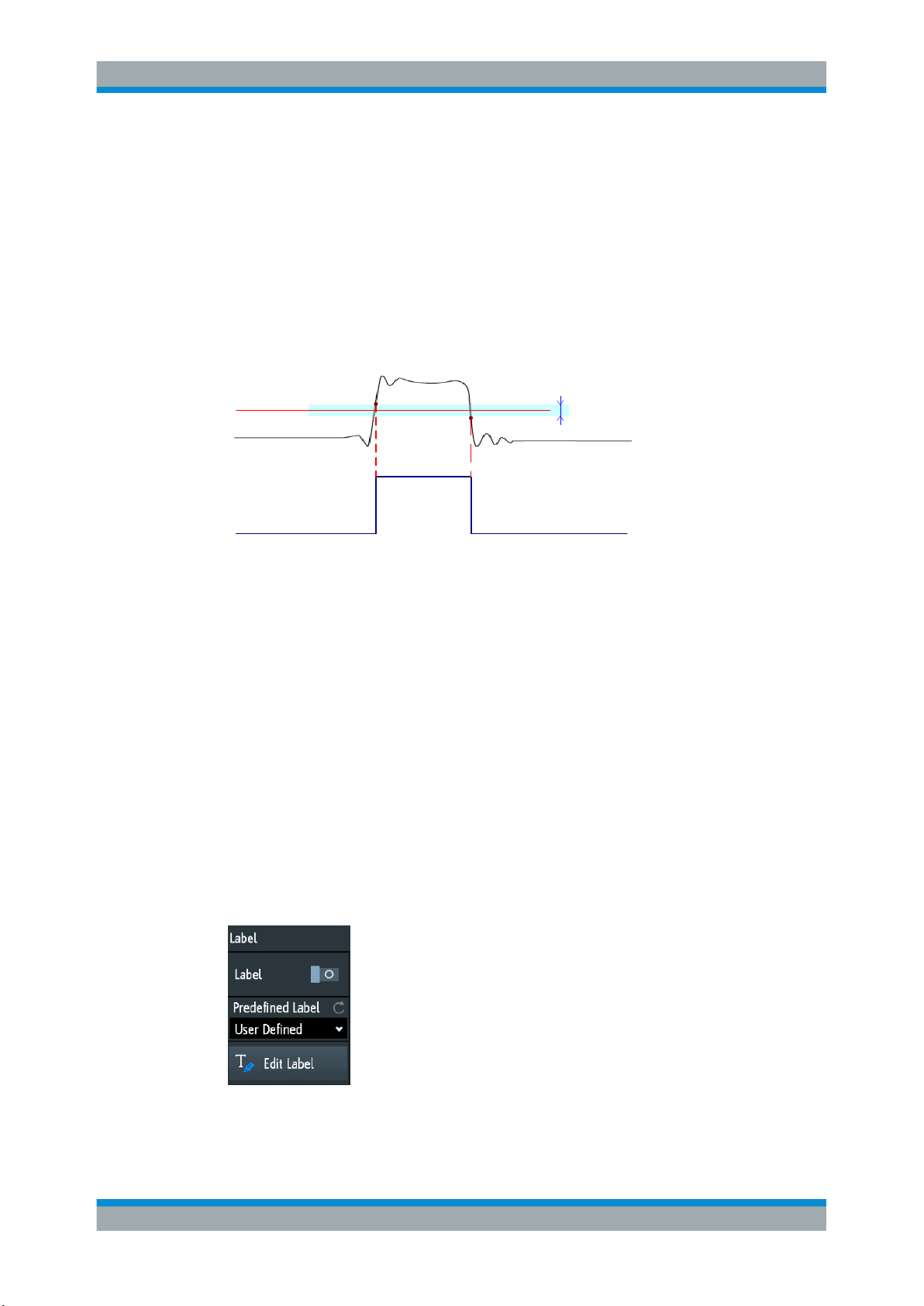
R&S®RTM3000
Waveform Setup
Vertical Setup
Threshold
A threshold is used for digitization of analog signals. If the signal value is higher than
the threshold, the signal state is high (1 or true for the Boolean logic). Otherwise, the
signal state is considered low (0 or false) if the signal value is below the threshold.
Remote command:
CHANnel<m>:THReshold on page 421
Hysteresis
To avoid the change of signal states due to noise, set the hysteresis. If the signal oscillates inside the hysteresis range and crosses the threshold, no state transition occurs.
Threshold
Logic 0 Logic 1 Logic 0
The numerical values of "Small", "Medium", and "Large" hysteresis correspond to the
vertical scale.
Remote command:
CHANnel<m>:THReshold:HYSTeresis on page 422
Find Threshold
The instrument analyzes the channel and sets the threshold for digitization. If no level
can be found, the existing value remains unchanged, and you can set the thresholds
manually.
Remote command:
CHANnel<m>:THReshold:FINDlevel on page 422
4.3.7 Label Settings
Hysteresis
In the "Label" menu, you can define a name label for the selected waveform.
Access: [Ch <n>] > "Label" (scroll down).
61User Manual 1335.9090.02 ─ 06

R&S®RTM3000
Waveform Setup
Horizontal Setup
Label
Activates or deactivates the label display. The label is shown at the waveform on the
right edge of the display.
Remote command:
CHANnel<m>:LABel:STATe on page 422
CHANnel<m>:LABel on page 422
Predefined Label
Selects a predefined label text. You can edit the text with "Edit Label".
Edit Label
Opens on-screen keypad to enter a label text. If you previously have selected a predefined label, it is already written in the entry line, and you can modify it.
The maximum name length is 8 characters, and only ASCII characters provided on the
on-screen keypad can be used.
4.4 Horizontal Setup
Horizontal settings, also known as timebase settings, adjust the waveforms in horizontal direction.
Typically, the trigger is the determining point of the waveform record. In many scenarios, you want to analyze the waveform some time before or after the trigger. To adjust
the horizontal acquisition window to the waveform section of interest, you can use the
following parameters:
●
The horizontal position defines the time distance of the trigger point (the zero
point of the diagram) to the reference point. Changing the horizontal position, you
can move the trigger point, even outside the screen.
●
The reference point is the rescaling center of the time scale on the screen. If you
modify the time scale, the reference point remains fixed on the screen, and the
scale is stretched or compressed to both sides of the reference point.
62User Manual 1335.9090.02 ─ 06
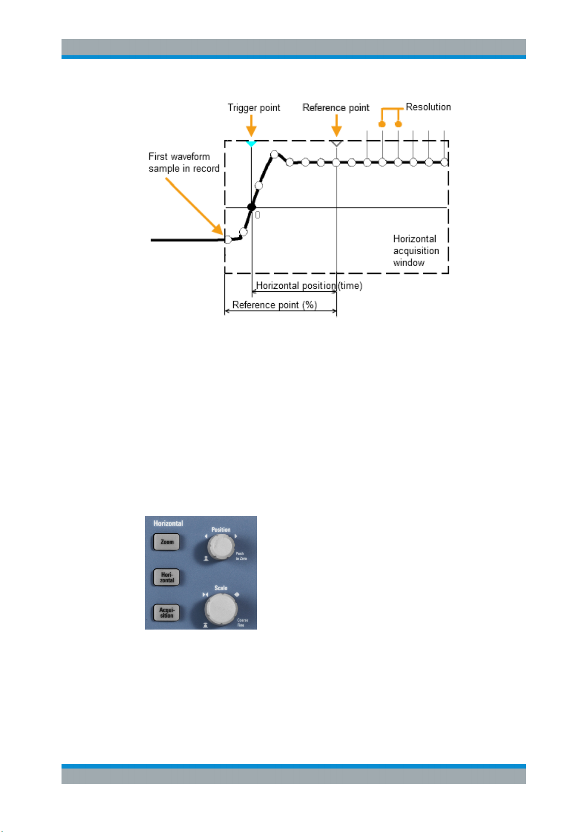
R&S®RTM3000
Waveform Setup
Horizontal Setup
Unlike vertical settings, which are waveform-specific, the horizontal settings apply to all
active waveforms.
There are several ways to adjust horizontal settings:
●
Use the controls in the Horizontal functional block of the front panel to scale the
waveforms, and to set the position.
●
Drag one finger horizontally on the screen to change the horizontal position.
Spread or pinch two fingers to change the horizontal scale.
●
Use shortcuts to adjust scale and position.
●
Use the comprehensive menu to adjust all horizontal settings.
4.4.1 HORIZONTAL Controls
[Position]
Changes the trigger position, the time distance from the trigger point to the reference
point (trigger offset). The trigger point is the zero point of the diagram. Thus, you can
set the trigger point even outside the diagram and analyze the signal some time before
or after the trigger.
63User Manual 1335.9090.02 ─ 06

R&S®RTM3000
Waveform Setup
Horizontal Setup
Turn clockwise to move the position to the right, and press the knob to reset the value
to zero. The current value is shown in the information bar.
In zoom and FFT, the knob sets the position in the active diagram. Tap the diagram
that you want to adjust. If a zoom is active, either the position of the zoom window or
the trigger position is changed. In an FFT diagram, the knob changes the center frequency in frequency domain, or the trigger position in time domain.
Remote command:
TIMebase:POSition on page 429
REFCurve<m>:HORizontal:POSition on page 459
TIMebase:ZOOM:TIME on page 451
[Scale]
Adjusts the time scale of the horizontal axis for all signals, also known as timebase.
Turn clockwise to stretch the waveforms - the scale value time/div decreases. Press
the knob to toggle between coarse and fine scale adjustment. The current value is
shown in the information bar.
In a zoom diagram, the knob changes the zoom scale. In an FFT diagram, the knob
changes the span. Tap the diagram that you want to adjust.
Remote command:
TIMebase:SCALe on page 429
REFCurve<m>:HORizontal:SCALe on page 459
TIMebase:ZOOM:SCALe on page 451
[Zoom]
Enables or disables the zoom with the last configuration.
See also: Chapter 6.1, "Zoom", on page 93.
Remote command:
TIMebase:ZOOM:STATe on page 451
[Horizontal]
Opens the menu to configure horizontal scale, position, and reference point. The current scale and position is shown in the top information bar.
If zoom is active, you can find also the zoom scale and zoom position in this menu.
[Acquisition]
Opens the "Acquisition" menu. Here you control the data processing - how the waveform is built from the captured samples. The current acquisition mode is shown in the
top information bar.
See also: Chapter 4.5, "Acquisition Setup", on page 66.
4.4.2 Shortcuts for Horizontal Settings
To adjust the horizontal scale and the position, you can use the shortcuts on the top of
the display. The labels show the current values.
64User Manual 1335.9090.02 ─ 06

R&S®RTM3000
4.4.3 Horizontal Settings
Waveform Setup
Horizontal Setup
1 = adjust horizontal scale
2 = adjust horizontal position
The comprehensive "Horizontal" menu contains all horizontal settings. In zoom mode,
also zoom settings are listed in the menu.
► To open the menu, press the [Horizontal] key.
Reference Point
Defines the time reference point in the diagram. It is indicated by a gray triangle outline
at the bottom of the diagram.
The reference point defines which part of the waveform is shown. By default, the reference point is displayed in the center of the window, and you can move it to the left or
right.
The reference point is the rescaling center of the time scale on the screen. If you modify the time scale using the [Scale] knob, the reference point remains fixed on the
screen, and the scale is stretched or compressed to both sides of the reference point.
If you spread and pinch two fingers on the touchscreen to change the time scale, then
the reference point is set between the fingers.
Remote command:
TIMebase:REFerence on page 430
Time Scale
Defines the time scale of the horizontal axis for all signals, also known as timebase.
The scaling is indicated in the information bar above the grid.
Remote command:
TIMebase:SCALe on page 429
65User Manual 1335.9090.02 ─ 06

R&S®RTM3000
4.5 Acquisition Setup
Waveform Setup
Acquisition Setup
Horizontal Position
Defines the trigger position, the time distance from the trigger point to the reference
point (trigger offset). The trigger point is the zero point of the diagram. Changing the
horizontal position, you can move the trigger, even outside the screen.
If you want to see a section of the waveform some time before or after the trigger, enter
this time as horizontal position. The requested waveform section is shown around the
reference point. Use positive values to see waveform sections after the trigger - the
waveform and the diagram origin move to the left.
The value is indicated in the information bar above the grid.
Remote command:
TIMebase:POSition on page 429
During an acquisition, the R&S RTM3000 captures the signal and converts it to digital
samples. The digital samples are processed according to the acquisition settings. The
result is a waveform record that is displayed on the screen and stored in memory.
The number of waveform samples in one waveform record is called the record length.
The rate of recording waveform samples - the number of waveform samples per second - is the sample rate. The higher the sample rate, the better is the resolution and
the more details of the waveform are visible.
A sufficient resolution is essential for correct reconstruction of the waveform. If the signal is undersampled, aliasing occurs - a false waveform is displayed. To avoid aliasing
and accurately reconstruct a signal, the sample rate must be at least 3 to 5 times the
fastest frequency component of the signal.
There are several ways to adjust and control acquisition:
●
Use the controls in the Trigger functional block of the front panel to start and stop
acquisition. See Chapter 5.1, "Trigger Controls", on page 72.
●
Use shortcuts to adjust the acquisition mode, and to perform a single acquisition.
●
Use the comprehensive menu to adjust all acquisition settings.
► To start or stop acquisition, use the [Run Stop] and [Single] keys in the Trigger sec-
tion at the front panel.
4.5.1 Shortcuts for Acquisition Settings
To adjust the acquisition mode, and to perform a single acquisition, you can use the
shortcuts on the top of the display. The labels show the current values.
66User Manual 1335.9090.02 ─ 06

R&S®RTM3000
4.5.2 Acquisition Settings
Waveform Setup
Acquisition Setup
1 = start or stop a continuous acquisition, or start a single acquisition if [Single] is active
2 = adjust the acquisition mode
3 = shows the current sample rate for information
Acquisition settings define the processing of the captured samples in the instrument.
The current acquisition mode and sample rate are shown in the top information bar.
► To adjust acquisition settings, press the [Acquisition] key.
The history is described in Chapter 6.4.3, "History Settings", on page 114.
Record Length
Sets the record length, the number of waveform samples that are stored in one waveform record.
If you use the history, you can disable the "Auto" record length and enter a value in the
"History" menu. In this case, the defined record length is shown in the "Acquisition"
menu.
Remote command:
ACQuire:POINts:AUTomatic on page 431
ACQuire:POINts[:VALue] on page 431
67User Manual 1335.9090.02 ─ 06

R&S®RTM3000
Waveform Setup
Acquisition Setup
Acquire Mode
Defines how the waveform is built from the captured samples. There are two general
methods to build the waveform record: sample decimation and waveform arithmetic.
Sample decimation reduces the data stream of the ADC to a stream of waveform
points with lower sample rate and a less precise time resolution. The R&S RTM3000
uses decimation, if the waveform sample rate is less than the ADC sample rate. The
acquisition modes "Peak Detect" and "High Resolution" are decimation methods.
Waveform arithmetic builds the resulting waveform from several consecutive acquisitions of the signal. The acquisition modes "Average" and "Envelope" are arithmetic
methods.
"Sample"
"Peak Detect"
"High Resolution"
"Average"
"Average +
HR"
"Envelope"
"Envelope + PD"
"Envelope +
HR"
Usually, most signals are displayed optimally with this acquisition
mode but very short glitches might remain undiscovered by this
method.
If the sample rate of the waveform is less than the ADC sample rate,
the instrument reduces the number of samples: one of n samples in a
sample interval is recorded as waveform point, the other samples are
discarded (decimation). Conversely, if the sample rate of the waveform is higher than the ADC sample rate, the instrument adds waveform points to the captured samples using an interpolation method.
The minimum and the maximum of n samples are recorded as waveform points, the other samples are discarded. Thus the instrument
can detect fast signal peaks at slow time scale settings that would be
missed with other acquisition modes.
The average of n captured sample points is recorded as one waveform sample. Averaging reduces the noise, the result is a more precise waveform with higher vertical resolution.
The average is calculated from the data of the current acquisition and
a number of consecutive acquisitions before. The method reduces
random noise. It requires a stable, triggered and repetitive signal.
The number of acquisitions for average calculation is defined with
"No. of Averages" on page 69.
Combines the high resolution mode with averaging over several
acquisitions.
Each acquisition is done in sample mode, and the minimum and maximum values over some consecutive acquisitions build the envelope.
The resulting diagram shows two envelope waveforms below and
above the normal waveform: the minimums (floor) and maximums
(roof), representing the borders in which the signal occurs. this
method is useful, for example, if the waveform is noisy but the noise
is not relevant for the measurement.
Each acquisition is done in peak detect mode, and the most extreme
values of all consecutive acquisitions build the envelope. This method
is more precise than "Envelope".
Each acquisition is done in high resolution mode, and the minimum
and maximum values over some consecutive acquisitions build the
envelope.
68User Manual 1335.9090.02 ─ 06

R&S®RTM3000
Waveform Setup
Acquisition Setup
Remote command:
CHANnel<m>:ARIThmetics on page 432
CHANnel<m>:TYPE on page 432
ACQuire:PEAKdetect on page 433
ACQuire:HRESolution on page 433
No. of Averages
Defines the number of waveforms used to calculate the average waveform. The higher
the number, the better the noise is reduced.
To restart the average calculation, press the [Clear Screen] key.
Remote command:
ACQuire:AVERage:COUNt on page 433
ACQuire:AVERage:RESet on page 433
Nx Single
Sets the number of waveforms that are acquired with a [Single] acquisition.
The setting is available if the history option is installed.
Remote command:
ACQuire:NSINgle:COUNt on page 415
Roll
Enables the automatic roll mode. The instrument switches to roll mode if the Time
Scale is equal or slower than Start Roll Time.
The roll mode displays the untriggered, continuous signal, and moves the captured
input data on the display from the left to the right. The instrument shows the waveform
immediately, without waiting for the complete acquisition of the waveform record. The
record length is set automatically ("Auto" mode). Some math functions are non-calculable if roll mode is active.
You can use the horizontal and vertical zoom in roll mode if the acquisition is stopped.
Remote command:
TIMebase:ROLL:AUTomatic on page 434
Start Roll Time
Sets the limit timebase for the roll mode. The instrument switches automatically to roll
mode if:
●
the Time Scale exceeds the value given here.
●
the roll mode is activated (Roll).
Remote command:
TIMebase:ROLL:MTIMe on page 434
Interpolation
Selects the interpolation method if interpolation is required to get the defined record
length.
69User Manual 1335.9090.02 ─ 06

R&S®RTM3000
Waveform Setup
Acquisition Setup
"Sin(x)/x"
"Linear"
"Sample-Hold"
Remote command:
ACQuire:INTerpolate on page 434
Two adjacent ADC sample points are connected by a sin(x)/x curve,
and also the adjoining sample points are considered by this curve.
The interpolated points are placed on the resulting curve. This interpolation method is the default method. It is precise and shows the
best signal curve.
Two adjacent ADC sample points are connected by a straight line, the
interpolated points are placed on the line. You see a polygonal waveform similar to the real signal, and also the ADC sample points as
vertexes.
The ADC sample points are displayed like a histogram. For each
sample interval, the voltage is taken from the sample point and considered as constant, and the intervals are connected with vertical
lines. Thus, you see the discrete values of the ADC.
70User Manual 1335.9090.02 ─ 06

R&S®RTM3000
5 Trigger
Trigger
Triggering means to capture the interesting part of the relevant waveforms. Choosing
the right trigger type and configuring all trigger settings correctly allows you to detect
various incidents in signals.
A trigger occurs if the trigger conditions are fulfilled. The instrument acquires continuously and keeps the sample points to fill the pretrigger part of the waveform record.
When the trigger occurs, the instrument continues acquisition until the posttrigger part
of the waveform record is filled. Then it stops acquiring and displays the waveform.
When a trigger is recognized, the instrument does not accept another trigger until the
acquisition is complete.
Trigger conditions include:
●
Source of the trigger signal (channel)
●
Trigger type and its setup
●
Trigger mode
In addition, the horizontal position of the trigger point and the reference point are
important to display the interesting part of the signal. See Chapter 4.4, "Horizontal
Setup", on page 62.
The trigger level and position are marked in the grid. The markers have the color of the
trigger source. Information on the most important trigger settings is shown in the upper
information bar.
There are several ways to set up the trigger:
●
Use the controls in the Trigger functional block of the front panel.
●
Use shortcuts to adjust the trigger source, trigger mode, and main parameters of
the trigger type.
●
Use the comprehensive menu to select the trigger type and to adjust all trigger settings.
The R&S RTM3000 can output a pulse at the Aux Out connector when the instrument
triggers. See
● Trigger Controls...................................................................................................... 72
● Shortcuts for Trigger Settings................................................................................. 73
● General Trigger Settings.........................................................................................74
● Edge Trigger........................................................................................................... 76
● Edge A/B Trigger.....................................................................................................78
● Width Trigger...........................................................................................................79
● Video Trigger...........................................................................................................82
● Pattern Trigger........................................................................................................ 84
● Runt Trigger............................................................................................................ 87
● Rise Time Trigger....................................................................................................88
● Timeout Trigger.......................................................................................................90
● Trigger Out Signal...................................................................................................92
71User Manual 1335.9090.02 ─ 06

R&S®RTM3000
5.1 Trigger Controls
Trigger
Trigger Controls
The keys and the rotary knob in the Trigger functional block adjust the trigger and start
or stop acquisition.
The green LED above the [Levels] knob lights up when the instrument triggers.
[Trigger]
Opens the "Trigger" menu.
[Source]
Changes the analog trigger source. Press the key repeatedly until the required analog
source is selected. If a digital source or serial bus was selected in the "Trigger" menu,
or if the "Trigger Type" is set to "Pattern", the key opens the menu.
The key lights up in the color of the selected channel, and the selected source is
shown in the information bar.
Remote command:
TRIGger:A:SOURce on page 436
[Auto Norm]
Toggles the trigger mode between "Auto" and "Norm". The key lights up in white if the
trigger mode is "Norm". The current mode is also shown in the information bar.
"Auto"
"Norm"
Remote command:
TRIGger:A:MODE on page 436
[Levels]
The rotary knob changes the trigger level. Turn clockwise to move up the trigger level.
Pressing the knob sets the level to 50% of the signal amplitude.
The instrument triggers repeatedly after a time interval if the trigger
conditions are not fulfilled. If a real trigger occurs, it takes precedence. This mode helps to see the waveform even before the trigger
is set. The waveform on the screen is not synchronized, and successive waveforms are not triggered at the same point of the waveform.
The instrument acquires a waveform only if a trigger occurs, that is, if
all trigger conditions are fulfilled. If no trigger occurs, no waveform is
acquired and the last acquired waveform is displayed. If no waveform
was captured before, nothing is displayed.
72User Manual 1335.9090.02 ─ 06

R&S®RTM3000
Trigger
Shortcuts for Trigger Settings
Remote command:
TRIGger:A:LEVel<n>[:VALue] on page 438
TRIGger:A:FINDlevel on page 438
[Force Trigger]
Provokes an immediate single acquisition. Use this key if the acquisition is running in
normal mode and no valid trigger occurs. Thus, you can confirm that a signal is available and use the waveform display to determine how to trigger on it.
Remote command:
*TRG on page 414
[Run Stop]
Starts and stops the continuous acquisition. A green light indicates a running acquisition. A red light shows that acquisition is stopped.
The status is shown also at the right end of the information bar: "Run", "Complete",
"Trig?" (waiting for trigger, in normal trigger mode) or "Not ready" (working). For slow
timebases, the status "Pre" or "Post" is shown together with an indicator that shows the
filling level of the buffer.
Remote command:
RUN on page 415
RUNContinous on page 415
STOP on page 416
ACQuire:STATe on page 416
[Single]
Starts a specified number of acquisitions. A white light indicates that the instrument is
in single mode. The information bar shows "Complete" if the acquisition has been finished.
If the history option R&S RTM3000-K15 is available, you can set the number of acquisitions: press the [Acquisition] key and enter "Nx Single".
Remote command:
SINGle on page 415
RUNSingle on page 415
5.2 Shortcuts for Trigger Settings
To adjust the trigger source, mode, and trigger type specific settings, you can use the
shortcuts on the top of the display. The labels show the current values.
73User Manual 1335.9090.02 ─ 06

R&S®RTM3000
5.3 General Trigger Settings
Trigger
General Trigger Settings
1 = adjust the trigger source
2 = open the keypad to enter the value of the trigger level or threshold
3 = adjust slope or polarity
4 = adjust the trigger mode
5 = start or stop a continuous acquisition, or start a single acquisition if [Single] is active
6 = available settings depend on the trigger type
General trigger settings are independent of the trigger type. They are highlighted in the
above figure and described in the current section. The other trigger settings are specific for individual trigger types, and they are described in the following sections.
Trigger Mode
Toggles the trigger mode between "Auto" and "Norm". The trigger mode determines the
behavior of the instrument if no trigger occurs. The current setting is shown in the information bar.
74User Manual 1335.9090.02 ─ 06

R&S®RTM3000
Trigger
General Trigger Settings
"Auto"
"Norm"
Remote command:
TRIGger:A:MODE on page 436
Trigger Type
Selects the trigger type.
"Edge"
"Edge A/B"
"Width"
"Video"
"Pattern"
"Runt"
"Risetime"
"Timeout"
"Line"
"Serial Bus"
Remote command:
TRIGger:A:TYPE on page 437
The instrument triggers repeatedly after a time interval if the trigger
conditions are not fulfilled. If a real trigger occurs, it takes precedence. This mode helps to see the waveform even before the trigger
is set. The waveform on the screen is not synchronized, and successive waveforms are not triggered at the same point of the waveform.
The instrument acquires a normal waveform only, if a trigger occurs,
that is, if all trigger conditions are fulfilled. If no trigger occurs, no
waveform is acquired and the last acquired waveform is displayed. If
no waveform was captured before, nothing is displayed.
Triggers on signal edges.
See Chapter 5.4, "Edge Trigger", on page 76.
Triggers on a sequence of two edge trigger conditions.
See Chapter 5.5, "Edge A/B Trigger", on page 78
Triggers on pulse width.
See Chapter 5.6, "Width Trigger", on page 79.
Triggers on various PAL, NTSC and HDTV standard video signals.
See Chapter 5.7, "Video Trigger", on page 82.
Triggers on logical combinations of the input channels.
See Chapter 5.8, "Pattern Trigger", on page 84.
Triggers on pulses lower than normal in amplitude.
See Chapter 5.9, "Runt Trigger", on page 87.
Triggers on fast or slow rising or falling edges.
See Chapter 5.10, "Rise Time Trigger", on page 88.
Triggers on signal level timeout.
See Chapter 5.11, "Timeout Trigger", on page 90.
The line trigger uses the waveform of the power supply's alternating
line voltage (typically 50 Hz or 60 Hz AC) as the trigger signal source.
Use this trigger to detect issues related to the frequency of the power
grid.
The line trigger does not have any settings.
Triggers on a serial bus. Requires that at least one protocol option
R&S RTM-K1, -K2, or -K3 is installed, a serial bus is configured, and
a decoded signal is available.
See Chapter 12.1.1, "Protocol - Common Settings", on page 231.
Source
Selects the trigger source.
75User Manual 1335.9090.02 ─ 06

R&S®RTM3000
Trigger
Edge Trigger
"C1, C2, C3,
C4"
"D0 to D15"
"Extern"
"B1, B2, B3 or
B4"
Remote command:
TRIGger:A:SOURce on page 436
Hold Off, Hold Off Time
Enables the hold off and defines the "Hold Off Time". The next trigger occurs only after
the hold off time has passed.
The trigger "Hold Off" defines when the next trigger event is recognized after the current trigger event. Thus, it affects the next trigger to occur after the current one. Hold
off helps to obtain stable triggering when the oscilloscope is triggering on undesired
events.
Remote command:
TRIGger:A:HOLDoff:MODE on page 437
TRIGger:A:HOLDoff:TIME on page 438
Select one of the analog input channels as trigger source.
Select one of the digital channels as trigger source if MSO option
R&S RTM-B1 is installed.
Not available for video, runt, and risetime trigger.
Sets the external trigger input on the front panel as trigger source.
Available for edge and video trigger.
Serial bus that is used for triggering on protocols. Only available, if
the trigger type "Serial Bus" is selected.
5.4 Edge Trigger
The edge trigger is the most common trigger type. The trigger occurs when the signal
from the trigger source passes the trigger level in the specified direction (slope).
Figure 5-1: Edge trigger event with positive slope (rising edge)
► [Trigger] > "Trigger Type" = "Edge"
76User Manual 1335.9090.02 ─ 06

R&S®RTM3000
Trigger
Edge Trigger
Slope.............................................................................................................................77
Trigger Level, Threshold............................................................................................... 77
Hysteresis..................................................................................................................... 78
Coupling........................................................................................................................78
HF Reject...................................................................................................................... 78
Noise Reject..................................................................................................................78
Slope
Sets the edge direction for the trigger. You can trigger on:
●
●
●
Remote command:
TRIGger:A:EDGE:SLOPe on page 438
Trigger Level, Threshold
Sets the voltage level or threshold for the trigger.
You can also drag the trigger level marker on the display, or turn the Levels knob. To
set the trigger level to 50% of the signal amplitude, press the Levels knob.
For width and timeout trigger, the trigger level is the threshold of the trigger source.
Remote command:
TRIGger:A:LEVel<n>[:VALue] on page 438
TRIGger:A:FINDlevel on page 438
rising edge, that is a positive voltage change
falling edge, that is a negative voltage change
rising and falling edge. After starting an acquisition, the instrument triggers on
the first identified edge.
77User Manual 1335.9090.02 ─ 06

R&S®RTM3000
Trigger
Edge A/B Trigger
Hysteresis
Sets a hysteresis range around the trigger level. Hysteresis avoids unwanted trigger
events caused by noise oscillation around the trigger level. The automatic, small,
medium, large hysteresis values depend on the vertical scale. On instruments with
1 GHz bandwidth, you can also set the hysteresis to user-defined values.
Remote command:
TRIGger:A:HYSTeresis on page 439
TRIGger:A:LEVel<n>:HYSTeresis on page 439
Coupling
Sets the coupling for the trigger source.
"AC"
"DC"
"LF Reject"
Remote command:
TRIGger:A:EDGE:COUPling on page 439
Alternating current coupling. A highpass filter removes the DC offset
voltage from the trigger signal.
Direct current coupling. The trigger signal remains unchanged.
Sets the trigger coupling to high frequency. A 15 kHz highpass filter
removes lower frequencies from the trigger signal. Use this mode
only with very high frequency signals.
HF Reject
Enables or disables an additional 5 kHz lowpass filter in the trigger path. This filter
removes higher frequencies and is available with AC and DC coupling.
You can use either "HF Reject" or "Noise Reject".
Remote command:
TRIGger:A:EDGE:FILTer:HFReject on page 439
Noise Reject
Extends the hysteresis to avoid unwanted trigger events caused by noise oscillation
around the trigger level.
You can use either "HF Reject" or "Noise Reject".
Remote command:
TRIGger:A:EDGE:FILTer:NREJect on page 440
5.5 Edge A/B Trigger
The edge A/B trigger is a sequence of two edge trigger conditions. The instrument triggers if both edge trigger conditions (A and B) are fulfilled. You can configure a delay
between the A- and B-trigger.
► [Trigger] > "Trigger Type" = "Edge A/B" > "Trigger Setup"
78User Manual 1335.9090.02 ─ 06

R&S®RTM3000
Trigger
Width Trigger
Trigger Setup
Opens a dialog where you configure the trigger sequence. On the left, the first edge
trigger (A) is defined as usual. On the right, a second edge trigger (B) is defined with
the same parameters: source, level, edge, and hysteresis. The conditions of the B-trigger are considered when the conditions of the A-trigger are met.
In addition, you can set a delay for the B-trigger ("Trigger").
Remote command:
TRIGger:B:ENABle on page 440
TRIGger:B:SOURce on page 440
TRIGger:B:EDGE:SLOPe on page 441
Trigger
Sets a time delay or event delay for the B-trigger. The instrument waits for that delay
after an A-trigger until it recognizes the B-trigger.
"After time"
"After events"
Remote command:
TRIGger:B:MODE on page 441
TRIGger:B:DELay on page 441
TRIGger:B:EVENt:COUNt on page 441
Sets the time the instrument waits until it checks the B-trigger condition.
Sets a number of B-trigger events that fulfill the B-trigger condition
but do not cause the trigger. The oscilloscope triggers on the n-th
event, the last of the specified number of events.
5.6 Width Trigger
The width trigger compares the pulse width (duration) with given time limits. It detects
pulses with an exact pulse width, pulses shorter or longer than a given time, and also
pulses inside or outside the allowable time range. The pulse width is measured at the
trigger level.
79User Manual 1335.9090.02 ─ 06

R&S®RTM3000
Trigger
Width Trigger
You can use the width trigger, for example, to trigger on glitches.
Figure 5-2: Pulse width is shorter (left) or longer (right) than a given duration (also known as glitch
Figure 5-3: Pulse width is inside or outside an allowable time range
1 = Inside: min width < pulse < max width
2 = Outside: pulse < min width OR pulse > max width
min
max
±Δ
trigger)
min
1 2
max
±Δ
1 2
Figure 5-4: Pulse width is equal or unequal to a given duration, with optional variation (Δ)
1 = Equal: (width - variation) < pulse < (width + variation)
2 = Unequal: pulse < (width - variation) OR pulse > (width + variation)
► [Trigger] > "Trigger Type" = "Width"
80User Manual 1335.9090.02 ─ 06

R&S®RTM3000
Trigger
Width Trigger
Polarity.......................................................................................................................... 81
Comparison...................................................................................................................81
Time t............................................................................................................................ 82
Variation........................................................................................................................ 82
Time t1, Time t2.............................................................................................................82
Threshold...................................................................................................................... 82
Hysteresis..................................................................................................................... 82
Polarity
Sets the polarity of the pulse. You can trigger on:
●
●
Remote command:
TRIGger:A:WIDTh:POLarity on page 442
Comparison
Sets how the measured pulse width is compared with the given limits.
"Width >"
"Width <"
"Width ="
positive going pulse, the width is defined from the rising to the falling slopes.
negative going pulse, the width is defined from the falling to the rising slopes.
Triggers on pulse width longer than the reference "Time t".
Triggers on pulse width shorter than the reference "Time t".
Triggers on pulse width equal to the reference "Time t" if "Variation"
Δt = 0.
If "Variation" ≠ 0, this setting triggers on pulses within the range t±Δt.
"Width ≠"
Triggers on pulses unequal to the reference "Time t", if "Variation"
Δt = 0.
If "Variation" ≠ 0, this setting triggers on pulses outside a range t
± Δ
81User Manual 1335.9090.02 ─ 06
t.

R&S®RTM3000
Trigger
Video Trigger
"Inside"[, ]"Outside"
Remote command:
TRIGger:A:WIDTh:RANGe on page 442
Time t
Sets the reference time, the nominal value for comparison settings "Width >",
"Width <", "Width =", and "Width ≠".
Remote command:
TRIGger:A:WIDTh:WIDTh on page 442
Variation
Sets a range Δt to the reference "Time t", if comparison is set to "Width =" or "Width ≠".
The instrument triggers on pulses inside or outside the range t±Δt.
Remote command:
TRIGger:A:WIDTh:DELTa on page 443
Time t1, Time t2
Set the lower and upper time limits defining the time range if "Width =" or "Width ≠" is
set for comparison. "Time t" and "Variation" are adjusted accordingly.
Remote command:
TRIGger:A:WIDTh:RANGe on page 442
TRIGger:A:WIDTh:DELTa on page 443
Triggers on pulses inside or outside a range specified with "Time t1"
and "Time t2".
This method is an alternative setting to the range definition with
"Time t" and "Variation". The values are interdependent. "Variation"
and "Time t" are adjusted, if you change t1 and t2, and vice versa.
Threshold
Threshold of the trigger source channel, used as trigger level for the width trigger.
See also "Threshold" on page 61 and "Trigger Level, Threshold" on page 77.
Remote command:
TRIGger:A:LEVel<n>[:VALue] on page 438
CHANnel<m>:THReshold on page 421
Hysteresis
Hysteresis of the trigger source channel, see "Hysteresis" on page 61.
Remote command:
CHANnel<m>:THReshold:HYSTeresis on page 422
5.7 Video Trigger
The video or TV trigger is used to analyze analog baseband video signals. You can
trigger on baseband video signals from standard definition and high definition standards connected to an analog channel input or to the external trigger input.
The instrument triggers on the sync pulses.
82User Manual 1335.9090.02 ─ 06

R&S®RTM3000
Trigger
Video Trigger
First select the standard and the signal polarity, then decide to trigger on lines or fields
and enter the specific settings.
► [Trigger] > "Trigger Type" = "Video"
Figure 5-5: Video trigger menu
Standard........................................................................................................................83
Signal............................................................................................................................ 84
Mode............................................................................................................................. 84
Line............................................................................................................................... 84
Standard
Selects the color television standard.
You can trigger on various standard-definition television (SDTV) signals:
●
"PAL"
●
"NTSC"
●
"SECAM"
●
"PAL-M"
●
"SDTV 576i" (PAL and SECAM)
High-definition television (HDTV) standards are indicated by the number of active lines
and the scanning system:
●
"HDTV 720p"
●
"HDTV 1080p" (p for progressive scanning)
●
"HDTV 1080i" (i for interlaced scanning)
Remote command:
TRIGger:A:TV:STANdard on page 443
83User Manual 1335.9090.02 ─ 06

R&S®RTM3000
T
T
Trigger
Pattern Trigger
Signal
Selects the polarity of the signal. Note that the sync pulse has the opposite polarity. If
the video modulation is positive, the sync pulses are negative. If the modulation is negative, sync pulses are positive. The edges of the sync pulses are used for triggering,
therefore incorrect polarity setting causes a sporadic triggering by the video information.
Figure 5-6: Positive video signal with negative bi-level sync pulse (SDTV, left) and negative signal
with positive tri-level sync pulse (HDTV, right)
Remote command:
TRIGger:A:TV:POLarity on page 443
Mode
Selects from the following the trigger conditions:
"All Frames"
"Odd Frames"
The oscilloscope triggers on the beginning of all video signal frames.
The oscilloscope triggers on the beginning of video signal frames with
an odd frame number.
"Even Frames"
The oscilloscope triggers on the beginning of video signal frames with
an even frame number.
"All Lines"
"Line Number"
The oscilloscope triggers on the beginning of all video signal lines.
Triggers on an exact "Line" number.
Remote command:
TRIGger:A:TV:FIELd on page 444
Line
Sets an exact line number if "Mode" is "Line Number". The oscilloscope triggers exactly
on the beginning of the selected line in any field.
Remote command:
TRIGger:A:TV:LINE on page 444
5.8 Pattern Trigger
The pattern trigger is a logic trigger. It provides any logical combination of the input
channels and supports you in verifying the operation of digital logic. Additionally, you
can set a time limitation to the pattern. Thus you can also trigger on bus patterns of
parallel buses.
The channel pattern is configured in the "Logic Editor" dialog box.
84User Manual 1335.9090.02 ─ 06

R&S®RTM3000
Trigger
Pattern Trigger
► [Trigger] > "Trigger Type" = "Pattern" > "Edit Pattern"
Figure 5-7: Pattern trigger with logic editor
Thresholds
At the bottom of the "Logic Editor", you see the current threshold settings of all channels. Here, you can directly activate the channels, and change the threshold values.
The thresholds of analog channels are also set in the "Channel <n>" > "Threshold"
menu, see also Chapter 4.3.6, "Threshold Settings", on page 60.
The thresholds of logic channels are also set in the [Logic] > "Threshold and Deskew"
dialog, see Chapter 14.2, "Logic Analyzer Settings", on page 374.
Logic settings
H | L | X, Set All.............................................................................................................85
And | Or.........................................................................................................................86
Duration.........................................................................................................................86
True | False................................................................................................................... 86
Time limitation...............................................................................................................86
H | L | X, Set All
Defines the pattern by selecting the state "H" (high), "L" (low) or "X" (do not care) for
each active analog and digital channel.
The word length of the pattern depends on the number of available analog and digital
channels.
Analog channels: 2 bit for 2-channel instruments, 4 bit for 4-channel instruments.
Digital (16 bit): the logic channels D0, D1,...,D15 are only available with MSO option
R&S RTM-B1.
Thus the pattern can have 2, 4, 18, or 20 bits.
Use "Set All" to set all channels to the same state.
85User Manual 1335.9090.02 ─ 06

R&S®RTM3000
Trigger
Pattern Trigger
Remote command:
TRIGger:A:PATTern:SOURce on page 445
And | Or
Sets the logical combination of the channel states.
"AND"
"OR"
Remote command:
TRIGger:A:PATTern:FUNCtion on page 445
Duration
The switch has the following two effects:
●
Selects the mode of the True | False comparison.
●
Enables or disables the Time limitation.
True | False
Defines whether the instrument triggers on fulfillment of the logical condition, or on violation.
●
If Duration = on, the instrument triggers when the logic combination "Is True" or
"Is False" for a specified time duration.
●
If Duration = off, the instrument triggers when the logic combination is found in the
signal ("Goes True"), or if it disappears ("Goes False").
All defined states must be true.
At least one of the defined states must be true.
Remote command:
TRIGger:A:PATTern:CONDition on page 445
Time limitation
To set a time limitation for the pattern, you have several possibilities. They are similar
to the setting of a pulse width, see Chapter 5.6, "Width Trigger", on page 79.
●
"Timeout" and "Time t"
Define a minimum time during which the signals match the pattern condition.
●
"Width >" or "Width <" and "Time t"
Triggers if the pattern condition changes before or after the specified time.
●
"Width =", "Time t1" and "Variation"
Triggers if the pattern condition is fulfilled for a duration "Time t1" ± "Variation".
●
"Width ≠", "Time t1" and "Variation"
Triggers if the pattern condition is fulfilled for a duration shorter than "Time t1" "Variation", or longer than "Time t1" + "Variation".
●
"Inside", "Time t1" and "Time t2"
Triggers if the pattern condition is fulfilled for a duration between "Time t1" and
"Time t2". These settings are an alternative setting to the definition with "Width =".
The time values are interdependent and adjusted accordingly.
●
"Outside", "Time t1" and "Time t2"
Triggers if the pattern condition is fulfilled for a duration shorter than "Time t1", or
longer than "Time t2". These settings are an alternative setting to the definition with
"Width ≠". The time values are interdependent and adjusted accordingly.
86User Manual 1335.9090.02 ─ 06

R&S®RTM3000
5.9 Runt Trigger
Trigger
Runt Trigger
Remote command:
TRIGger:A:PATTern:MODE on page 446
TRIGger:A:PATTern:WIDTh:RANGe on page 446
TRIGger:A:PATTern:WIDTh[:WIDTh] on page 446
TRIGger:A:PATTern:WIDTh:DELTa on page 447
A runt is a pulse lower than normal in amplitude. The amplitude crosses the first
threshold twice in succession without crossing the second one. For example, this trigger can detect logic, digital, and analog signals remaining below a specified threshold
amplitude because I/O ports are in undefined state.
► [Trigger] > "Trigger Type" = "Runt"
Polarity.......................................................................................................................... 87
Upper Level...................................................................................................................88
Lower Level...................................................................................................................88
Hysteresis..................................................................................................................... 88
Find Threshold.............................................................................................................. 88
Polarity
Sets the polarity of a pulse, that is the direction of the first pulse slope.
●
●
●
Remote command:
TRIGger:A:RUNT:POLarity on page 448
positive going pulse, the width is defined from the rising to the falling slopes.
negative going pulse, the width is defined from the falling to the rising slopes.
selects both positive and negative going pulses.
87User Manual 1335.9090.02 ─ 06

R&S®RTM3000
Trigger
Rise Time Trigger
Upper Level
Sets the upper voltage threshold for runt detection. A negative runt crosses the upper
level twice without crossing the lower level.
Remote command:
TRIGger:A:LEVel<n>:RUNT:UPPer on page 447
Lower Level
Sets the lower voltage threshold for runt detection. A positive runt crosses the lower
level twice without crossing the upper level.
Remote command:
TRIGger:A:LEVel<n>:RUNT:LOWer on page 447
Hysteresis
Hysteresis of the trigger source channel, see "Hysteresis" on page 61.
Remote command:
CHANnel<m>:THReshold:HYSTeresis on page 422
Find Threshold
The instrument analyzes the signal and sets the upper and lower trigger levels. If no
level can be found, the existing values remain unchanged, and you can set the thresholds manually.
5.10 Rise Time Trigger
The rise time trigger, also known as slew rate or transition trigger, can detect fast or
slow rising or falling edges selectively. It triggers on edges, if the rise or fall time from
the lower to higher voltage level (or vice versa) is shorter or longer as defined, or inside
or outside a specified time range. The trigger finds slew rates that are faster than
expected or permissible to avoid overshooting and other interfering effects. It also
detects very slow edges violating the timing in pulse series.
► [Trigger] > "Trigger Type" = "Risetime"
88User Manual 1335.9090.02 ─ 06
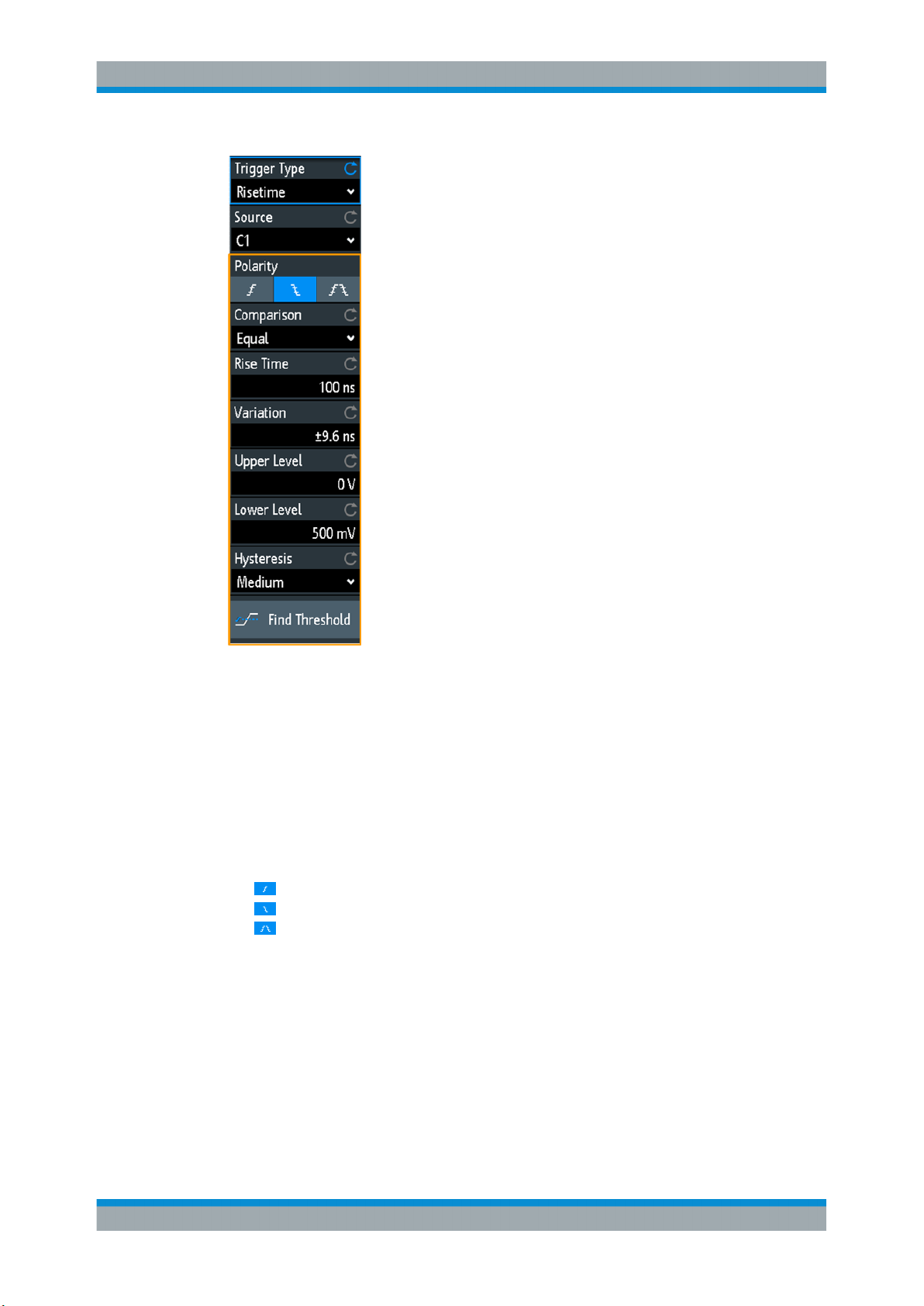
R&S®RTM3000
Trigger
Rise Time Trigger
Polarity.......................................................................................................................... 89
Comparison...................................................................................................................89
Rise Time......................................................................................................................90
Variation........................................................................................................................ 90
Upper Level...................................................................................................................90
Lower Level...................................................................................................................90
Hysteresis..................................................................................................................... 90
Find Threshold.............................................................................................................. 90
Polarity
Sets the edge, the transition time of which is to be analyzed:
●
●
●
Remote command:
TRIGger:A:RISetime:SLOPe on page 449
Comparison
Selects how the time limit for the slew rate is defined. The time measurement starts
when the signal crosses the first trigger level - the upper or lower level depending on
the selected slope - and stops when the signal crosses the second level.
"Greater than"
"Lower than"
rise time trigger
fall time trigger
rise and fall time trigger
Triggers on transition times longer than the given "Rise Time".
Triggers on transition times shorter than the given "Rise Time".
89User Manual 1335.9090.02 ─ 06

R&S®RTM3000
Trigger
Timeout Trigger
"Equal"
"Not equal"
Remote command:
TRIGger:A:RISetime:RANGe on page 449
Rise Time
Sets the reference rise time, the nominal value for comparisons.
Remote command:
TRIGger:A:RISetime:TIME on page 450
Variation
Defines a time range around the given "Rise Time" value.
Remote command:
TRIGger:A:RUNT:DELTa on page 447
Upper Level
Sets the upper voltage threshold. When the signal crosses this level, the slew rate
measurement starts or stops depending on the selected polarity.
Remote command:
TRIGger:A:LEVel<n>:RISetime:UPPer on page 449
Triggers on transition times inside the time range Rise Time ± Varia-
tion.
Triggers on transition times outside the time range Rise Time ± Varia-
tion.
Lower Level
Sets the lower voltage threshold. When the signal crosses this level, the slew rate
measurement starts or stops depending on the selected slope.
The value corresponds to the threshold value of the trigger channel.
Remote command:
TRIGger:A:LEVel<n>:RISetime:LOWer on page 448
Hysteresis
Hysteresis of the trigger source channel, see "Hysteresis" on page 61.
Remote command:
CHANnel<m>:THReshold:HYSTeresis on page 422
Find Threshold
See "Find Threshold" on page 88.
5.11 Timeout Trigger
The timeout trigger checks if the signal stays above or below the threshold voltage for
a specified time lapse. In other words, the trigger occurs if the trigger source signal
does not cross the threshold during the specified time.
90User Manual 1335.9090.02 ─ 06

R&S®RTM3000
Trigger
Timeout Trigger
time
Figure 5-8: Timeout trigger with range Stays High
► [Trigger] > "Trigger Type" = "Timeout"
Figure 5-9: Timeout trigger menu
Range
Selects the relation of the signal level to the threshold:
Stays High
Stays Low
The signal level stays above the trigger level.
The signal level stays below the trigger level.
Remote command:
TRIGger:A:TIMeout:RANGe on page 450
Time
Defines the time limit for the timeout at which the instrument triggers.
Remote command:
TRIGger:A:TIMeout:TIME on page 450
Threshold
Threshold of the trigger source channel, used as trigger level for the timeout trigger.
See also "Threshold" on page 61 and "Trigger Level, Threshold" on page 77.
Remote command:
TRIGger:A:LEVel<n>[:VALue] on page 438
CHANnel<m>:THReshold on page 421
91User Manual 1335.9090.02 ─ 06

R&S®RTM3000
5.12 Trigger Out Signal
Trigger
Trigger Out Signal
Hysteresis
Hysteresis of the trigger source channel, see "Hysteresis" on page 61.
Remote command:
CHANnel<m>:THReshold:HYSTeresis on page 422
The R&S RTM3000 can output a pulse at the Aux Out connector when the instrument
triggers.
1. To output a pulse at a trigger event, configure the Aux Out connector: "Setup"
menu > "Aux Out" > "Trigger Out".
See also: "Aux Out" on page 209.
2. Using remote commands, you can set the pulse width and polarity of the trigger out
pulse. The commands are described in Chapter 16.10.5, "Trigger Out",
on page 572.
92User Manual 1335.9090.02 ─ 06

R&S®RTM3000
6 Waveform Analysis
6.1 Zoom
Waveform Analysis
Zoom
● Zoom.......................................................................................................................93
● Mathematics............................................................................................................97
● Reference Waveforms.......................................................................................... 107
● History and Segmented Memory (Option R&S RTM-K15)....................................112
● Search...................................................................................................................121
The zoom magnifies a part of the waveform to view more details. The zoom is applied
to all active analog and digital channels and math waveforms.
The following zoom types are available:
●
Horizontal zoom: the waveforms are displayed with a shorter time scale while the
vertical scale remains unchanged.
●
Vertical zoom: the zoom waveforms are enlarged in vertical and horizontal direction.
6.1.1 Zooming In
When you activate the zoom, two windows are displayed: the original waveform diagram at the top, and the zoom window at the bottom.
If zoom is active, the time scale of the original waveform diagram is at least 40 ns/div.
When you activate the zoom at a smaller time scale, the instrument changes the time
scale to the minimum value.
► To activate the horizontal zoom, press the [Zoom] key.
► To activate the vertical zoom:
a) Tap the "Zoom" icon on the toolbar.
b) Drag you finger on the screen to draw the diagonal of the zoom area. You can
draw the zoom area on the original waveform, or on an existing zoom waveform. A rectangle indicates the zoom area.
93User Manual 1335.9090.02 ─ 06

R&S®RTM3000
Waveform Analysis
Zoom
Figure 6-1: Display of horizontal zoom: zoom in bottom window, normal waveform in upper window
1 = Tap to activate zoom settings
2 = Tap to activate normal waveform settings
3 (blue) = Horizontal zoom scale and width of the zoom area
4 (red) = Horizontal zoom position
5 = Acquire mode, can be set in zoom window or in the upper status bar
6 = Horizontal scale and position of the normal waveform
7 = Close zoom window
94User Manual 1335.9090.02 ─ 06

R&S®RTM3000
Waveform Analysis
Zoom
Figure 6-2: Display of vertical zoom
6.1.2 Modifying the Zoom
There are several ways to adjust the zoom:
●
Use finger gestures on the screen.
●
Use the [Scale] and [Position] knobs.
●
Tap the zoom scale or zoom position label in the zoom window and enter a value
on the keypad. These settings are horizontal values, which take effect in horizontal
and vertical zoom windows. See number 3 and 4 in Figure 6-1.
●
Use the menu to enter exact numerical values. See Chapter 6.1.3, "Zoom Set-
tings", on page 96.
To adjust the zoom using gestures
1. For horizontal and vertical zoom:
a) To change the horizontal zoom position, drag one finger horizontally in the
zoom window.
b) To change the horizontal zoom scale and width of the zoom area, spread or
pinch two fingers in horizontal direction.
2. For vertical zoom only:
a) To change the vertical zoom position, drag one finger vertically in the zoom
window.
b) To change the vertical zoom scale and height of the zoom area, spread or
pinch two fingers in vertical direction.
3. To change the position of the zoom area in vertical zoom:
95User Manual 1335.9090.02 ─ 06

R&S®RTM3000
Waveform Analysis
Zoom
Drag the zoom area on the original waveform in the upper window.
To adjust the zoom using the horizontal rotary knobs
1. To set the focus to the zoom window (lower window), tap in the zoom window.
2. For horizontal and vertical zoom:
a) To change the horizontal zoom scale and width of the zoom area, turn the hori-
zontal [Scale] scale knob.
b) To change the horizontal zoom position, turn the horizontal [Position] knob.
3. For vertical zoom only:
a) To change the vertical zoom scale and height of the zoom area, turn the verti-
cal [Scale] scale knob.
b) To change the vertical zoom position, turn the [Offset/Position] knob (upper
knob in Vertical section).
4. To set the focus to the normal waveform, tap the upper window.
Now the knobs are applied to the normal waveform and adjust time scale and horizontal position of the waveform.
6.1.3 Zoom Settings
Zoom settings are listed in the "Horizontal" menu if the zoom is active.
1. If the zoom is off, activate the zoom.
2. Press the [Horizontal] key.
Zoom Scale
Defines the horizontal scale for the zoom window in seconds per division. The scaling
determines the width of the zoom area (12 divisions * scaling per division), the timebase of the zoom window. The zoom area is indicated in the original waveform window.
"Zoom Scale" has effect only in horizontal zoom.
96User Manual 1335.9090.02 ─ 06

R&S®RTM3000
6.2 Mathematics
Waveform Analysis
Mathematics
Remote command:
TIMebase:ZOOM:SCALe on page 451
Zoom Position
Defines the distance of the trigger point to the reference point in the zoom window. The
value determines the position of the zoom area in the upper window.
"Zoom Position" has effect in horizontal and vertical zoom.
Remote command:
TIMebase:ZOOM:TIME on page 451
A math waveform is a calculated waveform. It is calculated out of one or two analog
channels, a constant, or another math waveform using several predefined operations.
You can define up to 5 equations. The complete configuration is called equation set
and can be saved for later use.
You can analyze math waveforms in the same way as channel waveforms: use zoom,
perform automatic and cursor measurements, and save as reference waveform.
When the instrument is in roll mode, some math functions are non-calculable, and the
math waveform label indicates "Not Available".
6.2.1 Short Menu for Math Waveforms
The math waveform label at the bottom of the screen shows the main settings of the
math waveform: sources, operation, unit, and vertical scale. The short menu shows the
status of all math waveforms.
= open short menu
1
2 = display a math waveform
3 = select a math waveform for scaling and positioning
Menu = open the "Mathematics" menu and "Equation Set Editor"
Off = disable mathematics
97User Manual 1335.9090.02 ─ 06

R&S®RTM3000
6.2.2 Configuring Math Waveforms
Waveform Analysis
Mathematics
1. Press the [Math] key.
The math waveforms are activated, using the latest settings.
2. Press the [Math] key again.
The "Mathematics" menu and the "Equation Set Editor" are shown.
3. Configure the equations of the math waveforms in the "Equation Set Editor". You
can define up to 5 equations. The complete configuration is called equation set and
can be saved for later use.
a) Tap the row of the math waveform that you want to configure.
b) To activate the math waveform, set its "State".
c) Select the "Operation".
d) Select the "Source(s)", the operands of the mathematical equation: 1 or 2 ana-
log channels, constant values or math waveforms. Only math waveforms of
lower order are available, for example, M2 can be a source for M3, M4, and
M5. For M1, math waveform sources are not available.
e) Select the "Unit".
f) Optionally, add label to the math waveform. The label is shown at the right
edge of the grid.
4. Close the "Equation Set Editor".
5. To adjust vertical scale and position using vertical knobs:
a) Select a math waveform in the short menu.
b) Use the rotary knobs in the Vertical section of the front panel. See: Chap-
ter 4.3.1, "VERTICAL Controls", on page 45.
6. To enter exact values for vertical scale and position:
a) Open the "Mathematics" menu.
b) In the "Equation Set Editor", select a math waveform.
c) In the menu, enter "Vertical Scale" and "Position".
6.2.3 Settings for Math Waveforms
In the "Mathematics" menu, you find the general settings for math waveforms. You can:
●
Switch mathematics on and off.
●
Save configured equations in an equations set file, see Chapter 6.2.7, "Saving and
Loading Formularies", on page 107.
●
Load a previously saved equation set.
●
Adjust the display of the math waveform that is selected in the "Equation Set Editor":
– Vertical position
– Vertical scale
98User Manual 1335.9090.02 ─ 06

R&S®RTM3000
6.2.4 Mathematic Functions
Waveform Analysis
Mathematics
– Waveform color
Remote commands:
●
CALCulate:MATH<m>:STATe on page 453
●
CALCulate:MATH<m>:POSition on page 455
●
CALCulate:MATH<m>:SCALe on page 455
●
CALCulate:MATH<m>:WCOLor on page 455
●
Waveform transfer: see Chapter 16.9.1.3, "Math Waveforms", on page 544
●
History data: see Chapter 16.6.5.2, "Displaying History Segments", on page 479
and Chapter 16.6.5.3, "Timestamps", on page 482
When you open the "Mathematics" menu, the "Equation Set Editor" opens in parallel.
Figure 6-3: Mathematics menu and Equation Set Editor
The "Mathematics" menu is described in Chapter 6.2.3, "Settings for Math Wave-
forms", on page 98.
In the "Equation Set Editor", you configure up to 5 math waveforms, set their visibility,
and define a label for each waveform. Each equation consists of one or two operands
and an operator. An operand (source) can be an input channel, a constant value, or a
math waveform with lower number.
The following operations are available:
99User Manual 1335.9090.02 ─ 06

R&S®RTM3000
Waveform Analysis
Mathematics
Addition Source1 + Source2
Adds the values of 2 sources (channel or math waveform, or constant).
Subtraction Source1 - Source2
Subtracts the second source from the first source.
Multiplication Source1 * Source2
Multiplies the two sources.
Division Source1 / Source2
Divides the first source by the second source.
For small amplitudes of the second source, the result increases
quickly. If the second source crosses zero, the result would be a
range of +∞ to -∞. In this case, instead of 0 V, the calculation function uses the value that the Least Significant Bit (LSB) of the second source represents. (For an 8-bit value, for example, 1/256).
Square Source1 * Source1
Squares the source. If the source contains negative values that
have been clipped, then the result contains positive clipping.
Square Root Square Root (Source)
Calculates the square root of the source. Note that the square root
of a negative number is undefined and the result is clipped.
Abs. Value |Source|
Calculates the absolute value of the source. All negative values
are inverted to positive values. The positive values remain unmodified. If the source has negative values that have been clipped, the
result contains positive clipping.
Reciprocal 1V / Source
Divides 1V by the source values.
For small source amplitudes the result increases quickly. If the
source crosses zero, the result would be a range of +∞ to -∞. In this
case, instead of 0 V, the calculation function uses the value that
the Least Significant Bit (LSB) of the operand represents. (For an
8-bit value, for example, 1/256).
Inverse Inverts all voltage values of the source, i.e. all values are mirrored
at the ground level. Thus, a positive voltage offset becomes negative. If the amplitude of the source is clipped, the result is the inverted limitation.
100User Manual 1335.9090.02 ─ 06
 Loading...