

Page 1

R&S®RTO-K21, R&S®RTO6-K21,
R&S®RTP-K21/-K101
USB 2.0/3.2 Compliance Test
User Manual
(=A\Å2)
1317445502
Version 12
Page 2

This manual describes the USB 2.0/3.2 Compliance Test Procedures with option R&S®RTO-K21
(1317.4103.02) /R&S®RTO6-K21 (1801.6912.02) / R&S®RTP-K21 (1337.8685.02)/ R&S®RTPK101(1800.6948.02).
Revision History
Rev
01 Dec 10, 2012 all Edit for final release
0101 Feb 12, 2013 3.1; 4.1 and 5.1 Update of model numbers
02 Apr 05, 2013 1.1/ 2.2
03 Dec 05, 2013 all Update incorporates MOI review and changes in R&S ScopeSuite version
04 Feb 19, 2014 1.5
05
06 Feb 19, 2016 all
Date Chapter Comments
Update of requirements/report formats
1.2; 1.4; 3.1.7
3.1.6, 4.1.5
3.1.1, 4.1.1, 4.1.2
all test case chapters
3.1.5
Annex
Mar 17, 2014 1.5
3.1.4
4.1.3
3.1.5, 4.1.11, 5.1.5
1, 2.1, 2.7, 3.1, 3.2
New
Added the arbitrary waveform generator
2.0
Test configuration for USB DUTs
New equipment for Signal Quality Tests (USB-IF USB 2.0 hi-speed test fixture + pair of SMA cables)
Added info on connecting DUT to test fixture and/or test bed computer
Edited test procedure J/K, SE0_NAK
New chapter: Ordering information
New configuration for DC voltage measurement
Improved measurement description
Added info on USB-IF host test fixture connection
Added info on ProbeMeter usage
Update to current R&S ScopeSuite version.
New chapters
07 Jun 28, 2016 2.2 Deleted MATLAB Compiler Runtime, no longer required
08 Sep 01, 2016 1.1, 4.1.6, 4.1.7, 5.1.5 Corrected list of supported AWGs
09 Aug 01, 2018 all Support of the R&S RTP oscilloscope
10 Mai 29, 2019 2.1, 4.1.6, 4.1.7, 5.1.5
Annex
11 Jan 2021 2.1, 4.2, 5.2, 6.2 New chapters for USB 3.2 test cases
12 Jul 2021 all Support of R&S RTO6
© 2021 Rohde & Schwarz GmbH & Co. KG
Mühldorfstr. 15, 81671 München, Germany
Phone: +49 89 41 29 - 0
Email: [email protected]
Internet: www.rohde-schwarz.com
Subject to change – data without tolerance limits is not binding.
R&S® is a registered trademark of Rohde & Schwarz GmbH & Co. KG.
Trade names are trademarks of the owners.
1317.4455.02 | Version 12 | R&S®RTO-K21, R&S®RTO6-K21, R&S®RTP-K21/-K101
Throughout this manual, products from Rohde & Schwarz are indicated without the ® symbol , e.g. R&S®RTO is indicated as
R&S RTO, and R&S®ScopeSuite is indicated as R&S ScopeSuite.
Corrected list of test equipment and supported AWGs
Page 3

R&S®RTO-K21, R&S®RTO6-K21, R&S®RTP-K21/-K101
Contents
1 R&S ScopeSuite Overview....................................................................5
2 Preparing the Measurements................................................................7
2.1 Test Equipment..............................................................................................................7
2.2 Installing Software and License.................................................................................. 8
2.3 Setting Up the Network.................................................................................................9
2.4 Starting the R&S ScopeSuite..................................................................................... 10
2.5 Connecting the R&S RTO/RTO6/RTP........................................................................ 10
2.6 Connecting the Arbitrary Waveform Generator....................................................... 12
2.7 Report Configuration.................................................................................................. 13
3 Performing Tests..................................................................................15
Contents
3.1 Starting a Test Session...............................................................................................15
3.2 Configuring the Test................................................................................................... 16
3.2.1 General Test Settings....................................................................................................17
3.2.2 Test Configuration for USB 2.0 / USB 3.2..................................................................... 18
3.3 Initiating the Test.........................................................................................................23
3.4 Getting Test Results....................................................................................................23
4 Device Tests......................................................................................... 25
4.1 USB2.0..........................................................................................................................25
4.1.1 High-Speed Device Tests..............................................................................................25
4.1.2 Full Speed, Low Speed and Legacy Device Tests........................................................ 81
4.2 USB 3.2.........................................................................................................................81
4.2.1 Measurement Setups.................................................................................................... 81
4.2.2 Gen1 (5GT/s) Low Frequency Periodic Signaling Tx....................................................84
4.2.3 Gen1 (5GT/s) SuperSpeed Transmitted Eye................................................................ 85
4.2.4 Gen1 (5GT/s) SSC Profile.............................................................................................86
4.2.5 Gen2 (10GT/s) SuperSpeedPlus Transmitted Eye and SSC Profile.............................88
4.2.6 Gen2 (10GT/s) Transmit Equalization Test................................................................... 89
5 Hub Tests.............................................................................................. 91
5.1 USB 2.0.........................................................................................................................91
5.1.1 High-Speed Hub Tests.................................................................................................. 91
3User Manual 1317.4455.02 ─ 12
Page 4

R&S®RTO-K21, R&S®RTO6-K21, R&S®RTP-K21/-K101
5.1.2 Full Speed, Low Speed and Legacy Hub Tests.......................................................... 126
5.2 USB 3.2.......................................................................................................................126
5.2.1 Measurement Setups.................................................................................................. 126
5.2.2 Gen1 (5GT/s) Upstream Low Frequency Periodic Signaling Tx................................. 130
5.2.3 Gen1 (5GT/s) Upstream SuperSpeed Transmitted Eye Test......................................131
5.2.4 Gen1 (5GT/s) Upstream SSC Profile Test.................................................................. 132
5.2.5 Gen1 (5GT/s) Downstream Low Frequency Periodic Signaling Tx.............................133
5.2.6 Gen1 (5GT/s) Downstream SuperSpeed Transmitted Eye Test and SSC Profile.......134
5.2.7 Gen1 (5GT/s) Downstream SSC Profile Test..............................................................136
5.2.8 Gen2 (10GT/s) Upstream SuperSpeed Transmitted Eye Test and SSC Profile......... 137
5.2.9 Gen2 (10GT/s) Upstream Transmit Equalization Test.................................................138
5.2.10 Gen2 (10GT/s) Downstream SuperSpeedPlus Transmitted Eye Test and SSC Profile
.................................................................................................................................... 139
Contents
5.2.11 Gen2 (10GT/s) Downstream Transmit Equalization Test............................................140
6 Host Tests........................................................................................... 142
6.1 USB 2.0.......................................................................................................................142
6.1.1 High-Speed Host Tests............................................................................................... 142
6.1.2 Full Speed, Low Speed and Legacy Host Tests..........................................................184
6.2 USB 3.2.......................................................................................................................184
6.2.1 Measurement Setups.................................................................................................. 184
6.2.2 Gen1 (5GT/s) Low Frequency Periodic Signaling Tx..................................................186
6.2.3 Gen1 (5GT/s) SuperSpeed Transmitted Eye.............................................................. 187
6.2.4 Gen1 (5GT/s) SSC Profile Test................................................................................... 188
6.2.5 Gen2 (10GT/s) SuperSpeedPlus Transmitted Eye and SSC Profile...........................189
6.2.6 Gen2 (10GT/s) Transmit Equalization Test................................................................. 191
Annex.................................................................................................. 192
A Ordering Information......................................................................... 192
4User Manual 1317.4455.02 ─ 12
Page 5

R&S®RTO-K21, R&S®RTO6-K21, R&S®RTP-K21/-K101
1 R&S ScopeSuite Overview
The R&S ScopeSuite software is used with R&S RTO/RTO6/RTP oscilloscopes. It can
be installed on a test computer or directly on the oscilloscope. For system requirements, refer to the Release Notes.
R&S ScopeSuite Overview
The R&S ScopeSuite main panel has several areas:
●
"Settings": connection settings to oscilloscope and other instruments also default
report settings
●
"Compliance Tests": selection of the compliance test
●
"Demo": accesses demo test cases that can be used for trying out the software
without having a connection to an oscilloscope
●
"Help": opens the help file, containing information about the R&S ScopeSuite configuration
●
"About": gives information about the R&S ScopeSuite software
●
"Tile View": allows a personalization of the compliance test selection
You can configure which tests are visible in the compliance test section and which
are hidden, so that only the ones you use are displayed.
► To hide a test from the "Compliance Tests" view, do one of the following:
5User Manual 1317.4455.02 ─ 12
Page 6

R&S®RTO-K21, R&S®RTO6-K21, R&S®RTP-K21/-K101
a) Right-click on the compliance test you want to hide.
The icon of the test changes, see Figure 1-1. Now with a left click you can hide
the test.
Figure 1-1: Unpin icon
b) Click on "Title View" to show a list of the available test cases. By clicking a test
case in the show list, you can pin/unpin it from the main panel.
R&S ScopeSuite Overview
6User Manual 1317.4455.02 ─ 12
Page 7

R&S®RTO-K21, R&S®RTO6-K21, R&S®RTP-K21/-K101
2 Preparing the Measurements
2.1 Test Equipment
USB 2.0 Test Equipment
For USB 2.0 compliance tests, the following test equipment is recommended:
●
R&S RTO/RTO6/RTP oscilloscope with 4 channels and at least 2 GHz bandwidth.
For full speed and low speed compliance tests, a 4-channel R&S RTO/RTO6/RTP
with less than 2 GHz bandwidth is sufficient.
●
R&S RT-ZF1 USB 2.0 compliance test fixture set, which consists of the load board
and the signal quality board.
●
Probes:
– 2x single-ended active probes with at least 2 GHz bandwidth
– 1x differential active probe with at least 2 GHz bandwidth
●
Tabor WX2182B/Tabor WX2182C arbitrary waveform generator for automatic
receiver sensitivity tests.
For manual receiver sensitivity tests, any AWG with at least 1.44 Gsample/s can be
used.
●
R&S ScopeSuite software, which can be installed on a computer or directly on the
R&S RTO/RTO6/RTP.
●
R&S RTO/RTO6/RTP-K21 USB 2.0 compliance test option (required option, installed on the R&S RTO/RTO6/RTP)
●
Make sure that you use the latest version of the USBHSET tool. To find downloads,
search for USBHSET on the following websites:
– USB 3.0 host: www.usb.org/developers/tools/
– USB 2.0 host: www.usb.org/developers/tools/usb20_tools/
Regularly check the USB-IF website compliance.usb.org/index.asp?Update-
File=Electrical&Format=Standard for USB-IF compliance updates.
Preparing the Measurements
Test Equipment
USB 3.2 Test Equipment
For USB 3.2 compliance tests, the following test equipment is recommended:
●
R&S RTP oscilloscope with 4 channels and at least 16 GHz bandwidth.
●
At least one of the following test fixture sets:
– R&S RT-ZB2 USB 3.1 Demo Board 1
– USB3ET - USB 3.0 Electrical Test Fixture Kit
– USB31AET – USB 3.1 USB (10 GT/s) Type-A and Micro-B Electrical Test Fix-
ture Kit
– USB31CET – USB 3.1 USB (10 GT/s) Type-C Electrical Test Fixture Kit
●
Cables / adapters:
– 2x R&S RTP-ZA16 BNC to SMA adapter
7User Manual 1317.4455.02 ─ 12
Page 8

R&S®RTO-K21, R&S®RTO6-K21, R&S®RTP-K21/-K101
– 2x SMA cable
●
R&S RTP-B6/Tabor WX2182B/Tabor WX2182C arbitrary waveform generator to
generate Ping.LFPS to toggle compliance pattern.
●
R&S ScopeSuite software, which can be installed on a computer or directly on the
R&S RTP).
●
R&S RTP-K101 USB 3.2 compliance test option (required option, installed on
theR&S RTP)
2.2 Installing Software and License
The preparation steps are performed only once for each computer and instrument that
are used for testing.
Uninstall older versions of the R&S ScopeSuite
If an older version of the R&S ScopeSuite is installed, make sure to uninstall the old
version before you install the new one. You can find the version number of the current
installation in "Help" menu > "About". To uninstall the R&S ScopeSuite, use the Windows " Control Panel" > "Programs".
Preparing the Measurements
Installing Software and License
For best operation results, we recommend that the installed firmware versions of the
R&S ScopeSuite and the oscilloscope are the same.
To install the R&S ScopeSuite
1. Download the latest R&S ScopeSuite software from the "Software" section on the
Rohde & Schwarz R&S RTO/RTO6/RTP website:
www.rohde-schwarz.com/product/rtp.html
www.rohde-schwarz.com/product/rto.html
2. Install the R&S ScopeSuite software:
● On the computer that is used for testing, or
● On the R&S RTO/RTO6/RTP.
For system requirements, refer to the Release Notes.
To install the license key on the R&S RTO/RTO6/RTP
► When you got the license key of the compliance test option, enable it on the oscil-
loscope using [Setup] > "SW Options".
For a detailed description, refer to the R&S RTO/RTO6/RTP user manual, chapter
"Installing Options", or to the online help on the instrument.
To install USBHSET on the USB host
1. Download the USBHSET tool kit (HS Electrical Test Tool):
● USB 3.0 host: www.usb.org/developers/tools/
● USB 2.0 host: www.usb.org/developers/tools/usb20_tools/
8User Manual 1317.4455.02 ─ 12
Page 9

R&S®RTO-K21, R&S®RTO6-K21, R&S®RTP-K21/-K101
2. Install USBHSET on the USB host.
Figure 2-1: Test setup for USB device tests
Preparing the Measurements
Setting Up the Network
2.3 Setting Up the Network
If the R&S ScopeSuite software runs on a test computer, the computer and the testing
oscilloscope require a LAN connection.
There are two ways of connection:
●
LAN (local area network): It is recommended that you connect to a LAN with DHCP
server. This server uses the Dynamic Host Configuration Protocol (DHCP) to
assign all address information automatically.
If no DHCP server is available, or if the Tabor WX2182B or WX2182C is used for
automatic testing, assign fixed IP addresses to all devices.
●
Direct connection of the instruments and the computer or connection to a switch
using LAN cables: Assign fixed IP addresses to the computer and the instruments
and reboot all devices.
To set up and test the LAN connection
1. Connect the computer and the instruments to the same LAN.
2. Start all devices.
3. If no DHCP server is available, assign fixed IP addresses to all devices.
4. Ping the instruments to make sure that the connection is established.
5. If VISA is installed, check if VISA can access the instruments.
a) Start VISA on the test computer.
b) Validate the VISA address string of each device.
9User Manual 1317.4455.02 ─ 12
Page 10

R&S®RTO-K21, R&S®RTO6-K21, R&S®RTP-K21/-K101
See also:
●
Chapter 2.5, "Connecting the R&S RTO/RTO6/RTP", on page 10
●
Chapter 2.6, "Connecting the Arbitrary Waveform Generator", on page 12
2.4 Starting the R&S ScopeSuite
To start the R&S ScopeSuite on the test computer or on the oscilloscope:
► Double-click the R&S ScopeSuite program icon.
To start the R&S ScopeSuite on the instrument, in the R&S RTO/RTO6/RTP firmware:
► In the "Apps" dialog, open the "Compliance" tab.
Preparing the Measurements
Connecting the R&S RTO/RTO6/RTP
2.5 Connecting the R&S RTO/RTO6/RTP
If the R&S ScopeSuite is installed directly on the instrument, the software detects the
R&S RTO/RTO6/RTP firmware automatically, and the "Oscilloscope" button is not
available in the R&S ScopeSuite.
If the R&S ScopeSuite software runs on a test computer, the computer and the testing
oscilloscope require a LAN connection, see Chapter 2.3, "Setting Up the Network",
on page 9. The R&S ScopeSuite software needs the IP address of the oscilloscope to
establish connection.
1. Start the R&S RTO/RTO6/RTP.
2. Start the R&S ScopeSuite software.
3. Click "Settings" > "Oscilloscope".
10User Manual 1317.4455.02 ─ 12
Page 11

R&S®RTO-K21, R&S®RTO6-K21, R&S®RTP-K21/-K101
Preparing the Measurements
Connecting the R&S RTO/RTO6/RTP
4. Enter the IP address of the oscilloscope.
To obtain the IP address: press the Rohde & Schwarz logo at the top-right corner
of the oscilloscope's display.
5. Click "Get Instrument Information".
The computer connects with the instrument and gets the instrument data.
11User Manual 1317.4455.02 ─ 12
Page 12

R&S®RTO-K21, R&S®RTO6-K21, R&S®RTP-K21/-K101
If the connection fails, an error message is shown.
2.6 Connecting the Arbitrary Waveform Generator
USB 2.0 tests
For USB receiver sensitivity tests, an arbitrary waveform generator (AWG) is required.
The tests can be performed manually or automatically, depending on the available
AWG.
Automatic test execution is possible with all instruments that are listed in the R&S ScopeSuite, in the "Instrument Settings" dialog box. In automatic mode, the R&S ScopeSuite configures the instrument and ensures that the AWG sends the required waveforms. Automatic mode requires a LAN connection and the installation of a VISA implementation (R&S VISA, see www.rohde-schwarz.com/rsvisa) on the computer that is
running the R&S ScopeSuite. If the R&S ScopeSuite is installed on the R&S RTO/
RTO6/RTP, no installation is needed because VISA is already installed on the instrument. If the Tabor WX2182B or WX2182C is used for automatic testing, fixed IP
addresses are required.
Preparing the Measurements
Connecting the Arbitrary Waveform Generator
For manual test execution, it is recommended to use one of the listed AWGs, but you
can also use another AWG with at least 1.44 Gsample/s. In manual mode, you connect
the AWG to the test board and configure the instrument manually. VISA is not required.
The R&S ScopeSuite uses VISA if it is installed, otherwise it uses the VXI-11 protocol.
USB 3.2 tests
For all USB 3.2 tests, an arbitrary waveform generator (AWG) is required to generate
the Ping.LFPS signal. It toggles the compliance pattern.
In the "Automatic" operating mode, the Ping.LFPS signal is generated automatically
through the R&S ScopeSuite.
In the "Manual" operating mode, the Ping.LFPS has to be loaded to the waveform
generator.
To configure the arbitrary waveform generator for automatic testing
1. Connect the computer and the AWG.
2. Set up the LAN connection. See Chapter 2.3, "Setting Up the Network", on page 9.
3. In the R&S ScopeSuite, click "Instruments".
Alternatively, you can select the "Instrument" tab in the test case configuration dialog.
4. Click the "AWG" tab.
5. Select "Operating mode" = "Automatic".
6. Select a supported "AWG Type" and enter its IP address.
For a list of the supported AWGs, see chapter "Test Equipment".
12User Manual 1317.4455.02 ─ 12
Page 13

R&S®RTO-K21, R&S®RTO6-K21, R&S®RTP-K21/-K101
Preparing the Measurements
Report Configuration
7. Click "Get Instrument Information".
The computer or R&S RTO/RTO6/RTP connects with the instrument and retrieves
the instrument data.
8. If the connection to the arbitrary waveform generator failed, check if the IP address
is assigned correctly.
To configure the AWG for manual testing
For USB 2.0 tests
1. In the "AWG" tab, enable the "Manual" operating mode.
2. Connect the AWG to the test fixture as described in the test wizard. To create the
test waveforms, use the files MIN_ADD1.txt and IN_ADD1.txt, which are provided in the installation directory of the R&S ScopeSuite.
For USB 3.2 tests
1. In the "AWG" tab, enable the "Manual" operating mode.
2. Load Ping.LFPS waveform to the connected waveform generator.
2.7 Report Configuration
In the "Report Configuration" menu, you can select the format of the report and the
details to be included in the report. You can also select an icon that is displayed in the
upper left corner of the report.
13User Manual 1317.4455.02 ─ 12
Page 14

R&S®RTO-K21, R&S®RTO6-K21, R&S®RTP-K21/-K101
Also, you can enter common information on the test that is written in the "General Information" section of the test report.
Preparing the Measurements
Report Configuration
14User Manual 1317.4455.02 ─ 12
Page 15

R&S®RTO-K21, R&S®RTO6-K21, R&S®RTP-K21/-K101
3 Performing Tests
3.1 Starting a Test Session
Performing Tests
Starting a Test Session
After you open a compliance test, the "Session Selection" dialog appears. In this dialog, you can create new sessions, open or view existing report.
The following functions are available for handling test sessions:
Function Description
"Add" Adds a new session
"Open" Opens the selected session
"Remove" Removes the selected session
"Rename" Changes the "Session Name"
"Comment" Adds a comment
"Show report" Generates a report for the selected session
To add a test session
1. In the R&S ScopeSuite window, select the compliance test.
2. In the "Session Selection" dialog press "Add".
3. If necessary change the "Session Name"
15User Manual 1317.4455.02 ─ 12
Page 16

R&S®RTO-K21, R&S®RTO6-K21, R&S®RTP-K21/-K101
To open a test session
1. In the R&S ScopeSuite window, select the compliance test.
2. In the "Session Selection" dialog, select the session you want to open and double
click on it.
Alternatively, select the session and press "Open".
To show a report for a test session
1. In the R&S ScopeSuite window, select the compliance test.
2. In the "Session Selection" dialog, select the session you want the report for and
press "Show report".
3.2 Configuring the Test
Performing Tests
Configuring the Test
1. In the R&S ScopeSuite window, select the compliance test to be performed:
● "USB"
2. Open a test session, see Chapter 3.1, "Starting a Test Session", on page 15.
3. Adjust the "Properties" settings for the test cases you want to perform.
4. Click "Limit Manager" and edit the limit criteria, see Chapter 3.2.1.1, "Limit Man-
ager", on page 18.
5. If you want to use special report settings the "Report Config" tab to define the for-
mat and contents of the report. Otherwise the settings defined in "RSScopeSuite" >
"Settings" > "Report" are used. See Chapter 2.7, "Report Configuration",
on page 13.
6. Click "Test Checked"/"Test Single" and proceed as described in the relevant test
case chapter.
16User Manual 1317.4455.02 ─ 12
Page 17

R&S®RTO-K21, R&S®RTO6-K21, R&S®RTP-K21/-K101
3.2.1 General Test Settings
Performing Tests
Configuring the Test
Each session dialog is divided into several sections:
●
"Properties": shows the settings that can be made for the test case selected on the
left side of the dialog. You can differentiate between the "All" and the sub test properties
In the "All" > "Properties" tab you can configure the settings for all test cases in the
current session. Once you change and save a setting in this tab, the changes will
be done for all test in the sessions. At the same time, there will be a special marking for the functions that have different settings for different sub tests.
●
"Limit Manager": sets the measurement limits that are used for compliance testing,
see Chapter 3.2.1.1, "Limit Manager", on page 18.
●
"Results": shows an overview of the available test results for this session.
●
"Instruments": defines instruments settings for connecting to external devices, that
are specific for this test session.
When a session is first created the global settings ("RSScopeSuite" > "Settings" >
"Instruments") are copied to the session. This "Instruments" tab can be used to
change those copied defaults.
●
"Report Config": defines the format and contents of the report for this session.
When a session is first created the global settings ("RSScopeSuite" > "Settings" >
"Report") are copied to the session. This "Report Config" tab can be used to
change those copied defaults.
●
"Test Checked"/ "Test Single": starts the selected test group.
17User Manual 1317.4455.02 ─ 12
Page 18

R&S®RTO-K21, R&S®RTO6-K21, R&S®RTP-K21/-K101
3.2.1.1 Limit Manager
The "Limit Manager" shows the measurement limits that are used for compliance testing.
Each limit comprises the comparison criterion, the unit, the limit value A, and a second
limit value B if the criterion requires two limits.
You can set the values to defaults, change the values in the table, export the table in
xml format, or import xml files with limit settings.
1. Select the "Test Type".
2. Check and adjust the measurement limits.
Performing Tests
Configuring the Test
3.2.2 Test Configuration for USB 2.0 / USB 3.2
The test configuration consists of some USB 2.0/ USB 3.2 specific configuration settings that depend on the selected DUT type - "Device", "Host" or "Hub".
18User Manual 1317.4455.02 ─ 12
Page 19

R&S®RTO-K21, R&S®RTO6-K21, R&S®RTP-K21/-K101
Performing Tests
Configuring the Test
Figure 3-1: USB 2.0 Configuration
19User Manual 1317.4455.02 ─ 12
Page 20

R&S®RTO-K21, R&S®RTO6-K21, R&S®RTP-K21/-K101
Performing Tests
Configuring the Test
Figure 3-2: USB 3.2 Configuration
Test Setup
Sets the parameters of the test setup. You can define:
●
"Port"
●
"Positive Channel Skew" / "Negatove Channel Skew"
●
"CH1 Offset" / "CH2 Offset"
●
"Number of hubs"
Test Fixture for USB 2.0
The R&S RTO-K21 supports three sets of test fixtures:
●
R&S RT-ZF1: this set consists of a signal quality board and a load board. They can
be used to run all tests that are required for USB high speed, full speed and low
speed. For more information, refer to https://www.rohde-schwarz.com/sg/product/
rto-productstartpage_63493-10790.html.
To use this set of test fixtures, select "Rohde & Schwarz" under "Test Fixture".
●
Allion USB-TF-FXS-1: this set consists of 8 pieces which can be bought together or
separately from Allion. For more information, refer to www.allion.com/
test_tool_usb.html.
If you want to use this set of test fixtures, select Allion.
●
USB-IF USB2.0 Hi-Speed Signal Quality Test Fixtures – this set consists of a
device test fixture and a host test fixture. It is the only set of test fixtures approved
by USB-IF and covers USB high-speed signal quality tests and hub downstream jitter test. These fixtures are connected to the oscilloscope using a pair of SMA
20User Manual 1317.4455.02 ─ 12
Page 21

R&S®RTO-K21, R&S®RTO6-K21, R&S®RTP-K21/-K101
cables instead a differential probe. For more information, refer to compli-
ance.usb.org/index.asp?UpdateFile=Electrical&Format=Standard#86.
If you want to use this set of fixtures, enable "USB-IF Test Fixture for High Speed
Signal Quality Test".
You can select the USB-IF USB2.0 test fixture set in addition to one of the other
test fixture sets. The R&S ScopeSuite guides you to use the USB-IF fixtures for
high-speed signal quality tests. For all other tests, it guides you to use the selected
Allion or R&S RT-ZF1 test fixture set. If "USB-IF Test Fixture for High Speed Signal
Quality Test" is disabled, the application guides you to use the selected test fixture
set for all tests.
Test Fixture for USB 3.2
The R&S RTP-K101 supports two sets of test fixtures:
●
Rohde & Schwarz: R&S RT-ZB2: the demo board can be used for compliance testing of USB 3.1 compatible devices.
To use the demo board, select "Rohde & Schwarz" under "Test Fixture".
●
USB-IF USB3.2 test fixture kits. According to the measurement setups, the following test fixture kits are required:
– USB3ET - USB 3.0 Electrical Test Fixture Kit
– USB31AET – USB 3.1 USB (10 GT/s) Type-A and Micro-B Electrical Test Fix-
ture Kit
– USB31CET – USB 3.1 USB (10 GT/s) Type-C Electrical Test Fixture Kit
Performing Tests
Configuring the Test
Device Type
Relevant only for USB 2.0 tests.
If the DUT is a device or hub (upstream port) without a captive cable: enable "Near
End (non-captive cable)".
If the DUT is a device or hub (upstream port) with a captive cable, enable "Far End
(captive cable)".
By definition, a captive cable has a type A connector on one end and any connector
other than type B on the other end (including soldered cable), see www.usb.org/devel-
opers/compliance/cable for details. Also refer to compliance.usb.org/index.asp?UpdateFile=Electrical#8 for further clarifications on "Near End" and "Far End".
Power Source
If the DUT is a bus powered device or hub (upstream port): enable "Bus-powered".
If the DUT is a self-powered device or hub (upstream port), enable "Self-powered".
OTG or Embedded Host
Relevant only for USB 2.0 tests.
If the DUT is a USB On-The-Go (OTG) or embedded host, enable this setting.
HS-OPT
Relevant only for USB 2.0 tests.
Displayed only, if "OTG or Embedded Host" is enabled.
You can select to use "TestUSB" or "Allion" PIDVID for you tests. The default value for
the OTG or embedded host test is "TestUSB".
21User Manual 1317.4455.02 ─ 12
Page 22

R&S®RTO-K21, R&S®RTO6-K21, R&S®RTP-K21/-K101
Host or Hub Port Number
If the DUT is a host or a hub (downstream ports): enter the port number of the downstream port under test.
Note that only one port number can be entered at one time. If you plan to test multiple
downstream ports, remember to update this field before every test cycle.
DC Voltage Measurement
Relevant only for USB 2.0 tests.
The probes at least 2 GHz bandwidth and at least 2 GHz bandwidth contain a built-in
digital voltmeter known as R&S ProbeMeter. It allows DC voltage measurements to be
carried out automatically.
If you want to use the R&S ProbeMeter for DC voltage measurement, enable "R&S
ProbeMeter".
If you want to use an external voltmeter for DC voltage measurement, enable "Digital
Multimeter".
SigTest
Relevant only for USB 3.2 tests.
You can download the required SigTest version from the official website:
https://www.usb.org/compliancetools.
Install the required official SigTest versions to the Program Files (x86) directory:
Performing Tests
Configuring the Test
●
For USB 3.2 Gen 1 Tests: SigTest version 3.2.11.4
●
For USB 3.2 Gen 1 SSC Profile Tests: SigTest version 4.0.23.2
●
For USB 3.2 Gen 2 Tests: SigTest version 4.0.23.2
Channel Selection
Selects the "Positive Channel" (Ch1 or Ch2) and the "Negative Channel" (Ch3 or Ch4)
for USB 3.2 tests.
Connector Source
Selects the connector source type, Standard A or Type-C.
Captive cable
Relevant only for USB 3.2 tests.
Enable this setting for DUTs with captive cables, a cable with one USB connector that
is permanently attached or has a non-USB connector.
Current Probe
Relevant only for USB 2.0 tests.
Selects the current probe that is used for the measurement. Supported are R&S RTZC20, R&S RT-ZC20B and R&S RT-ZC30.
Export Waveforms
Enables you to export a waveform. You can later load the waveforms to run the tests in
the offline mode, see "Offline Execution" on page 23.
You can define an export directory, or use the default one:
22User Manual 1317.4455.02 ─ 12
Page 23

R&S®RTO-K21, R&S®RTO6-K21, R&S®RTP-K21/-K101
MyDocuments\Rohde-Schwarz\RSScopeSuite\<Version>\Waveforms\
<ComplianceTest>\<SessionType>\<SessionName>
For example:
MyDocuments\Rohde-Schwarz\RSScopeSuite\4.80.0\Waveforms\USB\USB\
Device_20201030_144116
Offline Execution
If enabled, allows you to use exported waveforms as a source for the execution of the
compliance test.
You can select one waveform for each needed signal.
3.3 Initiating the Test
To perform compliance tests, the device under test is connected to the test board in a
test-specific way. Using a probe, the test board is connected with the R&S RTO/RTO6/
RTP. The probe connections are test-specific. The R&S ScopeSuite guides you stepby-step through the connection setup and the test sequence.
Performing Tests
Getting Test Results
1. Set the test setup on a nonconductive, static-approved work surface.
2. In the R&S ScopeSuite window, select the compliance test.
3. In the "Session Selection" dialog, select the DUT type.
4. Open a test session, see Chapter 3.1, "Starting a Test Session", on page 15.
5. Check the test configuration settings and adjust, if necessary. See: Chapter 3.2,
"Configuring the Test", on page 16.
6. Click "Test Checked" for starting all checked test cases or "Test Single" for starting
only the selected test case.
The R&S ScopeSuite test wizard explains the following individual setup steps. A
detailed test description can be found in the following chapters:
● Chapter 4, "Device Tests", on page 25
● Chapter 6, "Host Tests", on page 142
● Chapter 5, "Hub Tests", on page 91
3.4 Getting Test Results
For each test, the test data - report, diagrams and waveform files - is saved in the following folder:
For each test, the test data - report, diagrams and waveform files - is saved in the following folder:
%ProgramData%\Rohde-Schwarz\RSScopeSuite\3.0\Sessions\USB\
<DUT_Types>\<Session_Name>
23User Manual 1317.4455.02 ─ 12
Page 24

R&S®RTO-K21, R&S®RTO6-K21, R&S®RTP-K21/-K101
If you resume an existing session, new measurements are appended to the report,
new diagrams and waveform files are added to the session folder. Existing files are not
deleted or replaced. Sessions data remain until you delete them in the "Results" tab of
the session.
The report format can be defined in "RSScopeSuite" > "Settings" > "Report" for all
compliance tests (see also Chapter 2.7, "Report Configuration", on page 13). If you
want to use special report settings for a session, you can define the format and contents of the report in the "Report Config" tab of the session.
All test results are listed in the "Results" tab. Reports can be provided in PDF,
MSWord, or HTML format. To view and print PDF reports, you need a PDF viewer, for
example, the Acrobat Reader.
The test report file can be created at the end of the test, or later in the "Session Selection" dialog.
To show a test report
1. In the R&S ScopeSuite window, select the compliance test to be performed.
Performing Tests
Getting Test Results
2. Select the session name in the "Session Selection" dialog and click "Show report".
The report opens in a separate application window, depending on the file format.
You can check the test results and print the report.
To delete the results, diagrams and waveform files of a session
1. In the "Session Selection" dialog select the session and open it.
2. In the "Results" tab, select the result to be deleted.
3. Click "Remove".
24User Manual 1317.4455.02 ─ 12
Page 25

R&S®RTO-K21, R&S®RTO6-K21, R&S®RTP-K21/-K101
4 Device Tests
The following table shows an overview of the needed equipment for performing the
USB 2.0 test cases. A prerequisite is also a R&S RTO/RTO6/RTP with 4 channels and
at least 2 GHz bandwidth bandwidth, the R&S ScopeSuite software and a 1000BASET DUT.
4.1 USB2.0
4.1.1 High-Speed Device Tests
● Signal Quality..........................................................................................................25
● Packet Parameters..................................................................................................33
● Chirp Timing............................................................................................................40
● Suspend/Resume/Reset Timing............................................................................. 45
● Test J/K, SE0_NAK................................................................................................. 58
● Receiver Sensitivity.................................................................................................69
● Setup of Test Waveforms........................................................................................ 79
Device Tests
USB2.0
4.1.1.1 Signal Quality
Table 4-1: Equipment
Item Description, model Quantity
Rohde & Schwarz oscilloscope R&S RTO/RTO6/RTP with 4 channels and
DUT the device you want to test 1
Signal quality board, "Device SQ" section or
USB-IF USB2.0 hi-speed signal quality
device test fixture
Differential probe or a pair of matched SMA
cables if USB-IF device test fixture is used
Host test bed computer any computer with high-speed USB ports
USB cable to connect computer and test fixture 1
Test preparation
Before you run the test, complete the following actions:
●
Initial setup of the equipment, see Chapter 2.2, "Installing Software and License",
on page 8
●
LAN connection of the oscilloscope and the computer running the R&S ScopeSuite, see Chapter 2.5, "Connecting the R&S RTO/RTO6/RTP", on page 10
at least 2 GHz bandwidth
R&S RT‑ZF1 1
differential probe with at least 2 GHz bandwidth
and HS Electrical Test Tool
1
1
1
25User Manual 1317.4455.02 ─ 12
Page 26

R&S®RTO-K21, R&S®RTO6-K21, R&S®RTP-K21/-K101
●
Configure and initiate the test with DUT type = "Device", see Chapter 3.3, "Initiat-
ing the Test", on page 23
Running the test
1. Select the "Signal Quality (EL_2,4,5,6,7)" test case and click "Start".
Device Tests
USB2.0
2. Connect the DUT to the test fixture as shown in the picture.
26User Manual 1317.4455.02 ─ 12
Page 27

R&S®RTO-K21, R&S®RTO6-K21, R&S®RTP-K21/-K101
Device Tests
USB2.0
Figure 4-1: R&S RT‑ZF1: connection to DUT
Figure 4-2: USB-IF USB2.0 Hi-Speed Signal Quality device test fixture: connection to DUT
27User Manual 1317.4455.02 ─ 12
Page 28

R&S®RTO-K21, R&S®RTO6-K21, R&S®RTP-K21/-K101
If the DUT has a type A connector attached, plug it into the test fixture directly. Otherwise, connect the DUT to the test fixture using a 4-inch cable.
Use a 1-meter non-captive cable to connect the test bed computer to the test fixture.
Note: Make sure the "Device Type" setting in the "Test Configuration" is enabled
correctly according to compliance.usb.org/index.asp?UpdateFile=Electrical#8 (see
Chapter 3.2, "Configuring the Test", on page 16).
3. Click "Next".
4. Start the HS Electrical Test Tool on the test bed computer.
5. Select "Device" on the left side, and the host controller to which the DUT is connec-
ted on the right side.
Note: the values in the list may vary.
Device Tests
USB2.0
6. Click "TEST".
7. Select "TEST_PACKET" from the "Device Command" list.
8. Click "EXECUTE" and wait until "Operation Successful" is shown under "Status
Window".
9. On the test fixture, switch to "Test" position as shown in the picture.
28User Manual 1317.4455.02 ─ 12
Page 29

R&S®RTO-K21, R&S®RTO6-K21, R&S®RTP-K21/-K101
Device Tests
USB2.0
Figure 4-3: R&S RT‑ZF1: "Test" position
29User Manual 1317.4455.02 ─ 12
Page 30

R&S®RTO-K21, R&S®RTO6-K21, R&S®RTP-K21/-K101
Device Tests
USB2.0
Figure 4-4: USB-IF USB 2.0 hi-speed signal quality device test fixture: "Test" position
10. Click Next.
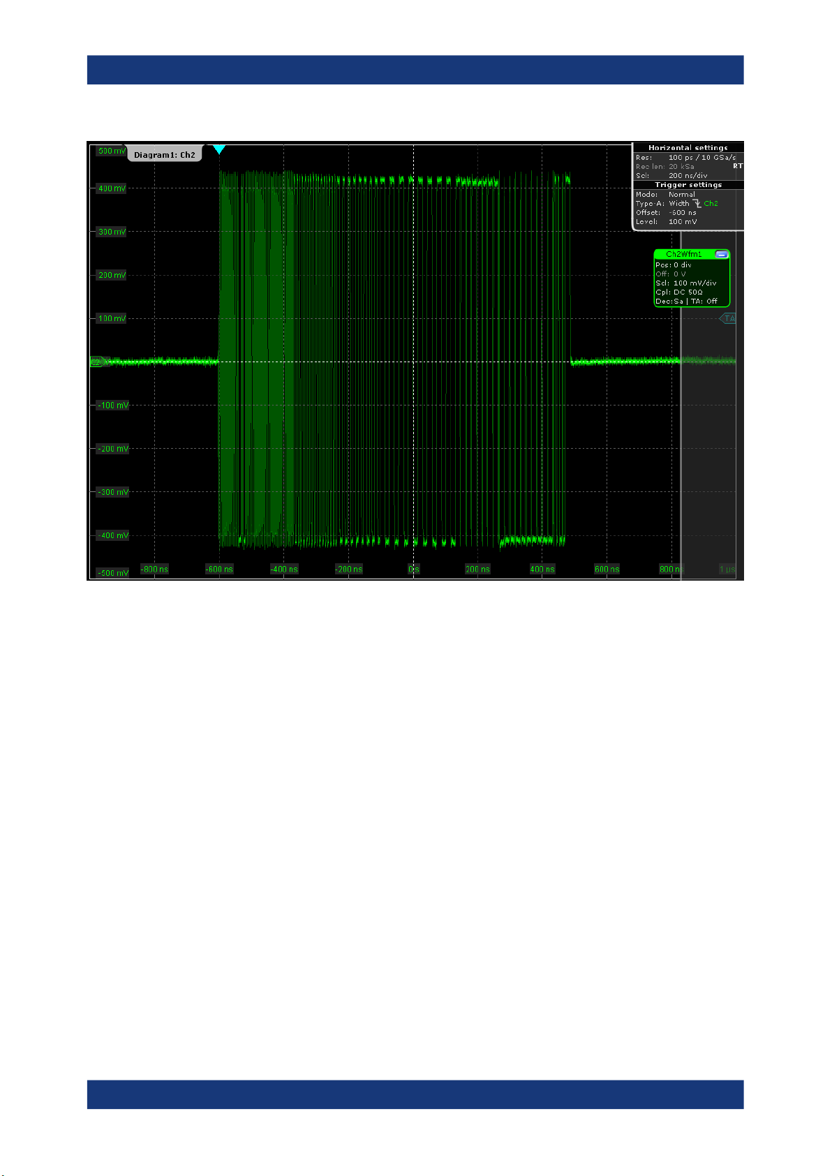
The DUT sends test packets that look like this:
30User Manual 1317.4455.02 ─ 12
Page 31
R&S®RTO-K21, R&S®RTO6-K21, R&S®RTP-K21/-K101
Device Tests
USB2.0
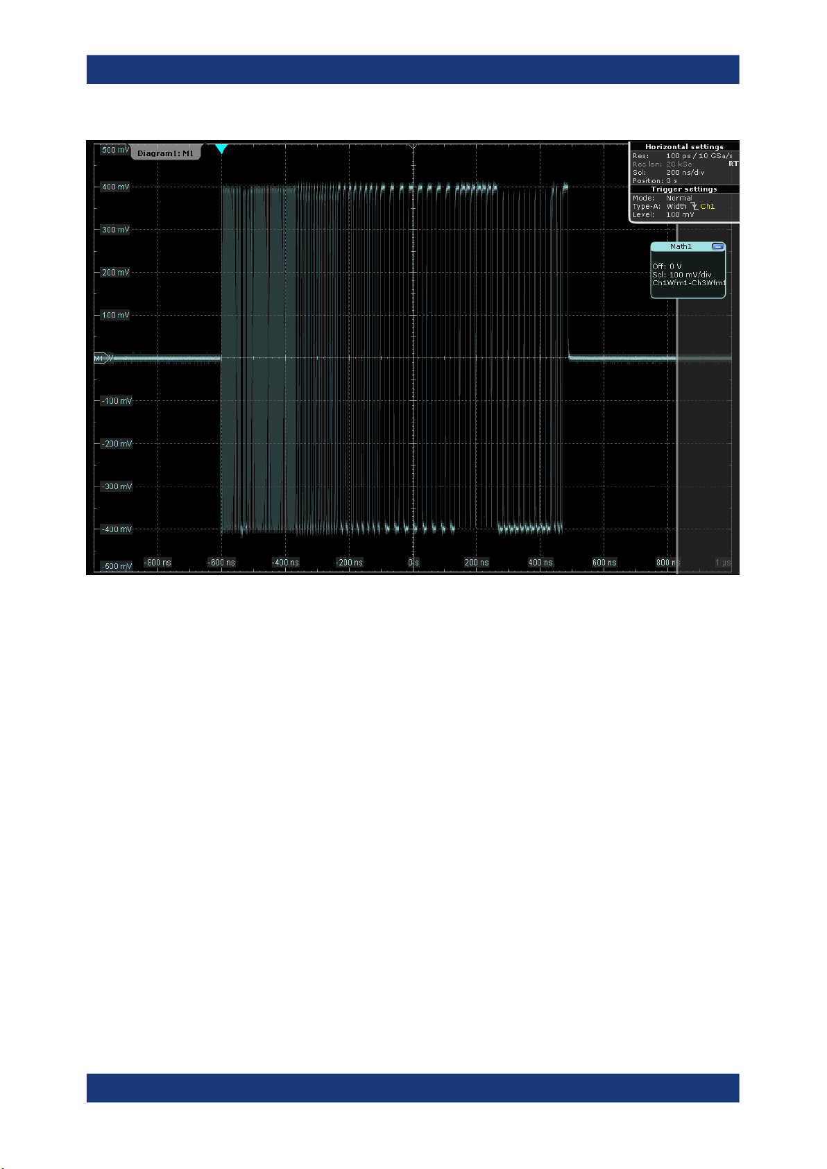
If USB-IF USB2.0 Hi-Speed Signal Quality device test fixture is used, the application uses the built-in math function to create the differential signal of D+ and D-.
The waveform will look like this:
31User Manual 1317.4455.02 ─ 12
Page 32
R&S®RTO-K21, R&S®RTO6-K21, R&S®RTP-K21/-K101
Device Tests
USB2.0
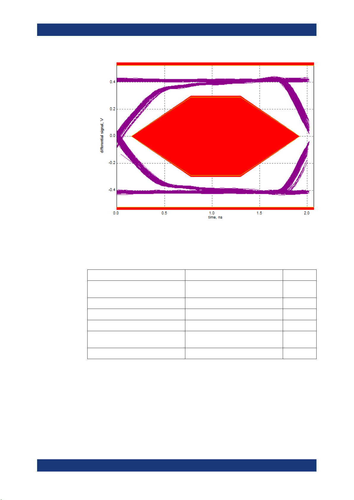
11. These packages are analyzed in an eye diagram.
32User Manual 1317.4455.02 ─ 12
Page 33
R&S®RTO-K21, R&S®RTO6-K21, R&S®RTP-K21/-K101
Device Tests
USB2.0
The results are saved and can be viewed in the report.
4.1.1.2 Packet Parameters
Table 4-2: Equipment
Item Description, model Quantity
Rohde & Schwarz oscilloscope R&S RTO/RTO6/RTP with 4 channels and
DUT the device you want to test 1
Signal quality board, "Device SQ" section R&S RT‑ZF1 1
Differential probe at least 2 GHz bandwidth 1
Host test bed computer any computer with high-speed USB ports
USB cable to connect computer and test fixture 1
Test preparation
Before you run the test, complete the following actions:
●
Initial setup of the equipment, see Chapter 2.2, "Installing Software and License",
on page 8
●
LAN connection of the oscilloscope and the computer running the R&S ScopeSuite, see Chapter 2.5, "Connecting the R&S RTO/RTO6/RTP", on page 10
●
Configure and initiate the test with DUT type = "Device", see Chapter 3.3, "Initiat-
ing the Test", on page 23
1
at least 2 GHz bandwidth
1
and HS Electrical Test Tool
33User Manual 1317.4455.02 ─ 12
Page 34
R&S®RTO-K21, R&S®RTO6-K21, R&S®RTP-K21/-K101
Running the test
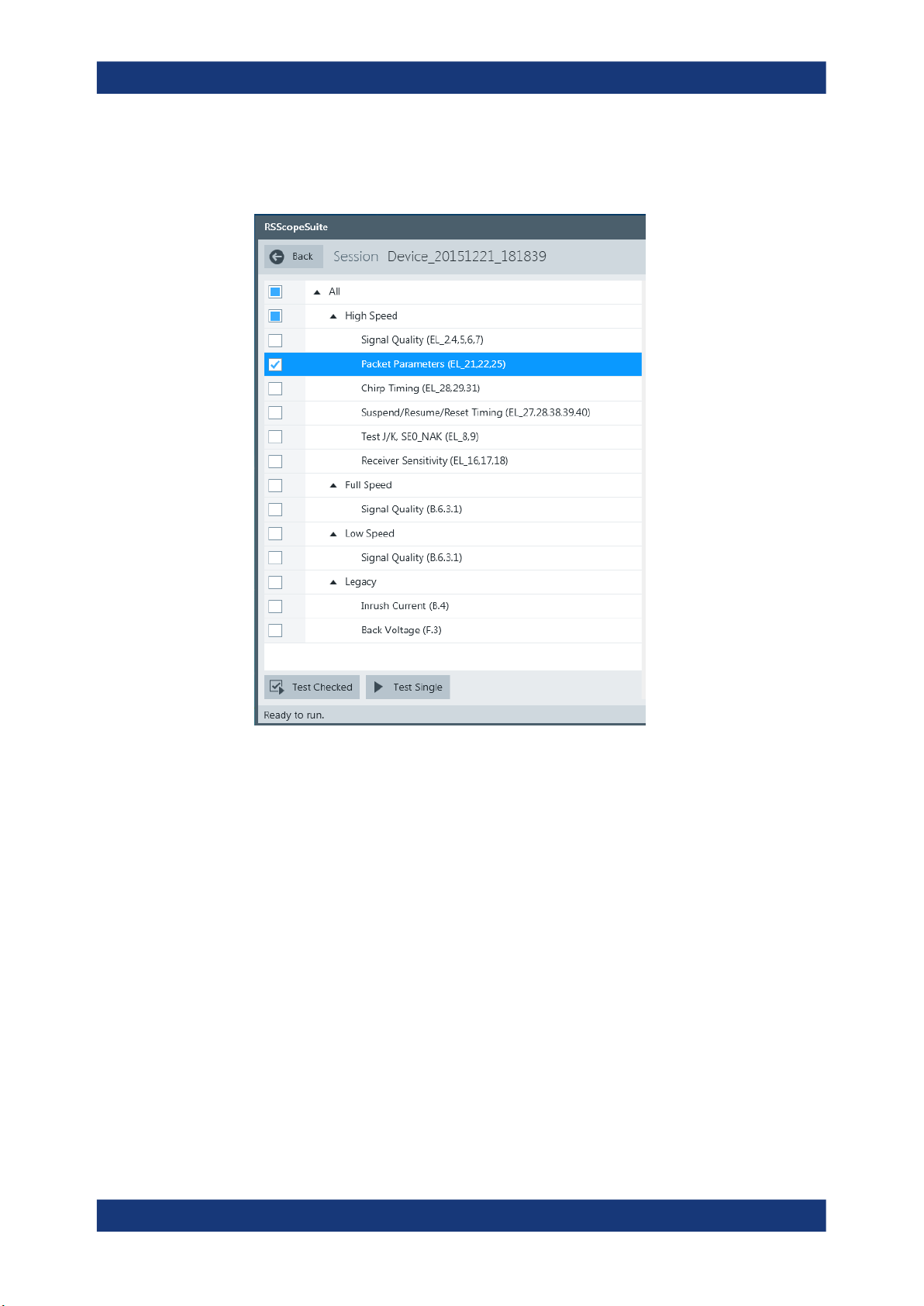
1. Select the "Packet Parameters (EL_21,22,25)" test case and click "Test Single".
Device Tests
USB2.0
2. Connect the DUT to the test fixture as shown in the picture.
34User Manual 1317.4455.02 ─ 12
Page 35
R&S®RTO-K21, R&S®RTO6-K21, R&S®RTP-K21/-K101
Device Tests
USB2.0
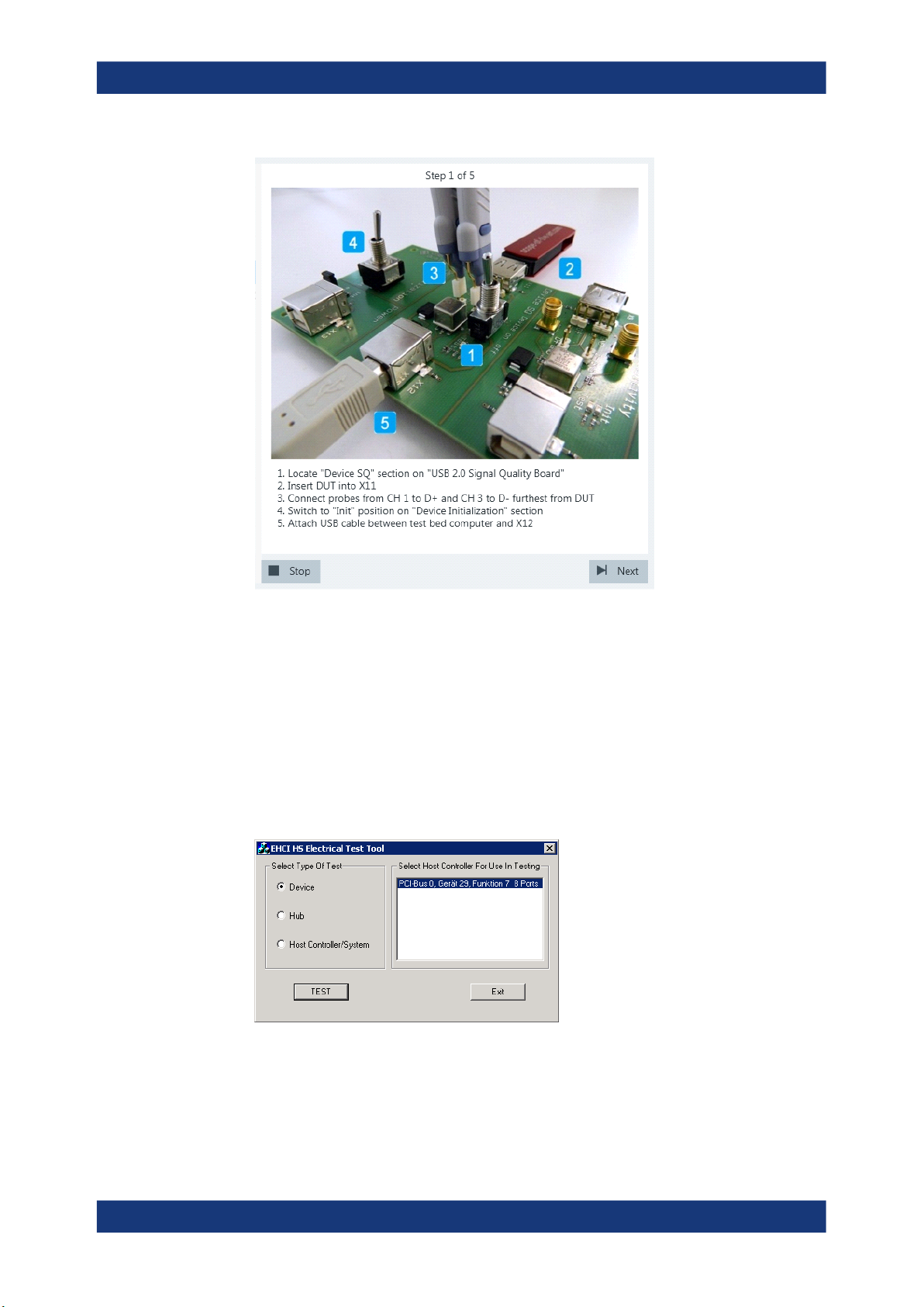
If the DUT has a type A connector attached, plug it into the test fixture directly. Otherwise, connect the DUT to the test fixture using a 4-inch cable.
Use a 1-meter non-captive cable to connect the test bed computer to the test fixture.
3. Click "Next".
4. Start the HS Electrical Test Tool on the test bed computer.
5. Select "Device" on the left side, and the host controller to which the DUT is connec-
ted on the right side.
Note: the values in the list may vary.
6. Click "TEST".
7. Click "Next" in the R&S ScopeSuite.
35User Manual 1317.4455.02 ─ 12
Page 36
R&S®RTO-K21, R&S®RTO6-K21, R&S®RTP-K21/-K101
Device Tests
USB2.0
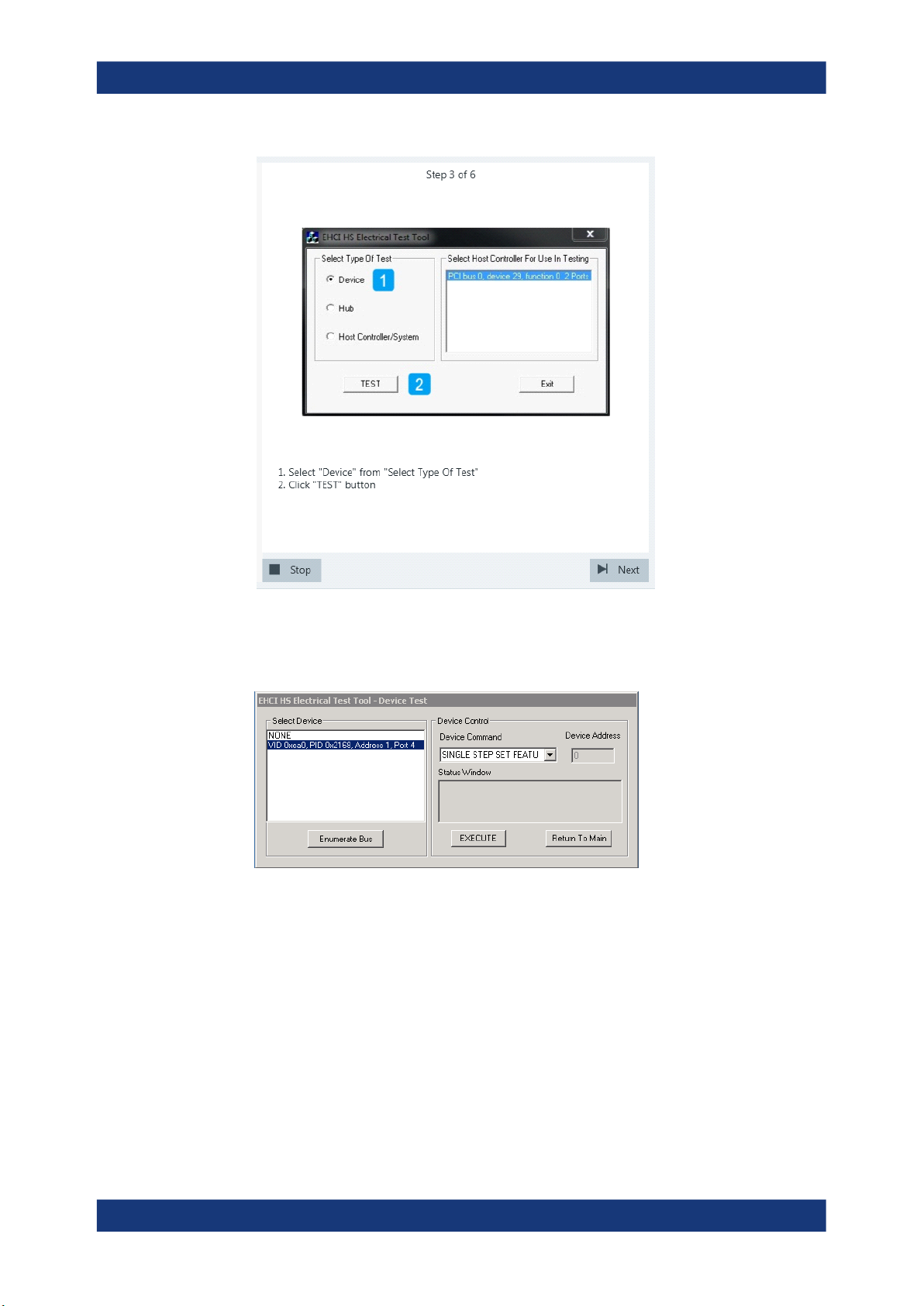
The RTO is set to trigger on the packets sent between host (Set_Feature Packet)
and device.
8. Select "SINGLE STEP SET FEATURE" on the "Device Command" list.
9. Click "EXECUTE" and wait for its change to "Step".
A waveform is captured as pictured below.
36User Manual 1317.4455.02 ─ 12
Page 37
R&S®RTO-K21, R&S®RTO6-K21, R&S®RTP-K21/-K101
Device Tests
USB2.0
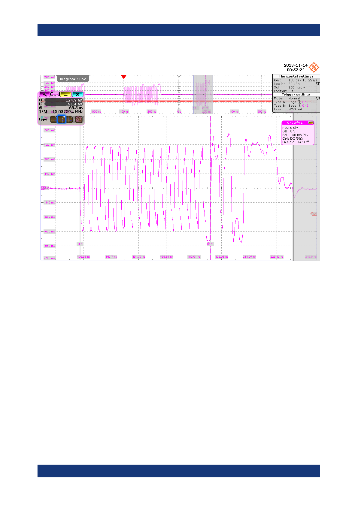
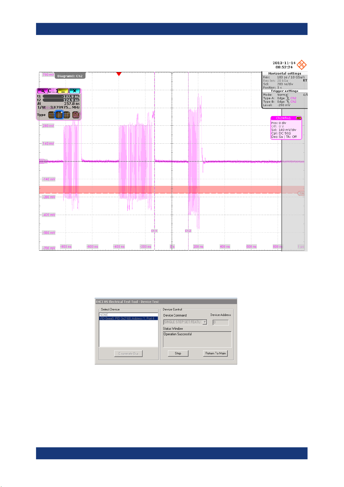
The first packet on the left is an "IN” packet sent by the test bed computer. It is followed by a "Set Feature” packet (middle) also sent from the test bed computer. On
the right you can see the answer from the DUT with higher amplitude than the
packets from the test bed computer.
The application counts the number of bits in the DUT packet SYNC field by measuring the duration of the first 31 pulses. This is EL_21.
37User Manual 1317.4455.02 ─ 12
Page 38
R&S®RTO-K21, R&S®RTO6-K21, R&S®RTP-K21/-K101
Device Tests
USB2.0
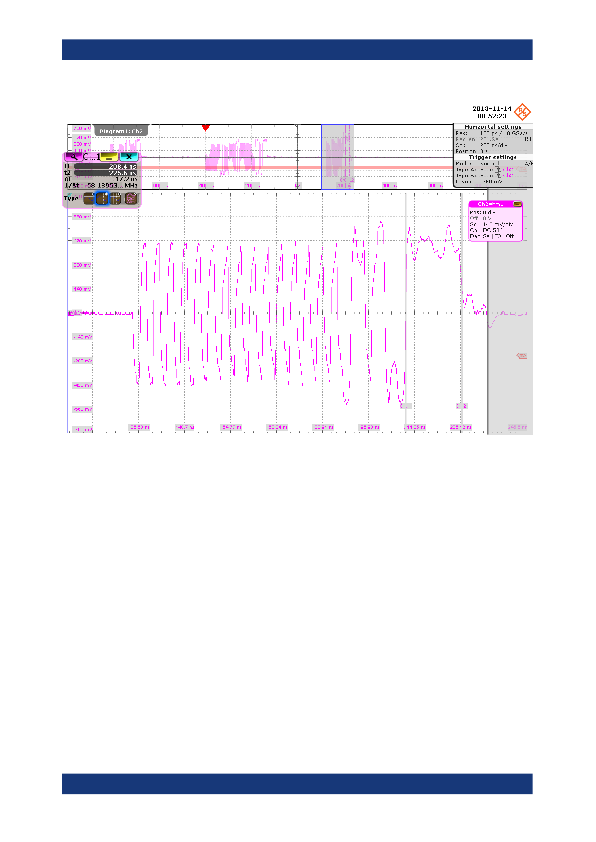
The application counts the number of bits in the DUT packet EOP field by measuring the duration of the widest pulse. This is EL_25.
38User Manual 1317.4455.02 ─ 12
Page 39
R&S®RTO-K21, R&S®RTO6-K21, R&S®RTP-K21/-K101
Device Tests
USB2.0
The application measures the time between the “Set Feature” packet and DUT
packet. This is EL_22.
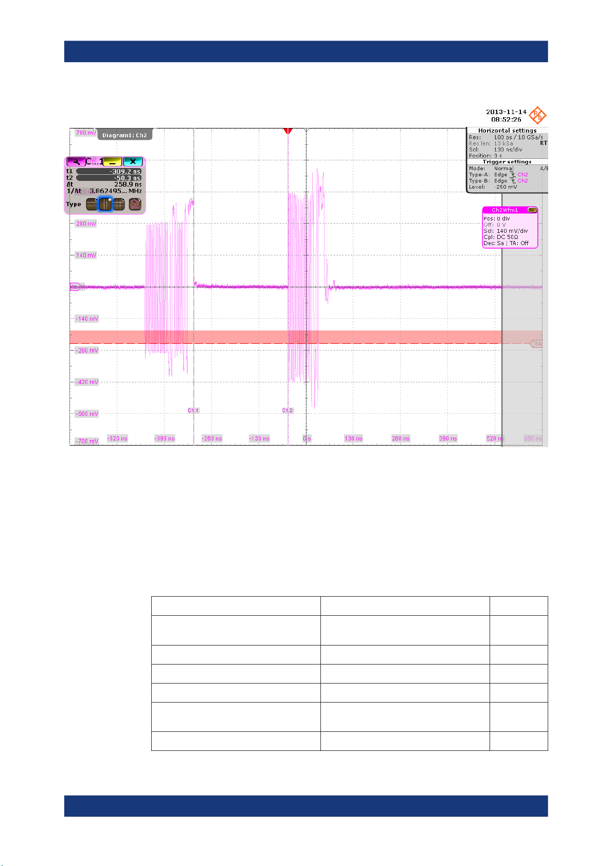
10. Click "Step" and wait until "Operation Successful" is shown under "Status Window".
A waveform is captured as pictured below.
39User Manual 1317.4455.02 ─ 12
Page 40
R&S®RTO-K21, R&S®RTO6-K21, R&S®RTP-K21/-K101
Device Tests
USB2.0
The first packet (left) is an "IN Packet" sent by the host. The second packet with
higher amplitude is the answer from the device. The application measures the time
between the two packets. This is EL_22.
The results are saved and can be viewed in the report.
4.1.1.3 Chirp Timing
Table 4-3: Equipment
Item Description, model Quantity
Rohde & Schwarz oscilloscope R&S RTO/RTO6/RTP with 4 channels and
DUT the device you want to test 1
Signal quality board, "Device SQ" section R&S RT‑ZF1 1
Single-ended probe at least 2 GHz bandwidth 2
Host test bed computer any computer with high-speed USB ports
USB cable to connect computer and test fixture 1
1
at least 2 GHz bandwidth
1
and HS Electrical Test Tool
40User Manual 1317.4455.02 ─ 12
Page 41
R&S®RTO-K21, R&S®RTO6-K21, R&S®RTP-K21/-K101
Test preparation
Before you run the test, complete the following actions:
●
Initial setup of the equipment, see Chapter 2.2, "Installing Software and License",
on page 8
●
LAN connection of the oscilloscope and the computer running the R&S ScopeSuite, see Chapter 2.5, "Connecting the R&S RTO/RTO6/RTP", on page 10
●
Configure and initiate the test with DUT type = "Device", see Chapter 3.3, "Initiat-
ing the Test", on page 23
Running the test
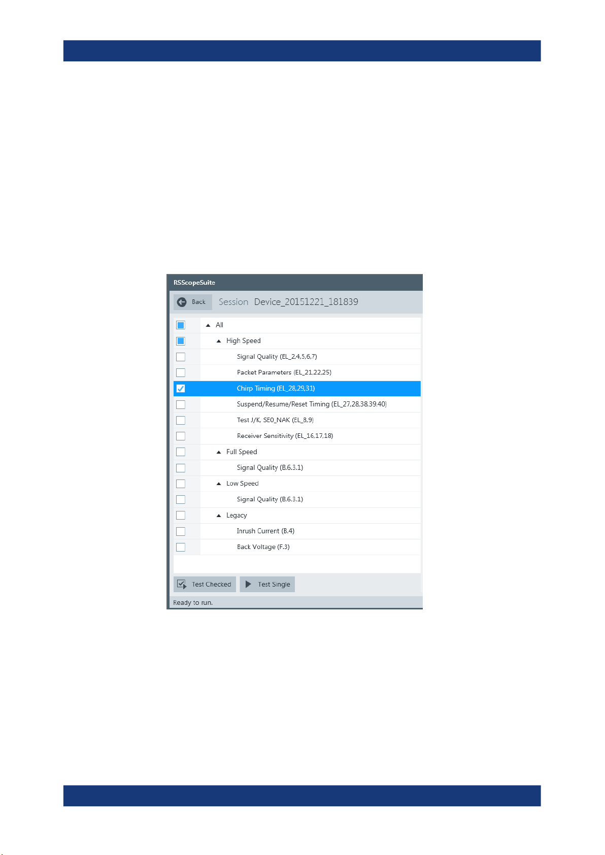
1. Select the "Chirp Timing (EL_28,29,31)" test case and click "Test Single".
Device Tests
USB2.0
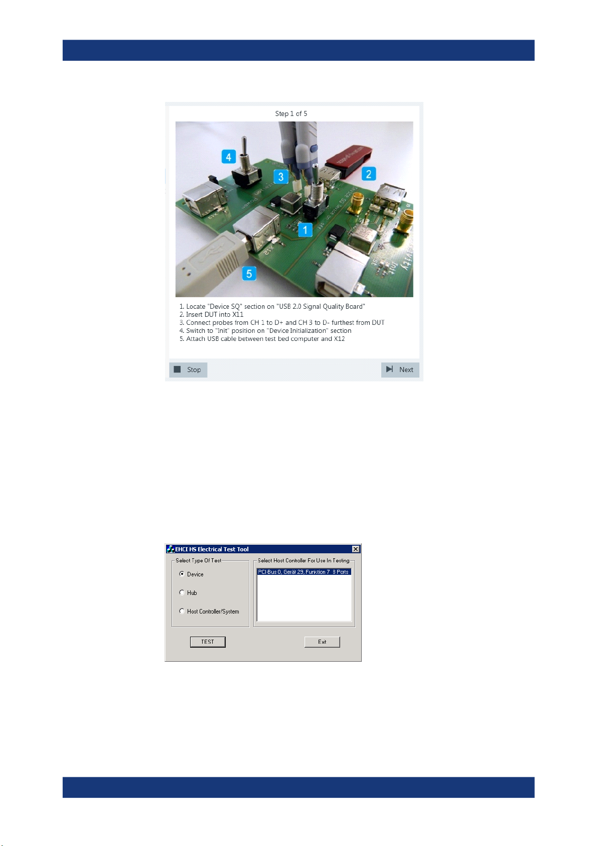
2. Connect the DUT to the test fixture as shown in the picture.
41User Manual 1317.4455.02 ─ 12
Page 42
R&S®RTO-K21, R&S®RTO6-K21, R&S®RTP-K21/-K101
Device Tests
USB2.0
If the DUT has a type A connector attached, plug it into the test fixture directly. Otherwise, connect the DUT to the test fixture using a 4-inch cable.
Use a 1-meter non-captive cable to connect the test bed computer to the test fixture.
3. Click "Next".
4. Start the HS Electrical Test Tool on the test bed computer.
5. Select "Device" on the left side, and the host controller to which the DUT is connec-
ted on the right side.
Note: the values in the list may vary.
6. Click "TEST".
7. Click "Enumerate Bus" in the HS Electrical Test Tool.
42User Manual 1317.4455.02 ─ 12
Page 43
R&S®RTO-K21, R&S®RTO6-K21, R&S®RTP-K21/-K101
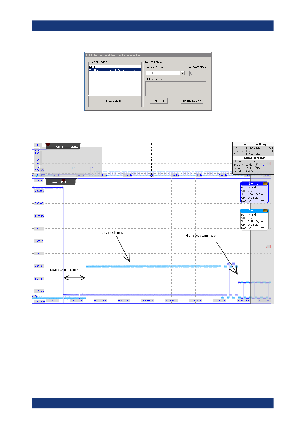
8. Click "Next" in the R&S ScopeSuite.
The Figure 4-5 shows an overview over D+/D- when a host is negotiating highspeed with the device.
Device Tests
USB2.0
Figure 4-5: High-speed communication of host and device
43User Manual 1317.4455.02 ─ 12
Page 44
R&S®RTO-K21, R&S®RTO6-K21, R&S®RTP-K21/-K101
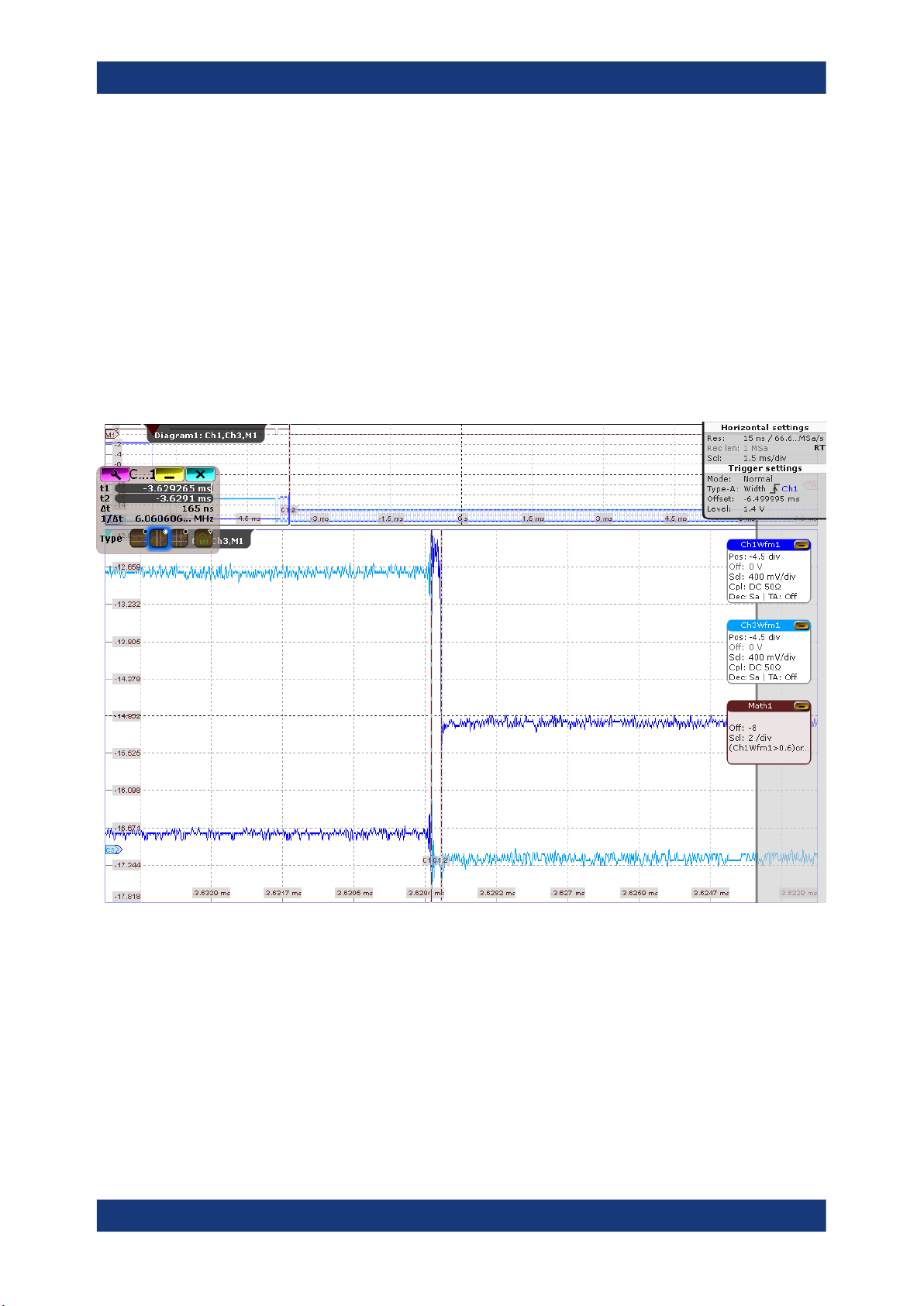
To start a communication with a device, the host pulls down both data lines to low
levels. Big drop of D+ (Ch1Wfm1) is shown on the right side. The device has now
2.5us seconds to respond with a rise of D-. We call this Chirp K Latency and the
EL_28 measurement has to be in the range from 2.5us to 6ms. The host sees this
Device Chirp-K (800mV on D-) and has to respond to it within 1ms and latest within
7ms. The answer is a series of K-J chirp pairs. The length of the Device Chirp-K
time corresponds to the EL_29 measurement. After at least 3 K-J chirp pairs the
device can assume that the host is high speed capable. When sure, the device
applies the 45 Ohm terminations and by this pulls down the voltage of the chirps to
400mV. This drop can be seen in more detail in Figure 4-6. The time from the third
Chirp till the drop has to be in the range from 0s to 500us. We store this measurement under EL_31 High Speed Termination After Chirp.
Device Tests
USB2.0
Figure 4-6: EL_31 chirp drop
The results are saved and can be viewed in the report.
44User Manual 1317.4455.02 ─ 12
Page 45
R&S®RTO-K21, R&S®RTO6-K21, R&S®RTP-K21/-K101
4.1.1.4 Suspend/Resume/Reset Timing
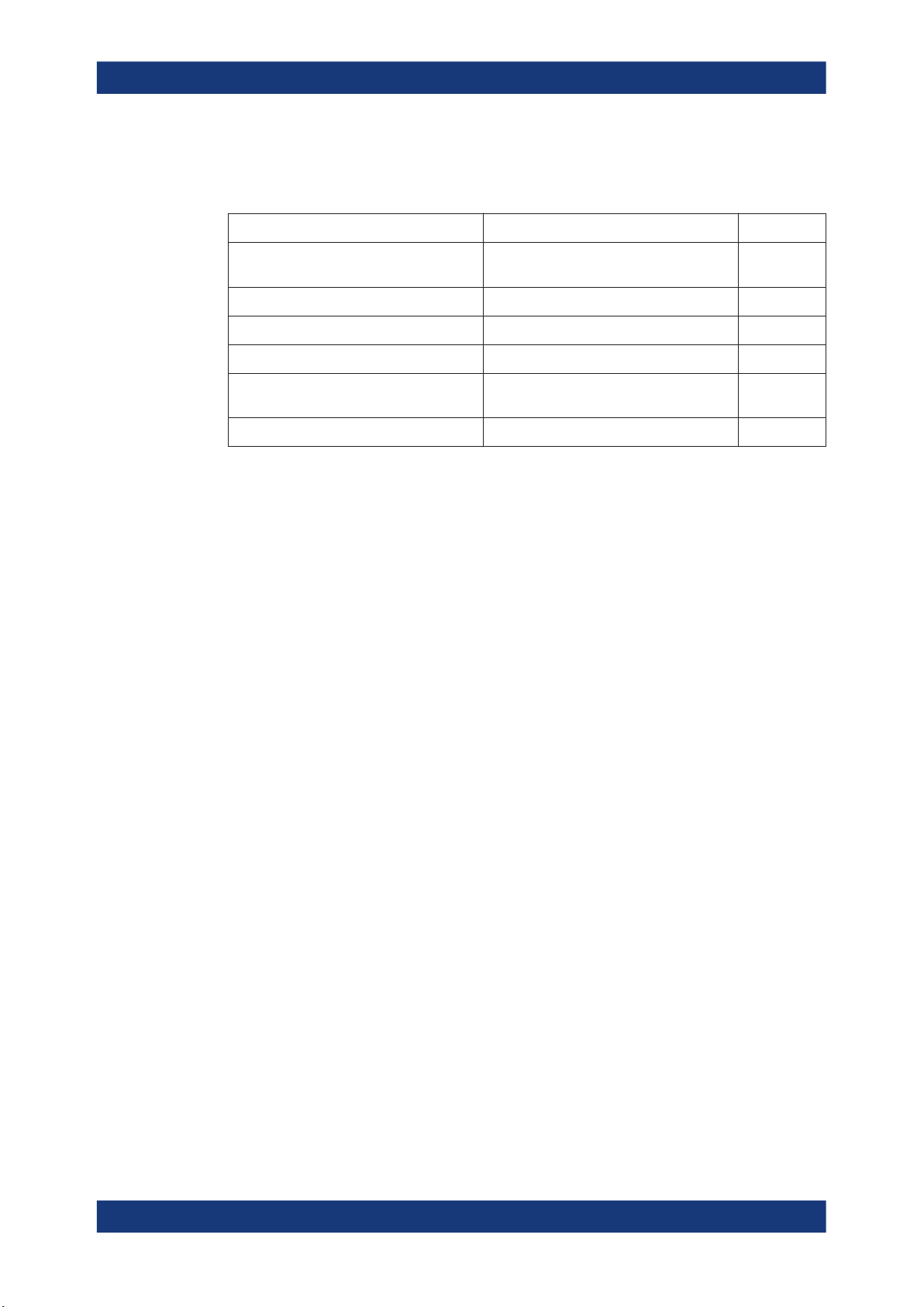
Table 4-4: Equipment
Item Description, model Quantity
Device Tests
USB2.0
Rohde & Schwarz oscilloscope R&S RTO/RTO6/RTP with 4 channels and
at least 2 GHz bandwidth
DUT the device you want to test 1
Signal quality board, "Device SQ" section R&S RT‑ZF1 1
Single-ended probe at least 2 GHz bandwidth 2
Host test bed computer any computer with high-speed USB ports
and HS Electrical Test Tool
USB cable to connect computer and test fixture 1
Test preparation
Before you run the test, complete the following actions:
●
Initial setup of the equipment, see Chapter 2.2, "Installing Software and License",
on page 8
●
LAN connection of the oscilloscope and the computer running the R&S ScopeSuite, see Chapter 2.5, "Connecting the R&S RTO/RTO6/RTP", on page 10
●
Configure and initiate the test with DUT type = "Device", see Chapter 3.3, "Initiat-
ing the Test", on page 23
Running the test
1
1
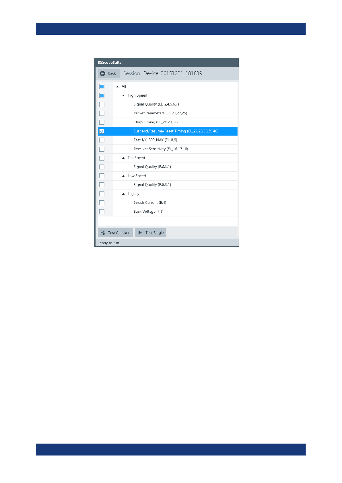
1. Select the "Suspend/Resume/Reset Timing (EL_27,28,38,39,40)" test case and
click "Test Single".
45User Manual 1317.4455.02 ─ 12
Page 46
R&S®RTO-K21, R&S®RTO6-K21, R&S®RTP-K21/-K101
Device Tests
USB2.0
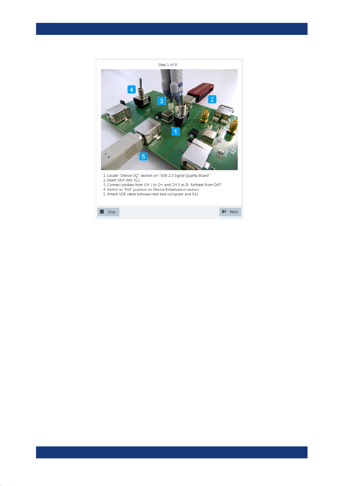
2. Connect the DUT to the test fixture as shown in the picture.
46User Manual 1317.4455.02 ─ 12
Page 47
R&S®RTO-K21, R&S®RTO6-K21, R&S®RTP-K21/-K101
Device Tests
USB2.0
If the DUT has a type A connector attached, plug it into the test fixture directly. Otherwise, connect the DUT to the test fixture using a 4-inch cable.
Use a 1-meter non-captive cable to connect the test bed computer to the test fixture.
3. Click "Next".
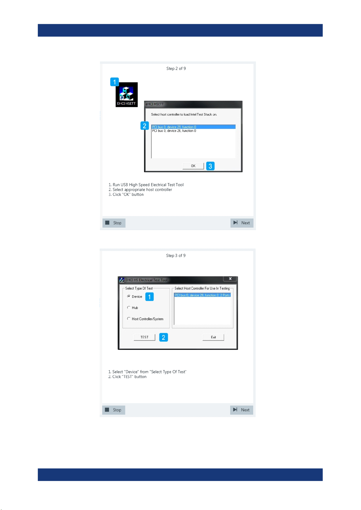
4. Start the HS Electrical Test Tool on the test bed computer.
5. Select the host controller to which the DUT is connected and click OK.
Note: the values in the list may vary.
Click "Next" in the R&S ScopeSuite.
47User Manual 1317.4455.02 ─ 12
Page 48
R&S®RTO-K21, R&S®RTO6-K21, R&S®RTP-K21/-K101
Device Tests
USB2.0
6. Select "Device" on the left side and click "TEST"
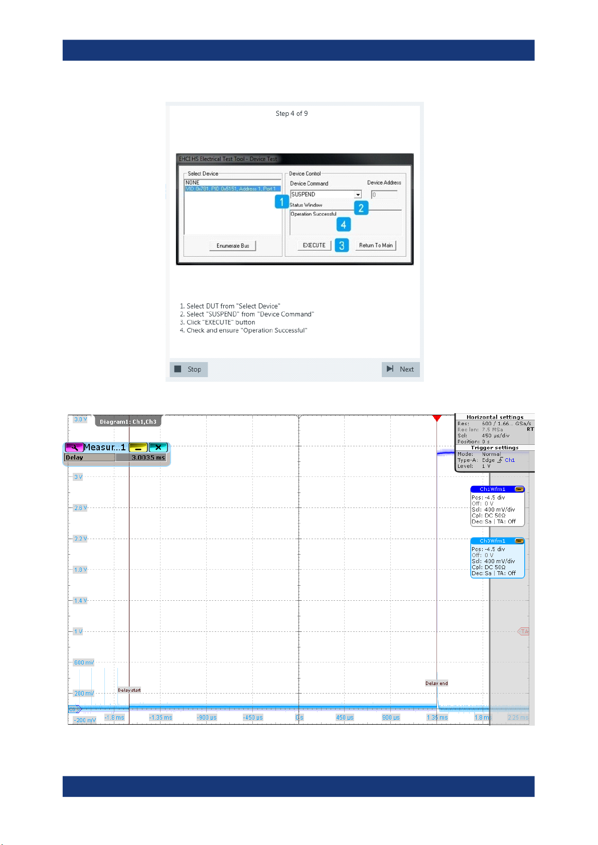
7. Configure the HS Electrical Test Tool as shown in the picture.
48User Manual 1317.4455.02 ─ 12
Page 49
R&S®RTO-K21, R&S®RTO6-K21, R&S®RTP-K21/-K101
Device Tests
USB2.0
Waveforms are captured as pictured below.
49User Manual 1317.4455.02 ─ 12
Page 50
R&S®RTO-K21, R&S®RTO6-K21, R&S®RTP-K21/-K101
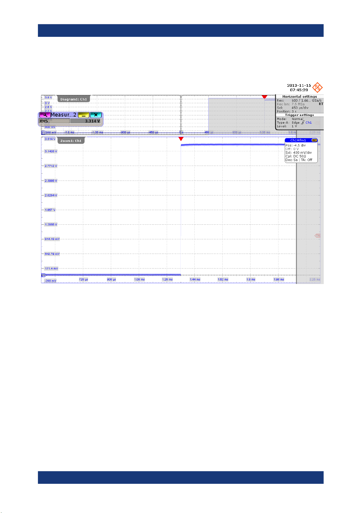
The application measures the time between the last falling edge of the last “Start of
Frame” packet and the start of the suspended state. This is EL_38.
Device Tests
USB2.0
When entering the suspended state, DUT pulls D+ from ~0 V to ~3 V (as shown in
the picture above) and D- remains in ~0 V. The application zooms into the suspended state and measures the voltage of D+/-. This is EL_39.
8. Proceed in the HS Electrical Test Tool as shown in the picture.
50User Manual 1317.4455.02 ─ 12
Page 51
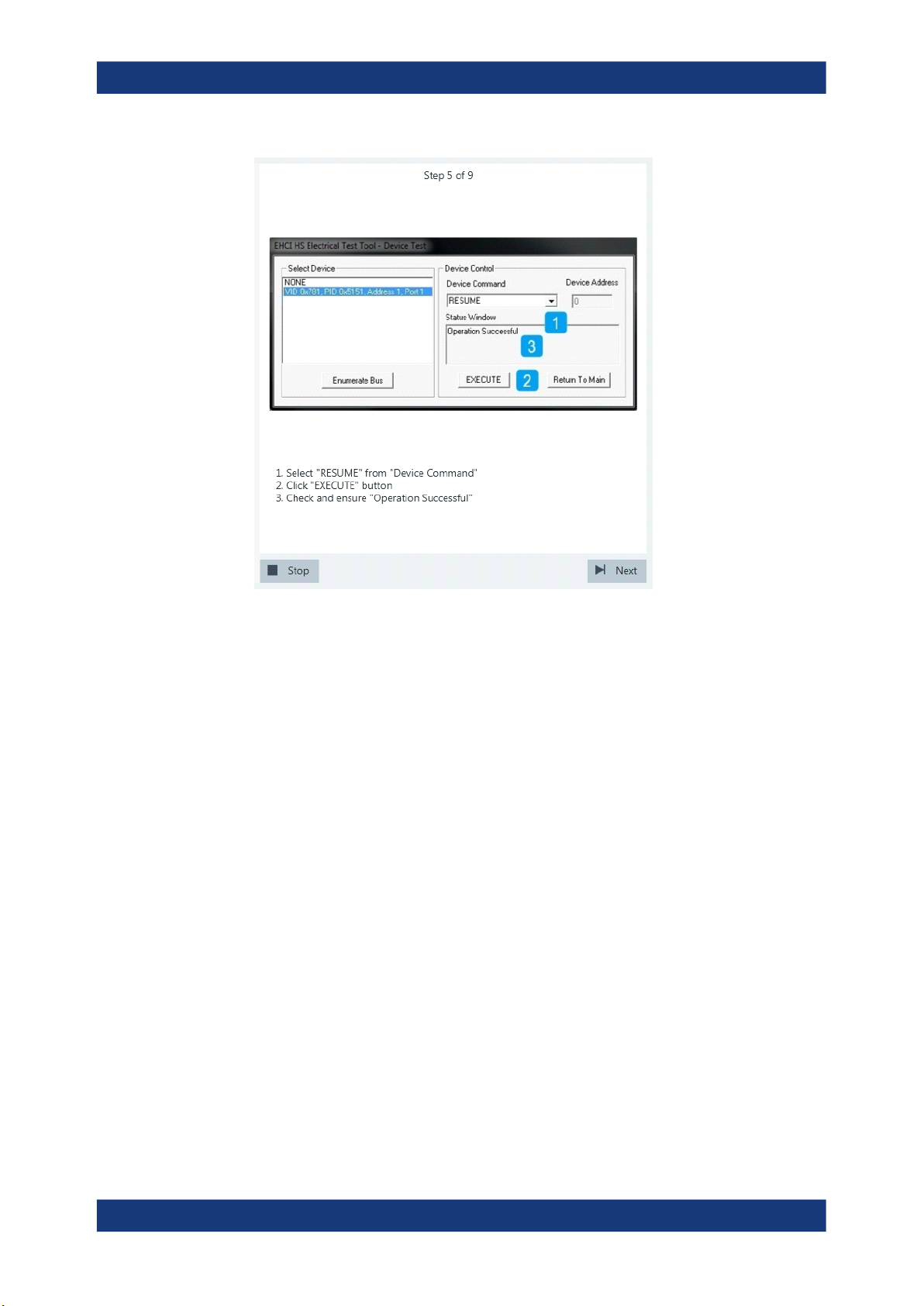
R&S®RTO-K21, R&S®RTO6-K21, R&S®RTP-K21/-K101
Device Tests
USB2.0
Waveforms are captured as pictured below.
51User Manual 1317.4455.02 ─ 12
Page 52
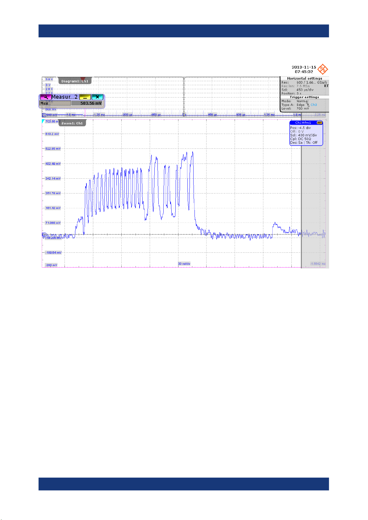
R&S®RTO-K21, R&S®RTO6-K21, R&S®RTP-K21/-K101
Device Tests
USB2.0
52User Manual 1317.4455.02 ─ 12
Page 53
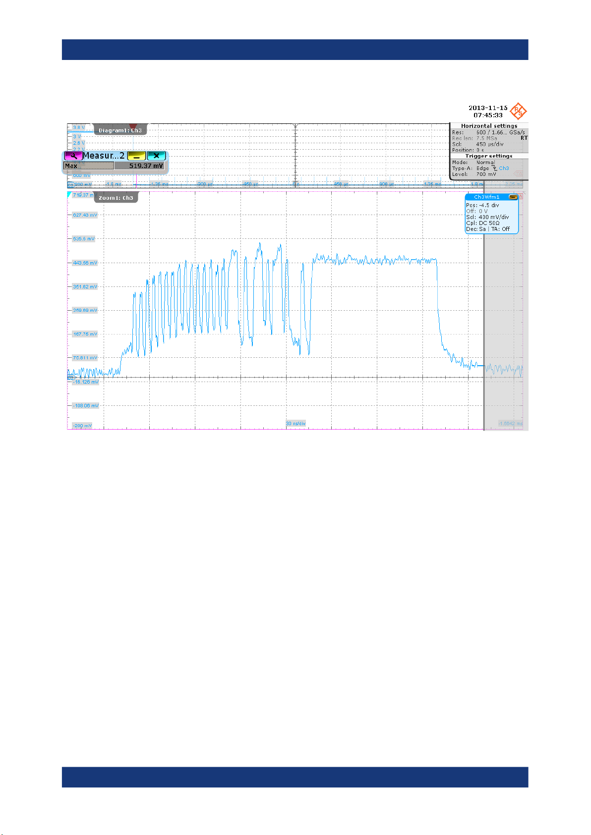
R&S®RTO-K21, R&S®RTO6-K21, R&S®RTP-K21/-K101
Device Tests
USB2.0
The application zooms into the first “Start of Frame” packet and measures the maximum voltage of D+ and D-. This is EL_40.
9. Proceed in the HS Electrical Test Tool as shown in the picture.
53User Manual 1317.4455.02 ─ 12
Page 54
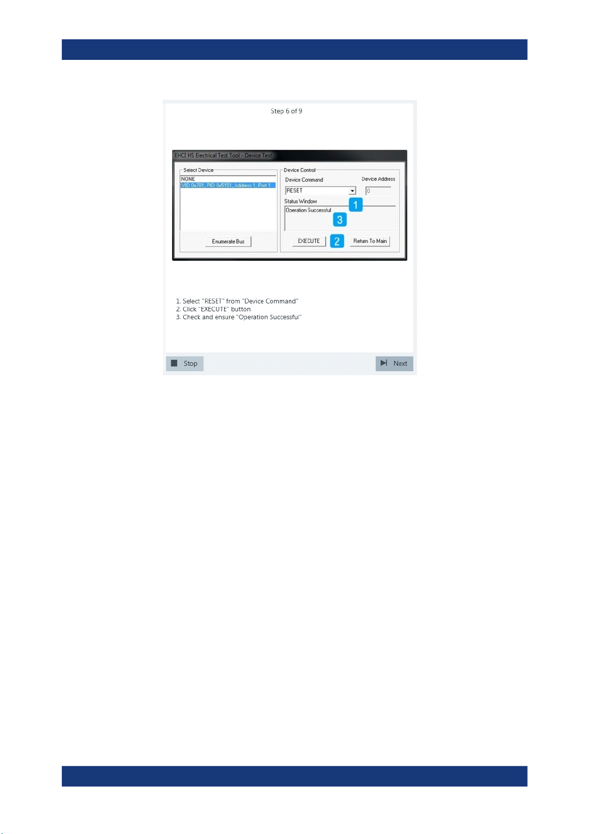
R&S®RTO-K21, R&S®RTO6-K21, R&S®RTP-K21/-K101
Device Tests
USB2.0
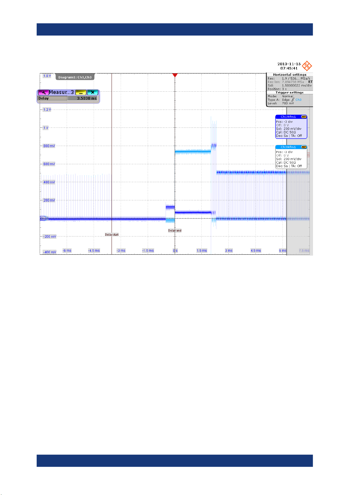
A waveform is captured as pictured below.
54User Manual 1317.4455.02 ─ 12
Page 55
R&S®RTO-K21, R&S®RTO6-K21, R&S®RTP-K21/-K101
Device Tests
USB2.0
The application measures the time between the DUT reset from the non-suspended state (i.e., the last falling edge of the last “Start of Frame” packet) and the start
of the chirp handshake (i.e., the assertion of Chirp K). This is EL_27.
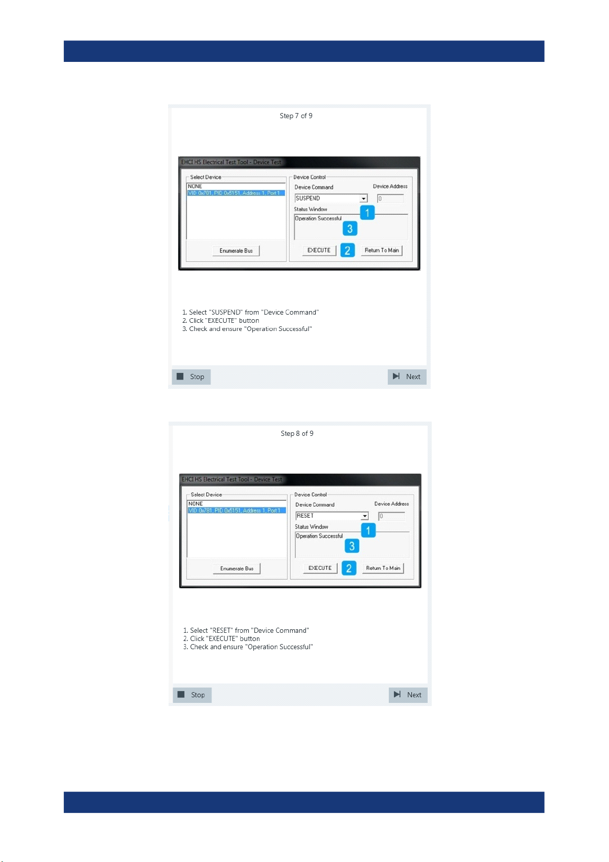
10. Proceed in the HS Electrical Test Tool as shown in the picture.
55User Manual 1317.4455.02 ─ 12
Page 56
R&S®RTO-K21, R&S®RTO6-K21, R&S®RTP-K21/-K101
Device Tests
USB2.0
11. Proceed in the HS Electrical Test Tool as shown in the picture.
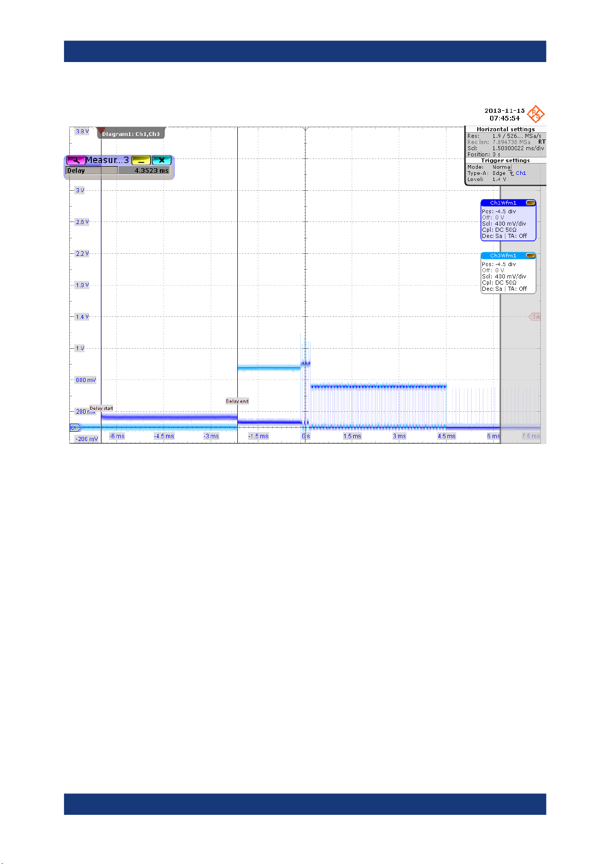
Waveforms are captured as pictured below.
56User Manual 1317.4455.02 ─ 12
Page 57
R&S®RTO-K21, R&S®RTO6-K21, R&S®RTP-K21/-K101
Device Tests
USB2.0
The application measures the time between the DUT reset from the suspended
state (i.e., D+ pulls from ~+3 V to ~0 V) and the start of the chirp handshake (i.e,
the assertion of Chirp K). This is EL_28.
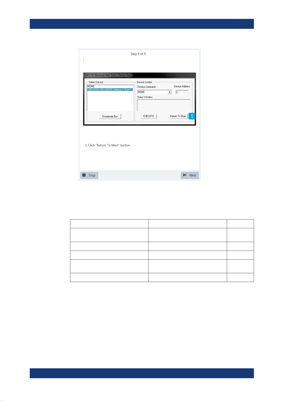
12. Finish the test as shown in the picture.
57User Manual 1317.4455.02 ─ 12
Page 58
R&S®RTO-K21, R&S®RTO6-K21, R&S®RTP-K21/-K101
Device Tests
USB2.0
The results are saved and can be viewed in the report.
4.1.1.5 Test J/K, SE0_NAK
Table 4-5: Equipment
Item Description, model Quantity
Rohde & Schwarz oscilloscope R&S RTO/RTO6/RTP with 4 channels and
Signal quality board, "Device SQ" section R&S RT‑ZF1 1
Single-ended probe at least 2 GHz bandwidth 2
Host test bed computer any computer with high-speed USB ports
USB cable 1.3 m to connect computer and test fixture 1
Test preparation
Before you run the test, complete the following actions:
●
Initial setup of the equipment, see Chapter 2.2, "Installing Software and License",
on page 8
●
LAN connection of the oscilloscope and the computer running the R&S ScopeSuite, see Chapter 2.5, "Connecting the R&S RTO/RTO6/RTP", on page 10
●
Configure and initiate the test with DUT type = "Device", see Chapter 3.3, "Initiat-
ing the Test", on page 23
1
at least 2 GHz bandwidth
1
and HS Electrical Test Tool
58User Manual 1317.4455.02 ─ 12
Page 59
R&S®RTO-K21, R&S®RTO6-K21, R&S®RTP-K21/-K101
Running the test
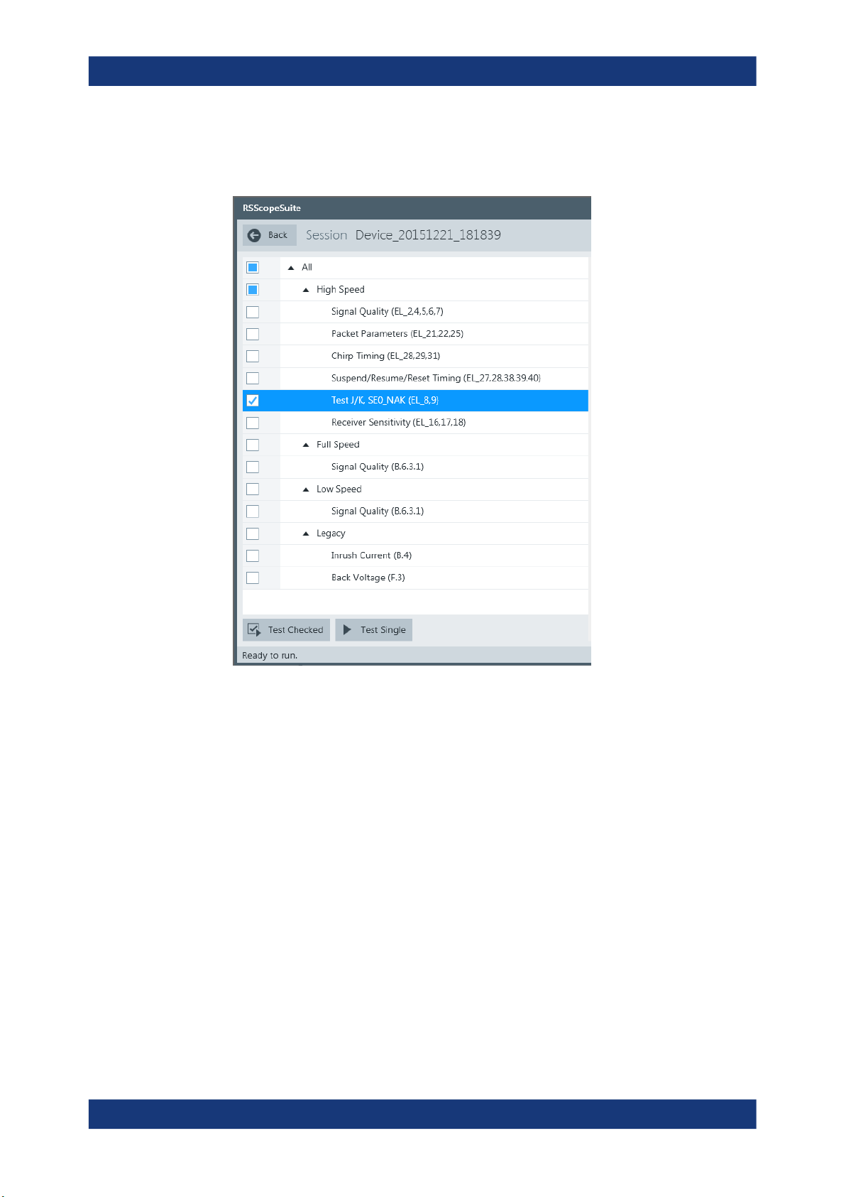
1. Select the "Test J/K, SE0_NAK" test case and click "Test Single".
Device Tests
USB2.0
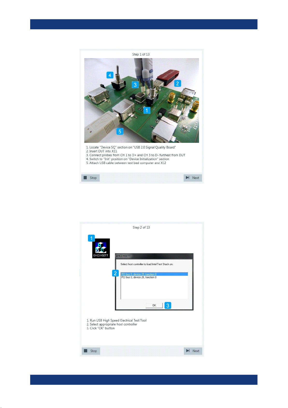
2. Connect the DUT to the test fixture as shown in the picture and click "Next".
59User Manual 1317.4455.02 ─ 12
Page 60
R&S®RTO-K21, R&S®RTO6-K21, R&S®RTP-K21/-K101
Device Tests
USB2.0
3. Start the HS Electrical Test Tool on the test bed computer.
4. Select the host controller to which the DUT is connected and click OK.
Note: the values in the list may vary.
Click "Next" in the R&S ScopeSuite.
60User Manual 1317.4455.02 ─ 12
Page 61
R&S®RTO-K21, R&S®RTO6-K21, R&S®RTP-K21/-K101
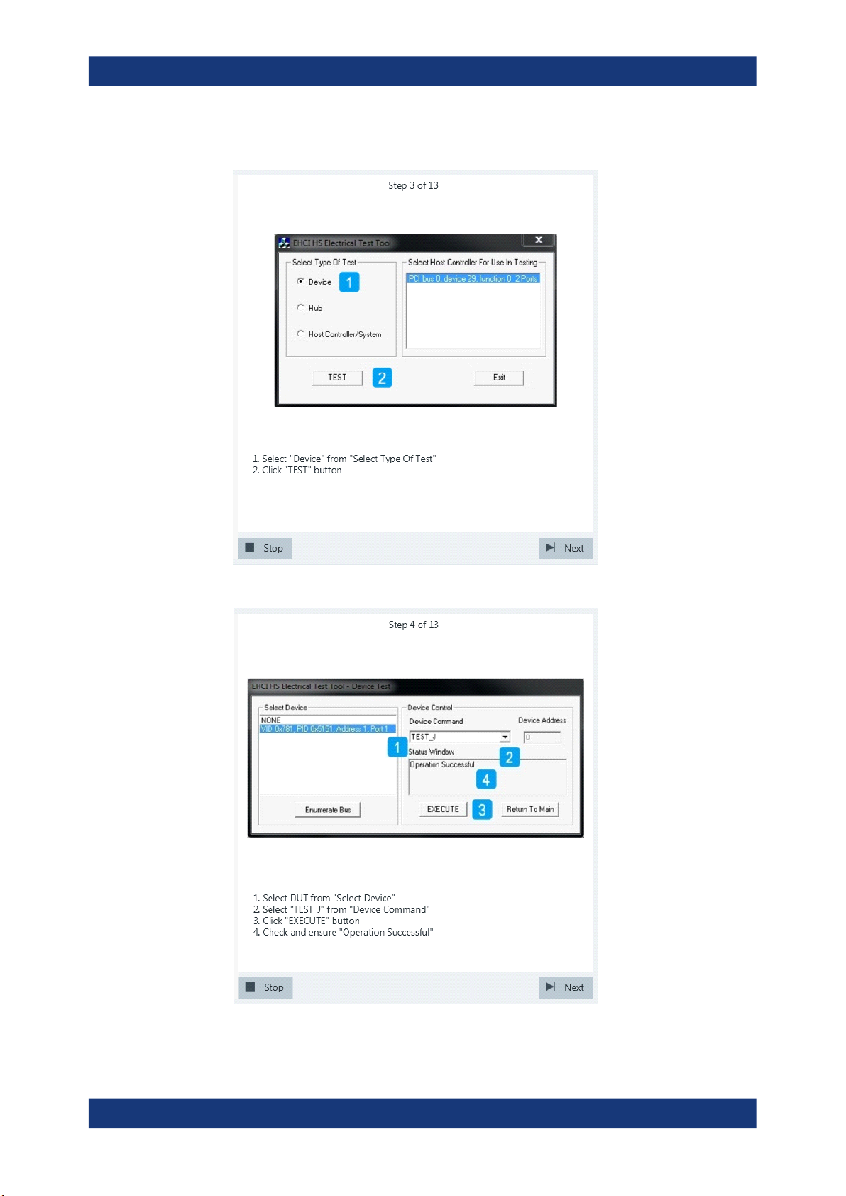
5. Select "Device" on the left side and click "TEST"
Device Tests
USB2.0
6. Configure the HS Electrical Test Tool as shown in the picture.
61User Manual 1317.4455.02 ─ 12
Page 62
R&S®RTO-K21, R&S®RTO6-K21, R&S®RTP-K21/-K101
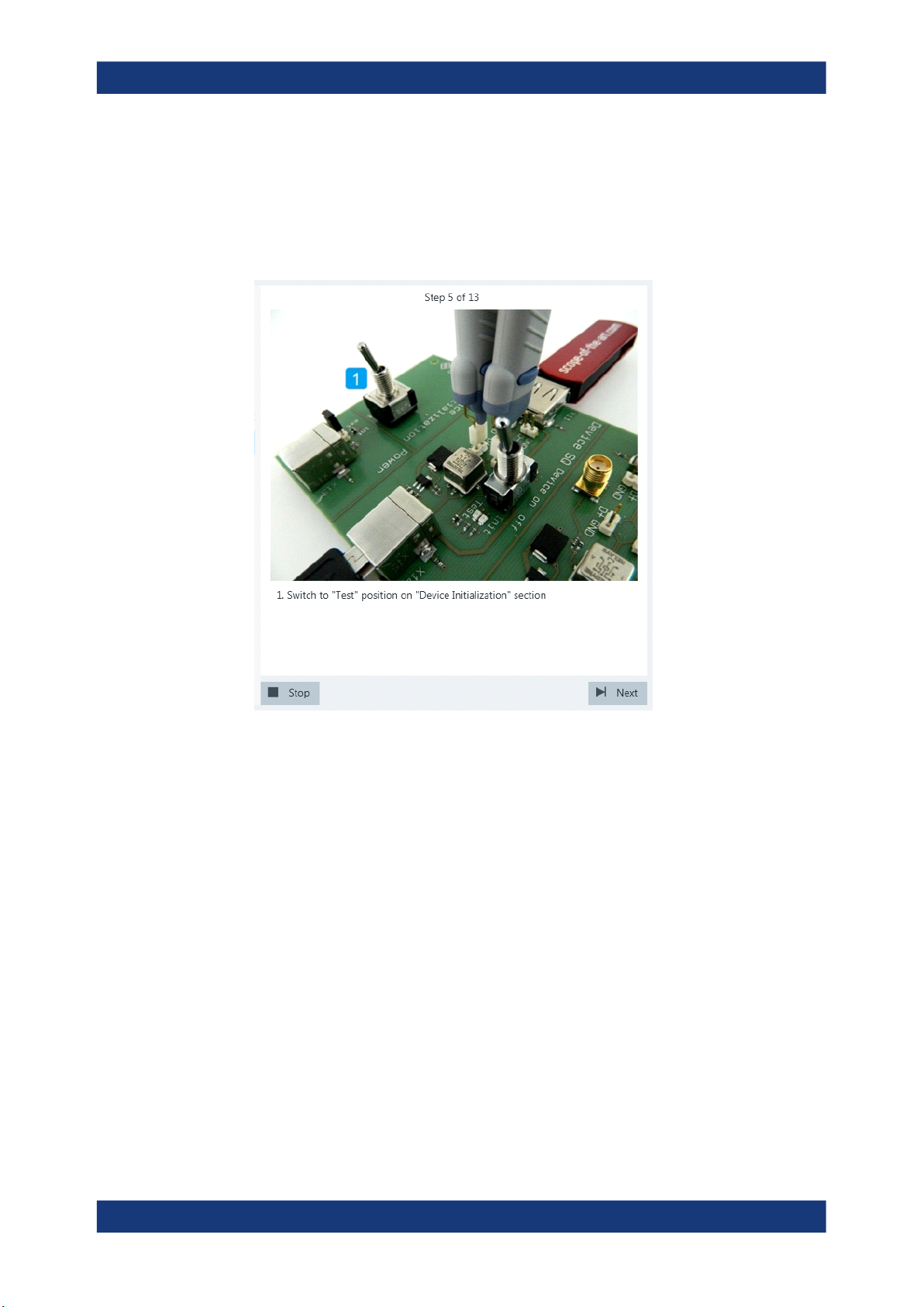
If the DUT has a type A connector attached, plug it into the test fixture directly. Otherwise, connect the DUT to the test fixture using a 4-inch cable.
Use a 1-meter non-captive cable to connect the test bed computer to the test fixture.
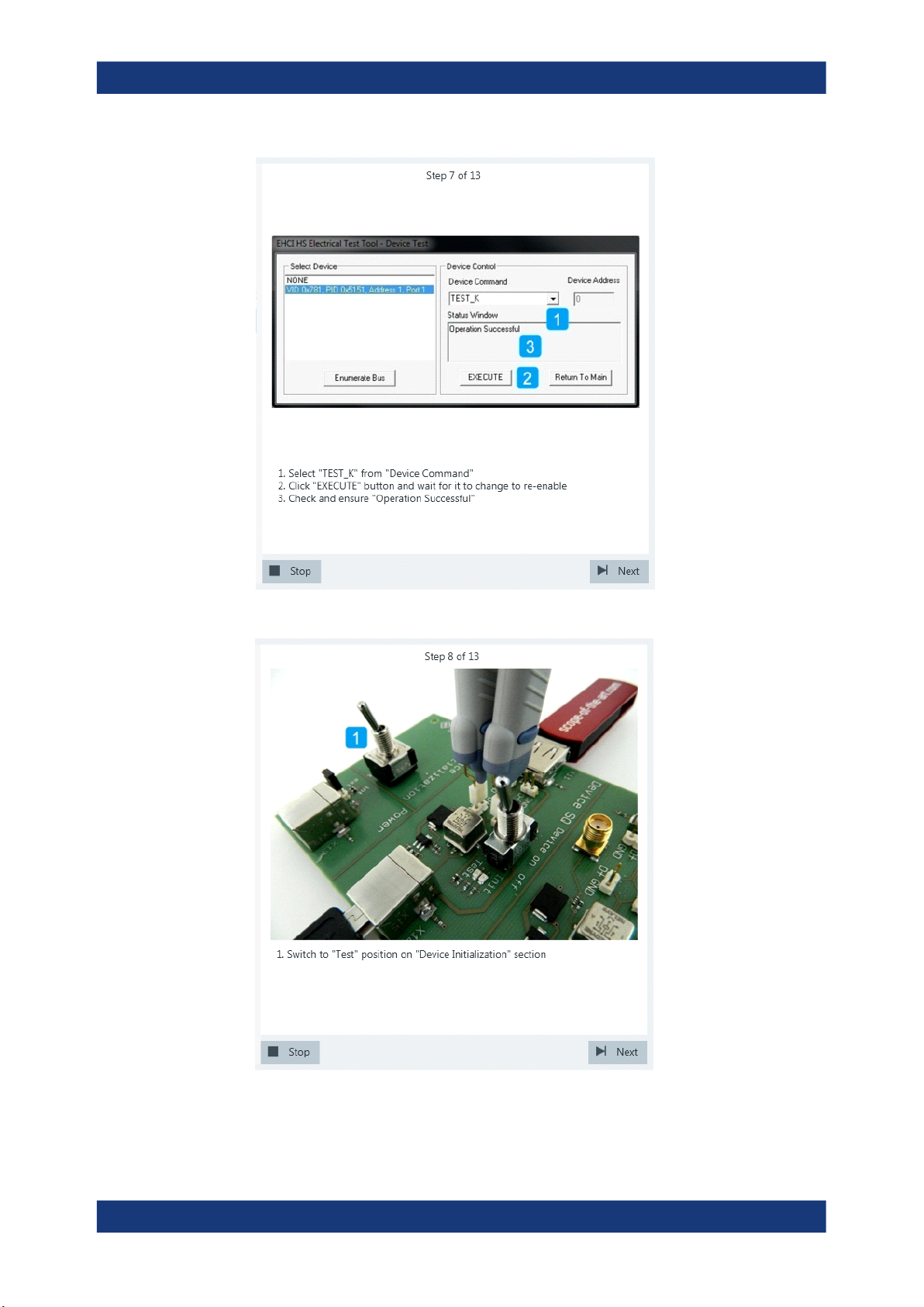
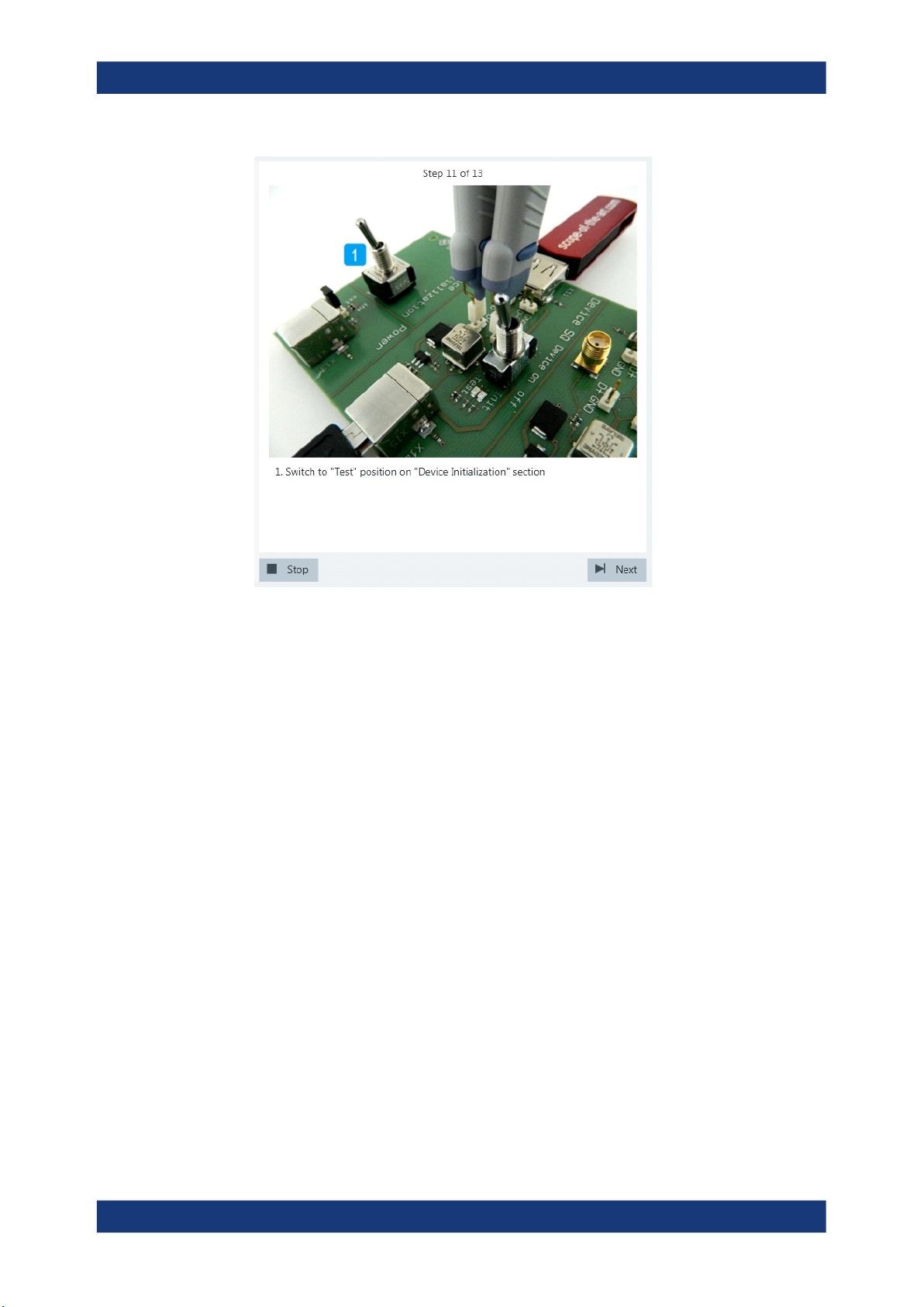
7. Switch the "Device Initialization" switch to "Test" position.
Device Tests
USB2.0
The probe at least 2 GHz bandwidth contains a built-in digital voltmeter known as
ProbeMeter. The application automatically reads the voltages of D+ and D- from
the ProbeMeter. However, if the user has selected "Digital Multimeter (Manual)" in
the test configuration (see Chapter 3.2, "Configuring the Test", on page 16), the
application prompts the user to enter the voltages of D+ and D-.
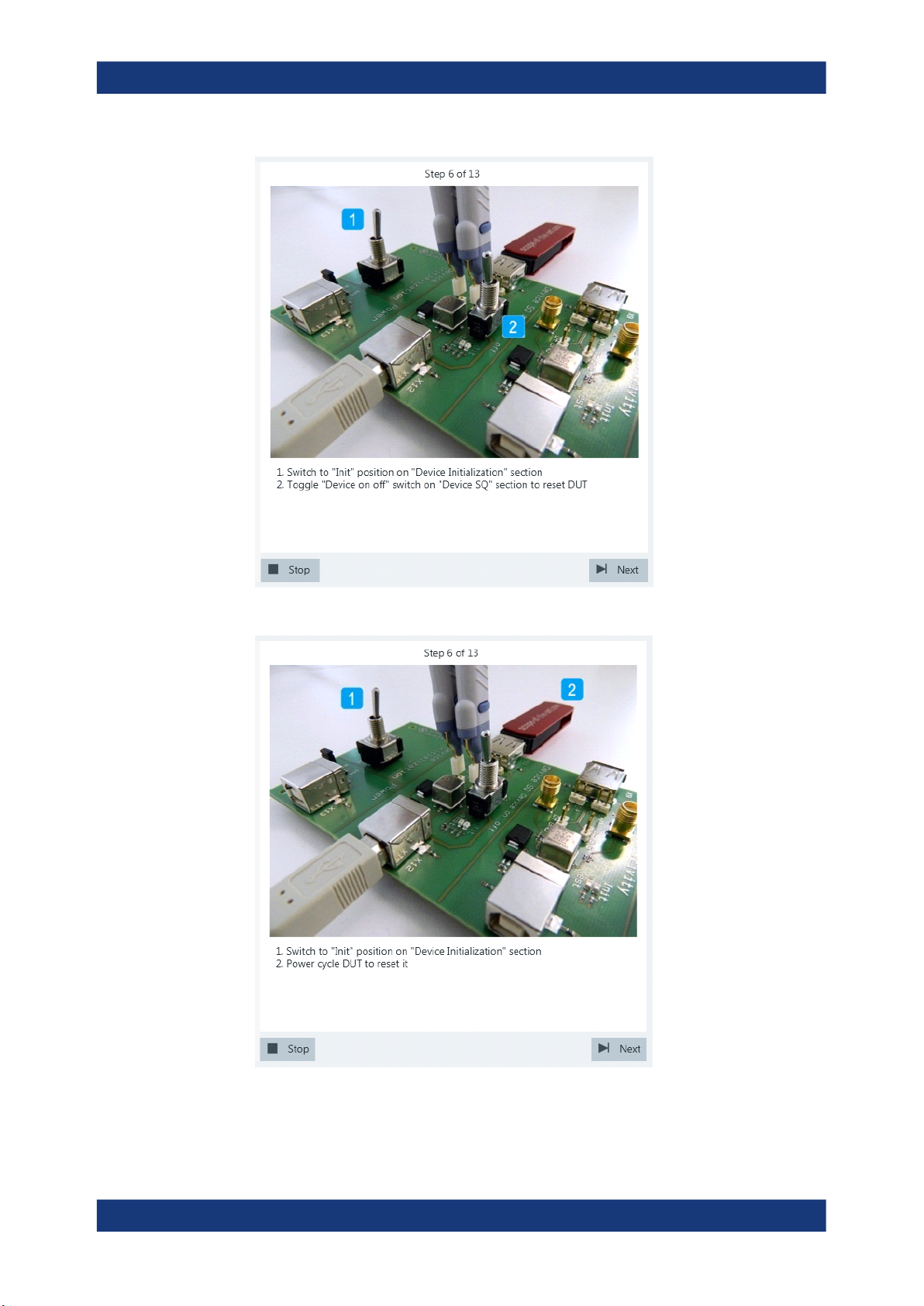
8. Switch the "Device Initialization" switch to "Init" position and reset the DUT. If the
DUT is bus-powered, simply toggle the "Device on off" switch.
62User Manual 1317.4455.02 ─ 12
Page 63
R&S®RTO-K21, R&S®RTO6-K21, R&S®RTP-K21/-K101
Device Tests
USB2.0
If the DUT is self-powered, switch it off and switch it back on.
9. Configure the HS Electrical Test Tool as shown in the picture and execute the test.
63User Manual 1317.4455.02 ─ 12
Page 64
R&S®RTO-K21, R&S®RTO6-K21, R&S®RTP-K21/-K101
Device Tests
USB2.0
10. Switch the "Device Initialization" switch to "Test" position.
If the user has selected "Digital Multimeter (Manual)" in the test configuration (see
Chapter 3.2, "Configuring the Test", on page 16), the application prompts the user
64User Manual 1317.4455.02 ─ 12
Page 65
R&S®RTO-K21, R&S®RTO6-K21, R&S®RTP-K21/-K101
to enter the voltages of D+ and D-. Otherwise it automatically reads them from the
ProbeMeter.
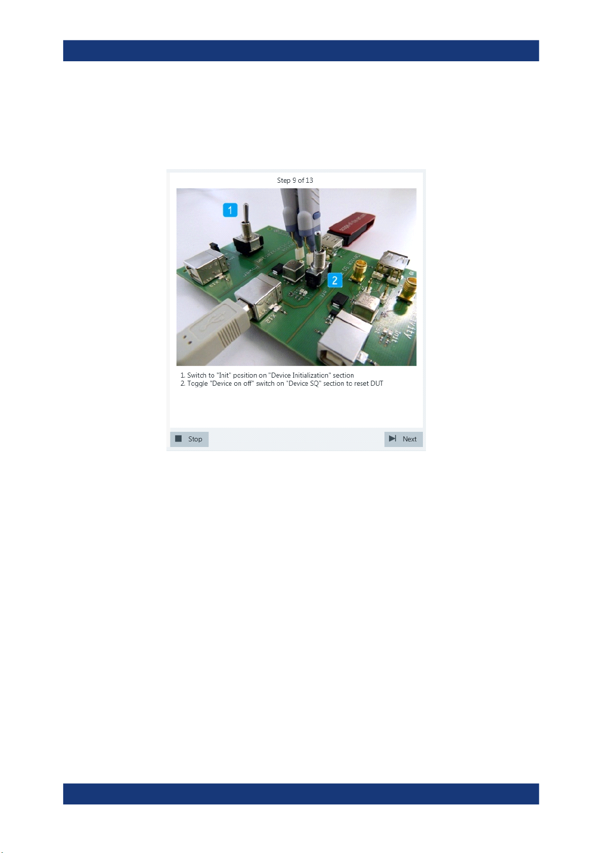
11. Switch the "Device Initialization" switch to the "Init" position and reset the DUT.
If the DUT is bus-powered, simply toggle the "Device on off" switch.
Device Tests
USB2.0
If the DUT is self-powered, switch it off and switch it back on.
65User Manual 1317.4455.02 ─ 12
Page 66
R&S®RTO-K21, R&S®RTO6-K21, R&S®RTP-K21/-K101
Device Tests
USB2.0
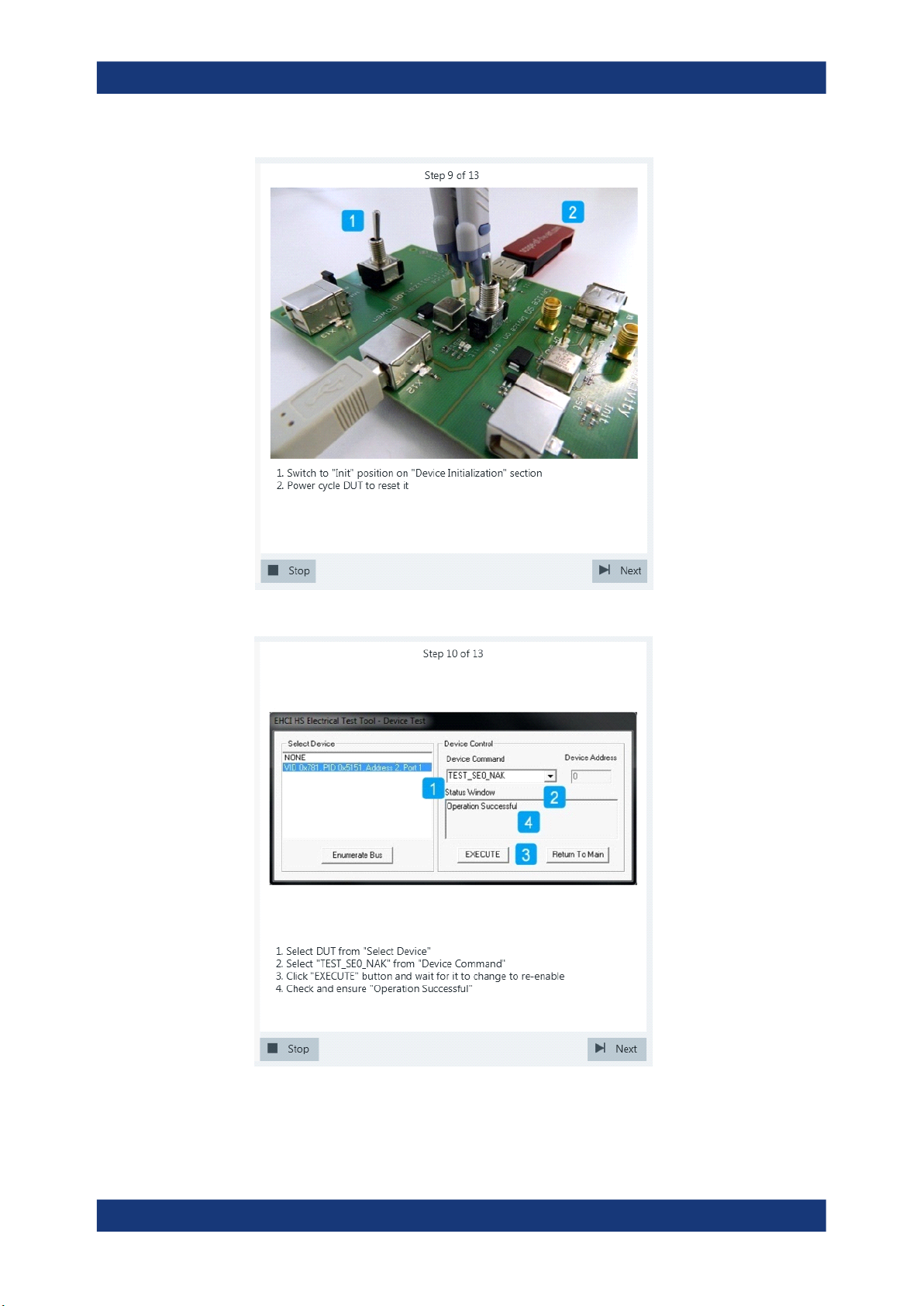
12. Configure the HS Electrical Test Tool as shown in the picture and execute the test.
13. Switch the "Device Initialization" switch to "Test" position.
66User Manual 1317.4455.02 ─ 12
Page 67
R&S®RTO-K21, R&S®RTO6-K21, R&S®RTP-K21/-K101
Device Tests
USB2.0
If the user has selected "Digital Multimeter (Manual)" in the test configuration (see
Chapter 3.2, "Configuring the Test", on page 16), the application prompts the user
to enter the voltages of D+ and D-. Otherwise it automatically reads them from the
ProbeMeter.
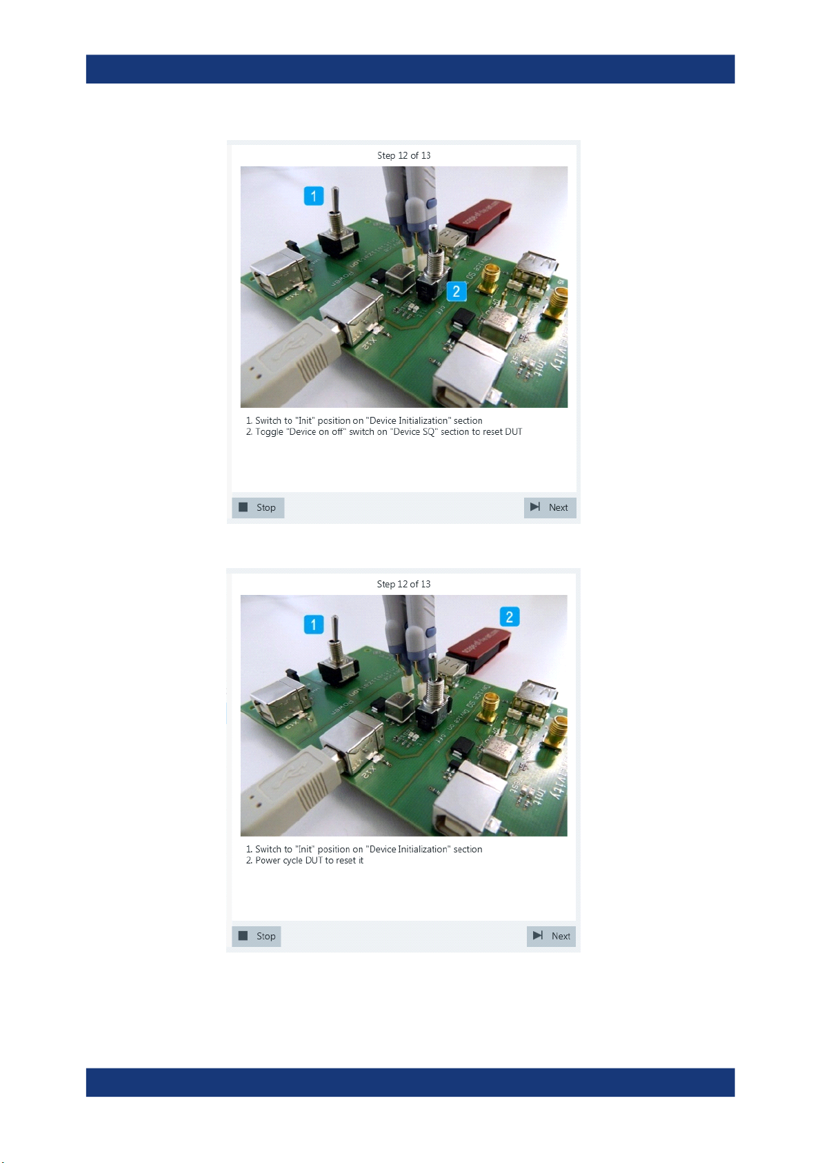
14. Switch the "Device Initialization" switch to the "Init" position and reset the DUT.
If the DUT is bus-powered, simply toggle the "Device on off" switch.
67User Manual 1317.4455.02 ─ 12
Page 68
R&S®RTO-K21, R&S®RTO6-K21, R&S®RTP-K21/-K101
Device Tests
USB2.0
If the DUT is self-powered, switch it off and switch it back on.
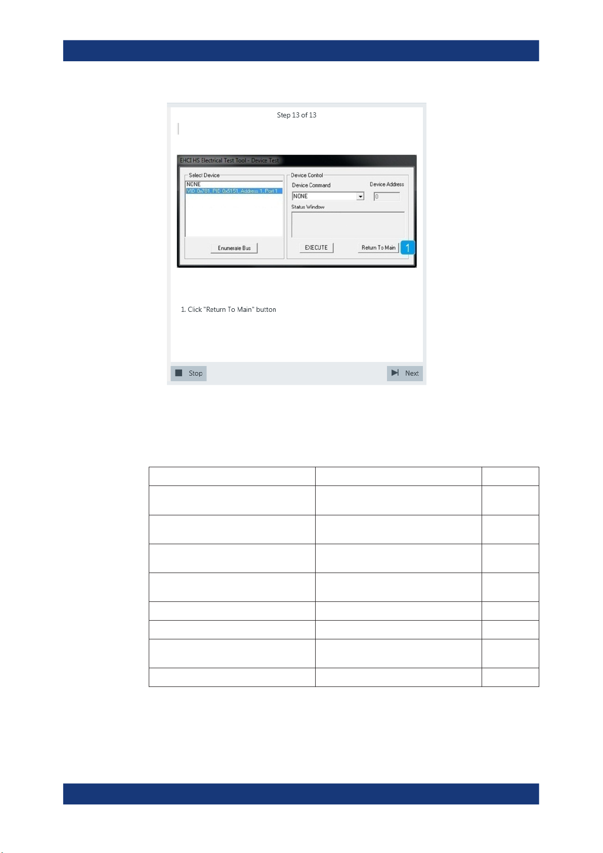
15. Proceed in the HS Electrical Test Tool as shown in the picture.
68User Manual 1317.4455.02 ─ 12
Page 69
R&S®RTO-K21, R&S®RTO6-K21, R&S®RTP-K21/-K101
Device Tests
USB2.0
The results are saved and can be viewed in the report.
4.1.1.6 Receiver Sensitivity
Table 4-6: Equipment
Item Description, model Quantity
Rohde & Schwarz oscilloscope R&S RTO/RTO6/RTP with 4 channels and
Signal quality board, "Reveiver Sensitivity"
section
Dual channel arbitrary waveform generator
(AWG)
SMA cable to connect the signal generator to the test
50 Ω SMA terminators to terminate unused outputs of the AWG 2
Differential probe at least 2 GHz bandwidth 1
Host test bed computer any computer with high-speed USB ports
USB cable to connect computer and test fixture 1
1
at least 2 GHz bandwidth
R&S RT‑ZF1 1
e.g. Tabor WX2182B/Tabor WX2182C 1
2
fixture
1
and HS Electrical Test Tool
Test preparation
Test preparation comprises common preparation steps and the connection of the AWG.
69User Manual 1317.4455.02 ─ 12
Page 70
R&S®RTO-K21, R&S®RTO6-K21, R&S®RTP-K21/-K101
Before you run the test, complete the following actions:
●
Initial setup of the equipment, see Chapter 2.2, "Installing Software and License",
on page 8
●
LAN connection of the oscilloscope and the computer running the R&S ScopeSuite, see Chapter 2.5, "Connecting the R&S RTO/RTO6/RTP", on page 10
●
Configure and initiate the test with DUT type = "Device", see Chapter 3.3, "Initiat-
ing the Test", on page 23
Additional preparation step:
●
LAN connection of the AWG and the computer running the R&S ScopeSuite, see
Chapter 2.6, "Connecting the Arbitrary Waveform Generator", on page 12.
●
Make sure that all unsued outputs of the AWG waveform generator are terminated
with a 50 Ω SMA terminators.
To execute the receiver sensitivity test in manual mode, the AWG has to output waveforms that simulate the IN token. These waveforms are described in Chapter 4.1.1.7,
"Setup of Test Waveforms", on page 79.
Running the test
Device Tests
USB2.0
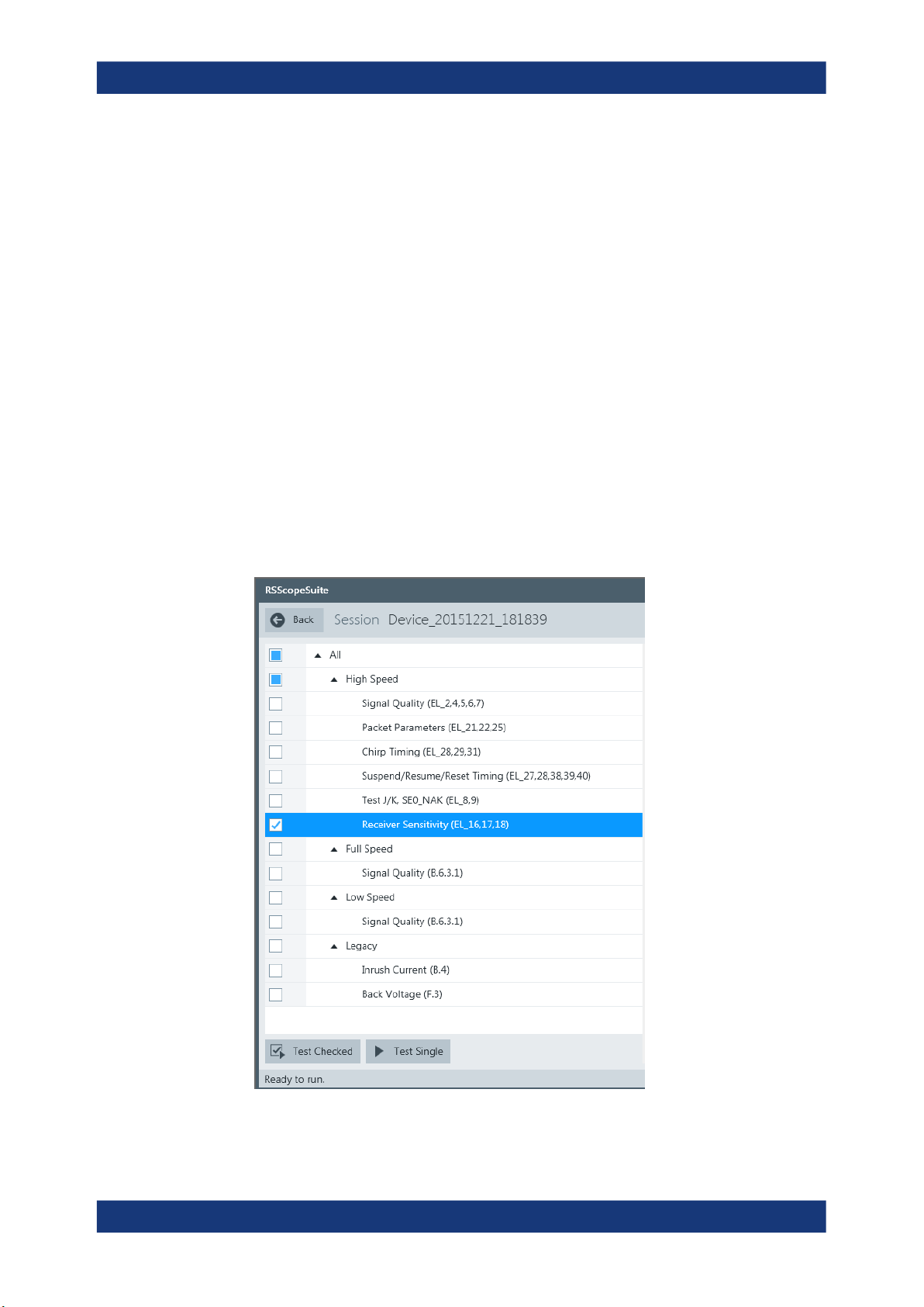
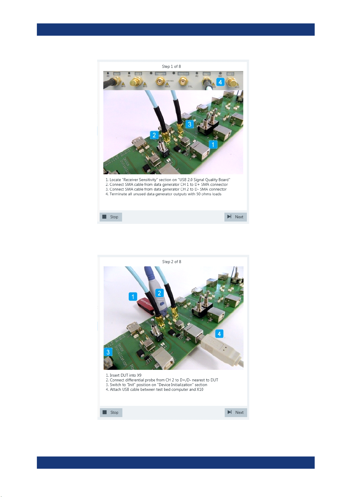
1. Select the "Receiver Sensitivity (EL_16,17,18)" test case and click "Test Single".
2. Connect the Tabor generator to the test fixture as shown in the picture.
70User Manual 1317.4455.02 ─ 12
Page 71
R&S®RTO-K21, R&S®RTO6-K21, R&S®RTP-K21/-K101
Device Tests
USB2.0
Click "Next".
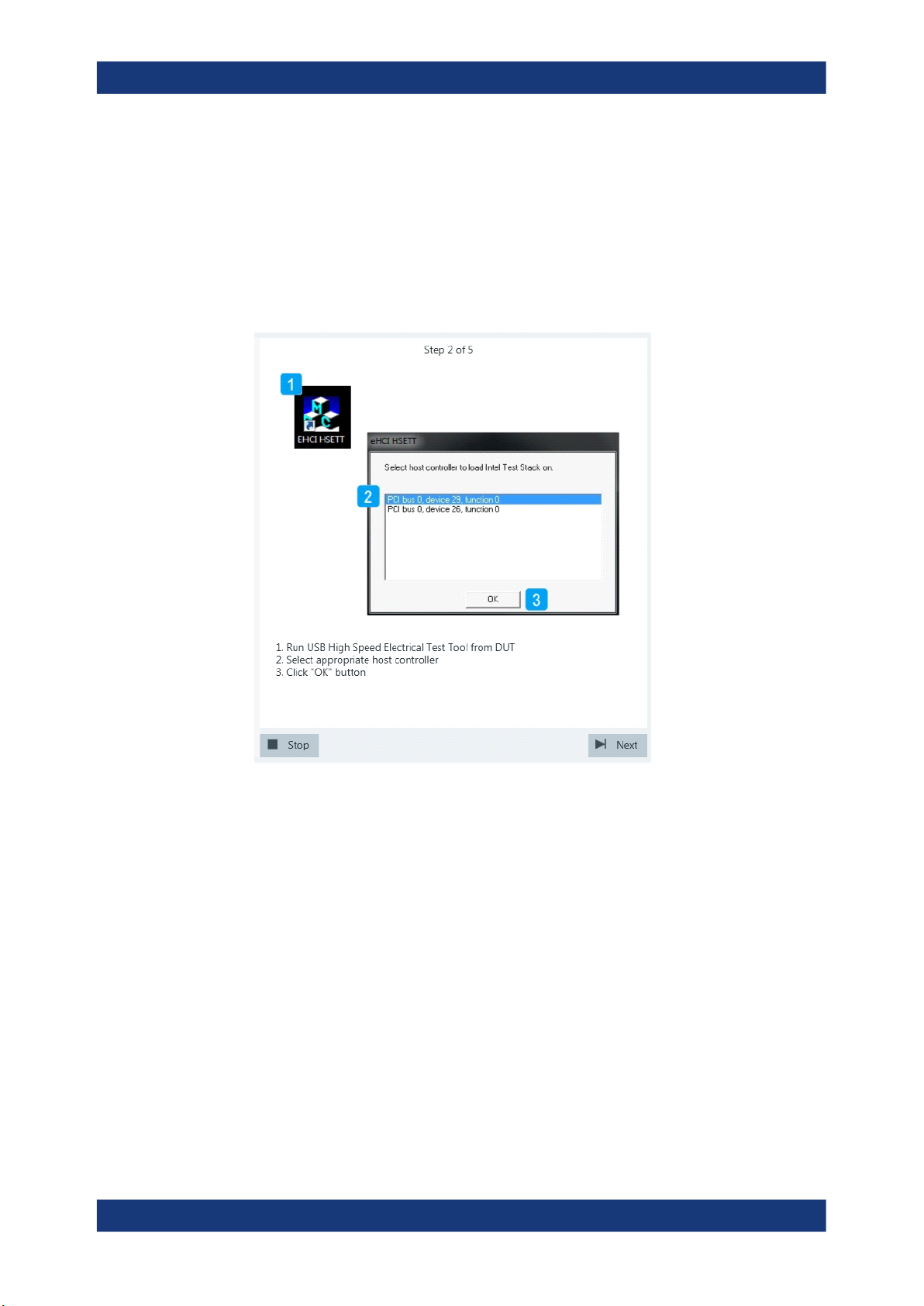
3. Connect the DUT to the test fixture as shown in the picture and click "Next".
71User Manual 1317.4455.02 ─ 12
Page 72
R&S®RTO-K21, R&S®RTO6-K21, R&S®RTP-K21/-K101
If the DUT has a type A connector attached, plug it into the test fixture directly. Otherwise, connect the DUT to the test fixture using a 4-inch cable.
Use a 1-meter non-captive cable to connect the test bed computer to the test fixture.
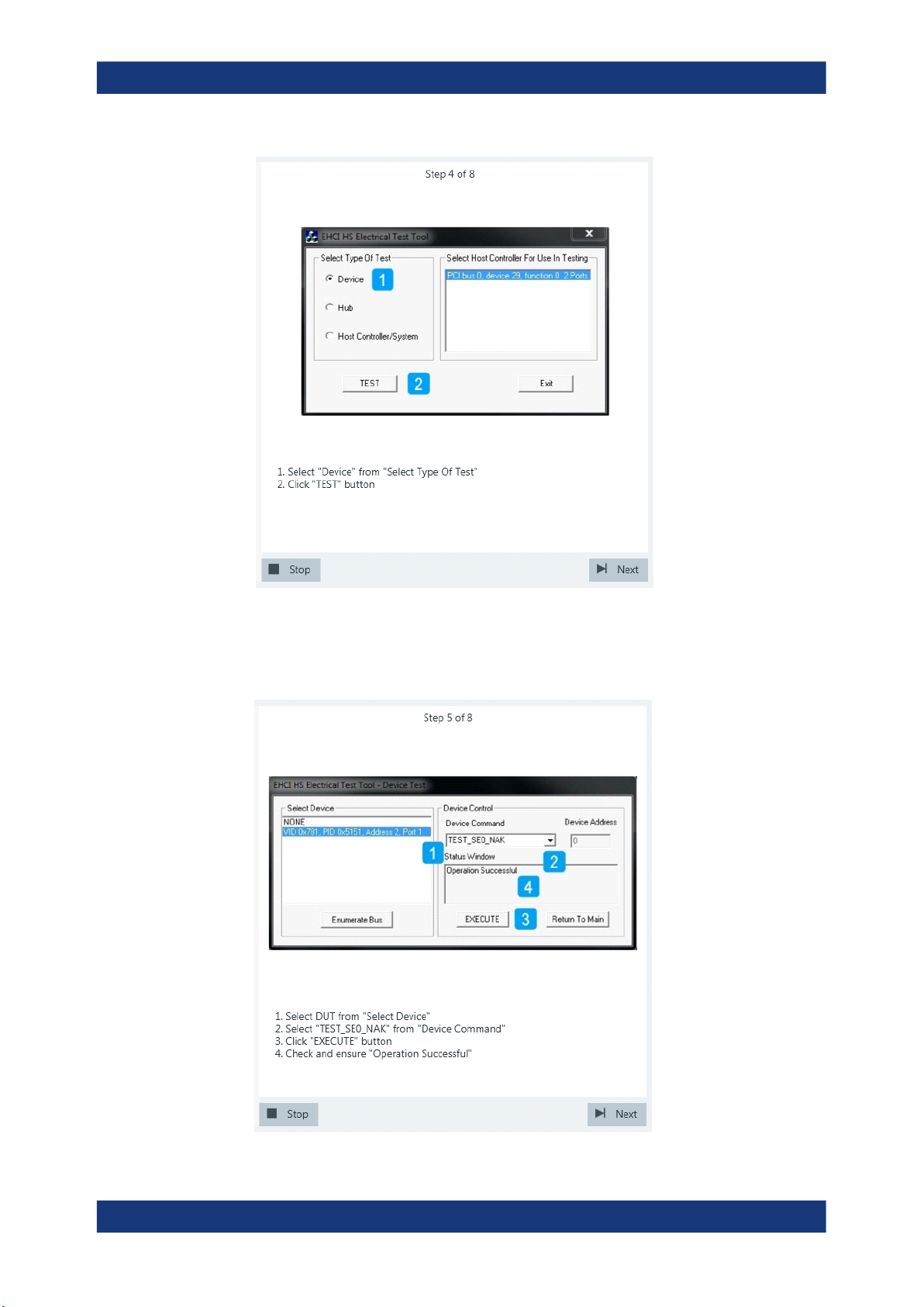
4. Start the HS Electrical Test Tool on the test bed computer.
5. Select the host controller to which the DUT is connected and click OK.
Note: the values in the list may vary.
Device Tests
USB2.0
6. Select "Device" on the left side.
Note: the values in the list may vary.
Click "TEST".
72User Manual 1317.4455.02 ─ 12
Page 73
R&S®RTO-K21, R&S®RTO6-K21, R&S®RTP-K21/-K101
Device Tests
USB2.0
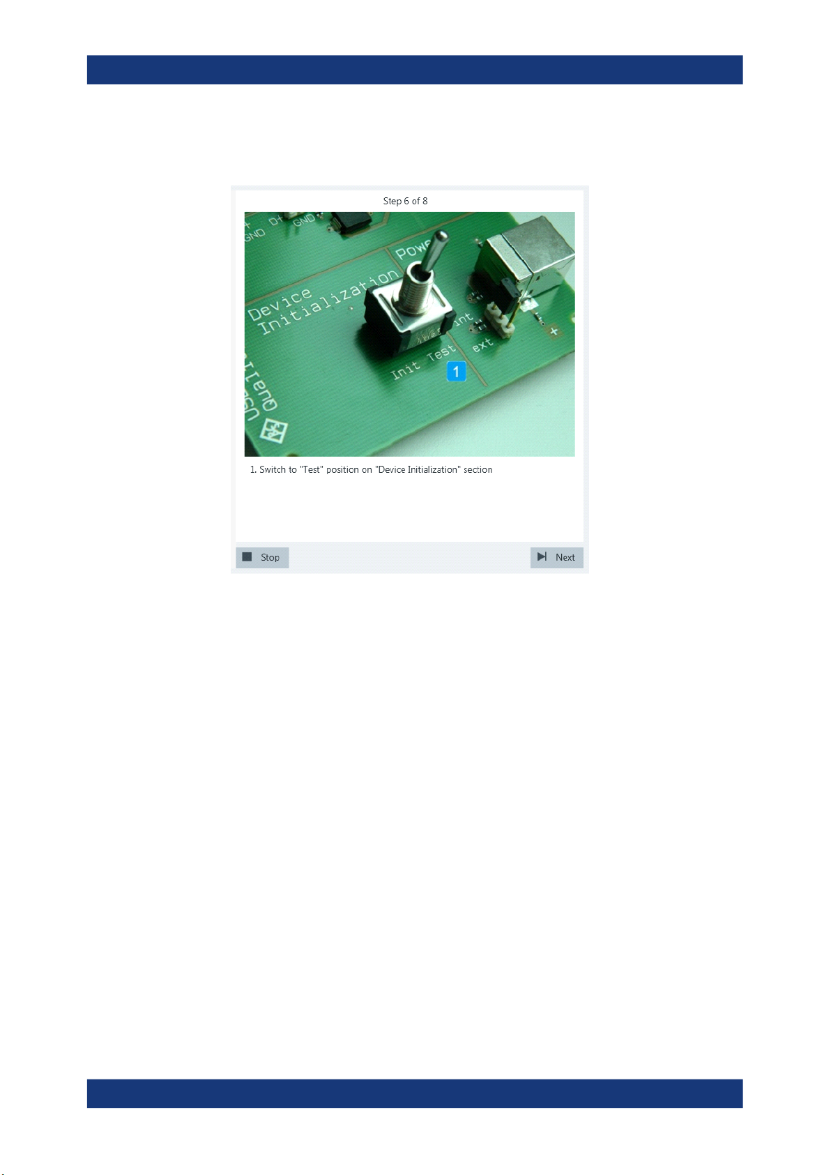
7. Select DUT from "Select Device"
Select "Test_SE0_NAK" from "Device Command".
Click "EXECUTE" and wait until "Operation Successful" is shown in "Status Window".
73User Manual 1317.4455.02 ─ 12
Page 74
R&S®RTO-K21, R&S®RTO6-K21, R&S®RTP-K21/-K101
8. Switch to "Test" position on "Device Initalization" section. Now the device (nega-
tive) acknowledges all signals send by the Tabor generator.
Device Tests
USB2.0
9. The application loads the “MIN_ADD1” waveform onto the Tabor generator.
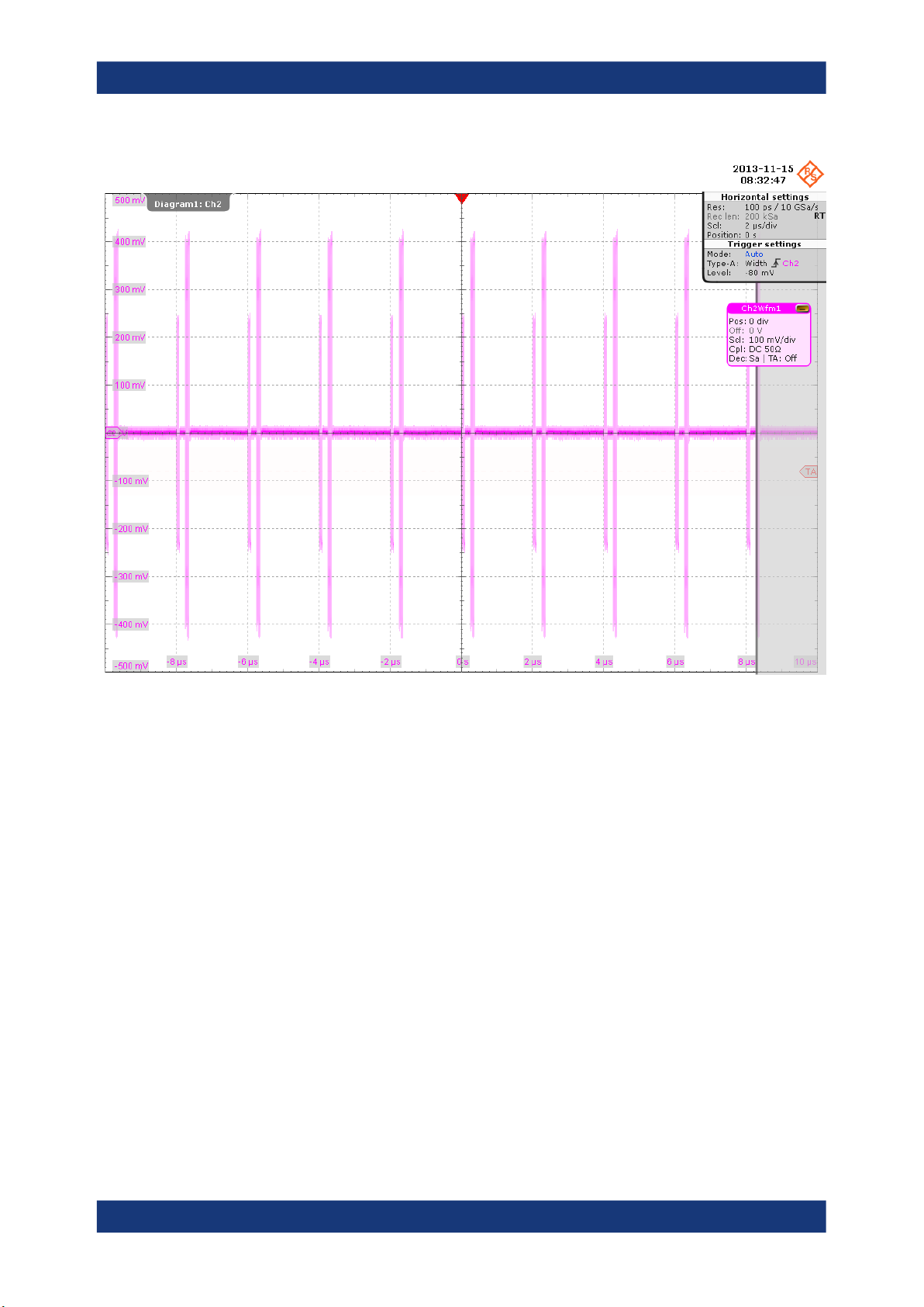
A waveform like this is captured.
74User Manual 1317.4455.02 ─ 12
Page 75
R&S®RTO-K21, R&S®RTO6-K21, R&S®RTP-K21/-K101
Device Tests
USB2.0
The bigger peak is the (negative) acknowledgement of the device and the smaller
peak is the packet sent by the Tabor generator.
The application verifies that all packets from the Tabor generator are (negative)
acknowledged. This is EL_18.
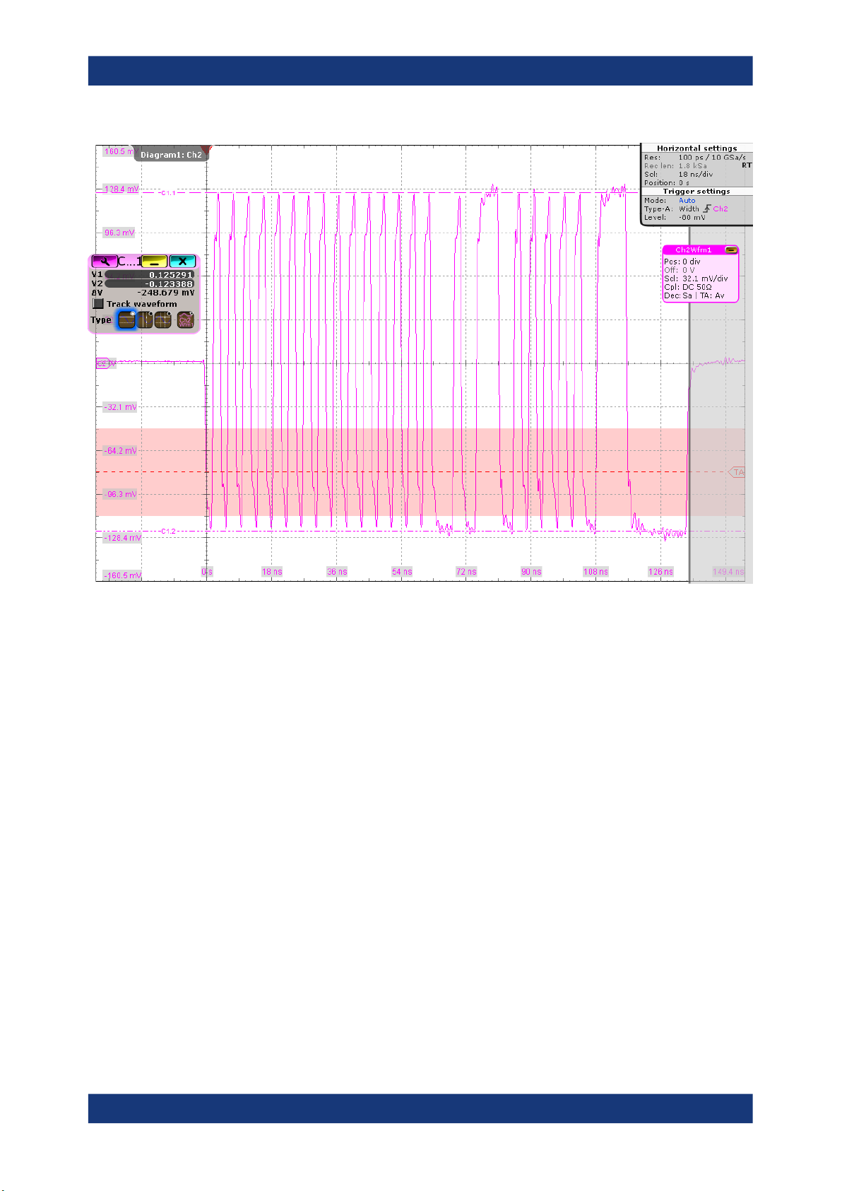
10. The application loads the “IN_ADD1” waveform onto the Tabor generator.
The waveform looks like this:
75User Manual 1317.4455.02 ─ 12
Page 76
R&S®RTO-K21, R&S®RTO6-K21, R&S®RTP-K21/-K101
Device Tests
USB2.0
The application decreases the output voltages of the Tabor generator in a step size
of 50 mV until the (negative) acknowledgement packets begin to become intermittent.
The application then increases the output voltages of the Tabor generator in a step
size of 5 mV until all packets from the Tabor generator are (negative) acknowledged again. The application measures the D+ and D- voltages of the packet from
the Tabor generator. The reading is taken at the plateaus of the wider pulses to
avoid inflated reading due to overshoots. This is EL_17.
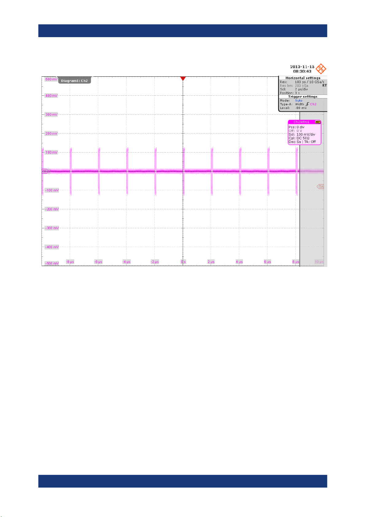
11. The application decreases the output voltages of the Tabor generator in a step size
of 5 mV until there is no more (negative) acknowledgement packet like this:
76User Manual 1317.4455.02 ─ 12
Page 77
R&S®RTO-K21, R&S®RTO6-K21, R&S®RTP-K21/-K101
Device Tests
USB2.0
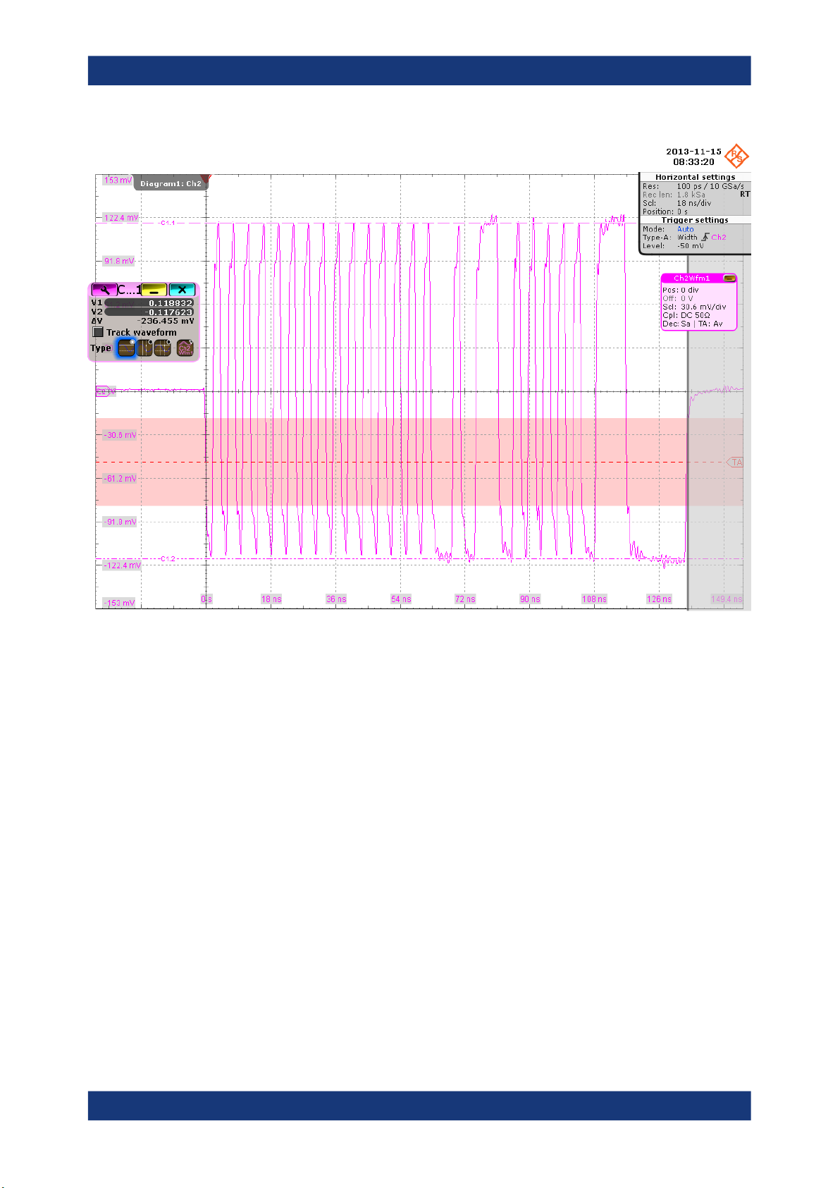
The application measures the D+ and D- voltages of the packet from the Tabor
generator. The reading is taken at the plateaus of the wider pulses to avoid inflated
reading due to overshoots. This is EL_16.
77User Manual 1317.4455.02 ─ 12
Page 78
R&S®RTO-K21, R&S®RTO6-K21, R&S®RTP-K21/-K101
Device Tests
USB2.0
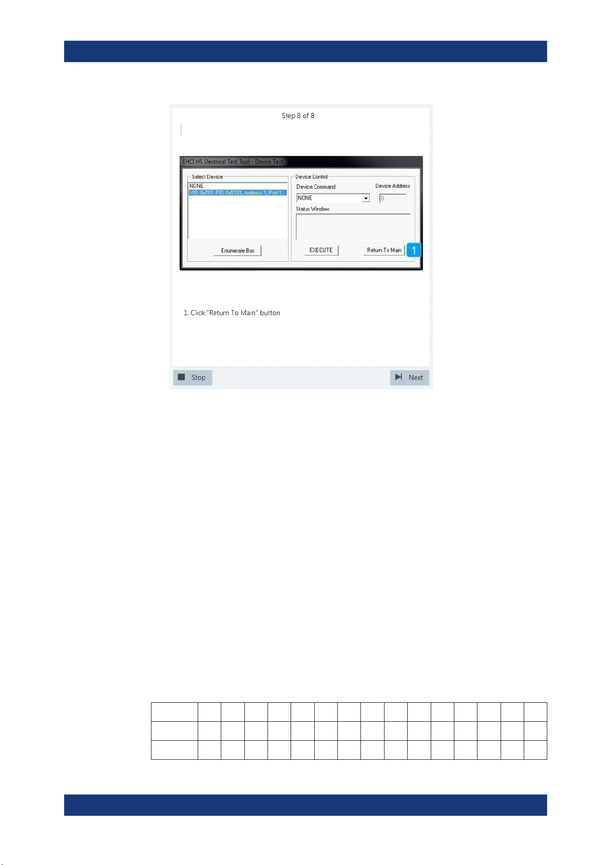
12. In the HS Electrical Test Tool, click “Return to Main”.
78User Manual 1317.4455.02 ─ 12
Page 79
R&S®RTO-K21, R&S®RTO6-K21, R&S®RTP-K21/-K101
Device Tests
USB2.0
The results are saved and can be viewed in the report.
4.1.1.7 Setup of Test Waveforms
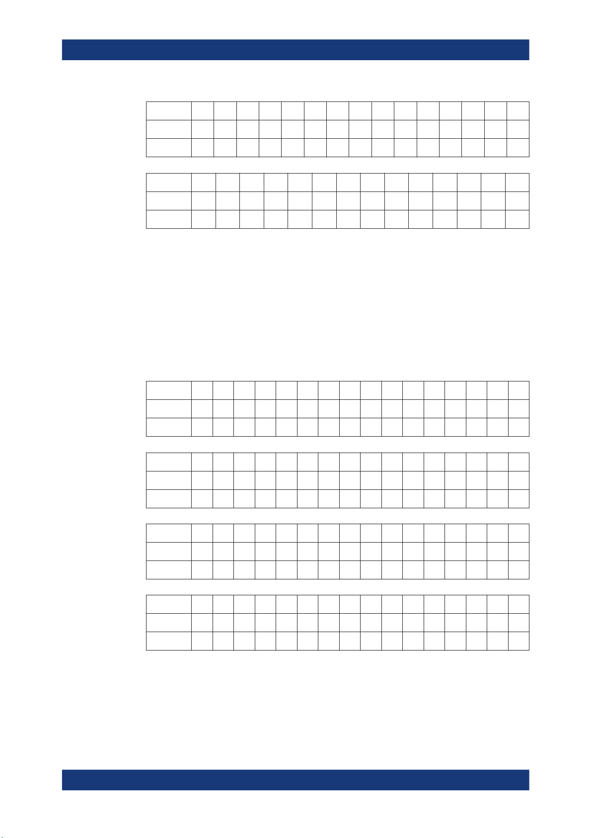
This section describes the characteristics of the required waveforms used for device or
hub receiver sensitivity testing. For these tests, a Tabor WX2182B/Tabor WX2182C 2.3
GS/s dual channel arbitrary waveform generator or similar can be used. If you use the
Tabor generator, you can create the waveforms using the Waveform Composer with
the files MIN_ADD1.txt and IN_ADD1.txt. The files are provided in the installation
directory of the R&S ScopeSuite.
MIN_ADD1
●
IN token of nominal bit rate and amplitude with shortest allowable sync field (12
bits)
●
Bit rate: 480 Mb/s
●
High level (both channels): 350 mV
●
Low level (both channels): 0 mV
●
Pattern length: 44 bits
●
Repetition rate: 2 μs (both channels should be at 0 mV for 916 bits following the
pattern)
Table 4-7: Pattern bits of MIN_ADD1
CH1 (D+) 0 1 0 1 0 1 0 1 0 1 0 0 0 1 0
CH2 (D-) 1 0 1 0 1 0 1 0 1 0 1 1 1 0 1
1 2 3 4 5 6 7 8 9 10 11 12 13 14 15
79User Manual 1317.4455.02 ─ 12
Page 80
R&S®RTO-K21, R&S®RTO6-K21, R&S®RTP-K21/-K101
Device Tests
USB2.0
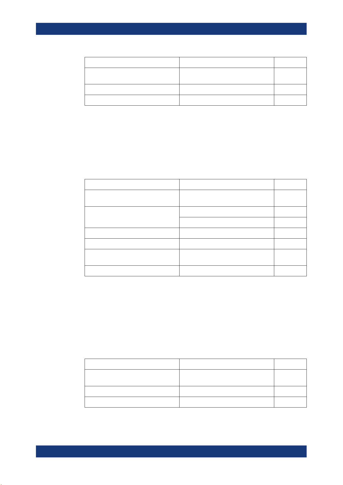
CH1 (D+) 0 1 1 1 0 0 1 0 1 0 1 0 1 0 1
CH2 (D-) 1 0 0 0 1 1 0 1 0 1 0 1 0 1 0
CH1 (D+) 0 0 1 1 1 1 0 0 0 0 0 0 0 0
CH2 (D-) 1 1 0 0 0 0 1 1 1 1 1 1 1 1
16 17 18 19 20 21 22 23 24 25 26 27 28 29 30
31 32 33 34 35 36 37 38 39 40 41 42 43 44
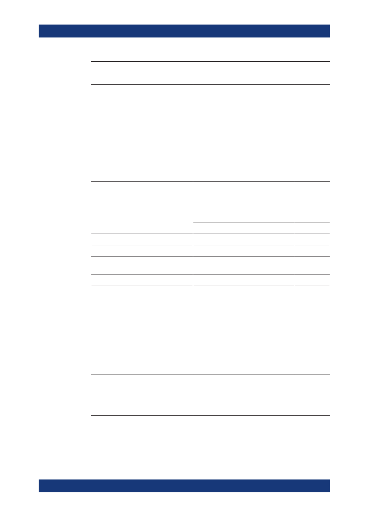
IN_ADD1
●
IN token of nominal bit rate, amplitude and sync field (32 bits)
●
Bit rate: 480 Mb/s
●
High level (both channels): 350 mV
●
Low level (both channels): 0 mV
●
Pattern length: 64 bits
●
Repetition rate: 2 μs (both channels should be at 0 mV for 896 bits following the
pattern)
Table 4-8: Pattern bits of IN_ADD1
1 2 3 4 5 6 7 8 9 10 11 12 13 14 15 16
CH1 (D+) 0 1 0 1 0 1 0 1 0 1 0 1 0 1 0 1
CH2 (D-) 1 0 1 0 1 0 1 0 1 0 1 0 1 0 1 0
CH1 (D+) 0 1 0 1 0 1 0 1 0 1 0 1 0 1 0 0
CH2 (D-) 1 0 1 0 1 0 1 0 1 0 1 0 1 0 1 1
CH1 (D+) 0 1 0 1 0 1 0 1 0 1 0 1 0 1 0 1
CH2 (D-) 1 0 1 0 1 0 1 0 1 0 1 0 1 0 1 0
CH1 (D+) 0 1 0 1 0 1 0 1 0 1 0 1 0 1 0 0
CH2 (D-) 1 0 1 0 1 0 1 0 1 0 1 0 1 0 1 1
17 18 19 20 21 22 23 24 25 26 27 28 29 30 31 32
33 34 35 36 37 38 39 40 41 42 43 44 45 46 47 48
49 50 51 52 53 54 55 56 57 58 59 60 61 62 63 64
80User Manual 1317.4455.02 ─ 12
Page 81

R&S®RTO-K21, R&S®RTO6-K21, R&S®RTP-K21/-K101
4.1.2 Full Speed, Low Speed and Legacy Device Tests
In addition to the high-speed tests described in the preceeding chapter, the device
under test must also pass a set of full speed and low speed compliance tests applicable to high-speed devices. The documentation of these legacy tests can be found in
the "USB-IF Full and Low Speed Compliance Test Procedure" manual issued by the
USB-IF. The manual is available at http://www.usb.org/developers.
To perform full speed and low speed compliance tests, you can use also a 4-channel
R&S RTO/RTO6/RTP with less than 2 GHz bandwidth.
4.2 USB 3.2
USB 3.2 compliance tests require option R&S RTP-K101.
The USB 3.2 comliance tests, test the limits as defined in the "Electrical Compliance
Test Specification Enhanced SuperSpeed Universal Serial Bus, Rev1" specification.
Device Tests
USB 3.2
4.2.1 Measurement Setups
When performing USB 3.2 device compliance tests, you can use one of the following
setups:
● Gen 1 Device Type-A Test Setup............................................................................81
● Gen 2 Device Type-A Test Setup............................................................................82
● Gen 2 Captive Cable Device Type-A Test Setup.................................................... 82
● Gen 2 Device Type-C Test Setup............................................................................83
● Gen 2 Captive Cable Device Type-C Test Setup.................................................... 83
● Device Tests with R&S RT-ZB2...............................................................................84
4.2.1.1 Gen 1 Device Type-A Test Setup
Required settings:
●
"Test Fixture for USB 3.2" = "USB-IF"
●
"Connector source"="Standard-A"
The required equipment is listed in the following table.
Table 4-9: Gen 1 device Type-A tests equipment
Item Description, model Quantity
Rohde & Schwarz oscilloscope R&S RTP with 4 channels and at least
1
16 GHz bandwidth
USB3ET device test fixtures Device test fixture 1 1
Device test fixture 2 1
DUT The device you want to test 1
Adapters R&S RTP-ZA16 adapter 2
81User Manual 1317.4455.02 ─ 12
Page 82
R&S®RTO-K21, R&S®RTO6-K21, R&S®RTP-K21/-K101
Item Description, model Quantity
Device Tests
USB 3.2
A pair of matched SMA cables if USB-IF
host test fixture is used
Short A-B or A-uB Cable To connect the DUT and the test fixture 1
USB type A-B cable To connect the two test fixtures 1
4.2.1.2 Gen 2 Device Type-A Test Setup
Required settings:
●
"Test Fixture for USB 3.2" = "USB-IF"
●
"Connector source"="Standard-A"
The required equipment is listed in the following table.
Table 4-10: Gen 2 device Type-A tests equipment
Item Description, model Quantity
Rohde & Schwarz oscilloscope R&S RTP with 4 channels and at least
USB31AET device test fixtures Device test fixture 1A 1
DUT The device you want to test 1
- 1
1
16 GHz bandwidth
5.6 " CLB test fixture 1
Adapters R&S RTP-ZA16 adapter 2
A pair of matched SMA cables if USB-IF
host test fixture is used
USB type A-uB Cable To connect the two test fixtures 1
- 1
4.2.1.3 Gen 2 Captive Cable Device Type-A Test Setup
Required settings:
●
"Test Fixture for USB 3.2" = "USB-IF"
●
"Connector source"="Standard-A"
●
"Captive Cable" = "Enabled"
The required equipment is listed in the following table.
Table 4-11: Gen 2 device captive cable Type-A test equipment
Item Description, model Quantity
Rohde & Schwarz oscilloscope R&S RTP with 4 channels and at least
16 GHz bandwidth
USB31AET device test fixtures Captive cable device fixture type-A 1
DUT The captive cable device you want to test 1
1
82User Manual 1317.4455.02 ─ 12
Page 83
R&S®RTO-K21, R&S®RTO6-K21, R&S®RTP-K21/-K101
Item Description, model Quantity
Adapters R&S RTP-ZA16 adapter 2
Device Tests
USB 3.2
A pair of matched SMA cables if USB-IF
host test fixture is used
4.2.1.4 Gen 2 Device Type-C Test Setup
Required settings:
●
"Test Fixture for USB 3.2" = "USB-IF"
●
"Connector source"="Type-C"
The required equipment is listed in the following table.
Table 4-12: Gen 2 device Type-C tests equipment
Item Description, model Quantity
Rohde & Schwarz oscilloscope R&S RTP with 4 channels and at least
USB31CET device test fixtures Device test fixture 1C 1
DUT The device you want to test 1
Adapters R&S RTP-ZA16 adapter 2
A pair of matched SMA cables if USB-IF
host test fixture is used
- 1
1
16 GHz bandwidth
5.6 " CLB test fixture 1
- 1
USB type C Cable To connect the two test fixtures 1
4.2.1.5 Gen 2 Captive Cable Device Type-C Test Setup
Required settings:
●
"Test Fixture for USB 3.2" = "USB-IF"
●
"Connector source" = "Type- C"
●
"Captive Cable" = "Enabled"
The required equipment is listed in the following table.
Table 4-13: Gen 2 device captive cable Type-C test equipment
Item Description, model Quantity
Rohde & Schwarz oscilloscope R&S RTP with 4 channels and at least
16 GHz bandwidth
USB31CET device test fixtures Captive cable device fixture type C 1
DUT The captive cable device you want to test 1
1
83User Manual 1317.4455.02 ─ 12
Page 84
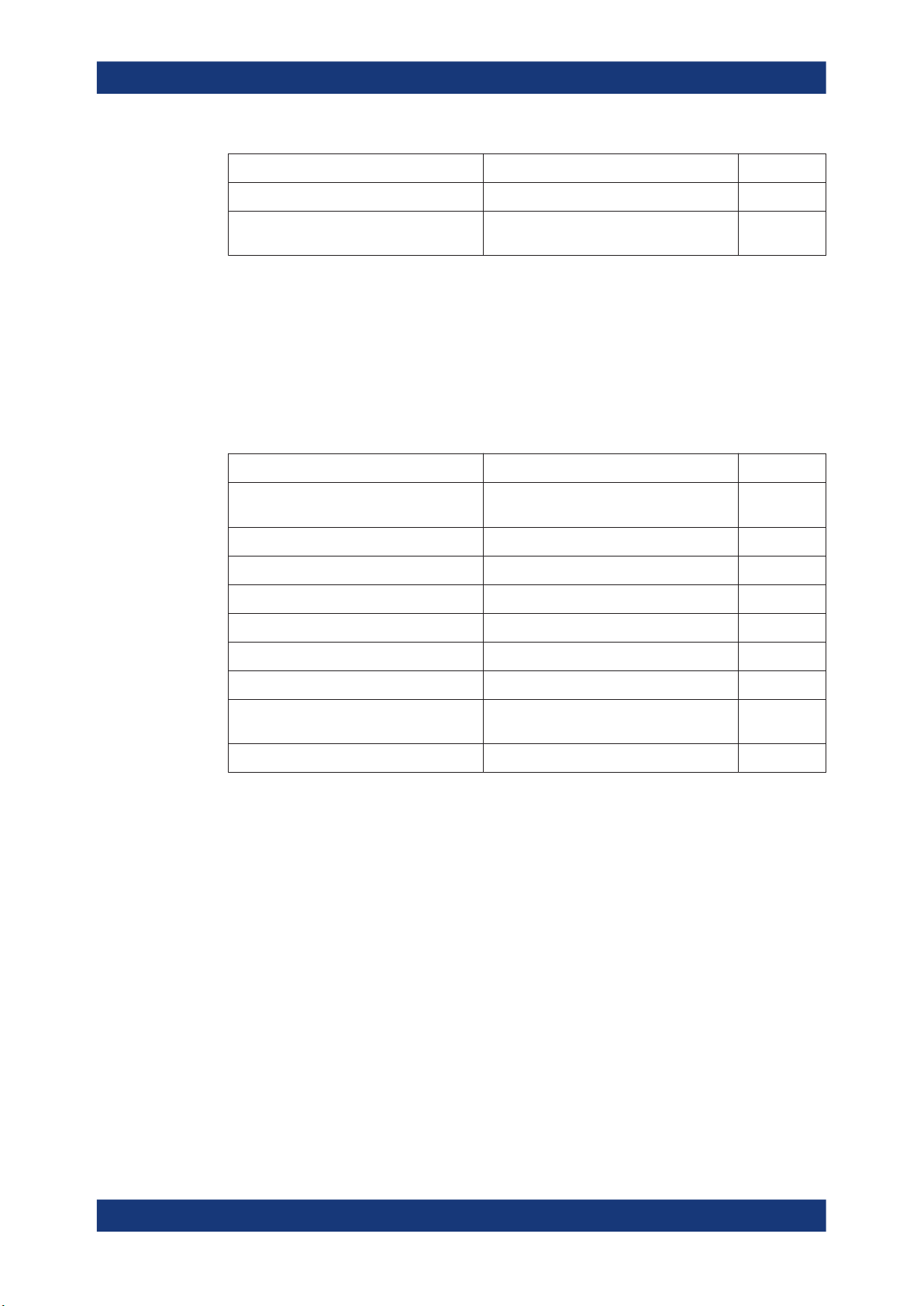
R&S®RTO-K21, R&S®RTO6-K21, R&S®RTP-K21/-K101
Item Description, model Quantity
Adapters R&S RTP-ZA16 adapter 2
Device Tests
USB 3.2
A pair of matched SMA cables if USB-IF
host test fixture is used
4.2.1.6 Device Tests with R&S RT-ZB2
Required settings:
●
"Test Fixture for USB 3.2" = "Rohde & Schwarz"
●
"Connector source" = "Standard-A"
The required equipment is listed in the following table.
Table 4-14: Device Type-A tests equipment
Item Description, model Quantity
Rohde & Schwarz oscilloscope R&S RTP with 4 channels and at least
Test fixture R&S RT-ZB2 1
DUT The device you want to test 1
Adapters R&S RTP-ZA16 adapter 2
A pair of matched SMA cables - 1
BNC- SMA adapters - 1
- 1
1
16 GHz bandwidth
USB cable To connect the fixture and the oscilloscope 1
Waveform generator (optional) R&S RTP-B6/Tabor WX2182B/Tabor
WX2182C
DUT The device you want to test 1
4.2.2 Gen1 (5GT/s) Low Frequency Periodic Signaling Tx
This test verifies that the low frequency periodic signal transmitter meets the timing
requirements as defined in the specification.
Test preparation
Before you run the test, complete the following actions:
●
Initial setup of the equipment, see Chapter 2.2, "Installing Software and License",
on page 8
●
LAN connection of the oscilloscope and the computer running the R&S ScopeSuite, see Chapter 2.5, "Connecting the R&S RTO/RTO6/RTP", on page 10
●
Configure and initiate the test with DUT type = "Device", see Chapter 3.3, "Initiat-
ing the Test", on page 23
For an overview of the needed equipment, see Chapter 4.2.1, "Measurement Setups",
on page 81.
1
84User Manual 1317.4455.02 ─ 12
Page 85
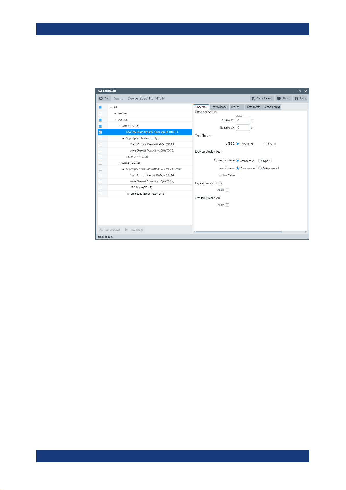
R&S®RTO-K21, R&S®RTO6-K21, R&S®RTP-K21/-K101
Running the test
1. Select the "Gen1 (5GT/s) Low Frequency Periodic Signaling Tx (TD.1.1 )" test
case.
Device Tests
USB 3.2
2. Click "Test Single".
3. Follow the instructions of the step-by step guide.
When you have finished all steps, the compliance test runs automatically.
The results are saved and can be viewed in the report.
Further steps:
●
Chapter 3.4, "Getting Test Results", on page 23
4.2.3 Gen1 (5GT/s) SuperSpeed Transmitted Eye
This test verifies that the transmitter meets the eye width, deterministic jitter and random jitter requirements for the test conditions described in the specification for long
and for short channel reference equalizer.
Test preparation
For an overview of the needed equipment, see Chapter 4.2.1, "Measurement Setups",
on page 81.
Before you run the test, complete the following actions:
●
Initial setup of the equipment, see Chapter 2.2, "Installing Software and License",
on page 8
85User Manual 1317.4455.02 ─ 12
Page 86
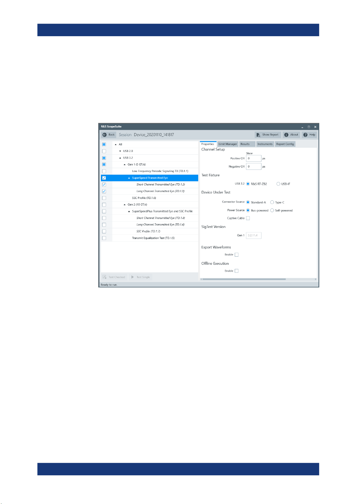
R&S®RTO-K21, R&S®RTO6-K21, R&S®RTP-K21/-K101
●
LAN connection of the oscilloscope and the computer running the R&S ScopeSuite, see Chapter 2.5, "Connecting the R&S RTO/RTO6/RTP", on page 10
●
Configure and initiate the test with DUT type = "Device", see Chapter 3.3, "Initiat-
ing the Test", on page 23
Running the test
1. Select the "Gen1 (5G/Ts) SuperSpeed Transmitted Eye" test case.
Device Tests
USB 3.2
2. Click "Test Single".
3. Follow the instructions of the step-by step guide.
When you have finished all steps, the compliance test runs automatically.
The results are saved and can be viewed in the report.
Further steps:
●
Chapter 3.4, "Getting Test Results", on page 23
4.2.4 Gen1 (5GT/s) SSC Profile
The test verifies that the transmitter meets SSC profile requirements, for measurements at the compliance test port with spec required TX equalization as defined in the
specification.
86User Manual 1317.4455.02 ─ 12
Page 87
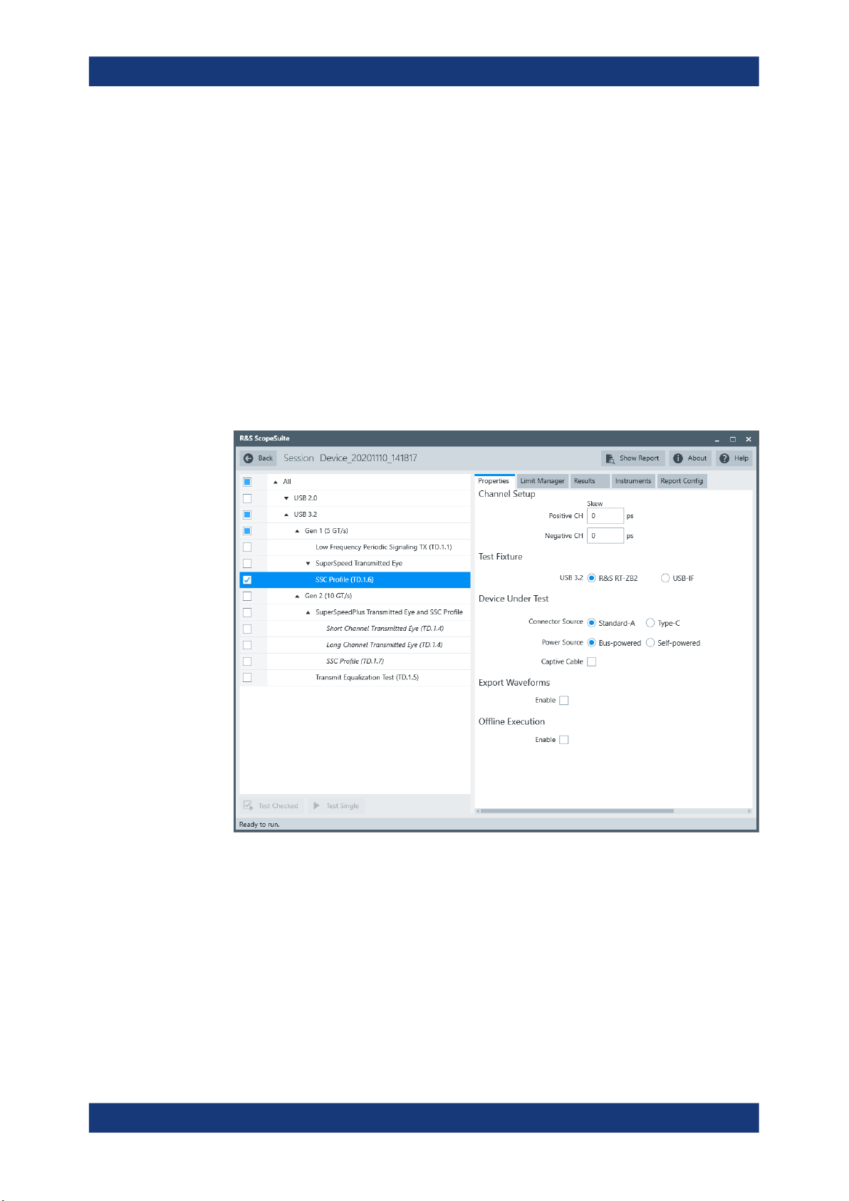
R&S®RTO-K21, R&S®RTO6-K21, R&S®RTP-K21/-K101
Test preparation
For an overview of the needed equipment, see Chapter 4.2.1, "Measurement Setups",
on page 81.
Before you run the test, complete the following actions:
●
Initial setup of the equipment, see Chapter 2.2, "Installing Software and License",
on page 8
●
LAN connection of the oscilloscope and the computer running the R&S ScopeSuite, see Chapter 2.5, "Connecting the R&S RTO/RTO6/RTP", on page 10
●
Configure and initiate the test with DUT type = "Device", see Chapter 3.3, "Initiat-
ing the Test", on page 23
Running the test
1. Select the "Gen1 (5GT/s) SSC Profile (TD.1.6 )" test case.
Device Tests
USB 3.2
2. Click "Test Single".
3. Follow the instructions of the step-by step guide.
When you have finished all steps, the compliance test runs automatically.
The results are saved and can be viewed in the report.
Further steps:
●
Chapter 3.4, "Getting Test Results", on page 23
87User Manual 1317.4455.02 ─ 12
Page 88
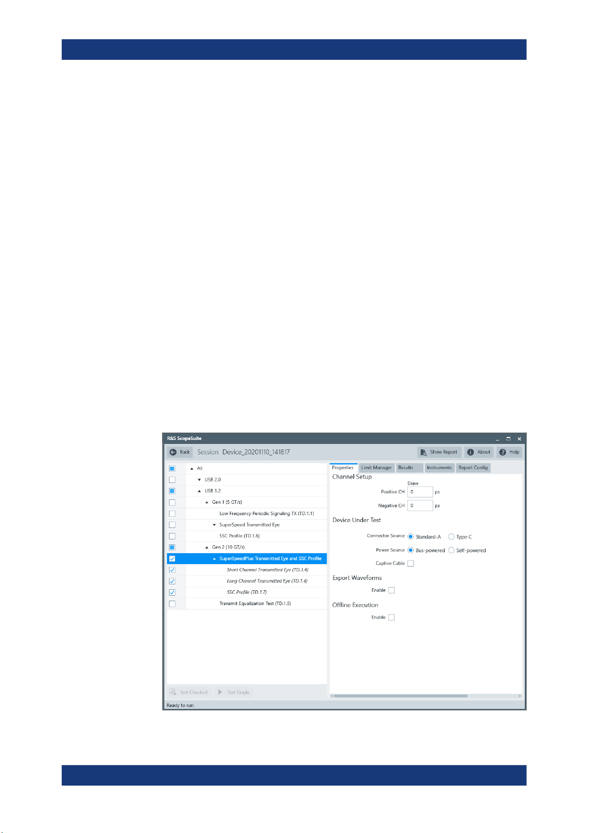
R&S®RTO-K21, R&S®RTO6-K21, R&S®RTP-K21/-K101
4.2.5 Gen2 (10GT/s) SuperSpeedPlus Transmitted Eye and SSC Profile
This test verifies that the transmitter meets the eye width, eye height, deterministic jitter
and random jitter requirements for the test conditions described in the specification for
short and long channel reference equalizer.
The "SSC Profile" test verifies that the transmitter meets SSC profile requirements, for
measurements at the compliance test port with spec required TX equalization as
defined in the specification.
Test preparation
For an overview of the needed equipment, see Chapter 4.2.1, "Measurement Setups",
on page 81.
Before you run the test, complete the following actions:
●
Initial setup of the equipment, see Chapter 2.2, "Installing Software and License",
on page 8
●
LAN connection of the oscilloscope and the computer running the R&S ScopeSuite, see Chapter 2.5, "Connecting the R&S RTO/RTO6/RTP", on page 10
●
Configure and initiate the test with DUT type = "Device", see Chapter 3.3, "Initiat-
ing the Test", on page 23
Device Tests
USB 3.2
Running the test
1. Select the "Gen2 (10GT/s) SuperSpeedPlus Transmitted Eye and SSC Profile "
test case.
88User Manual 1317.4455.02 ─ 12
Page 89

R&S®RTO-K21, R&S®RTO6-K21, R&S®RTP-K21/-K101
2. Click "Test Single".
3. Follow the instructions of the step-by step guide.
When you have finished all steps, the compliance test runs automatically.
The results are saved and can be viewed in the report.
Further steps:
●
Chapter 3.4, "Getting Test Results", on page 23
4.2.6 Gen2 (10GT/s) Transmit Equalization Test
This test verifies that the transmitter meets requirements for transmit equalization as
defined in the specification.
Test preparation
For an overview of the needed equipment, see Chapter 4.2.1, "Measurement Setups",
on page 81.
Device Tests
USB 3.2
Before you run the test, complete the following actions:
●
Initial setup of the equipment, see Chapter 2.2, "Installing Software and License",
on page 8
●
LAN connection of the oscilloscope and the computer running the R&S ScopeSuite, see Chapter 2.5, "Connecting the R&S RTO/RTO6/RTP", on page 10
●
Configure and initiate the test with DUT type = "Device", see Chapter 3.3, "Initiat-
ing the Test", on page 23
Running the test
1. Select the "Gen2 (10GT/s) Transmit Equalization Test (TD.1.5)" test case.
89User Manual 1317.4455.02 ─ 12
Page 90
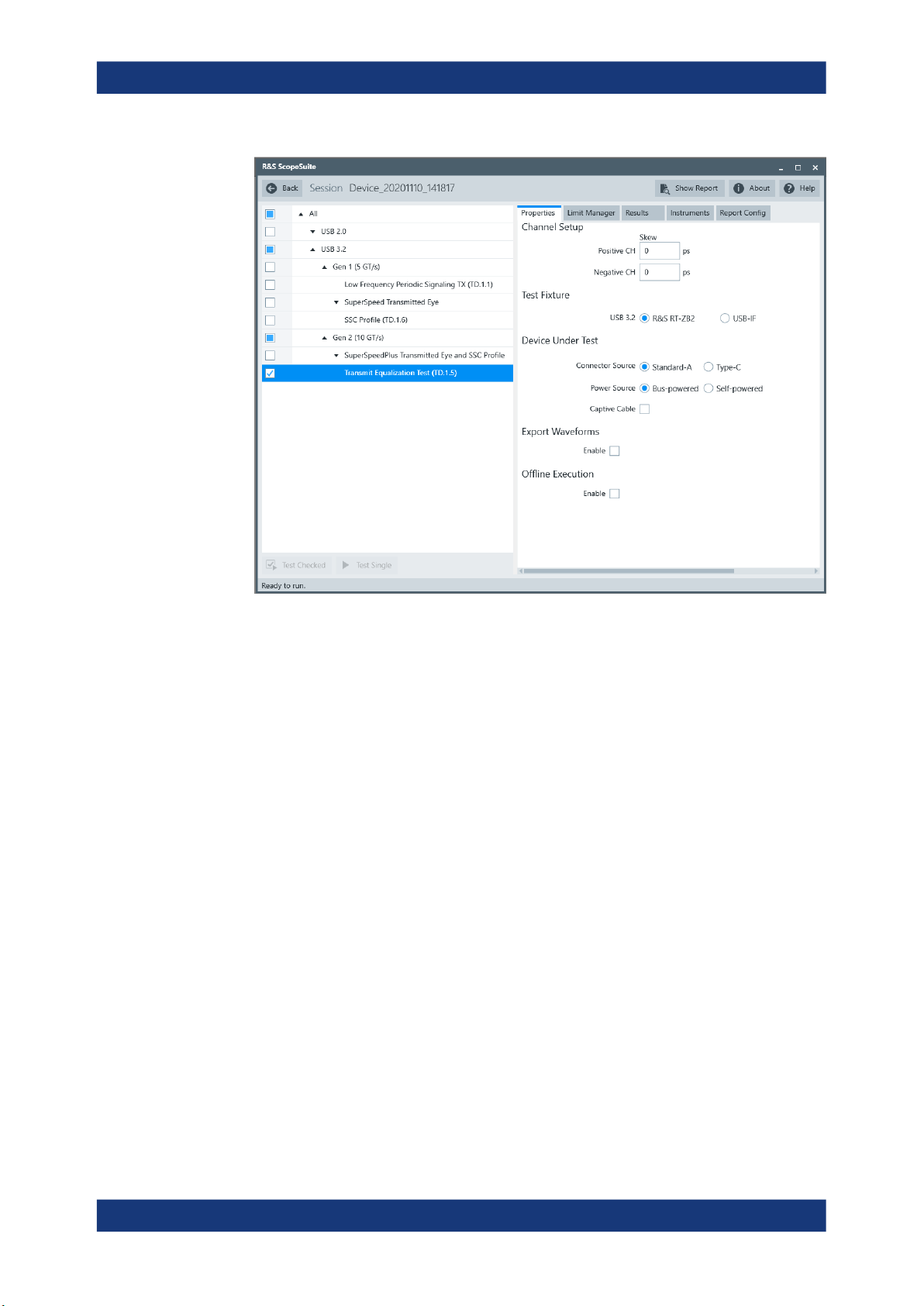
R&S®RTO-K21, R&S®RTO6-K21, R&S®RTP-K21/-K101
Device Tests
USB 3.2
2. Click "Test Single".
3. Follow the instructions of the step-by step guide.
When you have finished all steps, the compliance test runs automatically.
The results are saved and can be viewed in the report.
Further steps:
●
Chapter 3.4, "Getting Test Results", on page 23
90User Manual 1317.4455.02 ─ 12
Page 91
R&S®RTO-K21, R&S®RTO6-K21, R&S®RTP-K21/-K101
5 Hub Tests
5.1 USB 2.0
5.1.1 High-Speed Hub Tests
● Upstream Signal Quality......................................................................................... 91
● Downstream Signal Quality.....................................................................................92
● Downstream Jitter................................................................................................... 98
● Upstream Packet Parameters...............................................................................104
● Upstream Receiver Sensitivity.............................................................................. 105
● Upstream Repeater...............................................................................................106
● Downstream Repeater.......................................................................................... 113
● Upstream Chirp Timing..........................................................................................117
● Upstream Suspend/Resume/Reset Timing........................................................... 118
● Upstream Test J/K, SE0_NAK............................................................................... 119
● Downstream Test J/K, SE0_NAK.......................................................................... 119
Hub Tests
USB 2.0
5.1.1.1 Upstream Signal Quality
Table 5-1: Equipment
Item Description, model Quantity
Rohde & Schwarz oscilloscope R&S RTO/RTO6/RTP with 4 channels and
DUT the hub you want to test 1
Signal quality board, "Device SQ" section or
USB-IF USB2.0 hi-speed signal quality
device test fixture
Differential probe or a pair of matched SMA
cables if USB-IF device test fixture is used
Host test bed computer any computer with high-speed USB ports
USB cable to connect computer and test fixture 1
Test preparation
Before you run the test, complete the following actions:
●
Initial setup of the equipment, see Chapter 2.2, "Installing Software and License",
on page 8
●
LAN connection of the oscilloscope and the computer running the R&S ScopeSuite, see Chapter 2.5, "Connecting the R&S RTO/RTO6/RTP", on page 10
at least 2 GHz bandwidth
R&S RT‑ZF1 1
differential probe with at least 2 GHz bandwidth
and HS Electrical Test Tool
1
1
1
91User Manual 1317.4455.02 ─ 12
Page 92
R&S®RTO-K21, R&S®RTO6-K21, R&S®RTP-K21/-K101
●
Configure and initiate the test with DUT type = "Hub", see Chapter 3.3, "Initiating
the Test", on page 23
Running the test
The upstream signal quality test for hubs is mainly the same as the signal quality test
for devices. Follow the instructions in the R&S ScopeSuite, and refer to the test
description in Chapter 4.1.1.1, "Signal Quality", on page 25 Make sure to select "Hub"
in the "HS Electrical Test Tool" (step 5).
5.1.1.2 Downstream Signal Quality
Table 5-2: Equipment
Item Description, model Quantity
Hub Tests
USB 2.0
Rohde & Schwarz oscilloscope R&S RTO/RTO6/RTP with 4 channels and
at least 2 GHz bandwidth
DUT the hub you want to test 1
Signal quality board, "Host Signal Quality"
section, or USB-IF USB2.0 hi-speed signal
quality host test fixture
Differential probe or a pair of matched SMA
cables if USB-IF host test fixture is used
Host test bed computer any computer with high-speed USB ports
USB cable to connect computer and test fixture 1
R&S RT‑ZF1 1
differential probe with at least at least 2 GHz
bandwidth
and HS Electrical Test Tool
Test preparation
Before you run the test, complete the following actions:
●
Initial setup of the equipment, see Chapter 2.2, "Installing Software and License",
on page 8
●
LAN connection of the oscilloscope and the computer running the R&S ScopeSuite, see Chapter 2.5, "Connecting the R&S RTO/RTO6/RTP", on page 10
●
Configure and initiate the test with DUT type = "Hub", see Chapter 3.3, "Initiating
the Test", on page 23
1
1
1
Running the test
1. Select the "Downstream Signal Quality (EL_2,3,6,7)" test case and click "Test Sin-
gle".
92User Manual 1317.4455.02 ─ 12
Page 93
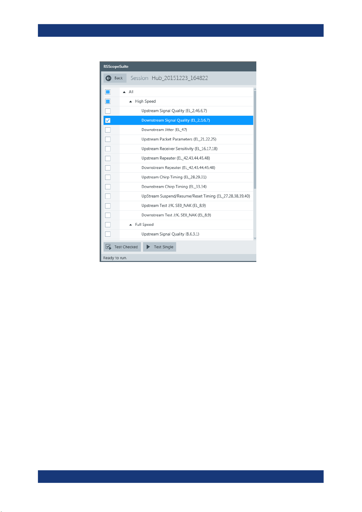
R&S®RTO-K21, R&S®RTO6-K21, R&S®RTP-K21/-K101
Hub Tests
USB 2.0
2. Connect the DUT to the test fixture as shown in the picture.
93User Manual 1317.4455.02 ─ 12
Page 94
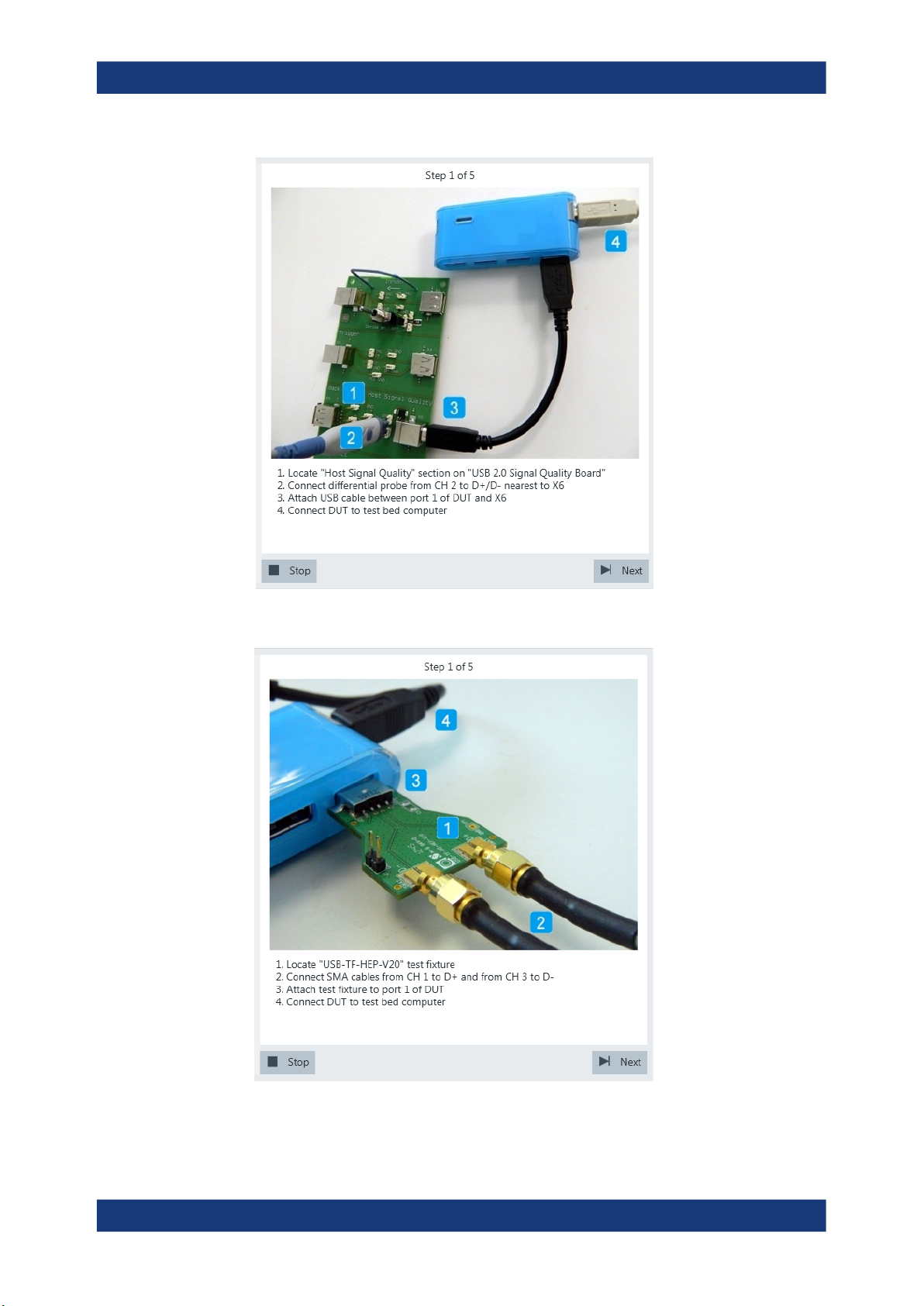
R&S®RTO-K21, R&S®RTO6-K21, R&S®RTP-K21/-K101
Hub Tests
USB 2.0
Figure 5-1: R&S RT‑ZF1: connection to DUT
Figure 5-2: USB-IF USB2.0 Hi-Speed Signal Quality host test fixture: connection to DUT
94User Manual 1317.4455.02 ─ 12
Page 95
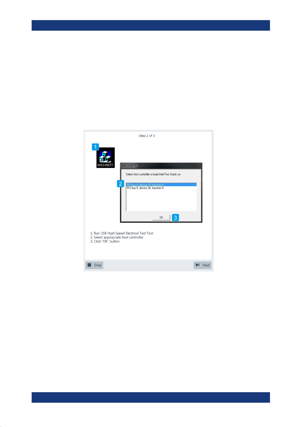
R&S®RTO-K21, R&S®RTO6-K21, R&S®RTP-K21/-K101
If R&S test fixture is used, connect the test fixture to the downstream port under
test with a 4-inch non-captive cable. If USB-IF test fixture is used, connect the test
fixture directly to the downstream port under test.
If the DUT has a cable attached, plug it into the test bed computer directly. Otherwise, use a 1-meter cable to connect the test bed computer to the upstream port.
Click "Next".
3. Start the HS Electrical Test Tool on the test bed computer.
4. Select the host controller to which the DUT is connected and click OK.
Note: the values in the list may vary.
Click "Next" in the R&S ScopeSuite.
Hub Tests
USB 2.0
5. Select "Hub" on the left side, and click "TEST"
95User Manual 1317.4455.02 ─ 12
Page 96
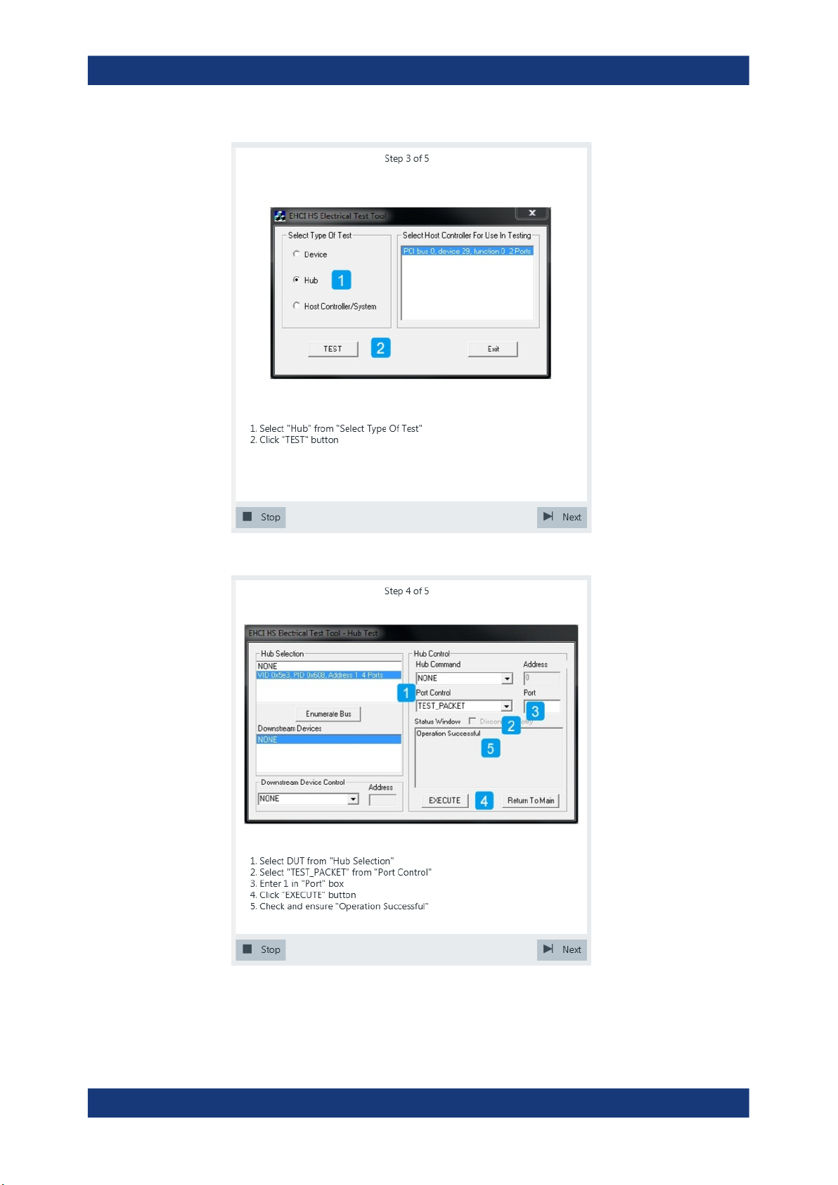
R&S®RTO-K21, R&S®RTO6-K21, R&S®RTP-K21/-K101
Hub Tests
USB 2.0
6. Configure the HS Electrical Test Tool as shown in the picture.
The test packets are sent to the oscilloscope. They are analyzed in an eye diagram.
96User Manual 1317.4455.02 ─ 12
Page 97
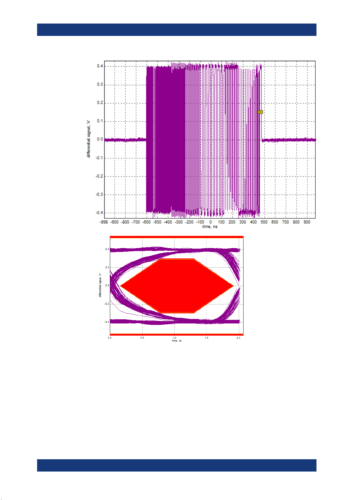
R&S®RTO-K21, R&S®RTO6-K21, R&S®RTP-K21/-K101
Hub Tests
USB 2.0
7. Proceed in the HS Electrical Test Tool as shown in the picture.
97User Manual 1317.4455.02 ─ 12
Page 98
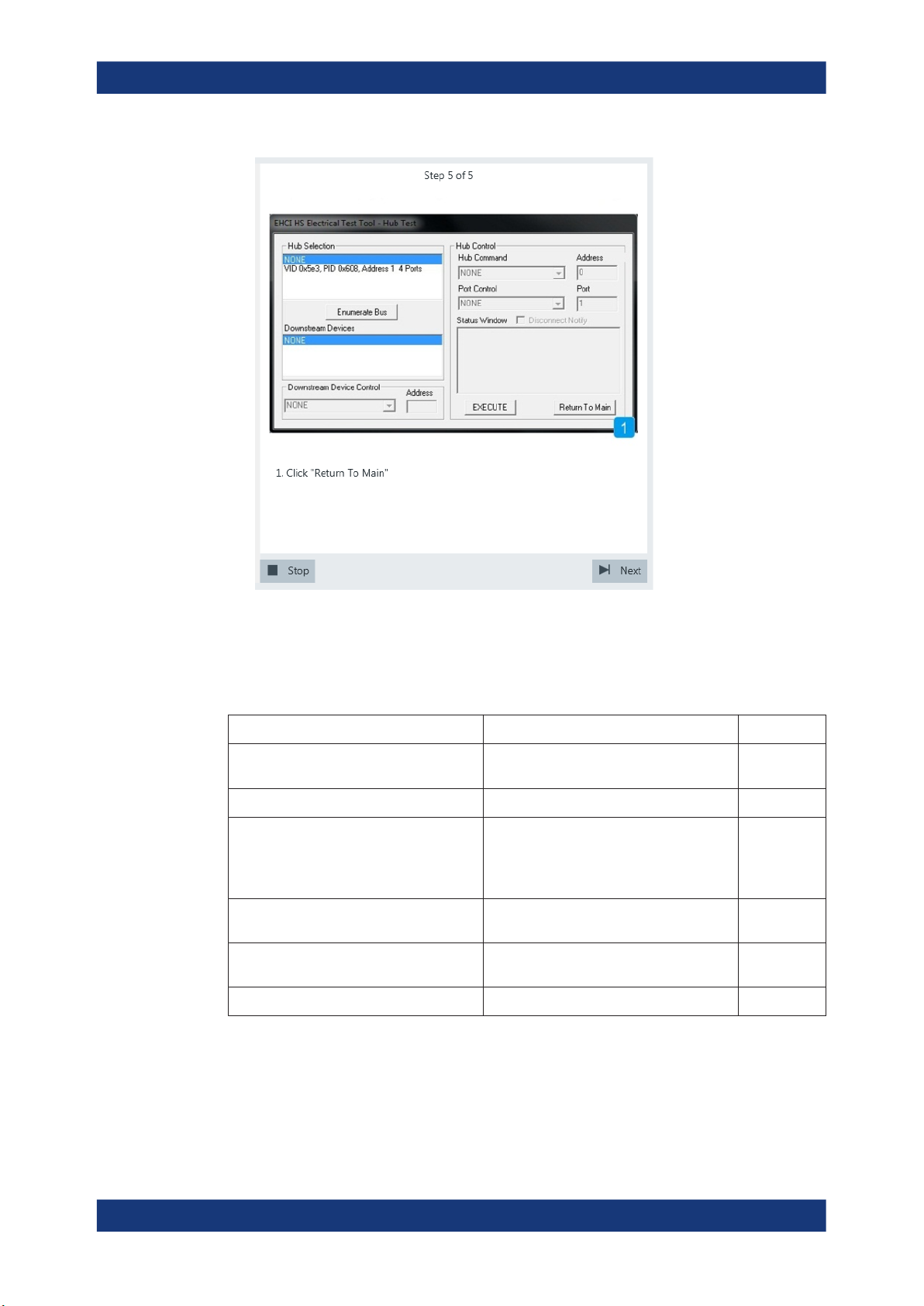
R&S®RTO-K21, R&S®RTO6-K21, R&S®RTP-K21/-K101
Hub Tests
USB 2.0
The results are saved and can be viewed in the report.
5.1.1.3 Downstream Jitter
Table 5-3: Equipment
Item Description, model Quantity
Rohde & Schwarz oscilloscope R&S RTO/RTO6/RTP with 4 channels and
DUT the hub you want to test 1
Signal quality board, "Host Signal Quality"
section,
or USB-IF USB2.0 hi-speed signal quality
host test fixture
Differential probe, or a pair of matched SMA
cables if USB-IF host test fixture is used
Host test bed computer any computer with high-speed USB ports
USB cable to connect computer and test fixture 1
Test preparation
at least 2 GHz bandwidth
R&S RT‑ZF1 1
Differential probe with at least 2 GHz bandwidth
and HS Electrical Test Tool
1
1
1
Before you run the test, complete the following actions:
●
Initial setup of the equipment, see Chapter 2.2, "Installing Software and License",
on page 8
98User Manual 1317.4455.02 ─ 12
Page 99
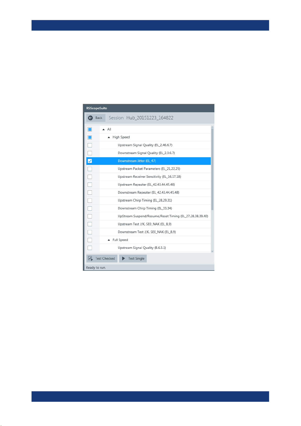
R&S®RTO-K21, R&S®RTO6-K21, R&S®RTP-K21/-K101
●
LAN connection of the oscilloscope and the computer running the R&S ScopeSuite, see Chapter 2.5, "Connecting the R&S RTO/RTO6/RTP", on page 10
●
Configure and initiate the test with DUT type = "Hub", see Chapter 3.3, "Initiating
the Test", on page 23
Running the test
1. Select the "Downstream Jitter (EL_47)" test case and click "Test Single".
Hub Tests
USB 2.0
2. Connect the DUT to the test fixture as shown in the picture.
99User Manual 1317.4455.02 ─ 12
Page 100
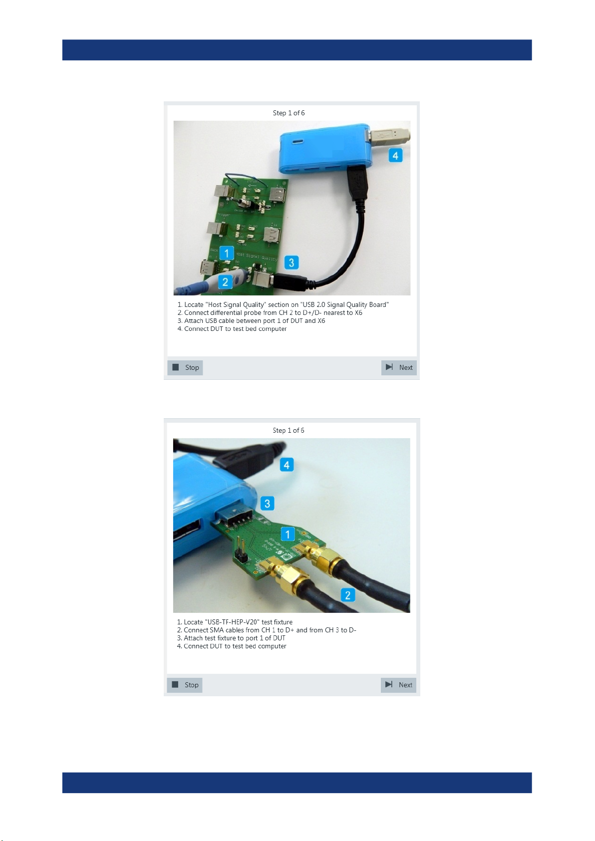
R&S®RTO-K21, R&S®RTO6-K21, R&S®RTP-K21/-K101
Hub Tests
USB 2.0
Figure 5-3: R&S RT‑ZF1: connection to DUT
Figure 5-4: USB-IF USB2.0 hi-speed signal quality host test fixture: connection to DUT
100User Manual 1317.4455.02 ─ 12
 Loading...