

Page 1
Manual
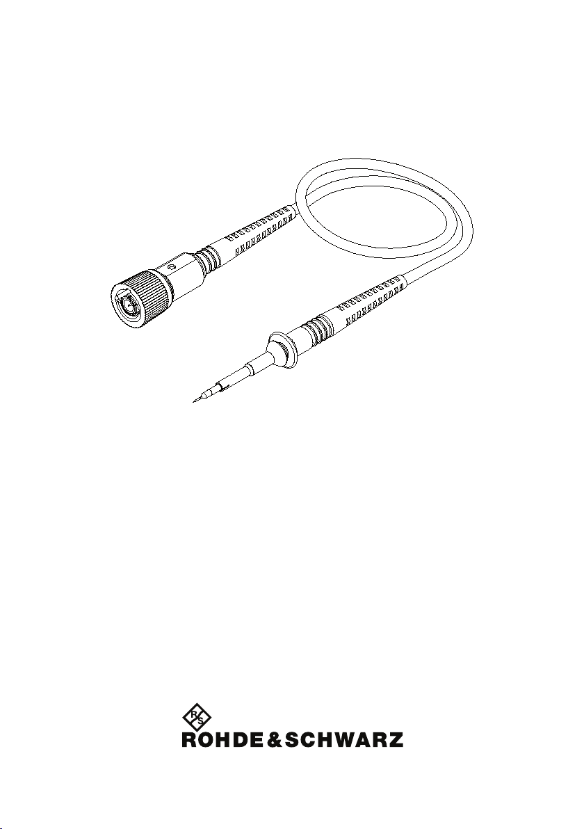
500 MHz Passive Voltage Probe
R&S
®
RT-ZP10
1409.7550.00
Printed in Germany
Test and Measurement
Page 2
2
Manufacturer R&S RT-ZP10
ROHDE & SCHWARZ
For comprehensive information about Rohde and Schwarz, please visit our homepage on the R&S Internet
(http://www.rohde-schwarz.com).
For queries regarding technical aspects of our products, please contact our customer support at
http://www.customersupport.rohde-schwarz.com.
For international services, please contact our service partners at http://www.service.rohde-schwarz.com.
For additional questions, please contact our headquarters in Munich.
ROHDE & SCHWARZ GmbH & Co. KG
Mühldorfstraße 15
D-81671 München
Phone: +49 (89) 41 29 - 0
Fax: +49 (89) 41 29 - 12 164
Declaration of Conformity
(EC conformity marking)
The manufacturer declares the conformity of this product with the actual required safety standards in
accordance with the Low Voltage Directive (LVD) 73/23/EEC and amendment 93/68/EEC:
CEI/IEC 61010-031:2002 Safety requirements for electrical equipment
for measurement, control and laboratory use -
Part 031:
Safety requirements for hand-held probe
assemblies for electrical measurement and test
WEEE/ RoHS Directives
(EC conformity marking)
This electronic product is classified within the WEEE/ RoHS* category list as monitoring and control
equipment (category 9). Category 9 products are exempted from the restrictions under the scope of the
RoHS directive.
Your help and efforts are required to protect and keep clean our environment. Therefore return this
electronic product at the end of its life either to the manufacturer or take care of separate WEEE
collection and professional WEEE treatment yourself. Do not dispose as unsorted municipal waste!
* EC Directives:
WEEE Directive 2002/96/EC - Waste Electrical and Electronic Equipment
RoHS Directive 2002/95/EC - Restriction of the use of certain Hazardous Substances
in Electrical and Electronic Equipment
Page 3

3
IEC Measurement Categories R&S RT-ZP10
Definitions and examples (Clause 6.5.2 )
Measurement Category I Definition: Measurement category I is for measurements performed
on circuits not directly connected to a mains supply.
Examples: Measurements in circuits not derived from a mains supply
and specially protected ( internal ) circuits derived
from a mains supply. In the latter case, transient stresses
are variable; for that reason requires that the transient
withstand capability of the equipment is made known to
the user.
Measurement Category II Definition: Measurement category II is for measurements performed
CAT II on circuits directly connected to the low voltage
installation.
Examples: Household appliances, portable tools and similar
equipment.
Measurement Category III Definition: Measurement category III is for measurements
CAT III performed in the building installation.
Examples: Measurements on distribution boards, circuit breakers,
wiring including cables, bus-bars, junction boxes, switches,
socket-outlets in the fixed installation and equipment for
industrial use like for example stationary motors with per manent connection to the fixed installation.
Measurement Category IV Definition: Measurement category IV is for measurements
CAT IV performed at the source of the low-voltage installation.
Examples: Electricity meters and measurements on primary over
current protection devices and and ripple control units.
IEC Pollution Degrees
Definitions (Clause 3.5.6 )
Pollution Degree 1 No POLLUTION or only dry, non conductive POLLUTION.
NOTE: The POLLUTION has no influence.
Pollution Degree 2 Only non-conductive POLLUTION. Occasionally, however, a temporary
conductivity caused by condensation must be accepted.
Pollution Degree 3 Conductive POLLUTION occurs or dry, non-conductive POLLUTION occurs
which becomes conductive due to condensation which is to be expected.
Page 4
4
IEC Safety Symbols R&S RT-ZP10
The following symbols may appear on the product or in this instruction manual:
Caution, risk of danger. Refer to manual.
Caution, risk of electric shock.
Earth (ground) TERMINAL.
Safety Information
To avoid personal injury and to prevent fire or damage to this product or products connected to it, review and
comply with the following safety precautions. Be aware that if you use this probe assembly in a manner not
specified the protection this product provides may be impaired.
Only qualified personnel should use this probe assembly.
Use only grounded instruments.
Do not connect the probe ground lead to a potential other than earth ground. Always make sure the probe and
the measurement instrument are grounded properly.
Connect and disconnect properly.
Connect the probe output to the measurement instrument and connect the ground lead to earth ground before
connecting the probe to the circuit under test. Disconnect the probe input and the probe ground lead from the
circuit under test before disconnecting the probe from the measurement instrument.
Observe probe ratings.
Do not apply any electrical potential to the probe input which exceeds the maximum ratings of the probe.
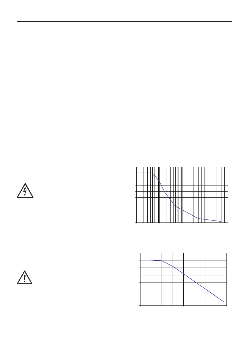
Make sure to comply with the voltage versus frequency derating curve on page 5.
Keep away from live circuits.
Avoid open circuitry. Do not touch connections or components when power is present.
Do not operate with suspected failures.
Refer to qualified service personnel.
Indoor use only.
Do not operate in wet/damp environment. Keep product surfaces dry and clean.
Do not operate the product in an explosive atmosphere.
Page 5
5
Specifications R&S RT-ZP10
Typical Voltage Derating RT-ZP10
Measurement Category I
0
100
200
300
400
100K 1M 10M 100M 1G
Frequency [Hz]
Amplitude AC root mean square [V]
Typical Input Imp edance RT-ZP10
10
100
1 k
10 k
100 k
1 M
10 M
10 100 1K 10K 100K 1M 10 M 100M 1G
Frequency [Hz]
|Z| [Ohm]
Specifications that are not defined to be guaranteed are typical and are published as general information to the
user. The instrument should have warmed-up for at least 20 minutes and the environmental conditions do not
exceed the probe's specified limits.
Electrical Specifications
Attenuation Ratio
Voltage Coefficient 0.0025 %/V (typical)
System Bandwidth
Probe Risetime
(1)
10:1 ± 2 % at DC
(1)
500 MHz (-3 dB)
(1)
700 ps (10 % - 90 %) (typical)
Input Resistance (System) 10 MΩ ± 1 %
Input Capacitance (System) 9.5 pF (typical)
Compensation Range 5 pF - 20 pF (typical)
Input Coupling of the Measuring Instrument 1 MΩ AC / DC
(2)
Maximum Rated Input Voltage
Measurement Category I: 400 V root mean square
1250 V transient overvoltage
Measurement Category II: 300 V root mean square CAT II
Pollution Degree
(2)
2
Voltage Derating
Note that the max. input voltage
rating of the probe decreases as
the frequency of the applied
signal increases.
Input Impedance
(1) Connected to appropriate R&S oscilloscope. See R&S oscilloscope operating manual for further details.
(2) As defined in IEC 61010-031. See definitions explained on page 3.
Note that the input impedance of
the probe decreases as the frequency
of the applied signal increases.
Page 6
6
Specifications R&S RT-ZP10
Mechanical Characteristics
Weight (Probe only) 48 g
Cable Length 1.3 m
Probe Tip Diameter 2.5 mm
Environmental Specifications
Altitude operating up to 2000 m
non-operating up to 15000 m
Temperature Range operating 0° C to +50° C
non-operating -40° C to +71° C
Maximum Relative Humidity operating 80 % relative humidity for temperatures up to +31° C,
decreasing linearly to 40 % at +50° C
Adjustment Procedures
The probe can be adjusted for low frequency (LF) compensation and for high frequency (HF) compensation.
LF Compensation
LF needs to be adjusted when the probe is connected to the scope input the first time. LF compensation matches
the probe cable capacitance to the oscilloscope input capacitance. This matching assures good amplitude
accuracy from DC to upper bandwidth limit frequencies. A poorly compensated probe clearly influences the
overall system performance (probe + scope) and introduces measurement errors resulting in inaccurate readings
and distorted waveforms.
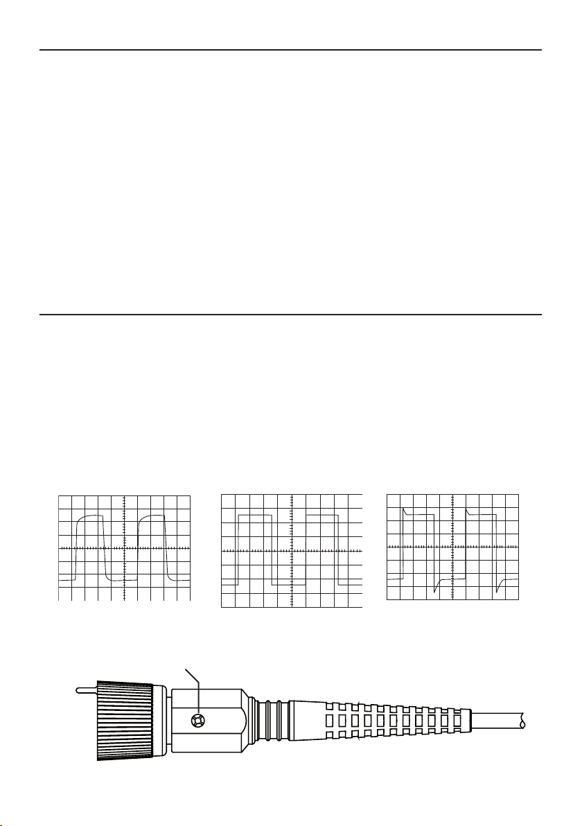
LF compensation is performed by connecting the probe to the PROBE COMPENSATION output on the
oscilloscope front panel and adjusting the LF compensation trimmer to optimum square wave response. For
clarification see below figures.
undercompensated
optimum overcompensated
LF Compensation Trimmer
Page 7
7
Adjustment Procedures R&S RT-ZP10
HF Compensation
It is typically not necessary to adjust HF compensation unless the probe is being used with an oscilloscope
having large differences in input characteristics to the oscilloscope that was used for factory adjustment.
We recommend to use the following equipment for proper HF compensation:
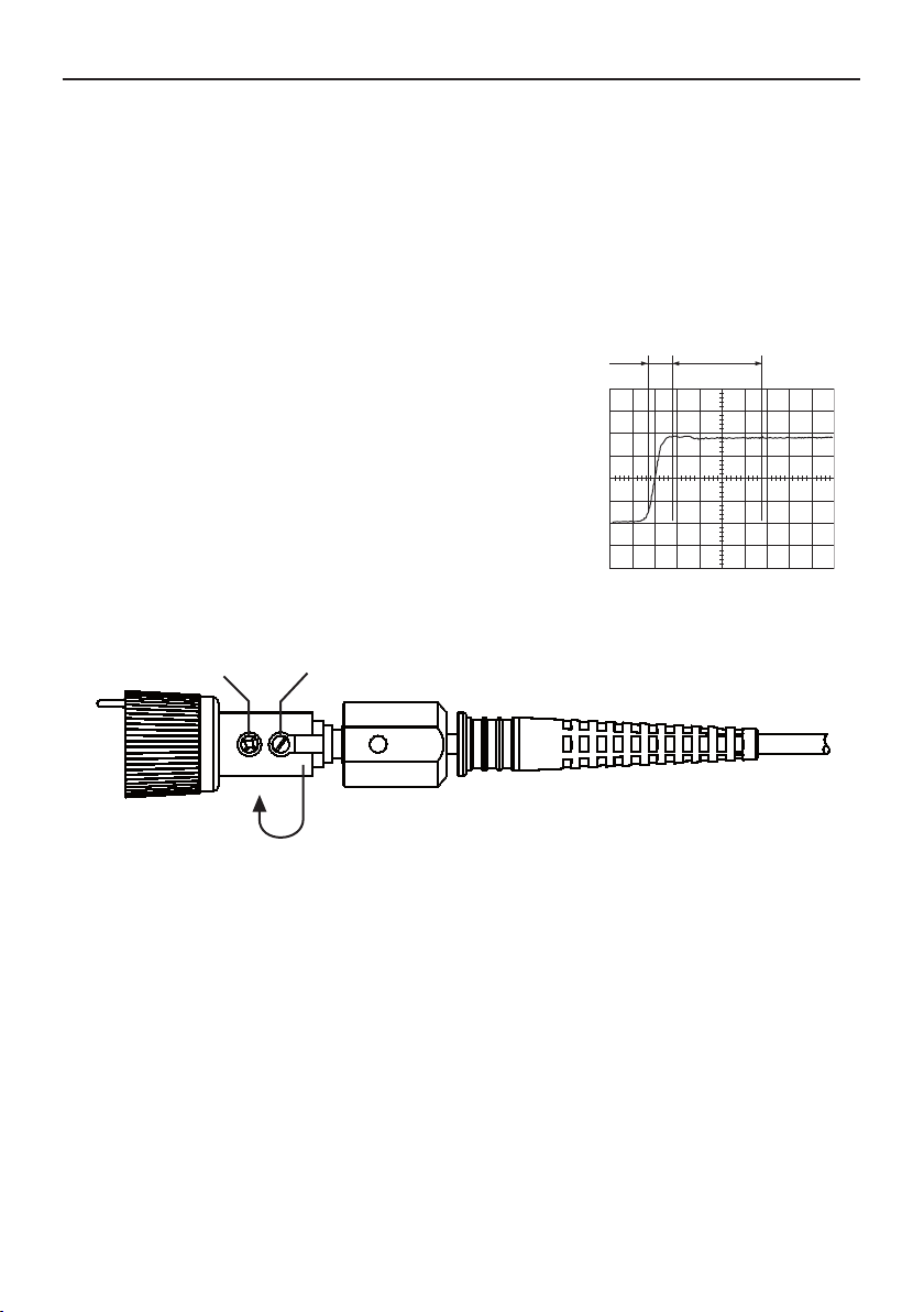
Rectangular wave generator with a rise time faster than 700 ps, 50 Ohm feed-through and probe BNC adapter.
T
T
1
HF adjustment is performed by connecting the probe to the rectangular
wave generator. Adjust trimmers (T
response.
is used for rise time adjustment.
T
1
T2 influences probe response time.
and T2) for optimum square wave
1
2
optimum
LF Compensation T
1
180° T
2
Page 8
8
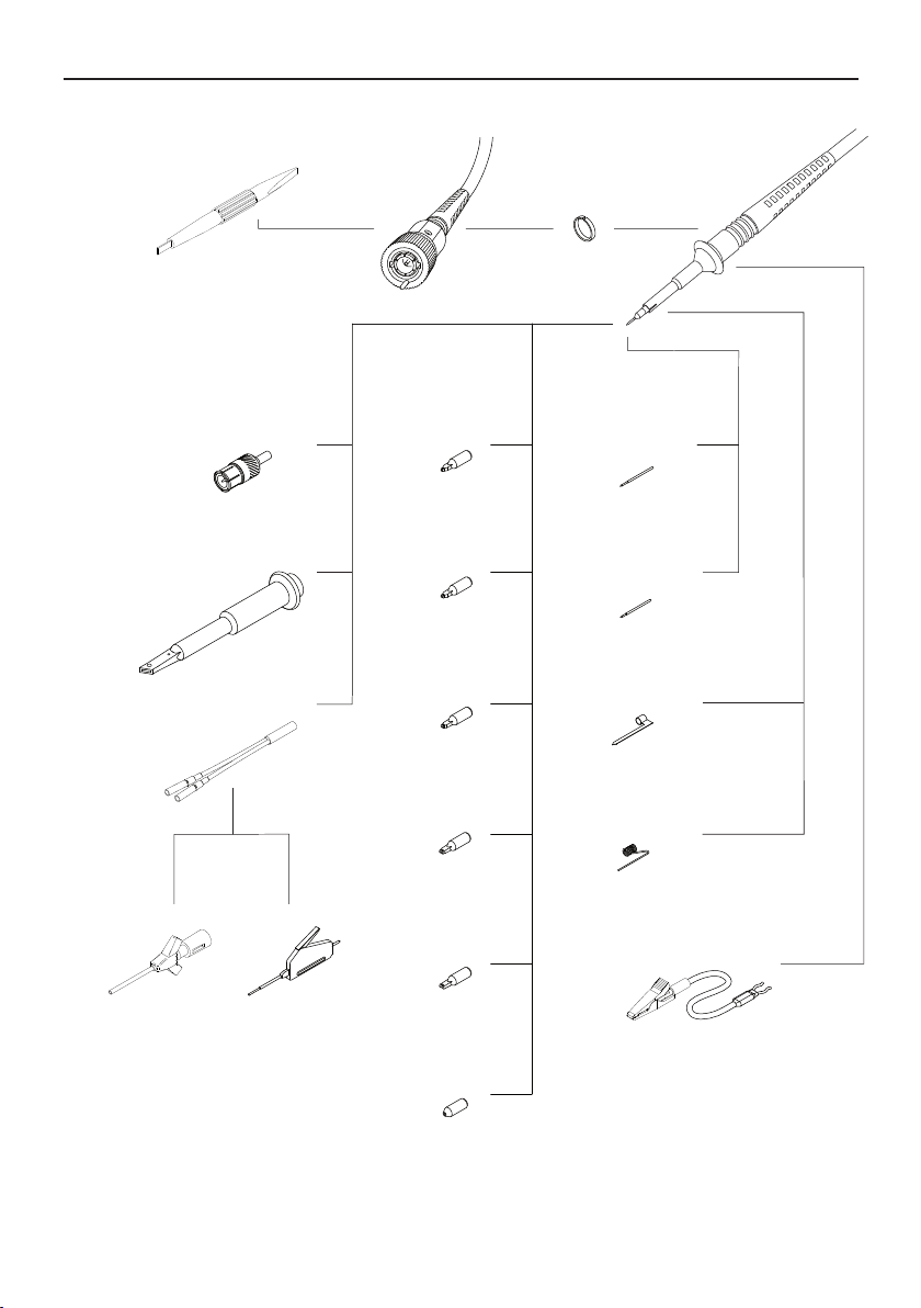
Adjustment
Tool
Coding Rings (set)
3x4 colors
IC-Cap 2.5
0.65 mm pitch; blue
IC-Cap 2.5
0.5 mm pitch; green
IC-Cap 2.5
0.8 mm pitch; gray
Insulating Cap 2.5
IC-Cap 2.5
1.27 mm pitch; black
IC-Cap 2.5
1.0 mm pitch; brown
Solid Tip
CuBe 0.5 mm
Spring Tip
gold plated 0.5 mm
Ground Spring 2.5
Ground Blade 2.5
Ground Lead 15 cm
BNC Adapter 2.5
Sprung Hook 2.5
Dual Adapter 2.5 to
0.8 mm sockets
Micro Clip
Mini Clip
Probe Accessories R&S RT-ZP10
Page 9
9
Scope of Delivery R&S RT-ZP10
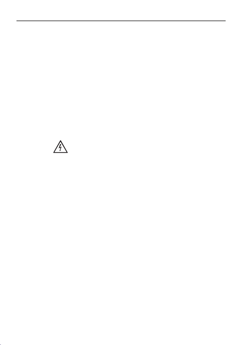
The following items are included in the scope of delivery. Please check the delivery for completeness.
RT-ZP10 500 MHz passive voltage probe (Order No. 1409.7550.00)
Item Qty
Adjustment Tool 1
Coding Rings (set) 3x4 Colors 1
Ground Lead 15 cm 1
Ground Spring 2.5 1
Operating Manual 1
Probe 1
Solid Tip CuBe 0.5 mm 1
Spring Tip gold plated 0.5 mm 1
Sprung Hook 2.5 1
(1) installed in probe
(2) plugged on probe
Use ground lead only for connections to earth ground.
(1)
(2)
Page 10
10
Optional Accessories R&S RT-ZP10
The following accessory sets can be ordered separately.
RT-ZA1 Accessory Kit (Order No. 1409.7566.02)
Item Qty
BNC Adapter 2.5 1
Coding Rings (set) 3x4 Colors 1
Dual Adapter 2.5 to 0.8 mm sockets 1
Ground Blade 2.5 1
Ground Lead 15 cm 1
Ground Spring 2.5 5
IC-Cap 2.5 0.5 mm pitch; green 1
IC-Cap 2.5 0.65 mm pitch; blue 1
IC-Cap 2.5 0.8 mm pitch; gray 1
IC-Cap 2.5 1.0 mm pitch; brown 1
IC-Cap 2.5 1.27 mm pitch; black 1
Insulating Cap 2.5 1
Solid Tip CuBe 0.5 mm 5
Sprung Hook 2.5 1
Spring Tip gold plated 0.5 mm 5
RT-ZA4 Mini Clips (Order No. 1416.0428.02)
Mini Clip 10
Adjustment Tool 1
Item Qty
RT-ZA5 Micro Clips (Order No. 1416.0434.02)
Micro Clip 4
The BNC Adapter is rated: 42 V peak AC + DC
The accessories provided with the probe have been safety tested. Do not use
any other accessories than those “originally” provided.
Item Qty
Page 11
11
Handling R&S RT-ZP10
Handle with care especially when fitted with the extra thin and sharp spring contact tip to avoid
any injury. Note that the probe cable is a sensitive part of the probe. Do not damage
through excessive bending or pulling. Avoid mechanical shock to this product in general to
guarantee accurate performance and protection.
Cleaning
To clean the exterior of the probe use a soft cloth moistened with either distillated water or isopropyl alcohol.
Before use allow the probe to dry completely.
Changing the Probe Tip
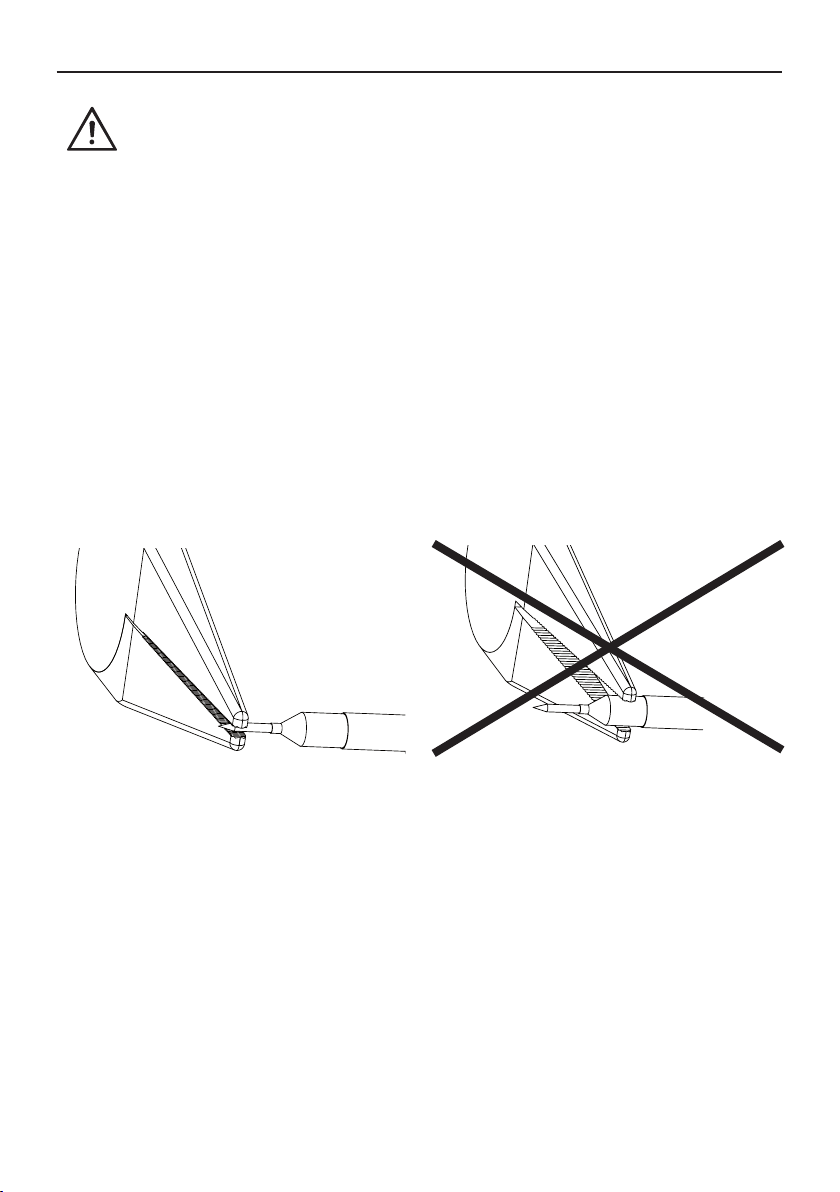
To change the probe tip use pliers to grip and pull it carefully straight out of its contact socket, along the
axis of the probe. Do not grip the white plastic insulator or the housing with pliers, because the tip could be
squeezed and cannot be removed and respectively the probe could be damaged.
If the probe tip is removed, the new tip can be inserted with pliers into the contact socket, along the axis
of the probe. In order to insert the probe tip completely into the housing, press the probe tip against a hard
surface carefully.
Use pliers to grip and pull the probe tip carefully out
of its contact socket.
Do not grip the white plastic insulator or the probe
housing with pliers.
Page 12

Copyright®2009 ROHDE & SCHWARZ All rights reserved.
Information in this publication supersedes that in all previously published material.
Specifications are subject to change without notice.
M59-711-R01 Revision A-December 2008
 Loading...