

Page 1

R&S®RTB2000
❙ 70MHz to 300MHz
❙ 10-bit ADC
Digital Oscilloscope
Power of ten
❙ 10 Msample standard memory
❙ 10.1" capacitive touchscreen
year
Product Brochure | Version 04.00
Page 2

R&S®RTB2000
Digital Oscilloscope
At a glance
The largest display (10.1") with the highest resolution of
1280×800 pixel in its class, a capacitive touchscreen to
quickly navigate in pop-up menus and a touch function to
easily adjust scaling, to zoom in or to move a waveform –
works just like your smartphone.
The 10-bit A/D converter yields up to a four-fold improvement compared to conventional 8-bit A/D converters. You
get sharper waveforms with more signal details.
Power of ten (10-bit ADC, 10 Msample memory
and 10.1" touchscreen) combined with smart
operating concepts make the R&S®RTB2000
digital oscilloscope the perfect tool for university
laboratories, for troubleshooting embedded designs
during development and for production and service
departments.
Rohde & Schwarz stands for quality, precision and innovation in all fields of wireless communications. As an
independent, family-owned company, Rohde & Schwarz
finances its growth from its own funds. The company is
not bound by short-term, quarterly results. It plans for
the long term, which greatly benefits customers. Purchasing Rohde & Schwarz products is a safe investment
for the future.
10Msample memory depth is available on each channel
if all channels are active. When interleaved, 20Msample
are available. That is 10 times more than comparable oscilloscopes offer. This captures longer signal sequences for
more analysis results.
The R&S®RTB2000 gives users more than just an oscilloscope. It also includes a logic analyzer, protocol analyzer,
waveform and pattern generator and digital voltmeter.
Dedicated operating modes for frequency analysis, mask
tests and long data acquisitions are also integrated. Debugging all kinds of electronic systems is easy and efficient – and satisfies the all-important rule of investment
protection at a very attractive price.
2
Page 3

R&S®RTB2000
Digital Oscilloscope
Benefits and
key features
See small signal details in the presence of large
signals
❙ 10-bit vertical resolution
❙ 1mV/div: full measurement bandwidth and low noise
▷ page 4
Capture more time at full bandwidth
❙ 10 Msample standard and 20 Msample interleaved
❙ Segmented memory: 160Msample with history function
❙ Maintain fast sampling rates at all times
▷ page 5
10.1" high-resolution capacitive touchscreen with
gesture support
❙ 10.1" high-resolution capacitive touch display
❙ Gesture support as on your smartphone
❙ Fast access to important tools
▷ page 6
The best choice for education
❙ Ready for the teaching lab
❙ X-in-1 integration saves space and costs
▷ page 10
R&S®HMO1002/1202 R&S®RTB2000
Number of scope channels 2 2/4
Bandwidth in MHz 50, 70, 100, 200, 300 70, 100, 200, 300
Max. sample rate in Gsample/s 1/channel, 2 interleaved 1.25/channel, 2.5 interleaved
Max. memory depth in Msample 1/channel, 2 interleaved 10/channel, 20 interleaved
Vertical bits (ADC) 8 10
Minimal input sensitivity 1mV/div 1mV/div
Display 6,5", 640×480 pixel 10.1" capacitive touchscreen, 1280×800 pixel
Update rate 10 000waveforms/s 50 000waveforms/s
MSO 8channels, 1 Gsample/s 16channels, 1.25Gsample/s
2
Protocol (optional) I
Generator(s) 1 ARB, 4-bit pattern generator 1 ARB, 4-bit pattern generator
Math +, –, *, /, FFT (128k point) +, –, *, /, FFT (128k point)
Rohde & Schwarz R&S®RTB2000 Digital Oscilloscope 3
C, SPI, UART/RS-232/RS-422/RS-485, CAN, LIN I2C, SPI, UART/RS-232/RS-422/RS-485, CAN, LIN
Page 4

See small signal
details in the
presence of large
signals
❙ 10-bit A/D converter resolution
❙ 1mV/div true vertical resolution
10-bit A/D converter: uncovers even small signal
details
Traditional scope
❙ 8-bit vertical resolution
¸RTB2000
❙ 10-bit vertical resolution
10-bit vertical resolution
The R&S®RTB2000 features a customized Rohde & Schwarz
engineered 10-bit A/D converter that delivers a fourfold improvement compared to conventional 8-bit A/D
converters.
The increased resolution results in sharper waveforms with
more signal details that would otherwise be missed. One
example is the characterization of switched-mode power
supplies. The voltages across the switching device must
be determined during the on/off times within the same acquisition. For precise measurements of small voltage components, a high resolution of more than 8-bit is essential.
1mV/div: full measurement bandwidth and low
noise
The R&S®RTB2000 oscilloscope offers an outstanding sensitivity down to 1 mV/div. Traditional oscilloscopes reach
this level of input sensitivity only by employing softwarebased magnification or by limiting the bandwidth. The
R&S®RTB2000 oscilloscope shows the signal’s real sampling points over the full measurement bandwidth – even
at 1mV/div. This ensures high measurement accuracy.
4 mV
Finest resolution for a 1 V signal
1 mV
The accuracy of a signal displayed on the screen depends
on the oscilloscope’s inherent noise. The R&S®RTB2000
oscilloscope precisely measures even at the smallest vertical resolution by using low-noise frontends and state-ofthe-art A/D converters.
The Rohde & Schwarz designed
10-bit A/D converter ensures
highest signal fidelity at highest
resolution.
4
Page 5

Capture more time
at full bandwidth
❙ 10Msample standard, 20Msample interleaved
❙ 160Msample segmented memory with more than
13 000recordings
❙ History mode: analysis of past acquisitions
❙ 1.25Gsample/s, 2.5Gsample/s interleaved
10 Msample standard and 20 Msample
interleaved
The R&S®RTB2000 offers a class-leading memory depth:
10Msample per channel are available, even 20Msample
in interleaved mode. This is 10 times more than similar
oscilloscopes in the same instrument class. The user captures longer acquisition sequences even at high sampling
rates, e.g. when analyzing transients of switched-mode
power supplies, and thus benefits from more detailed anal-
ysis results.
Segmented memory: 160Msample with history
function
The R&S®RTB-K15 option with deep, segmented memory
analyzes signal sequences over a long observation period.
For example, protocol-based signals with communications
gaps such as I
onds or minutes. Thanks to the variable segment size from
10ksample to 10Msample, the 160Msample memory is
optimally utilized; more than 13 000 cohesive individual recordings are possible.
In history mode, previous acquisitions to the maximum
segmented memory depth of 160Msample are available
for further analysis. Mask tests, QuickMeas function and
FFT, for example, can be used for further analysis.
2
C or SPI can be captured over several sec-
Maintain fast sampling rates at all times
Signal faults and important events are detected better
with an oscilloscope that offers a high sampling rate.
Many applications require long acquisition cycles, for instance when analyzing serial protocols. With a sampling
rate of up to 2.5Gsample/s and a memory depth of up to
20Msample, the R&S®RTB2000 oscilloscopes really excel
here. They display signals accurately, right down to the details and even for long sequences.
10 to 100 times more memory depth compared to traditional
oscilloscopes in the same instrument class
Capture the longest time periods with class-leading 160Msample memory
¸RTB2000
16010
Comparable
scopes
Standard memory Optional segmented memory
Rohde & Schwarz R&S®RTB2000 Digital Oscilloscope 5
1
Page 6
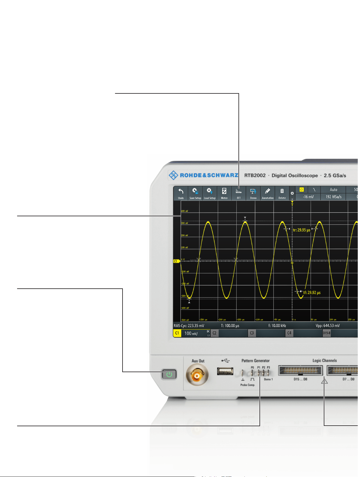
10.1" high-resolution capacitive touchscreen with gesture support
Quick access to important tools
❙ Drag & drop use of analysis tools
❙ Toolbar for access to functions
❙ Sidebar for intuitive conguration of functions
Easily customizable
waveform display with
R&S®SmartGrid technology
❙ Congurable display
❙ Resizable waveform areas
❙ Scales labeled on all axes
10-second boot-up time
Integrated waveform and
pattern generator up to
50Mbit/s
❙ Output of sine, square/pulse, ramp
and noise waveforms
❙ Output of arbitrary waveform les
and 4-bit signal patterns
6
Page 7
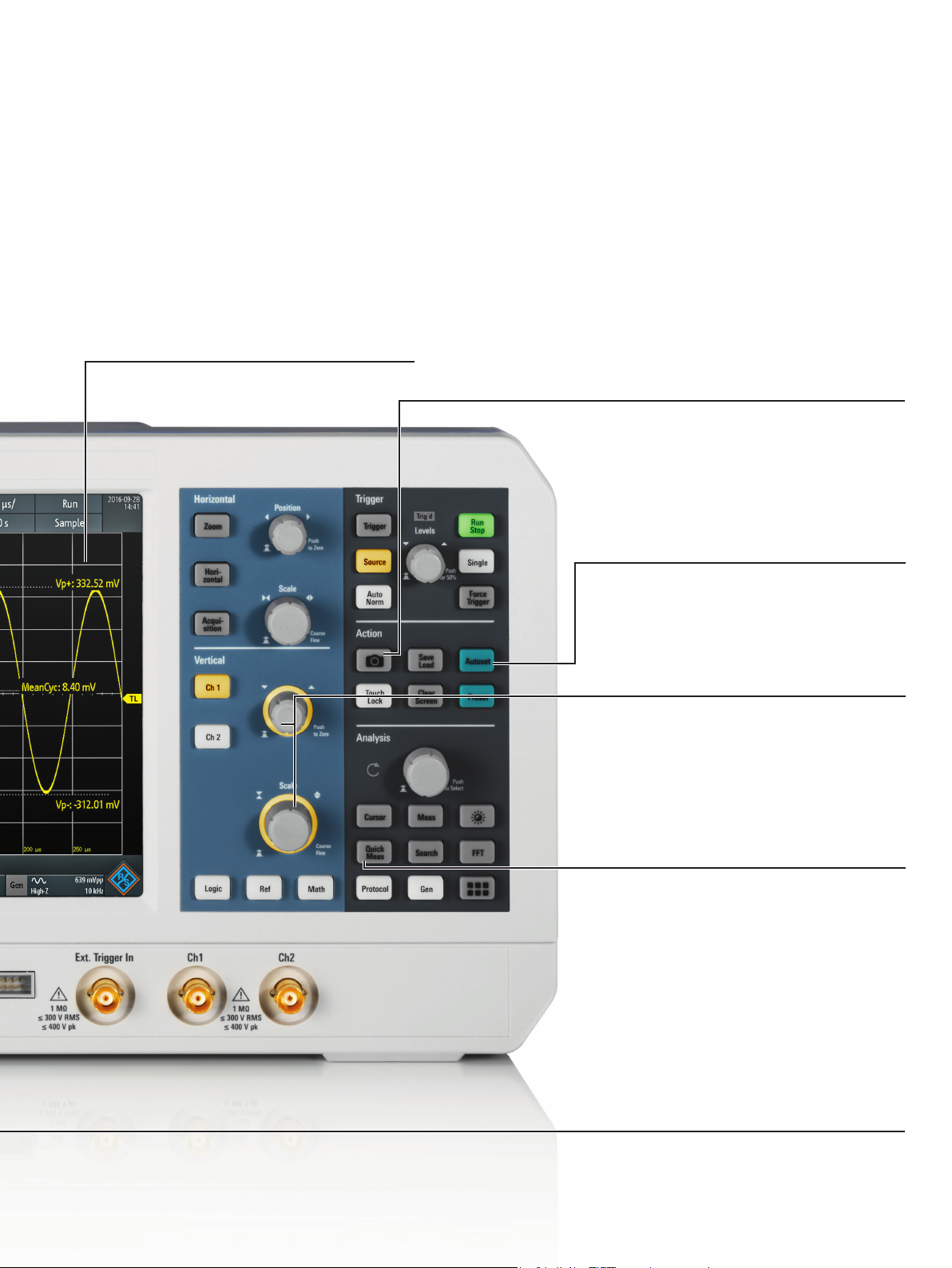
10.1" high-resolution capacitive
touchscreen with gesture support
❙ Gesture support for scaling and zooming
❙ More than twice the display area compared to
comparable oscilloscopes
❙ Nine times the pixels of similiar oscilloscopes:
1280×800 pixel resolution
❙ 12 horizontal grid lines for more signal details
Documentation of results at
the push of a button
❙ Documentation as a screenshot or
of instrument settings
Autoset function
❙ Automatic selection of vertical,
horizontal and trigger settings for
optimal viewing of active signals
❙ Setting of FFT parameters
Color-coded controls
indicate the selected
channel
QuickMeas: results at the
push of a button
❙ Graphical display of key
measurement results for the active
signal
Integrated logic analyzer
(MSO)
❙ 16 additional digital channels
❙ Synchronous and time-correlated
analysis of analog and digital
components of embedded designs
❙ Fully retrottable
Rohde & Schwarz R&S®RTB2000 Digital Oscilloscope 7
Page 8
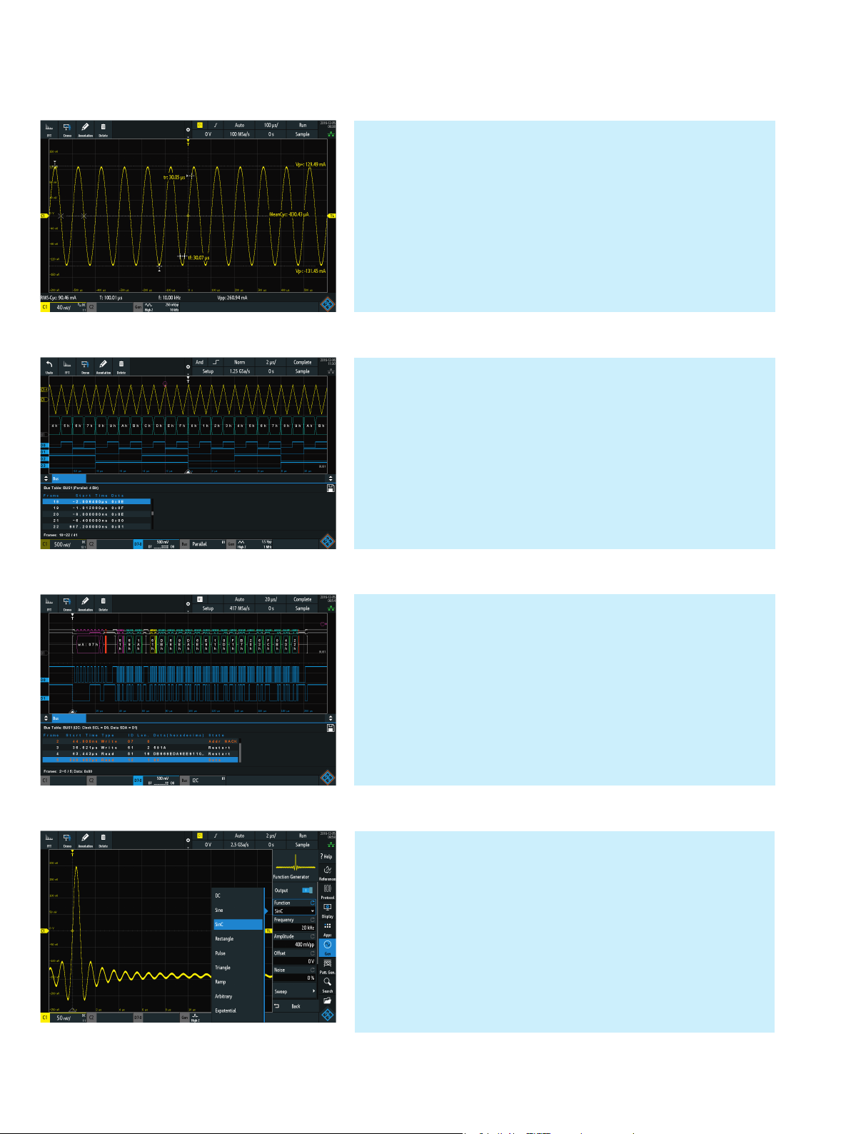
X-in-1 oscilloscope
Oscilloscope
With a sampling rate of up to 2.5Gsample/s and a memory depth
of up to 20Msample, the R&S®RTB2000 oscilloscope excels in its
class. A waveform update rate of more than 50 000 waveforms/s
ensures a responsive instrument that reliably catches signal faults.
Included standard tools provide quick results, e.g. QuickMeas,
mask tests, FFT, math, cursors and automatic measurements, including statistics.
Logic analyzer
The R&S®RTB-B1 option turns every R&S®RTB2000 into an intuitive-to-use MSO with 16 additional digital channels. The oscilloscope captures and analyzes signals from analog and digital
components of an embedded design – synchronously and timecorrelated to each other. For example, the delay between input and
output of an A/D converter can conveniently be determined using
the cursor measurements.
Protocol analyzer
Protocols such as I2C, SPI and CAN/LIN frequently transfer control
messages between integrated circuits. The R&S®RTB2000 has versatile options for protocol-specific triggering and decoding of serial
interfaces. Selective acquisition and analysis of relevant events and
data is possible. With the hardware-based implementation, smooth
operation and a high update rate is ensured even for long acquisitions. This is advantageous, for example, to capture multiple packetized serial bus signals.
Waveform and pattern generator
The integrated R&S®RTB-B6 waveform and pattern generator up to
50Mbit/s is useful for educational purposes and for implementing
prototype hardware. Apart from the common sine, square/pulse,
ramp and noise waveforms, it outputs arbitrary waveforms and
4-bit signal patterns. Waveforms and patterns can be imported as
CSV files or copied from oscilloscope waveforms. Before playing
signals back, the user can preview them to quickly check signal
correctness. Predefined patterns for e.g. I
CAN/LIN can be used.
2
C, SPI, UART and
8
Page 9
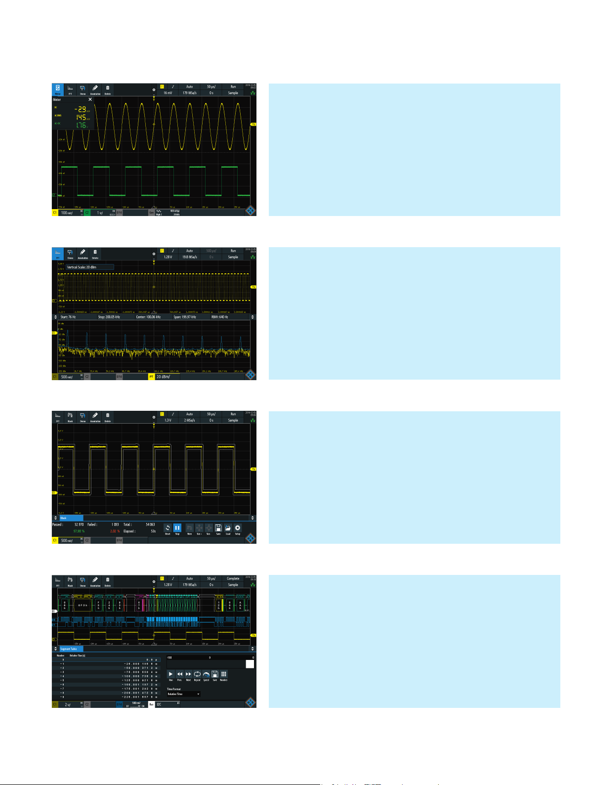
Digital voltmeter
The R&S®RTB2000 features a three-digit voltmeter (DVM) and sixdigit frequency counter on each channel for simultaneous measurements. Measurement functions include DC, AC+DC
– included in scope of delivery.
AC
RMS
RMS
and
Frequency analysis mode
Difficult-to-find faults often result from the interaction between
time and frequency signals. The FFT function of the R&S®RTB2000
is activated with the push on a button and by just entering center
frequency and span. Due to the high-performance FFT functionality of the R&S®RTB2000 oscilloscopes, signals can be analyzed
with up to 128k point. Other practical tools include cursor measurements and autoset in frequency domain.
Mask test mode
Mask tests quickly reveal whether a specific signal lies within defined tolerance limits. By using statistical pass/fail evaluation, they
assess quality and stability of a DUT. Signal anomalies and unexpected results are quickly identified. When the mask is violated,
the measurement stops. Each violation can generate a pulse output at the AUX-OUT connector on the R&S®RTB2000. This pulse
output can be used to trigger actions in the measurement setup.
History and segmented memory mode
The R&S®RTB-K15 history function option increases the memory
from 10Msample to 160Msample. Users scroll through past acquisitions and analyze the data using all of the oscilloscope tools,
e.g. protocol decode and logic channels. Serial protocol and pulse
sequences are recorded practically without interruptions.
Rohde & Schwarz R&S®RTB2000 Digital Oscilloscope 9
Page 10

The best choice for
education
Professors especially like the password-protected education mode that disables automatic functions such as
Autoset. This helps students understand the concepts.
The built-in web server functionality enables professors to
display their oscilloscope screen content to the classroom
and over a network.
❙ Education mode to disable automatic functions
❙ X-in-1 integration
Ready for the teaching lab
In the teaching lab, the R&S®RTB2000 oscilloscope is the
perfect choice to teach students how to measure with an
oscilloscope. This Rohde & Schwarz oscilloscope has an
easy-to-use concept combined with state-of-the-art technology – at an affordable price. Students appreciate the
intuitive and quick access to frequently used functions via
dedicated buttons and capacitive touchscreen operation.
And they solve their lab tutorial without worrying about oscilloscope functionality.
The large 10.1" high-resolution screen shows every signal
detail, and one instrument can be shared among several
students. Reports can be efficiently created with the handy
and flexible screen annotation tool.
Updating and monitoring hundreds of units? The remote
interfaces make these tasks as easy as switching on a light
bulb.
X-in-1 integration saves space and costs
With the R&S®RTB2000, students and professors in a
university lab get an oscilloscope plus logic and protocol
analyzer, waveform and pattern generator and digital voltmeter. Dedicated operation modes for frequency analysis,
mask tests and long data acquisitions are also integrated.
Debugging all kinds of electronic systems is easy and efficient – and satisfies the all-important rule of investment
protection at a very attractive price. The compact design
and small footprint save precious bench space in the lab.
Perfect instruments for everyday use at universities and colleges thanks to
diverse functionality, rugged design and small footprint.
10
Page 11
And there is so
much more ...
❙ Efcient reporting capabilities
❙ Localized GUI and online help
❙ Fully upgradable via software licenses
❙ Web server functionality for instrument access
❙ Extensive range of probes and accessories
Grows with your needs
The R&S®RTB2000 oscilloscopes flexibly adapt to needed
project updates by installing software licenses. This applies
to e.g. triggering and decoding of serial protocols and the
history and segmented memory mode. The waveform and
pattern generator and the MSO capabilities
and just need to be activated. Via keycode, the bandwidth
can be upgraded up to 300 MHz. All this makes retrofitting
really easy.
Multilingual support: choose among thirteen
languages
The R&S®RTB2000 oscilloscope’s user interface and online
help support thirteen languages (English, German, French,
Spanish, Italian, Portuguese, Czech, Polish, Russian, simplified and traditional Chinese, Korean and Japanese). Users can change the language in just a few seconds while
the instrument is running.
1)
are built-in
Protection of data
The secure erase function protects sensitive data. This
function removes all user data and settings, including device setups and reference waveforms.
Connectivity
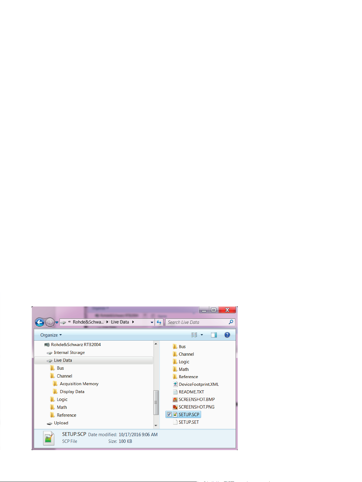
The R&S®RTB2000 can be directly connected to a PC via
the built-in USB host and USB device ports. The USB host
transfers screenshots or instrument settings to a USB
stick. Media transfer protocol (MTP) implementation ensures seamless integration. The USB device port and the
LAN interface also enable remote control. The built-in web
server functionality allows users to control the oscilloscope
and display their screen content to an audience. Data and
programming interfaces are included, e.g. for seamless
MATLAB® integration.
Probes to measure accurately
A comprehensive probe portfolio for accurate measurements rounds out the R&S®RTB2000 oscilloscope offering. Each R&S®RTB2000 is delivered with passive voltage
probes. Single-ended high-voltage probes, differential
probes and current probes are also available and can be
ordered additionally.
▷ For more information, see the product brochure:
Probes and accessories, Rohde & Schwarz digital oscilloscopes (PD 3606.8866.12).
1)
The R&S ®RTB -B1 MSO option additionally cont ains two logic probes with
16digital channels.
With the USB MTP implementation, easy access
to live channel data and screenshots and inte-
gration into customers computing environment
is possible.
Rohde & Schwarz R&S®RTB2000 Digital Oscilloscope 11
Page 12

Specifications in brief
Specifications in brief
Vertical system
Number of channels R&S®RTB2002; R&S®RTB2004 2; 4
Bandwidth (–3dB) R&S®RTB2002/2004 (with R&S®RTB-B2x1,
R&S®RTB-B2x2 and R&S®RTB-B2x3 options)
Rise time (calculated) R&S®RTB2002/2004 (with R&S®RTB-B2x1,
R&S®RTB-B2x2 and R&S®RTB-B2x3 options)
Input impedance 1 MΩ ± 2 % with 19 pF ± 2 pF (meas.)
input sensitivity max. bandwidth in all ranges 1mV/div to 5V/div
DC gain accuracy offset and position = 0, maximum operating temperature change of ±5 °C after self-alignment
input sensitivity > 5 mV/div ± 1.5 % of full scale
input sensitivity ≤ 5 mV/div ± 2 % of full scale
ADC resolution 10-bit, up to 16-bit with high resolution decimation
Acquisition system
Maximum realtime sampling rate 1.25 Gsample/s; 2.5 Gsample/s, interleaved
Acquisition memory standard;
with R&S®RTB-K15 option
Horizontal system
Timebase range selectable between 1ns/div and 500s/div
Trigger system
Trigger types standard edge, width, video (PAL, NTSC, SECAM, PAL-M, SDTV 576i,
option I
Analysis and measurement functions
QuickMeas at the push of a button, measurement values are
continuously written onto the waveform
Waveform mathematics addition, subtraction, multiplication, division, FFT
MSO option
Digital channels 16 (2 logic probes)
Sampling rate 1.25 Gsample/s
Acquisition memory 10 Msample
Waveform generator
Resolution, sample rate 14-bit, 250 Msample/s
Amplitude high-Z; 50 Ω 20 mV to 5 V (V
DC offset high-Z; 50 Ω ±2.5 V; ±1.25 V
Signal forms frequency ranges sine 0.1 Hz to 25 MHz
pulse/rectangle 0.1 Hz to 10 MHz
ramp/triangle 0.1 Hz to 1 MHz
noise max. 25 MHz
Arbitrary sampling rate; memory depth max. 10 Msample/s; 16k point
General data
Screen 10.1" WXGA TFT color display (1280 × 800 pixel)
Interfaces USB host with MTP, USB device, LAN, powerful web server
Audible noise maximum sound pressure level at a distance
of 1.0 m
Dimensions W × H × D 390 mm × 220 mm × 152 mm (15.4 in × 8.66 in × 5.98 in)
Weight 2.5 kg (5.5 lb)
70 MHz, 100 MHz, 200 MHz, 300 MHz
5 ns, 3.5 ns, 1.75 ns, 1.15 ns
10Msample; 20Msample, interleaved;
160Msample segmented memory
HDTV 720p, HDTV 1080i, HDTV1080p), pattern, line, serial
bus
2
C, SPI, UART/RS-232/RS-422/RS-485, CAN/LIN
peak-to-peak voltage, pos. peak, neg. peak, rise time, fall
time, mean value, RMS value, time, period, frequency
); 10 mV to 2.5 V (Vpp)
pp
for remote display and operation
28.3 dB(A)
12
Page 13

Ordering information
Designation Type Order No.
Choose your R&S®RTB2000 base model
Digital Oscilloscope, 70 MHz, 2 channels R&S®RTB2002 1333.1005.02
Digital Oscilloscope, 70 MHz, 4 channels R&S®RTB2004 1333.1005.04
Base unit (including standard accessories: R&S®RT-ZP03 passive probe per channel, power cord)
Choose your bandwidth upgrade
Upgrade of R&S®RTB2002 oscilloscopes to 100 MHz bandwidth R&S®RTB-B221 1333.1163.02
Upgrade of R&S®RTB2002 oscilloscopes to 200 MHz bandwidth R&S®RTB-B222 1333.1170.02
Upgrade of R&S®RTB2002 oscilloscopes to 300 MHz bandwidth R&S®RTB-B223 1333.1186.02
Upgrade of R&S®RTB2004 oscilloscopes to 100 MHz bandwidth R&S®RTB-B241 1333.1257.02
Upgrade of R&S®RTB2004 oscilloscopes to 200 MHz bandwidth R&S®RTB-B242 1333.1263.02
Upgrade of R&S®RTB2004 oscilloscopes to 300 MHz bandwidth R&S®RTB-B243 1333.1270.02
Choose your options
Mixed Signal Upgrade for non-MSO models, 250 MHz, incl. 2 × R&S®RT-ZL03 R&S®RTB-B1 1333.1105.02
Arbitrary Waveform Generator R&S®RTB-B6 1333.1111.02
2
C/SPI Serial Triggering and Decoding R&S®RTB-K1 1333.1011.02
I
UART/RS-232/RS-422/RS-485 Serial Triggering and Decoding R&S®RTB-K2 1333.1028.02
CAN/LIN Serial Triggering and Decoding R&S®RTB-K3 1333.1034.02
History and Segmented Memory R&S®RTB-K15 1333.1040.02
Application Package (-K1, -K2, -K3, -K5, -K6, -K7, -K15, -K31, -K32) R&S®RTB-PK1 1333.1092.02
Choose your additional probes
Single-ended passive probes
300 MHz, 10 MHz, 10:1/1:1, 10 MΩ/1 MΩ, 400 V, 12 pF/82 pF R&S®RT-ZP03 3622.2817.02
500 MHz, 500MHz, 10:1, 300 V (RMS), 10 pF R&S®RT-ZP05 3623.2927.02
500 MHz, 10 MΩ, 10:1, 400 V, 9.5 pF R&S®RTM-ZP10 1409.7708.02
38 MHz, 1 MΩ, 1:1, 55 V, 39 pF R&S®RT-ZP1X 1333.1370.02
High-voltage single-ended passive probes
250 MHz, 100:1, 100 MΩ, 850 V, 6.5 pF R&S®RT-ZH03 1333.0873.02
400 MHz, 100:1, 50 MΩ, 1000 V, 7.5 pF R&S®RT-ZH10 1409.7720.02
400 MHz, 1000:1, 50 MΩ, 1000 V, 7.5 pF R&S®RT-ZH11 1409.7737.02
Current probes
20 kHz, AC/DC, 10A/1000A R&S®RT-ZC02 1333.0850.02
100 kHz, AC/DC, 30 A R&S®RT-ZC03 1333.0844.02
10 MHz, AC/DC, 150 A R&S®RT-ZC10 1409.7750.02
100 MHz, AC/DC, 30 A R&S®RT-ZC20 1409.7766.02
120 MHz, AC/DC, 5 A R&S®RT-ZC30 1409.7772.02
Power Supply for current probes R&S®RT-ZA13 1409.7789.02
Active differential probes
100 MHz, 1000:1/100:1, 8 MΩ, 1000 V (RMS), 3.5 pF R&S®RT-ZD01 1422.0703.02
200 MHz, 10:1, 1 MΩ, 20 V diff., 3.5 pF R&S®RT-ZD02 1333.0821.02
Logic probes
Active 8 Channel Logic Probe R&S®RT-ZL03 1333.0715.02
Probe accessories
Feedthrough Termination 50Ω R&S®HZ22 3594.4015.02
Choose your accessories
Front Cover R&S®RTB-Z1 1333.1728.02
Soft Bag R&S®RTB-Z3 1333.1734.02
Rackmount Kit R&S®ZZA-RTB2K 1333.1711.02
Rohde & Schwarz R&S®RTB2000 Digital Oscilloscope 13
Page 14
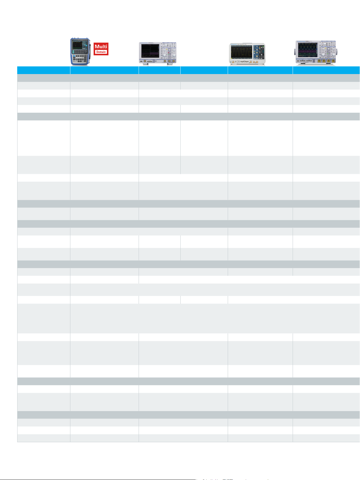
Oscilloscope portfolio
R&S® family RTH1000 HMO1002 HMO1202 RTB2000 HMO3000 RTM2000 RTE1000 RTO2000
Vertical
1)
Bandwidth 60/100/200/350/500 MHz
50/70/100 MHz 1)100/200/300 MHz 1)70/100//200/300 MHz
Number of channels 2 plus DMM/4 2 2/4 2/4 2/4 2/4 2/4 (only 4 channels in 4 GHz and 6 GHz model)
V/div 1MΩ 2 mV to 100 V 1 mV to 10 V 1 mV to 5 V 1 mV to 5 V 1 mV to 10 V 500 µV to 10 V 1 mV to 10 V (500 μV to 10 V)
V/div 50Ω – – 1 mV to 10 V – 1 mV to 5 V 1 mV to 2 V 500 µV to 5 V 1 mV to 1 V (500 μV to 1 V)
Horizontal
Sampling rate 1.25 Gsample/s per channel
(4-channel model);
2.5 Gsample/s per channel
(2-channel model);
5 Gsample/s (all channels
500Msample/s
per channel
1 Gsample/s
(2 channels
interleaved)
1 Gsample/s per
channel
2 Gsample/s (2 channels interleaved)
1.25 Gsample/s per channel;
2.5 Gsample/s (2 channels
interleaved)
interleaved)
Max. memory
(per channel/1 channel
active)
125 ksample (4-channel model);
250 ksample (2-channel model);
500 ksample
500 ksample;
1 Msample
1 Msample;
2 Msample
10 Msample; 20 Msample
(160 Msample in segmented
memory mode
Segmented memory option – option option option standard standard
Acquisition rate 50 000 waveforms/s 10 000 waveforms/s 50 000 waveforms/s 5000 waveforms/s
Trigger
Options advanced, digital trigger
(14 trigger types)
2)
elementary (5 trigger types) basic (6 trigger types) basic (9 trigger types) basic (7 trigger types) advanced, digital trigger (13 trigger types) advanced, digital trigger (14 trigger types), zone trigger
Mixed signal option
1)
No. of digital channels
Sampling rate of digital
8 16 16 16 16 16
1.25Gsample/s 500 Msample/s 1Gsample/s 1.25Gsample/s 1Gsample/s 2.5 Gsample/s 5Gsample/s 5Gsample/s
channels
Max. memory of digital
125ksample 500ksample 1 Msample 10 Msample 2Msample 10 Msample; 20 Msample 100Msample 200Msample
channels
Analysis
Cursor meas. types 3 11 13 12
Stand. meas. functions 33 31 31 47 47
Mask test elementary (tolerance mask around the signal) elementary (tolerance mask around the
1)
300/400/500 MHz
1)
2 Gsample/s per channel;
4 Gsample/s
(2 channels interleaved)
4 Msample;
2)
)
8 Msample
(200 000 waveforms/s in
segmented memory mode
2)
)
Mathematics elementary basic (math on math) elementary basic (math on math) advanced (formula editor) advanced (formula editor)
Serial protocols triggering and decoding
I2C, SPI, UART/RS-232/RS-422/RS-485, CAN/LIN I
1)
Display functions data logger – – – track
Applications
1)
high resolution frequency coun-
– – –
ter, advanced spectrum analysis, harmonics analysis
Compliance testing
1)
– – – – – – various options available, for details see data sheet
Display and operation
Size and resolution 7", color, 800 × 480 pixel 6.5", color, 640 × 480 pixel 10.1", color, 1280 × 800 pixel 6.5", color, 640 × 480 pixel
Operation optimized for touchscreen
operation, parallel button
operation
optimized for fast button operation optimized for touchscreen
operation, parallel button
operation
optimized for fast button
operation
General data
Size in mm (W × H × D) 201 × 293 × 74 285 × 175 × 140 390 × 220 × 152 285 × 175 × 220
Weight in kg 2.4 2.5 2.5 3.6 4.9 8.6 9.6
Battery lithium-ion, > 4 h – – – – – –
1)
Upgradeable.
2)
Requires an option.
14
Page 15
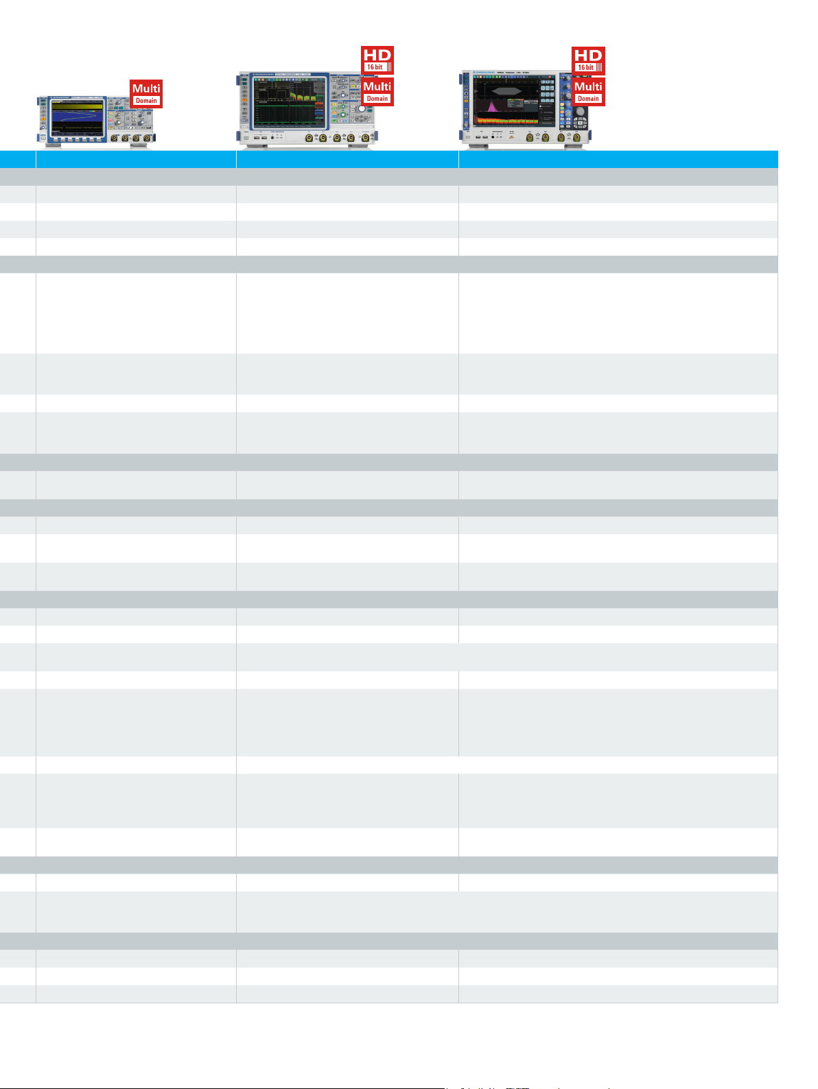
200/350/500 MHz/1 GHz
1)
200/350/500 MHz/1/1.5/2 GHz
1)
600 MHz/1/2/3/4/6 GHz
1)
2)
2)
2.5 Gsample/s per channel;
5 Gsample/s per channel 10 Gsample/s per channel;
5 Gsample/s (2 channels interleaved)
10 Msample; 20 Msample
(460 Msample in segmented memory
2)
)
mode
12 500 waveforms/s
(200 000 waveforms/s in segmented
memory mode
2)
)
standard: 10 Msample/40 Msample;
max. upgrade: 50 Msample/200 Msample
1 000 000 waveforms/s
(2 000 000 waveforms/s in
ultra- segmented memory mode)
14 3 3
advanced (freely configurable, hardware-based)
signal)
20 Gsample/s (2 channels interleaved in 4 GHz and 6 GHz model)
standard: 50 Msample/200 Msample;
max. upgrade: 1 Gsample/2 Gsample
1 000 000 waveforms/s
(3 000 000 waveforms/s in ultra-segmented memory mode)
2)
2
C, SPI, UART/RS-232/RS-422/RS-485,
CAN/LIN, I
2
S, MIL-STD-1553, ARINC 429
2)
power, digital voltmeter (DVM), spectrum
analysis and spectrogram
2
I
C, SPI, UART/RS-232/RS-422/RS-485,
CAN/LIN, I
2
S, MIL-STD-1553, ARINC 429,
FlexRay™, CAN FD, USB 2.0/HSIC, Ethernet,
Manchester, NRZ, SENT, SpaceWire, CXPI,
Broad-R Reach®
histogram, trend, track
2)
R&S®RTM applications
+
16-bit high definition, advanced spectrum
2
C, SPI, UART/RS-232/RS-422/RS-485, CAN/LIN, I2S,
I
MIL-STD-1553, ARINC 429, FlexRay™, CAN FD, USB 2.0/HSIC,
Ethernet, Manchester, NRZ, SENT, SpaceWire, CXPI, Broad-R
Reach®, MIPI RFFE, MDIO, 8b 10b, MIPI D-PHY, MIPI M-PHY, MIPI
M-PHY/ UniPro, serial pattern trigger
R&S®RTE applications
+
jitter, clock data recovery, I/Qdata, RF analysis
analysis and spectrogram
(PD3607.2684.22)
8.4", color, 1024 × 768 pixel 10.4", color, 1024 × 768 pixel 12.1", color, 1280 × 800 pixel
optimized for fast button operation optimized for touchscreen operation,
parallel button operation
403 × 189 × 142 427 × 249 × 204 427 × 249 × 204
Rohde & Schwarz R&S®RTB2000 Digital Oscilloscope 15
Page 16
Service that adds value
3607427012
❙ Worldwide
❙ Local and personalized
❙ Customized and flexible
❙ Uncompromising quality
❙ Long-term dependability
Rohde & Schwarz
The Rohde & Schwarz electronics group offers innovative
solutions in the following business fields: test and measurement, broadcast and media, secure communications,
cybersecurity, monitoring and network testing. Founded
more than 80 years ago, the independent company which
is headquartered in Munich, Germany, has an extensive
sales and service network with locations in more than
70countries.
Sustainable product design
❙ Environmental compatibility and eco-footprint
❙ Energy efciency and low emissions
❙ Longevity and optimized total cost of ownership
Cert ied Quali ty Managem ent
IS O 9 0 01
Certied Environmental Management
IS O 14 0 01
Rohde & Schwarz GmbH & Co. KG
www.rohde-schwarz.com
Rohde & Schwarz training
www.training.rohde-schwarz.com
Regional contact
❙ Europe, Africa, Middle East | +49 89 4129 12345
❙ North America | 1 888 TEST RSA (1 888 837 87 72)
❙ Latin America | +1 410 910 79 88
❙ Asia Pacic | +65 65 13 04 88
❙ China | +86 800 810 82 28 | +86 400 650 58 96
R&S® is a registered trademark of Rohde & Schwarz GmbH & Co. KG
Trade names are trademarks of the owners
PD 3607.4270.12 | Version 04.00 | June 2017 (sk)
R&S®RTB2000 Digital Oscilloscope
Data without tolerance limits is not binding | Subject to change
© 2017 Rohde & Schwarz GmbH & Co. KG | 81671 Munich, Germany
3607.4270.12 04.00 PDP 1 en
 Loading...