


R&S®RTM2000
Digital Oscilloscope
User Manual
(=A_J2)
1317.4726.02 ─ 10
User Manual
Test & Measurement

This document describes the following R&S®RTM models with firmware 05.8xx and higher:
●
R&S®RTM2022: 200 MHz, 2 channels (5710.0999K22)
●
R&S®RTM2024: 200 MHz, 4 channels (5710.0999K24)
●
R&S®RTM2032: 350 MHz, 2 channels (5710.0999K32)
●
R&S®RTM2034: 350 MHz, 4 channels (5710.0999K34)
●
R&S®RTM2052: 500 MHz, 2 channels (5710.0999K52)
●
R&S®RTM2054: 500 MHz, 4 channels (5710.0999K54)
●
R&S®RTM2102: 1 GHz, 2channels (5710.0999K02)
●
R&S®RTM2104: 1 GHz, 4 channels (5710.0999K04)
In addition to the base unit, the following options are described:
●
R&S®RTM-K1 (1305.0295.02), I²C/SPI
●
R&S®RTM-K2 (1305.0308.02), UART/RS232
●
R&S®RTM-K3 (1317.3065.02), CAN/LIN
●
R&S®RTM-K5 (5710.0882.02), I²S (audio)
●
R&S®RTM-K6 (1317.6835.02), MIL.1553
●
R&S®RTM-K7 (1317.6841.02), ARINC 429
●
R&S®RTM-K15 (5710.0899.02), History and segmented memory
●
R&S®RTM-K18 (1326.0959.02), Spectrum analysis
●
R&S®RTM-K31 (1317.5745.02), Power analysis
●
R&S®RTM-K32 (1326.0907.02), Digital voltmeter (DVM)
© 2016 Rohde & Schwarz GmbH & Co. KG
Mühldorfstr. 15, 81671 München, Germany
Phone: +49 89 41 29 - 0
Fax: +49 89 41 29 12 164
Email: info@rohde-schwarz.com
Internet: www.rohde-schwarz.com
Subject to change – Data without tolerance limits is not binding.
R&S® is a registered trademark of Rohde & Schwarz GmbH & Co. KG.
Trade names are trademarks of the owners.
The following abbreviations are used throughout this manual: R&S®RTM2000 is abbreviated as R&S RTM.

Basic Safety Instructions
Symbol
Meaning
Symbol
Meaning
Notice, general danger location
Observe product documentation
ON/OFF Power
Caution when handling heavy equipment
Standby indication
Danger of electric shock
Direct current (DC)
Always read through and comply with the following safety instructions!
All plants and locations of the Rohde & Schwarz group of companies make every effort to keep the safety
standards of our products up to date and to offer our customers the highest possible degree of safety. Our
products and the auxiliary equipment they require are designed, built and tested in accordance with the
safety standards that apply in each case. Compliance with these standards is continuously monitored by
our quality assurance system. The product described here has been designed, built and tested in
accordance with the EC Certificate of Conformity and has left the manufacturer’s plant in a condition fully
complying with safety standards. To maintain this condition and to ensure safe operation, you must
observe all instructions and warnings provided in this manual. If you have any questions regarding these
safety instructions, the Rohde & Schwarz group of companies will be happy to answer them.
Furthermore, it is your responsibility to use the product in an appropriate manner. This product is designed
for use solely in industrial and laboratory environments or, if expressly permitted, also in the field and must
not be used in any way that may cause personal injury or property damage. You are responsible if the
product is used for any purpose other than its designated purpose or in disregard of the manufacturer's
instructions. The manufacturer shall assume no responsibility for such use of the product.
The product is used for its designated purpose if it is used in accordance with its product documentation
and within its performance limits (see data sheet, documentation, the following safety instructions). Using
the product requires technical skills and, in some cases, a basic knowledge of English. It is therefore
essential that only skilled and specialized staff or thoroughly trained personnel with the required skills be
allowed to use the product. If personal safety gear is required for using Rohde & Schwarz products, this
will be indicated at the appropriate place in the product documentation. Keep the basic safety instructions
and the product documentation in a safe place and pass them on to the subsequent users.
Observing the safety instructions will help prevent personal injury or damage of any kind caused by
dangerous situations. Therefore, carefully read through and adhere to the following safety instructions
before and when using the product. It is also absolutely essential to observe the additional safety
instructions on personal safety, for example, that appear in relevant parts of the product documentation. In
these safety instructions, the word "product" refers to all merchandise sold and distributed by the Rohde &
Schwarz group of companies, including instruments, systems and all accessories. For product-specific
information, see the data sheet and the product documentation.
Safety labels on products
The following safety labels are used on products to warn against risks and dangers.
1171.0000.42 - 08 Page 1

Basic Safety Instructions
Symbol
Meaning
Symbol
Meaning
Caution ! Hot surface
Alternating current (AC)
Protective conductor terminal
To identify any terminal which is intended for
connection to an external conductor for
protection against electric shock in case of a
fault, or the terminal of a protective earth
Direct/alternating current (DC/AC)
Earth (Ground)
Class II Equipment
to identify equipment meeting the safety
requirements specified for Class II equipment
(device protected by double or reinforced
insulation)
Frame or chassis Ground terminal
EU labeling for batteries and accumulators
For additional information, see section "Waste
disposal/Environmental protection", item 1.
Be careful when handling electrostatic sensitive
devices
EU labeling for separate collection of electrical
and electronic devices
For additional information, see section "Waste
disposal/Environmental protection", item 2.
Warning! Laser radiation
For additional information, see section
"Operation", item 7.
Indicates a hazardous situation which, if not avoided, will result in death or
serious injury.
Indicates a hazardous situation which, if not avoided, could result in death or
serious injury.
Indicates a hazardous situation which, if not avoided, could result in minor or
moderate injury.
Indicates information considered important, but not hazard-related, e.g.
messages relating to property damage.
In the product documentation, the word ATTENTION is used synonymously.
Signal words and their meaning
The following signal words are used in the product documentation in order to warn the reader about risks
and dangers.
These signal words are in accordance with the standard definition for civil applications in the European
Economic Area. Definitions that deviate from the standard definition may also exist in other economic
areas or military applications. It is therefore essential to make sure that the signal words described here
are always used only in connection with the related product documentation and the related product. The
use of signal words in connection with unrelated products or documentation can result in misinterpretation
and in personal injury or material damage.
1171.0000.42 - 08 Page 2

Basic Safety Instructions
Operating states and operating positions
The product may be operated only under the operating conditions and in the positions specified by the
manufacturer, without the product's ventilation being obstructed. If the manufacturer's specifications are
not observed, this can result in electric shock, fire and/or serious personal injury or death. Applicable local
or national safety regulations and rules for the prevention of accidents must be observed in all work
performed.
1. Unless otherwise specified, the following requirements apply to Rohde & Schwarz products:
predefined operating position is always with the housing floor facing down, IP protection 2X, use only
indoors, max. operating altitude 2000 m above sea level, max. transport altitude 4500 m above sea
level. A tolerance of ±10 % shall apply to the nominal voltage and ±5 % to the nominal frequency,
overvoltage category 2, pollution degree 2.
2. Do not place the product on surfaces, vehicles, cabinets or tables that for reasons of weight or stability
are unsuitable for this purpose. Always follow the manufacturer's installation instructions when
installing the product and fastening it to objects or structures (e.g. walls and shelves). An installation
that is not carried out as described in the product documentation could result in personal injury or
even death.
3. Do not place the product on heat-generating devices such as radiators or fan heaters. The ambient
temperature must not exceed the maximum temperature specified in the product documentation or in
the data sheet. Product overheating can cause electric shock, fire and/or serious personal injury or
even death.
Electrical safety
If the information on electrical safety is not observed either at all or to the extent necessary, electric shock,
fire and/or serious personal injury or death may occur.
1. Prior to switching on the product, always ensure that the nominal voltage setting on the product
matches the nominal voltage of the mains-supply network. If a different voltage is to be set, the power
fuse of the product may have to be changed accordingly.
2. In the case of products of safety class I with movable power cord and connector, operation is
permitted only on sockets with a protective conductor contact and protective conductor.
3. Intentionally breaking the protective conductor either in the feed line or in the product itself is not
permitted. Doing so can result in the danger of an electric shock from the product. If extension cords
or connector strips are implemented, they must be checked on a regular basis to ensure that they are
safe to use.
4. If there is no power switch for disconnecting the product from the mains, or if the power switch is not
suitable for this purpose, use the plug of the connecting cable to disconnect the product from the
mains. In such cases, always ensure that the power plug is easily reachable and accessible at all
times. For example, if the power plug is the disconnecting device, the length of the connecting cable
must not exceed 3 m. Functional or electronic switches are not suitable for providing disconnection
from the AC supply network. If products without power switches are integrated into racks or systems,
the disconnecting device must be provided at the system level.
5. Never use the product if the power cable is damaged. Check the power cables on a regular basis to
ensure that they are in proper operating condition. By taking appropriate safety measures and
carefully laying the power cable, ensure that the cable cannot be damaged and that no one can be
hurt by, for example, tripping over the cable or suffering an electric shock.
1171.0000.42 - 08 Page 3

Basic Safety Instructions
6. The product may be operated only from TN/TT supply networks fuse-protected with max. 16 A (higher
fuse only after consulting with the Rohde & Schwarz group of companies).
7. Do not insert the plug into sockets that are dusty or dirty. Insert the plug firmly and all the way into the
socket provided for this purpose. Otherwise, sparks that result in fire and/or injuries may occur.
8. Do not overload any sockets, extension cords or connector strips; doing so can cause fire or electric
shocks.
9. For measurements in circuits with voltages V
> 30 V, suitable measures (e.g. appropriate
rms
measuring equipment, fuse protection, current limiting, electrical separation, insulation) should be
taken to avoid any hazards.
10. Ensure that the connections with information technology equipment, e.g. PCs or other industrial
computers, comply with the IEC 60950-1 / EN 60950-1 or IEC 61010-1 / EN 61010-1 standards that
apply in each case.
11. Unless expressly permitted, never remove the cover or any part of the housing while the product is in
operation. Doing so will expose circuits and components and can lead to injuries, fire or damage to the
product.
12. If a product is to be permanently installed, the connection between the protective conductor terminal
on site and the product's protective conductor must be made first before any other connection is
made. The product may be installed and connected only by a licensed electrician.
13. For permanently installed equipment without built-in fuses, circuit breakers or similar protective
devices, the supply circuit must be fuse-protected in such a way that anyone who has access to the
product, as well as the product itself, is adequately protected from injury or damage.
14. Use suitable overvoltage protection to ensure that no overvoltage (such as that caused by a bolt of
lightning) can reach the product. Otherwise, the person operating the product will be exposed to the
danger of an electric shock.
15. Any object that is not designed to be placed in the openings of the housing must not be used for this
purpose. Doing so can cause short circuits inside the product and/or electric shocks, fire or injuries.
16. Unless specified otherwise, products are not liquid-proof (see also section "Operating states and
operating positions", item 1). Therefore, the equipment must be protected against penetration by
liquids. If the necessary precautions are not taken, the user may suffer electric shock or the product
itself may be damaged, which can also lead to personal injury.
17. Never use the product under conditions in which condensation has formed or can form in or on the
product, e.g. if the product has been moved from a cold to a warm environment. Penetration by water
increases the risk of electric shock.
18. Prior to cleaning the product, disconnect it completely from the power supply (e.g. AC supply network
or battery). Use a soft, non-linting cloth to clean the product. Never use chemical cleaning agents such
as alcohol, acetone or diluents for cellulose lacquers.
Operation
1. Operating the products requires special training and intense concentration. Make sure that persons
who use the products are physically, mentally and emotionally fit enough to do so; otherwise, injuries
or material damage may occur. It is the responsibility of the employer/operator to select suitable
personnel for operating the products.
1171.0000.42 - 08 Page 4

Basic Safety Instructions
2. Before you move or transport the product, read and observe the section titled "Transport".
3. As with all industrially manufactured goods, the use of substances that induce an allergic reaction
(allergens) such as nickel cannot be generally excluded. If you develop an allergic reaction (such as a
skin rash, frequent sneezing, red eyes or respiratory difficulties) when using a Rohde & Schwarz
product, consult a physician immediately to determine the cause and to prevent health problems or
stress.
4. Before you start processing the product mechanically and/or thermally, or before you take it apart, be
sure to read and pay special attention to the section titled "Waste disposal/Environmental protection",
item 1.
5. Depending on the function, certain products such as RF radio equipment can produce an elevated
level of electromagnetic radiation. Considering that unborn babies require increased protection,
pregnant women must be protected by appropriate measures. Persons with pacemakers may also be
exposed to risks from electromagnetic radiation. The employer/operator must evaluate workplaces
where there is a special risk of exposure to radiation and, if necessary, take measures to avert the
potential danger.
6. Should a fire occur, the product may release hazardous substances (gases, fluids, etc.) that can
cause health problems. Therefore, suitable measures must be taken, e.g. protective masks and
protective clothing must be worn.
7. Laser products are given warning labels that are standardized according to their laser class. Lasers
can cause biological harm due to the properties of their radiation and due to their extremely
concentrated electromagnetic power. If a laser product (e.g. a CD/DVD drive) is integrated into a
Rohde & Schwarz product, absolutely no other settings or functions may be used as described in the
product documentation. The objective is to prevent personal injury (e.g. due to laser beams).
8. EMC classes (in line with EN 55011/CISPR 11, and analogously with EN 55022/CISPR 22,
EN 55032/CISPR 32)
Class A equipment:
Equipment suitable for use in all environments except residential environments and environments
that are directly connected to a low-voltage supply network that supplies residential buildings
Note: Class A equipment is intended for use in an industrial environment. This equipment may
cause radio disturbances in residential environments, due to possible conducted as well as
radiated disturbances. In this case, the operator may be required to take appropriate measures to
eliminate these disturbances.
Class B equipment:
Equipment suitable for use in residential environments and environments that are directly
connected to a low-voltage supply network that supplies residential buildings
Repair and service
1. The product may be opened only by authorized, specially trained personnel. Before any work is
performed on the product or before the product is opened, it must be disconnected from the AC supply
network. Otherwise, personnel will be exposed to the risk of an electric shock.
1171.0000.42 - 08 Page 5

Basic Safety Instructions
2. Adjustments, replacement of parts, maintenance and repair may be performed only by electrical
experts authorized by Rohde & Schwarz. Only original parts may be used for replacing parts relevant
to safety (e.g. power switches, power transformers, fuses). A safety test must always be performed
after parts relevant to safety have been replaced (visual inspection, protective conductor test,
insulation resistance measurement, leakage current measurement, functional test). This helps ensure
the continued safety of the product.
Batteries and rechargeable batteries/cells
If the information regarding batteries and rechargeable batteries/cells is not observed either at all or to the
extent necessary, product users may be exposed to the risk of explosions, fire and/or serious personal
injury, and, in some cases, death. Batteries and rechargeable batteries with alkaline electrolytes (e.g.
lithium cells) must be handled in accordance with the EN 62133 standard.
1. Cells must not be taken apart or crushed.
2. Cells or batteries must not be exposed to heat or fire. Storage in direct sunlight must be avoided.
Keep cells and batteries clean and dry. Clean soiled connectors using a dry, clean cloth.
3. Cells or batteries must not be short-circuited. Cells or batteries must not be stored in a box or in a
drawer where they can short-circuit each other, or where they can be short-circuited by other
conductive materials. Cells and batteries must not be removed from their original packaging until they
are ready to be used.
4. Cells and batteries must not be exposed to any mechanical shocks that are stronger than permitted.
5. If a cell develops a leak, the fluid must not be allowed to come into contact with the skin or eyes. If
contact occurs, wash the affected area with plenty of water and seek medical aid.
6. Improperly replacing or charging cells or batteries that contain alkaline electrolytes (e.g. lithium cells)
can cause explosions. Replace cells or batteries only with the matching Rohde & Schwarz type (see
parts list) in order to ensure the safety of the product.
7. Cells and batteries must be recycled and kept separate from residual waste. Rechargeable batteries
and normal batteries that contain lead, mercury or cadmium are hazardous waste. Observe the
national regulations regarding waste disposal and recycling.
Transport
1. The product may be very heavy. Therefore, the product must be handled with care. In some cases,
the user may require a suitable means of lifting or moving the product (e.g. with a lift-truck) to avoid
back or other physical injuries.
2. Handles on the products are designed exclusively to enable personnel to transport the product. It is
therefore not permissible to use handles to fasten the product to or on transport equipment such as
cranes, fork lifts, wagons, etc. The user is responsible for securely fastening the products to or on the
means of transport or lifting. Observe the safety regulations of the manufacturer of the means of
transport or lifting. Noncompliance can result in personal injury or material damage.
3. If you use the product in a vehicle, it is the sole responsibility of the driver to drive the vehicle safely
and properly. The manufacturer assumes no responsibility for accidents or collisions. Never use the
product in a moving vehicle if doing so could distract the driver of the vehicle. Adequately secure the
product in the vehicle to prevent injuries or other damage in the event of an accident.
1171.0000.42 - 08 Page 6

Instrucciones de seguridad elementales
Waste disposal/Environmental protection
1. Specially marked equipment has a battery or accumulator that must not be disposed of with unsorted
municipal waste, but must be collected separately. It may only be disposed of at a suitable collection
point or via a Rohde & Schwarz customer service center.
2. Waste electrical and electronic equipment must not be disposed of with unsorted municipal waste, but
must be collected separately.
Rohde & Schwarz GmbH & Co. KG has developed a disposal concept and takes full responsibility for
take-back obligations and disposal obligations for manufacturers within the EU. Contact your
Rohde & Schwarz customer service center for environmentally responsible disposal of the product.
3. If products or their components are mechanically and/or thermally processed in a manner that goes
beyond their intended use, hazardous substances (heavy-metal dust such as lead, beryllium, nickel)
may be released. For this reason, the product may only be disassembled by specially trained
personnel. Improper disassembly may be hazardous to your health. National waste disposal
regulations must be observed.
4. If handling the product releases hazardous substances or fuels that must be disposed of in a special
way, e.g. coolants or engine oils that must be replenished regularly, the safety instructions of the
manufacturer of the hazardous substances or fuels and the applicable regional waste disposal
regulations must be observed. Also observe the relevant safety instructions in the product
documentation. The improper disposal of hazardous substances or fuels can cause health problems
and lead to environmental damage.
For additional information about environmental protection, visit the Rohde & Schwarz website.
Instrucciones de seguridad elementales
¡Es imprescindible leer y cumplir las siguientes instrucciones e informaciones de seguridad!
El principio del grupo de empresas Rohde & Schwarz consiste en tener nuestros productos siempre al día
con los estándares de seguridad y de ofrecer a nuestros clientes el máximo grado de seguridad. Nuestros
productos y todos los equipos adicionales son siempre fabricados y examinados según las normas de
seguridad vigentes. Nuestro sistema de garantía de calidad controla constantemente que sean cumplidas
estas normas. El presente producto ha sido fabricado y examinado según el certificado de conformidad
de la UE y ha salido de nuestra planta en estado impecable según los estándares técnicos de seguridad.
Para poder preservar este estado y garantizar un funcionamiento libre de peligros, el usuario deberá
atenerse a todas las indicaciones, informaciones de seguridad y notas de alerta. El grupo de empresas
Rohde & Schwarz está siempre a su disposición en caso de que tengan preguntas referentes a estas
informaciones de seguridad.
Además queda en la responsabilidad del usuario utilizar el producto en la forma debida. Este producto
está destinado exclusivamente al uso en la industria y el laboratorio o, si ha sido expresamente
autorizado, para aplicaciones de campo y de ninguna manera deberá ser utilizado de modo que alguna
persona/cosa pueda sufrir daño. El uso del producto fuera de sus fines definidos o sin tener en cuenta las
instrucciones del fabricante queda en la responsabilidad del usuario. El fabricante no se hace en ninguna
forma responsable de consecuencias a causa del mal uso del producto.
1171.0000.42 - 08 Page 7

Instrucciones de seguridad elementales
Símbolo
Significado
Símbolo
Significado
Aviso: punto de peligro general
Observar la documentación del producto
Tensión de alimentación de PUESTA EN
MARCHA / PARADA
Atención en el manejo de dispositivos de peso
elevado
Indicación de estado de espera (standby)
Peligro de choque eléctrico
Corriente continua (DC)
Advertencia: superficie caliente
Corriente alterna (AC)
Conexión a conductor de protección
Corriente continua / Corriente alterna (DC/AC)
Conexión a tierra
El aparato está protegido en su totalidad por un
aislamiento doble (reforzado)
Conexión a masa
Distintivo de la UE para baterías y
acumuladores
Más información en la sección
"Eliminación/protección del medio ambiente",
punto 1.
Se parte del uso correcto del producto para los fines definidos si el producto es utilizado conforme a las
indicaciones de la correspondiente documentación del producto y dentro del margen de rendimiento
definido (ver hoja de datos, documentación, informaciones de seguridad que siguen). El uso del producto
hace necesarios conocimientos técnicos y ciertos conocimientos del idioma inglés. Por eso se debe tener
en cuenta que el producto solo pueda ser operado por personal especializado o personas instruidas en
profundidad con las capacidades correspondientes. Si fuera necesaria indumentaria de seguridad para el
uso de productos de Rohde & Schwarz, encontraría la información debida en la documentación del
producto en el capítulo correspondiente. Guarde bien las informaciones de seguridad elementales, así
como la documentación del producto, y entréguelas a usuarios posteriores.
Tener en cuenta las informaciones de seguridad sirve para evitar en lo posible lesiones o daños por
peligros de toda clase. Por eso es imprescindible leer detalladamente y comprender por completo las
siguientes informaciones de seguridad antes de usar el producto, y respetarlas durante el uso del
producto. Deberán tenerse en cuenta todas las demás informaciones de seguridad, como p. ej. las
referentes a la protección de personas, que encontrarán en el capítulo correspondiente de la
documentación del producto y que también son de obligado cumplimiento. En las presentes
informaciones de seguridad se recogen todos los objetos que distribuye el grupo de empresas
Rohde & Schwarz bajo la denominación de "producto", entre ellos también aparatos, instalaciones así
como toda clase de accesorios. Los datos específicos del producto figuran en la hoja de datos y en la
documentación del producto.
Señalización de seguridad de los productos
Las siguientes señales de seguridad se utilizan en los productos para advertir sobre riesgos y peligros.
1171.0000.42 - 08 Page 8

Instrucciones de seguridad elementales
Símbolo
Significado
Símbolo
Significado
Aviso: Cuidado en el manejo de dispositivos
sensibles a la electrostática (ESD)
Distintivo de la UE para la eliminación por
separado de dispositivos eléctricos y
electrónicos
Más información en la sección
"Eliminación/protección del medio ambiente",
punto 2.
Advertencia: rayo láser
Más información en la sección
"Funcionamiento", punto 7.
Indica una situación de peligro que, si no se evita, causa lesiones
graves o incluso la muerte.
Indica una situación de peligro que, si no se evita, puede causar
lesiones graves o incluso la muerte.
Indica una situación de peligro que, si no se evita, puede causar
lesiones leves o moderadas.
Indica información que se considera importante, pero no en relación
con situaciones de peligro; p. ej., avisos sobre posibles daños
materiales.
En la documentación del producto se emplea de forma sinónima el
término CUIDADO.
Palabras de señal y su significado
En la documentación del producto se utilizan las siguientes palabras de señal con el fin de advertir contra
riesgos y peligros.
Las palabras de señal corresponden a la definición habitual para aplicaciones civiles en el área
económica europea. Pueden existir definiciones diferentes a esta definición en otras áreas económicas o
en aplicaciones militares. Por eso se deberá tener en cuenta que las palabras de señal aquí descritas
sean utilizadas siempre solamente en combinación con la correspondiente documentación del producto y
solamente en combinación con el producto correspondiente. La utilización de las palabras de señal en
combinación con productos o documentaciones que no les correspondan puede llevar a interpretaciones
equivocadas y tener por consecuencia daños en personas u objetos.
Estados operativos y posiciones de funcionamiento
El producto solamente debe ser utilizado según lo indicado por el fabricante respecto a los estados
operativos y posiciones de funcionamiento sin que se obstruya la ventilación. Si no se siguen las
indicaciones del fabricante, pueden producirse choques eléctricos, incendios y/o lesiones graves con
posible consecuencia de muerte. En todos los trabajos deberán ser tenidas en cuenta las normas
nacionales y locales de seguridad del trabajo y de prevención de accidentes.
1171.0000.42 - 08 Page 9

Instrucciones de seguridad elementales
1. Si no se convino de otra manera, es para los productos Rohde & Schwarz válido lo que sigue:
como posición de funcionamiento se define por principio la posición con el suelo de la caja para
abajo, modo de protección IP 2X, uso solamente en estancias interiores, utilización hasta 2000 m
sobre el nivel del mar, transporte hasta 4500 m sobre el nivel del mar. Se aplicará una tolerancia de
±10 % sobre el voltaje nominal y de ±5 % sobre la frecuencia nominal. Categoría de sobrecarga
eléctrica 2, índice de suciedad 2.
2. No sitúe el producto encima de superficies, vehículos, estantes o mesas, que por sus características
de peso o de estabilidad no sean aptos para él. Siga siempre las instrucciones de instalación del
fabricante cuando instale y asegure el producto en objetos o estructuras (p. ej. paredes y estantes). Si
se realiza la instalación de modo distinto al indicado en la documentación del producto, se pueden
causar lesiones o, en determinadas circunstancias, incluso la muerte.
3. No ponga el producto sobre aparatos que generen calor (p. ej. radiadores o calefactores). La
temperatura ambiente no debe superar la temperatura máxima especificada en la documentación del
producto o en la hoja de datos. En caso de sobrecalentamiento del producto, pueden producirse
choques eléctricos, incendios y/o lesiones graves con posible consecuencia de muerte.
Seguridad eléctrica
Si no se siguen (o se siguen de modo insuficiente) las indicaciones del fabricante en cuanto a seguridad
eléctrica, pueden producirse choques eléctricos, incendios y/o lesiones graves con posible consecuencia
de muerte.
1. Antes de la puesta en marcha del producto se deberá comprobar siempre que la tensión
preseleccionada en el producto coincida con la de la red de alimentación eléctrica. Si es necesario
modificar el ajuste de tensión, también se deberán cambiar en caso dado los fusibles
correspondientes del producto.
2. Los productos de la clase de protección I con alimentación móvil y enchufe individual solamente
podrán enchufarse a tomas de corriente con contacto de seguridad y con conductor de protección
conectado.
3. Queda prohibida la interrupción intencionada del conductor de protección, tanto en la toma de
corriente como en el mismo producto. La interrupción puede tener como consecuencia el riesgo de
que el producto sea fuente de choques eléctricos. Si se utilizan cables alargadores o regletas de
enchufe, deberá garantizarse la realización de un examen regular de los mismos en cuanto a su
estado técnico de seguridad.
4. Si el producto no está equipado con un interruptor para desconectarlo de la red, o bien si el
interruptor existente no resulta apropiado para la desconexión de la red, el enchufe del cable de
conexión se deberá considerar como un dispositivo de desconexión.
El dispositivo de desconexión se debe poder alcanzar fácilmente y debe estar siempre bien accesible.
Si, p. ej., el enchufe de conexión a la red es el dispositivo de desconexión, la longitud del cable de
conexión no debe superar 3 m).
Los interruptores selectores o electrónicos no son aptos para el corte de la red eléctrica. Si se
integran productos sin interruptor en bastidores o instalaciones, se deberá colocar el interruptor en el
nivel de la instalación.
5. No utilice nunca el producto si está dañado el cable de conexión a red. Compruebe regularmente el
correcto estado de los cables de conexión a red. Asegúrese, mediante las medidas de protección y
de instalación adecuadas, de que el cable de conexión a red no pueda ser dañado o de que nadie
pueda ser dañado por él, p. ej. al tropezar o por un choque eléctrico.
1171.0000.42 - 08 Page 10

Instrucciones de seguridad elementales
6. Solamente está permitido el funcionamiento en redes de alimentación TN/TT aseguradas con fusibles
de 16 A como máximo (utilización de fusibles de mayor amperaje solo previa consulta con el grupo de
empresas Rohde & Schwarz).
7. Nunca conecte el enchufe en tomas de corriente sucias o llenas de polvo. Introduzca el enchufe por
completo y fuertemente en la toma de corriente. La no observación de estas medidas puede provocar
chispas, fuego y/o lesiones.
8. No sobrecargue las tomas de corriente, los cables alargadores o las regletas de enchufe ya que esto
podría causar fuego o choques eléctricos.
9. En las mediciones en circuitos de corriente con una tensión U
> 30 V se deberán tomar las medidas
eff
apropiadas para impedir cualquier peligro (p. ej. medios de medición adecuados, seguros, limitación
de tensión, corte protector, aislamiento etc.).
10. Para la conexión con dispositivos informáticos como un PC o un ordenador industrial, debe
comprobarse que éstos cumplan los estándares IEC60950-1/EN60950-1 o IEC61010-1/EN 61010-1
válidos en cada caso.
11. A menos que esté permitido expresamente, no retire nunca la tapa ni componentes de la carcasa
mientras el producto esté en servicio. Esto pone a descubierto los cables y componentes eléctricos y
puede causar lesiones, fuego o daños en el producto.
12. Si un producto se instala en un lugar fijo, se deberá primero conectar el conductor de protección fijo
con el conductor de protección del producto antes de hacer cualquier otra conexión. La instalación y
la conexión deberán ser efectuadas por un electricista especializado.
13. En el caso de dispositivos fijos que no estén provistos de fusibles, interruptor automático ni otros
mecanismos de seguridad similares, el circuito de alimentación debe estar protegido de modo que
todas las personas que puedan acceder al producto, así como el producto mismo, estén a salvo de
posibles daños.
14. Todo producto debe estar protegido contra sobretensión (debida p. ej. a una caída del rayo) mediante
los correspondientes sistemas de protección. Si no, el personal que lo utilice quedará expuesto al
peligro de choque eléctrico.
15. No debe introducirse en los orificios de la caja del aparato ningún objeto que no esté destinado a ello.
Esto puede producir cortocircuitos en el producto y/o puede causar choques eléctricos, fuego o
lesiones.
16. Salvo indicación contraria, los productos no están impermeabilizados (ver también el capítulo
"Estados operativos y posiciones de funcionamiento", punto 1). Por eso es necesario tomar las
medidas necesarias para evitar la entrada de líquidos. En caso contrario, existe peligro de choque
eléctrico para el usuario o de daños en el producto, que también pueden redundar en peligro para las
personas.
17. No utilice el producto en condiciones en las que pueda producirse o ya se hayan producido
condensaciones sobre el producto o en el interior de éste, como p. ej. al desplazarlo de un lugar frío a
otro caliente. La entrada de agua aumenta el riesgo de choque eléctrico.
18. Antes de la limpieza, desconecte por completo el producto de la alimentación de tensión (p. ej. red de
alimentación o batería). Realice la limpieza de los aparatos con un paño suave, que no se deshilache.
No utilice bajo ningún concepto productos de limpieza químicos como alcohol, acetona o diluyentes
para lacas nitrocelulósicas.
1171.0000.42 - 08 Page 11

Instrucciones de seguridad elementales
Funcionamiento
1. El uso del producto requiere instrucciones especiales y una alta concentración durante el manejo.
Debe asegurarse que las personas que manejen el producto estén a la altura de los requerimientos
necesarios en cuanto a aptitudes físicas, psíquicas y emocionales, ya que de otra manera no se
pueden excluir lesiones o daños de objetos. El empresario u operador es responsable de seleccionar
el personal usuario apto para el manejo del producto.
2. Antes de desplazar o transportar el producto, lea y tenga en cuenta el capítulo "Transporte".
3. Como con todo producto de fabricación industrial no puede quedar excluida en general la posibilidad
de que se produzcan alergias provocadas por algunos materiales empleados ―los llamados
alérgenos (p. ej. el níquel)―. Si durante el manejo de productos Rohde & Schwarz se producen
reacciones alérgicas, como p. ej. irritaciones cutáneas, estornudos continuos, enrojecimiento de la
conjuntiva o dificultades respiratorias, debe avisarse inmediatamente a un médico para investigar las
causas y evitar cualquier molestia o daño a la salud.
4. Antes de la manipulación mecánica y/o térmica o el desmontaje del producto, debe tenerse en cuenta
imprescindiblemente el capítulo "Eliminación/protección del medio ambiente", punto 1.
5. Ciertos productos, como p. ej. las instalaciones de radiocomunicación RF, pueden a causa de su
función natural, emitir una radiación electromagnética aumentada. Deben tomarse todas las medidas
necesarias para la protección de las mujeres embarazadas. También las personas con marcapasos
pueden correr peligro a causa de la radiación electromagnética. El empresario/operador tiene la
obligación de evaluar y señalizar las áreas de trabajo en las que exista un riesgo elevado de
exposición a radiaciones.
6. Tenga en cuenta que en caso de incendio pueden desprenderse del producto sustancias tóxicas
(gases, líquidos etc.) que pueden generar daños a la salud. Por eso, en caso de incendio deben
usarse medidas adecuadas, como p. ej. máscaras antigás e indumentaria de protección.
7. Los productos con láser están provistos de indicaciones de advertencia normalizadas en función de la
clase de láser del que se trate. Los rayos láser pueden provocar daños de tipo biológico a causa de
las propiedades de su radiación y debido a su concentración extrema de potencia electromagnética.
En caso de que un producto Rohde & Schwarz contenga un producto láser (p. ej. un lector de
CD/DVD), no debe usarse ninguna otra configuración o función aparte de las descritas en la
documentación del producto, a fin de evitar lesiones (p. ej. debidas a irradiación láser).
8. Clases de compatibilidad electromagnética (conforme a EN 55011 / CISPR 11; y en analogía con EN
55022 / CISPR 22, EN 55032 / CISPR 32)
Aparato de clase A:
Aparato adecuado para su uso en todos los entornos excepto en los residenciales y en aquellos
conectados directamente a una red de distribución de baja tensión que suministra corriente a
edificios residenciales.
Nota: Los aparatos de clase A están destinados al uso en entornos industriales. Estos aparatos
pueden causar perturbaciones radioeléctricas en entornos residenciales debido a posibles
perturbaciones guiadas o radiadas. En este caso, se le podrá solicitar al operador que tome las
medidas adecuadas para eliminar estas perturbaciones.
Aparato de clase B:
Aparato adecuado para su uso en entornos residenciales, así como en aquellos conectados
directamente a una red de distribución de baja tensión que suministra corriente a edificios
residenciales.
1171.0000.42 - 08 Page 12

Instrucciones de seguridad elementales
Reparación y mantenimiento
1. El producto solamente debe ser abierto por personal especializado con autorización para ello. Antes
de manipular el producto o abrirlo, es obligatorio desconectarlo de la tensión de alimentación, para
evitar toda posibilidad de choque eléctrico.
2. El ajuste, el cambio de partes, el mantenimiento y la reparación deberán ser efectuadas solamente
por electricistas autorizados por Rohde & Schwarz. Si se reponen partes con importancia para los
aspectos de seguridad (p. ej. el enchufe, los transformadores o los fusibles), solamente podrán ser
sustituidos por partes originales. Después de cada cambio de partes relevantes para la seguridad
deberá realizarse un control de seguridad (control a primera vista, control del conductor de
protección, medición de resistencia de aislamiento, medición de la corriente de fuga, control de
funcionamiento). Con esto queda garantizada la seguridad del producto.
Baterías y acumuladores o celdas
Si no se siguen (o se siguen de modo insuficiente) las indicaciones en cuanto a las baterías y
acumuladores o celdas, pueden producirse explosiones, incendios y/o lesiones graves con posible
consecuencia de muerte. El manejo de baterías y acumuladores con electrolitos alcalinos (p. ej. celdas de
litio) debe seguir el estándar EN 62133.
1. No deben desmontarse, abrirse ni triturarse las celdas.
2. Las celdas o baterías no deben someterse a calor ni fuego. Debe evitarse el almacenamiento a la luz
directa del sol. Las celdas y baterías deben mantenerse limpias y secas. Limpiar las conexiones
sucias con un paño seco y limpio.
3. Las celdas o baterías no deben cortocircuitarse. Es peligroso almacenar las celdas o baterías en
estuches o cajones en cuyo interior puedan cortocircuitarse por contacto recíproco o por contacto con
otros materiales conductores. No deben extraerse las celdas o baterías de sus embalajes originales
hasta el momento en que vayan a utilizarse.
4. Las celdas o baterías no deben someterse a impactos mecánicos fuertes indebidos.
5. En caso de falta de estanqueidad de una celda, el líquido vertido no debe entrar en contacto con la
piel ni los ojos. Si se produce contacto, lavar con agua abundante la zona afectada y avisar a un
médico.
6. En caso de cambio o recarga inadecuados, las celdas o baterías que contienen electrolitos alcalinos
(p. ej. las celdas de litio) pueden explotar. Para garantizar la seguridad del producto, las celdas o
baterías solo deben ser sustituidas por el tipo Rohde & Schwarz correspondiente (ver lista de
recambios).
7. Las baterías y celdas deben reciclarse y no deben tirarse a la basura doméstica. Las baterías o
acumuladores que contienen plomo, mercurio o cadmio deben tratarse como residuos especiales.
Respete en esta relación las normas nacionales de eliminación y reciclaje.
Transporte
1. El producto puede tener un peso elevado. Por eso es necesario desplazarlo o transportarlo con
precaución y, si es necesario, usando un sistema de elevación adecuado (p. ej. una carretilla
elevadora), a fin de evitar lesiones en la espalda u otros daños personales.
1171.0000.42 - 08 Page 13

Instrucciones de seguridad elementales
2. Las asas instaladas en los productos sirven solamente de ayuda para el transporte del producto por
personas. Por eso no está permitido utilizar las asas para la sujeción en o sobre medios de transporte
como p. ej. grúas, carretillas elevadoras de horquilla, carros etc. Es responsabilidad suya fijar los
productos de manera segura a los medios de transporte o elevación. Para evitar daños personales o
daños en el producto, siga las instrucciones de seguridad del fabricante del medio de transporte o
elevación utilizado.
3. Si se utiliza el producto dentro de un vehículo, recae de manera exclusiva en el conductor la
responsabilidad de conducir el vehículo de manera segura y adecuada. El fabricante no asumirá
ninguna responsabilidad por accidentes o colisiones. No utilice nunca el producto dentro de un
vehículo en movimiento si esto pudiera distraer al conductor. Asegure el producto dentro del vehículo
debidamente para evitar, en caso de un accidente, lesiones u otra clase de daños.
Eliminación/protección del medio ambiente
1. Los dispositivos marcados contienen una batería o un acumulador que no se debe desechar con los
residuos domésticos sin clasificar, sino que debe ser recogido por separado. La eliminación se debe
efectuar exclusivamente a través de un punto de recogida apropiado o del servicio de atención al
cliente de Rohde & Schwarz.
2. Los dispositivos eléctricos usados no se deben desechar con los residuos domésticos sin clasificar,
sino que deben ser recogidos por separado.
Rohde & Schwarz GmbH & Co.KG ha elaborado un concepto de eliminación de residuos y asume
plenamente los deberes de recogida y eliminación para los fabricantes dentro de la UE. Para
desechar el producto de manera respetuosa con el medio ambiente, diríjase a su servicio de atención
al cliente de Rohde & Schwarz.
3. Si se trabaja de manera mecánica y/o térmica cualquier producto o componente más allá del
funcionamiento previsto, pueden liberarse sustancias peligrosas (polvos con contenido de metales
pesados como p. ej. plomo, berilio o níquel). Por eso el producto solo debe ser desmontado por
personal especializado con formación adecuada. Un desmontaje inadecuado puede ocasionar daños
para la salud. Se deben tener en cuenta las directivas nacionales referentes a la eliminación de
residuos.
4. En caso de que durante el trato del producto se formen sustancias peligrosas o combustibles que
deban tratarse como residuos especiales (p. ej. refrigerantes o aceites de motor con intervalos de
cambio definidos), deben tenerse en cuenta las indicaciones de seguridad del fabricante de dichas
sustancias y las normas regionales de eliminación de residuos. Tenga en cuenta también en caso
necesario las indicaciones de seguridad especiales contenidas en la documentación del producto. La
eliminación incorrecta de sustancias peligrosas o combustibles puede causar daños a la salud o
daños al medio ambiente.
Se puede encontrar más información sobre la protección del medio ambiente en la página web de
Rohde & Schwarz.
1171.0000.42 - 08 Page 14

Grundlegende Sicherheitshinweise
Lesen und beachten Sie unbedingt die nachfolgenden Anweisungen und Sicherheitshinweise!
Alle Werke und Standorte der Rohde & Schwarz Firmengruppe sind ständig bemüht, den
Sicherheitsstandard unserer Produkte auf dem aktuellsten Stand zu halten und unseren Kunden ein
höchstmögliches Maß an Sicherheit zu bieten. Unsere Produkte und die dafür erforderlichen Zusatzgeräte
werden entsprechend der jeweils gültigen Sicherheitsvorschriften gebaut und geprüft. Die Einhaltung
dieser Bestimmungen wird durch unser Qualitätssicherungssystem laufend überwacht. Das vorliegende
Produkt ist gemäß beiliegender EU-Konformitätsbescheinigung gebaut und geprüft und hat das Werk in
sicherheitstechnisch einwandfreiem Zustand verlassen. Um diesen Zustand zu erhalten und einen
gefahrlosen Betrieb sicherzustellen, muss der Benutzer alle Hinweise, Warnhinweise und Warnvermerke
beachten. Bei allen Fragen bezüglich vorliegender Sicherheitshinweise steht Ihnen die Rohde & Schwarz
Firmengruppe jederzeit gerne zur Verfügung.
Darüber hinaus liegt es in der Verantwortung des Benutzers, das Produkt in geeigneter Weise zu
verwenden. Das Produkt ist ausschließlich für den Betrieb in Industrie und Labor bzw., wenn ausdrücklich
zugelassen, auch für den Feldeinsatz bestimmt und darf in keiner Weise so verwendet werden, dass einer
Person/Sache Schaden zugefügt werden kann. Die Benutzung des Produkts außerhalb des
bestimmungsgemäßen Gebrauchs oder unter Missachtung der Anweisungen des Herstellers liegt in der
Verantwortung des Benutzers. Der Hersteller übernimmt keine Verantwortung für die Zweckentfremdung
des Produkts.
Die bestimmungsgemäße Verwendung des Produkts wird angenommen, wenn das Produkt nach den
Vorgaben der zugehörigen Produktdokumentation innerhalb seiner Leistungsgrenzen verwendet wird
(siehe Datenblatt, Dokumentation, nachfolgende Sicherheitshinweise). Die Benutzung des Produkts
erfordert Fachkenntnisse und zum Teil englische Sprachkenntnisse. Es ist daher zu beachten, dass das
Produkt ausschließlich von Fachkräften oder sorgfältig eingewiesenen Personen mit entsprechenden
Fähigkeiten bedient werden darf. Sollte für die Verwendung von Rohde & Schwarz-Produkten persönliche
Schutzausrüstung erforderlich sein, wird in der Produktdokumentation an entsprechender Stelle darauf
hingewiesen. Bewahren Sie die grundlegenden Sicherheitshinweise und die Produktdokumentation gut
auf und geben Sie diese an weitere Benutzer des Produkts weiter.
Die Einhaltung der Sicherheitshinweise dient dazu, Verletzungen oder Schäden durch Gefahren aller Art
auszuschließen. Hierzu ist es erforderlich, dass die nachstehenden Sicherheitshinweise vor der
Benutzung des Produkts sorgfältig gelesen und verstanden sowie bei der Benutzung des Produkts
beachtet werden. Sämtliche weitere Sicherheitshinweise wie z.B. zum Personenschutz, die an
entsprechender Stelle der Produktdokumentation stehen, sind ebenfalls unbedingt zu beachten. In den
vorliegenden Sicherheitshinweisen sind sämtliche von der Rohde & Schwarz Firmengruppe vertriebenen
Waren unter dem Begriff „Produkt“ zusammengefasst, hierzu zählen u. a. Geräte, Anlagen sowie
sämtliches Zubehör.
1171.0000.41 – 08 Seite 1

Grundlegende Sicherheitshinweise
Symbol
Bedeutung
Symbol
Bedeutung
Achtung, allgemeine Gefahrenstelle
Produktdokumentation beachten
EIN-/AUS (Versorgung)
Vorsicht beim Umgang mit Geräten mit hohem
Gewicht
Stand-by-Anzeige
Gefahr vor elektrischem Schlag
Gleichstrom (DC)
Warnung vor heißer Oberfläche
Wechselstrom (AC)
Schutzleiteranschluss
Gleichstrom/Wechselstrom (DC/AC)
Erdungsanschluss
Gerät entspricht den Sicherheitsanforderungen an die Schutzklasse II
(Gerät durchgehend durch doppelte /
verstärkte Isolierung geschützt.
Masseanschluss des Gestells oder Gehäuses
EU - Kennzeichnung für Batterien und
Akkumulatoren.
Das Gerät enthält eine Batterie bzw. einen
Akkumulator. Diese dürfen nicht über
unsortierten Siedlungsabfall entsorgt werden,
sondern sollten getrennt gesammelt werden.
Weitere Informationen siehe Seite 7.
Achtung beim Umgang mit elektrostatisch
gefährdeten Bauelementen
EU - Kennzeichnung für die getrennte
Sammlung von Elektro- und
Elektronikgeräten.
Elektroaltgeräte dürfen nicht über unsortierten
Siedlungsabfall entsorgt werden, sondern
müssen getrennt gesammelt werden.
Weitere Informationen siehe Seite 7.
Warnung vor Laserstrahl
Produkte mit Laser sind je nach ihrer Laser-
Klasse mit genormten Warnhinweisen
versehen.
Laser können aufgrund der Eigenschaften
ihrer Strahlung und aufgrund ihrer extrem
konzentrierten elektromagnetischen Leistung
biologische Schäden verursachen.
Für zusätzliche Informationen siehe Kapitel
„Betrieb“ Punkt 7.
Symbole und Sicherheitskennzeichnungen
1171.0000.41 – 08 Seite 2

Grundlegende Sicherheitshinweise
kennzeichnet eine unmittelbare Gefährdung mit hohem Risiko, die Tod oder
schwere Körperverletzung zur Folge haben wird, wenn sie nicht vermieden
wird.
kennzeichnet eine mögliche Gefährdung mit mittlerem Risiko, die Tod oder
(schwere) Körperverletzung zur Folge haben kann, wenn sie nicht vermieden
wird.
kennzeichnet eine Gefährdung mit geringem Risiko, die leichte oder mittlere
Körperverletzungen zur Folge haben könnte, wenn sie nicht vermieden wird.
weist auf die Möglichkeit einer Fehlbedienung hin, bei der das Produkt
Schaden nehmen kann.
Signalworte und ihre Bedeutung
Die folgenden Signalworte werden in der Produktdokumentation verwendet, um vor Risiken und Gefahren
zu warnen.
Diese Signalworte entsprechen der im europäischen Wirtschaftsraum üblichen Definition für zivile
Anwendungen. Neben dieser Definition können in anderen Wirtschaftsräumen oder bei militärischen
Anwendungen abweichende Definitionen existieren. Es ist daher darauf zu achten, dass die hier
beschriebenen Signalworte stets nur in Verbindung mit der zugehörigen Produktdokumentation und nur in
Verbindung mit dem zugehörigen Produkt verwendet werden. Die Verwendung von Signalworten in
Zusammenhang mit nicht zugehörigen Produkten oder nicht zugehörigen Dokumentationen kann zu
Fehlinterpretationen führen und damit zu Personen- oder Sachschäden führen.
Betriebszustände und Betriebslagen
Das Produkt darf nur in den vom Hersteller angegebenen Betriebszuständen und Betriebslagen ohne
Behinderung der Belüftung betrieben werden. Werden die Herstellerangaben nicht eingehalten, kann dies
elektrischen Schlag, Brand und/oder schwere Verletzungen von Personen, unter Umständen mit
Todesfolge, verursachen. Bei allen Arbeiten sind die örtlichen bzw. landesspezifischen Sicherheits- und
Unfallverhütungsvorschriften zu beachten.
1. Sofern nicht anders vereinbart, gilt für R&S-Produkte folgendes:
als vorgeschriebene Betriebslage grundsätzlich Gehäuseboden unten, IP-Schutzart 2X,
Verschmutzungsgrad 2, Überspannungskategorie 2, nur in Innenräumen verwenden, Betrieb bis
2000 m ü. NN, Transport bis 4500 m ü. NN, für die Nennspannung gilt eine Toleranz von ±10%, für
die Nennfrequenz eine Toleranz von ±5%.
2. Stellen Sie das Produkt nicht auf Oberflächen, Fahrzeuge, Ablagen oder Tische, die aus Gewichtsoder Stabilitätsgründen nicht dafür geeignet sind. Folgen Sie bei Aufbau und Befestigung des
Produkts an Gegenständen oder Strukturen (z.B. Wände und Regale) immer den Installationshinweisen des Herstellers. Bei Installation abweichend von der Produktdokumentation können
Personen verletzt, unter Umständen sogar getötet werden.
3. Stellen Sie das Produkt nicht auf hitzeerzeugende Gerätschaften (z.B. Radiatoren und Heizlüfter). Die
Umgebungstemperatur darf nicht die in der Produktdokumentation oder im Datenblatt spezifizierte
Maximaltemperatur überschreiten. Eine Überhitzung des Produkts kann elektrischen Schlag, Brand
und/oder schwere Verletzungen von Personen, unter Umständen mit Todesfolge, verursachen.
1171.0000.41 – 08 Seite 3

Grundlegende Sicherheitshinweise
Elektrische Sicherheit
Werden die Hinweise zur elektrischen Sicherheit nicht oder unzureichend beachtet, kann dies elektrischen
Schlag, Brand und/oder schwere Verletzungen von Personen, unter Umständen mit Todesfolge,
verursachen.
1. Vor jedem Einschalten des Produkts ist sicherzustellen, dass die am Produkt eingestellte
Nennspannung und die Netznennspannung des Versorgungsnetzes übereinstimmen. Ist es
erforderlich, die Spannungseinstellung zu ändern, so muss ggf. auch die dazu gehörige
Netzsicherung des Produkts geändert werden.
2. Bei Produkten der Schutzklasse I mit beweglicher Netzzuleitung und Gerätesteckvorrichtung ist der
Betrieb nur an Steckdosen mit Schutzkontakt und angeschlossenem Schutzleiter zulässig.
3. Jegliche absichtliche Unterbrechung des Schutzleiters, sowohl in der Zuleitung als auch am Produkt
selbst, ist unzulässig. Es kann dazu führen, dass von dem Produkt die Gefahr eines elektrischen
Schlags ausgeht. Bei Verwendung von Verlängerungsleitungen oder Steckdosenleisten ist sicherzustellen, dass diese regelmäßig auf ihren sicherheitstechnischen Zustand überprüft werden.
4. Sofern das Produkt nicht mit einem Netzschalter zur Netztrennung ausgerüstet ist, beziehungsweise
der vorhandene Netzschalter zu Netztrennung nicht geeignet ist, so ist der Stecker des
Anschlusskabels als Trennvorrichtung anzusehen.
Die Trennvorrichtung muss jederzeit leicht erreichbar und gut zugänglich sein. Ist z.B. der Netzstecker
die Trennvorrichtung, darf die Länge des Anschlusskabels 3 m nicht überschreiten.
Funktionsschalter oder elektronische Schalter sind zur Netztrennung nicht geeignet. Werden Produkte
ohne Netzschalter in Gestelle oder Anlagen integriert, so ist die Trennvorrichtung auf Anlagenebene
zu verlagern.
5. Benutzen Sie das Produkt niemals, wenn das Netzkabel beschädigt ist. Überprüfen Sie regelmäßig
den einwandfreien Zustand der Netzkabel. Stellen Sie durch geeignete Schutzmaßnahmen und
Verlegearten sicher, dass das Netzkabel nicht beschädigt werden kann und niemand z.B. durch
Stolperfallen oder elektrischen Schlag zu Schaden kommen kann.
6. Der Betrieb ist nur an TN/TT Versorgungsnetzen gestattet, die mit höchstens 16 A abgesichert sind
(höhere Absicherung nur nach Rücksprache mit der Rohde & Schwarz Firmengruppe).
7. Stecken Sie den Stecker nicht in verstaubte oder verschmutzte Steckdosen/-buchsen. Stecken Sie die
Steckverbindung/-vorrichtung fest und vollständig in die dafür vorgesehenen Steckdosen/-buchsen.
Missachtung dieser Maßnahmen kann zu Funken, Feuer und/oder Verletzungen führen.
8. Überlasten Sie keine Steckdosen, Verlängerungskabel oder Steckdosenleisten, dies kann Feuer oder
elektrische Schläge verursachen.
9. Bei Messungen in Stromkreisen mit Spannungen U
> 30 V ist mit geeigneten Maßnahmen Vorsorge
eff
zu treffen, dass jegliche Gefährdung ausgeschlossen wird (z.B. geeignete Messmittel, Absicherung,
Strombegrenzung, Schutztrennung, Isolierung usw.).
10. Bei Verbindungen mit informationstechnischen Geräten, z.B. PC oder Industrierechner, ist darauf zu
achten, dass diese der jeweils gültigen IEC 60950-1 / EN 60950-1 oder IEC 61010-1 / EN 61010-1
entsprechen.
11. Sofern nicht ausdrücklich erlaubt, darf der Deckel oder ein Teil des Gehäuses niemals entfernt
werden, wenn das Produkt betrieben wird. Dies macht elektrische Leitungen und Komponenten
zugänglich und kann zu Verletzungen, Feuer oder Schaden am Produkt führen.
1171.0000.41 – 08 Seite 4

Grundlegende Sicherheitshinweise
12. Wird ein Produkt ortsfest angeschlossen, ist die Verbindung zwischen dem Schutzleiteranschluss vor
Ort und dem Geräteschutzleiter vor jeglicher anderer Verbindung herzustellen. Aufstellung und
Anschluss darf nur durch eine Elektrofachkraft erfolgen.
13. Bei ortsfesten Geräten ohne eingebaute Sicherung, Selbstschalter oder ähnliche Schutzeinrichtung
muss der Versorgungskreis so abgesichert sein, dass alle Personen, die Zugang zum Produkt haben,
sowie das Produkt selbst ausreichend vor Schäden geschützt sind.
14. Jedes Produkt muss durch geeigneten Überspannungsschutz vor Überspannung (z.B. durch
Blitzschlag) geschützt werden. Andernfalls ist das bedienende Personal durch elektrischen Schlag
gefährdet.
15. Gegenstände, die nicht dafür vorgesehen sind, dürfen nicht in die Öffnungen des Gehäuses
eingebracht werden. Dies kann Kurzschlüsse im Produkt und/oder elektrische Schläge, Feuer oder
Verletzungen verursachen.
16. Sofern nicht anders spezifiziert, sind Produkte nicht gegen das Eindringen von Flüssigkeiten
geschützt, siehe auch Abschnitt "Betriebszustände und Betriebslagen", Punkt 1. Daher müssen die
Geräte vor Eindringen von Flüssigkeiten geschützt werden. Wird dies nicht beachtet, besteht Gefahr
durch elektrischen Schlag für den Benutzer oder Beschädigung des Produkts, was ebenfalls zur
Gefährdung von Personen führen kann.
17. Benutzen Sie das Produkt nicht unter Bedingungen, bei denen Kondensation in oder am Produkt
stattfinden könnte oder ggf. bereits stattgefunden hat, z.B. wenn das Produkt von kalter in warme
Umgebung bewegt wurde. Das Eindringen von Wasser erhöht das Risiko eines elektrischen
Schlages.
18. Trennen Sie das Produkt vor der Reinigung komplett von der Energieversorgung (z.B. speisendes
Netz oder Batterie). Nehmen Sie bei Geräten die Reinigung mit einem weichen, nicht fasernden
Staublappen vor. Verwenden Sie keinesfalls chemische Reinigungsmittel wie z.B. Alkohol, Aceton,
Nitroverdünnung.
Betrieb
1. Die Benutzung des Produkts erfordert spezielle Einweisung und hohe Konzentration während der
Benutzung. Es muss sichergestellt sein, dass Personen, die das Produkt bedienen, bezüglich ihrer
körperlichen, geistigen und seelischen Verfassung den Anforderungen gewachsen sind, da
andernfalls Verletzungen oder Sachschäden nicht auszuschließen sind. Es liegt in der Verantwortung
des Arbeitsgebers/Betreibers, geeignetes Personal für die Benutzung des Produkts auszuwählen.
2. Bevor Sie das Produkt bewegen oder transportieren, lesen und beachten Sie den Abschnitt
"Transport".
3. Wie bei allen industriell gefertigten Gütern kann die Verwendung von Stoffen, die Allergien
hervorrufen - so genannte Allergene (z.B. Nickel) - nicht generell ausgeschlossen werden. Sollten
beim Umgang mit R&S-Produkten allergische Reaktionen, z.B. Hautausschlag, häufiges Niesen,
Bindehautrötung oder Atembeschwerden auftreten, ist umgehend ein Arzt aufzusuchen, um die
Ursachen zu klären und Gesundheitsschäden bzw. -belastungen zu vermeiden.
4. Vor der mechanischen und/oder thermischen Bearbeitung oder Zerlegung des Produkts beachten Sie
unbedingt Abschnitt "Entsorgung", Punkt 1.
1171.0000.41 – 08 Seite 5

Grundlegende Sicherheitshinweise
5. Bei bestimmten Produkten, z.B. HF-Funkanlagen, können funktionsbedingt erhöhte elektromagnetische Strahlungen auftreten. Unter Berücksichtigung der erhöhten Schutzwürdigkeit des ungeborenen Lebens müssen Schwangere durch geeignete Maßnahmen geschützt werden. Auch Träger
von Herzschrittmachern können durch elektromagnetische Strahlungen gefährdet sein. Der
Arbeitgeber/Betreiber ist verpflichtet, Arbeitsstätten, bei denen ein besonderes Risiko einer Strahlenexposition besteht, zu beurteilen und zu kennzeichnen und mögliche Gefahren abzuwenden.
6. Im Falle eines Brandes entweichen ggf. giftige Stoffe (Gase, Flüssigkeiten etc.) aus dem Produkt, die
Gesundheitsschäden verursachen können. Daher sind im Brandfall geeignete Maßnahmen wie z.B.
Atemschutzmasken und Schutzkleidung zu verwenden.
7. Falls ein Laser-Produkt in ein R&S-Produkt integriert ist (z.B. CD/DVD-Laufwerk), dürfen keine
anderen Einstellungen oder Funktionen verwendet werden, als in der Produktdokumentation beschrieben, um Personenschäden zu vermeiden (z.B. durch Laserstrahl).
8. EMV Klassen (nach EN 55011 / CISPR 11; sinngemäß EN 55022 / CISPR 22, EN 55032 / CISPR 32)
Gerät der Klasse A:
Ein Gerät, das sich für den Gebrauch in allen anderen Bereichen außer dem Wohnbereich und
solchen Bereichen eignet, die direkt an ein Niederspannungs-Versorgungsnetz angeschlossen sind,
das Wohngebäude versorgt.
Hinweis: Diese Einrichtung kann wegen möglicher auftretender leitungsgebundener als auch
gestrahlten Störgrößen im Wohnbereich Funkstörungen verursachen. In diesem Fall kann vom
Betreiber verlangt werden, angemessene Maßnahmen durchzuführen.
Gerät der Klasse B:
Ein Gerät, das sich für den Betrieb im Wohnbereich sowie in solchen Bereichen eignet, die direkt an
ein Niederspannungs-Versorgungsnetz angeschlossen sind, das Wohngebäude versorgt.
Reparatur und Service
1. Das Produkt darf nur von dafür autorisiertem Fachpersonal geöffnet werden. Vor Arbeiten am Produkt
oder Öffnen des Produkts ist dieses von der Versorgungsspannung zu trennen, sonst besteht das
Risiko eines elektrischen Schlages.
2. Abgleich, Auswechseln von Teilen, Wartung und Reparatur darf nur von R&S-autorisierten
Elektrofachkräften ausgeführt werden. Werden sicherheitsrelevante Teile (z.B. Netzschalter,
Netztrafos oder Sicherungen) ausgewechselt, so dürfen diese nur durch Originalteile ersetzt werden.
Nach jedem Austausch von sicherheitsrelevanten Teilen ist eine Sicherheitsprüfung durchzuführen
(Sichtprüfung, Schutzleitertest, Isolationswiderstand-, Ableitstrommessung, Funktionstest). Damit wird
sichergestellt, dass die Sicherheit des Produkts erhalten bleibt.
Batterien und Akkumulatoren/Zellen
Werden die Hinweise zu Batterien und Akkumulatoren/Zellen nicht oder unzureichend beachtet, kann dies
Explosion, Brand und/oder schwere Verletzungen von Personen, unter Umständen mit Todesfolge,
verursachen. Die Handhabung von Batterien und Akkumulatoren mit alkalischen Elektrolyten (z.B.
Lithiumzellen) muss der EN 62133 entsprechen.
1. Zellen dürfen nicht zerlegt, geöffnet oder zerkleinert werden.
2. Zellen oder Batterien dürfen weder Hitze noch Feuer ausgesetzt werden. Die Lagerung im direkten
Sonnenlicht ist zu vermeiden. Zellen und Batterien sauber und trocken halten. Verschmutzte
Anschlüsse mit einem trockenen, sauberen Tuch reinigen.
1171.0000.41 – 08 Seite 6

Grundlegende Sicherheitshinweise
3. Zellen oder Batterien dürfen nicht kurzgeschlossen werden. Zellen oder Batterien dürfen nicht
gefahrbringend in einer Schachtel oder in einem Schubfach gelagert werden, wo sie sich gegenseitig
kurzschließen oder durch andere leitende Werkstoffe kurzgeschlossen werden können. Eine Zelle
oder Batterie darf erst aus ihrer Originalverpackung entnommen werden, wenn sie verwendet werden
soll.
4. Zellen oder Batterien dürfen keinen unzulässig starken, mechanischen Stößen ausgesetzt werden.
5. Bei Undichtheit einer Zelle darf die Flüssigkeit nicht mit der Haut in Berührung kommen oder in die
Augen gelangen. Falls es zu einer Berührung gekommen ist, den betroffenen Bereich mit reichlich
Wasser waschen und ärztliche Hilfe in Anspruch nehmen.
6. Werden Zellen oder Batterien, die alkalische Elektrolyte enthalten (z.B. Lithiumzellen), unsachgemäß
ausgewechselt oder geladen, besteht Explosionsgefahr. Zellen oder Batterien nur durch den entsprechenden R&S-Typ ersetzen (siehe Ersatzteilliste), um die Sicherheit des Produkts zu erhalten.
7. Zellen oder Batterien müssen wiederverwertet werden und dürfen nicht in den Restmüll gelangen.
Akkumulatoren oder Batterien, die Blei, Quecksilber oder Cadmium enthalten, sind Sonderabfall.
Beachten Sie hierzu die landesspezifischen Entsorgungs- und Recycling-Bestimmungen.
Transport
1. Das Produkt kann ein hohes Gewicht aufweisen. Daher muss es vorsichtig und ggf. unter
Verwendung eines geeigneten Hebemittels (z.B. Hubwagen) bewegt bzw. transportiert werden, um
Rückenschäden oder Verletzungen zu vermeiden.
2. Griffe an den Produkten sind eine Handhabungshilfe, die ausschließlich für den Transport des
Produkts durch Personen vorgesehen ist. Es ist daher nicht zulässig, Griffe zur Befestigung an bzw.
auf Transportmitteln, z.B. Kränen, Gabelstaplern, Karren etc. zu verwenden. Es liegt in Ihrer
Verantwortung, die Produkte sicher an bzw. auf geeigneten Transport- oder Hebemitteln zu
befestigen. Beachten Sie die Sicherheitsvorschriften des jeweiligen Herstellers eingesetzter
Transport- oder Hebemittel, um Personenschäden und Schäden am Produkt zu vermeiden.
3. Falls Sie das Produkt in einem Fahrzeug benutzen, liegt es in der alleinigen Verantwortung des
Fahrers, das Fahrzeug in sicherer und angemessener Weise zu führen. Der Hersteller übernimmt
keine Verantwortung für Unfälle oder Kollisionen. Verwenden Sie das Produkt niemals in einem sich
bewegenden Fahrzeug, sofern dies den Fahrzeugführer ablenken könnte. Sichern Sie das Produkt im
Fahrzeug ausreichend ab, um im Falle eines Unfalls Verletzungen oder Schäden anderer Art zu
verhindern.
Entsorgung
1. Batterien bzw. Akkumulatoren, die nicht mit dem Hausmüll entsorgt werden dürfen, darf nach Ende
der Lebensdauer nur über eine geeignete Sammelstelle oder eine Rohde & SchwarzKundendienststelle entsorgt werden.
2. Am Ende der Lebensdauer des Produktes darf dieses Produkt nicht über den normalen Hausmüll
entsorgt werden, sondern muss getrennt gesammelt werden.
Rohde & Schwarz GmbH & Co.KG ein Entsorgungskonzept entwickelt und übernimmt die Pflichten
der Rücknahme- und Entsorgung für Hersteller innerhalb der EU in vollem Umfang. Wenden Sie sich
bitte an Ihre Rohde & Schwarz-Kundendienststelle, um das Produkt umweltgerecht zu entsorgen.
1171.0000.41 – 08 Seite 7

Grundlegende Sicherheitshinweise
3. Werden Produkte oder ihre Bestandteile über den bestimmungsgemäßen Betrieb hinaus mechanisch
und/oder thermisch bearbeitet, können ggf. gefährliche Stoffe (schwermetallhaltiger Staub wie z.B.
Blei, Beryllium, Nickel) freigesetzt werden. Die Zerlegung des Produkts darf daher nur von speziell
geschultem Fachpersonal erfolgen. Unsachgemäßes Zerlegen kann Gesundheitsschäden
hervorrufen. Die nationalen Vorschriften zur Entsorgung sind zu beachten.
4. Falls beim Umgang mit dem Produkt Gefahren- oder Betriebsstoffe entstehen, die speziell zu
entsorgen sind, z.B. regelmäßig zu wechselnde Kühlmittel oder Motorenöle, sind die
Sicherheitshinweise des Herstellers dieser Gefahren- oder Betriebsstoffe und die regional gültigen
Entsorgungsvorschriften einzuhalten. Beachten Sie ggf. auch die zugehörigen speziellen
Sicherheitshinweise in der Produktdokumentation. Die unsachgemäße Entsorgung von Gefahrenoder Betriebsstoffen kann zu Gesundheitsschäden von Personen und Umweltschäden führen.
Weitere Informationen zu Umweltschutz finden Sie auf der Rohde & Schwarz Home Page.
1171.0000.41 – 08 Seite 8

Consignes de sécurité fondamentales
Lisez et respectez impérativement les instructions et consignes de sécurité suivantes
Les usines et sites du groupe Rohde & Schwarz veillent à la conformité des produits du groupe avec les
normes de sécurité en vigueur dans un souci constant de garantir aux clients le plus haut niveau de
sécurité possible. Nos produits ainsi que les accessoires nécessaires sont fabriqués et testés
conformément aux règles de sécurité en vigueur. Le respect de ces règles est vérifié régulièrement par
notre système d’assurance qualité. Le présent produit a été fabriqué et contrôlé conformément au
certificat de conformité CE ci-joint et a quitté l’usine dans un parfait état de sécurité. Pour le maintenir
dans cet état et en garantir une utilisation sans danger, l’utilisateur doit respecter l’ensemble des
consignes, remarques de sécurité et avertissements qui se trouvent dans ce manuel. Le groupe
Rohde & Schwarz se tient à votre disposition pour toutes questions relatives aux présentes consignes de
sécurité.
Il incombe à l’utilisateur d’employer ce produit de manière appropriée. Le produit est exclusivement
destiné à l’utilisation en industrie et en laboratoire et/ou, si cela a été expressément autorisé, également
aux travaux extérieurs ; il ne peut en aucun cas être utilisé à des fins pouvant causer des dommages
corporels ou matériels. L’exploitation du produit en dehors de son utilisation prévue ou le non-respect des
consignes du fabricant se font sous la responsabilité de l’utilisateur. Le fabricant décline toute
responsabilité en cas d’utilisation non conforme du produit.
Le produit est présumé faire l’objet d’une utilisation conforme lorsqu’il est utilisé conformément aux
consignes de la documentation produit correspondante et dans la limite de ses performances (voir fiche
technique, documentation, consignes de sécurité ci-après). L’utilisation du produit exige des compétences
en la matière et des connaissances de base de l’anglais. Par conséquent, le produit ne devra être utilisé
que par un personnel qualifié ou des personnes formées de manière approfondie et possédant les
compétences requises. Si, pour l’utilisation des produits Rohde & Schwarz, l’emploi d’un équipement
personnel de protection s’avère nécessaire, il en est fait mention dans la documentation produit à
l’emplacement correspondant. Conservez les consignes de sécurité fondamentales et la documentation
produit dans un lieu sûr et transmettez ces documents aux autres utilisateurs du produit.
La stricte observation des consignes de sécurité a pour but d’exclure des blessures ou dommages causés
par des dangers de toutes sortes. A cet effet, il est nécessaire de lire avec soin et de bien comprendre les
consignes de sécurité ci-dessous avant l’utilisation du produit et de les respecter lors de l’utilisation du
produit. Toutes les autres consignes de sécurité présentées à l’emplacement correspondant de la
documentation produit, par exemple, celles concernant la protection des personnes, doivent également
être impérativement respectées. Dans les présentes consignes de sécurité, toutes les marchandises
commercialisées par le groupe Rohde & Schwarz, notamment les appareils, les systèmes ainsi que les
accessoires, sont dénommés « produit ».
1171.0000.43 – 08 Page 1

Consignes de sécurité fondamentales
Symbole
Signification
Symbole
Signification
Avis, source générale de danger
Se référer à la documentation produit
MARCHE / ARRET (tension d’alimentation)
Attention lors de la manipulation d’appareils
ayant un poids élevé
Indicateur de veille
Risque de choc électrique
Courant continu (CC)
Avertissement, surface chaude
Courant alternatif (CA)
Borne de conducteur de protection
Courant continu/alternatif (CC/CA)
Borne de mise à la terre
L’appareil est conforme aux exigences de
sécurité du degré de protection II
(appareil entièrement protégé par isolation
double/renforcée).
Borne de mise à la masse du bâti ou du boîtier
Marquage UE pour batteries et accumulateurs.
L’appareil contient une batterie ou un
accumulateur. Ces pièces ne peuvent pas être
éliminées avec les déchets urbains non triés,
mais doivent faire l’objet d’une collecte
séparée.
Pour plus d’informations, voir la page 7.
Avis : prudence lors de la manipulation de
composants sensibles aux décharges
électrostatiques
Marquage UE pour la collecte séparée
d’équipements électriques et électroniques.
Les déchets d’équipements électriques et
électroniques ne peuvent pas être éliminés
avec les déchets urbains non triés, mais
doivent faire l’objet d’une collecte séparée.
Pour plus d’informations, voir la page 7.
Avertissement, rayon laser
Les produits laser sont munis d’avertissements
normalisés d’après leur catégorie laser.
En raison des caractéristiques de leur
rayonnement ainsi que de leur puissance
électromagnétique extrêmement concentrée,
les lasers peuvent causer des dommages
biologiques.
Pour plus d’informations, voir le chapitre
« Fonctionnement »", point 7.
Symboles et marquages de sécurité
1171.0000.43 – 08 Page 2

Consignes de sécurité fondamentales
Indique une situation dangereuse immédiate qui, si elle n’est pas
évitée, comporte un risque élevé de blessures graves ou
mortelles.
Indique une situation dangereuse possible qui, si elle n’est pas
évitée, comporte un risque modéré de blessures (graves) ou
mortelles.
Indique une situation dangereuse qui, si elle n’est pas évitée,
comporte un risque faible de blessures mineures ou modérées.
Indique la possibilité d’une fausse manœuvre susceptible
d’endommager le produit.
Mots d’alerte et significations
Les mots d’alerte suivants sont utilisés dans la documentation produit pour avertir des risques et dangers.
Ces mots d’alerte correspondent à la définition habituelle utilisée pour des applications civiles dans
l’espace économique européen. Des définitions divergentes peuvent cependant exister dans d’autres
espaces économiques ou dans le cadre d’applications militaires. Il faut donc veiller à ce que les mots
d’alerte décrits ici ne soient utilisés qu’en relation avec la documentation produit correspondante et
seulement avec le produit correspondant. L’utilisation des mots d’alerte en relation avec des produits ou
des documentations non correspondants peut conduire à des erreurs d’interprétation et par conséquent à
des dommages corporels ou matériels.
États et positions de fonctionnement
L’appareil ne doit être utilisé que dans les états et positions de fonctionnement indiqués par le fabricant.
Tout obstacle à la ventilation doit être empêché. Le non-respect des indications du fabricant peut
provoquer des chocs électriques, des incendies et/ou des blessures graves pouvant éventuellement
entraîner la mort. Pour tous les travaux, les règles locales et/ou nationales de sécurité et de prévention
des accidents doivent être respectées.
1. Sauf stipulations contraires, les produits Rohde & Schwarz répondent aux exigences ci-après :
faire fonctionner le produit avec le fond du boîtier toujours en bas, degré de protection IP 2X, degré de
pollution 2, catégorie de surtension 2, utilisation uniquement à l’intérieur, fonctionnement à une
altitude max. de 2000 m au-dessus du niveau de la mer, transport à une altitude max. de 4500 m audessus du niveau de la mer, tolérance de ±10 % pour la tension nominale et de ± 5 % pour la
fréquence nominale.
2. Ne jamais placer le produit sur des surfaces, véhicules, dépôts ou tables non appropriés pour raisons
de stabilité ou de poids. Suivre toujours strictement les indications d’installation du fabricant pour le
montage et la fixation du produit sur des objets ou des structures (par exemple parois et étagères). En
cas d’installation non conforme à la documentation produit, il y a risque de blessures, voire de mort.
3. Ne jamais placer le produit sur des dispositifs générant de la chaleur (par exemple radiateurs et
appareils de chauffage soufflants). La température ambiante ne doit pas dépasser la température
maximale spécifiée dans la documentation produit ou dans la fiche technique. Une surchauffe du
produit peut provoquer des chocs électriques, des incendies et/ou des blessures graves pouvant
éventuellement entraîner la mort.
1171.0000.43 – 08 Page 3

Consignes de sécurité fondamentales
Sécurité électrique
Si les consignes relatives à la sécurité électrique ne sont pas ou sont insuffisamment respectées, il peut
s’ensuivre des chocs électriques, des incendies et/ou des blessures graves pouvant éventuellement
entraîner la mort.
1. Avant chaque mise sous tension du produit, il faut s’assurer que la tension nominale réglée sur le
produit correspond à la tension nominale du réseau électrique. S’il est nécessaire de modifier le
réglage de la tension, il faut remplacer le fusible du produit, le cas échéant.
2. L’utilisation des produits du degré de protection I pourvus d’un câble d’alimentation mobile et d’un
connecteur n’est autorisée qu’avec des prises munies d’un contact de protection et d’un conducteur
de protection raccordé.
3. Toute déconnexion intentionnelle du conducteur de protection, dans le câble ou dans le produit luimême, est interdite. Elle entraîne un risque de choc électrique au niveau du produit. En cas
d’utilisation de câbles prolongateurs ou de multiprises, ceux-ci doivent être examinés régulièrement
quant à leur état de sécurité technique.
4. Si le produit n’est pas doté d’un interrupteur d’alimentation pour le couper du réseau électrique ou si
l’interrupteur d’alimentation disponible n’est pas approprié pour couper le produit du réseau électrique,
le connecteur mâle du câble de raccordement est à considérer comme dispositif de séparation.
Le dispositif de séparation doit être à tout moment facilement accessible. Si, par exemple, le
connecteur d’alimentation sert de dispositif de séparation, la longueur du câble de raccordement ne
doit pas dépasser 3 m.
Les commutateurs fonctionnels ou électroniques ne sont pas appropriés pour couper l’appareil du
réseau électrique. Si des produits sans interrupteur d’alimentation sont intégrés dans des bâtis ou
systèmes, le dispositif de séparation doit être reporté au niveau du système.
5. Ne jamais utiliser le produit si le câble d’alimentation est endommagé. Vérifier régulièrement le parfait
état du câble d’alimentation. Prendre les mesures préventives appropriées et opter pour des types de
pose tels que le câble d’alimentation ne puisse pas être endommagé et que personne ne puisse subir
de préjudice, par exemple en trébuchant sur le câble ou par des chocs électriques.
6. L’utilisation des produits est uniquement autorisée sur des réseaux d’alimentation de type TN/TT
protégés par des fusibles d’une intensité max. de 16 A (pour toute intensité supérieure, consulter le
groupe Rohde & Schwarz).
7. Ne pas brancher le connecteur dans des prises d’alimentation sales ou poussiéreuses. Enfoncer
fermement le connecteur jusqu’au bout de la prise. Le non-respect de cette mesure peut provoquer
des étincelles, incendies et/ou blessures.
8. Ne pas surcharger les prises, les câbles prolongateurs ou les multiprises, cela pouvant provoquer des
incendies ou chocs électriques.
9. En cas de mesures sur les circuits électriques d’une tension efficace > 30 V, prendre les précautions
nécessaires pour éviter tout risque (par exemple équipement de mesure approprié, fusibles, limitation
de courant, coupe-circuit, isolation, etc.).
10. En cas d’interconnexion avec des équipements informatiques comme par exemple un PC ou un
ordinateur industriel, veiller à ce que ces derniers soient conformes aux normes IEC 60950-1 /
EN 60950-1 ou IEC 61010-1 / EN 61010-1 en vigueur.
11. Sauf autorisation expresse, il est interdit de retirer le couvercle ou toute autre pièce du boîtier lorsque
le produit est en cours de service. Les câbles et composants électriques seraient ainsi accessibles, ce
qui peut entraîner des blessures, des incendies ou des dégâts sur le produit.
1171.0000.43 – 08 Page 4

Consignes de sécurité fondamentales
12. Si un produit est connecté de façon stationnaire, établir avant toute autre connexion le raccordement
du conducteur de protection local et du conducteur de protection du produit. L’installation et le
raccordement ne peuvent être effectués que par un électricien ou électronicien qualifié.
13. Sur les appareils stationnaires sans fusible ni disjoncteur automatique ou dispositif de protection
similaire intégrés, le circuit d’alimentation doit être sécurisé de sorte que toutes les personnes ayant
accès au produit et le produit lui-même soient suffisamment protégés contre tout dommage.
14. Chaque produit doit être protégé de manière appropriée contre les éventuelles surtensions (par
exemple dues à un coup de foudre). Sinon, les utilisateurs sont exposés à des risques de choc
électrique.
15. Ne jamais introduire d’objets non prévus à cet effet dans les ouvertures du boîtier, étant donné que
cela peut entraîner des courts-circuits dans le produit et/ou des chocs électriques, incendies ou
blessures.
16. Sauf spécification contraire, les produits ne sont pas protégés contre l’infiltration de liquides, voir aussi
la section « États et positions de fonctionnement », point 1. Il faut donc protéger les produits contre
l’infiltration de liquides. La non-observation de cette consigne entraîne le risque de choc électrique
pour l’utilisateur ou d’endommagement du produit, ce qui peut également mettre les personnes en
danger.
17. Ne pas utiliser le produit dans des conditions pouvant occasionner ou ayant déjà occasionné, le cas
échéant, des condensations dans ou sur le produit, par exemple lorsque celui-ci est déplacé d’un
environnement froid dans un environnement chaud. L’infiltration d’eau augmente le risque de choc
électrique.
18. Avant le nettoyage, débrancher le produit de l’alimentation (par exemple réseau électrique ou
batterie). Pour le nettoyage des appareils, utiliser un chiffon doux non pelucheux. N’utiliser en aucun
cas de produit de nettoyage chimique, tel que de l’alcool, de l’acétone ou un diluant nitrocellulosique.
Fonctionnement
1. L’utilisation du produit exige une formation spécifique ainsi qu’une grande concentration. Il est
impératif que les personnes qui utilisent le produit présent les aptitudes physiques, mentales et
psychiques requises, vu qu’autrement des dommages corporels ou matériels ne peuvent pas être
exclus. Le choix du personnel qualifié pour l’utilisation du produit est sous la responsabilité de
l’employeur/l’exploitant.
2. Avant de déplacer ou de transporter le produit, lire et respecter la section « Transport ».
3. Comme pour tous les biens produits de façon industrielle, l’utilisation de matériaux pouvant causer
des allergies (allergènes, comme par exemple le nickel) ne peut être totalement exclue. Si, lors de
l’utilisation de produits Rohde & Schwarz, des réactions allergiques surviennent, telles qu’éruption
cutanée, éternuements fréquents, rougeur de la conjonctive ou difficultés respiratoires, il faut
immédiatement consulter un médecin pour en clarifier la cause et éviter toute atteinte à la santé.
4. Avant le traitement mécanique et/ou thermique ou le démontage du produit, il faut impérativement
observer la section « Élimination des déchets », point 1.
1171.0000.43 – 08 Page 5

Consignes de sécurité fondamentales
5. Selon les fonctions, certains produits, tels que des systèmes de radiocommunication RF, peuvent
produire des niveaux élevés de rayonnement électromagnétique. Étant donné la vulnérabilité de
l’enfant à naître, les femmes enceintes doivent être protégées par des mesures appropriées. Les
porteurs de stimulateurs cardiaques peuvent également être menacés par les rayonnements
électromagnétiques. L’employeur/l’exploitant est tenu d’évaluer et de repérer les lieux de travail
soumis à un risque particulier d’exposition aux rayonnements et de prévenir les dangers éventuels.
6. En cas d’incendie, il se peut que le produit dégage des matières toxiques (gaz, liquides, etc.)
susceptibles de nuire à la santé. Il faut donc, en cas d’incendie, prendre des mesures adéquates
comme par exemple le port de masques respiratoires et de vêtements de protection.
7. Si un produit laser est intégré dans un produit Rohde & Schwarz (par exemple lecteur CD/DVD), il ne
faut pas utiliser de réglages ou fonctions autres que ceux décrits dans la documentation produit pour
éviter tout dommage corporel (par exemple causé par rayon laser).
8. Classes CEM (selon EN 55011 / CISPR 11 ; selon EN 55022 / CISPR 22, EN 55032 / CISPR 32 par
analogie)
Appareil de la classe A :
Appareil approprié à un usage dans tous les environnements autres que l’environnement
résidentiel et les environnements raccordés directement à un réseau d’alimentation basse tension
qui alimente des bâtiments résidentiels.
Remarque : ces appareils peuvent provoquer des perturbations radioélectriques dans
l’environnement résidentiel en raison de perturbations conduites ou rayonnées. Dans ce cas, on
peut exiger que l’exploitant mette en œuvre de mesures appropriées pour éliminer ces
perturbations.
Appareil de la classe B :
Appareil approprié à un usage dans l’environnement résidentiel ainsi que dans les
environnements raccordés directement à un réseau d’alimentation basse tension qui alimente des
bâtiments résidentiels.
Réparation et service après-vente
1. Le produit ne doit être ouvert que par un personnel qualifié et autorisé. Avant de travailler sur le
produit ou de l’ouvrir, il faut le couper de la tension d’alimentation ; sinon il y a risque de choc
électrique.
2. Les travaux d’ajustement, le remplacement des pièces, la maintenance et la réparation ne doivent
être effectués que par des électroniciens qualifiés et autorisés par Rohde & Schwarz. En cas de
remplacement de pièces concernant la sécurité (notamment interrupteur d’alimentation,
transformateur d’alimentation réseau ou fusibles), celles-ci ne doivent être remplacées que par des
pièces d’origine. Après chaque remplacement de pièces concernant la sécurité, une vérification de
sécurité doit être effectuée (contrôle visuel, vérification du conducteur de protection, mesure de la
résistance d’isolement et du courant de fuite, essai de fonctionnement). Cela permet d’assurer le
maintien de la sécurité du produit.
Batteries et accumulateurs/cellules
Si les instructions concernant les batteries et accumulateurs/cellules ne sont pas ou sont insuffisamment
respectées, cela peut provoquer des explosions, des incendies et/ou des blessures graves pouvant
entraîner la mort. La manipulation de batteries et accumulateurs contenant des électrolytes alcalins (par
exemple cellules de lithium) doit être conforme à la norme EN 62133.
1171.0000.43 – 08 Page 6

Consignes de sécurité fondamentales
1. Les cellules ne doivent être ni démontées, ni ouvertes, ni réduites en morceaux.
2. Ne jamais exposer les cellules ou batteries à la chaleur ou au feu. Ne pas les stocker dans un endroit
où elles sont exposées au rayonnement direct du soleil. Tenir les cellules et batteries au sec. Nettoyer
les raccords sales avec un chiffon sec et propre.
3. Ne jamais court-circuiter les cellules ou batteries. Les cellules ou batteries ne doivent pas être
gardées dans une boîte ou un tiroir où elles peuvent se court-circuiter mutuellement ou être courtcircuitées par d’autres matériaux conducteurs. Une cellule ou batterie ne doit être retirée de son
emballage d’origine que lorsqu’on l’utilise.
4. Les cellules ou batteries ne doivent pas être exposées à des chocs mécaniques de force non
admissible.
5. En cas de manque d’étanchéité d’une cellule, le liquide ne doit pas entrer en contact avec la peau ou
les yeux. S’il y a contact, rincer abondamment à l’eau l’endroit concerné et consulter un médecin.
6. Il y a danger d’explosion en cas de remplacement ou chargement incorrect des cellules ou batteries
qui contiennent des électrolytes alcalins (par exemple cellules de lithium). Remplacer les cellules ou
batteries uniquement par le type Rohde & Schwarz correspondant (voir la liste des pièces de
rechange) pour maintenir la sécurité du produit.
7. Il faut recycler les cellules ou batteries et il est interdit de les éliminer comme déchets normaux. Les
accumulateurs ou batteries qui contiennent du plomb, du mercure ou du cadmium sont des déchets
spéciaux. Observer les règles nationales d’élimination et de recyclage.
Transport
1. Le produit peut avoir un poids élevé. Il faut donc le déplacer ou le transporter avec précaution et en
utilisant le cas échéant un moyen de levage approprié (par exemple, chariot élévateur) pour éviter des
dommages au dos ou des blessures.
2. Les poignées des produits sont une aide de manipulation exclusivement réservée au transport du
produit par des personnes. Il est donc proscrit d’utiliser ces poignées pour attacher le produit à ou sur
des moyens de transport, tels que grues, chariots et chariots élévateurs, etc. Vous êtes responsable
de la fixation sûre des produits à ou sur des moyens de transport et de levage appropriés. Observer
les consignes de sécurité du fabricant des moyens de transport ou de levage utilisés pour éviter des
dommages corporels et des dégâts sur le produit.
3. L’utilisation du produit dans un véhicule se fait sous l’unique responsabilité du conducteur qui doit
piloter le véhicule de manière sûre et appropriée. Le fabricant décline toute responsabilité en cas
d’accidents ou de collisions. Ne jamais utiliser le produit dans un véhicule en mouvement si cela
pouvait détourner l’attention du conducteur. Sécuriser suffisamment le produit dans le véhicule pour
empêcher des blessures ou dommages de tout type en cas d’accident.
Élimination des déchets
1. Au terme de leur durée de vie, les batteries ou accumulateurs qui ne peuvent pas être éliminés avec
les déchets ménagers peuvent uniquement être éliminés par des points de collecte appropriés ou par
un centre de service après-vente Rohde & Schwarz.
1171.0000.43 – 08 Page 7

Consignes de sécurité fondamentales
2. Au terme de sa durée de vie, un produit ne peut pas être éliminé avec les déchets ménagers
normaux, mais doit être collecté séparément.
Rohde & Schwarz GmbH & Co. KG a développé un concept d’élimination des déchets et assume
toutes les obligations en matière de reprise et d’élimination, valables pour les fabricants au sein de
l’UE. Veuillez vous adresser à votre centre de service après-vente Rohde & Schwarz pour éliminer le
produit de manière écologique.
3. Si les produits ou leurs composants sont travaillés mécaniquement et/ou thermiquement au-delà de
l’utilisation prévue, ils peuvent, le cas échéant, libérer des substances dangereuses (poussières
contenant des métaux lourds comme par exemple du plomb, du béryllium ou du nickel). Le
démontage du produit ne doit donc être effectué que par un personnel qualifié et spécialement formé.
Le démontage inadéquat peut nuire à la santé. Les règles nationales concernant l’élimination des
déchets doivent être observées.
4. Si, lors de l’utilisation du produit, des substances dangereuses ou combustibles exigeant une
élimination spéciale sont dégagées, comme par exemple liquides de refroidissement ou huiles
moteurs qui sont à changer régulièrement, les consignes de sécurité du fabricant de ces substances
dangereuses ou combustibles ainsi que les règles sur l’élimination en vigueur au niveau régional
doivent être respectées. Les consignes de sécurité spéciales correspondantes dans la documentation
produit doivent également être respectées, le cas échéant. L’élimination non conforme des
substances dangereuses ou combustibles peut provoquer des atteintes à la santé et des dommages
écologiques.
Pour plus d’informations concernant la protection de l’environnement, voir la page d’accueil de
Rohde & Schwarz.
1171.0000.43 – 08 Page 8

Customer Support
Technical support – where and when you need it
For quick, expert help with any Rohde & Schwarz equipment, contact one of our Customer Support
Centers. A team of highly qualified engineers provides telephone support and will work with you to find a
solution to your query on any aspect of the operation, programming or applications of Rohde & Schwarz
equipment.
Up-to-date information and upgrades
To keep your instrument up-to-date and to be informed about new application notes related to your
instrument, please send an e-mail to the Customer Support Center stating your instrument and your wish.
We will take care that you will get the right information.
Europe, Africa, Middle East
North America
Latin America
Asia/Pacific
China
Phone +49 89 4129 12345
customersupport@rohde-schwarz.com
Phone 1-888-TEST-RSA (1-888-837-8772)
customer.support@rsa.rohde-schwarz.com
Phone +1-410-910-7988
customersupport.la@rohde-schwarz.com
Phone +65 65 13 04 88
customersupport.asia@rohde-schwarz.com
Phone +86-800-810-8228 /
+86-400-650-5896
customersupport.china@rohde-schwarz.com
1171.0200.22-06.00

R&S®RTM2000
1 Preface.................................................................................................. 15
1.1 Documentation Overview........................................................................................... 15
1.2 Conventions Used in the Documentation.................................................................16
1.2.1 Typographical Conventions...........................................................................................16
2 Acquisition and Waveform Setup.......................................................17
2.1 Basics...........................................................................................................................17
2.1.1 Vertical System............................................................................................................. 17
2.1.2 Sampling and Acquisition..............................................................................................18
2.1.3 Horizontal System......................................................................................................... 21
2.1.4 Probes...........................................................................................................................22
Contents
Contents
2.2 Setting up the Waveform............................................................................................26
2.2.1 Setting Up the Signal Input with Autoset.......................................................................26
2.2.2 Adjusting the Signal Input Manually.............................................................................. 26
2.2.3 Setting the Acquisition...................................................................................................27
2.2.4 Starting and Stopping Acquisition................................................................................. 28
2.3 Reference for Waveform Setup..................................................................................28
2.3.1 HORIZONTAL Controls.................................................................................................28
2.3.2 Acquisition Settings.......................................................................................................29
2.3.3 Vertical Settings............................................................................................................ 34
2.4 History and Segmented Memory (Option R&S RTM-K15)....................................... 43
2.4.1 Segmented Memory......................................................................................................44
2.4.2 Segmentation Settings.................................................................................................. 45
2.4.3 History Viewer............................................................................................................... 46
2.4.4 Export of History Segments.......................................................................................... 50
3 Triggers.................................................................................................54
3.1 Basics of Triggering................................................................................................... 54
3.2 Setting Up the Trigger................................................................................................ 55
3.2.1 Configuring the Trigger Event....................................................................................... 55
3.2.2 Positioning the Trigger.................................................................................................. 56
3.2.3 Setting Up a Trigger Sequence.....................................................................................56
3.3 Reference for Triggers................................................................................................57
3User Manual 1317.4726.02 ─ 10

R&S®RTM2000
3.3.1 TRIGGER Controls....................................................................................................... 57
3.3.2 Trigger Settings.............................................................................................................59
4 Display ................................................................................................. 74
4.1 General Display Settings............................................................................................74
4.1.1 Configuring the Display................................................................................................. 75
4.1.2 Display Menu................................................................................................................ 77
4.2 XY-Diagram..................................................................................................................81
4.2.1 Configuring XY-Diagrams............................................................................................. 82
4.2.2 XYZ Setup Menu...........................................................................................................84
4.3 Zoom............................................................................................................................ 86
4.3.1 Zoom Display................................................................................................................ 86
4.3.2 Zooming for Details....................................................................................................... 88
Contents
4.3.3 Zoom Menu................................................................................................................... 89
4.4 Markers........................................................................................................................ 91
4.4.1 Using Timestamp Markers............................................................................................ 91
4.4.2 Reference for Markers.................................................................................................. 93
5 Reference Waveforms......................................................................... 94
5.1 Using References........................................................................................................94
5.1.1 Displaying a Reference Waveform................................................................................94
5.1.2 Saving and Loading References................................................................................... 95
5.2 Reference for REF key................................................................................................96
6 Measurements......................................................................................98
6.1 Cursor Measurements................................................................................................ 98
6.1.1 Cursor Measurements Types and Results....................................................................98
6.1.2 Performing Cursor Measurements.............................................................................. 101
6.1.3 Cursor Menu............................................................................................................... 102
6.2 Quick Measurements................................................................................................ 105
6.3 Automatic Measurements........................................................................................ 107
6.3.1 Measurement Types and Results............................................................................... 107
6.3.2 Configuring and Performing Automatic Measurements.............................................. 113
6.3.3 Auto Measure Menu (MEAS key)................................................................................115
7 Mathematics....................................................................................... 118
4User Manual 1317.4726.02 ─ 10

R&S®RTM2000
7.1 Configuring and Using Math Waveforms................................................................118
7.1.1 Displaying Mathematical Waveforms.......................................................................... 118
7.1.2 Editing Equations and Equation Sets..........................................................................119
7.1.3 Saving and Loading Equation Sets............................................................................. 120
7.2 Reference for Mathematics...................................................................................... 121
8 Spectrum Analysis.............................................................................131
8.1 Basic FFT................................................................................................................... 131
8.1.1 FFT Display.................................................................................................................131
8.1.2 Configuring and Using FFT Calculations.................................................................... 133
8.1.3 Reference for FFT key................................................................................................ 137
8.2 Spectrum Analysis (Option R&S RTM-K18)............................................................143
8.2.1 Spectrum Analysis Display..........................................................................................143
Contents
8.2.2 Displaying and Configuring Spectrum Analysis.......................................................... 145
8.2.3 Spectrum Analysis Settings........................................................................................ 147
9 Masks.................................................................................................. 163
9.1 About Masks..............................................................................................................163
9.1.1 Masks..........................................................................................................................163
9.1.2 Mask Testing...............................................................................................................163
9.1.3 File Formats for Masks................................................................................................164
9.2 Working with Masks..................................................................................................166
9.2.1 Creating New Masks................................................................................................... 166
9.2.2 Loading Masks............................................................................................................ 169
9.2.3 Performing a Mask Test.............................................................................................. 169
9.3 Reference for MASKS key........................................................................................ 170
10 Search................................................................................................. 175
10.1 Search Conditions and Results............................................................................... 175
10.1.1 Search Results............................................................................................................175
10.2 Configuring and Performing Searches................................................................... 177
10.3 Reference for Search Menu......................................................................................178
10.3.1 Main Search Menu...................................................................................................... 178
10.3.2 Edge Setup................................................................................................................. 180
10.3.3 Width Setup.................................................................................................................181
5User Manual 1317.4726.02 ─ 10

R&S®RTM2000
10.3.4 Peak Setup..................................................................................................................182
10.3.5 Rise/Fall Time Setup...................................................................................................183
10.3.6 Runt Setup.................................................................................................................. 184
10.3.7 Data2Clock Search..................................................................................................... 185
10.3.8 Pattern Search............................................................................................................ 187
10.3.9 Gate Menu.................................................................................................................. 189
10.3.10 Events Menu............................................................................................................... 190
11 Protocol Analysis...............................................................................192
11.1 Basics of Protocol Analysis.....................................................................................192
11.1.1 Configuring Common Protocol Settings...................................................................... 192
11.1.2 Protocol - Common Settings....................................................................................... 193
11.1.3 Display Settings.......................................................................................................... 194
Contents
11.1.4 Label List.....................................................................................................................195
11.1.5 Frame Table: Decode Results.................................................................................... 198
11.1.6 Trigger Source............................................................................................................ 199
11.2 SPI/SSPI Bus (Option R&S RTM-K1)....................................................................... 200
11.2.1 The SPI Protocol......................................................................................................... 200
11.2.2 SPI/SSPI Bus Configuration........................................................................................201
11.2.3 SPI/SSPI Trigger.........................................................................................................204
11.2.4 SPI/SSPI Decode Results...........................................................................................207
11.3 I²C (Option R&S RTM-K1)......................................................................................... 210
11.3.1 The I²C Protocol.......................................................................................................... 210
11.3.2 I²C Configuration......................................................................................................... 212
11.3.3 I²C Trigger................................................................................................................... 213
11.3.4
11.3.5
11.4 UART/RS-232 Interface (Option R&S RTM-K2).......................................................220
11.4.1 The UART / RS232 Interface...................................................................................... 220
I2C Label List...............................................................................................................217
I2C Decode Results.....................................................................................................218
11.4.2 UART/RS-232 Configuration.......................................................................................221
11.4.3 UART/RS-232 Trigger.................................................................................................224
11.4.4 UART/RS-232 Decode Results...................................................................................228
11.5 CAN (Option R&S RTM-K3)...................................................................................... 229
11.5.1 CAN Configuration...................................................................................................... 229
6User Manual 1317.4726.02 ─ 10

R&S®RTM2000
11.5.2 CAN Trigger Settings.................................................................................................. 231
11.5.3 CAN Label List............................................................................................................ 235
11.5.4 CAN Decode Results.................................................................................................. 236
11.5.5 Search on Decoded CAN Data................................................................................... 238
11.6 LIN (Option R&S RTM-K3)........................................................................................ 241
11.6.1 The LIN Protocol......................................................................................................... 241
11.6.2 LIN Configuration Settings.......................................................................................... 242
11.6.3 LIN Trigger Settings.................................................................................................... 243
11.6.4 LIN Label List.............................................................................................................. 246
11.6.5 LIN Decode Results.................................................................................................... 247
11.6.6 Search on Decoded LIN Data..................................................................................... 249
11.7 Audio Signals (Option R&S RTM-K5)...................................................................... 251
11.7.1 Audio Protocols........................................................................................................... 252
Contents
11.7.2 Audio Signal Configuration..........................................................................................253
11.7.3 Audio Trigger...............................................................................................................258
11.7.4 Display of Audio Signals............................................................................................. 261
11.7.5 Tracking Audio Signals............................................................................................... 263
11.7.6 Decode Results of Audio Signals................................................................................264
11.8 MIL-STD-1553 (Option R&S RTM-K6)...................................................................... 267
11.8.1 The MIL-STD-1553 .................................................................................................... 267
11.8.2 MIL-STD-1553 Configuration ..................................................................................... 269
11.8.3 MIL-STD-1553 Trigger Settings.................................................................................. 271
11.8.4 MIL-STD-1553 Label List............................................................................................ 278
11.8.5 MIL-STD-1553 Decode Results.................................................................................. 279
11.8.6 Search on Decoded MIL-STD-1553 Data .................................................................. 280
11.9 ARINC 429 (Option R&S RTM-K7)............................................................................283
11.9.1 ARINC 429 Basics...................................................................................................... 283
11.9.2 ARINC 429 Configuration............................................................................................284
11.9.3 ARINC 429 Trigger Settings........................................................................................286
11.9.4 ARINC 429 Label List..................................................................................................292
11.9.5 ARINC 429 Decode Results........................................................................................293
11.9.6 Search on Decoded ARINC 429 Data.........................................................................295
12 Power Analysis (Option R&S RTM-K31).......................................... 297
7User Manual 1317.4726.02 ─ 10

R&S®RTM2000
12.1 Probe Adjustment..................................................................................................... 297
12.1.1 Deskewing the Probes................................................................................................ 297
12.1.2 Probe Settings for Power Measurements................................................................... 298
12.2 Statistic Menu Settings.............................................................................................298
12.3 Result Table Settings................................................................................................299
12.4 Report.........................................................................................................................300
12.4.1 Export to Report.......................................................................................................... 300
12.4.2 R&S Report Tool......................................................................................................... 302
12.5 Input Power Measurements..................................................................................... 307
12.5.1 Quality......................................................................................................................... 307
12.5.2 Consumption............................................................................................................... 312
12.5.3 Harmonics................................................................................................................... 314
12.5.4 Inrush Current............................................................................................................. 318
Contents
12.6 Output Power Measurements.................................................................................. 320
12.6.1 Ripple.......................................................................................................................... 320
12.6.2 Spectrum.....................................................................................................................324
12.6.3 Transient Response.................................................................................................... 326
12.7 Switching and Control Loop Measurements.......................................................... 329
12.7.1 Slew Rate....................................................................................................................329
12.7.2 Modulation...................................................................................................................331
12.7.3 Dynamic On Resistance..............................................................................................334
12.8 Power Path Analysis.................................................................................................337
12.8.1 Efficiency.....................................................................................................................337
12.8.2 Switching Loss............................................................................................................ 340
12.8.3 Turn ON/OFF Time..................................................................................................... 343
12.8.4 Safe Operating Area (S.O.A.)..................................................................................... 345
13 Digital Voltmeter and Counter (DVM Option R&S RTM-K32)......... 351
13.1 DVM and Counter Results........................................................................................ 351
13.2 DVM Settings............................................................................................................. 352
14 Mixed Signal Option (MSO, R&S RTM-B1).......................................354
14.1 About MSO.................................................................................................................354
14.2 Digital Channels........................................................................................................ 355
14.2.1 Digital Channels - Activity Display...............................................................................355
8User Manual 1317.4726.02 ─ 10

R&S®RTM2000
14.2.2 Digital Channels - Configuration................................................................................. 355
14.3 Parallel Buses............................................................................................................358
14.3.1 Line Configuration for Parallel Buses..........................................................................358
14.3.2 Control Wires Configuration for Clocked Parallel Buses.............................................360
14.3.3 Decode Results...........................................................................................................361
14.3.4 Analyzing Parallel Buses.............................................................................................361
15 Data and File Management................................................................363
15.1 Quick Access with PRINT key..................................................................................363
15.1.1 Configuring the PRINT-Key Behavior......................................................................... 363
15.1.2 PRINT-Key Settings.................................................................................................... 364
15.2 Printing.......................................................................................................................365
15.2.1 Printing a Screenshot..................................................................................................365
Contents
15.2.2 Printer Settings............................................................................................................366
15.3 Saving and Loading.................................................................................................. 367
15.3.1 Storage Locations....................................................................................................... 367
15.3.2 Device Settings........................................................................................................... 373
15.3.3 Waveforms.................................................................................................................. 375
15.3.4 Screenshots................................................................................................................ 379
15.3.5 References, Masks, and Equation Sets: Import/Export.............................................. 381
16 General Instrument Setup................................................................. 382
16.1 Firmware and Options.............................................................................................. 382
16.1.1 Updating Firmware......................................................................................................382
16.1.2 Activating Options....................................................................................................... 383
16.1.3 Moving a Portable License..........................................................................................383
16.2 Reference for Setup.................................................................................................. 384
17 Network and Remote Operation....................................................... 392
17.1 Operation in a LAN....................................................................................................392
17.1.1 Connecting the Instrument to the LAN........................................................................ 392
17.1.2 Configuring LAN Parameters...................................................................................... 392
17.2 Remote Access using a Web Browser....................................................................394
17.2.1 Accessing the Instrument using a Web Browser.........................................................394
17.2.2 Instrument Home.........................................................................................................395
9User Manual 1317.4726.02 ─ 10

R&S®RTM2000
17.2.3 Sceenshot................................................................................................................... 395
17.2.4 SCPI Device Control................................................................................................... 396
17.2.5 Save/Recall................................................................................................................. 397
17.2.6 Network Settings......................................................................................................... 398
17.3 Remote Control Interfaces....................................................................................... 399
17.3.1 LAN Interface.............................................................................................................. 399
17.3.2 USB Interface..............................................................................................................401
17.3.3 GPIB Interface (IEC/IEEE Bus Interface)....................................................................402
17.4 Switching to Remote Control...................................................................................403
18 Remote Commands Reference.........................................................404
18.1 Conventions used in Command Description......................................................... 404
18.2 Programming Examples........................................................................................... 405
Contents
18.2.1 Data Export................................................................................................................. 405
18.2.2 Search.........................................................................................................................407
18.2.3 Data and File Management.........................................................................................408
18.3 Common Commands................................................................................................ 409
18.4 Acquisition and Setup.............................................................................................. 413
18.4.1 Starting and Stopping Acquisition............................................................................... 413
18.4.2 Time Base................................................................................................................... 414
18.4.3 Acquisition...................................................................................................................416
18.4.4 Vertical........................................................................................................................ 421
18.4.5 Waveform Data........................................................................................................... 427
18.4.6 Probes.........................................................................................................................431
18.4.7 History and Segmented Memory (Option R&S RTM-K15)..........................................437
18.4.8 History Viewer............................................................................................................. 438
18.4.9 Timestamps.................................................................................................................442
18.4.10 Export..........................................................................................................................445
18.5 Trigger........................................................................................................................447
18.5.1 General A Trigger Settings..........................................................................................447
18.5.2 Edge Trigger............................................................................................................... 450
18.5.3 Width Trigger...............................................................................................................451
18.5.4 Video/TV Trigger......................................................................................................... 453
18.5.5 Pattern Trigger............................................................................................................ 454
10User Manual 1317.4726.02 ─ 10

R&S®RTM2000
18.5.6 Runt.............................................................................................................................457
18.5.7 Rise Time / Fall Time Trigger......................................................................................457
18.5.8 B-Trigger..................................................................................................................... 459
18.6 Display....................................................................................................................... 462
18.6.1 Basic Display Settings.................................................................................................462
18.6.2 Zoom........................................................................................................................... 468
18.6.3 Markers (Timestamps)................................................................................................ 470
18.7 Reference Waveforms.............................................................................................. 470
18.8 Measurements........................................................................................................... 475
18.8.1 Cursor Measurements.................................................................................................475
18.8.2 Quick Measurements.................................................................................................. 484
18.8.3 Automatic Measurements........................................................................................... 485
18.8.4 Automatic Measurements - Statistics..........................................................................490
Contents
18.8.5 Reference Level.......................................................................................................... 495
18.9 Mathematics.............................................................................................................. 497
18.10 Spectrum Analysis....................................................................................................500
18.10.1 Basic FFT....................................................................................................................500
18.10.2 Spectrum Waveform Data...........................................................................................505
18.10.3 Spectrum Analysis (Option R&S RTM-K18)................................................................508
18.11 Masks......................................................................................................................... 524
18.11.1 Mask Test Setup......................................................................................................... 524
18.11.2 Actions on Violation.....................................................................................................527
18.11.3 Mask Data................................................................................................................... 529
18.12 Search........................................................................................................................ 530
18.12.1 General Search Configuration.....................................................................................531
18.12.2 Edge Search Configuration......................................................................................... 534
18.12.3 Width Search Configuration........................................................................................ 534
18.12.4 Peak Search Configuration......................................................................................... 536
18.12.5 Rise/Fall Time Search Configuration.......................................................................... 537
18.12.6 Runt Search Configuration..........................................................................................539
18.12.7 Data2Clock Search Configuration...............................................................................541
18.12.8 Pattern Search Configuration......................................................................................542
18.12.9 Search Results............................................................................................................545
11User Manual 1317.4726.02 ─ 10

R&S®RTM2000
18.13 Protocol Analysis......................................................................................................547
18.13.1 General....................................................................................................................... 547
18.13.2 SPI.............................................................................................................................. 551
18.13.3 SSPI............................................................................................................................ 561
18.13.4 I²C............................................................................................................................... 565
18.13.5 UART.......................................................................................................................... 576
18.13.6 CAN.............................................................................................................................584
18.13.7 LIN...............................................................................................................................601
18.13.8 Audio Signals (Option R&S RTM-K5)......................................................................... 615
18.13.9 MIL_STD-1553 (Option R&S RTM-K6)....................................................................... 631
18.13.10 ARINC 429 (Option R&S RTM-K7)............................................................................. 653
18.14 Power Analysis (Option R&S RTM-K31)................................................................. 665
18.14.1 Measurement Selection and General Settings............................................................665
Contents
18.14.2 Probe Adjustment........................................................................................................667
18.14.3 Report......................................................................................................................... 667
18.14.4 Statistical Results........................................................................................................668
18.14.5 Power Quality..............................................................................................................670
18.14.6 Consumption............................................................................................................... 675
18.14.7 Current Harmonics...................................................................................................... 676
18.14.8 Inrush Current............................................................................................................. 683
18.14.9 Ripple.......................................................................................................................... 685
18.14.10 Spectrum.....................................................................................................................690
18.14.11 Transient Response.................................................................................................... 693
18.14.12 Slew Rate....................................................................................................................695
18.14.13 Modulation Analysis.................................................................................................... 697
18.14.14 Dynamic ON Resistance............................................................................................. 700
18.14.15 Efficiency.....................................................................................................................701
18.14.16 Switching Loss............................................................................................................ 703
18.14.17 Turn ON/OFF.............................................................................................................. 707
18.14.18 Safe Operating Area (S.O.A.) .................................................................................... 708
18.14.19 S.O.A. Results.............................................................................................................710
18.15 Mixed Signal Option (MSO, R&S RTM-B1)..............................................................717
18.15.1 Digital Channels - Activity Display...............................................................................717
12User Manual 1317.4726.02 ─ 10

R&S®RTM2000
18.15.2 Digital Channels - Configuration................................................................................. 718
18.15.3 Waveform Data........................................................................................................... 721
18.15.4 Parallel Buses............................................................................................................. 723
18.16 Digital Voltmeter and Counter (Option R&S RTM-K32)......................................... 727
18.16.1 Counter Settings and Results..................................................................................... 727
18.16.2 Digital Voltmeter Settings and Results........................................................................728
18.17 Data and File Management.......................................................................................730
18.17.1 Waveform Data Transfer.............................................................................................730
18.17.2 Waveform Data Export to File..................................................................................... 744
18.17.3 Instrument Settings..................................................................................................... 745
18.17.4 Screenshots................................................................................................................ 751
18.18 General Instrument Setup........................................................................................ 755
18.19 Status Reporting....................................................................................................... 759
Contents
18.19.1 STATus:OPERation Register......................................................................................759
18.19.2 STATus:QUEStionable Registers............................................................................... 760
Annex.................................................................................................. 765
A Remote Control Basics......................................................................765
A.1 Messages................................................................................................................... 765
A.1.1 LAN Interface Messages.............................................................................................766
A.1.2 GPIB Interface Messages........................................................................................... 766
A.2 SCPI Command Structure........................................................................................ 767
A.2.1 Syntax for Common Commands................................................................................. 768
A.2.2 Syntax for Device-Specific Commands.......................................................................768
A.2.3 SCPI Parameters........................................................................................................ 771
A.2.4 Overview of Syntax Elements..................................................................................... 774
A.2.5 Structure of a command line....................................................................................... 774
A.2.6 Responses to Queries.................................................................................................775
A.3 Command Sequence and Synchronization............................................................ 776
A.3.1 Preventing Overlapping Execution..............................................................................777
A.4 General Programming Recommendations............................................................. 778
B Status Reporting System.................................................................. 780
B.1 Structure of a SCPI Status Register........................................................................ 780
13User Manual 1317.4726.02 ─ 10

R&S®RTM2000
B.2 Hierarchy of status registers................................................................................... 781
B.3 Contents of the Status Registers............................................................................ 783
B.3.1 Status Byte (STB) and Service Request Enable Register (SRE)................................783
B.3.2 Event Status Register (ESR) and Event Status Enable Register (ESE)..................... 784
B.3.3 STATus:OPERation Register......................................................................................785
B.3.4 STATus:QUEStionable Register................................................................................. 785
B.4 Application of the Status Reporting System.......................................................... 788
B.4.1 Service Request..........................................................................................................788
B.4.2 Serial Poll.................................................................................................................... 789
B.4.3 Query of an instrument status..................................................................................... 789
B.4.4 Error Queue................................................................................................................ 790
B.5 Reset Values of the Status Reporting System....................................................... 790
Contents
List of Commands..............................................................................792
Index....................................................................................................822
14User Manual 1317.4726.02 ─ 10

R&S®RTM2000
1 Preface
Preface
Documentation Overview
1.1 Documentation Overview
The user documentation for the R&S RTM consists of the following parts:
●
Help system on the instrument
●
"Getting Started" printed manual in English
●
Documentation CD-ROM with:
– Getting Started
– User manual
– Service manual
– Data sheet
– Open source acknowledgments
– Certificates
– Links to useful sites on the Rohde & Schwarz Internet
Instrument Help
The instrument help is embedded in the instrument's firmware, and it is installed
together with the firmware. It offers quick, context-sensitive access to the complete
information needed for operation and programming. Firmware updates are available on
the Rohde & Schwarz product website in the "Downloads" > "Firmware" section.
Getting Started
The Getting Started manual provides the information needed to set up and start working with the instrument, and describes basic operations and typical measurement
examples. The manual also includes safety information. The English edition of this
manual is delivered with the instrument in printed form and on the Documentation CDROM. The newest English version and translations to other languages (if available) are
provided in PDF format on the product website.
User Manual
The user manual describes all instrument functions in detail. It also provides an introduction to remote control and a complete description of the remote control commands
with programming examples.
The user manual is available in PDF format on the Documentation CD-ROM. The newest version of the manual is provided on the product website in PDF format for download and as online manual (HTML) for immediate display (no download required).
Service Manual
The Service Manual is available in PDF format on the Documentation CD-ROM. It
describes how to check compliance with rated specifications, instrument function,
15User Manual 1317.4726.02 ─ 10

R&S®RTM2000
Preface
Conventions Used in the Documentation
repair, troubleshooting, and fault elimination. It contains all information required for
repairing the instrument by replacing modules.
Documentation updates
You can download the newest version of all manuals here: www.rohde-schwarz.com/
product/rtm.html > "Downloads > Manuals".
1.2 Conventions Used in the Documentation
This chapter describes the conventions used throughout this documentation.
1.2.1 Typographical Conventions
The following text markers are used throughout this documentation:
Convention Description
"Graphical user interface elements"
KEYS Key names are written in capital letters.
File names, commands,
program code
Input Input to be entered by the user is displayed in italics.
Links Links that you can click are displayed in blue font.
"References" References to other parts of the documentation are enclosed by quota-
All names of graphical user interface elements on the screen, such as
dialog boxes, menus, options, buttons, and softkeys are enclosed by
quotation marks.
File names, commands, coding samples and screen output are distinguished by their font.
tion marks.
16User Manual 1317.4726.02 ─ 10

R&S®RTM2000
2 Acquisition and Waveform Setup
Acquisition and Waveform Setup
Basics
The chapter describes the horizontal and vertical basic settings including the acquisition and probe settings.
2.1 Basics
This chapter provides background information on the essential settings in the vertical
and horizontal systems, on acquisition setup and probing.
2.1.1 Vertical System
The controls and parameters of the vertical system are used to scale and position the
waveform vertically.
2.1.1.1 Input Coupling
The input coupling influences the signal path between input connector and the following internal signal stage. The coupling can be set to DC, AC, or ground.
●
DC coupling shows all of an input signal. DC coupling is available with 1 MΩ input
impedance to connect standard passive probes. DC coupling is the default for 50 Ω
input impedance.
●
AC coupling is useful if the DC component of a signal is of no interest. AC coupling
blocks the DC component of the signal so that the waveform is centered around
zero volts.
2.1.1.2 Vertical Scale and Position
Vertical scale and vertical position directly affect the resolution of the waveform amplitude. The vertical scale corresponds to the ADC input range. To get the full resolution
of the ADC, set up the waveforms to cover most of the height of the diagram.
17User Manual 1317.4726.02 ─ 10

R&S®RTM2000
Acquisition and Waveform Setup
Basics
Figure 2-1: Input range and resolution of the ADC
2.1.1.3 Bandwidth
For analog applications, the highest signal frequency determines the required oscilloscope bandwidth. As a general rule , the oscilloscope bandwidth should be 3 times
higher than the maximum frequency included in the analog test signal to measure the
amplitude with high accuracy.
Most test signals are more complex than a simple sine wave and include several spectral components. A digital signal, for example, is built up of several odd harmonics. As
a general rule, for digital signals the oscilloscope bandwidth should be 5 times higher
than the clock frequency to be measured.
The oscilloscope is not a stand-alone system. You need a probe to measure the signal
of interest, and the probe has a limited bandwidth, too. The combination of oscilloscope and probe creates a system bandwidth. To reduce the effect of the probe on the
system bandwidth, the probe bandwidth must exceed the bandwidth of the oscilloscope, the recommended factor is 1.5 x oscilloscope bandwidth.
See also: Chapter 2.1.4.1, "Voltage Probes", on page 22
2.1.2 Sampling and Acquisition
The vertical system of a digital oscilloscope conditions the test signal in a way that the
following A/D Converter (ADC) can transform the measured voltage into digital data.
18User Manual 1317.4726.02 ─ 10

R&S®RTM2000
Acquisition and Waveform Setup
Basics
2.1.2.1 Sampling and Processing
The A/D converter samples the continuous signal under test at specific points in time
and delivers digital values called ADC samples. The rate at which the converter is
working is the ADC sample rate, a constant value specified in GHz: f
The digital ADC samples are processed according to the acquisition settings. The
result is a waveform record that contains waveform samples and is stored in the
waveform memory. The waveform samples are displayed on the screen and build up
the waveform.
The number of waveform samples in one waveform record is called record length.
The rate of recording waveform samples - the number of waveform samples per second - is the sample rate. The higher the sample rate, the better is the resolution and
the more details of the waveform are visible.
ADC
=
1 / T
I
A sufficient resolution is essential for correct reconstruction of the waveform. If the signal is undersampled, aliasing occurs - a false waveform is displayed. To avoid aliasing
and accurately reconstruct a signal, Nyquist theorem postulates that the sample rate
must be at least twice as fast as the highest frequency component of the signal. However, the theorem assumes ideal conditions, so the Nyquist sample rate is usually not
sufficient.
19User Manual 1317.4726.02 ─ 10

R&S®RTM2000
Acquisition and Waveform Setup
Basics
Figure 2-2: Waveforms acquired with different sample rates
To avoid aliasing, the sample rate must be set to a value 3 to 5 times the fastest frequency component of the signal. A higher sample rate increases signal fidelity, increases the chance to capture glitches and other signal anomalies, and improves the
zoom-in capabilities.
2.1.2.2 Acquisition Settings
The resulting sample rate can be the same as the constant ADC sample rate, or
higher, or lower.
By default, the real time sample mode is used. With fast timebase settings, the sample rate becomes higher than the ADC sample rate. The missing waveform samples
are added to the ADC samples with sin(x)/x interpolation automatically.
When measuring high-frequency, repetitive signals whose frequency components are
even higher than the ADC sample rate, equivalent-time sampling is used to capture
the waveform. This sample mode captures ADC samples over a number of subsequent
repetitions at different points in time, and creates one waveform with higher sample
rate from this data.
At lower timebase settings, the required sample rate is lower than the ADC sample
rate. To reduce the sample rate, decimation methods are used: sample and peak
detect.
As digital waveform data is stored in the memory, and the memory can save many
waveform records, further waveform arithmetic processing is possible: average and
envelope waveforms are resulting waveforms, created from a composite of sample
points taken from multiple acquisitions. Another function called smoothing calculates
20User Manual 1317.4726.02 ─ 10

R&S®RTM2000
Acquisition and Waveform Setup
Basics
a mean value of several adjacent sample points of the same waveform and displays it.
The result is a moving average that uses the full data and can be used for non-periodic
signals.
2.1.2.3 Acquisition Control
You can run the R&S RTM in two ways:
●
RUN CONT: the instrument acquires data until you stop it manually.
●
RUN N× SINGLE: the instrument samples and processes a specified number of
acquisitions.
The determining point of an acquisition is the trigger. The instrument acquires continuously and keeps the sample points to fill the pre-trigger part of the waveform record.
When the trigger occurs, the instrument continues acquisition until the post-trigger part
of the waveform record is filled. Then it stops acquiring and waits for the next trigger.
When a trigger is recognized, the instrument does not accept another trigger until the
acquisition is complete.
The trigger modes define how the instrument triggers:
●
Normal: The instrument acquires a waveform only if a real trigger occurs, that is, if
all trigger conditions are fulfilled.
●
Auto: The instrument triggers repeatedly after a fixed time interval if the trigger conditions are not fulfilled. If a real trigger occurs, it takes precedence. If the real trigger is faster than the auto trigger, both modes are virtually the same.
In practice, both trigger modes are useful: The auto mode lets you see the signal with
little adjustment, while the normal mode selects the interesting part of the waveform. If
you want to acquire a specified number of waveforms, make sure to select the normal
trigger mode. Thus you get only the required number of interesting acquisitions.
See also: Chapter 3, "Triggers", on page 54
2.1.3 Horizontal System
As described before in Chapter 2.1.2.3, "Acquisition Control", on page 21, the trigger is
the determining point of the waveform record.
Two parameters set the position of the horizontal acquisition window in relation to the
trigger point: time reference and trigger offset. Using these parameters, you choose
the part of the waveform you want to see: around the trigger, before, or after the trigger.
21User Manual 1317.4726.02 ─ 10

R&S®RTM2000
Acquisition and Waveform Setup
Basics
2.1.4 Probes
A probe connects the signal source (DUT) to the oscilloscope, and delivers the signal
to be measured. It is the essential first link in the measurement chain.
An ideal probe fulfills the following requirements:
●
Safe and reliable contacts
●
Infinite bandwidth
●
The probe should not load the signal source and thus impact the circuit operation.
●
The connection should not introduce or suppress signal components (hum, noise,
filter) and thus degrade or distort the transferred signal.
In reality, the probe can never be an ideal one, it always affects the signal transmission
and the signal source, and thus the measured signal. It depends on the frequency to
be measured and on the signal source to determine the acceptable loading, and to
determine which kind of probe delivers good results.
The solution depends on the quantity to be measured with respect to:
●
Signal type: voltage, current, power, pressure, optical, etc.
●
Signal amplitude: The oscilloscope itself can only display voltages in a limited
range. Most probes can adjust the dynamic range to amplitudes from a few mV to
10 V. Smaller or much larger signals require specialized equipment.
●
Signal frequency: High frequencies require advanced equipment in order to get
correct results.
●
Source characteristic: The source impedance is the decisive factor when choosing
the suitable connection.
2.1.4.1 Voltage Probes
The following table provides an overview on common voltage probes and their usage.
22User Manual 1317.4726.02 ─ 10

R&S®RTM2000
22
111
scopeprobesystem
BWBWBW
Acquisition and Waveform Setup
Basics
Table 2-1: Voltage probes overview
Probe type Attenuation Typical bandwidth
range
Passive, high impedance
Passive, high impedance
Passive, low impedance
Active, single-ended 10:1 up to 10 GHz 50 Ω High speed
Active, differential 10:1
1:1 10 MHz 1 MΩ Low speed, low level
10:1 500 MHz 1 MΩ General purpose
10:1 up to 10 GHz 50 Ω High frequency
Oscilloscope
input
50 Ω Floating
Usage
signals
For a list of recommended probes refer to the R&S RTM product brochure.
Besides the possible input voltage range, two factors are important when selecting a
voltage probe: Bandwidth and impedance over frequency.
●
Bandwidth:
The combination of probe and oscilloscope builds up a system. The resulting system bandwidth is approximately determined with:
To measure the signal with low measurement error, the system bandwidth should
be higher than the highest frequency component of the signal. The probe bandwidth must be even higher than the system bandwidth.
●
Impedance:
A minimum impedance is required to keep the circuit loading low. Over frequency,
the impedance decreases, in particular with passive probes. The probe impedance
should be approximately 10 times the impedance of the circuit test point at the
highest signal frequency.
Passive voltage probes
Passive probes have the following qualities:
●
No active components inside
●
BNC connector for universal use
●
Compensate the probe when it is connected to a scope input: LF compensation
matches the probe (mainly cable) capacitance to the oscilloscope input capacitance.
High frequency adjustment is an option for higher measurement frequencies in the
MHz range.
●
With high impedance probes, the impedance varies significantly over frequency.
●
With low impedance probes, the impedance variation over frequency is low, but the
load on the source is high.
23User Manual 1317.4726.02 ─ 10

R&S®RTM2000
Acquisition and Waveform Setup
Basics
If you use passive probes, remember some recommendations:
●
Use a probe recommended for your oscilloscope model.
●
Use a ground lead as short as possible to minimize the effect of ground lead inductance. The resonance frequency can be much lower than the system bandwidth
and thus can affect the measurement results, in particular, if you measure steep
edge rise times.
●
Select a probe that has a bandwidth of 5 to 10 times the highest frequency being
measured. This preserves the harmonics and thus the waveform integrity.
Active voltage probes - General
Active probes require operating power from the instrument and have a proprietary
interface to the instrument. Their main qualities are:
●
Low loading on signal source
●
The probe is automatically recognized by the instrument, no adjustment is
required.
●
Adjustable DC offset at probe tip allows for high resolution on small AC signals
which are superimposed on DC levels.
●
Connections should be as short as possible to keep the usable bandwidth high.
●
Observe the operating voltage range.
●
The probe impedance depends on the signal frequency.
RT-ZS single-ended active probes and RT-ZD differential active probes provide special
features for easier use and precise measurements. These special features are not
available on RT-ZSxxE probes.
●
The micro button on the probe head remotely controls important functions on the
instrument, like running and stopping the acquisition, autoset, AutoZero and setting
the offset to mean value.
●
The R&S ProbeMeter measures DC voltages between the probe tip and the
ground connection with very high precision. The result is displayed on the instrument's screen. So you can check DC voltages with different levels without having
to adjust the measurement range of the oscilloscope. The R&S ProbeMeter also
measures the zero error of the probe to optimize measurement results at small signal levels.
When you connect an R&S RT-ZSxx active probe to a channel input of the R&S RTM,
the oscilloscope recognizes the probe. It reads the identification and calibration data
from the probe box and shows the result in the "Setup" and "Probe Attributes" tabs.
This data together with the deskew time for a given channel is stored and processed
by the R&S RTM. If you connect the probe the next time to the same channel, the
information is fetched and used.
Differential Active Probes
Differential active probes are designed to measure signals that are referenced against
each other, and voltages that are not references to ground, for example twisted-pair
signal lines. The R&S RT-ZD probes are differential probes with high input impedance,
they can be used to measure voltages between any two test points.
24User Manual 1317.4726.02 ─ 10

R&S®RTM2000
2
np
cm
npin
VV
V
VVV
GainCommonMode
alGainDifferenti
CMRR
Acquisition and Waveform Setup
Basics
Compared with two-channel measurement setup with single-ended probes, the measurement with differential probes is symmetric due to the same amplification and cable
length on both paths. It is also immune to interference and noise and occupies only
one input channel.
A differential probe has three sockets: the positive signal socket (+), the negative signal socket (-), and the ground socket.
Multiple input voltages can be defined for a differential probe:
●
Differential mode input voltage (Vin, Vdm)
Voltage between the positive and negative signal sockets
●
Positive single-ended input voltage (Vp)
Voltage between the positive signal socket and the ground socket
●
Negative single-ended input voltage (Vn)
Voltage between the negative signal socket and the ground socket
●
Common mode input voltage (Vcm)
Mean voltage of positive and negative signal sockets referred to the ground socket,
respectively
Two of these voltages are independent values, the other two can be calculated:
R&S RT-ZD probes detect only differential input voltages and provide it to the oscilloscope. Common mode signals are suppressed by the probe. This characteristic is
described by the Common Mode Rejection Ratio (CMRR):
In addition, the R&S ProbeMeter of R&S RT-ZD differential probes can measure differential and common mode DC voltages. The measurement result is displayed on the
oscilloscope's screen. The common mode measurement of the R&S ProbeMeter
allows you to check the input voltage relative to ground. Thus, the CM measurement is
25User Manual 1317.4726.02 ─ 10

R&S®RTM2000
Acquisition and Waveform Setup
Setting up the Waveform
a convenient way to detect breaches of the operating voltage window, and the reason
of unwanted clippings.
2.2 Setting up the Waveform
This chapter contains the fundamental procedures for setting up the acquisition and
adjusting the channel waveforms.
Passive probes
Passive probes require compensation for exact signal display and measurement. The
compensation procedure is described in the "Getting Started" manual.
2.2.1 Setting Up the Signal Input with Autoset
Autoset is the solution for the major part of routine test-setup. It is also a good start if
you need to use more complex trigger settings. Autoset finds appropriate horizontal
and vertical scales and trigger conditions to present a stable waveform.
1. Connect the probe to the input connector CH N.
The instrument recognizes the probe and turns the channel on.
2. Press the AUTOSET button on the left of the display.
2.2.2 Adjusting the Signal Input Manually
The settings mentioned here are described in detail in:
●
Chapter 2.3.1, "HORIZONTAL Controls", on page 28
●
Chapter 2.3.3.2, "Channel Menu", on page 36
●
Chapter 2.3.3.1, "VERTICAL Controls", on page 34
1. Connect the probe to the input connector CH N.
The instrument recognizes the probe and turns the channel on.
2. Use the SCALE rotary knob in the HORIZONTAL area of the front panel to set up
the time base.
3. Use the POSITION rotary knob to set up the trigger position. Press the knob to
reset the trigger offset to 0 s.
4. Press the channel key corresponding to the input channel. It is lighted with the
color of the channel waveform.
5. In the softkey menu, press the "Coupling" softkey repeatedly to select the correct
coupling.
26User Manual 1317.4726.02 ─ 10

R&S®RTM2000
Acquisition and Waveform Setup
Setting up the Waveform
6. Select the "Bandwidth" limit.
7. If you use a passive probe, adjust the probe settings:
a) Select the "Termination" (input impedance).
b) Select "More" to switch the menu page.
c) Press the "Probe" softkey and select the attenuation.
8. Use the SCALE rotary knob in the VERTICAL area of the front panel to adjust the
vertical scale of the waveform. Press the knob to toggle between fine and rough
adjustment.
9. Use the POSITION rotary knob to adjust the vertical position of the waveform. Vertical position is defined by the position of the waveform's zero line and the offset
between the zero line and the waveform axis. Pressing the knob toggles between
these parameters.
By default, offset is disabled. Press the "Offset" softkey in the "Channel" menu to
enable the offset. Use the NAVIGATION knob or the POSITION / OFFSET knob to
adjust. Turn clockwise to move the waveform down.
10. Proceed with: Chapter 2.2.3, "Setting the Acquisition", on page 27.
2.2.3 Setting the Acquisition
Prerequisites:
●
Probes are connected.
●
Vertical and horizontal settings are adjusted.
For details on acquisition settings, see Chapter 2.3.2.1, "Acquisition Menu",
on page 30.
1. Press the ACQUISITION key in the HORIZONTAL area of the front panel.
2. Select the "Sample Mode" - Real time or Equivalent time.
This defines the behavior of the oscilloscope if the sample rate is higher than the
ADC sample rate.
Use Equivalent time to capture fast repetitive signals whose frequency components
may be much higher than the sample rate of the ADC.
3. Select the "Decimation Mode" - for example, Peak detect.
This defines the behavior of the instrument if the oscilloscope captures more samples than the waveform memory can save.
4. Select the "Wavef. Arithmetic" - for example, Average or Envelope.
This defines how the resulting waveform is built from several consecutive acquisitions of the signal.
5. If "Average" is selected, enter the "Number of Averages", that is the number of
waveforms used for average calculation.
6. Select the "Waveform Rate".
27User Manual 1317.4726.02 ─ 10

R&S®RTM2000
Acquisition and Waveform Setup
Reference for Waveform Setup
2.2.4 Starting and Stopping Acquisition
You can control the acquisition in two ways:
●
Running continuous acquisition until you stop it
●
Running one acquisition or a given number of acquisitions
Prerequisites:
●
Probes are connected.
●
Vertical and horizontal settings are adjusted.
●
Triggering is set.
●
Channels to be acquired are turned on.
To start and stop continuous acquisition
1. Check if the trigger mode is set to "Normal". The trigger mode is shown in the top
information bar.
If not, press the MODE key on the front panel to toggle the setting.
2. Press the RUN CONT key to start acquisition.
The acquisition starts if a trigger occurs.
3. To stop, press the RUN CONT key again.
The acquisition stops immediately.
To acquire a limited number of acquisitions
1. Press the ACQUISITION key in the HORIZONTAL area of the front panel.
2. Select "Nx Single" and enter the number of acquisitions.
3. Press the RUN N× SINGLE key on the front panel.
You can stop the acquisition before it is finished by pressing the key again.
2.3 Reference for Waveform Setup
2.3.1 HORIZONTAL Controls
Time base settings adjust the display in horizontal direction. Use the rotary knobs in
the HORIZONTAL functional block for setting.
28User Manual 1317.4726.02 ─ 10

R&S®RTM2000
Acquisition and Waveform Setup
Reference for Waveform Setup
POSITION.....................................................................................................................29
SCALE.......................................................................................................................... 29
POSITION
The rotary knob changes the trigger offset. This is the horizontal position of the trigger
point in relation to the reference point - the zero point of the grid. Thus, you can set the
trigger point even outside the diagram and analyze the signal some time before or after
the trigger.
The reference point is set with SETUP >"Time Reference".
Turn clockwise to move the trigger point to the right. At zero-crossing, the knob shortly
snaps in and the setting is kept constant to simplify the zero-setting. The current trigger
position is shown in the top information bar, denoted by "T". Press the knob to reset
the trigger offset to 0.
Note: If a zoom or FFT window is displayed, the knob can adjust other values depending on the selection of the SCALE rotary knob.
See also: "Time Reference" on page 386
Remote command:
TIMebase:POSition on page 416
SCALE
The rotary knob adjusts the time scale of the horizontal axis for all signals, also known
as time base. The current scale value is shown in the top information bar, denoted by
"TB". Turn clockwise to stretch the waveforms - the scale value time/div decreases.
If a Zoom or FFT window is displayed, press the knob to switch between the settings,
then turn to adjust the selected value.
Remote command:
TIMebase:SCALe on page 414
2.3.2 Acquisition Settings
The ACQUISITION key in the HORIZONTAL functional block opens the "Acquisition"
menu, where you select the the settings for data processing - how the waveform is built
29User Manual 1317.4726.02 ─ 10

R&S®RTM2000
Acquisition and Waveform Setup
Reference for Waveform Setup
from the captured ADC samples. The current acquisition mode is shown in the top
information bar, the second value from right.
The settings are placed in the "Acquisition" menu and in the "Acquisition Control"
menu.
2.3.2.1 Acquisition Menu
Access: ACQUISITION key
Decimation Mode.......................................................................................................... 30
Wfm. Arithmetic.............................................................................................................31
No. of Averages............................................................................................................ 31
Limit Freq...................................................................................................................... 31
Acquisition Control........................................................................................................ 31
Sample Mode................................................................................................................32
Interpolation.................................................................................................................. 32
Roll................................................................................................................................32
Decimation Mode
Decimation reduces the data stream of the ADC to a stream of waveform points with
lower sample rate and a less precise resolution if the oscilloscope captures more samples than the waveform memory can save.
"Sample"
"Peak Detect"
"High Resolution"
Remote command:
CHANnel<m>:TYPE on page 419
The oscilloscope acquires the input data with a sample rate which is
aligned to the time base (horizontal scale) and the memory depth.
Usually, most signals are displayed optimally with this acquisition
mode if all trigger conditions are met.
The minimum and the maximum of n samples are recorded as waveform points, the other samples are discarded. Thus the instrument
can detect fast signal peaks at slow time scale settings that would be
missed with other acquisition modes.
The average of n captured sample points is recorded as one waveform sample. Averaging reduces the noise, the result is a more precise waveform with higher vertical resolution. The resulting resolution
is indicated in the upper right corner of the window.
30User Manual 1317.4726.02 ─ 10

R&S®RTM2000
Acquisition and Waveform Setup
Reference for Waveform Setup
Wfm. Arithmetic
Waveform arithmetic builds the resulting waveform from several consecutive acquisitions of the signal (envelope and average) or by other operations on the captured data.
The arithmetic works with all sample modes and decimated waveforms.
"Off"
"Envelope"
"Average"
"Smooth"
"Filter"
Remote command:
CHANnel<m>:ARIThmetics on page 419
No arithmetic is applied.
The minimum and maximum values are saved in addition to the nor-
mal waveform samples. The resulting diagram shows two envelope
waveforms below and above the normal waveform: the minimums
(floor) and maximums (roof) representing the borders in which the
signal occurs. The envelope is refreshed with each acquisition and it
is reset each time the waveform parameters are changed.
The average is calculated from the data of the current acquisition and
a number of acquisitions before. The method reduces random noise
and other heterodyne signals. It requires a stable, triggered and
repetitive signal.
The number of acquisitions for average calculation is defined with No.
of Averages. The resulting resolution is indicated in the upper right
corner of the window.
Smoothing calculates a mean value of several adjacent sample
points and displays it. The result is a smoothed waveform. Thus,
smoothing is a moving average that uses the full data and can be
used for non-periodic signals. It works like a low-pass, and increases
the vertical resolution at the expense of bandwidth reduction.
Filter is a low-pass with 3 db attenuation at a configurable limit frequency set with "Limit Freq.". The filter removes higher frequencies
from the channel signals.
No. of Averages
Defines the number of waveforms used to calculate the average waveform with "Wfm.
Arithmetic" = "Average". Only numbers from the 2n progression are available. The
higher the number, the better the noise is reduced.
Remote command:
ACQuire:AVERage:COUNt on page 417
Limit Freq.
Sets the limit frequency for "Wfm. Arithmetic" = "Filter". The low pass filter has 3 dB
attenuation at the given limit frequency.
Remote command:
ACQuire:FILTer:FREQuency on page 420
Acquisition Control
Opens the "Acquisition Control" menu to set the waveform rate.
If option R&S RTM-K15 is installed, the segmentation is defined in the menu.
See also:
●
Chapter 2.3.2.2, "Acquisition Control Menu", on page 33
31User Manual 1317.4726.02 ─ 10

R&S®RTM2000
Acquisition and Waveform Setup
Reference for Waveform Setup
●
Chapter 2.4.2, "Segmentation Settings", on page 45
Sample Mode
Defines how the waveform is created from the sample points which are acquired by the
ADC.
The setting is only available for instruments with < 1 GHz bandwidth. Instruments with
1 GHz bandwidth support only real time sampling.
"Real Time"
"Equivalent
Time"
Remote command:
ACQuire:MODE on page 417
Interpolation
Selects the interpolation method if the real time sample mode needs interpolation.
"Sin (x)/x"
"Linear"
"Sample &
Hold"
Remote command:
ACQuire:INTerpolate on page 417
At slow time base settings the oscilloscope can acquire enough
points to create an accurate waveform, so the sampled points of the
input signal are used directly to build the waveform.
With fast time base settings, the sample rate is higher than the ADC
sample rate. Waveform samples are added to the ADC samples
according to the selected interpolation method.
See also: "Interpolation" on page 32
Real-time sampling is used to capture fast, single-shot, transient signals.
Random equivalent-time sampling: This mode requires repetitive, stable signals. It is used to capture fast signals whose frequency components may be much higher than the sample rate of the ADC. The
waveform points are taken from several acquisitions at a different
time in relation to the trigger point. The time difference between the
sample and the trigger is random. Then, all the sampled points are
put together into one composite waveform.
Two adjacent ADC sample points are connected by a sin(x)/x curve,
and also the adjoining sample points are considered by this curve.
The interpolated points are located on the resulting curve. This interpolation method is the default method. It is very precise and shows
the best signal curve.
Two adjacent ADC sample points are connected by a straight line,
the interpolated points are located on the line. You see a polygonal
waveform similar to the real signal, and also the ADC sample points
as vertexes.
The ADC sample points are displayed like a histogram. For each
sample interval, the voltage is taken from the sample point and considered as constant, and the intervals are connected with vertical
lines. Thus, you see the discrete values of the ADC.
Roll
Enables the roll mode.
32User Manual 1317.4726.02 ─ 10

R&S®RTM2000
Acquisition and Waveform Setup
Reference for Waveform Setup
The roll mode moves the captured input data on the display from the right to the left.
The instrument shows the waveform immediately, without waiting for the complete
acquisition of the waveform record. The roll mode displays the untriggered signal. Use
the roll mode for slow, non-repetitive signals with 200 kHz or slower.
In roll mode, you can the following functionality:
●
Quick measurements
●
XY-diagram
●
In stop mode:
– FFT
– Zoom
– Waveform export
The roll mode has the following restrictions:
●
RUN N× SINGLE captures the waveform until the display is filled. Multiple acquistions are not possible, "N× Single" = 1.
●
Segmentation and history are not available
●
"Wfm. Arithmetic" is not available
●
Sample mode is alway real time.
●
Serial and parallel buses, logic analysis, power measurements and mask testing
are not available
Remote command:
TIMebase:ROLL:ENABle on page 420
2.3.2.2 Acquisition Control Menu
Access: ACQUISITION key > "Acquisition Control"
If option R&S RTM-K15 is installed, the menu provides additional settings. See Chap-
ter 2.4.2, "Segmentation Settings", on page 45.
Waveform Rate............................................................................................................. 33
Record Length...............................................................................................................34
Nx Single.......................................................................................................................34
Waveform Rate
Defines the mode to set the sample rate (samples per second saved in the memory)
and the waveform acquisition rate (waveforms per second).
"Max. Wfm.
Rate"
The instrument combines sample rate and memory depth to acquire
at maximum waveform acquisition rate. In connection with persistence, the mode can display rare signal anomalies.
Note: Due to less memory depth, aliasing effects may occur.
33User Manual 1317.4726.02 ─ 10

R&S®RTM2000
Acquisition and Waveform Setup
Reference for Waveform Setup
"Max. Sa.
Rate"
The instrument acquires the signal at maximum sample rate and uses
the full memory depth. The result is a waveform with maximum number of waveform samples, high degree of accuracy, and low risk of
aliasing. However, the waveform acquisition rate is low.
"Automatic"
Default mode: To display the best waveform, the instrument selects
the optimum combination of waveform acquisition rate and sample
rate using the maximum record length.
Remote command:
ACQuire:WRATe on page 418
Record Length
Shows the current record length, the number of recorded waveform points that build
the waveform across the acquisition time.
Remote command:
ACQuire:POINts[:VALue] on page 418
Nx Single
Sets the number of waveforms that are acquired with RUN N× SINGLE.
Remote command:
ACQuire:NSINgle:COUNt on page 414
2.3.3 Vertical Settings
To adjust the vertical settings, you use the keys and rotary knobs in the VERTICAL
functional block of the front panel and the channel-specific softkey menu.
2.3.3.1 VERTICAL Controls
REF functions are described in Chapter 5, "Reference Waveforms", on page 94.
MATH functions are described in Chapter 7, "Mathematics", on page 118.
34User Manual 1317.4726.02 ─ 10

R&S®RTM2000
Acquisition and Waveform Setup
Reference for Waveform Setup
CH N............................................................................................................................. 35
SIGNAL OFF.................................................................................................................35
POSITION / OFFSET....................................................................................................35
└ POSITION.......................................................................................................35
└ OFFSET..........................................................................................................35
SCALE, Y-Scale............................................................................................................36
CH N
Each channel key turns on an analog channel, selects it, and opens the "Channel"
menu with the vertical settings of the selected channel. The key is illuminated in the
channel color, if the channel is active.
The effect of the keypress depends on state of the channel:
●
If channel is off: Pressing the key turns on the channel and selects it. The rotary
knobs alongside light up in the channel color.
●
If the channel is on: Pressing the key selects the channel waveform and opens its
channel setup menu.
Remote command:
CHANnel<m>:STATe on page 421
SIGNAL OFF
Turns off the selected signal and selects the next channel, math or reference waveform.
The key lights up in the color of the selected signal and changes the light according to
the new selection.
Remote command:
CHANnel<m>:STATe on page 421
POSITION / OFFSET
The rotary knob adjusts the vertical position or the DC offset (if enabled). It lights up in
the color of the selected waveform. Pressing the key toggles the parameter, the current
parameter and its value are shown in a temporary label marked with the channel color.
Note: By default, offset is disabled. Press "Offset" in the "Channel" menu to enable the
offset.
POSITION ← POSITION / OFFSET
Position changes the vertical location of the selected channel, math, or reference
waveform, or of the decoded bus signal. Turn clockwise to move the waveform up. At
zero-crossing, the knob shortly snaps in and the setting is kept constant to simplify the
zero-setting.
Remote command:
CHANnel<m>:POSition on page 424
CALCulate:MATH<m>:POSition on page 498
BUS<b>:POSition on page 550
OFFSET ← POSITION / OFFSET
The offset voltage is added to correct an offset-affected signal. The vertical center of
the selected channel is shifted by the offset value and the signal is re-positioned within
the diagram area.
35User Manual 1317.4726.02 ─ 10

R&S®RTM2000
Acquisition and Waveform Setup
Reference for Waveform Setup
Use the offset to measure small AC voltages that are overlaid by higher DC voltages.
Unlike AC coupling, the DC part of the signal is not lost with offset setting. The device
under test is not affected. The offset always has to be set manually, it is not included in
the autoset process.
Turn clockwise to move the waveform down. At zero-crossing, the knob shortly snaps
in and the setting is kept constant to simplify the zero-setting.
If an active probe is connected, the offset limit is defined by the probe. Refer to the
documentation of the probe for allowed values.
Remote command:
CHANnel<m>:OFFSet on page 424
PROBe<m>:SETup:UOFFset on page 435
SCALE, Y-Scale
Sets the vertical scale in Volts per division to change the amplitude of the selected
channel, math, or reference waveform, or of the decoded bus signal. The current value
is shown in the waveform label above the grid. The knob lights up in the color of the
selected waveform.
Turn SCALE clockwise to stretch the waveform. Doing so, the scale value V/div
decreases. Press the knob to toggle between fine and rough adjustment.
To set the vertical scale for a channel waveform numerically, press the "Y-Scale" softkey in the channel menu and then use the NAVIGATION knob.
Remote command:
CHANnel<m>:SCALe on page 423
CALCulate:MATH<m>:SCALe on page 497
BUS<b>:DSIZe on page 549
2.3.3.2 Channel Menu
The softkeys of the "Channel <n>" menu are placed on two menu pages. Each channel
has its own menu.
The channel label shows the basic vertical settings: vertical scale (in the figure below,
channel 1: 5 mV/div), coupling (DC), termination (50 Ω, and bandwidth (limited). The
label of the active channel is highlighted with the channel color (channel 1).
36User Manual 1317.4726.02 ─ 10

R&S®RTM2000
Acquisition and Waveform Setup
Reference for Waveform Setup
Coupling........................................................................................................................37
Termination................................................................................................................... 37
Bandwidth..................................................................................................................... 37
Offset.............................................................................................................................38
Invert............................................................................................................................. 38
Y-Scale..........................................................................................................................38
Probe.............................................................................................................................38
Deskew......................................................................................................................... 38
Threshold...................................................................................................................... 38
Label............................................................................................................................. 39
Zero Offset.................................................................................................................... 39
Coupling
Selects the connection of the input signal. The current coupling of each channel is
shown in the waveform labels above the grid.
"AC"
A 2 Hz high-pass filter is placed into the signal path that removes the
DC offset voltage from the input signal. AC coupling is labeled with ≈.
"DC"
"GND"
Remote command:
CHANnel<m>:COUPling on page 422
Termination
Adjusts the input impedance of the instrument to the impedance of the DUT. By
default, the oscilloscope has an input impedance of 1 MΩ . If an active probe is used,
the termination is read out from the probe - usually it is 50 Ω.
"50Ω"
"1 MΩ"
Remote command:
CHANnel<m>:COUPling on page 422
DC coupling passes the input signal unchanged. It is labeled with ≅.
Connects the input virtually to the ground. All channel data is set to a
constant ground value. Ground connection is labeled with
In measurement systems that are dimensioned for a characteristic
impedance of 50 Ω, reflections along the signal path are minimized by
setting the input resistor of the oscilloscope also to 50 Ω. This increa-
ses the accuracy of measurement results. 50 Ω termination is identi-
fied for each channel by the icon Ω in the waveform label.
The high input resistor minimizes the loading effect on the device
under test. This value is set automatically if a passive probe is con-
nected and cannot be changed.
.
Bandwidth
Selects the bandwidth limit. The specified full bandwidth indicates the range of frequencies that the instrument can acquire and display accurately with less than 3dB
attenuation. The probe has also a limited bandwidth and thus affects the resulting system bandwidth.
See also: Chapter 2.1.1.3, "Bandwidth", on page 18
37User Manual 1317.4726.02 ─ 10

R&S®RTM2000
Acquisition and Waveform Setup
Reference for Waveform Setup
"Full"
"400 MHz, 200
MHz, 20 MHz"
Remote command:
CHANnel<m>:BANDwidth on page 424
Offset
See "OFFSET" on page 35.
Invert
Turns the inversion of the signal amplitude on or off. To invert means to reflect the voltage values of all signal components against the ground level. Inversion affects only the
display of the signal but not the trigger. For example: if the oscilloscope triggers on the
rising edge, the trigger is not changed by inversion, but the actually rising edge is displayed as falling edge.
Inversion is indicated by a line above the channel name in the waveform label.
Remote command:
CHANnel<m>:POLarity on page 425
At full bandwidth, all frequencies in the specified range are acquired
and displayed. Full bandwidth is used for most applications.
Note: Instruments with 1 GHz bandwidth: If termination is 50 Ω, the
full bandwidth of 1 GHz is available. If termination is 1 MΩ, the full
bandwith is limited to 500 MHz.
Frequency limit. Frequencies above the selected limit are removed to
reduce noise at different levels. These bandwidth limits are indicated
by the icon in the waveform label.
Available values depend on the instrument's bandwidth.
Y-Scale
See "SCALE, Y-Scale" on page 36
Probe
Opens the Probe menu. The menu is different for active and passive probes.
●
Chapter 2.3.3.3, "Probe Menu (Passive Probe)", on page 39
●
Chapter 2.3.3.4, "Probe Menu (Active Probe)", on page 40
Deskew
Deskew compensates delay differences between channels caused by the different
length of cables, probes, and other sources. Correct deskew values are important for
accurate triggering.
Signals which are routed over lines with different lengths have a different propagation
delay. If high speed signals are measured, this delay may lead to a non-synchronous
waveform display. For example, a coax cable with a length of one meter has a propagation delay of typically 5.3 ns.
Remote command:
CHANnel<m>:SKEW on page 426
Threshold
Access: CH N > "More" (page 2) > "Threshold"
38User Manual 1317.4726.02 ─ 10

R&S®RTM2000
Acquisition and Waveform Setup
Reference for Waveform Setup
Threshold value for digitization of analog signals. If the signal value is higher than the
threshold, the signal state is high (1 or true for the boolean logic). Otherwise, the signal
state is considered low (0 or false) if the signal value is below the threshold.
You can:
●
Select one of the default values for TTL (1,4 V), ECL (-1,3 V), or CMOS (2,5 V).
●
Set the "User" value individually
●
Let the instrument analyze the signal and find an appropriate level
The threshold is applied to the selected channel.
To avoid the change of signal states due to noise, set the hysteresis. If the signal jitters
inside this range and crosses the threshold thereby, no state transition occurs.
Threshold
Logic 0 Logic 1 Logic 0
Hysteresis
Remote command:
CHANnel<m>:THReshold on page 426
CHANnel<m>:THReshold:HYSTeresis on page 426
Label
Opens the "Label" menu to define an additional name label for the selected waveform.
See: Chapter 2.3.3.5, "Label Menu", on page 43
Zero Offset
Differences in DUT and oscilloscope ground levels may cause larger zero errors affecting the waveform. If the DUT is ground-referenced, the "Zero Offset" corrects the zero
error and sets the probe to the zero level.
You can assess the zero error by measuring the mean value of a signal that should
return zero.
Remote command:
CHANnel<m>:ZOFFset[:VALue] on page 427
2.3.3.3 Probe Menu (Passive Probe)
In the probe menu for passive probes, the probe attenuation for the selected channel is
set. If the probe is known to the instrument, the attenuation factor is set automatically.
For unknown probes, you can select a default factor or enter a user-defined value.
39User Manual 1317.4726.02 ─ 10

R&S®RTM2000
Acquisition and Waveform Setup
Reference for Waveform Setup
Access: CH N > "More > Probe"
x1, x10, x100, x1000: attenuation factor
The keys select a default attenuation factor of the connected probe. The vertical scaling and measured values are multiplied by this factor so that the displayed values are
equal to the undivided measured signal values.
To set an arbitrary attenuation factor, press the "User" softkey.
User: user-defined attenuation factor
You can enter an arbitrary attenuation factor in the range between x0.001 and x1000.
The vertical scaling and measured values are multiplied by this factor so that the displayed values are equal to the undivided measured signal values.
Remote command:
PROBe<m>:SETup:ATTenuation:MANual on page 432
Unit
Selects the unit that the probe can measure.
●
V - for voltage measurements
●
A - for current measurements
Remote command:
PROBe<m>:SETup:ATTenuation:UNIT on page 432
2.3.3.4 Probe Menu (Active Probe)
Active probes with R&S probe interface (probe head) are detected by the R&S RTM.
The instrument reads out the probe-specific parameters, for example, bandwidth, termination and attenuation. These parameters do not need any adjustment.
Other parameters, like the offset value for the selected channel, the micro button action
and other probe-specific settings are defined in the probe menu for active probes.
Access: CH N > "More > Probe"
The menu displays the settings for the recognized probe.
Figure 2-3: Probe menu for single-ended probe R&S
RT-ZS30
40User Manual 1317.4726.02 ─ 10

R&S®RTM2000
Acquisition and Waveform Setup
Reference for Waveform Setup
Figure 2-4: Probe menu for differential probe R&S RT-ZD10
Figure 2-5: Probe menu for current probe R&S RT-ZC20B
Offset
See "OFFSET" on page 35.
ProbeMeter
Activates the integrated R&S ProbeMeter of active R&S probes and selects the probe
type. This voltmeter measures DC voltages between the probe tip and ground connection with very high precision and enables ground-referenced measurements of voltages. The DC measurement is performed continuously and in parallel to the measurements of the oscilloscope. If activated, the DC offset measured on the probe tip is
shown in a colored label below the channel label.
"Inactive"
"Single Ended"
ProbeMeter is disabled.
ProbeMeter of a single-ended active probe is enabled.
Remote command:
PROBe<m>:SETup:OFFSwitch on page 434
PROBe<m>:SETup:DCOFfset? on page 433
Micro Button
Active R&S probes have a configurable micro button on the probe head. Pressing this
button, you can perform an action on the instrument directly from the probe. During
internal automatic processes the button is disabled, for example, during self alignment,
autoset, and find level.
Select the action that you want to start from the probe.
"Continuous"
Pressing the Micro Button starts continuous acquisition like the RUN
key. The acquisition is running as long as you press the Micro Button
again.
"Single"
"Autoset"
"None"
Starts one acquisition.
Starts the autoset procedure.
Select this option to prevent unwanted actions due to unintended
usage of the Micro Button.
Remote command:
PROBe<m>:SETup:MODE on page 434
41User Manual 1317.4726.02 ─ 10

R&S®RTM2000
Acquisition and Waveform Setup
Reference for Waveform Setup
Info
Shows general information on the connected probe, for example, type, serial number,
and production date, as well as electrical characteristics like bandwidth, attenuation,
input capacitance and impedance, voltage and DC offset range.
Com. Mode Offset
Sets the common-mode offset to compensate for a common DC voltage applied to
both input sockets (referenced to the ground socket). This is particularly helpful for
measurements on differential signals with high common mode levels, for example, current measurements using a shunt resistor. You can measure the common mode input
voltage using the R&S ProbeMeter.
The setting is only available for Rohde & Schwarz differential probes.
Remote command:
PROBe<m>:SETup:CMOFfset on page 435
Attenuator
If you use the external attenuator R&S RT-ZA15 together with one of the differential
active probes R&S RT-ZD10/20/30, enable "Attenuator" to include the external attenuation in the measurements.
Zero Adjust
Sets the waveform to zero position. After demagnetizing, always carry out a zero
adjustment.
The setting is only available for current probes R&S RT-ZCxxB.
Save Zero Adjust
Saves the "Zero Adjust" value in the probe box. If you connect the probe to another
channel or to another R&S RTx oscilloscope, the value is read out again.
The setting is only available for current probes R&S RT-ZCxxB.
42User Manual 1317.4726.02 ─ 10

R&S®RTM2000
Acquisition and Waveform Setup
History and Segmented Memory (Option R&S RTM-K15)
Degauss
Demagnetizes the core if it has been magnetized by switching the power on and off, or
by an excessive input. Always carry out demagnetizing before measurement. The
demagnetizing process takes about one second. During demagnetizing, a demagnetizing waveform is present at the output.
The setting is only available for current probes R&S RT-ZCxxB.
2.3.3.5 Label Menu
Access: CH N > "More > Label"
In the "Label" menu, you can define an additional name label for the selected waveform.
Label
Shows or hides the channel name. The name label is shown at the vertical center of
the channel on the right edge of the display.
Remote command:
CHANnel<m>:LABel:STATe on page 427
Library
Selects a predefined label text and assigns it. The text can be edited with "Edit Label".
Edit Label
Opens on-screen keyboard to enter a label text. If you previously have selected a text
from the library, it is already written in the entry line, and you can modify it.
The maximum name length is 8 characters, and only ASCII characters provided on the
on-screen keyboard can be used.
Remote command:
CHANnel<m>:LABel on page 426
2.4 History and Segmented Memory (Option R&S RTM-
K15)
The option R&S RTM-K15, History and Segmented Memory, provides access to prior
waveforms and allows you to look at a signal sequence to find the cause of an error in
the signal. Using this option, you can analyze signals that occur in short bursts with
long idle times, packet communication on serial buses, radar pulses, and laser pulses.
The option uses the segmented memory to store the waveforms and provides a history
43User Manual 1317.4726.02 ─ 10

R&S®RTM2000
Acquisition and Waveform Setup
History and Segmented Memory (Option R&S RTM-K15)
viewer to analyze the stored waveforms. It provides also the ultra segmentation mode
to reduce the blind time of the acquisition.
2.4.1 Segmented Memory
If an acquisition runs, the instrument stores the captured data in the memory, processes the data and displays the waveform. The segmented memory can keep not
only the data of the displayed waveform but also data of the waveforms that have been
captured before. Each stored waveform is called a segment. The record length of the
segments can be defined. The number of segments depends on the record length. The
shorter the record length, the more segments can be saved.
Segmented
memory at
time = t
5
Discarded
earlier
waveforms
Segmented
memory at
time = t
13
t
t
1
2
Total memory 10 segments
4 waveforms acquired 4 segments
12 waveforms acquired 10 segments
-7
-9
-8
t
t
3
t
4
5
-6
-5
t
t
6
t
7
8
-3
t
t
1
2
-4
-3
t
t
10
9
-1 0
-2
t
t
t
3
-1 0
-2
t
11
5
4
t
t
13
12
Figure 2-6: Segmented memory. In this example, the memory can store 10 waveforms (segments).
Each segment has a time stamp time to identify when the events took place. Time
stamps are relative, the zero time point is the end of the latest segment.
The history can access the stored segments and display them. When you start a new
acquisition, the memory is cleared and written anew.
History
The history is always active. When you press the HISTORY key, the acquisition stops
and the history viewer opens to display the waveform segments that are stored in the
memory. It can show all segments in sequence, a selected range, or a single segment.
The history viewer shows the segments of the currently active channels. You can capture several channels at once, and display them individually using the history viewer.
You can work with history waveforms in the same way as with the waveform of the latest acquisition. All R&S RTM measurement and analysis tools are availbale: zoom,
cursor measurements, quick and automatic measurements, create math waveforms,
perform mask testing, serial protocol decode, mixed-signal functions and so on.
History data can be saved to file using FILE > "Waveforms". You can select to save all
segments, or a range of subsequent segments.
44User Manual 1317.4726.02 ─ 10

R&S®RTM2000
Acquisition and Waveform Setup
History and Segmented Memory (Option R&S RTM-K15)
Ultra Segmentation
During usual acquisitions, only a short time of the acquisition cycle is used for sampling; processing and display take most of the time. The processing and display time is
blind time causing a gap in the recorded signal. Usual acquisitions may miss very
short-time and infrequent events occurring during the dead time.
To reduce the dead time and thus the probability of missed events, ultra segmentation
is provided.
With Ultra Segmentation, a number of triggered acquisitions is captured very fast, with
hardly any dead time between the acquisitions. After the acquisition of all segments
has been completed, the data is processed and the latest waveform is displayed.
Using the history viewer, you can view and analyze all stored waveform segments.
2.4.2 Segmentation Settings
Access: ACQUISITION > "Acquisition Control"
Waveform Rate............................................................................................................. 45
Record Length...............................................................................................................45
No. of Segments........................................................................................................... 46
Ultra Segmentation....................................................................................................... 46
Nx Single.......................................................................................................................46
Nx Single Maximum...................................................................................................... 46
Waveform Rate
In addition to the basic settings, option R&S RTM-K15 provides the possibility to set
the record length of the segments using "Set Rec. Length".
The instrument acquires the signals at a sample rate that fills up a user-defined record
length, which is set using "Record Length".
For information on basic waveform rate settings, see "Waveform Rate" on page 33
Remote command:
ACQuire:WRATe on page 418
Record Length
The value can be defined if "Waveform Rate" is set to "Set Rec. Length". It sets the
number of recorded waveform points in a segment.
Remote command:
ACQuire:POINts[:VALue] on page 418
45User Manual 1317.4726.02 ─ 10

R&S®RTM2000
Acquisition and Waveform Setup
History and Segmented Memory (Option R&S RTM-K15)
No. of Segments
Shows the number of available segments in the memory. It is the maximum number of
segments that can be captured with the current configuration.
Remote command:
ACQuire:COUNt? on page 437
Ultra Segmentation
Enables the ultra segmentation mode. The acquisitions are performed very fast without
processing and displaying the waveforms. When acquisition has been stopped, the
data is processes and the latest waveform is displayed, the older segments are stored
in segments. You can display and analyze the segments using the HISTORY.
Remote command:
ACQuire:SEGMented:STATe on page 438
Nx Single
See "Nx Single" on page 34.
Nx Single Maximum
Sets "Nx Single" to the number of available segments. Thus, all segments of the memory are captured with a RUN Nx SINGLE acquisition.
Remote command:
ACQuire:NSINgle:MAXimum on page 438
2.4.3 History Viewer
Access: HISTORY key
The HISTORY key stops the running acquisition and opens the history viewer.
You can display the stored segments in various ways:
●
One particular segment: set "Current Acquisition"
●
All segments: set "Play All" and start "Play"
●
A range of subsequent segments: set "Start Acquisition" and "Stop Acquisition",
and start "Play".
Current Acquisition........................................................................................................47
Acquisition Table...........................................................................................................47
└ Save................................................................................................................48
Play | Stop.....................................................................................................................49
46User Manual 1317.4726.02 ─ 10

R&S®RTM2000
Acquisition and Waveform Setup
History and Segmented Memory (Option R&S
Play All.......................................................................................................................... 49
Range............................................................................................................................49
└ Start Acquisition / Stop Acquisition................................................................. 49
Speed............................................................................................................................50
Repeat...........................................................................................................................50
Current Acquisition
Accesses a particular history segment in the memory to display it, or to save it. The
newest acquisition segment has always the index "0". Older segments have a negative
index. If the history is playing, the field shows the number of the currently shown segment.
Remote command:
CHANnel<m>:HISTory:CURRent on page 439
CALCulate:MATH<m>:HISTory:CURRent on page 439
DIGital<m>:HISTory:CURRent on page 439
SPECtrum:HISTory:CURRent on page 439
BUS<b>:HISTory:CURRent on page 439
Acquisition Table
The acquisition table shows the index numbers of the acquired segments together with
their time stamps. The time stamps include the relative time - the time difference to the
end of the latest segment - and the time difference to the previous segment.
The currently shown segment is highlighted, and its absolute time is shown in the table
footer. Using the NAVIGATION knob, you can scroll through the history segments.
RTM-K15)
To save the acquisition table, press "Save".
Remote command:
Channel waveforms:
BUS<b>:HISTory:TSABsolute:ALL? on page 444
BUS<b>:HISTory:TSRelative:ALL? on page 443
BUS<b>:HISTory:TSDate:ALL? on page 445
CHANnel<m>:HISTory:TSABsolute? on page 444
47User Manual 1317.4726.02 ─ 10

R&S®RTM2000
Acquisition and Waveform Setup
History and Segmented Memory (Option R&S
CHANnel<m>:HISTory:TSRelative? on page 443
CHANnel<m>:HISTory:TSDate? on page 445
Math waveforms:
CALCulate:MATH<m>:HISTory:TSABsolute:ALL? on page 444
CALCulate:MATH<m>:HISTory:TSRelative:ALL? on page 443
CALCulate:MATH<m>:HISTory:TSDate:ALL? on page 445
CALCulate:MATH<m>:HISTory:TSABsolute? on page 444
CALCulate:MATH<m>:HISTory:TSRelative? on page 443
CALCulate:MATH<m>:HISTory:TSDate? on page 444
Digital channels:
DIGital<m>:HISTory:TSABsolute:ALL? on page 444
DIGital<m>:HISTory:TSRelative:ALL? on page 443
DIGital<m>:HISTory:TSDate:ALL? on page 445
DIGital<m>:HISTory:TSABsolute? on page 444
DIGital<m>:HISTory:TSRelative? on page 443
DIGital<m>:HISTory:TSDate? on page 444
Buses:
BUS<b>:HISTory:TSABsolute:ALL? on page 444
BUS<b>:HISTory:TSRelative:ALL? on page 443
BUS<b>:HISTory:TSDate:ALL? on page 445
BUS<b>:HISTory:TSABsolute? on page 444
BUS<b>:HISTory:TSRelative? on page 443
BUS<b>:HISTory:TSDate? on page 444
Spectrum Analysis:
SPECtrum:HISTory:TSABsolute:ALL? on page 444
SPECtrum:HISTory:TSRelative:ALL? on page 443
SPECtrum:HISTory:TSDate:ALL? on page 445
SPECtrum:HISTory:TSABsolute? on page 444
SPECtrum:HISTory:TSDate? on page 445
SPECtrum:HISTory:TSRelative? on page 443
RTM-K15)
Save ← Acquisition Table
Saves the acquisition table to a CSV file. The file contains all timestamps: relative time,
time to previous, and absolute time.
To save the waveform segments, use FILE > "Waveforms", see Chapter 2.4.4, "Export
of History Segments", on page 50.
48User Manual 1317.4726.02 ─ 10

R&S®RTM2000
Acquisition and Waveform Setup
History and Segmented Memory (Option R&S
Remote command:
EXPort:ATABle:NAME on page 445
EXPort:ATABle:SAVE on page 446
SPECtrum:HISTory:EXPort:NAME on page 446
SPECtrum:HISTory:EXPort:SAVE on page 446
Play | Stop
Starts and stops the replay of the history segments.
Remote command:
CHANnel<m>:HISTory:PLAYer:STATe on page 442
CALCulate:MATH<m>:HISTory:PLAYer:STATe on page 442
DIGital<m>:HISTory:PLAYer:STATe on page 442
SPECtrum:HISTory:PLAYer:STATe on page 442
BUS<b>:HISTory:PLAYer:STATe on page 442
Play All
Enables the replay of all acquired segments.
Alternatively, you can replay a range of the acquired segments using "Start Acquisi-
tion / Stop Acquisition".
Remote command:
CHANnel<m>:HISTory:PALL on page 440
CALCulate:MATH<m>:HISTory:PALL on page 439
DIGital<m>:HISTory:PALL on page 439
SPECtrum:HISTory:PALL on page 440
BUS<b>:HISTory:PALL on page 439
RTM-K15)
Range
In the "Range" menu, you can define a range of acquired segments to be displayed in
the history viewer.
Start Acquisition / Stop Acquisition ← Range
If you want to show a range of the acquired segments, set the index of the first and the
last history segment that you want to see. The newest segment has always the index
"0". Older segments have a negative index. The number of available acquisitions is
shown under "Play all".
Alternatively, you can replay all acquired segments using "Play All".
Remote command:
CHANnel<m>:HISTory:STARt on page 440
CHANnel<m>:HISTory:STOP on page 440
CALCulate:MATH<m>:HISTory:STARt on page 440
CALCulate:MATH<m>:HISTory:STOP on page 440
DIGital<m>:HISTory:STARt on page 440
DIGital<m>:HISTory:STOP on page 440
SPECtrum:HISTory:STARt on page 440
SPECtrum:HISTory:STOP on page 440
BUS<b>:HISTory:STARt on page 440
BUS<b>:HISTory:STOP on page 440
49User Manual 1317.4726.02 ─ 10

R&S®RTM2000
Acquisition and Waveform Setup
History and Segmented Memory (Option R&S RTM-K15)
Speed
Sets the speed of the history replay: slow, medium, fast, or automatic.
Remote command:
CHANnel<m>:HISTory:PLAYer:SPEed on page 441
CALCulate:MATH<m>:HISTory:PLAYer:SPEed on page 441
DIGital<m>:HISTory:PLAYer:SPEed on page 441
SPECtrum:HISTory:PLAYer:SPEed on page 441
BUS<b>:HISTory:PLAYer:SPEed on page 441
Repeat
If selected, the replay of the selected history segments repeats automatically.
Remote command:
CHANnel<m>:HISTory:REPLay on page 441
CALCulate:MATH<m>:HISTory:REPLay on page 441
DIGital<m>:HISTory:REPLay on page 441
SPECtrum:HISTory:REPLay on page 441
BUS<b>:HISTory:REPLay on page 441
2.4.4 Export of History Segments
History segments can be saved to files on a USB flash drive if the acquisition is stopped. You can select to save all segments, or a range of subsequent segments.
2.4.4.1 File Organization
Each segment is saved to a separate file, and all segment files are written to a folder
that contains only the files of saved acquisition. You can specify the name of the folder,
and the format of the segment files.
The data file names consist of the source channel and the segment index.
Figure 2-7: Content of a history waveform folder
50User Manual 1317.4726.02 ─ 10

R&S®RTM2000
Acquisition and Waveform Setup
History and Segmented Memory (Option R&S RTM-K15)
In addition to the data files, an index file is written. The index file delivers information
on the files and the segments. For each segment, the segment index, save date and
time, the timestamp and the filename is listed.
Figure 2-8: Content of a history index file
2.4.4.2 Save Settings
Access: FILE > "Waveforms"
Data
If "Ultra Segmentation" is on, the R&S RTM provides an additional data selection: "History Data". It allows you to save history segments to a front or rear USB storage
device.
For information on basic "Data" settings, see "Data" on page 379.
Directory Name
Name of the subdirectory that contains the segment files. For each segment, one file is
written.
Save
Opens the "Waveforms" menu, where you can select the range of segments to be
saved, start the saving, and get information on the process.
Start Acquisition / Stop Acquisition ← Save
If you want to save a range of the acquired segments, set the index of the first and of
the last history segment that you want to save. The newest segment always has the
index "0". Older segments have a negative index.
Use All Segments ← Save
Selects all history segments to be saved.
51User Manual 1317.4726.02 ─ 10

R&S®RTM2000
Acquisition and Waveform Setup
History and Segmented Memory (Option R&S RTM-K15)
Cur. Acquisition ← Save
Shows the index of the history segment that is currently saved.
This information is only available during the saving process.
No. of Segments ← Save
Shows the number of history segments that are not yet saved.
This information is only available during the saving process.
Save ← Save
Starts the saving process.
The instrument shows information on the currently saved segment file: the progress
in %, the remaining time, file size and number of samples.
2.4.4.3 Saving History Segments to File
1. Acquire a waveform with history segments ("Acquisition > Acquisition Control >
Ultra Segmentation = On" > RUN).
2. Stop the acquisition.
3. Press the FILE key.
4. Press "Waveforms".
5. Press "Data" and select "History Data".
6. Select the "Storage" location, the "Waveform" to be saved, and the export "For-
mat".
7. Check the "Directory Name" and change it if necessary. It names the folder to
which the segment files are written.
8. Press "Save".
9. Select the segments that you want to save:
● "Use All Segments", or
● Enter the indexes of the start and stop acquisitions.
The newest segment has always the index "0". Older segments have a negative index.
The instrument shows information on the data to be saved, and a warning if there
is not enough free space on the USB flash drive.
10. Press "Save".
52User Manual 1317.4726.02 ─ 10

R&S®RTM2000
Acquisition and Waveform Setup
History and Segmented Memory (Option R&S RTM-K15)
In the menu, you see the number of the segment that is currently saved, and the
number of remaining segments.
53User Manual 1317.4726.02 ─ 10

R&S®RTM2000
3 Triggers
Triggers
Basics of Triggering
3.1 Basics of Triggering
Triggering means to capture the interesting part of the relevant waveforms. Choosing
the right trigger type and configuring all trigger settings correctly allows you to detect
various incidents in analog, digital, and logic signals.
Trigger
A trigger occurs if the complete set of trigger conditions is satisfied simultaneously. It
establishes the time-zero point in the waveform record. The instrument acquires continuously and keeps the sample points to fill the pretrigger part of the waveform record.
When the trigger occurs, the instrument continues acquisition until the posttrigger part
of the waveform record is filled. Then it stops acquiring and displays the waveform.
When a trigger is recognized, the the instrument will not accept another trigger until the
acquisition is complete.
Trigger conditions
A simple set of trigger conditions includes:
●
Source of the trigger signal
●
Trigger type and and its setup
●
Horizontal position of the trigger: trigger position and reference point
●
Trigger mode
The R&S RTM provides various trigger types for troubleshooting and signal analysis,
for example, edge trigger, width trigger, pattern trigger, and specific triggers like video
and bus triggers.
More complex trigger conditions are also available: you can setup a trigger sequence
to join two edge triggers with an optional delay time or event count. Similar setups are
also known as multi-step trigger or A/B trigger.
Furthermore, hysteresis avoids unwanted trigger events caused by noise.
Trigger event
In particular for the A/B trigger sequence, it is important to distinguish between the trigger and the event. An event is the fulfillment of the event conditions, but an event may
not be the trigger. The trigger occurs only if the conditions of all events - the A event
and the B event - in a trigger sequence and all further trigger conditions are all fulfilled.
Trigger information
Information on the most important trigger settings are shown in the information bar.
The label shows:
●
Trigger source and level
●
Trigger coupling and filters
54User Manual 1317.4726.02 ─ 10

R&S®RTM2000
●
Trigger slope or other conditions specific for the selected trigger type
Triggers
Setting Up the Trigger
Figure 3-1: Trigger information: Normal trigger mode, trigger source is channel 1, width trigger to
Figure 3-2: Trigger information: Normal trigger mode, trigger sequence; A-event has source channel
3.2 Setting Up the Trigger
find negative pulses shorter than a given pulse width, trigger level = 1.71 mV
1, edge trigger on rising edge with DC coupling and HF reject, trigger level 1.71 mV; Bevent has source channel 2, edge trigger on rising edge and trigger level 0 V; instrument triggers on the second B-event
This chapter provides step-by-step procedures for the important stages of trigger
setup. The settings mentioned here are described in detail in Chapter 3.3, "Reference
for Triggers", on page 57.
3.2.1 Configuring the Trigger Event
Prerequisites:
●
Horizontal and vertical settings are set appropriately to the signals.
●
The acquisition is running, the RUN CONT key lights green.
1. Press the SETUP key in the TRIGGER functional block.
The "Trigger" menu opens.
2. Press the "Source" softkey and select the trigger source.
3. Press "Setup" to return to the "Trigger" menu.
4. Press the "Type" softkey repeatedly until the required trigger type is selected.
5. Select "Setup".
6. Configure the settings for the selected trigger type.
For details, see:
● Chapter 3.3.2.3, "Edge", on page 61
● Chapter 3.3.2.4, "Width", on page 63
● Chapter 3.3.2.5, "Video", on page 65
● Chapter 3.3.2.6, "Pattern", on page 67
● Chapter 3.3.2.8, "Rise Time / Fall Time", on page 70
● Chapter 3.3.2.9, "Protocol", on page 71
55User Manual 1317.4726.02 ─ 10

R&S®RTM2000
Triggers
Setting Up the Trigger
7. Set the "Normal" trigger mode: Press the AUTO/NORMAL key on the front panel
until "Norm" is shown in the information bar.
3.2.2 Positioning the Trigger
By positioning the trigger, you define which part of the waveform is displayed: mainly
the pretrigger part, or the posttrigger part, or the part around the trigger point. Therefore, you set the time reference (also known as reference point) and the trigger position
in relation to the time reference.
1. To set the time reference point:
a) Press the SETUP key on the left of the display.
b) Select "Time Reference".
c) Turn the navigation knob to move the reference point.
2. To set the trigger position, turn the POSITION rotary knob in the HORIZONTAL
functional block.
3.2.3 Setting Up a Trigger Sequence
An A/B trigger sequence consists of two edge triggers connected by a time delay or
event count.
1. Press the SETUP key in the TRIGGER functional block.
2. Press the "Trigger Type" softkey and select "Edge" trigger.
3. Select "Setup", configure the A trigger and select "Back".
4. Press the "B-Trigger" softkey to enable the B-trigger.
The LEVEL knob and SLOPE key on the front panel are automatically assigned to
the B-trigger. You can change the assignment with the "Trigger Level" softkey in
the "Trigger" menu.
5. Press the "B-Setup" softkey.
6. Configure the B-trigger: Select "B-Source" and "Slope", and turn the LEVEL rotary
knob to adjust the B-trigger level.
7. Define the connection between the A and B triggers by doing one of the following:
● Press "Time" and adjust the delay time with the navigation knob.
● Press "Events" and enter the number of B-trigger events that have to be fulfil-
led until the instrument triggers.
56User Manual 1317.4726.02 ─ 10

R&S®RTM2000
Triggers
Reference for Triggers
3.3 Reference for Triggers
The trigger settings are located in the TRIGGER functional block on the front panel and
in the "Trigger" menu.
3.3.1 TRIGGER Controls
The keys and the rotary knob in the TRIGGER functional block adjust the trigger and
start or stop acquisition.
RUN CONT
Starts and stops the continuous acquisition. A green light indicates a running acquisition. A red light shows that acquisition is stopped.
The status is shown also at the right end of the information bar: "Run" or "Complete".
Remote command:
RUN on page 413
RUNContinous on page 413
STOP on page 414
RUN Nx SINGLE
Starts a defined number of acquisitions. Press the key again to stop running acquisitions.
To set the number of acquisitions, press the ACQUISITION key and enter "Nx Single".
Remote command:
SINGle on page 414
RUNSingle on page 414
FORCE
If the acquisition is running in normal mode and no valid trigger occurs, forcing the trigger provokes an immediate single acquisition. Thus you can confirm that a signal is
available and use the waveform display to determine how to trigger on it.
57User Manual 1317.4726.02 ─ 10

R&S®RTM2000
Triggers
Reference for Triggers
MODE
Toggles the trigger mode between Auto and Normal. The trigger mode determines the
behavior of the instrument if no trigger occurs. The current setting is shown in the information bar.
"Auto"
"Normal"
Remote command:
TRIGger:A:MODE on page 447
LEVEL
The rotary knob changes the trigger treshold voltage. Turn clockwise to move the trigger level up.
If the trigger type has one trigger leven, pressing the knob sets the level to 50% of the
signal amplitude.
If the trigger type requires two trigger levels, for example, the rise time/fall time trigger,
pressing the knob toggles between upper and lower level.
If a B-trigger is enabled, the knob can set the level for both the A- and B-trigger. To
assign the level to the A- or B-trigger, use "Trigger Level" in the "Trigger" menu.
Remote command:
TRIGger:A:LEVel<n>[:VALue] on page 447
TRIGger:A:FINDlevel on page 448
TRIGger:B:FINDlevel on page 460
The instrument triggers repeatedly after a time interval if the trigger
conditions are not fulfilled. If a real trigger occurs, it takes precedence. This mode helps to see the waveform even before the trigger
is set. The waveform on the screen is not synchronized, and successive waveforms are not triggered at the same point of the waveform.
The instrument acquires a waveform only if a trigger occurs, that is, if
all trigger conditions are fulfilled. If no trigger occurs, no waveform is
acquired and the last acquired waveform is displayed. If no waveform
was captured before, nothing is displayed.
SETUP
Opens the "Trigger" menu.
SOURCE
Opens the "Trigger Source" menu for the A-trigger. Press the key repeatedly until the
required source is selected. The key lights up in the color of the selected trigger channel. The selected source is shown in the information bar.
SLOPE
If you have selected "Edge" trigger as trigger type with an analog trigger source, the
SLOPE key toggles the trigger slope. The current setting is shown by an icon in the
information bar.
If a B-trigger is enabled, the key can set the slope for both the A- and B-trigger. To
assign the slope to the A- or B-trigger, use "Trigger Level" in the "Trigger" menu.
58User Manual 1317.4726.02 ─ 10

R&S®RTM2000
Triggers
Reference for Triggers
3.3.2 Trigger Settings
Trigger settings consist of general settings in the "Trigger" menu and the trigger typespecific setup. For B-trigger setup, a separate menu is provided.
● Common Trigger Settings....................................................................................... 59
● Trigger Source Settings.......................................................................................... 60
● Edge........................................................................................................................61
● Width.......................................................................................................................63
● Video.......................................................................................................................65
● Pattern.....................................................................................................................67
● Runt.........................................................................................................................69
● Rise Time / Fall Time.............................................................................................. 70
● Protocol...................................................................................................................71
● B-Setup................................................................................................................... 71
3.3.2.1 Common Trigger Settings
The "Trigger" menu is general menu for all trigger types and leads to the type-specific
menus.
To set the trigger offset, use the horizontal POSITION rotary knob, see "POSITION"
on page 29.
Trigger Type..................................................................................................................59
Setup.............................................................................................................................60
Source...........................................................................................................................60
Hold Off.........................................................................................................................60
B-Trigger....................................................................................................................... 60
B-Setup......................................................................................................................... 60
Trigger Level................................................................................................................. 60
Trigger Type
Selects the trigger type.
For details, see:
●
Chapter 3.3.2.3, "Edge", on page 61
●
Chapter 3.3.2.4, "Width", on page 63
●
Chapter 3.3.2.5, "Video", on page 65
●
Chapter 3.3.2.6, "Pattern", on page 67
●
Chapter 3.3.2.8, "Rise Time / Fall Time", on page 70
●
Chapter 3.3.2.9, "Protocol", on page 71
Remote command:
TRIGger:A:TYPE on page 448
59User Manual 1317.4726.02 ─ 10

R&S®RTM2000
Triggers
Reference for Triggers
Setup
Opens the setup menu for the selected trigger type.
Source
Opens the "Trigger Source" menu for the selected trigger type.
See: Chapter 3.3.2.2, "Trigger Source Settings", on page 60
Remote command:
TRIGger:A:SOURce on page 448
Hold Off
Enables the hold off and defines the hold off time. The next trigger occurs only after the
hold off time has passed.
The trigger hold off defines when the next trigger after the current will be recognized.
Thus, it affects the next trigger to occur after the current one. Hold off helps to obtain
stable triggering when the oscilloscope is triggering on undesired events.
Remote command:
TRIGger:A:HOLDoff:MODE on page 449
TRIGger:A:HOLDoff:TIME on page 449
B-Trigger
Activates or deactivates the second edge trigger event that follows a first edge trigger
event in a trigger sequence. The instrument triggers if both trigger event conditions (A
and B) are fulfilled.
If the B-trigger is activated, the LEVEL rotary knob and the SLOPE key are automatically assigned to the B-event. You can toggle the assignment of these controls with the
"Trigger Level" setting in the "Trigger" menu.
Remote command:
TRIGger:B:ENABle on page 459
B-Setup
Opens the menu for B-trigger configuration. The B-trigger is a second edge trigger
event that can be combined with a preceding edge trigger event. The trigger conditions
of this second event are considered when the conditions of the main event (A-trigger)
are met.
For a description of the menu, see Chapter 3.3.2.10, "B-Setup", on page 71.
Trigger Level
Assigns the SLOPE key and the LEVEL rotary knob on the front panel to the A- or Bevent. The function is only relevant if the B-trigger is enabled. The SOURCE key sets
always the A-trigger source.
3.3.2.2 Trigger Source Settings
Access: Trigger SETUP > "Source"
The content of the "Trigger Source" menu depends on the trigger type.
60User Manual 1317.4726.02 ─ 10

R&S®RTM2000
Triggers
Reference for Triggers
The figure below shows the trigger source menus for the edge trigger on an 1 GHz
instrument with MSO option R&S RTM-B1 installed.
Remote Command: TRIGger:A:SOURce on page 448
Channel N
Selects one of the analog input channels as trigger source.
Logic Channels
Selects one of the digital channels as trigger source if MSO option R&S RTM-B1 is
installed.
Logic channels are available for edge and width triggers but they are not selectable if
the B-trigger is enabled.
AC Line
Selects the mains supply of the oscilloscope as trigger input for the edge trigger. The
instrument extracts the trigger signal from the power supply.
Extern
Sets the external trigger input on the rear panel as trigger source. Select the signal
type that is connected: AC or DC.
Remote command:
TRIGger:EXTern:COUPling on page 449
Ext. Termination
Adjusts the input impedance of the external trigger input. The setting is only available
for instruments with 1 GHz bandwidth.
Remote command:
TRIGger:EXTern:TERMination on page 449
3.3.2.3 Edge
The edge trigger is the simplest and most common trigger type. It is well-known from
analog oscilloscopes; and you can use it for analog and digital signals. The trigger
event occurs when the signal from the trigger source passes the specified threshold
voltage - the trigger level - in the specified direction (slope).
The edge trigger is also selected by the AUTOSET function.
61User Manual 1317.4726.02 ─ 10

R&S®RTM2000
Triggers
Reference for Triggers
Slope.............................................................................................................................62
Coupling........................................................................................................................62
LF Reject.......................................................................................................................62
HF Reject...................................................................................................................... 62
Low-pass.......................................................................................................................62
Hysteresis..................................................................................................................... 63
└ Hysteresis A|B................................................................................................ 63
└ Value...............................................................................................................63
Slope
Sets the edge for the trigger.
"Rising"
"Falling"
"Both"
Remote command:
TRIGger:A:EDGE:SLOPe on page 450
Selects the rising edge, that is a positive voltage change.
Selects the falling edge, that is a negative voltage change.
Selects the rising as well as the falling edge.
Coupling
Sets the coupling for the trigger source.
"AC"
"DC"
Remote command:
TRIGger:A:EDGE:COUPling on page 450
LF Reject
Sets the trigger coupling to high frequency. A 15 kHz high-pass filter is connected into
the trigger path and removes lower frequencies from the trigger signal. Use this mode
only with very high frequency signals.
Remote command:
TRIGger:A:EDGE:COUPling on page 450
HF Reject
Turns an additional 5 kHz low-pass filter in the trigger path on or off. This filter removes
higher frequencies and is available with AC and DC coupling.
Remote command:
TRIGger:A:EDGE:FILTer:LPASs on page 450
Alternating Current coupling. A 5 Hz high pass filter is connected into
the trigger path and removes the DC offset voltage from the trigger
signal.
Direct Current coupling. The trigger signal remains unchanged.
Low-pass
Turns an additional 100 MHz low-pass filter in the trigger path on or off. This filter
removes higher frequencies and is available with AC and DC coupling.
62User Manual 1317.4726.02 ─ 10

R&S®RTM2000
Triggers
Reference for Triggers
Remote command:
TRIGger:A:EDGE:FILTer:NREJect on page 451
Hysteresis
Opens the "Hysteresis" menu (only on instruments with 1 GHz bandwidth).
Hysteresis A|B ← Hysteresis
Sets a hysteresis range around the trigger level. If the signal jitters inside this range
and crosses the trigger level thereby, no trigger event occurs. Thus, hysteresis avoids
unwanted trigger events caused by noise oscillation around the trigger level.
The automatic, small, medium, large hysteresis values depend on the vertical scale.
On instruments with 1 GHz bandwidth, you can also set the hysteresis to user-defined
values.
If the hysteresis is set to "Automatic", you can activate the hysteresis display using
"Display > Auxillary Cursors > Trigger Hyst.". For small, medium, large and userdefined hysteresis, the line for the hysteresis area is always shown.
Hysteresis is available for the edge trigger. A-trigger and B-trigger can have different
hysteresis if the trigger source is different.
Remote command:
TRIGger:A:HYSTeresis on page 451
TRIGger:B:HYSTeresis on page 461
Value ← Hysteresis
Sets the hysteresis value if "Mode" is set to "Manual".
The setting is only available on instruments with 1 GHz bandwidth.
Remote command:
TRIGger:A:LEVel<n>:HYSTeresis on page 451
TRIGger:B:LEVel:HYSTeresis on page 461
3.3.2.4 Width
The width trigger compares the pulse width (duration) with a given time limit. It detects
pulses with an exact pulse width, pulses shorter or longer than a given time, as well as
pulses inside or outside the allowable time range.
The pulse width is measured at the trigger level.
Comparison...................................................................................................................64
Polarity.......................................................................................................................... 64
Time t............................................................................................................................ 64
63User Manual 1317.4726.02 ─ 10

R&S®RTM2000
Triggers
Reference for Triggers
Variation........................................................................................................................64
Time t1, Time t2............................................................................................................ 64
Find level.......................................................................................................................65
Comparison
Sets how the measured pulse width is compared with the given limit(s).
"ti<t, ti>t"
"ti=t"
Triggers on pulse width shorter or longer than the reference "Time t".
Triggers on pulse width equal to the reference "Time t" if "Variation"
Δt = 0.
If "Variation" ≠ 0: this setting triggers on pulses within the range t±Δt.
"ti≠t"
"Inside, Outside"
Remote command:
TRIGger:A:WIDTh:RANGe on page 452
Polarity
Sets the polarity of the pulse.
"Pos."
"Neg."
Remote command:
TRIGger:A:WIDTh:POLarity on page 451
Time t
Sets the reference time, the nominal value for comparisons ti<t, ti>t, ti=t, ti≠t.
Triggers on pulses unequal to the reference "Time t", if "Variation" Δt
= 0.
If "Variation" ≠ 0: this setting triggers on pulses outside a range t±Δt.
Triggers on pulses inside or outside a range specified with "Time t1"
and "Time t2".
This method is an alternative setting to the range definition with "Time
t" and "Variation". The values are interdependent. "Variation" and
"Time t" are adjusted If you change t1 and t2, and vice versa.
Positive going pulse, the width is defined from the rising to the falling
slopes.
Negative going pulse, the width is defined from the falling to the rising
slopes.
Remote command:
TRIGger:A:WIDTh:WIDTh on page 452
Variation
Sets a range Δt to the reference "Time t", if comparison is set to "ti=t" or "ti≠t". The
instrument triggers on pulses inside or outside the range ti±Δt.
Remote command:
TRIGger:A:WIDTh:DELTa on page 452
Time t1, Time t2
Set the lower and upper time limits defining the time range if "Inside" or "Outside" is set
for comparison. "Time t" and "Variation" are adjusted accordingly.
64User Manual 1317.4726.02 ─ 10

R&S®RTM2000
Triggers
Reference for Triggers
Find level
Sets the trigger level automatically to 0.5 * (MaxPeak – MinPeak).
3.3.2.5 Video
The video or TV trigger is used to analyze analog baseband video signals. You can
trigger on baseband video signals from standard definition and high definition standards connected to an analog channel input or to the external trigger input.
The trigger level is determined and set automatically by the instrument.
First select the standard and the signal polarity, then decide to trigger on lines or fields
and enter the specific settings.
Most video signals have an output impedance of 75 Ω. The channel inputs of the
R&S RTM have an input impedance of 50 Ω or 1 MΩ. Make sure to provide the adequate matching to ensure amplitude fidelity. A simple 75 Ω feed-through termination
combined with 1 MΩ oscilloscope inputs is suitable for most applications.
Standard........................................................................................................................65
Signal............................................................................................................................ 65
Trigger On.....................................................................................................................66
Line............................................................................................................................... 66
All Lines.........................................................................................................................66
Frame............................................................................................................................66
Standard
Selects the color television standard.
You can trigger on various SDTV signals like PAL, PAL-M, SECAM, NTSC and
SDTV 576i (PAL and SECAM).
HDTV standards are indicated by the number of active lines and the scanning system
(p for progressive scanning, I for interlaced scanning.
Remote command:
TRIGger:A:TV:STANdard on page 453
Signal
Selects the polarity of the signal. Note that the sync pulse has the opposite polarity. If
the video modulation is positive, the sync pulses are negative. If the modulation is negative, sync pulses are positive. The edges of the sync pulses are used for triggering,
therefore incorrect polarity setting causes a sporadic triggering by the video information.
65User Manual 1317.4726.02 ─ 10

R&S®RTM2000
T
T
Triggers
Reference for Triggers
Figure 3-3: Positive video signal with negative bi-level sync pulse (SDTV, left) and negative signal
with positive tri-level sync pulse (HDTV, right)
Remote command:
TRIGger:A:TV:POLarity on page 453
Trigger On
Toggles between triggering on line starts or frame starts.
"Line" allows you to trigger on "All Lines" or on one specified "Line".
"Frame" has different effect depending on the selected signal standard:
●
For standards using progressive scanning (HDTV 720p/1080p), the instrument triggers on the frame start.
●
All other available standards use interlaced scanning, and the instrument triggers
on the field start. You can select the field type to be triggered on using "Frame".
Remote command:
TRIGger:A:TV:FIELd on page 453
Line
Sets an exact line number if "Trigger on" is "Line". If the other trigger conditions are
also met, the oscilloscope triggers exactly on the beginning of the selected line in any
field.
Remote command:
TRIGger:A:TV:LINE on page 454
All Lines
The oscilloscope triggers on the beginning of all video signal lines if "Trigger on" is
"Line".
Remote command:
TRIGger:A:TV:FIELd on page 453
Frame
The oscilloscope triggers on the beginning of the video signal fields if the other trigger
conditions are fulfilled. The setting is available for video signals using interlaced scanning.
"All"
"Odd"
"Even"
Triggers on all fields
Triggers only on odd fields.
Triggers only on even fields.
Remote command:
TRIGger:A:TV:FIELd on page 453
66User Manual 1317.4726.02 ─ 10

R&S®RTM2000
Triggers
Reference for Triggers
3.3.2.6 Pattern
The Pattern trigger is a logic trigger. It provides any logical combination of the input
channels and supports you in verifying the operation of digital logic. Thus you can also
trigger on bus patterns of parallel buses.
The channel pattern is configured in the "Source" menu. Additionally, you can set a
time limitation to the pattern in the "Setup" menu.
Pattern
Channel N..................................................................................................................... 67
Combination..................................................................................................................67
Trigger On.....................................................................................................................68
Channel N
Select the state for each channel. The states are:
"H"
"L"
"X"
High: the signal voltage is higher than the trigger level.
Low: the signal voltage is lower than the trigger level.
Don't care: the channel does not affect the trigger.
If MSO option R&S RTM-B1 is installed, the digital channels D0 to
D15 are available in addition to analog channels.
If X is set for all channels, the oscilloscope triggers only in automatic
trigger mode.
Remote command:
TRIGger:A:PATTern:SOURce on page 455
Combination
Sets the logical combination of the trigger states of the channels.
"And"
The required states of all channels must appear in the input signal at
the same time.
"Or"
At least one of the channels must have the required state.
67User Manual 1317.4726.02 ─ 10
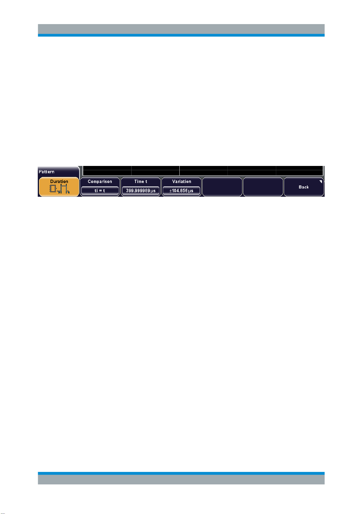
R&S®RTM2000
Triggers
Reference for Triggers
Remote command:
TRIGger:A:PATTern:FUNCtion on page 455
Trigger On
Sets the trigger point depending on the result of the logical combination of the channel
states.
Remote command:
TRIGger:A:PATTern:CONDition on page 455
Time Limitation
In addition to the pattern and the trigger levels, you can define a timing condition - how
long the result of the pattern condition must be true or false.
Duration
Enables or disables the time limitation to the pattern state.
Remote command:
TRIGger:A:PATTern:MODE on page 456
Comparison
Sets how the duration time of the resulting pattern state is compared with the given
time limit(s).
"ti<t, ti>t"
"ti=t"
"ti≠t"
"Inside, Outside"
"Timeout"
Remote command:
TRIGger:A:PATTern:WIDTh:RANGe on page 456
TRIGger:A:PATTern:MODE on page 456
Triggers if the pattern state changes before or after the "Time t" has
expired.
Triggers if the pattern state changes exactly at "Time t" if "Variation"
Δt = 0.
If "Variation" ≠ 0: this setting triggers within the range t±Δt.
Triggers on pattern state durations unequal to the "Time t", if "Variation" Δt = 0.
If "Variation" ≠ 0: this setting triggers outside a range t±Δt.
Triggers on pattern state durations inside or outside a range specified
with "Time t1" and "Time t2".
This method is an alternative setting to the range definition with "Time
t" and "Variation". The values are interdependent. "Variation" and
"Time t" are adjusted if you change t1 and t2, and vice versa.
Defines how long the result of the pattern condition must be true. The
instrument triggers at "Time t".
68User Manual 1317.4726.02 ─ 10

R&S®RTM2000
Triggers
Reference for Triggers
Time t
Sets the reference time, the nominal value for comparisons ti<t, ti>t, ti=t, ti≠t and timeout
Remote command:
TRIGger:A:PATTern:WIDTh[:WIDTh] on page 456
Time t1, Time t2
Set the lower and upper time limits defining the time range if "Inside" or "Outside" is set
for comparison. "Time t" and "Variation" are adjusted accordingly.
Variation
Sets a range Δt to the reference "Time t", if comparison is set to "ti=t" or "ti≠t". The
instrument triggers on pulses inside or outside the range ti±Δt.
Remote command:
TRIGger:A:PATTern:WIDTh:DELTa on page 457
3.3.2.7 Runt
A runt is a pulse lower than normal in amplitude. The amplitude crosses the first
threshold twice in succession without crossing the second one. For example, this trigger can detect logic, digital, and analog signals remaining below a specified threshold
amplitude because I/O ports are in undefined state.
Polarity
Sets the polarity of a pulse, that is the direction of the first pulse slope.
"Positive"
"Negative"
Remote command:
TRIGger:A:RUNT:POLarity on page 457
Upper Level
Sets the upper trigger level.
To set the value using the Level 50% rotary knob, press the knob to toggle upper and
lower level and then turn the knob.
Remote command:
TRIGger:A:LEVel<n>:RUNT:UPPer on page 457
Positive going pulse, the width is defined from the rising to the falling
slopes.
Negative going pulse, the width is defined from the falling to the rising
slopes.
Lower Level
Sets the lower trigger level.
The value corresponds to the threshold value of the trigger channel.
69User Manual 1317.4726.02 ─ 10
 Loading...