

Page 1

R&S®RTB2000
Digital Oscilloscope
User Manual
(=Q@;2)
1333.1611.02 ─ 03
User Manual
Page 2

This manual describes the following R&S®RTB2000 models:
●
R&S®RTB2002 (1333.1005K02)
●
R&S®RTB2004 (1333.1005K04)
© 2017 Rohde & Schwarz GmbH & Co. KG
Mühldorfstr. 15, 81671 München, Germany
Phone: +49 89 41 29 - 0
Fax: +49 89 41 29 12 164
Email: info@rohde-schwarz.com
Internet: www.rohde-schwarz.com
Subject to change – Data without tolerance limits is not binding.
R&S® is a registered trademark of Rohde & Schwarz GmbH & Co. KG.
Trade names are trademarks of their owners.
Throughout this manual, products from Rohde & Schwarz are indicated without the ® symbol, e.g. R&S®RTB is indicated as
R&S RTB2000.
Page 3

Basic Safety Instructions
Symbol
Meaning
Symbol
Meaning
Notice, general danger location
Observe product documentation
ON/OFF Power
Caution when handling heavy equipment
Standby indication
Danger of electric shock
Direct current (DC)
Always read through and comply with the following safety instructions!
All plants and locations of the Rohde & Schwarz group of companies make every effort to keep the safety
standards of our products up to date and to offer our customers the highest possible degree of safety. Our
products and the auxiliary equipment they require are designed, built and tested in accordance with the
safety standards that apply in each case. Compliance with these standards is continuously monitored by
our quality assurance system. The product described here has been designed, built and tested in
accordance with the EC Certificate of Conformity and has left the manufacturer’s plant in a condition fully
complying with safety standards. To maintain this condition and to ensure safe operation, you must
observe all instructions and warnings provided in this manual. If you have any questions regarding these
safety instructions, the Rohde & Schwarz group of companies will be happy to answer them.
Furthermore, it is your responsibility to use the product in an appropriate manner. This product is designed
for use solely in industrial and laboratory environments or, if expressly permitted, also in the field and must
not be used in any way that may cause personal injury or property damage. You are responsible if the
product is used for any purpose other than its designated purpose or in disregard of the manufacturer's
instructions. The manufacturer shall assume no responsibility for such use of the product.
The product is used for its designated purpose if it is used in accordance with its product documentation
and within its performance limits (see data sheet, documentation, the following safety instructions). Using
the product requires technical skills and, in some cases, a basic knowledge of English. It is therefore
essential that only skilled and specialized staff or thoroughly trained personnel with the required skills be
allowed to use the product. If personal safety gear is required for using Rohde & Schwarz products, this
will be indicated at the appropriate place in the product documentation. Keep the basic safety instructions
and the product documentation in a safe place and pass them on to the subsequent users.
Observing the safety instructions will help prevent personal injury or damage of any kind caused by
dangerous situations. Therefore, carefully read through and adhere to the following safety instructions
before and when using the product. It is also absolutely essential to observe the additional safety
instructions on personal safety, for example, that appear in relevant parts of the product documentation. In
these safety instructions, the word "product" refers to all merchandise sold and distributed by the Rohde &
Schwarz group of companies, including instruments, systems and all accessories. For product-specific
information, see the data sheet and the product documentation.
Safety labels on products
The following safety labels are used on products to warn against risks and dangers.
1171.0000.42 - 09 Page 1
Page 4

Basic Safety Instructions
Symbol
Meaning
Symbol
Meaning
Caution ! Hot surface
Alternating current (AC)
Protective conductor terminal
To identify any terminal which is intended for
connection to an external conductor for
protection against electric shock in case of a
fault, or the terminal of a protective earth
Direct/alternating current (DC/AC)
Earth (Ground)
Class II Equipment
to identify equipment meeting the safety
requirements specified for Class II equipment
(device protected by double or reinforced
insulation)
Frame or chassis Ground terminal
EU labeling for batteries and accumulators
For additional information, see section "Waste
disposal/Environmental protection", item 1.
Be careful when handling electrostatic sensitive
devices
EU labeling for separate collection of electrical
and electronic devices
For additional information, see section "Waste
disposal/Environmental protection", item 2.
Warning! Laser radiation
For additional information, see section
"Operation", item 7.
Indicates a hazardous situation which, if not avoided, will result in death or
serious injury.
Indicates a hazardous situation which, if not avoided, could result in death or
serious injury.
Indicates a hazardous situation which, if not avoided, could result in minor or
moderate injury.
Indicates information considered important, but not hazard-related, e.g.
messages relating to property damage.
In the product documentation, the word ATTENTION is used synonymously.
Signal words and their meaning
The following signal words are used in the product documentation in order to warn the reader about risks
and dangers.
These signal words are in accordance with the standard definition for civil applications in the European
Economic Area. Definitions that deviate from the standard definition may also exist in other economic
areas or military applications. It is therefore essential to make sure that the signal words described here
are always used only in connection with the related product documentation and the related product. The
use of signal words in connection with unrelated products or documentation can result in misinterpretation
and in personal injury or material damage.
1171.0000.42 - 09 Page 2
Page 5

Basic Safety Instructions
Operating states and operating positions
The product may be operated only under the operating conditions and in the positions specified by the
manufacturer, without the product's ventilation being obstructed. If the manufacturer's specifications are
not observed, this can result in electric shock, fire and/or serious personal injury or death. Applicable local
or national safety regulations and rules for the prevention of accidents must be observed in all work
performed.
1. Unless otherwise specified, the following requirements apply to Rohde & Schwarz products:
predefined operating position is always with the housing floor facing down, IP protection 2X, use only
indoors, max. operating altitude 2000 m above sea level, max. transport altitude 4500 m above sea
level. A tolerance of ±10 % shall apply to the nominal voltage and ±5 % to the nominal frequency,
overvoltage category 2, pollution degree 2.
2. Do not place the product on surfaces, vehicles, cabinets or tables that for reasons of weight or stability
are unsuitable for this purpose. Always follow the manufacturer's installation instructions when
installing the product and fastening it to objects or structures (e.g. walls and shelves). An installation
that is not carried out as described in the product documentation could result in personal injury or
even death.
3. Do not place the product on heat-generating devices such as radiators or fan heaters. The ambient
temperature must not exceed the maximum temperature specified in the product documentation or in
the data sheet. Product overheating can cause electric shock, fire and/or serious personal injury or
even death.
Electrical safety
If the information on electrical safety is not observed either at all or to the extent necessary, electric shock,
fire and/or serious personal injury or death may occur.
1. Prior to switching on the product, always ensure that the nominal voltage setting on the product
matches the nominal voltage of the mains-supply network. If a different voltage is to be set, the power
fuse of the product may have to be changed accordingly.
2. In the case of products of safety class I with movable power cord and connector, operation is
permitted only on sockets with a protective conductor contact and protective conductor.
3. Intentionally breaking the protective conductor either in the feed line or in the product itself is not
permitted. Doing so can result in the danger of an electric shock from the product. If extension cords
or connector strips are implemented, they must be checked on a regular basis to ensure that they are
safe to use.
4. If there is no power switch for disconnecting the product from the mains, or if the power switch is not
suitable for this purpose, use the plug of the connecting cable to disconnect the product from the
mains. In such cases, always ensure that the power plug is easily reachable and accessible at all
times. For example, if the power plug is the disconnecting device, the length of the connecting cable
must not exceed 3 m. Functional or electronic switches are not suitable for providing disconnection
from the AC supply network. If products without power switches are integrated into racks or systems,
the disconnecting device must be provided at the system level.
5. Never use the product if the power cable is damaged. Check the power cables on a regular basis to
ensure that they are in proper operating condition. By taking appropriate safety measures and
carefully laying the power cable, ensure that the cable cannot be damaged and that no one can be
hurt by, for example, tripping over the cable or suffering an electric shock.
1171.0000.42 - 09 Page 3
Page 6

Basic Safety Instructions
6. The product may be operated only from TN/TT supply networks fuse-protected with max. 16 A (higher
fuse only after consulting with the Rohde & Schwarz group of companies).
7. Do not insert the plug into sockets that are dusty or dirty. Insert the plug firmly and all the way into the
socket provided for this purpose. Otherwise, sparks that result in fire and/or injuries may occur.
8. Do not overload any sockets, extension cords or connector strips; doing so can cause fire or electric
shocks.
9. For measurements in circuits with voltages V
> 30 V, suitable measures (e.g. appropriate
rms
measuring equipment, fuse protection, current limiting, electrical separation, insulation) should be
taken to avoid any hazards.
10. Ensure that the connections with information technology equipment, e.g. PCs or other industrial
computers, comply with the IEC 60950-1 / EN 60950-1 or IEC 61010-1 / EN 61010-1 standards that
apply in each case.
11. Unless expressly permitted, never remove the cover or any part of the housing while the product is in
operation. Doing so will expose circuits and components and can lead to injuries, fire or damage to the
product.
12. If a product is to be permanently installed, the connection between the protective conductor terminal
on site and the product's protective conductor must be made first before any other connection is
made. The product may be installed and connected only by a licensed electrician.
13. For permanently installed equipment without built-in fuses, circuit breakers or similar protective
devices, the supply circuit must be fuse-protected in such a way that anyone who has access to the
product, as well as the product itself, is adequately protected from injury or damage.
14. Use suitable overvoltage protection to ensure that no overvoltage (such as that caused by a bolt of
lightning) can reach the product. Otherwise, the person operating the product will be exposed to the
danger of an electric shock.
15. Any object that is not designed to be placed in the openings of the housing must not be used for this
purpose. Doing so can cause short circuits inside the product and/or electric shocks, fire or injuries.
16. Unless specified otherwise, products are not liquid-proof (see also section "Operating states and
operating positions", item 1). Therefore, the equipment must be protected against penetration by
liquids. If the necessary precautions are not taken, the user may suffer electric shock or the product
itself may be damaged, which can also lead to personal injury.
17. Never use the product under conditions in which condensation has formed or can form in or on the
product, e.g. if the product has been moved from a cold to a warm environment. Penetration by water
increases the risk of electric shock.
18. Prior to cleaning the product, disconnect it completely from the power supply (e.g. AC supply network
or battery). Use a soft, non-linting cloth to clean the product. Never use chemical cleaning agents such
as alcohol, acetone or diluents for cellulose lacquers.
Operation
1. Operating the products requires special training and intense concentration. Make sure that persons
who use the products are physically, mentally and emotionally fit enough to do so; otherwise, injuries
or material damage may occur. It is the responsibility of the employer/operator to select suitable
personnel for operating the products.
1171.0000.42 - 09 Page 4
Page 7

Basic Safety Instructions
2. Before you move or transport the product, read and observe the section titled "Transport".
3. As with all industrially manufactured goods, the use of substances that induce an allergic reaction
(allergens) such as nickel cannot be generally excluded. If you develop an allergic reaction (such as a
skin rash, frequent sneezing, red eyes or respiratory difficulties) when using a Rohde & Schwarz
product, consult a physician immediately to determine the cause and to prevent health problems or
stress.
4. Before you start processing the product mechanically and/or thermally, or before you take it apart, be
sure to read and pay special attention to the section titled "Waste disposal/Environmental protection",
item 1.
5. Depending on the function, certain products such as RF radio equipment can produce an elevated
level of electromagnetic radiation. Considering that unborn babies require increased protection,
pregnant women must be protected by appropriate measures. Persons with pacemakers may also be
exposed to risks from electromagnetic radiation. The employer/operator must evaluate workplaces
where there is a special risk of exposure to radiation and, if necessary, take measures to avert the
potential danger.
6. Should a fire occur, the product may release hazardous substances (gases, fluids, etc.) that can
cause health problems. Therefore, suitable measures must be taken, e.g. protective masks and
protective clothing must be worn.
7. Laser products are given warning labels that are standardized according to their laser class. Lasers
can cause biological harm due to the properties of their radiation and due to their extremely
concentrated electromagnetic power. If a laser product (e.g. a CD/DVD drive) is integrated into a
Rohde & Schwarz product, absolutely no other settings or functions may be used as described in the
product documentation. The objective is to prevent personal injury (e.g. due to laser beams).
8. EMC classes (in line with EN 55011/CISPR 11, and analogously with EN 55022/CISPR 22,
EN 55032/CISPR 32)
Class A equipment:
Equipment suitable for use in all environments except residential environments and environments
that are directly connected to a low-voltage supply network that supplies residential buildings
Note: Class A equipment is intended for use in an industrial environment. This equipment may
cause radio disturbances in residential environments, due to possible conducted as well as
radiated disturbances. In this case, the operator may be required to take appropriate measures to
eliminate these disturbances.
Class B equipment:
Equipment suitable for use in residential environments and environments that are directly
connected to a low-voltage supply network that supplies residential buildings
Repair and service
1. The product may be opened only by authorized, specially trained personnel. Before any work is
performed on the product or before the product is opened, it must be disconnected from the AC supply
network. Otherwise, personnel will be exposed to the risk of an electric shock.
1171.0000.42 - 09 Page 5
Page 8

Basic Safety Instructions
2. Adjustments, replacement of parts, maintenance and repair may be performed only by electrical
experts authorized by Rohde & Schwarz. Only original parts may be used for replacing parts relevant
to safety (e.g. power switches, power transformers, fuses). A safety test must always be performed
after parts relevant to safety have been replaced (visual inspection, protective conductor test,
insulation resistance measurement, leakage current measurement, functional test). This helps ensure
the continued safety of the product.
Batteries and rechargeable batteries/cells
If the information regarding batteries and rechargeable batteries/cells is not observed either at all or to the
extent necessary, product users may be exposed to the risk of explosions, fire and/or serious personal
injury, and, in some cases, death. Batteries and rechargeable batteries with alkaline electrolytes (e.g.
lithium cells) must be handled in accordance with the EN 62133 standard.
1. Cells must not be taken apart or crushed.
2. Cells or batteries must not be exposed to heat or fire. Storage in direct sunlight must be avoided.
Keep cells and batteries clean and dry. Clean soiled connectors using a dry, clean cloth.
3. Cells or batteries must not be short-circuited. Cells or batteries must not be stored in a box or in a
drawer where they can short-circuit each other, or where they can be short-circuited by other
conductive materials. Cells and batteries must not be removed from their original packaging until they
are ready to be used.
4. Cells and batteries must not be exposed to any mechanical shocks that are stronger than permitted.
5. If a cell develops a leak, the fluid must not be allowed to come into contact with the skin or eyes. If
contact occurs, wash the affected area with plenty of water and seek medical aid.
6. Improperly replacing or charging cells or batteries that contain alkaline electrolytes (e.g. lithium cells)
can cause explosions. Replace cells or batteries only with the matching Rohde & Schwarz type (see
parts list) in order to ensure the safety of the product.
7. Cells and batteries must be recycled and kept separate from residual waste. Rechargeable batteries
and normal batteries that contain lead, mercury or cadmium are hazardous waste. Observe the
national regulations regarding waste disposal and recycling.
8. Follow the transport stipulations of the carrier (IATA-DGR, IMDG-Code, ADR, RID) when returning
lithium batteries to Rohde & Schwarz subsidiaries.
Transport
1. The product may be very heavy. Therefore, the product must be handled with care. In some cases,
the user may require a suitable means of lifting or moving the product (e.g. with a lift-truck) to avoid
back or other physical injuries.
2. Handles on the products are designed exclusively to enable personnel to transport the product. It is
therefore not permissible to use handles to fasten the product to or on transport equipment such as
cranes, fork lifts, wagons, etc. The user is responsible for securely fastening the products to or on the
means of transport or lifting. Observe the safety regulations of the manufacturer of the means of
transport or lifting. Noncompliance can result in personal injury or material damage.
1171.0000.42 - 09 Page 6
Page 9

Instrucciones de seguridad elementales
3. If you use the product in a vehicle, it is the sole responsibility of the driver to drive the vehicle safely
and properly. The manufacturer assumes no responsibility for accidents or collisions. Never use the
product in a moving vehicle if doing so could distract the driver of the vehicle. Adequately secure the
product in the vehicle to prevent injuries or other damage in the event of an accident.
Waste disposal/Environmental protection
1. Specially marked equipment has a battery or accumulator that must not be disposed of with unsorted
municipal waste, but must be collected separately. It may only be disposed of at a suitable collection
point or via a Rohde & Schwarz customer service center.
2. Waste electrical and electronic equipment must not be disposed of with unsorted municipal waste, but
must be collected separately.
Rohde & Schwarz GmbH & Co. KG has developed a disposal concept and takes full responsibility for
take-back obligations and disposal obligations for manufacturers within the EU. Contact your
Rohde & Schwarz customer service center for environmentally responsible disposal of the product.
3. If products or their components are mechanically and/or thermally processed in a manner that goes
beyond their intended use, hazardous substances (heavy-metal dust such as lead, beryllium, nickel)
may be released. For this reason, the product may only be disassembled by specially trained
personnel. Improper disassembly may be hazardous to your health. National waste disposal
regulations must be observed.
4. If handling the product releases hazardous substances or fuels that must be disposed of in a special
way, e.g. coolants or engine oils that must be replenished regularly, the safety instructions of the
manufacturer of the hazardous substances or fuels and the applicable regional waste disposal
regulations must be observed. Also observe the relevant safety instructions in the product
documentation. The improper disposal of hazardous substances or fuels can cause health problems
and lead to environmental damage.
For additional information about environmental protection, visit the Rohde & Schwarz website.
1171.0000.42 - 09 Page 7
Page 10

Customer Support
Technical support – where and when you need it
For quick, expert help with any Rohde & Schwarz equipment, contact one of our Customer Support
Centers. A team of highly qualified engineers provides telephone support and will work with you to find a
solution to your query on any aspect of the operation, programming or applications of Rohde & Schwarz
equipment.
Up-to-date information and upgrades
To keep your instrument up-to-date and to be informed about new application notes related to your
instrument, please send an e-mail to the Customer Support Center stating your instrument and your wish.
We will take care that you will get the right information.
Europe, Africa, Middle East
North America
Latin America
Asia/Pacific
China
Phone +49 89 4129 12345
customersupport@rohde-schwarz.com
Phone 1-888-TEST-RSA (1-888-837-8772)
customer.support@rsa.rohde-schwarz.com
Phone +1-410-910-7988
customersupport.la@rohde-schwarz.com
Phone +65 65 13 04 88
customersupport.asia@rohde-schwarz.com
Phone +86-800-810-8228 /
+86-400-650-5896
customersupport.china@rohde-schwarz.com
1171.0200.22-06.00
Page 11

R&S®RTB2000
1.1 For Your Safety........................................................................................................... 13
1.2 Documentation Overview........................................................................................... 14
1.2.1 Manuals and Instrument Help....................................................................................... 14
1.2.2 Data Sheet and Brochure..............................................................................................15
1.2.3 Calibration Certificate....................................................................................................15
1.2.4 Release Notes and Open Source Acknowledgment..................................................... 16
1.3 Conventions Used in the Documentation.................................................................16
1.3.1 Typographical Conventions...........................................................................................16
1.3.2 Conventions for Procedure Descriptions.......................................................................16
1.3.3 Notes on Screenshots...................................................................................................17
Contents
Contents
1 Preface.................................................................................................. 13
2 Getting Started..................................................................................... 18
2.1 Preparing for Use........................................................................................................ 18
2.1.1 Unpacking and Checking the Instrument...................................................................... 18
2.1.2 Positioning the Instrument.............................................................................................18
2.1.3 Starting the Instrument..................................................................................................19
2.1.4 Replacing the Fuses..................................................................................................... 21
2.2 Instrument Tour...........................................................................................................22
2.2.1 Front Panel....................................................................................................................22
2.2.2 Rear Panel.................................................................................................................... 24
3 Operating Basics..................................................................................26
3.1 Display Overview........................................................................................................ 26
3.2 Selecting the Application........................................................................................... 27
3.3 Using the Touchscreen.............................................................................................. 27
3.3.1 Accessing Functionality Using the Main Menu..............................................................27
3.3.2 Accessing Functionality Using Shortcuts...................................................................... 29
3.3.3 Entering Data................................................................................................................ 29
3.3.4 Using Gestures............................................................................................................. 30
3.4 Front Panel Keys.........................................................................................................31
3.4.1 Action Controls..............................................................................................................31
3.4.2 Analysis Controls.......................................................................................................... 32
3User Manual 1333.1611.02 ─ 03
Page 12

R&S®RTB2000
3.5 Using the Toolbar........................................................................................................33
3.6 Getting Help.................................................................................................................34
4.1 Connecting Probes and Displaying a Signal............................................................36
4.2 Vertical Setup.............................................................................................................. 37
4.2.1 VERTICAL Controls...................................................................................................... 38
4.2.2 Short Menu for Analog Channels.................................................................................. 39
4.2.3 Vertical Settings............................................................................................................ 40
4.2.4 Probe Settings...............................................................................................................43
4.2.5 Threshold Settings........................................................................................................ 44
4.2.6 Label Settings............................................................................................................... 45
4.3 Horizontal Setup..........................................................................................................45
Contents
4 Waveform Setup...................................................................................36
4.3.1 HORIZONTAL Controls.................................................................................................46
4.3.2 Shortcuts for Horizontal Settings...................................................................................47
4.3.3 Horizontal Settings........................................................................................................ 48
4.4 Acquisition Setup........................................................................................................49
4.4.1 Shortcuts for Acquisition Settings................................................................................. 49
4.4.2 Acquisition Settings.......................................................................................................50
5 Trigger...................................................................................................53
5.1 Trigger Controls.......................................................................................................... 53
5.2 Shortcuts for Trigger Settings................................................................................... 55
5.3 General Trigger Settings............................................................................................ 56
5.4 Edge Trigger................................................................................................................ 58
5.5 Width Trigger...............................................................................................................59
5.6 Video Trigger............................................................................................................... 62
5.7 Pattern Trigger............................................................................................................ 64
5.8 Timeout Trigger...........................................................................................................66
6 Waveform Analysis..............................................................................69
6.1 Zoom............................................................................................................................ 69
6.1.1 Using the Zoom.............................................................................................................69
6.1.2 Zoom Settings............................................................................................................... 71
6.2 Mathematics................................................................................................................ 71
4User Manual 1333.1611.02 ─ 03
Page 13

R&S®RTB2000
6.2.1 Math Waveform Settings...............................................................................................72
6.3 Reference Waveforms................................................................................................ 74
6.3.1 Using References..........................................................................................................74
6.3.2 Settings for Reference Waveforms............................................................................... 76
6.4 History and Segmented Memory (Option R&S RTB-K15)....................................... 78
6.4.1 Segmented Memory......................................................................................................78
6.4.2 Segment Table..............................................................................................................79
6.4.3 Displaying History Segments........................................................................................ 80
6.4.4 Exporting History Data.................................................................................................. 81
6.5 Search.......................................................................................................................... 84
6.5.1 Search Conditions and Results.....................................................................................84
6.5.2 General Search Settings............................................................................................... 87
6.5.3 Edge Search................................................................................................................. 89
Contents
6.5.4 Width Search.................................................................................................................90
6.5.5 Peak Search..................................................................................................................91
6.5.6 Rise/Fall Time Search...................................................................................................91
6.5.7 Runt Setup.................................................................................................................... 93
6.5.8 Data2Clock....................................................................................................................94
6.5.9 Pattern Search.............................................................................................................. 96
7 Measurements......................................................................................99
7.1 Quick Measurements.................................................................................................. 99
7.2 Automatic Measurements........................................................................................ 100
7.2.1 Measurement Results................................................................................................. 100
7.2.2 Measurement Types................................................................................................... 101
7.2.3 Settings for Automatic Measurements........................................................................ 105
7.3 Cursor Measurements.............................................................................................. 107
7.3.1 Cursor Settings........................................................................................................... 109
8 Applications........................................................................................112
8.1 Mask Testing............................................................................................................. 112
8.1.1 About Masks and Mask Testing.................................................................................. 112
8.1.2 Using Masks................................................................................................................113
8.1.3 Mask Window..............................................................................................................115
8.1.4 Mask Menu..................................................................................................................116
5User Manual 1333.1611.02 ─ 03
Page 14

R&S®RTB2000
8.2 FFT Analysis..............................................................................................................118
8.2.1 FFT Display.................................................................................................................119
8.2.2 Performing FFT Analysis.............................................................................................120
8.2.3 FFT Setup................................................................................................................... 120
8.3 XY-Diagram................................................................................................................124
8.4 Digital Voltmeter........................................................................................................126
8.4.1 Using the Meter...........................................................................................................126
8.4.2 Meter Settings............................................................................................................. 127
8.5 Trigger Counter......................................................................................................... 128
9.1 Saving and Loading Instrument Settings............................................................... 131
9.2 Exporting Waveforms............................................................................................... 132
Contents
9 Documenting Results........................................................................ 130
9.2.1 Waveform Export Settings.......................................................................................... 133
9.2.2 Waveform File Formats...............................................................................................134
9.3 Annotations............................................................................................................... 136
9.4 Screenshots...............................................................................................................137
9.5 Quick Save with OneTouch......................................................................................139
9.6 Export and Import..................................................................................................... 140
10 General Instrument Setup................................................................. 142
10.1 Instrument Settings.................................................................................................. 142
10.2 Display Settings........................................................................................................ 145
10.3 Resetting the Instrument..........................................................................................148
10.4 Locking the Touchscreen.........................................................................................148
10.5 Performing a Self-Alignment....................................................................................148
10.6 Setting the Data, Time and Language..................................................................... 149
10.7 Adjusting Passive Probes........................................................................................ 150
10.8 Options.......................................................................................................................151
10.8.1 Activating Options....................................................................................................... 152
10.9 Updating the Firmware............................................................................................. 152
11 Network Connections and Remote Operation.................................154
11.1 LAN Connection........................................................................................................ 154
11.2 USB Connection........................................................................................................156
6User Manual 1333.1611.02 ─ 03
Page 15

R&S®RTB2000
11.3 Remote Access Using a Web Browser................................................................... 158
11.3.1 Accessing the Instrument Using a Web Browser........................................................ 158
11.3.2 Instrument Home.........................................................................................................158
11.3.3 Screenshot.................................................................................................................. 159
11.3.4 SCPI Device Control................................................................................................... 160
11.3.5 Save/Recall................................................................................................................. 161
11.3.6 Network Settings......................................................................................................... 162
11.3.7 Change Password.......................................................................................................163
11.3.8 Livescreen...................................................................................................................163
11.3.9 Remote Front Panel.................................................................................................... 163
12 Serial Bus Analysis............................................................................164
12.1 Basics of Protocol Analysis.....................................................................................164
Contents
12.1.1 Protocol - Common Settings....................................................................................... 165
12.1.2 Display Settings.......................................................................................................... 167
12.1.3 Bus Table: Decode Results.........................................................................................167
12.1.4 Bus Labels.................................................................................................................. 168
12.1.5 Label List.....................................................................................................................169
12.2 SPI/SSPI Bus (Option R&S RTB-K1)........................................................................172
12.2.1 The SPI Protocol......................................................................................................... 172
12.2.2 SPI/SSPI Configuration...............................................................................................173
12.2.3 SPI/SSPI Trigger.........................................................................................................176
12.2.4 SPI/SSPI Decode Results ..........................................................................................178
12.3 I²C (Option R&S RTB-K1)..........................................................................................179
12.3.1 The I²C Protocol.......................................................................................................... 180
12.3.2
12.3.3
12.3.4
I2C Configuration.........................................................................................................182
I2C Trigger...................................................................................................................183
I2C Decode Results ....................................................................................................186
12.3.5
12.4 UART / RS232 (Option R&S RTB-K2)...................................................................... 188
12.4.1 The UART / RS232 Interface...................................................................................... 189
12.4.2 UART Configuration.................................................................................................... 189
12.4.3 UART Trigger.............................................................................................................. 191
12.4.4 UART Decode Results ............................................................................................... 194
I2C Label List...............................................................................................................187
7User Manual 1333.1611.02 ─ 03
Page 16

R&S®RTB2000
12.5 CAN (Option R&S RTB-K3).......................................................................................195
12.5.1 CAN Configuration...................................................................................................... 195
12.5.2 CAN Trigger................................................................................................................ 197
12.5.3 CAN Decode Results.................................................................................................. 201
12.5.4 Search on Decoded CAN Data................................................................................... 203
12.5.5 CAN Label List............................................................................................................ 205
12.6 LIN (Option R&S RTB-K3).........................................................................................207
12.6.1 The LIN Protocol......................................................................................................... 207
12.6.2 LIN Configuration........................................................................................................ 209
12.6.3 LIN Trigger.................................................................................................................. 210
12.6.4 LIN Decode Results ................................................................................................... 214
12.6.5 Search on Decoded LIN Data..................................................................................... 215
12.6.6 LIN Label List.............................................................................................................. 217
Contents
13 Logic Analyzer (Option R&S RTB-B1, MSO)....................................220
13.1 Short Menu for Logic Channels...............................................................................220
13.2 Logic Analyzer Settings........................................................................................... 221
13.3 Triggering on Logic Channels................................................................................. 223
13.4 Analyzing Logic Channels....................................................................................... 223
13.5 Parallel Buses............................................................................................................224
13.5.1 Parallel Bus Configuration...........................................................................................224
13.5.2 Decode Results...........................................................................................................226
14 Signal Generation (Option R&S RTB-B6).........................................228
14.1 Function Generator...................................................................................................228
14.1.1 Basic Function Generator Settings............................................................................. 229
14.1.2 Sweep Settings........................................................................................................... 231
14.1.3 Modulation Settings.....................................................................................................232
14.1.4 Arbitrary Setup Settings.............................................................................................. 233
14.2 Pattern Generator......................................................................................................234
14.2.1 Pattern Selection.........................................................................................................234
14.2.2 Settings for Square Wave Pattern...............................................................................235
14.2.3 Settings for Counter Pattern........................................................................................236
14.2.4 Settings for Arbitrary Pattern.......................................................................................236
14.2.5 Settings for Manual Pattern.........................................................................................239
8User Manual 1333.1611.02 ─ 03
Page 17

R&S®RTB2000
14.2.6 Settings for Serial Buses.............................................................................................239
15 Remote Control Commands..............................................................240
15.1 Conventions used in Command Description......................................................... 240
15.2 Programming Examples........................................................................................... 241
15.2.1 Documenting Results.................................................................................................. 241
15.2.2 Firmware Update.........................................................................................................245
15.2.3 Search.........................................................................................................................246
15.2.4 Function Generator..................................................................................................... 247
15.3 Common Commands................................................................................................ 247
15.4 Waveform Setup........................................................................................................250
15.4.1 Automatic Setup..........................................................................................................250
15.4.2 Starting and Stopping Acquisition............................................................................... 250
Contents
15.4.3 Vertical Settings.......................................................................................................... 252
15.4.4 Probes.........................................................................................................................258
15.4.5 Horizontal Settings...................................................................................................... 258
15.4.6 Acquisition Settings.....................................................................................................260
15.4.7 Waveform Data........................................................................................................... 265
15.5 Trigger........................................................................................................................266
15.5.1 General Trigger Settings............................................................................................. 266
15.5.2 Edge Trigger............................................................................................................... 268
15.5.3 Width Trigger...............................................................................................................269
15.5.4 Video/TV Trigger......................................................................................................... 271
15.5.5 Pattern Trigger............................................................................................................ 272
15.5.6 Timeout Trigger...........................................................................................................275
15.6 Waveform Analysis................................................................................................... 276
15.6.1 Zoom........................................................................................................................... 276
15.6.2 Mathematics................................................................................................................277
15.6.3 Reference Waveforms................................................................................................ 278
15.6.4 Search.........................................................................................................................281
15.6.5 History (Option R&S RTB2000-K15)...........................................................................296
15.7 Measurements........................................................................................................... 306
15.7.1 Quick Measurements.................................................................................................. 306
15.7.2 Automatic Measurements........................................................................................... 307
9User Manual 1333.1611.02 ─ 03
Page 18

R&S®RTB2000
15.7.3 Cursor Measurements.................................................................................................317
15.8 Applications...............................................................................................................323
15.8.1 Mask Testing...............................................................................................................323
15.8.2 FFT Analysis............................................................................................................... 327
15.8.3 XY-Waveforms............................................................................................................ 334
15.8.4 Digital Voltmeter..........................................................................................................335
15.8.5 Trigger Counter........................................................................................................... 337
15.9 Documenting Results............................................................................................... 338
15.9.1 Transfer of Waveform Data.........................................................................................338
15.9.2 Waveform Data Export to File..................................................................................... 349
15.9.3 Screenshots................................................................................................................ 350
15.9.4 Instrument Settings: Mass MEMomory Subsystem.................................................... 352
15.10 General Instrument Setup........................................................................................ 359
Contents
15.10.1 Display Settings.......................................................................................................... 359
15.10.2 System Settings.......................................................................................................... 363
15.10.3 LAN Settings............................................................................................................... 367
15.10.4 USB Settings...............................................................................................................369
15.10.5 Trigger Out.................................................................................................................. 369
15.11 Serial Bus Analysis...................................................................................................370
15.11.1 General....................................................................................................................... 371
15.11.2 SPI and SSPI (Option R&S RTB-K1).......................................................................... 373
15.11.3 I²C............................................................................................................................... 384
15.11.4 UART (Option R&S RTB-K2)...................................................................................... 395
15.11.5 CAN.............................................................................................................................402
15.11.6 LIN (Option R&S RTB-K3).......................................................................................... 418
15.12 Mixed Signal Option (Option R&S RTB-B1)............................................................431
15.12.1 Logic Channels........................................................................................................... 431
15.12.2 Parallel Buses............................................................................................................. 437
15.13 Signal Generation (Option R&S RTB-B6)................................................................442
15.13.1 Function Generator..................................................................................................... 442
15.13.2 Pattern Generator....................................................................................................... 448
15.14 Status Reporting....................................................................................................... 454
15.14.1 STATus:OPERation Register......................................................................................454
10User Manual 1333.1611.02 ─ 03
Page 19

R&S®RTB2000
15.14.2 STATus:QUEStionable Registers............................................................................... 456
16 Maintenance....................................................................................... 460
16.1 Cleaning..................................................................................................................... 460
16.2 Storing and Packing................................................................................................. 461
16.3 Replacing the Fuses................................................................................................. 461
16.4 Data Security............................................................................................................. 462
A SCPI Command Structure................................................................. 463
A.1 Syntax for Common Commands............................................................................. 463
A.2 Syntax for Device-Specific Commands.................................................................. 464
A.2.1 Long and short form.................................................................................................... 464
A.2.2 Numeric Suffixes......................................................................................................... 465
Contents
Annex.................................................................................................. 463
A.2.3 Optional Mnemonics................................................................................................... 465
A.3 SCPI Parameters....................................................................................................... 466
A.3.1 Numeric Values...........................................................................................................466
A.3.2 Special Numeric Values.............................................................................................. 467
A.3.3 Boolean Parameters................................................................................................... 467
A.3.4 Text Parameters..........................................................................................................467
A.3.5 Character Strings........................................................................................................ 468
A.3.6 Block Data...................................................................................................................468
A.4 Overview of Syntax Elements.................................................................................. 468
A.5 Structure of a Command Line..................................................................................469
A.6 Responses to Queries.............................................................................................. 470
B Command Sequence and Synchronization..................................... 472
B.1 Preventing Overlapping Execution......................................................................... 472
C Status Reporting System.................................................................. 474
C.1 Structure of a SCPI Status Register........................................................................ 474
C.2 Hierarchy of status registers................................................................................... 475
C.3 Contents of the Status Registers............................................................................ 477
C.3.1 Status Byte (STB) and Service Request Enable Register (SRE)................................477
C.3.2 Event Status Register (ESR) and Event Status Enable Register (ESE)..................... 478
C.3.3 STATus:OPERation Register......................................................................................479
11User Manual 1333.1611.02 ─ 03
Page 20

R&S®RTB2000
C.3.4 STATus:QUEStionable Register................................................................................. 479
C.4 Application of the Status Reporting System.......................................................... 482
C.4.1 Service Request..........................................................................................................482
C.4.2 Serial Poll.................................................................................................................... 483
C.4.3 Query of an instrument status..................................................................................... 483
C.4.4 Error Queue................................................................................................................ 484
C.5 Reset Values of the Status Reporting System....................................................... 484
Contents
List of Commands..............................................................................486
12User Manual 1333.1611.02 ─ 03
Page 21

R&S®RTB2000
1 Preface
Preface
For Your Safety
1.1 For Your Safety
The R&S RTB2000 digital oscilloscope is designed for measurements on circuits that
are only indirectly connected to the mains or not connected at all. It is not rated for any
measurement category.
The instrument is intended for use in industrial areas. When used in residential areas,
radio disturbances caused by the instrument can exceed given limits. Additional shielding can be required.
The instrument must be controlled by personnel familiar with the potential risks of measuring electrical quantities. Applicable local or national safety regulations and rules for
the prevention of accidents must be observed.
Safety information is part of the product documentation. It warns you about the potential dangers and gives instructions how to prevent personal injury or damage caused
by dangerous situations. Safety information is provided as follows:
●
The "Basic Safety Instructions" in different languages are delivered as a printed
brochure with the instrument.
●
Throughout the documentation, safety instructions are provided when you need to
take care during setup or operation.
Risk of injury
The instrument must be used in an appropriate manner to prevent electric shock, personal injury, fire, or damage:
●
Do not open the instrument casing.
●
Do not use the instrument if the instrument casing, the display or any accessory
are damaged. If you detect or suspect any damage, have the instrument or accessory inspected by qualified service personnel.
●
Do not operate the instrument in wet, damp or explosive atmospheres. Make sure
that the instrument, cables and connectors are completely dry before connecting
the inputs.
●
Do not exceed the voltage limits given in Chapter 2.2.1.1, "Input Connectors",
on page 23.
13User Manual 1333.1611.02 ─ 03
Page 22

R&S®RTB2000
Preface
Documentation Overview
Risk of instrument damage
An unsuitable operating site or test setup can damage the instrument and connected
devices. Ensure the following operating conditions before you switch on the instrument:
●
Read and observe the "Basic Safety Instructions" brochure and the safety instructions in the manuals.
●
Observe the operating conditions specified in the data sheet. Note that the general
safety instructions also contain information on operating conditions.
●
Position the instrument as described in the following sections.
Make sure that all fan openings are unobstructed and the airflow perforations are
unimpeded. The minimum distance from the wall is 10 cm.
●
Signal levels at the input connectors are all within the specified ranges.
●
Signal outputs are correctly connected and are not overloaded.
Instrument damage caused by electrostatic discharge
Electrostatic discharge (ESD) can damage the electronic components of the instrument
and the device under test (DUT). Electrostatic discharge is most likely to occur when
you connect or disconnect a DUT or test fixture to the instrument's test ports. To prevent electrostatic discharge, use a wrist strap and cord and connect yourself to the
ground, or use a conductive floor mat and heel strap combination.
Electromagnetic interference (EMI) may affect the measurement results.
To suppress generated electromagnetic interference (EMI):
●
Use suitable shielded cables of high quality. For example, use double-shielded RF
and LAN cables.
●
Always terminate open cable ends.
●
Note the EMC classification in the data sheet.
1.2 Documentation Overview
This section provides an overview of the R&S RTB2000 user documentation.
1.2.1 Manuals and Instrument Help
You find the manuals on the product page at:
www.rohde-schwarz.com/manual/rtb2000
14User Manual 1333.1611.02 ─ 03
Page 23

R&S®RTB2000
Preface
Documentation Overview
Getting started manual
Introduces the R&S RTB2000 and describes how to set up the product. A printed English version is included in the delivery.
User manual
Contains the description of all instrument modes and functions. It also provides an
introduction to remote control, a complete description of the remote control commands
with programming examples, and information on maintenance and instrument interfaces. Includes the contents of the getting started manual.
The online version of the user manual provides the complete contents for immediate
display on the internet.
Instrument help
The help offers quick, context-sensitive access to the functional description directly on
the instrument.
Basic safety instructions
Contains safety instructions, operating conditions and further important information.
The printed document is delivered with the instrument.
Instrument security procedures manual
Deals with security issues when working with the R&S RTB2000 in secure areas.
Service manual
Describes the performance test for checking the rated specifications, module replacement and repair, firmware update, troubleshooting and fault elimination, and contains
mechanical drawings and spare part lists. The service manual is available for registered users on the global Rohde & Schwarz information system (GLORIS, https://
gloris.rohde-schwarz.com).
1.2.2 Data Sheet and Brochure
The data sheet contains the technical specifications of the R&S RTB2000. It also lists
the options with their order numbers and optional accessories. The brochure provides
an overview of the instrument and deals with the specific characteristics.
See www.rohde-schwarz.com/brochure-datasheet/rtb2000
1.2.3 Calibration Certificate
The document is available on https://gloris.rohde-schwarz.com/calcert. You need the
device ID of your instrument, which you can find on a label on the rear panel.
15User Manual 1333.1611.02 ─ 03
Page 24

R&S®RTB2000
Preface
Conventions Used in the Documentation
1.2.4 Release Notes and Open Source Acknowledgment
The release notes list new features, improvements and known issues of the current
firmware version, and describe the firmware installation. The open source acknowledgment document provides verbatim license texts of the used open source software.
See www.rohde-schwarz.com/firmware/rtb2000. The open source acknowledgment
documant can also be read directly on the instrument.
1.3 Conventions Used in the Documentation
1.3.1 Typographical Conventions
The following text markers are used throughout this documentation:
Convention Description
"Graphical user interface elements"
All names of graphical user interface elements on the screen, such as
dialog boxes, menus, options, buttons, and softkeys are enclosed by
quotation marks.
KEYS Key names are written in capital letters.
File names, commands,
program code
Input Input to be entered by the user is displayed in italics.
Links Links that you can click are displayed in blue font.
"References" References to other parts of the documentation are enclosed by quota-
1.3.2 Conventions for Procedure Descriptions
File names, commands, coding samples and screen output are distinguished by their font.
tion marks.
When operating the instrument, several alternative methods may be available to perform the same task. In this case, the procedure using the touchscreen is described.
Any elements that can be activated by touching can also be clicked using an additionally connected mouse. The alternative procedure using the keys on the instrument or
the on-screen keyboard is only described if it deviates from the standard operating procedures.
The term "select" may refer to any of the described methods, i.e. using a finger on the
touchscreen, a mouse pointer in the display, or a key on the instrument or on a keyboard.
16User Manual 1333.1611.02 ─ 03
Page 25

R&S®RTB2000
Preface
Conventions Used in the Documentation
1.3.3 Notes on Screenshots
When describing the functions of the product, we use sample screenshots. These
screenshots are meant to illustrate as much as possible of the provided functions and
possible interdependencies between parameters. The shown values may not represent
realistic usage scenarios.
The screenshots usually show a fully equipped product, that is: with all options installed. Thus, some functions shown in the screenshots may not be available in your particular product configuration.
17User Manual 1333.1611.02 ─ 03
Page 26

R&S®RTB2000
2 Getting Started
Getting Started
Preparing for Use
2.1 Preparing for Use
2.1.1 Unpacking and Checking the Instrument
1. Inspect the package for damage.
If the packaging material shows any signs of stress, notify the carrier who delivered
the instrument.
2. Carefully unpack the instrument and the accessories.
3. Check the equipment for completeness. See section "Delivery contents"
on page 18.
4. Check the equipment for damage.
If there is damage, or anything is missing, immediately contact the carrier as well
as your distributor. Make sure not to discard the box and packing material.
Packing material
Retain the original packing material. If the instrument needs to be transported or shipped later, you can use the material to protect the control elements and connectors.
Delivery contents
The delivery package contains the following items:
●
R&S RTB2000 digital oscilloscope
●
R&S RT-ZP03 probes (2x for R&S RTB2002; 4x for R&S RTB2004)
●
Country-specific power cable
●
Printed "Getting Started" manual
●
Printed "Basic Safety Instructions" brochure
2.1.2 Positioning the Instrument
The instrument is designed for use under laboratory conditions. It can be used in
standalone operation on a bench top or can be installed in a rack.
For standalone operation, place the instrument on a horizontal bench with even, flat
surface. The instrument can be used in horizontal position, or with the support feet on
the bottom extended.
18User Manual 1333.1611.02 ─ 03
Page 27

R&S®RTB2000
Getting Started
Preparing for Use
The instrument can be installed in a 19" rack mount using a rack mount kit. The order
number of the rack mount kit is given in the data sheet. The installation instructions are
part of the rack mount kit.
Risk of injury if feet are folded out
The feet can fold in if they are not folded out completely or if the instrument is shifted.
This can cause damage or injury.
●
Fold the feet completely in or out to ensure stability of the instrument. Never shift
the instrument when the feet are folded out.
●
When the feet are folded out, do not work under the instrument or place anything
underneath.
●
The feet can break if they are overloaded. The overall load on the folded-out feet
must not exceed 200 N.
F
max
Risk of instrument damage due to overheating
An insufficient airflow can cause the R&S RTB2000 to overheat, which can impair the
measurement results, disturb the operation, and even cause damage.
●
Ensure that all fan openings are unobstructed and that the airflow perforations are
unimpeded. The minimum distance to a wall is 10 cm.
●
When placing several instruments side by side, keep a minimum distance of 20 cm
between the instruments. Ensure that the instruments do not draw in the preheated
air from their neighbors.
●
When mounting the instrument in a rack, observe the instructions of the rack manufacturer to ensure sufficient airflow and avoid overheating.
2.1.3 Starting the Instrument
2.1.3.1 Powering On
The R&S RTB2000 can be used with different AC power voltages and adapts itself
automatically to it.
19User Manual 1333.1611.02 ─ 03
Page 28

R&S®RTB2000
Getting Started
Preparing for Use
The nominal ranges are:
●
100 V to 240 V AC at 50 Hz to 60 Hz
●
0.95 A to 0.5 A
●
max. 60 W
Risk of injury
Connect the instrument only to an outlet that has a ground contact.
Do not use an isolating transformer to connect the instrument to the AC power supply.
1. Connect the power cable to the AC power connector on the rear panel of the
R&S RTB2000.
2. Connect the power cable to the socket outlet.
3. Switch the main power switch at the rear of the instrument to position I.
The STANDBY key lights up. The key is located in the bottom left corner of the
front panel.
You can leave the main power switch on to preserve your last instrument settings. To
disconnect from power supply, power off the instrument.
2.1.3.2 Starting Up and Shutting Down
To start up the instrument
1. Make sure that the R&S RTB2000 is connected to the AC power supply and the
main power switch on the rear panel is in position I.
2. Press the STANDBY key. The key is located in the bottom left corner of the front
panel.
The instrument performs a system check and starts the firmware. If the previous
session was terminated regularly, the oscilloscope uses the last settings.
Table 2-1: Colors of the STANDBY key
Green Instrument is on: firmware is working
Yellow Standby: instrument is off, main power switch is on
Warm-up and prepare the instrument
Make sure that the instrument has been running and warming up before you start the
self-alignment and the measurements. The minimum warm-up time is about 20 min.
20User Manual 1333.1611.02 ─ 03
Page 29

R&S®RTB2000
Getting Started
Preparing for Use
To shut down the instrument to standby state
► Press the STANDBY key.
All current settings are saved, and the software shuts down. Now it is safe to power
off the instrument.
2.1.3.3 Powering Off
Powering off is required only if the instrument must be disconnected from all power
supplies.
1. If the instrument is running, press the STANDBY key on the front panel to shut
down the instrument.
2. Switch the main power switch at the rear of the instrument to position 0.
3. Disconnect the AC power cable from the AC power supply.
Risk of losing data
If you switch off the running instrument using the rear panel switch or by disconnecting
the power cord, the instrument loses its current settings. Furthermore, program data
can be lost.
Press the Standby key first to shut down the application properly.
2.1.4 Replacing the Fuses
The instrument is protected by a fuse. You can find it on the rear panel between the
main power switch and AC power supply.
Type of fuse: Size 5x20 mm, 250V~, T2.5H (slow-blow), IEC60127-2/5
Risk of electric shock
The fuse is part of the main power supply. Therefore, handling the fuse while power is
on can lead to electric shock. Before opening the fuse holder, make sure that the
instrument is switched off and disconnected from all power supplies.
Always use fuses supplied by Rohde & Schwarz as spare parts, or fuses of the same
type and rating.
1. Pull the fuse holder out of its slot on the rear panel.
2. Exchange the fuse.
21User Manual 1333.1611.02 ─ 03
Page 30

R&S®RTB2000
Getting Started
Instrument Tour
3. Insert the fuse holder carefully back in its slot until it latches.
2.2 Instrument Tour
2.2.1 Front Panel
Figure 2-1 shows the front panel of the R&S RTB2000. The function keys are grouped
in functional blocks to the right of the display.
Figure 2-1: Front panel of R&S RTB2004 with 4 input channels
1 = Display
2 = Horizontal and vertical setup controls
3 = Trigger settings, action and analysis controls
4 = Analog input channels (2 channels at R&S RTB2002, 4 channels at R&S RTB2004)
5 = External trigger input
6 = Logic probe connectors (option R&S RTB-B1)
7 = Connectors for probe compensation and optional pattern generator (R&S RTB-B6)
8 = USB connector
9 = Aux Out connector
10 = STANDBY key
22User Manual 1333.1611.02 ─ 03
Page 31

R&S®RTB2000
Getting Started
Instrument Tour
2.2.1.1 Input Connectors
BNC inputs (4 and 5)
The R&S RTB2000 has two or four channel inputs (4) to connect the input signals. The
external trigger input (5) is used to control the measurement by an external signal. The
trigger level can be set from -5 V to 5 V.
The input impedance of all BNC inputs is 1 MΩ.
Risk of electrical shock - maximum input voltages
The maximum input voltage on channel inputs must not exceed 400 V (peak) and
300 V (RMS).
For the external trigger input, the maximum input voltage is 400 V (peak) and
300 V (RMS).
Transient overvoltages must not exceed 400 V (peak).
Voltages higher than 30 V (RMS) or 42 V (peak) or 60 V DC are regarded as hazard-
ous contact voltages. When working with hazardous contact voltages, use appropriate
protective measures to preclude direct contact with the measurement setup:
●
Use only insulated voltage probes, test leads and adapters.
●
Do not touch voltages higher than 30 V (RMS) or 42 V (peak) or 60 V DC.
Risk of injury and instrument damage
The instrument is not rated for any measurement category. When measuring in circuits
with transient overvoltages of category II, III or IV circuits, make sure that no such
overvoltages reach the R&S RTB2000 input. Therefore, use only probes that comply
with DIN EN 61010-031. When measuring in category II, III or IV circuits, always insert
a probe that appropriately reduces the voltage so that no transient overvoltages higher
than 400 V (peak) are applied to the instrument. For detailed information, refer to the
documentation and safety information of the probe manufacturer.
Explanation: According to section AA.2.4 of EN 61010-2-030, measuring circuits without any measurement category are intended for measurements on circuits which are
not directly connected to the mains.
23User Manual 1333.1611.02 ─ 03
Page 32

R&S®RTB2000
Getting Started
Instrument Tour
Logic probe (6)
The connectors for logic channels can be used if the Mixed Signal Option R&S RTB-B1
is installed. The option provides connectors for two logical probes with 8 digital channels each (D0 to D7 and D8 to D15).
The maximum input voltage is 40 V (peak) at 100 kΩ input impedance. The maximum
input frequency for a signal with the minimum input voltage swing and medium hysteresis of 800 mV (Vpp) is 300 MHz.
2.2.1.2 Other Connectors on the Front Panel
PATTERN GENERATOR (7)
Connectors for the pattern generator P0, P1, P2, P3.
The "Demo 1" signal is intended for demonstration purposes.
PROBE COMP. (7)
Probe compensation terminal to support adjustment of passive probes to the oscilloscope channel.
Square wave signal for probe compensation.
Ground connector for probes.
USB type A (8)
USB 2.0 type A interface to connect a mouse or a keyboard, or a USB flash drive for
storing and reloading instrument settings and measurement data, and to update the
firmware.
AUX OUT (9)
Multi-purpose BNC output that can function as pass/fail and trigger output, output of
10 MHz reference frequency, and as waveform generator (with option R&S RTB-B6).
2.2.2 Rear Panel
Figure 2-2 shows the rear panel of the R&S RTB2000 with its connectors.
24User Manual 1333.1611.02 ─ 03
Page 33

R&S®RTB2000
Getting Started
Instrument Tour
Figure 2-2: Rear panel view of R&S RTB2000
1 = LAN connector
2 = USB connector, type B
3 = AC power supply connector and main power switch
4 = Kensington lock slot to secure the instrument against theft
5 = Loop for lock to secure the instrument against theft
6 = not used
LAN (1)
8-pin connector RJ-45 used to connect the instrument to a Local Area Network (LAN).
It supports up to 1 Gbit/s.
USB type B (2)
USB 2.0 interface of type B (device USB) for remote control of the instrument.
Note: Electromagnetic interference (EMI) can affect the measurement results. To
avoid any impact, use only USB connecting cables with a maximum length of 1 m.
AC supply: mains connector and main power switch (3)
The instrument supports a wide range power supply. It automatically adjusts to the correct range for the applied voltage. There is no line voltage selector.
The AC main power switch disconnects the instrument from the AC power line.
25User Manual 1333.1611.02 ─ 03
Page 34

R&S®RTB2000
3 Operating Basics
Operating Basics
Display Overview
3.1 Display Overview
The touchscreen display of the instrument shows the waveforms and measurement
results, and also information and everything that you need to control the instrument.
Figure 3-1: Display of the R&S RTB2004
1 = toolbar
2 = trigger source, main trigger parameter (here: slope for edge trigger), trigger level
3 = trigger mode and sample rate
4 = horizontal scale (time scale) and horizontal position
5 = acquisition status and acquisition mode
6 = date, time, education mode if active (here: off), LAN connection status (green = connected, grey = not
connected, yellow = connecting)
7 = trigger level marker, has the color of the trigger source
8 = trigger position marker, has the color of the trigger source
9 = channel markers indicate the ground levels; channel C1 is selected, i.e. it has the focus
10 = measurement results (here: automatic measurements on the left, cursor measurements on the right)
11 = vertical settings of active analog channels: vertical scale, bandwidth limitation (no indicator = full band-
width, BW= limited frequency), coupling (AC, DC, ground), probe attenuation. Channel 1 is selected.
12 = logic channels (requires option R&S RTB-B1)
13 = waveform generator settings (requires option R&S RTB-B6)
14 = menu button
26User Manual 1333.1611.02 ─ 03
Page 35

R&S®RTB2000
Operating Basics
Using the Touchscreen
3.2 Selecting the Application
The "Apps Selection" dialog provides fast access to all available applications.
► There are several ways to open the "Apps Selection" dialog:
●
Press the
APPS SELECTION key.
● Tap the "Menu" rhomb icon in the lower right corner of the screen.
Scroll down.
Select "Apps".
3.3 Using the Touchscreen
3.3.1 Accessing Functionality Using the Main Menu
Using the touchscreen of the R&S RTB2000 is as easy as using your mobile phone. To
open the main menu, tap the "Menu" button - that is the R&S logo in the right bottom
corner of the display.
27User Manual 1333.1611.02 ─ 03
Page 36

R&S®RTB2000
Operating Basics
Using the Touchscreen
3
2
1
Figure 3-2: Open the main menu and select a menu item
1
1
2
Figure 3-3: Switch on or off (left) and select a parameter value (right)
► To close the menu:
28User Manual 1333.1611.02 ─ 03
Page 37

R&S®RTB2000
Operating Basics
Using the Touchscreen
Tap "Back", or tap into the diagram outside the menu.
3.3.2 Accessing Functionality Using Shortcuts
The labels in information bar at the top of the display, the channel labels and also the
results at the bottom provide shortcuts to the most important settings. If you tap a label,
a short menu opens, the keypad for numerical entry, the setting toggles, or the corresponding menu opens. The response depends on the selected parameter.
Figure 3-4: Short menus for channel (left) and trigger slope (right)
From the short menu, you can also open the corresponding comprehensive menu.
You can also switch off the channels.
3.3.3 Entering Data
To enter exact numerical values, the instrument provides an on-screen keypad. For
text input, the on-screen keyboard works in the same way.
29User Manual 1333.1611.02 ─ 03
Page 38

R&S®RTB2000
Operating Basics
Using the Touchscreen
3
2
1
Figure 3-5: Enter numerical value and unit
3.3.4 Using Gestures
Drag one finger
Drag horizontally in the diagram to change the horizontal position of all waveforms. In
frequency domain, the center frequency is changed.
Drag vertically in the diagram to change the vertical position of the selected waveform.
To adjust the vertical position of each waveform, the trigger level, and the trigger position, drag the corresponding marker on the display.
To drag a cursor line, tap the line and drag it to the required position.
Swipe one finger
Swipe in the menu to scroll it.
Spread and pinch two fingers
Spread or pinch two fingers in vertical direction to change the vertical scale of the
selected waveform.
30User Manual 1333.1611.02 ─ 03
Page 39

R&S®RTB2000
Operating Basics
Front Panel Keys
Spread or pinch two fingers in horizontal direction to change the horizontal scale of all
waveforms. In frequency domain, the frequency span is changed.
Swipe two fingers
If the history option R&S RTB-K15 is installed, swipe two fingers in the diagram to
scrolls through the history segments.
3.4 Front Panel Keys
For an overview of the front panel keys, see figure 2-1 on page 22.
The keys and knobs at the front panel are grouped in functional blocks:
●
Horizontal section: see Chapter 4.3.1, "HORIZONTAL Controls", on page 46.
●
Vertical section: see Chapter 4.2.1, "VERTICAL Controls", on page 38.
●
Trigger section: see Chapter 5.1, "Trigger Controls", on page 53
●
Action section, see Chapter 3.4.1, "Action Controls", on page 31.
●
Analysis section, see Chapter 3.4.2, "Analysis Controls", on page 32.
3.4.1 Action Controls
The Action keys set the instrument to a defined state, and provide save and load functions.
CAMERA
Saves screenshots, waveforms and/or settings according to the configuration in SAVE
LOAD > "onetouch".
SAVE LOAD
Opens the "File" menu, where you can:
●
Save instrument settings, waveforms, reference waveforms, and screenshots
●
Restore (load) data which were saved before
●
Import and export settings and reference waveforms
●
Configure the screenshot output
●
Configure the behavior of the CAMERA key
TOUCH LOCK
Locks the touchscreen to prevent unintended use. When the touchscreen is off, the
key is illuminated. Press again to unlock the touchscreen.
31User Manual 1333.1611.02 ─ 03
Page 40

R&S®RTB2000
Operating Basics
Front Panel Keys
CLEAR SCREEN
Deletes all waveforms, annotations and the measurement results of deleted waveforms. All settings remain unchanged.
Remote command:
DISPlay:CLEar[:SCReen] on page 360
3.4.2 Analysis Controls
The controls in the ANALYSIS functional block open various menus for signal analysis.
NAVIGATION
The function of this universal rotary knob depends on the usage context:
●
If selection menu is open: turn the knob to select a value.
●
If a numerical value is selected in the menu, and the keypad is closed: turn the
knob to set a value.
●
If the cursors are selected, press the key to select a cursor line. Turn the knob to
change the position of the selected cursor line.
●
If an on-screen keypad or on-screen keyboard is open: turn the knob until the
required character is highlighted, then press the knob to apply the selection.
CURSOR
Enables the cursor with the last configured cursor setup. The second keypress opens
the "Cursor" menu. If the menu is open, pressing the key turns off the cursor and
closes the menu.
MEAS
Opens the "Measure" menu, where you can configure up to 4 parallel measurements.
Available measurement types depend on the type of the selected waveform.
INTENSITY
Opens the "Intensities" menu to adjust the luminosity of display elements and the persistence.
QUICKMEAS
Displays the results of basic automatic measurements for the selected channel below
the grid and directly on the waveform.
Press the key to stop quick measurements.
32User Manual 1333.1611.02 ─ 03
Page 41

R&S®RTB2000
Operating Basics
Using the Toolbar
Note: Channels other than the selected one are switched off in quick measurement
mode. When you activate quick measurements, cursor measurements are automatically deactivated. Deactivate quick measurements before selecting the cursors.
SEARCH
Enables the search with the last configured setup. The second keypress opens the
"Search" menu, where you can perform a search for various events in an acquisition for example, peaks or specific width conditions - and analyze the search results.
FFT
Activates the spectrum analysis functions with the last configured setup. The second
keypress opens the "FFT" menu.
To deactivate spectrum analysis, press the FFT key until the time domain waveform is
displayed.
PROTOCOL
Opens the "Bus" menu, which contains the configuration of serial and parallel buses
and the settings for decoding the signals. Key function requires at least one of the protocol options R&S RTB-B1, R&S RTB-K1, -K2, or -K3.
GEN
Opens the "Function Generator" menu, where you can create various waveforms. Key
function requires option R&S RTB-B6.
APPS SELECTION
Opens the "Apps Selection" dialog where you can select the required application or
protocol for your task, for example, mask testing or CAN protocol.
3.5 Using the Toolbar
The toolbar at the top of the display provides direct access to important control and
measurement functions. The selected function is highlighted. By default, the toolbar
shows the most frequently used functions. You can configure the content of the toolbar
so that only the required functions are displayed..
Some of the toolbar functions are one-click actions. These actions are performed
immediately when you tap the icon. Other toolbar functions are interactive actions.
When you tap an interactive action, a message informs you what to do next.
Configuring the Toolbar
1. Tap the "Toolbar Setup" icon.
2. Disable the functions that you do not need.
3. Tap the functions that you need. You can select maximum 8 functions.
33User Manual 1333.1611.02 ─ 03
Page 42

R&S®RTB2000
Operating Basics
Getting Help
4. Close the dialog box.
3.6 Getting Help
In most menus and dialogs, graphics explain the meaning of the selected setting. For
further information, you can open the help, which provides functional description of
selected setting.
To open the help window
1. Tap the "Menu" icon in the lower right corner of the screen.
2. Tap "Help" on the top of the main menu.
3. Tap the setting for which you need information.
2
3
34User Manual 1333.1611.02 ─ 03
Page 43

R&S®RTB2000
Operating Basics
Getting Help
To close the help window
► Tap "Help" on the top of the main menu, or tap the "Close" icon in the upper right
corner of the help window.
35User Manual 1333.1611.02 ─ 03
Page 44

R&S®RTB2000
4 Waveform Setup
Waveform Setup
Connecting Probes and Displaying a Signal
This chapter describes how to connect and set up probes, to adjust the horizontal and
vertical settings, and to control the acquisition.
4.1 Connecting Probes and Displaying a Signal
Risk of instrument damage
Make sure to set the attenuation factor on the instrument according to the probe being
used. Otherwise, the measurement results do not reflect the actual voltage level, and
you might misjudge the actual risk.
The attenuation of the probes that are delivered with the instrument, and the default
attenuation factor of the instrument are 10:1. If you use only the delivered probes and
did not change the attenuation factor, no attenuation adjustment is required.
1. Connect the probes first to the channel inputs, and then to the DUT.
2. Tap the label of the used channel in the bottom line of the display.
3. Tap "Probe".
4. Select the attenuation factor of the probe.
The probe's attenuation factor is indicated on the probe.
Note: If you measure current using a shunt resistor as a current sensor, you have
to multiply the V/A-value of the resistor by the attenuation of the probe. For example, if a 1 Ω resistor and a 10:1 probe is used, the V/A-value of the resistor is 1 V/A.
The attenuation factor of the probe is 0.1, and the resulting current probe attenuation is 100 mV/A.
5. If you connect several probes, repeat steps 2 to 4 for the remaining channels.
6. Press the PRESET key.
7. Press the AUTOSET key.
36User Manual 1333.1611.02 ─ 03
Page 45
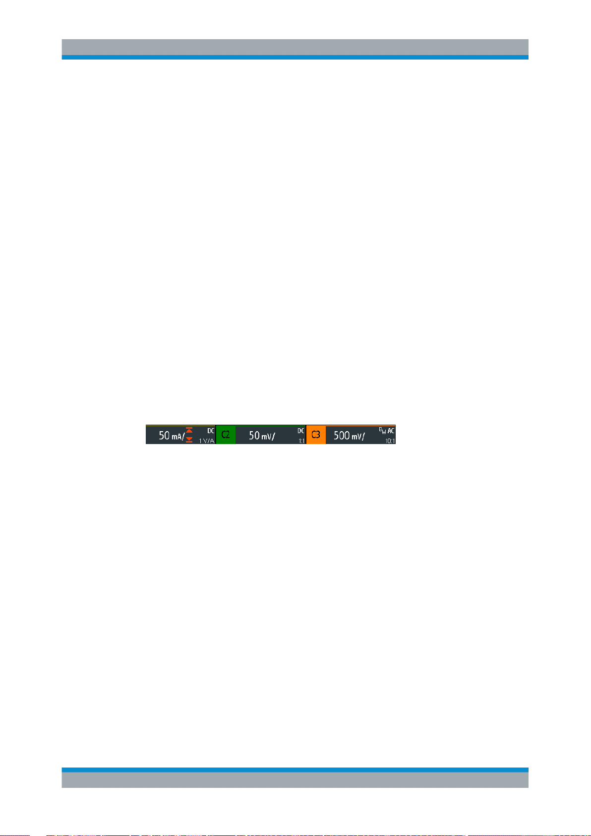
R&S®RTB2000
Waveform Setup
Vertical Setup
PRESET
Resets the instrument to the default state, without analyzing the signal. The previous
user-defined configuration is removed and all channels except for channel 1 are disabled.
Remote command:
*RST
AUTOSET
Analyzes the enabled analog channel signals, and adjusts the horizontal, vertical, and
trigger settings to display stable waveforms.
Remote command:
AUToscale on page 250
4.2 Vertical Setup
The controls and parameters of the vertical system adjust the vertical scale and position of the waveform, and the waveform display. The probe settings also belong to the
vertical setup.
The channel labels at the bottom of the display show the basic vertical settings: vertical
scale (for example, channel 3 in the figure below: 500 mV/div), coupling (AC), probe
attenuation (10:1), and bandwidth (if limited). Clipping of a waveform is indicated by
orange arrows. The label of the selected channel has a brighter colored line on the top.
Figure 4-1: Channel labels. Channel 3 is selected. Channel 1 waveform is clipped.
There are several ways to adjust vertical settings:
●
Use the controls in the Vertical functional block of the front panel to select the
channel, to scale the waveform, and to set the offset.
●
Drag one finger vertically on the screen to change the offset of the selected channel waveform.
●
spread or pinch two fingers in vertical direction to change the vertical scale of the
selected waveform.
●
Use the short menu to adjust coupling and the probe.
●
Use the comprehensive menu to adjust all vertical settings.
37User Manual 1333.1611.02 ─ 03
Page 46

R&S®RTB2000
Waveform Setup
Vertical Setup
4.2.1 VERTICAL Controls
CH <N>
For each analog channel, a channel key is available. The key is illuminated in the
channel color, if the channel is on.
The effect of the keypress depends on state of the channel:
●
If channel is off: Turns on the channel and selects it. The rotary knobs alongside
light up in the channel color.
●
If the channel is on and in focus (selected): Opens its vertical setup menu of the
channel.
●
If the channel is on but not in focus (not selected): Selects the channel waveform.
●
If the channel is selected and the menu is open: Pressing the key turns off the
channel.
Remote command:
CHANnel<m>:STATe on page 252
OFFSET / POSITION (UPPER KNOB)
The rotary knob adjusts the offset of an analog channel, or the vertical position of a
math or reference waveform, serial bus, or logic pod.
The knob lights up in the color of the selected waveform. Turn clockwise to move up
the waveform. Pressing the key sets the value to zero.
Remote command:
CHANnel<m>:OFFSet on page 254
CALCulate:QMATh:POSition on page 278
REFCurve<m>:VERTical:POSition on page 281
SCALE
Sets the vertical scale in Volts per division to change the displayed amplitude of the
selected waveform. For analog waveforms, the scale value is shown in the waveform
label at the bottom. The knob lights up in the color of the selected waveform.
Turn SCALE clockwise to stretch the waveform. Doing so, the scale value V/div
decreases. Press the knob to toggle between fine and coarse adjustment.
38User Manual 1333.1611.02 ─ 03
Page 47
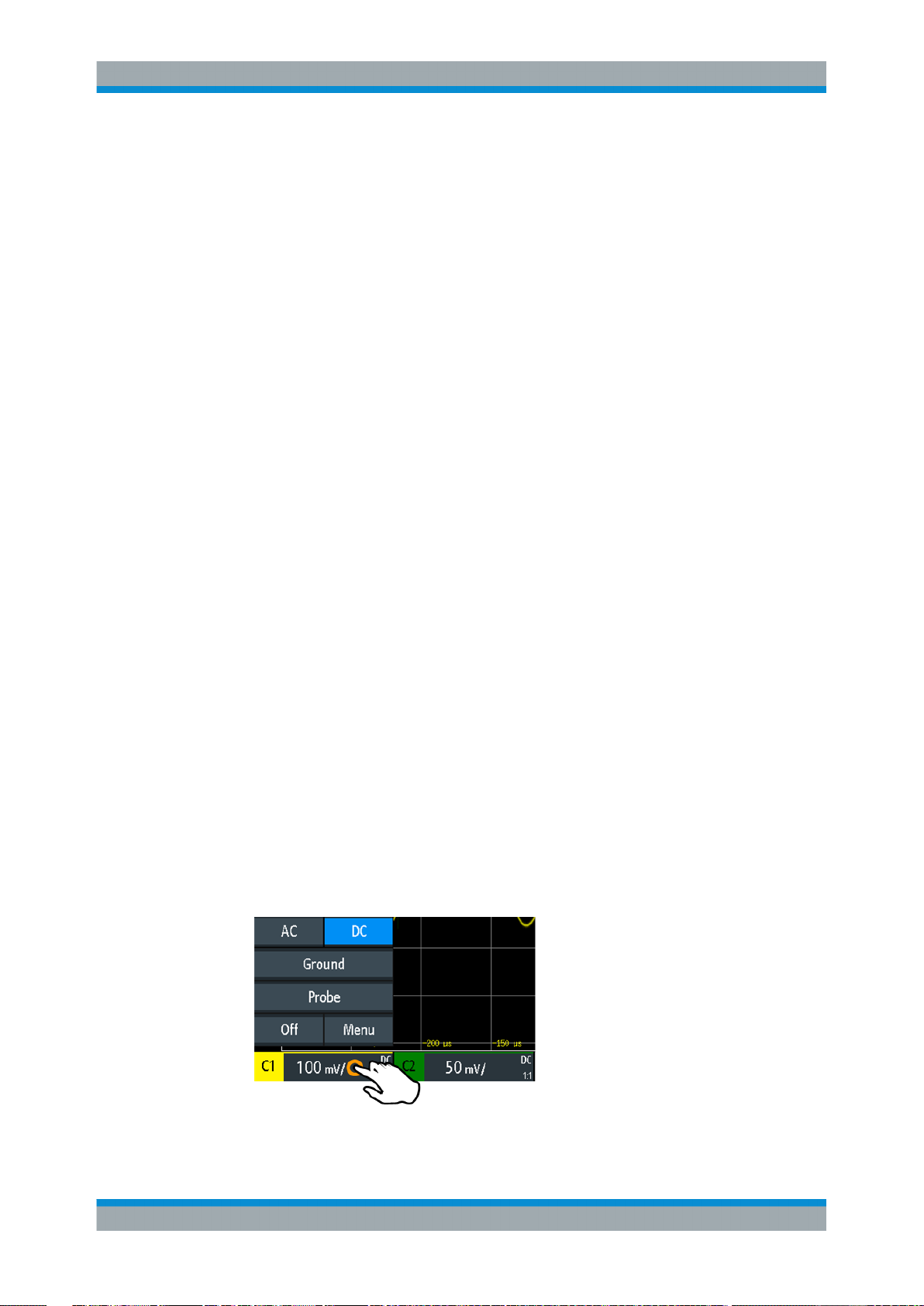
R&S®RTB2000
Waveform Setup
Vertical Setup
To get the maximum resolution of the waveform amplitude, make sure that the waveforms cover most of the screen's height.
Remote command:
CHANnel<m>:SCALe on page 253
CALCulate:QMATh:SCALe on page 278
REFCurve<m>:VERTical:SCALe on page 281
LOGIC
Enables the logic channels. The second keypress opens the menu, where you can
select and configure digital channels for analysis. If the menu is open, pressing the key
disables the logic channels.
Key function requires MSO option R&S RTB-B1.
Logic analyzer functions are described in Chapter 13, "Logic Analyzer (Option
R&S RTB-B1, MSO)", on page 220.
REF
Displays the reference waveforms with their last configuration. The key works in the
same way as the channel keys, see "CH <N>" on page 38.
Reference wavforms are described in Chapter 6.3, "Reference Waveforms",
on page 74.
MATH
Enables the math waveform, a waveform calculated from the captured data. The key
works in the same way as the channel keys, see "CH <N>" on page 38.
Mathematics is described in Chapter 6.2, "Mathematics", on page 71.
4.2.2 Short Menu for Analog Channels
To adjust the probe and the coupling, you can use the short menu. Here you can also
open the comprehensive menu, and switch off the channel.
► To open the short menu for a channel, tap the channel label in the bottom line of
the display.
If the channel was not selected, tap twice: Once to select the waveform, and next
to open the short menu.
39User Manual 1333.1611.02 ─ 03
Page 48

R&S®RTB2000
Functions in the short menu:
●
"AC | DC": see "Coupling" on page 40
●
"Ground" on page 41
●
"Probe": opens the "Probe" menu, see
●
"Off": turns off the channel.
●
"Menu": opens the comprehensive "Vertical" menu.
Waveform Setup
Vertical Setup
4.2.3 Vertical Settings
The comprehensive "Vertical" menu contains all vertical settings.
► To open the menu for a channel, press the corresponding channel key.
If the channel was active but not selected, press twice: Once to select the waveform, and next to open the short menu.
The "Vertical" menu is also available in the main menu.
Figure 4-2: Vertical setup dialog, here split into two halves
State
Switches the selected channel on or off.
Remote command:
CHANnel<m>:STATe on page 252
Coupling
Selects the input coupling, which influences the signal path between input connector
and the following internal signal stage. The current coupling of each channel is shown
in the waveform labels below the grid.
40User Manual 1333.1611.02 ─ 03
Page 49

R&S®RTB2000
Waveform Setup
Vertical Setup
"AC"
"DC"
Remote command:
CHANnel<m>:COUPling on page 254
Ground
Connects the input to a virtual ground. All channel data is set to 0 V. Ground connection is labeled with
Remote command:
CHANnel<m>:COUPling on page 254
Bandwidth
Selects the bandwidth limit. The specified full bandwidth indicates the range of frequencies that the instrument can acquire and display accurately with less than 3 dB
attenuation.
For analog applications, the highest signal frequency determines the required oscilloscope bandwidth. The oscilloscope bandwidth should be at least 3 times higher than
the maximum frequency included in the analog test signal to measure the amplitude
without aliasing.
Most test signals are more complex than a simple sine wave and include several spectral components. A digital signal, for example, is built up of several odd harmonics. For
digital signals, the oscilloscope bandwidth should be at least 5 times higher than the
clock frequency to be measured.
The oscilloscope is not an autonomous system. You need a probe to measure the signal, and the probe has a limited bandwidth, too. The combination of oscilloscope and
probe creates a system bandwidth. To reduce the effect of the probe on the system
bandwidth, the probe bandwidth should exceed the bandwidth of the oscilloscope, the
recommended factor is 1.5 x oscilloscope bandwidth.
"20 MHz"
AC coupling is useful if the DC component of a signal is of no interest. AC coupling blocks the DC component of the signal so that the
waveform is centered on zero volts.
With DC coupling, the input signal passes unchanged, all signal components are shown.
. The coupling is not affected by the ground setting.
Frequency limit. Higher frequencies are removed to reduce noise.
Limited bandwidth is indicated by "BW" in the waveform label.
"Full"
Remote command:
CHANnel<m>:BANDwidth on page 254
Invert
Turns the inversion of the signal amplitude on or off. To invert means to reflect the voltage values of all signal components against the ground level. Inversion affects only the
display of the signal but not the trigger.
For example: if the oscilloscope triggers on the rising edge, the trigger is not changed
by inversion, but the actually rising edge is displayed as falling edge.
Inversion is indicated in the waveform labels by line above the channel name.
At full bandwidth, all frequencies in the specified range are acquired
and displayed. Full bandwidth is used for most applications.
41User Manual 1333.1611.02 ─ 03
Page 50

R&S®RTB2000
Waveform Setup
Vertical Setup
Remote command:
CHANnel<m>:POLarity on page 255
Vertical Scale
Sets the vertical scale in Volts per division to change the displayed amplitude of the
selected waveform. The current value is shown in the waveform label below the grid.
Vertical scale directly affects the resolution of the waveform amplitude. To get the full
resolution of the ADC, set up the waveforms to cover most of the height of the diagram.
Remote command:
CHANnel<m>:SCALe on page 253
Offset
The offset voltage is used to correct an offset-affected signal. The vertical center of the
selected channel is shifted by the offset value and the signal is repositioned within the
diagram area. To set the offset automatically, use Autoset.
Use the offset to measure small AC voltages that are overlaid by higher DC voltages.
Unlike AC coupling, the DC part of the signal is not lost with offset setting.
Remote command:
CHANnel<m>:OFFSet on page 254
Deskew
Sets a time delay for the selected channel.
Deskew compensates delay differences between channels caused by the different
length of cables, probes, and other sources. Correct deskew values are important for
accurate triggering. Signals that are routed over lines with different lengths have a different propagation delay. This delay may lead to a non-synchronous waveform display.
For example, a coax cable with a length of 1 meter has a propagation delay of typically
5.3 ns.
Remote command:
CHANnel<m>:SKEW on page 255
Zero Offset
Differences in DUT and oscilloscope ground levels can cause larger zero errors, which
affect the waveform. If the DUT is ground-referenced, the "Zero Offset" corrects the
zero error and sets the probe to the zero level.
You can assess the zero error by measuring the mean value of a signal that returns
zero.
Remote command:
CHANnel<m>:ZOFFset[:VALue] on page 255
Waveform Color
Selects the color scale for the display of the waveform. Each scale comprises a set of
colors, where each color represents a certain frequency of occurrence.
"Temperature"
Display in temperature colors. Blue corresponds to rare occurrences
of the samples, while white indicates frequent ones.
42User Manual 1333.1611.02 ─ 03
Page 51

R&S®RTB2000
Waveform Setup
Vertical Setup
"Rainbow"
Display in rainbow colors. Blue corresponds to rare occurrences of
the samples, while red indicates frequent ones.
"Fire"
Display in fire colors. Yellow corresponds to rare occurrences of the
samples, while red indicates frequent ones.
"Default"
4.2.4 Probe Settings
Displays the waveform in its default monochrome color.
In the probe menu, you set the probe attenuation for the selected channel. You can
select a default factor, for example "10:1", or enter a user-defined value.
Access: CH <N> > "Probe" (scroll down). Or: short menu > "Probe"
User
If default values do not fit, you can enter an arbitrary attenuation factor in the range
between 0.001:1 and 1000:1. The vertical scaling and measured values are multiplied
by this factor so that the displayed values are equal to the undivided measured signal
values.
Remote command:
PROBe<m>:SETup:ATTenuation:MANual on page 258
Unit
Selects the unit that the probe can measure.
●
V - for voltage measurements
●
A - for current measurements
Remote command:
PROBe<m>:SETup:ATTenuation:UNIT on page 258
Probe Adjust
Starts the probe adjustment procedure. A wizard explains the adjustment step by step.
43User Manual 1333.1611.02 ─ 03
Page 52

R&S®RTB2000
Waveform Setup
Vertical Setup
4.2.5 Threshold Settings
A threshold is used for digitization of analog signals. If the signal value is higher than
the threshold, the signal state is high (1 or true for the Boolean logic). Otherwise, the
signal state is considered low (0 or false) if the signal value is below the threshold.
Access: CH <N> > "Threshold" (scroll down).
Threshold
A threshold is used for digitization of analog signals. If the signal value is higher than
the threshold, the signal state is high (1 or true for the Boolean logic). Otherwise, the
signal state is considered low (0 or false) if the signal value is below the threshold.
Remote command:
CHANnel<m>:THReshold on page 256
Hysteresis
To avoid the change of signal states due to noise, set the hysteresis. If the signal jitters
inside the hysteresis range and crosses the threshold, no state transition occurs.
Threshold
Logic 0 Logic 1 Logic 0
Hysteresis
The numerical values of "Small", "Medium", and "Large" hysteresis correspond to the
vertical scale.
Remote command:
CHANnel<m>:THReshold:HYSTeresis on page 257
Find Threshold
The instrument analyzes the channel and sets the threshold for digitization. If no level
can be found, the existing value remains unchanged, and you can set the thresholds
manually.
Remote command:
CHANnel<m>:THReshold:FINDlevel on page 256
44User Manual 1333.1611.02 ─ 03
Page 53

R&S®RTB2000
Waveform Setup
Horizontal Setup
4.2.6 Label Settings
In the "Label" menu, you can define a name label for the selected waveform.
Access: CH <N> > "Label" (scroll down).
Label
Activates or deactivates the label display. The label is shown at the waveform on the
right edge of the display.
Remote command:
CHANnel<m>:LABel:STATe on page 257
Predefined Label
Selects a predefined label text. You can edit the text with "Edit Label".
Edit Label
Opens on-screen keypad to enter a label text. If you previously have selected a text
from the library, it is already written in the entry line, and you can modify it.
The maximum name length is 8 characters, and only ASCII characters provided on the
on-screen keypad can be used.
Remote command:
CHANnel<m>:LABel on page 257
4.3 Horizontal Setup
Horizontal settings, also known as timebase settings, adjust the waveforms in horizontal direction.
Typically, the trigger is the determining point of the waveform record. In many scenarios, you want to analyze the waveform some time before or after the trigger. To adjust
the horizontal acquisition window to the waveform section of interest, you can use the
following parameters:
●
The horizontal position defines the time distance of the trigger point (the zero
point of the diagram) to the reference point. Changing the horizontal position, you
can move the trigger point, even outside the screen.
●
The reference point is the rescaling center of the time scale on the screen. If you
modify the time scale, the reference point remains fixed on the screen, and the
scale is stretched or compressed to both sides of the reference point.
45User Manual 1333.1611.02 ─ 03
Page 54

R&S®RTB2000
Waveform Setup
Horizontal Setup
Unlike vertical settings, which are waveform-specific, the horizontal settings apply to all
active waveforms.
There are several ways to adjust horizontal settings:
●
Use the controls in the Horizontal functional block of the front panel to scale the
waveforms, and to set the position.
●
Drag one finger horizontally on the screen to change the horizontal position.
Spread or pinch two fingers to change the horizontal scale.
●
Use shortcuts to adjust scale and position.
●
Use the comprehensive menu to adjust all horizontal settings.
4.3.1 HORIZONTAL Controls
POSITION
Changes the trigger position, the time distance from the trigger point to the reference
point (trigger offset). The trigger point is the zero point of the diagram. Thus, you can
set the trigger point even outside the diagram and analyze the signal some time before
or after the trigger.
46User Manual 1333.1611.02 ─ 03
Page 55

R&S®RTB2000
Waveform Setup
Horizontal Setup
Turn clockwise to move the position to the right, and press the knob to reset the value
to zero. The current value is shown in the information bar.
In zoom and FFT, the knob sets the position in the active diagram. Tap the diagram
that you want to adjust. If a zoom is active, either the position of the zoom window or
the trigger position is changed. In an FFT diagram, the knob changes the center frequency in frequency domain, or the trigger position in time domain.
Remote command:
TIMebase:POSition on page 259
REFCurve<m>:HORizontal:POSition on page 281
TIMebase:ZOOM:TIME on page 276
SCALE
Adjusts the time scale of the horizontal axis for all signals, also known as timebase.
Turn clockwise to stretch the waveforms - the scale value time/div decreases. Press
the knob to toggle between coarse and fine scale adjustment. The current value is
shown in the information bar.
In a zoom diagram, the knob changes the zoom scale. In an FFT diagram, the knob
changes the span. Tap the diagram that you want to adjust.
Remote command:
TIMebase:SCALe on page 258
REFCurve<m>:HORizontal:SCALe on page 281
TIMebase:ZOOM:SCALe on page 276
ZOOM
Enables or disables the zoom with the last configuration.
See also: Chapter 6.1, "Zoom", on page 69.
Remote command:
TIMebase:ZOOM:STATe on page 276
HORIZONTAL
Opens the menu to configure horizontal scale, position, and reference point. The current scale and position is shown in the top information bar.
If zoom is active, you can find also the zoom scale and zoom position in this menu.
ACQUISITION
Opens the "Acquisition" menu. Here you control the data processing - how the waveform is built from the captured samples. The current acquisition mode is shown in the
top information bar.
See also: Chapter 4.4, "Acquisition Setup", on page 49.
4.3.2 Shortcuts for Horizontal Settings
To adjust the horizontal scale and the position, you can use the shortcuts on the top of
the display. The labels show the current values.
47User Manual 1333.1611.02 ─ 03
Page 56

R&S®RTB2000
Waveform Setup
Horizontal Setup
1 = adjust horizontal scale
2 = adjust horizontal position
4.3.3 Horizontal Settings
The comprehensive "Horizontal" menu contains all horizontal settings. In zoom mode,
also zoom settings are listed in the menu.
► To open the menu, press the HORIZONTAL key.
Reference Point
Defines the time reference point in the diagram. It is indicated by a gray triangle outline
at the bottom of the diagram.
The reference point defines which part of the waveform is shown. By default, the reference point is displayed in the center of the window, and you can move it to the left or
right.
The reference point is the rescaling center of the time scale on the screen. If you modify the time scale using the SCALE knob, the reference point remains fixed on the
screen, and the scale is stretched or compressed to both sides of the reference point.
If you spread and pinch two fingers on the touchscreen to change the time scale, then
the reference point is set between the fingers.
Remote command:
TIMebase:REFerence on page 259
Time Scale
Defines the time scale of the horizontal axis for all signals, also known as timebase.
The scaling is indicated in the information bar above the grid.
Remote command:
TIMebase:SCALe on page 258
48User Manual 1333.1611.02 ─ 03
Page 57

R&S®RTB2000
Waveform Setup
Acquisition Setup
Horizontal Position
Defines the trigger position, the time distance from the trigger point to the reference
point (trigger offset). The trigger point is the zero point of the diagram. Changing the
horizontal position, you can move the trigger, even outside the screen.
If you want to see a section of the waveform some time before or after the trigger,
enter this time as horizontal position. The requested waveform section is shown
around the reference point. Use positive values to see waveform sections after the trigger - the waveform and the diagram origin move to the left.
The value is indicated in the information bar above the grid.
Remote command:
TIMebase:POSition on page 259
4.4 Acquisition Setup
During an acquisition, the R&S RTB2000 captures the signal and converts it to digital
samples. The digital samples are processed according to the acquisition settings. The
result is a waveform record that is displayed on the screen and stored in memory.
The number of waveform samples in one waveform record is called the record length.
The rate of recording waveform samples - the number of waveform samples per second - is the sample rate. The higher the sample rate, the better is the resolution and
the more details of the waveform are visible.
A sufficient resolution is essential for correct reconstruction of the waveform. If the signal is undersampled, aliasing occurs - a false waveform is displayed. To avoid aliasing
and accurately reconstruct a signal, the sample rate must be at least 3 to 5 times the
fastest frequency component of the signal.
There are several ways to adjust and control acquisition:
●
Use the controls in the Trigger functional block of the front panel to start and stop
acquisition. See Chapter 5.1, "Trigger Controls", on page 53.
●
Use shortcuts to adjust the acquisition mode, and to perform a single acquisition.
●
Use the comprehensive menu to adjust all acquisition settings.
► To start or stop acquisition, use the RUN STOP and SINGLE keys in the Trigger
section at the front panel.
4.4.1 Shortcuts for Acquisition Settings
To adjust the acquisition mode, and to perform a single acquisition, you can use the
shortcuts on the top of the display. The labels show the current values.
49User Manual 1333.1611.02 ─ 03
Page 58

R&S®RTB2000
Waveform Setup
Acquisition Setup
1 = start or stop a continuous acquisition, or start a single acquisition if SINGLE is active
2 = adjust the acquisition mode
3 = shows the current sample rate for information
4.4.2 Acquisition Settings
Acquisition settings define the processing of the captured samples in the instrument.
The current acquisition mode and sample rate are shown in the top information bar.
► To adjust acquisition settings, press the ACQUISITION key.
Record Length
The instrument acquires the signals with an either automatically or selected record
length. Record length is the number of waveform samples that are stored in one waveform record.
With automatic record length, the instrument combines sample rate and record length
to acquire at maximum sample rate. In connection with persistence, this mode can display rare signal anomalies.
Each predefined record length corresponds to a maximum number of history segments, which are stored in the instrument's memory. If option R&S RTB-K15 is installed, you can display the history segments.
Remote command:
ACQuire:POINts:AUTomatic on page 260
ACQuire:POINts[:VALue] on page 261
50User Manual 1333.1611.02 ─ 03
Page 59

R&S®RTB2000
Waveform Setup
Acquisition Setup
Acquire Mode
Defines how the waveform is built from the captured samples. There are two general
methods to build the waveform record: sample decimation and waveform arithmetic.
Sample decimation reduces the data stream of the ADC to a stream of waveform
points with lower sample rate and a less precise time resolution. The R&S RTB2000
uses decimation, if the waveform sample rate is less than the ADC sample rate. The
acquisition modes "Peak Detect" and "High Resolution" are decimation methods.
Waveform arithmetic builds the resulting waveform from several consecutive acquisitions of the signal. The acquisition modes "Average" and "Envelope" are arithmetic
methods.
"Sample"
"Peak Detect"
"High Resolution"
"Average"
"Envelope"
"Envelope + PD"
Remote command:
ACQuire:TYPE on page 262
CHANnel<m>:ARIThmetics on page 262
CHANnel<m>:TYPE on page 261
ACQuire:PEAKdetect on page 263
ACQuire:HRESolution on page 263
Usually, most signals are displayed optimally with this acquisition
mode but very short glitches might remain undiscovered by this
method. If the sample rate of the waveform is less than the ADC sample rate, the instrument reduces the number of samples: one of n
samples in a sample interval is recorded as waveform point, the other
samples are discarded (decimation). Conversely, if the sample rate of
the waveform is higher than the ADC sample rate, the instrument
adds waveform points to the captured samples using an interpolation
method.
The minimum and the maximum of n samples are recorded as waveform points, the other samples are discarded. Thus the instrument
can detect fast signal peaks at slow time scale settings that would be
missed with other acquisition modes.
The average of n captured sample points is recorded as one waveform sample. Averaging reduces the noise, the result is a more precise waveform with higher vertical resolution.
The average is calculated from the data of the current acquisition and
a number of consecutive acquisitions before. The method reduces
random noise. It requires a stable, triggered and repetitive signal.
The number of acquisitions for average calculation is defined with
"No. of Averages" on page 52.
Each acquisition is done in sample decimation mode, and the minimum and maximum values over some consecutive acquisitions build
the envelope. The resulting diagram shows two envelope waveforms
below and above the normal waveform: the minimums (floor) and
maximums (roof), representing the borders in which the signal
occurs. this method is useful, for example, if the waveform is noisy
but the noise is not relevant for the measurement.
Each acquisition is done in peak detect decimation mode, and the
most extreme values of all consecutive acquisitions build the envelope. This method is more precise than "Envelope".
51User Manual 1333.1611.02 ─ 03
Page 60

R&S®RTB2000
Waveform Setup
Acquisition Setup
No. of Averages
Defines the number of waveforms used to calculate the average waveform, if "Acquire
Mode" = "Average". The higher the number, the better the noise is reduced.
To restart the average calculation, press the CLEAR SCREEN key.
Remote command:
ACQuire:AVERage:COUNt on page 263
ACQuire:AVERage:RESet on page 264
Nx Single
Sets the number of waveforms that are acquired with a SINGLE acquisition.
Remote command:
ACQuire:NSINgle:COUNt on page 251
Roll
Enables the roll mode.
The roll mode displays the untriggered, continuous signal. The roll mode moves the
captured input data on the display from the right to the left. The instrument shows the
waveform immediately, without waiting for the complete acquisition of the waveform
record.
Remote command:
TIMebase:ROLL:ENABle on page 264
Interpolation
Selects the interpolation method if interpolation is required to get the defined record
length.
"Sin(x)/x"
"Linear"
"Sample-Hold"
Remote command:
ACQuire:INTerpolate on page 264
Two adjacent ADC sample points are connected by a sin(x)/x curve,
and also the adjoining sample points are considered by this curve.
The interpolated points are placed on the resulting curve. This interpolation method is the default method. It is precise and shows the
best signal curve.
Two adjacent ADC sample points are connected by a straight line,
the interpolated points are placed on the line. You see a polygonal
waveform similar to the real signal, and also the ADC sample points
as vertexes.
The ADC sample points are displayed like a histogram. For each
sample interval, the voltage is taken from the sample point and considered as constant, and the intervals are connected with vertical
lines. Thus, you see the discrete values of the ADC.
52User Manual 1333.1611.02 ─ 03
Page 61

R&S®RTB2000
5 Trigger
Trigger
Trigger Controls
Triggering means to capture the interesting part of the relevant waveforms. Choosing
the right trigger type and configuring all trigger settings correctly allows you to detect
various incidents in signals.
A trigger occurs if the trigger conditions are fulfilled. The instrument acquires continuously and keeps the sample points to fill the pretrigger part of the waveform record.
When the trigger occurs, the instrument continues acquisition until the posttrigger part
of the waveform record is filled. Then it stops acquiring and displays the waveform.
When a trigger is recognized, the instrument does not accept another trigger until the
acquisition is complete.
Trigger conditions include:
●
Source of the trigger signal (channel)
●
Trigger type and its setup
●
Trigger mode
In addition, the horizontal position of the trigger point and the reference point are
important to display the interesting part of the signal. See Chapter 4.3, "Horizontal
Setup", on page 45.
The trigger level and position are marked in the grid. The markers have the color of the
trigger source. Information on the most important trigger settings is shown in the upper
information bar.
There are several ways to set up the trigger:
●
Use the controls in the Trigger functional block of the front panel.
●
Use shortcuts to adjust the trigger source, trigger mode, and main parameters of
the trigger type.
●
Use the comprehensive menu to select the trigger type and to adjust all trigger settings.
● Trigger Controls...................................................................................................... 53
● Shortcuts for Trigger Settings................................................................................. 55
● General Trigger Settings.........................................................................................56
● Edge Trigger........................................................................................................... 58
● Width Trigger...........................................................................................................59
● Video Trigger...........................................................................................................62
● Pattern Trigger........................................................................................................ 64
● Timeout Trigger.......................................................................................................66
5.1 Trigger Controls
The keys and the rotary knob in the Trigger functional block adjust the trigger and start
or stop acquisition.
The green LED above the LEVELS knob lights up when the instrument triggers.
53User Manual 1333.1611.02 ─ 03
Page 62

R&S®RTB2000
Trigger
Trigger Controls
TRIGGER
Opens the "Trigger" menu.
SOURCE
Changes the analog trigger source. Press the key repeatedly until the required analog
source is selected. If a digital source or serial bus was selected in the "Trigger" menu,
or if the "Trigger Type" is set to "Pattern", the key opens the menu.
The key lights up in the color of the selected channel, and the selected source is
shown in the information bar.
Remote command:
TRIGger:A:SOURce on page 266
AUTO NORM
Toggles the trigger mode between "Auto" and "Norm". The key lights up in white if the
trigger mode is "Norm". The current mode is also shown in the information bar.
"Auto"
"Norm"
Remote command:
TRIGger:A:MODE on page 266
LEVELS
The rotary knob changes the trigger level. Turn clockwise to move up the trigger level.
Pressing the knob sets the level to 50% of the signal amplitude.
Remote command:
TRIGger:A:LEVel<n>[:VALue] on page 268
TRIGger:A:FINDlevel on page 268
The instrument triggers repeatedly after a time interval if the trigger
conditions are not fulfilled. If a real trigger occurs, it takes precedence. This mode helps to see the waveform even before the trigger
is set. The waveform on the screen is not synchronized, and successive waveforms are not triggered at the same point of the waveform.
The instrument acquires a waveform only if a trigger occurs, that is, if
all trigger conditions are fulfilled. If no trigger occurs, no waveform is
acquired and the last acquired waveform is displayed. If no waveform
was captured before, nothing is displayed.
FORCE TRIGGER
Provokes an immediate single acquisition. Use this key if the acquisition is running in
normal mode and no valid trigger occurs. Thus you can confirm that a signal is available and use the waveform display to determine how to trigger on it.
54User Manual 1333.1611.02 ─ 03
Page 63

R&S®RTB2000
Trigger
Shortcuts for Trigger Settings
RUN STOP
Starts and stops the continuous acquisition. A green light indicates a running acquisition. A red light shows that acquisition is stopped. At slow timebases, a yellow light
indicates that the acquisition is ongoing.
The status is shown also at the right end of the information bar: "Run", "Complete",
"Trig?" (waiting for trigger, in normal trigger mode) or "Not ready" (working). For slow
timebases, the status "Pre" or "Post" is shown together with an indicator that shows the
filling level of the buffer.
Remote command:
RUN on page 251
RUNContinous on page 251
STOP on page 251
ACQuire:STATe on page 251
SINGLE
Starts a specified number of acquisitions. A white light indicates that the instrument is
in single mode. The information bar shows "Complete" if the acquisition has been finished.
To set the number of acquisitions, press the ACQUISITION key and enter "Nx Single".
Remote command:
SINGle on page 251
RUNSingle on page 251
5.2 Shortcuts for Trigger Settings
To adjust the trigger source, mode, and trigger type specific settings, you can use the
shortcuts on the top of the display. The labels show the current values.
= adjust the trigger source
1
2 = open the keypad to enter the value of the trigger level or threshold
3 = adjust slope or polarity
4 = adjust the trigger mode
5 = start or stop a continuous acquisition, or start a single acquisition if SINGLE is active
6 = available settings depend on the trigger type
55User Manual 1333.1611.02 ─ 03
Page 64

R&S®RTB2000
Trigger
General Trigger Settings
5.3 General Trigger Settings
General trigger settings are independent of the trigger type. They are highlighted in the
above figure and described in the current section. The other trigger settings are specific for individual trigger types, and they are described in the following sections.
Trigger Mode
Toggles the trigger mode between "Auto" and "Auto". The trigger mode determines the
behavior of the instrument if no trigger occurs. The current setting is shown in the information bar.
"Auto"
The instrument triggers repeatedly after a time interval if the trigger
conditions are not fulfilled. If a real trigger occurs, it takes precedence. This mode helps to see the waveform even before the trigger
is set. The waveform on the screen is not synchronized, and successive waveforms are not triggered at the same point of the waveform.
"Norm"
The instrument acquires a normal waveform only, if a trigger occurs,
that is, if all trigger conditions are fulfilled. If no trigger occurs, no
waveform is acquired and the last acquired waveform is displayed. If
no waveform was captured before, nothing is displayed.
Remote command:
TRIGger:A:MODE on page 266
Trigger Type
Selects the trigger type.
56User Manual 1333.1611.02 ─ 03
Page 65

R&S®RTB2000
Trigger
General Trigger Settings
"Edge"
"Width"
"Video"
"Pattern"
"Timeout"
"Line"
"Serial Bus"
Remote command:
TRIGger:A:TYPE on page 267
Triggers on signal edges.
See Chapter 5.4, "Edge Trigger", on page 58.
Triggers on pulse width.
See Chapter 5.5, "Width Trigger", on page 59.
Triggers on various PAL, NTSC and HDTV standard video signals.
See Chapter 5.6, "Video Trigger", on page 62.
Triggers on logical combinations of the input channels.
See Chapter 5.7, "Pattern Trigger", on page 64.
Triggers on signal level timeout.
See Chapter 5.8, "Timeout Trigger", on page 66.
The line trigger uses the waveform of the power supply's alternating
line voltage (typically 50 Hz or 60 Hz AC) as the trigger signal source.
Use this trigger to detect issues related to the frequency of the power
grid.
The line trigger does not have any settings.
Triggers on a serial bus. Requires that at least one protocol option
R&S RTB-K1, -K2, or -K3 is installed, a serial bus is configured, and
a decoded signal is available.
See Chapter 12.1.1, "Protocol - Common Settings", on page 165.
Source
Selects the trigger source.
"C1, C2, C3,
C4"
"D0 to D15"
"Extern"
"B1, B2"
Remote command:
TRIGger:A:SOURce on page 266
Hold Off, Hold Off Time
Enables the hold off and defines the "Hold Off Time". The next trigger occurs only after
the hold off time has passed.
The trigger hold off defines when the next trigger event is recognized after the current
trigger event. Thus, it affects the next trigger to occur after the current one. Hold off
helps to obtain stable triggering when the oscilloscope is triggering on undesired
events.
Remote command:
TRIGger:A:HOLDoff:MODE on page 267
TRIGger:A:HOLDoff:TIME on page 268
Select one of the analog input channels as trigger source.
Select one of the digital channels as trigger source if MSO option
R&S RTB-B1 is installed.
Sets the external trigger input on the front panel as trigger source.
Serial buses 1 or 2, used for triggering on protocols. Only available, if
the trigger type "Serial Bus" is selected.
57User Manual 1333.1611.02 ─ 03
Page 66

R&S®RTB2000
Trigger
Edge Trigger
5.4 Edge Trigger
The edge trigger is the most common trigger type. The trigger occurs when the signal
from the trigger source passes the trigger level in the specified direction (slope).
Figure 5-1: Edge trigger event with positive slope (rising edge)
► TRIGGER > "Trigger Type" = "Edge"
Slope.............................................................................................................................58
Trigger Level, Threshold............................................................................................... 58
Coupling........................................................................................................................59
HF Reject...................................................................................................................... 59
Noise Reject..................................................................................................................59
Slope
Sets the edge direction for the trigger. You can trigger on:
●
●
●
rising edge, that is a positive voltage change
falling edge, that is a negative voltage change
rising and falling edge. After starting an acquisition, the instrument triggers on
the first identified edge.
Remote command:
TRIGger:A:EDGE:SLOPe on page 268
Trigger Level, Threshold
Sets the voltage level or threshold for the trigger.
58User Manual 1333.1611.02 ─ 03
Page 67

R&S®RTB2000
Trigger
Width Trigger
You can also drag the trigger level marker on the display, or turn the Levels knob. To
set the trigger level to 50% of the signal amplitude, press the Levels knob.
For width and timeout trigger, the trigger level is the threshold of the trigger source.
Remote command:
TRIGger:A:LEVel<n>[:VALue] on page 268
TRIGger:A:FINDlevel on page 268
Coupling
Sets the coupling for the trigger source.
"AC"
Alternating current coupling. A highpass filter removes the DC offset
voltage from the trigger signal.
"DC"
"LF Reject"
Direct current coupling. The trigger signal remains unchanged.
Sets the trigger coupling to high frequency. A 15 kHz highpass filter
removes lower frequencies from the trigger signal. Use this mode
only with very high frequency signals.
Remote command:
TRIGger:A:EDGE:COUPling on page 269
HF Reject
Enables or disables an additional 5 kHz lowpass filter in the trigger path. This filter
removes higher frequencies and is available with AC and DC coupling.
You can use either "HF Reject" or "Noise Reject".
Remote command:
TRIGger:A:EDGE:FILTer:HFReject on page 269
Noise Reject
Extends the hysteresis to avoid unwanted trigger events caused by noise oscillation
around the trigger level.
You can use either "HF Reject" or "Noise Reject".
Remote command:
TRIGger:A:EDGE:FILTer:NREJect on page 269
5.5 Width Trigger
The width trigger compares the pulse width (duration) with given time limits. It detects
pulses with an exact pulse width, pulses shorter or longer than a given time, and also
pulses inside or outside the allowable time range. The pulse width is measured at the
trigger level.
You can use the width trigger, for example, to trigger on glitches.
59User Manual 1333.1611.02 ─ 03
Page 68

R&S®RTB2000
Trigger
Width Trigger
Figure 5-2: Pulse width is shorter (left) or longer (right) than a given duration (also known as glitch
Figure 5-3: Pulse width is inside or outside an allowable time range
1 = Inside: min width < pulse < max width
2 = Outside: pulse < min width OR pulse > max width
min
max
±Δ
trigger)
min
1 2
max
±Δ
1 2
Figure 5-4: Pulse width is equal or unequal to a given duration, with optional variation (Δ)
1 = Equal: (width - variation) < pulse < (width + variation)
2 = Unequal: pulse < (width - variation) OR pulse > (width + variation)
► TRIGGER > "Trigger Type" = "Width"
60User Manual 1333.1611.02 ─ 03
Page 69

R&S®RTB2000
Trigger
Width Trigger
Polarity.......................................................................................................................... 61
Comparison...................................................................................................................61
Time t............................................................................................................................ 62
Variation........................................................................................................................62
Time t1, Time t2............................................................................................................ 62
Threshold...................................................................................................................... 62
Hysteresis..................................................................................................................... 62
Polarity
Sets the polarity of the pulse. You can trigger on:
●
●
Remote command:
TRIGger:A:WIDTh:POLarity on page 270
Comparison
Sets how the measured pulse width is compared with the given limits.
"Width >"
"Width <"
"Width ="
positive going pulse, the width is defined from the rising to the falling slopes.
negative going pulse, the width is defined from the falling to the rising slopes.
Triggers on pulse width longer than the reference "Time t".
Triggers on pulse width shorter than the reference "Time t".
Triggers on pulse width equal to the reference "Time t" if "Variation"
Δt = 0.
If "Variation" ≠ 0, this setting triggers on pulses within the range t±Δt.
"Width ≠"
Triggers on pulses unequal to the reference "Time t", if "Variation"
Δt = 0.
If "Variation" ≠ 0, this setting triggers on pulses outside a range t
± Δ
61User Manual 1333.1611.02 ─ 03
t.
Page 70

R&S®RTB2000
Trigger
Video Trigger
"Inside", "Outside"
Triggers on pulses inside or outside a range specified with "Time t1"
and "Time t2".
This method is an alternative setting to the range definition with
"Time t" and "Variation". The values are interdependent. "Variation"
and "Time t" are adjusted, if you change t1 and t2, and vice versa.
Remote command:
TRIGger:A:WIDTh:RANGe on page 270
Time t
Sets the reference time, the nominal value for comparison settings "Width >",
"Width <", "Width =", and "Width ≠".
Remote command:
TRIGger:A:WIDTh:WIDTh on page 270
Variation
Sets a range Δt to the reference "Time t", if comparison is set to "Width =" or "Width ≠".
The instrument triggers on pulses inside or outside the range t±Δt.
Remote command:
TRIGger:A:WIDTh:DELTa on page 271
Time t1, Time t2
Set the lower and upper time limits defining the time range if "Width =" or "Width ≠" is
set for comparison. "Time t" and "Variation" are adjusted accordingly.
Remote command:
TRIGger:A:WIDTh:RANGe on page 270
TRIGger:A:WIDTh:DELTa on page 271
Threshold
Threshold of the trigger source channel, used as trigger level for the width trigger.
See also "Threshold" on page 44 and "Trigger Level, Threshold" on page 58.
Remote command:
TRIGger:A:LEVel<n>[:VALue] on page 268
CHANnel<m>:THReshold on page 256
Hysteresis
Hysteresis of the trigger source channel, see "Hysteresis" on page 44.
Remote command:
CHANnel<m>:THReshold:HYSTeresis on page 257
5.6 Video Trigger
The video or TV trigger is used to analyze analog baseband video signals. You can
trigger on baseband video signals from standard definition and high definition standards connected to an analog channel input or to the external trigger input.
The instrument triggers on the sync pulses.
62User Manual 1333.1611.02 ─ 03
Page 71

R&S®RTB2000
Trigger
Video Trigger
First select the standard and the signal polarity, then decide to trigger on lines or fields
and enter the specific settings.
► TRIGGER > "Trigger Type" = "Video"
Figure 5-5: Video trigger menu
Standard........................................................................................................................63
Signal............................................................................................................................ 64
Mode............................................................................................................................. 64
Line............................................................................................................................... 64
Standard
Selects the color television standard.
You can trigger on various standard-definition television (SDTV) signals:
●
"PAL"
●
"NTSC"
●
"SECAM"
●
"PAL-M"
●
"SDTV 576i" (PAL and SECAM)
High-definition television (HDTV) standards are indicated by the number of active lines
and the scanning system:
●
"HDTV 720p"
●
"HDTV 1080p" (p for progressive scanning)
●
"HDTV 1080i" (i for interlaced scanning)
Remote command:
TRIGger:A:TV:STANdard on page 271
63User Manual 1333.1611.02 ─ 03
Page 72

R&S®RTB2000
T
T
Trigger
Pattern Trigger
Signal
Selects the polarity of the signal. Note that the sync pulse has the opposite polarity. If
the video modulation is positive, the sync pulses are negative. If the modulation is negative, sync pulses are positive. The edges of the sync pulses are used for triggering,
therefore incorrect polarity setting causes a sporadic triggering by the video information.
Figure 5-6: Positive video signal with negative bi-level sync pulse (SDTV, left) and negative signal
with positive tri-level sync pulse (HDTV, right)
Remote command:
TRIGger:A:TV:POLarity on page 271
Mode
Selects from the following the trigger conditions:
"All Frames"
"Odd Frames"
The oscilloscope triggers on the beginning of all video signal frames.
The oscilloscope triggers on the beginning of video signal frames with
an odd frame number.
"Even Frames"
The oscilloscope triggers on the beginning of video signal frames with
an even frame number.
"All Lines"
"Line Number"
The oscilloscope triggers on the beginning of all video signal lines.
Enables triggerin on an exact "Line" number.
Remote command:
TRIGger:A:TV:FIELd on page 272
Line
Sets an exact line number if "Mode" is "Line Number". The oscilloscope triggers exactly
on the beginning of the selected line in any field.
Remote command:
TRIGger:A:TV:LINE on page 272
5.7 Pattern Trigger
The pattern trigger is a logic trigger. It provides any logical combination of the input
channels and supports you in verifying the operation of digital logic. Additionally, you
can set a time limitation to the pattern. Thus you can also trigger on bus patterns of
parallel buses.
The channel pattern is configured in the "Logic Editor" dialog box.
64User Manual 1333.1611.02 ─ 03
Page 73

R&S®RTB2000
Trigger
Pattern Trigger
► TRIGGER > "Trigger Type" = "Pattern" > "Edit Pattern"
Figure 5-7: Pattern trigger with logic editor
H | L | X, Set All.............................................................................................................65
And | Or.........................................................................................................................65
Duration.........................................................................................................................66
True | False................................................................................................................... 66
Time limitation...............................................................................................................66
H | L | X, Set All
Defines the pattern by selecting the state "H" (high), "L" (low) or "X" (do not care) for
each active analog and digital channel.
The word length of the pattern depends on the number of available analog and digital
channels.
Analog channels: 2 bit for 2-channel instruments, 4 bit for 4-channel instruments.
Digital (16 bit): the logic channels D0, D1,...,D15 are only available with MSO option
R&S RTB-B1.
Thus the pattern can have 2, 4, 18, or 20 bits.
Use "Set All" to set all channels to the same state.
Remote command:
TRIGger:A:PATTern:SOURce on page 273
And | Or
Sets the logical combination of the channel states.
"AND"
"OR"
All defined states must be true.
At least one of the defined states must be true.
Remote command:
TRIGger:A:PATTern:FUNCtion on page 273
65User Manual 1333.1611.02 ─ 03
Page 74

R&S®RTB2000
Trigger
Timeout Trigger
Duration
The switch has the following two effects:
●
Selects the mode of the True | False comparison.
●
Enables or disables the Time limitation.
True | False
Defines whether the instrument triggers on fulfillment of the logical condition, or on violation.
●
If Duration = on, the instrument triggers when the logic combination "Is True" or
"Is False" for a specified time duration.
●
If Duration = off, the instrument triggers when the logic combination is found in the
signal ("Goes True"), or if it disappears ("Goes False").
Remote command:
TRIGger:A:PATTern:CONDition on page 273
Time limitation
To set a time limitation for the pattern, you have several possibilities. They are similar
to the setting of a pulse width, see Chapter 5.5, "Width Trigger", on page 59.
●
"Timeout" and "Time t"
Define a minimum time during which the signals match the pattern condition.
●
"Width >" or "Width <" and "Time t"
Triggers if the pattern condition changes before or after the specified time.
●
"Width =", "Time t1" and "Variation"
Triggers if the pattern condition is fulfilled for a duration "Time t1" ± "Variation".
●
"Width ≠", "Time t1" and "Variation"
Triggers if the pattern condition is fulfilled for a duration shorter than "Time t1" "Variation", or longer than "Time t1" + "Variation".
●
"Inside", "Time t1" and "Time t2"
Triggers if the pattern condition is fulfilled for a duration between "Time t1" and
"Time t2". These settings are an alternative setting to the definition with "Width =".
The time values are interdependent and adjusted accordingly.
●
"Outside", "Time t1" and "Time t2"
Triggers if the pattern condition is fulfilled for a duration shorter than "Time t1", or
longer than "Time t2". These settings are an alternative setting to the definition with
"Width ≠". The time values are interdependent and adjusted accordingly.
Remote command:
TRIGger:A:PATTern:MODE on page 274
TRIGger:A:PATTern:WIDTh:RANGe on page 274
TRIGger:A:PATTern:WIDTh[:WIDTh] on page 275
TRIGger:A:PATTern:WIDTh:DELTa on page 275
5.8 Timeout Trigger
The timeout trigger checks if the signal stays above or below the threshold voltage for
a specified time lapse. In other words, the trigger occurs if the trigger source signal
does not cross the threshold during the specified time.
66User Manual 1333.1611.02 ─ 03
Page 75

R&S®RTB2000
Trigger
Timeout Trigger
time
Figure 5-8: Timeout trigger with range Stays High
► TRIGGER > "Trigger Type" = "Timeout"
Figure 5-9: Timeout trigger menu
Range
Selects the relation of the signal level to the threshold:
Stays High
Stays Low
The signal level stays above the trigger level.
The signal level stays below the trigger level.
Stays High|Low
The signal level stays above or below the trigger level.
Remote command:
TRIGger:A:TIMeout:RANGe on page 275
Time
Defines the time limit for the timeout at which the instrument triggers.
Remote command:
TRIGger:A:TIMeout:TIME on page 275
Threshold
Threshold of the trigger source channel, used as trigger level for the timeout trigger.
See also "Threshold" on page 44 and "Trigger Level, Threshold" on page 58.
67User Manual 1333.1611.02 ─ 03
Page 76

R&S®RTB2000
Trigger
Timeout Trigger
Remote command:
TRIGger:A:LEVel<n>[:VALue] on page 268
CHANnel<m>:THReshold on page 256
Hysteresis
Hysteresis of the trigger source channel, see "Hysteresis" on page 44.
Remote command:
CHANnel<m>:THReshold:HYSTeresis on page 257
68User Manual 1333.1611.02 ─ 03
Page 77

R&S®RTB2000
6 Waveform Analysis
Waveform Analysis
Zoom
● Zoom.......................................................................................................................69
● Mathematics............................................................................................................71
● Reference Waveforms............................................................................................ 74
● History and Segmented Memory (Option R&S RTB-K15)...................................... 78
● Search.....................................................................................................................84
6.1 Zoom
The zoom magnifies a part of the waveform to view more details. The zoom is applied
to all active analog and digital channels and math waveforms. The waveforms are displayed with a shorter time scale while the vertical scale remains unchanged.
► To activate the zoom, press the ZOOM key.
When you activate the zoom, two windows are displayed: the original waveform diagram at the top, and the zoom window at the bottom.
6.1.1 Using the Zoom
There are several ways to adjust the zoom:
●
Use finger gestures on the screen.
●
Use the horizontal SCALE and POSITION knobs.
●
Use the menu to enter exact numerical values. See Chapter 6.1.2, "Zoom Set-
tings", on page 71.
Alternatively, tap the zoom scale or zoom position label in the zoom window and
enter a value on the keypad.
69User Manual 1333.1611.02 ─ 03
Page 78

R&S®RTB2000
Waveform Analysis
Zoom
Figure 6-1: Zoom display: zoom is in the bottom window, normal waveform in the upper window
1 = tap to activate zoom settings
2 = tap to activate normal waveform settings
3 (blue) = zoom scale and width of the zoom area
4 (red) = zoom position
5 = Sample rate in zoom window
6 = horizontal scale and position of the normal waveform
To adjust the zoom using gestures
1. To change the zoom position, drag one finger horizontally in the zoom window.
2. To change the zoom scale and width of the zoom area, spread or pinch two fingers
in horizontal direction.
To adjust the zoom using the horizontal rotary knobs
1. To set the focus to the zoom window (lower window), tap in the zoom.
2. To change the zoom scale and width of the zoom area, turn the horizontal SCALE
scale knob.
3. To change the zoom position, turn the POSITION knob.
4. To set the focus to the normal waveform, tap the upper window.
70User Manual 1333.1611.02 ─ 03
Page 79

R&S®RTB2000
Waveform Analysis
Mathematics
Now the knobs are applied to the normal waveform and adjust time scale and horizontal position of the waveform.
6.1.2 Zoom Settings
Zoom settings are listed in the "Horizontal" menu.
1. If the zoom is off, press the ZOOM key to activate the zoom.
2. Press the HORIZONTAL key.
Zoom Scale
Defines the horizontal scale for the zoom window in seconds per division. The scaling
determines the width of the zoom area (12 divisions * scaling per division), the timebase of the zoom window. The zoom area is indicated in the original waveform window.
Remote command:
TIMebase:ZOOM:SCALe on page 276
Zoom Position
Defines the distance of the trigger point to the reference point in the zoom window. The
value determines the position of the zoom area in the upper window.
Remote command:
TIMebase:ZOOM:TIME on page 276
6.2 Mathematics
A math waveform is a calculated waveform. You can calculate it out of two analog
channels using several predefined operations.
The waveform label at the bottom of the display shows the main settings of the math
waveform: sources, operation, and vertical scale.
71User Manual 1333.1611.02 ─ 03
Page 80

R&S®RTB2000
Waveform Analysis
Mathematics
You can analyze math waveforms in the same way as channel waveforms: use zoom,
perform automatic and cursor measurements, and save as reference waveform.
To configure math waveforms
1. To enable the math waveform, press the MATH key.
2. To define the math waveform:
a) Press the MATH key to open the "Math" menu.
b) Select the source (operands).
c) Select the mathematical operation.
See also: Chapter 6.2.1, "Math Waveform Settings", on page 72.
3. To adjust vertical scale and position, use the rotary knobs in the Vertical section of
the front panel. See: Chapter 4.2.1, "VERTICAL Controls", on page 38.
4. To autoscale the math waveform, use the short menu.
6.2.1 Math Waveform Settings
The "Math" menu provides functions to configure a calculated waveform.
► To open the "Math" menu:
a)
Tap the menu icon in the lower right corner of the screen.
b) Scroll down. Select "Math".
State
Activates the mathematics function and displays the resulting math waveform.
72User Manual 1333.1611.02 ─ 03
Page 81

R&S®RTB2000
Waveform Analysis
Mathematics
Remote command:
CALCulate:QMATH:STATe on page 277
Source 1, Source 2
Define the first and the second source for the mathematical operation (operands). The
sources can be any active analog channel.
Remote command:
CALCulate:QMATh:SOURce<m> on page 277
Operator
Defines the operation to be performed on the specified sources.
"Addition"
Adds the values of the two sources: Source1 + Source2.
"Subtraction"
"Multiplication"
"Division"
Subtracts the values of source 2 from the values of source 1:
Source1 - Source2
Multiplies the values of the two sources: Source1 * Source2
Divides the values of the first source by the values of the second
source: Source1 / Source2
If the second source has small amplitudes, the math result increases
quickly. If the second source crosses zero, the result would be a
range of +∞ to -∞. In this case, instead of 0 V, the calculation function
uses the value that the least significant bit (LSB) of the second oper-
and represents. For an 8-bit value, for example, 1/256 is used.
Remote command:
CALCulate:QMATh:OPERation on page 278
73User Manual 1333.1611.02 ─ 03
Page 82

R&S®RTB2000
Waveform Analysis
Reference Waveforms
6.3 Reference Waveforms
To compare waveforms and analyze differences between them, you can display reference waveforms.
Reference waveforms are waveform data stored in the internal reference storages.
Four reference waveforms are available and can be displayed: R1 to R4.
The display of a reference waveform is independent from the display of the source
waveform; you can change the vertical and also horizontal scales and positions. The
current scale values are shown in the waveform label of the reference waveform.
Short menu
The short menu shows the status of all reference waveforms.
1
= select a reference waveform
2 = display a reference waveform
3 = Reference waveform label with vertical and horizontal scale, reference number and source waveform
File format
Waveforms can be saved as reference waveforms. The file format is TRF. Files can be
saved to and loaded from internal memory or external USB flash device.
TRF is the specific binary format for reference waveforms of the R&S RTB2000. It contains the amplitude value of each sample that is displayed on the screen (8 bit or 16 bit
long). For peak-detect waveforms, 2 values per sample are saved. The file contains
also time information (time of the first sample and the sample interval) and current
instrument settings.
The data can be loaded as reference waveform for further use on the instrument. It is
not intended for analysis outside the R&S RTB2000.
6.3.1 Using References
To create and display a reference waveform
1. To activate the reference waveform and open the "References" menu, press the
REF key twice.
74User Manual 1333.1611.02 ─ 03
Page 83

R&S®RTB2000
Waveform Analysis
Reference Waveforms
2. To create a reference waveform from an active waveform:
a) Select the "Source" waveform.
b) Select the target "Reference".
c) Tap "Copy"
The new reference waveform is created on top of its origin, and it has the focus.
3. To change the scaling and position, use the horizontal and vertical POSITION and
SCALE knobs.
See also:
● Chapter 4.2.1, "VERTICAL Controls", on page 38
● Chapter 4.3.1, "HORIZONTAL Controls", on page 46
To save a waveform as reference waveform
You can save any active waveform directly as reference waveform to a file.
1.
To open the "References" menu, tap the
2. Tap "Save Reference".
menu icon and select "References".
3. Select the waveform that you want to save: "Source".
4. Tap "Destination".
5. Select the "Location" (internal or USB).
6. If you save the file on USB flash device, you can set a target folder.
a) Double-tap the target folder. If the folder does not exist, you can create a new
one.
The folder opens.
b) Tap "Accept Dir." .
7. If necessary, change the "File Name".
8. Optionally, add a comment.
9. Tap "Save"
10. Close the dialog box.
To load a reference waveform
1.
To open the "References" menu, tap the menu icon and select "References".
2. Select the target "Reference" waveform.
3. Tap "Load Reference".
4. Select the "Location", the folder, and the reference file.
5. Tap "Load".
The instrument writes the waveform data to the selected reference waveform and
displays it.
75User Manual 1333.1611.02 ─ 03
Page 84
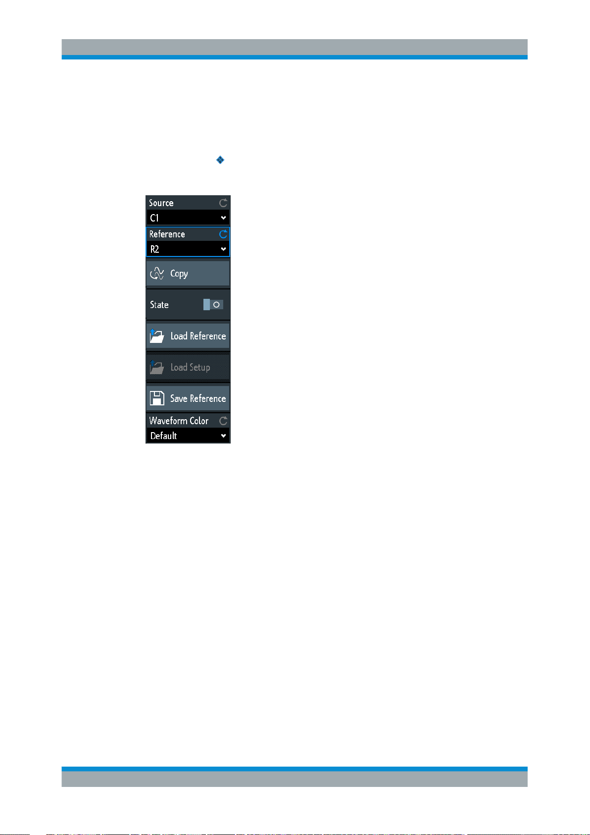
R&S®RTB2000
Waveform Analysis
Reference Waveforms
6.3.2 Settings for Reference Waveforms
► To open the "References" menu:
a)
Tap the
menu icon in the lower right corner of the screen.
b) Scroll down. Select "References".
Source...........................................................................................................................76
Reference......................................................................................................................76
Copy..............................................................................................................................77
State..............................................................................................................................77
Load Reference.............................................................................................................77
Load Setup....................................................................................................................77
Save Reference............................................................................................................ 77
Waveform Color............................................................................................................ 77
Source
Defines the source of the reference waveform. Any active channel, math or reference
waveform can be selected.
Remote command:
REFCurve<m>:SOURce on page 279
REFCurve<m>:SOURce:CATalog? on page 279
Reference
Selects one of the four possible reference waveforms.
76User Manual 1333.1611.02 ─ 03
Page 85

R&S®RTB2000
Waveform Analysis
Reference Waveforms
Copy
Copies the "Source" waveform to the selected reference waveform. The reference
waveform is kept until you update it or load another waveform to the reference.
Remote command:
REFCurve<m>:UPDate on page 280
State
Activates the reference waveform and displays it.
Remote command:
REFCurve<m>:STATe on page 279
Load Reference
Provides functions to load a reference waveform.
Select the "Location" of the waveform file (internal or USB), and the file. Tap "Load
Reference".
You can also delete obsolete files in the dialog box.
Remote command:
REFCurve<m>:LOAD on page 280
Load Setup
Loads the device settings that were used to obtain the stored reference waveform. The
settings are only available if the file was stored to the internal storage and never written
to a USB flash device.
Load the reference waveform first, and then the settings. If settings were not stored,
"Load Setup" is not active.
Remote command:
REFCurve<m>:LOAD:STATe on page 280
Save Reference
Opens a dialog box to save a waveform as reference waveform:
"Source"
"Destination"
"File Name"
"Comment"
"Save"
Remote command:
REFCurve<m>:SAVE on page 280
Select the waveform to be saved. You can save any active analog
channel, math or reference waveform, or logic pod.
Select the "Location" (internal directory or USB flash device), and the
target directory.
Enter the filename. If a file with the same filename already exists in
the destination directory, it will be overwritten without notification.
Optionally, enter text to describe the waveform.
Saves the data.
Waveform Color
Selects a color for the reference waveform. The default color is white. You can select
another monochrome color, or a color scale.
The color scales are described in "Waveform Color" on page 42.
77User Manual 1333.1611.02 ─ 03
Page 86

R&S®RTB2000
Waveform Analysis
History and Segmented Memory (Option R&S RTB-K15)
6.4 History and Segmented Memory (Option R&S RTB-
K15)
The option R&S RTB-K15, history and segmented memory, accesses the data of previously acquired waveforms and provides them for further analysis. Using this option,
you can analyze, for example, signals that occur in short bursts with long idle times,
packet communication on serial buses, radar pulses, and laser pulses. The option uses
the segmented memory to store the waveforms and provides a segment table to analyze the stored waveforms.
You can analyze history segments in the same way as the waveform of the latest
acquisition. All R&S RTB2000 measurement and analysis tools are available: zoom,
cursor measurements, quick and automatic measurements, mask test, serial protocol
analysis, mixed-signal functions and so on.
The segment table and the waveform data of history segments can be saved to file.
6.4.1 Segmented Memory
If an acquisition runs, the instrument stores the captured data in the memory, processes the data and displays the waveform. The segmented memory keeps the data of
the displayed waveform and also the data of the waveforms that have been captured
before. Each stored waveform is called a segment. The record length of the segments
can be defined. The number of segments depends on the record length. The shorter
the record length, the more segments can be saved.
Total memory 10 segments
4 waveforms acquired 4 segments
Segmented
-3
-1 0
-2
memory at
time = t
5
Discarded
earlier
waveforms
t
t
1
2
t
t
4
3
12 waveforms acquired 10 segments
-7
-9
-8
-6
-4
-5
-3
-1 0
-2
Segmented
memory at
time = t
13
t
t
1
2
Figure 6-2: Segmented memory. In this example, the memory can store 10 segments.
t
t
3
t
4
5
t
t
6
t
7
8
t
t
9
t
10
t
11
12
Each segment has a time stamp time to identify when the events took place.
The history can access the stored segments and display them. When you start a new
acquisition, the memory is cleared and the segments are written anew.
The history stores the following data during acquisition:
●
All active analog channels.
t
5
t
13
78User Manual 1333.1611.02 ─ 03
Page 87

R&S®RTB2000
Waveform Analysis
History and Segmented Memory (Option R&S RTB-K15)
●
All logic channels if at least one logic is active (with option R&S RTB-B1).
●
Decoded bus data if the bus is active (with at least one serial protocol option
R&S RTB-K1, -K2, or -K3).
To set the number of segments
1. Press the ACQUISITION key in the Horizontal area of the front panel.
2. Select the "Record Length". The number of available segments depends on the
record length.
See also: "Record Length" on page 50.
6.4.2 Segment Table
The memory segments are always written when an acquisition is running. When you
activate the history, the acquisition stops and the segment table opens. The segment
table shows the index and timestamp of all history segments, and also all functions to
view the segments that are stored in the memory.
The history segments store the data of the currently active channels. You can acquire
several channels at once, and display and analyze the channels individually.
To activate the history
1. Tap the "Menu" icon.
2. Select "History".
The acquisition stops, and the segment table is shown.
Run / Stop
Starts and stops the playback of the history segments.
Remote command:
...:HISTory:STATe
Prev.
Steps back to the next older segment.
79User Manual 1333.1611.02 ─ 03
Page 88

R&S®RTB2000
Waveform Analysis
History and Segmented Memory (Option R&S RTB-K15)
Next
Steps forward to the next newer segment.
Repeat
If selected, the playback of the selected history segments repeats automatically.
Remote command:
...:HISTory:REPLay
Speed
Sets the speed of the history playback: automatic, slow, middle, or fast.
Remote command:
...:HISTory:SPEed
Save
Saves the segment table to a CSV file. The file contains all timestamps: relative time,
time to previous, and absolute time. To save the waveform segments, use SAVE
LOAD key > "Waveforms".
See also: Chapter 6.4.4, "Exporting History Data", on page 81.
Remote command:
EXPort:ATABle:NAME on page 304
EXPort:ATABle:SAVE on page 304
Number
Accesses a particular history segment in the memory to display it. The newest acquisition segment has always the index "0". Older segments have a negative index. You
can also drag the slider, which is above the icons. The current segment is shown in the
index bar.
Remote command:
...:HISTory:CURRent
Time Format
Sets the format of the timestamp. The timestamp shows the time of the currently displayed history segment. Thus, the time relation between acquisitions is always available. More precisely, the timestamp is the time of the trigger event.
The timestamp can be absolute or relative:
●
Absolute: Date and daytime of the trigger event of the displayed segment.
Depending on the horizontal position, the waveform can be captured up to 100,000
seconds after the trigger event, and thus after the displayed timestamp. The instrument considers this delay automatically, all measurements are related to the trigger
event.
●
Relative: time difference of the current segment to the newest segment (index = 0).
Remote command:
Chapter 15.6.5.3, "Timestamps", on page 300
6.4.3 Displaying History Segments
You can show all history segments in sequence, or display a single segment.
80User Manual 1333.1611.02 ─ 03
Page 89

R&S®RTB2000
Waveform Analysis
History and Segmented Memory (Option R&S RTB-K15)
1. Activate the history.
2. Set the "Time Format" to be shown in the table: absolute or relative time.
3. Set the "Speed".
4. To play back all segments once, tap "Run".
5. To play back all segments repeatedly:
a) Enable the "Repeat" button.
b) Tap "Run".
6. To access a particular segment, you can:
● Tap the segment in the segment table.
● Drag the slider until the required segment number is shown.
● Tap "Number" and enter the segment number. The newest segment has
always the number "0". Older segments have a negative number.
● Use "Prev." and "Next" to show the adjacent segment.
7. If the history segments contain the data of several channels and you want to analyze only one or several channels, disable all channels that you do not need.
6.4.4 Exporting History Data
History segments can be saved to files on a USB flash drive even if the history is not
activate. You can select to save all visible channels, or one channel. In addition, you
can save the complete time information of the segment table.
6.4.4.1 Saving History to File
Before you can save history data, acquire the waveform and activate the history, so
that the segment table is visible.
To save the waveform history segments
1. Connect a USB flash drive to the instrument.
2. Press the SAVE LOAD key.
3. Select "Waveforms" in the menu.
4. Under "Points", select "History Data".
5. Under "Source", select whether you want to store all visible channels, or one of
them.
6. Enter the "File Name". This name is the name of the folder that contains the segment files.
The file format is CSV.
81User Manual 1333.1611.02 ─ 03
Page 90

R&S®RTB2000
Waveform Analysis
History and Segmented Memory (Option R&S RTB-K15)
7. To select the target folder, tap the "Destination" field.
The location is always "/USB_FRONT", saving to internal storage is not provided.
8. Tap "Save".
A message shows the progress of the saving process.
9. Close the dialog box.
To save the segment table
1. Connect a USB flash drive to the instrument.
2. In the segment table window, tap "Save".
3. To select the target folder, double-tap it.
4. Tap "New File".
5. Enter the filename.
6. Tap "Enter".
The file is saved immediately, and the window is closed.
6.4.4.2 File Organization and Content
The segment table and history segments are saved to CSV files.
Segment table
The segment table file contains all timestamps: relative time, time to previous, and
absolute time.
82User Manual 1333.1611.02 ─ 03
Page 91

R&S®RTB2000
Waveform Analysis
History and Segmented Memory (Option R&S RTB-K15)
Figure 6-3: Content of a segment table file
Waveforms
Each history segment is saved to a separate file, and all segment files are written to a
folder that contains only the files of the saved acquisition. You can specify the name of
the folder. The names of the data files include the segment index.
Figure 6-4: Content of a history waveform folder
The data files contain the time and voltage data of the samples. If you save all visible
channels, the voltages of all channels are written into one file.
Figure 6-5: Content of a history segment file, two channels are saved
83User Manual 1333.1611.02 ─ 03
Page 92

R&S®RTB2000
Waveform Analysis
Search
In addition to the data files, an index file is written. The index file delivers information
on the files and the segments. For each segment, the segment index, save date and
time, and the filename is listed.
Figure 6-6: Content of a history index file
6.5 Search
6.5.1 Search Conditions and Results
The search functions of R&S RTB2000 can find all edges, pulse widths, peaks, or
other events in an acquisition that match the search conditions. For each search type,
specific settings are available. Searches can be performed on channel, math or reference waveforms, available sources depend on the search type.
To configure the search
1. Press the SEARCH key.
2. Select the waveform that you want to search for events: "Source".
3. Select the event type that you want to find: "Search Type".
4. Configure the search conditions: "Setup".
The found events and the search conditions are shown in the result table at the bottom
of the display. The table shows the following result values: result number, time value,
and optional value depending on the search type (voltage, width).
During running acquisition, the results in the table are updated continuously, and the
events are marked at the top of the diagram by a brown triangle outline.
84User Manual 1333.1611.02 ─ 03
Page 93

R&S®RTB2000
Waveform Analysis
Search
Figure 6-7: Search results and settings during running acquisition
Remote commands to get search results:
●
SEARch:RCOunt? on page 295
●
SEARch:RESult:ALL? on page 294
●
SEARch:RESult<n>? on page 295
●
SEARch:RESDiagram:SHOW on page 294
●
SEARch:RESult:BCOunt? on page 294
To display search results
When the acquisition is stopped, you can browse the search results.
1. Stop the acquisition.
2. Tap the search result that you want to analyze. If necessary, scroll the list.
The selected event is marked by a filled triangle and a magnifying glass.
85User Manual 1333.1611.02 ─ 03
Page 94

R&S®RTB2000
Waveform Analysis
Search
3. In the "Search" menu, select "Track event".
The selected event is moved to the reference point. If you select another event, it is
shown at the same position.
To save search results
1. In the upper right corner of the search result table, tap the "Save" symbol.
2. Connect a USB flash drive if you want to save the data outside the instrument.
3. Select the correct "Destination" and the path.
You can also store the data on the instrument. Therefore, select the "Destination"
"/INT/SEARCH".
4. If necessary, change the filename and enter a comment.
86User Manual 1333.1611.02 ─ 03
Page 95

R&S®RTB2000
Waveform Analysis
Search
5. Tap "Save".
The data is saved to a CSV file.
6.5.2 General Search Settings
General search settings are independent of the search type. They are described in the
current section. The specific settings for individual search types are described in the
following sections.
► To open the "Search" menu, press the SEARCH key.
Search
Enables and disables the search mode.
Remote command:
SEARch:STATe on page 282
Search Type
Selects the event type you want to search for.
"Edge"
Similar to the edge trigger, an edge search result is found when the
waveform passes the given level in the specified direction.
For settings, see Chapter 6.5.3, "Edge Search", on page 89.
"Width"
The width search finds pulses with an exact pulse width, or pulses
shorter or longer than a given time, or pulses inside or outside the
given time range. It is similar to the width trigger.
For settings, see Chapter 6.5.4, "Width Search", on page 90.
"Peak"
The peak search finds pulses exceeding a given peak-to peak value.
For settings, see Chapter 6.5.5, "Peak Search", on page 91.
87User Manual 1333.1611.02 ─ 03
Page 96

R&S®RTB2000
Waveform Analysis
Search
"Rise/Fall time"
"Runt"
"Data2Clock"
"Pattern"
"Protocol"
Remote command:
SEARch:CONDition on page 282
The rise or fall time search finds slopes with an exact rise or fall time,
or rise/fall times shorter or longer than a given limit, or rise/fall times
inside or outside a given time range.
For settings, see Chapter 6.5.6, "Rise/Fall Time Search",
on page 91.
The runt search finds pulses lower than normal in amplitude. In addition, you can define a time limit for the runt.
For settings, see Chapter 6.5.7, "Runt Setup", on page 93.
The Data2Clock search - also known as setup/hold - finds violation of
setup and hold times. It analyzes the relative timing between two signals: a data signal and the synchronous clock signal.
For settings, see Chapter 6.5.8, "Data2Clock", on page 94.
The pattern search finds logical combinations of channel states inside
or outside a specified time range. For each channel, its state and
threshold level is defined. The states are combined logically, and the
time of true pattern results is compared with a specified time range.
For settings, see Chapter 6.5.9, "Pattern Search", on page 96.
The protocol search finds various events in decoded data serial signals. The events are protocol-specific and correspond to the trigger
settings of the serial protocol.
Source
Selects the waveform to be analyzed by search. Available sources depend on the
selected search type.
Edge, width and pattern search you can perform on analog and logic channels. Peak,
rise/fall and runt search are possible on active analog channels, math and reference
waveforms. For Data2Clock search, you need two active analog channels.
For protocol search, select the configured bus.
Remote command:
SEARch:SOURce on page 284
Setup
Opens a menu to define the search parameters for the selected search type.
Track event
If enabled, the selected result is moved to the reference point. Thus you can always
see the selected event in the diagram.
Save
Opens a dialog box to save the search results. The file format is CSV.
Remote command:
EXPort:SEARch:NAME on page 295
EXPort:SEARch:SAVE on page 296
88User Manual 1333.1611.02 ─ 03
Page 97

R&S®RTB2000
Waveform Analysis
Search
6.5.3 Edge Search
Similar to the edge trigger, an edge search result is found when the waveform passes
the given level in the specified direction.
► SEARCH > "Search Type" = "Edge" > "Setup"
Slope
Sets the slope to be found: rising, falling, or both slopes.
Remote command:
SEARch:TRIGger:EDGE:SLOPe on page 284
Level
Sets the voltage level for the search. To let the instrument set the level, tap "Find
Threshold".
Remote command:
SEARch:TRIGger:EDGE:LEVel on page 284
Hysteresis
Sets a hysteresis range to the search level to avoid unwanted search results caused
by noise oscillation around the level. To let the instrument set the hysteresis, tap "Find
Threshold".
For a rising edge, the hysteresis is below the search level. Otherwise, for a falling edge
the hysteresis is above the level.
Remote command:
SEARch:TRIGger:EDGE:LEVel:DELTa on page 284
Find Threshold
Analyzes the signal, sets the level to 50% of the signal amplitude, and also sets the
hysteresis.
89User Manual 1333.1611.02 ─ 03
Page 98

R&S®RTB2000
Waveform Analysis
Search
6.5.4 Width Search
The width search finds pulses with an exact pulse width, or pulses shorter or longer
than a given time, or pulses inside or outside the allowable time range. It is similar to
the width trigger.
► SEARCH > "Search Type" = "Width" > "Setup"
Polarity
Indicates the polarity of the pulse to be searched for.
Remote command:
SEARch:TRIGger:WIDTh:POLarity on page 285
Level
Sets the voltage level on which the pulse width is measured. To let the instrument set
the level, tap "Find Threshold".
Remote command:
SEARch:TRIGger:WIDTh:LEVel on page 285
Hysteresis
Sets a hysteresis range to the search level to avoid unwanted search results caused
by noise oscillation around the level. To let the instrument set the hysteresis, tap "Find
Threshold".
Remote command:
SEARch:TRIGger:WIDTh:LEVel:DELTa on page 285
Comparison
Sets the condition how the measured pulse width is compared with the given limits.
90User Manual 1333.1611.02 ─ 03
Page 99

R&S®RTB2000
Waveform Analysis
Search
The comparison works like the comparison of the width trigger, see Chapter 5.5,
"Width Trigger", on page 59.
Remote command:
SEARch:TRIGger:WIDTh:RANGe on page 285
Width
Sets the reference pulse width, the nominal value for comparisons.
Remote command:
SEARch:TRIGger:WIDTh:WIDTh on page 286
Variation
Sets a range Δt to the reference "Width" if comparison is set to "Equal" or "Not equal".
The instrument finds pulses inside or outside the range width ± Δt.
Remote command:
SEARch:TRIGger:WIDTh:DELTa on page 286
6.5.5 Peak Search
The peak search finds pulses exceeding a given peak-to-peak value (magnitude).
► SEARCH > "Search Type" = "Peak" > "Setup"
Polarity
Indicates the polarity of the pulse to be searched for a peak.
Remote command:
SEARch:MEASure:PEAK:POLarity on page 286
Magnitude
Sets the peak-to-peak limit. If the signal exceeds this limit, a search event is listed.
Remote command:
SEARch:MEASure:LEVel:PEAK:MAGNitude on page 287
6.5.6 Rise/Fall Time Search
The rise or fall time search finds slopes with an exact rise or fall time, or rise/fall times
shorter or longer than a given limit, or rise/fall times inside or outside the allowable time
range.
91User Manual 1333.1611.02 ─ 03
Page 100

R&S®RTB2000
Waveform Analysis
Search
► SEARCH > "Search Type" = "Rise/Fall Time" > "Setup"
Edge
Sets the slope to be found:
●
"Rising" to search for rise time
●
"Falling" to search for fall time
●
"Both" to search for rise and fall time
Remote command:
SEARch:TRIGger:RISetime:SLOPe on page 287
Upper level, Lower level
Set the upper and lower voltage thresholds. When the signal crosses the first level, the
rise/fall time measurement starts. It stops when the signal crosses the second level. To
let the instrument set the levels, tap "Find Threshold".
Remote command:
SEARch:TRIGger:LEVel:RISetime:LOWer on page 287
SEARch:TRIGger:LEVel:RISetime:UPPer on page 287
Comparison
Sets how the measured rise or fall time is compared with the given limits.
"Greater than"
"Lower than"
"Equal"
"Not equal"
Finds rise/fall times longer than the given "Rise/Fall Time".
Finds rise/fall times shorter than the given "Rise/Fall Time".
Finds rise/fall times equal to the reference "Rise/Fall Time" if "Varia-
tion" Δt = 0.
If "Variation" ≠ 0, the setting finds rise/fall times within the range time
± Δt.
Finds rise/fall times unequal to the reference value if "Variation" Δt =
0.
If "Variation" ≠ 0, the setting finds rise/fall times outside the range
time ± Δt.
92User Manual 1333.1611.02 ─ 03
 Loading...