

Page 1
Migrating PanelView Enhanced Terminal Applications
Quick Start
Page 2
Important User Information
Solid state equipment has operational characteristics differing from those of
electromechanical equipment. Safety Guidelines for the Application,
Installation and Maintenance of Solid State Controls (publication SGI-1.1
available from your local Rockwell Automation sales office or online at
http://literature.rockwellautomation.com
) describes some important
differences between solid state equipment and hard-wired electromechanical
devices. Because of this difference, and also because of the wide variety of
uses for solid state equipment, all persons responsible for applying this
equipment must satisfy themselves that each intended application of this
equipment is acceptable.
In no event will Rockwell Automation, Inc. be responsible or liable for
indirect or consequential damages resulting from the use or application of
this equipment.
The examples and diagrams in this manual are included solely for illustrative
purposes. Because of the many variables and requirements associated with
any particular installation, Rockwell Automation, Inc. cannot assume
responsibility or liability for actual use based on the examples and diagrams.
No patent liability is assumed by Rockwell Automation, Inc. with respect to
use of information, circuits, equipment, or software described in this manual.
Reproduction of the contents of this manual, in whole or in part, without
written permission of Rockwell Automation, Inc., is prohibited.
Throughout this manual, when necessary, we use notes to make you aware
of safety considerations.
WARNING
Identifies information about practices or circumstances that can cause
an explosion in a hazardous environment, which may lead to personal
injury or death, property damage, or economic loss.
IMPORTANT
ATTENTION
Identifies information that is critical for successful application and
understanding of the product.
Identifies information about practices or circumstances that can lead
to personal injury or death, property damage, or economic loss.
Attentions help you identify a hazard, avoid a hazard, and recognize
the consequence
SHOCK HAZARD
Labels may be on or inside the equipment, for example, a drive or
motor, to alert people that dangerous voltage may be present.
BURN HAZARD
Labels may be on or inside the equipment, for example, a drive or
motor, to alert people that surfaces may reach dangerous
temperatures.
Allen-Bradley, CompactLogix, DH+, FactoryTalk, FactoryTalk View Machine Edition, FactoryTalk View ME, FactoryTalk Site
Edition, FactoryTalk View Studio, PanelBuilder, PanelView, PanelView e, PanelView Plus, PLC 5, Rockwell Automation, RSLinx,
RSLinx, RSLinx Lite, RSView, SLC, SLC 500, and TechConnect are trademarks of Rockwell Automation, Inc.
Trademarks not belonging to Rockwell Automation are property of their respective companies.
Page 3
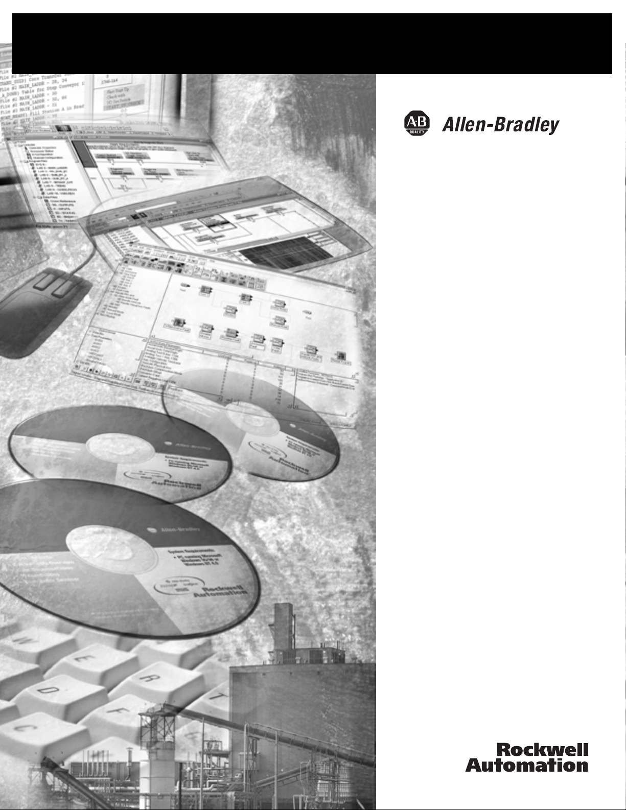
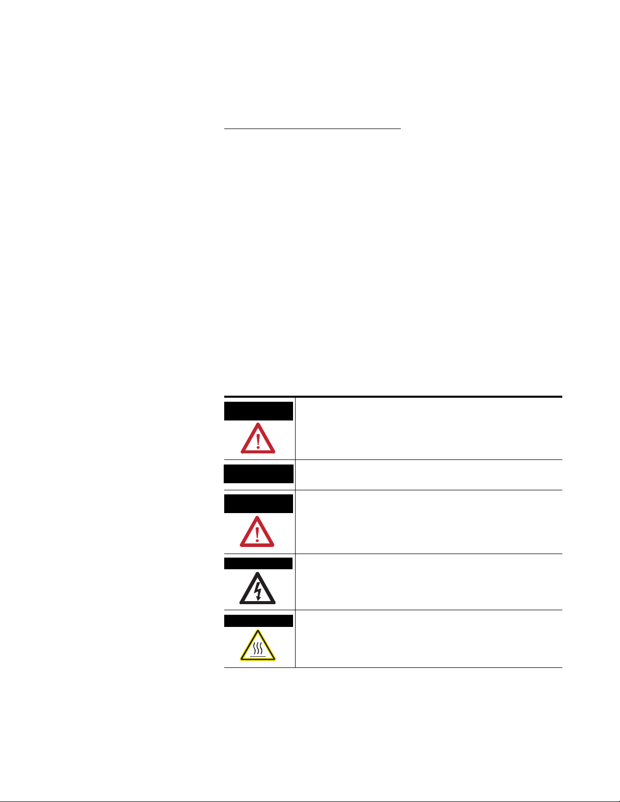
We Can Get You From Here...
Where to Start
PanelView 1400e Terminal
...To Here
SLC 500 Controller
PLC-5 Controller
PanelView Plus Terminal
SLC 500 Controller
3Publication 2711P-QS001A-EN-P - October 2007 3
L
C
P
o
l
l
e
5
-
r
o
C
n
r
t
Page 4
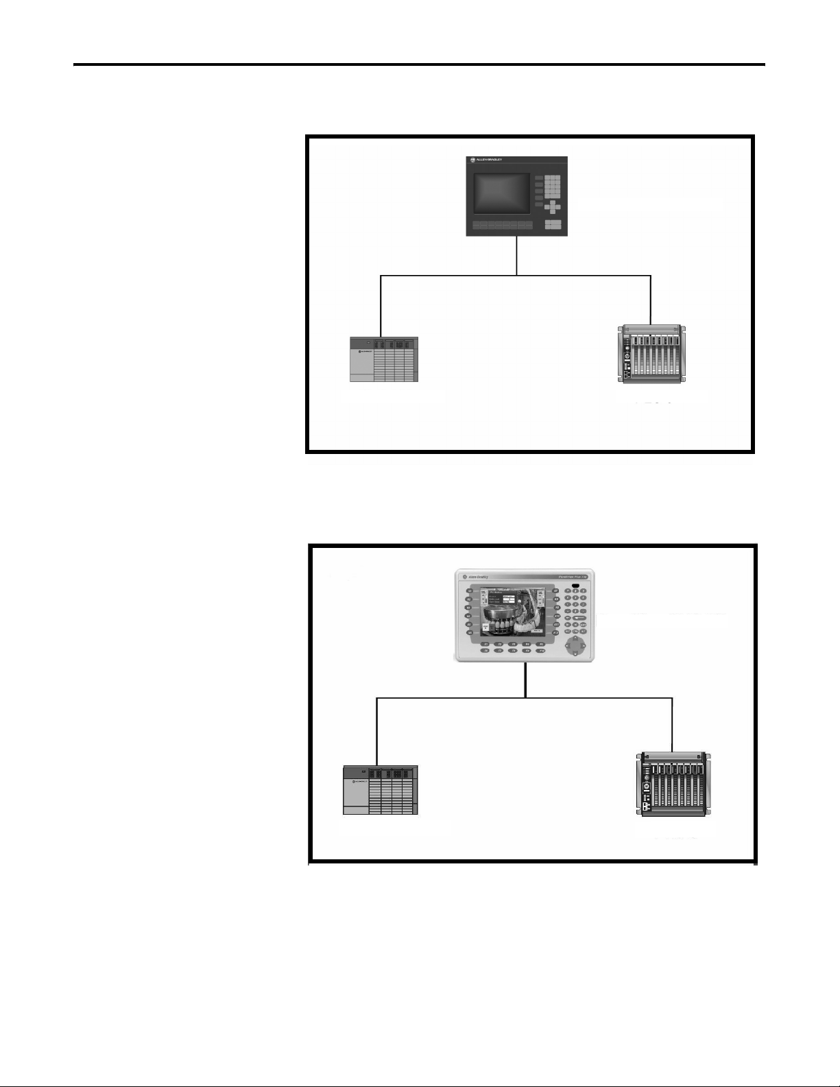
Where to Start
Follow this path to migrate your PanelView 1000e or 1400e terminal
and application to the PanelView Plus terminal platform.
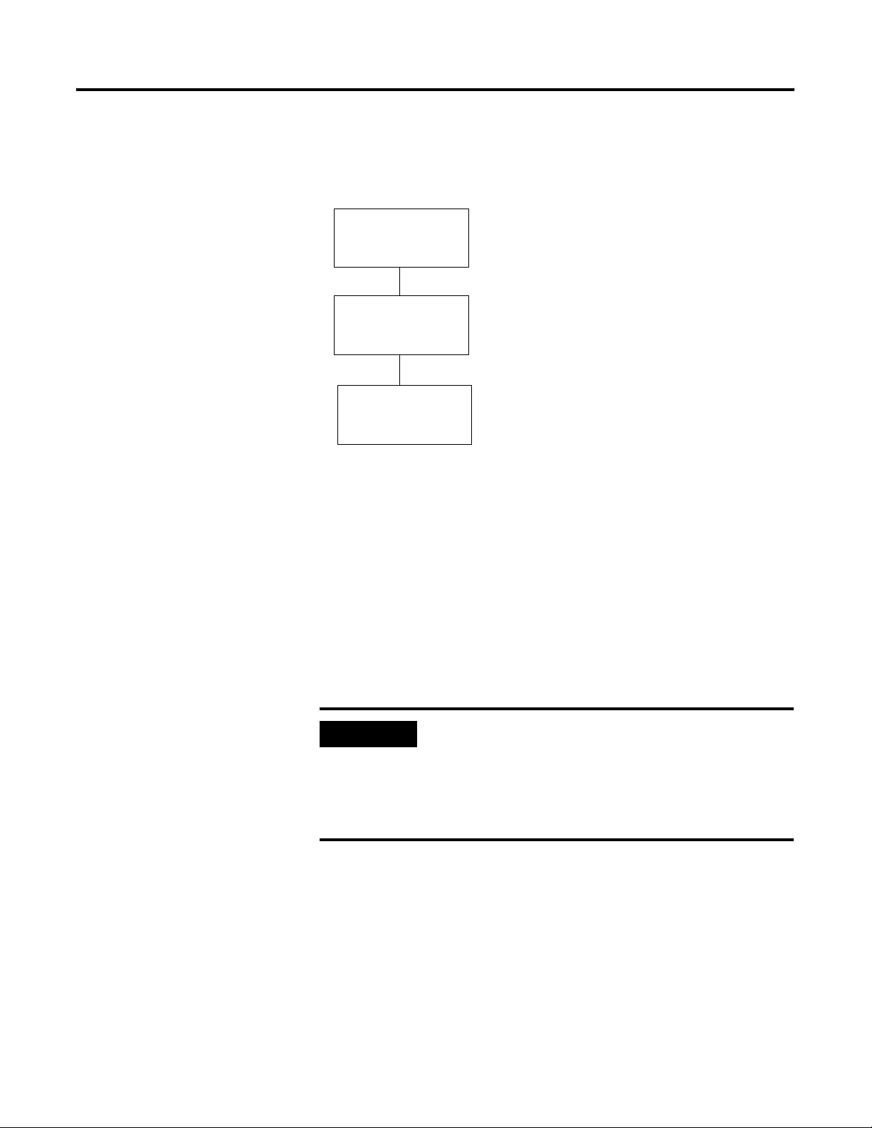
Chapter 1
Migration Considerations
Chapter 2
Select a Terminal
Replacement
Chapter 3
Migrate Your Application
Chapter 4
Review the Application
Conversion Log
Chapter 5
Review Object Mapping
Chapter 6
Review Unsupported
Features and Implement
Workarounds for Migration
Issues
Chapter 7
Qualify the Runtime
Application
Chapter 8
Create the Runtime
Application
Chapter 9
Measure and Improve
Application Runtime
Performance
Before updating the migrated application,
review the conversion log details and the
remaining chapters. If you determine that
the conversion operation would not be
feasible, you can use the conversion
services provided by Rockwell
Automation. For more information, see
the Conversion Services, publication
GMSC10-PP016
Appendix A
Advanced Object Editing
.
4 Publication 2711P-QS001A-EN-P - October 2007
Page 5

Table of Contents
Preface
Migration Considerations
Select a Terminal Replacement
Introduction . . . . . . . . . . . . . . . . . . . . . . . . . . . . . . . . . . . . . 9
Audience . . . . . . . . . . . . . . . . . . . . . . . . . . . . . . . . . . . . . . 10
Required Software. . . . . . . . . . . . . . . . . . . . . . . . . . . . . . . . 10
Migration Services . . . . . . . . . . . . . . . . . . . . . . . . . . . . . . . . 10
Conventions . . . . . . . . . . . . . . . . . . . . . . . . . . . . . . . . . . . . 11
Additional Resources. . . . . . . . . . . . . . . . . . . . . . . . . . . . . . 11
Chapter 1
Introduction . . . . . . . . . . . . . . . . . . . . . . . . . . . . . . . . . . . . 13
Migration Considerations. . . . . . . . . . . . . . . . . . . . . . . . . . . 13
Chapter 2
Introduction . . . . . . . . . . . . . . . . . . . . . . . . . . . . . . . . . . . . 15
Before You Begin . . . . . . . . . . . . . . . . . . . . . . . . . . . . . . . . 15
What You Need . . . . . . . . . . . . . . . . . . . . . . . . . . . . . . . . . 15
Follow These Steps . . . . . . . . . . . . . . . . . . . . . . . . . . . . . . . 15
Selecting a Terminal Replacement . . . . . . . . . . . . . . . . . . . . 16
Reviewing Terminal Comparisons . . . . . . . . . . . . . . . . . . . . 17
Installing a PanelView Plus Terminal . . . . . . . . . . . . . . . . . . 18
Migrate Your Application
Review the Application
Conversion Log
Review Object Mapping
Chapter 3
Introduction . . . . . . . . . . . . . . . . . . . . . . . . . . . . . . . . . . . . 19
Before You Begin . . . . . . . . . . . . . . . . . . . . . . . . . . . . . . . . 19
What You Need . . . . . . . . . . . . . . . . . . . . . . . . . . . . . . . . . 19
Follow These Steps . . . . . . . . . . . . . . . . . . . . . . . . . . . . . . . 20
Import Application . . . . . . . . . . . . . . . . . . . . . . . . . . . . . . . 21
Chapter 4
Introduction . . . . . . . . . . . . . . . . . . . . . . . . . . . . . . . . . . . . 25
Before You Begin . . . . . . . . . . . . . . . . . . . . . . . . . . . . . . . . 25
What You Need . . . . . . . . . . . . . . . . . . . . . . . . . . . . . . . . . 25
Follow These Steps . . . . . . . . . . . . . . . . . . . . . . . . . . . . . . . 26
About the Conversion Log. . . . . . . . . . . . . . . . . . . . . . . . . . 26
Open the Conversion Log . . . . . . . . . . . . . . . . . . . . . . . . . . 27
Review the Conversion Log . . . . . . . . . . . . . . . . . . . . . . . . . 28
Chapter 5
Introduction . . . . . . . . . . . . . . . . . . . . . . . . . . . . . . . . . . . . 33
Before You Begin . . . . . . . . . . . . . . . . . . . . . . . . . . . . . . . . 33
What You Need . . . . . . . . . . . . . . . . . . . . . . . . . . . . . . . . . 33
Follow These Steps . . . . . . . . . . . . . . . . . . . . . . . . . . . . . . . 34
Reviewing Object Mapping . . . . . . . . . . . . . . . . . . . . . . . . . 35
Reviewing and Modifying Expressions . . . . . . . . . . . . . . . . . 37
5Publication 2711P-QS001A-EN-P - October 2007 5
Page 6

Table of Contents
Review Unsupported Features and
Implement Workarounds for
Migration Issues
Chapter 6
Introduction . . . . . . . . . . . . . . . . . . . . . . . . . . . . . . . . . . . . 39
Before You Begin . . . . . . . . . . . . . . . . . . . . . . . . . . . . . . . . 39
What You Need . . . . . . . . . . . . . . . . . . . . . . . . . . . . . . . . . 39
Follow These Steps . . . . . . . . . . . . . . . . . . . . . . . . . . . . . . . 40
Reviewing Unsupported Features. . . . . . . . . . . . . . . . . . . . . 41
Reviewing Common Migration Issues and Workarounds. . . . 46
Required Files and Utilities . . . . . . . . . . . . . . . . . . . . . . . . . 46
Replacing Scrolling List Objects . . . . . . . . . . . . . . . . . . . . . . 47
Replacing the Cursor List. . . . . . . . . . . . . . . . . . . . . . . . . . . 48
Create a Piloted Control List Selector . . . . . . . . . . . . . . . 48
Retain Last State. . . . . . . . . . . . . . . . . . . . . . . . . . . . . . . 52
Resize the Piloted Control List Selector . . . . . . . . . . . . . . 53
Assign Navigation Keys to Piloted Control List Selector . . 53
Assign Function Keys to a Piloted Control List Selector . . 55
Replacing the Multistate Indicator Object List . . . . . . . . . . . . 56
Create Multistate Indicators. . . . . . . . . . . . . . . . . . . . . . . 56
Resize and Align Multistate Indicators . . . . . . . . . . . . . . . 59
Replacing the Local Message Object List. . . . . . . . . . . . . . . . 60
Create Local Message Displays . . . . . . . . . . . . . . . . . . . . 60
Resize and Align the Local Message Displays . . . . . . . . . 63
Replacing the Numeric Data Display Object List . . . . . . . . . . 64
Create Numeric Displays . . . . . . . . . . . . . . . . . . . . . . . . 64
Resize and Align the Numeric Displays . . . . . . . . . . . . . . 67
Replacing the Set Bit Cursor Point Object. . . . . . . . . . . . . . . 68
Register the ActiveX Control on Your Computer. . . . . . . 68
Configure the Set Bit Cursor Point ActiveX Control . . . . . 71
Migrate the Set Bit Cursor Point Object . . . . . . . . . . . . . . 72
Provide Visual Feedback . . . . . . . . . . . . . . . . . . . . . . . . 76
Register the ActiveX Control on a PanelView CE Terminal 79
Bit Position Data Type Workaround. . . . . . . . . . . . . . . . . . . 80
PLC Controlled Decimal Point Workaround . . . . . . . . . . . . . 81
Fixed Position Decimal Point Workaround . . . . . . . . . . . . . . 82
Retain Last State Workaround . . . . . . . . . . . . . . . . . . . . . . . 83
Ladder Logic Updates to Support Visible States. . . . . . . . . . . 86
Chapter 7
Qualify the Runtime Application
6 Publication 2711P-QS001A-EN-P - October 2007
Introduction . . . . . . . . . . . . . . . . . . . . . . . . . . . . . . . . . . . . 91
Before You Begin . . . . . . . . . . . . . . . . . . . . . . . . . . . . . . . . 91
What You Need . . . . . . . . . . . . . . . . . . . . . . . . . . . . . . . . . 91
Follow These Steps . . . . . . . . . . . . . . . . . . . . . . . . . . . . . . . 92
Reviewing Diagnostic Lists. . . . . . . . . . . . . . . . . . . . . . . . . . 93
Configure the Runtime Diagnostic Display . . . . . . . . . . . . . . 94
Reviewing Error States for Graphic Objects . . . . . . . . . . . . . 95
Test Run Graphic Displays . . . . . . . . . . . . . . . . . . . . . . . . . 96
Page 7

Create the Runtime Application
Table of Contents
Test Run the Application . . . . . . . . . . . . . . . . . . . . . . . . . . . 98
Configuring Global Memory Connections. . . . . . . . . . . . . . . 99
Hardware Limitations . . . . . . . . . . . . . . . . . . . . . . . . . . . 99
Configure Global Connections . . . . . . . . . . . . . . . . . . . 100
Configuring Communication . . . . . . . . . . . . . . . . . . . . . . . 102
Remote I/O Communication. . . . . . . . . . . . . . . . . . . . . 102
Configure DH+ Communication . . . . . . . . . . . . . . . . . . 106
ControlNet Communications. . . . . . . . . . . . . . . . . . . . . 109
Chapter 8
Introduction . . . . . . . . . . . . . . . . . . . . . . . . . . . . . . . . . . . 111
Before You Begin . . . . . . . . . . . . . . . . . . . . . . . . . . . . . . . 111
What You Need . . . . . . . . . . . . . . . . . . . . . . . . . . . . . . . . 111
Follow These Steps . . . . . . . . . . . . . . . . . . . . . . . . . . . . . . 112
Create the Runtime Application . . . . . . . . . . . . . . . . . . . . . 113
Download the Runtime Application . . . . . . . . . . . . . . . . . . 114
Download Application Using Ethernet Connection . . . . 114
Download Application Using a CompactFlash Card . . . . 118
Run the Application . . . . . . . . . . . . . . . . . . . . . . . . . . . . . 120
Measure and Improve Runtime
Application Performance
Chapter 9
Introduction . . . . . . . . . . . . . . . . . . . . . . . . . . . . . . . . . . . 121
Before You Begin . . . . . . . . . . . . . . . . . . . . . . . . . . . . . . . 121
What You Need . . . . . . . . . . . . . . . . . . . . . . . . . . . . . . . . 121
Follow These Steps . . . . . . . . . . . . . . . . . . . . . . . . . . . . . . 122
Benchmarking Performance. . . . . . . . . . . . . . . . . . . . . . . . 123
Reviewing Tag Update Response . . . . . . . . . . . . . . . . . . . . 123
Scan Classes - PanelBuilder 1400E Software . . . . . . . . . 123
Tag Update Rate - FactoryTalk View ME Software . . . . . 124
Measure Performance of Display Changes . . . . . . . . . . . . . 125
Reviewing Background Updates . . . . . . . . . . . . . . . . . . . . 126
Global Connections . . . . . . . . . . . . . . . . . . . . . . . . . . . 126
Alarms. . . . . . . . . . . . . . . . . . . . . . . . . . . . . . . . . . . . . 127
Data Log Model . . . . . . . . . . . . . . . . . . . . . . . . . . . . . . 128
Information Messages. . . . . . . . . . . . . . . . . . . . . . . . . . 129
Optimize Tags for Communication Protocols . . . . . . . . . . . 129
About the Tag Converter Wizard . . . . . . . . . . . . . . . . . 130
Export the HMI Tag Database. . . . . . . . . . . . . . . . . . . . 131
Export Graphic Displays to XML File . . . . . . . . . . . . . . 133
Export Alarms to XML File . . . . . . . . . . . . . . . . . . . . . . 135
Run the Tag Converter Wizard . . . . . . . . . . . . . . . . . . . 137
Re-import the Display XML File . . . . . . . . . . . . . . . . . . 141
Re-import the Alarms XML File . . . . . . . . . . . . . . . . . . . 144
Publication 2711P-QS001A-EN-P - October 2007 7
Page 8

Table of Contents
Advanced Object Editing
Appendix A
Introduction . . . . . . . . . . . . . . . . . . . . . . . . . . . . . . . . . . . 147
Property Panel . . . . . . . . . . . . . . . . . . . . . . . . . . . . . . . . . 147
Editing Multiple Objects . . . . . . . . . . . . . . . . . . . . . . . . . . 148
Object Explorer. . . . . . . . . . . . . . . . . . . . . . . . . . . . . . . . . 150
Tag Substitution . . . . . . . . . . . . . . . . . . . . . . . . . . . . . . . . 154
Index
8 Publication 2711P-QS001A-EN-P - October 2007
Page 9

Preface
Introduction
This document provides guidelines and procedures for migrating a
PanelView 1000e or 1400e terminal application to the PanelView Plus
terminal platform. The procedures and guidelines cover:
• selecting and optionally installing a PanelView Plus terminal
replacement.
• migrating your PanelView 1000e or 1400e application to
FactoryTalk View Machine Edition software.
• updating the migrated application and ladder logic, as
necessary, to verify compatibility with FactoryTalk View
Machine Edition software.
• reviewing and implementing workarounds for unsupported
features.
• verifying the correct operation of the migrated application on
the PanelView Plus terminal.
• measuring and improving performance of the migrated
application.
The procedures and guidelines are designed to make the migration
process as easy as possible.
The beginning of most chapters contains the following information.
Read these sections carefully before beginning work in each chapter.
• Before You Begin - This section lists the steps that must be
completed and decisions that must be made before starting the
chapter. The chapters in this quick start must be completed or
reviewed in the order in which they appear.
• What You Need - This section lists the items that are required to
complete the steps in the current chapter. This includes, but is
not limited, to hardware and software.
• Follow These Steps - This section illustrates the path or steps in
the current chapter.
Also note that the electronic version of this publication contains links
to other publications for easier navigation and reference.
9Publication 2711P-QS001A-EN-P - October 2007 9
Page 10
Preface Preface
Audience
This quick start was created to assist a user familiar with Rockwell
Automation HMI products on how to convert an existing application
for the PanelView Plus terminal platform.
Required Software
The table provides the software required to convert a PanelView
1000e or 1400e application to a PanelView Plus application.
Software Version
FactoryTalk View Studio, which
includes:
• FactoryTalk View Machine Edition
• RSLinx Enterprise
PanelBuilder 1400e Software Version 5.16
Version 5.0
Migration Services
This migration service Includes For more information
Step Forward Program Provides a credit for returned product.
• PanelView 1400e to PanelView 1000e
• PanelView Enhanced to PanelView Plus
PV1000e Migration Kits PV1000e terminal and adapter plate at a
reduced price
Consult your local distributor for details
Consult your local distributor for details
PanelView Plus Starter Kits PanelView Plus terminal and associated
software at a reduced price to help you get
started with a new product family.
Bundled Migration Services • PanelView Enhanced to PanelView Plus
terminal hardware conversion
• PanelView Enhanced to PanelView Plus
application file conversion
• Turnkey service including any ladder
logic changes required
• Delivered onsite by Rockwell
Automation service engineers
• Project supervision and conversion
engineering services
• Standardized service bundle
• Fixed price proposal
10 Publication 2711P-QS001A-EN-P - October 2007
Consult your local distributor for details
For more information on services, go to this
website:
http:\\rockwellautomation.com/services/on
site
Page 11
Preface Preface
Conventions
This manual uses the following conventions.
Convention Meaning Example
Courier
font
Check or uncheck Click to activate or deactivate a checkbox. Check the Disable Keying checkbox.
Click
Type or enter text exactly as shown. Type cmd.
Click the left mouse button once while the cursor is positioned
on object or selection.
Click Browse.
Double-click
Expand
Right-click
Select Click to highlight a menu item or list choice. Select the SBCP ActiveX file.
> Shows nested menu selections as menu name followed by menu
Click the left mouse button twice in quick succession while the
cursor is positioned on object or selection.
Click the + to the left of a given item /folder to show its
contents.
Click the right mouse button once while the cursor is positioned
on object or selection.
selection.
Double-click the application icon.
Expand HMI tags.
Right-click on Program Files.
Select Object>ActiveX Control.
Additional Resources
Resource Description
Adapter Kit for PanelView 1400e Touch Screen Terminal
Cutout Installation Instructions, publication 2711-IN023
Adapter Kit for PanelView 1200/1200e/1400e Keypad
Terminal Cutout installation instructions, publication
2711P-IN015
Provides details on how to use the cutout adapter kit, catalog number
2711P-RAT12E, to mount a PanelView Plus or PanelView Plus CE 1250 touch
screen terminal into an existing PanelView 1400e touch screen panel cutout.
Provides details on how to use the cutout adapter kit, catalog number
2711P-RAK12E, to mount a PanelView Plus or PanelView Plus CE 1250 keypad
terminal into an existing PanelView 1400e keypad panel cutout.
Adapter Kit for PanelView Standard or PanelView e
Terminal Cutouts Installation Instructions, publication
2711P-IN010
PanelView Plus Terminals and Display Modules
Installation Instructions, publication 2711P-IN001
Visualization Platforms Selection guide, publication
VIEW-SG001
FactoryTalk View Studio online help Provides information and procedures for creating and editing a FactoryTalk
Publication 2711P-QS001A-EN-P - October 2007 11
Provides details on how to use the:
• cutout adapter kit, cat. no. 2711P-RAK10, to mount a PanelView Plus or
PanelView Plus CE 1000 keypad terminal into an existing PanelView 1000e
keypad panel cutout.
• cutout adapter kit, cat. no. 2711P-RAT10, to mount a PanelView Plus or
PanelView Plus CE 1000 touch screen terminal into an existing PanelView
1000e touch screen, panel cutout.
Provides details on how to install the PanelView Plus 1250 or 1500 terminal in
a panel.
Provides catalog numbers for the PanelView Plus terminals.
View Machine Edition application and supported features.
Page 12

Preface Preface
12 Publication 2711P-QS001A-EN-P - October 2007
Page 13

Migration Considerations
Chapter
1
Introduction
Migration Considerations
Migration Consideration Explanation For More Information
Application reuse? Do you need to reuse your PanelView 1000e or 1400e
Use multiple RIO racks? Does your application require more than one rack of discrete
Require relay or beeper? Does your application use a built-in alarm relay or beeper? The
This chapter covers considerations to address before migrating a
PanelView 1000e or 1400e application to the PanelView Plus platform.
The table provides an explanation of things to consider when
migrating an application.
Reviewing Object Mapping,
application and PLC ladder logic? If so, you can convert your
application for a PanelView Plus terminal using FactoryTalk
View Machine Edition (ME) software. The application and PLC
ladder logic may require updates because some objects or
features may not directly migrate to FactoryTalk View ME
software.
If you do not want to reuse your current application but instead
create a new one with FactoryTalk View ME software, you can
stop here.
Remote I/O? The PanelView Plus terminals support multiple
racks of discrete Remote I/O, depending on the scanner type.
PanelView Plus terminals do not support a built-in alarm relay
or beeper. However, you can use an external alarm relay.
page 35
Reviewing and Modifying
Expressions, page 37
Reviewing Unsupported
Features, page 41
Reviewing Terminal
Comparisons, page 17
13Publication 2711P-QS001A-EN-P - October 2007 13
Page 14

Chapter 1 Migration Considerations
Migration Consideration Explanation For More Information
Required enhanced features? Does your application require enhanced features? If so, you
can take advantage of the advanced features offered by the
PanelView Plus terminals.
• Functions: trending, data logging, alarming,
information and local messages, expressions, security,
language switching, recipes, global objects,
multiversion support, face plates, graphic libraries,
parameter files, rich graphics, and animation.
• Communication: Ethernet, ControlNet, DeviceNet,
DHPlus, Remote I/O, and third party PLC connectivity.
• Hardware: Analog resistive touchscreen, x86
processor, up to 128 MB of application memory,
modular display, communication, and logic
components, USB support, high-bright display, and
stainless steel bezel options.
• Remote connectivity: FTP, Web server, VNC, remote
desktop. Applies only to PanelView Plus CE terminals.
• Other: Adobe PDF, PowerPoint, Word, Excel, and MPEG
viewers, Internet Explorer (full-featured), various
ActiveX controls. Applies only to PanelView Plus CE
terminals.
What are the terminal
replacement options?
The terminal replacement options for the PanelView 1000e
and 1400e terminals are the PanelView Plus 1250 or 1500
Selecting a Terminal
Replacement, page 16
terminals.
The rest of this document steps you through the process of selecting a
replacement terminal, migrating, and testing the application.
14 Publication 2711P-QS001A-EN-P - October 2007
Page 15

Select a Terminal Replacement
Chapter
2
Introduction
Before You Begin
What You Need
Follow These Steps
In this chapter, you will select and optionally install a PanelView Plus
terminal replacement for your PanelView 1000e or 1400e terminal.
Review the migration considerations table (chapter 1).
Nothing is required.
Follow these steps to select a PanelView Plus 1250 or 1500 terminal as
a replacement for your PanelView ‘e’ terminal.
Selecting a Terminal
Replacement
Page 16
Reviewing Terminal
Comparisons
Page 16
Installing a PanelView
Plus Terminal
Page 18
15Publication 2711P-QS001A-EN-P - October 2007 15
Page 16

Chapter 2 Select a Terminal Replacement
Selecting a Terminal
Replacement options for the PanelView 1000e and 1400e terminals
include the PanelView Plus or PanelView Plus CE 1250 and 1500
Replacement
terminals. Some of the PanelView Plus terminals fit directly into the
existing panel cutout of the PanelView ‘e’ terminals; others will
require an adapter plate.
PanelView Plus Replacement Terminals
For this PanelView ‘e’ terminal Select one of these replacement terminals Adapter Plate
Required
PanelView 1000e touch screen PanelView Plus 1250 touch screen
PanelView Plus CE 1250 touch screen
(1)
PanelView 1000e keypad PanelView Plus 1250 keypad or keypad and touch
PanelView Plus CE 1250 keypad or keypad and touch
PanelView 1400e touch screen PanelView Plus 1250 touch screen
PanelView Plus CE 1250 touch screen
(1)
PanelView Plus 1500 touch screen
PanelView Plus CE 1500 touch screen
(1)
PanelView 1400e keypad PanelView Plus 1250 keypad or keypad and touch
PanelView Plus CE 1250 keypad or keypad and touch
PanelView Plus 1500 keypad or keypad and touch
PanelView Plus CE 1500 keypad or keypad and touch
(1)
The PanelView Plus CE terminal is required if your application requires the set bit cursor point function.
(2)
The PanelView Plus or PanelView Plus CE 1500 terminal will fit in the existing PanelView 1400e panel cutout. The adapter plate is required only to cover the stud
mounting holes.
No —
No —
(1)
Yes
(2)
Yes
Yes 2711P-RAK12E
(1)
(2)
Yes
(1)
Adapter Plate
Cat. No.
2711P-RAT12E
2711P-RAT15
2711P-RAK15
16 Publication 2711P-QS001A-EN-P - October 2007
Page 17
Select a Terminal Replacement Chapter 2
Reviewing Terminal
Review dimensions and other pertinent information comparing the
PanelView 1000e and 1400e keypad and touch terminals with the
Comparisons
equivalent PanelView Plus or PanelView Plus CE 1250 or 1500
terminals.
The PanelView Plus 1250 and 1500 terminals are available as
preconfigured units or separate modular components. The catalog
numbers of the preconfigured units are specific to operator input,
display size, communication, power, and memory requirements.
For a list of valid catalog numbers for preconfigured units or modular
components of the PanelView Plus terminals, refer to this website:
http://www.ab.com/catalogs/
Touch Screen Terminal Comparisons
Attribute PanelView 1000e
Cat. No. 2711e-T10C6
Depth, approx. 157 mm (6.18 in.) 404 mm (15.9 in.)
Panel cutout, H x W 257 x 338 mm
10.11 x 13.29 in.
Alarm relay 24V ac, 1 A
24V dc, 1 A
PanelView 1400e
Cat. No. 2711e-T14C6
326 x 391 mm
12.85 x 15.375 in.
250V ac, 18A
30V dc, 8 A
PanelView Plus 1250
Cat. No. 2711P-T12Cxxx
55 mm (2.18 in.)
257 x 338 mm
10.11 x 13.29 in.
Requires external relay Requires external relay
(1)
PanelView Plus 1500
Cat. No. 2711P-T15Cxxx
65 mm (2.55 in.)
305 x 391 mm
12.0 x 15.4 in.
(1)
Display 10.4 in. VGA
TFT flat panel display
Operator input Touch screen Touch screen Touch screen Touch screen
(1)
Optional add-on communication modules will increase the overall depth of the product.
Keypad Terminal Comparisons
Attribute PanelView 1000e
Cat. No. 2711e-K10C6
Depth, approx. 156 mm (6.15 in.) 404 mm (15.9 in.)
Panel cutout, H x W 257 x 390 mm
10.11 x 15.35 in.
Alarm relay 24V ac, 1 A
24V dc, 1 A
Display 10.4 in. VGA
TFT flat panel display
Operator input Keypad Keypad Keypad Keypad
(1)
Optional add-on communication modules will increase the overall depth of the product.
14.0 in. VGA/SVGA
CRT
PanelView 1400e
Cat. No. 2711e-K14C6
326 x 429 mm
12.85 x 16.90 in.
250V ac, 8 A
30V dc, 8 A
14.0 in. VGA/SVGA
CRT
12.1 in. SVGA
TFT flat panel display
PanelView Plus 1250
Cat. No. 2711P-K15Cxxx
55 mm (2.18 in.)
257 x 390 mm
10.11 x 15.35 in.
Requires external relay Requires external relay
12.1 in. SVGA
TFT flat panel display
(1)
15.1 in. SVGA
TFT flat panel display
PanelView Plus 1500
Cat. No. 2711P-K15xxx
65 mm (2.55 in.)
305 x 419 mm
12.0 x 16.5 in.
15.1 in. SVGA
TFT flat panel display
(1)
Publication 2711P-QS001A-EN-P - October 2007 17
Page 18

Chapter 2 Select a Terminal Replacement
Installing a PanelView Plus Terminal
Install the selected PanelView Plus 1250 or 1500 terminal into the
existing PanelView 1000e or 1400e panel cutout. You may need an
adapter plate depending on your terminal selection.
To assist you with the installation, refer to:
• PanelView Plus Terminals and Display Modules Installation
Instructions, publication 2711P-IN001
• Appropriate adapter plate installation instructions, if required.
.
18 Publication 2711P-QS001A-EN-P - October 2007
Page 19

Migrate Your Application
Chapter
3
Introduction
Before You Begin
What You Need
In this chapter, you will import your existing PanelBuilder 1400e
application into FactoryTalk View Machine Edition (ME) software.
Different software is used by each PanelView terminal platform to
develop applications.
• PanelView 1000e and 1400e terminals run applications created
with PanelBuilder 1400e configuration software.
• PanelView Plus terminals run applications created with
FactoryTalk View ME software.
• Review the migration considerations table (Chapter 1).
• Select a PanelView Plus terminal replacement and adapter plate,
if required (Chapter 2).
• Optionally install the PanelView Plus terminal replacement
(Chapter 2). You can install the terminal after migrating and
testing your application.
• FactoryTalk View Studio software
• PanelBuilder 1400e .pvc application file. The application file can
reside on your local hard drive or a CompactFlash card.
19Publication 2711P-QS001A-EN-P - October 2007 19
Page 20

Chapter 3 Migrate Your Application
Follow These Steps
Follow these steps to import your PanelBuilder 1400e application into
FactoryTalk View Machine Edition software.
Launch FactoryTalk View
Machine Edition
Software
page 21
Create a New
Application Name
page 21
Select the PanelBuilder
1400e Application to
Migrate
page 22
Configure the Import
Options
page 23
Review Project Status
Dialog
page 24
20 Publication 2711P-QS001A-EN-P - October 2007
Page 21
Migrate Your Application Chapter 3
Import Application
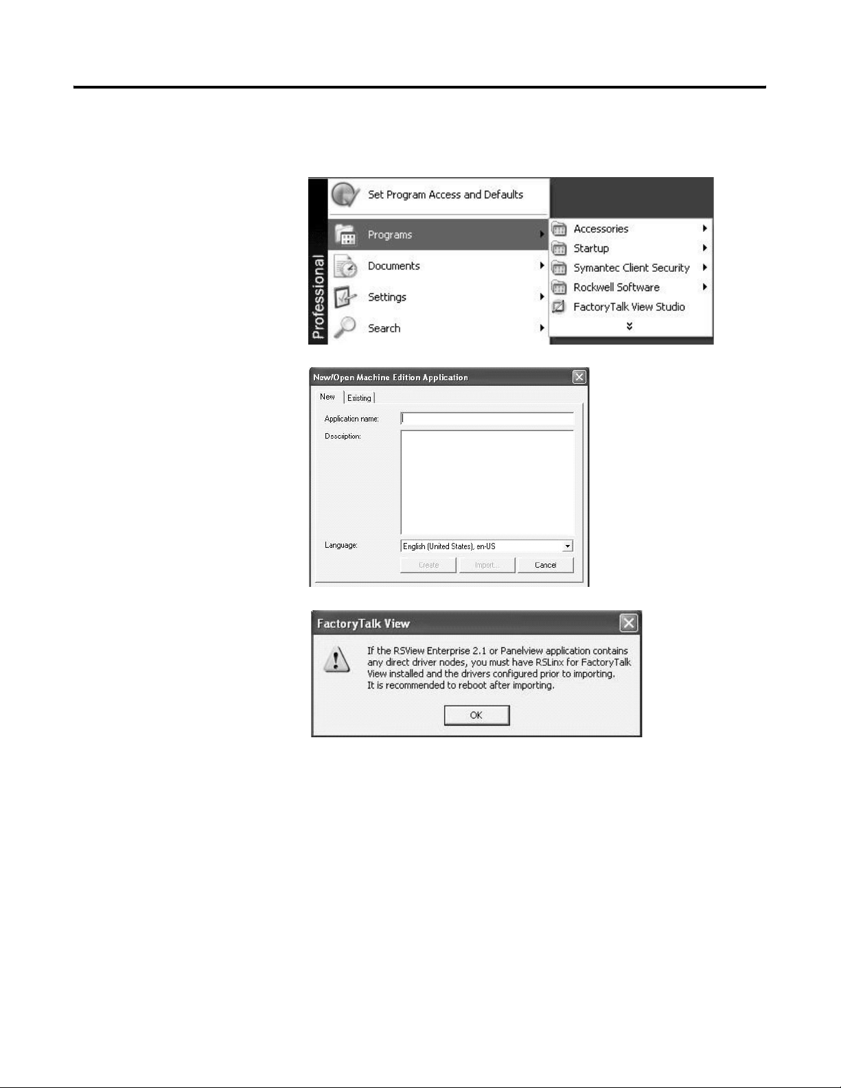
1. Launch FactoryTalk View
Studio software.
2. Click the New tab.
3. Enter an Application name
and click Import.
Follow the steps in this procedure to migrate any PanelView 1000e or
1400e application into FactoryTalk View Machine Edition software.
4. Read the FactoryTalk View
dialogue and click OK.
RSLinx for FactoryTalk does
not need to be installed
prior to importing your
PanelBuilder 1400e
application.
Publication 2711P-QS001A-EN-P - October 2007 21
Page 22
Chapter 3 Migrate Your Application
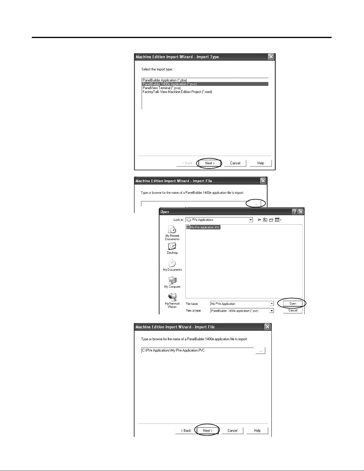
5. Select PanelBuilder 1400e
Application (*.pvc) and click
Next.
6. Click the ... button.
7. Browse to and select your
PanelBuilder 1400e .pvc
application and click Open.
8. Click Next.
22 Publication 2711P-QS001A-EN-P - October 2007
Page 23
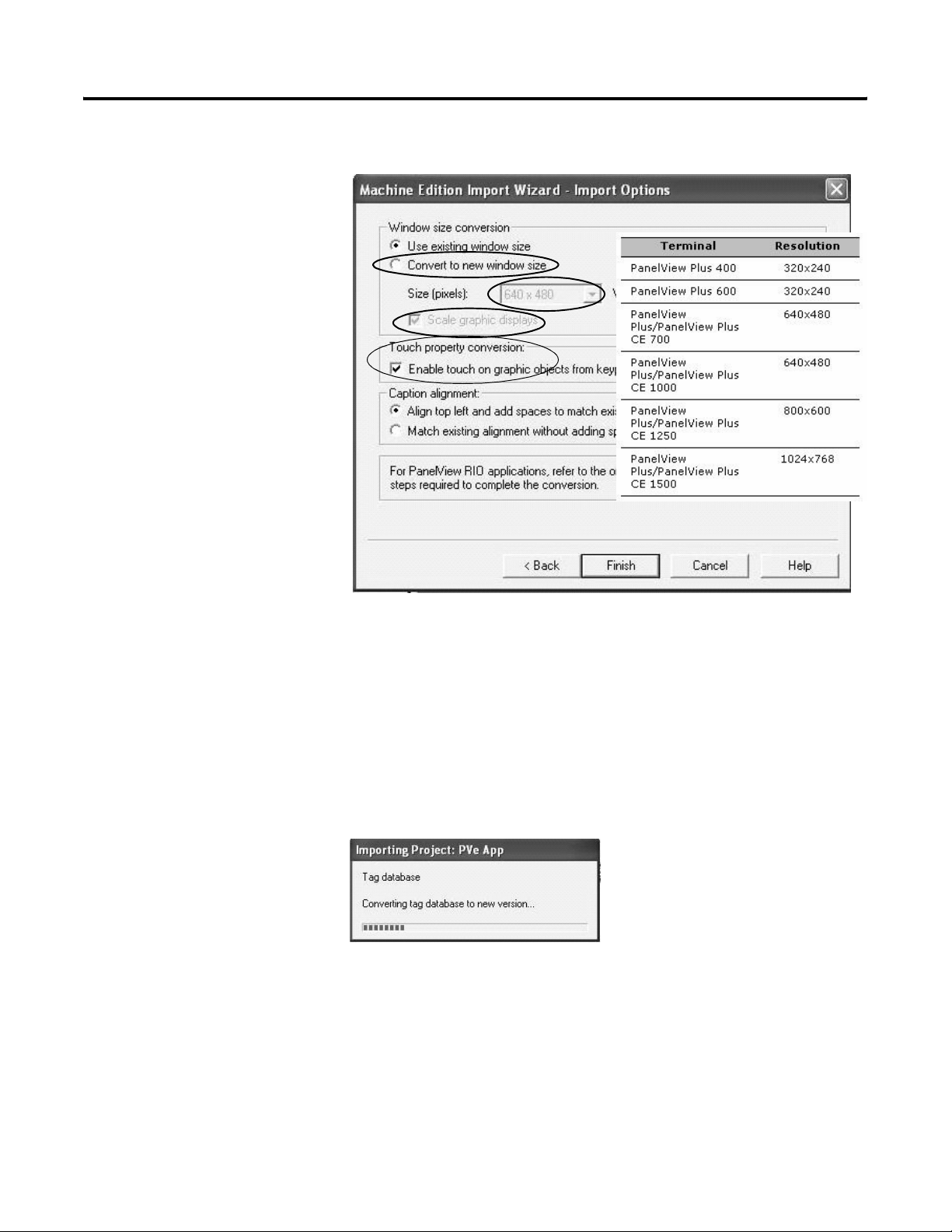
9. Configure the import
options based on your
replacement terminal.
Click Help at any time for
clarification of each dialog
option.
a. Check the Convert to
new window size
checkbox.
b. Select the size (in pixels)
of your PanelView Plus
terminal display as
shown in chart.
c. Check the Scale graphic
displays checkbox.
When selected, this
setting rescales all
displays.
d. If your original
PanelView e terminal
used a touch screen or
touch/keypad, check the
box under Touch
property conversion.
e. Click the Help button and
read the differences
between the caption
alignment options and
select an option for your
new application.
f. Click Finish.
Migrate Your Application Chapter 3
The Importing Progress
dialog shows the conversion
status. This process may
take a while, depending on
the size of your application.
When completed, you will
see the Project Status dialog
in the next step.
Publication 2711P-QS001A-EN-P - October 2007 23
Page 24

Chapter 3 Migrate Your Application
10. Review the Project Status
dialog and click OK.
11. Repeat steps 1 through 10
for each PanelBuilder 1400e
application you want to
migrate to FactoryTalk View
ME software.
24 Publication 2711P-QS001A-EN-P - October 2007
Page 25

Chapter
Review the Application Conversion Log
4
Introduction
Before You Begin
What You Need
In this chapter, you will review the conversion log generated by
FactoryTalk View Machine Edition (ME) software. The results of this
log will help you to determine what updates are required in your
converted application.
• Review migration considerations (Chapter 1).
• Select a PanelView Plus terminal replacement and adapter plate,
if required (Chapter 2).
• Install the PanelView Plus terminal in the existing PanelView
1000e or 1400e panel cutout (Chapter 2).
• Import your PanelBuilder 1400e .pvc application into
FactoryTalk View ME software (Chapter 3).
• A PanelBuilder 1400e application migrated into FactoryTalk
View ME software. This was done in Chapter 3.
• The new name given the migrated application in FactoryTalk
View ME software. This was done in Chapter 3.
• Conversion log generated by the FactoryTalk View ME import
wizard.
25Publication 2711P-QS001A-EN-P - October 2007 25
Page 26
Chapter 4 Review the Application Conversion Log
Follow These Steps
Follow this path to review changes that are required to your
FactoryTalk View ME application.
About the Conversion
Log
page 26
Open the Conversion
Log
page 27
Review the Conversion
Log
page 28
About the Conversion Log
The application conversion log is generated by the Import Wizard
when you import your PanelBuilder 1400e application into
FactoryTalk View ME software. This log provides detailed information
about objects or features that did not convert directly from your
PanelBuilder 1400e application. Use this log as a guide to update your
application accordingly. Modifications to the application are required
to verify that the application will operate correctly in FactoryTalk View
ME software.
IMPORTANT
It is important that you review each object and feature in the
converted application to verify that each will function as
expected. Because objects or features may not map directly
into FactoryTalk View ME software, you may need to update
your ladder logic to achieve the same operational results as
your PanelBuilder 1400e application.
26 Publication 2711P-QS001A-EN-P - October 2007
Page 27
Review the Application Conversion Log Chapter 4
Open the Conversion Log
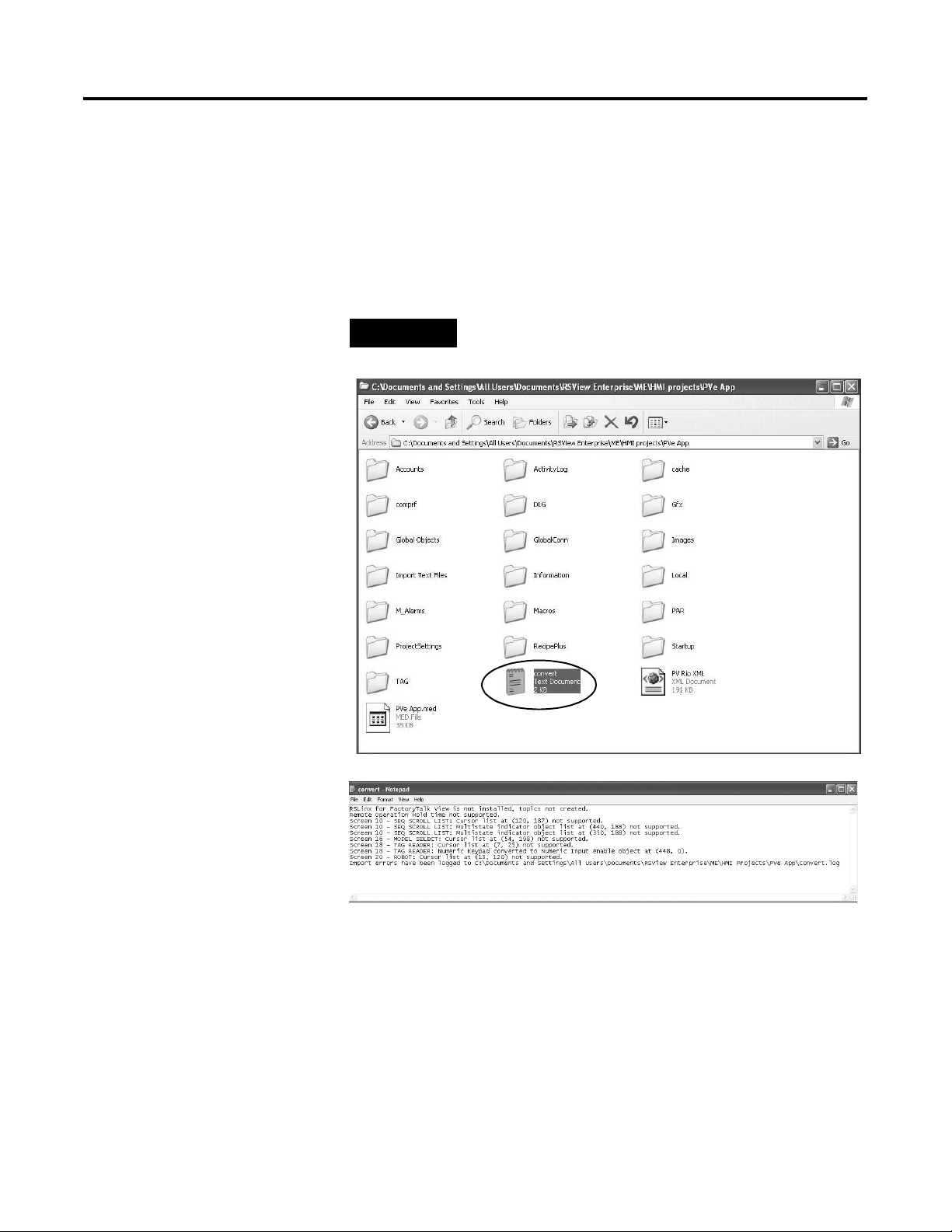
1. Navigate to this folder
location.
2. Double-click the HMI
project folder that contains
the new application name
you created.
You entered this name in
the import wizard when
importing your PanelBuilder
1400e application into
FactoryTalk View ME
software.
The conversion log is stored with the new application that you
created when importing your PanelBuilder 1400e application into
FactoryTalk View ME software.
Follow these steps to locate the conversion log.
C:\Documents and Settings\All Users\Documents\RSView
Enterprise\ME\HMI projects\
TIP
All of your FactoryTalk View ME applications will be located in
this folder. This includes new or imported applications.
3. Double-click the convert.log
file generated by the import
wizard when you imported
your application.
Your convert.log file will
vary from the example
shown.
Publication 2711P-QS001A-EN-P - October 2007 27
Page 28

Chapter 4 Review the Application Conversion Log
Review the Conversion Log
The conversion log contains a list of messages from warnings, errors,
and unsupported features or objects in the converted application. You
can compare these messages to those in the table below for
information on why the message was logged.
Most conversion log messages identify these attributes for a
FactoryTalk View ME object:
• Display name
• Position (x,y) of the object
• New graphic object name
You can use this information to locate the object and make required
modifications. The description for a message may reference a
workaround in this document.
IMPORTANT
Some features or objects are no longer supported in FactoryTalk
View ME software. However, new features or objects are
available providing the same or enhanced functionality.
Match the messages in the conversion log with the messages in the
table. The Display Name, Object Name, and Position Text references
in the messages are unique for each application.
Conversion Log Messages
Message Applies to this
PanelBuilder 1400e object
Blinking wallpaper objects not
supported.
<Object Name> at <Position> on
<Display Name>.
Screen Select Keypad converted to a
default Display List Selector.
<Object Name> at <Position> on
<Display Name>.
Screen Keypad Enable converted to a
default Display List Selector.
<Object Name> at <Position> on
<Display Name>.
• Image
• Te xt
• Drawing
Screen Select Keypad A PanelBuilder 1400e display contained a Screen Select
Screen Select Keypad A PanelBuilder 1400e display contained a Screen Keypad
Description
A PanelBuilder 1400e object with blink set to true was
converted to wallpaper.
• At runtime, the PanelView ‘e’ object would blink.
• In FactoryTalk View ME software, the object will not blink
at runtime because wallpaper objects are disabled.
Keypad object.
FactoryTalk View ME software does not support a Screen
Select Keypad object so converts it to a default Display List
Selector, which needs to be configured.
Enable object.
FactoryTalk View ME software does not support a Screen
Keypad Enable object so converts it to a default Display List
Selector, which needs to be configured.
28 Publication 2711P-QS001A-EN-P - October 2007
Page 29

Conversion Log Messages
Review the Application Conversion Log Chapter 4
Message Applies to this
PanelBuilder 1400e object
"Fixed Position" decimal point display
option not supported.
• Numeric Input Cursor Point
• Numeric Data Display
<Object Name> at <Position> on
<Display Name>.
"PLC Controlled" decimal point
display option not supported.
• Numeric Input Cursor Point
• Numeric Data Display
<Object Name> at <Position> on
<Display Name>.
"Fixed Position" decimal point input
option not supported.
<Object Name> at <Position> on
<Display Name>.
• Numeric Input Cursor Point
• Numeric Keypad Enable
• Numeric Keypad object
Description
The object has its Decimal Point Display option set to Fixed
Position.
FactoryTalk View ME software does not support an option to
display a decimal point in a numeric value. You can achieve the
same result using an expression.
For information on a workaround, refer to page 82.
The object has its Decimal Point Display option set to PLC
Controlled.
FactoryTalk View ME software does not support an option to
display a decimal point in a numeric value. You can achieve the
same result using an expression.
For information on a workaround, refer to page 81.
The object has its Decimal Point Input option set to Fixed
Position.
FactoryTalk View ME software does not support an option to
input a decimal point in a numeric value. You can achieve the
same result using an expression.
"PLC Controlled" decimal point input
option not supported.
<Object Name> at <Position> on
<Display Name>.
"Decimal Key Controlled" decimal
point input option not supported.
<Object Name> at <Position> on
<Display Name>.
Numeric Keypad converted to a
Numeric Input Enable.
<Object Name> at <Position> on
<Display Name>.
For information on a workaround, refer to page 82.
• Numeric Input Cursor Point
• Numeric Keypad Enable
• Numeric Keypad
The object has its Decimal Point Input option set to PLC
Controlled.
FactoryTalk View ME software does not support an option to
input a decimal point in a numeric value. You can achieve the
same result using an expression.
For information on a workaround, refer to page 81.
• Numeric Input Cursor Point
• Numeric Keypad Enable
• Numeric Keypad
The object has its Decimal Point Input option set to Decimal
Key Controlled.
FactoryTalk View ME software does not support an option to
input a decimal point in a numeric value. You can achieve the
same result using an expression.
For information on a workaround, refer to page 81.
Numeric Keypad The display contains a Numeric Keypad object.
FactoryTalk View ME software does not support a Numeric
Keypad object so converts it to a Numeric Input Enable, which
needs to be configured.
Publication 2711P-QS001A-EN-P - October 2007 29
Page 30

Chapter 4 Review the Application Conversion Log
Conversion Log Messages
Message Applies to this
PanelBuilder 1400e object
Date labels not supported on Trend's
Trend A trend has one or more of its minimum, median or maximum
X-Axis.
<Object Name> at <Position> on
<Display Name>.
Blinking pens not supported by Trend.
Trend A trend had one or more of its pens configured to blink.
<Object Name> at <Position> on
<Display Name>.
Background screen plotting of pens
Trend A trend has one of its pens configured to use background
using expressions not supported by
Trend.
<Object Name> at <Position> on
<Display Name>.
Cursor List object at
Cursor List A display contains a Cursor List object.
<PV ‘e’ Position> on <Display Name>
not supported.
Description
date labels enabled.
The FactoryTalk View ME trend displays the current date in its
title. It does not display the minimum, median or maximum
date as part of its X-axis.
The FactoryTalk View ME trend does not allow any of its pens
to blink.
screen plotting and has an expression assigned to the Pen
Value control.
The FactoryTalk View ME trend supports background screen
plotting by adding the tags assigned to the Pen1 to Pen8
controls to a Data Log Model.
You cannot add expressions to a Data Log Model.
FactoryTalk View ME software does not support a Cursor List
object so does not convert it. See page 68 for a workaround.
Multistate Indicator Object List at
<PV ‘e’ Position> on <Display Name >
not supported.
Local Message Object List at
<PV ‘e’ Position> on <Display Name >
not supported.
Numeric Data Display Object List at
<PV ’e’ Position> on <Display Name >
not supported.
Multi-Line Alarm Window blinking
not supported by [ALARM] display.
Multistate Indicator Object List A display contains a Multistate Indicator Object List.
FactoryTalk View ME software does not support a Multistate
Indicator Object List so does not convert it. See page 56 for a
workaround.
Local Message Object List. A display contained a Local Message Object List.
FactoryTalk View ME software does not support a Local
Message Object List so does not convert it. See page 60 for a
workaround.
Numeric Data Display Object
A display contains a Numeric Data Display Object List.
List
FactoryTalk View ME software does not support a Numeric
Data Display Object List so does not convert it. See page 64 for
a workaround.
Alarm Configuration The Alarm Message Window is enabled with:
• Multi-line set.
• Blink enabled.
The multiline Alarm Window is converted to a FactoryTalk
View ME software [ALARM] display containing an Alarm List
object.
30 Publication 2711P-QS001A-EN-P - October 2007
Page 31

Conversion Log Messages
Review the Application Conversion Log Chapter 4
Message Applies to this
PanelBuilder 1400e object
"PLC Controlled Audio" alarm control
Alarm Configuration The PLC Controlled Audio control has a tag assigned.
not supported.
"PLC Controlled Relay" alarm control
Alarm Configuration The PLC Controlled Relay control has a tag assigned.
not supported.
Alarm message "Relay" option not
Alarm Message Configuration One or more relay flags has been enabled for alarm messages.
supported.
Only one hold time is used for
Alarm Configuration One or more of these controls has a tag assigned:
alarming. "Remote Alarm Operation
Hold Time" not supported.
Description
FactoryTalk View ME software does not support a PLC
Controlled Audio alarm control so does not convert it.
FactoryTalk View ME software does not support a PLC
Controlled Relay alarm control so does not convert it.
FactoryTalk View ME software does not support the triggering
of a relay when an alarm is triggered so will not convert this
feature.
• Silence Alarms to PLC
• Clear Window to PLC
• QTY/TIME Reset to PLC
• Message to PLC
FactoryTalk View ME software supports only one hold time for
alarming and this will be set to the value of the PanelView ’e’
Remote Alarm Ack Control Hold Time. The value of the
PanelView ’e’ Remote Alarm Operation Hold Time does not
convert.
"Remote Alarm Control Delay Time"
not supported.
Bit Acknowledging of alarms not
supported.
Screen security settings not
converted for <Display Name>.
RSLinx for FactoryTalk View is not
installed, topics not created.
<PanelView ’e’ Tag Name> converted
to memory tag, as its address is
blank.
Alarm Configuration These controls have a tag assigned:
• Acknowledge to PLC
• Acknowledge Control
• Message to PLC
In FactoryTalk View ME software, if the Ack control is assigned
to an alarm trigger, the terminal will immediately set the Ack
control without waiting for a delay time when the alarm is
acknowledged. The Remote Alarm Control Delay Time does not
convert.
Alarm Configuration The Alarm Acknowledge to PLC option is set to Bit and the
Acknowledge to PLC control has one or more tags assigned.
FactoryTalk View ME software does not support bit
acknowledging of alarms so does not convert the
Acknowledge to PLC tags.
Secure Screen Configuration A screen has one or more Authorize Operator settings enabled.
Screen security is not converted.
FactoryTalk View ME software does support display security.
Security is configured differently.
Communication You need to recreate the shortcut name to the PLC in RSLinx
Enterprise software under Communication Setup.
Any PanelView ’e’ Remote I/O tag with a blank address is
converted to an HMI memory tag.
Publication 2711P-QS001A-EN-P - October 2007 31
Page 32

Chapter 4 Review the Application Conversion Log
Conversion Log Messages
Message Applies to this
PanelBuilder 1400e object
<PanelView ’e’ Tag Name> converted
to memory tag, as its data type is not
supported.
<PanelView ’e’ Tag Name> converted
to memory tag, as the "Bit Position"
data type is not supported.
<PanelView ’e’ Tag Name> converted
to memory tag, as its addresses
references an undefined rack.
<PanelView ’e’ Tag Name> converted
to memory tag, as its addresses is
invalid.
Description
Any PanelView ’e’ Remote I/O tags with these data types are
converted to HMI memory tags.
• 1 Digit BCD
• 2 Digit BCD
• 3 Digit BCD
• 5 Digit BCD
• 6 Digit BCD
• 7 Digit BCD
If the data type of a PanelView ’e’ Remote I/O tag is bit
position but the address does not reference a single bit, the
tag is converted to an HMI memory tag.
If a PanelView ’e’ Remote I/O tag has an address with an
undefined rack, the tag is converted to an HMI memory tag.
If a PanelView ’e’ Remote I/O tag does not have a valid I/O
address or block transfer address, the tag is converted to an
HMI memory tag.
32 Publication 2711P-QS001A-EN-P - October 2007
Page 33

Review Object Mapping
Chapter
5
Introduction
Before You Begin
What You Need
In this chapter, you will review how objects and expressions from
PanelBuilder 1400 software map to FactoryTalk View Machine Edition
(ME) software.
• Review migration considerations (Chapter 1).
• Select a PanelView Plus terminal replacement and adapter plate,
if required (Chapter 2).
• Optionally install the PanelView Plus terminal in the existing
PanelView 1000e or 1400e panel cutout (Chapter 2).
• Import your PanelBuilder 1400e .pvc application into
FactoryTalk View ME software (Chapter 3).
• Review the conversion log for your migrated application
(Chapter 4).
• A PanelBuilder 1400e application migrated into FactoryTalk ME
software.
• Conversion log generated by the FactoryTalk View ME Import
Wizard.
33Publication 2711P-QS001A-EN-P - October 2007 33
Page 34

Chapter 5 Review Object Mapping
Follow These Steps
Follow these steps to review how PanelBuilder 1400e objects and
expressions map to FactoryTalk View ME software. This information
will help you correct application errors listed in the conversion log.
Reviewing Object
Mapping
page 35
Reviewing and
Modifying Expressions
page 37
34 Publication 2711P-QS001A-EN-P - October 2007
Page 35

Review Object Mapping Chapter 5
Reviewing Object Mapping
This table identifies PanelBuilder 1400e graphic objects that migrate
into a FactoryTalk View ME application.
IMPORTANT
It is important that you verify the function of all objects after
importing your application to FactoryTalk View ME software.
New objects may not function as expected.
Mapping Objects Between PanelBuilder 1400e and FactoryTalk View ME Software
This PanelBuilder 1400e object Maps to this FactoryTalk View ME object Explanation
Increment Value Button Ramp Button
Decrement Value Button Ramp Button
Increment Value Button with Display Ramp Button and Numeric Display
Decrement Value Button with Display Ramp Button and Numeric Display
Small and Large ASCII Input String Input Enable
Arc with Fill Style set to Solid ME Arc and ME Line The PanelBuilder 1400e object is a closed
shape; the View ME object is not closed
between the arc of two points.
Screen List Selector Screen List Selector
Screen List Selector Enter Button Enter List Key
Screen List Selector
Down Cursor Button
Screen List Selector
Up Cursor Button
Control List Selector Control List Selector
Control List Selector Enter Button Enter List Key
Control List Selector
Down Cursor Button
Control List Selector
Up Cursor Button
Small and Large Screen
Select Keypad
Screen Keypad Enable Display List Selector You will need to configure this object to
Goto Screen Button Goto Display Button
Return to Previous Screen Button Return to Display Button
ASCII Display String Display
Numeric Keypad Enable Button Numeric Input Enable Button
Normally Open
Momentary Push Button
Move Down List Key
Move Up List Key
Move Down List Key
Move Up List Key
Display List Selector You will need to configure this object to
change to the appropriate displays.
change to the appropriate displays.
Momentary Push Button
Normally Closed
Momentary Push Button
Publication 2711P-QS001A-EN-P - October 2007 35
Momentary Push Button
Page 36

Chapter 5 Review Object Mapping
Mapping Objects Between PanelBuilder 1400e and FactoryTalk View ME Software
This PanelBuilder 1400e object Maps to this FactoryTalk View ME object Explanation
Multistate Indicators Multistate Indicators
Numeric Display Numeric Display
Screen Print Button Screen Print Button
Time Display Time and Date Display Set to show time only.
Date Display Time and Date Display Set to show date only.
Alarm History
Sort Alarms Button
Sort By Time/Sort By Value
Alarm Status Reset Qty/Time Button Reset Alarm Status Button
Alarm Panel Alarm Banner
Single Line Alarm Window Alarm Banner
Alarm Status Screen Alarm Status List
Local Messages Local Messages
Information Messages Information Messages
Bar Graphs Bar Graphs
Trend Trend
Text Text
Drawing Objects Drawing Objects
ISA Symbols ISA Symbols
Bitmaps, DXF Images Bitmaps, DXF Images
Digital and String Tag Types Bit and String Tag Types
Supported Analog Tag Types:
• Unsigned Integer
• Integer
• Long Integer
• Floating Point
• Byte
• 3-BCD, 4-BCD, 8-BCD
Supported Analog Tag Types:
• Unsigned Integer
• Integer
• Long Integer
• Floating Point
• Byte
• 3-BCD, 4-BCD
Supported communication:
• DH Plus
• Remote I/O multirack
• ControlNet
File transfers occur over DH+ or
ControlNet networks.
Supported communications:
• DH Plus
• Remote I/O multirack
• ControlNet
File transfers occur over DH+ or ControlNet
networks. No bridging network protocols.
File transfers use a memory card. File transfers use a CompactFlash card.
36 Publication 2711P-QS001A-EN-P - October 2007
Page 37

Review Object Mapping Chapter 5
Reviewing and Modifying Expressions
If any objects in your PanelView 1000e or 1400e application contain
expressions, you need to review the order of precedence in each
expression. The order of precedence may be different between
PanelBuilder 1400e software and FactoryTalk View ME software.
The table compares the order of precedence in expressions between
PanelBuilder 1400e and FactoryTalk View ME software.
IMPORTANT
The text "--check and reuse as needed--" precedes all migrated
expressions. Remove this text from each expression and verify
the order of precedence.
The conversion log does not indicate which objects contained
expressions with the “--check and reuse as needed--”” text. Refer to
Appendix A. Tag substitution provides a method of identifying if a
display contains expressions that require updates. The object explorer
section also describes how to highlight objects with expressions on
the display.
Expressions: Order of Precedence
PanelBuilder 1400e Software FactoryTalk View ME Software
( ) ( )
- (negation) NOT, ~ (tilde)
*, / (floating point division) *, /, MOD, %, **, AND, &&, &, >>, <<
\ (integer point division) +, -, OR, ||, | ^
MOD EQ, = =, NE, <>, LT, <, GT, >, LE, <=. GE. =>
+, - (subtraction) Unchanged
+, < >, < >, <=, >+ Unchanged
NOT Unchanged
And Unchanged
Or Unchanged
Xor Unchanged
Publication 2711P-QS001A-EN-P - October 2007 37
Page 38

Chapter 5 Review Object Mapping
38 Publication 2711P-QS001A-EN-P - October 2007
Page 39

Chapter
6
Review Unsupported Features and Implement
Workarounds for Migration Issues
Introduction
Before You Begin
What You Need
In this chapter, you will review unsupported features in FactoryTalk
View Machine Edition (ME) software and workarounds for common
migration issues. This will help you to resolve errors in the migrated
application.
• Review migration considerations (Chapter 1).
• Select a PanelView Plus terminal replacement and adapter plate,
if required (Chapter 2).
• Optionally install the PanelView Plus terminal in the existing
PanelView 1000e or 1400e panel cutout (Chapter 2).
• Import your PanelBuilder 1400e .pvc application into
FactoryTalk View ME software (Chapter 3).
• Review the conversion log for your migrated application
(Chapter 4).
• Review object and expression mapping (Chapter 5).
• A migrated PanelBuilder 1400 application into FactoryTalk ME
software.
• Conversion log generated by the FactoryTalk View ME Import
Wizard.
39Publication 2711P-QS001A-EN-P - October 2007 39
Page 40

Chapter 6 Review Unsupported Features and Implement Workarounds for Migration Issues
Follow These Steps
Follow this path to review unsupported features in FactoryTalk View
ME software and workarounds for common migration issues.
Reviewing Unsupported
Features
page 41
Reviewing Common
Migration Issues and
Workarounds
page 46
Replacing Scrolling List
Objects
page 47
Replacing the Cursor List
page 48
Bit Position Data Type
Workaround
page 80
Replacing the Multistate
Indicator Object List
Replacing the Local
Message Object List
Replacing the Numeric
Data Display Object List
Replacing the Set Bit
Cursor Point Object
page 56
page 60
page 64
page 68
PLC Controlled Decimal
Point Workaround
page 81
Fixed Position Decimal
Point Workaround
page 82
Retain Last State
Workaround
page 83
Ladder Logic Updates to
Support Visible States
page 86
40 Publication 2711P-QS001A-EN-P - October 2007
Page 41

Review Unsupported Features and Implement Workarounds for Migration Issues Chapter 6
Reviewing Unsupported
Some PanelBuilder 1400e objects or features are not supported in
FactoryTalk View Machine Edition software. Compare the conversion
Features
log with the information on unsupported features to assist with
updates to your migrated application. Additional information is
provided where it is possible to achieve the same result using another
option or work around in your migrated application.
Unsupported Objects or Features in FactoryTalk View Machine Edition
For this PanelBuilder 1400e object These features are unsupported
in FactoryTalk View ME software
Trend Blinking Pens
Date Labels on X-Axis Date is displayed in the trend title.
Background Screen Plotting You can plot tag values in the background by
Scrolling List Objects
• Cursor List
• Multistate Indicator Object List
• Local Message Object List
• Numeric Data Display Object List
Blank States For information on replacement objects in
Additional Information
assigning the tags to a data log model. Tags
configured for background screen plotting are
automatically assigned to a data log model on
conversion. However, data log models do not plot
expression values. Expressions configured for
background screen plotting are not converted.
FactoryTalk View ME software, refer to page 47.
Set Bit Cursor Point Object Not Supported For information on replacement objects , refer to ID:
44265 in the Knowledgebase and also to page 68.
Numeric Display Polarity If a PanelBuilder 1400e application was configured
with the polarity control requiring a negative number
to display the minus sign, the numeric display will
not work properly after the application is converted.
Implicit The implicit option in a PanelBuilder 1400e
application is converted to a fixed position in the
new object. Review these objects to verify that the
number of digits and decimal places are adequate
for displaying the correct value.
Numeric Input Cursor Point Fixed Position Decimal Fixed Position Decimal will convert correctly. You
need to remove the comments from the expressions.
PLC Controlled Decimal Display PLC Controlled Decimal Display may or may not
convert correctly. For information on a workaround in
FactoryTalk View ME software, refer to page 81.
Retain Cursor on Cancel
Goto Configure Mode Button Object not converted
Publication 2711P-QS001A-EN-P - October 2007 41
Page 42

Chapter 6 Review Unsupported Features and Implement Workarounds for Migration Issues
Unsupported Objects or Features in FactoryTalk View Machine Edition
For this PanelBuilder 1400e object These features are unsupported
Additional Information
in FactoryTalk View ME software
Wallpaper, Image, Text, Arc, Ellipse, Line,
Panel, Rectangle, Wedge
Blink Property If you want an object to blink at runtime, unlock the
wallpaper. In FactoryTalk View ME software, all of
the list objects except images and panels use color
animation to blink.
• Panels use the blink property to blink.
• Color images do not blink.
• Monochrome images use the blink property to
blink.
All Objects Object Names Object names are replaced with default object
names in FactoryTalk View ME software. The
PanelBuilder 1400e object name is used for the
object's description. You can view and edit the name
and description in the property panel.
Caption and Image Placement FactoryTalk View ME software supports one, three,
or nine positions for captions and images, depending
on the type of object. On conversion, captions and
images are positioned using the closest match.
Some captions might:
• overlap images.
• be truncated.
• be clipped to fit the object.
Realign or resize objects for best fit.
Multiple Image Labels FactoryTalk View ME software supports one image
label per object or state. If a PanelBuilder 1400e
object is configured to use multiple image labels,
only the top left image is converted. Create a single
image from multiple ones.
Text Overlap Change the border width or resize objects.
Expressions Expressions are converted without modification and
then commented.
• Warning text is placed at the beginning of the
first line of the expression.
• Exclamation marks (!) are placed at the beginning
of each subsequent line of the expression.
To enable the expression, you must remove the
warning text and exclamation marks, and revise the
syntax if necessary.
Expression Length The maximum length of expressions in FactoryTalk
View ME software is 1024 characters. If a
PanelBuilder 1400e expression contains more than
1024 characters, the excess characters are not
converted. Modify the expressions as needed.
42 Publication 2711P-QS001A-EN-P - October 2007
Page 43

Review Unsupported Features and Implement Workarounds for Migration Issues Chapter 6
Unsupported Objects or Features in FactoryTalk View Machine Edition
For this PanelBuilder 1400e object These features are unsupported
Additional Information
in FactoryTalk View ME software
All Displays Display Names In FactoryTalk View ME software, unsupported
characters in display names are replaced with the
underscore character.
Graphic Alignment The graphics may not line up and appear properly.
Resize graphics as needed.
Remote Alarm Ack Bit Array Data Types Workaround with ladder logic change by using the
ack value to indirectly change a tag in an array.
Alarming Controls Acknowledge To PLC Control
Remote Alarm Control Delay Time When an alarm is acknowledged in the FactoryTalk
View ME application, the Ack control, if assigned, is
set immediately, without waiting for a delay time.
Update the ladder logic to implement a delay timer
in PLC.
PLC Controlled Relay Control The terminal does not have a relay. Use the PLC
controller to turn on device.
PLC Controlled Audio Control The terminal does not have audio. Use the PLC
controller to turn on a horn.
Blinking Alarm Messages
Alarm Relays The terminal does not have a relay. Use the PLC
controller to turn on device.
Remote Alarm Operation Hold Time The PanelBuilder 1400e Remote Alarm Ack Control
Hold Time will be used for all alarm hold times. You
can change the hold time in the Advanced tab of the
Alarm Setup editor in FactoryTalk View ME software.
Alarm Handshaking
Message Handshake Control
Security Runtime Password Changes In the PanelBuilder 1400e software, user passwords
are set up in the configuration mode screens.
FactoryTalk View ME software requires the Change
Password button on a display.
Display Security Settings FactoryTalk View ME software uses a different
method to assign security to graphic displays. You
must reapply security. The software uses a logon
system of security similar to RSView32 software.
Once logged on, the operator does not need to
re-enter the password until manually logged off, or
optionally after an idle time.
Publication 2711P-QS001A-EN-P - October 2007 43
Page 44

Chapter 6 Review Unsupported Features and Implement Workarounds for Migration Issues
Unsupported Objects or Features in FactoryTalk View Machine Edition
For this PanelBuilder 1400e object These features are unsupported
Additional Information
in FactoryTalk View ME software
Communications (RIO) Passthrough Downloads Use an Ethernet connection or a CompactFlash card
to transfer files.
Remote I/O Connector Wiring The Remote I/O connector wiring for the PanelView
Plus terminal is reversed from the PanelView 1000e
and 1400e terminals.
Remote I/O Tag with Blank Address Remote I/O tags with blank addresses are converted
to HMI memory tags. An error is recorded in the
conversion log.
Data Types Bit Position If a bit position data type does not reference a single
bit, it is converted to an HMI memory tag. An error is
recorded in the conversion log.
• Create an expression to isolate the bits used to
drive the state of the display object, such as a
multistate indicator.
For information on how to implement this
workaround, refer to page 80.
• For write objects, such as push buttons, there is
no workaround except to change the ladder logic.
• For Remote I/O, you may need to change the
Rack/Block Transfer configuration.
• For DH+ and ControlNet, unscheduled tags with
the bit position data type are converted to HMI
analog tags with a data type of default.
Binary A binary tag is converted to an HMI memory tag if it
does not reference:
• a single bit.
• a single word.
• a length or range of 8 or 16 bits and does not
start at an offset of 0 or 8 (SLC controller) or 10
(PLC-5 controller).
An error is recorded in the conversion log.
• Create an expression to isolate the bits used to
drive the state of display object, such as a
multistate indicator.
• For write objects such as push buttons, there is
no workaround.
BCD BCD data types are not supported: 1-BCD, 2-BCD,
5-BCD, 6-BCD, 7-BCD, 8-BCD.
Tags that use this data type are converted to analog
tags with the default data type. The default data
type uses floating point values.
Byte If the byte address does not have a bit offset of 0 or
8, it is converted to an HMI memory tag. The error is
recorded in the conversion log
44 Publication 2711P-QS001A-EN-P - October 2007
Page 45

Review Unsupported Features and Implement Workarounds for Migration Issues Chapter 6
Unsupported Objects or Features in FactoryTalk View Machine Edition
For this PanelBuilder 1400e object These features are unsupported
Additional Information
in FactoryTalk View ME software
Data Types Block Tags Block tags monitor alarms in PanelBuilder 1400e
applications and are converted to bit arrays. An error
is recorded in the conversion log.
Analog Tags with One Bit Length PanelBuilder 1400e analog tags that are one bit in
length (0 is min, 1 is max) convert to analog tags in
FactoryTalk View ME software, but the value is
0 and -1 (all bits off, all bits on). This feature is
typically used for indicator objects with two states.
In a FactoryTalk View application, this results in an
incorrect state. Change analog tags to bit data types.
Important: No message appears in the conversion
log. Modify any analog tags that are one bit in
length.
File Transfers Transfer Inhibit These three controls are not necessary in FactoryTalk
View ME software because the transfer utility lets
you transfer the runtime project file while running a
project on the runtime terminal.
Transfer Request
Transfer Status
Design Time Features Tag Cross-Reference
Screen Captures
Application Validation
Application memory usage
calculation
Saving applications to a user
specified location
Tag Search and Replace Use tag substitution on each page or see
Default Object/Graphic Display
Settings
Power Up Options Write Last Terminal State to
Controller
Knowledgebase ID: 29942. RSView Graphic Tags
Search and Replace using Graphics XML Exported
Files
Publication 2711P-QS001A-EN-P - October 2007 45
Page 46

Chapter 6 Review Unsupported Features and Implement Workarounds for Migration Issues
Reviewing Common Migration Issues and Workarounds
Required Files and Utilities
Some graphic objects, data types, and other features do not migrate
directly into FactoryTalk View ME software. The most common
migration issues relate to these objects or features:
• Scrolling list objects
• Cursor list objects
• Set bit cursor point objects
• Bit position data type
• PLC controlled or fixed position decimal
• Retain last state
• Ladder logic updates to support visible states
FactoryTalkView ME software provides replacement objects and
workarounds that provide the same if not similar functionality.
The Rockwell Automation Knowledgebase document contains files
and utilities to simplify the migration process.
Document ID: 44265
Document Title: Migrating PanelView Enhanced Terminal Applications
Download the Migration Solutions.zip attachment containing the
required files and utilities. This file contains a Migration Solutions.apa
demo project, the tag converter wizard utility, and a set bit cursor
point ActiveX Control.
• Migration solutions demo project contains replacement
objects for the cursor list, local message list, multisate indicator
object list, numeric data display object list and the set bit cursor
point. You can import these displays into your converted
application, copy the objects, and then configure them.
To see how the set bit cusror point works, click the Display Test
Run button on the set bit cursor point display.
• Tag converter wizard utility optimizes tags in the converted
application. To improve performance, the utility converts HMI
tags to alias or direct reference tags.
• Set bit cursor point ActiveX control replaces the set bit
cursor point object in the converted application. To activate this
control, it needs to be registered on our computer and the
PanelView Plus CE terminal
46 Publication 2711P-QS001A-EN-P - October 2007
Page 47

Review Unsupported Features and Implement Workarounds for Migration Issues Chapter 6
Replacing Scrolling List
Scrolling list objects in PanelBuilder 1400e software consists of a
cursor list and one or more object lists. The operator can move
Objects
through a maximum of 999 items within these object lists.
Scrolling lists can multiplex PLC output data to the PanelView ‘e’
terminal, minimizing the ladder logic required to display and edit
large amounts of data.
FactoryTalk View ME software does not support scrolling list objects.
but does provide replacement objects to perform the same operations.
Replacement Objects for Scrolling List Objects
Replace this PanelView ‘e’ object With this FactoryTalk View ME object See
Cursor List • Piloted Control List Selector
• Key buttons
• Terminal function keys
Multistate Indicator Object List Multistate Indicator Page 56
Local Message Object List Local Message Page 60
Numeric Data Display Object List Numeric Data Display Page 64
• Page 48
• Page 53
• Page 55
Publication 2711P-QS001A-EN-P - October 2007 47
Page 48

Chapter 6 Review Unsupported Features and Implement Workarounds for Migration Issues
Replacing the Cursor List
1. Select
Objects>Advanced>Piloted
Control List Selector.
2. Draw and size the object on
your display.
Replacement objects for the cursor list object in FactoryTalk View ME
software are the piloted control list selector, key objects, and terminal
function keys.
• The piloted control list selector replaces the cursor list.
• The key objects provide on-screen navigation for the list such as
up cursor, down cursor, and the enter key.
• The terminal function keys are assigned to the key objects
allowing the operator to navigate the list on keypad terminals.
Create a Piloted Control List Selector
Follow these steps to replace the cursor list object with a piloted
control list selector.
48 Publication 2711P-QS001A-EN-P - October 2007
Page 49

3. Double-click the piloted
control list selector object to
open its properties.
4. In the Border style
pull-down list, select None
so when this object is
grouped it appears as a
single object.
5. In the Number of states
pull-down list, select the
number of states to match
the original PanelBuilder
1400e cursor list object.
6. Set the Back color to match
the background properties
of the original cursor list
object.
Review Unsupported Features and Implement Workarounds for Migration Issues Chapter 6
7. Set the Selection back color
to match the foreground
properties of the original
cursor list object.
8. Under Other, verify that all
boxes are unchecked.
9. Click the States tab.
Publication 2711P-QS001A-EN-P - October 2007 49
Page 50

Chapter 6 Review Unsupported Features and Implement Workarounds for Migration Issues
10. Configure each state.
a. Select a state.
b. Enter a Value that
matches the state value of
the original cursor list.
c. Select an Access option
for the state.
The default access is
Operator and Remote.
This option provides the
same functionality as the
original cursor list.
Select None for any state
that was a skipped state
in the original cursor list.
d. Repeat a to c for each
state that was in the
original cursor list object.
Access Options Description
Operator and Remote Both the operator and the controller can select the state.
This is the default.
Operator Only an operator can select the state.
Remote The state can only be selected remotely.
None The state cannot be selected. This is equivalent to a
skipped state in the original cursor list.
When the operator scrolls to a skipped state in a
PanelBuilder 1400e application, the list skips past the
state. Because the operator cannot select the state, the
state value is never written to the object’s Cursor
Indicator to PLC connection.
When the operator scrolls to a None state in a FactoryTalk
View ME application, the cursor becomes hollow to
indicate that the state is invalid. Because the state
cannot be selected, the state value is never written to the
object’s Value connection.
50 Publication 2711P-QS001A-EN-P - October 2007
Page 51

Review Unsupported Features and Implement Workarounds for Migration Issues Chapter 6
11. Click the Connections tab.
12. Assign a tag or expression
to each connection as
needed.
The table below cross
references each connection.
13. Click OK when done.
Mapping Piloted Control List Selector Connections
PanelBuilder 1400e tag
connection maps To
Cursor Indicator to PLC Value Read and
Cursor Control
from PLC
Enable PLC to Controlled
List
This FactoryTalk View
ME connection
Indicator Read When the list is remotely controlled, this connection is used to select a state in
Remote Access Read
Connection
Ty pe
Write
Description
When a display that includes a piloted control list selector is opened and the
operator has control of the list, the application reads the Value connection to
determine what state to select. When the operator selects a valid state, the
state's value is written to the Value connection. The application does not read
the Value connection at any other time.
If the list is remotely controlled, you do not need to assign the Value
connection. The remote controller uses the Indicator connection to select a
state. If the Value connection is assigned, the value of the selected state is
written to the Value connection.
If the Write on enter checkbox is checked (on the General tab), the application
does not write to the Value connection until the operator selects a state and
presses Enter.
If the Write on enter checkbox is not checked (on the General tab), the
application writes to the Value connection as soon as a state is selected. The
Enter and Enter Handshake controls are ignored.
the list.
This connection determines whether the operator or a remote
controller selects states in the list. If you assign a tag or an expression
to this connection, the object is remotely controlled. The object is
remotely controlled if the tag or expression is assigned to a nonzero
value.
If you do not assign this connection or if the connection is assigned
and set to a value of 0, the object is controlled by the operator.
Top Position to PLC Top Position Write When the list scrolls, the value of the top visible state in the list is written to
the Top Position tag.
Publication 2711P-QS001A-EN-P - October 2007 51
Page 52

Chapter 6 Review Unsupported Features and Implement Workarounds for Migration Issues
Mapping Piloted Control List Selector Connections
PanelBuilder 1400e tag
connection maps To
Enter Key Control
Enter Handshake
(1)
(1)
This FactoryTalk View
ME connection
Visible States Write Assign an array tag to this connection. When the list scrolls, the values of the
Enter Write This connection accepts values of 0 or 1. The connection determines how long
Enter Handshake Handshake This connection resets the Enter connection using the Handshake reset type
Connection
Ty pe
Description
visible states are written to the array tag. The first visible state is written to
the first element of the array tag, the second visible state is written to the
second element of the array tag, and so on. The length of the array tag must be
equal to the number of visible states in the object.
The syntax of the array tag depends on the type of OPC data server the
application is using. If you are using RSLinx Enterprise software, you must use
this syntax.
Syntax: [shortcut]tagname,Larraylength
Example: [PLC5]N7:0,L5
Do not leave a space between the tag address and the length.
Correct: [PLC5]N7:0,L5
Incorrect: [PLC5]N7:0, L5
In PanelBuilder 1400e software, an individual tag is assigned to each visible
state. In FactoryTalk View ME software, you cannot assign an individual tag to
each visible state. If an action is required when the operator selects a visible
state, you must update the ladder logic. You must use a direct reference for
this assignment. You cannot use an HMI tag.
For details on how to implement the workaround for visible states, refer to
Ladder Logic Changes on page 86.
the Enter key press is registered. Use this connection for Enter key
handshaking.
property specified on the Timing tab. Use this connection for Enter key
handshaking if you want the Enter connection to be reset when a value at the
data source changes.
(1)
Available only when you enable the cursor list enter button.
If you assign an expression, the application calculates the value of the
expression and resets the Enter connection when the expression value meets
the conditions of the Handshake reset type option.
Retain Last State
PanelBuilder 1400e software has a Retain the Last State feature for the
cursor list object.
• When you return to a display with the cursor list object and this
feature is enabled, the last selected state is retained and
reselected.
• When you return to a display with the cursor list object and this
feature is disabled, the selected state is determined by the value
read at the Cursor Indicator to PLC connection.
The piloted control list selector in FactoryTalk View ME software does
not have an equivalent feature to Retain the Last State. The object
always reads the Value connection to determine what state to select.
For information on a workaround for this functionality, refer to page
83.
52 Publication 2711P-QS001A-EN-P - October 2007
Page 53

Review Unsupported Features and Implement Workarounds for Migration Issues Chapter 6
Resize the Piloted Control List Selector
You need to resize the piloted control list selector to make it appear
visually the same as the cursor list object.
Resize the object so that only the cursor is visible.
White Line
Cursor List Object
TIP
Cursor
Piloted Control List
Selector Object
To hide the white line next to the cursor, place a line object over
it, and assign a background color that matches the list. The
covered line will not be visible to the operator. Group the
objects so when the object is resized, the line remains hidden.
Assign Navigation Keys to Piloted Control List Selector
In PanelBuilder 1400e software, you use key objects and terminal
funtion keys to navigate through the cursor list. FactoryTalk View ME
software provides similar objects and keys to navigate through the
piloted control list selector.
Mapping Key Objects
This key object in FactoryTalk
View ME software
Move Up Up Cursor
Move Down Down Cursor
Page Up Page Up
Page Down Page Down
Home Home
End End
Enter Enter
Publication 2711P-QS001A-EN-P - October 2007 53
Replaces this cursor list button in
PanelBuilder 1400e software
Page 54

Chapter 6 Review Unsupported Features and Implement Workarounds for Migration Issues
Follow these steps to create key objects for the piloted control list
selector.
1. Open the display with
piloted control list selector.
2. Select Objects>Key> and an
option, then draw the object
on the display.
You can use all of the
objects on the key submenu
to navigate a piloted control
list selector, except for
Backspace.
3. Repeat step 2 until the
display contains all of the
required navigation keys.
This example shows all keys
assigned to the piloted
control list selector.
4. Link each key to the piloted
control list selector.
a. Double-click each key.
b. Assign the Send press to
Linked Object setting to
the piloted control list
selector.
c. Assign the Linked Object
setting to the piloted
control list selector.
TIP
You can replace the arrows and symbols in the keys with text.
• Double-click each key object to open its properties.
• On the Label tab, type the desired caption.
• Remove the image associated with the key from the Image field.
54 Publication 2711P-QS001A-EN-P - October 2007
Page 55

1. Right-click an empty area of
the display and select Key
Assignments from the
shortcut menu.
The Key Assignment
Properties dialog opens.
Review Unsupported Features and Implement Workarounds for Migration Issues Chapter 6
Assign Function Keys to a Piloted Control List Selector
The final procedure in configuring a piloted control list selector is to
assign F or K key functions to the navigation buttons. This is required
only for terminals with a keypad.
Follow these steps to assign F or K terminal function keys to the
navigation keys on the display.
2. Select a key object on the
left side of the dialog.
3. Select a key assignment to
associate with the object.
Use the key assignments
from the original cursor list
object.
4. Repeat steps 2 and 3 for
each key assignment.
5. Click OK when done.
You have successfully created the piloted control list selector to
replace the original cursor list object. You now need to create the
object lists that will be grouped with the piloted control list selector.
Publication 2711P-QS001A-EN-P - October 2007 55
Page 56

Chapter 6 Review Unsupported Features and Implement Workarounds for Migration Issues
Replacing the Multistate Indicator Object List
In PanelBuilder 1400e software, the multistate indicator object list
consists of up to 24 multistate indicator objects. Because these objects
function as a list, they are configured as a group, not individually.
Each multistate indicator in the list allows the operator to view the
state of a PLC operation on the screen. Each indicator supports from 2
to 255 states. For each state, you can define unique state values,
labels, colors and attributes. The multistate indicators can have two
different vertical heights: single or double height.
FactoryTalk View ME software provides the multistate indicator as a
replacement for the multistate indicator object list. Because the
multistate indicator only allows you to assign a single indicator tag to
the object, you will need to create multiple objects and group them
together. For example, if the original multistate indicator object list has
four visible states, then you will need to create four multistate
indicators and group them together to achieve the same look and feel.
Create Multistate Indicators
Follow these steps to create multistate indicators.
1. Open the display with the
piloted control list selector.
2. Select Objects>
Indicator>Multistate and
draw the object.
The objects look similar but
are different.
• The PanelBuilder 1400e
multistate indicator object
list let you assign a tag to
each state you define.
• The FactoryTalk View ME
multistate indicator lets you
assign only a single
indicator tag to the object.
You will need to create as
many multistate indicators
as there are visible states in
the original multistate
indicator list object.
FactoryTalk View ME
Multistate Object
PanelBuilder 1400E
Multistate Indicator Object List
56 Publication 2711P-QS001A-EN-P - October 2007
Page 57
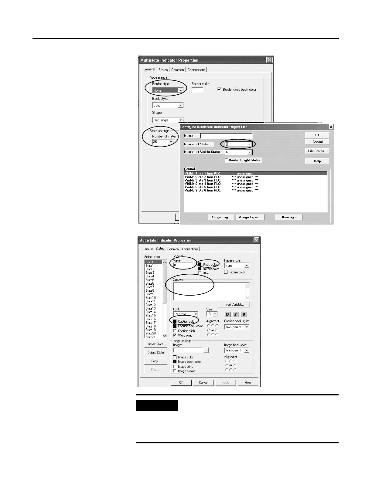
3. Double-click the multistate
object to view its properties.
4. Set the Border style to
None.
When you group the
multistate indicators they
will look as one object with
a continuous border.
5. Under State settings, select
the number of states to
match the original multistate
indicator object list.
The dialog for the original
multistate indicator object
list is shown only for
clarification.
Review Unsupported Features and Implement Workarounds for Migration Issues Chapter 6
6. Click the States tab.
7. For each state, configure
these properties to match
the original multistate
indicator object list.
a. Value
b. Caption
c. Back Color
Apply the foreground color
of the original multistate
indicator object list to the
Caption color for each state
in the new multistate
indicator.
Apply the original
background color to the
Back color of each state in
the new object.
IMPORTANT
Use the same font for each state so that the caption aligns
properly with the cursor of the piloted control list selector.
Move the cursor up and down the piloted control list selector to
verify that the cursor aligns with each multistate indicator.
Adjust if necessary.
Publication 2711P-QS001A-EN-P - October 2007 57
Page 58

Chapter 6 Review Unsupported Features and Implement Workarounds for Migration Issues
8. Click the Connections tab.
The PanelBuilder 1400e
multistate indicator object
list let you configure the
number of visible states. For
each visible state, you then
defined an associated tag
connection.
Because FactoryTalk View
ME does not support this
object, you must assign
each of the ‘Visible State x
from PLC’ connections to a
single multistate indicator.
Create as many multistate
indicators as there are
visible states.
9. Assign the ‘Visible State 1
from PLC’ associated tag to
the Indicator connection.
10. Click OK to accept changes.
FactoryTalk View ME Object
Original PanelBuilder 1400e Object
11. Select the multistate
indicator object and press
Ctrl+C to copy the object.
12. Press Ctrl+V to paste the
copied object.
13. Repeat steps 11 and 12 until
the number of multistate
indicators on the display
matches the number of
visible states.
14. Double-click a copy of the
multistate indicator object to
open its properties.
15. Click the Connections tab.
16. Assign the ‘Visible State 2
from PLC’ associated tag to
the indicator connection.
17. Repeat steps 14 to 16 until
you have assigned the
visible state tag to the
Indicator connection of
each multistate indicator.
58 Publication 2711P-QS001A-EN-P - October 2007
Page 59

1. Resize one of the multistate
indicators so that it aligns
with the cursor of the
piloted control list selector.
2. Continue to resize and align
all multistate indicators so
they appear as a list.
3. Verify that cursor aligns with
the next multistate indicator
when scrolling to the next
state in the piloted control
list selector.
4. Select all multistate
indicators by holding down
the Ctrl key and clicking
each object.
Do not include the piloted
control list selector in the
selection.
Review Unsupported Features and Implement Workarounds for Migration Issues Chapter 6
Resize and Align Multistate Indicators
The easiest way to resize
the multistate indicators is
to divide the height of the
object by the number of
visible states.
5. Select Arrange>Group to
include selected multistate
objects in one group.
When you resize the group,
all individual objects are
automatically resized.
Publication 2711P-QS001A-EN-P - October 2007 59
Page 60

Chapter 6 Review Unsupported Features and Implement Workarounds for Migration Issues
Replacing the Local Message Object List
1. Open the display with the
piloted control list selector.
2. Select Objects>Advanced>
Local Message Display and
draw the object.
In PanelBuilder 1400e software, the local message object list displays
from 2…24 message strings. Because the local message object list
function as a list, it is configured as a group, not individually.
FactoryTalk View ME software provides the local message display as a
replacement for the local message object list. Because the local
message display only allows you to assign a single tag to the object,
you will have to create multiple message displays and group them
together. For example, if the local message object list has four visible
messages, then you will need to create four local message displays
and group them together to achieve the same look.
Create Local Message Displays
Follow these steps to create local message displays.
• The PanelBuilder 1400e
local message object list lets
you assign a tag to each
state (message) you define.
• The FactoryTalk View ME
local message display lets
you assign only a single
indicator tag to the object.
You will need to create as
many local message
displays as there are visible
states (messages) in the
original local message
object list.
60 Publication 2711P-QS001A-EN-P - October 2007
Page 61

3. Double-click the local
message display to open its
properties.
4. Set the Border style to
None.
When you group the local
message displays they will
look as one object with a
continuous border.
5. Set the Back color to match
the background color of the
PanelBuilder 1400e local
message object list.
6. Set the Fore color to match
the foreground color of the
PanelBuilder 1400e local
message object list.
Review Unsupported Features and Implement Workarounds for Migration Issues Chapter 6
7. Set the Font to match the
font used in the
PanelBuilder 1400e
application.
8. Click the ... button under
Message File to select the
‘LocalMsg’ file that was
converted from your
PanelBuilder 1400e
application.
The local message file
contains all of the strings
that will display in the local
message display as the
operator navigates through
the piloted control list
selector.
IMPORTANT
TIP
Use the same font for each local message display so that the
captions align properly with the cursor of the piloted control list
selector. When all message displays are properly aligned,
navigate up and down the piloted control list selector to verify
that the cursor aligns with each local message string.
FactoryTalk View ME software supports multiple local message
files . To improve screen performance you want to create new
local message files from the migrated “LocalMsg” file. You can
link the new message files to the local message objects instead
of having every local message object parse a large file which
decreases screen performance.
Publication 2711P-QS001A-EN-P - October 2007 61
Page 62

Chapter 6 Review Unsupported Features and Implement Workarounds for Migration Issues
9. Click the Connections tab.
The PanelBuilder 1400e
local message object list lets
you configure the number
of visible states. For each
visible state, you then
define an associated tag
connection.
Because FactoryTalk View
ME does not support a local
message object list, you
must assign each of the
‘Visible State x from PLC’
connections to a single local
message display. Create as
many displays as there are
visible states (messages).
10. Assign the ‘Visible State 1
from PLC’ associated tag to
the Value connection.
11. Click OK to accept changes.
FactoryTalk View Object
Original PanelBuilder 1400e Object
12. Select the local message
display object and press
Ctrl+C to copy the object.
13. Press Ctrl+V to paste the
copied object.
14. Repeat steps 11 and 12 until
the number of pasted local
message displays matches
the number of visible states
(messages).
62 Publication 2711P-QS001A-EN-P - October 2007
Page 63

15. Double-click a copy of the
local message display to
open its properties.
16. Click the Connections tab.
17. Assign the ‘Visible State 2
from PLC’ associated tag to
the Value connection.
18. Repeat steps 14 to 16 until
you have assigned the
visible state tag to the Value
connection of each local
message display.
1. Resize one of the local
message displays so that it
aligns with the cursor of the
piloted control list selector.
2. Continue to resize and align
all local message displays so
they appear as a list.
Review Unsupported Features and Implement Workarounds for Migration Issues Chapter 6
Resize and Align the Local Message Displays
The easiest way to resize
the multistate indicators is
to divide the height of the
object by the number of
visible states.
3. Verify that cursor aligns with
the next local message
display when scrolling to
the next state in the piloted
control list selector.
4. Select all local message
displays by holding down
the Ctrl key and clicking
each object.
Do not include the piloted
control list selector in the
selection.
5. Select Arrange>Group to
include selected message
displays in a single group.
When you resize the group,
all individual objects are
automatically resized.
Publication 2711P-QS001A-EN-P - October 2007 63
Page 64

Chapter 6 Review Unsupported Features and Implement Workarounds for Migration Issues
Replacing the Numeric Data Display Object List
1. Open the display with the
piloted control list selector.
2. Select Objects>Numeric and
String>Numeric Display and
draw the object.
In PanelBuilder 1400e software, the numeric data display object list
displays a list of PLC values. The minimum width of the list depends
on the range of values you want to show. This object is retentive
because the scrolling list that controls it is retentive.
FactoryTalk View ME software provides the numeric display object as
an alternative to the numeric data display object list. Because the
numeric display only allows you to assign a single tag to the object,
you will have to create multiple displays and group them together. For
example, if the numeric data display object list has four visible PLC
values, then you will need to create four numeric displays and group
them together to achieve the same look.
Create Numeric Displays
Follow these steps to create numeric displays.
• The PanelBuilder 1400e
numeric data display object
list lets you assign a tag for
each PLC value you want to
display.
• The FactoryTalk View ME
numeric display lets you
assign only a single
indicator tag to the object.
You will need to create as
many numeric displays as
there are visible PLC values
in the original numeric data
display object list.
64 Publication 2711P-QS001A-EN-P - October 2007
Page 65

3. Double-click the numeric
display to open its
properties.
4. Set the Border style to
None.
When you group the
numeric displays they will
look as one object with a
continuous border.
5. Set the Back color to match
the background color of the
PanelBuilder 1400e numeric
data display object List.
6. Set the Fore color to match
the foreground color of the
PanelBuilder 1400e numeric
data display object list.
Review Unsupported Features and Implement Workarounds for Migration Issues Chapter 6
7. Set the Font to match the
font used in the
PanelBuilder 1400e
application.
8. Set the Number of digits to
match the PanelBuilder
1400e numeric data display
object list.
9. Set the number of Decimal
places to match the Digits
after Decimal Point value in
the PanelBuilder 1400e
numeric data display object
list.
IMPORTANT
Original PanelBuilder 1400e Object
The PLC controlled decimal point option is not supported in the
numeric display object. You can use an expression on the
object’s Connections tab to provide similar functionality. For
more information on this workaround, see page 81.
Publication 2711P-QS001A-EN-P - October 2007 65
Page 66

Chapter 6 Review Unsupported Features and Implement Workarounds for Migration Issues
10. Click the Connections tab.
The PanelBuilder 1400e
numeric data display object
list lets you configure the
number of visible states. For
each visible state, you then
define an associated tag
connection.
Because FactoryTalk View
ME does not support a
numeric data display object
list, you must assign each of
the ‘Visible State x from
PLC’ connections to a single
numeric display object.
Create as many numeric
displays as there are visible
states.
11. Assign the ‘Visible State 1
from PLC’ associated tag to
the Value connection.
FactoryTalk View Object
Original PanelBuilder 1400e Object
12. Click OK to accept changes.
13. Select the numeric display
object and press Ctrl+C to
copy the object.
14. Press Ctrl+V to paste the
copied object.
15. Repeat steps 11 and 12 until
number of pasted numeric
displays matches the
number of visible states in
the original PanelBuilder
1400e object.
66 Publication 2711P-QS001A-EN-P - October 2007
Page 67

16. Double-click a copy of the
numeric display to open its
properties.
17. Click the Connections tab.
18. Assign the ‘Visible State 2
from PLC’ associated tag to
the Value connection.
19. Repeat steps 15 to 17 until
you have assigned the
visible state tag to the Value
connection of each numeric
display.
1. Resize one of the numeric
displays so that it aligns
with the arrow of the
piloted control list selector.
2. Continue to resize and align
all numeric displays so they
appear as a list.
Review Unsupported Features and Implement Workarounds for Migration Issues Chapter 6
Resize and Align the Numeric Displays
The easiest way to resize
the multistate indicators is
to divide the height of the
object by the number of
visible states.
3. Verify that the arrow aligns
with the next numeric
display when scrolling to
the next state in the piloted
control list selector.
4. Select all numeric displays
by holding down the Ctrl
key and clicking each
object.
Do not include the piloted
control list selector in the
selection.
5. Select Arrange>Group to
include selected numeric
displays in a single group.
When you resize the group,
all individual objects are
automatically resized.
Publication 2711P-QS001A-EN-P - October 2007 67
Page 68

Chapter 6 Review Unsupported Features and Implement Workarounds for Migration Issues
Replacing the Set Bit Cursor Point Object
1. Extract the downloaded files
to a location on your hard
drive.
In PanelBuilder 1400e software, the set bit cursor point object was
available only on keypad terminals. FactoryTalk View ME software
provides an ActiveX control as an alternative to the set bit cursor point
object. To use this control, you must use a PanelView Plus CE
terminal. The ActiveX control must be registered on the terminal. The
open Windows CE environment of the PanelView Plus CE terminal
allows you to do this.
You must download, register, and configure the ActiveX control in
your FactoryTalk View ME application. See page 46 for the location of
these files.
Register the ActiveX Control on Your Computer
Follow these steps to register the ActiveX control for the set bit cursor
point object on your computer.
2. Open your migrated
application in FactoryTalk
View ME software.
TIP
The Migration Solutions.apa file contains a set bit cursor point
object display which you can test run to review how the object
works.
68 Publication 2711P-QS001A-EN-P - October 2007
Page 69

3. Open a new display.
4. With the display selected,
select Object>ActiveX
Control.
Review Unsupported Features and Implement Workarounds for Migration Issues Chapter 6
5. Draw a box on the display.
You will see ActiveX under
the mouse pointer to
indicate that you are
drawing an ActiveX object.
6. Click the Register button.
Publication 2711P-QS001A-EN-P - October 2007 69
Page 70

Chapter 6 Review Unsupported Features and Implement Workarounds for Migration Issues
7. In the Open dialog:
a. Select the SBCP ActiveX
file (*.ocx) in the Win32
folder where you
extracted files.
b. Click Open to register the
control.
8. Scroll down to the ME SBCP
Control and click OK.
9. Click OK when the warning
appears.
The warning indicates that
you need to load the same
ActiveX control on the
PanelView Plus CE terminal
for runtime operation. You
will do this later.
70 Publication 2711P-QS001A-EN-P - October 2007
Page 71

1. Double-click the ActiveX
control.
2. Click the Connections tab.
3. Assign a tag or expression
to the Select, Index, and
SBCP connections.
The table defines each
connection.
4. Click OK when done.
Review Unsupported Features and Implement Workarounds for Migration Issues Chapter 6
Configure the Set Bit Cursor Point ActiveX Control
Follow these steps to configure the set bit cursor ActiveX control.
Connection Connection type Description
Select Read A zero to non-zero transition activates the control.
• If the value of the Index connection matches an assigned SBCP
connection, the Select connection is set to 1.
• The control becomes inactive if the value of the connection is zero.
This is a required connection.
Index Read The tag assigned to this connection is typically an integer. Set the initial value
to 1. The ActiveX control will mimic behavior similar to the PanelView ‘e’
terminal, which is to select the first item when the control is used the first
time.
A Ramp button pair is typically assigned to the Index connection with the
limits based on the number of cursor points on the display.
This is a required connection.
SBCP Read/Write The SBCP connections are named SBCP1 through SBCP100. Each represents a
value control of the set bit cursor point object in the PanelView ‘e’ terminal.
The SBCP ActiveX control writes either a 0 or 1 to the SBCP connections. Only
one SBCP connection can be set to 1 at a time.
The value of the Index property determines which SBCP connection to set to
1. If the Index connection is set to 1, then SBCP1 is set to 1 and all others are
set to 0.
Publication 2711P-QS001A-EN-P - October 2007 71
Page 72

Chapter 6 Review Unsupported Features and Implement Workarounds for Migration Issues
Migrate the Set Bit Cursor Point Object
Follow these steps to migrate the existing set bit cursor point from
each PanelBuilder 1400e display manually.
1. In the PanelBuilder 1400e
application, open the first
display that uses a set bit
cursor point.
2. In the FactoryTalk View ME
migrated application, open
the same display.
3. In the PanelBuilder 1400e
display, select the first set
bit cursor point the operator
would activate.
4. Double-click the object it to
open its properties.
IMPORTANT
This procedure requires that you open your original
PanelBuilder 1400e application.
5. In the FactoryTalk View ME
display, assign the same tag
from the PanelBuilder 1400e
display (step 3) to the
activeX SBCP connection.
6. Repeat steps 3 and 5 for
each set bit cursor point
object on the display.
7. In FactoryTalk View ME,
assign a digital memory tag
to the Select connection.
TIP
If you require the set bit cursor point to be active when the
operator enters a display, set the initial value of the tag
assigned to the Select connection to 1.
8. Assign an integer memory
tag to the Index connection.
72 Publication 2711P-QS001A-EN-P - October 2007
Page 73

9. Draw four ramp buttons on
the display so the operator
can navigate through each
set bit cursor point object.
Use a left, right, up and
down ramp button.
10. Double-click one of the
ramp buttons and select
properties for a left ramp
button.
a. Set the Ramp down
Lower limit to 1.
b. Set the Ramp value to 1.
c. On the Label tab, set the
Image to Arrow Left.
d. On the Connection tab,
set the Value connection
to the same tag in step 8.
Review Unsupported Features and Implement Workarounds for Migration Issues Chapter 6
Label Tab
Connections Tab
Publication 2711P-QS001A-EN-P - October 2007 73
Page 74

Chapter 6 Review Unsupported Features and Implement Workarounds for Migration Issues
11. Double-click another ramp
button and select properties
for a right ramp button.
a. Set the Ramp down
Upper limit to 100.
Set the upper limit to the
number of set bit cursor
point objects on the
display.
b. Set the Ramp value to 1.
c. On the Label tab, set the
Image to Arrow Right
d. On the Connection tab,
set the Value connection
to the same tag in step 8.
12. Double-click another ramp
button and select properties
for an up ramp button.
a. Set the Ramp down
Lower limit to 1.
b. Set the Ramp value to the
last set bit cursor point
value on the row.
For example, if you have
four set bit cursor points
per row and five rows,
then the ramp value is 4.
In this example, if you
click the Up Ramp button
on the second row at
position 5, you would
expect it to ramp down
by 4, so the set bit cursor
point starts at the first set
bit cursor point on the
first row.
c. On the Label tab, set the
Image to Arrow Up.
d. On the Connection tab,
set the Value connection
to the same tag in step 8.
74 Publication 2711P-QS001A-EN-P - October 2007
Page 75

13. Double-click another ramp
buttons and select
properties for a down ramp
button.
a. Set the Upper limit to the
first set bit cursor point
on the last row.
b. Set the Ramp value to the
last set bit cursor point
value on the row.
For example, if you have
four set bit cursor points
and three rows, then set
the Ramp value to 4 and
the Upper limit to 9.
In this example, if you
clicked the down ramp
button on the second row
at postion 5, it would
ramp up by 4. The set bit
cursor point starts at the
first set bit cursor point
on the next row, 9.
Review Unsupported Features and Implement Workarounds for Migration Issues Chapter 6
c. On the Label tab, set the
Image to Arrow Down.
d. On the Connection tab,
set the Value connection
to the same tag in step 8.
TIP
For keypad only terminals, you need to assign function keys to
each of the ramp arrow buttons so the operator can interact
with the display. Right click an empty area of the display and
select Key Assignments to assign function keys.
Publication 2711P-QS001A-EN-P - October 2007 75
Page 76

Chapter 6 Review Unsupported Features and Implement Workarounds for Migration Issues
14. Add a numeric display to
the display and set the
Value connection to the
same tag in step 8.
The numeric display helps
the operator to identify the
set bit cursor points.
15. Add an interlock push
button to the display, assign
the tag in step 7 to the Value
connection, and set the
button value to 1.
The operator can enable the
ActiveX control by clicking
the interlock push button,
setting the Select connection
value to 1.
16. Add another interlock push
button to the display, assign
the tag in step 7 to the Value
connection, and set the
button value to 0.
The operator can disable
the ActiveX control by
clicking the interlock push
button, setting the Select
connection value to 0.
1. Select
Objects>Indicators>Symbol.
2. Draw a box on the display.
Provide Visual Feedback
76 Publication 2711P-QS001A-EN-P - October 2007
Page 77

3. In the Image Browser, select
Arrow Right and click OK.
4. Double-click the symbol
object to open its
properties.
a. Set the Number of States
to 2.
b. On the States tab,
configure state 0 to have
the same image color and
image back color as the
display.
c. On the Connections tab,
assign the tag assigned to
the Set Bit Cursor Point
SBCP1 connection.
d. Click OK.
Review Unsupported Features and Implement Workarounds for Migration Issues Chapter 6
State Tab
5. Copy and paste the symbol
object for each set bit cursor
point you want on the
display.
Publication 2711P-QS001A-EN-P - October 2007 77
Page 78

Chapter 6 Review Unsupported Features and Implement Workarounds for Migration Issues
6. Repeat step 6 for each
symbol copied in step 8
and assign the SBCPx
connection tags.
In the example, the Select
button enables the set bit
cursor point and the Cancel
button disables it. The
arrows let the operator
navigate through each of
the SBCP tags assigned. In
this example, a symbol
object provides visual
feedback for the object or
tag being referenced.
In Run mode, only one
symbol object is active at a
time, providing visual
feedback to the operator.
7. Repeat all steps starting with
the procedure on page 72
for each display that uses a
set bit cursor point object.
78 Publication 2711P-QS001A-EN-P - October 2007
Page 79

Review Unsupported Features and Implement Workarounds for Migration Issues Chapter 6
Register the ActiveX Control on a PanelView CE Terminal
Follow these steps to install and register the SBCP ActiveX control on
the PanelView Plus CE terminal.
1. Copy the contents of the VVCE41 folder, in the extracted
ME SBCP ActiveX Control folder, to the root of an empty
CompactFlash card.
2. Rename the Install.bat file to Batch.bat.
3. Turn on the PanelView Plus CE terminal without an application
running and
4. Insert a CompactFlash card into the card slot.
The autorun.exe will call the install batch file to install the
necessary files, and register the ActiveX control.
5. Restart the terminal and remove the CompactFlash card after a
display indicates that all the files were copied and registered.
The PanelView Plus CE terminal can now run your application that
requires the set bit cursor point ActiveX control.
Publication 2711P-QS001A-EN-P - October 2007 79
Page 80

Chapter 6 Review Unsupported Features and Implement Workarounds for Migration Issues
Bit Position Data Type Workaround
If a bit position data type does not reference a single bit, it is
converted to an HMI memory tag. An error is recorded in the
conversion log.
• If the object using this data type is an indicator (read operation),
there is a workaround.
• If the object using this data type is a button (write operation),
the feature is unsupported.
The workaround for the bit position data type in an indicator object
(read operation) is to use this expression in the object.
If ((YourTagHere) & 1) ==1 Then 1
Else If ((YourTagHere >> 1) & 1) ==1 Then 2
Else if ((YourTagHere >> 2) & 1) ==1 Then 3
Else if ((YourTagHere >> 3) & 1) ==1 Then 4
Else if ((YourTagHere >> 4) & 1) ==1 Then 5
Else if ((YourTagHere >> 5) & 1)==1 Then 6
Else if ((YourTagHere >> 6) & 1) ==1 Then 7
Else if ((YourTagHere >> 7) & 1) == 1 Then 8
Else if ((YourTagHere >> 8) & 1) ==1 Then 9
Else if ((YourTagHere >> 9) & 1) ==1 Then 10
Else if ((YourTagHere >> 10) & 1) ==1 Then 11
Else if ((YourTagHere >> 11) & 1) ==1 Then 12
Else if ((YourTagHere >> 12) & 1) ==1 Then 13
Else if ((YourTagHere >> 13) & 1) ==1 Then 14
Else if ((YourTagHere >> 14) & 1) ==1 Then 15
Else if ((YourTagHere >> 15) & 1) ==1 Then 16
Else 0
Simply, replace YourTagHere with your bit position tag and the
expression will determine what LSB is high and return its value to the
indicator object.
The expression uses a series of Bit Shift and AND commands to
determine if the LSB is high. If the LSB is high, then depending on the
number of the bit shifts completed, the expression will return a value
associated with the bit location.
For example, if the value of your tag is 500 (111110100 in binary), the
expression will return the value 3 because it is the high LSB.
80 Publication 2711P-QS001A-EN-P - October 2007
Page 81

Review Unsupported Features and Implement Workarounds for Migration Issues Chapter 6
PLC Controlled Decimal Point Workaround
If a numeric object in your PanelBuilder 1400e application was
imported into FactoryTalk View ME software with a PLC controlled
decimal point, an error is recorded in the conversion log.
PLC Controlled Decimal Point input option not supported
As a workaround, use this expression for the Value connection in your
numeric object.
(YourTagHere)/(10 ** (PVe Decimal Point Position Tag))
This expression will let you input a decimal point in a numeric value.
Replace these items in the expression.
• Replace YourTagHere with a tag having a value you want to
display.
• Replace PVe Decimal Point Position Tag with the tag assigned to
the Decimal Point Position connection in the original
PanelBuilder 1400e graphic object.
TIP
Publication 2711P-QS001A-EN-P - October 2007 81
You may need to configure the number of digits the object
displays and the number of decimal places to show depending
on the FactoryTalk View ME object. These fields are typically on
the General tab of the object’s Properties dialog.
Page 82

Chapter 6 Review Unsupported Features and Implement Workarounds for Migration Issues
Fixed Position Decimal Point Workaround
If a numeric object in the PanelBuilder 1400e application was
imported into FactoryTalk View software with a fixed position decimal
point, an error is recorded in the conversion log.
Fixed Position Decimal Point input option not supported
As a workaround, use this expression for the Value connection in your
numeric object.
(YourTagHere)/(10 ** (Fixed Position Value))
This expression will let you input a decimal point in a numeric value.
(YourTagHere)/(10**(Fixed Position Value)
Replace these items in the expression.
• Replace YourTagHere with a tag having a value you want to
display.
• Replace Fixed Position Value with the value defined in the Digits
after Decimal Point field of the original PanelBuilder 1400e
graphic object.
82 Publication 2711P-QS001A-EN-P - October 2007
Page 83

Review Unsupported Features and Implement Workarounds for Migration Issues Chapter 6
Retain Last State Workaround
1. Open your new application
migrated into FactoryTalk
View ME software.
2. In the Explorer window,
expand HMI Tags and
double-click Tags to open
the tag database.
PanelBuilder 1400e software has a Retain the Last State feature for the
cursor list object. If this feature is enabled, when the operator returns
to a display with the cursor list, the last selected state is retained and
reselected. To achieve the same functionality in your FactoryTalk View
ME application, you need to implement this workaround.
• Set up a Display Shutdown macro to write the currently selected
value to a memory tag.
• Set up a Display Startup macro to read the value of the memory
tag and write the value to the Value connection of the piloted
control list selector.
Follows these steps to implement the workaround.
3. Create a new tag.
a. Name the tag
RetainLastState.
b. Set the Tag Type to
Analog.
d. Set the Minimum and
Maximum values to the
number of items the
piloted control list
selector will scroll
through.
e. Select Memory as the
Data Source Type.
f. Set the Initial Value to 0.
g. Verify the Retentive check
box is checked.
4. Click Accept to save the
changes.
Create a similar tag for each
piloted control list selector that
requires the Retain the Last State
feature.
c. Set the Tag Type to Analog.
TIP
The retentive feature retains the last value written to the tag. If
you cycle power to the terminal, the last known value written to
the tag is loaded instead of the Initial value.
Publication 2711P-QS001A-EN-P - October 2007 83
Page 84

Chapter 6 Review Unsupported Features and Implement Workarounds for Migration Issues
5. In the Explorer window,
expand Logic and Control
and double-click Macros.
6. Follow these steps in the
Macro Editor.
a. Under the Tag column,
browse for and select the
RetainLastTag tag.
b. Under Expression,
browse for and select the
tag you assigned to the
Value connection in the
piloted control list
selector.
c. Click Close and then Save
to save your changes.
d. Name the file Retain Last
State.
7. Right-click Macro and select
New.
8. Follow these steps in the
Macro Editor.
a. Under the Tag column,
browse for and select the
tag you assigned to the
Value connection in the
Piloted control list.
b. Under Expression,
browse for and select the
RetainLastTag tag.
c. Click Close and then Yes
to save your changes.
d. Name the file Restore Last
State.
84 Publication 2711P-QS001A-EN-P - October 2007
Page 85

9. Double-click the display
with the piloted control list
selector that requires the
Retain the Last State feature.
10. Right-click an empty area of
the screen and select
Display Settings.
11. Click the Behavior tab.
Review Unsupported Features and Implement Workarounds for Migration Issues Chapter 6
12. Click the ... button under
Macros startup to browse
for and select the Restore
Last State macro file.
13. Click the ... button under
Macros shutdown to browse
for and select the Restore
Last State macro file.
14. Click OK to accept the
changes.
15. Click X on the display and
save all changes.
TIP
You will need to repeat this procedure for each piloted control
list selector that requires the Retain the Last State feature. This
includes the creation of new tags and new macro files.
You have completed the workaround for the Retain the Last State
feature. When you open a display with a piloted control list selector,
the startup display macro restores the state value from the
RetainLastState tag to the Value connection of the piloted control list
selector. When you navigate to a different display, the shutdown
macro copies the last state value of the piloted control list selector to
the RetainLastState tag.
Publication 2711P-QS001A-EN-P - October 2007 85
Page 86

Chapter 6 Review Unsupported Features and Implement Workarounds for Migration Issues
Ladder Logic Updates to Support Visible States
1. Create a new data file.
2. Configure these parameters
for the data file.
a. Accept the File value.
b. Set the Type to Integer.
c. Enter a meaningful Name
for the file.
d. For Elements, enter the
number of visible states
in the original
PanelBuilder 1400e
cursor list object.
e. Click OK to save your
settings.
Because the piloted control list selector uses an array tag, not
individual tags, to implement visible states, you need to make changes
to your ladder logic.
Follow these steps to update your ladder logic using RSLogix 5
software. The same steps would apply if using RSLogix 500 sofware.
3. Right-click on Program Files
and select New to add a
new program file to the PLC
program.
86 Publication 2711P-QS001A-EN-P - October 2007
Page 87

4. Configure these parameters
for the program file.
a. Accept the Number
value.
b. Set the File Type to
Ladder File.
c. Enter a meaningful Name
for the program file.
d. Click OK to save your
settings.
5. Double-click the program
file you just created.
Review Unsupported Features and Implement Workarounds for Migration Issues Chapter 6
6. On the tabbed instruction
bar, select the Move/Logic
tab and click MOV.
7. Configure the MOV
instruction.
a. For Source, enter the first
word location in the new
data file you just created.
b. For Destination, enter the
tag address for the
original Visible State 1 to
PLC connection.
8. Click the next empty rung.
9. Repeat steps 6 to 8 until the
number of MOV instructions
matches the number of
visible states in the original
control list object.
As you repeat each step,
enter the next word in the
data file for the Source and
the next visible state as the
Destination.
Publication 2711P-QS001A-EN-P - October 2007 87
Page 88

Chapter 6 Review Unsupported Features and Implement Workarounds for Migration Issues
10. Click the next empty rung.
11. On the tabbed instruction
bar, select the Program
Control tab and click RET.
The RET command exits the
subroutine and returns you
to the MAIN program.
12. Click X an save your
changes.
13. Double-click your main
program file.
14. Click the last rung.
15. On the tabbed instruction
bar, select the Program
Control tab and click JSR.
16. The JSR instruction jumps to
the subroutine that handles
all the visible state MOV
instructions just created.
17. In the JSR subroutine, set
the Prog File Number to the
number specified in the
Program File that handles all
the MOV instructions.
18. Click X to save all changes.
88 Publication 2711P-QS001A-EN-P - October 2007
Page 89

19. On the Connections tab of
your piloted control list
selector, assign the
appropriate tag to the
Visible States connection.
Review Unsupported Features and Implement Workarounds for Migration Issues Chapter 6
This is the address syntax for the Visible States tag.
{[PLC5]N7:0,L5}
Replace With
N7:0 The first element in the data file you created.
5 in L5 The number of elements you entered in the new data file or the
number of visible states in the original cursor list object.
PLC5 Shortcut name you defined in Communication Setup of RSLinx
Enterprise software.
The visible state ladder logic changes are now complete.
• When the Main Routine runs, the JSR instruction jumps to the
new program file you created.
• In the new program file, the FactoryTalk View ME piloted
control list selector writes the visible states into the elements of
the new data file you created.
• The ladder logic in the program file moves the contents of the
elements into the original Visible State x to PLC tags that were
defined in the cursor list object, and then returns to the Main
Routine.
Publication 2711P-QS001A-EN-P - October 2007 89
Page 90

Chapter 6 Review Unsupported Features and Implement Workarounds for Migration Issues
90 Publication 2711P-QS001A-EN-P - October 2007
Page 91

Qualify the Runtime Application
Chapter
7
Introduction
Before You Begin
In this chapter, you will qualify the integrity of your converted
application before downloading and running it in your production
environment. Because you are using different software with new
features and functionality, it is important to validate the application for
proper operation.
• Review migration considerations (Chapter 1).
• Select a PanelView Plus terminal replacement and adapter plate,
if required (Chapter 2).
• Optionally install the PanelView Plus terminal in the existing
PanelView 1000e or 1400e panel cutout (Chapter 2).
• Import your PanelBuilder 1400e .pvc application into
FactoryTalk View ME software (Chapter 3).
• Review the conversion log for your migrated application
(Chapter 4).
• Review object and expression mapping (Chapter 5).
• Review unsupported features and common migration issues
(Chapter 6).
What You Need
91Publication 2711P-QS001A-EN-P - October 2007 91
Converted FactoryTalk ME application with unsupported features and
workarounds for migration issues.
Page 92

Chapter 7 Qualify the Runtime Application
Follow These Steps
Follow these steps to configure diagnostics, validate, test run,
configure global memory connections, download, and run your
converted application on a PanelView Plus terminal.
Reviewing Diagnostic
Lists
page 93
Configure the Runtime
Diagnostic Display
page 94
Reviewing Error States
for Graphic Objects
page 95
Test Run Graphic
Displays
page 96
Test Run the Application
Configuring Global
Memory Connections
Configuring
Communication
page 98
page 99
page 102
92 Publication 2711P-QS001A-EN-P - October 2007
Page 93

Qualify the Runtime Application Chapter 7
Reviewing Diagnostic Lists
On your development computer, FactoryTalk View ME software
features a diagnostic list at the bottom of the application window. You
can configure FactoryTalk diagnostics to display information,
warnings, and errors during application development and runtime
operation.
When you test run your application, the diagnostic list displays
messages and errors logged by the application. Use this list to identify
the graphic objects or features that generated the messages or errors.
Correct these errors during the validation process.
The diagnostic lists lets you Clear one or all messages in the list.
• Click the Clear button to delete the message that is displayed. If
you resize the list to display more than one message, select a
message and then click Clear.
• Click the Clear All button to delete all messages in the list.
To view this diagnostic information during runtime, use either the
• default [DIAGNOSTICS] graphic display
• or diagnostic list object in a customized graphic display.
TIP
The [DIAGNOSTICS] display is in the Libraries editor
of the application Explorer window if not already
included in your application displays. Import the
[DIAGNOSTIC] display if you are going to use it.
Publication 2711P-QS001A-EN-P - October 2007 93
Page 94

Chapter 7 Qualify the Runtime Application
Configure the Runtime Diagnostic Display
1. Launch FactoryTalk View
ME if not open.
2. Open your converted
application.
3. Expand the System folder in
your application Explorer
window.
4. Double-click Diagnostic List
Setup.
5. Under Runtime display,
verify that [DIAGNOSITICS]
is the Display name.
Follows these steps to configure the default [DIAGNOSTICS] display to
log errors or warnings generated during runtime operation.
This is the default diagnostic
display that pops up during
runtime when configured
events occur.
6. Check the boxes next to the
the messages that you want
to appear in the display
when events occur during
runtime.
Always log errors and
warnings during runtime.
For information on how
each dialog option is
designed to function during
runtime, click Help.
7. Click OK.
94 Publication 2711P-QS001A-EN-P - October 2007
Page 95

Qualify the Runtime Application Chapter 7
Reviewing Error States for Graphic Objects
In FactoryTalk View ME software, error conditions for visible objects
may be different than those in PanelBuilder 1400e software. The
Object Error Mode table clarifies what happens when errors occur for
objects when tags are unavailable or communication is lost.
For additional information on objects, refer to the online help.
Object Error Mode
Graphic Object Visible Error Mode
• Momentary Push Button
• Maintained Push Button
• Latched Push Button
• Multistate Push Button
• Interlock Push Button
• Ramp Push Button
• Numeric Display
• Numeric Input Cursor
• Numeric Input Enable
• String Input Enable
• String Display
• Goto Display Button
• Return To Display Button
• Display List Selector
• Close Display Button
Multistate Indicator The caption displays Error for the error
Symbol Properties The object shows the image color defined in
List Indicator No visible error message or error condition
Bar Graph Gauge This object shows a transparent wireframe
Scale No visible error message or error condition
Local Message Display This object displays question marks,
The caption displays ‘default error
message’ for the error state.
No visible error message or error condition
is displayed.
When you click on these objects, an error
message is generated and logged to the
diagnostic list object.
These objects display asterisks, ******.
No visible error message or error condition
is displayed.
When you click on these objects, an error
message is generated and logged to the
diagnostic list object.
No visible error message or error condition
is displayed.
If communication to the PLC controller is
lost, these buttons still let you navigate
through your application.
state.
the error state.
is displayed.
box.
is displayed.
???????, in the error state.
Publication 2711P-QS001A-EN-P - October 2007 95
Page 96

Chapter 7 Qualify the Runtime Application
Object Error Mode
Graphic Object Visible Error Mode
• Backspace
• End
• Enter
• Home
• Move Left
• Move Right
• Move Down
• Page Up
• Page Down
• Sort Alarm
• Reset Alarm
• Alarm Banner
• Alarm Status List
Display Print No visible error message or error condition
Trend This object appears not to have any pens
Time and Date No visible error message or error condition
No visible error message or error condition
is displayed.
No visible error message or error condition
is displayed.
is displayed.
and does not perform real-time trending.
is displayed.
Test Run Graphic Displays
FactoryTalk View ME software provides a Test Display mode to test
the animation and assigned tags connected to objects in a graphic
display. Any information, warning, or errors are logged to the
diagnostic list for your review.
Test Display mode tests all objects in a display:
• Button objects
• Numeric and string object to verify that correct values are
displayed
• Objects that require user input
• Objects that use animation
For each object tested, review and correct any errors and warnings
logged to the diagnostic list. Retest the display object before
proceeding to the next object.
IMPORTANT
In Test Display mode, objects in the display are activated and
connected to assigned tags. Only tags connected to objects in
the display will work. Links to other displays or alarms,
including data logging, macros, global connections, and
information messages will not work. Configure communication
to the PLC controller before test running the display or all
objects will show their error states.
96 Publication 2711P-QS001A-EN-P - October 2007
Page 97

1. Open the display you want
to test.
2. Access Test Display mode in
one of two ways.
• Choose Test Display from
the View menu
Qualify the Runtime Application Chapter 7
Follow these steps to activate Test Display mode for a display and
then return to Edit mode. Running Test Display mode and correcting
logged errors in Edit mode is an iterative process.
• or click the Test Display
button on the toolbar.
3. Return to Edit mode in one
of two ways.
• Choose Edit Display from
the View menu
• or click the Edit Display
button on the toolbar.
Publication 2711P-QS001A-EN-P - October 2007 97
Page 98

Chapter 7 Qualify the Runtime Application
Test Run the Application
1. Open your converted
application in FactoryTalk
View ME software.
2. Test the application in one
of two ways.
• Choose Test Application
from the Application menu
After testing and verifying that each graphic display is error free, you
are ready to test run the entire application. Application Test mode lets
you navigate through the entire application to validate functions not
tested in Display Test mode. Some of these features include alarming,
data logging, information messages, global connections, and macros.
As you navigate through displays in Application Test mode, the
Diagnostic List logs warnings and errors as they occur. Correct all
logged errors and then retest the application to validate error
correction.
Follow these steps to test run an application.
• or click the Test Application
icon on the toolbar.
The emulator opens on your
computer and runs the
application. There is a two
hour limit for using the
runtime emulator.
3. Press x on your keyboard to
exit the emulator.
TIP
TIP
Local messages and graphic objects configured for multiple
languages will display in the application’s current language
while in Test Application mode.
The emulator window requires focus when pressing the x key to
exit the emulator.
98 Publication 2711P-QS001A-EN-P - October 2007
Page 99

Qualify the Runtime Application Chapter 7
Configuring Global Memory Connections
FactoryTalk View ME software provides global connections to monitor
the memory usage of an application during runtime.
• MERuntime Memory Usage - This is a new option.
• Available RAM
• Total RAM Usage
IMPORTANT
When developing and testing a FactoryTalk View ME
application on the PanelView Plus terminal, monitor the values
of these connections to verify that the application does not
exceed the available RAM installed in the terminal.
Hardware Limitations
PanelView Plus terminals have a 32 MB process limit. The application
cannot consume more than 32 MB of memory at runtime. Run the
application on the PanelView Plus terminal with the MERuntime RAM
Usage connection enabled to determine if the application is
approaching this limit. Navigate to all screens and exercise all
functions of the application to monitor memory usage.
IMPORTANT
If the MERuntime RAM Usage exceeds 26 MB for the application and
performance is slow, you can do one of two things:
• Modify the application to reduce memory usage.
• Move the application to a PC-based industrial computer.
When running an application on a PanelView Plus terminal,
FactoryTalk View ME Station has a tag connection cache
threshold of 26 MB. If the MERuntime RAM Usage exceeds 26
MB, screen change performance decreases significantly as the
system adds and removes tag connections from the cache.
Publication 2711P-QS001A-EN-P - October 2007 99
Page 100

Chapter 7 Qualify the Runtime Application
1. Open your converted
application in FactoryTalk
View ME software.
2. In the Explorer window,
double-click the Global
Connections icon.
The Global Connections
editor opens.
Configure Global Connections
Follow these steps to set up global memory connections in your
converted application.
3. Click the Memory tab.
100 Publication 2711P-QS001A-EN-P - October 2007
 Loading...