

Page 1

Hardware Reference, Installation, and Troubleshooting Manual D2-3411-8
LiquiFlo AC Power Modules
Version 6.4
Page 2

Important User Information
IMPORTANT
Solid-state equipment has operational characteristics differing from those of electromechanical equipment. Safety
Guidelines for the Application, Installation and Maintenance of Solid State Controls (publication SGI-1.1
your local Rockwell Automation sales office or online at http://www.rockwellautomation.com/literature/
important differences between solid-state equipment and hard-wired electromechanical devices. Because of this difference,
and also because of the wide variety of uses for solid-state equipment, all persons responsible for applying this equipment
must satisfy themselves that each intended application of this equipment is acceptable.
In no event will Rockwell Automation, Inc. be responsible or liable for indirect or consequential damages resulting from the
use or application of this equipment.
The examples and diagrams in this manual are included solely for illustrative purposes. Because of the many variables and
requirements associated with any particular installation, Rockwell Automation, Inc. cannot assume responsibility or
liability for actual use based on the examples and diagrams.
No patent liability is assumed by Rockwell Automation, Inc. with respect to use of information, circuits, equipment, or
software described in this manual.
Reproduction of the contents of this manual, in whole or in part, without written permission of Rockwell Automation,
Inc., is prohibited.
Throughout this manual, when necessary, we use notes to make you aware of safety considerations.
available from
) describes some
WARNING: Identifies information about practices or circumstances that can cause an explosion in a hazardous environment,
which may lead to personal injury or death, property damage, or economic loss.
ATTENTION: Identifies information about practices or circumstances that can lead to personal injury or death, property
damage, or economic loss. Attentions help you identify a hazard, avoid a hazard, and recognize the consequence.
SHOCK HAZARD: Labels may be on or inside the equipment, for example, a drive or motor, to alert people that dangerous
voltage may be present.
BURN HAZARD: Labels may be on or inside the equipment, for example, a drive or motor, to alert people that surfaces may
reach dangerous temperatures.
ARC FLASH HAZARD: Labels may be on or inside the equipment, for example, a motor control center, to alert people to
potential Arc Flash. Arc Flash will cause severe injury or death. Wear proper Personal Protective Equipment (PPE). Follow ALL
Regulatory requirements for safe work practices and for Personal Protective Equipment (PPE).
Identifies information that is critical for successful application and understanding of the product.
Allen-Bradley, Rockwell Software, Rockwell Automation, and TechConnect are trademarks of Rockwell Automation, Inc.
Trademarks not belonging to Rockwell Automation are property of their respective companies.
Page 3

Chapter 1
Chapter 2
C
ONTENTS
Introduction
1.1 Related Publications ........................................................................................ 1-1
1.2 Getting Assistance from Reliance Electric....................................................... 1-1
About the Drive
2.1 Identifying the Drive by Model Number ........................................................... 2-1
2.2 Enclosure Ratings ........................................................................................... 2-2
2.3 B-Frame LiquiFlo Drive Component Locations................................................ 2-2
2.4 C-Frame LiquiFlo Drive Component Locations ............................................... 2-4
2.5 D-Frame LiquiFlo Drive Component Locations ............................................... 2-6
2.6 Regulator Board Description ........................................................................... 2-8
2.6.1 Jumper Locations and Settings ........................................................... 2-10
2.6.1.1 Setting the Analog Input Speed Reference Jumper (J4) ...... 2-10
2.6.1.2 Setting the Analog Output Jumper (J17)............................... 2-11
2.6.2 Wiring the Regulator Board Terminal Strip.......................................... 2-12
2.6.3 RS-232 Communication Port............................................................... 2-13
2.6.4 RMI Board Connector ......................................................................... 2-13
2.6.5 Operator Interface Module Connector................................................. 2-14
2.6.6 Keypad/Display ................................................................................... 2-14
2.7 RMI Board Description .................................................................................. 2-15
2.7.1 Digital Inputs ....................................................................................... 2-15
2.7.2 Digital Outputs..................................................................................... 2-15
2.7.3 Relay Outputs ..................................................................................... 2-15
2.7.4 Analog Input ........................................................................................ 2-15
2.7.5 Analog Outputs ................................................................................... 2-15
2.7.6 Frequency Input .................................................................................. 2-15
2.7.7 Wiring the RMI Board Terminal Strip................................................... 2-16
2.8 Optional Equipment ....................................................................................... 2-17
Contents
Chapter 3
Planning the Installation
3.1 General Requirements for the Installation Site ................................................ 3-1
3.1.1 Making Sure Environmental Conditions are Met ................................... 3-1
3.1.2 Determining Total Area Required Based on Drive Dimensions ............ 3-2
3.1.3 Verifying the Site Provides for Recommended Air Flow Clearances .... 3-6
3.1.4 Verifying Power Module Input Ratings Match Supplied Power ............. 3-6
3.2 Wiring Requirements for the Drive .................................................................. 3-6
3.2.1 Meeting Terminal Strip Input and Output Specifications ....................... 3-6
3.2.2 Determining Wire Size Requirements ................................................... 3-6
3.2.2.1 Conduit Entry Opening Sizes .................................................. 3-6
3.2.2.2 Recommended Power Wire Sizes .......................................... 3-6
3.2.2.3 Recommended Control and Signal Wire Sizes ....................... 3-7
3.2.2.4 Recommended Motor Lead Lengths....................................... 3-8
3.2.2.5 Recommended Serial Communication Cable Lengths ........... 3-8
3.2.3 Selecting Input Line Branch Circuit Fuses ............................................ 3-8
3.2.4 Meeting Encoder Specifications (FVC Regulation Only)....................... 3-9
3.2.4.1 Encoder Wiring Guidelines ..................................................... 3-9
3.2.5 Verifying Power Module Output Current Rating Is
Greater Than Motor Full Load Amps..................................................... 3-9
I
Page 4

Chapter 4
Chapter 5
Chapter 6
Mounting the Drive, Grounding, and Finding Wire Routing Locations
4.1 Lifting and Mounting the Drive .........................................................................4-1
4.1.1 Verifying the Drive’s Watts Loss Rating.................................................4-2
4.2 Determining Input, Motor Output, Ground, and Control Wire
Routing for the Drive ........................................................................................4-2
4.3 Installing the DC Bus Reactor Fan (C-Frame Drives Only)..............................4-6
4.4 Grounding the Drive .........................................................................................4-7
4.5 Connecting Coolant Lines ................................................................................4-7
4.5.1 B-Frame Coolant Connections ..............................................................4-7
4.5.2 C-Frame Coolant Connections ..............................................................4-7
4.5.3 D-Frame Coolant Connections ..............................................................4-8
Installing Input Power Wiring
5.1 Installing Transformers and Reactors (Optional) .............................................5-1
5.2 Installing Fuses for Branch Circuit Protection ..................................................5-1
5.3 Installing a Required External/Separate Input Disconnect...............................5-4
5.4 Installing Power Wiring from the AC Input Line to the
Drive’s Power Terminals ..................................................................................5-4
Installing Output Power Wiring
6.1 Installing Output Contactors (Optional) ............................................................6-1
6.2 Installing Mechanical Motor Overload Protection (Optional) ............................6-1
6.3 Installing Output Wiring from the Drive Output Terminals to the Motor............6-2
Chapter 7
Chapter 8
Chapter 9
Appendix A
Appendix B
Wiring the Regulator Board and RMI Board Terminal Strips
7.1 Stopping the Drive............................................................................................7-7
7.2 Wiring the Encoder Feedback Device
(FVC Regulation Only)8
7.3 Wiring the Signal and Control I/O...................................................................7-10
7.4 Wiring the RMI Board Terminal Strip .............................................................7-19
Completing the Installation
8.1 Checking the Installation ..................................................................................8-1
8.2 Powering Up After Installation Is Complete......................................................8-2
Troubleshooting the Drive
9.1 Test Equipment Needed To Troubleshoot .......................................................9-1
9.2 Drive Alarms and Faults...................................................................................9-1
9.3 Verifying That DC Bus Capacitors Are Discharged..........................................9-1
9.4 Checking the Power Modules with Input Power Off .........................................9-5
9.5 Replacement Parts...........................................................................................9-7
Technical Specifications........................................................................................... A-1
Cooling System Specifications................................................................................. B-1
Appendix C
B-Frame LiquiFlo Drive Wiring Diagrams................................................................. C-1
II
LiquiFlo AC Power Modules, Hardware Reference Version 6.4
Page 5

Appendix D
Appendix E
C-Frame LiquiFlo Drive Wiring Diagrams .................................................................D-1
D-Frame LiquiFlo Drive Wiring Diagrams .................................................................E-1
Contents
III
Page 6

IV
LiquiFlo AC Power Modules, Hardware Reference Version 6.4
Page 7

List of Figures
Figure 2.1 – Identifying the Drive Model Number ..................................................... 2-1
Figure 2.2 – B-Frame LiquiFlo Drive Component Locations..................................... 2-3
Figure 2.3 – C-Frame LiquiFlo Drive Component Locations .................................... 2-5
Figure 2.4 – D-Frame LiquiFlo Drive Component Locations .................................... 2-7
Figure 2.5 – LiquiFlo Regulator Board Component Locations.................................. 2-9
Figure 2.6 – Jumper J4 Settings for Analog Input Speed Reference ..................... 2-11
Figure 2.7 – Jumper J17 Settings for Analog Outputs............................................ 2-12
Figure 2.8 – Typical Regulator Board Terminal Strip Connections......................... 2-13
Figure 2.9 – Keypad/Display................................................................................... 2-14
Figure 2.10 – Terminal Connections on the RMI Board ......................................... 2-16
Figure 3.1 – B-Frame Drive Dimensions .................................................................. 3-3
Figure 3.2 – C-Frame Drive Dimensions .................................................................. 3-4
Figure 3.3 – D-Frame Drive Dimensions .................................................................. 3-5
Figure 4.1 – Wire Routing Locations for B-Frame LiquiFlo Drives ........................... 4-3
Figure 4.2 – Wire Routing Locations for C-Frame LiquiFlo Drives ........................... 4-4
Figure 4.3 – Wire Routing Locations for D-Frame LiquiFlo Drives ........................... 4-5
Figure 4.4 – DC Bus Reactor Cooling Fan Mounting Location ................................. 4-6
Figure 4.5 – Coolant Connector Locations for B-Frame LiquiFlo Drives .................. 4-8
Figure 4.6 – Coolant Connector Locations for C-Frame LiquiFlo Drives .................. 4-9
Figure 4.7 – Coolant Connector Locations for D-Frame LiquiFlo Drives .................. 4-9
Figure 5.1 – Typical AC Input/Output Electrical Connections
(6-Pulse Rectifier, All Frames)................................................................ 5-2
Figure 5.2 – Typical AC Input/Output Electrical Connections
(12-Pulse Rectifier, B- and C-Frames Only) ........................................... 5-3
Figure 7.1 – Two-Wire Start/Stop Sample Control Wiring ........................................ 7-5
Figure 7.2 – Three-Wire Start/Stop Sample Control Wiring...................................... 7-6
Figure 7.3 – Encoder Wiring Connections ................................................................ 7-9
Figure 7.4 – Terminal Connections on the RMI Board ........................................... 7-19
Figure 9.1 – DC Bus Voltage Terminals (B-Frame Drives)....................................... 9-2
Figure 9.2 – DC Bus Voltage Terminals (C-Frame Drives) ...................................... 9-3
Figure 9.3 – DC Bus Voltage Terminals (D-Frame Drives) ...................................... 9-4
Contents
V
Page 8

VI
LiquiFlo 2.0 AC Drive User Manual
Page 9

List of Tables
Table 2.1 – Power and Enclosure Ratings ............................................................... 2-2
Table 2.2 – Available Kits and Options................................................................... 2-17
Table 3.1 – Environmental Conditions...................................................................... 3-2
Table 3.2 – Drive Dimensions and Weights.............................................................. 3-2
Table 3.3 – Recommended Power Wire Sizes for B-Frame Drives.......................... 3-7
Table 3.4 – Recommended Power Wire Sizes for C-Frame Drives ......................... 3-7
Table 3.5 – Recommended Power Wire Sizes for D-Frame Drives ......................... 3-7
Table 3.6 – Recommended Terminal Strip Wire Sizes............................................. 3-8
Table 3.7 – AC Input Line Fuse and Circuit Breaker Selection Values .................... 3-9
Table 5.1 – Terminal Tightening Torques................................................................. 5-4
Table 7.1 – RS-232 Connections (Terminals 1-3) .................................................... 5-1
Table 7.2 – Encoder Connections (Terminals 4-9) ................................................... 7-1
Table 7.3 – Analog Output Connections (Terminals 10 and 11)............................... 7-2
Table 7.4 – Analog Speed/Torque Reference Connections (Terminals 12-15)........ 7-2
Table 7.5 – Digital Input Connections (Terminals 16-25) ......................................... 7-3
Table 7.6 – Reserved Connections (Terminals 26 and 27) ...................................... 7-3
Table 7.7 – Status Relay Connections (Terminals 28-31) ........................................ 7-4
Table 7.8 – Wiring Signal and Control I/O to the Regulator Board Terminal Strip.. 7-10
Table 7.9 – Wiring Signal and Control I/O to the RMI Board Terminal Strip........... 7-20
Table 9.1 – Resistance Checks ................................................................................ 9-6
Table 9.2 – B-Frame LiquiFlo Drive Replacement Parts .......................................... 9-7
Table 9.3 – C-Frame LiquiFlo Drive Replacement Parts .......................................... 9-8
Table 9.4 – D-Frame LiquiFlo Drive Replacement Parts .......................................... 9-9
Contents
VII
Page 10

VIII
LiquiFlo 2.0 AC Drive User Manual
Page 11

This instruction manual describes the LiquiFlo™ drive’s Power Module and regulator
hardware. It does not cover the LiquiFlo software. For software information, refer to the
LiquiFlo AC General Purpose (V/Hz) and Vector Duty Drive Software Start-Up and
Reference Manual (D2-3410).
This manual is intended for qualified electrical and plumbing personnel.
LiquiFlo drives will typically be referenced by frame size. If additional clarity is
required, drive model numbers wil also be included.
1.1 Related Publications
Refer to the following related publications as necessary for more information:
• D2-3410 - LiquiFlo AC General Purpose (V/Hz) and Vector Duty Drive Software
Start-Up and Reference Manual
• D2-3305 - Motor Encoder Cable Kit
C
HAPTER
Introduction
1
• D2-3348 - Control and Configuration Software (CS3000)
• D2-3341 - Remote Meter Interface Board
• D2-3342 - Operator Interface Module
• D2-3449 - LiquiFlo AC Drive Panel Mount Kit
1.2 Getting Assistance from Reliance Electric
If you have any questions or problems with the products described in this instruction
manual, contact your local Reliance Electric sales office. For technical assistance, call
1-864-284-5444.
Introduction
1-1
Page 12

1-2
LiquiFlo AC Power Modules, Hardware Reference Version 6.4
Page 13

C
HAPTER
About the Drive
This chapter describes how to identify the drive using the model number matrix and
shows the major drive components.
The LiquiFlo AC drive is a PWM (pulse-width-modulated) liquid-cooled drive that
provides vector and general purpose regulation for a wide range of applications.
Using vector regulation, the drive can provide high dynamic response, maintain full
rated motor torque to zero speed, and precisely control motor speed in both
directions. The drive can provide this functionality either with encoder feedback (flux
vector control or FVC) or without (sensorless vector control or SVC).
Using general purpose (volts/hertz or V/Hz) regulation, the drive is suited for a broad
range of applications requiring adjustable speed control of motors.
2.1 Identifying the Drive by Model Number
Each LiquiFlo AC drive can be identified by its model number. See figure 2.1. This
number appears on the shipping label and on the drive’s nameplate. The drive’s model
number includes the Power Module and the regulator version. Drive power ratings are
provided in table 2.1.
2
Continuous Ampere Rating (x10)
41 = 414 amps
50 = 500 amps
64 = 643 amps
120 = 1200 amps
LW= water-cooled
LR = refrigerant-cooled
Voltage
2 = 200 to 230 VAC
3 = 270 to 310 VAC
4 = 380 to 480 VAC
Enclosure
0 = Open Chassis
1 = NEMA 1
2 = NEMA 12 Only
4 = NEMA 4x (Indoor Only) or NEMA 12
Regulator V e rsio n
60 = Version 6.x Firmware
Figure 2.1 – Identifying the Drive Model Number
NNN AA N N NN
About the Drive
2-1
Page 14

Table 2.1 – Power and Enclosure Ratings
Frame Size and
Model
Number
41L4060
41LR4060
50LW4060
50LR4060
64LW4060
64LR4060
120L4060 D-Frame
* With V/Hz regulation, 110% continuous output current capability. With vector regulation, 150% output current capability for 5 sec.
**Note that LiquiFlo drives are rated for use with water at specified temperatures and pressures as the coolant. Some coolant fluids may
allow an increased output rating while others may require the output to be derated. The LiquiFlo drive is also capable of running at 4 kHz
or 8 kHz. Contact Reliance Electric for ratings.
Selected
Regulation*
B-Frame
V/Hz or Vector
C-Frame
V/Hz or Vector
C-Frame
V/Hz or Vector
V/Hz or Vector
Enclosure
Rating
Open-Chassis
Style
Open-Chassis
Style
Open-Chassis
Style
Open-Chassis
Style
Input
Power
(KVA)
344 414 414 4600 / 1100
398 500 500 5500 / 1500
512 643 643 7000 / 2000
956 1200 1200 11700/4000
Input
Current
(Amps)
Output Current
at 2 kHz**
(Amps)
Full Load
Power Loss Watts
Fluid / Air
2.2 Enclosure Ratings
LiquiFlo drives have the following enclosure rating:
• Open-Chassis Style: Intended to be installed in an enclosure.
LiquiFlo drives must be placed in an enclosure.
2.3 B-Frame LiquiFlo Drive Component Locations
The B-Frame LiquiFlo drives have the following main components. The numbered
items listed below provided correspond to the numbers used in figure 2.2.
Replacement parts are listed in chapter 9.
1. Bus Bars (3) (AC Output)
2. Bus Bars (6) (AC Input)
3. IGBT Modules
4. Output Laminate
5. Capacitors
6. RMI Board
7. Casting
8. Membrane Switch Keypad
9. Coolant Lines - (a) Inlet, (b) Outlet
10. Regulator Board
11. Power Module Control (PCB)
12. Current Feedback Devices (3)
2-2
LiquiFlo AC Power Modules, Hardware Reference Version 6.4
Page 15

1
2
3
12
9b
4
11
5
10
9a
About the Drive
8
7
6
Figure 2.2 – B-Frame LiquiFlo Drive Component Locations
2-3
Page 16

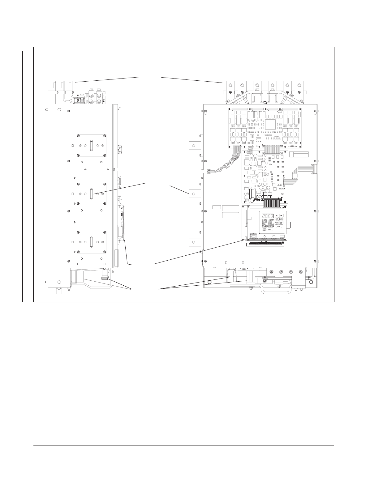
2.4 C-Frame LiquiFlo Drive Component Locations
The C-Frame LiquiFlo drives have the following main components. The numbered
items listed below provided correspond to the numbers used in figure 2.3.
Replacement parts are listed in chapter 9.
1. Bus Bars (AC Input)
2. SCR Bridge (AC to DC Converter)
3. Power Module Adapter Printed Circuit Board (PCB)
4. Power Interface Harness
5. Bus Bars (AC Output)
6. LEM InterfaceHarness
7. DC Bus Control PCB
8. Gate Driver PCB -Low Side
9. DC Bus Laminate Assembly
10. Output Current Feedback Devices
11. IGBT Modules
12. Chillplate (Heatsink)
13. Capacitors
14. Drive Baseplate
15. Reactor (Not Shown)
16. Discharge Resistors (Not Shown)
17. Control Panel Assembly
18. Bus Control - PMA Harness
19. Bus Control - Gate Drive Harness
20. Gate Driver PCB- High Side (Not Shown)
21. Membrane Switch Keyboard/Bracket
22. Regulator PCB
23. Option Board (Optional)
24. Coolant Lines - (Not Shown)
2-4
LiquiFlo AC Power Modules, Hardware Reference Version 6.4
Page 17

16
1
2
3
17
4
5
10
12
11
6
7
8
9
18
19
20
21
22
23
13
About the Drive
14
15
Figure 2.3 – C-Frame LiquiFlo Drive Component Locations
24
2-5
Page 18

2.5 D-Frame LiquiFlo Drive Component Locations
The D-Frame LiquiFlo drives have the following main components. The numbered
items listed below provided correspond to the numbers used in figure 2.4.
Replacement parts are listed in chapter 9.
1. Chillplate Harness
2. Bus Bars (AC Input)
3. Bus Bars (AC Output)
4. Power Module Control PCB
5. Membrane Switch Keypad
6. Regulator PCB
7. RMI Option PCB
8. Current Feedback Devices
9. Gate Driver PCB
10. Coolant Connection (Outlet)
11. IGBT Module
12. Capacitors
13. Coolant Connection (Inlet)
14. Output Laminate
2-6
LiquiFlo AC Power Modules, Hardware Reference Version 6.4
Page 19

1
2
3
4
14
5
6
7
8
9
Figure 2.4 – D-Frame LiquiFlo Drive Component Locations
1310 11 12
About the Drive
2-7
Page 20

2.6 Regulator Board Description
LiquiFlo drive regulation is performed by a microprocessor on the Regulator board.
See figure 2.5. Drive operation is adjusted by the parameters entered through the
keypad. The Regulator board accepts power circuit feedback signals and an external
speed reference signal, as well as data from an encoder that is attached to the motor
when set up for FVC regulation. The Regulator board provides:
• PWM gating signals to the IGBT power devices
Based on the output of the control loop, the regulator sends PWM gating signals to
isolated drivers on the Gate Driver board. These drivers switch the Insulated Gate
Bi-polar Transistors (IGBTs), producing a waveform that corresponds to the voltage
and frequency outputs of the inner V/Hz, FVC, or SVC regulators. The IGBTs can be
switched at either a 2, 4, or 8 kHz carrier frequency.
• Form A and B contacts for drive status indicators
The Form A and B contacts are under control of the user via programmable
parameters. A Form A or B transition can indicate drive status. The contacts are
rated for 5 amps resistive load at 250 VAC/30 VDC and are made available through
the terminal strip.
• Display data for a four-character display and fourteen indicator LEDs
For a description of the keypad/display refer to section 2.6.6. For operational
instructions, see the LiquiFlo Software Reference manual (D2-3410).
• An analog output
The analog output is a scaled voltage (0-10 VDC) or current (4-20 mA) signal
proportional to either motor speed (RPM), motor torque, or current (%TORQUE).
The current signal selection (via jumper J17) requires a power supply for operation.
The power can be sourced from the encoder terminals (4 and 9) or from an external
15 V power supply. See table 7.1, terminals 10 and 11, for more information. The
analog output signal is available through the terminal strip.
2-8
LiquiFlo AC Power Modules, Hardware Reference Version 6.4
Page 21

J3
J16
60-Pin Ribbon Cable
USER DISPLAY
J9
J7
J17
J4
34-Pin Ribbon Cable
J8
USER I/O TERMINAL STRIP
J3 - Option Board Connector
J4 - Analog Input Jumper
J7 - OIM (Optional) Connector
J9 - Keypad/Display Connector
J16 - Power Module Feedback Cable
J17 - Analog Output Jumper
J8 - RS-232C Port
Figure 2.5 – LiquiFlo Regulator Board Component Locations
About the Drive
2-9
Page 22

2.6.1 Jumper Locations and Settings
Jumpers J4 and J17 on the Regulator board are factory-set for voltage in and voltage
out signals. Refer to figure 2.5 for their locations on the Regulator board. If you need
to change the jumpers’ settings, use the following procedures.
ATTENTION:Do not alter the setting of any jumper not described in this
instruction manual. Failure to observe this precaution could result in
!
2.6.1.1 Setting the Analog Input Speed Reference Jumper (J4)
Jumper J4 is the analog speed/torque (U.000) reference jumper. This jumper selects
either +/- 10 VDC or 0-20 mA input. Parameters P.009, P.010, and P.011 are used in
conjunction with the jumper.
Note that if the position of jumper J4 is changed after the parameters are
programmed, the software will not recognize that the input reference or polarity has
been changed. Be sure to verify that parameters P.009, P.010, and P.011 are correct
before starting the drive. Refer to the LiquiFlo Software Start-Up and Reference
manual for more information.
Use the following procedure to set jumper J4:
damage to, or destruction of, the equipment.
ATTENTION:DC bus capacitors retain hazardous voltages after input
power has been disconnected. After disconnecting input power, wait five
!
Step 1. Turn off input power to the drive and wait five minutes.
Step 2. Open the door of the enclosure.
Step 3. Verify that the DC bus voltage is zero by following the procedure in section
Step 4. Locate jumper J4 on the Regulator board. Refer to figure 2.5.
Step 5. Locate pin 1 on jumper J4. Move the jumper to the desired setting as shown
Step 6. Close the door of the enclosure.
Step 7. Reapply input power.
(5) minutes for the DC bus capacitors to discharge and then check the
voltage with a voltmeter to ensure the DC bus capacitors are discharged
before touching any internal components. Failure to observe this
precaution could result in severe bodily injury or loss of life.
9.3.
in figure 2.6.
2-10
LiquiFlo AC Power Modules, Hardware Reference Version 6.4
Page 23

Step 8. Verify that Terminal Strip Analog Input Offset (P.009), Terminal Strip Analog
Input Gain (P.010), and Terminal Strip Analog Input Configure (P.011) are
correctly set. Note that the jumper settings must match the software settings;
otherwise, the reference value may differ from what is expected. Refer to the
LiquiFlo Software Start-Up and Reference manual for more information.
Voltage Input Option Current Input Option
Pins 2-3 Pins 1-2
+10 VDC
J4 J4
(default)
Figure 2.6 – Jumper J4 Settings for Analog Input Speed Reference
2.6.1.2 Setting the Analog Output Jumper (J17)
Jumper J17 is the analog output jumper. This jumper selects either a 0-10 VDC or
4-20 mA scaled signal output that is programmable to be proportional to either speed
or torque using parameter P.012. Refer to the LiquiFlo Software Reference manual for
more information about this parameter.
The jumper only selects a 0-10 VDC source voltage or 4-20 mA sink current to
represent speed or torque. Note that the 4-20 mA current selection requires a power
supply for operation as shown in table 7.8, terminals 10 and 11.
Use the following procedure to set jumper J17:
0-20 mA
About the Drive
ATTENTION:DC bus capacitors retain hazardous voltages after input
power has been disconnected. After disconnecting input power, wait five
!
Step 1. Turn off input power to the drive and wait five minutes.
Step 2. Open the door of the enclosure.
Step 3. Verify that the DC bus voltage is zero by following the procedure in section
Step 4. Locate jumper J17 on the Regulator board. Refer to figure 2.5.
Step 5. Locate pin 1 on jumper J17. Move the jumper to the desired setting as shown
Step 6. Close the door of the enclosure.
(5) minutes for the DC bus capacitors to discharge and then check the
voltage with a voltmeter to ensure the DC bus capacitors are discharged
before touching any internal components. Failure to observe this
precaution could result in severe bodily injury or loss of life.
9.3.
in figure 2.7.
2-11
Page 24

Step 7. Reapply input power.
Step 8. Verify that parameter P.012 is set correctly for either speed or current.
Voltage Output Option
Pins 2-3
+10 VDC
J17 J17
(default)
Figure 2.7 – Jumper J17 Settings for Analog Outputs
Current Output Option
Pins 1-2
4-20 mA
2.6.2 Wiring the Regulator Board Terminal Strip
The terminal strip on the Regulator board provides terminals for connecting customer
I/O devices. See figures 2.5 and 2.8. The following terminals are provided:
• Terminals 1-3: RS-232 connections
• Terminals 4-9: encoder connections
• Terminals 10-11: analog output connections
• Terminals 12-15: analog speed/torque reference connections
• Terminals 16-25: 24 VDC digital input connections
• Terminal 26: no connection
• Terminal 27: 24 VDC common
• Terminals 28-31: status relay connections
See chapter 7 for a complete description of, and how to wire, all of the signals
available through the Regulator board terminal strip.
2-12
LiquiFlo AC Power Modules, Hardware Reference Version 6.4
Page 25

RS-232 Tx
12 435197698
RS-232
Connections Connections
Phase A Not
Encoder
Phase B
Figure 2.8 – Typical Regulator Board Terminal Strip Connections
Phase A
+15 VDC
RS-232 Regulator Common
RS-232 Rx
2.6.3 RS-232 Communication Port
The Regulator board contains a 9-pin D-shell RS-232 communication port (J8). This
port provides RS-232 communication between the LiquiFlo drive and a personal
computer running the Control and Configuration (CS3000) software. See
Refer to instruction manual D2-3348 for more information about the CS3000 software.
2.6.4 RMI Board Connector
The flat-ribbon cable connector (J3) on the left side of the Regulator board is a parallel
bus connection port that is used on LiquiFlo drives for the Remote Meter Interface
(RMI) board.
Isolated Reference Voltage
VDC Speed Reference
Ma Speed Reference
Isolated Reference Gnd
+24 VDC
Digital Input 8 (Remote/Local)
Analog Meter Output
Regulator Common
Phase B Not
Regulator Common
10 1211 1413 15 171618 22
Analog
Output
Analog Speed
Reference
Digital Input 7 (Ramp1/Ramp2)
Configurable
(Isolated 24 VDC)
Digital Input 6 (Forward/Reverse)
Function Loss
Run / Jog
20
21
Digital Inputs
Stop
Reset
Factory
Installed
Jumper
Start
2423 25
+24 VDC Common
No Connection
+24 VDC Common
Status Relays
N.O. Relay Contact
N.C. Relay Common
N.C. Relay Contact
31
292726 28 30
figure 2.5.
N.O. Relay Common
About the Drive
The RMI board provides an extended set of terminal strip inputs and outputs for the
LiquiFlo drive. When the drive control source is the terminal strip (P.000 = rE), the RMI
board can be used to provide additional speed reference selections. The RMI board
also provides an outer PI regulator that is used to adjust trim. An optional adjustable
torque (vector) or current (V/Hz) limit is available using the RMI board's analog or
frequency input. See section 2.7 for a more detailed description of the RMI board.
Refer to section 7.4 for a detailed description of the RMI terminal strip signals, and
how to wire the RMI board.
The J3 connector can also be used to provide a means of attaching optional boards
such as the DeviceNet
™
Option board, the AutoMax™ Network Option board, or
similar boards to the LiquiFlo drive. Note that you must first remove the RMI board
before a communication board can be added to the LiquiFlo drive.
2-13
Page 26

Refer to the appropriate board instruction manual for more information. Refer to
section 2.8 of this manual for more information on optional drive kits.
2.6.5 Operator Interface Module Connector
Flat-ribbon connector J7 provides a means of attaching the optional Operator
Interface Module (OIM). The OIM is available for use as a remote keypad for the
LiquiFlo drive. Refer to the OIM instruction manual (D2-3342) for more information.
2.6.6 Keypad/Display
The front panel keypad/display is used to program and operate the LiquiFlo drive. See
figure 2.9. The four-character display is used to indicate drive parameters, parameter
values, and fault codes. The fourteen single LEDs indicate drive status and mode, as
well as identifying drive outputs whose values are displayed on the four-character
display.
Refer to the LiquiFlo Software Start-Up and Reference manual for more information.
Drive Status LEDs
Monitor Mode LEDs
Password LED
Display
Stop/Reset
Key
Keypad
Start Key
2-14
Figure 2.9 – Keypad/Display
LiquiFlo AC Power Modules, Hardware Reference Version 6.4
Page 27

2.7 RMI Board Description
The following signals are available at the RMI board terminal strip. Refer to figure 2.10
for terminal identification. For a detailed description of the RMI board signals, refer to
section 7.4.
2.7.1 Digital Inputs
Four 24 volt DC digital inputs provide additional speed reference options. The inputs
are active high. A 24 VDC supply is provided by the RMI board for use with the digital
inputs. The supply is short circuit- and overvoltage-protected.
2.7.2 Digital Outputs
Four 24 volt digital outputs are turned on and off as a result of data comparisons in the
drive. All digital outputs are source-driven (active high with common ground) and short
circuit-protected. Each output has an adjustable time delay that can be programmed
as an on-delay or an off-delay. An option to select an external 24 volt supply for
increased current capability at the outputs is jumper-selectable.
2.7.3 Relay Outputs
Three relay outputs can be turned on and off as a result of data comparisons in the
drive. Each output has an adjustable time delay that can be programmed as an
on-delay or an off-delay. All contacts are rated at 2
A, 24 VDC or 250 VA, 120 VAC.
2.7.4 Analog Input
The analog input is based on a 10-bit analog-to-digital (A/D) converter and is
jumper-selected between 0 to 10 volts or 0 to 20 mA. Separate connection terminals
are provided for voltage input and current input. The inputs are overvoltage-protected.
Offset and gain are computed by software.
2.7.5 Analog Outputs
Three analog output channels can be configured. The outputs are short circuit
protected. The output value is modulated over four 1 msec scans to provide 10-bit
data resolution.
2.7.6 Frequency Input
The frequency input operates from 0 to 200 kHz, 15 VDC. The input is single-ended
and uses the same common as the analog input.
About the Drive
2-15
Page 28

2.7.7 Wiring the RMI Board Terminal Strip
ATTENTION:You are responsible for conforming with all applicable local,
national, and inter national codes. Failure to obser ve this precaution could
!
Refer to figure 2.10 for the signal and control I/O terminal connections on the RMI
board. terminal strip connections and related parameters. Refer to section 7.4 for
descriptions of, and how to wire, all RMI board terminal strip connections.
result in damage to, or destruction of, the equipment.
Digital Input 1
Digital Input 2
Digital Input 3
Digital Input 4
+24 V (for digital inputs only)
External +24 V Input for Digital Outputs
Digital Output 1
Digital Output 2
Digital Output 3
Digital Output 4
Digital Output Common
Relay 1 Common
Relay 1 Normally Open
Relay 2 Normally Closed
Relay 2 Common
Relay 2 Normally Open
Not Used
Relay 3 Normally Closed
Relay 3 Common
Relay 3 Normally Open
Not Used
Analog Input: 0 to 10 V
Analog Input: 0 (4) to 20 mA
Analog I/O Common
Analog Output 1: 0 to 10 V
Analog Output 2: +/-10 V
Analog Output 3: 0 to 10 V/0 to 20 mA
Analog I/O Common
41 42 43 44 45 46 47 48 49 50 51 52 53 54 55 56 57 58 59 60 61 62 63 64 65 66 67 68 69
Figure 2.10 – Terminal Connections on the RMI Board
Frequency Input (Ground = Analog I/O Common)
2-16
LiquiFlo AC Power Modules, Hardware Reference Version 6.4
Page 29

2.8 Optional Equipment
Table 2.2 lists standard available LiquiFlo kits and options.
Table 2.2 – Available Kits and Options
Description Model Number
Instruction
Manual
2TC3025
2TC3075
Motor Encoder Cable
DeviceNet Network Option Board 2DV3000 MAN0096-03
ControlNet Network Option Board 2CN3000 D2-3390
InterBus-S Network Option Board 2NB3000 49’1333
AutoMax Network Option Board with
762mm (30”) of Cable
Johnson Metasys N2 Option Board 2MT3000 HE-HGV3MT
Landis and Staefa P1 Option Board
Modbus Option Board 2MB3000 MAN0183-02
PROFIBUS Option Board 2PB3000 49’1355
AutoMax RS-232 Adapter Cable 2CA3001 D2-3348
2TC4025
2TC4075
2TC4100
2TC4300
2AX3000 D2-3308
2LS3000 Horner Electric
D2-3305
Application 2710
Manual
About the Drive
Operator Interface Module (OIM) 2RK3000 D2-3342
CS3000 Control and Configuration
Software
CS3000 RS-232 Computer Cable 2CA3000 D2-3348
115 VAC Interface Option Board 2LB3000 D2-3376
2CS3000 D2-3348
2-17
Page 30

2-18
LiquiFlo AC Power Modules, Hardware Reference Version 6.4
Page 31

C
HAPTER
Planning the Installation
This chapter provides how to plan a LiquiFlo drive installation.
ATTENTION:Only qualified electrical personnel familiar with the
construction and operation of this equipment and the hazards involved
!
should install, adjust, operate, or service this equipment. Read and
understand this manual and other applicable manuals in their entirety
before proceeding. Failure to observe this precaution could result in
severe bodily injury or loss of life.
ATTENTION:When the level-sense start feature is enabled (P.054 =
ON), the user must ensure that automatic start up of the driven equipment
will not cause injury to operating personnel or damage to the driven
equipment. In addition, the user is responsible for providing suitable
audible or visual alarms or other devices to indicate that this function is
enabled and the drive may start at any moment. Refer to the
LiquiFlo Software Start-Up and Reference manual for additional
information. Failure to observe this precaution could result in severe
bodily injury or loss of life.
ATTENTION:Use of power correction capacitors on the output of the
drive can result in erratic operation of the motor, nuisance tripping, and/or
permanent damage to the drive. Remove power correction capacitors
before proceeding. Failure to observe this precaution could result in
damage to, or destruction of, the equipment.
ATTENTION:The user is responsible for conforming with all applicable
local, national, and international codes. Failure to obser ve this precaution
could result in damage to, or destruction of, the equipment.
3
3.1 General Requirements for the Installation Site
3.1.1 Making Sure Environmental Conditions are Met
Planning the Installation
It is important to properly plan before installing a LiquiFlo drive to ensure that the
drive’s environment and operating conditions are satisfactory. Read the following
recommendations before continuing with drive installation.
Before deciding on an installation site, consider the following guidelines:
• Verify that open-chassis style drives can be kept clean and dry. LiquiFlo drives must
be placed in an enclosure.
• The area chosen should allow the space required for proper air flow as defined in
section 3.1.3.
• Be sure that open-chassis style drives are installed away from oil, coolants, or other
airborne contaminants.
3-1
Page 32

• Do not install the drive above 1000 meters (3300 feet) without derating output
power. For every 91.4 meters (300 feet) above 1000 meters (3300 feet), derate the
output current 1%.
• Verify that the drive location will meet the environmental conditions specified in table
3.1.
Table 3.1 – Environmental Conditions
Condition Specification
LiquiFlo
Drive M/N
41L4060
41LR4060
50LW4060
50LR4060
64LW4060
64LR4060
Operating Temperature (inside a NEMA cabinet)
0°C to +55°C
1
(32° to 131°F)
Storage Temperature (Ambient) -40°C to 65°C (−40° to 149°F)
Humidity 5% to 95% (non-condensing)
1
With typical heat rise inside a cabinet, 40°C ambient outside usually results in 55°C inside.
3.1.2 Determining Total Area Required Based on Drive Dimensions
Drive dimensions and weights are listed in table 3.2. Overall drive dimensions are
illustrated in figures 3.1, 3.2, and 3.3 as an aid in calculating the total area required by
the LiquiFlo drives.
Table 3.2 – Drive Dimensions and Weights
Frame Dim. A Dim. B Dim. C Dim. D Dim. E Dim. F Dim. G Weight
B 475 mm
18.69”
C 583 mm
22.96”
C 583 mm
22.96”
800 mm
31.52”
971 mm
38.23”
971 mm
38.23”
357 mm
14.06”
347 mm
13.66”
347 mm
13.66”
397 mm
15.63”
464 mm
18.25”
464 mm
18.25”
711mm
28.00”
787 mm
31.00”
787 mm
31.00”
39 mm
1.53”
28 mm
1.09”
28 mm
1.09”
20 mm
0.79”
25 mm
1.00”
25 mm
1.00”
125 kg
275 lb
168 kg
370 lb
170 kg
375 lb
120L4060 D 1010 mm
3-2
39.75”
1245 mm
49.00”
360 mm
14.16”
838 mm
33.00”
LiquiFlo AC Power Modules, Hardware Reference Version 6.4
1200 mm
47.25”
29 mm
1.12”
25 mm
1.00”
386 kg
850 lb
Page 33

.563" Thru
4 Places
B
E
F (Typ. 4 Pl.)
G (Typ. 4 Pl.)
D
A
C
Right Side ViewFront View
Figure 3.1 – B-Frame Drive Dimensions
Planning the Installation
3-3
Page 34

.563" Thru
4 Places
B
E
F (Typ. 4 Pl.)
D
G (Typ. 4 Pl.)
A
Front View (Control Panel Assembly and Bus Laminate Removed) Right Side View
Figure 3.2 – C-Frame Drive Dimensions
3-4
LiquiFlo AC Power Modules, Hardware Reference Version 6.4
C
Page 35

C
A
13.93
F
16.5016.50
D
0.56
6 Pl.
B
E
Left Side View
Planning the Installation
G
Figure 3.3 – D-Frame Drive Dimensions
Front View
3-5
Page 36

3.1.3 Verifying the Site Provides for Recommended Air Flow Clearances
Be sure there is adequate clearance for air circulation around the user-supplied
enclosure. A 6-inch minimum clearance is required wherever vents are located in the
cabinet.
3.1.4 Verifying Power Module Input Ratings Match Supplied Power
It is important to verify that plant power will meet the input power requirements of the
LiquiFlo drive’s Power Module circuitry. Refer to table 2.1 for input power rating
specifications. Be sure input power to the drive corresponds to the drive nameplate
voltage and frequency.
3.2 Wiring Requirements for the Drive
Certain drive requirements should be checked before continuing with the drive
installation. Wire sizes, branch circuit protection, encoder feedback (for FVC
regulation), and E-stop wiring (see chapter 7) are all areas that need to be evaluated.
3.2.1 Meeting Terminal Strip Input and Output Specifications
The terminal strip on the Regulator board provides terminals for 24 VDC power for the
eight remote control inputs. Refer to tables A.3 and A.4 for control input and output
specifications.
3.2.2 Determining Wire Size Requirements
Wire size should be determined based on the size of conduit openings, and applicable
local, national, and international codes (e.g., NEC/CEC regulations).
ATTENTION:The user is responsible for conforming with all applicable
local, national, and international codes. Failure to obser ve this precaution
!
3.2.2.1 Conduit Entry Opening Sizes
It is important to determine the size of the conduit openings in the cabinet that the
drive is mounted in so that the wire planned for a specific entry point will fit through the
opening.
3.2.2.2 Recommended Power Wire Sizes
Input power wiring should be copper and should be sized according to applicable
codes to handle the drive’s continuous-rated input current. Output wiring should be
copper and should be sized according to applicable codes to handle the drive’s
continuous-rated output current. See tables 3.3, 3.4, and 3.5 for recommended power
wire sizes. See figures 5.1 and 5.2 for input and output wiring connections.
could result in damage to, or destruction of, the equipment.
3-6
LiquiFlo AC Power Modules, Hardware Reference Version 6.4
Page 37

Table 3.3 – Recommended Power Wire Sizes for B-Frame Drives
Type of Power Wiring
AC Input Power (R/L1, S/L2, T/L3)
Drive M/N 41L4060, 41LR4060
with kit M/N 41L4060PM
Output Power (U/T1, V/T2, W/T3)
Delta-Wye Transformer (S1 to S6)
1
accepts two (2) 300 MCM to 6 AWG
Lug
conductors
Ground (PE)
1
Lugs not provided with standard drive. They are available as part of kit M/N 41L4060PM.
Table 3.4 – Recommended Power Wire Sizes for C-Frame Drives
Drive M/N 50LW4060, 50LR4060,
64LW4060, 64LR4060
Type of Power Wiring
with kit M/N 64L4060PM
AC Input Power (R/L1, S/L2, T/L3)
Output Power (U/T1, V/T2, W/T3)
Delta-Wye Transformer (S1 to S6)
1
accepts two (2) 350 MCM to 4 AWG
Lug
conductors
Ground (PE)
1
Lugs not provided with standard drive. They are available as part of kit M/N 64L4060PM.
Table 3.5 – Recommended Power Wire Sizes for D-Frame Drives
3.2.2.3 Recommended Control and Signal Wire Sizes
Planning the Installation
Drive M/N 120L4060
Type of Power Wiring
with kit M/N 120L4060PM
AC Input Power (R/L1, S/L2, T/L3)
Output Power (U/T1, V/T2, W/T3)
Delta-Wye Transformer (S1 to S6)
1
accepts two (2) 800 MCM to
Lug
300 MCM conductors
Ground (PE)
1
Lugs not provided with standard drive. They are available as part of kit M/N 120L4060PM.
The recommended wire sizes to connect I/O signals to the terminal strip on the
Regulator board and RMI board are shown in table 3.6. Recommended terminal
tightening torque is 0.5 Newton-meters (4.5 in-lbs). Operator controls can be up to 303
meters (1000 feet) from the LiquiFlo drive.
3-7
Page 38

Table 3.6 – Recommended Terminal Strip Wire Sizes
Ter minals Wi re Size
1 to 31 (Regulator)
41 to 69 (RMI)
3.2.2.4 Recommended Motor Lead Lengths
Motor lead lengths can total up to 76 meters (250 feet).
3.2.2.5 Recommended Serial Communication Cable Lengths
Connector J8 on the Regulator boards is an RS-232 serial communication port. This
connector allows the LiquiFlo drive to communicate with external devices such as a
personal computer using RS-232 protocol. See table A.5.
Two RS-232 cables are available from Reliance Electric:
20 to 14 AWG, 2 to 0.5 (mm
• A 3 meter (10 feet) D-shell 9-pin to 9-pin cable (M/N 2CA3000)
• A 0.3 meter (1 foot) D-shell 9-pin to 25-pin adaptor cable (M/N 2CA3001).
User-constructed cables can be up to 15 meters (50 feet) in length.
Note that for communication between a LiquiFlo drive and a personal computer, the
Control and Configuration Software must also be used. Refer to instruction manual
D2-3348 for more information about the CS3000 software.
2
)
The Regulator boards have one set of RS-232 transmit/receive lines. These lines can
be accessed by only one
on the terminal strip, or an Operator Interface Module (OIM).
device at a time: connector J8, the RS-232 terminals (1-3)
3.2.3 Selecting Input Line Branch Circuit Fuses
ATTENTION:Most codes require that upstream branch circuit protection
be provided to protect input power wiring. Install the fuses recommended
!
Input line branch circuit protection fuses must be used to protect the input power lines.
See figures 5.1 and 5.2. Recommended fuse values are shown in table 3.7. The input
fuse ratings listed in table 3.7 are applicable for one drive per branch circuit. No other
load may be applied to that fused circuit.
in table 3.6. Do not exceed the fuse ratings. Failure to observe this
precaution could result in damage to, or destruction of, the equipment.
3-8
LiquiFlo AC Power Modules, Hardware Reference Version 6.4
Page 39

Table 3.7 – AC Input Line Fuse and Circuit Breaker Selection Values
Model Number
41L4060
Input Voltage
(+/-10%) Fuse Rating
380-480 VAC
600 A
1
Motor Circuit Protector
or Circuit Breaker
600 A
41LR4060
50LW4060
380-480 VAC
750 A
2
800 A
50LR4060
64LW4060
380-480 VAC
1000 A
2
1000 A
64LR4060
120L4060 380-480 VAC
1
Recommended fuse type: UL Class J, 600 V, time-delay, or equivalent.
2
Recommended fuse type: UL Class L, 600 V, time-delay, or equivalent.
1600 A
2
1500 A
3.2.4 Meeting Encoder Specifications (FVC Regulation Only)
LiquiFlo drives set up for FVC regulation require an encoder for closed-loop operation.
Refer to table A.6 for specifications. Drives set up for V/Hz or SVC regulation do not
require an encoder for feedback because they operate in the open loop mode.
3.2.4.1 Encoder Wiring Guidelines
Encoder connections are considered signal level wiring and, therefore, must be run
separate from control and power wiring. Reliance Electric recommends 18 AWG
unshielded twisted pair wires with 2-3 twists per inch for applications to a maximum
distance of 303 meters (1000 feet). The recommended Reliance Electric part number
is 417900-207CG, 18 AWG, 6 conductor (3 twisted pairs).
3.2.5 Verifying Power Module Output Current Rating Is Greater Than
Motor Full Load Amps
Verify that the LiquiFlo output current rating is equal to or greater than the motor’s full
load current (amps). Table 2.1 lists the output current values.
Planning the Installation
3-9
Page 40

3-10
LiquiFlo AC Power Modules, Hardware Reference Version 6.4
Page 41

Mounting the Drive, Grounding, and
Finding Wire Routing Locations
This chapter shows how to mount the drive and properly ground it. Also shown are the
entry areas where wiring is to be routed in and out of the drive.
4.1 Lifting and Mounting the Drive
Use the following procedure to lift the LiquiFlo drive and mount it in the required
enclosure:
Step 1. For M/N 50LW4060, 50LR4060, 64LW4060, and 64LR4060, install two
eyebolts into the drive to serve as lifting points. Two 3/4” nuts are welded to
the drive’s baseplate. Screw two eyebolts (2” eye I.D., 6” long shank) into the
nuts.
For M/N 41L4060 or 41LR4060, install two clevis clamps into the drive to
serve as lifting points. Two 9/16” through holes are machined into the casting
protrusions.
For M/N 120L4060, install two clevis pins into the drive to serve as lifting
points. Two 1.00" through holes are provided in the sheet metal chassis.
C
HAPTER
4
Step 2. For M/N 41L4060, 41LR4060, M/N 50LW4060, 50LR4060, 64LW4060, and
64LR4060, connect 18” (nominal) of chain between the eyebolts or attached
clevis clamps and secure them with a clevis clamp.
For M/N 120L4060, connect 50" (nominal) of chain between the eyebolts or
attached clevis clamps and secure them with a clevis clamp.
Step 3. Using an overhead or portable hoist (minimum 1/2 ton rated capacity), attach
a free-fall chain to the chain secured to the drive. Take up any vertical slack in
the chain.
Step 4. Using the hoist, lift the drive from the horizontal shipping pallet.
Step 5. Position the drive in the enclosure.
Step 6. For M/N 41L4060, 41LR4060, M/N 50LW4060, 50LR4060, 64LW4060, and
64LR4060, attach the drive to the vertical surface selected using the four (4)
mounting holes provided.
For M/N 120L4060, attach the drive to the vertical surface using the six (6)
mounting holes provided.
Mounting the Drive, Grounding, and Finding Wire Routing Locations
4-1
Page 42

In order to maintain a flat mounting surface and to ensure that bolt tightness
is maintained, use flat washers and split-ring lock washers under the bolt
heads. Refer to table 3.2 and figures 3.1 to 3.3 for drive mounting
dimensions. Use the following user-supplied mounting bolts and washers on
C-frame drives: 1/2”-13, UN/UNC-2A, Grade 2.
Step 7. For M/N 50LW4060, 50LR4060, 64LW4060, and 64LR4060, remove the
eyebolts and the chain between them.
For M/N 41L4060, 41LR4060, and 120L4060, remove the clevis clamps and
chain between them.
4.1.1 Verifying the Drive’s Watts Loss Rating
When mounting the drive inside of an enclosure, you should determine the watts loss
rating of the drive from table 2.1. This table lists the typical full load power loss watts
value at 2 kHz (rated carrier frequency). Ensure that the enclosure is adequately
ventilated with 0
° to 40°C ambient air based on the drive’s watts loss rating.
4.2 Determining Input, Motor Output, Ground, and
Control Wire Routing for the Drive
All wiring should be installed in conformance with the applicable local, national, and
international codes (e.g., NEC/CEC). Signal wiring, control wiring, and power wiring
must be routed in separate conduits to prevent interference with drive operation. Use
grommets, when hubs are not provided, to guard against wire chafing. Figures 4.1,
4.2, and 4.3 show the wire routing, grounding terminal, and power terminal strips of
the B-frame, C-frame, and D-frame LiquiFlo drives.
ATTENTION:Do not route signal and control wiring with power wiring in
the same conduit. This can cause interference with drive operation.
!
Do not route more than three sets of motor leads through a single conduit. This will
minimize cross-talk that could reduce the effectiveness of noise reduction methods. If
more than three drive/motor connections per conduit are required, shielded cable
must be used. If possible, each conduit should contain only one set of motor leads.
!
Failure to observe this precaution could result in damage to, or
destruction of, the equipment.
ATTENTION: Unused wires in conduit must be grounded at both ends
to avoid a possible shock hazard caused by induced voltages. Also, if a
drive sharing a conduit is being serviced or installed, all drives using this
conduit should be disabled to eliminate the possible shock hazard from
cross-coupled motor leads. Failure to observe these precautions could
result in bodily injury.
4-2
LiquiFlo AC Power Modules, Hardware Reference Version 6.4
Page 43

Drive Input
Wiring
(6 Places)
Drive Output
Wiring
(3 Places)
Front View
Coolant Connections
User Connection
Wiring
User
Connections
Figure 4.1 – Wire Routing Locations for B-Frame LiquiFlo Drives
Top View
Bottom View
Mounting the Drive, Grounding, and Finding Wire Routing Locations
4-3
Page 44
Drive
Input
Wiring
Drive
Output
Wiring
To Motor
(3 Places)
User
Connections
Coolant
Connections
Figure 4.2 – Wire Routing Locations for C-Frame LiquiFlo Drives
4-4
LiquiFlo AC Power Modules, Hardware Reference Version 6.4
Page 45

L1
L4
Drive
Input
6 Places
U
L2
L5
L3
L6
Left Side View
W
Drive
V
Output
To Motor
User Control
Front View
Connections
User Control
Wire Openings
Figure 4.3 – Wire Routing Locations for D-Frame LiquiFlo Drives
Mounting the Drive, Grounding, and Finding Wire Routing Locations
Bottom View
4-5
Page 46

4.3 Installing the DC Bus Reactor Fan (C-Frame Drives
Only)
A fan must be installed in the LiquiFlo drive enclosure to keep the DC bus reactor at
the proper operating temperature. The fan should be a Comair Rotron M/N PT2B3
rated at 0.26 amps, 31 watts, 235 CFM (115 VAC, 60 Hz), or equivalent.
Use the following procedure to install the DC bus reactor fan:
Step 1. Open the door of the enclosure.
Step 2. Mount the fan beneath the drive in the enclosure as shown in figure 4.4 such
that the air flow is directed up through the drive.
Step 3. Connect the fan to a 115 VAC, 60 Hz power source inside of the enclosure.
Step 4. Close the door of the enclosure.
4-6
FAN
Coolant
Connections
Enclosure
Floor
Figure 4.4 – DC Bus Reactor Cooling Fan Mounting Location
Airflow
LiquiFlo AC Power Modules, Hardware Reference Version 6.4
FAN
0.0”
Clearance
Allowable
4.0" Max.
1.0" Min.
Page 47

4.4 Grounding the Drive
ATTENTION:The user is responsible for conforming with all applicable
local, national, and international codes. Failure to obser ve this precaution
!
Use the following steps to ground the drive:
Step 1. Open the door of the enclosure.
Step 2. Run a suitable equipment grounding conductor unbroken from the drive to
Step 3. Connect a suitable grounding conductor to the motor frame and the remote
Step 4. Close the door of the enclosure.
could result in damage to, or destruction of, the equipment.
the motor’s ground terminal and then to earth ground. (For B and C-frame
drives, use one of the bolts that pass through the drive baseplate and are
used to fasten the drive to the wall or cabinet. For D-frame drives, use the
ground stud provided.) See figures 4.1, 4.2, 4.3, 5.1, and 5.2. Tighten these
grounding connections to the proper torque as shown in table 5.1.
control station (if used). Run each conductor unbroken to earth ground.
When adding more than one grounding conductor wire to a single chassis
ground, twist the conductors together. Tighten these grounding connections
to the proper torque as shown in table 5.1.
4.5 Connecting Coolant Lines
LiquiFlo drives are rated for use with clean, potable water as the coolant. Coolant must
be properly filtered to ensure it is free from contamination. Some coolant fluids may
allow an increased output rating while others may require a derating. For LiquiFlo
drive M/N 41LR4060, contact Reliance Electric for additional information.
4.5.1 B-Frame Coolant Connections
B-frame LiquiFlo drives have inlet and outlet coolant connections as shown in figure
4.5. The inlet and outlet connectors are 3/4” nominal, 7/8” O.D. copper sweat fittings.
Use the appropriate sweat fittings attached to hoses or copper tube for the coolant
supply and return lines. Supply and return lines should be sized for 9 gpm/120 psi
service with a maximum operating temperature of 40°C (104°F). Actual operating flow
rate through the drive is 8 gpm at 10 psi. It is recommended that a flow switch be
installed after the coolant outlet to shut off the drive if coolant flow drops below 4 gpm.
It is also recommended that the water pump not be powered unless the drive is also
powered. Failure to do this may result in condensation accumulating on the casting
and/or circuit boards, which could damage the drive.
4.5.2 C-Frame Coolant Connections
C-frame LiquiFlo drives have inlet and outlet coolant connections as shown in figure
4.6. The inlet and outlet connectors are size 10, SAE 37° flare female fittings. Use the
appropriate male fittings attached to hoses or for the coolant supply and return lines.
These fittings should be torqued to 80 Nm (60 ft-lb). Supply and return lines should be
sized for 5 gpm/120 psi service with a maximum operating temperature of 40°C
(104°F). Actual operating flow rate through the drive is 5 gpm at 30 psi. It is
recommended that a flow switch be installed after the coolant outlet to shut off the
drive if coolant flow drops below 4 gpm. It is also recommended that the water pump
Mounting the Drive, Grounding, and Finding Wire Routing Locations
4-7
Page 48

not be powered unless the drive is also powered. Failure to do this may result in
condensation accumulating on the casting and/or circuit boards, which could damage
the drive.
4.5.3 D-Frame Coolant Connections
D-frame LiquiFlo drives have inlet and outlet coolant connections as shown in figure
4.7. The inlet and outlet connections are tapped holes suitable for two bolt-hole
flanges. The internal threads of the tapped holes are 5/16-18 UNC-2B. The depth of
thread is 3/4". The center-to-center hole dimension is 1.625". Use the appropriate
sweat fittings to connect the two bolt-hole flanges to hoses or copper tube. For
adequate sealing, a compressed fiber gasket is required between each flange and the
drive. For bolted joint strength, use a 5/16" split ring lockwasher between each 5/16-18
bolt and flange and a nonpermanent thread locking compound on each bolt. The
flange screws should be torqued to 13.6 Nm (10 ft-lb). Supply and return lines should
be sized for 9 gpm/50 psi service with a maximum operating temperature of 40°C
(104°F). A pressure regulator or pressure relief device to control the drive inlet
pressure below 50 psi is recommended. Actual operating flow rate through the drive is
8 gpm at 10 psi. It is recommended that a flow switch be installed after the coolant
outlet to shut off the drive if the coolant flow drops below 4 gpm. It is also
recommended that the water pump not be powered unless the drive is also powered.
A corrosion inhibitor is required. An approved source is Chemtool Inc., part number
CT787-C. The recommended concentration of the inhibitor is 2% by volume.
Tube assemblies for water cooling
are provided with kit M/N 41L4060PM,
or can be user-supplied.
Figure 4.5 – Coolant Connector Locations for B-Frame LiquiFlo Drives
Coolant Outlet
Connection
Coolant Inlet
Connection
Right Side View
4-8
LiquiFlo AC Power Modules, Hardware Reference Version 6.4
Page 49

Coolant Outlet
Connection
Coolant Inlet
Connection
Hose assemblies
are provided with
the drive. Hose
assemblies of
longer length are
provided with kit
M/N 64L4060PM,
or can be usersupplied.
Figure 4.6 – Coolant Connector Locations for C-Frame LiquiFlo Drives
Tube assemblies,
gaskets, and hardware
are provided with kit
M/N 120L4060PM, or
can be user-supplied.
Coolant Outlet
Connection
Coolant Inlet
Connection
Front View
Figure 4.7 – Coolant Connector Locations for D-Frame LiquiFlo Drives
Mounting the Drive, Grounding, and Finding Wire Routing Locations
4-9
Page 50

4-10
LiquiFlo AC Power Modules, Hardware Reference Version 6.4
Page 51

C
HAPTER
Installing Input Power Wiring
This chapter describes incoming line components and how to install them.
5.1 Installing Transformers and Reactors (Optional)
The LiquiFlo AC drive may be used on distribution systems with 85,000 amps or less
symmetrical fault current capacity. Line reactors are not needed for safe operation of
the drive but may be required to reduce line harmonics.
Input isolation transformers might be needed to help eliminate the following:
• Damaging line voltage transients from reaching the drive.
• Line noise from the drive back to the incoming power source.
• Damaging currents that could develop if a point inside the drive becomes grounded.
Observe the following guidelines when installing an isolation transformer:
5
• A power disconnecting device must be installed between the power line and the
primary of the transformer.
• If the power disconnecting device is a circuit breaker, the circuit breaker trip rating
must be coordinated with the in-rush current (10 to 12 times full load current) of the
transformer.
5.2 Installing Fuses for Branch Circuit Protection
Install the required, user-supplied branch circuit protection fuses according to the
applicable local, national, and international codes (e.g., NEC/CEC). The fuses must
be installed in the line before the drive input terminals. See figures 5.1 and 5.2. Fuse
value selections are provided in table 3.7.
ATTENTION:Most codes require that upstream branch protection be
provided to protect input power wiring. Failure to observe this precaution
!
could result in severe bodily injury or loss of life.
Installing Input Power Wiring
5-1
Page 52

Manual
Disconnect
User-Supplied
Interconnecting bus bar provided with
M/N 41L4060PM, 64L4060PM, or
or can be user-supplied.120L4060PM kit,
3-Phase AC Input Voltage 380/480 V
L2
L1
Fuse
L1 L2 L3 L6 L5 L4
L3
GND
GND
(PE)
LiquiFlo
Power
Module
UW
V
User-Supplied
M
Figure 5.1 – Typical AC Input/Output Electrical Connections (6-Pulse Rectifier, All Frames)
GND
5-2
LiquiFlo AC Power Modules, Hardware Reference Version 6.4
Page 53

User-Supplied
Manual
Disconnect
Fuse
Transformer
3-Phase AC Input Voltage 380/480 V
181 182 183
L1 L2 L3 L6 L5 L4
GND
LiquiFlo
Power
Module
GND
(PE)
User-Supplied
Figure 5.2 – Typical AC Input/Output Electrical Connections (12-Pulse Rectifier, B- and C-Frames Only)
Installing Input Power Wiring
UW
V
M
GND
5-3
Page 54

5.3 Installing a Required External/Separate Input
Disconnect
An input disconnect must be installed in the line before the drive input terminals in
accordance with local, national, and international codes (e.g., NEC/CEC). The
disconnect should be sized according to the in-rush current as well as any additional
loads the disconnect might supply. The trip rating for the inrush current (10-12 times
full load current) should be coordinated with that of the input isolation transformer, if
used. Refer to section 5.1 for additional information.
5.4 Installing Power Wiring from the AC Input Line to the
Drive’s Power Terminals
Use the following steps to connect AC input power to the drive:
Step 1. Wire the AC input power leads by routing them as shown in figure 4.1. Tables
3.3. 3.4, and 3.5 contains the recommended power wiring sizes.
ATTENTION:Do not route signal and control wiring with power wiring in
the same conduit. This can cause interference with drive operation.
!
Failure to observe this precaution could result in damage to, or
destruction of, the equipment.
Step 2. Connect the three-phase AC input power leads (three-wire 380-480 VAC) to
the appropriate terminals.
On 6-pulse rectifier drives, connect the AC input power leads to the L1, L2,
and L3 terminals. See figure 5.1.
On 12-pulse rectifier drives, connect the AC input power leads to the L1, L2,
L3, L4, L5, and L6 terminals. See figure 5.2.
Step 3. Tighten the AC input power terminals to the proper torque as shown in table
5.1.
Table 5.1 – Terminal Tightening Torques
Maximum Tightening Torque
Drive Type Terminals Hardware Type
L1 to L6 1/4-20, Gr. 5 13 Newton-meters (10 ft-lb)
B-Frame
C-Frame
D-Frame L1 to L6 1/2-13; Gr. 5 100 Newton-meters (75 ft-lb)
U, V, W 5/16-18, Gr. 5 24 Newton-meters (18 ft-lb)
GND, PE 5/16 Hex 31 Newton-meters (23 ft-lb)
L1 to L6 1/2-13; Gr. 5 100 Newton-meters (75 ft-lb)
U, V, W 3/8-16, Gr. 5 42 Newton-meters (31 ft-lb)
GND, PE 5/16 Hex 31 Newton-meters (23 ft-lb)
U, V, W 1/2-13; Gr. 5 100 Newton-meters (75 ft-lb)
GND, PE 1/2 Hex 58 Newton-meters (42 ft-lb)
(+10%)
5-4
LiquiFlo AC Power Modules, Hardware Reference Version 6.4
Page 55

C
HAPTER
Installing Output Power Wiring
This chapter provides instructions on wiring output contactors, motor overload
protection, and output wiring to the motor.
6.1 Installing Output Contactors (Optional)
Output contactors provide a positive means of disconnecting the motor from the drive.
If the application requires the use of output contactors, contact Reliance Electric for
assistance.
6.2 Installing Mechanical Motor Overload Protection
(Optional)
To provide the motor with overload protection, local, national, and international codes
(e.g., NEC/CEC) may require one of the following:
• a motor thermostat be installed internal to the motor
6
• a mechanical thermal motor overload relay, sized to protect the motor, be installed
between the motor and the drive’s output terminals.
The Motor Overload Enable parameter (P.040) can be used in place of thermal motor
overload relays in single motor applications. Note, however, that temperature
measuring devices integral to the motor are the best way to thermally protect AC
motors under all conditions. Parameter P.040 must be enabled to provide overload
protection. Refer to the LiquiFlo Software Start-Up and Reference manual for more
information.
In multiple motor applications (V/Hz regulation only), each motor must have its own
user-supplied overload and branch circuit protection.
Installing Output Power Wiring
6-1
Page 56

6.3 Installing Output Wiring from the Drive Output
Terminals to the Motor
Important: The total motor lead length must not exceed 76 meters (250 feet).
Use the following steps to connect the AC output power wiring from the drive to the
motor:
Step 1. Wire the three-phase AC output power motor leads by routing them as shown
in figures 4.1, 4.2, or 4.3. Tables 3.3, 3.4, and 3.5 contain the recommended
power wiring sizes.
Do not route more than three sets of motor leads through a single conduit.
This will minimize cross-talk that could reduce the effectiveness of noise
reduction methods. If more than three drive/motor connections per conduit
are required, shielded cable must be used. If possible, each conduit should
contain only one set of motor leads.
ATTENTION:Do not route signal and control wiring with power wiring in
the same conduit. This can cause interference with drive operation.
!
Failure to observe these precautions could result in damage to, or
destruction of, the equipment
ATTENTION:Unused wires in conduit must be grounded at both ends
to avoid a possible shock hazard caused by induced voltages. Also, if a
drive sharing a conduit is being serviced or installed, all drives using this
conduit should be disabled to eliminate the possible shock hazard from
cross-coupled motor leads. Failure to observe these precautions could
result in bodily injury.
Step 2. Connect the three-phase AC power motor leads to the appropriate output
terminals. Figures 4.1, 4.2, and 4.3 show the locations of the output power
terminals.
Step 3. Tighten the three-phase AC output power terminals to the proper torque as
shown in table 5.1.
6-2
LiquiFlo AC Power Modules, Hardware Reference Version 6.4
Page 57

C
HAPTER
7
Wiring the Regulator Board and RMI
Board Terminal Strips
This chapter describes how to wire the Regulator board and RMI board terminal strips
for stop, encoder feedback, and remote control signals.
The signals available through the Regulator board terminal strip are shown in tables
7.1 to 7.7 and figures 7.1 and 7.2. Table 7.8 provides additional information.
Note that when the Control Source parameter (P.000) is set to remote (rE), the drive
will be controlled by the signals connected to the Regulator board terminal strip. Refer
to the LiquiFlo Software Start-Up and Reference manual for more information on how
parameter P.000 is used to specify where the drive is controlled from.
Table 7.1 – RS-232 Connections (Terminals 1-3)
Terminal # Signal
1 Transmit (Tx)
2 Receive (Rx)
3 Regulator Common
Notes: The RS-232 terminals should only be used when the RS-232 communication
port (J8) or an Operator Interface Module (OIM) is not being used, as all three
devices use the same transmit/receive lines.
Table 7.2 – Encoder Connections (Terminals 4-9)
Terminal # Signal
4 +15 VDC
5 Phase A
6 Phase A Not
7 Phase B
8 Phase B Not
9 Regulator Common
Notes: An encoder feedback device must be installed if FVC regulation is used.
Wiring the Regulator Board and RMI Board Terminal Strips
7-1
Page 58

Table 7.3 – Analog Output Connections (Terminals 10 and 11)
Terminal # Signal
10 Analog Meter Output
11 Regulator Common
Notes: The output of this terminal is either 0-10 VDC or 4-20 mA as determined by the
setting of jumper J17 on the Regulator board. The analog output must also be
programmed via parameter P.012 for an indication of speed and direction or percent
of torque.
Table 7.4 – Analog Speed/Torque Reference Connections (Terminals 12-15)
Terminal # Signal
12 Isolated Reference Voltage
13 VDC Speed/Torque Reference
14 mA Speed/Torque Reference
15 Isolated Reference Common
Notes: The analog speed/torque (P.008/U.000) reference is either +/-10 VDC or
+/-20 mA, as determined by the setting of jumper J4 on the Regulator board. The
analog reference can be adjusted using parameters P.009, P.010, and P.011.
7-2
LiquiFlo AC Power Modules, Hardware Reference Version 6.4
Page 59

.
Table 7.5 – Digital Input Connections (Terminals 16-25)
Terminal # Signal
16 +24 VDC (Current Limited) (For remote control digital inputs only)
17 Digital Input 8 (Remote/Local) - Programmable
18 Digital Input 7 (Ramp1/Ramp2) - Programmable
19 Digital Input 6 (Forward/Reverse) - Programmable
20 Function Loss
21 Run/Jog
22 Reset
23 Stop
24 Start
25 +24 VDC Common
Notes: When a user-installed function loss input, a coast-to-stop pushbutton, or another
external interlock is installed, the factory-installed jumper connecting terminals 16 and
20 must be removed so that a contact, when open, will stop the drive.
Terminals 17, 18, and 19 (remote control inputs 8, 7, and 6) are programmed using
parameters P.007, P.008, and P.031 through P.038. Factory default settings are shown
here in parentheses. Refer to the LiquiFlo Software Start-Up and Reference manual
for more information.
Table 7.6 – Reserved Connections (Terminals 26 and 27)
Teminal # Signal
26 No Connection
27 +24 VDC Common
Notes: Terminal 26 has no connection and is not used in LiquiFlo applications.
Terminal 27 can be used as a 24 VDC common.
Wiring the Regulator Board and RMI Board Terminal Strips
7-3
Page 60

Table 7.7 – Status Relay Connections (Terminals 28-31)
Terminal # Signal
28 N.C Relay Contact
29 N.C. Relay Common
30 N.O. Relay Contact
31 N.O. Relay Common
Notes: Relay contact closure is programmable through parameter P.013. Refer to the
LiquiFlo Software Start-Up and Reference manual for more information.
7-4
LiquiFlo AC Power Modules, Hardware Reference Version 6.4
Page 61

+15 VDC
RS-232 Regulator Common
RS-232 RX
RS-232 TX
2 43
Remote 4-20 mA
Speed/Torque
Reference
1312 14 15
Phase A
5
Phase A NOT
Phase B
7698
Phase B NOT
Analog Meter Output
Regulator Common
11
10 12
Isolated Reference Voltage
Regulator Common
5K ohm
VDC Speed Reference
mA Speed Reference
1413
Isolated Reference Gnd
+24 VDC
151716
Fwd
Digital Input 8 (Remote/Local)
Digital Input 7 (Ramp1/Ramp2)
18
Digital Input 6 (Forward/Reverse)
Function Loss
19
21
Run / Jog
2220
Stop
Reset
Start
2423 25
+24 VDC Common
28 30
26
27
29
N.O. Relay Common
31
N.O. Relay Contact
N.C. Relay Common
N.C. Relay Contact
+24 VDC Common
No Connection
+-
+20 mA
Important: A maintained function loss
switch should be used if P.054 (Level
Sense Start Enable) = ON and
P.026 (Function Loss Response) = 1.
Figure 7.1 – Two-Wire Start/Stop Sample Control Wiring
Rev
Function Loss
Run
Jog
Reset
Start/Stop
Wiring the Regulator Board and RMI Board Terminal Strips
7-5
Page 62

RS-232 TX
12 435197698
Phase B
Phase A NOT
Phase B NOT
Analog Meter Output
Regulator Common
10 12
Regulator Common
11
Phase A
+15 VDC
RS-232 Regulator Common
RS-232 RX
Remote 4-20 mA
Speed/Torque
Reference
+-
+20 mA
Important: A maintained function loss
switch should be used if P.054 (Level
Sense Start Enable) = ON and
P.026 (Function Loss Response) = 1.
Isolated Reference Voltage
VDC Speed Reference
5K ohm
mA Speed Reference
Isolated Reference Gnd
+24 VDC
Digital Input 8 (Remote/Local)
Digital Input 7 (Ramp1/Ramp2)
Digital Input 6 (Forward/Reverse)
1413 15 1716 18 2220
Fwd
Rev
Function Loss
Run
Jog
Reset
Stop
Function Loss
Run / Jog
21
Start
Reset
2423 25
292726 28 30
N.O. Relay Contact
31
N.O. Relay Common
N.C. Relay Common
N.C. Relay Contact
+24 VDC Common
No Connection
+24 VDC Common
Start
Stop
7-6
Figure 7.2 – Three-Wire Start/Stop Sample Control Wiring
LiquiFlo AC Power Modules, Hardware Reference Version 6.4
Page 63

7.1 Stopping the Drive
ATTENTION: When P.055 is set to ON, the STOP/RESET key is
functional only from the selected control source. As a safety precaution,
!
Depending upon the requirements of the application, the LiquiFlo drive can be
programmed to provide either a coast-to-rest or a ramp-to-rest operational stop
without physical separation of the power source from the motor.
A coast-to-rest stop turns off the transistor power device drivers.
A ramp-to-rest stop fires the transistor power device drivers until the motor comes to a
stop, and then turns off the power devices.
The user can also program zero speed with power maintained to the motor, but in this
condition, the drive is not actually stopped. See the description of terminals 23 and 24
or Stop Type (P.025) for more information on how to program the operational stop.
Reliance recommends that an emergency stop push button be located
near the drive in an easily accessible location. As a further safety
precaution, the user should post a warning on the drive to alert personnel
that the STOP/RESET key is not functional. Failure to observe this
precaution could result in severe bodily injury or loss of life.
ATTENTION:The user must provide an external, hardwired emergency
stop circuit outside of the drive circuitry. This circuit must disable the
system in case of improper operation. Uncontrolled machine operation
may result if this procedure is not followed. Failure to observe this
precaution could result in bodily injury.
In addition to the operational stop, the user must provide a hardwired emergency stop
external to the drive. The emergency stop circuit must contain only hardwired
electromechanical components. Operation of the emergency stop must not depend on
electronic logic (hardware or software) or on the communication of commands over an
electronic network or link.
Parameter P.055 (STOP/RESET Key Disable) can be used to change the operation of
the STOP/RESET key. See the parameter P.055 description in the software manual for
more information.
Note that the user-installed hardwired emergency stop may be used at any time to
stop the drive.
Wiring the Regulator Board and RMI Board Terminal Strips
7-7
Page 64

7.2 Wiring the Encoder Feedback Device
(FVC Regulation Only)
If the LiquiFlo drive is programmed to provide FVC regulation, an encoder must be
installed. Drives using V/Hz or SVC regulation do not require the use of an encoder
feedback device. The encoder connects to terminals 4 to 9 of the regulator’s terminal
strip:
Terminal Encoder Connection
4 Supply +15 VDC (250 mA capacity)
5 Phase A Differential Input
6 Phase A Not Differential Input
7 Phase B Differential Input
8 Phase B Not Differential Input
9 Encoder/Regulator Common
Use the following procedure to connect an encoder to the terminal strip:
Step 1. Connect the encoder’s wires to terminals 4 through 9 of the terminal strip.
See figure 7.3. See table A.6 for additional encoder specifications.
Step 2. Set the following parameters to establish the maximum motor speed:
• P.004: Maximum Speed
• U.001: Encoder PPR
• U.002: Motor Poles
• U.003: Motor Nameplate Base Frequency
• U.005: Motor Nameplate RPM
• U.017: Motor Top Speed
Refer to the LiquiFlo Software Start-Up and Reference manual for more information.
7-8
LiquiFlo AC Power Modules, Hardware Reference Version 6.4
Page 65

Tamagawa-Style, 16-Pin MS Connector
View of Encoder Cable MS Connector (Female)
(M/N 2TC4025 and 2TC4075)
Regulator
Terminal Strip
Terminal 6
Terminal 5
Terminal 4
Terminal 9
Terminal 7
Terminal 8
Connector/Cable End
Pin 1 Phase A
Pin 2 Phase A Not
Pin 6 0 VDC
Pin 12 +15 VDC
Pin 8 Phase B
Pin 9 Phase B Not
Dynapar-Style, 10-Pin MS Connector
View of Encoder Cable MS Connector (Female)
(M/N 2TC3025 and 2TC3075)
Regulator
Terminal Strip
Terminal 6
Terminal 5
Terminal 4
Terminal 9
Terminal 7
Terminal 8
Lakeshore-Style, 10-Pin MS Connector
View of Encoder Cable MS Connector (Female)
(Lakeshore M/N SL56 Slim-Tach Encoder)
Regulator
Terminal Strip
Terminal 6
Terminal 5
Connector/Cable End
Pin A Phase A
Pin H Phase A Not
Pin F 0 VDC
Pin D +15 VDC
Pin B Phase B
Pin I Phase B Not
Connector/Cable End
Pin 3 Phase A
Pin 8 Phase A Not
A
B
I
C
J
F
123
678
H
G
F
E
45
10
9
Terminal 4
Terminal 9
Terminal 7
Terminal 8
Figure 7.3 – Encoder Wiring Connections
Wiring the Regulator Board and RMI Board Terminal Strips
Pin 1 0 VDC
Pin 6 +15 VDC
Pin 2 Phase B
Pin 7 Phase B Not
7-9
Page 66

7.3 Wiring the Signal and Control I/O
Wire the drive’s signal and control I/O to the Regulator board terminal strip as shown
in table 7.8.
Table 7.8 – Wiring Signal and Control I/O to the Regulator Board Terminal Strip
Terminal
Number Description Parameters/Wiring Connections
Wiring RS-232 Signals
1
2
3
4-9 Encoder Wiring See section 7.2.
RS-232 Transmit
RS-232 Receive
RS-232 Signal/Regulator
Common
Note that RS-232 communication between the LiquiFlo
drive and a personal computer requires the use of the
Control and Configuration (CS3000) software. Refer to
instruction manual D2-3348 for more information.
These terminals should only be used when the RS-232 port
(J8) or an Operator Interface Module (OIM) are not being
used, as all three devices use the same transmit/receive
lines.
Wiring Encoder Inputs
7-10
LiquiFlo AC Power Modules, Hardware Reference Version 6.4
Page 67

Table 7.8 - Wiring Signal and Control I/O to the Terminal Strip (Continued)
Terminal
Number Description Parameters/Wiring Connections
Wiring Analog Outputs
10
0-10 VDC or 4-20 mA
Analog Output Reference
The setting of parameter P.012 selects the terminal strip
analog output source (either speed or torque). Jumper J17
must also be set. See figure 2.5.
11
Regulator Common
The 4-20 mA current selection requires a power supply for
operation. The power can be sourced from the encoder
supply, terminal 4
(15 VDC), or from an external 15V power supply. Note that
the maximum supply current from terminal 4 is 250 mA
(encoder and current source) at 15 V. Terminals 9 and 11 are
internally connected.
Terminal
Strip
Load
(Meter or Analog Input)
+
+
-
Connection to the negative side of the
power supply is only required
when an external 15V power supply is used.
-
+
-
Wiring the Regulator Board and RMI Board Terminal Strips
7-11
Page 68

Table 7.8 - Wiring Signal and Control I/O to the Terminal Strip (Continued)
Terminal
Number Description Parameters/Wiring Connections
Wiring Analog Speed Reference Inputs
12
13
Isolated Reference Voltage
(+10VDC)
Analog Speed/Torque
Reference Input Voltage (+/10VDC)
Related parameters:
• P.000: Control Source
• P.009: Terminal Strip Analog Input Offset
• P.010: Terminal Strip Analog Input Gain
14
15
Analog Speed/Torque
Reference Input Current
(0-20mA)
Isolated Speed/Torque
Reference Common
(Voltage/Current)
• P.011: Terminal Strip Analog Input Configure
Refer to the LiquiFlo Software Start-Up and Reference
manual for additional parameter information.
Jumper J4 must also be set. See figure 2.4.
7-12
LiquiFlo AC Power Modules, Hardware Reference Version 6.4
Page 69

Table 7.8 - Wiring Signal and Control I/O to the Terminal Strip (Continued)
Terminal
Number Description Parameters/Wiring Connections
Wiring a Remote/Local Input
16 +24 VDC Power Supply Current limited for remote input logic use only.
17 Digital Input 8
(Default - Remote/Local)
ATTENTION: If a maintained start contact is used when the control source = rE, switching
from local to remote from the terminal strip will cause power to be applied to the motor if
!
the remote start contact is closed. Stay clear of rotating machinery in this case. Failure to
observe this precaution could result in bodily injury.
Digital input 8 is control function programmable through
parameter P.007.
The following parameters must be set:
• P.000:Control Source (Only active when P.000 = rE)
• P.006:Second Menu Password
• P.007:Terminal Strip Digital Inputs Configure (Selects and
assigns a control function to digital inputs 6 to 8)
• P.008:Terminal Strip Speed Reference Source
(Analog, Motor Operated Potentiometer (MOP), or Preset
Speeds)
Note that based on the settings of parameters P.000, P.007,
P.008, and r.030 if an RMI board is used, the following
parameters can affect digital input 8:
• P.023:MOP Accel/Decel Time
• P.024:MOP Reset Configuration
• P.031 to P.038: Preset Speeds 1-8
Refer to the LiquiFlo Software Start-Up and Reference
manual for additional information.
Terminal 17 On = Local Control
Diagram shows factory setting.
Wiring the Regulator Board and RMI Board Terminal Strips
7-13
Page 70

Table 7.8 - Wiring Signal and Control I/O to the Terminal Strip (Continued)
Terminal
Number Description Parameters/Wiring Connections
Wiring an Additional Ramp Input
18 Digital Input 7
(Default - Ramp1/Ramp2)
Digital input 7 is control function programmable through
parameter P.007. The following parameters must be set:
• P.000:Control Source
• P.001:Accel Time 1 (Ramp 1)
• P.002:Decel Time 1 (Ramp 1)
• P.006:Second Menu Password
• P.007:Terminal Strip Digital Inputs Configure (Selects and
assigns a control function to digital inputs 6 to 8)
• P.008:Terminal Strip Speed Reference Source (Analog
Motor Operated Potentiometer (MOP), or Preset Speeds)
• P.017:Accel Time 2 (Ramp 2)
• P.018:Decel Time 2 (Ramp 2)
Note that based on the settings of parameters P.000, P.007,
P.008, and r.030 if an RMI board is used, the following
parameters can affect digital input 7:
• P.023:MOP Accel/Decel Time
• P.024:MOP Reset Configuration
• P.031 to P.038: Preset Speeds 1-8
Refer to the LiquiFlo Software Start-Up and Reference
manual for additional information.
Terminal 18 On = Ramp 2
Diagram shows factory setting.
7-14
LiquiFlo AC Power Modules, Hardware Reference Version 6.4
Page 71

Table 7.8 - Wiring Signal and Control I/O to the Terminal Strip (Continued)
Terminal
Number Description Parameters/Wiring Connections
Wiring a Forward/Reverse Input
19 Digital Input 6
(Default - Forward/Reverse)
Digital input 6 is control function programmable through
parameter P.007. The following parameters must be set:
• P.000:Control Source
• P.006:Second Menu Password
• P.007:Terminal Strip Digital Inputs Configure (Selects and
assigns a control function to digital inputs 6 to 8)
• P.008:Terminal Strip Speed Reference Source
(Analog, Motor Operated Potentiometer (MOP), or Preset
Speeds)
• P.027Forward/Reverse Configuration
Note that based on the settings of parameters P.000, P.007,
P.008, and r.030 if an RMI board is used, the following
parameters can affect digital input 6:
• P.023:MOP Accel/Decel Time
• P.024:MOP Reset Configuration
• P.031 to P.038: Preset Speeds 1-8
Refer to the LiquiFlo Software Start-Up and Reference
manual for additional information.
IF P.027 = 1
FORWARD DIRECTION ONLY
Terminal 19 On = Reverse Direction
Diagram shows factory setting. From the encoder end of the
motor, clockwise rotation indicates forward motor movement.
Wiring the Regulator Board and RMI Board Terminal Strips
7-15
Page 72

Table 7.8 - Wiring Signal and Control I/O to the Terminal Strip (Continued)
Terminal
Number Description Parameters/Wiring Connections
Wiring a Function Loss Input
20 Digital Input 5
(Function Loss)
The following parameters must be set:
• P.026:Function Loss Response
A signal must be present at terminal 20 for the drive to be
able to start. See figures 7.1 and 7.2.
The drive is shipped from the factory with a jumper between
terminals 16 and 20 which provides the signal. The function
loss input should be in series with the drive’s external
interlocks. In this case, the jumper must be removed before
the connections are made. See figure 2.6.
21 Digital Input 4
(Run/Jog)
Terminal 20 On = No Function Loss
Important: A maintained function loss switch should be
used if P.054 (Level Sense Start Enable) = ON
and P.026 = 1.
Wiring a Run/Jog Input
The following parameters must be set:
• P.000: Control Source
• P.020: Jog Speed Reference
• P.021: Jog Ramp Accel Time
• P.022: Jog Ramp Decel Time
Terminal 21 On = Jog Operation
7-16
LiquiFlo AC Power Modules, Hardware Reference Version 6.4
Page 73

Table 7.8 - Wiring Signal and Control I/O to the Terminal Strip (Continued)
Terminal
Number Description Parameters/Wiring Connections
Wiring the Reset Input
22 Digital Input 3
(Reset)
23
24
Digital Input 2
(Stop)
Digital Input 1
(Start)
The following parameter must be set:
• P.000: Control Source
Terminal 22 On = Reset
Wiring the Stop/Start Inputs
The following parameter must be set:
• P.000: Control Source
• P.025: Stop Type
25 24 VDC Isolated Common
26
27
No Connection
+24 VDC Isolated Common
Terminal 23 Off = Stop
Terminal 24 On Transition = Start
Reserved Teminals
Terminal 26 has no connection and is not used in LiquiFlo
applications. Terminal 27 can be used as a 24V DC common.
Wiring the Regulator Board and RMI Board Terminal Strips
7-17
Page 74

Table 7.8 - Wiring Signal and Control I/O to the Terminal Strip (Continued)
Terminal
Number Description Parameters/Wiring Connections
Wiring the Output Status Relays
28
Normally-Closed Contact
(Form B)
Both Form A and Form B contacts are rated for 250 VAC/
30 VDC at 5 amps resistive or 2 amps inductive load.
29
30
31
Normally-Closed Contact
Common (Form B)
Normally-Open Contact
(Form A)
Normally-Open Contact
Common (Form A)
The following parameter must be set:
• P.013: Output Relay Configuration
Note that depending on the setting of parameter P.013, the
relay coil will energize (the normally-open contact will close
and the normally-closed contact will open). Refer to the
LiquiFlo Software Start-Up and Reference manual for more
information.
28 293031
7-18
LiquiFlo AC Power Modules, Hardware Reference Version 6.4
Page 75

7.4 Wiring the RMI Board Terminal Strip
ATTENTION:You are responsible for conforming with all applicable local,
national, and inter national codes. Failure to obser ve this precaution could
!
Refer to figure 7.4 for the signal and control I/O terminal connections on the RMI
board. Table 7.9 describes terminal strip connections and related parameters. Refer to
the RMI board instruction manual (D2-3341) for parameter descriptions.
result in damage to, or destruction of, the equipment.
Digital Input 1
Digital Input 2
Digital Input 3
Digital Input 4
+24 V (for digital inputs only)
External +24 V Input for Digital Outputs
Digital Output 1
Digital Output 2
Digital Output 3
Digital Output 4
Digital Output Common
Relay 1 Common
Relay 1 Normally Open
Relay 2 Normally Closed
Relay 2 Common
Relay 2 Normally Open
Not Used
Relay 3 Normally Closed
Relay 3 Common
Relay 3 Normally Open
Not Used
Analog Input: 0 to 10 V
Analog Input: 0 (4) to 20 mA
Analog I/O Common
Analog Output 1: 0 to 10 V
Analog Output 2: +/-10 V
Analog Output 3: 0 to 10 V/0 to 20 mA
Analog I/O Common
41 42 43 44 45 46 47 48 49 50 51 52 53 54 55 56 57 58 59 60 61 62 63 64 65 66 67 68 69
Figure 7.4 – Terminal Connections on the RMI Board
Frequency Input (Ground = Analog I/O Common)
Wiring the Regulator Board and RMI Board Terminal Strips
7-19
Page 76

Table 7.9 – Wiring Signal and Control I/O to the RMI Board Terminal Strip
Terminal
Number Description
Related Parameters, Specifications, and
Jumpers
Digital Inputs, Control Voltage Output
41
42
43
44
Digital Input 1
Digital Input 2
Digital Input 3
Digital Input 4
The four digital inputs are configured using
parameter r.030.
45 +24 VDC Supply, Control Voltage Output Current-limited and isolated. This supply should
not be used as an external supply for anything
other than the four digital inputs.
46 24 VDC Supply, Control Voltage Input 100 mA per output with an external power supply.
Jumper 24 V EXT
47
48
49
50
Digital Output 1
Digital Output 2
Digital Output 3
Digital Output 4
Configuration: r.031 Timer: r.040
Configuration: r.032 Timer: r.041
Configuration: r.033 Timer: r.042
Configuration: r.034 Timer: r.043
20 mA per output with jumper set to 24 V INT
51 Common Digital I/O common
Relay Outputs
52 59 6058
53
57565554
Relay 1
52
53
Common
Normally Open Contact
Configuration: r.035 Timer: r.044
Relay 2
54
55
56
Normally Closed Contact
Common
Normally Open Contact
Configuration: r.036 Timer: r.045
Relay 3
58
59
60
Normally Closed Contact
Common
Normally Open Contact
Configuration: r.037 Timer: r.046
Analog Inputs, Frequency Input
62 Voltage Signal Input +10 VDC supply, isolated, stabilized, max.
2.7 mA; jumper setting: V IN (default)
63 Current Signal Input 0 to 20 mA Analog current speed reference
input; jumper setting: C IN
69 Frequency Input 0 to 200 kHz
64 Analog I/O Common Isolated common for voltage/current or frequency
input.
7-20
LiquiFlo AC Power Modules, Hardware Reference Version 6.4
Page 77

Table 7.9 – Wiring Signal and Control I/O to the RMI Board Terminal Strip (Continued)
Terminal
Number Description
Related Parameters, Specifications, and
Jumpers
Analog Outputs
65 Analog Output No. 1
0 to 10 VDC
Configuration: r.001
Offset: r.002
Gain: r.003
66 Analog Output No. 2
– 10 to +10 VDC
Configuration: r.004
Offset: r.005
Gain: r.006
67 Analog Output No. 3
V OUT: 0 to 10 VDC
C OUT: 0 to 20 mA
Configuration: r.007
Offset: r.008
Gain: r.009
68 Analog Common Common for all analog outputs.
Terminals 57 and 61 are not used.
Wiring the Regulator Board and RMI Board Terminal Strips
7-21
Page 78

7-22
LiquiFlo AC Power Modules, Hardware Reference Version 6.4
Page 79

Completing the Installation
This chapter provides instructions on how to perform a final check of the installation
before power is applied to the drive.
ATTENTION:Only qualified electrical personnel familiar with the
construction and operation of this equipment and the hazards involved
!
8.1 Checking the Installation
Use the following procedure to verify the condition of the installation:
!
should start and adjust it. Read and understand this manual in its entirety
before proceeding. Failure to observe this precaution could result in
severe bodily injury or loss of life.
ATTENTION:DC bus capacitors retain hazardous voltages after input
power has been disconnected. After disconnecting input power, wait five
(5) minutes for the DC bus capacitors to discharge and then check the
voltage with a voltmeter to ensure the DC bus capacitors are discharged
before touching any internal components. Failure to observe this
precaution could result in severe bodily injury or loss of life.
C
HAPTER
8
Step 1. Turn off, lock out, and tag the input power to the drive. Wait five minutes.
Step 2. Verify that the DC bus voltage is zero. Refer to section 9.3.
Step 3. If a function loss coast-stop pushbutton has been installed, verify that it has
been wired correctly. Be sure the factory-installed jumper at terminals 16 and
20 has been removed so that the coast-stop pushbutton will work.
ATTENTION:The user must provide an external, hardwired emergency
stop circuit outside of the drive circuitry. This circuit must disable the
!
Step 4. Remove any debris, such as metal shavings, from around the drive.
Step 5. Check that there is adequate clearance around the drive.
Step 6. Verify that the wiring to the terminal strip and the power terminals is correct.
Step 7. Check that the wire size is within terminal specifications and that the wires
Step 8. Check that user-supplied branch circuit protection is installed and correctly
Step 9. Check that the incoming power is rated correctly.
system in case of improper operation. Uncontrolled machine operation
may result if this procedure is not followed. Failure to observe this
precaution could result in bodily injury.
are tightened properly.
rated.
Completing the Installation
8-1
Page 80

Step 10. Check the motor installation and length of motor leads.
Step 11. Disconnect any power correction capacitors connected between the drive
and the motor.
Step 12. Check that the rating of the transformer (if used) matches the drive
requirements and is connected properly.
Step 13. Verify that a properly-sized ground wire is installed and a suitable earth
ground is used. Check for and eliminate any grounds between the motor
frame and the motor power leads. Verify that all ground leads are unbroken.
Step 14. Visually inspect the liquid-cooling connections for leaks.
Step 15. Uncouple the motor from any driven machinery to initially start the drive.
8.2 Powering Up After Installation Is Complete
Use the following procedure to verify that the drive is installed correctly and is
receiving the proper line voltage:
Step 1. Turn the drive’s input power disconnect to the On position.
Step 2. Turn coolant on.
Step 3. Apply power to the drive.
Step 4. Follow the start-up procedure in the LiquiFlo Software Start-Up and
Reference manual.
8-2
LiquiFlo AC Power Modules, Hardware Reference Version 6.4
Page 81

C
HAPTER
Troubleshooting the Drive
This chapter describes how to troubleshoot the drive and the equipment that is
needed to do so. Also provided are replacement part lists and information on clearing
faults.
9.1 Test Equipment Needed To Troubleshoot
An isolated multimeter will be needed to measure DC bus voltage and to make
resistance checks. Note that dedicated troubleshooting test points are not provided.
9.2 Drive Alarms and Faults
The drive will display alarm and fault codes to assist in troubleshooting when a
problem develops during self-tuning or drive operation.
If an alarm condition occurs, the drive will continue to run and a 2- or 3-digit alarm
code will flash on the display.
9
If a fault occurs, the drive will coast to rest and a 2- or 3-digit fault code will flash on the
display.
Refer to the LiquiFlo Software Start-Up and Reference manual for more information
on drive alarms and faults.
9.3 Verifying That DC Bus Capacitors Are Discharged
ATTENTION:DC bus capacitors retain hazardous voltages after input
power has been disconnected. After disconnecting input power, wait five
!
The LiquiFlo drive’s DC bus capacitors retain hazardous voltages after input power
has been disconnected. Perform the following steps before touching any internal
components:
Step 1. Turn off and lock out input power. Wait five minutes.
Step 2. Verify that there is no voltage at the drive’s input power terminals.
(5) minutes for the DC bus capacitors to discharge and then check the
voltage with a voltmeter to ensure the DC bus capacitors are discharged
before touching any internal components. Failure to observe this
precaution could result in severe bodily injury or loss of life.
Troubleshooting the Drive
9-1
Page 82

Step 3. Measure the DC bus potential with a voltmeter while standing on a
Step 4. Once the drive has been serviced, reapply input power.
Initial DC Bus
Measurement
Points
non-conductive surface and wearing insulated gloves (1000 V).
Measure the DC bus potential at the test points on the Power Module
Interface board. See figure 9.1 for B-frame drives, figure 9.2 for C-frame
drives, or figure 9.3 for D-frame drives. For additional wiring information, refer
to Appendix C, Appendix D, or Appendix E.
POS
(+)
NEG
(-)
TP2TP1
9-2
Figure 9.1 – DC Bus Voltage Terminals (B-Frame Drives)
LiquiFlo AC Power Modules, Hardware Reference Version 6.4
Page 83

Initial DC Bus
Measurement
Points
Troubleshooting the Drive
Figure 9.2 – DC Bus Voltage Terminals (C-Frame Drives)
9-3
Page 84

Initial DC Bus
Measurement
Points
POS
(+)
NEG
(-)
TP2TP1
9-4
Figure 9.3 – DC Bus Voltage Terminals (D-Frame Drives)
LiquiFlo AC Power Modules, Hardware Reference Version 6.4
Page 85

9.4 Checking the Power Modules with Input Power Off
Use the following procedure to check the drive’s Power Module circuitry with power off:
ATTENTION:DC bus capacitors retain hazardous voltages after input
power has been disconnected. After disconnecting input power, wait five
!
Step 1. Turn off and lock out input power. Wait five minutes.
Step 2. Verify that there is no voltage at the drive’s input power terminals.
Step 3. Check the DC bus potential with a voltmeter as described in section 9.3 to
Step 4. Disconnect the motor from the drive.
Step 5. Check all AC line and DC bus fuses.
Step 6. If a fuse is open, use a multimeter to check the input diodes and output
Step 7. Reconnect the motor to the drive.
Step 8. Reapply input power.
(5) minutes for the DC bus capacitors to discharge and then check the
voltage with a voltmeter to ensure the DC bus capacitors are discharged
before touching any internal components. Failure to observe this
precaution could result in severe bodily injury or loss of life.
ensure that the DC bus capacitors are discharged.
IGBTs. See table 9.1.
Troubleshooting the Drive
9-5
Page 86

Table 9.1 – Resistance Checks
Input
Diode
No.
Meter
Connection
(+) (-)
Component is OK if
resistance (R) is: Component is defective if:
1 * L1 10 < R < 1 megohm Continuity (short circuit) or
open when the meter is
2 * L2
3 * L3
connected with reversed
polarity.
4 * L4
5 * L5
6 * L6
7 L1 **
8 L2 **
9 L3 **
10 L4 **
11 L5 **
12 L6 **
* (+) DC Bus Volts power terminal
** (-) DC Bus Volts power terminal
Table 9.1 - Resistance Checks (Continued)
Meter
IGBT
No.
Connection
(+) (-)
Component is OK if
resistance (R) is: Component is defective if:
1 * W/T3 10 < R < 1 megohm Continuity (short circuit) or
2 * V/T2
3 * U/T1
open when the meter is
connected with reversed
polarity.
4 W/T3 **
5 V/T2 **
6 U/T1 **
* (+) DC Bus Volts power terminal
** (-) DC Bus Volts power terminal
9-6
LiquiFlo AC Power Modules, Hardware Reference Version 6.4
Page 87

9.5 Replacement Parts
Tables 9.2, 9.3, and 9.4 list the replacement parts that are available from Reliance
Electric. See figures 2.2, 2.3, and 2.4 for the location of the parts.
Table 9.2 – B-Frame LiquiFlo Drive Replacement Parts
Quantity
M/N 41L4060
Description Part Number
350 HP Power Module Control (PMC) Printed Circuit Board 179170 1
Gate Driver PCB 179168 1
Membrane Switch Keypad/Bracket 410483-15B 1
Regulator PCB 179116 1
Remote Meter Interface (RMI) PCB 814.56.00 1
Current Feedback Devices 25503-012-03 3
LEM Harness 179215 1
Laminate Harness 179216 1
M/N 41LR4060
Chillplate Harness 342435-C01 1
SCR Gate Harness 179218 1
Internal Fan 179196 1
Troubleshooting the Drive
9-7
Page 88

Table 9.3 – C-Frame LiquiFlo Drive Replacement Parts
Quantity
Description Part Number
450 HP Power Module Adapter (PMA)
M/N 50LW4060
M/N 50LR4060
179134 1 —
M/N 64LW4060
M/N 64LR4060
Printed Circuit Board (PCB)
600 HP Power Module Adapter (PMA)
179067 — 1
Printed Circuit Board (PCB)
DC Bus Control PCB 179069 1 1
Gate Driver PCB 179065 2 2
Membrane Switch Keypad/Bracket 410483-15B 1 1
Regulator PCB 179116 1 1
Remote Meter Interface (RMI) PCB 814.56.00 1 1
Current Feedback Devices 25503-011-01 3 3
SCR Module 22501-025-04 6 6
Bus/Gate Driver Interface Harness 179055 1 1
Gate Driver Jumper Harness 179056 1 1
Bus/PMA Interface Harness 179057 1 1
Power Interface Harness 179058 1 1
SCR (S1, S2, S3) Gate Interface Harness 179059 1 1
SCR (S4, S5, S6) Gate Interface Harness 179060 1 1
LEM Interface Harness 179061 1 1
Laminate PMA Interface Harness 179062 1 1
Chillplate Interface Harness 342410-C01 1 1
Internal Fan Assembly (user-supplied) * 1 1
* Comair - Rotron M/N P2TB3 or equivalent.
9-8
LiquiFlo AC Power Modules, Hardware Reference Version 6.4
Page 89

Table 9.4 – D-Frame LiquiFlo Drive Replacement Parts
Quantity
Description Part Number
M/N 120L4060
1000 HP Power Module Control (PMC) Printed Circuit Board 179452 1
Gate Driver PCB 179355 3
Membrane Switch Keypad/Bracket 410483-15B 1
Regulator PCB 179116 1
Remote Meter Interface (RMI) PCB 814.56.00 1
Current Feedback Devices (LEM) 179357 3
LEM Harness 179447 1
Gate Drive Control Harness 179448 1
Chillplate Harness 342702-C01 1
Gate Drive Power Harness 179449 1
Internal Fan 179196 2
Troubleshooting the Drive
9-9
Page 90

9-10
LiquiFlo AC Power Modules, Hardware Reference Version 6.4
Page 91

Technical Specifications
Table A.1 – Service Conditions
A
PPENDIX
A
AC Line Distribution System Capacity
(maximum) for 460 VAC Units
Control Method All-digital vector, sinusoidal pulse-width-modulated (PWM)
Displacement Power Factor 0.96
Line Frequency
Line Voltage Variation -10% to +10%
Line Dip Ride-Through FVC: Maximum 500 milliseconds
Motor Lead Lengths 76 meters (250 feet) total
Remote Operator Control Wire Length Up to 303 meters (1000 feet) from the drive
Analog Speed Reference Resolution 1/1024 (10 bits) 0.1%
Acceleration Adjustment Range 0.1 to 999.9 seconds (within the ability of current)
Carrier Frequency 2 kHz, 4 kHz. or 8 kHz (software-selectable)
Current Limit Adjustment Vector: U.006 to 150% (based on motor nameplate rating)
Service Factor 1.0
85,000 amps symmetrical fault current capacity. Short circuit
rating may be limited to 65,000 amps if a circuit breaker is
used instead of fuses.
50/60Hz (
V/Hz, SVC: Adjustable up to 999.9 seconds (See P.042)
V/Hz: 50% to 110% (based on drive nameplate rating)
±2 Hz)
Speed Adjustable Range From 0 RPM to maximum speed (vector)
Speed Regulation Vector: 0.01% FVC, 0.5% SVC (steady state)
V/Hz: Motor slip dependent
Speed Reference Resolution 1 RPM with local keypad, -4095 to +4095 counts with a
network or serial reference
Torque Control Response 180 to 220 Hz
Torque Linearity +3% with optimal parameter setting (typical) (see parameter
U.005)
Technical Specifications
A-1
Page 92

Table A.2 – Environmental Conditions
Condition Specification
Operating Temperature (inside an enclosure)
0°C to 55°C
*
(32°F to 131°F)
Storage Temperature (Ambient) -40°C to 65°C (−40°F to 149°F)
Humidity 5% to 95% (non-condensing)
*
User-supplied cabinet air cooling system must provide adequate heat dissipation to maintain an internal
temperature not to exceed 55°C. Refer to table 2.1 for drive air watts loss.
Table A.3 – Terminal Strip Input Specifications
Signal Type Terminal(s) Specification
Speed Reference Input 12-15 10 V (@ 50 K ohm input
impedance or 20 mA)
Digital Inputs (1 - 8) 16 +24 VDC Isolated Supply
17 Remote/Local (Default)
18 Ramp1/Ramp2 (Default)
19 Forward/Reverse
(Default)
20 Function Loss
21 Run/Jog
22 Reset
23 Stop
24 Start
Table A.4 – Terminal Strip Output Specifications
Signal Type Terminal(s) Specification
Analog Output 10 -11
0-10 VDC or 4-20 mA
scaled signal
No Connection 26 There is no connection to
terminal 26.
Common 27 +24 VDC common
A-2
LiquiFlo AC Power Modules, Hardware Reference Version 6.4
Page 93

Table A.5 – Terminal Strip RS-232 Specifications
Signal Type Terminal(s) Specification
RS-232 Communications 1 XMIT
2RECV
3 COMMON
Table A.6 – Encoder Feedback Device Specifications (FVC Regulation Only)
Specification Rating
Motor Poles 2, 4, 6, or 8 poles
Overcurrent IET 200% load (based on drive nameplate
rating)
Overload Current Rating 150% for 5 seconds
Speed Control Range 1:600 with 1024 PPR
Speed Control Response 15 Hz (typical)
Encoder Feedback 15 V differential quadrature, encoder
incremental (512 PPR, 1024 PPR,
2048 PPR, 4096 PPR)
Service Factor 1.0
Technical Specifications
A-3
Page 94

Table A.7 – Input Signal Response Times (Maximum)
Signal Type and Source Volts/Hertz Regulation* Vector Regulation*
Keypad START 150 milliseconds 130 milliseconds
Terminal Strip:
START 126 milliseconds 105 milliseconds
STOP, RESET, FL 75 milliseconds 75 milliseconds
Preset Speeds 75 milliseconds 75 milliseconds
Analog Speed/Trim
16 milliseconds 5 milliseconds
Reference
Analog Torque
N/A 0.5 milliseconds
Reference
Network:
START 46 milliseconds +
network transport time
STOP, RESET, FL 26 milliseconds +
network transport time
Analog Speed/Trim
Reference
5 milliseconds +
network transport time
25 milliseconds +
network transport time
25 milliseconds +
network transport time
5 milliseconds +
network transport time
Torque Reference N/A 0.5 milliseconds +
network transport time
*These are the maximum times from transitioning the input to the drive reacting to the input.
Motor Overload Protection
Electronic Motor
Overload Protection
Provides class 10 motor overload protection according
to NEC article 430. Does not provide speed sensitive
overload protection, thermal memory retention, and
motor over-temperature sensing according to NEC
article 430.126 (A) (2). If such protection is needed in
the end-use product, it must be provided by additional
means.
A-4
LiquiFlo AC Power Modules, Hardware Reference Version 6.4
Page 95

A
PPENDIX
B
Cooling System Specifications
M/N 50LW4060
M/N 41L4060 M/N 41LR4060
Coolant Type Pot able water
with no
additives.
Inlet Coolant
Temperature Range
Minimum Coolant Flow
Rate at Full Load
Differential Coolant
Pressure at Minimum
Flow Rate
Maximum Inlet
Pressure
Maximum Heat Load 16,000
1
Approved corrosion inhibitor: Chemtool, Inc., Crystal Lake, IL., part number CT787-C. Concentration is 2% by volume.
2
Coolant temperature should be greater than the dew point of the surrounding air to prevent condensation on the tubing and heatsink.
3
Contact Reliance Electric for coolant circuit requirements.
o
15
C to 40oC
o
F to
(60
oF)2
104
7.0 gpm
3.0 psi
450 psi
BTU/hour
Refrigerant Potable water
See note3.
See note
See note
See note
16,000
BTU/Hour
3
3
3
M/N 64LW4060
with no
additives.
15oC to 40oC
(60
104
5.0 gpm
.
34.0 psi
.
300 psi
.
25,000
BTU/hour
o
F to
oF)2
M/N 50LR4060
M/N 64LR4060 M/N 120L4060
Refrigerant Potable water
with approved
corrosion
1
inhibitor
See note3.15
(60
See note3.
See note3.
See note3.
25,000
BTU/Hour
8.0 gpm
5.0 psi
50 psi
40,000
BTU/hour
.
o
C to 40oC
o
F to 104oF)
2
Cooling System Specifications
B-1
Page 96

B-2
LiquiFlo AC Power Modules, Hardware Reference Version 6.4
Page 97

B-Frame LiquiFlo Drive Wiring
Replace with file C.fm (17 x 11, z-fold).
A
PPENDIX
Diagrams
C
B-Frame LiquiFlo Drive Wiring Diagrams
C-1
Page 98

C-2
LiquiFlo 2.0 AC Drive User Manual
Page 99

C-Frame LiquiFlo Drive Wiring
Replace with file D.fm (17 x 11, z-fold).
A
PPENDIX
Diagrams
D
C-Frame LiquiFlo Drive Wiring Diagrams
D-1
Page 100

D-2
LiquiFlo 2.0 AC Drive User Manual
 Loading...