

Page 1
Reference Manual
Rockwell Automation Library of Process Objects: Proportional + Integral + Derivative Enhanced (P_PIDE)
Version 3.5
IMPORTANT
This manual applies to the Rockwell Automation Library of Process Objects version 3.5 or earlier.
For Rockwell Automation Library of Process Objects version 5.0, see
• PROCES-RM200
For Rockwell Automation Library of Process Objects version 4.0 or later, use the following manuals:
• PROCES-RM013 contains logic instructions
• PROCES-RM014 contains display elements
Page 2
Important User Information
Read this document and the documents listed in the additional resources section about installation, configuration, and
operation of this equipment before you install, configure, operate, or maintain this product. Users are required to
familiarize themselves with installation and wiring instructions in addition to requirements of all applicable codes, laws,
and standards.
Activities including installation, adjustments, putting into service, use, assembly, disassembly, and maintenance are required
to be carried out by suitably trained personnel in accordance with applicable code of practice.
If this equipment is used in a manner not specified by the manufacturer, the protection provided by the equipment may be
impaired.
In no event will Rockwell Automation, Inc. be responsible or liable for indirect or consequential damages resulting from the
use or application of this equipment.
The examples and diagrams in this manual are included solely for illustrative purposes. Because of the many variables and
requirements associated with any particular installation, Rockwell Automation, Inc. cannot assume responsibility or
liability for actual use based on the examples and diagrams.
No patent liability is assumed by Rockwell Automation, Inc. with respect to use of information, circuits, equipment, or
software described in this manual.
Reproduction of the contents of this manual, in whole or in part, without written permission of Rockwell Automation,
Inc., is prohibited.
Throughout this manual, when necessary, we use notes to make you aware of safety considerations.
WARNING: Identifies information about practices or circumstances that can cause an explosion in a hazardous environment,
which may lead to personal injury or death, property damage, or economic loss.
ATTENTION: Identifies information about practices or circumstances that can lead to personal injury or death, property
damage, or economic loss. Attentions help you identify a hazard, avoid a hazard, and recognize the consequence.
IMPORTANT
Identifies information that is critical for successful application and understanding of the product.
Labels may also be on or inside the equipment to provide specific precautions.
SHOCK HAZARD: Labels may be on or inside the equipment, for example, a drive or motor, to alert people that dangerous
voltage may be present.
BURN HAZARD: Labels may be on or inside the equipment, for example, a drive or motor, to alert people that surfaces may
reach dangerous temperatures.
ARC FLASH HAZARD: Labels may be on or inside the equipment, for example, a motor control center, to alert people to
potential Arc Flash. Arc Flash will cause severe injury or death. Wear proper Personal Protective Equipment (PPE). Follow ALL
Regulatory requirements for safe work practices and for Personal Protective Equipment (PPE).
Allen-Bradley, Rockwell Software, and Rockwell Automation are trademarks of Rockwell Automation, Inc.
Trademarks not belonging to Rockwell Automation are property of their respective companies.
Page 3

Table of Contents
Preface Software Compatibility and Content Revision. . . . . . . . . . . . . . . . . . . . 5
Additional Resources . . . . . . . . . . . . . . . . . . . . . . . . . . . . . . . . . . . . . . . . . . . 6
Proportional + Integral +
Derivative Enhanced (P_PIDE)
Guidelines . . . . . . . . . . . . . . . . . . . . . . . . . . . . . . . . . . . . . . . . . . . . . . . . . . . . . 8
Functional Description . . . . . . . . . . . . . . . . . . . . . . . . . . . . . . . . . . . . . . . . . 8
Autotune . . . . . . . . . . . . . . . . . . . . . . . . . . . . . . . . . . . . . . . . . . . . . . . . . . 8
Required Files. . . . . . . . . . . . . . . . . . . . . . . . . . . . . . . . . . . . . . . . . . . . . . . . . . 9
Controller File . . . . . . . . . . . . . . . . . . . . . . . . . . . . . . . . . . . . . . . . . . . . . 9
Visualization Files . . . . . . . . . . . . . . . . . . . . . . . . . . . . . . . . . . . . . . . . . . 9
Controller Code . . . . . . . . . . . . . . . . . . . . . . . . . . . . . . . . . . . . . . . . . . . . . . 11
Proportional + Integral + Derivative Enhanced
Input Structure. . . . . . . . . . . . . . . . . . . . . . . . . . . . . . . . . . . . . . . . . . . . 11
Proportional + Integral + Derivative Enhanced
Output Structure. . . . . . . . . . . . . . . . . . . . . . . . . . . . . . . . . . . . . . . . . . 18
Proportional + Integral + Derivative Enhanced
Local Configuration Tags . . . . . . . . . . . . . . . . . . . . . . . . . . . . . . . . . . 23
Operations . . . . . . . . . . . . . . . . . . . . . . . . . . . . . . . . . . . . . . . . . . . . . . . . . . . 24
Modes . . . . . . . . . . . . . . . . . . . . . . . . . . . . . . . . . . . . . . . . . . . . . . . . . . . . 24
Loop Modes . . . . . . . . . . . . . . . . . . . . . . . . . . . . . . . . . . . . . . . . . . . . . . 24
Alarms. . . . . . . . . . . . . . . . . . . . . . . . . . . . . . . . . . . . . . . . . . . . . . . . . . . . 25
Simulation . . . . . . . . . . . . . . . . . . . . . . . . . . . . . . . . . . . . . . . . . . . . . . . . 26
Execution . . . . . . . . . . . . . . . . . . . . . . . . . . . . . . . . . . . . . . . . . . . . . . . . . 26
Programming Example. . . . . . . . . . . . . . . . . . . . . . . . . . . . . . . . . . . . . . . . . 27
Display Elements. . . . . . . . . . . . . . . . . . . . . . . . . . . . . . . . . . . . . . . . . . . . . . 28
Loop Mode Indicators . . . . . . . . . . . . . . . . . . . . . . . . . . . . . . . . . . . . . 32
Status/Quality Indicators . . . . . . . . . . . . . . . . . . . . . . . . . . . . . . . . . . 32
Threshold Indicators . . . . . . . . . . . . . . . . . . . . . . . . . . . . . . . . . . . . . . 34
Mode Indicators. . . . . . . . . . . . . . . . . . . . . . . . . . . . . . . . . . . . . . . . . . . 34
Alarm Indicators . . . . . . . . . . . . . . . . . . . . . . . . . . . . . . . . . . . . . . . . . . 35
Maintenance Bypass Indicator . . . . . . . . . . . . . . . . . . . . . . . . . . . . . . 35
Using Display Elements . . . . . . . . . . . . . . . . . . . . . . . . . . . . . . . . . . . . 36
Quick Display. . . . . . . . . . . . . . . . . . . . . . . . . . . . . . . . . . . . . . . . . . . . . . . . . 38
Faceplate . . . . . . . . . . . . . . . . . . . . . . . . . . . . . . . . . . . . . . . . . . . . . . . . . . . . . 38
Operator Tab . . . . . . . . . . . . . . . . . . . . . . . . . . . . . . . . . . . . . . . . . . . . . 39
Maintenance Tab. . . . . . . . . . . . . . . . . . . . . . . . . . . . . . . . . . . . . . . . . . 43
Engineering Tab. . . . . . . . . . . . . . . . . . . . . . . . . . . . . . . . . . . . . . . . . . . 53
Diagnostics Tab . . . . . . . . . . . . . . . . . . . . . . . . . . . . . . . . . . . . . . . . . . . 60
Trends Tab . . . . . . . . . . . . . . . . . . . . . . . . . . . . . . . . . . . . . . . . . . . . . . . 62
Alarms Tab . . . . . . . . . . . . . . . . . . . . . . . . . . . . . . . . . . . . . . . . . . . . . . . 63
Proportional + Integral + Derivative Enhanced
Faceplate Help . . . . . . . . . . . . . . . . . . . . . . . . . . . . . . . . . . . . . . . . . . . . 65
Rockwell Automation Publication SYSLIB-RM045D-EN-P - February 2017 3
Page 4

Table of Contents
Notes:
4 Rockwell Automation Publication SYSLIB-RM045D-EN-P - February 2017
Page 5

Preface
Software Compatibility and Content Revision
Table 1 - Summary of Changes
Topic Page
Visualization Files: Global Objects (.ggfx) - Process Diagnostic Objects 10
Input Local Configuration Tags - Navigation Tags 23-24
For the latest compatible software information and to download the Rockwell
Automation® Library of Process Objects, see the Product Compatibility and
Download Center at
http://www.rockwellautomation.com/rockwellautomation/support/pcdc.page.
For general library considerations, see Rockwell Automation Library of Process
Objects, publication
PROCES-RM002.
Rockwell Automation Publication SYSLIB-RM045D-EN-P - February 2017 5
Page 6

Preface
Additional Resources
These documents contain additional information concerning related products
from Rockwell Automation.
Resource Description
PlantPAx® Distributed Control System Selection Guide,
publication
PlantPAx Distributed Control System Reference Manual,
publication
Rockwell Automation Library of Process Objects,
publication
FactoryTalk® View Machine Edition User Manual,
publication
FactoryTalk View Site Edition User Manual,
publication
Logix5000™ Process Control Drives Instructions Reference
Manual, publication
Logix5000 Controllers Add-On Instructions Programming
Manual, publication
Rockwell Automation Library of Process Objects: Common
Alarm Block (P_Alarm) Reference Manual, publication
SYSLIB-RM002
Rockwell Automation Library of Process Objects: Interlocks
with First Out and Bypass (P_Intlk) Reference Manual,
publication
Rockwell Automation Library of Process Objects: Common
Mode Block (P_Mode) Reference Manual, publication
SYSLIB-RM005
Rockwell Automation Library of Process Objects: Condition
Gate Delay (P_Gate) Reference Manual, publication
RM041
PROCES-SG001
PROCES-RM001
PROCES-RM002
VIEWME-UM004
VIEWSE-UM006
1756-RM006
1756-PM010
SYSLIB-RM004
SYSLIB-
Provides information to assist with equipment
procurement for your PlantPAx system.
Provides characterized recommendations for
implementing your PlantPAx system.
Provides general considerations for the PlantPAx system
library of process objects.
Provides details on how to use this software package for
creating an automation application.
Provides details on how to use this software package for
developing and running human-machine interface
(HMI) applications that can involve multiple users and
servers, distributed over a network.
Provides detailed information on the built-in
(firmware) PIDE instruction that is used within
the P_PIDE Add-On Instruction for PID
algorithm implementation.
Provides information for designing, configuring, and
programming Add-On Instructions.
Details how to monitor an input condition to raise an
alarm. Information includes acknowledging, resetting,
inhibiting, and disabling an alarm. Generally the
P_Alarm faceplate is accessible from the Alarms tab.
Explains how to collect (sum up) the interlock
conditions that stop or de-energize a running or
energized piece of equipment or prevent it from
starting or being energized.
Explains how to choose the Mode (owner) of an
instruction or control strategy. The Mode instruction is
usually embedded within other instructions to extend
their functionality. It is possible to use a standalone
Mode instruction to enhance a program where modes
are wanted.
Provides details of the P_Gate instruction for
processing status and alarm conditions, including gate
delay, on-delay, and off-delay timing.
You can view or download publications at
http:/www.rockwellautomation.com/literature/. To order paper copies of
technical documentation, contact your local Allen-Bradley distributor or
Rockwell Automation sales representative.
6 Rockwell Automation Publication SYSLIB-RM045D-EN-P - February 2017
Page 7
Add-On Instruction
Proportional + Integral + Derivative Enhanced (P_PIDE)
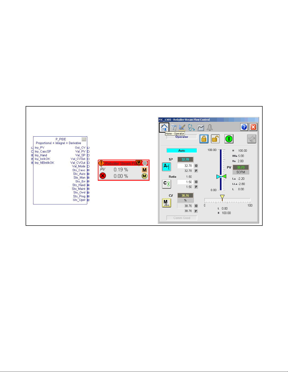
The P_PIDE (Proportional + Integral + Derivative Enhanced) Add-On
Instruction provides the functionality of the Studio 5000 Logix Designer® PIDE
function block with a user experience consistent with the rest of the Rockwell
Automation Library of Process Objects. The global object and following
faceplate are examples of the graphical interface tools for this Add-On
Instruction.
Faceplate
Global Object
Rockwell Automation Publication SYSLIB-RM045D-EN-P - February 2017 7
Page 8
Proportional + Integral + Derivative Enhanced (P_PIDE)
Guidelines
Functional Description
Use this instruction when you plan to use the PIDE for loop control and provide
visualization to the operator.
The primary operations of the P_PIDE Add-On Instructions and its faceplate
include the following:
• All functions of the PIDE built-in instruction for PID loop control
• Process Library alarm objects for deviation alarms, and additional alarm
status information and functionality, including limits, deadbands, and
severities
• Additional context for display, including a description, label, tag, and
engineering units
• P_Mode (mode) object for ownership
• Links for the P_Intlk (interlocks) instruction for interlocking
• Power-up Setpoint, Output, and Loop mode settings
Autotune
You must have a license to edit the autotune tag entry field on the PIDE
instruction. Do these steps to enable the functionality.
1. Open the Logic routine of the ‘P_PIDE_only’ Add-On Instruction.
2. Edit the function block diagram to set the autotune tag to 'Ref_Autotune'.
3. Save your changes and download to your controller.
Once this change has been made, the outer P_PIDE instruction automatically
checks on powerup for response from the Autotune function and automatically
enables the Autotune button on the faceplate. This is a supported
end-user/solution-provider enhancement that does not void tech support.
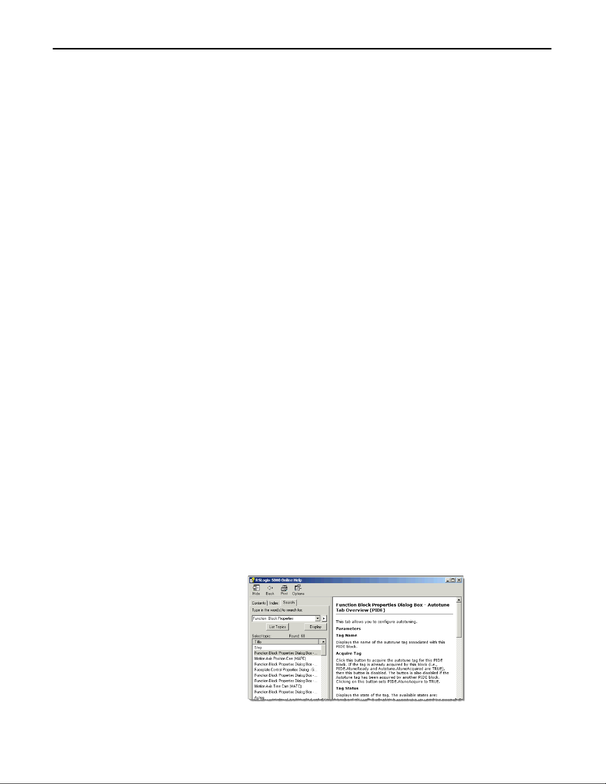
For information on how to use the Autotune function, refer to the following
Logix Designer online help topics:
• Function Block Properties Dialog Box – Autotune Tab Overview (PIDE)
• PIDE Autotune Dialog Box Overview
8 Rockwell Automation Publication SYSLIB-RM045D-EN-P - February 2017
Page 9

Proportional + Integral + Derivative Enhanced (P_PIDE)
Required Files
Add-On Instructions are reusable code objects that contain encapsulated logic
that can streamline implementing your system. This lets you create your own
instruction set for programming logic as a supplement to the instruction set
provided natively in the ControlLogix® firmware. An Add-On Instruction is
defined once in each controller project, and can be instantiated multiple times in
your application code as needed.
Controller File
The P_PIDE_3_5-00_AOI.L5X Add-On Instruction must be imported into
the controller project to be used in the controller configuration. The service
release number (boldfaced) can change as service revisions are created.
Visualization Files
This Add-On Instruction has associated visualization files that provide a
common user interface. These files can be downloaded from the Product
Compatibility and Download Center at
http://www.rockwellautomation.com/rockwellautomation/support/pcdc.page.
IMPORTANT
The visualization file dependencies require Process Library content imports to
occur in a specific order as reflected in the following tables:
• Images
• Global Objects
• Standard Displays
• HMI Tags
• Macros
Images are external graphic files that can be used in displays. They must be
imported for FactoryTalk View to make use of them.
When PNG files are imported, they are renamed by FactoryTalk View with
a .bmp file extension, but retain a .png format.
Table 2 - Visualization Files: Images (.png)
FactoryTalk View SE Software FactoryTalk View ME Software Description
All .png files in the images folder All .png files in the images folder These are the common icons used in the global objects and
standard displays for all Process Objects.
The Global Object files (.ggfx file type) in the following table are Process Library
display elements that are created once and referenced multiple times on multiple
displays in an application. When changes are made to a Global Object, all
instances in the application are automatically updated.
Table 3 - Visualization Files: Global Objects (.ggfx)
FactoryTalk View SE Software FactoryTalk View ME Software Description
(RA-BAS) Common Faceplate Objects (RA-BAS-ME) Common Faceplate Objects Global objects used on process object faceplates.
Rockwell Automation Publication SYSLIB-RM045D-EN-P - February 2017 9
Page 10

Proportional + Integral + Derivative Enhanced (P_PIDE)
Table 3 - Visualization Files: Global Objects (.ggfx)
FactoryTalk View SE Software FactoryTalk View ME Software Description
(RA-BAS) P_PID Graphics Library (RA-BAS-ME) P_PID Graphics Library PID global object device symbols used to build
(RA-BAS) Process Alarm Objects (RA-BAS-ME) Process Alarm Objects Global objects used for managing alarms on process
(RA-BAS) Process Diagnostic Objects (RA-BAS-ME) Process Diagnostic Objects Diagnostic global objects used on process object
(RA-BAS) Process Faceplate Analog Objects (RA-BAS-ME) Process Faceplate Analog Objects Analog global objects used on process object faceplates.
(RA-BAS) Process Help Objects (RA-BAS-ME) Process Help Objects Global objects used for all process objects help displays.
(RA-BAS) Process Interlock Objects (RA-BAS-ME) Process Interlock Objects Global objects used for managing interlocks and
(RA-BAS) Process Mode Objects (RA-BAS-ME) Process Mode Objects Global objects used for managing modes on process
(RA-BAS) BuiltIn Faceplate Objects (RA-BAS-ME) BuiltIn Faceplate Objects Optional
(RA-BAS) BuiltIn Help Objects (RA-BAS-ME) BuiltIn Help Objects Optiional
process graphics.
object faceplates.
faceplates.
permissives on process object faceplates.
object faceplates.
Global objects for built-in instruction faceplates.
Global objects for built-in instruction Help displays.
The Standard Display files (.gfx file type) in the following table are the Process
Library displays that you see at runtime.
Table 4 - Visualization Files: Standard Displays (.gfx)
FactoryTalk View SE Software FactoryTalk View ME Software Description
(RA-BAS) Common-AnalogEdit N/A Faceplate used for analog input data entry. The FactoryTalk
(RA-BAS) P_Alarm-Faceplate (RA-BAS-ME) P_Alarm-Faceplate The faceplate that is used for managing alarms for
(RA-BAS) P_Alarm-Help (RA-BAS-ME) P_Alarm-Help Alarm Help information that is accessed from the
(RA-BAS) P_Gate-Faceplate (RA-BAS-ME) P_Gate-Faceplate The gate faceplate display used for the object.
(RA-BAS) P_Mode-Config (RA-BAS-ME) P_Mode-Config The Configuration Display used to configure the
(RA-BAS) P_Mode-Help (RA-BAS-ME) P_Mode-Help Mode Help information that is accessed from the
(RA-BAS) P_PIDE-Faceplate (RA-BAS-ME) P_PIDE-Faceplate The faceplate that is used for the object
(RA-BAS) P_PIDE-Quick (RA-BAS-ME) P_PIDE-Quick The Quick display that is used for the object
(RA-BAS) Process PID Family-Help (RA-BAS-ME) Process PID Family-Help The Help display for PID objects
(RA-BAS) Built-In Autotune-Faceplate (RA-BAS-ME) Built-In Autotune-Faceplate Optional
(RA-BAS) P_Intlk-Faceplate (RA-BAS-ME) P_Intlk-Faceplate Optional
View ME faceplates use the native analog input data entry
so no file is required.
the object.
P_AIarm faceplate.
P_Mode object.
Help faceplate.
The Autotune faceplate display that is used for the object
Use this file if the object has an associated Autotune object
and you enable navigation to the Autotune faceplate from
the object faceplate.
The interlock faceplate used for the object.
Use this file if your Discrete Output has an associated
P_Intlk object and you enable navigation to its faceplate
from the Discrete Output faceplate.
10 Rockwell Automation Publication SYSLIB-RM045D-EN-P - February 2017
Page 11

Proportional + Integral + Derivative Enhanced (P_PIDE)
Table 4 - Visualization Files: Standard Displays (.gfx)
FactoryTalk View SE Software FactoryTalk View ME Software Description
(RA-BAS) P_Perm-Faceplate (RA-BAS-ME) P_Perm-Faceplate Optional
Permissive faceplate that is used for the object
Use this file if your object has an associated P_Perm object
and you enable navigation to the P_Perm faceplate from
the object faceplate.
(RA-BAS) Process Interlock Family-Help (RA-BAS-ME) Process Interlock Family-Help Optional
Interlock/permissives help display that is used for
the object
Use this file if you use the P_Intlk or P_Perm faceplate.
HMI Tags are created in a FactoryTalk View ME application to support tab
switching on Process Library faceplates. The HMI tags may be imported via the
comma-separated values file (.csv file type) in the following table.
Table 5 - Visualization Files: HMI Tags (.csv)
FactoryTalk View SE Software FactoryTalk View ME Software Description
N/A FTVME_PlantPAxLib_Tags_3_5_xx.csv
where xx = the service release number.
These tags must be imported into the
FactoryTalk View ME project to support switching tabs on
any Process Object faceplate.
Controller Code
This section describes the parameter references for this Add-On Instruction.
Proportional + Integral + Derivative Enhanced Input Structure
Input parameters include the following:
• Input data elements (Inp_) are typically used to connect field inputs from
I/O modules or signals from other objects.
• Configuration data elements (Cfg_) are used to set configurable
capabilities and features of the instruction.
• Commands (PCmd_, OCmd_, MCmd_) are used by program logic,
operators, and maintenance personnel to request instruction actions.
• Settings (PSet_, OSet_, MSet_) are used by program logic, operators, and
maintenance personnel to establish runtime setpoints, thresholds, and so
forth. A Setting (without a leading P, O, or M) establishes runtime settings
regardless of role or mode.
Rockwell Automation Publication SYSLIB-RM045D-EN-P - February 2017 11
Page 12

Proportional + Integral + Derivative Enhanced (P_PIDE)
Table 7 - P_PIDE Input Parameters
Input Parameter Data
Type
EnableIn BOOL 1 Ladder Diagram:
Inp_PV REAL Wrk_PIDE.PV 0.0 Input signal Process Variable (PV) from sensor (PV engineering units).
Inp_CascSP REAL Wrk_PIDE.SPCascade 0.0 Setpoint in cascade, independent PV in Ratio (PV engineering units).
Inp_FF REAL Wrk_PIDE.FF 0.0 FeedForward term (Controlled Variable (CV)%).
Inp_FFPrev REAL Wrk_PIDE.FFPrevious 0.0 FeedForward feedback from downstream block (CV%).
Inp_CVInitVal REAL Wrk_PIDE.CVInitValue 0.0 Value to initialize the CV to when requested (CV engineering units).
Inp_CVPrev REAL Wrk_PIDE.CVPrevious 0.0 CV feedback from downstream block (CV%).
Inp_PVSrcQ SINT 0 Source and Quality of Inp_PV (enumeration)
Inp_OvrdCmd SINT 0 Override Loop mode command:
Inp_OvrdRatio REAL 1.0 Ratio to use in Override mode (unitless).
Inp_OvrdSP REAL 0.0 Setpoint (SP) to use in Override mode (PV engineering units).
Inp_OvrdCV REAL 0.0 CV to use in Override mode (CV%).
Inp_HandFdbk REAL Wrk_PIDE.HandFB 0.0 CV feedback used in Hand mode (CV%).
Inp_PVBad BOOL Wrk_PIDE.PVFault 0 Bad signal quality/communication status for inputs (1 = Bad, 0 = OK). If PV is
Inp_PVUncertain BOOL 0 Uncertain quality for inputs (1 = Uncertain, 0 = OK). This is optional status for
Inp_CVIOFault BOOL Wrk_PIDE.CVFault 0 1 = CV I/O communication status bad
Inp_UseFFPrev BOOL Wrk_PIDE.FFSetPrevious 0 1 = Use Inp_FFPrev as previous FF value
Inp_UseCVInitVal BOOL Wrk_PIDE.CVInitReq 0 1 = Initialize CV to Inp_CVInitValue
Inp_UseCVPrev BOOL Wrk_PIDE.CVSetPrevious 0 1 = Use Inp_CVPrev as previous CV value
Inp_WindupHi BOOL Wrk_PIDE.WindupHIn 0 Windup high signal
Inp_WindupLo BOOL Wrk_PIDE.WindupLIn 0 Windup low signal
Inp_Ovrd BOOL Mode.Inp_Ovrd 0 1 = Acquire Override (higher priority program logic) mode
Inp_Hand BOOL Mode.Inp_Hand 0 1 = Acquire Hand (hard-wired local) mode
Inp_HandFdbkBad BOOL Wrk_PIDE.HandFBFault 0 1 = Inp_HandFdbk input quality or I/O communication status bad
Alias For Default Description
If the rung-in condition is true, the instruction’s Logic routine executes. If the
rung-in condition is false, the instruction’s EnableInFalse routine executes.
Function Block Diagram:
If true, or not connected, the instruction’s Logic routine executes. If the
parameter is exposed as a pin and wired, and the pin is false, the instruction’s
EnableInFalse routine executes.
Structured Text:
No effect. The instruction’s Logic routine executes.
0 = None
1 = Manual
2 = Automatic
3 = Cascade
read from an analog input, then this is normally read from the analog input
channel fault status.
the input that can be used to drive the status of the output (Sts_PVUncertain).
0 = OK
0 = Use last scan value
0 = Use last scan value
1 = Regulator does not increase the output
1 = Regulator does not decrease the output
0 = Release Override mode
0 = Release Hand mode
0 = OK
12 Rockwell Automation Publication SYSLIB-RM045D-EN-P - February 2017
Page 13

Table 7 - P_PIDE Input Parameters
Proportional + Integral + Derivative Enhanced (P_PIDE)
Input Parameter Data
Type
Inp_IntlkOK BOOL 1 1 = Interlocks and non-bypassable Interlocks OK, analog output can be set.
Inp_NBIntlkOK
Inp_HiHiDevGate BOOL HiHiDevGate.Inp_Gate 1 High-High deviation status gate:
Inp_HiDevGate HiDevGate.Inp_Gate High deviation status gate:
Inp_LoDevGate LoDevGate.Inp_Gate Low deviation status gate:
Inp_LoLoDevGate LoLoDevGate.Inp_Gate Low-Low deviation status gate:
Inp_Reset BOOL 0 Input parameter used to programmatically reset alarms. When set to 1, all
Cfg_HasRatio BOOL Wrk_PIDE.UseRatio 0 1 = Cascade Loop mode uses ratio
Cfg_HasCasc BOOL Wrk_PIDE.AllowCasRat 0 1 = Enable the loop to be placed into Cascade/ratio mode
Cfg_PVTrack BOOL Wrk_PIDE.PVTracking 1 1 = SP tracks PV in manual
Cfg_CtrlAction BOOL Wrk_PIDE.ControlAction 0 1 = Direct acting (E = PV-SP)
Cfg_Depend BOOL Wrk_PIDE.DependIndepend 1 1 = Dependent gains equation
Cfg_DerivSmooth BOOL Wrk_PIDE.DSmoothing 0 1 = Use derivative smoothing
Cfg_ZCOff BOOL Wrk_PIDE.ZCOff 0 1 = Need not cross zero error to be in deadband
Cfg_LimitManCV BOOL Wrk_PIDE.CVManLimiting 0 1 = CV limits enforced in manual
Cfg_InitToMan BOOL Wrk_PIDE.ManualAfterInit 0 1 = Go to Manual Loop mode when a CV initialization request is seen
Cfg_PropSPAct BOOL Wrk_PIDE.PVEProportional 0 Proportional action on SP change:
Cfg_DerivSPAct BOOL Wrk_PIDE.PVEDerivative 1 Derivative action on SP change:
Cfg_PwrupLM SINT 0 Powerup Loop mode:
Cfg_SetTrack BOOL 1 This parameter is used to set up bumpless behavior of setting parameters
Cfg_SetTrackOvrdHand BOOL 0 1 = Program/Operator settings track Override/Hand inputs (CV, SP, Ratio)
Alias For Default Description
1 = Enabled.
1 = Enabled
1 = Enabled
1 = Enabled
alarms requiring reset are reset.
0 = Cascade Loop mode does not use ratio
0 = No PV tracking
0 = Reverse acting (E = SP-PV)
0 = Independent gains
0 = Must cross zero error
0 = No CV limiting in manual
1 = None (PV only)
0 = Full (loop error)
1 = None (PV only)
0 = Full (loop error)
0 = No change (last)
1 = Manual (with CV)
2 = Automatic (with SP)
3 = Cascade/Ratio
when switching modes. When this parameter is 1, in Program mode the
operator settings track the program settings; in Operator mode the program
settings track the operator settings; and the simulation inputs match the
output values (transitions are bumpless).
When this parameter is 0, the operator settings and program settings are not
modified by this instruction. In this case, when the mode is changed, the
effective value of the setting can change depending on the program-set and
operator-set values.
Rockwell Automation Publication SYSLIB-RM045D-EN-P - February 2017 13
Page 14

Proportional + Integral + Derivative Enhanced (P_PIDE)
Table 7 - P_PIDE Input Parameters
Input Parameter Data
Type
Cfg_HasIntlkObj BOOL 0 1 = Tells HMI an interlock object (for example, P_Intlk) is used for Inp_IntlkOK
Cfg_HasCascSPNav BOOL 0 1 = Tells HMI to enable navigation to a connected cascade SP object
Cfg_HasPVNav BOOL 0 1 = Tells HMI to enable navigation to a connected PV object
Cfg_HasCVNav BOOL 0 1 = Tells HMI to enable navigation to a connected CV object
Cfg_OvrdIntlk BOOL 0 1 = Override ignores bypassable interlock
Cfg_PCmdClear BOOL Mode.Cfg_PCmdClear 1 When this parameter is 1, program commands are cleared once they are acted
Cfg_ProgDefault BOOL Mode.Cfg_ProgDefault 0 This parameter defines the default mode. When this parameter is 1, the mode
Cfg_HasHiHiDevAlm BOOL HiHiDev.Cfg_Exists 0 These parameters determine whether the corresponding alarm exists and is
Cfg_HasHiDevAlm HiDev.Cfg_Exists
Cfg_HasLoDevAlm LoDev.Cfg_Exists
Cfg_HasLoLoDevAlm LoLoDev.Cfg_Exists
Cfg_HasIntlkTripAlm IntlkTrip.Cfg_Exists
Cfg_HasFailAlm Fail.Cfg_Exists
Cfg_HiHiDevResetReqd BOOL HiHiDev.Cfg_ResetReqd 0 These parameters determine whether a reset is required to clear the alarm
Cfg_HiDevResetReqd HiDev.Cfg_ResetReqd
Cfg_LoDevResetReqd LoDev.Cfg_ResetReqd
Cfg_LoLoDevResetReqd LoLoDev.Cfg_ResetReqd
Cfg_IntlkTripResetReqd IntlkTrip.Cfg_ResetReqd
Cfg_FailResetReqd Fail.Cfg_ResetReqd
Cfg_HiHiDevAckReqd BOOL HiHiDev.Cfg_AckReqd 1 These parameters determine whether an acknowledgement is required for an
Cfg_HiDevAckReqd HiDev.Cfg_AckReqd
Cfg_LoDevAckReqd LoDev.Cfg_AckReqd
Cfg_LoLoDevAckReqd LoLoDev.Cfg_AckReqd
Cfg_IntlkTripAckReqd IntlkTrip.Cfg_AckReqd
Cfg_FailAckReqd Fail.Cfg_AckReqd
Alias For Default Description
and navigation to the interlock object’s faceplate is enabled
IMPORTANT: The name of the Interlock object in the controller must be this
object's name with the suffix ‘_Intlk’. For example, if your P_PIDE object has
the name ’PIDE123’, then its Interlock object must be named ‘PIDE123_Intlk’.
0 = Always use interlock
upon. When set to 0, program commands remain set until cleared by the
application program logic.
IMPORTANT: Clearing this parameter online can cause unintended program
command execution.
defaults to Program if no mode is being requested. When this parameter is 0,
the mode defaults to Operator if no mode is being requested.
IMPORTANT: Changing this parameter online can cause unintended mode
changes.
checked or if the alarm does not exist and is not used. When these parameters
are 1, the corresponding alarm exists.
status. When these parameters are 1, the alarm is latched ON when the alarm
occurs. After the alarm condition returns to normal, a reset is required to clear
the alarm status (for example, OCmd_Reset, Inp_Reset, or
HiHiDev.OCmd_Reset are required to clear Alm_HiHiDev alarm after the alarm
is set and the value returns to normal). When these parameters are 0, no reset
is required and the alarm status is cleared when the alarm condition returns to
normal.
IMPORTANT: If the reset clears the alarm, it also acknowledges the alarm.
alarm. When these parameters are 1, the acknowledge (ack) bit is cleared
when the alarm occurs. An acknowledge command (for example,
PCmd_FailAck or Fail.OCmd_Ack) is required to acknowledge the alarm. When
set to 0, the Acknowledge bit is set when an alarm occurs indicating an
acknowledged alarm and no acknowledge command is required.
14 Rockwell Automation Publication SYSLIB-RM045D-EN-P - February 2017
Page 15
Table 7 - P_PIDE Input Parameters
Proportional + Integral + Derivative Enhanced (P_PIDE)
Input Parameter Data
Type
Cfg_HiHiDevSeverity INT HiHiDev.Cfg_Severity 750 These parameters determine the severity of each alarm. This drives the color
Cfg_HiDevSeverity HiDev.Cfg_Severity 500
Cfg_LoDevSeverity LoDev.Cfg_Severity 500
Cfg_LoLoDevSeverity LoLoDev.Cfg_Severity 750
Cfg_IntlkTripSeverity IntlkTrip.Cfg_Severity 500
Cfg_FailSeverity Fail.Cfg_Severity 1000
Cfg_MinRatio REAL Wrk_PIDE.RatioLLimit 1.0 Minimum and maximum allowed ratio (unitless).
Cfg_MaxRatio Wrk_PIDE.RatioHLimit 1.0
Cfg_MinSP REAL Wrk_PIDE.SPLLimit 0.0 Minimum allowed setpoint (SP) value (PV engineering units).
Cfg_MaxSP REAL Wrk_PIDE.SPHLimit 100.0 Maximum allowed setpoint (SP) value (PV engineering units).
Cfg_PVEUMin REAL Wrk_PIDE.PVEUMin 0.0 PV engineering units Minimum value (PV engineering units).
Cfg_PVEUMax REAL Wrk_PIDE.PVEUMax 100.0 PV (Output) maximum for scaling to engineering units.
Cfg_CVEUMin REAL Wrk_PIDE.CVEUMin 0.0 CV engineering units minimum value (CV engineering units).
Cfg_CVEUMax REAL Wrk_PIDE.CVEUMax 100.0 CV engineering units maximum value (CV engineering units).
Cfg_CVRoCLim REAL Wrk_PIDE.CVROCLimit 0.0 CV rate of change limit (CV%/s), zero means do not limit.
Cfg_PGain REAL Wrk_PIDE.PGain 0.0 Proportional (independent) or loop (dependent) gain (unitless).
Cfg_IGain REAL Wrk_PIDE.IGain Integral gain (1/min independent or min/repeat dependent).
Cfg_DGain REAL Wrk_PIDE.DGain Derivative gain (min).
Cfg_ZCDB REAL Wrk_PIDE.ZCDeadband 0.0 Normal zero crossing deadband (PV engineering units).
Cfg_MinCV REAL Wrk_PIDE.CVLLimit 0.0 Minimum or maximum allowed controlled variable (CV) value (CV%).
Cfg_MaxCV REAL Wrk_PIDE.CVHLimit 100.0
Cfg_MaxInactiveCV REAL 0.0 When Val_CV is greater than this value (CV%) set Sts_Active (for HMI).
Cfg_IntlkCV REAL Wrk_PIDE.CVOverride 0.0 CV to use when interlocks not OK (CV%).
Cfg_DevDB REAL Wrk_PIDE.DevDeadband 0.0 Deviation alarm deadband (PV engineering units).
Cfg_PwrupSP REAL 0.0 Loop SP on powerup, used if Cfg_PwrupLM = 1 (manual) or 2 (automatic).
Cfg_PwrupCV REAL 0.0 Loop CV (CV %) on powerup, used if Cfg_PwrupLM <> 0 (none).
Cfg_HiHiDevOnDly DINT HiHiDevGate.Cfg_OnDly 0 These parameters determine the minimum time (in seconds) the loop
Cfg_HiDevOnDly HiDevGate.Cfg_OnDly
Cfg_LoDevOnDly LoDevGate.Cfg_OnDly
Cfg_LoLoDevOnDly LoLoDevGate.Cfg_OnDly
Cfg_HiHiDevOffDly DINT HiHiDevGate.Cfg_OffDly 0 These parameters determine the amount of time (in seconds) the loop
Cfg_HiDevOffDly HiDevGate.Cfg_OffDly
Cfg_LoDevOffDly LoDevGate.Cfg_OffDly
Cfg_LoLoDevOffDly LoLoDevGate.Cfg_OffDly
Alias For Default Description
and symbol that are used to indicate alarm status on the faceplate and global
object.
The following are valid values:
1…250 = Low
251…500 = Medium
501…750 = High
751…1000 = Urgent
IMPORTANT: For FactoryTalk View software version 7.0, these severity
parameters drive only the indication on the global object and faceplate. The
FactoryTalk Alarms and Events definition of severity drives the color and
symbol that is used on the alarm banner and alarm summary as well as the
value returned by FactoryTalk Alarms and Events display commands.
TIP: The P_PIDE instruction supports reverse CV EU scaling, Cfg_CVEUMax can
be less than (but not equal to) Cfg_CVEUMin.
deviation must remain beyond the status threshold for the status to be set. Ondelay times are used to avoid unnecessary alarms when the deviation
momentarily overshoots its threshold (for example, Val_HiHiDevLim).
deviation must stay within each status threshold to clear the status. Off delay
times are used to reduce chattering alarms.
EXAMPLE: If Cfg_HiDevOffDly is 5 seconds, the loop deviation must be below
the status limit (Val_HiHiDevLim) minus deadband (Cfg_DevDB) for 5 seconds
before the status is returned to normal.
Rockwell Automation Publication SYSLIB-RM045D-EN-P - February 2017 15
Page 16

Proportional + Integral + Derivative Enhanced (P_PIDE)
Table 7 - P_PIDE Input Parameters
Input Parameter Data
Type
Cfg_HiHiDevGateDly DINT HiHiDevGate.Cfg_GateDly 0 These parameters determine the amount of time (in seconds) the gate input
Cfg_HiDevGateDly HiDevGate.Cfg_GateDly
Cfg_LoDevGateDly LoDevGate.Cfg_GateDly
Cfg_LoLoDevGateDly LoLoDevGate.Cfg_GateDly
PSet_Ratio REAL 1.0 Program setting for ratio (loop cascade and ratio enabled) (unitless).
PSet_SP 0.0 Program setting for setpoint (loop auto) (PV engineering units).
PSet_CV 0.0 Program setting for controlled variable (loop manual) (CV%).
PSet_HiHiDevLim REAL 3.40282347e+038 Program setting for High-High, High, Low, or Low-Low deviation status
PSet_HiDevLim
PSet_LoDevLim -3.40282347e+038
PSet_LoLoDevLim
PSet_Owner DINT 0 Program owner request ID (non-zero) or release (zero).
OSet_Ratio REAL 1.0 Operator setting for ratio (loop cascade and ratio enabled) (unitless).
OSet_SP 0.0 Operator setting for setpoint (loop auto) (PV engineering units).
OSet_CV 0.0 Operator setting for controlled variable (loop manual) (CV%).
OSet_HiHiDevLim 3.40282347e+038 Operator settings for High-High, High, Low, or Low-Low deviation status
OSet_HiDevLim
OSet_LoDevLim -3.40282347e+038
OSet_LoLoDevLim
PCmd_Casc BOOL 0 When Cfg_PCmdClear is 1:
PCmd_Auto
PCmd_Man
PCmd_Acq BOOL Mode.PCmd_Acq 0 When Cfg_PCmdClear is 1:
PCmd_Rel Mode.PCmd_Rel
PCmd_Lock BOOL Mode.PCmd_Lock 0 When Cfg_PCmdClear is 1:
PCmd_Unlock Mode.PCmd_Unlock
PCmd_Reset BOOL 0 • Set PCmd_Reset to 1 to reset all alarms requiring reset
Alias For Default Description
must be turned on for threshold detection to be enabled. On delays and off
delays are applied after the gate delay is complete.
threshold (PV engineering units).
threshold (PV engineering units).
• Set PCmd_Casc to 1 to select Cascade/Ratio Loop mode
• Set PCmd_Auto to 1 to select Automatic Loop mode
• Set PCmd_Man to 1 to select Manual Loop mode
• These parameters reset automatically
When Cfg_PCmdClear is 0:
• Set PCmd_Casc to 1 to select Cascade/Ratio Loop mode
• Set PCmd_Auto to 1 to select Automatic Loop mode
• Set PCmd_Auto and PCmd_Casc to 0 to select Manual Loop mode
• PCmd_Man is not used
• These parameters do not reset automatically
• Set PCmd_Acq to 1 to Acquire
• Set PCmd_Rel to 1 to Release
• These parameters reset automatically
When Cfg_PCmdClear is 0:
• Set PCmd_Acq to 1 to Acquire
• Set PCmd_Acq to 0 to Release
• PCmd_Rel is not used
• These parameters do not reset automatically
• Set PCmd_Lock to 1 to Lock
• Set PCmd_Unlock to 1 to Unlock
• These parameters reset automatically
When Cfg_PCmdClear is 0:
• Set PCmd_Lock to 1 to Lock
• Set PCmd_Lock to 0 to Unlock
• PCmd_Unlock is not used
• These parameters do not reset automatically
• This parameter is always reset automatically
16 Rockwell Automation Publication SYSLIB-RM045D-EN-P - February 2017
Page 17

Table 7 - P_PIDE Input Parameters
Proportional + Integral + Derivative Enhanced (P_PIDE)
Input Parameter Data
Type
PCmd_HiHiDevAck BOOL HiHiDev.PCmd_Ack 0 • Set PCmd_<Alarm>Ack to 1 to Acknowledge alarm
PCmd_HiDevAck HiDev.PCmd_Ack
PCmd_LoDevAck LoDev.PCmd_Ack
PCmd_LoLoDevAck LoLoDev.PCmd_Ack
PCmd_IntlkTripAck IntlkTrip.PCmd_Ack
PCmd_FailAck Fail.PCmd_Ack
PCmd_HiHiDevSuppress BOOL HiHiDev.PCmd_Suppress 0 When Cfg_PCmdClear is 1:
PCmd_HiDevSuppress HiDev.PCmd_Suppress
PCmd_LoDevSuppress LoDev.PCmd_Suppress
PCmd_LoLoDevSuppress LoLoDev.PCmd_Suppress
PCmd_IntlkTripSuppress IntlkTrip.PCmd_Suppress
PCmd_FailSuppress Fail.PCmd_Suppress
PCmd_HiHiDevUnsuppress BOOL HiHiDev.PCmd_Unsuppress 0
PCmd_HiDevUnsuppress HiDev.PCmd_Unsuppress
PCmd_LoDevUnsuppress LoDev.PCmd_Unsuppress
PCmd_LoLoDevUnsuppress LoLoDev.PCmd_Unsuppress
PCmd_IntlkTripUnsuppress IntlkTrip.PCmd_Unsuppress
PCmd_FailUnsuppress Fail.PCmd_Unsuppress
PCmd_HiHiDevUnshelve BOOL HiHiDev.PCmd_Unshelve 0 • Set PCmd_<Alarm>Unshelve to 1 to Unshelve alarm
PCmd_HiDevUnshelve HiDev.PCmd_Unshelve
PCmd_LoDevUnshelve LoDev.PCmd_Unshelve
PCmd_LoLoDevUnshelve LoLoDev.PCmd_Unshelve
PCmd_IntlkTripUnshelve IntlkTrip.PCmd_Unshelve
PCmd_FailUnshelve Fail.PCmd_Unshelve
OCmd_Casc BOOL 0 Operator commands to select Cascade/ratio (Casc), Automatic (Auto), or
OCmd_Auto BOOL 0
OCmd_Man BOOL 0
OCmd_Bypass BOOL 0 Operator command to bypass the bypassable interlocks.
OCmd_Check BOOL 0 Operator command to check (not bypass) all interlocks.
MCmd_Disable BOOL 0 Maintenance command to disable or enable PID loop.
MCmd_Enable
MCmd_Acq BOOL Mode.MCmd_Acq 0 Maintenance command to acquire ownership (operator/program/override to
MCmd_Rel BOOL Mode.MCmd_Rel 0 Maintenance command to release ownership (maintenance to operator/
OCmd_AcqLock BOOL Mode.OCmd_AcqLock 0 Operator command to acquire (program to operator)/lock ownership.
OCmd_Unlock BOOL Mode.OCmd_UnlockRel 0 Operator command to unlock/release (operator to program) ownership.
OCmd_Reset BOOL 0 Operator command to reset all alarms requiring reset.
OCmd_ResetAckAll BOOL 0 Operator command to reset all alarms and latched shed conditions.
Alias For Default Description
• The parameter is reset automatically
• Set PCmd_<Alarm>Suppress to 1 to suppress alarm
• Set PCmd_<Alarm>Unsuppress to 1 to unsuppress alarm
• These parameters reset automatically
When Cfg_PCmdClear is 0:
• Set PCmd_<Alarm>Suppress to 1 to suppress alarm
• Set PCmd_<Alarm>Suppress to 0 to unsuppress alarm
• PCmd_<Alarm>Unsuppress is not used
• These parameters do not reset automatically
• The parameter is reset automatically
Manual (Man) Loop mode.
Maintenance).
program/override).
Rockwell Automation Publication SYSLIB-RM045D-EN-P - February 2017 17
Page 18

Proportional + Integral + Derivative Enhanced (P_PIDE)
Table 8 - P_PIDE Output Parameters
Proportional + Integral + Derivative Enhanced Output Structure
Output parameters include the following:
• Output data elements (Out_) are the primary outputs of the instruction,
typically used by hardware output modules; however, they can be used by
other application logic.
• Value data elements (Val_) are numeric outputs of the instruction for use
by the HMI. Values can also be used by other application logic or software
packages.
• Source and Quality data elements (SrcQ_) are outputs of the instruction
used by the HMI to indicate PV source and quality.
• Status data elements (Sts_) are bit outputs of the instruction for use by the
HMI. Status bits can also be used by other application logic.
• Error data elements (Err_) are outputs of the instruction that indicate a
particular configuration error. If any Err_ bit is set, then the Sts_Err
configuration error summary status is set and the Invalid Configuration
indicator is displayed on the HMI.
• Not Ready data elements (Nrdy_) are bit outputs of the instruction for use
by the HMI for displaying the Device Not Ready indicator. Not Ready bits
can also be used by other application logic.
• Alarm data elements (Alm_) are outputs of the instruction that indicate a
particular alarm has occurred.
• Acknowledge data elements (Ack_) are outputs of the instruction that
indicate the corresponding alarm has been acknowledged.
• Ready data elements (Rdy_) are bit outputs of the instruction used by the
HMI to enable or disable Command buttons and Setting entry fields.
Output Parameter Data Type Alias For Description
EnableOut BOOL Enable output: The EnableOut signal is not manipulated by this instruction. Its output state
Out_CV REAL Wrk_PIDE.CVEU CV to final control element (CV engineering units).
Val_PV REAL Loop PV (PV engineering units).
Val_Ratio REAL Wrk_PIDE.Ratio The current ratio (unitless).
Val_SPSet REAL Value of selected SP (before clamping) (PV engineering units).
Val_SP REAL Wrk_PIDE.SP Value of SP being used (after clamping) (PV engineering units).
Val_E REAL Wrk_PIDE.E Loop error (PV-SP) (PV engineering units).
Val_CVSet REAL Value of CV output (before ramping and clamping (CV%).
Val_CVOut REAL Wrk_PIDE.CV Value of CV output (after ramping and clamping (CV%).
Val_PVPercent REAL Wrk_PIDE.PVPercent Loop PV (percent of span).
Val_SPPercent REAL Wrk_PIDE.SPPercent Loop SP (percent of span).
Val_EPercent REAL Wrk_PIDE.EPercent Loop error (PV-SP) (percent of span).
Val_ActExecT REAL Wrk_PIDE.DeltaT Actual PID algorithm execution time (elapsed time between updates) (seconds).
Val_Init REAL Initialization value for this loop's cascade primary (PV engineering units).
Val_PVEUMin REAL Minimum of PV scaled range (PV engineering units).
always reflects EnableIn input state.
18 Rockwell Automation Publication SYSLIB-RM045D-EN-P - February 2017
Page 19

Proportional + Integral + Derivative Enhanced (P_PIDE)
Table 8 - P_PIDE Output Parameters
Output Parameter Data Type Alias For Description
Val_PVEUMax REAL Maximum of PV scaled range (PV engineering units).
Val_CVEUMin REAL Minimum of CV scaled range (CV engineering units).
Val_CVEUMax REAL Maximum of CV scaled range (CV engineering units).
SrcQ_IO SINT I/O signal source and quality.
SrcQ Final source and quality.
GOOD 0 = I/O live and confirmed good quality
1 = I/O live and assumed good quality
2 = No feedback configured, assumed good quality
TEST 8 = Device simulated
9 = Device loopback simulation
10 = Manually entered value
UNCERTAIN 16 = Live input, off-specification
17 = Value substituted at device/bus
18 = Value substituted by maintenance (Has and not Use)
19 = Shed, using last good value
20 = Shed, using replacement value
BAD 32 = Signal failure (out-of-range, NaN, invalid combination)
33 = I/O channel fault
34 = I/O module fault
35 = Bad I/O configuration (for example, scaling parameters)
Val_Sts SINT Loop status enumeration:
0 = Unknown
1 = Manual
2 = Auto
3 = Cascade
4 = Ratio
33 = Disabled
Val_Fault SINT Loop fault status:
0 = None
22 = Low Deviation
23 = High Deviation
27 = Low-Low Deviation
28 = High-High Deviation
29 = Interlock Trip Shed
32 = FailShed
34 = Configuration Error
Val_State Loop algorithm state:
1 = In deadband
2 = Outside deadband controlling
5 = Ratio clamped
6 = SP clamped
7 = CV clamped
8 = Windup Low
9 = Windup High
13 = Interlocked
14 = Hand
15 = Initializing
Rockwell Automation Publication SYSLIB-RM045D-EN-P - February 2017 19
Page 20

Proportional + Integral + Derivative Enhanced (P_PIDE)
Table 8 - P_PIDE Output Parameters
Output Parameter Data Type Alias For Description
Val_Mode SINT Mode.Val The current mode is shown with status bits and also as an enumeration ‘Val_Mode’ as
Val_Owner DINT Current object owner ID (0 = not owned).
Val_Notify SINT Current alarm level and acknowledgement (enumeration):
Val_HiHiDevLim REAL Wrk_PIDE.DevHHLimit Current High-High, High, Low, Low-Low deviation status threshold (PV engineering units).
Val_HiDevLim Wrk_PIDE.DevHLimit
Val_LoDevLim Wrk.PIDE.DevLLimit
Val_LoLoDevLim Wrk.PIDE.DevLLLimit
Sts_InstrFaults1 DINT 2#0000_0000_0000_0000
_0000_0000_0000_0000
Sts_InstrFaults2 2#0000_0000_0000_0000
_0000_0000_0000_0000
Sts_Casc BOOL Wrk_PIDE.CasRat 1 = Loop mode is cascade/ratio, automatic, or manual.
Sts_Auto Wrk_PIDE.Auto
Sts_Man Wrk_PIDE.Manual
Sts_Initializing BOOL Wrk_PIDE.CVInitializing 1 = CV is initializing because of request from this loop's secondary.
Sts_InitReq BOOL Wrk_PIDE.InitPrimary 1 = CV initialize request to this loop's primary.
Sts_WindupHi BOOL Wrk_PIDE.WindupHOut 1 = This loop winding up High, to Inp_WindupHi of this loop's primary.
Sts_WindupLo BOOL Wrk_PIDE.WindupLOut 1 = This loop winding up Low, to Inp_WindupLo of this loop's primary.
Sts_ZCDBOn BOOL Wrk_PIDE.ZCDeadbandOn Deadband indicator:
Sts_RatioClamped BOOL 1 = Selected ratio (PSet/OSet_Ratio or Inp_OvrdRatio) has been clamped.
Sts_SPBad BOOL Wrk_PIDE.SPOperInv 1 = SP Value is bad (quality) or invalid or Casc SP communication fault.
Sts_SPClamped BOOL 1 = Selected SP is being clamped (for faceplate animation).
Sts_PVBad BOOL Wrk_PIDE.PVFaulted 1 = PV Value, communication, quality, or engineering units limit is bad.
Sts_PVUncertain BOOL 1 = PV Value is uncertain (quality).
Sts_FFBad BOOL Wrk_PIDE.FFInv 1 = Feedforward term value is invalid.
follows:
0 = No mode
1 = Hand
2 = Maintenance
3 = Override
4 = Program (locked)
5 = Operator (locked)
6 = Program (unlocked, Operator is default)
7 = Operator (unlocked, Program is default)
8 = Program (unlocked, Program is default)
9 = Operator (unlocked, Operator is default)
0 = No alarm
1 = Alarm cleared: a reset or acknowledge is required
2 = Low (acknowledged)
3 = Low (unacknowledged)
4 = Medium (acknowledged)
5 = Medium (unacknowledged)
6 = High (acknowledged)
7 = High (unacknowledged)
8 = Urgent (acknowledged)
9 = Urgent (unacknowledged)
These parameters are aliased to parameter DevHHLimit, DevHLimit, DevLLimit, or DevLLLimit
of the contained PIDE built-in instruction.
PIDE Block Status 1 Instruction Fault bits (see PIDE Instruction Help).
PIDE Block Status 2 Instruction Fault bits (see PIDE Instruction Help).
1 = Error is within zero-crossing deadband and CV does not change
20 Rockwell Automation Publication SYSLIB-RM045D-EN-P - February 2017
Page 21

Proportional + Integral + Derivative Enhanced (P_PIDE)
Table 8 - P_PIDE Output Parameters
Output Parameter Data Type Alias For Description
Sts_FFPrevBad BOOL Wrk_PIDE.FFPreviousInv 1 = Inp_FFPrev is <-100.0, >100.0, or not a number (NaN).
Sts_CVBad BOOL Wrk_PIDE.CVFaulted 1 = CV Value is bad (quality) or invalid or there is a CV communication fault.
Sts_CVPrevBad BOOL Wrk_PIDE.CVPreviousInv 1 = Inp_CVPrev is <0.0, >100.0, or not a number (NaN).
Sts_CVInitValBad BOOL 1 = Inp_CVInitVal is <0.0, >100.0, or not a number (NaN).
Sts_HandFdbkBad BOOL Wrk_PIDE.HandFBFaulted 1 = Hand feedback (tieback) value is bad (quality), invalid, or communication fault.
Sts_IntlkCV BOOL 1 = CV value being set by shed to Interlock CV.
Sts_CVClamped BOOL 1 = Selected CV is being clamped (for faceplate animation).
Sts_CVRamping BOOL Wrk_PIDE.CVROCAlarm 1 = CV is ramping toward Val_CVSet
0 = Ramp complete
Sts_Active BOOL 1 = CV is greater than Cfg_MaxInactiveCV, show graphic symbol as ‘active’ (for example.
Sts_Available BOOL 1 = Instruction available for control by automation (Program).
Sts_Bypass BOOL 1 = Bypassable interlocks are bypassed.
Sts_BypActive BOOL 1 = Bypassing active (Bypassed or Maintenance).
Sts_Disabled BOOL 1 = Loop is disabled (held at configured Interlock CV).
Sts_NotRdy BOOL 1 = Loop is not ready to be operated. See detail Not Ready bit for reason.
Nrdy_Disabled BOOL 1 = Loop Not Ready:
Nrdy_CfgErr
Nrdy_Intlk
Nrdy_Init
Nrdy_IOFault
Nrdy_NoMode
Sts_MaintByp BOOL 1 = Loop has a maintenance bypass function active.
Sts_AlmInh BOOL 1 = One or more alarms shelved, disabled, or suppressed.
Sts_Err BOOL 1 = Error in configuration: see detail error bits for reason.
Err_RatioLim BOOL Wrk_PIDE.RatioLimitsInv 1 = Error in configuration: ratio clamping limits invalid.
Err_SPLim BOOL Wrk_PIDE.SPLimitsInv 1 = Error in configuration: setpoint clamping limits invalid.
Err_PVEU BOOL Wrk_PIDE.PVSpanInv 1 = Error in configuration: PV engineering units (EU) maximum/minimum invalid.
Err_CVLim BOOL Wrk_PIDE.CVLimitsInv 1 = Error in configuration: CV clamping limits invalid.
Err_CVEU BOOL Wrk_PIDE.CVEUSpanInv 1 = Error in configuration: CV engineering units (EU) maximum/minimum invalid.
Err_Timer BOOL 1 = Error in configuration: status on-delay or off-delay time invalid.
Err_DB BOOL Wrk_PIDE.ZCDeadbandInv 1 = Error in configuration: zero-crossing deadband invalid.
Err_Alarm BOOL 1 = Error in configuration: alarm severity, minimum on time, or shelf time invalid.
Sts_Hand BOOL Mode.Sts_Hand 1 = Mode is Hand (supersedes Operator, Program, Override, and Maintenance), Maintenance
Sts_Maint Mode.Sts_Maint
Sts_Ovrd Mode.Sts_Ovrd
Sts_Prog Mode.Sts_Prog
Sts_Oper Mode.Sts_Oper
Sts_ProgOperLock BOOL Mode.Sts_ProgOperLock 1 = Program or Operator has requested mode lock.
Sts_NoMode BOOL Mode.Sts_NoMode 1 = No mode selected (instruction scanned false).
valve open).
• Loop disabled by Maintenance
• Configuration error
• Interlock not OK
• Initialized to Manual mode
• I/O Fault (shed requires reset)
• Loop logic disabled/no mode
(supersedes Operator, Program, and Override), Override (supersedes Operator and Program),
Program, or Operator.
Rockwell Automation Publication SYSLIB-RM045D-EN-P - February 2017 21
Page 22

Proportional + Integral + Derivative Enhanced (P_PIDE)
Table 8 - P_PIDE Output Parameters
Output Parameter Data Type Alias For Description
Sts_MAcqRcvd BOOL Mode.Sts_MAcqRcvd 1 = Maintenance Acquire command received this scan.
Sts_HiHiDevCmp BOOL HiHiDevGate.Inp High-High, High, Low, or Low-Low deviation comparison result:
Sts_HiDevCmp HiDevGate.Inp
Sts_LoDevCmp LoDevGate.Inp
Sts_LoLoDevCmp LoLoDevGate.Inp
Sts_HiHiDevGate BOOL HiHiDevGate.Sts_Gate High-High, High, Low, or Low-Low deviation gate delay status:
Sts_HiDevGate HiDevGate.Sts_Gate
Sts_LoDevGate LoDevGate.Sts_Gate
Sts_LoLoDevGate LoLoDevGate.Sts_Gate
Sts_HiHiDev BOOL HiHiDev.Inp 1 = PV deviation is above High-High, above High, below Low, or below Low-Low limit.
Sts_HiDev HiDev.Inp
Sts_LoDev LoDev.Inp
Sts_LoLoDev LoLoDev.Inp
Sts_IntlkTrip IntlkTrip.Inp 1 = Interlock NOT OK caused loop output to hold or change.
Sts_Fail Fail.Inp 1 = Loop Failure: PV Bad, SP Bad or CV Communication failure or bad.
Alm_HiHiDev BOOL HiHiDev.Alm 1 = Loop High-High, High, Low, or Low-Low deviation alarm.
Alm_HiDev HiDev.Alm
Alm_LoDev LoDev.Alm
Alm_LoLoDev LoLoDev.Alm
Alm_IntlkTrip IntlkTrip.Alm 1 = Interlock trip alarm.
Alm_Fail Fail.Alm 1 = Loop failure alarm: PV Bad, SP Bad or CV Communication failure or bad.
Ack_HiHiDev BOOL HiHiDev.Ack 1 = High-High, High, Low, or Low-Low deviation, Interlock Trip, or Loop Failure alarm has
Ack_HiDev HiDev.Ack
Ack_LoDev LoDev.Ack
Ack_LoLoDev LoLoDev.Ack
Ack_IntlkTrip IntlkTrip.Ack
Ack_Fail Fail.Ack
Sts_HiHiDevDisabled BOOL HiHiDev.Disabled 1 = High-High, High, Low, or Low-Low deviation, Interlock Trip, or Loop Failure alarm has
Sts_HiDevDisabled HiDev.Disabled
Sts_LoDevDisabled LoDev.Disabled
Sts_LoLoDevDisabled LoLoDev.Disabled
Sts_IntlkTripDisabled IntlkTrip.Disabled
Sts_FailDisabled Fail.Disabled
Sts_HiHiDevShelved BOOL HiHiDev.Shelved 1 = High-High deviation, High deviation, Low deviation, Low-Low deviation, Interlock Trip, or
Sts_HiDevShelved HiDev.Shelved
Sts_LoDevShelved LoDev.Shelved
Sts_LoLoDevShelved LoLoDev.Shelved
Sts_IntlkTripShelved IntlkTrip.Shelved
Sts_FailShelved Fail.Shelved
1 = Deviation beyond limit.
1 = done.
been acknowledged.
been disabled by Maintenance.
Loop Failure alarm has been shelved by Operator.
22 Rockwell Automation Publication SYSLIB-RM045D-EN-P - February 2017
Page 23

Proportional + Integral + Derivative Enhanced (P_PIDE)
Table 8 - P_PIDE Output Parameters
Output Parameter Data Type Alias For Description
Sts_HiHiDevSuppressed BOOL HiHiDev.Suppressed 1 = High-High deviation, High deviation, Low deviation, Low-Low deviation, Interlock Trip, or
Sts_HiDevSuppressed HiDev.Suppressed
Sts_LoDevSuppressed LoDev.Suppressed
Sts_LoLoDevSuppressed LoLoDev.Suppressed
Sts_IntlkTripSuppressed IntlkTrip.Suppressed
Sts_FailSuppressed Fail.Suppressed
Rdy_Casc BOOL 1 = Ready to receive operator command: cascade, automatic, manual, bypass, or check
Rdy_Auto
Rdy_Man
Rdy_Bypass
Rdy_Check
Rdy_Disable BOOL 1 = Ready to receive MCmd_Disable (enables HMI button).
Rdy_Enable BOOL 1 = Ready to receive MCmd_Enable (enables HMI button).
Rdy_Reset BOOL 1 = Ready to receive OCmd_Reset (enables HMI button).
Rdy_ResetAckAll BOOL 1 = At least one Alarm or latched Shed condition requires Reset or Acknowledge.
Rdy_Ratio BOOL 1 = Ready to receive OSet_Ratio (enables data entry field).
Rdy_SP BOOL 1 = Ready to receive OSet_SP (enables data entry field).
Rdy_CV BOOL 1 = Ready to receive OSet_CV (enables data entry field).
Rdy_OSet BOOL 1 = Ready to receive other OSets (enables data entry fields).
P_PIDE BOOL Unique parameter name for auto-discovery.
Loop Failure alarm has been suppressed by Program.
(enables HMI button).
Proportional + Integral + Derivative Enhanced Local Configuration Tags
Configuration parameters that are arrayed, string, or structure data types cannot
be configured as parameters for Add-On Instructions. Configuration parameters
of these types appear as local tags to the Add-On Instruction. Local tags can be
configured through the HMI faceplates or in Logix Designer application by
opening the instruction logic of the Add-On Instruction instance and then
opening the Data Monitor on a local tag. These parameters cannot be modified
by using controller logic or Logix Designer application export/import
functionality.
Table 9 - Input Local Configuration Tags
Tag Name Data Type Default Description
Cfg_CascSPNavTag STRING_NavTag ' ' Tag name for destination of Cascade SP navigation button.
IMPORTANT: This tag does not work in FactoryTalk ME software.
Cfg_CVEU STRING_8 '%' CV engineering units displayed on HMI.
Cfg_CVNavTag STRING_NavTag ' ' Tag name for destination of CV navigation button.
IMPORTANT: This tag does not work in FactoryTalk ME software.
Cfg_Desc STRING_40 'PID Control Loop' Description for display on HMI. This string is shown in the title bar of the faceplate.
Rockwell Automation Publication SYSLIB-RM045D-EN-P - February 2017 23
Page 24

Proportional + Integral + Derivative Enhanced (P_PIDE)
Table 9 - Input Local Configuration Tags
Cfg_Label STRING_20 'PID Loop' Label for graphic symbol displayed on HMI. This string appears on the graphic symbol.
Cfg_PVEU STRING_8 '%' PV/setpoint engineering units displayed on HMI.
Cfg_PVNavTag STRING_NavTag ' ' Tag name for destination of PV navigation button.
IMPORTANT: This tag does not work in FactoryTalk ME software.
Cfg_Tag STRING_20 'P_PIDE' Tag name displayed on HMI. This string is shown in the title bar of the faceplate.
Operations
This section describes the primary operations for Add-On Instructions.
Modes
This instruction uses the following standard modes, which are implemented by
using an embedded P_Mode Add-On Instruction.
Table 10 - Modes
Mode Description
Operator Control of the loop is owned by the Operator. Operator Commands (OCmd_) and Operator
Settings (OSet_) from the HMI are accepted.
Program Control of the loop is owned by Program logic. Program Commands (PCmd_) and Program
Settings (PSet_) are accepted.
Override Control of the loop is owned by priority logic, superseding Operator and Program control.
Override Inputs (Inp_OvrdCmd and other Inp_OvrdXxxx values) are accepted. If so configured,
bypassable interlocks are bypassed.
Maintenance Control of the loop is owned by Maintenance. Operator Commands and Settings from the HMI
are accepted. Bypassable interlocks are bypassed.
Hand Control of the final control element is owned by hard-wired logic or other logic outside the
instruction. The instruction CV tracks the hand feedback for bumpless transfer back to one of the
other modes.
No Mode The loop is disabled and has no owner because the EnableIn input is false. The main instruction
Logic routine is not being scanned. See Execution for more information on EnableInFalse
processing.
See Rockwell Automation Library of Process Objects: Common Mode Block
(P_Mode) Reference Manual, publication SYSLIB-RM005, for more
information.
Loop Modes
The P_PIDE Add-On Instruction uses the following Loop modes.
Loop Mode Description
Manual (Man) The P_PIDE controlled variable (CV) output is manipulated directly and the PID algorithm
Automatic (Auto) The P_PIDE setpoint (SP) is manipulated. The PID algorithm uses the difference between
24 Rockwell Automation Publication SYSLIB-RM045D-EN-P - February 2017
is not calculated.
the SP and the process variable (PV) to calculate a CV to bring the PV back to setpoint.
Page 25

Proportional + Integral + Derivative Enhanced (P_PIDE)
Loop Mode Description
Cascade (Casc) The P_PIDE setpoint is provided via the Inp_CascSP input. If ratio control is enabled, this
input is multiplied by the current ratio to determine the loop setpoint. The PID algorithm
uses the difference between the setpoint and the PV to calculate a CV to bring the PV to
setpoint.
Alarms
This instruction uses the following alarms, which are implemented by using
embedded P_Alarm and P_Gate Add-On Instructions.
Alarm Name P_Alarm Name P_Gate Name Description
Fail Fail None Raised when the internal PIDE instruction reports an
High Deviation HiDev HiDevGate Raised when the amount by which the PV exceeds the
High-High
Deviation
HiHiDev HiHiDevGate Raised when the amount by which the PV exceeds the
Instruction Fault. The PIDE instruction reports an
Instruction Fault under any of the following
conditions:
• Process variable (PV) bad quality
• Control variable (CV) bad quality
• Hand feedback bad quality
• Invalid span of PV. PVEUMax -PVEUMin
• Setpoint below low setpoint limit or above high
setpoint limit. The instruction uses the clamped
value for SP
• Limits invalid: SPLoLim < PVEUMin, SPHiLim >
PVEUMax, or SPHiLim < SPLoLim. If SPHiLim <
SPLoLim, the instruction limits the value using
SPLLimit
• Ratio below low ratio limit or above high ratio
limit. The instruction uses the clamped value for
Ratio
• CV < 0 or CV > 100, CV below low CV limit, or CV
above high CV limit when the Loop Mode is
Manual and Manual Limiting is enabled. The
instruction clamps the value for CV
• Interlock CV is < 0 or > 100 and the Interlock CV is
active. The instruction clamps the value for CV
• Invalid CVEU span. The instruction uses a value of
CVEUMax = CVEUMin
• CVLLimit < 0, CVHLimit > 100, or CVHLimit <
CVLLimit. If CVHLimit < CVLLimit, the instruction
limits CV using CVLLimit
• CVRoCLimit < 0. The instruction disables rate of
change limiting
• Feedforward < -100 or > 100. The instruction
clamps the value for Feedforward
• Hand Feedback < 0 or > 100. The instruction
clamps the Hand Feedback value
• Proportional gain < 0. The instruction uses a value
of PGain = 0
• Integral gain < 0. The instruction uses a value of
IGain = 0
• Derivative gain < 0. The instruction uses a value of
DGain = 0
• Zero crossing deadband < 0. The instruction
disables zero crossing deadband
setpoint or reference is above the High Deviation
threshold. The threshold is set by the operator or by
program logic. Deadband, gating, and timing are set
in configuration.
setpoint or reference is above the High-High Deviation
threshold. The threshold is set by the operator or by
program logic. Deadband, gating, and timing are set
in configuration.
Rockwell Automation Publication SYSLIB-RM045D-EN-P - February 2017 25
Page 26

Proportional + Integral + Derivative Enhanced (P_PIDE)
Alarm Name P_Alarm Name P_Gate Name Description
Interlock Trip IntlkTrip None Raised when an interlock ’not OK’ condition causes
Low Deviation LoDev LoDevGate Raised when the amount by which the PV exceeds the
Low-Low
Deviation
LoLoDev LoLoDevGate Raised when the amount by which the PV exceeds the
the output CV to be changed to the configured
Interlock CV value or held at its last value.
If interlocks are not bypassed, a bypassable interlock
or a non-bypassable interlock ’not OK’ condition
initiates an interlock trip. If interlocks are bypassed,
only a non-bypassable interlock ’not OK’ condition
initiates an interlock trip.
setpoint or reference is below the Low Deviation
threshold. (Since the threshold is a negative number,
this is the amount the PV falls below the setpoint or
reference.) The threshold is set by the operator or by
program logic. Deadband, gating, and timing are set
in configuration.
setpoint or reference is below the Low-Low Deviation
threshold. (Since the threshold is a negative number,
this is the amount the PV falls below the setpoint or
reference.) The threshold is set by the operator or by
program logic. Deadband, gating, and timing are set
in configuration.
Parameters of the P_Alarm object can be accessed by using the following
convention: [P_Alarm Name].[P_Alarm Parameter].
For more information, see the following Rockwell Automation Library of Process
Objects publications:
• Common Alarm Block (P_Alarm) Reference Manual,
publication
SYSLIB-RM002
• Condition Gate Delay (P_Gate) Reference Manual,
publication
SYSLIB-RM041
Simulation
The P_PIDE Add-On Instruction does not have Simulation capability.
Execution
The following table explains the handling of instruction execution conditions
Condition Description
EnableIn False (false rung) The instruction Mode is shown as No Mode. The loop status is shown as
Powerup (prescan, first scan) Received commands are cleared. The loop is initialized with the powerup
Postscan (SFC Transition) No SFC postscan logic is provided.
disabled. The loop CV is set to the configured interlock CV value.
Loop mode, CV, and SP.
26 Rockwell Automation Publication SYSLIB-RM045D-EN-P - February 2017
Page 27

Proportional + Integral + Derivative Enhanced (P_PIDE)
See the Logix5000 Controllers Add-On Instructions Programming Manual,
publication
1756-PM010, for more information.
Rockwell Automation Publication SYSLIB-RM045D-EN-P - February 2017 27
Page 28

Proportional + Integral + Derivative Enhanced (P_PIDE)
Programming Example
The following example shows P_PIDE with P_VSD.
The output of the P_PIDE block (Out_CV) is used as the input to the P_VSD
block (PSet_SpeedRef ). The P_VSD output Sts_Available is True when the
drive is available to be controlled by the program. When this value is False (the
drive is not in program mode), the P_PIDE input Inp_UseCVInitVal is set to
True, forcing the P_PIDE block to initialize its CV value to Inp_CVInitVal.
Inp_CVInitVal is connected for the output Val_SpeedRef (speed target to the
drive).
28 Rockwell Automation Publication SYSLIB-RM045D-EN-P - February 2017
Page 29

Proportional + Integral + Derivative Enhanced (P_PIDE)
Display Elements
A display element (global object) is created once and can be referenced multiple
times on multiple displays in an application. When changes are made to the
original (base) object, the instantiated copies (reference objects) are
automatically updated. Use of global objects, in conjunction with tag structures
in the ControlLogix system, aid consistency, and save engineering time.
Table 11 - P_PIDE Display Elements Description
Display Element Name Display Element Description
GO_P_PID Display element with PV and CV numeric displays.
GO_P_PID1 Display element with PV, SP, and CV numeric displays.
GO_P_PID2 Display element with SP and CV numeric displays.
GO_P_PID_Trend Display Element with PV and CV numeric displays and a
trend display plotting SP, PV, High and Low Deviations. The
trend is scaled to PV EU Min and Max.
GO_P_PID_Trend1 Display Element with PV, SP, and CV numeric displays and a
GO_P_PID_TrendWTarget Display Element with PV and CV numeric displays and a
trend display plotting SP, PV, High and Low Deviations. The
trend is scaled to PV EU Min and Max.
trend display plotting SP, PV, High and Low Deviations. The
trend is scaled by using the High and Low Deviations.
Rockwell Automation Publication SYSLIB-RM045D-EN-P - February 2017 29
Page 30

Proportional + Integral + Derivative Enhanced (P_PIDE)
Table 11 - P_PIDE Display Elements Description
Display Element Name Display Element Description
GO_P_PID_TrendWTarget1 Display Element with PV, SP, and CV numeric displays and a
trend display plotting SP, PV, High and Low Deviations. The
trend is scaled by using the High and Low Deviations.
GO_P_PID_Indicator Bar graph with SP on the left and PV on the right scaled by
GO_P_PID_Valve Proportional Valve display element with PV and CV
GO_P_PID_Valve1
PV EU minimum and maximum.
numeric displays.
GO_P_PID_Valve2
GO_P_PID_Valve3
30 Rockwell Automation Publication SYSLIB-RM045D-EN-P - February 2017
Page 31

Proportional + Integral + Derivative Enhanced (P_PIDE)
Table 11 - P_PIDE Display Elements Description
Display Element Name Display Element Description
GO_P_PID_Valve4 Proportional Valve display element with PV, CV, and
GO_P_PID_Valve5
GO_P_PID_Valve6
Setpoint numeric displays.
GO_P_PID_Valve7
GO_P_PID_Valve8 Proportional Valve display element with SP, CV, and
GO_P_PID_Valve9
GO_P_PID_Valve10
GO_P_PID_Valve11
Setpoint numeric displays.
Rockwell Automation Publication SYSLIB-RM045D-EN-P - February 2017 31
Page 32

Proportional + Integral + Derivative Enhanced (P_PIDE)
T
Common attributes of the P_PIDE global objects include the following:
• Alarm border
• Alarm indicator
• Engineering units
• Various combinations of PV, SP, and CV
• Label
• Maintenance bypass indicator
• Mode indicator
• Loop mode indicator
• Status/Quality/Threshold indicators
Label
Alarm Border
Maintenance Bypass Indicator
Alarm Indicator
Status/Quality/
hreshold Indicator
Process Variable
Controlled
Variable
Engineering Units
Status/Quality/
Threshold Indicator
Mode Indicator
Loop Mode
Indicator
Each graphic symbol includes a touch field over it that calls up the object’s
faceplate. In addition, there is a tooltip on the graphic symbol that displays the
object’s configured tag and description state indicators.
32 Rockwell Automation Publication SYSLIB-RM045D-EN-P - February 2017
Page 33

Proportional + Integral + Derivative Enhanced (P_PIDE)
Loop Mode Indicators
These indicators show the control Loop mode.
Graphic Symbol Description
The loop is in Auto mode. (Cascade mode is not enabled.)
The loop is in Auto mode. (Cascade mode is enabled.)
The loop is in Cascade mode.
The loop is in Manual mode.
The CV has reached a high limit and cannot control the loop.
The CV has reached a low limit and cannot control the loop.
Status/Quality Indicators
One of these symbols appears on the graphic symbol when the described
condition is true.
Graphic Symbol Description
Invalid configuration.
Data quality bad/failure.
Data Quality degraded: uncertain, test, simulation, substitution, or out of specification.
The input or device has been disabled.
Device not ready to operate.
Value is being initialized.
Input Value clamped to minimum/maximum.
Input PV is within deadband, no control change.
Rockwell Automation Publication SYSLIB-RM045D-EN-P - February 2017 33
Page 34

Proportional + Integral + Derivative Enhanced (P_PIDE)
TIP
When the Invalid Configuration indicator appears, you can find what
configuration setting is invalid by following the indicators. Click the graphic
symbol to open the faceplate. The Invalid Configuration indicator appears next
to the appropriate tab at the top of the faceplate to guide you in finding the
configuration error. Once you navigate to the tab, the misconfigured item is
flagged with this indicator or appears in a magenta box.
The Invalid Configuration indicator appears when the following occurs:
• The Zero Crossing Deadband is less than zero.
• The Ratio Low (clamping) Limit is less than zero, or the Ratio High
(clamping) Limit is less than the Ratio Low Limit.
• The Setpoint Low (clamping) Limit is less than the PV range minimum,
the Setpoint High (clamping) Limit is greater than the PV range
maximum, or the Setpoint High Limit is less than the Setpoint Low Limit.
• The Controlled Variable Low (clamping) Limit is less than the PV range
minimum, the Controlled Variable High (clamping) Limit is greater than
the PV range maximum, or the Controlled Variable High Limit is less than
the Controlled Variable Low Limit.
• The PV span is invalid: PVEU range maximum is less than or equal to the
PVEU range minimum.
• The CV span is invalid: CVEU range maximum is equal to the CVEU
range minimum.
• A deviation status gate delay, on-delay, or off-delay time is less than zero or
greater than 2,147,483 seconds.
• An alarm minimum On time or shelf time is less than zero or greater than
2,147,483 seconds.
• Alarm Severity is set to a value less than 1 or greater than 1000.
TIP
When the Not Ready indicator appears, you can find what condition is
preventing operation by following the indicators. Click the graphic symbol to
open the faceplate. The Not Ready indicator appears next to the appropriate
tab at the top of the faceplate to guide you in finding the condition. When you
navigate to the tab, the condition preventing operation is flagged.
For the P_PIDE instruction, the Device Not Ready indicator appears under the
following conditions:
• Loop has been disabled by Maintenance.
• There is a configuration error.
• Interlock is not OK.
• The loop is being initialized.
• I/O Fault and shed requires reset.
• Loop logic is disabled or there is no mode.
34 Rockwell Automation Publication SYSLIB-RM045D-EN-P - February 2017
Page 35

Proportional + Integral + Derivative Enhanced (P_PIDE)
Threshold Indicators
These indicators show that the PV has exceeded a threshold.
Graphic Symbol Description
High-High deviation threshold exceeded.
High deviation threshold exceeded.
Low deviation threshold exceeded.
Low-Low deviation threshold exceeded.
Mode Indicators
One of these symbols appears on the right side of the graphic symbol to indicate
the mode of the object instruction.
Graphic Symbol Description
Transparent Operator mode (if the default mode is Operator and the current mode is Operator, the mode
Transparent Program mode (if the default mode is Program and the current mode is Program, the mode
indicator is transparent).
Operator mode (if the default mode is Program).
Operator mode locked.
indicator is transparent).
Program mode (if the default mode is Operator).
Program mode locked.
Override mode
Maintenance mode.
Hand mode
No mode.
See Rockwell Automation Library of Process Objects: Common Mode Block
(P_Mode) Reference Manual, publication
SYSLIB-RM005, for more
information.
Rockwell Automation Publication SYSLIB-RM045D-EN-P - February 2017 35
Page 36

Proportional + Integral + Derivative Enhanced (P_PIDE)
Alarm Indicators
One of these symbols appears on the left side of the label to indicate the described
alarm condition and the alarm border and label background change color. The
alarm border and label background blink if acknowledgement of an alarm
condition is required. Once the alarm is acknowledged, the alarm border and
label background remain the color that corresponds to the severity of the alarm.
Symbol Border and Label Background Description
No change in color Alarm Inhibit: an alarm is suppressed by the Program,
disabled by Maintenance, or shelved by the Operator.
White Return to normal (no alarm condition), but a previous
Blue Low severity alarm.
Yellow Medium severity alarm.
Red High severity alarm.
Magenta Urgent severity alarm.
No symbol No change in color No alarm or alarm inhibit condition, and all alarms
alarm has not been acknowledged.
are acknowledged.
See Rockwell Automation Library of Process Objects: Common Alarm Block
(P_Alarm) Reference Manual, publication
SYSLIB-RM002, for more
information.
Maintenance Bypass Indicator
This symbol appears to the right of the label to indicate that a maintenance
bypass has been activated.
TIP
The Maintenance Bypass indicator appears when bypassable interlocks have
been bypassed. You can find what condition was bypassed by following the
indicators. Click the graphic symbol to open the faceplate. The Maintenance
Bypass indicator appears next to the appropriate tab at the top of the faceplate
to guide you in finding the bypass. Once you navigate to the tab, the bypassed
item is flagged with this indicator.
For the P_PIDE Add-On Instruction, the Maintenance Bypass Indicator appears
when the Interlocks have been bypassed.
36 Rockwell Automation Publication SYSLIB-RM045D-EN-P - February 2017
Page 37

Proportional + Integral + Derivative Enhanced (P_PIDE)
Using Display Elements
The global objects for P_PIDE can be found in the global object file (RA-BAS)
P_PID Graphics Library.ggfx. Follow these steps to use a global object.
1. Copy the global object from the global object file and paste it in the
display file.
2. In the display, right-click the global object and choose Global Object
Parameter Values.
Rockwell Automation Publication SYSLIB-RM045D-EN-P - February 2017 37
Page 38

Proportional + Integral + Derivative Enhanced (P_PIDE)
The Global Object Parameter Values dialog box appears.
The global object parameters are as follows.
Parameter Required Description
#102 Y Object tag to point to the backing tag of the associated object
Add-On Instruction in the controller.
#103 Y Path used for display navigation features to other objects. Include
program scope if tag is a program scope tag.
#120 N Additional parameter to pass to the display command to open the
faceplate. Typically used to define position for the faceplate.
#121 N Additional parameter to pass to the display command to open the
faceplate. if defining X and Y coordinate, separate parameters so that
X is defined by #120 and Y is defined by #121. This lets these same
parameters be used in subsequent display commands originating from
the faceplate.
#122 Y These are the options for the global object display:
0 = Always show faceplate
1 = Show Quick Display for users without Maintenance access (Code C)
2= Always show Quick Display
3. In the Value column, type the tag or value as specified in the Description
column.
TIP
Click the ellipsis (…) to browse and select a tag.
Values for items marked ‘(optional)’ can be left blank.
4. Click OK.
38 Rockwell Automation Publication SYSLIB-RM045D-EN-P - February 2017
Page 39

Proportional + Integral + Derivative Enhanced (P_PIDE)
Exi
Quick Display
The Quick Display screen provides means for operators to perform simple
interactions with the P_PIDE instruction instance. From the Quick Display, you
can navigate to the faceplate for full access for operation, maintenance, and
configuration for operation, maintenance, and configuration.
Click to Navigate to Full
Faceplate
Faceplate
The P_PIDE faceplate consists of six tabs and each tab consists of one or more
pages.
The title bar of each faceplate contains the value of local configuration tags
Cfg_Tag and Cfg_Desc.
The Operator tab is displayed when the faceplate is initially opened.
Maintenance
Operator
Diagnostics Alarms
Engineering
Trends
Help
t
The faceplate provides the means for operators, maintenance personnel,
engineers, and others to interact with the P_PIDE instruction instance. When a
given input is restricted via Factory Talk View security, the required user Security
Code letter is shown in the tables that follow.
Rockwell Automation Publication SYSLIB-RM045D-EN-P - February 2017 39
Page 40

Proportional + Integral + Derivative Enhanced (P_PIDE)
Operator Tab
The Faceplate initially opens to the Operator (‘Home’) tab. From here, an
operator can monitor the device status and manually operate the device when it is
in Operator mode.
The Operator tab shows the following information:
• Current instruction mode (Program, Operator, or Maintenance)
• Requested modes indicator (This appears only if the Operator or Program
mode has been superseded by another mode.)
• Current Setpoint (SP)
• Current Process Variable (PV)
• Current Control Variable (CV)
• Bar graph for the current Process Variable
• Bar graph for the current Control Variable
• High (H) and Low (L) SP clamping limits
• High (H) and Low (L) CV clamping limits
• High-High (HH), High (H), Low (L), and Low-Low (LL) deviation
values are displayed with a label background that turns yellow when
exceeded
• Input Source and Quality indicator (See 'SrcQ' in the Output parameters
table on
page 19 for details).
40 Rockwell Automation Publication SYSLIB-RM045D-EN-P - February 2017
Page 41

Interlock Navigation Button
Operator Mode
Command Buttons
Proportional + Integral + Derivative Enhanced (P_PIDE)
Mode Indicator
Loop Mode Indicator
Current Ratio Value
Cascade Loop Mode
Command Button
Operator/Program
Ratio Values
Reset and Acknowledge
All Alarms Command
Button
High SP Clamping Limit
High and High-High
A
B
Input Source and
Quality Indicator
SP Slider
PV Indicator
Deviation Thresholds
Current PV Value
Low and Low-Low
Deviation Thresholds
Low SP Clamping Limit
CV Graph
CV Slider
CV Clamping Limits
A
Auto Loop Mode
Command Button
Operator/Program
SP Values
B
Current SP Value
Manual Loop Mode
Command Button
Operator/Program
CV Values
Rockwell Automation Publication SYSLIB-RM045D-EN-P - February 2017 41
Current CV Value
Page 42

Proportional + Integral + Derivative Enhanced (P_PIDE)
The following table shows the functions included on the Operator tab.
Table 12 - Operator Tab Description
Function Action Security
Click to lock in Operator mode. Function locks the mode in
Operator mode, preventing the program from taking control.
Click to unlock Operator mode. Function unlocks Operator
mode, allowing the program to take control.
Click to request Program mode.
Click to request Operator mode.
Click to open Interlocks faceplate. None
Manual Device
Operation (Code B)
Click to reset and acknowledge all alarms. Acknowledge Alarms
Click to request Automatic Loop mode. Normal Operation of
Click to request Cascade Loop mode.
Click to request Manual Loop mode.
Operator Setpoint Value. Type a value for the loop setpoint.
IMPORTANT: This value can be entered only when the
instruction mode is Operator and the Loop mode is Automatic
or Manual.
Operator Ratio Value. Type a value for the ratio to be applied to the cascade setpoint
input.
IMPORTANT: This value can be entered only when the
instruction mode is Operator.
Operator CV Value. Type a value for the loop CV output.
IMPORTANT: This value can be entered only when the
instruction mode is Operator and the Loop mode is Manual.
CV Slider Move this slider to adjust the loop CV output. Equipment
SP Slider Move this slider to adjust the loop setpoint.
Current SP Value Click to navigate to the SP object. None
Current PV Value Click to navigate to the PV object.
Current CV Value Click to navigate to the CV object.
(Code F)
Devices (Code A)
Maintenance (Code C)
42 Rockwell Automation Publication SYSLIB-RM045D-EN-P - February 2017
Page 43

Proportional + Integral + Derivative Enhanced (P_PIDE)
If the object is configured to have an interlock object (for example,
Cfg_HasIntlkObj is true), the interlock indication becomes a button that opens
the faceplate of the source object used as an interlock (often this is a P_Intlk
interlock object). If the object is not configured in this way, the interlock is
indicator only.
See Rockwell Automation Library of Process Objects: Interlock with First Out
and Bypass (P_Intlk) Reference Manual, publication
SYSLIB-RM004, for more
information.
One of these symbols appears to indicate the described interlock condition.
Graphic Symbol Description
One or more conditions not OK
Non-bypassed conditions OK
All conditions OK, bypass active
All conditions OK
Alarm indicators appear on the Operator tab when the corresponding
alarm occurs.
Interlock Trip Alarm
HiHi Deviation Alarm
Hi Deviation Alarm
Lo Deviation Alarm
LoLo Deviation Alarm
Fail Alarm
Rockwell Automation Publication SYSLIB-RM045D-EN-P - February 2017 43
Page 44

Proportional + Integral + Derivative Enhanced (P_PIDE)
The following table shows the alarm status symbols that are used on the Operator
tab.
Table 13 - Operator Tab Alarm Status
Graphic Symbol Alarm Status
In Alarm (Active Alarm)
In Alarm and Acknowledged
Out of Alarm but not Acknowledged
Alarm Suppressed (by Program)
Alarm Disabled (by Maintenance)
Alarm Shelved (by Operator)
Maintenance Tab
Maintenance personnel use the information and controls on the Maintenance tab
to adjust device parameters, troubleshoot and temporarily work around device
problems, and disable the device for routine maintenance.
The Maintenance tab is divided into five pages.
Maintenance Tab Page 1
Page 1 of the Maintenance tab shows the following information:
• Current mode (Operator, Program, Override, Maintenance, or Hand).
• Requested modes indicator highlights all modes that have been requested.
The leftmost highlighted mode is the active mode.
44 Rockwell Automation Publication SYSLIB-RM045D-EN-P - February 2017
Page 45

Proportional + Integral + Derivative Enhanced (P_PIDE)
Mode Indicator
Requested Modes
Indicator
Maintenance Mode Acquire
and Release Command
Buttons
P_PIDE Enable and
Disable Command Buttons
Interlock Check Enable and
Bypass Buttons
The following table shows the functions on page 1 of the Maintenance tab.
Table 14 - Maintenance Tab Page 1 Description
Function Action Security Configuration Parameters
Click for Maintenance mode. Equipment
Maintenance
(Code C)
Click to release Maintenance mode.
Click to enable Loop.
Click to disable Loop.
Click to Enable checking of all interlocks
and permissives.
Rockwell Automation Publication SYSLIB-RM045D-EN-P - February 2017 45
None
Page 46

Proportional + Integral + Derivative Enhanced (P_PIDE)
Table 14 - Maintenance Tab Page 1 Description
Function Action Security Configuration Parameters
Click to Bypass checking of bypassable
interlocks and permissives.
Equipment
Maintenance
(Code C)
None
In Override Mode,
bypass Interlocks
that can be
bypassed
Bumpless
Program/Operator
Transition
Bumpless
Transition from
Override/Hand to
Program/Operator
When scaled CV Out
is greater than this
value, the device is
‘Active’
Check to bypass Interlocks that can be
bypassed while in Override mode.
Check so that when this parameter is:
• On, the operator settings track the
program settings when mode is
Program, and program settings track
the operator settings when the mode
is Operator. Transition between modes
is bumpless.
• Off, the operator settings and program
settings are not modified by this
instruction and retain their values
regardless of mode. When the mode is
changed, the value of a limit can
change, such as from the Program-set
value to the Operator-set value.
Check so that Program and operator
settings track when the mode is Hand or
Override.
Type the preceeding CV value that the
device shows as ‘Active’. When Val_CVOut
is greater than this value, Sts_Active is set
to 1, and the HMI shows the graphic
symbol in the active state (for example,
control valve shown as Open). When
Val_CVOut is less than or equal to this
value, Sts_Active is set to 0, and the HMI
shows the graphic symbol in the inactive
state (for example, control valve shown as
Closed).
Configuration and
Tuning
Maintenance
(Code D)
Cfg_OvrdIntlk
Cfg_SetTrack
Cfg_SetTrackOverdHand
Cfg_MaxInactiveCV
Maintenance Tab Page 2
IMPORTANT
Page 2 of the Maintenance tab shows the following information:
• The loop ratio being requested by Program and Override logic
• The loop setpoint (SP) being requested by Program and Override logic (in
engineering units)
• The cascade setpoint as received at the input of the instruction (in
engineering units)
• The loop process variable (PV) (in engineering units)
• The actual loop setpoint after selection and clamping (in engineering
units)
• The source of the setpoint, by animation of the data path and transfer
points
46 Rockwell Automation Publication SYSLIB-RM045D-EN-P - February 2017
Some items are not visible depending on the configuration of loop features. For
example, if Cascade Loop mode is disabled, the Cascade and Ratio portions of
the diagram are not shown.
Page 47

Operator Ratio
Proportional + Integral + Derivative Enhanced (P_PIDE)
Operator Setpoint
Program Ratio
Override Ratio
Ratio Maximum
and Minimum
Actual Ratio
Cascade Setpoint
Program Setpoint
Override Setpoint
Process Variable
Setpoint Maximum
and Minimum
Final Setpoint Value
The following table shows the functions of page 2 of the Maintenance tab.
Table 15 - Maintenance Tab Page 2 Description
Function Action Security Configuration Parameters
Operator Ratio Type the Operator ratio. Normal Operation
Ratio Maximum/
Minimum Limits
Operator Setpoint Type the Operator Setpoint for the
Setpoint
Maximum/
Minimum Limits
SP Click the SP value to navigate to the
Type the maximum and minimum limits
for the ratio.
Operator Loop mode.
Type the maximum and minimum limits
for the setpoint.
attached object.
IMPORTANT: 'Cascade SP' on page 4 of
the Engineering tab must be enabled and
an object tag name provided for this value
to be clickable. (See
4 on page 60.)
Engineering Tab Page
of Devices
(Code A)
Configuration and
Tuning
Maintenance
(Code D)
Normal Operation
of Devices
(Code A)
Configuration and
Tuning
Maintenance
(Code D)
None None
None
Cfg_MaxRatio
Cfg_MinRatio
None
Cfg_MaxSP
Cfg_MinSP
Rockwell Automation Publication SYSLIB-RM045D-EN-P - February 2017 47
Page 48

Proportional + Integral + Derivative Enhanced (P_PIDE)
Maintenance Tab Page 3
Page 3 of the Maintenance tab shows the following information:
• Entry field for Deadband
• Autotune navigation button (only visible if Autotune is defined)
• Loop PV (in engineering units and percent)
• Loop SP (in engineering units and percent)
• Feed Forward input value (CV percent)
• Entry fields for the PV Min/Max (in engineering units)
• Loop Error (in engineering units and percent)
• Entry fields for Proportional, Integral, and Derivative Gains
• Calculated CV
Autotune Navigation Button
48 Rockwell Automation Publication SYSLIB-RM045D-EN-P - February 2017
Page 49

Proportional + Integral + Derivative Enhanced (P_PIDE)
The following table shows the functions of page 3 of the Maintenance tab.
Table 16 - Maintenance Tab Page 3 Description
Function Action Security Configuration Parameters
Deadband Type the value for the zero-crossing
PV EU Maximum/
Minimum
Gains: Proportional This value depends on the setting of
Gains: Integral This value depends on the setting of
Gains: Derivative This value depends on the setting of
deadband (in PV engineering units).
When the loop error is less than the
zero-crossing deadband, the loop
output does not change.
IMPORTANT: See the PIDE built-in
instruction online help for more
information.
Type the maximum and minimum
values of the PV range (span) (in PV
engineering units). The maximum
value must be greater than the
minimum.
Cfg_Depend.
If Cfg_Depend = 1 (dependent gains,
the default), type the Controller Gain
(unitless). This gain is applied to the
Proportional, Integral, and Derivative
terms.
If Cfg_Depend = 0 (independent
gains), type the Proportional Gain
(unitless). This gain is applied to the
Proportional term only.
A value of zero in either case disables
the Proportional term of the
controller. Negative values are not
valid.
Cfg_Depend.
If Cfg_Depend = 1 (dependent gains,
the default), type the Integral Time
Constant (minutes pre-repeat).
If Cfg_Depend = 0 (independent
gains), type the Integral Gain
(1/minutes).
A value of zero in either case disables
the Integral term of the controller.
Negative values are not valid.
Cfg_Depend.
If Cfg_Depend = 1 (dependent gains,
the default), type the Derivative Time
Constant (minutes).
If Cfg_Depend = 0 (independent
gains), type the Derivative Gain
(minutes).
A value of zero in either case disables
the Derivative term of the controller.
Negative values are not valid.
Configuration
and Tuning
Maintenance
(Code D)
Configuration
and Tuning
Maintenance
(Code D)
Cfg_DevDB
• Cfg_PVEUMin
• Cfg_PVEUMax
Cfg_PGain
Cfg_IGain
Cfg_DGain
Rockwell Automation Publication SYSLIB-RM045D-EN-P - February 2017 49
Page 50

Proportional + Integral + Derivative Enhanced (P_PIDE)
Maintenance Tab Page 4
Page 4 of the Maintenance tab shows the following information:
• Entry fields for High and Low CV limits
• Calculated CV from PID algorithm (page 3)
• Entry field for Maximum CV Rate of Change configuration
• Entry field for Interlock CV
• Hand feedback
• CV initialization value
• Entry fields for CV EU Minimum and Maximum
• CV (in percent and engineering units)
Maximum CV
Rate of Change
Scaled CV
CV (Engineering
Units)
50 Rockwell Automation Publication SYSLIB-RM045D-EN-P - February 2017
Page 51

Proportional + Integral + Derivative Enhanced (P_PIDE)
The following table shows the functions of page 4 of the Maintenance tab.
Table 17 - Maintenance Tab Page 4 Description
Function Action Security Configuration Parameters
Operator CV Type the CV (output) to apply in Operator
CV Limits Type the maximum allowed value of the
Maximum CV Rate
of Change
Interlock CV Type the value in percent to output as the
CV EU Minimum Type the value of the output (in CV
CV EU Maximum Type the value of the output (in CV
Scaled CV Click the Scaled CV value to navigate to
mode in percent. This entry is a duplicate
of the Operator CV entry field on the
Home (Operator) tab.
CV in percent. The CV output is clamped to
not exceed the entered value. This value
must be less than or equal to 100.0 and
greater than the CV Low Limit.
Type the minimum allowed value of the
CV in percent. The CV output is clamped to
stay above the entered value. This value
must be greater than or equal to 0.0 and
less than the CV High Limit.
Type the maximum allowed CV rate of
change in percent per second. A value of
zero disables rate limiting. Negative
values are not valid.
CV when an Interlock input is not OK. The
CV is held at this value until the interlock
inputs are OK (subject to interlock
bypassing).
engineering units) corresponding to a CV
of 0.0%.
engineering units) corresponding to a CV
of 100.0%. This value cannot equal the CV
EU Minimum.
the attached object.
IMPORTANT: 'CV Object' on page 4 of the
Engineering tab must be enabled and an
object tag name provided for this value to
be clickable. (See
on page 60.)
Engineering Tab Page 4
Normal Operation
of Devices
(Code A)
Configuration and
Tuning
maintenance
(Code D)
Engineering
Configuration
(Code E)
None
None
Cfg_MaxCV
Cfg_MinCV
Cfg_CVRoCLim
Cfg_IntlkCV
Cfg_CVEUMin
Cfg_CVEUMax
Rockwell Automation Publication SYSLIB-RM045D-EN-P - February 2017 51
Page 52

Proportional + Integral + Derivative Enhanced (P_PIDE)
Threshold Names
Maintenance Tab Page 5
On page five of the Maintenance tab, you can click a threshold name to open the
corresponding P_Gate faceplate. From the P_Gate faceplate, you can configure
and perform additional operations for each alarm, including Gate Delay, Status
On-Delay, Status Off-Delay, and Threshold Name.
The following table shows the functions of page 5 of the Maintenance tab.
Table 18 - Maintenance Tab Page 5 Description
Function Action Security Configuration Parameters
Threshold Names Click a threshold name to open the
Hi-Hi Deviation
Threshold
52 Rockwell Automation Publication SYSLIB-RM045D-EN-P - February 2017
corresponding P_Gate faceplate to
modify the threshold gate time, ondelay time, and off-delay time.
Type the value of the PV High-High
Deviation Threshold (in PV
engineering units). When the PV
exceeds the setpoint by this amount
or more, a High-High deviation status
is asserted, and the corresponding
alarm is raised if it is so configured.
This must be a positive number.
None None
Disable
Alarms
Bypass
Permissives
and Interlocks
(Code H)
Page 53

Proportional + Integral + Derivative Enhanced (P_PIDE)
Table 18 - Maintenance Tab Page 5 Description
Function Action Security Configuration Parameters
High Deviation
Threshold
Low Deviation
Threshold
Low-Low Deviation
Threshold
Deadband Type the value of the deadband
Proportional Action
on SP Change None (PV Only)
Proportional Action
on SP Change - Full
(Loop Error)
Derivative Action on
SP Change - None
(PV Only)
Derivation Action
on SP Change - Full
(Loop Error)
Type the value of the PV High
Deviation Threshold (in PV
engineering units). When the PV
exceeds the setpoint by this amount
or more, a High deviation status is
asserted, and the corresponding
alarm is raised if it is so configured.
This must be a positive number.
Type the value of the PV Low
Deviation Threshold (in PV
engineering units). When the PV
minus the setpoint is less than this
value, a Low deviation status is
asserted, and the corresponding
alarm is raised if it is so configured.
This must be a negative number.
Type the value of the PV Low-Low
Deviation Threshold (in PV
engineering units). When the PV
minus the setpoint is less than this
value, a Low-Low deviation status is
asserted, and the corresponding
alarm is raised if it is so configured.
This must be a negative number.
applied to the Deviation Threshold.
The loop error must return within the
given threshold by this amount to
clear the deviation status.
Click to have the Proportional action
of the PID algorithm apply only to
changes in the PV and ignore
changes in setpoint.
Click to have the Proportional action
of the PID algorithm apply to the loop
error, which is affected by changes to
the PV and to the setpoint.
Click to have the Derivative action of
the PID algorithm apply only to the
rate of change of the PV and ignore
changes in setpoint.
Click to have the Derivative action of
the PID algorithm apply to the rate of
change of the loop error, which is
affected by changes to the PV and to
the setpoint.
Disable
Alarms
Bypass
Permissives
and Interlocks
(Code H)
Engineering
Configuration
(Code E)
None
Cfg_DevDB
Cfg_PropSPAct
Cfg_DerivSPAct
Rockwell Automation Publication SYSLIB-RM045D-EN-P - February 2017 53
Page 54

Proportional + Integral + Derivative Enhanced (P_PIDE)
Engineering Tab
The Engineering tab provides access to device configuration parameters and
ranges, options for device and I/O setup, displayed text, and
faceplate-to-faceplate navigation settings, for initial system commissioning or
later system changes.
The Engineering Tab is divided into four pages.
Engineering Tab Page 1
On page 1 of the Engineering tab, you can configure the description, label, tag,
and PV units for the device and monitor the algorithm execution interval.
Configure Mode
Configuration
Display
Configure Device
Description,
Label, and Tag
54 Rockwell Automation Publication SYSLIB-RM045D-EN-P - February 2017
Page 55

Proportional + Integral + Derivative Enhanced (P_PIDE)
The following table lists the functions on page 1 of the Engineering tab.
Table 19 - Engineering Tab Page 1 Description
Function Action Security Configuration Parameters
Click to navigate to the mode
configuration display.
None See the Mode Configuration
display on
page 55.
Description Type the device description to show on
Label Type the label to show on the graphic
Tag Type the tag name to show on the
PV Units Type the PV engineering units for display
CV Units Type the CV engineering units for display
Clear Program
Commands upon
receipt
Enable navigation
to interlock object
the faceplate title bar.
symbol.
faceplate title bar and in the Tooltip.
IMPORTANT: Pausing the mouse over
this field displays a tool tip with the
configured Logix tag/path.
on the HMI. Percent (%) is the default.
on the HMI. Percent (%) is the default.
Check to clear program commands on
receipt.
Check to enable navigation to an interlock
object (for example, P_Intlk).
IMPORTANT: The name of the Interlock
object in the controller must be this
object's name with the suffix ‘_Intlk’. For
example, if your P_PIDE object has the
name ’PIDE123’, then its Interlock object
must be named ‘PIDE123_Intlk’.
Mode Configuration Display
Engineering
Configuration
(Code E)
Cfg_Desc
Cfg_Label
Cfg_Tag
Cfg_PVEU
Cfg_CVEU
Cfg_PCmdClear
Cfg_HasIntlkObj
This display lets you select the default instruction mode for the object by
selecting the appropriate mode.
IMPORTANT
If no mode is being requested, changing the default mode changes the mode
of the instruction.
You must have FactoryTalk View security code E to select the default mode on
this display.
Rockwell Automation Publication SYSLIB-RM045D-EN-P - February 2017 55
Page 56

Proportional + Integral + Derivative Enhanced (P_PIDE)
Engineering Tab Page 2
The following table lists the functions on page 2 of the Engineering tab.
Table 20 - Engineering Tab Page 2 Description
Function Action Security Configuration Parameters
Allow Cascade Loop
Mode
Apply Ratio
multiplier in
Cascade Loop Mode
Go to Manual Loop
Mode when an init
request is seen
56 Rockwell Automation Publication SYSLIB-RM045D-EN-P - February 2017
Check to let you select a Cascade Loop
mode.
Check to multiply the Cascade SP
input by the ratio value to get the
loop setpoint.
Clear the checkbox to use the Cascade
SP input as the loop setpoint directly.
Check to set the Loop mode to
Manual when the Use CVInit Value
input is true. This leaves the loop in
manual with the CV at the
initialization value when the
initialization request clears.
Clear this checkbox to leave the loop
in its current mode on an
initialization request. When the
initialization request clears, the loop
resumes controlling in its previous
mode.
Engineering
Configuration
(Code E)
Cfg_HasCasc
Cfg_HasRatio
Cfg_InitToMan
Page 57

Proportional + Integral + Derivative Enhanced (P_PIDE)
Table 20 - Engineering Tab Page 2 Description
Function Action Security Configuration Parameters
Powerup Loop
Mode: No Change
(use last mode)
Powerup Loop:
Auto
Powerup Loop:
Manual
Powerup Loop:
Cascade
Loop CV on
powerup
Loop SP on
powerup
SP tracks PV in
Manual Loop Mode
Click to keep the Loop mode what it
was at powerdown.
Click to set the Loop mode to Auto on
powerup.
Click to set the Loop mode to Manual
on powerup.
Click to set the Loop mode to Cascade
on powerup.
Type a value to apply to the loop CV
(in percent) on controller powerup.
The CV is set to this value on
controller powerup in Run mode and
on controller transition from Program
mode to Run mode.
Type a value to apply to the loop
setpoint (in PV engineering units) on
controller powerup. The setpoint is
set to this value on controller
powerup in Run mode and on
controller transition from Program
mode to Run mode.
Check to have the current PV copied
to the SP (track) whenever the loop is
in Manual mode.
Engineering
Configuration
(Code E)
Cfg_PwrupLM
Cfg_PwrupCV
Cfg_PwrupSP
Cfg_PVTrack
Rockwell Automation Publication SYSLIB-RM045D-EN-P - February 2017 57
Page 58

Proportional + Integral + Derivative Enhanced (P_PIDE)
Engineering Tab Page 3
On page 3 of the Engineering tab, you can check to use derivative smoothing,
select a Control Action, enforce CV limits in Manual Loop Mode, or set the
deadband for zero crossing.
The following table lists the functions on page 3 of the Engineering tab.
Table 21 - Engineering Tab Page 3 Description
Function Action Security Configuration Parameters
Use Derivative
Smoothing
Control Action:
Reverse Acting
(E=SP-PV)
Control Action:
Direct Acting
(E=PV-SP)
58 Rockwell Automation Publication SYSLIB-RM045D-EN-P - February 2017
Check to enable derivative
smoothing. This can help reduce
output jitter due to noise on the PV
signal.
Clear this checkbox to disable
derivative smoothing. This can result
in quicker loop response at high
derivative gain.
Click for reverse-acting loop response
(default). When the PV increases, the
CV (output) decreases.
Click for direct-acting loop response.
When the PV increases, the CV
(output) increases.
Engineering
Configuration
(Code E)
Cfg_DerivSmooth
Cfg_CtrlAction
Page 59

Proportional + Integral + Derivative Enhanced (P_PIDE)
Table 21 - Engineering Tab Page 3 Description
Function Action Security Configuration Parameters
Gains Equation:
Independent
Gains Equation:
Dependent
Deadband is zero
crossing
CV limits enforced
in Manual Loop
Mode
Click to use the Independent Gains
form of the PID algorithm. Changes to
the proportional gain do not affect
integral or derivative response.
Click to use the Dependent Gains form
of the PID algorithm (default).
Changes to Cfg_PGain are applied as
loop gain changes and affect
proportional, integral, and derivative
responses.
Check to use the zero-crossing
deadband. The error must change
sign (cross zero) for the deadband
function to be activated and stop
changes to loop output.
Clear this checkbox to disable zerocrossing functionality. Once the error
is within the deadband, the output
does not change, even if the sign of
the error has not changed (error has
not crossed zero).
Check to limit the CV to the range
specified by Cfg_MinCV and
Cfg_MaxCV when the Loop mode is
Manual.
Clear this checkbox to allow CV values
anywhere in the 0.0%…100.0%
range in Manual Loop mode.
Engineering
Configuration
(Code E)
Cfg_Depend
Cfg_ZCDB
Cfg_LimitManCV
Rockwell Automation Publication SYSLIB-RM045D-EN-P - February 2017 59
Page 60

Proportional + Integral + Derivative Enhanced (P_PIDE)
Engineering Tab Page 4
On page four of the Engineering tab, you can enable navigation and name the
destination object for CV, PV, and Cascade SP navigation.
The following table lists the functions on page 4 of the Engineering tab.
Table 22 - Engineering Tab Page 4 Description
Function Action Security Configuration Parameters
Allow Navigation CV Object
Allow Navigation PV Object
Allow Navigation Cascade SP
Object Tag Name CV Object
Object Tag Name PV Object
Object Tag Name Cascade SP
60 Rockwell Automation Publication SYSLIB-RM045D-EN-P - February 2017
Check to enable navigation to the CV
object.
Check to enable navigation to the PV
object.
Check to enable navigation to
Cascade SP object.
Type the name of the CV Object to
navigate to.
Type the name of the PV Object to
navigate to.
Type the name of the Cascade SP
object to navigate to.
Engineering
Configuration
(Code E)
Cfg_HasCVNav
Cfg_HasPVNav
Cfg_HasCascSPNav
Cfg_CVNavTag
Cfg_PVNavTag
Cfg_CascSPNavTag
Page 61

Device Not Ready
Indicator
Proportional + Integral + Derivative Enhanced (P_PIDE)
Diagnostics Tab
The Diagnostic tab provides indications that are helpful in diagnosing or
preventing device problems, which can include specific reasons a device is 'Not
Ready', device warnings and faults, warning and fault history, and predictive/
preventive maintenance data.
The Diagnostics tab is divided into two pages.
Diagnostics Tab Page 1
Page 1 of the Diagnostics tab displays Device Not Ready reasons.
Information
Available Indicator
The preceding image indicates that the device is not ready because of an I/O fault
shed condition that requires reset.
Rockwell Automation Publication SYSLIB-RM045D-EN-P - February 2017 61
Page 62

Proportional + Integral + Derivative Enhanced (P_PIDE)
Diagnostics Tab Page 2
Page 2 of the Diagnostics tab displays PID Instruction faults and PID Instruction
Configuration Faults.
The preceding image indicates that there is a problem with the Control Variable
(CV).
62 Rockwell Automation Publication SYSLIB-RM045D-EN-P - February 2017
Page 63

(Green) PV
Proportional + Integral + Derivative Enhanced (P_PIDE)
Trends Tab
On the upper part of the Trends tab, you can view the SP (blue line) and PV
(green line). The high and low deviation limits are indicated by dashed blue lines.
SP Plus High
Deviation
(Black) Output CV (Orange) Target CV
On the lower part of the Trends tab, you can view the Output CV (black line)
and the Target CV (orange line).
SP Minus Low
Deviation
(Blue) SP
Rockwell Automation Publication SYSLIB-RM045D-EN-P - February 2017 63
Page 64

Proportional + Integral + Derivative Enhanced (P_PIDE)
Alarms Tab
The Alarms tab shows all available alarms for the loop and their current status.
From here, Alarms can be acknowledged and reset. Click an alarm name to open
the alarm detail faceplate for that alarm, where the alarm can be shelved by the
operator, disabled by maintenance personnel, or configured by engineering.
Alarm Acknowledge
Command Button
Alarm Names
Alarm Severity
Indicators
Reset and
Acknowledge All
Alarms Command
Button
Click an alarm name to open the P_Alarm faceplate for that alarm. From the
P_Alarm faceplate, you can configure and perform additional operations on
the alarm.
If an alarm is active, the panel behind the alarm changes color to match the
severity of the alarm. The color of the bell icon at the top of the faceplate shows
the severity of the highest active alarm, and the icon blinks if any alarm is
unacknowledged or requires reset.
64 Rockwell Automation Publication SYSLIB-RM045D-EN-P - February 2017
Page 65

Proportional + Integral + Derivative Enhanced (P_PIDE)
Table 23 - Alarm Severity Colors
Color Definition
Magenta Urgent
Red High
Yellow Medium
Blue Low
White (bell icon) Alarm has cleared but is unacknowledged
Background (Light Gray) No alarm
The following table shows the functions on the Alarms tab.
Table 24 - Alarms Tab Description
Function Action Security
Alarm Name Click an alarm name to open the associated
P_Alarm faceplate.
Click to acknowledge the alarm. Acknowledge Alarms
None
(Code F)
Click to reset and acknowledge all alarms.
When the Reset and Acknowledge All Alarms button is enabled, the panel
behind the alarm blinks, indicating the alarm requires acknowledgement or reset.
The Alarm Acknowledge button is enabled if the alarm requires
acknowledgment. Click the button with the check mark to acknowledge the
alarm.
See Rockwell Automation Library of Process Objects: Common Alarm Block
(P_Alarm) Reference Manual, publication
SYSLIB-RM002, for
more information.
Rockwell Automation Publication SYSLIB-RM045D-EN-P - February 2017 65
Page 66

Proportional + Integral + Derivative Enhanced (P_PIDE)
Proportional + Integral + Derivative Enhanced Faceplate Help
The Faceplate Help is divided into three pages.
Faceplate Help Page 1
Faceplate Help Page 2
66 Rockwell Automation Publication SYSLIB-RM045D-EN-P - February 2017
Page 67

Faceplate Help Page 3
Proportional + Integral + Derivative Enhanced (P_PIDE)
Rockwell Automation Publication SYSLIB-RM045D-EN-P - February 2017 67
Page 68

Proportional + Integral + Derivative Enhanced (P_PIDE)
68 Rockwell Automation Publication SYSLIB-RM045D-EN-P - February 2017
Page 69

Page 70

Rockwell Automation Support
Rockwell Automation provides technical information on the Web to assist you in using its products.
http://www.rockwellautomation.com/support you can find technical and application notes, sample code, and links to
At
software service packs. You can also visit our Support Center at
updates, support chats and forums, technical information, FAQs, and to sign up for product notification updates.
In addition, we offer multiple support programs for installation, configuration, and troubleshooting. For more
information, contact your local distributor or Rockwell Automation representative, or visit
http://www.rockwellautomation.com/services/online-phone.
Installation Assistance
If you experience a problem within the first 24 hours of installation, review the information that is contained in this
manual. You can contact Customer Support for initial help in getting your product up and running.
United States or Canada 1.440.646.3434
Outside United States or Canada Use the
Worldwide Locator at http://www.rockwellautomation.com/rockwellautomation/support/overview.page, or contact your local
Rockwell Automation representative.
New Product Satisfaction Return
https://rockwellautomation.custhelp.com/ for software
Rockwell Automation tests all of its products to help ensure that they are fully operational when shipped from the
manufacturing facility. However, if your product is not functioning and needs to be returned, follow these procedures.
United States Contact your distributor. You must provide a Customer Support case number (call the phone number above to obtain one) to your
Outside United States Please contact your local Rockwell Automation representative for the return procedure.
distributor to complete the return process.
Documentation Feedback
Your comments will help us serve your documentation needs better. If you have any suggestions on how to improve this
document, complete this form, publication
Rockwell Automation maintains current product environmental information on its website at
http://www.rockwellautomation.com/rockwellautomation/about-us/sustainability-ethics/product-environmental-compliance.page.
Rockwell Otomasyon Ticaret A.Ş., Kar Plaza İş Merkezi E Blok Kat:6 34752 İçerenköy, İstanbul, Tel: +90 (216) 5698400
RA-DU002, available at http://www.rockwellautomation.com/literature/.
Publication SYSLIB-RM045D-EN-P - February 2017
Supersedes Publication SYSLIB-RM045C-EN-P - January 2016 Copyright © 2017 Rockwell Automation, Inc. All rights reserved. Printed in the U.S.A.
 Loading...