

Page 1

Installation Instructions
LD-Series Brushless Servo Motor
(Catalog Number LD-2003-K-H00AA, LD-2003-K-H04AA, LD-3009-L-H00AA,
LD-3009-L-H04AA, LD-4012-L-H00AA, LD-4012-L-H04AA, LD-4030-O-H00AA, and
LD-4030-O-H04AA)
These installation instructions describe how to install the LD-Series
motors. Use this document if you are responsible for designing,
installing, or troubleshooting the Allen-Bradley LD-Series motor
products. Read all instructions before installing this motor.
For: See Page
Receiving and Maintenance Information 2
Motor Catalog Number Identification 2
Before You Install the Motor 3
Using Couplings and Pulleys 3
Preventing Electrical Noise 4
Building and Installing Cables 5
Installing Your Motor 6
Guidelines for Installation 7
Mounting Dimensions 8
Connector Data 10
Motor Load Force Ratings 11
Radial Load and Axial Load Force Ratings 11
Cables and Connector Kits 12
Shaft Seal Kits 13
Publication LD-IN001A-EN-P — September 2000
Page 2
2 LD-Series Motor Installation Instructions
Receiving and Maintenance Information
The customer is responsible for inspecting the equipment before
accepting the shipment from the freight company. Check the item(s) you
receive against your purchase order.
Maintain your motor within the following environmental conditions:
• in a clean, dry location
• within the operating temperature range, 0° to 40° C (32° to 104° F)
• within the storage temperature range, -30° to 70° C (-22° to 158° F)
• within the relative humidity range, 5% to 95% non-condensing
• in an non-corrosive atmosphere
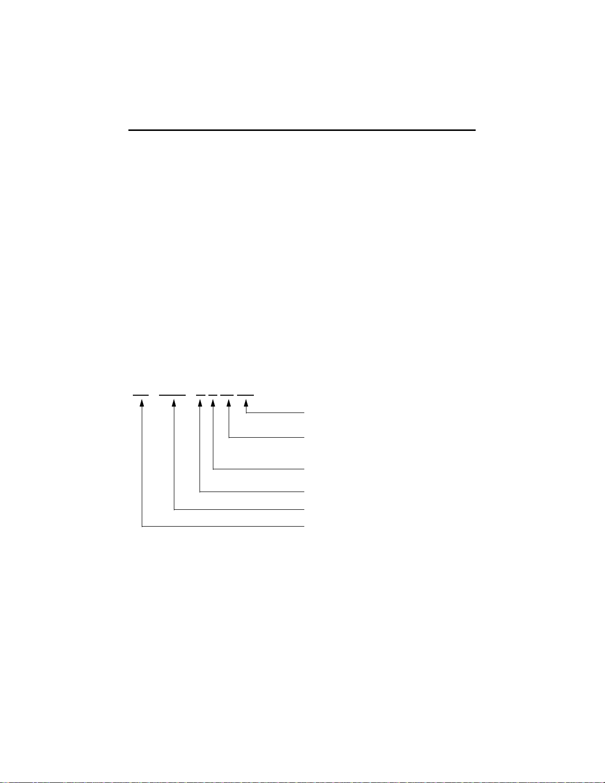
Motor Catalog Number Identification
LD - 4030 - O H 04 AA
Publication LD-IN001A-EN-P — September 2000
FACTORY DESIGNATED OPTIONS
AA Standard
OPTIONS
00 Standard
04 24VDC Brake
OPTICAL ENCODER LINE COUNT
H 2000
MOTOR WINDING Ke DESIGNATOR
FRAME SIZE
SERIES DESIGNATOR
LD Light Industrial
Page 3
LD-Series Motor Installation Instructions 3
ATTENTION
!
Before You Install the Motor
1. Remove the motor carefully from its shipping container.
2. Visually inspect the motor for any damage.
3. Examine the motor frame, front output shaft, and mounting pilot for
any defects.
4. Notify the carrier of any shipping damage immediately.
Do not open or attempt to open the motor.
Only a qualified Allen-Bradley employee can
service this type of motor
Failure to observe these safety procedures could
result in the equipment being damaged.
Using Couplings and Pulleys
Mechanical connections to the motor shaft, such as couplings and pulleys,
require a torsionally rigid coupling or a reinforced timing belt. The high
dynamic performance of servo motors can cause couplings, pulleys or
belts to loosen or slip over time. A loose or slipping connection will cause
system instability and may damage the motor shaft. All connections
between the system and the servo motor shaft must be rigid to achieve
acceptable response from the system. Periodically inspect connections to
verify their rigidity.
When mounting couplings or pulleys to the motor shaft, ensure that the
connections are properly aligned and that axial and radial loads are within
the specifications of the motor. Refer to Motor Load Force Ratings on
page 11 for guidelines on how to achieve 20,000 hours of motor bearing
life.
Publication LD-IN001A-EN-P — September 2000
Page 4

4 LD-Series Motor Installation Instructions
Preventing Electrical Noise
ElectroMagnetic Interference (EMI), commonly called noise, may
adversely impact motor performance by inducing stray signals. Effective
techniques to counter EMI include filtering the AC power, shielding and
separating signal carrying lines, and practicing good grounding
techniques.
Effective AC power filtering can be achieved by using isolated AC power
transformers or properly installed AC line filters.
To help avoid EMI:
1. Physically separate signal lines from motor cabling and power wiring.
Do not route signal wires with motor and power wires, or over the vent
openings of servo drives.
2. Ground all equipment using a single-point parallel ground system that
employs ground bus bars or large straps. If necessary, use additional
electrical noise reduction techniques to reduce EMI in noisy
environments.
Publication LD-IN001A-EN-P — September 2000
Page 5

LD-Series Motor Installation Instructions 5
ATTENTION
!
Building and Installing Cables
Knowledgeable cable routing and careful cable construction improves
system ElectroMagnetic Compatibility (EMC).
To build and install cables, perform the following steps:
1. Keep wire lengths as short as physically possible.
2. Route signal cables (encoder, serial, analog) away from motor and
power wiring.
3. Separate cables by 0.3 m (1 ft) minimum for every 9 m (30 ft) of parallel
run.
4. Ground both ends of the encoder cable shield and twist the signal wire
pairs to prevent electromagnetic interference (EMI) from other
equipment.
High voltage can be present on the shield of a
power cable, if the shield is not grounded.
Ensure there is a connection to ground for any
power cable shield.
Failure to observe these safety procedures could
result in personal injury or damage to equipment.
Publication LD-IN001A-EN-P — September 2000
Page 6

6 LD-Series Motor Installation Instructions
ATTENTION
!
Installing Your Motor
All motors include a mounting pilot for aligning the motor on a machine.
Preferred fasteners are stainless steel. The installation must comply with
all local regulations and use of equipment and installation practices that
promote electromagnetic compatibility (EMC) and safety.
Unmounted motors, disconnected mechanical
couplings, and/or disconnected cables are
dangerous if power is applied.
Disassembled equipment should be appropriately
identified (tagged-out) and access to electrical
power restricted (locked-out).
Failure to observe these safety procedures could
result in personal injury
Publication LD-IN001A-EN-P — September 2000
Page 7
LD-Series Motor Installation Instructions 7
ATTENTION
!
Guidelines for Installation
Observe the following for installing the motor.
1. Allow sufficient clearances in the area of the motor for it to stay within
its specified operating temperature range. Refer to Receiving and
Maintenance Information on page 2 for operating range. Do not
enclose the motor unless forced air is blown across the motor for
cooling. A fan blowing air across the motor will improve its
performance. Keep other heat producing devices away from the motor.
2. Refer to Mounting Dimensions on page 8 to determine the mounting
dimensions of your motor.
3. Place the motor with connectors pointing downward.
4. Properly mount and align the motor.
5. Attach all power and encoder cables after the motor is mounted and
use a drip loop in the cable to keep liquids flowing away from the
connectors.
Outer surfaces of motor can reach high
temperatures, 100° C (212° F) during motor
operation.
Take precautions to prevent accidental contact with
hot surfaces. Consider motor surface temperature
when selecting motor mating connections and
cables.
Failure to observe these safety procedures could
result in personal injury or damage to equipment.
Publication LD-IN001A-EN-P — September 2000
Page 8
8 LD-Series Motor Installation Instructions
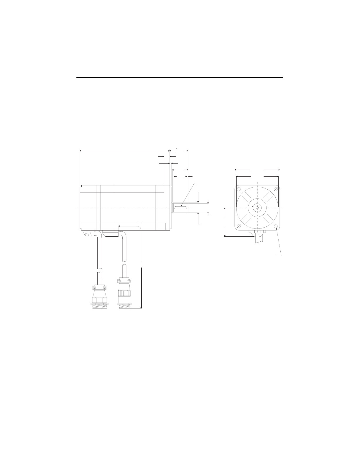
Mounting Dimensions
The dimension symbols and actual dimensions of the different models in
the LD-Series are referenced in a table on the next page.
Figure 1
Reference for Mounting Dimensions
L
BE
BB
Cable length for all motors:
1000 mm (39.37 in.)
L AH
AF
XD
XE
P
AK
S
U
EP
AB
BF = DIA. HOLES
AJ = DIA. BOLT CIRCLE
Publication LD-IN001A-EN-P — September 2000
Page 9

LD-Series Motor Installation Instructions 9
Dimension Symbol 1
(Refer to drawing)
Motor
LD-2003 LD-3009 LD-4012 LD-4030
AB mm 38 50 55 55
(in.) (1.5) (1.97) (2.16) (2.16)
AF mm 20 25 30 30
(in.) (0.78) (0.98) (1.18) (1.18)
AH mm 24 30 35 35
(in.) (0.94) (1.18) (1.38) (1.38)
AJ mm 60 90 100 100
(in.) (2.36) (3.54) (3.94) (3.94)
AK mm 50 70 80 80
(in.) (1.97) (2.76) (3.15) (3.15)
BB mm2.53.03.03.0
(in.) (0.10) (0.12) (0.12) (0.12)
BE mm5888
(in.) (0.2) (0.31) (0.31) (0.31)
BF mm4.55.56.66.6
(in.) (0.18) (0.22) (0.26) (0.26)
EP mm 12 16 19 19
(in.) (0.47) (0.63) (0.75) (0.75)
L mm 86 103 116 172
(in.) (3.38) (4.05) (4.57) (6.77)
L with Brake mm 115 130 156 212
(in.) (4.53) (5.12) (6.14) (8.35)
P mm 54 76 86 86
(in.) (2.13) (2.99) (3.39) (3.39)
S mm3 x 35 x 55 x 55 x 5
(in.) (0.12 x 0.12) (0.2 x 0.2) (0.2 x 0.2) (0.2 x 0.2)
U mm8 141616
(in.) (0.31) (0.55) (0.63) (0.63)
XD mm 12 20 25 25
(in.) (0.47) (0.79) (0.99) (0.99)
XE mm2222
(in.) (0.08) (0.08) (0.08) (0.08)
1
LD-Series motors are designed to metric dimensions. Imperial measurements are mathematical conversions.
Publication LD-IN001A-EN-P — September 2000
Page 10

10 LD-Series Motor Installation Instructions
Connector Data
The tables below list the signal descriptions for the encoder and power
connector pins.
Encoder Connector Power Connector
Pin Signal Pin Signal
1 - 8, 25-28 Open 1
9A+ 2
10 A- 3
Phase R
Phase S
Phase T
11 B+ 4 Open
12 B- 5 Ground
13 I+ 6 Open
14 I- 7
Brake+
15 HALL A+ 8 Open
16 HALL A- 9
17 HALL B+
18 HALL B-
19 HALL C+
1
Cables and drives may label the R, S and T
power phases as U, V and W respectively.
2
Open on non-brake motors.
Brake-
20 HALL C-
21 Open
22 +5 VDC
23
24
1
+5V COM not connected to motor case ground.
2
Cable Shield connected to motor case ground.
COM
Shield
1
2
Power housing: AMP 206705-2
4 5 6
7 8
BR+, BR- pin contacts: AMP 66102-8
R, S, T and Ground pin contacts: AMP
1
4 8
9
21 25
14
2015
2826
3
66098-8
Encoder housing: AMP 206152-1
Pin contacts: AMP 3-66507-0
1
1
1
2
2
3
21
9
Publication LD-IN001A-EN-P — September 2000
Page 11
LD-Series Motor Installation Instructions 11
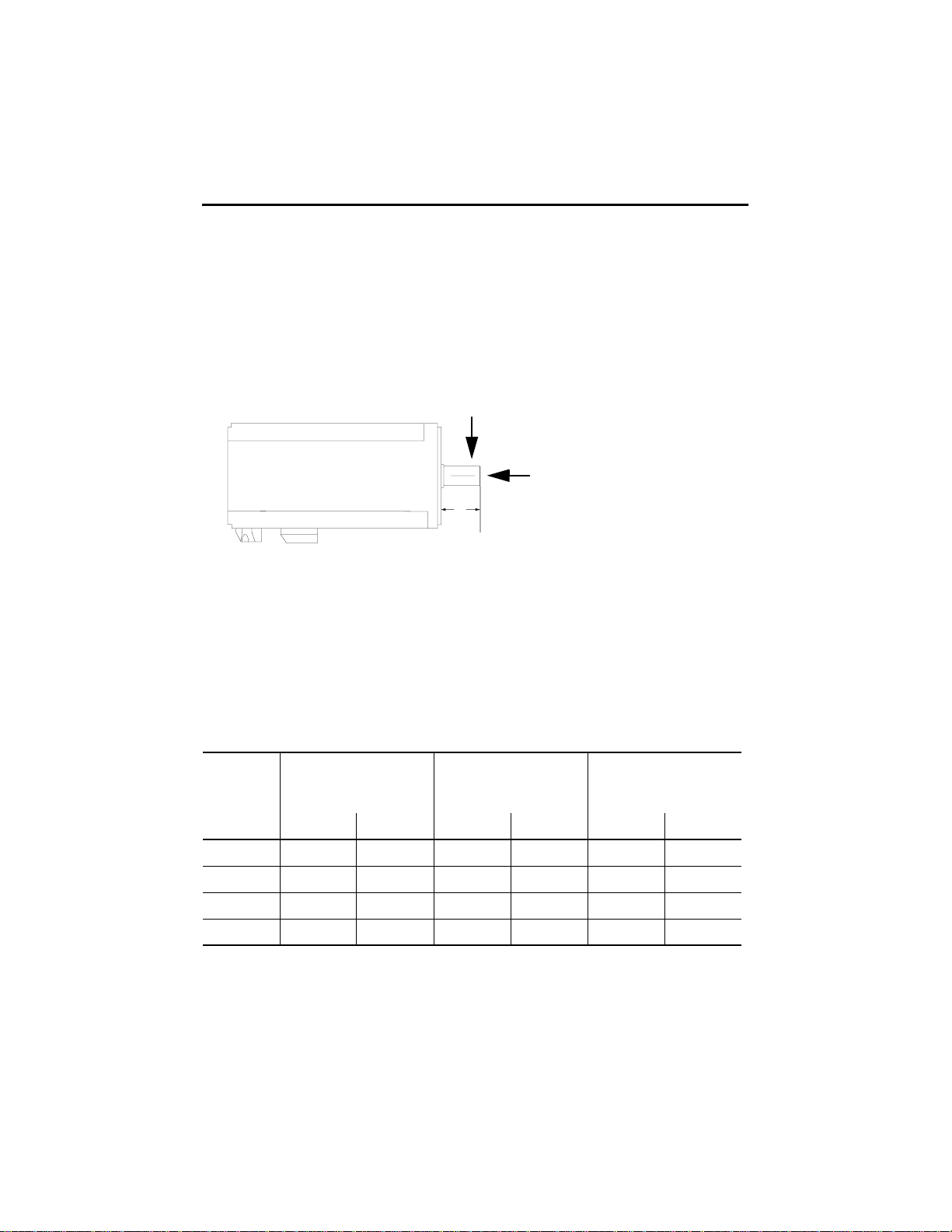
Motor Load Force Ratings
Motors are capable of operating with sustained maximum radial or
maximum axial shaft loads. The measurement points for maximum radial
and axial load forces are shown in the figure below.
Figure 2
Load Forces on Shaft
Radial load force (FR)
Axial load force (F)
AF
Radial load force (FR) applied to shaft at 2AF/3.
The following table represents load factors that provide a 20,000 hour L10
bearing fatigue life for LD-Series motors. These load factors do not
account for possible application-specific life reduction factors that may
occur, such as bearing grease contamination from external sources.
Radial Load and Axial Load Force Ratings
Motor Maximum Radial (FR)
Load
kg (lb) kg (lb) kg (lb)
LD-2003 15 (33) 3.5 (7.5) 8 (17)
LD-3009 20 (44) 4.4 (9.7) 10 (22)
LD-4012 35 (77) 8.8 (19.4) 20 (44)
LD-4030 35 (77) 8.8 (19.4) 20 (44)
Maximum Axial (F)
Load with
Radial Load
Publication LD-IN001A-EN-P — September 2000
Maximum Axial (F)
Load with
Zero Radial Load
Page 12

12 LD-Series Motor Installation Instructions
Cables and Connector Kits
Factory manufactured cables are available in standard cable lengths. They
can provide environmental sealing and shield termination. The following
cables are for connecting the LD-Series motors.
Catalog Number Description
9101-1375-XXX
9101-1385-XXX
9101-1786-XXX
1
1
2
9106-0066 Connector Kit
1
The last three digits (XXX) indicate a standard cable length:
010 = 3 m (10 ft)
025 = 7 m (25 ft)
050 = 15 m (50 ft)
075 = 23 m (75 ft)
2
The last three digits (XXX) indicate a standard cable length:
001 = 1 m (3.3 ft)
003 = 3 m (10 ft)
009 = 9 m (30 ft)
015 = 15 m (50 ft)
030 = 30 m (100 ft)
Cable, Encoder Feedback to
ULTRA 100 or ULTRA 200 Drive
(with encoder and drive mating connectors)
Cable, Motor Power to Drive
(with motor connector and pigtail to drive
terminals)
Cable, Encoder Feedback to
Ultra3000 or Ultra5000 Drive
(with encoder and 45° drive mating
connector)
(kit includes connector, pins and backshell for
both the power and encoder connectors)
Publication LD-IN001A-EN-P — September 2000
Page 13

LD-Series Motor Installation Instructions 13
Shaft Seal Kits
Shaft seal part numbers and ordering information is provided below.
Motor Series Manufacturer Part Number 1
LD-2003 4720
LD-3009 6420
LD-4012 7220
LD-4030 7220
Note: Shaft seals require a lubricant to reduce wear. Lubricant is provided with kit.
1
Shaft seals must be purchased from manufacturer:
CR Services, 735 Tollgate Road, Elgin, IL 60123
Tel: 1-800-882-0008, Fax: 1-800-526-7268
www.chicago-rawhide.com
Publication LD-IN001A-EN-P — September 2000
Page 14

14 LD-Series Motor Installation Instructions
Notes:
Publication LD-IN001A-EN-P — September 2000
Page 15

LD-Series Motor Installation Instructions 15
Publication LD-IN001A-EN-P — September 2000
Page 16

For more information refer to our web s ite: www.ab.com/motion
Publication LD-IN001A-EN-P — September 2000 PN 0013-1032-001
© 2000 Rockwell International Cor poration. Printed in the U.S.A.
 Loading...