

Page 1

This manual links to Knowledgebase Technote: Kinetix 5300 Servo Drive
Fault Codes; download the spreadsheet for offline access.
Kinetix 5300 Single-axis
EtherNet/IP Servo Drives
Catalog Numbers 2198-C1004-ERS, 2198-C1007-ERS, 2198-C1015-ERS,
2198-C1020-ERS, 2198-C2030-ERS, 2198-C2055-ERS, 2198-C2075-ERS,
2198-C4004-ERS, 2198-C4007-ERS, 2198-C4015-ERS, 2198-C4020-ERS,
2198-C4030-ERS, 2198-C4055-ERS, 2198-C4075-ERS
User Manual
Original Instructions
Page 2
Kinetix 5300 Single-axis EtherNet/IP Servo Drives User Manual
Important User Information
Read this document and the documents listed in the additional resources section about installation, configuration, and
operation of this equipment before you install, configure, operate, or maintain this product. Users are required to familiarize
themselves with installation and wiring instructions in addition to requirements of all applicable codes, laws, and standards.
Activities including installation, adjustments, putting into service, use, assembly, disassembly, and maintenance are required to
be carried out by suitably trained personnel in accordance with applicable code of practice.
If this equipment is used in a manner not specified by the manufacturer, the protection provided by the equipment may be
impaired.
In no event will Rockwell Automation, Inc. be responsible or liable for indirect or consequential damages resulting from the use
or application of this equipment.
The examples and diagrams in this manual are included solely for illustrative purposes. Because of the many variables and
requirements associated with any particular installation, Rockwell Automation, Inc. cannot assume responsibility or liability for
actual use based on the examples and diagrams.
No patent liability is assumed by Rockwell Automation, Inc. with respect to use of information, circuits, equipment, or software
described in this manual.
Reproduction of the contents of this manual, in whole or in part, without written permission of Rockwell Automation, Inc., is
prohibited.
Throughout this manual, when necessary, we use notes to make you aware of safety considerations.
WARNING: Identifies information about practices or circumstances that can cause an explosion in a hazardous environment, which may
lead to personal injury or death, property damage, or economic loss.
ATTENTION: Identifies information about practices or circumstances that can lead to personal injury or death, property damage, or
economic loss. Attentions help you identify a hazard, avoid a hazard, and recognize the consequence.
IMPORTANT Identifies information that is critical for successful application and understanding of the product.
Labels may also be on or inside the equipment to provide specific precautions.
SHOCK HAZARD: Labels may be on or inside the equipment, for example, a drive or motor, to alert people that dangerous voltage may
be present.
BURN HAZARD: Labels may be on or inside the equipment, for example, a drive or motor, to alert people that surfaces may reach
dangerous temperatures.
ARC FLASH HAZARD: Labels may be on or inside the equipment, for example, a motor control center, to alert people to potential Arc
Flash. Arc Flash will cause severe injury or death. Wear proper Personal Protective Equipment (PPE). Follow ALL Regulatory requirements
for safe work practices and for Personal Protective Equipment (PPE).
2 Rockwell Automation Publication 2198-UM005A-EN-P - October 2020
Page 3

Table of Contents
Preface
Download Firmware, AOP, EDS, and Other Files . . . . . . . . . . . . . . . . . . . . 9
Conventions Used in This Manual . . . . . . . . . . . . . . . . . . . . . . . . . . . . . . . . . 9
Access Fault Codes . . . . . . . . . . . . . . . . . . . . . . . . . . . . . . . . . . . . . . . . . . . . . . . 9
CIP Security . . . . . . . . . . . . . . . . . . . . . . . . . . . . . . . . . . . . . . . . . . . . . . . . . . . . 10
Additional Resources . . . . . . . . . . . . . . . . . . . . . . . . . . . . . . . . . . . . . . . . . . . . 10
Chapter 1
Start About the Kinetix 5300 Servo Drive System . . . . . . . . . . . . . . . . . . . . . . . . 14
Drive Hardware and Input Power Configurations. . . . . . . . . . . . . . . . . . 15
Motor and Auxiliary Feedback Configurations . . . . . . . . . . . . . . . . . . . . . 18
Typical Communication Configurations . . . . . . . . . . . . . . . . . . . . . . . . . . 19
Linear Topology . . . . . . . . . . . . . . . . . . . . . . . . . . . . . . . . . . . . . . . . . . . . . 19
Ring Topology. . . . . . . . . . . . . . . . . . . . . . . . . . . . . . . . . . . . . . . . . . . . . . . 20
Star Topology . . . . . . . . . . . . . . . . . . . . . . . . . . . . . . . . . . . . . . . . . . . . . . . 21
Safe Torque Off Configuration . . . . . . . . . . . . . . . . . . . . . . . . . . . . . . . . . . . 22
Catalog Number Explanation . . . . . . . . . . . . . . . . . . . . . . . . . . . . . . . . . . . . 23
Agency Compliance . . . . . . . . . . . . . . . . . . . . . . . . . . . . . . . . . . . . . . . . . . . . . 24
Plan the Kinetix 5300 Drive
System Installation
Mount the Kinetix 5300 Drive
System
Chapter 2
System Design Guidelines . . . . . . . . . . . . . . . . . . . . . . . . . . . . . . . . . . . . . . . 25
System Mounting Requirements . . . . . . . . . . . . . . . . . . . . . . . . . . . . . . 25
AC Line Filter Selection . . . . . . . . . . . . . . . . . . . . . . . . . . . . . . . . . . . . . . 26
Transformer Selection . . . . . . . . . . . . . . . . . . . . . . . . . . . . . . . . . . . . . . . 27
Circuit Breaker/Fuse Selection. . . . . . . . . . . . . . . . . . . . . . . . . . . . . . . . 27
24V Control Power Evaluation . . . . . . . . . . . . . . . . . . . . . . . . . . . . . . . . 29
Passive Shunt Considerations . . . . . . . . . . . . . . . . . . . . . . . . . . . . . . . . 30
Enclosure Selection . . . . . . . . . . . . . . . . . . . . . . . . . . . . . . . . . . . . . . . . . . 31
Minimum Clearance Requirements . . . . . . . . . . . . . . . . . . . . . . . . . . . 33
Electrical Noise Reduction . . . . . . . . . . . . . . . . . . . . . . . . . . . . . . . . . . . . . . . 34
HF Bond for Modules . . . . . . . . . . . . . . . . . . . . . . . . . . . . . . . . . . . . . . . . 34
HF Bond for Multiple Subpanels . . . . . . . . . . . . . . . . . . . . . . . . . . . . . . 36
Establish Noise Zones. . . . . . . . . . . . . . . . . . . . . . . . . . . . . . . . . . . . . . . . 37
Cable Categories for Kinetix 5300 Systems . . . . . . . . . . . . . . . . . . . . . 38
Noise Reduction Guidelines for Drive Accessories . . . . . . . . . . . . . . 38
Chapter 3
Determine Mounting Order. . . . . . . . . . . . . . . . . . . . . . . . . . . . . . . . . . . . . . 42
Zero-stack Tab and Cutout . . . . . . . . . . . . . . . . . . . . . . . . . . . . . . . . . . . 42
Shared-bus Connection System . . . . . . . . . . . . . . . . . . . . . . . . . . . . . . . 43
Drill-hole Patterns . . . . . . . . . . . . . . . . . . . . . . . . . . . . . . . . . . . . . . . . . . . . . . 44
Mount Your Kinetix 5300 Drive. . . . . . . . . . . . . . . . . . . . . . . . . . . . . . . . . . . 50
Rockwell Automation Publication 2198-UM005A-EN-P - October 2020 3
Page 4

Table of Contents
Chapter 4
Connector Data and Feature
Descriptions
Connect the Kinetix 5300 Drive
System
Kinetix 5300 Connector Data. . . . . . . . . . . . . . . . . . . . . . . . . . . . . . . . . . . . . 52
Safe Torque Off Connector Pinout . . . . . . . . . . . . . . . . . . . . . . . . . . . . 52
Input Power Connector Pinouts. . . . . . . . . . . . . . . . . . . . . . . . . . . . . . . 53
Shunt Resistor Connector Pinouts . . . . . . . . . . . . . . . . . . . . . . . . . . . . 53
Ethernet Communication Connector Pinout . . . . . . . . . . . . . . . . . . . 53
Digital Inputs and Auxiliary Feedback Connector Pinouts . . . . . . . 54
Motor Power, Brake, and Feedback Connector Pinouts . . . . . . . . . . 55
Understand Control Signal Specifications . . . . . . . . . . . . . . . . . . . . . . . . . 56
Digital Inputs . . . . . . . . . . . . . . . . . . . . . . . . . . . . . . . . . . . . . . . . . . . . . . . 56
Motor Holding-brake Circuit . . . . . . . . . . . . . . . . . . . . . . . . . . . . . . . . . 56
Control Power. . . . . . . . . . . . . . . . . . . . . . . . . . . . . . . . . . . . . . . . . . . . . . . 58
Ethernet Communication Specifications. . . . . . . . . . . . . . . . . . . . . . . 58
Feedback Specifications . . . . . . . . . . . . . . . . . . . . . . . . . . . . . . . . . . . . . . . . . 58
Motor Feedback Supported on the MFB Connector . . . . . . . . . . . . . 59
Auxiliary Feedback Specifications . . . . . . . . . . . . . . . . . . . . . . . . . . . . . 61
Encoder Phasing Definitions . . . . . . . . . . . . . . . . . . . . . . . . . . . . . . . . . 63
Absolute Position Feature . . . . . . . . . . . . . . . . . . . . . . . . . . . . . . . . . . . . 64
Safe Torque Off Safety Features . . . . . . . . . . . . . . . . . . . . . . . . . . . . . . . . . . 65
Servo Drives with Hardwired Safety . . . . . . . . . . . . . . . . . . . . . . . . . . . 65
Chapter 5
Basic Wiring Requirements . . . . . . . . . . . . . . . . . . . . . . . . . . . . . . . . . . . . . . 67
Build Your Own Cables. . . . . . . . . . . . . . . . . . . . . . . . . . . . . . . . . . . . . . . 68
Routing the Power and Signal Cables . . . . . . . . . . . . . . . . . . . . . . . . . . 68
Determine the Input Power Configuration . . . . . . . . . . . . . . . . . . . . . . . . 69
Three-phase Input Power. . . . . . . . . . . . . . . . . . . . . . . . . . . . . . . . . . . . . 69
Single-phase Input Power . . . . . . . . . . . . . . . . . . . . . . . . . . . . . . . . . . . . 70
Ground the Drive System . . . . . . . . . . . . . . . . . . . . . . . . . . . . . . . . . . . . . . . . 71
Ground the System Subpanel . . . . . . . . . . . . . . . . . . . . . . . . . . . . . . . . . 71
Ground Multiple Subpanels. . . . . . . . . . . . . . . . . . . . . . . . . . . . . . . . . . . 72
Wiring Requirements . . . . . . . . . . . . . . . . . . . . . . . . . . . . . . . . . . . . . . . . . . . 73
Wiring Guidelines . . . . . . . . . . . . . . . . . . . . . . . . . . . . . . . . . . . . . . . . . . . . . . 75
Wire the Power Connectors . . . . . . . . . . . . . . . . . . . . . . . . . . . . . . . . . . . . . . 76
Wire the 24V Control Power Input Connector . . . . . . . . . . . . . . . . . . 76
Wire the Input Power Connector. . . . . . . . . . . . . . . . . . . . . . . . . . . . . . 77
Wire the Digital Input Connectors. . . . . . . . . . . . . . . . . . . . . . . . . . . . . . . . 77
Wire the Safe Torque Off Connector. . . . . . . . . . . . . . . . . . . . . . . . . . . 77
Wire the Digital Inputs and Auxiliary Feedback Connector . . . . . . 78
Wire the Motor Power and Brake Connectors. . . . . . . . . . . . . . . . . . . . . . 79
Servo Motor/Actuator and Cable Compatibility . . . . . . . . . . . . . . . . . 80
Motor Power and Brake Connections . . . . . . . . . . . . . . . . . . . . . . . . . . 80
Maximum Cable Lengths . . . . . . . . . . . . . . . . . . . . . . . . . . . . . . . . . . . . . 82
Cable Preparation for Kinetix TLP Motor Power Cables. . . . . . . . . . 83
Cable Preparation for 2090-CPxM7DF Motor Power Cables . . . . . . 83
Cable Preparation for Kinetix TL and TLY Motor Power Cables. . . 86
Apply the Motor Power/brake Shield Clamp . . . . . . . . . . . . . . . . . . . . 87
Wire the Motor Feedback Connector. . . . . . . . . . . . . . . . . . . . . . . . . . . . . . 89
Cable Preparation for Kinetix TLP Feedback Cables . . . . . . . . . . . . . 90
4 Rockwell Automation Publication 2198-UM005A-EN-P - October 2020
Page 5

Configure and Start up the
Kinetix 5300 Drive System
Table of Contents
Cable Preparation for 2090-CFBM7Dx Feedback Cables . . . . . . . . . 90
Cable Preparation for Kinetix TL and TLY Feedback Cables . . . . . . 91
Motor Feedback Cable Preparation . . . . . . . . . . . . . . . . . . . . . . . . . . . . 92
2090-Series Feedback Cable Pinouts. . . . . . . . . . . . . . . . . . . . . . . . . . . 93
External Passive-shunt Resistor Connections . . . . . . . . . . . . . . . . . . . . . . 96
Ethernet Cable Connections . . . . . . . . . . . . . . . . . . . . . . . . . . . . . . . . . . . . . 97
Chapter 6
Understand the Kinetix 5300 Front Panel. . . . . . . . . . . . . . . . . . . . . . . . . . 99
Menus and Display Screen. . . . . . . . . . . . . . . . . . . . . . . . . . . . . . . . . . . 100
Startup Sequence. . . . . . . . . . . . . . . . . . . . . . . . . . . . . . . . . . . . . . . . . . . 104
Configure the Kinetix 5300 Drive . . . . . . . . . . . . . . . . . . . . . . . . . . . . . . . . 105
Set the Network Parameters . . . . . . . . . . . . . . . . . . . . . . . . . . . . . . . . . 105
Studio 5000 Logix Designer . . . . . . . . . . . . . . . . . . . . . . . . . . . . . . . . . . . . . 106
Version History . . . . . . . . . . . . . . . . . . . . . . . . . . . . . . . . . . . . . . . . . . . . 106
Install the Kinetix 5300 Add-On Profile . . . . . . . . . . . . . . . . . . . . . . . 107
Configure the Logix 5000 Controller . . . . . . . . . . . . . . . . . . . . . . . . . . . . . 107
Configure the Kinetix 5300 Drive Modules . . . . . . . . . . . . . . . . . . . . . . . 110
Configure Drive Connections. . . . . . . . . . . . . . . . . . . . . . . . . . . . . . . . 110
Continue Drive Configuration . . . . . . . . . . . . . . . . . . . . . . . . . . . . . . . 112
Configure the Motion Group . . . . . . . . . . . . . . . . . . . . . . . . . . . . . . . . . . . . 115
Configure Vertical Load Control Axis Properties . . . . . . . . . . . . . . . . . . 116
Configure Feedback-only Axis Properties. . . . . . . . . . . . . . . . . . . . . . . . . 116
Configure Induction-motor Frequency-control Axis Properties. . . . . 118
General and Motor Categories . . . . . . . . . . . . . . . . . . . . . . . . . . . . . . . 118
Basic Volts/Hertz Method . . . . . . . . . . . . . . . . . . . . . . . . . . . . . . . . . . . 119
Sensorless Vector Method . . . . . . . . . . . . . . . . . . . . . . . . . . . . . . . . . . . 120
Fan/Pump Volts/Hertz Method . . . . . . . . . . . . . . . . . . . . . . . . . . . . . . 121
Configure SPM Motor Closed-loop Control Axis Properties . . . . . . . . 122
Configure Induction-motor Closed-loop Control Axis Properties . . . 128
Configure Feedback Properties. . . . . . . . . . . . . . . . . . . . . . . . . . . . . . . . . . 133
Configure Module Properties . . . . . . . . . . . . . . . . . . . . . . . . . . . . . . . . 133
Configure Axis Properties . . . . . . . . . . . . . . . . . . . . . . . . . . . . . . . . . . . 134
Apply Power to the Kinetix 5300 Drive . . . . . . . . . . . . . . . . . . . . . . . . . . . 137
Test and Tune the Axes . . . . . . . . . . . . . . . . . . . . . . . . . . . . . . . . . . . . . . . . . 138
Test the Axes . . . . . . . . . . . . . . . . . . . . . . . . . . . . . . . . . . . . . . . . . . . . . . . 138
Tune the Axes . . . . . . . . . . . . . . . . . . . . . . . . . . . . . . . . . . . . . . . . . . . . . . 140
Troubleshoot the Kinetix 5300
Drive System
Rockwell Automation Publication 2198-UM005A-EN-P - October 2020 5
Chapter 7
Safety Precautions . . . . . . . . . . . . . . . . . . . . . . . . . . . . . . . . . . . . . . . . . . . . . 141
Interpret Status Indicators. . . . . . . . . . . . . . . . . . . . . . . . . . . . . . . . . . . . . . 141
Fault Code Overview . . . . . . . . . . . . . . . . . . . . . . . . . . . . . . . . . . . . . . . . 142
Fault Codes . . . . . . . . . . . . . . . . . . . . . . . . . . . . . . . . . . . . . . . . . . . . . . . . 143
Kinetix 5300 Drive Status Indicators . . . . . . . . . . . . . . . . . . . . . . . . . 143
General Troubleshooting . . . . . . . . . . . . . . . . . . . . . . . . . . . . . . . . . . . . . . . 144
Logix 5000 Controller and Drive Behavior . . . . . . . . . . . . . . . . . . . . . . . . 145
Web Server Interface . . . . . . . . . . . . . . . . . . . . . . . . . . . . . . . . . . . . . . . . . . . 150
Page 6

Table of Contents
Chapter 8
Remove and Replace Servo
Drives
Kinetix 5300 Safe Torque Off
Function
Before You Begin . . . . . . . . . . . . . . . . . . . . . . . . . . . . . . . . . . . . . . . . . . . . . . 155
Remove and Replace Kinetix 5300 Servo Drives . . . . . . . . . . . . . . . . . . . 156
Remove Power and All Connections . . . . . . . . . . . . . . . . . . . . . . . . . . 156
Remove the Servo Drive . . . . . . . . . . . . . . . . . . . . . . . . . . . . . . . . . . . . . 157
Replace the Servo Drive . . . . . . . . . . . . . . . . . . . . . . . . . . . . . . . . . . . . . 157
Start and Configure the Drive . . . . . . . . . . . . . . . . . . . . . . . . . . . . . . . . . . . 158
Chapter 9
Certification. . . . . . . . . . . . . . . . . . . . . . . . . . . . . . . . . . . . . . . . . . . . . . . . . . . 159
Important Safety Considerations . . . . . . . . . . . . . . . . . . . . . . . . . . . . 159
Category 3 Requirements According to ISO 13849-1 . . . . . . . . . . . . 160
Stop Category Definition . . . . . . . . . . . . . . . . . . . . . . . . . . . . . . . . . . . . 160
Performance Level (PL) and Safety Integrity Level (SIL) . . . . . . . . 160
Description of Operation . . . . . . . . . . . . . . . . . . . . . . . . . . . . . . . . . . . . . . . 160
Fault Codes . . . . . . . . . . . . . . . . . . . . . . . . . . . . . . . . . . . . . . . . . . . . . . . . 162
Probability of Dangerous Failure Per Hour . . . . . . . . . . . . . . . . . . . . . . . 164
Safe Torque Off Connector Data. . . . . . . . . . . . . . . . . . . . . . . . . . . . . . . . . 164
Wire the Safe Torque Off Circuit . . . . . . . . . . . . . . . . . . . . . . . . . . . . . . . . 165
Safe Torque Off Wiring Requirements. . . . . . . . . . . . . . . . . . . . . . . . 165
Safe Torque Off Feature . . . . . . . . . . . . . . . . . . . . . . . . . . . . . . . . . . . . . . . . 166
Safe Torque Off Feature Bypass . . . . . . . . . . . . . . . . . . . . . . . . . . . . . . 166
Cascade the Safe Torque-off Signal. . . . . . . . . . . . . . . . . . . . . . . . . . . 167
STO Recovery Time . . . . . . . . . . . . . . . . . . . . . . . . . . . . . . . . . . . . . . . . . 167
Safe Torque Off Specifications . . . . . . . . . . . . . . . . . . . . . . . . . . . . . . . . . . 168
Appendix A
Interconnect Diagrams Interconnect Diagram Notes . . . . . . . . . . . . . . . . . . . . . . . . . . . . . . . . . . . . 169
Power Wiring Examples . . . . . . . . . . . . . . . . . . . . . . . . . . . . . . . . . . . . . . . . 170
Shunt Resistor Wiring Example . . . . . . . . . . . . . . . . . . . . . . . . . . . . . . . . . 172
Kinetix 5300 Servo Drive and Rotary Motor Wiring Examples . . . . . . 173
Kinetix 5300 Drive and Linear Actuator Wiring Examples. . . . . . . . . . 179
System Block Diagrams. . . . . . . . . . . . . . . . . . . . . . . . . . . . . . . . . . . . . . . . . 184
Appendix B
Upgrade Kinetix 5300 Drive
Firmware
Before You Begin . . . . . . . . . . . . . . . . . . . . . . . . . . . . . . . . . . . . . . . . . . . . . . 185
Inhibit the Module. . . . . . . . . . . . . . . . . . . . . . . . . . . . . . . . . . . . . . . . . . 186
Upgrade Your Firmware . . . . . . . . . . . . . . . . . . . . . . . . . . . . . . . . . . . . . . . . 187
Use ControlFLASH Plus Software to Upgrade Your
Drive Firmware . . . . . . . . . . . . . . . . . . . . . . . . . . . . . . . . . . . . . . . . . . . . 187
Use ControlFLASH Software to Upgrade Your Drive Firmware. . 191
Verify the Firmware Upgrade . . . . . . . . . . . . . . . . . . . . . . . . . . . . . . . . . . . 196
6 Rockwell Automation Publication 2198-UM005A-EN-P - October 2020
Page 7

Table of Contents
Appendix C
Motor Control Feature Support Frequency Control Methods. . . . . . . . . . . . . . . . . . . . . . . . . . . . . . . . . . . . . 198
Basic Volts/Hertz . . . . . . . . . . . . . . . . . . . . . . . . . . . . . . . . . . . . . . . . . . . 199
Basic Volts/Hertz for Fan/Pump Applications . . . . . . . . . . . . . . . . 200
Sensorless Vector. . . . . . . . . . . . . . . . . . . . . . . . . . . . . . . . . . . . . . . . . . . 201
Current Limiting for Frequency Control. . . . . . . . . . . . . . . . . . . . . . . . . . 202
The Effects of Current Limiting . . . . . . . . . . . . . . . . . . . . . . . . . . . . . . 202
Enable the Current Limiting Feature . . . . . . . . . . . . . . . . . . . . . . . . . 204
Set the CurrentVectorLimit Attribute Value . . . . . . . . . . . . . . . . . . . 204
Stability Control for Frequency Control . . . . . . . . . . . . . . . . . . . . . . . . . . 205
Enable the Stability Control Feature . . . . . . . . . . . . . . . . . . . . . . . . . . 206
Skip Speeds . . . . . . . . . . . . . . . . . . . . . . . . . . . . . . . . . . . . . . . . . . . . . . . . . . . 207
Multiple Skip Speeds. . . . . . . . . . . . . . . . . . . . . . . . . . . . . . . . . . . . . . . . 208
Flux Up . . . . . . . . . . . . . . . . . . . . . . . . . . . . . . . . . . . . . . . . . . . . . . . . . . . . . . . 209
Flux Up Attributes . . . . . . . . . . . . . . . . . . . . . . . . . . . . . . . . . . . . . . . . . . 210
Configure the Flux Up Attributes. . . . . . . . . . . . . . . . . . . . . . . . . . . . . 211
Current Regulator Loop Settings . . . . . . . . . . . . . . . . . . . . . . . . . . . . . . . . 212
Motor Category . . . . . . . . . . . . . . . . . . . . . . . . . . . . . . . . . . . . . . . . . . . . . . . . 212
Motor Tests and Autotune Procedure . . . . . . . . . . . . . . . . . . . . . . . . . 214
Motor Analyzer Category Troubleshooting . . . . . . . . . . . . . . . . . . . . 215
Selection of Motor Thermal Models . . . . . . . . . . . . . . . . . . . . . . . . . . . . . . 218
Generic Motors. . . . . . . . . . . . . . . . . . . . . . . . . . . . . . . . . . . . . . . . . . . . . 218
Thermally Characterized Motors . . . . . . . . . . . . . . . . . . . . . . . . . . . . . 219
Speed Limited Adjustable Torque (SLAT) . . . . . . . . . . . . . . . . . . . . . . . . . 220
Motion Polarity Setting . . . . . . . . . . . . . . . . . . . . . . . . . . . . . . . . . . . . . 220
SLAT Min Speed/Torque . . . . . . . . . . . . . . . . . . . . . . . . . . . . . . . . . . . . 221
SLAT Max Speed/Torque . . . . . . . . . . . . . . . . . . . . . . . . . . . . . . . . . . . . 222
SLAT Attributes . . . . . . . . . . . . . . . . . . . . . . . . . . . . . . . . . . . . . . . . . . . . 222
Configure the Axis for SLAT . . . . . . . . . . . . . . . . . . . . . . . . . . . . . . . . . 223
Motion Drive Start (MDS) Instruction . . . . . . . . . . . . . . . . . . . . . . . . 226
Motor Overload Retention . . . . . . . . . . . . . . . . . . . . . . . . . . . . . . . . . . . . . . 231
Phase Loss Detection . . . . . . . . . . . . . . . . . . . . . . . . . . . . . . . . . . . . . . . . . . . 232
Phase-loss Detection Configuration . . . . . . . . . . . . . . . . . . . . . . . . . . 233
Phase Loss Detection Current Example . . . . . . . . . . . . . . . . . . . . . . . 234
Velocity Droop. . . . . . . . . . . . . . . . . . . . . . . . . . . . . . . . . . . . . . . . . . . . . . . . . 235
Closed Loop Control . . . . . . . . . . . . . . . . . . . . . . . . . . . . . . . . . . . . . . . . 235
Frequency Control . . . . . . . . . . . . . . . . . . . . . . . . . . . . . . . . . . . . . . . . . . 235
Velocity Droop Attribute . . . . . . . . . . . . . . . . . . . . . . . . . . . . . . . . . . . . 235
Velocity Droop Configuration. . . . . . . . . . . . . . . . . . . . . . . . . . . . . . . . 236
Commutation Self-sensing Startup . . . . . . . . . . . . . . . . . . . . . . . . . . . . . . 236
Commutation Test . . . . . . . . . . . . . . . . . . . . . . . . . . . . . . . . . . . . . . . . . . . . . 238
Adaptive Tuning . . . . . . . . . . . . . . . . . . . . . . . . . . . . . . . . . . . . . . . . . . . . . . . 238
Virtual Torque Sensor . . . . . . . . . . . . . . . . . . . . . . . . . . . . . . . . . . . . . . . . . . 239
Index . . . . . . . . . . . . . . . . . . . . . . . . . . . . . . . . . . . . . . . . . . . . . . . . . . . . . . . . . .241
Rockwell Automation Publication 2198-UM005A-EN-P - October 2020 7
Page 8

Table of Contents
Notes:
8 Rockwell Automation Publication 2198-UM005A-EN-P - October 2020
Page 9

Preface
This manual provides detailed installation instructions to mount, wire, and
troubleshoot the Kinetix® 5300 servo drives, and system integration for your
drive and motor/actuator combination with a Logix 5000™ controller.
This manual is intended for engineers or technicians directly involved in the
installation and wiring of the Kinetix 5300 drives, and programmers directly
involved in the operation, field maintenance, and integration of these drives
with the EtherNet/IP™ communication module or controller.
If you do not have a basic understanding of Kinetix 5300 servo drives, contact
your local Rockwell Automation sales representative for information on
available training courses.
Download Firmware, AOP, EDS, and Other Files
Conventions Used in This Manual
Access Fault Codes
Download firmware, associated files (such as AOP, EDS, and DTM), and access
product release notes from the Product Compatibility and Download Center at
rok.auto/pcdc
These conventions are used throughout this manual:
• Bulleted lists such as this one provide information, not procedural steps.
• Numbered lists provide sequential steps or hierarchical information.
For Kinetix 5300 fault code desc riptions and possibl e solutions, see
.
For Kinetix 5300 fault code descriptions and possible solutions, see
Knowledgebase Article: Kinetix 5300 Servo Drive Fault Codes
download the spreadsheet from this public article.
You will be asked to log in to your Rockwell Automation web account or
create an account if you do not have one. You do not need a support
contract to access this article.
. You can
Rockwell Automation Publication 2198-UM005A-EN-P - October 2020 9
Page 10

Preface
CIP Security
CIP Security™ is a standard, open-source communication method that helps to
provide a secure data transport across an EtherNet/IP network. It lets
CIP-connected devices authenticate each other before transmitting and
receiving data.
CIP Security uses the following security properties to help devices protect
themselves from malicious communication:
• Device Identity and Authentication
• Data Integrity and Authentication
• Data Confidentiality
Rockwell Automation uses the following products to implement CIP Security:
• FactoryTalk® Services Platform, version 6.11 or later, with the following
components enabled:
- FactoryTalk Policy Manager
- FactoryTalk System Services
• FactoryTalk Linx, version 6.11 or later
• Studio 5000® Design Environment, version 32.00.00 or later
• CIP Security-enabled Rockwell Automation® products, for example, the
product described in this publication
For more information on CIP Security, including which products support CIP
Security, see the CIP Security with Rockwell Automation Products Application
Technique, publication SECURE-AT001
.
Additional Resources
These documents contain additional information concerning related products
from Rockwell Automation.
Table 1 - Additional Resources
Resource Description
Kinetix Rotary Motion Specifications Technical Data, publication KNX-TD001
Kinetix Linear Motion Specifications Technical Data, publication KNX-TD002
Kinetix Servo Drives Specifications Technical Data, publication KNX-TD003
Kinetix Motion Accessories Specifications Technical Data, publication KNX-TD004
AC Line Filter Installation Instructions, publication 2198-IN003
Shunt Resistor Installation Instructions, publication 2097-IN002
System Design for Control of Electrical Noise Reference Manual, publication GMC-RM001
Servo Drive Installation Best Practices Application Technique,
publication MOTION-AT004
Kinetix Motion Control Selection Guide, publication KNX-SG001
Kinetix 5300 Drive Systems Design Guide, publication KNX-RM012
Motor Nameplate Datasheet Entry for Custom Motor Applications Application Technique,
publication 2198-AT002
Product specifications for Kinetix VPL, VPF, VPH, and VPS, Kinetix MPL, MPM, MPF,
and MPS, Kinetix TL and TLY, and Kinetix TLP rotary motors.
Product specifications for Kinetix MPAS/MPMA, MPAR, and MPAI linear actuators,
LDAT-Series linear thrusters, and LDC-Series™ and LDL-Series™ linear motors.
Product specifications for Kinetix Integrated Motion over the EtherNet/IP
network, Integrated Motion over sercos interface, EtherNet/IP networking, and
component servo drive families.
Product specifications for 2090-Series motor and interface cables, low-profile
connector kits, drive power components, and other servo drive accessory items.
Provides information on how to install AC line filters designed for Kinetix 5300,
Kinetix 5500, and Kinetix 5700 servo drive systems.
Provides information on how to install and wire Bulletin 2097 shunt resistors.
Information, examples, and techniques designed to minimize system failures
caused by electromagnetic interference (EMI) sources.
Best practice examples to help reduce the number of potential noise or
electromagnetic interference (EMI) sources in your system and to make sure that
the noise sensitive components are not affected by the remaining noise.
Overview of Kinetix servo drives, motors, actuators, and motion accessories
designed to help make initial decisions for the motion control products best
suited for your system requirements.
System design guide to select the required (drive specific) drive module, power
accessory, feedback connector kit, and motor cable catalog numbers for your
Kinetix 5300 servo drive system.
Provides information on the use of nameplate data entry for custom induction
motors and permanent-magnet motors that are used in applications with
Kinetix 5700 servo drives.
10 Rockwell Automation Publication 2198-UM005A-EN-P - October 2020
Page 11

Table 1 - Additional Resources (continued)
Resource Description
Virtual Torque Sensor Application Technique, publication 2198-AT003
Vertical Load and Holding Brake Management Application Technique,
publication MOTION-AT003
Integrated Motion on the EtherNet/IP Network Reference Manual,
publication MOTION-RM003
Integrated Motion on the EtherNet/IP Network Configuration and Startup User Manual,
publication MOTION-UM003
CIP Security with Rockwell Automation Products Application Technique,
publication SECURE-AT001
System Security Design Guidelines Reference Manual, SECURE-RM001
GuardLogix 5570 Controllers User Manual, publication 1756-UM022
GuardLogix 5580 Controllers User Manual, publication 1756-UM543
Compact GuardLogix 5370 Controllers User Manual, publication 1769-UM022
Compact GuardLogix 5380 Controllers User Manual, publication 5069-UM001
GuardLogix 5570 and Compact GuardLogix 5370 Controller Systems Safety Reference
Manual, publication 1756-RM099
GuardLogix 5580 and Compact GuardLogix 5380 Controller Systems Safety Reference
Manual, publication 1756-RM012
Rockwell Automation Product Selection
website http://www.rockwellautomation.com/global/support/selection.page
Motion Analyzer System Sizing and Selection Tool
website https://motionanalyzer.rockwellautomation.com/
Product Certifications website, rok.auto/certifications
ControlFLASH Firmware Upgrade Kit User Manual, publication 1756-UM105
Rockwell Automation Industrial Automation Glossary, publication AG-7.1
Industrial Automation Wiring and Grounding Guidelines, publication 1770-4.1
.
Provides information on the configuration and application of the virtual torque
sensor capability of the Kinetix 5300 drives. The capability can be leveraged for
analytics to improve the machine commissioning and maintenance experience.
Provides information on vertical loads and how the servo motor holding-brake
option can be used to help keep a load from falling.
Information on the AXIS_CIP_DRIVE attributes and the configuration software
control modes and methods.
Information on how to configure and troubleshoot your ControlLogix® and
CompactLogix™ EtherNet/IP network modules.
Provides information on CIP Security, including which Rockwell Automation
products support CIP Security.
Provides guidance on how to conduct security assessments, implement Rockwell
Automation products in a secure system, harden the control system, manage
user access, and dispose of equipment.
Provides information on how to install, configure, program, and use ControlLogix
controllers and GuardLogix® controllers in Studio 5000 Logix Designer® projects.
Provides information on how to install, configure, program, and use
CompactLogix and Compact GuardLogix controllers.
Provides information on how to achieve and maintain Safety Integrity Level (SIL)
and Performance Level (PL) safety application requirements for GuardLogix and
Compact GuardLogix controllers.
Online product selection and system configuration tools, including AutoCAD (DXF)
drawings.
Comprehensive motion application sizing tool used for analysis, optimization,
selection, and validation of your Kinetix Motion Control system.
Provides declarations of conformity, certificates, and other certification details.
Provides information on how to upgrade your drive firmware by using
ControlFLASH™ software.
A glossary of industrial automation terms and abbreviations.
Provides general guidelines for installing a Rockwell Automation industrial
system.
Preface
You can view or download publications at rok.auto/literature.
Rockwell Automation Publication 2198-UM005A-EN-P - October 2020 11
Page 12

Preface
Notes:
12 Rockwell Automation Publication 2198-UM005A-EN-P - October 2020
Page 13

Chapter 1
Start
Use this chapter to become familiar with the Kinetix® 5300 drive system and
obtain an overview of the installation configurations.
Top ic Pa ge
About the Kinetix 5300 Servo Drive System 14
Drive Hardware and Input Power Configurations 15
Motor and Auxiliary Feedback Configurations 18
Typical Communication Configurations 19
Safe Torque Off Configuration 22
Catalog Number Explanation 23
Agency Compliance 24
Rockwell Automation Publication 2198-UM005A-EN-P - October 2020 13
Page 14

Chapter 1 Start
About the Kinetix 5300 Servo Drive System
The Kinetix 5300 servo drives are designed to provide a Kinetix Integrated
Motion solution for your drive and motor/actuator application.
Table 2 - Kinetix 5300 Drive System Overview
Drive System
Component
Kinetix 5300
Servo Drives
24V Shared-bus
Connector Kits
Feedback
Connector Kit
Connector Sets
Logix 5000™
Controller
Platform
Studio 5000®
Environment
Rotary Servo
Motors
Linear Actuators
Linear Motors
Induction Motors N/A Induction motors with open-loop frequency control and closed-loop control are supported.
2090-Series
Cables
Ethernet Cables
AC Line Filters
24V DC Power
Supply
External Shunt
Resistors
Cat. No. Description
100V-class and 200V-class (single-phase or three-phase) and 400V-class (three-phase) drives operate in standalone
2198 -Cxxxx-ERS
2198-TCON-24VDCIN36 Control power input connector for all frame sizes.
2198 -H040-x-x Control power T-connector and bus-bar connectors for Frame 1 and 2 drives.
2198 -H070-x-x Control power T-connector and bus-bar connectors for Frame 3 drives.
2198 -K53CK-D15 M
2198-CONKIT-PWR20 Connector set included with the Frame 1 and 2 drives (except 2198-C2030 drives). Replacement sets are also available.
2198-CONKIT-PWR30 Connector set included with 2198-C2030 drives. Replacement sets are also available.
2198-CONKIT-PWR75 Connector set included with Frame 3 drives. Replacement sets are also available.
Bulletin 1769
Bulletin 5069
1756-EN2T module
1756-EN2TR module
1756-EN3TR module
N/A
Kinetix MP Compatible rotary motors include 200V and 400V-class Kinetix MPL, MPM, MPF, MPS servo motors.
Kinetix TLP Compatible rotary motors include 200V and 400V-class Kinetix TLP servo motors.
Kinetix TL and TLY Compatible rotary motors include 200V-class Kinetix TL and TLY servo motors.
Kinetix MP and
LDAT-Series
LDC-Series and
LDL-Series
2090-CTFB-MxDx-xxxxx Motor feedback cables for Kinetix TLP motors.
2090-CTPx-MxDx-xx
2090-CFBM6Dx-CxAAxx Motor feedback cables for Kinetix TLY servo motors.
2090-CPxM6DF-16AAxx Motor power/brake cables for Kinetix TLY servo motors.
2090-DANFCT-Sxx Motor feedback cables for Kinetix TL servo motors.
2090-DANPT-16Sxx Motor power cables for Kinetix TL servo motors.
2090-DANBT-18Sxx Motor brake cables for Kinetix TL servo motors.
2090-CFBM7DF-CEAxxx Motor feedback cables for Kinetix MP motors/actuators, LDAT-Series linear thrusters, and LDC/LDL-Series linear motors.
2090-CPxM7DF-xxAxxx Motor power/brake cables for Kinetix MP motors/actuators, LDAT-Series linear thrusters, and LDC/LDL-Series linear motors.
2090-XXNFMF-Sxx
2090-CFBM7DF-CDAFxx
1585J-M8CBJM-x
1585J-M8UBJM-x
2198 -DB08 -F
2198-DBR20-F
2198-DBR40-F
1606-XLxxx Bulletin 1606 24V DC power supply for control circuitry, digital inputs, and safety inputs.
2097-R6 and 2097-R7
2198-R004, 2198-R014,
2198 -R031
configurations. Modules can be zero-stacked from drive-to-drive and are compatible with the 24V DC shared-bus
connection system to extend control power to multiple drives. Drives feature Safe Torque Off via the hardwired (STO)
connector.
Motor feedback connector kit with 15-pin connector plug for compatible motors and actuators. Kit features battery backup
for Kinetix TLP, TL, and TLY multi-turn encoders.
Integrated Motion on the EtherNet/IP network in CompactLogix™ 5370, CompactLogix 5380, and CompactLogix 5480
controllers and Integrated Safety in Compact GuardLogix® 5370 controllers. Linear, device-level ring (DLR), and star topology
is supported.
EtherNet/IP network communication modules for use with ControlLogix® 5570, ControlLogix 5580, GuardLogix 5570, and
GuardLogix 5580 controllers. Linear, device-level ring (DLR), and star topology is supported.
Studio 5000 Logix Designer® application, version 33.00 or later, provides support for programming, commissioning, and
maintaining the CompactLogix and ControlLogix controller families.
Compatible linear actuators include 200V and 400V-class Kinetix MPAS and MPMA linear stages, Kinetix MPAR and MPAI linear
actuators, and LDAT-Series linear thrusters.
Compatible motors include LDC-Series™ iron-core and LDL-Series™ ironless linear motors.
xxx Moto
r power/brake cables for Kinetix TLP motors.
Standard and continuous-flex feedback cables that include additional conductors for use with incremental encoders.
Ethernet cables are available in standard lengths. Shielded cable is required to meet EMC specifications.
Bulletin 2198 three-phase AC line filters are required to meet CE and are available for use in all Kinetix 5300 drive systems.
Bulletin 2097 and 2198 external passive shunt resistors are available for when the internal shunt capability of the drive is
exceeded.
14 Rockwell Automation Publication 2198-UM005A-EN-P - October 2020
Page 15
Start Chapter 1
1606-XL
Power Supply
Input
Allen-Bradley
L3L2
L1
24+
DC+ SH
24-
SB+
SBS1
SC
S2
MBRK
W
V
U
1
10
1
2
MFB
Single-phase or
Three-phase
Input Power
Line
Disconnect
Device
Circuit
Protection
2097-Rx or 2198-Rxxxx
Shunt Resistor
(optional component)
2198 -Cxxxx-ERS Drive
(top view)
AC Input Power
Bonded Cabinet
Ground Bus
AC Input Wiring to Standard
Input Connector
1606-XLxxx
24V DC Control, Digital Inputs,
and Motor Brake Power
(customer-supplied)
2198 -Cxxxx-ERS Drive
(front view)
24V DC Input Wired to
Standard Input Connector
2198-DB08-F or
2198 -DBRxx-F
AC Line Filter
(required for CE)
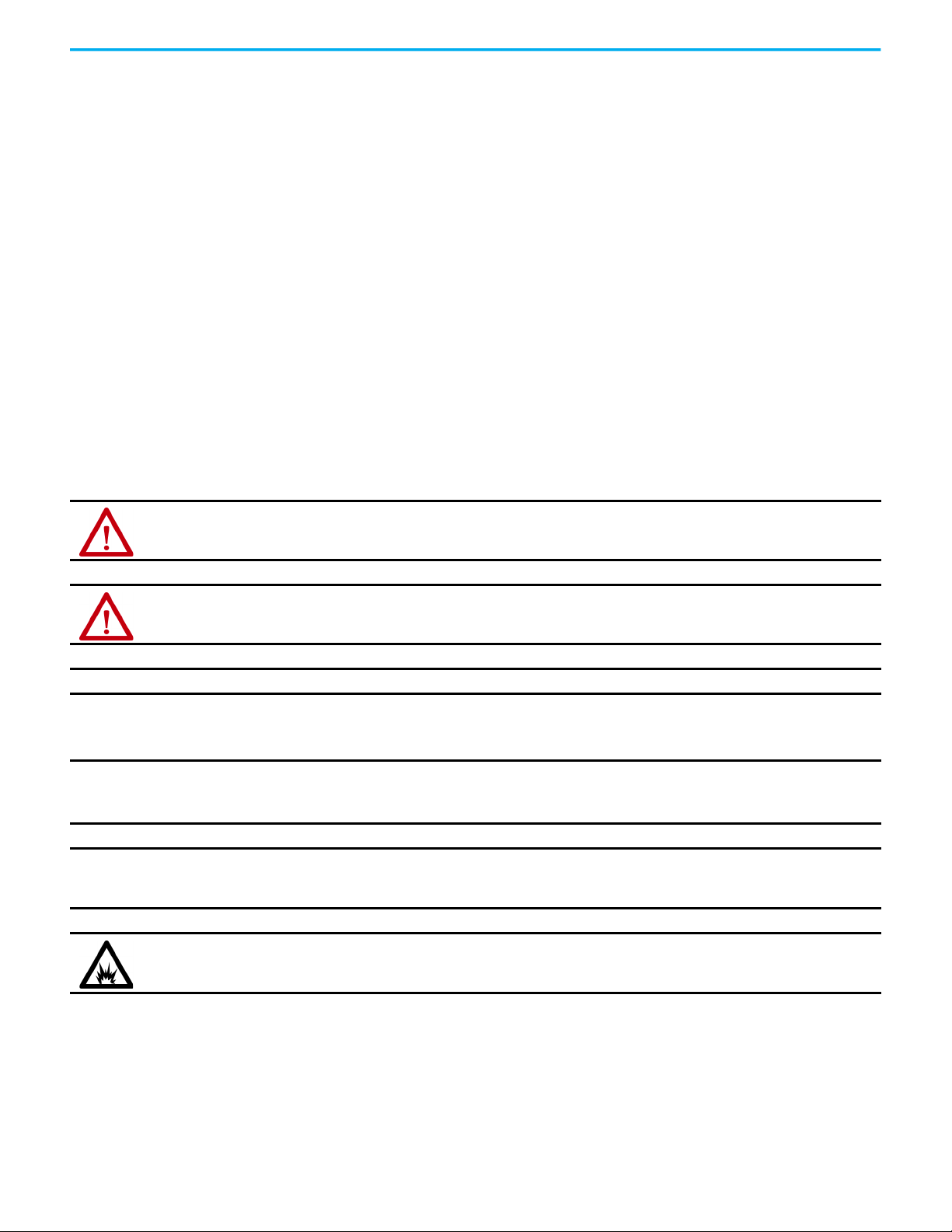
Drive Hardware and Input Power Configurations
Typical Kinetix 5300 systems include single-phase and three-phase standalone
configurations.
In this example, a single drive is shown with input power to the standard AC
and 24V DC input connectors.
Figure 1 - Typical Kinetix 5300 Standalone Installation
Rockwell Automation Publication 2198-UM005A-EN-P - October 2020 15
Page 16
Chapter 1 Start
1606-XL
Power Supply
Input
Allen-Bradley
L3L2
L1
DC+ SH
SB+
SBS1
SC
S2
MBRK
W
V
U
1
10
1
2
MFB
L3L2
L1
DC+ SH
SB+
SBS1
SC
S2
MBRK
W
V
U
1
10
1
2
MFB
Single-phase or
Three-phase
Input Power
Line
Disconnect
Device
Circuit
Protection
2097-Rx or 2198-Rxxxx
Shunt Resistor
(optional component)
2198 -Cxxxx-ERS Drives
(top view)
AC Input Power
Bonded Cabinet
Ground Bus
2198-DB08-F or
2198 -DBRxx-F
AC Line Filter
(required for CE)
Shared 24V (control power input)
2198 -H0x0-x-x shared-bus connection
system for 24V bus-sharing configurations.
AC Input Wiring
Connectors
1606-XLxxx
24V DC Control, Digital Inputs,
and Motor Brake Power
(customer-supplied)
219 8-Cxxxx-ERS Drives
(front view)
2198-DB08-F or
2198 -DBRxx-F
AC Line Filter
(required for CE)
Circuit
Protection
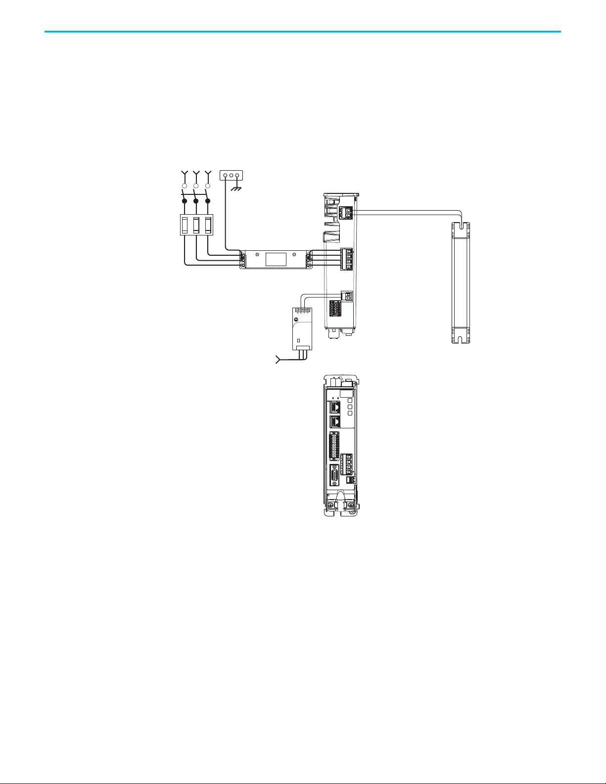
In this example, two drives are shown with input power to the standard input
connectors and control power input by using 24V shared-bus connectors.
With two or more drives in the drive configuration, each drive requires AC
input power and line filter.
Figure 2 - Typical Kinetix 5300 Installation with 24V Shared-bus Connectors
16 Rockwell Automation Publication 2198-UM005A-EN-P - October 2020
Page 17
Start Chapter 1
1606-XL
Power Supply
Input
Allen-Bradley
L3L2
L1
DC+ SH
SB+
SBS1
SC
S2
L3L2
L1
DC+ SH
SB+
SBS1
SC
S2
24+
24-
24+
24-
2198 -Cxxxx-ERS Drives
(top view)
AC Input Power
24V DC connector wiring (control power input)
to additional Kinetix 5300 servo drives.
1606-XLxxx
24V DC Control, Digital Inputs,
and Motor Brake Power
(customer-supplied)
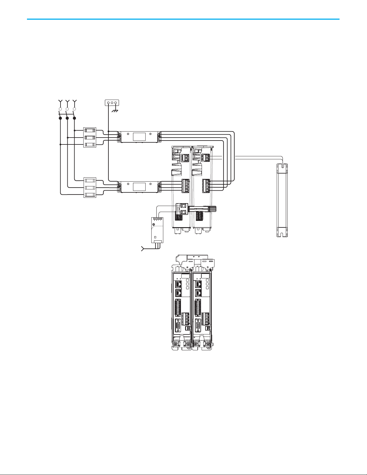
With two or more drives in the configuration and the 24V shared-bus
connectors are not used, each drive requires 24V DC input power.
Figure 3 - Typical Kinetix 5300 Installation without 24V Shared-bus Connectors
Rockwell Automation Publication 2198-UM005A-EN-P - October 2020 17
Page 18
Chapter 1 Start
MFB
1
10
20
11
20
MBRK+
MBRK-
MBRK
W
V
U
1
10
1
2
CA
T
.
N
O
.
L
D
C-M0
7
5
5
0
0
S
E
R
IA
L
NO
.
X
X
XX
X
X
X
XX
S
E
R
I
ES
A
w
ww
.a
b
.c
o
m
M
A
D
E
IN
U
S
A
MFB
20
MBRK
W
V
U
1
10
1
2
MFB
20
MBRK
W
V
U
1
10
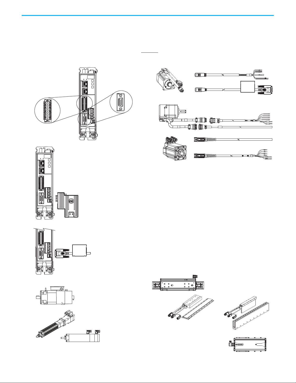
Digital Inputs and Auxiliary Feedback Connector
• Accepts incremental encoder feedback (TTL)
–Load feedback (dual loop)
– Master feedback
– Feedback-only
2090-CFBM7Dx and 2090-CPxM7DF
Motor Feedback and Power Cables
Kinetix MPAR Electric Cylinders
(MPAR-B3xxxx electric cylinder is shown)
Kinetix MP Motors and Actuators
(MPL-Bxxxx motor is shown)
LDAT-Sxxxxxx-xDx
Linear Thrusters
2198-K53CK-D15M Feedback Connector Kit
Accepts multiple encoder feedback types and provides battery-backup for multi-turn position data:
• Hiperface high-resolution absolute multi-turn and single-turn for:
– Kinetix MPL-A/Bxxx-S/M, MPM-A/Bxxx-S/M, MPF-A/Bxxx-S/M, MPS-A/Bxxx-S/M servo motors
– Kinetix MPL-A/Bxxx-E/V servo motors
– Kinetix MPAS (ballscrew), MPAR, MPAI linear actuators
–LDAT-Series (-xDx) linear thrusters
• Nikon (24-bit) high-resolution serial encoder
–Kinetix TLP-A/Bxxx-xxx-D servo motors
• Tamagawa (17-bit) high-resolution serial encoder
–Kinetix TL-AxxxP-B servo motors
–Kinetix TLY-AxxxP-B servo motors
15-pin Motor Feedback
(MFB) Connector
2198 -Cxxxx-ERS Drive
(front view)
Kinetix MPAS Linear Stages
(MPAS-B9xxx ballscrew linear stage is shown)
Kinetix MPAI Heavy-duty Electric Cylinders
(MPAI-B3xxxx heavy-duty electric cylinder is shown)
Induction Rotary Motors
• Open or closed loop
• With or without feedback
2090-CTFB-MxDD and 2090-CTPx-MxDF
Motor Feedback and Power Cables
2090-CFBM6Dx and 2090-CPxM6DF
Motor Feedback and Power Cables
20-pin I/O Connector With
Aux Feedback Connections
Kinetix TLP Motors
(TLP-A100 motor is shown)
Kinetix TL/TLY Motors
(TLY-A110 motor is shown)
LDC-Series Linear Motors
(LDC-Cxxxxxxx linear motor shown)
LDL-Series Linear Motors
(LDL-
xxxxxxxx li
near motor shown)
2090-C
TFB-MxDD Feedback Cable
Provides battery-backup for multi-turn position data:
• Nikon (24-bit) high-resolution serial encoder
– Kinetix TLP-A/Bxxx-xxx-D servo motors
• Generic sin/cos or digital AqB with UVW incremental encoders
–MPL-A/B15xxx-H, MPL-A/B2xxx-H, MPL-A/B3xxx-H, MPL-A/B4xxx-H,
MPL-A/B45xxx-H rotary motors
–Kinetix TLY-Axxxx-H servo motors
-LDAT-Series (-xBx) linear thrusters
- LDC-Series and LDL-Series linear motors
– Kinetix MPAS (direct drive)
• Support for 3rd party closed-loop control of Induction motors
Battery
Box
Motor and Auxiliary Feedback Configurations
Feedback connections are made at the 15-pin motor feedback (MFB) connector
and auxiliary feedback connector. These examples list the feedback types and
illustrate the use of compatible rotary motors and linear products with motor
cables and the 2198-K53CK-D15M connector kit. For motor power and brake
connections, see page 80
Figure 4 - Feedback Configuration Examples
.
18 Rockwell Automation Publication 2198-UM005A-EN-P - October 2020
Page 19
Start Chapter 1
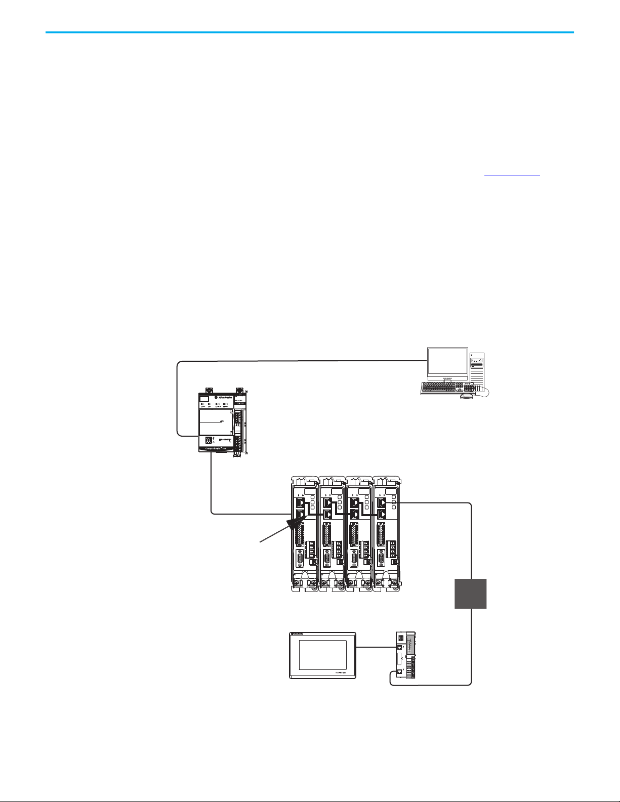
CompactLogix 5380 Controller
Studio 5000 Logix Designer
Application
1585J-M8CBJM-x
Ethernet (shielded) Cable
1734-AENTR POINT I/O™
EtherNet/IP Adapter
CompactLogix Controller Programming Network
PanelView™ 5310
Display Terminal
1585J-M8CBJM-OM15
0.15 m (6 in.) Ethernet cable
for drive-to-drive connections.
Kinetix 5300 Servo Drive System
842E-CM Integrated
Motion Encoder
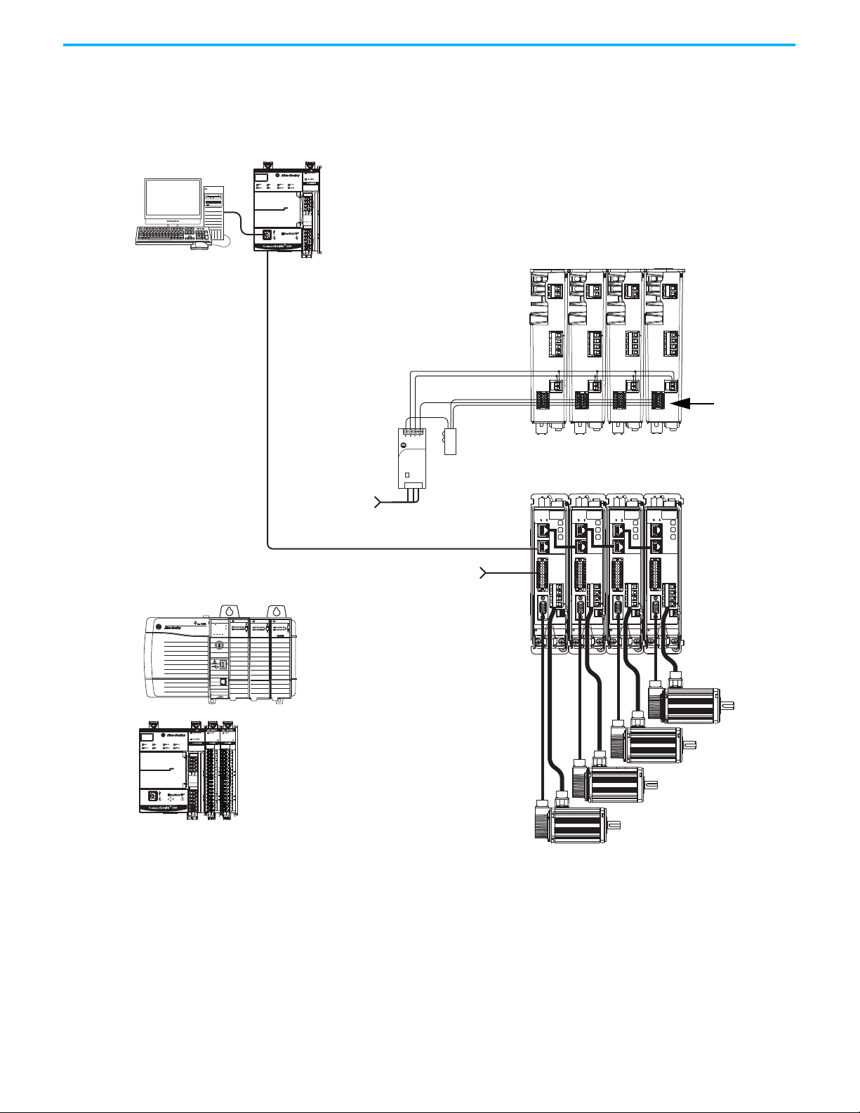
Typical Communication Configurations
The Kinetix 5300 drives support any Ethernet topology including linear, ring,
and star by using ControlLogix or CompactLogix controllers.
These examples feature the CompactLogix 5380 programmable automation
controllers (Bulletin 5069) that are part of the Logix 5000 family of controllers.
The applications range from standalone systems to more complex systems
with devices that are connected to the controller via an EtherNet/IP™ network.
Refer to CompactLogix 5380, Compact GuardLogix 5380, and CompactLogix
5480 Controller Specifications Technical Data, publication 5069-TD002
, for
more information on CompactLogix 5380 controllers.
Linear Topology
In this example, all devices are connected in linear topology. The Kinetix 5300
drives include dual-port connectivity, however, if any device becomes
disconnected, all devices downstream of that device lose communication.
Devices without dual ports must include the 1783-ETAP module or be
connected at the end of the line.
Figure 5 - Kinetix 5300 Linear Communication Installation
2
2
1
1
10
1
MFB
10
1
U
V
W
MBRK
MBRK
MFB
2
1
10
1
U
V
W
MFB
2
1
10
1
U
U
V
V
W
W
MBRK
MBRK
MFB
Rockwell Automation Publication 2198-UM005A-EN-P - October 2020 19
Page 20
Chapter 1 Start
02
0
1734-AENTR
Module
Status
Network
Activity
Network
Status
Point Bus
Status
System
Power
Field
Power
POINT I O
Link 1
Activity/
Status
Link 2
Activity/
Status
MBRK
W
V
U
1
10
1
2
MFB
MBRK
W
V
U
1
2
MFB
MBRK
W
V
U
1
2
MFB
MBRK
W
V
U
1
2
MFB
1
10
1
10
1
10
1734-AENTR POINT I/O
EtherNet/IP Adapter
CompactLogix Controller Programming Network
1585J-M8CBJM-OM15
0.15 m (6 in.) Ethernet cable
for drive-to-drive connections.
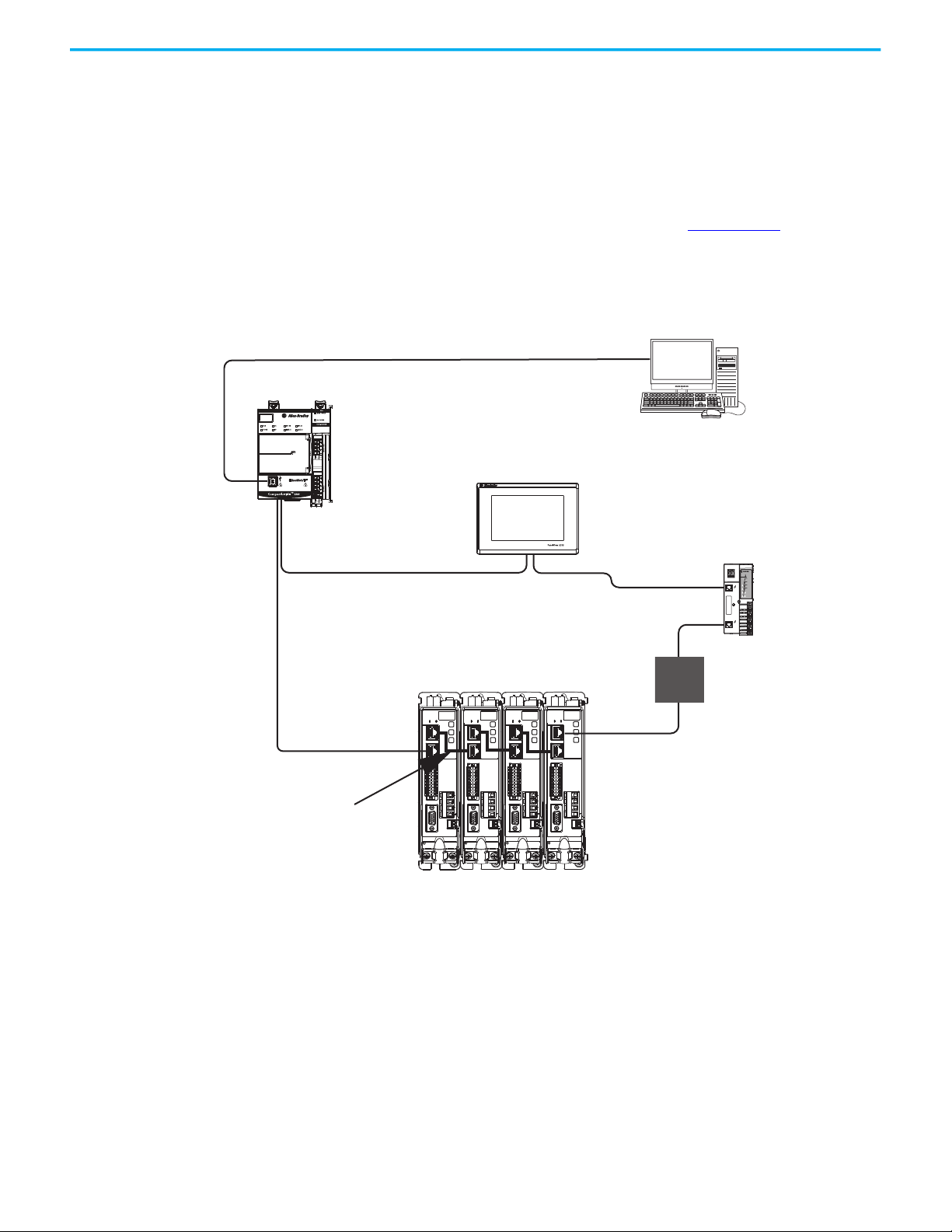
PanelView 5310
Display Terminal
Kinetix 5300 Servo Drive System
CompactLogix 5380 Controller
Studio 5000 Logix Designer
Application
1585J-M8CBJM-x Ethernet
(shielded) Cable
842E-CM Integrated
Motion Encoder
Ring Topology
In this example, the devices are connected by using ring topology. If only one
device in the ring is disconnected, the rest of the devices continue to
communicate. For ring topology to work correctly, a device level ring (DLR)
supervisor is required (for example, the CompactLogix controller). DLR is an
ODVA standard. For more information, refer to the EtherNet/IP Embedded
Switch Technology Application Guide, publication ENET-AP005
Devices without dual ports require a 1783-ETAP module to complete the
network ring.
Figure 6 - Kinetix 5300 Ring Communication Installation
.
20 Rockwell Automation Publication 2198-UM005A-EN-P - October 2020
Page 21
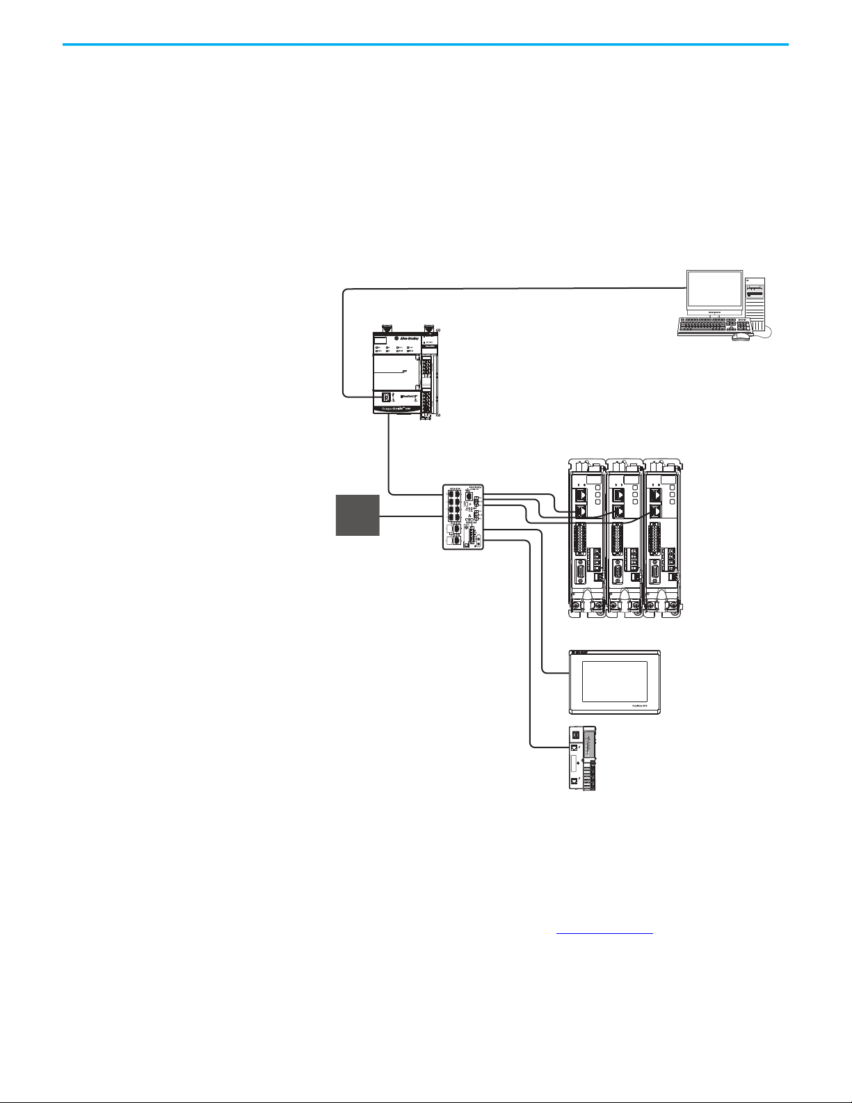
Start Chapter 1
1585J-M8CBJM-x
Ethernet (shielded) Cable
1734-AENTR POINT I/O
EtherNet/IP Adapter
CompactLogix Controller Programming Network
PanelView 5310
Display Terminal
1783-BMS
Stratix® 5700
Switch
Kinetix 5300 Servo Drive System
CompactLogix 5380 Controller
Studio 5000 Logix Designer
Application
842E-CM Integrated
Motion Encoder
Star Topology
In this example, the devices are connected by using star topology. Each device
is connected directly to the switch.
Kinetix 5300 drives have dual ports, but in star topology all drives are
connected to the switch, so the drives and other devices operate
independently. The loss of one device does not impact the operation of other
devices.
Figure 7 - Kinetix 5300 Star Communication Installation
You can use the 842E-CM integrated motion encoder for applications
requiring an external encoder for gearing or camming to the Kineitx 5300
drive. By providing auxiliary feedback directly through the EtherNet/IP
network, the 842E-CM encoder helps eliminate the need for point-to-point
wiring while letting customers use the encoder in a variety of network
topologies. For more information, see the 842E-CM Integrated Motion on
EtherNet/IP Product Profile, publication 842ECM-PP001
2
2
2
1
1
1
1
1
1
10
10
10
U
V
W
MBRK
MBRK
MFB
MFB
U
U
V
V
W
W
MBRK
MFB
.
Rockwell Automation Publication 2198-UM005A-EN-P - October 2020 21
Page 22
Chapter 1 Start
1585J-M8CBJM-x
Ethernet (shielded) Cable
Studio 5000 Logix Designer
Application
AC Input Power
Safety
Device
2198 -Cxxxx-ERS Servo Drives
(front view)
Digital Inputs to Sensors and Control String
1606-XLxxx
24V DC Control, Digital Inputs,
and Motor Brake Power
(customer-supplied)
Kinetix TLP
Servo Motors
Safe Torque Off
(STO) Connectors
Any Logix 5000 Controller with Motion EtherNet/IP Capability
(CompactLogix 5380 controller is shown)
2198 -Cxxxx-ERS Servo Drives
(top view)
ControlLogix 5570 Controllers or
GuardLogix 5570 Safety Controllers
ControlLogix 5580 Controllers or
GuardLogix 5580 Safety Controllers
CompactLogix 5370 Controllers or
Compact GuardLogix 5370 Safety Controllers
CompactLogix 5380 or 5480 Controllers or
Compact GuardLogix 5380 Safety Controllers
Safe Torque Off Configuration
The 2198-Cxxxx-ERS drives use the Safe Torque Off (STO) connector for wiring
external safety devices and cascading hardwired safety connections from one
drive to another.
Figure 8 - Safe Torque Off (hardwired) Configuration
Allen-Bradley
1606-XL
Power Supply
Input
DC+ SH
DC+ SH
DC+ SH
DC+ SH
L3L2
L3L2
L3L2
L3L2
L1
L1
24-
24-
24+
24+
SB+
SB+
SB+
SBS1
SC
S2
SB-
SB-
S1
S1
SC
SC
S2
S2
L1
L1
24-
24-
24+
24+
SB+
SBS1
SC
S2
TM
DC INPUT
DC INPUT
Logix5585
0000
SAFETY ON
NET
LINK
OKFORCESDRUN
AC OUTPUT
2
1
10
1
MFB
2
2
2
1
1
1
10
10
10
1
1
1
U
U
V
V
W
W
MBRK
MBRK
MBRK
MFB
MFB
U
U
V
V
W
W
MBRK
MFB
22 Rockwell Automation Publication 2198-UM005A-EN-P - October 2020
Page 23

Start Chapter 1
Catalog Number
Kinetix 5300 drive catalog numbers and performance descriptions.
Explanation
Table 3 - Kinetix 5300 Servo Drives
Drive Cat. No. Frame Size Input Voltage
2198 -C1004- ERS 1
2198-C1007-ERS 1
2198-C1015-ERS 2
2198-C1020-ERS 2
2198-C2030-ERS 2
2198-C2055-ERS 3 10.30 40.2 108.0
2198-C2075-ERS 3 12.22 47.7 127.5
2198-C4004-ERS 1
2198-C4007-ERS 1 1.55 2.9 9.3
2198-C4015-ERS 2 2.78 5.2 18.0
2198-C4020-ERS 2 3.90 7.3 23.8
2198-C4030-ERS 2 6.25 11.7 34.1
2198-C4055-ERS 3 12.08 22.6 58.5
2198-C4075-ERS 3 14.70 27.5 73.5
85…132V rms single-phase
170…253V rms single-phase
170…253V rms three-phase
170…253V rms three-phase
342…528V rms three-phase
Continuous Output Power
kW
0.22
0.46
0.72
0.36
0.76
1.18
0.67
1.41
2.18
0.97
2.02
3.13
5.02 19.6 61.0
0.86 1.6 5.3
Continuous Output Current
A (rms)
2.8
4.6
8.5
12.2
Peak Output Current
A (rms)
6.6
9.5
9.5
9.7
15.5
15.5
12.2
20.5
29.2
25.0
40.6
40.6
Table 4 - Shared-bus Connector Kit Catalog Numbers
Kit Cat. No. Frame Size Description
2198-TCON-24VDCIN36 1, 2, or 3 Control power input connector
2198-H040-P-T 1 or 2
2198 -H070-P -T 3
• Control power T-connector
• Bus-bar connectors, quantity 2
• Control power T-connector
• Bus-bar connectors, quantity 2
Table 5 - Kinetix 5300 Servo Drive Accessories
Cat. No. Description
2198-K53CK-D15M 15-pin motor-feedback connector kit.
2198-CONKIT-PWR20
2198-CONKIT-PWR30 Connector set included with 2198-C2030 drives. Replacement sets are also available.
2198-CONKIT-PWR75 Connector set included with Frame 3 drives. Replacement sets are also available.
Connector set included with the Frame 1 and 2 drives (except 2198-C2030 drives).
Replacement sets are also available.
Rockwell Automation Publication 2198-UM005A-EN-P - October 2020 23
Page 24

Chapter 1 Start
Agency Compliance If this product is installed within the European Union and has the CE mark,
the following regulations apply.
ATTENTION: The method of grounding the AC line filter and drive must
match. Failure to do this renders the filter ineffective and can cause
damage to the filter. For grounding examples, refer to Determine the Input
Power Configuration on page 69.
For more information on electrical noise reduction, refer to the System Design
for Control of Electrical Noise Reference Manual, publication GMC-RM001
To comply with IEC 61800-3 (category C3) and IEC 61800-5-2, these
requirements apply:
• Install an AC line filter (catalog numbers 2198-DBR20-F, 2198-DBR40-F,
or 2198-DB08-F) with 50 mm (1.97 in.) minimum clearance between the
drive and filter. Minimize the cable length as much as possible.
• Bond drive and line filter grounding screws by using a braided ground
strap as shown in Figure 36 on page 71
• Use 2090-Series motor power cables or use connector kits and connect
the cable shields to the subpanel with clamp provided.
• Use 2090-Series motor feedback cables or use connector kits and
properly connect the feedback cable shield.
• Drive-to-motor cables must not exceed 50 m (164 ft), depending on AC
input power and feedback type. See Maximum Cable Lengths
for specifications.
• Install the Kinetix 5300 system inside an enclosure. Run input power
wiring in conduit (grounded to the enclosure) outside of the enclosure.
• Separate signal and power cables. Segregate input power wiring and
motor power cables from control wiring and motor feedback cables. Use
shielded cable for power wiring and provide a grounded 360° clamp
termination.
.
on page 82
.
Refer to Appendix A on page 169
interconnect diagrams.
for input power wiring and drive/motor
24 Rockwell Automation Publication 2198-UM005A-EN-P - October 2020
Page 25
Chapter 2
Plan the Kinetix 5300 Drive System Installation
This chapter describes system installation guidelines used in preparation for
mounting your Kinetix® 5300 drive components.
Top ic Pa ge
System Design Guidelines 25
Electrical Noise Reduction 34
ATTENTION: Plan the installation of your system so that you can perform all
cutting, drilling, tapping, and welding with the system removed from the
enclosure. Because the system is of the open type construction, be careful
to keep metal debris from falling into it. Metal debris or other foreign matter
can become lodged in the circuitry and result in damage to the components.
System Design Guidelines Use the information in this section when designing your enclosure and
planning to mount your system components on the panel.
For on-line product selection and system configuration tools, including
AutoCAD (DXF) drawings of the product, refer to
https://www.rockwellautomation.com/global/support/selection.page
System Mounting Requirements
• To comply with UL and CE requirements, the Kinetix 5300 drive systems
must be enclosed in a grounded conductive enclosure offering protection
as defined in standard IEC 60529 to IP20 such that they are not accessible
to an operator or unskilled person. A NEMA 4X enclosure exceeds these
requirements providing protection to IP66.
• To maintain the functional safety rating of the Kinetix 5300 drive system,
this enclosure must be appropriate for the environmental conditions of
the industrial location and provide a protection class of IP54 or higher.
• The panel that you install inside the enclosure for mounting your system
components must be on a flat, rigid, vertical surface that won’t be
subjected to shock, vibration, moisture, oil mist, dust, or corrosive vapors
in accordance with pollution degree 2 (IEC 61800-5-1) because the
product is rated to protection class IP20 (IEC 60529). To comply with UL
applications, cabinet ventilation is allowed on the left side and right side
of the panel.
• Size the drive enclosure so as not to exceed the maximum ambient
temperature rating. Consider heat dissipation specifications for all drive
components.
.
Rockwell Automation Publication 2198-UM005A-EN-P - October 2020 25
Page 26

Chapter 2 Plan the Kinetix 5300 Drive System Installation
• Drive-to-motor cables must not exceed 50 m (164 ft), depending on input
voltage and feedback type. Refer to Maximum Cable Lengths
for specifications.
on page 82
IMPORTANT
System performance was tested at these cable length
specifications. These limitations also apply when meeting CE
requirements.
• Use high-frequency (HF) bonding techniques to connect the modules,
enclosure, machine frame, and motor housing, and to provide a lowimpedance return path for high-frequency (HF) energy and reduce
electrical noise.
Bond drive and line filter grounding screws by using a braided ground strap as
shown in Figure 36 on page 71
.
Refer to the System Design for Control of Electrical Noise Reference Manual,
publication GMC-RM001
, to better understand the concept of electrical noise
reduction.
AC Line Filter Selection
An AC line filter is required to meet CE requirements. Install an AC line filter
with 50 mm (1.97 in.) minimum clearance between the drive and filter.
Minimize the cable length as much as possible.
Table 6 - AC Line Filter Selection
Drive Cat. No. Frame Size
2198-C1004-ERS
2198-C1007-ERS
2198-C1015-ERS
2198-C1020-ERS
2198 -C2030-ERS
2198-C2075-ERS
2198 -C4004-ERS
2198-C4007-ERS
2198-C4015-ERS
2198-C4030-ERS 2198-DBR20-F
2198-C4055-ERS
2198-C4075-ERS
12198-DB08-F
2
3
1
22198 -C4020-ERS
32198-DBR40-F
AC Line Filter
Cat. No.
2198-DBR20-F
2198-DBR40-F2198-C2055-ERS
2198 -DB08 -F
26 Rockwell Automation Publication 2198-UM005A-EN-P - October 2020
Page 27

Plan the Kinetix 5300 Drive System Installation Chapter 2
Transformer Selection
The servo drive does not require an isolation transformer for three-phase
input power. However, a transformer can be required to match the voltage
requirements of the drive to the available service.
To size a transformer for the main AC power inputs, refer to the Kinetix 5300
power specifications in the Kinetix Servo Drives Technical Data, publication
KNX-TD003
.
IMPORTANT
When using an autotransformer, make sure that the phase to neutral/
ground voltage does not exceed the input voltage ratings of the drive.
IMPORTANT
Use a form factor of 1.5 for three-phase power (where form factor is
used to compensate for transformer, drive module, and motor losses,
and to account for utilization in the intermittent operating area of the
torque speed curve).
Follow these guidelines when specifying the use of line reactors:
• For single-phase drives up to 138V line to line or line to neutral, a line
reactor must be used if the source transformer is greater than 15 kVA,
max and 3% impedance, min.
• For single-phase drives 170V…253V line to neutral or three-phase drives
170V…253V line to line, a line reactor must be used if the source
transformer is greater than 75 kVA, max and 3% impedance, min.
• For three-phase drives 342V…528V line to line, a line reactor must be used
if the source transformer is greater than 150 kVA, max and 3%
impedance, min.
EXAMPLE
Sizing a transformer to the power requirements of the drive:
2198-C2030-ERS = 5.02 kW x 1.5 = 7.53 KVA transformer (minimum)
2198-C4015-ERS = 2.78 kW x 1.5 = 4.17 KVA transformer (minimum)
See Kinetix Servo Drives Specifications Technical Data, publication
KNX-TD003
, for Kinetix 5300 drive specifications, including power ratings.
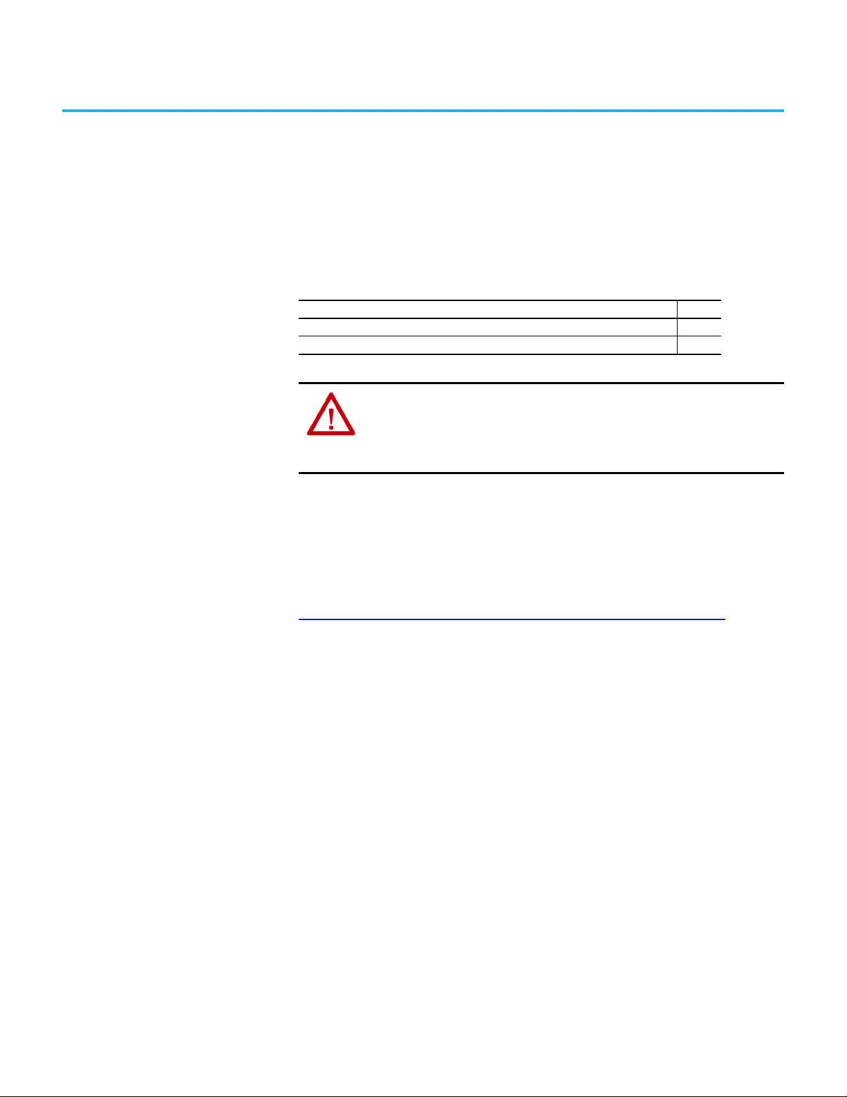
Circuit Breaker/Fuse Selection
The Kinetix 5300 drives use internal solid-state motor short-circuit protection and,
when protected by suitable branch circuit protection, are rated for use on a circuit
capable of delivering up to 200,000 A (fuses, UL applications), 10,000 A (miniature
circuit breakers), and 65,000 A (molded-case circuit breakers).
Refer to Power Wiring Examples
ATTENTION: Do not use circuit protection devices on the output of an AC
drive as an isolating disconnect switch or motor overload device. These
devices are designed to operate on sine wave voltage and the drive’s PWM
waveform does not allow it to operate properly. As a result, damage to the
device occurs.
Rockwell Automation Publication 2198-UM005A-EN-P - October 2020 27
, on page 170, for the wiring diagram.
Page 28

Chapter 2 Plan the Kinetix 5300 Drive System Installation
Table 7 - Kinetix 5300 UL/CSA Circuit Protection Specifications
Drive Cat. No.
2198-C1004-ERS
2198-C1007-ERS KTK-R-10 140U-D6D3-B80
2198-C1015-ERS KTK-R-15 140U-D6D3-C12
2198-C1020-ERS KTK-R-25 140U-D6D3-C20
2198-C2030-ERS KTK-R-30 140U-D6D3-C30
2198-C2055-ERS LPJ-50SP 140G-G6C3-C50
2198-C2075-ERS LPJ-60SP 140G-G6C3-C60
2198-C4004-ERS
2198-C4007-ERS KTK-R-6 140U-D6D3-B40
2198-C4015-ERS KTK-R-12 140U-D6D3-B80
2198-C4020-ERS KTK-R-15 140U-D6D3-C12
2198-C4030-ERS KTK-R-25 140U-D6D3-C15
2198-C4055-ERS LPJ-30SP 140U-D6D3-C30
2198-C4075-ERS LPJ-35SP 140U-D6D3-C30
2198-C1004-ERS
2198-C1007-ERS KTK-R-10 140U-D6D2-B80
2198-C1015-ERS KTK-R-15 140U-D6D2-C12
2198-C1020-ERS KTK-R-25 140U-D6D2-C20
2198-C1004-ERS
2198-C1007-ERS KTK-R-10 140U-D6D2-B80
2198-C1015-ERS KTK-R-15 140U-D6D2-C12
2198-C1020-ERS KTK-R-25 140U-D6D2-C20
AC Inpu t Voltage,
nom
200…240V AC
380…480V AC
100…120V AC
200…240V AC
Phase
Three phase
Single phase
Bussmann Fuses
Cat. No.
KTK-R-6 140U-D6D3-B40
KTK-R-3 140U-D6D3-B20
KTK-R-6 140U-D6D2-B40
KTK-R-6 140U-D6D2-B40
Molded Case CB
Cat. No.
Table 8 - Kinetix 5300 IEC (non-UL/CSA) Circuit Protection Specifications
Drive Cat. No.
2198-C1004-ERS
2198-C1007-ERS 10 1489-M3C100 140U-D6D3-B80
2198-C1015-ERS 16 1489-M3C160 140U-D6D3-C12
2198-C1020-ERS 25 1489-M3C250 140U-D6D3-C20
2198-C2030-ERS 32 1489-M3C400 140U-D6D3-C30
2198-C2055-ERS 40 – 140G-G6C3-C50
2198-C2075-ERS 50 – 140G-G6C3-C60
2198-C4004-ERS
2198-C4007-ERS 6 1489-M3C060 140U-D6D3-B40
2198-C4015-ERS 12 1489-M3C100 140U-D6D3-B80
2198-C4020-ERS 16 1489-M3C130 140U-D6D3-C12
2198-C4030-ERS 25 1489-M3C200 140U-D6D3-C15
2198-C4055-ERS 32 1489-M3C350 140U-D6D3-C30
2198-C4075-ERS 32 1489-M3C400 140U-D6D3-C30
2198-C1004-ERS
2198-C1007-ERS 10 1489-M2C100 140U-D6D2-B80
2198-C1015-ERS 16 1489-M2C160 140U-D6D2-C12
2198-C1020-ERS 25 1489-M2C250 140U-D6D2-C20
AC Input Voltage,
nom
200…240V AC
380…480V AC
100…120V AC
or
200…240V AC
Phase
Three phase
Single phase
DIN gG Fuses
Amps, max
6 1489-M3C060 140U-D6D3-B40
2 1489-M3C030 140U-D6D3-B20
6 1489-M2C060 140U-D6D2-B40
Miniature CB
Cat. No.
Molded Case CB
Cat. No.
28 Rockwell Automation Publication 2198-UM005A-EN-P - October 2020
Page 29

Plan the Kinetix 5300 Drive System Installation Chapter 2
24V Control Power Evaluation
The Kinetix 5300 drive system requires 24V DC input for its control circuitry.
Due to the 24V shared-bus connection system and the 24V current
requirements of the Kinetix 5300 drives, a thorough evaluation of control
power is required prior to implementation. Consider the following when
sizing such a system:
• Verify that the 24V DC power supply is capable of supplying the 24V
current requirements of your Kinetix 5300 drive system. See Control
Power on page 58 to determine the 24V current requirements.
For systems with a high 24V current demand, consider installing a separate 24V
power supply for each drive to more evenly divide the 24V current demand.
• Verify that the wiring being used is capable of supplying the Kinetix 5300
drive system with a voltage within the 24V input-voltage range; 24V ±10%
(21.6…26.4V DC). Consider the following:
- Mount the 24V power supply as close to the Kinetix 5300 drive system
as possible to minimize input voltage drop.
- Install larger gauge wire, up to 2.5 mm
power when using the connector plugs included with the module; or
use the 24V shared-bus connection system to lower the DC wire
resistance with up to 10 mm
2
(6 AWG) and result in a lower voltage
drop.
• For best practices of twisting 24V wires and routing cleanly, refer to the
System Design for Control of Electrical Noise Reference Manual,
publication GMC-RM001
.
2
(14 AWG) for 24V control
IMPORTANT
The 24V current demand, wire gauge, and wire length all impact the
voltage drop across the wiring being used.
Rockwell Automation Publication 2198-UM005A-EN-P - October 2020 29
Page 30
Chapter 2 Plan the Kinetix 5300 Drive System Installation
2198-R014 and 2198-R031
Shunt Modules
2097-R6, 2097-R7, and
2198-R004 Shunt Resistors
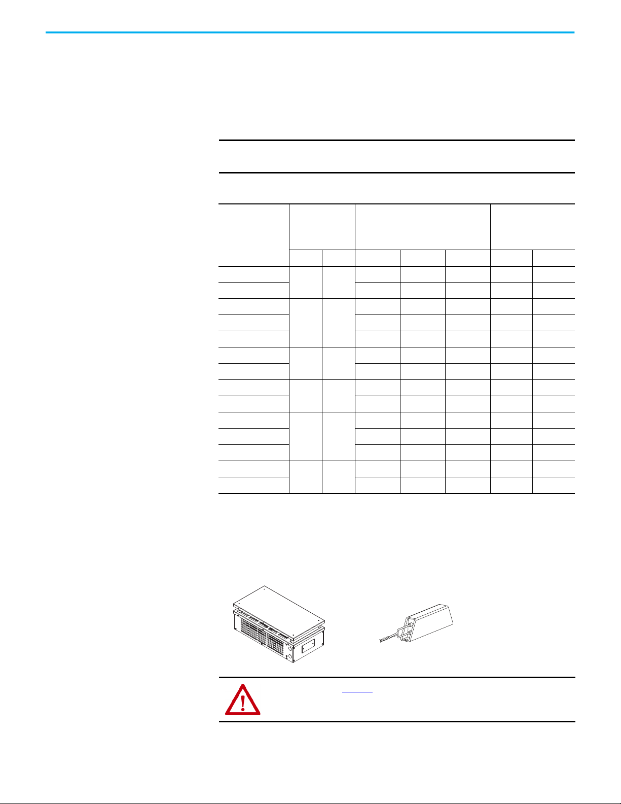
Passive Shunt Considerations
The Kinetix 5300 drives include an internal shunt that is wired to the shunt
resistor connector at the factory. Bulletin 2097-Rx and 2198-Rxxxx external
passive shunts are also available to provide additional shunt capacity for
applications where the internal shunt capacity is exceeded.
IMPORTANT
Keep the internal shunt connected unless you have an external passive
shunt to connect.
Table 9 - Passive-shunt Options
Internal Shunt
Drive Cat. No.
2198-C1004-ERS
2198-C1007-ERS – – – X X
2198-C1015-ERS
2198-C1020-ERS X – X X X
2198-C2030-ERS X – X X X
2198-C2055-ERS
2198-C2075-ERS X X X X X
2198-C4004-ERS
2198-C4007-ERS – – – X X
2198-C4015-ERS
2198-C4020-ERS X – X X X
2198-C4030-ERS X – X X X
2198-C4055-ERS
2198-C4075-ERS X X X X X
(1) Shunt resistor selection is based on the needs of your actual hardware configuration.
Specifications
ΩW2198-R004 2198-R014 2198-R031 2097-R6 2097-R7
100 30
60 50
40 75
100 30
60 50
40 75
–––XX
X–XXX
XXXXX
–––XX
X–XXX
XXXXX
Bulletin 2198
External Shunt Module
Cat. No.
(1)
Bulletin 2097
External Shunt Module
Cat. No.
(1)
Catalog numbers 2198-R014 and 2198-R031 are composed of resistor coils that
are housed inside an enclosure. Catalog numbers 2097-R6, 2097-R7, and
2198-R004 are shunt resistors without an enclosure.
Figure 9 - External Passive Shunts
ATTENTION: See Table 10 for supported shunt modules. Using an
unsupported shunt module can lead to (drive-side) shunt circuitry damage,
shunt damage, or drive faults.
30 Rockwell Automation Publication 2198-UM005A-EN-P - October 2020
Page 31

Plan the Kinetix 5300 Drive System Installation Chapter 2
A =
0.38Q
1.8T - 1.1
Table 10 - External Shunt Module Specifications
Shunt Module
Cat. No.
2097-R6 75 150 0.3 (0.7)
2097-R7 150 80 0.2 (0.4)
2198-R004 33 400 1.8 (4.0)
2198-R014 9.4 1400 9.1 (20)
2198 -R031 33 310 0
(1) The 2198-R031 shunt is limited to 2000 W when used with 2198-C1015-ERS, 2198-C1020-ERS, 2198-C2030-ERS, 2198-C4015-ERS,
2198-C4020-ERS, 2198-C4030-ERS (frame 2) drives.
Resistance
Ohms
Continuous Power
W
(1)
Weight, approx
kg (lb)
16.8 (37)
How the Bulletin 2097-Rx and 2198-Rxxx shunts connect to the Kinetix 5300
drive is explained in External Passive-shunt Connections
illustrated with interconnect diagrams in Passive Shunt Wiring Examples
page 359
.
on page 178 and
on
Enclosure Selection
This example is provided to assist you in sizing an enclosure for your
Kinetix 5300 drive system. You need heat dissipation data from all components
planned for your enclosure to calculate the enclosure size (refer to Table 11
).
IMPORTANT To comply with UL requirements, the minimum cabinet size must be
508 mm (20.0 in.), height; 406 mm (16.0 in.), width; and 300 mm (11.8 in.)
depth.
With no active method of heat dissipation (such as fans or air conditioning)
either of the following approximate equations can be used.
Metric Standard English
4.08Q
A =
T - 1.1
Where T is temperature difference between inside
air and outside ambient (°C), Q is heat generated in
enclosure (Watts), and A is enclosure surface area
2
). The exterior surface of all six sides of an
(m
enclosure is calculated as
A = 2dw + 2dh + 2wh A = (2dw + 2dh + 2wh) /144
Where d (depth), w (width), and h (height) are in meters.
Where T is temperature difference between inside
air and outside ambient (°F), Q is heat generated in
enclosure (Watts), and A is enclosure surface area
(ft2). The exterior surface of all six sides of an
enclosure is calculated as
If the maximum ambient rating of the Kinetix 5300 drive system is 50 °C
(122 °F) and if the maximum environmental temperature is 20 °C (68 °F), then
T=30. In this example, the total heat dissipation is 416 W (sum of all
components in enclosure). So, in the equation below, T=30 and Q=416.
A =
0.38 (416)
1.8 (30) - 1.1
= 2.99 m
2
In this example, the enclosure must have an exterior surface of at least 2.99 m
2
If any portion of the enclosure is not able to transfer heat, do not include that
value in the calculation.
Rockwell Automation Publication 2198-UM005A-EN-P - October 2020 31
.
Page 32

Chapter 2 Plan the Kinetix 5300 Drive System Installation
Because the minimum cabinet depth to house the Kinetix 5300 system
(selected for this example) is 300 mm (11.8 in.), the cabinet needs to be
approximately 1500 x 700 x 300 mm (59.0 x 27.6 x 11.8 in.) HxWxD.
1.5 x (0.300 x 0.70) + 1.5 x (0.300 x 2.0) + 1.5 x (0.70 x 2.0) = 3.31 m
2
Because this cabinet size is considerably larger than what is necessary to house
the system components, it can be more efficient to provide a means of cooling
in a smaller cabinet. Contact your cabinet manufacturer for options available
to cool your cabinet.
Table 11 - Power Dissipation Specifications
Kinetix 5300 Drive
Cat. No.
2198-C1004-ERS
2198-C1007-ERS 14 19 24 30 37
2198-C1015-ERS 26 36 47 59 71
2198-C1020-ERS 35 52 71 91 112
2198-C2030-ERS 53 87 124 164 206
2198-C2055-ERS 87 139 193 250 308
2198-C2075-ERS 97 159 225 293 364
2198-C4004-ERS
2198-C4007-ERS 20 30 39 48 58
2198-C4015-ERS 33 48 62 78 93
2198-C4020-ERS 39 58 79 101 124
2198-C4030-ERS 57 89 123 157 193
2198-C4055-ERS 112 171 231 293 356
2198-C4075-ERS 134 204 273 344 417
2198-C1004-ERS
2198-C1007-ERS 12 17 21 27 32
2198-C1015-ERS 23 32 42 53 64
2198-C1020-ERS 30 44 59 77 96
2198-C1004-ERS
2198-C1007-ERS 14 19 24 30 37
2198-C1015-ERS 25 36 47 59 72
2198-C1020-ERS 35 52 72 92 115
(1) Internal shunt power is not included in the calculations and must be added based on utilization.
AC Input,
nom
200…240V
three-phase
380…480V
three-phase
100…120V
single-phase
200…240V
single-phase
20% 40% 60% 80% 100%
12 16 20 25 29
16 21 26 31 36
11 14 18 22 26
12 16 20 25 30
Usage as a % of Rated Power Output
(watts)
(1)
32 Rockwell Automation Publication 2198-UM005A-EN-P - October 2020
Page 33

Plan the Kinetix 5300 Drive System Installation Chapter 2
MBRK
W
V
U
1
10
1
2
Clearance right of the
drive is not required.
Clearance left of the
drive is not required.
Kinetix 5300
Servo Drive
40 mm (1.57 in.) clearance below
drive for airflow and installation.
40 mm (1.57 in.) clearance above
drive for airflow and installation.
Refer to the Kinetix Servo Drives
Technical Data, publication KNX-TD003
,
for Kinetix 5300 drive dimensions.
MBRK
W
V
U
1
10
1
2
MFB
MBRK
W
V
U
1
10
1
2
MFB
MBRK
W
V
U
1
10
1
2
MFB
50 mm
(1.97 in.)
50 mm
(1.97 in.)
50 mm
(1.97 in.)
50 mm
(1.97 in.)
Zero-stack Tab and
Cutout Aligned
The 24V shared-bus system
is not shown for clarity.
Wire Connection
(1)
Ter m in al s
Wire Connection
(1)
Ter m in al s
Minimize Cable Length from Filter to Drive
Minimum Clearance Requirements
This section provides information to assist you in sizing your cabinet and
positioning your Kinetix 5300 drive:
• Additional clearance is required for cables and wires or the 24V DC
shared-bus connection system connected to the top of the drive.
• Additional clearance is required if other devices are installed above and/
or below the drive and have clearance requirements of their own.
• Additional clearance left and right of the drive is required when mounted
adjacent to noise sensitive equipment or clean wire ways.
Figure 10 - Minimum Clearance Requirements
IMPORTANT
Mount the drive in an upright position as shown to provide proper air
flow.
In 24V shared-bus configurations (optional), drives must be spaced by aligning
the zero-stack tab and cutout. Install the AC line filter (required for CE) with
50 mm (1.97 in.) minimum clearance between the drive and filter or between
filters, when more than one filter is used. Minimize the cable length as much
as possible.
Figure 11 - 24V Shared-bus and Line Filter Clearance Requirements
(1) Clearance required at the terminals for NEC specified bend radius depends on the wire size in use.
Rockwell Automation Publication 2198-UM005A-EN-P - October 2020 33
Page 34

Chapter 2 Plan the Kinetix 5300 Drive System Installation
Electrical Noise Reduction This section outlines best practices that minimize the possibility of noise-
related failures as they apply specifically to Kinetix 5300 system installations.
For more information on the concept of high-frequency (HF) bonding, the
ground plane principle, and electrical noise reduction, refer to the System
Design for Control of Electrical Noise Reference Manual, publication
GMC-RM001
HF Bond for Modules
Bonding is the practice of connecting metal chassis, assemblies, frames,
shields, and enclosures to reduce the effects of electromagnetic interference
(EMI).
Unless specified, most paints are not conductive and act as insulators. To
achieve a good bond between power rail and the subpanel, surfaces need to be
paint-free or plated. Bonding metal surfaces creates a low-impedance return
path for high-frequency energy.
.
IMPORTANT
Improper bonding of metal surfaces blocks the direct return path and allows
high-frequency energy to travel elsewhere in the cabinet. Excessive highfrequency energy can effect the operation of other microprocessor controlled
equipment.
To improve the bond between the power rail and subpanel, construct
your subpanel out of zinc plated (paint-free) steel.
34 Rockwell Automation Publication 2198-UM005A-EN-P - October 2020
Page 35

Plan the Kinetix 5300 Drive System Installation Chapter 2
Stud-mounting the Subpanel
to the Enclosure Back Wall
Stud-mounting a Ground Bus
or Chassis to the Subpanel
Subpanel Weld ed Stud
Scrape Paint
Flat Washer
If the mounting bracket is coated with
a non-conductive material (anodized or
painted), scrape the material around
the mounting hole.
Star Washer
Nut
Nut
Flat Washer
Mounting Bracket or
Ground Bus
Use a wire brush to remove paint from
threads to maximize ground connection.
Back Wall of
Enclosure
Welded Stud
Subpanel
Star Washer
Use plated panels or scrape paint on
front of panel.
Subpanel
Nut
Nut
Star Washer
Flat Washer
Star Washer
Star Washer
Scrape paint on both sides of
panel and use star washers.
Tapped Hole
Bolt
Flat Washer
Ground Bus or
Mounting Bracket
If the mounting bracket is coated with
a non-conductive material (anodized or
painted), scrape the material around
the mounting hole.
Bolt-mounting a Ground Bus or Chassis to the Back-panel
These illustrations show details of recommended bonding practices for
painted panels, enclosures, and mounting brackets.
Figure 12 - Recommended Bonding Practices for Painted Panels
Rockwell Automation Publication 2198-UM005A-EN-P - October 2020 35
Page 36

Chapter 2 Plan the Kinetix 5300 Drive System Installation
Wire Braid
25.4 mm (1.0 in.) by
6.35 mm (0.25 in.)
Paint removed
from cabinet.
Cabinet ground bus
bonded to the subpanel.
Wire Braid
25.4 mm (1.0 in.) by
6.35 mm (0.25 in.)
HF Bond for Multiple Subpanels
Bonding multiple subpanels creates a common low impedance exit path for
the high-frequency energy inside the cabinet. Subpanels that are not bonded
together do not necessarily share a common low impedance path. This
difference in impedance can affect networks and other devices that span
multiple panels:
• Bond the top and bottom of each subpanel to the cabinet by using
• Scrape the paint from around each fastener to maximize metal-to-metal
Figure 13 - Multiple Subpanels and Cabinet Recommendations
25.4 mm (1.0 in.) by 6.35 mm (0.25 in.) wire braid. As a rule, the wider and
shorter the braid is, the better the bond.
contact.
36 Rockwell Automation Publication 2198-UM005A-EN-P - October 2020
Page 37

Plan the Kinetix 5300 Drive System Installation Chapter 2
(1)
C
D
D
VD
D
D
C
MBRK
W
V
U
1
10
1
2
MFB
50 mm
(1.97 in.)
Dirty Wireway
Clean Wireway
Motor Power Cables
Circuit
Protection
24V DC
Power Supply
AC Line Filter
(can be required for CE)
Kinetix 5300
Servo Drive
(1)
(1)
Very Dirty Filter/AC Input Connections
Segregated (not in wireway)
Route single motor cables
in shielded cable.
Route registration and communication
signals in shielded cables.
Hardwired Safety Cable
24V Input
Ethernet Cable
(shielded)
I/O Cable
Feedback Cable
Establish Noise Zones
Observe these guidelines when routing cables used for Kinetix 5300 drives:
• The clean zone (C) is right of the drive system and includes the feedback
cables, digital inputs wiring, and Ethernet cable (gray wireway).
• The dirty zone (D) is above and below the drive system (black wireways)
and includes the circuit breakers, 24V DC power supply, safety, and
motor power cables.
• The very dirty zone (VD) is limited to where the AC line (EMC) filter VAC
output jumpers over to the drive (or the first drive when two or more
drives are zero-stacked together). Shielded cable is required only if the
very dirty cables enter a wireway. Keep filter wiring as short as possible.
Figure 14 - Noise Zones
(1) When space to the right of the drive does not permit 150 mm (6.0 in.) segregation, use a grounded steel shield instead. For
examples, refer to the System Design for Control of Electrical Noise Reference Manual, publication GMC-RM001
.
Rockwell Automation Publication 2198-UM005A-EN-P - October 2020 37
Page 38

Chapter 2 Plan the Kinetix 5300 Drive System Installation
Cable Categories for Kinetix 5300 Systems
These tables indicate the zoning requirements of cables connecting to the
Kinetix 5300 drive components.
Table 12 - Kinetix 5300 Drive
Wire/Cable Connector Function
L1, L2, L3 (shielded cable)
L1, L2, L3 (unshielded cable) X – – – –
DC+/SH (shunt) Shunt resistor – X – – –
U, V, W Motor power
Motor feedback (15-pin) Motor feedback (MFD) – X X
Motor brake Motor brake X – X
Control power (24V DC)
Safety enable for Safe Torque Off Safe Torque Off (STO) – X – – –
Digital I/O
Ethernet
Zone Method
Ver y
Dirty
AC input power
Power for control logic, Safe
Torque Off, and motor holding
brake.
Registration input ––X– X
Other dedicated digital inputs – X – – –
Auxiliary feedback – – X X
PORT1
PORT2
–X–– X
–
–X–– –
––X– X
Dirty Clean
X–
Ferr ite
Sleeve
–
Shielded
Cable
X
Noise Reduction Guidelines for Drive Accessories
Refer to this section when mounting an AC (EMC) line filter or external
passive-shunt resistor for guidelines designed to reduce system failures
caused by excessive electrical noise.
AC Line Filters
Observe these guidelines when mounting your AC (EMC) line filter (refer to
the figure on page 37
• Mount the AC line filter on the same panel as the Kinetix 5300 drive with
50 mm (1.97 in.) minimum clearance between the drive and filter.
Minimize the cable length as much as possible.
• Good HF bonding to the panel is critical. For painted panels, refer to the
examples on page 35
• Segregate input and output wiring as far as possible.
IMPORTANT
for an example):
.
CE test certification applies to only the AC line filter used with a single
drive. Sharing a line filter with more than one drive can perform
satisfactorily, but the customer takes legal responsibility. See System
Design for Control of Electrical Noise Reference Manual, publication
GMC-RM001
, for more information.
38 Rockwell Automation Publication 2198-UM005A-EN-P - October 2020
Page 39

Plan the Kinetix 5300 Drive System Installation Chapter 2
Dirty Wireway
Clean Wireway
Motor Power Cables
Very Dirty Connections Segregated
(not in wireway)
Customer-supplied
Metal Enclosure
150 mm (6.0 in.)
clearance (min) on all four
sides of the shunt resistor.
Enclosure
Metal Conduit (where required
by local code)
No sensitive
equipment within
150 mm (6.0 in.).
Shunt Power Wiring Methods:
Twisted pair in conduit (1st choice).
Twisted pair, two twists per foot (min) (2nd choice).
Circuit
Protection
Route single motor cables
in shielded cable.
Route registration and communication
signals in shielded cables.
24V DC
Power Supply
AC Line Filter
(required for CE)
Hardwired Safety Cable
Motor Feedback Cable
Kinetix 5300
Servo Drive
Ethernet Cable
(shielded)
I/O Cable
External Passive Shunt Resistor
Observe these guidelines when mounting your Bulletin 2097 or Bulletin 2198
external passive-shunt resistor outside of the enclosure:
• Mount shunt resistor and wiring in the very dirty zone or in an external
shielded enclosure.
• Mount resistors in a shielded and ventilated enclosure outside of the
cabinet.
• Keep unshielded wiring as short as possible. Keep shunt wiring as flat to
the cabinet as possible.
Figure 15 - External Shunt Resistor Outside the Enclosure
D
D
D
C
VD
VD
2
50 mm
1
(1.97 in.)
10
1
U
V
W
MBRK
MFB
D
D
C
Rockwell Automation Publication 2198-UM005A-EN-P - October 2020 39
Page 40

Chapter 2 Plan the Kinetix 5300 Drive System Installation
Dirty Wireway
Clean Wireway
Motor Power Cable
Very Dirty Connections Segregated
(not in wireway)
Enclosure
No sensitive
equipment within
150 mm (6.0 in.).
Shunt Power Wiring Methods:
Twisted pair in conduit (1st choice).
Twisted pair, two twists per foot (min) (2nd choice).
Circuit
Protection
Route single motor cables
in shielded cable.
Route registration and communication
signals in shielded cables.
24V DC
Power Supply
AC Line Filter
(required for CE)
150 mm (6.0 in.)
clearance (min) on all four
sides of the shunt resistor.
Hardwired Safety Cable
Motor Feedback Cable
Ethernet Cable
(shielded)
I/O Cable
When mounting your Bulletin 2097 or Bulletin 2198 passive-shunt resistor
inside the enclosure, follow these additional guidelines:
• Mount metal-clad modules anywhere in the dirty zone, but as close to the
• Route shunt power wires with other very dirty wires.
• Keep unshielded wiring as short as possible. Keep shunt wiring as flat to
• Separate shunt power cables from other sensitive, low voltage signal
Figure 16 - External Shunt Resistor Inside the Enclosure
Kinetix 5300 drive as possible.
the cabinet as possible.
cables.
D
D
D
D
VD
2
50 mm
1
(1.97 in.)
10
1
MBRK
MFB
U
V
W
C
C
D
40 Rockwell Automation Publication 2198-UM005A-EN-P - October 2020
Page 41

Chapter 3
Mount the Kinetix 5300 Drive System
This chapter provides the system installation procedures for mounting your
Kinetix® 5300 drives to the system panel.
Top ic Pa ge
Determine Mounting Order 42
Drill-hole Patterns 44
Mount Your Kinetix 5300 Drive 50
This procedure assumes you have prepared your panel and understand how to
bond your system. For installation instructions regarding equipment and
accessories not included here, refer to the instructions that came with those
products.
SHOCK HAZARD: To avoid hazard of electrical shock, perform all mounting
and wiring of the Kinetix 5300 drives prior to applying power. Once power is
applied, connector terminals can have voltage present even when not in
use.
ATTENTION: Plan the installation of your system so that you can perform all
cutting, drilling, tapping, and welding with the system removed from the
enclosure. Because the system is of the open type construction, be careful
to keep metal debris from falling into it. Metal debris or other foreign matter
can become lodged in the circuitry and result in damage to the components.
Rockwell Automation Publication 2198-UM005A-EN-P - October 2020 41
Page 42

Chapter 3 Mount the Kinetix 5300 Drive System
1
2
1
2
2198 -Cxxxx-ERS Drives
(front view)
Zero-stack Tab and Cutout Engaged
2198 -Cxxxx-ERS Drive System
(front view)
Frame 3
Drive
Frame 2
Drives
Frame 1
Drives
Determine Mounting Order When drives are mounted by using the zero-stack feature, they must be
mounted from left to right in descending frame-size order. For the drives to
engage properly (when more than one frame size exists in the drive system)
frame 3 drives must mount left of frame 1 or 2 drives, and frame 2 drives must
mount left of frame 1 drives.
Zero-stack Tab and Cutout
Engaging the zero-stack tab and cutout from drive-to-drive makes efficient
use of panel space for installations with multiple drives.
IMPORTANT
Engaging the zero-stack tab and cutout from drive-to-drive is required
for 24V DC shared-bus drive configurations. This is done to make sure
the drive connectors are spaced properly to accept the bus-bars and
T-c onn ectors.
Figure 17 - Zero-stack Tab and Cutout Example
IMPORTANT
Mount drives in descending order, left to right, according to frame
size.
Figure 18 - Drive Mounting Order Example
2
1
10
1
MFB
2
2
1
1
1
1
U
10
10
V
W
MBRK
U
V
W
MBRK
MFB
2
1
1
10
U
V
W
MBRK
MBRK
MFB
MFB
2
1
1
10
U
U
V
V
W
W
MBRK
42 Rockwell Automation Publication 2198-UM005A-EN-P - October 2020
Page 43

Mount the Kinetix 5300 Drive System Chapter 3
2198 -Cxxxx-ERS Drive System (top view)
Frame 2 drives are shown.
Control Power Wiring Connector
Control Power T-connectors
Bus-bar Connectors
(1)
(frame 1 and 2 bus-bars are shown)
From 24V DC Supply
Zero-stack Tab
and Cutout Engaged
Shared-bus Connection System
The shared-bus connection system is used to extend 24V control input from
drive-to-drive in shared-bus configurations.
IMPORTANT
When the shared-bus connection system is used, the zero-stack tab
and cutout must be engaged between adjacent drives.
The connection system is comprised of three components:
• Input wiring connectors that plug into the leftmost drive and receive
input wiring for 24V DC.
• 24V DC T-connectors that plug into the drives downstream from the first
drive where 24V control power is shared.
• Bus bars that connect between drives to extend the 24V DC control power
from drive-to-drive.
Figure 19 - Connection System Example
(1) Due to the extra width of frame 3 drives, bus-bar connectors between frame 3 drives are slightly longer than connectors
between frame 3, frame 2, and frame 1 drives.
The three components assemble from left to right across the drive system.
1. Attach wiring to input wiring connectors.
2. Insert input wiring connectors and T-connectors into the appropriate drive connectors.
3. Insert bus-bars to connect between wiring connectors and T-connectors.
Rockwell Automation Publication 2198-UM005A-EN-P - October 2020 43
Page 44

Chapter 3 Mount the Kinetix 5300 Drive System
0
0
243.84
5.00
193.68
0
0
4.51
273.70
0
52.50
0
34.00
8x
ØM4 (#8-32)
Frame 3
Standalone Drive
Frame 1
Standalone Drive
Frame 2
Standalone Drive
Hole spacing is measured in millimeters and not
converted to inches to avoid errors due to rounding.
Drill-hole Patterns Hole patterns for drives mounted in zero-stack or shared-bus configuration
are provided for mounting your drives to the panel.
• Frame 1 drives can be followed by only another frame 1 drive.
• Frame 2 drives can be followed by frame 1 drives or another frame 2
drive.
• Frame 3 drives can be followed by frame 1, frame 2, or another frame 3
drive.
These hole patterns apply to standalone drives.
Figure 20 - Frame 1, Frame 2, and Frame 3 Standalone Hole Patterns
44 Rockwell Automation Publication 2198-UM005A-EN-P - October 2020
Page 45

Mount the Kinetix 5300 Drive System Chapter 3
Frame Size Dimension Axis 1 Axis 2 Axis 3 Axis 4 Axis 5 Axis 6 Axis 7 Axis 8
1
A 4.51 54.51 104.51 154.51 204.51 254.51 304.51 354.51
B 0 50.0 100.0 150.0 200.0 250.0 300.0 350.0
2
A 5.00 60.0 115 .0 17 0.0 225 .0 28 0.0 335 .0 39 0.0
B 0 55.0 110.0 165.0 220.0 275.0 330.0 385.0
Hole spacing is measured in millimeters and not
converted to inches to avoid errors due to rounding.
These hole patterns apply when all drives in the system are frame 1 or frame 2.
There are 50 mm between mounting holes (A-to-A and B-to-B).
Figure 21 - Frame 1 and Frame 2 Hole Patterns
Axis 8
Axis 7
Axis 6
Axis 5
Axis 4
A
A
A
A
A
B
B
B
B
B
Axis 3
Axis 2
Axis 1
Frame 1
193.68
A
A
A
Frame 2
243.84
50.0
16x
ØM4 (#8-32)
50.0
B
B
B
0
0
Rockwell Automation Publication 2198-UM005A-EN-P - October 2020 45
Page 46

Chapter 3 Mount the Kinetix 5300 Drive System
Hole spacing is measured in millimeters
and not converted to inches to avoid
errors due to rounding.
This hole pattern applies when transitioning from frame 2 drives to frame 1
drives. To mount additional frame 1 drives to the right of Axis 2 in this figure,
refer to the frame 1 hole pattern in Figure 21
Figure 22 - Frame 2 to Frame 1 Hole Pattern
.
243.84
Axis 1
(frame 2)
5.00
50.15
Axis 2
(frame 1)
57.00
4x
ØM4 (#8-32)
243.83
0
0
52.50
46 Rockwell Automation Publication 2198-UM005A-EN-P - October 2020
Page 47

0
52.50
85.20
137.70
0
170.40
222.90
255.60
308.10
340.80
393.30
426.0
478.50
511.20
563.70
596.40
648.90
Axis 1 Axis 2 Axis 3 Axis 4
Axis 5 Axis 6 Axis 7 Axis 8
32x
ØM4 (#8-32)
34.00
119.20
204.40
289.60
374.80
460.0
545.20
630.40
85.20
85.20
85.20
Hole spacing is measured in millimeters and not
converted to inches to avoid errors due to rounding.
Mount the Kinetix 5300 Drive System Chapter 3
This hole pattern applies when all drives in the system are frame 3 drives.
There are 85.20 mm between mounting holes, as shown.
Figure 23 - Frame 3 Hole Pattern
Rockwell Automation Publication 2198-UM005A-EN-P - October 2020 47
Page 48

Chapter 3 Mount the Kinetix 5300 Drive System
273.70
0
52.50
0
6x
ØM4 (#8-32)
Axis 1
(frame 3)
Axis 2
(frame 1)
272.23
78.55
92.70
97.20
34.00
Hole spacing is measured in millimeters
and not converted to inches to avoid
errors due to rounding.
This hole pattern applies when transitioning from frame 3 drives to frame 1
drives. To mount additional frame 1 drives to the right of Axis 2 in this figure,
refer to the frame 1 hole pattern in Figure 21
Figure 24 - Frame 3 to Frame 1 Hole Pattern
.
48 Rockwell Automation Publication 2198-UM005A-EN-P - October 2020
Page 49

Mount the Kinetix 5300 Drive System Chapter 3
Hole spacing is measured in millimeters
and not converted to inches to avoid
errors due to rounding.
This hole pattern applies when transitioning from frame 3 drives to frame 2
drives. To mount additional frame 2 drives to the right of Axis 2 in this figure,
refer to the frame 2 hole pattern in Figure 21
Figure 25 - Frame 3 to Frame 2 Hole Pattern
.
273.70
Axis 1
(frame 3)
34.00
Axis 2
(frame 2)
100.00
6x
ØM4 (#8-32)
272.24
0
0
52.50
28.40
95.00
Rockwell Automation Publication 2198-UM005A-EN-P - October 2020 49
Page 50

Chapter 3 Mount the Kinetix 5300 Drive System
2
1
Kinetix 5300 Servo Drives
(frame 1 drives shown)
Top Screws
(bottom screws not shown)
Zero-stack Tab
and Cutout Engaged
Mount Your Kinetix 5300 Drive
This procedure assumes you have prepared your panel and understand how to
bond your system. For installation instructions regarding other equipment
and accessories, refer to the instructions that came with those products.
Follow these steps to mount your Kinetix 5300 drives to the panel.
1. Lay out the hole pattern for each Kinetix 5300 drive in the enclosure.
Refer to Establish Noise Zones
on page 37 for panel layout
recommendations.
IMPORTANT
To improve the bond between the Kinetix 5300 drive and
subpanel, construct your subpanel out of zinc plated (paint-free)
steel.
2. Drill holes in the panel for mounting your drive system. Hole patterns, by frame size, are shown in Drill-hole Patterns
on page 44
.
beginning
3. Loosely attach the mounting hardware to the panel. The recommended mounting hardware is M4 (#8-32) steel bolts. Observe
bonding techniques as described in HF Bond for Modules
on page 34.
4. Attach the leftmost drive to the cabinet panel.
5. Attach additional drives (if any) just to the right of the previous drive by
using the same method, but also making sure the zero-stack tabs and
50 Rockwell Automation Publication 2198-UM005A-EN-P - October 2020
cutouts are engaged.
Zero-stack mounting is required based on configuration, refer to the
Zero-stack Tab and Cutout Example
6. Tighten all mounting fasteners. Apply 2.0 N•m (17.7 lb•in) maximum torque to each fastener.
on page 42.
Page 51

Chapter 4
Connector Data and Feature Descriptions
This chapter illustrates drive connectors and indicators, including connector
pinouts, and provides descriptions for Kinetix® 5300 drive features.
Top ic Pa ge
Kinetix 5300 Connector Data 52
Understand Control Signal Specifications 56
Feedback Specifications 58
Safe Torque Off Safety Features 65
Rockwell Automation Publication 2198-UM005A-EN-P - October 2020 51
Page 52

Chapter 4 Connector Data and Feature Descriptions
18
17
16
15
L3
L2
L1
1
8
2
3
11
4
5
9
10
14
6
7
13
12
L3L2
L1
24+
DC+ SH
24-
SB+
SB-
S1
SC
S2
7
SB+
SBS1
SC
S2
2
1
2
1
MOD NET
MBRK
W
V
U
1
10
1
2
MFB
SELECT
BACK
NEXT
KINETIX
5300
DANGER
Electric shock
risk. Power
o and wait
5 minutes.
U
V
W
Kinetix 5300 Drive, Front View
(2198-C1004-ERS drive is shown)
Kinetix 5300, Top View
(2198-C1004-ERS drive is shown)
Shared-bus 24V Input
Wiring Connector
Kinetix 5300, Bottom View
(frame 2 and 3 drives only)
Cooling Fan
Kinetix 5300 Connector Data
Use these illustrations to identify the connectors and indicators for the
Kinetix 5300 drive modules.
Figure 26 - Kinetix 5300 Drive Features and Indicators
Item Description Item Description Item Description
1 Motor cable shield clamp 7 Zero-stack mounting tab/cutout 13 Motor brake connector
2 Motor feedback (MFB) connector 8 Four-character status display 14 Ground terminal
3
Digital inputs and auxiliary feedback
connector
9 Navigation pushbuttons 15 Shunt resistor connector
4 Ethernet (PORT1) RJ45 connector 10 Link speed status indicators 16 AC input power connector
5 Ethernet (PORT2) RJ45 connector 11 Link/Activity status indicators 17 24V control input power connector
6
Module and Network status
indicators
12 Motor power connector 18 Safe Torque Off (STO) connector
Safe Torque Off Connector Pinout
For the hardwired Safe Torque Off (STO) connector pinouts, feature
descriptions, and wiring information, refer to Chapter 9
page 159
.
beginning on
52 Rockwell Automation Publication 2198-UM005A-EN-P - October 2020
Page 53

Connector Data and Feature Descriptions Chapter 4
Input Power Connector Pinouts
Table 13 - AC Input Power Connector
Pin Description Signal
Chassis ground
L3
L2 L2
L1 L1
Three-phase input power
L3
Table 14 - 24V DC Input Power Connector
Pin Description Signal
1 24V power supply, customer supplied 24V+
2 24V common 24V-
Shunt Resistor Connector Pinouts
Table 15 - Shunt Resistor Connector
Pin Description Signal
–
–SH
Shunt connections
DC+
Ethernet Communication Connector Pinout
Pin Description Signal
1Transmit+ TD+
2Transmit- TD3 Receive+ RD+
4 Reserved –
5 Reserved –
6 Receive- RD7 Reserved –
8 Reserved –
8
1
Rockwell Automation Publication 2198-UM005A-EN-P - October 2020 53
Page 54

Chapter 4 Connector Data and Feature Descriptions
1
10
20
11
Digital Inputs and Auxiliary Feedback Connector Pinouts
The Kinetix 5300 drive has four configurable digital inputs and seven
configurable functions to choose from in the Logix Designer application.
Table 16 - Digital Inputs and Auxiliary Feedback Connector Pinouts
Pin Description Signal Pin Description Signal
1 24V current-sinking fast input #1. IN1 11 24V current-sinking fast input #3. IN3
2 I/O common for customer-supplied 24V supply. COM 12 I/O common for customer-supplied 24V supply. COM
3 24V current-sinking fast input #2. IN2 13 24V current-sinking fast input #4. IN4
4 I/O common for customer-supplied 24V supply. COM 14 I/O common for customer-supplied 24V supply. COM
5 I/O cable shield termination point. SHIELD 15 I/O cable shield termination point. SHIELD
6 AM Differential Input + AUX_AM+ 16 AM Differential Input – AUX_AM–
7 BM Differential Input + AUX_BM+ 17 BM Differential Input – AUX_BM–
8 IM Differential Input + AUX_IM+ 18 IM Differential Input – AUX_IM–
9 Encoder 5V power output AUX_EPWR_5V 19 Auxiliary common AUX_COM
10 Auxiliary feedback cable shield termination point. SHIELD 20 Auxiliary feedback cable shield termination point. SHIELD
Although any input can be configured as a registration input, only two can be
registration inputs at any one time.
Table 17 - Configurable Functions
Default Configuration
Digital input1= Enable
Digital input2 = Home
Digital input3 = Registration 1
Digital input4 = Registration 2
(1) Studio 5000 Logix Designer®, version 33 or later, is required to change from the default configuration.
(1)
Description
0 = Unassigned
1 = Enable
2 = Home
3 = Registration 1
4 = Registration 2
5 = Positive overtravel
6 = Negative overtravel
Figure 27 - Pin Orientation for Digital Inputs and Auxiliary Feedback Connector
54 Rockwell Automation Publication 2198-UM005A-EN-P - October 2020
Page 55

Connector Data and Feature Descriptions Chapter 4
Motor Power, Brake, and Feedback Connector Pinouts
Table 18 - Motor Power Connector
Pin Description Signal
U
VV
WW
Three-phase motor power
Chassis ground
ATTENTION: To avoid damage to the Kinetix 5300 drive, make sure the
motor power signals are wired correctly. Refer to Motor Power and Brake
Connections on page 80 for motor power connector wiring examples.
U
IMPORTANT
Drive-to-motor power cables must not exceed 50 m (164ft), depending
on overall system design.
System performance was tested at this cable length. These limitations
also apply when meeting CE requirements.
Table 19 - Motor Brake Connector
Pin Description Signal
1
2MBRK-
Motor brake connections
Table 20 - Motor Feedback Connector
MFB Pin Description Signal MFB Pin Description Signal
1
2
3
4
5
6 Encoder common MTR_ECOM 14 Encoder 5V power output
7 Encoder 9V power output
8 Hall commutation S3 input MTR_S3
(1) Not applicable unless motor has integrated thermal protection.
(2) Determine which power supply your encoder requires and connect to only the specified supply. Do not make connections to both supplies.
Sine differential input +
AM differential input +
Sine differential input–
AM differential input–
Cosine differential input +
BM differential input +
Cosine differential input –
BM differential input –
Data differential input/output +
IM differential input +
MTR_SIN+
MTR_AM+
MTR_SIN–
MTR_AM–
MTR_COS+
MTR_BM+
MTR_COS–
MTR_BM–
MTR_DATA+
MTR_IM+
MTR_EPWR9V
9Reserved –
10
11
12 Hall commutation S1 input MTR_S1
13 Hall commutation S2 input MTR_S2
(2)
15 Reserved –
Data differential input/output –
IM differential input –
Motor thermostat (normally closed)
(1)
MBRK+
MTR_DATAMTR_IM–
MTR_TS
MTR_EPWR5V
(2)
Figure 28 - Pin Orientation for 15-pin Motor Feedback (MFB) Connector
Pin 15
Pin 11
Pin 6
Rockwell Automation Publication 2198-UM005A-EN-P - October 2020 55
Pin 10
Pin 5
Pin 1
Page 56

Chapter 4 Connector Data and Feature Descriptions
Understand Control Signal Specifications
This section provides a description of the Kinetix 5300 digital inputs, Ethernet
communication, power and relay specifications, encoder feedback
specifications, and Safe Torque Off features.
Digital Inputs
Four digital inputs are available for the machine interface on the digital input
connector. Digital inputs require a 24V DC @ 15 mA supply. These are sinking
inputs that require a sourcing device. A common and cable shield connection
is provided on the connector for digital inputs.
IMPORTANT
Table 21 - Configurable Digital Input Functions
Function Description
Enable
Home
Registration 1 An inactive-to-active transition (also known as a positive transition) or active-to-inactive
Registration 2
Positive overtravel
Negative overtravel
To improve registration input EMC performance, refer to the System
Design for Control of Electrical Noise Reference Manual, publication
GMC-RM001.
A 24V DC input is applied to this terminal to move the AxisCipDrive from Start-Inhibited to
Stopped State.
An active state indicates to a homing sequence that the referencing sensor has been seen.
Typically, a transition of this signal is used to establish a reference position for the
machine axis.
transition (also known as a negative transition) is used to latch position values for use in
registration moves.
The positive/negative limit switch (normally closed contact) inputs for each axis require
24V DC (nominal).
Table 22 - Digital Input Specifications
Attribute Value
Input current (typical) 2.5 mA
Input ON voltage range (typical) 15…26.4V DC
Input OFF voltage, max 5V DC
Digital input type according to IEC 61131-2 24V DC Type 1
External power supply 24V DC ±10% PELV
Input protection Optically isolated, reverse voltage protected
Registration accuracy ±3 µs
Registration repeatability 1.0 µs
Motor Holding-brake Circuit
The motor brake option is a spring-set holding brake that releases when
voltage is applied to the brake coil in the motor. A customer-supplied 24V
power supply is used to energize the motor brake output through a solid-state
relay. The solid-state brake driver circuit provides the following:
• Brake current-overload protection
• Brake over-voltage protection
56 Rockwell Automation Publication 2198-UM005A-EN-P - October 2020
Page 57

Connector Data and Feature Descriptions Chapter 4
ISP772
MBRK+ (BC-1)
MBRK– (BC-2)
24V+ PWR
24V–
INT PWR
Kinetix 5300
Servo Drive
Control
Board
Inductive
Energy
Clamp
Two connections (MBRK+ and MBRK-) are required for the motor brake
output. Connections are rated for 2.25 A @ +24V (refer to Figure 29
Figure 29 - Motor Brake Circuit
).
IMPORTANT
Motor holding-brake switching frequency must not exceed
15 cycles/min.
Control of the solid-state relay to release the motor brake is configurable in the
Logix Designer application (refer to Configure SPM Motor Closed-loop
Control Axis Properties beginning on page 126). An active signal releases the
motor brake. Turn-on and turn-off delays are specified by the
MechanicalBrakeEngageDelay and MechanicalBrakeReleaseDelay settings.
IMPORTANT
Holding brakes that are available on Allen-Bradley® rotary motors are
designed to hold a motor shaft at 0 rpm for up to the rated brakeholding torque, not to stop the rotation of the motor shaft, or be used
as a safety device.
You must command the servo drive to 0 rpm and engage the brake
only after verifying that the motor shaft is at 0 rpm.
Follow these steps to control a holding brake using a Motion Servo Off (MSF)
command.
1. Wire the mechanical brake according to the appropriate interconnect
diagram in Appendix A beginning on page 169
.
2. Enter the MechanicalBrakeEngageDelay and Mechanical BrakeReleaseDelay times in the Logix Designer application.
Refer to Axis Properties>Parameter List. The delay times must be from
the appropriate motor family brake specifications table in the Kinetix
Rotary Motion Specifications Technical Data, publication KNX-TD001
.
3. Use the drive stop-action default setting (Current Decel & Disable). Refer to Axis Properties>Actions>Stop Action in the Logix Designer
application.
4. Use the motion instruction Motion Axis Stop (MAS) to decelerate the servo motor to 0 rpm.
5. Use the motion instruction Motion Servo Off (MSF) to engage the brake and disable drive.
For more information on how the servo motor holding-brake option can be
used to help keep a load from falling see Vertical Load and Holding Brake
Management Application Technique, publication MOTION-AT003
Rockwell Automation Publication 2198-UM005A-EN-P - October 2020 57
.
Page 58

Chapter 4 Connector Data and Feature Descriptions
Control Power
The Kinetix 5300 drive requires 24V DC input power for control circuitry.
IMPORTANT
PELV rated power supplies must be used to energize external safety
devices connected to the Kinetix 5300 safety inputs.
The National Electrical Code and local electrical codes take precedence
over the values and methods provided. Implementation of these codes is
the responsibility of the machine builder.
Table 23 - Control Power Input Power Specifications
Attribute Frame 1 Frame 2 Frame 3
Input voltage 21.6…26.4V DC
Control power AC input current
Nom @ 24V DC
Inrush, max
(1) Plus motor brake connector (MBRK+) current.
(1)
400 mA
1.8 A
900 mA
2.4 A
1.7 A
3.0 A
Ethernet Communication Specifications
The PORT1 and PORT2 (RJ45) Ethernet connectors are provided for
communication with the Logix 5000™ controller.
Attribute Value
Communication
Cyclic update period 1.0 ms, min
Embedded switch features
Auto MDI/MDIX crossover detection/
correction
Port-to-port time synchronization
variation
Cabling CAT5e shielded, 100 m (328 ft) max
The drive auto-negotiates speed and duplex modes. These modes can
be forced through the Logix Designer application. 100BASE-TX, full
duplex is recommended for maximum performance.
Three-port, cut-through, time correction on IEEE-1588 packets, limited
filtering, quality of service with four priority levels
Yes
100 ns, max
Feedback Specifications The Kinetix 5300 drives accept motor feedback of various types on the MFB
feedback connector and auxiliary feedback signals from TTL incremental
encoders on the digital inputs and auxiliary feedback connector.
IMPORTANT
Motor feedback and auxiliary feedback can be used in the following
applications:
• Motor feedback
• Auxiliary feedback and feedback-only axis
• Load feedback (dual-loop control) and master feedback applications
58 Rockwell Automation Publication 2198-UM005A-EN-P - October 2020
Auto-configuration in the Logix Designer application of intelligent
absolute, high-resolution encoders and incremental encoders is possible
with only Allen-Bradley motors.
Page 59

Connector Data and Feature Descriptions Chapter 4
Table 24 - Feedback General Specifications
Attribute Motor Feedback Auxiliary Feedback
• Nikon (24-bit) serial (Kinetix TLP motors)
Feedback device support
Power supply voltage (MTR_EPWR5V)
Power supply current (MTR_EPWR5V)
Power supply voltage (MTR_EPWR9V)
Power supply current (MTR_EPWR9V)
Thermostat Single-ended, under 500 Ω = no fault, over 10 kΩ= fault
• Hiperface
• Tamagawa (17-bit) serial (Kinetix TL/TLY motors)
• Generic TTL Incremental
• Generic Sine/Cosine Incremental
5.10…5.40V
300 mA, max
8.10…9.90V
150 mA, max
Generic TTL
Incremental
Motor Feedback Supported on the MFB Connector
The Kinetix 5300 drives accept motor feedback signals from Hiperface, Nikon,
Tamagawa, generic SIN/COS incremental, and TTL incremental encoders on
the feedback (MFB) connector.
Table 25 - Feedback Signals by Device Type
Pin
1 MTR_SIN+ – – MTR_AM+ MTR_AM+ MTR_SIN+
2 MTR_SIN– – – MTR_AM– MTR_AM– MTR_SIN–
3 MTR_COS+ – – MTR_BM+ MTR_BM+ MTR_COS+
4 MTR_COS– – – MTR_BM– MTR_BM– MTR_COS–
5 MTR_DATA+ MTR_T+
6 MTR_ECOM MTR_ECOM MTR_ECOM MTR_ECOM MTR_ECOM MTR_ECOM
7
8 – – – MTR_S3 MTR_S3 MTR_S3
9– – – – – –
10 MTR_DATA– MTR_T–
11 MTR_TS – – – MTR_TS MTR_TS
12 – – – MTR_S1 MTR_S1 MTR_S1
13 – – – MTR_S2 MTR_S2 MTR_S2
14
15 – – – – – –
(1) Determine which power supply your encoder requires and connect to only the specified supply. Do not make connections to both supplies.
Hiperface
(Kinetix MP)
MTR_EPWR9V
MTR_EPWR5V
(1)
(1)
Nikon
(Kinetix TLP)
––– ––
MTR_EPWR5V MTR_EPWR5V MTR_EPWR5V MTR_EPWR5V MTR_EPWR5V
Tam aga wa
(Kinetix TL/TLY-B)
MTR_DATA+ (TLY-B)
MTR_SD+ (TL-B)
MTR_DATA– (TLY-B)
MTR_SD– (TL-B)
Incremental
(Kinetix TLY-H)
MTR_IM+ MTR_IM+ MTR_IM+
MTR_IM– MTR_IM– MTR_IM–
Generic TTL
Incremental
Generic Sine/Cosine
ATTENTION: To avoid damage to components, determine which power
supply your encoder requires and connect to either the 5V or 9V supply, but
not both.
Some motors do not support the thermostat signal (MTR_TS) feature because
it is not part of the feedback device.
Rockwell Automation Publication 2198-UM005A-EN-P - October 2020 59
Page 60

Chapter 4 Connector Data and Feature Descriptions
Hiperface Feedback
Hiperface absolute high-resolution feedback from Kinetix MP motors and
actuators and LDAT-Series linear thrusters applies to the 15-pin motor
feedback connector.
Table 26 - Hiperface Specifications
Nikon Encoder Feedback Specifications
Attribute Value
Memory support Not programmed, or programmed with Allen-Bradley motor data
Hiperface data communication 9600 baud, 8 data bits, no parity
Sine/cosine interpolation 4096 counts/sine period
Input frequency (AM/BM) 250 kHz, max
Input voltage (AM/BM) 0.6...1.2V, peak to peak, measured at the drive inputs
Line loss detection (AM/BM)
Noise filtering (AM and BM) Two-stage coarse count pulse reject filter with rejected pulse tally
Incremental position verification
Average (sin
Position compare between incremental accumulator and serial data
performed every 50 ms or less
2
+ cos2) > constant
Nikon (24-bit) absolute high-resolution feedback from Kinetix TLP servo
motors applies to the 15-pin motor feedback connector.
Table 27 - Nikon Encoder Specifications
Attribute Value
Encoder nonvolatile memory
usage
Differential input voltage 1.0…7.0V
Data communication 8 Mbps, 21 data bits, no parity
Battery type 3.6V, ER14252 or equivalent, 1/2 AA size
Programmed with Kinetix TLP motor data as Allen-Bradley memory
format
Tamagawa Encoder Feedback Specifications
Tamagawa (17-bit) encoder feedback from Kinetix TL-Axxxx-B and
TLY-Axxxx-B servo motors applies to the 15-pin motor feedback connector.
Table 28 - Tamagawa Serial Specifications
Attribute Value
Encoder nonvolatile memory usage
Differential input voltage 1.0…7.0V
Data communication 2.5 Mbps, 8 data bits, no parity
Battery 3.6V, ER14252 or equivalent, 1/2 AA size
Programmed with TL-Axxxx-B and TLY-Axxxx-B motor data as
Allen-Bradley memory format.
60 Rockwell Automation Publication 2198-UM005A-EN-P - October 2020
Page 61

Connector Data and Feature Descriptions Chapter 4
Generic Sine/Cosine Feedback
Generic sine/cosine incremental feedback applies to the 15-pin motor feedback
connector.
Table 29 - Generic Sine/Cosine Incremental Specifications
Attribute Value
Input frequency
(MTR_SIN and MTR_COS)
Differential input voltage
(MTR_SIN and MTR_COS)
Commutation verification
Hall inputs
(MTR_S1, MTR_S2, and MTR_S3)
250 kHz, max
0.6…1.2V, peak to peak
Commutation angle verification performed at the first Hall signal transition
and periodically verifies thereafter.
Single-ended, TTL, open collector, or none.
Refer to Encoder Phasing Definitions on page 63 for encoder phasing
alignment diagrams.
Auxiliary Feedback Specifications
The Kinetix 5300 drives support TTL incremental feedback devices on the
20-pin digital inputs and auxiliary feedback connector. Refer to Configure
Feedback-only Axis Properties on page 231 to use these in your application.
Table 30 - Auxiliary Feedback Signals by Device Type
Pin Generic TTL Incremental
6 AUX_AM+
7 AUX_BM+
8 AUX_IM+
9 AUX_EPWR5V
10 SHIELD
16 AUX_AM17 AUX_BM18 AUX_IM19 AUX_COM
20 SHIELD
Specifications for the auxiliary feedback channel are identical to the motor
feedback channel, except for specifications related to commutation and
encoder nonvolatile memory usage programming.
Rockwell Automation Publication 2198-UM005A-EN-P - October 2020 61
Page 62

Chapter 4 Connector Data and Feature Descriptions
Generic TTL Incremental Feedback
Generic TTL feedback for load feedback, master feedback, and feedback only
axes applies to the motor feedback connector (with halls) and auxiliary
feedback connector (without halls).
Table 31 - Generic TTL Incremental Specifications
Attribute Value
TTL incremental encoder support 5V, differential A quad B
Quadrature interpolation 4 counts / square wave period
Differential input voltage
(MTR_AM, MTR_BM, and MTR_IM)
DC current draw
(MTR_AM, MTR_BM, and MTR_IM)
Input signal frequency
(MTR_AM, MTR_BM, and MTR_IM)
Edge separation
(MTR_AM and MTR_BM)
Commutation verification
Hall inputs
(MTR_S1, MTR_S2, and MTR_S3)
5V DC, differential line driver (DLD) output compatible
30 mA, max
5.0 MHz, max
42 ns min, between any two edges
Commutation angle verification performed at the first Hall signal
transition and periodically verifies thereafter
Single-ended, TTL, open collector, or none
Allen-Bradley Bulletin 844D, 847H, and 847T encoders are the preferred
encoders for auxiliary feedback connections.
Table 32 - Allen-Bradley Auxiliary Feedback Encoders
Cat. No. Description
844D-B5CC1FW
844D-B5CC1CS
844D-B5CC1DR
847H-DN1A-RH01024
847H-DN1A-RH02048
847H-DN1A-RH05000
847T-DN1A-RH01024 Size 20, incremental encoder, standard square flange, 3/8 in.
847T-DN1A-RH02048
HS35, hollow-shaft incremental encoders, rear (through-shaft),
5/8 in., tether, 3/8 in. bolt on a 2.5…4.0 in. diameter, 10-pin
connector, 5V DC in, 5V DC DLD out
Size 25, incremental encoder, standard square flange, 3/8 in.
diameter shaft with flat, 4.5…5.5V line driver, TTL (B-Leads-A, CW,
Z gated with BN), MS connector, 10-pin
diameter shaft with flat, 4.5…5.5V line driver, TTL (B-Leads-A, CW,
Z gated with BN), MS connector, 10-pin
Refer to the Kinetix Motion Accessories Technical Data, publication
KNX-TD004
, for more information on these Allen-Bradley encoders.
62 Rockwell Automation Publication 2198-UM005A-EN-P - October 2020
Page 63

Connector Data and Feature Descriptions Chapter 4
A
/A
90°
90°
90° 90°
360°
B
/B
Z
/Z
B
A
Encoder Phasing Definitions
For TTL encoders, the drive position increases when A leads B. Clockwise
motor rotation is assumed, when looking at the shaft.
Figure 30 - TTL Encoder Phasing
For Sin/Cos encoders, for example Hiperface, the drive position increases
when Cosine (B) leads Sine (A). Clockwise motor rotation is assumed, when
looking at the shaft.
Figure 31 - Sine/Cosine Encoder Phasing
IMPORTANT
The Sine/Cosine encoder signal phasing is different than the TTL
encoder signal phasing.
IMPORTANT
When using an incremental Sine/Cosine feedback device, the drive
cannot synthesize a marker signal, so a physical marker signal is
required for the home-to-marker sequence (and the marker hookup
test) to complete.
When using absolute feedback devices (for example, Hiperface) the
drive synthesizes a marker signal because these devices don't have a
marker signal required for the home-to-marker sequence (and the
marker hookup test) to complete.
Rockwell Automation Publication 2198-UM005A-EN-P - October 2020 63
Page 64

Chapter 4 Connector Data and Feature Descriptions
+2048-2048 +1024-1024
-16,384 -8192
0
-32,768
-4096
+16,384+8192
+32,768
+4096
Position at Power Down
65,536 Revolutions
4096 Turns
2048 Turns
The drive MFB feedback connector uses Hall signals to initialize the
commutation angle for permanent magnet motor commutation.
Figure 32 - Hall Encoder Phasing
V
UN
V
WN
V
VN
S1
S2
S3
300
60 120 180 240 300 60
0
0
Absolute Position Feature
The absolute position feature of the drive tracks the position of the motor,
within the multi-turn retention limits, while the drive is powered off. The
absolute position feature is available with only multi-turn encoders.
Table 33 - Absolute Position Retention Limits
Encoder Type
Cat. No.
Designator
Motor Cat. No. Actuator Cat. No.
MPL-A/Bxxxxx-M
Hiperface
-M
MPM-A/Bxxxxx-M
MPF-A/Bxxxxx-M
MPS-A/Bxxxxx-M
MPAR-A/B3xxxx-M
MPAI-A/BxxxxxM
MPAS-A/Bxxxx1-V05, MPAS-A/Bxxxx2-V20
-V MPL-A/Bxxxxx-V
MPAR-A/B1xxxx-V, MPAR-A/B2xxxx-V
MPAI-A/BxxxxxV
Nikon (24-bit) serial with battery
backup
Tamagawa (17-bit) serial with battery
backup
-D TLP-A/Bxxxx-D –
-B
TL-Axxxx-B
TLY-Axxxx-B
–
Hiperface (magnetic scale) -xDx –LDAT-Sxxxxxx-xDx –960 (37.8)
Retention Limits
Turns (rotary) mm (linear)
2048 (±1024) –
4096 (±2048) –
65,536 (±32,768) –
Figure 33 - Absolute Position Limits (measured in turns or revolutions)
64 Rockwell Automation Publication 2198-UM005A-EN-P - October 2020
Page 65

Connector Data and Feature Descriptions Chapter 4
Safe Torque Off Safety Features
Kinetix 5300 servo drives have Safe Torque Off (STO) capability and can safely
turn off the inverter power transistors in response to a monitored digital
input, according to Stop Category 0 behavior.
Servo Drives with Hardwired Safety
2198-Cxxxx-ERS (hardwired) servo drives support parallel input terminals for
cascading to adjacent drives over duplex wiring. For applications that do not
require the STO safety function you must install jumper wires to bypass the
STO feature.
Refer to Chapter 9
installation, and wiring information.
beginning on page 159 for the STO connector pinout,
Rockwell Automation Publication 2198-UM005A-EN-P - October 2020 65
Page 66

Chapter 4 Connector Data and Feature Descriptions
Notes:
66 Rockwell Automation Publication 2198-UM005A-EN-P - October 2020
Page 67

Chapter 5
Connect the Kinetix 5300 Drive System
This chapter provides procedures for wiring your Kinetix® 5300 system
components and making cable connections.
Top ic Pa ge
Basic Wiring Requirements 67
Determine the Input Power Configuration 69
Ground the Drive System 71
Wiring Requirements 73
Wiring Guidelines 75
Wire the Power Connectors 76
Wire the Digital Input Connectors 77
Wire the Motor Power and Brake Connectors 79
Wire the Motor Feedback Connector 89
External Passive-shunt Resistor Connections 96
Ethernet Cable Connections 97
Basic Wiring Requirements This section contains basic wiring information for the Kinetix 5300 drives.
ATTENTION: Plan the installation of your system so that you can perform all
cutting, drilling, tapping, and welding with the system removed from the
enclosure. Because the system is of the open type construction, be careful
to keep metal debris from falling into it. Metal debris or other foreign matter
can become lodged in the circuitry and result in damage to components.
SHOCK HAZARD: To avoid hazard of electrical shock, perform all mounting
and wiring of the Bulletin 2198 drive modules prior to applying power. Once
power is applied, connector terminals can have voltage present even when
not in use.
IMPORTANT
This section contains common PWM servo system wiring configurations,
size, and practices that can be used in a majority of applications.
National Electrical Code, local electrical codes, special operating
temperatures, duty cycles, or system configurations take precedence
over the values and methods provided.
Rockwell Automation Publication 2198-UM005A-EN-P - October 2020 67
Page 68

Chapter 5 Connect the Kinetix 5300 Drive System
Build Your Own Cables
IMPORTANT
Follow these guidelines when building your own cables:
• Connect the cable shield to the connector shells on both ends of the cable
with a complete 360° connection.
• Use twisted-pair cable whenever possible. Twist differential signals with
each other and twist single-ended signals with the appropriate ground
return.
When using Kinetix TLP servo motors, see Build Your Own Kinetix TLP Motor
Cables Installation Instructions, publication 2090-IN048
power and feedback connector kits to bulk cable.
When using other Allen-Bradley servo motors and actuators compatible with
2090-CxxM7DF motor cables, see 2090-Series Circular-DIN Connector Kits,
Flange Kits, and Crimp Tools Installation Instructions, publication
2090-IN042
cable.
Also, see Kinetix 5300 Feedback Connector Kit Installation Instructions,
publication 2198-IN023
connections.
Factory-made cables are designed to minimize EMI and are
recommended over hand-built cables to optimize system performance.
, to attach motor-side
, to attach motor-side power and feedback connector kits to bulk
, to terminate the flying-lead feedback cable
Routing the Power and Signal Cables
Be aware that when you route power and signal wiring on a machine or
system, radiated noise from nearby relays, transformers, and other electronic
devices can be induced into I/O communication, or other sensitive low voltage
signals. This can cause system faults and communication anomalies.
Refer to Electrical Noise Reduction
and low voltage cables in wireways. Refer to the System Design for Control of
Electrical Noise Reference Manual, publication GMC-RM001
information.
on page 34 for examples of routing high
, for more
68 Rockwell Automation Publication 2198-UM005A-EN-P - October 2020
Page 69

Connect the Kinetix 5300 Drive System Chapter 5
L3
L2
L1
L3
L2
L1
L3L2
L1
24+
DC+ SH
24-
SB+
SBS1
SC
S2
2
1
Transformer
Three-phase
Input VAC
Phase Ground
Transformer (WYE) Secondary
Bonded Cabinet Ground
Ground Grid or
Power Distribution Ground
Three-phase
AC Line Filter
(can be required
for CE)
Kinetix 5300 Servo Drive
(top view)
Circuit
Protection
Connect to
Ground Stud
Determine the Input Power Configuration
Before wiring input power to your Kinetix 5300 system, you must determine
the type of input power within your facility. The drive is designed to operate
with only grounded-wye input power. The grounded-wye power configuration
lets you ground your single-phase or three-phase power at a neutral point.
This section contains examples of typical single-phase and three-phase facility
input power that is wired to single-phase and three-phase Kinetix 5300 drives.
Match your secondary to one of the examples and be certain to include the
grounded neutral connection.
For Kinetix 5300 drive power specifications, see Kinetix Servo Drives
Specifications Technical Data, publication KNX-TD003
interconnect diagrams, see Power Wiring Examples
. For Kinetix 5300 drive
on page 170.
Three-phase Input Power
This example illustrates grounded three-phase power that is wired to threephase Kinetix 5300 drives when phase-to-phase voltage is within drive
specifications.
Figure 34 - Three-phase (230V or 480V) Grounded Power Configuration (wye secondary)
IMPORTANT
Kinetix 5300 drives must use center-grounded wye secondary input
power configurations.
Rockwell Automation Publication 2198-UM005A-EN-P - October 2020 69
Page 70

Chapter 5 Connect the Kinetix 5300 Drive System
L2
L1 (Neutral)
L3
L2
L1
L3L2
L1
24+
DC+ SH
24-
SB+
SB-
S1
SC
S2
2
1
120V or 230V AC
Output
Transformer Secondary
Bonded Cabinet Ground
Ground Grid or
Power Distribution Ground
Kinetix 5300 Servo Drive
(top view)
Circuit
Protection
Connect to
Ground Stud
Three-phase
AC Line Filter
(can be
required for CE)
Single-phase Input Power
These examples illustrate grounded single-phase power that is wired to singlephase Kinetix 5300 drives when phase-to-phase voltage is within drive
specifications. You can use any two phases for single phase input.
Figure 35 - Single-phase (120V or 230V) Grounded Power Configuration
ATTENTION: Ungrounded systems do not reference each phase potential to
a power distribution ground. This can result in an unknown potential to
earth ground.
Refer to Power Wiring Examples beginning on page 170 for input power
interconnect diagrams.
70 Rockwell Automation Publication 2198-UM005A-EN-P - October 2020
Page 71

Connect the Kinetix 5300 Drive System Chapter 5
MBRK
W
V
U
1
10
1
2
MFB
MBRK
W
V
U
1
10
1
2
MFB
MBRK
W
V
U
1
10
1
2
MFB
Make braided ground straps
with at least 10 mm
2
(0.0155 in2)
cross-sectional area.
Keep straps as short as possible.
4
3
2
1
Kinetix 5300
Servo Drive
(standalone)
Kinetix 5300
Servo Drives
(zero-stack)
Ground the Drive System All equipment and components of a machine or process system must have a
common earth ground point connected to chassis. A grounded system
provides a ground path for protection against electrical shock. Grounding your
drives and panels minimize the shock hazard to personnel and damage to
equipment caused by short circuits, transient overvoltages, and accidental
connection of energized conductors to the equipment chassis.
ATTENTION: The National Electrical Code contains grounding requirements,
conventions, and definitions. Follow all applicable local codes and
regulations to safely ground your system.
For CE grounding requirements, refer to Agency Compliance
Ground the System Subpanel
on page 24.
Ground Kinetix 5300 drives to a bonded cabinet ground-bus with a braided
2
ground strap of at least 10 mm
(0.0155 in2) in cross-sectional area. Keep the
braided ground strap as short as possible for optimum bonding.
Figure 36 - Connect the Ground Terminal
Item Description
1 Ground screw (green) 2.0 N•m (17.7 lb•in), max
2 Braided ground strap (customer supplied)
3 Ground grid or power distribution ground
4 Bonded cabinet ground bus (customer supplied)
Refer to the System Design for Control of Electrical Noise Reference Manual,
publication GMC-RM001
Rockwell Automation Publication 2198-UM005A-EN-P - October 2020 71
, for more information.
Page 72

Chapter 5 Connect the Kinetix 5300 Drive System
Follow NEC and applicable
local codes.
Bonded Ground Bus
Ground Grid or Power
Distribution Ground
Ground Multiple Subpanels
In this figure, the chassis ground is extended to multiple subpanels.
Figure 37 - Subpanels Connected to a Single Ground Point
High-frequency (HF) bonding is not illustrated. For HF bonding information,
refer to HF Bond for Multiple Subpanels
on page 36.
72 Rockwell Automation Publication 2198-UM005A-EN-P - October 2020
Page 73

Connect the Kinetix 5300 Drive System Chapter 5
L3
L2
L1
L3
L2
L1
U
V
W
U
V
W
Wiring Requirements Wires must be copper with 75 °C (167 °F) minimum rating. Phasing of main AC
power is arbitrary and earth ground connection is required for safe and proper
operation.
Refer to Power Wiring Examples
IMPORTANT
Table 34 - AC Input Power and Motor Power Wiring Requirements
Kinetix 5300 Drive
Cat. No.
2198-C1004-ERS
2198-C1007-ERS
2198-C4004-ERS
2198-C4007-ERS
2198-C1015-ERS
2198-C1020-ERS
2198-C4015-ERS
2198-C4020-ERS
2198-C4030-ERS
2198-C2030-ERS
2198-C2055-ERS
2198-C2075-ERS
2198-C4055-ERS
2198-C4075-ERS
2198-C1004-ERS
2198-C1007-ERS
2198-C4004-ERS
2198-C4007-ERS
2198-C1015-ERS
2198-C1020-ERS
2198-C4015-ERS
2198-C4020-ERS
2198-C4030-ERS
2198-C2030-ERS
2198-C2055-ERS
2198-C2075-ERS
2198-C4055-ERS
2198-C4075-ERS
(1) For 10 AWG conductors, use 0.7…0.8 N•m (6.2…7.1 lb•in) of torque.
(2) See Kinetix Motion Accessories Specifications Technical Data, publication KNX-TD004
Description
AC input power
Motor power output
Connects to Terminals
Pin Signal
on page 170 for interconnect diagrams.
The National Electrical Code and local electrical codes take
precedence over the values and methods provided.
Wire Size
2
(AWG)
mm
0.2…2.5
(24…12)
0.2 … 6.0
(24 … 10)
0.75…16
(18…6)
Motor power cable
depends on motor/drive
combination.
(2)
0.2…2.5
(24…12)
(2)
0.2 … 6.0
(24 … 10)
(2)
0.75…16
(18…6)
, for cable specifications and motor/cable pairing.
Strip Length
mm (in.)
8.0
(0.31)
10.0
(0.39)
12.0
(0.47)
8.0
(0.31)
10.0
(0.39)
12.0
(0.47)
Tor que Val ue
N•m (lb•in)
0.5…0.6
(4.4…5.3)
0.5 … 0.6
(4.4 … 5.3)
1.7 … 1.8
(15.0…15.9)
0.5…0.6
(4.4…5.3)
0.5 … 0.6
(4.4 … 5.3)
1.7 … 1.8
(15.0…15.9)
(1)
(1)
Rockwell Automation Publication 2198-UM005A-EN-P - October 2020 73
Page 74

Chapter 5 Connect the Kinetix 5300 Drive System
Table 35 - 24V and Brake Power, Shunt, Safety, and I/O Wiring Requirements
Kinetix 5300 Drive
Cat. No.
Description
PELV 24V power
(1)
(single-axis connector)
Brake power
Shunt resistor
Safety
2198 -Cxxxx-ERS
Digital inputs and
Auxiliary feedback
(1) The wire size, strip length, and torque specifications shown here apply to the single-axis connector that ships with the drive. For the shared-bus connector specifications, refer to
Shared-bus 24V Connector Wiring Specifications
(2) Motor brake wires are part of the 2090-Series motor cable.
(3) This connector uses spring tension to hold wires in place.
on page 76.
Connects to Terminals
Pin Signal
1
2
1
2
–
–
ST0-1/6
ST0-2/7
ST0-3/8
ST0-4/9
ST0-5/10
1
2
3
4
5
6
7
8
9
10
11
12
13
14
15
16
17
18
19
20
24V+
24V-
MBRK+
MBRK-
DC+
SH
SB+
SBS1
SC
S2
IN1
COM
IN2
COM
Shield
AUX_AM+
AUX_BM+
AUX_IM+
AUX_EPWR_5V
Shield
IN3
COM
IN4
COM
Shield
AUX_AMAUX_BMAUX_IMAUX_COM
Shield
Wire Size
2
mm
(AWG)
0.2…2.5
(24…12)
0.14…1.5
(28…16)
0.2…2.5
(24…12)
0.2…1.5
(24…16)
0.2…1.5
(24…16)
Strip Length
mm (in.)
Tor que Val ue
N•m (lb•in)
0.5…0.6
(2)
7.0 (0.28)
(4.4…5.3)
0.22…0.25
(1.9…2.2)
8.0 (0.31)
10.0 (0.39)
10.0 (0.39)
0.5…0.6
(4.4…5.3)
(3)
N/A
(3)
N/A
ATTENTION: To avoid personal injury and/or equipment damage, observe
the following:
• Make sure installation complies with specifications regarding wire types, conductor
sizes, branch circuit protection, and disconnect devices. The National Electrical Code
(NEC) and local codes outline provisions for safely installing electrical equipment.
• Use motor power connectors for connection purposes only. Do not use them to turn
the unit on and off.
• Ground shielded power cables to prevent potentially high voltages on the shield.
74 Rockwell Automation Publication 2198-UM005A-EN-P - October 2020
Page 75

Connect the Kinetix 5300 Drive System Chapter 5
Wiring Guidelines Use these guidelines as a reference when wiring the power connectors on your
Kinetix 5300 drive.
IMPORTANT
For connector locations of the Kinetix 5300 drives, refer to Kinetix 5300
Connector Data on page 52.
When removing insulation from wires and tightening screws to secure
the wires, refer to the table on page 73
for strip lengths and torque
values.
IMPORTANT
To improve system performance, run wires and cables in the wireways
as established in Establish Noise Zones
on page 37.
Follow these steps when wiring the connectors for your Kinetix 5300 drive.
1. Prepare the wires for attachment to each connector plug by removing
insulation equal to the recommended strip length.
IMPORTANT
Use caution not to nick, cut, or otherwise damage strands as you
remove the insulation.
2. Route the cable/wires to your Kinetix 5300 drive.
3. Insert wires into connector plug terminals. Refer to connector pinout tables in Chapter
diagrams in Appendix
A.
4 or the interconnect
4. Tighten the connector screws (where applicable).
5. Gently pull on each wire to make sure it does not come out of its terminal; reinsert and/or tighten any loose wires.
6. Insert the connector plug into the drive connector.
Rockwell Automation Publication 2198-UM005A-EN-P - October 2020 75
Page 76

Chapter 5 Connect the Kinetix 5300 Drive System
24V-
24V+
2
1
Kinetix 5300 Drive
Top View
24V Connector Plug
24V-
24V+
Kinetix 5300 Drives
Top View
24V DC Input
Wiring Connector
Wire the Power Connectors This section provides examples and guidelines to assist you in making
connections to the input power connectors.
Refer to Power Wiring Examples
on page 170 for an interconnect diagram.
Wire the 24V Control Power Input Connector
The 24V power connector requires 24V DC input for the control circuitry. The
single-axis connector plug is included with the drive, shared-bus connector
kits are purchased separately.
Figure 38 - 24V Connector Wiring
Table 36 - 24V Connector Wiring Specifications
Drive Module
Cat. No.
2198 -Cxxxx-ERS
Pin Signal
124V+
224V-
Figure 39 - 24V Connector Wiring - Shared Bus
Table 37 - Shared-bus 24V Connector Wiring Specifications
Input Current, max
A rms
40 10 (6) 11.0 (0.43)
Drive Cat. No. Pin Signal
2198 -Cxxxx-ERS
124V+
224V-
76 Rockwell Automation Publication 2198-UM005A-EN-P - October 2020
Recommended
Wire Size
2
(AWG)
mm
0.2…2.5
(24…12)
Recommended
Wire Size
2
(AWG)
mm
Strip Length
mm (in.)
7.0 (0.28)
Strip Length
mm (in.)
Tor que Val ue
N•m (lb•in)
0.22…0.25
(1.9…2.2)
Torque Value
N•m (lb•in)
1.7…1.8
(15.0…15.9)
Page 77

Connect the Kinetix 5300 Drive System Chapter 5
L3
L2
L1
Kinetix 5300 Drive
Top View
AC Input Power
Connector Plug
L3
L2
L1
L3
L2
L1
Wire the Input Power Connector
The input power connector requires 110…480V AC, nom (single-phase or threephase) for AC input power.
ATTENTION: Make sure the input power connections are correct when
wiring the connector plug or input wiring connector and that the plug/
connector is fully engaged in the drive connector. Incorrect wiring/polarity
or loose wiring can cause damage to equipment.
Figure 40 - Input Power Connector Wiring
Wire the Digital Input Connectors
Table 38 - Input Power Connector Wiring Specifications
Kinetix 5300 Drive
Cat. No.
2198-C1004-ERS
2198-C1007-ERS
2198-C4004-ERS
2198-C4007-ERS
2198-C1015-ERS
2198-C1020-ERS
2198-C4015-ERS
2198-C4020-ERS
2198-C4030-ERS
2198-C2030-ERS
2198-C2055-ERS
2198-C2075-ERS
2198-C4055-ERS
2198-C4075-ERS
(1) For 10 AWG conductors, use 0.7…0.8 N•m (6.2…7.1 lb•in) of torque.
Pin Signal
Recommended
Wire Size
2
(AWG)
mm
0.2…2.5
(24…12)
0.2 … 6.0
(24 … 10)
0.75…16
(18…6)
Strip Length
mm (in.)
8.0
(0.31)
10.0
(0.39)
12.0
(0.47)
Tor que Val ue
N•m (lb•in)
0.5…0.6
(4.4…5.3)
0.5 … 0.6
(4.4 … 5.3)
1.7 … 1.8
(15.0…15.9)
This section provides guidelines to assist you in making digital input
connections.
(1)
Wire the Safe Torque Off Connector
For the hardwired Safe Torque Off (STO) connector pinouts, feature
descriptions, and wiring information, refer to Chapter 9
page 159
Rockwell Automation Publication 2198-UM005A-EN-P - October 2020 77
.
beginning on
Page 78

Chapter 5 Connect the Kinetix 5300 Drive System
MBRK
W
V
U
1
10
1
2
MFB
1
10
20
11
Digital Inputs and Auxiliary Feedback
Connector Plug
Kinetix 5300 Servo Drive
(front view)
The digital inputs and auxiliary feedback
connector plug includes two mounting screws.
Torque screws 0.22 N•m (2.0 lb•in).
Wire the Digital Inputs and Auxiliary Feedback Connector
The digital inputs and auxiliary feedback connector uses spring tension to hold
wires in place.
Figure 41 - Digital Inputs and Auxiliary Feedback Connector Wiring
Table 39 - Digital Inputs and Auxiliary Feedback Connector Specifications
Drive Cat. No. Pin Signal
1
2
3
4
5
6
7
8
9
2198 -Cxxxx-ERS
10
11
12
13
14
15
16
17
18
19
20
(1) This connector uses spring tension to hold wires in place.
IN1
COM
IN2
COM
SHIELD
AUX_AM+
AUX_BM+
AUX_IM+
AUX_EPWR_5V
SHIELD
IN3
COM
IN4
COM
SHIELD
AUX_AMAUX_BMAUX_IMAUX_COM
SHIELD
Recommended
Wire Size
2
(AWG)
mm
0.2…1.5
(24…16)
Strip Length
mm (in.)
10.0 (0.39)
Tor que Val ue
N•m (lb•in)
(1)
N/A
78 Rockwell Automation Publication 2198-UM005A-EN-P - October 2020
Page 79

Connect the Kinetix 5300 Drive System Chapter 5
MBRK
W
V
U
1
10
1
2
MFB
U
V
W
U
V
W
2
1
Motor Power Connector
Kinetix 5300 Servo Drive
(front view)
Motor Power Cable Shield Clamp
Motor Brake Connector
U
V
W
U
V
W
Wire the Motor Power and Brake Connectors
Motor power and brake connections are made at the motor power and motor
brake power connectors on the front of the drive. This section provides
examples and guidelines to assist you in making these connections.
Figure 42 - Motor Power Connector Wiring
Table 40 - Motor Power Connector Specifications
Kinetix 5300 Drive
Cat. No.
Connects to Terminals
Pin Signal
Wire Size
2
(AWG)
mm
Strip Length
mm (in.)
Tor que Val ue
N•m (lb•in)
2198-C1004-ERS
2198-C1007-ERS
2198-C4004-ERS
2198-C4007-ERS
2198-C1015-ERS
2198-C1020-ERS
2198-C4015-ERS
2198-C4020-ERS
Motor power cable
depends on motor/
drive combination.
(1)
0.2…2.5
(24…12)
8.0
(0.31)
0.5…0.6
(4.4…5.3)
2198-C4030-ERS
(2)
2198-C2030-ERS
2198-C2055-ERS
2198-C2075-ERS
2198-C4055-ERS
2198-C4075-ERS
(1) See Kinetix Motion Accessories Specifications Technical Data, publication KNX-TD004, for cable specifications.
0.2 … 6.0
(24 … 10)
0.75…16
(18…6)
(2)
10.0
(0.39)
12.0
(0.47)
0.5 … 0.6
(4.4 … 5.3)
1.7 … 1.8
(15.0…15.9)
Table 41 - Brake Power Connector Specifications
Kinetix 5300 Drive
Cat. No.
2198 -Cxxxx-ERS
(1) Motor brake wires are part of the 2090-Series motor cable.
Connects to Terminals
Pin Signal
1
2
MBRK+
MBRK-
Wire Size
2
(AWG)
mm
0.14…1.5
(28…16)
Strip Length
mm (in.)
(1)
7.0 (0.28)
Tor que Val ue
N•m (lb•in)
0.22…0.25
(1.9…2.2)
(1)
Rockwell Automation Publication 2198-UM005A-EN-P - October 2020 79
Page 80

Chapter 5 Connect the Kinetix 5300 Drive System
Servo Motor/Actuator and Cable Compatibility
Kinetix 5300 drives are compatible with the following Allen-Bradley rotary and
linear products:
• Kinetix TLP servo motors
• Kinetix MP motor family includes:
- Kinetix MPL, MPM, MPF, and MPS servo motors
• Kinetix TL and TLY servo motors
• Kinetix MP linear actuator family includes:
- Kinetix MPAS, MPMA, MPAR, and MPAI linear actuators
• LDAT-Series linear thrusters
• LDC-Series™ and LDL-Series™ linear motors
IMPORTANT
To configure these motors and actuators with your Kinetix 5300
servo drive (see Table 42
and Table 43), you must have drive firmware
revision 13 or later and Studio 5000 Logix Designer® application,
version 33 or later.
Motor Power and Brake Connections
Most compatible Allen-Bradley motors and actuators have separate power/
brake and feedback cables. Some Kinetix TLP and TL motors have separate
brake cables too. The motor power/brake cable shield attaches to the cable
clamp on the drive and the conductors attach to the motor power and motor
brake connector plugs.
Table 42 - Kinetix TLP Motor Power/Brake Cable Compatibility
Servo Motor
Cat. No.
TLP-A046-xxx, TLP-A70-xxx
TLP-A090-xxx, TLP-A100-xxx
TLP-A115-xxx, TLP-A145-xxx
TLP-A200-200, TLP-A200-300
TLP-A200-350, TLP-A200-450
TLP-A200-550, TLP-A200-750
TLP-B070-040
TLP-B090-075
TLP-B115-100, TLP-B115-200
TLP-B145-050, TLP-B145-090, TLP-B145-100
TLP-B145-150, TLP-B145-200
TLP-B145-250, TLP-B200-300
TLP-B200-450
TLP-B200-550, TLP-B200-750
TLP-B235-11K –
TLP-B235-14K –
(1) Refer to the Kinetix Motion Accessories Specifications Technical Data, publication KNX-TD004, for cable specifications.
(2) These motors have separate brake connectors and brake cables. All other motors have brake wires included with the power connectors.
(2)
(2)
Motor Power Cat. No.
(with brake wires)
2090-CTPB-MxDF-xxAxx (standard) or
2090-CTPB-MxDF-xxFxx (continuous-flex)
–
2090-CTPB-MADF-18Axx (standard) or
2090-CTPB-MADF-18Fxx (continuous-flex)
2090-CTPB-MCDF-16Axx (standard) or
2090-CTPB-MCDF-16Fxx (continuous-flex)
2090-CTPB-MDDF-12Axx (standard) or
2090-CTPB-MDDF-12Fxx (continuous-flex)
2090-CTPB-MDDF-08Axx (standard) or
2090-CTPB-MDDF-08Fxx (continuous-flex)
(1)
Motor Power Cat. No.
(without brake wires)
2090-CTPW-MxDF-xxAxx (standard) or
2090-CTPW-MxDF-xxFxx (continuous-flex)
2090-CTPW-MEDF-06Axx (standard) or
2090-CTPW-MEDF-06Fxx (continuous-flex)
2090-CTPW-MADF-18Axx (standard) or
2090-CTPW-MADF-18Fxx (continuous-flex)
2090-CTPW-MCDF-16Axx (standard) or
2090-CTPW-MCDF-16Fxx (continuous-flex)
2090-CTPW-MDDF-12Axx (standard) or
2090-CTPW-MDDF-12Fxx (continuous-flex)
2090-CTPW-MDDF-08Axx (standard) or
2090-CTPW-MDDF-08Fxx (continuous-flex)
2090-CTPW-MEDF-06Axx (standard) or
2090-CTPW-MEDF-06Fxx (continuous-flex)
2090-CTPW-MEDF-04Axx (standard) or
2090-CTPW-MEDF-04Fxx (continuous-flex)
(1)
Brake Power
(1)
Cat. No.
Not applicable. Brake
conductors are included in the
power cable.
2090-CTPB-MBDF-20Axx
(standard) or
2090-CTPB-MBDF-20Fxx
(continuous-flex)
Not applicable. Brake
conductors are included in the
power cable.
2090-CTBK-MBDF-20Axx
(standard) or
2090-CTBK-MBDF-20Fxx
(continuous-flex)
80 Rockwell Automation Publication 2198-UM005A-EN-P - October 2020
Page 81

Connect the Kinetix 5300 Drive System Chapter 5
Table 43 - Kinetix MP, LDAT-Series, LDC/LDL-Series Motor Power Cable Compatibility
Motor/Actuator
Cat. No.
Motor Power Cat. No.
(with brake wires)
(1)
Motor Power Cat. No.
(without brake wires)
MPL-A/B15xxx-xx7xAA, MPL-A/B2xxx-xx7xAA,
MPL-A/B3xxx-xx7xAA, MPL-A/B4xxx-xx7xAA,
MPL-A/B45xxx-xx7xAA, MPL-A/B5xxx-xx7xAA,
MPL-B6xxx-xx7xAA
MPM-A/Bxxxx, MPF-A/Bxxxx, MPS-A/Bxxxx
MPAS-A/Bxxxx1-V05SxA,
MPAS-A/Bxxxx2-V20SxA
MPAI-A/Bxxxx, MPAR-A/B3xxx,
2090-CPBM7DF-xxAAxx (standard) or
2090-CPBM7DF-xxAFxx (continuous-flex)
2090-CPWM7DF-xxAAxx (standard) or
2090-CPWM7DF-xxAFxx (continuous-flex)
MPAR-A/B1xxx and MPAR-A/B2xxx (series B)
MPAS-Bxxxxx-ALMx2C
LDAT-Sxxxxxx-xDx
AT-Sxxxxxx-xBx
LD
LDC-Cxxxxxx
N/A
(these devices do not include a brake
option)
LDL-xxxxxxx
(1) Refer to the Kinetix Motion Accessories Specifications Technical Data, publication KNX-TD004, for cable specifications.
Table 44 - Kinetix TL and TLY Motor Power/Brake Cable Compatibility
Motor/Actuator
Cat. No.
Motor Power Cat. No.
(with brake wires)
(1)
Motor Power Cat. No.
(without brake wires)
TLY-Axxxx 2090-CPBM6DF-16AAxx (standard) 2090-CPWM6DF-16AAxx (standard)
TL-Axxxx –2090-DANPT-16Sxx 2090-DANBT-18Sxx
(1) Refer to the Kinetix Motion Accessories Specifications Technical Data, publication KNX-TD004, for cable specifications.
(1)
Brake Cat. No.
Not applicable. Brake conductors
are included in the power cable.
(1)
(1)
Refer to Motor Power Connector Wiring on page 79 for motor power and brake
connector specifications.
Table 45 - Legacy Motor Power Cables
Motor Cable Description Motor Power Cat. No.
Standard
Continuous-flex
Table 46 - Induction Motor Power Cable Specifications
Cable Manufacturer Cable Series Voltage Rating Temperature Rating Cable Length, max
Belden 29505-29507
SAB VFD XLPE TR
Power/brake, threaded 2090-XXNPMF-xxSxx
Power-only, bayonet 2090-XXNPMP-xxSxx
Power/brake, threaded 2090-CPBM4DF-xxAFxx
Power-only, threaded 2090-CPWM4DF-xxAFxx
Power-only, bayonet 2090-XXTPMP-xxSxx
1000V 90 °C (194 °F) 50 m (164 ft)Lapp Group ÖLFEX VFD XL
Rockwell Automation Publication 2198-UM005A-EN-P - October 2020 81
Page 82

Chapter 5 Connect the Kinetix 5300 Drive System
Maximum Cable Lengths
The maximum drive-to-motor power and feedback cable length depends on
the AC input power and feedback type.
Table 47 - Maximum Cable Lengths
Compatible Motor and Actuator
Cat. No.
TLP-A/Bxxx-xxx-D Nikon (24-bit) absolute high-resolution, multi-turn and single-turn 50 (164)
MPL-A/B15xxx-V/Ex7xAA
MPL-A/B2xxx-V/Ex7xAA
MPL-A/B3xxx-S/Mx7xAA
MPL-A/B4xxx-S/Mx7xAA
MPL-A/B45xxx-S/Mx7xAA
MPL-A/B5xxx-S/Mx7xAA
MPL-B6xxx-S/Mx7xAA
MPM-A/Bxxxx-S/M
MPF-A/Bxxxx-S/M
MPS-A/Bxxxx-S/M
MPAR-A/B3xxxx-M
MPAS-A/Bxxxx1-V05SxA (ballscrew)
MPAS-A/Bxxxx2-V20SxA (ballscrew)
MPAR-A/B1xxxx-V and MPAR-A/B2xxxx-V (series B)
MPAI-A/BxxxxxM3
MPL-A/B15xxx-Hx7xAA
B2xxx-Hx7xAA
MPL-A/
MPL-A/B3xxx-Hx7xAA
MPL-A/B4xxx-Hx7xAA
MPL-A/B45xxx-Hx7xAA
MPAS-A/Bxxxx-ALMx2C (direct drive) Incremental, magnetic linear
TLY-Axxxx-B
TL-Axxxx-B
TLY-Axxxx-H Incremental encoder
LDAT-Sxxxxxx-xDx Hiperface, absolute, magnetic scale
LDC-Cxxxxxx-xH, LDL-xxxxxxx-xH Sin/Cos or TTL encoder
Feedback Type
≤ 400V AC Input 480V AC Input
50 (164) 20 (65.6)
Hiperface, absolute high-resolution, multi-turn and single-turn
50 (164)
Absolute high-resolution, multi-turn 50 (164) 20 (65.6)
30 (98.4) 20 (65.6)
Incremental encoder
30 (98.4)
Tamagawa (17-bit) absolute high-resolution, multi-turn
10 (33.1)LDAT-Sxxxxxx-xBx Incremental, magnetic scale
Cable Length, max
m (ft)
82 Rockwell Automation Publication 2198-UM005A-EN-P - October 2020
Page 83

Connect the Kinetix 5300 Drive System Chapter 5
2090-CTPB-MDDF-08xxx
2090-CTPB-MEDF-06xxx
2090-CTPB-MADF-16xxx
2090-CTPB-MADF-18xxx
2090-CTPB-MCDF-16xxx
2090-CTPB-MCDF-12xxx
2090-CTPB-MDDF-12xxx
Remove ground lug.
Remove ground lug.
Remove U, V, W, and ground lug.
635 (25)
102 (4.0)
150 (5.9)
Dimensions are in mm (in.)
Power Conductors
Brake
Conductors
Kinetix MP Motors
and Actuators
Brake Shield (remove)
Edge of
Heat Shrink
Overall Cable Shield
Cable Preparation for Kinetix TLP Motor Power Cables
For 2090-CTPx-MxDF 10…18 AWG motor cables you must remove the ring lug
and strip the insulation back the appropriate length for the ground conductor.
For 2090-CTPx-MxDF 6…8 AWG motor cables you must remove the ring lugs
and strip the insulation back the appropriate length for U,V,W and ground
conductors.
Figure 43 - 2090-CTPx-MxDF Power/brake Cable Dimensions
Refer to Motor Power Connector Wiring on page 79 for the appropriate strip
length.
If you are building your own cables, see Build Your Own Kinetix TLP Motor
Cables Installation Instructions, publication 2090-IN048
, to attach motor-side
power and feedback connector kits to bulk cable.
Cable Preparation for 2090-CPxM7DF Motor Power Cables
2090-CPxM7DF cables are available with and without brake conductors. This
explanation addresses 2090-CPBM7DF cables with brake conductors.
2090-CPWM7DF cables do not include brake conductors.
Motor Power/Brake Cable Series Change
Motor power and brake conductors on 2090-CPBM7DF (series A) cables have
the following dimensions from the factory.
Figure 44 - 2090-CPBM7DF (series A) Power/brake Cable Dimensions
Rockwell Automation Publication 2198-UM005A-EN-P - October 2020 83
Page 84

Chapter 5 Connect the Kinetix 5300 Drive System
Dimensions are in mm (in.)
Power Conductors
Brake
Conductors
MP-Series Motors
and Actuators
Heat Shrink
Overall Cable Shield
Motor power and brake conductors on 2090-CPBM7DF (12 and 10 AWG)
series B standard (non-flex) cables provide drive-end shield braid and
conductor preparation modified for compatibility with multiple Kinetix servo
drive families, including Kinetix 5300 drives.
Figure 45 - 2090-CPBM7DF (series B, 10 or 12 AWG) Power/brake Cable Dimensions
305 (12.0)
234 (9.20)
15.0 (0.59)
71 (2.80)
12.7 (0.50)
5.0 (0.20)
5.0 (0.20)
8.0 (0.31)
Cable Preparation for 2090-CPBM7DF (16, 14, 8, 6 AWG) Series A Cables
The 2090-CPBM7DF (16, 14, 8, and 6 AWG) power conductor length, 102 mm
(4.0 in.), is sufficiently long to reach the motor power connector plug and
provide adequate stress relief.
The brake conductor length, 635 mm (25 in.), is much longer than necessary.
We recommend that you measure 163 mm (6.4 in.) from the edge of the cable
jacket (that is covered by heat shrink) and trim off the rest.
Refer to Figure 48
lengths and torque values, refer to Table 40
and on page 88 for a typical installation example. For strip
on page 79.
Cable Preparation for 2090-CPBM7DF (12 and 10 AWG) Series B Cables
2090-CPBM7DF (12 and 10 AWG) series B cables are designed for use with
Kinetix 5300 drives and do not require any modifications.
For frame 2 drives, the 12 AWG cable is compatible with all frame 2 drives,
however, the 10 AWG cable is compatible with only the 2198-C2030-ERS drive.
Frame 3 drives are compatible with 12 and 10 AWG cable.
Cable Preparation for 2090-CPBM7DF (12 and 10 AWG) Series A Cables
These guidelines apply to existing Kinetix drive installations that are
upgrading with Kinetix 5300 drives. For 2090-CPBM7DF (12 and 10 AWG)
series A cables to terminate properly with Kinetix 5300 drives, the overall
length of the cable preparation area needs to be increased for the motor power
conductors to reach the motor power connector and also provide a proper
service loop.
84 Rockwell Automation Publication 2198-UM005A-EN-P - October 2020
Page 85

Connect the Kinetix 5300 Drive System Chapter 5
7.0 (0.28)
51.0 (2.0)
25.0 (1.0)
221 (8.7)
284 (11.2)
325 (12.8)
262 (10.3)
155 (6.1)
Dimensions are in mm (in.)
Motor Conductors
Brake
Conductors
(1)
Electrical Tape
or Heat Shrink
See Table 40 on page 79 for strip
lengths and torque values.
Follow these steps to prepare your existing 12 and 10 AWG (series A) cables.
1. Remove a total of 325 mm (12.8 in.) of cable jacket from your existing
cable.
This exposes additional cable shield.
2. Remove all but 63.5 mm (2.5 in.) of the shield.
3. Cover 12.5 mm (0.5 in.) of the shield ends and an equal length of the conductors with 25 mm (1.0 in.) of electrical tape or heat shrink.
Do the same on the other side of the cable shield. This keeps the shield
ends from fraying and holds the conductors together.
4. Cut the brake conductors back to 163 mm (6.4 in.) and trim the shield braid at the base of the jacket.
The shield braid covering the brake conductors is not needed.
5. Remove the specified length of insulation from the end of each wire.
Figure 46 - Power/brake Cable (12 and 10 AWG)
(1) The overall shield braid covering the brake conductors can be removed.
Refer to Figure 48 and on page 88 for a typical installation example. For strip
lengths and torque values, refer to Table 40
on page 79.
Rockwell Automation Publication 2198-UM005A-EN-P - October 2020 85
Page 86

Chapter 5 Connect the Kinetix 5300 Drive System
Pigtail Cable
Kinetix TL
Motor
Connectors
Motor Power Cable
Machine Frame
150 mm (6.0 in.) Termination
Cable Braid Clamped
(1)
to Machine Frame
Cable Preparation for Kinetix TL and TLY Motor Power Cables
2090-CPBM6DF motor power cables, used with Kinetix TLY motors, require no
preparation. However, 2090-DANPT-16Sxx power cables, used with Kinetix TL
motors have a short pigtail cable that connects to the motor, but is not
shielded. The preferred method for grounding the Kinetix TL power cable on
the motor side is to expose a section of the cable shield and clamp it directly to
the machine frame.
The motor power cable also has a 150 mm (6.0 in.) shield termination wire with
a ring lug that connects to the closest earth ground. The termination wire can
be extended to the full length of the motor pigtail if necessary, but it is best to
connect the supplied wire directly to ground without lengthening.
IMPORTANT
For Kinetix TL motors, connect the 150 mm (6.0 in.) termination wire to
the closest earth ground.
Figure 47 - 2090-DANPT-16Sxx Cable Preparation
(1)
(1) Remove paint from machine frame to provide HF-bond between machine frame, motor case, shield clamp, and ground stud.
(1)
86 Rockwell Automation Publication 2198-UM005A-EN-P - October 2020
Page 87

Connect the Kinetix 5300 Drive System Chapter 5
Apply the Motor Power/brake Shield Clamp
The power/brake cable shield attaches to the drive cable clamp. A clamp spacer
is included with the connector set included with the drive, for cable diameters
that are too small for a tight fit within the drive clamp alone.
SHOCK HAZARD: To avoid hazard of electrical shock, make sure shielded
power cables are grounded according to recommendations.
Follow these steps to apply the motor power/brake shield clamp.
1. Position the motor power cable shield within the shield clamp.
If the cable is too small in diameter to fit tight in the standard shield
clamp, add the clamp spacer.
Skip to step 4
for frame 3 drives with large cable diameters.
2. Make sure the cable clamp tightens around the cable shield and provides a high-frequency bond between the cable shield and the drive chassis.
IMPORTANT
Loosen the screw, if needed, until you can start threading both
clamp screws with the cable shield under the clamp.
3. Tighten each screw, a few turns at a time, until the maximum torque value of 2.0 N•m (17.7 lb•in) is achieved.
4. For frame 3 drives only, if the cable is too large to fit within the standard shield clamp, substitute the standard clamp for the frame 3 clamping plate.
5. Apply two tie-wraps around the cable shield and clamping plate (see
Figure 48
on page 88 for example) to provide a high-frequency bond
between the cable shield and the drive chassis.
IMPORTANT
If the power/brake cable shield has a loose fit inside the shield clamp,
insert the clamp spacer between the shield clamp and the drive to
reduce the clamp diameter. When the clamp screws are tight, 2.0 N•m
(17.7 lb•in), the result must be a high-frequency bond between the
cable shield and the drive chassis.
If the frame 3 cable is too large to fit within the standard shield
clamp, substitute the standard clamp for the frame 3 clamping plate.
Apply two tie-wraps around the cable shield and plate to provide a
high-frequency bond between the cable shield and the drive chassis.
Refer to Figure 48
Rockwell Automation Publication 2198-UM005A-EN-P - October 2020 87
on page 88 for a cable-clamp attachment illustration.
Page 88

Chapter 5 Connect the Kinetix 5300 Drive System
Standard Shield
Clamp Compressed
Around Shield
(no spacer required)
Insert the clamp spacer when
the cable diameter is smaller
than the drive clamp alone.
Frame 1 and 2
Servo Drives
Clamp Spacer (if needed)
(1)
Shield Clamp
Clamp Screws
2.0 N•m (17.7 lb•in)
Frame 1
Servo Drive
Frame 2
Servo Drive
Frame 3
Servo Drive
Clamp Spacer Added
(small diameter cable)
Standard Shield Clamp
(frame sizes 1 and 2)
Clamping Plate for Large
(2)
Diameter Cables
(applies to Frame 3 only)
Apply tie-wraps to
achieve high-frequency
bond with clamp.
Substitute the Frame 3 clamping plate
when the cable diameter is too large for
the standard shield clamp.
Standard Shield Clamp
(frame 3)
Frame 3
Servo Drives
Clamp Spacer
(1)
(if needed)
Service Loops
Figure 48 - Cable Clamp Attachment
2
1
10
1
U
V
W
MBRK
MFB
2
1
1
10
U
V
W
MBRK
MFB
2
1
10
U
1
V
W
MBRK
MFB
(1) The clamp spacer is included in 2198-CONKIT-PWRxx connector sets with frame 1, 2, and 3 drives.
(2) The clamping plate is included in only the 2198-CONKIT-PWR75 connector set with frame 3 drives.
88 Rockwell Automation Publication 2198-UM005A-EN-P - October 2020
Page 89

Connect the Kinetix 5300 Drive System Chapter 5
Wire the Motor Feedback Connector
Motor feedback connections are made at the motor feedback (MFB) 15-pin
connector on the front of the drive. This section provides examples and
guidelines to assist you in making these connections. Included are wiring
examples for motor encoders that require battery backup.
All of the current and legacy feedback cables listed below are compatible with
the 2198-K53CK-D15M connector kit.
Table 48 - Motor Feedback Cable Compatibility
Motor/Actuator
Cat. No.
MPL-A/B15xxx-V/Ex7xAA, MPL-A/B2xxx-V/Ex7xAA
MPL-A/B3xxx-S/Mx7xAA, MPL-A/B4xxx-S/Mx7xAA
MPL-A/B45xxx-S/Mx7xAA, MPL-A/B5xxx-S/Mx7xAA
MPL-B6xxx-S/Mx7xAA, MPL-B8xxx-S/Mx7xAA,
MPL-B9xxx-S/Mx7xAA
MPM-A/Bxxxx-S/M
MPF-A/Bxxxx-S/M
MPS-A/Bxxxx-S/M
MPAR-A/B1xxxx-V and MPAR-A/B2xxxx-V (series B)
MPAR-A/B3xxxx-M
MPAI-A/BxxxxxM3
MPAS-A/Bxxxx1-V05SxA
MP
AS-A/Bxxxx2-V20SxA (ballscrew)
LDAT-Sxxxxxx-xDx
MPL-A/B15xxx-Hx7xAA
MPL-A/B2xxx-Hx7xAA
MPL-A/B3xxx-Hx7xAA
MPL-A/B4xxx-Hx7xAA
MPL-A/B45xxx-Hx7xAA
MPAS-A/Bxxxx-ALMx2C (direct drive)
LDAT-Sxxxxxx-xBx
LDC-Cxxxxxx-xH
LDL-xxxxxxx-xH
TLP-A046-xxx, TLP-A/B070-xxx, TLP-A/B090-xxx, TLP-A100-xxx
TLP-A/B115-xxx, TLP-A/B145-xxx, TLP-A/B200-xxx, TLP-A/B235-xxx
TLY-Axxxx-B
TLY-Axxxx-H
TL-Axxxx-B 2090-DANFCT-Sxx (standard)
(ballscrew)
Feedback Cable
Cat. No.
2090-CFBM7DF-CEAAxx
2090-CFBM7DD-CEAAxx
2090-CFBM7DF-CERAxx (standard) or
2090-CFBM7DF-CEAFxx
2090-CFBM7DD-CEAFxx
2090-CFBM7DF-CDAFxx (continuous-flex)
2090-XXNFMF-Sxx (standard) or
2090-CFBM7DF-CDAFxx (continuous-flex)
2090-CTFB-MADD-CFAxx (standard) or
2090-CTFB-MADD-CFFxx (continuous-flex)
2090-CTFB-MFDD-CFAxx (standard) or
2090-CTFB-MFDD-CFFxx (continuous-flex)
2090-CFBM6DF-CBAAxx (standard)
2090-CFBM6DD-CCAAxx (standard)
Table 49 - Legacy Motor Feedback Cables
Motor Cable Description Feedback Cable Cat. No.
Encoder feedback, threaded
Standard
Encoder feedback, bayonet
Continuous-flex
Rockwell Automation Publication 2198-UM005A-EN-P - October 2020 89
Encoder feedback, bayonet 2090-XXTFMP-Sxx
Encoder feedback, threaded 2090-CFBM4DF-CDAFxx
2090-XXNFMF-Sxx
2090-UXNFBMF-Sxx
2090-UXNFBMP-Sxx
2090-XXNFMP-Sxx
Page 90

Chapter 5 Connect the Kinetix 5300 Drive System
Battery
Battery backup wires
inserted in terminals.
Battery Box
(cover removed)
Feedback
Cable
Cable Preparation for Kinetix TLP Feedback Cables
For Kinetix TLP motors, 2090-CTFB-MxDD feedback cables (with battery box)
are available for applications with and without the need for battery backup.
• For multi-turn feedback, use 2090-CTFB-MxDD cables with drive-end
connector plugs and wire the battery box (included with each
Kinetix TLP feedback cable) and install a customer-supplied battery.
See Feedback Battery Box Installation Instructions, publication
2198-IN022
• For single-turn feedback, use 2090-CTFB-MxDD cables with drive-end
connector plugs, however, the battery box option is not required.
• If you build your own cables, see Build Your Own Kinetix TLP Motor
Cables Installation Instructions, publication 2090-IN048
flying-lead feedback connections to the 2198-K53CK-D15M connector kit.
Figure 49 - Battery Box Wired With Battery
, for more information.
, and make
Cable Preparation for 2090-CFBM7Dx Feedback Cables
2090-CFBM7DD motor feedback cables, used with Kinetix MP motors and
actuators (with Hiperface encoders), also provide a drive-end connector that
plugs directly into the 15-pin Kinetix 5300 (MFB) feedback connector. Use the
2198-K53CK-D15M feedback connector kit with 2090-CFBM7DF flying-lead
cables.
90 Rockwell Automation Publication 2198-UM005A-EN-P - October 2020
Page 91

Connect the Kinetix 5300 Drive System Chapter 5
MBRK
W
V
U
1
10
1
2
MFB
2090-DANFCT-Sxx
Motor Feedback Cable
(drive-end connector removed)
2090-DANPT-16Sxx
Motor Power Cable
Kinetix TL (TL-Axxxx-B) Servo Motors
(high-resolution encoder)
Kinetix 5300 Servo Drive
(front view)
2198 -K53C K-D15 M
Feedback Connector Kit
(battery backup is optional)
Cable Preparation for Kinetix TL and TLY Feedback Cables
For Kinetix TLY motors, 2090-CFBM6Dx feedback cables are available for
applications with and without the need for battery backup.
• For multi-turn encoders (TLY-Axxxx-B motors), use the
2198-K53CK-D15M feedback connector kit (with customer-supplied
battery) and 2090-CFBM6DF flying-lead cables.
• For incremental encoders (TLY-Axxxx-H motors), use 2090-CFBM6DD
cables with drive-end connector and plug directly into the 15-pin (MFB)
feedback connector.
- If the 2090-CFBM6DF flying-lead cable is preferred, the
2198-K53CK-D15M connector kit (without battery) can also be used.
For Kinetix TL-Axxxx-B motors, use 2090-DANFCT-Sxx feedback cables. You
must remove the drive-end connector and prepare the leads for terminating at
the 2198-K53CK-D15M connector kit. Install a (customer-supplied) battery for
multi-turn encoder position backup.
Figure 50 - Feedback Connection for Kinetix TL Motors
Rockwell Automation Publication 2198-UM005A-EN-P - October 2020 91
Page 92

Chapter 5 Connect the Kinetix 5300 Drive System
Cable Jacket
Cable Shield
Dimensions are in mm (in.)
2
1
--
Shield Clamp
Cable positioned where the cover
clamps onto the cable jacket.
Motor Feedback Cable Preparation
When using the 2198-K53CK-D15M feedback connector kit, you must prepare
the 2090-Series flying-lead conductors with the proper strip length. The cable
shield requires a high-frequency bond with the ground pad.
Follow these steps to prepare feedback cables.
1. Remove 110 mm (4.3 in.) of cable jacket and 97 mm (3.8 in.) of cable shield.
IMPORTANT
This length of wire is needed for the longest wires terminated at
each 8-pin connector. However, most wires are trimmed shorter,
depending on the terminal they are assigned to.
2. Determine the length for each wire and trim as necessary.
3. Remove 5.0 mm (0.2 in.) of insulation from the end of each wire.
5.0 (0.2)
12.0 (0.5)
97 (3.8)
110 (4.3)
Apply the Connector Kit Shield Clamp
Follow these steps to apply the connector kit shield clamp.
1. Position the 12 mm (0.5 in.) of exposed cable shield over the ground pad
to achieve a high-frequency bond.
IMPORTANT
Cable preparation and positioning that provides a highfrequency bond between the shield braid and clamp is
required to optimize system performance.
Also, make sure that the cable is positioned where the cover
clamps onto the jacket for added stress relief.
2. Place the shield clamp over the cable shield and install the clamp screws. Apply 0.34 N•m (3.0 lb•in) torque to each screw.
3. Route and insert each wire to its assigned terminal, apply 0.22 N•m (1.9 lb•in) to 0.25 N•m (2.2 lb•in) maximum torque to each screw.
Refer to the connector pinout as shown in Figure 51
4. Attach the tie-wrap (customer-supplied) through the slots and around the cable shield for stress relief and to create a high-frequency bond between shield and ground pad.
92 Rockwell Automation Publication 2198-UM005A-EN-P - October 2020
on page 95.
Page 93

Connect the Kinetix 5300 Drive System Chapter 5
2090-Series Feedback Cable Pinouts
The following tables provide motor connector pinouts and wire colors to the
2198-K53CK-D15M connector kit.
Table 50 - 2090-CFBM7DF-CEAxxx Feedback Cables
Absolute,
High-resolution
Feed back
Motor/Actuator Pin
1 SIN+ SIN+ Black 1
2 SIN- SIN- White/Black 2
3COS+ COS+ Red3
4 COS- COS- White/Red 4
5 DATA+ DATA+ Green 5
6 DATA- DATA- White/Green 10
9Reserved EPWR_5V Gray14
10 ECOM ECOM White/Gray
11 EPWR_9V Reserved Orange 7
13 TS+ TS+ White/Orange 11
(1) The ECOM and TS- connections are tied together and connect to the cable shield.
MPL-B15xxx and MPL-B2xxx-V/Ex4/7xAA
MPL-B3xxx…MPL-B9xxx-M/Sx7xAA
MPL-A5xxx-M/Sx7xAA
MPM-A165xxx…MPM-A215xxx-M/S
MPM-Bxxxxx-M/S
MPF-Bxxx-M/S
MPF-A5xxx-M/S
MPS-Bxxx-M/S
MPAS-Bxxxxx-VxxSxA
MPAR-Bxxxx, MPAI-Bxx
LD
AT-Sxxxxxx-xDx
xx
MPL-A15xxx and MPL-A2xxx-V/Ex4/7xAA
MPL-A3xxx-M/Sx7xAA
MPL-A4xxx-M/Sx7xAA
MPL-A45xxx-M/Sx7xAA
MPM-A115xxx…MPM-A130xxx-M/S
MPF/MPS-A3xx-M/S
MPF/MPS-A4xx-M/S
MPF/MPS-A45xx-M/S
MPAS-Axxxxx-VxxSxA
MPAR-Axxxx, MPAI-Axxxx
Wire Color
2198-K53CK-D15M
Connector Kit Pin
(1)
6
Table 51 - 2090-CTFB-MxDD-CFxxx Feedback Cables
Motor Pin
AT+ White5
B T– White/Red 10
CBAT+ RedPin +
D BAT– Black Pin –
LDrain –
RECOM Blue6
S EPWR_5V Brown 14
TLP-Axxx-xxx and TLP-Bxxx-xxx
24-bit Absolute, Multi-turn/Single-turn
High-resolution
Wire Color
2198-K53CK-D15M
Connector Kit Pin
Rockwell Automation Publication 2198-UM005A-EN-P - October 2020 93
Page 94

Chapter 5 Connect the Kinetix 5300 Drive System
Table 52 - 2090-XXNFMF-Sxx or 2090-CFBM7DF-CDAxxx Feedback Cables
Incremental
Feed back
Motor/Actuator
Pin
MPL-A/B15xxx…MPL-A/B2xxx-Hx4/7xAA
MPAS-A/Bxxxx-ALMx2C
LDAT-Sxxxxxx-xBx
LDC-Cxxxxxx-xH, LDL-xxxxxxx-xH
Wire Color
2198-K53CK-D15M
Connector Kit Pin
1SIN+ Black1
2 SIN- White/Black 2
3COS+ Red3
4 COS- White/Red 4
5 DATA+ Green 5
6 DATA- White/Green 10
9EPWR_5V Gray14
10 ECOM White/Gray
(1)
6
11 EPWR_9V Orange 7
13 TS+ White/Orange 11
15 S1 White/Blue 12
16 S2 Yellow 13
17 S3 White/Yellow 8
(1) The ECOM and TS- connections are tied together and connect to the cable shield.
Table 53 - 2090-CFBM6DF-CBAAxx Feedback Cables
Motor Pin
TLY-Axxxx-H
Incremental Encoder Feedback
Wire Color
9AM+ Black1
10 AM– White/Black 2
11 BM+ Red 3
12 BM– White/Red 4
13 IM+ Green 5
14 IM– White/Green 10
22 EPWR_5V Gray 14
23 ECOM White/Gray
15 S1 White/Blue 12
17 S2 Yellow 13
19 S3 White/Yellow 8
24 Drain –
(1) The ECOM and TS- connections are tied together and connect to the cable shield.
2198-K53CK-D15M
Connector Kit Pin
(1)
6
94 Rockwell Automation Publication 2198-UM005A-EN-P - October 2020
Page 95

Table 54 - 2090-CFBM6DF-CBAAxx Feedback Cables
8
7
6
5
4
3
2
1
10
11
12
13
14
+
--
Shield Clamp
2198-K53CK-D15M
Connector Kit
Clamp Screws (2)
Tie wrap is required to
create a high-frequency
bond between shield and
ground pad, stress relief,
and wire management.
Exposed shield aligned over
ground pad and under the
shield clamp.
8-pin
Connector (2x)
15-pin D-sub to
Motor Feedback (MFB)
Connector
2090-Series
Feedback Cable
Mounting
Screw
For more information on wiring the 2198-K53CK-D15M, see Kinetix 5300
Feedback Connector Kit Installation Instructions, publication 2198- IN023
.
Terminal Signal Wire Color
1 SIN+ AM+ Black
2 SIN– AM– White/Black
3 COS+ BM+ Red
4 COS– BM– White/Red
5 DATA+ IM+ Green
6
ECOM
(1)
(1) The ECOM and TS- connections are tied together and
connect to the cable shield.
White/Gray
7 EPWR_9V Orange
8 S3 White/Yellow
10 DATA– IM– White/Green
11 TS+ White/Orange
12 S1 White/Blue
13 S2 Yellow
14 EPWR_5V Gray
+ Battery +
N/A
(2)
(2) See cable pinouts for wire colors.
– Battery –
N/A
(2)
Drain Shield
Connect the Kinetix 5300 Drive System Chapter 5
Motor Pin
TLY-Axxxx-B
17-bit Absolute, Multi-turn, High-resolution Feedback
Wire Color
2198-K53CK-D15M
Connector Kit Pin
13 DATA+ Green 5
14 DATA– White/Green 10
22 EPWR_5V Gray 14
23 ECOM and BAT- White/Gray
(1)
6
6BAT+ OrangeBAT+
24 Drain –
(1) BAT- is tied to ECOM (pin 23) in the cable.
Table 55 - 2090-DANFCT-Sxx Feedback Cables
Motor Pin
TL-Axxxx-B
17-bit Absolute, Multi-turn, High-resolution Feedback
Wire Color
12 SD+ Brown 5
13 SD– White/Brown 10
7EPWR_5V Gray14
8 ECOM and BAT- White/Gray
14 BAT+ Orange BAT+
9Drain –
(1) BAT- is tied to ECOM (pin 8) in the cable.
2198-K53CK-D15M
Connector Kit Pin
(1)
6
Figure 51 - Wire the 2198-K53CK-D15M Feedback Connector Kit
Rockwell Automation Publication 2198-UM005A-EN-P - October 2020 95
Page 96

Chapter 5 Connect the Kinetix 5300 Drive System
Kinetix 5300 Drive
Top View
Shunt Connector
External Passive-shunt Resistor Connections
Passive shunt connections are made at the shunt connector on the top of the
drive.
Follow these guidelines when wiring your 2097-Rxxx shunt resistor:
• Refer to External Passive Shunt Resistor
on page 39 for noise zone
considerations.
• Refer to Shunt Resistor Wiring Example
on page 172.
• Refer to the installation instructions provided with your Bulletin 2097
shunt resistor, publication 2097-IN002
IMPORTANT
To improve system performance, run wires and cables in the
.
wireways as established in Chapter 2.
Figure 52 - Shunt Connector Wiring
Table 57 - Shunt Resistor Connector Specifications
Recommended
Wire Size
2
(AWG)
mm
0.2…2.5
(24…12)
Drive Cat. No.
2198 -Cxxxx-ERS –
(1) Pin numbering is not used on the shunt connector. Shunt connections to the 2-pin connector is arbitrary.
IMPORTANT
Pin
(1)
Signal
DC+
SH
You must unplug the internal shunt connector plug before connecting
Strip Length
mm (in.)
8.0 (0.31)
the external shunt-resistor wires. Use the spare shunt connector plug
provided with the drive for the external shunt.
ATTENTION: Your internal or external passive shunt requires configuration
in the Logix Designer application. Failure to properly configure the shunt can
result in reduced performance or shunt resistor damage. See Continue Drive
Configuration on page 112 for Module Properties>Power category
configuration.
Tor que Val ue
N•m (lb•in)
0.5…0.6
(4.4…5.3)
96 Rockwell Automation Publication 2198-UM005A-EN-P - October 2020
Page 97

Connect the Kinetix 5300 Drive System Chapter 5
1 (Front)
2 (Rear)
00:00:BC:2E:69:F6
1
2
LNK1LNK2NE T OK
1
2
OKFORCE SDRUN
Logix5585
LINK
NET
TM
SAFETY ON
0000
ControlLogix® 5570 Controller with
Bulletin 1756 EtherNet/IP Communication Module
ControlLogix Ethernet Ports
The 1756-EN2T modules have only one port,
1756-EN2TR and 1756-EN3TR modules have two.
Bottom View
Front Views
CompactLogix™ 5370 Controller,
Compact GuardLogix® 5370 Controller
(CompactLogix 5370 controller is shown)
Port 1, Front
Port 2, Rear
ControlLogix 5580 and
GuardLogix 5580 Controller
1 GB Ethernet Port
Front View
CompactLogix 5380 Controller, or
Compact GuardLogix 5380 Controller
(CompactLogix 5380 controller is shown)
Front View
Ethernet Cable Connections This procedure assumes you have your Logix 5000™ controller and
Kinetix 5300 drives mounted and are ready to connect the network cables.
The EtherNet/IP™ network is connected by using the PORT 1 and PORT 2
connectors. Refer to page 52
Kinetix 5300 drive. Refer to Figure 53
Logix 5000 controller.
Shielded Ethernet cable is required and available in several standard lengths.
Ethernet cable lengths connecting drive-to-drive, drive-to-controller, or driveto-switch must not exceed 100 m (328 ft).Refer to the Kinetix Motion
Accessories Specifications Technical Data, publication KNX-TD004
information.
Figure 53 - ControlLogix and CompactLogix Ethernet Port Locations
to locate the Ethernet connectors on your
to locate the connectors on your
, for more
These Logix 5000 controllers accept linear, ring (DLR), and star network
configurations. Refer to Typical Communication Configurations
for linear, ring, and star configuration examples.
IMPORTANT
When using an external Ethernet switch for routing traffic between the
on page 19
controller and the drive, switches with IEEE-1588 time synchronization
capabilities (boundary or transparent clock) must be used to make sure
switch delays are compensated.
Rockwell Automation Publication 2198-UM005A-EN-P - October 2020 97
Page 98

Chapter 5 Connect the Kinetix 5300 Drive System
Notes:
98 Rockwell Automation Publication 2198-UM005A-EN-P - October 2020
Page 99

Chapter 6
Configure and Start up the Kinetix 5300
Drive System
This chapter provides procedures for configuring your Kinetix® 5300 drive
system with a Logix 5000™ controller.
Top ic Pa ge
Understand the Kinetix 5300 Front Panel 99
Configure the Kinetix 5300 Drive 105
Studio 5000 Logix Designer 106
Studio 5000 Logix Designer 106
Configure the Logix 5000 Controller 107
Configure the Kinetix 5300 Drive Modules 110
Configure the Motion Group 115
Configure Vertical Load Control Axis Properties 116
Configure Feedback-only Axis Properties 116
Configure Induction-motor Frequency-control Axis Properties 118
Configure SPM Motor Closed-loop Control Axis Properties 122
Configure Induction-motor Closed-loop Control Axis Properties 128
Configure Feedback Properties 133
Apply Power to the Kinetix 5300 Drive 137
Test and Tune the Axes 138
Understand the Kinetix 5300 Front Panel
Before you begin make sure that you know the catalog number for the drive, the
Logix 5000 controller, and the servo motor/actuator in your motion control
application.
The Kinetix 5300 drive has two status indicators, four Ethernet status
indicators, and a four-character status display on the front panel as shown
Figure 54
. These status indicators and the display are used to monitor the
system status, activity, and indicate faults.
The four-character status display has three navigation pushbuttons that are
used to select and edit a limited set of information. The home screen provides a
scrolling message of basic information, and the menus can be accessed by
using the Next, Select, and Back buttons. Refer to Figure 54
for descriptions
and functions.
Rockwell Automation Publication 2198-UM005A-EN-P - October 2020 99
Page 100

Chapter 6 Configure and Start up the Kinetix 5300 Drive System
3
8
2
4
7
1
MOD NET
10
1
2
SELECT
BACK
NEXT
KINETIX
5300
DANGER
5
6
Electric shock
risk. Power
off and wait
5 minutes.
Four-character
Status Display
The letters K, M, Q, V, W, and X are not available.
Figure 54 - Kinetix 5300 Front Panel Identification
Item Description Function
1
Module and Network status indicator
2 Ethernet Ports (RJ45 connector) Used to connect the drive to the Ethernet network.
3 Four-character status display Used to display the editable menu for the Kinetix 5300 drive.
4 Next Used to advance to the next selection in an editable string.
5 Select Used to select a menu item for editing.
6Back
7
Link speed status indicators
8
Link/Activity status indicators
(1) Refer Interpret Status Indicators on page 141 for additional information about status indicators and fault codes.
(1)
Used to indicate the connectivity of the module and network.
Used to return to the previous editable character in an editable
string or to return to the previous menu.
(1)
(1)
Used to indicate network speed status and communication
status.
Menus and Display Screen
The alphanumeric four-character status display scrolls messages and menu
selections. The display has a nested menu structure that contains a Home
screen and displays drive information, settings, and faults. The Home screen
scrolls the CIP state and IP address during normal operation. When a fault
occurs, the active fault code is displayed.
Character Identification
The status display uses seven-segment characters. Figure 55 represents the
alphanumerics used for the four-character status display.
Figure 55 - Status Display Character Code
100 Rockwell Automation Publication 2198-UM005A-EN-P - October 2020
 Loading...