

Page 1
UNIVERSAL
GUARD
SAFETY
Isomag 4
SWITCH
INSTALLATION INSTRUCTIONS
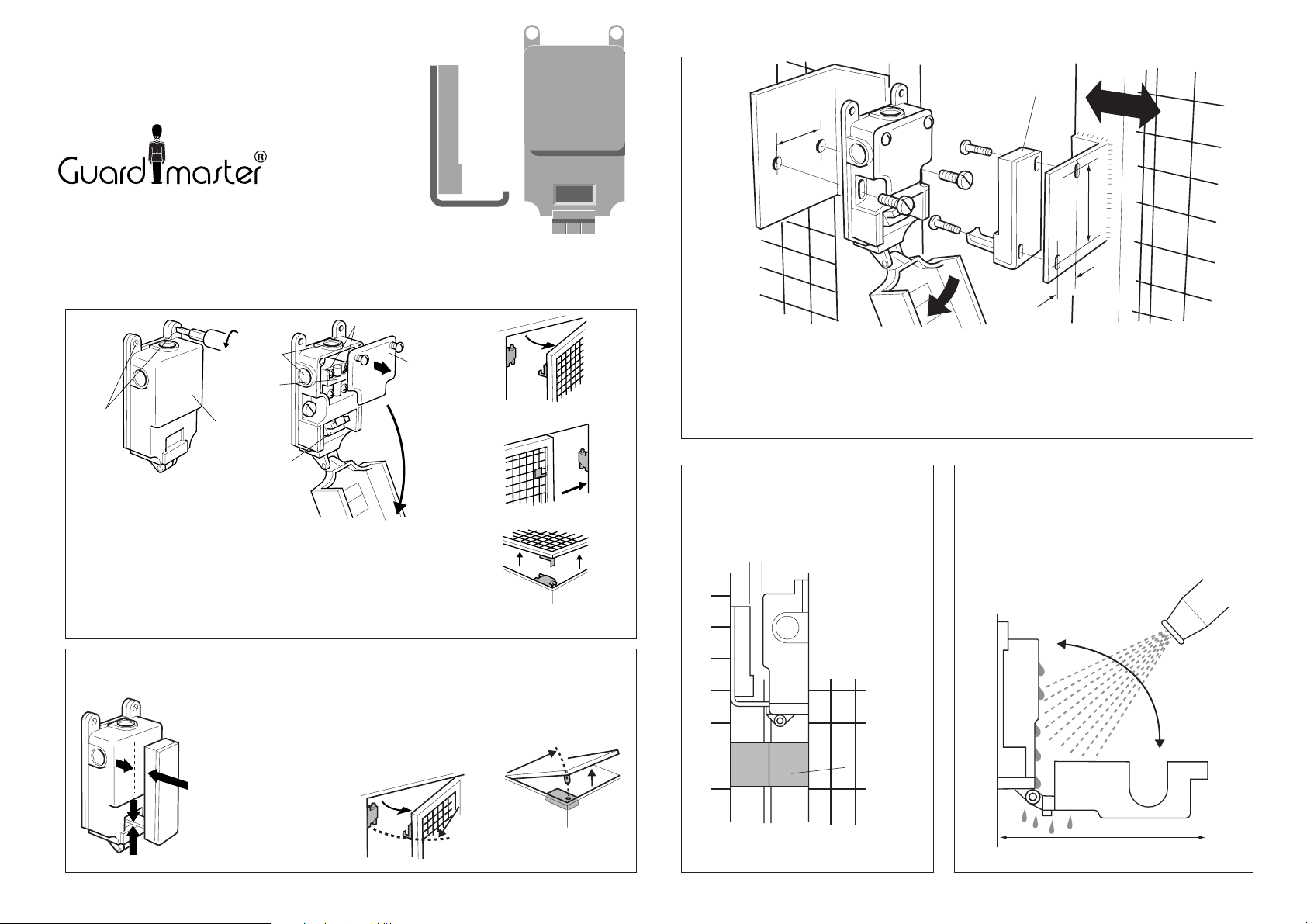
Follow steps 1 to 7 for correct installation.
Security Key
1
Cover
Retaining
Screws
The cover of the Isomag switch
hinges down to allow access to
the fixing holes. Unscrew the 2
cover retaining screws using the security key supplied and
swing down the cover. The internal plastic cover protects the
electrical contacts and the ISOMAG Insulating Barrier.
The ISOMAG 4 can be fitted in any position on hinged,
sliding or lift-off guards.
The switch will accommodate inaccuracies in the guard or door but it should not
be used as a guide. When correctly installed the bottom of the actuator tongue
2
should clear the entry hole by 1mm. When the guard is closed there should
be a gap of 3 to 6mm between the actuator and switch faces.
3 to
6mm
1mm
Coduit
Entries
Isomag
Insulating
Barrier
Cover
Operating
Cam
On hinged guards the
minimum radius from the
hinge point to the actuator
tongue centre
should be as
shown.
Safety Contacts
Actuator
Internal
Contact
Cover
Aux Contacts
Min radius
370mm
Min radius
170mm
Switch
Hinged Guards
Sliding Guards
Lift-Off Guards
3
Switch
40
Hinge down the cover to gain access to the
mounting holes. Mount the switch on the
stationary section of the guard using 2 x
M5 fixings. Use mounting brackets if
necessary.
The guard door
4
3mm MIN
6mm MAX
must be fitted
with a stop to
ensure a gap of
3 to 6mm. The
actuator MUST
NOT be allowed
to strike the
switch when the
guard door is
closed.
STOP
Actuator
M5
Mount the actuator on the moving guard
section with the actuator tongue centrally
opposite the switch entry hole. Use the
two security screws provided. The
elongated holes allow adjustment before
fully tightening the screws.
5
The switch cover can be hinged
down for high pressure hosing.
A gap of 150mm is required to allow
the switch lid to hinge down.
60.5
19.5
150mm
Page 2
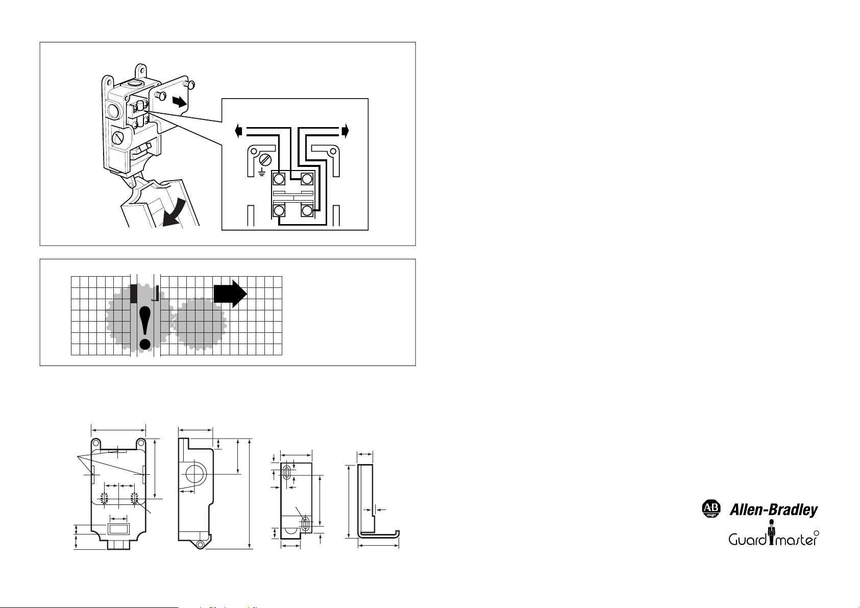
6
7
DIMENSIONS
58 38
Remove the internal cover and connect the
contact terminals as shown. Use the most
convenient of the 3 knock out conduit entry
points.
SAFETY
CIRCUIT
11
22
AUX
CIRCUIT
12
24
After installation check all of
the interlocked guard doors
to ensure that the machine is
isolated and stopped before
the guard has been opened
a sufficient distance to allow
access to the hazardous
area.
TECHNICAL SPECIFICATIONS
Safety contacts:
Safety contact gap:
Auxiliary contacts:
Switch interior:
Protection:
Mounting:
Cover screws:
Cleaning:
Operating temperature:
Operating life:
Conduit entries:
Actuator:
Double positive break, N/O, AC11 500V 1A
> 2 x 2.6mm.
Double positive break, N/C, AC11 500V 1A
Case:
Heavy duty die cast alloy, epoxy coated, colour red.
Glass reinforced nylon, self extinguishing.
IP66.
Any position.
Fixing:
2 x M5.
Resistorx anti-tamper.
May be steam cleaned or high pressure hosed.
-35°C to +80°C.
6
> 10 x 10
3 x BS20mm
Pressed steel, chrome plated. Magnet housing
moulded ABS.
2 x M4 Resistorx anti-tamper (supplied).
Fixing:
DC11 240V 0.5A
DC11 240V 0.5A
250V 2A
100V 5A
250V 2A
100V 5A
ACCESSORIES
The Isomag 4 is available with alternative PG11 conduit threads.
Spare Actuator
Stuffing Gland - BS20mm
Stuffing Gland - PG11
Conduit Beacon - Indicator light (supplied without bulb) fits in spare
conduit entry hole
Bulb for above - 24V, 110V, 240V (specify vo;tage).
Security Key
Screwdriver (inc. security key)
BS 20mm
CONDUIT
ENTRY
11.5
13.3
35.05
64.3
20 20
121.3
M5
15
5.25
10
M4
18
30
5
5.25
60.5
5.25
18
81
2
R
53
Drg no. 10506/0
 Loading...