

Page 1

Technical Data
Original Instructions
IEC Busbar Mounting System Specifications
Bulletins 141A, 141C
Top ic Pa ge
Product Overview 2
141C Crossboard® Mounting System 3
Catalog Number Explanation 3
Product Selection 4
Accessories 6
Specifications 7
Approximate Dimensions 9
141A Classic Mounting System 17
Catalog Number Explanation 17
Product Selection 19
Specifications 32
Approximate Dimensions 38
Additional Resources 55
Page 2
Product Overview
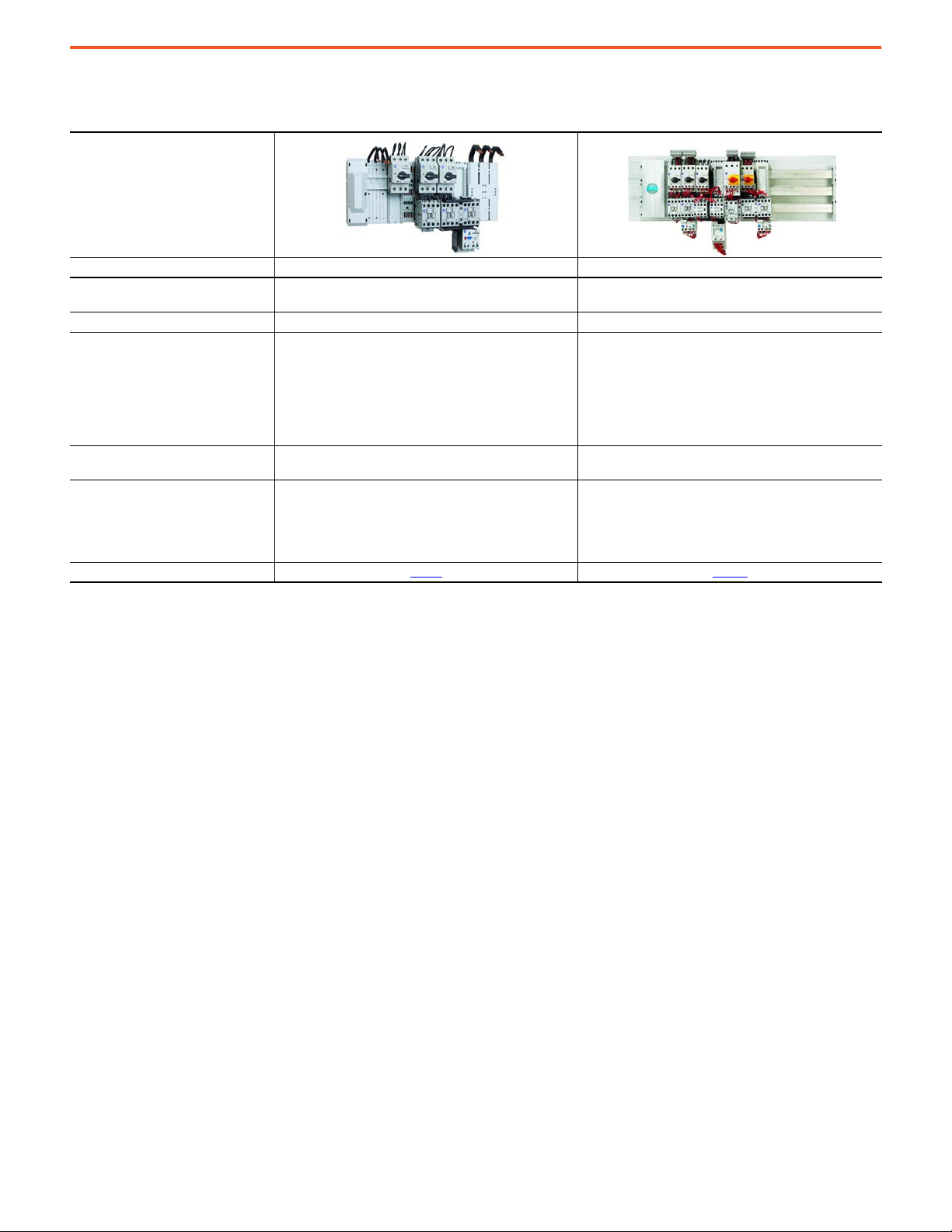
Product Overview
Bulletin No. 141C Crossboard® Mounting System 141A MCS Mounting System
Current Rating, Max.
Degree of Protection (Ingress Rating) IP20 IP20B (finger safe)
•IEC/EN 61439-1:2011
•UL 508
Standards Compliance
Certifications
Features
Product Selection page 3
(1) Most components comply with UL 508; there some exceptions. Consult your local Rockwell Automation sales office or Allen-Bradley distributor.
• CSA C22.2, No 14
•EN 60947-1 + A1:2007
•EN 60947-1 + A2:2011
• EN 60947-3 + A1:2008
• EN 60947-3 + A2:2012
• Reduced power wiring
• Efficient design with decreased panel space
• Adapters to support a wide range of devices
• Plug-and-play design
UL: 100 A
IEC: 125 A
CE
cULus Listed
•IEC/EN 61439-1
(1)
•UL 508
• CSA C22.2, No 14
• Reduced power wiring
• Efficient design with decreased panel space
• Factory-assembled starters
• Adapters to support a wide range of devices
• Plug-and-play design
UL: 1400 A
IEC: 1175 A
CE
cULus Recognized
page 17
2 Rockwell Automation Publication 141-TD001A-EN-P - April 2021
Page 3
141C Crossboard® Mounting System
Catalog Number Explanation
Examples that are given in this section are not intended to be used for product selection. Not all combinations produce a valid catalog
number.
Busbar Bases
141C – B 225
abc
abc
Bulletin Number Type Length
Code Description Code Description Code Description
141C Crossboard Mounting System B Busbar system base, 3-pole 225 225 mm (8.86 in.)
405 405 mm (15.94 in.)
Busbar Adapters
141C – 18 S 16 L1
abcde
abcde
Bulletin Number No. of Poles/Width Mounting Rail Current Rating Terminal Connection
Code Description Code Description Code Description Code Description Code Description
141C Crossboard Mounting System 18 1 pole, 18 mm (0.71 in.) S Fixed Blank
45 3 poles, 45 mm (1.77 in.) R Adjustable 16 16 A
0 A (no electrical
connection)
25 25 A L1 L1
32 32 A L2 L2
45 45 A L3 L3
63 63 A
Blank
No electrical
connection
Connection Modules
141C – VN 16
abc
abc
Bulletin Number Type Wire Size
Code Description Code Description Code Description
141C Crossboard Mounting System VN Connection module, 3-pole 16
50
16 mm2, #14…6 AWG
50 mm2, #10…1 AWG
Rockwell Automation Publication 141-TD001A-EN-P - April 2021 3
Page 4
141C Crossboard® Mounting System Product Selection
Busbar Adapters for Bulletin 140G Molded Case Circuit Breakers, 140MG Motor Protection Circuit Breakers, and 140MG Motor Circuit Protectors
141C – G G U
abcd
abcd
Bulletin Number Type Frame Size Terminals
Code Description Code Description Code Description Code Description
141C Crossboard Mounting System
Busbar adapters for Bulletin 140G and
G
MG devices
G G-Frame U Universal Connection
H H-Frame
Product Selection
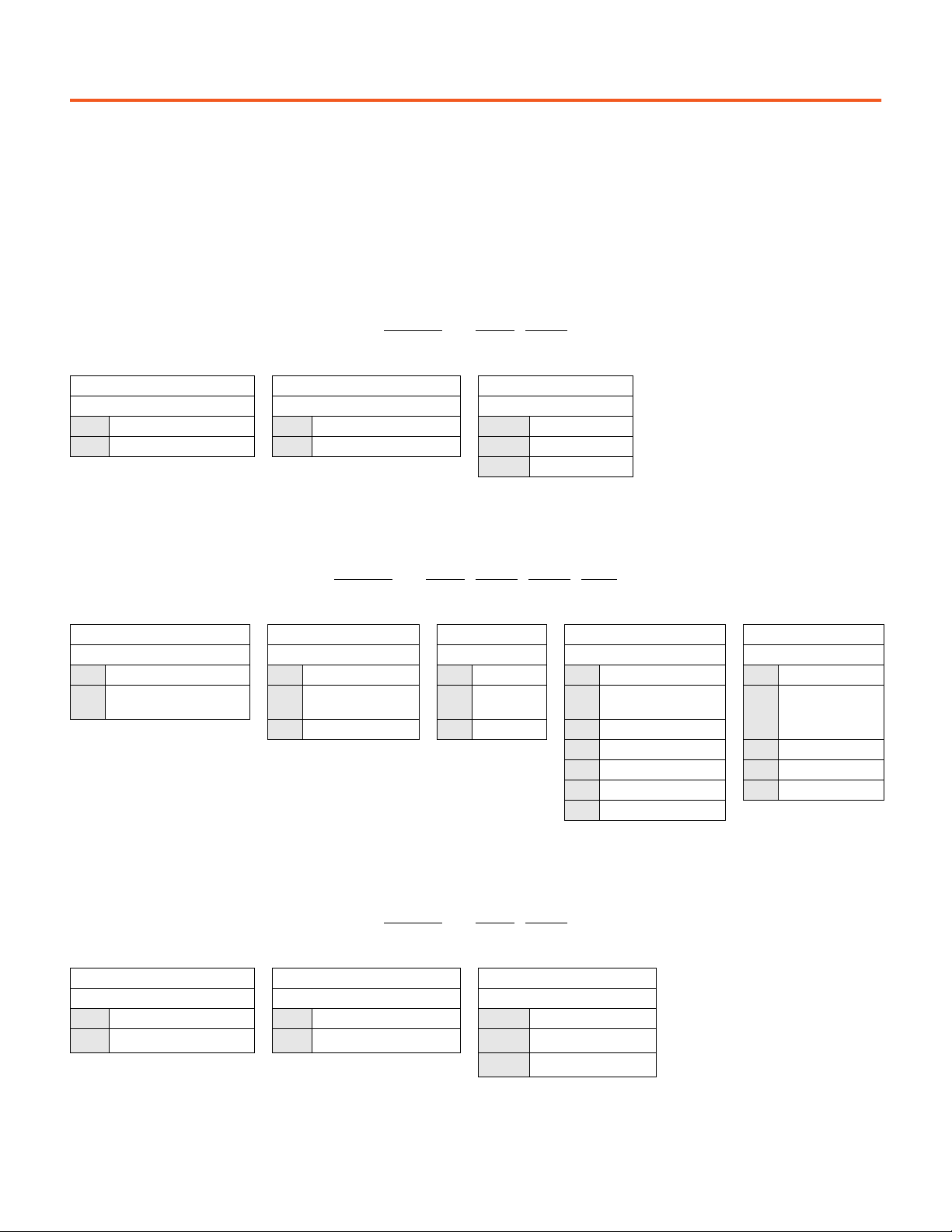
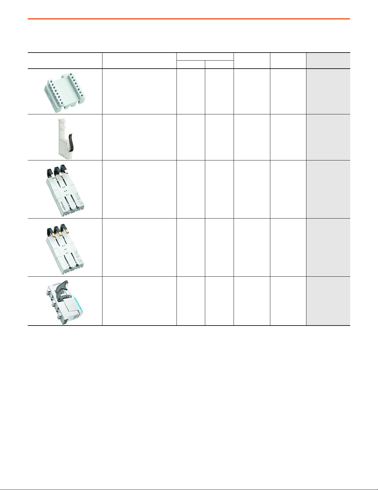
Busbar System Bases
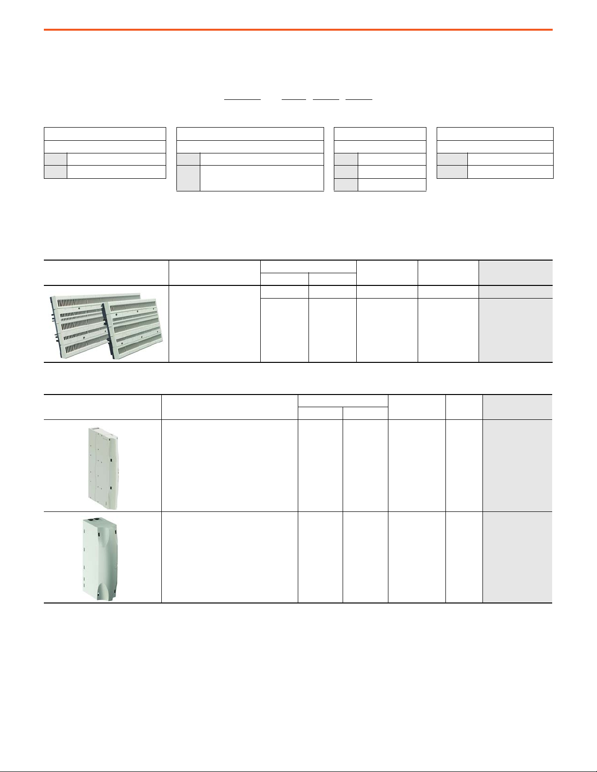
Connection Modules
Description
Busbar system base
•3 poles
Description
Connection module
•3-pole
• Spring terminals
•16 mm2, #14…6 AWG wire size
Connection module
•3-pole
• Box terminals
2
•50 mm
, #10…1 AWG wire size
Rated Thermal Current [A]
IEC UL
125 100 225 (8.86) 1
125 100 405 (15.94) 1
Rated Thermal Current [A]
IEC UL
63 48 22.5 (0.89) 1 141C-VN16
125 100 45 (1.77) 1 141C-VN50
Width [mm (in.)] Pkg. Qty. Cat. No.
Width [mm (in.)] Pkg. Qty. Cat. No.
141C-B225
141C-B405
4 Rockwell Automation Publication 141-TD001A-EN-P - April 2021
Page 5
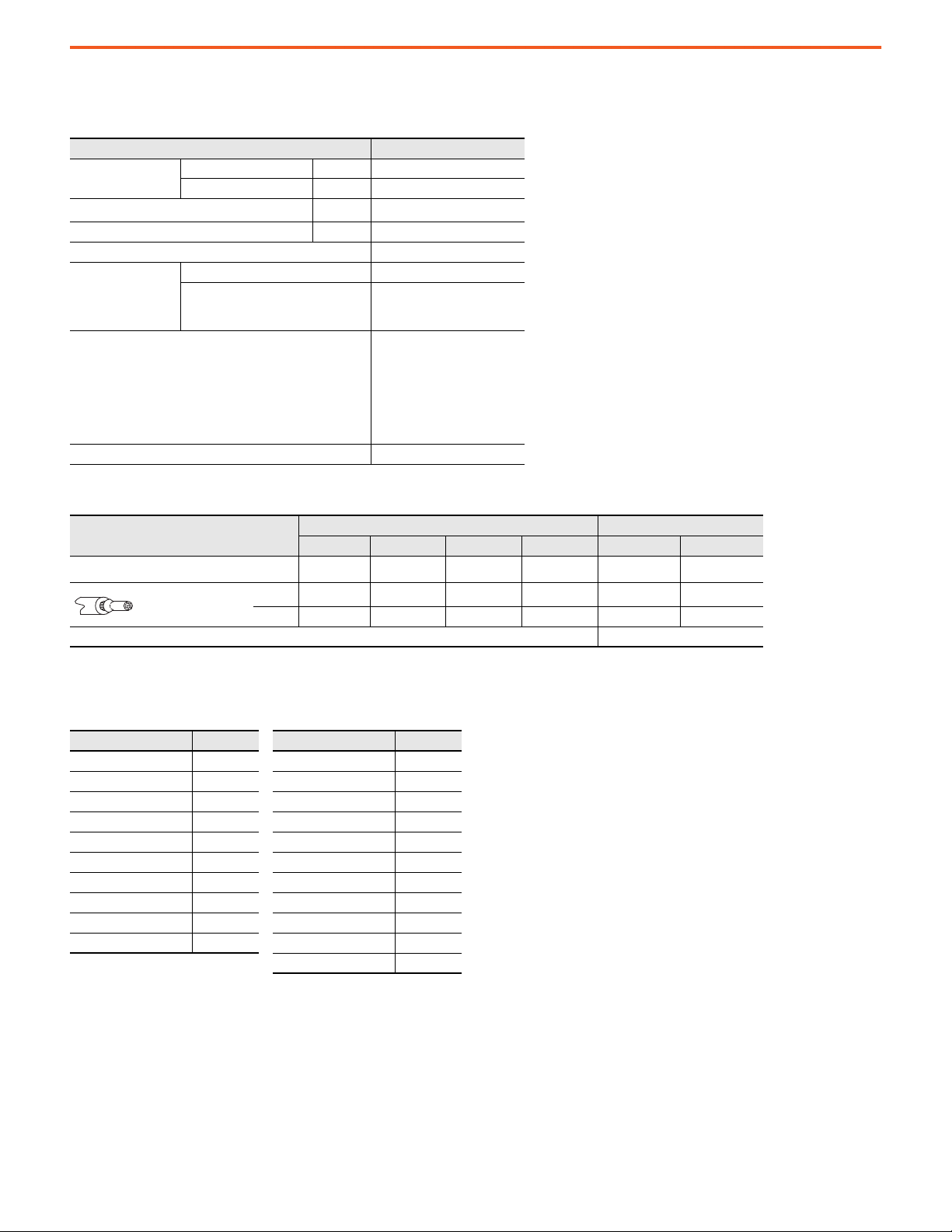
Adapters, 3 Poles
141C Crossboard® Mounting System Product Selection
Adapters, 1 Pole
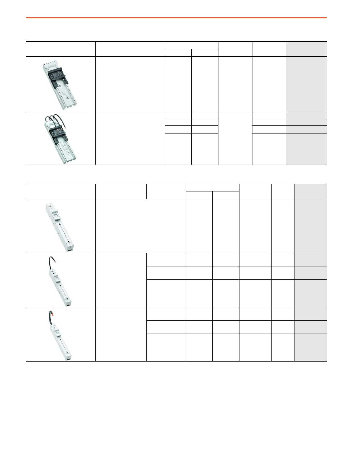
Description
3-Pole Adapter
• without electrical connection
• 1 adjustable mounting rail
3-Pole Adapter
• 1 adjustable mounting rail
Description Connection
Rated Thermal Current [A]
IEC UL
— — 45 (1.77) 1
16 12
25 25 1 141C-45R25
32 30 1
45 45 1 141C-45R45
Rated Thermal Current [A]
IEC UL
Width [mm (in.)] Pkg. Qty. Cat. No.
1 141C-45R16
45 (1.77)
Width
[mm (in.)]
Pkg. Qty. Cat. No.
141C-45R
141C-45R32
1-Pole Adapter
• without electrical connection
• 1 adjustable mounting rail
1-Pole Adapter
•#14 AWG wires
• 1 fixed mounting rail
• White indicator shows
which pole is active
1-Pole Adapter
•#8 AWG wires
• 1 fixed mounting rail
• White indicator shows
which pole is active
•L1
•Top busbar
•L2
•Middle busbar
•L3
• Bottom busbar
•L1
•Top busbar
•L2
•Middle busbar
•L3
• Bottom busbar
——18 (0.71)6
16 16 18 (0.71) 6
16 16 18 (0.71) 6 141C-18S16L2
16 16 18 (0.71) 6
63 63 18 (0.71) 6 141C-18S63L1
63 63 18 (0.71) 6
63 63 18 (0.71) 6 141C-18S63L3
141C-18S
141C-18S16L1
141C-18S16L3
141C-18S63L2
Rockwell Automation Publication 141-TD001A-EN-P - April 2021 5
Page 6
141C Crossboard® Mounting System Accessories
Accessories
Description
Adapter Extension Module
• For 45 mm adapters
Fuse Holder
• For 10 x 38 and Class CC fuses
•3-pole
• 1 fixed mounting rail
Breaker Adapter
• For 140G-G Molded Case Circuit
Breaker (MCCB)
• Universal Terminals for Top or
Bottom Mount
Rated Thermal Current [A]
IEC UL
— — 45 (1.77) 8
16 12.5 22.5 (0.89) 1
160 100 90 (3.54) 1
Width [mm (in.)] Pkg. Qty. Cat. No.
141C-X40
141C-23S16F
141C-GGU
Breaker Adapter
•For 140G-H MCCB
• Universal Terminals for Top or
Bottom Mount
Fused Switch Disconnector 125 49.5 (1.95) 1
160 100 90 (3.54) 1
141C-GHU
141C-NFD125
6 Rockwell Automation Publication 141-TD001A-EN-P - April 2021
Page 7

Specifications
Table 1 - Short-circuit Current Rating (SCCR)
141C Crossboard® Mounting System Specifications
Cat. No. Description Rating SCCR [kA]
10 kA 600V — None (3-cycle)
141C-B225 Busbar base, 225 mm (8.86 in.) 600V/100 A
141C-B405 Busbar base, 405 mm (15.94 in.) 600V/100 A
141C-VN16 Connection module, 22.5 mm (0.89 in.) 600V/48 A
141C-VN50 Connection module, 45 mm (1.77 in.) 600V/100 A
141C-18S16L1
141C-18S16L2
141C-18S16L3
141C-18S63L1
141C-18S63L2
141C-18S63L3
141C-45R16 Busbar adapter, 3-pole, 45 mm (1.77 in.) 600V/12 A
141C-45R25 Busbar adapter, 3-pole, 45 mm (1.77 in.) 600V/25 A
141C-45R32 Busbar adapter, 3-pole, 45 mm (1.77 in.) 600V/30 A
141C-45R45 Busbar adapter, 3-pole, 45 mm (1.77 in.) 600V/45 A
141C-GGU
141C-GHU
Busbar adapter, 1-pole, 18 mm (0.71 in.) 600V/16 A
Busbar adapter, 1-pole, 18 mm (0.71 in.) 600V/63 A
Busbar adapter, 3-pole, 90 mm (3.54 in.) 600V/125 A
100 kA 480V 125 A Circuit breaker (DIVQ)
65 kA 600V 125 A Circuit breaker (DIVQ)
100 kA 600V 175 A Fuse (Class J)
10 kA 600V — None (3-cycle)
100 kA 480V 125 A Circuit breaker (DIVQ)
65 kA 600V 125 A Circuit breaker (DIVQ)
100 kA 600V 175 A Fuse (Class J)
6 kA 600V — None (3-cycle)
50 kA 600V 50 A Fuse (Class J)
10 kA 600V — None (3-cycle)
100 kA 480V 125 A Circuit breaker (DIVQ)
65 kA 600V 125 A Circuit breaker (DIVQ)
100 kA 600V 175 A Fuse (Class J)
6 kA 600V — None (3-cycle)
50 kA 600V 20 A Fuse (Class CC)
14 kA 480/277V 20 A Circuit breaker (DIVQ)
65 kA 480/277V 16 A NKJH type E
6 kA 600V — None (3-cycle)
10 kA 480/277V 30 A Circuit breaker (DIVQ)
65 kA 480/277V 65 A NKJH type E
5 kA 600V — None (3-cycle)
50 kA 600V 20 A Fuse (Class CC)
65 kA 480V 12 A NKJH type E
5 kA 600V — None (3-cycle)
65 kA 480V 32 A NKJH type E
5 kA 600V — None (3-cycle)
65 kA 480V 32 A NKJH type E
6 kA 600V — None (3-cycle)
65 kA 480V 55 A NKJH type E
10 kA 600V — None (3-cycle)
100 kA 480V 125 A Circuit breaker (DIVQ)
42 kA 600V 125 A Circuit breaker (DIVQ)
Protection
Vol tag e Cu rren t Typ e
Rockwell Automation Publication 141-TD001A-EN-P - April 2021 7
Page 8
141C Crossboard® Mounting System Specifications
General Data
Table 2 - Main Circuits
Attribute Value
Rated insulation
voltage U
i
Rated impulse withstand voltage U
Rated frequency [Hz] 50…60
Pollution degree 2
Protection class
Standards Compliance
Certifications CE, cULus Listed
IEC, EN [V] 690
UL, CSA [V] 600
imp
Adapters and busbars IP00
Adapters and busbars mounted on
plate, connected conductors, and
usage of busbar covers
[kV] 6
•IEC/EN 61439-1:2011
•UL 508
• CSA C22.2, No 14
• EN 60947-1 + A1:2007
• EN 60947-1 + A2:2011
•EN 60947-3 + A1:2008
•EN 60947-3 + A2:2012
IP20
Table 3 - Adapter Data
3-Pole Adapters 1-Pole Adapters
141C-45R16 141C-45R25 141C-45R32 141C-45R45 141C-18S16… 141C-18S63…
Rated current at 60 °C I
Flexible with ferrule
Insulation rating of conductors 105 °C (221 °F) 105 °C (221 °F)
(1) The admissible load of a complete system depends on the system topography and the application parameters. Factors of influence are ambient temperature, air
circulation, busbar load, distribution of busbar load, mix of adapters and switchgear components.
(1)
th
[A] 16 25 32 45 16 63
2
[mm
[AWG] 14 12 10 8 14 8
2.5 4 6 10 2.5 10
]
Table 4 - Weights
Cat. No. Weight [g] Cat. No. Weight [g]
141C-VN16 182 141C-18S 44
141C-VN20 272 141C-45R 89
141C-B225 765 141C-45R16 109
141C-B405 1326 141C-45R25 117
141C-18S16L1 51 141C-45R32 124
141C-18S16L2 51 141C-GGU 519
141C-18S16L3 51 141C-GHU 519
141C-18S63L1 72 141C-45R45 150
141C-18S63L2 72 141C-X40 18
141C-18S63L3 72 141C-NFD125 422
141C-23S16F 92
8 Rockwell Automation Publication 141-TD001A-EN-P - April 2021
Page 9
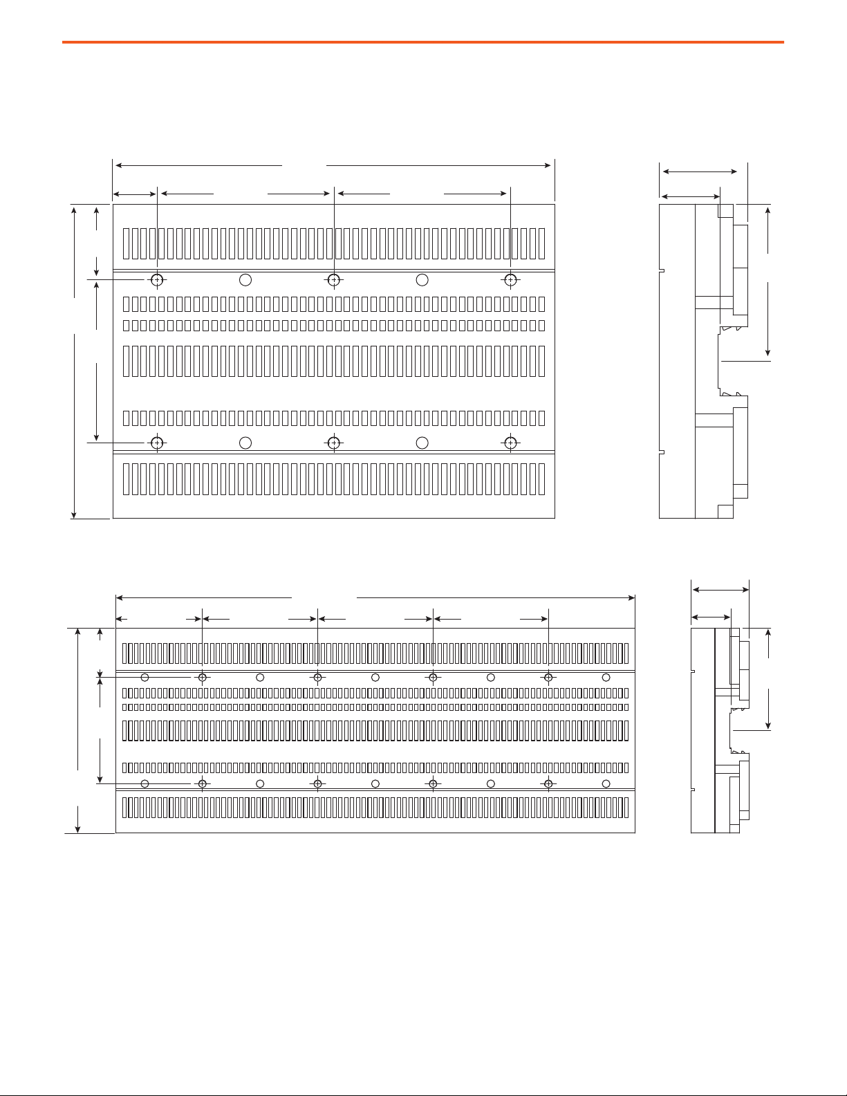
141C Crossboard® Mounting System Approximate Dimensions
160.0
(6.3)
83
(3.27)
90.0 (3.54)
45.1 (1.78)
80
(3.15)
30.9 (1.22)
38.5
(1.52)
22.5
(0.89)
225 (8.86)
90.0 (3.54)
160.0
(6.3)
83
(3.27)
38.5
(1.52)
67.5 (2.66) 90.0 (3.54)
405 (15.94)
90.0 (3.54) 90.0 (3.54)
45.1
(1.78)
80
(3.15)
30.9
(1.22)
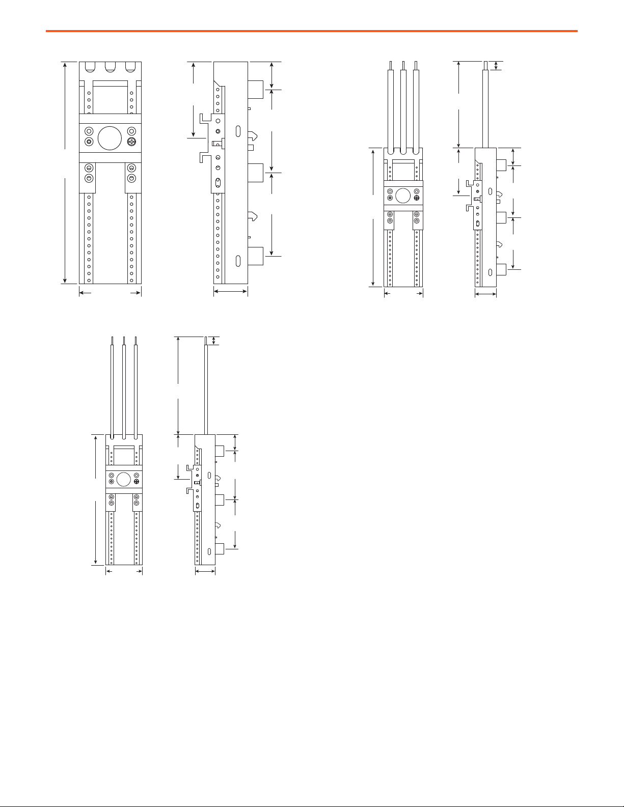
Approximate Dimensions
Dimensions are in millimeters (inches.) and are not intended to be used for manufacturing purposes.
Figure 1 - Cat. No. 141C-B225 Busbar System Base
Figure 2 - Cat. No. 141C-B405 Busbar System Base
Rockwell Automation Publication 141-TD001A-EN-P - April 2021 9
Page 10
141C Crossboard® Mounting System Approximate Dimensions
20.0
(0.79)
60.0
(2.36)
60.0
(2.36)
160.0
(6.3)
99.0 (3.9)
22.1
(0.87)
110.0 (4.33)
20.0
(0.79)
60.0
(2.36)
60.0
(2.36)
160.0
(6.3)
81.5 (3.21)
45.0 (1.77)
92.5 (3.64)
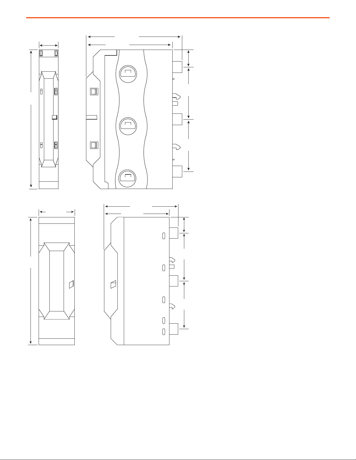
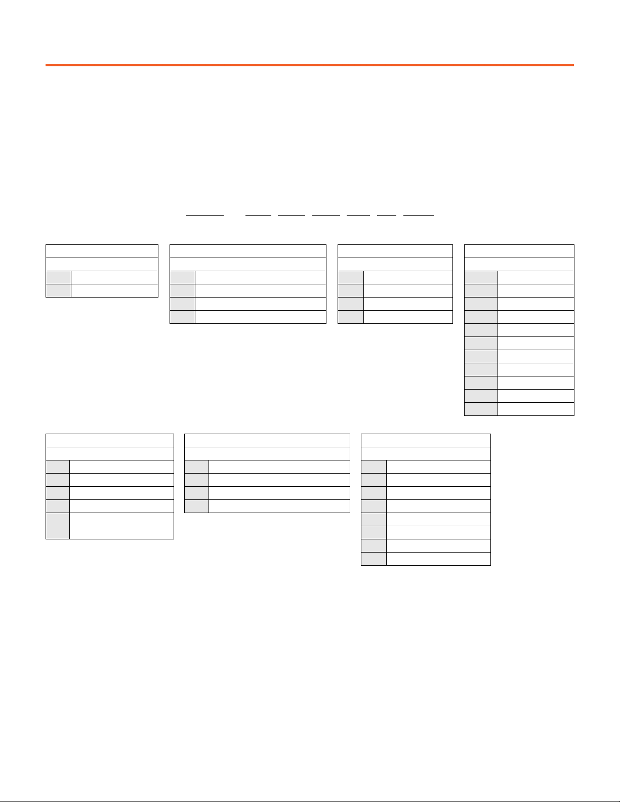
Figure 3 - Cat. No. 141C-VN16 Connection Module with Spring Terminals
Figure 4 - Cat. No. 141C-VN50 Connection Module with Box Terminals
10 Rockwell Automation Publication 141-TD001A-EN-P - April 2021
Page 11
141C Crossboard® Mounting System Approximate Dimensions
160.0
(6.3)
45.0 (1.77)
20.0
(0.79)
60.0
(2.36)
60.0
(2.36)
55
(2.17)
24.5
(0.96)
160.0
(6.3)
45.0 (1.77)
20.0
(0.79)
60.0
(2.36)
60.0
(2.36)
55
(2.17)
24.5
(0.96)
120.0
(4.72)
10.0 (0.39)
Figure 5 - Cat. No. 141C-45R 3-Pole Adapter
Figure 6 - Cat. No. 141C-45R16 3-Pole Adapter
Figure 7 - Cat. No. 141C-R25, -R32, and -R45 3-Pole Adapters
10.0 (0.39)
100.0
(3.94)
20.0
60.0
(2.36)
60.0
(2.36)
(0.79)
160.0
(6.3)
45.0 (1.77)
55
(2.17)
24.5
(0.96)
Rockwell Automation Publication 141-TD001A-EN-P - April 2021 11
Page 12
141C Crossboard® Mounting System Approximate Dimensions
45.1 (1.78) 24.5 (0.96)
46.0
(1.81)
39.8
(1.57)
160.0
(6.3)
60.0
(2.36)
20.0
(0.79)
22.3
(0.88)
60.0
(2.36)
22.5
(0.89)
62.5
(2.46)
75.0 (2.95)130.9 (5.15)
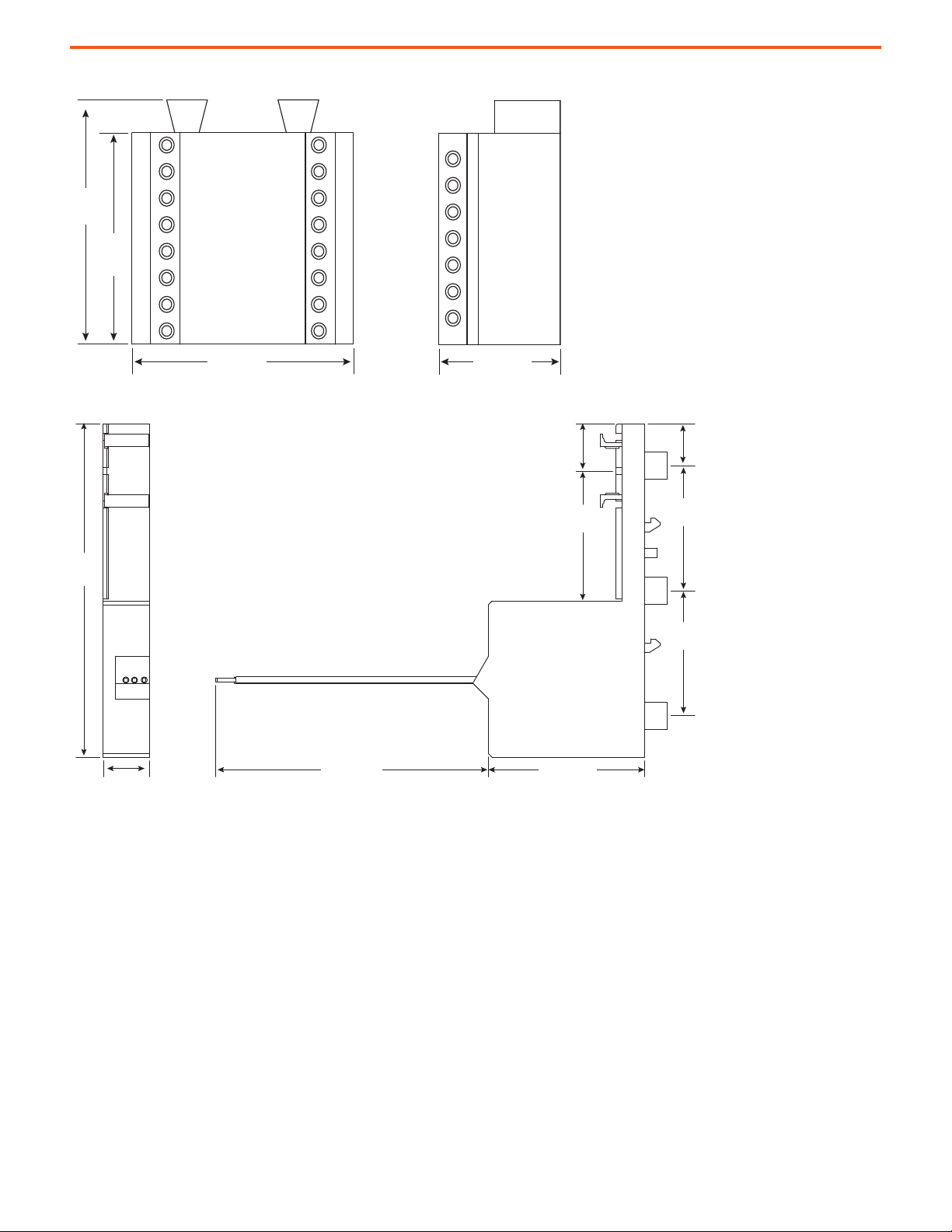
Figure 8 - Cat. No. 141C-X40 Adapter Extension Module
Figure 9 - Cat. No. 141C-23S16F Fuse Holder
12 Rockwell Automation Publication 141-TD001A-EN-P - April 2021
Page 13
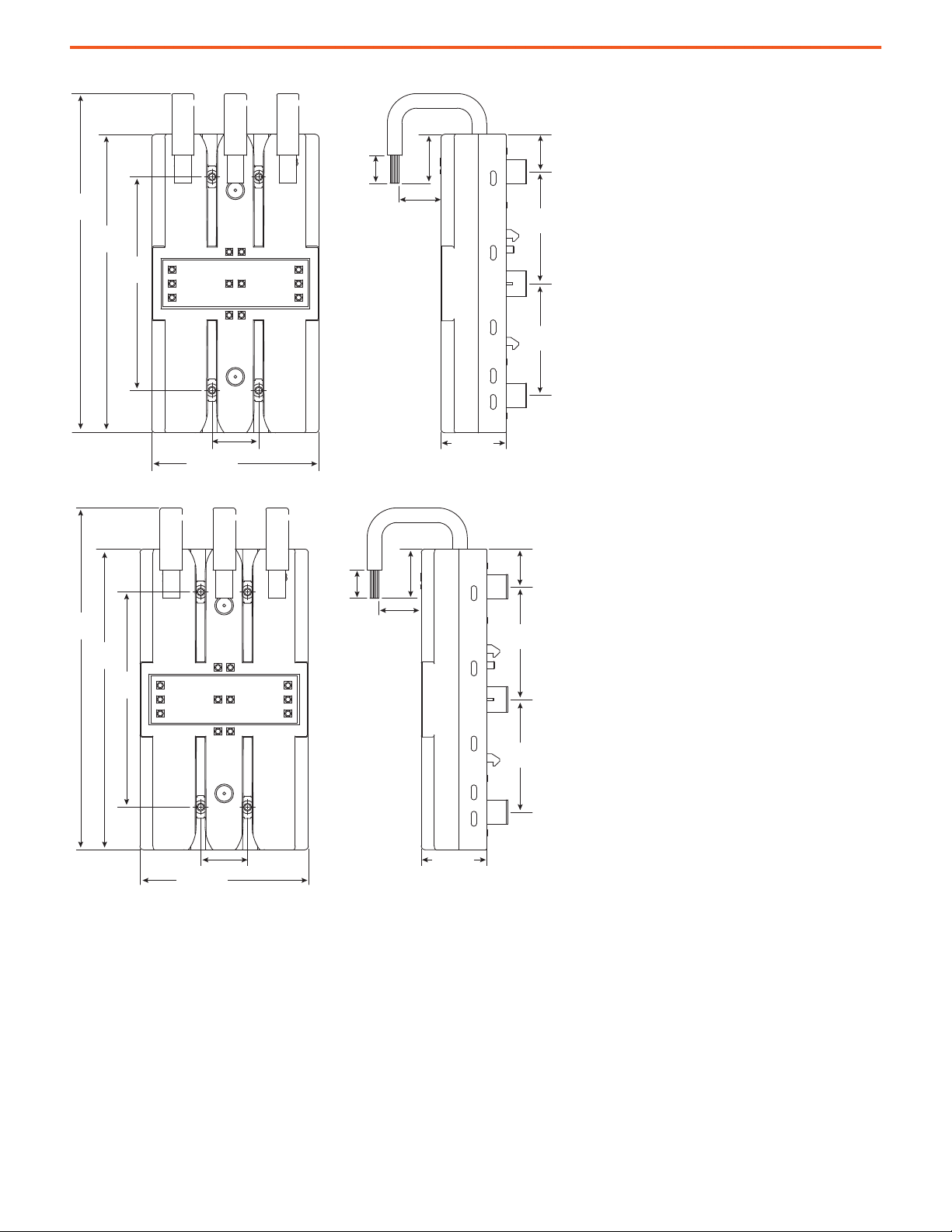
Figure 10 - Cat. No. 141C-GGU Breaker Adapter
25.0 (0.98)
20.0
(0.79)
60.0
(2.36)
60.0
(2.36)
160.0
(6.3)
90.0 (3.54)
22.6
(0.89)
35.0 (1.38)
181.9
(7.16)
114.5
(4.51)
26.2
(1.03)
15.0
(0.59)
30.0 (1.18)
20.0
(0.79)
60.0
(2.36)
60.0
(2.36)
160.0
(6.3)
90.0 (3.54)
22.6
(0.89)
35.0 (1.38)
181.9
(7.16)
114.5
(4.51)
26.2
(1.03)
15.0
(0.59)
141C Crossboard® Mounting System Approximate Dimensions
Figure 11 - Cat. No. 141C-GHU Breaker Adapter
Rockwell Automation Publication 141-TD001A-EN-P - April 2021 13
Page 14
141C Crossboard® Mounting System Approximate Dimensions
160.0
(6.3)
18.0
(0.71)
20.0
(0.79)
55
(2.17)
60.0
(2.36)
60.0
(2.36)
25.0
(0.98)
160.0
(6.3)
18.0
(0.71)
25.0
(0.98)
20.0
(0.79)
60.0
(2.36)
60.0
(2.36)
55
(2.17)
100.0
(3.94)
10.0 (0.39)
160.0
(6.3)
18.0
(0.71)
25.0
(0.98)
20.0
(0.79)
60.0
(2.36)
60.0
(2.36)
55
(2.17)
100.0
(3.94)
10.0 (0.39)
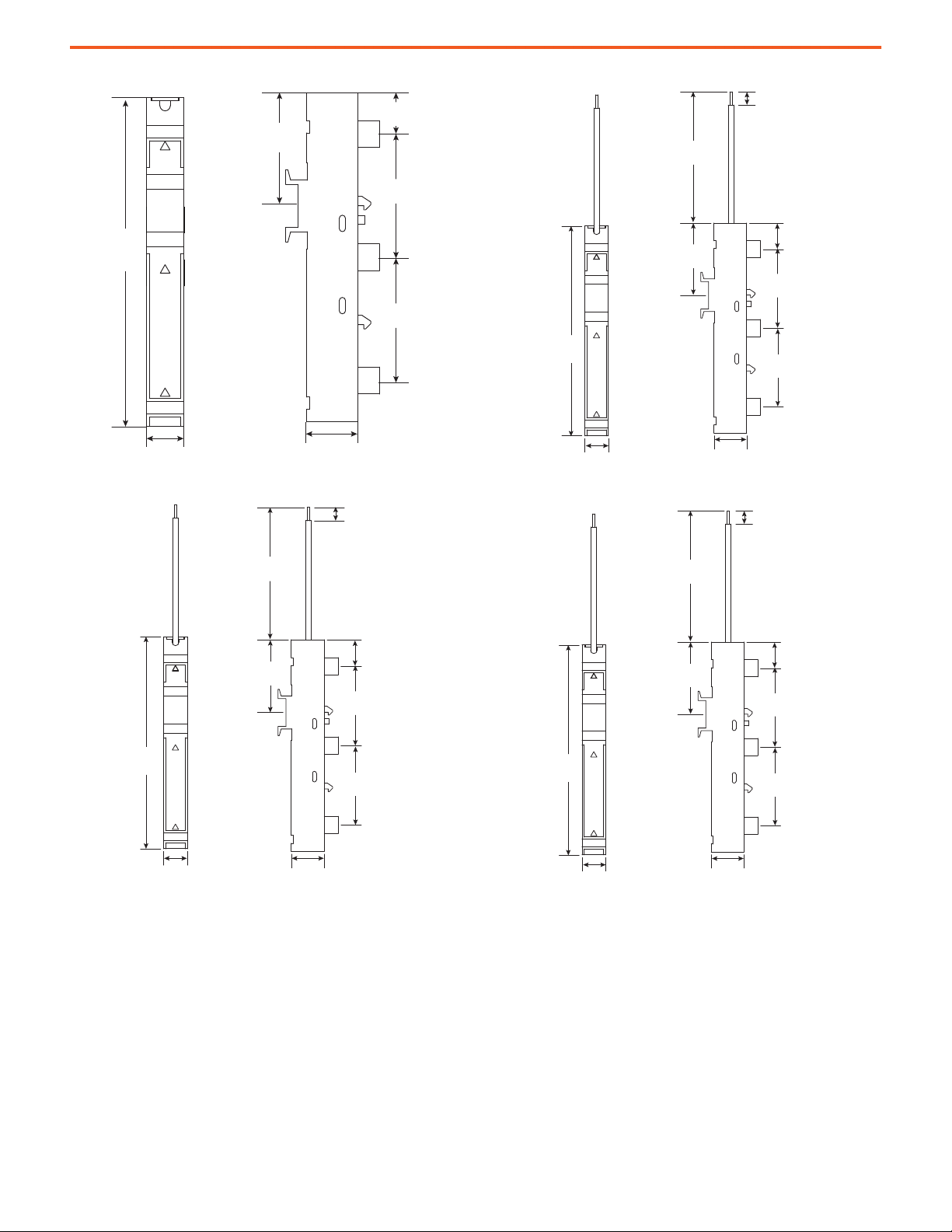
Figure 12 - Cat. No. 141C-18S 1-Pole Adapter
Figure 13 - Cat. No. 141C-181S6L1 1-Pole Adapter
Figure 14 - Cat. No. 141C-18S16L2 1-Pole Adapter
Figure 15 - Cat. No. 141C-18S16L3 1-Pole Adapter
10.0 (0.39)
160.0
(6.3)
18.0
(0.71)
60.0
(2.36)
55
(2.17)
25.0
(0.98)
60.0
(2.36)
60.0
(2.36)
20.0
(0.79)
14 Rockwell Automation Publication 141-TD001A-EN-P - April 2021
Page 15
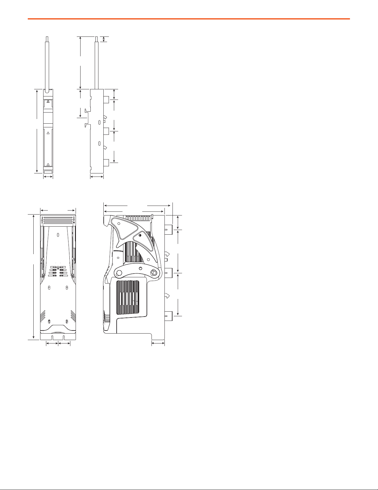
Figure 16 - Cat. No. 141C-18S63L1, -L2, and -L3 1-Pole Adapters
20.0
(0.79)
60.0
(2.36)
60.0
(2.36)
18.0
(0.71)
16.6
(0.65)
49.5 (1.95)
174.5
(6.87)
16.6
(0.65)
85.0 (3.35)
95.8 (3.77)
10.0 (0.39)
100.0
(3.94)
20.0
60.0
(2.36)
60.0
(2.36)
(0.79)
160.0
(6.3)
55
(2.17)
141C Crossboard® Mounting System Approximate Dimensions
18.0
(0.71)
25.0
(0.98)
Figure 17 - Cat. No. NFD125 Fuse Switch Disconnector
Rockwell Automation Publication 141-TD001A-EN-P - April 2021 15
Page 16

141C Crossboard® Mounting System Approximate Dimensions
Notes:
16 Rockwell Automation Publication 141-TD001A-EN-P - April 2021
Page 17
141A Classic Mounting System
Catalog Number Explanation
Examples that are given in this section are not intended to be used for product selection. Not all combinations produce a valid catalog
number.
Busbar Adapters
141A – C S 45 R R 16
abcdefg
ab cd
Bulletin Number Type Length Width
Code Description Code Description Code Description Code Description
141A Classic Mounting System G Standard busbar adapter S Short: 200 mm (7.87 in.) 45 45 mm (1.77 in.)
F Standard busbar adapter with terminals M Medium: 260 mm (10.2 in.) 54 54 mm (2.13 in.)
C Compact busbar adapter L Long: 320 mm (12.6 in.) 63 63 mm (2.48 in.)
72 72 mm (2.83 in.)
81 81 mm (3.19 in.)
90 90 mm (3.54 in.)
108 108 mm (4.25 in.)
110 110 mm (4.33 in.)
180 180 mm (7.09 in.)
270 270 mm (10.63 in.)
efg
Top Hat Rail Bottom Hat Rail Current Rating
Code Description Code Description Code Description
R Plastic hat rail R Rockwell Automation custom plastic rail Blank 0 A (no electrical connection)
S Plastic hat rail S Standard plastic rail 16 16 A
M Metal hat rail Blank No bottom rail 25 32 A
Screw mounting, variable
V
positions
45 63 A
125 125 A
200 200 A
250 250 A
Rockwell Automation Publication 141-TD001A-EN-P - April 2021 17
Page 18

141A Classic Mounting System Catalog Number Explanation
Iso (Isolation) Busbar Adapters
141A – S M 45 R S 25
abcdefg
abcd
Bulletin Number Type Length Width
Code Description Code Description Code Description Code Description
141A Classic Mounting System S Iso busbar adapter S Short: 200 mm (7.87 in.) 45 45 mm (1.77 in.)
M Medium: 260 mm (10.2 in.) 54 54 mm (2.13 in.)
63 63 mm (2.48 in.)
ef g
Top Hat Rail Bottom Hat Rail Current Rating
Code Description Code Description Code Description
R Plastic hat rail R Plastic hat rail Blank 0 A (no electrical connection)
S Plastic hat rail S Plastic hat rail
25
45 45 A
Width "c" 45 mm (1.77 in.) = 25 A
Width "c" 54 mm (2.13 in.) = 32 A
Busbar Adapters for Bulletin 140G Molded Case Circuit Breakers, 140MG Motor Protection Circuit Breakers, and 140MG Motor Circuit Protectors
141A – G H T
abcd
ab cd
Bulletin Number Type Length Width
Code Description Code Description Code Description Code Description
141A Classic Mounting System
Busbar adapters for Bulletin 140G
G
and MG devices
H Frame size G, Frame size H T Top Connection
J Frame size J B Bottom Connection
K Frame size K U Universal Connection
M Frame size M
Panel Mounting Modules
141A – W M 45 R R
abcdef
ab c def
Bulletin Number Type Length Width Top Hat Rail Bottom Hat Rail
Code Description Code Description Code Description Code Description Code Description Code Description
Classic Mounting
141A
System
W
Panel mounting
module
S Short: 200 mm (7.87 in.) 45 45 mm (1.77 in.) R Plastic hat rail R Plastic hat rail
M Medium: 260 mm (10.2 in.) 54 54 mm (2.13 in.)
L Long: 320 mm (12.6 in.)
18 Rockwell Automation Publication 141-TD001A-EN-P - April 2021
Page 19

141A Classic Mounting System Product Selection
Product Selection
Iso Busbar Adapters
• Two-part construction
- Device Adapter Plate (DAP) (carrying the starter) snaps onto the base adapter
- Base adapter remains on busbar when exchanging starters, providing isolation from live parts
• Test position with load circuit isolated
• Optional control plug makes the starter fully pluggable
• Adapters with assigned current ratings supply the load current to the starter/load feeder by means of wire connections
• Multiple adapters can be combined to bigger platforms by use of the connection clips
• Fits on 5 mm (0.19 in.) or 10 mm (0.39 in.) thick busbars
• Meets UL 508A feeder circuit spacing requirements
Description
Iso Busbar Adapters with Wires - Short Length
• Wires on Device Adapter Plates for electrical
connection
Iso Busbar Adapters without Wires - Short Length
• Two connection clips included
Iso Busbar Adapters with Wires - Medium Length
• Wires on Device Adapter Plates for electrical
connection
Iso Busbar Adapters without Wires - Medium Length
• Two connection clips included
(1) Iso Busbar Adapters without electrical connections include two connection clips. They are intended to form bigger platforms, for example: reversing starters, starters with Smart Motor
Controllers or PowerFlex® drives.
(1)
(1)
Rated Thermal
Current I
th
25 45 (1.77)
32 54 (2.13)
45 54 (2.13) 141A-SS54RR45
45 63 (2.48)
Without
electrical
connections
25 45 (1.77)
32 54 (2.13)
45 54 (2.13)
45 63 (2.48) 141A-SM63RS45
Without
electrical
connections
[A]
Width
[mm (in.)]
45 (1.77)
54 (2.13)
45 (1.77)
54 (2.13)
63 (2.48)
Length
[mm (in.)]
200 (7.87) 2 1
200 (7.87) 1 1
260 2 1
260 1 1
Rails Pkg. Qty.
Cat. No.
141A-SS45RR25
141A-SS54RR25
141A-SS63RR45
141A-SS45R
141A-SS54R
141A-SM45RS25
141A-SM54RS25
141A-SM54RS45
141A-SM45S
141A-SM54S
141A-SM63S
Rockwell Automation Publication 141-TD001A-EN-P - April 2021 19
Page 20

141A Classic Mounting System Product Selection
Standard Busbar Adapters
• Adapters plug directly onto the busbar
• Suitable for use with control plug
• Adapters with assigned current ratings supply the load current to the starter/load feeder by means of wire connections
• Multiple adapters can be combined to bigger platforms by use of the connection clips
• Fits on 5 mm (0.19 in.) or 10 mm (0.39 in.) thick busbars
• Meets UL 508A feeder circuit spacing requirements
Description
Standard Busbar Adapters with Wires - Short Length
• Wires for electrical connection
Standard Busbar Adapters with Flexible Busbar
Connectors - Short Length
•Metal Hat Rail
• For starters with 140MG-G/-H circuit protectors
Standard Busbar Adapters without Wires — Short
Length
• Two connection clips included
Standard Busbar Adapters with Wires — Medium
Length
• Wires for electrical connection
Standard Busbar Adapters without Wires — Medium
Length
• Two connection clips included
(2)
(2)
Rated Thermal
Current I
125 (160
Without electrical
connections
Without electrical
connections
Width
[A]
[mm (in.)]
th
16
32
63
32
63
45 (1.77)
54 (2.13)
45 (1.77) 141A-GS45RR25
54 (2.13)
54 (2.13)
63 (2.48) 141A-GS63RR45
81 (3.19)
180 (7.09)
(1)
)
270 (10.63)
45 (1.77)
54 (2.13) 141A-GS54R
72 (2.83)
81 (3.19)
45 (1.77)
54 (2.13)
54 (2.13)
63 (2.48)
45 (1.77)
54 (2.13)
63 (2.48)
Length
[mm (in.)]
200 (7.87) 2
200 (7.87) 1
200 (7.87) 1
260 (10.23) 2
260 (10.23) 1
Rails Pkg. Qty.
Cat. No.
141A-GS45RR16
141A-GS54RR16
141A-GS54RR25
141A-GS54RR45
1
1
141A-GS81SS63
141A-GS180M125
141A-GS270M125
141A-GS45R
141A-GS72S
141A-GS81S
141A-GM45RS25
141A-GM54RS25
141A-GM54RS45
141A-GM63RS45
141A-GM45S
141A-GM54S
141A-GM63S
(1) IEC Rating = 160 A
(2) Standard Busbar Adapters without electrical connections include two connection clips. They are intended to form bigger platforms; for example: for reversing starters, starters with Smart
Motor Controllers or PowerFlex drives.
20 Rockwell Automation Publication 141-TD001A-EN-P - April 2021
Page 21

141A Classic Mounting System Product Selection
Standard Busbar Adapters with Terminals
• Adapters plug directly onto the busbar
• Adapters ≤ 81 mm (3.19 in.) wide can be combined to bigger platforms by use of the connection clips
• Fits on 5 mm (0.19 in.) or 10 mm (0.39 in.) thick busbars
• Meets UL 508A feeder circuit spacing requirements
Description
Rated Thermal
Current I
th
(1)
25
Standard Busbar Adapters with Terminals
•Short Length
• With terminals for electrical connection
(2)
80
(1)
25
Standard Busbar Adapters with Terminals
• Medium Length
• With terminals for electrical connection
(2)
80
Standard Busbar Adapter with Terminals on Top
• With box terminals on top for electrical connection
• Wire size: 70 mm
2
(2/0 AWG)
200 108 (4.25) 222 (8.74)
• Universal mounting capability with sliding pocket nuts (M4)
Standard Busbar Adapter with Terminals on Top
• With box terminals on top for electrical connection
• Wire size: 120 mm2 (250 MCM)
250 110 (4.33) 320 (12.6)
• Universal mounting capability with sliding pocket nuts (M4)
(1) Terminal size: 6 mm2 (10 AWG). Requires a Cat. No. 141A-FTS25 spacing adapter for UL 508A applications.
(2) Terminal size: 16 mm2 (6 AWG). Requires a Cat. No. 141A-FTS63 spacing adapter for UL 508A applications.
[A]
Width
[mm (in.)]
Length
[mm (in.)]
Rails Pkg. Qty.
45 (1.77)
54 (2.13) 141A-FS54S63
63 (2.48) 141A-FS63S63
200 (7.87) 1
72 (2.83)
81 (3.19)
45 (1.77)
1
54 (2.13) 141A-FM54SS63
63 (2.48)
260 (10.23) 2
72 (2.83) 141A-FM72SS63
81 (3.19) 141A-FM81SS63
— 1
Cat. No.
141A-FS45S25
141A-FS72S63
141A-FS81S63
141A-FM45SS25
141A-FM63SS63
141A-FS108V200T
141A-FL110V250T
Busbar Adapters for Circuit Breakers
Description For Use With
Standard Busbar Adapters with Flexible
Connecting Bars for Electrical Connection
• Meets UL 508A feeder circuit spacing
requirements
– Terminal lugs for circuit breaker 140G-_-TL*
required, sold separately
Standard Busbar Adapters with Flexible
Connecting Bars for Electrical Connection
• Meets UL 508A feeder circuit spacing
requirements
– Terminal lugs for circuit breaker 140G-_-TL*
required, sold separately
Standard Busbar Adapters with Rear Connecting
Studs for Electrical Connection
• Meets UL 508A feeder circuit spacing
requirements
(1) IEC rating = 160 A
140G G-Frame
140MG G-Frame
140G H-Frame
140MG H-Frame
(Top Connection)
140G G-Frame
140G H-Frame
(Bottom Connection)
140G J-Frame
140MG J-Frame
(Top Connection)
140G J-Frame
140MG J-Frame
(Bottom Connection)
140G K-Frame
140MG K-Frame
(Top or Bottom
Connection)
140G M-Frame
140MG M-Frame
(Top or Bottom
Connection)
Rated Thermal
Current I
125 (160
125 (160
Width [mm] Pkg. Qty.
[A]
th
(1)
(1)
90 (3.54)
)
90 (3.54)
)
250 105 (4.13)
1
250 105 (4.13)
400 140 (5.51) 141A-GKU
600 238 (9.37) 141A-GMU
Cat. No.
141A-GHT
141A-GHB
141A-GJT
141A-GJB
Rockwell Automation Publication 141-TD001A-EN-P - April 2021 21
Page 22

141A Classic Mounting System Product Selection
Accessories for Standard and Iso Busbar Adapters
Description Width [mm (in.)] Pkg. Qty. Cat. No.
Top Hat Rail s
• 35 mm (1.38 in.)
• Slides onto busbar adapters, fixation with 1 or 2 screws (included)
Control Plug
• Pull-apart terminal block allows fast and simple disconnection of control
wiring.
• Control Plug Holder included.
45 (1.77)
54 (2.13)
63 (2.48)
72 (2.83) 141A-AHS72
81 (3.19)
8 Pole 1
10 Pole 1
12 Pole 1
10
141A-AHR45
141A-AHR54
141A-AHR63
141A-AHS81
141A-APC8
141A-APC10
141A-APC12
Control Plug Holder
• Suitable for use with 8-, 10-, or 12-pole control plugs.
Spacer module for Standard or ISO busbar adapters
• For 9 mm (0.35 in.) spacing of busbar adapters.
• Use included connection clips (Cat. No. 141A-AK) for attaching the spacer
module to the busbar adapters.
• 200 mm (7.87 in.) long
Connection Clip
• For joining multiple busbar adapters and spacer modules (as spare parts only, typical required
quantity included with the adapters)
Micro Switch
• 1 N.C. Contact
• For Iso busbar adapters only. Automatically drops out the contactor when the DAP (Device Adapter
Plate) (carrying the starter) is unplugged from the base of the Iso busbar adapter.
Terminal Shroud
• Required for UL 508A applications
• For use with 25 A standard busbar adapters with terminals (Cat. No. 141A-FS…25, 141A-FM…25)
• For use with 63 A standard busbar adapters with terminals (Cat. No. 141A-FS…63, 141A-FM…63) 4
9 (0.35) 10
141A-APH
141A-AS9B
50 141A-AK
10 141A-AS
4
141A-FTS25
141A-FTS63
22 Rockwell Automation Publication 141-TD001A-EN-P - April 2021
Page 23

UL Fuse Bases and Fuse Holders
Description Max Voltage Rating Pkg. Qty. Cat. No.
Fuse base, 3-pole, Class CC
• For UL Class CC fuses
• 27 mm (1.06 in.) wide
• Withstand rating: 200 kA (600V)
• With spring terminals
• Meets UL 508A feeder circuit spacing requirements
Fuse base, 3-pole, Class CC with light-emitting diode (LED)
• For UL Class CC fuses
• 27 mm (1.06 in.) wide
• Withstand rating: 200 kA (600V)
• With spring terminals
• Meets UL 508A feeder circuit spacing requirements
Class J Busbar Fuse Holder
• Top or bottom connection
• For UL Class J fuses
• No tools required to change fuses
• Meets UL 508A feeder circuit spacing requirements
Class J Busbar Fuse Base
• For mounting on 10 mm (0.39 in.) wide and double-T busbars
• Top or bottom connection
• For UL Class J fuses
• Meets UL 508A feeder circuit spacing requirements
141A Classic Mounting System Product Selection
600V 30 A 1
600V 30 A 1 141A-NFHCC30L
30 A 1
60 A 1 141A-NFJ60C
100 A 1
200 A 1
400 A 1
141A-NFHCC30
141A-NFJ30C
141A-NFJ100C
141A-NFJ200C
141A-NFJ400
Rockwell Automation Publication 141-TD001A-EN-P - April 2021 23
Page 24

141A Classic Mounting System Product Selection
Fused and Non-fused IEC Switch Disconnectors
Description Size Terminals Rating Pkg. Qty. Cat. No.
Busbar Fuse Switch
• 3-pole switch disconnector with fuses
• For D02 fuse links for D01
fuses, use reducer
For 10 x 38 NFC cylindrical
fuses
400V AC
690V AC 32 A 1 141A-NF1038
63 A
(1)
1 141A-NF0102
NH Fuse Switch Disconnector
• Connection bottom or top
• Size 00 for plugging on 5 mm (0.19 in.) or 10 mm
(0.39 in.) thick and double-T busbars.
• Sizes 1 and 2 conversion kit 141A-NFAFR5 is required
for plugging on 5 mm (0.19 in.) thick busbars.
• Size 3 only for plugging on 10 mm (0.39 in.) and
double-T busbars.
Switch Disconnector with NH Fuses
• 3-pole, bottom connections
• Multi-function handle
• Lockable in OFF position with 3 padlocks
• FLAG indicator shows the switch status
• Fuse can be changed without tools
• Applicable as main isolator according to
IEC/EN 60204-1 (main switch)
• Main switch only for utilization categories AC-23A/B
(500V/125 A), AC-23B (690V/125 A)
Non-Fused Switch Disconnector for External Rotary
Operating Handle
• 3-pole, bottom connections
• FLAG indicator shows the switch status
• Applicable as main isolator as per IEC/EN 60204-1
(main switch)
• Can also be used as an Emergency Off switch in
combination with the door coupling twist handle
• Main switch and Emergency Off switch only for
utilization categories AC-23A/B (500V/125 A) AC-23B
(690V/125 A) (additional extension shaft and door
handle required)
(1) The use of spacer module 141A-NFAD is recommended for a continuous load above 35 A.
Size 00, 200 x 106 mm
(7.87 x 4.17 in.)
Size 1, 243 x 184 mm
(9.57 x 7.24 in.)
Size 2, 288 x 210 mm
(11.34 x 8.27 in.)
Size 3, 300 x 256 mm
(11.81 x 10.08 in.)
Size 00, 200 x 106 mm
(7.87 x 4.17 in.)
Size 1, 286 x 184 mm
(11.26 x 7.24 in.)
Size 00, 200 x 106 mm
(7.87 x 4.17 in.)
Size 1, 286 x 184 mm
(11.26 x 7.24 in.)
Box terminals
2
70 mm
M10
2
120 mm
M10
2
240 mm
M12
2
240 mm
Box terminals
2
70 mm
M10
2
120 mm
Box terminals
2
70 mm
M10
2
120 mm
160 A 1
250 A 1 141A-NFD250
400 A 1
630 A 1
125 A 1
250 A 1 141A-NFD250SB
160 A 1
320 A 1
141A-NFD160
141A-NFD400
141A-NFD630
141A-NFD125SB
141A-N160SB
141A-N320SB
24 Rockwell Automation Publication 141-TD001A-EN-P - April 2021
Page 25

Accessories for Fused Devices
141A Classic Mounting System Product Selection
Description
Pilot Switch
• For use with Cat. No. 141A-NFD* NH-fuse switch disconnectors
• Signaling ON/OFF position of lid
• 250V AC/5 A; 30V DC/4 A
Reducer
• D02 reducer for D01 fuses
• For use with 141A-NF0102
Spacer Module
• Connectable on both sides
• 9 mm (0.35 in.) wide
• For use with 141A-NF*
Conversion Kit
• For NH-fuse switch disconnector to reduce size 1 and 2 on to 5 mm (0.19 in.)
busbars
Pkg.
Qty.
Size 1 (Series B) 1 141A-NFASNC1
Size 00, Size 2…3 1
20
Size 1 and 2 1 141A-NFAFR5
Cat. No.
141A-NFASNFD
141A-NFAR
141A-NFAD
Rotary Operating Handle
• For use with Cat. No. 141A-N160SB or 141A-N320SB non-fused switch
disconnector
•IP66
Operating Shaft
• For use with Cat. No. 141A-NDN66 or 141A-NDRY66 rotary operating handle
Pilot Switch
• For use with Cat. No. 141A-N*SB fused and non-fused switch disconnectors
• 250V AC/5 A; 30V DC/4 A
Black 1
Red/Yellow 1
290 mm (11.42 in.) 1
490 mm (19.29 in.) 1 141A-ND2
Size 00, 1
160/320 A
1 141A-NFASNC0
141A-NDN66
141A-NDRY66
141A-ND1
Rockwell Automation Publication 141-TD001A-EN-P - April 2021 25
Page 26

141A Classic Mounting System Product Selection
H
L
W
40 (1.57)
30
(1.18)
L
L
30
(1.18)
40 (1.57)
Busbars
Height x Width
[mm (in.)]
12 x 5
(0.47 x 0.19)
15 x 5
(0.59 x 0.19)
20 x 5
(0.79 x 0.19)
25 x 5
(0.98 x 0.19)
30 x 5
(1.18 x 0.19)
12 x 10
(0.47 x 0.38)
20 x 10
(0.79 x 0.38)
30 x 10
(1.18 x 0.38)
(1) Ratings shown are based on tested conditions at an ambient temperature of 35 °C (95 °F) and a busbar temperature of 65 °C (149 °F).
Current
Rating [A]
(1)
UL Current
Rating [A]
200 150
250 —
320 362
400 — 141A-B255A 141A-B255C 141A-B255N
450 500
360 300
520 564 141A-B2010A 141A-B2010C 141A-B2010N
630 756
Length = 800 mm (31.5 in.) Length = 1200 mm (47.24 in.) Length = 2400 mm (94.5 in.)
Pkg.
Qty.
Cat. No.
Pkg.
Qty.
141A-B125A
141A-B155A 141A-B155C 141A-B155N
141A-B205A 141A-B205C 141A-B205N
3
3
141A-B305A 141A-B305C 141A-B305N
141A-B1210A 141A-B1210C
141A-B3010A 141A-B3010C 141A-B3010N
TT Busbars
Height x Width [mm (in.)] Size
Current Rating [A]
(1)
UL Current Rating
Cat. No.
141A-B125C
[A]
Pkg.
Qty.
Cat. No.
141A-B125N
12
141A-B1210N
6
Length = 2400 mm (94.5 in.)
Pkg.
Qty.
Cat. No.
TT
2
500 mm
TT
2
720 mm
(1) Ratings shown are based on tested conditions at an ambient temperature of 35 °C (95 °F) and a busbar temperature of 65 °C (149 °F).
920 1200 1 141A-BT11NZ
1175 1400 1 141A-BT12NZ
26 Rockwell Automation Publication 141-TD001A-EN-P - April 2021
Page 27

Busbar Supports
• 60 mm (2.36 in.) pole spacing
Description Busbar Size Pkg. Qty. Cat. No.
Busbar Support
• 3-pole with inside mounting holes
• Meets UL 508A feeder circuit spacing requirements
•1-pole
• Meets UL 508A feeder circuit spacing requirements
• includes PE and N labels
• 3-pole with inside mounting holes
• for applications according to IEC 61439-1
• approved for branch circuit applications per UL508
• 4-pole with inside mounting holes
• for applications according to IEC 61439-1
• approved for branch circuit applications per UL508
141A Classic Mounting System Product Selection
12, 20, 30 x 5 mm (0.47, 0.79, 1.18
(1)
x 0.19 in.)
or
12, 20, 30 x 10 mm
(0.47, 0.79, 1.18 x 0.38 in.)
12…30 x 5 mm (0.47…1.18 x 0.19
in.)
or
12…30 x 10 mm (0.47…1.18 x 0.38
in.)
10
141A-TU3
1 141A-TR1
141A-TR3
10
141A-TR4
Busbar Support with terminals
• 3-pole, with terminals for electrical connections
• 1.5…16 mm
2
(#16…6 AWG)
Double-T Busbar Support
• 60 mm (2.36 in.) spacing
• Meets UL 508A feeder circuit spacing requirements
(1)
Busbar End Cover
• Prevents contact with the busbar ends and prevents busbars from sliding
• The end cover can easily be clipped on the busbar support
(1) To meet UL 508A spacing requirements, this product also requires support spacers or a rear panel shroud.
12…30 x 5 mm (0.47…1.18 x 0.19
in.)
or
12…30 x 10 mm (0.47…1.18 x 0.38
in.)
3-pole 3 141A-T13
141A-TU3 or 141A-TR3
141A-TR4
141A-T13 4
10 141A-TR3F16
10
141A-TR3E
141A-TR4E
141A-T13E
Rockwell Automation Publication 141-TD001A-EN-P - April 2021 27
Page 28

141A Classic Mounting System Product Selection
3-Pole Supply Modules
• 6…50 mm
• Flat laminated Cu conductors 7 x 4…9 x 6 mm
(0.28 x 0.16…0.35 x 0.24 in.)
• 54 mm (2.13 in.) wide
• Meets UL 508A feeder circuit spacing requirements
• Round conductors 16…120 mm
• Flat laminated Cu conductors 12 x 4 - 15.5 x 10 mm
(0.47 x 0.16…0.61 x 0.38 in.)
• 81 mm (3.19 in.) wide
For Round conductors
For Flat Conductors
Set of 3 terminals
• Meets UL 508A feeder circuit spacing requirements
• 95…185 mm
• 135 mm (5.31 in.) wide
•95…300 mm
• 135 mm (5.31 in.) wide
• Approved for branch circuit applications per UL508
• Up to 32 x 20 mm (1.26 x 0.79 in.)
• Equivalent to 625 mm
• 135 mm (5.31 in.) wide
• For round conductors
•95…300 mm
• 153 mm (6.02 in.) wide (3 single poles of 51 mm (2.01 in.) each)
• Meets UL 508A feeder circuit spacing requirements
• Requires Cat. No. 141A-BK180 or 141A-BK228 terminal cover
• For flat conductors up to 32 x 20 mm (1.26 x 0.79 in.)
• Equivalent to 625 mm2 (1250 MCM)
• 153 mm (6.02 in.) wide (3 single poles of 51 mm (2.01 in.) each)
• Meets UL 508A feeder circuit spacing requirements
• requires Cat. No. 141A-BK180 or 141A-BK228 terminal cover
Description Busbar Size Pkg. Qty. Cat. No.
2
(10…2/0 AWG)
12…30 x 5 mm
1
141A-VN370
(0.47…1.18 x 0.19 in.)
or
2
(6 AWG…250 MCM)
12…30 x 10 mm
(0.47…1.18 x 0.38 in.)
or
TT
1
141A-VN3120
12…30 x 5 mm
(0.47…1.18 x 0.19 in.)
2
(3/0 AWG…350 MCM)
or
12…30 x 10 mm
1 141A-VN3185
(0.47…1.18 x 0.38 in.)
or
TT
2
(3/0 AWG…600 MCM)
2
(1250 MCM) round conductor ampacity
1
1
141A-VN3300R
141A-VN3300F
12…30 x 5 mm
2
(3/0 AWG…600 MCM)
(0.47…1.18 x 0.19 in.)
or
12…30 x 10 mm
1 141A-VU3300R
(0.47…1.18 x 0.38 in.)
or
TT
1 141A-VU3300F
Single Terminals for Connecting to Busbars
Description Busbar Size Pkg. Qty. Cat. No.
2.5…16 mm2 (#14…6 AWG)
4…35 mm2 (#12…2 AWG)
16…70 mm2 (#6…2/0 AWG)
2
16…120 mm
(#6…250 MCM)
12…30 x 5 mm (0.47…1.18 x 0.19 in.)
12…30 x 10 mm (0.47…1.18 x 0.38 in.)
12…30 x 5 mm (0.47…1.18 x 0.19 in.)
12…30 x 10 mm (0.47…1.18 x 0.38 in.) 141A-VS235
12…30 x 5 mm (0.47…1.18 x 0.19 in.)
12…30 x 10 mm (0.47…1.18 x 0.38 in.)
12…30 x 10 mm (0.47…1.18 x 0.38 in.)
Brace Terminals
Description
•3-pole
• For connecting flat or flexible copper busbars
• Meets UL 508A feeder circuit spacing
requirements
28 Rockwell Automation Publication 141-TD001A-EN-P - April 2021
Max Terminal Space
(W x H) [mm (in.)]
55 x 28 (2.17 x 1.1)
68 x 28 (2.68 x 1.1)
30 x 10 mm (1.18 x 0.38 in.)
105 x 28 (4.13 x 1.1) 141A-VB710528F
141A-VS116
141A-VS216
141A-VS135
25
141A-VS170
141A-VS270
141A-VS2120
Busbar Size Pkg. Qty. Cat. No.
141A-VB75528F
or TT
1
141A-VB76828F
Page 29

Terminal Covers
Description Busbar Size Pkg. Qty. Cat. No.
Terminal Cover
• Finger protection when busbars supplied with single
terminals
• Attaches directly to busbars.
• Height: 180 mm (7.09 in.), Width: 54 mm (2.13 in.)
141A Classic Mounting System Product Selection
12…30 x 5 mm (0.47…1.18 x 0.19 in.)
or
12…30 x 10 mm (0.47…1.18 x 0.38 in.)
1
141A-BK1
Terminal Cover Kit
• Finger protection when busbars are supplied by Cat. No.
141A-VU3300_ supply module
• Attaches directly to busbars
• Height: 200 mm (7.87 in.)
• Depth: 90 mm (3.54 in.)
Terminal Cover Components
• Customized terminal cover width using end supports, front
shroud, and top/bottom shroud
• Shrouds can be cut to desired width
• Attaches directly to busbars
• Cat. Nos. 141A-BKH, -BKC, and -BKS must be installed
together
Width: 180 mm (7.09 in.) 1
Width: 228 mm (8.98 in.) 1 141A-BK228
Left and right supports 1
Front shroud
1100 mm (43.3 in.)
Top/bottom shroud
1100 mm (43.3 in.)
1
1 141A-BKS
141A-BK180
141A-BKH
141A-BKC
Rockwell Automation Publication 141-TD001A-EN-P - April 2021 29
Page 30

141A Classic Mounting System Product Selection
Busbar Covers and Shrouds
Busbar Shroud Cover
• 200 x 1100 mm (7.87 x 43.3 in.), covers all three busbars
Busbar Shroud Holder
• Two required per section of Busbar Shroud Cover
Description Busbar Size Pkg. Qty. Cat. No.
12…30 x 5 mm
(0.47…1.18 x 0.19 in.)
or
12…30 x 10 mm
(0.47…1.18 x 0.38 in.)
2
10
141A-BCF1
141A-BCF1H
Single-pole Busbar Covers
• Snap-on profile for single busbars for protection against electric shock.
Single-pole Busbar Cover
• For double-T busbars
• Length: 1 m (39.37 in.); can be cut to length
Compartment Section
• Fits to Cat. No. 141A-T13 double-T busbar supports
• Length: 2400 x 48 mm (94.5 x 1.89 in.); can be cut to length
Panel Busbar Shroud
• Provides isolation between busbar and panel (required for feeder circuit
applications per UL508A)
• For use with Cat. No. 141A-TU3 supports. 240 x 810 mm (9.45 x 31.9 in)
Busbar Support Spacer — Standard
• Fits under Standard Busbar Supports, Cat. No. 141A-TU3
• Adds 20 mm (0.79 in.) to the depth of the busbar support
• Fulfills phase-to-ground spacing requirements for UL508A applications
• Panel Busbar Shroud, Cat. No. 141A-BCR, not required
12…30 x 5 mm
(0.47…1.18 x 0.19 in.)
12…30 x 10 mm
(0.47…1.18 x 0.38 in.)
Double-T
All 2
12, 20, 30 x 5 mm
(0.47, 0.79, 1.18 x 0.19 in.)
or
12, 20, 30 x 10 mm
(0.47, 0.79, 1.18 x 0.38 in.)
10
5 141A-BCT1
1 141A-BST48
10
141A-BS5
141A-BS10
141A-BCR
141A-TS3
Busbar Accessories
Description Busbar Size Pkg. Qty. Cat. No.
Busbar Connector
• System spacing 5…10 mm (0.19…0.38 in.)
• 55 mm (2.16 in.) length
Busbar Connector
• System spacing 13…20 mm (0.52…0.79 in.)
• 40 mm (1.57 in.) length
Double-T Busbar Connectors
• System Spacing 100…110 mm (3.94…4.33 in.)
• 150 mm (5.91 in.) length
Phase Separator
• For UL installation of busbar connectors
• 3-pole, including two mounts
• For use with busbar connectors
• For use with Cat. No. 141A-VC3A, -VC3B, -VC5G
30 Rockwell Automation Publication 141-TD001A-EN-P - April 2021
12…20 x 5 mm (0.47…0.79 x 0.19 in.)
12…20 x 10 mm (0.47…0.79 x 0.38 in.)
12…30 x 5 mm (0.47…1.18 x 0.19 in.)
12…30 x 10 mm (0.47…1.18 x 0.38 in.)
Double-T Busbars
141A-BT11NZ, 141A-BT12NZ
Width: 105 mm (4.13 in.)
Width: 145 mm (5.71 in.)
Width: 200 mm (7.87 in.)
or
or
12
6
3
1
141A-VC3A
141A-VC3B
141A-VC5G
141A-PS105
141A-PS145
141A-PS200
Page 31

Panel Mounting Modules
Description Width [mm (in.)] Rails Pkg. Qty. Cat. No.
•Short Length
• 228 mm (8.98 in.) tall
• For 2-component starters
45 (1.77)
54 (2.13)
141A Classic Mounting System Product Selection
141A-WS45RR
21
141A-WS54RR
Mounting Module
• Medium Length
• 283 mm (11.14 in.) tall
• For 3-component starters that use Bulletin 193
E1 Plus™ Electronic Overload Relays
•Long Length
• 333 mm (13.11 in.) tall
• For 3-component starters that use Bulletin 193 E3™ or
E300™ Electronic Overload Relays
45 (1.77)
54 (2.13) 141A-WM54RR
54 (2.13) 2 1
21
141A-WM45RR
141A-WL54RR
Rockwell Automation Publication 141-TD001A-EN-P - April 2021 31
Page 32

141A Classic Mounting System Specifications
100
200
300
400
500
600
700
800
900
1000
1100
1200
1300
1400
1500
1600
30 K35 K40 K45 K50 K
Connuous Current [A]
Busbar Temperature Rise ΔT
Current Carrying Capacity of Copper Busbars
12 x 5 mm
(0.47 x 0.19 in.)
15 x 5 mm
(0.59 x 0.19)
20 x 5 mm
(0.79 x 0.19 in.)
25 x 5 mm
(0.98 x 0.19 in.)
30 x 5 mm
(1.18 x 0.19 in.)
12 x 10 mm
(0.47 x 0.38 in.)
20 x 10 mm
(0.79 x 0.38 in.)
30 x 10 mm
(1.18 x 0.38 in.)
TT 500 mm² TT 720 mm²
Specifications
Figure 18 - Current-carrying Capacity of Copper Busbars
32 Rockwell Automation Publication 141-TD001A-EN-P - April 2021
Page 33

141A Classic Mounting System Specifications
Wiring
Table 5 - Adapter Data
Iso Adapters Standard Adapters with Wire Connections Standard Adapters with Box Terminals
141A-S 141A-G 141A-F
Rated current at 60 °C I
(1)
th
stranded
solid
laminated copper
Insulation rating of conductors 105 °C (221 °F) 105 °C (221 °F) — — — —
(1) The admissible load of a complete system depends on the system topography and the application parameters. Factors of influence are ambient temperature, air circulation, busbar load,
distribution of busbar load, mix of adapters and switchgear components.
Table 6 - Supply Modules
solid
[mm
[AWG] 16…6 10…1/0 2…300 MCM 2…250 MCM No. 3/0…350 MCM
[mm
[AWG] 16…6 10…1/0 2…300 MCM 2…250 MCM — 250…600 MCM —
[mm]
[in.]
[N•m] — 8…10 12…15/ 12…15 30 30 30 30 30
[lb•in] — 71…89 106…133 106…133 266 266 266 266 266
stranded
laminated
copper
Tightening Torque
[A]326316326312532 63200 250
[mm2]
6104 610— 4 166…7035…120
[AWG] 10 8 12 10 8 — 12 6 10…2/0 2…250 MCM
2
[mm
————— 4 166…7035…120
]
[AWG] — — — — — 12 6 10…2/0 2…250 MCM
2
[mm
—————43— — — —
]
[AWG]—————1/0— — — —
Supply Adapters
141A-
TR3F16
2
1.5…16 6…50 35…150 35…120 95…185 150…300 — 120…300 —
]
2
1.5…16 6…50 35…150 35…120 95…185 150…300 — 120…300 —
]
141A-
VN370,
-CVN350
141A-
CVN3150
141A-
VN3120
141A-VN3185
141A-
VN3300R
300…600
MCM
—— — — — —
141A- VN3300F
141A-
VU3300R
—250…600 MCM—
3 x 20 x 1…
10 x 32 x 1
0.12 x 0.79 x 0.04…
0.39 x 1.26 x 0.04
—
0.12 x 0.79 x 0.04…
0.39 x 1.26 x 0.04
141A- VU3300F
3 x 20 x 1…
10 x 32 x 1
Table 7 - Class J Busbar Fuse Bases
2
]
stranded
solid
Tightening Torque
[mm
[AWG] 10…2/0 8…300 MCM 4…600 MCM
2
]
[mm
[AWG] 10…2/0 8…300 MCM 4…600 MCM
[N•m] 14…16 16…18 38…40
[lb•in] 125…142 142…160 336…355
Class J Busbar Fuse Bases
141A-NFJ100 141A-NFJ200 141A-NFJ400
6…70 10…150 16…300
6…70 10…150 16…300
Rockwell Automation Publication 141-TD001A-EN-P - April 2021 33
Page 34

141A Classic Mounting System Specifications
AAB
CD
EF
GJH
K
Table 8 - Single Terminals
Single Terminals
141A-VS116, 141A-VS216 141A-VS135, 141A-VS235 141A-VS170, 141A-VS270
2
[mm
stranded
solid
laminated
copper
Clamping area Width x Height [mm (in.)] 7.5 x 7.5 (0.29 x 0.29) 10.5 x 11 (0.41 x 0.43) 14 x 14 (0.55 x 0.55)
Tightening Torque
\
1 conductor [mm (in.)] — 5 x 9 x 0.8 5 x 9 x 0.8
2 conductors [mm (in.)] — — 5 x 9 x 0.8
]
[AWG] 14…6 12…2 6…2/0
2
]
[mm
[AWG] 14…6 12…2 6…2/0
[N•m] 4 6 10
[lb•in] 35 53 120
2.5…16 4…35 16…70
2.5…16 4…35 16…70
Table 9 - Busbars
Attribute Value
Material E-CU blank or tinned
Busbar widths 5 or 10 mm (0.19 or 0.38 in.) thick [mm (in.)] 12, 15, 20, 25, 30 (0.47, 0.59, 0.79, 0.98, 1.18)
Tolerance of thickness [mm (in.)] +0.1/-0.3 (+0.004/-0.012)
Corner radius [mm (in.)] 0.5
Tolerance of center spacing [mm (in.)] 60 ±0.5 (2.36 ±0.02)
Standard DIN 46433
Table 10 - Busbar Specifications
Specification
Cross Section
Dimensions
Rated Current
(1)
Cat. No.
(1) For Flat busbars, replace the asterisk (*) with one of the following letters to specify the correct length: A = 800 mm (31.49 in.), C = 1200 mm (47.24 in.), N = 2400 mm (94.49 in.).
Cat. Nos. 141A-BT11NZ and 141A-BT12NZ have a length of 2400 mm (94.49 in.).
[mm
[mm] 12 x 5 15 x 5 20 x 5 25 x 5 30 x 5 12 x 10 20 x 10 30 x 10 TT 30 x 40 TT 30 x 40
[in.] 0.47 x 0.19 0.59 x 0.19 0.79 x 0.19 0.98 x 0.19 1.18 x 0.19 0.47 x 0.38 0.79 x 0.38 1.18 x 0.38 TT 1.18 x 1.57 TT 1.18 x 1.57
UL [A] 150 — 362 — 500 300 564 756 1200 1400
IEC[A]200250320400450360 520 6309601250
A B C D E F G H J K
2
60 75 100 125 150 120 200 300 500 720
]
141A-B125* 141A-B155* 141A-B205* 141A-B255* 141A-B305* 141A-B1210* 141A-B2010* 141A-B3010* 141A-BT11NZ 141A-BT12NZ
Busbar Style
34 Rockwell Automation Publication 141-TD001A-EN-P - April 2021
Page 35

Table 11 - UL Short-circuit Current Rating (SCCR)
• Support spacing at 800 mm (31.5 in.)
141A Classic Mounting System Specifications
Cat. No. Description
141A-B125*
141A-B1210*
141A-B205*
141A-B2010*
141A-B305*
141A-B3010*
141A-BT1*NZ TT Copper Busbar 140G-M6H3-D80 800 A 65 kA 35 kA 800 A Class T 100 kA 600 A 100 kA
141A-TU3 Busbar Support 140G-K6H3-D40 400 A 65 kA 35 kA 600 A 100 kA 600 A 100 kA
141A-CTU3 Busbar Support 140G-K6H3-D40 400 A 65 kA 35 kA 600 A 100 kA 600 A 100 kA
141A-T13 Busbar Support 140G-M6H3-D80 800 A 65 kA 35 kA 800 A Class T 100 kA 600 A 100 kA
141A-TR3E Busbar Support End Cover 140G-K6H3-D40 400 A 65 kA 35 kA 600 A 100 kA 600 A 100 kA
141A-T13E Busbar Support End Cover 140G-M6H3-D80 800 A 65 kA 35 kA 800 A Class T 100 kA 600 A 100 kA
141A-VN370 Supply Module
141A-VN3120 Supply Module 140G-K6H3-D40 400 A 65 kA 35 kA 600 A 100 kA 600 A 100 kA
141A-VN3300R Supply Module 140G-K6H3-D40 400 A 65 kA 35 kA 500 A 100 kA 300 A 100 kA
141A-VU3300R Supply Module 140G-K6H3-D40 400 A 65 kA 35 kA 500 A 100 kA 300 A 100 kA
141A-VS54136F Profile Terminals 140G-M6H3-D80 800 A 65 kA 35 kA 800 A Class T 100 kA 600 A 100 kA
141A-GHT Circuit Breaker Adapter 140G-G6* or 140MG-G8* 125 A 65 kA 25 kA — — — —
141A-GHB Circuit Breaker Adapter 140G-G6* or 140MG-G8* 125 A 65 kA 25 kA — — — —
141A-GHT Circuit Breaker Adapter 140G-H6* or 140MG-H8* 125 A 65 kA 25 kA — — — —
141A-GHB Circuit Breaker Adapter 140G-H6* or 140MG-H8* 125 A 65 kA 25 kA — — — —
141A-GJT Circuit Breaker Adapter 140G-J6* or 140MG-J8* 250 A 65 kA 25 kA — — — —
141A-GJB Circuit Breaker Adapter 140G-J6* or 140MG-J8* 250 A 65 kA 25 kA — — — —
141A-GKU Circuit Breaker Adapter 140G-K6* or 140MG-K8* 400 A 65 kA 35 kA — — — —
141A-GMU Circuit Breaker Adapter 140G-M6* or 140MG-M8* 600 A 65 kA 42 kA — — — —
141A-SS*25
141A-SM*25
141A-GS*25
141A-GM*25
141A-FS*25
141A-FM*25,
141A-SS*45
141A-SM*45
141A-GS*45
141A-GM*45
(1) 54 mm (2.13 in.) and 63 mm (2.48 in.) wide adapters only.
12 x 5 mm (0.47 x 0.19 in.)
Copper Busbar
12 x 10 mm (0.47 x 0.38 in.)
Copper Busbar
20 x 5 mm (0.79 x 0.19 in.)
Copper Busbar
20 x 10 mm (0.79 x 0.38 in.)
Copper Busbar
30 x 5 mm (1.18 x 0.19 in.)
Copper Busbar
30 x 10 mm (1.18 x 0.38 in.)
Copper Busbar
Busbar Adapter
Busbar Adapter
Busbar Adapter
Max Circuit Breaker
Cat. No.
140G-J6I3-D25
140G-J6X3-D25
140G-K6H3-D40 400 A 65 kA 35 kA 400 A 100 kA 400 A 100 kA
140G-K6H3-D40 400 A 65 kA 35 kA 500 A 100 kA 400 A 100 kA
140G-K6H3-D40 400 A 65 kA 35 kA 500 A 100 kA 400 A 100 kA
140G-K6H3-D40 400 A 65 kA 35 kA 500 A 100 kA 500 A 100 kA
140G-K6H3-D40 400 A 65 kA 35 kA 600 A 100 kA 600 A 100 kA
140G-J6I3-D25
140G-J6X3-D25
140M-C2E-B16 1.6 A 65 kA 47 kA 30 A 100 kA 30 A 100 kA
140M-C2E-C10 10 A 65 kA 30 kA 30 A 100 kA 30 A 100 kA
140M-C2E-C25 25 A 30 kA 30 kA 30 A 100 kA 30 A 100 kA
140M-D8E-C25 25 A 65 kA 30 kA 30 A 100 kA 30 A 100 kA
140M-D8E-C32
140M-C2E-B16 1.6 A 65 kA 47 kA 30 A 100 kA 30 A 100 kA
140M-C2E-C10 10 A 65 kA 30 kA 30 A 100 kA 30 A 100 kA
140M-C2E-C25 25 A 30 kA 30 kA 30 A 100 kA 30 A 100 kA
140M-D8E-C25 25 A 65 kA 30 kA 30 A 100 kA 30 A 100 kA
140M-D8E-C32 32 A 65 kA 30 kA 30 A 100 kA 30 A 100 kA
140M-F8E-C32 32 A 65 kA 30 kA — — — —
140M-F8E-C45 45 A 65 kA 18 kA — — — —
(1)
Circuit
Breaker
Rating
250 A 65 kA 25 kA 400 A 100 kA 400 A 100 kA
250 A 65 kA 25 kA 400 A 100 kA 400 A 100 kA
32 A 65 kA 30 kA 30 A 100 kA 30 A 100 kA
SCCR Max Class
480V 600V 480V 600V
CC, J, or T
Fuse
SCCR Max Class
CC, J, or T
Fuse
SCCR
Rockwell Automation Publication 141-TD001A-EN-P - April 2021 35
Page 36

141A Classic Mounting System Specifications
General Data
Table 12 - Main Circuits
Attribute Value
Rated insulation
voltage U
i
Rated impulse withstand voltage U
Rated frequency [Hz] 50…60
Pollution degree 3
Ambient
temperature
Protection class
Standards Compliance
Certifications CE, cULus Recognized
(1) Most components comply with UL 508; there some exceptions. Consult your local
Rockwell Automation sales office or Allen-Bradley distributor.
IEC, EN [V] 690
UL, NEMA, CSA, EEMAC [V] 600
imp
Operation [ °C ( °F)] -25…+60 (-13…+140)
Transport and storage [ °C ( °F)] -50…+80 (-58…176)
Adapters and busbars IP00
Adapters and busbars mounted
on plate, connected conductors,
and usage of busbar covers
Iso adapters with device adapter
plate removed, from front
[kV] 8
IP20
IP20 B (finger proof)
•IEC/EN 61439-1
(1)
•UL 508
• CSA C22.2, No 14
Table 13 - Control Circuits
Attribute Value
Control Plugs
Rated insulation voltage U
Rated impulse withstand voltage U
Rated current at 40 °C ambient temperature I
Micro Switch
Rated insulation voltage U
Rated current
• Suitable for switching 100-C contactors
i
i
IEC, EN [V] 250
UL, NEMA, CSA, EEMAC [V] 300
imp
th
IEC, EN [V] 250
UL, NEMA, CSA, EEMAC [V] 300
[kV] 4
[A] 12
AC coil 250V
DC coil 120V
Table 15 - Standard Busbar Adapters
Cat. No. Weight [g] Cat. No. Weight [g]
141A-CC45R32 198 141A-GM63RS45 400
141A-CC54R63 218 141A-GM45S 211
141A-FM45SS25 293 141A-GM54S 277
141A-FM54SS63 349 141A-GM63S 298
141A-FM63SS63 370 141A-GS45R 200
141A-FM72SS63 408 141A-GS45RR25 302
141A-FM81SS63 429 GS54R 226
141A-FS45S25 272 GS54RR25 347
141A-FS54S63 328 GS54RR45 358
141A-FS63S63 349 141A-GS63RR45 379
141A-FS72S63 387 141A-GS72S 268
141A-FS81S63 408 141A-GS81S 289
141A-GM45RS25 313 141A-GS90M125 781
141A-GM54RS25 368 141A-GS180M125 1021
141A-GM54RS45 379 141A-GS270M125 1271
Table 16 - Standard Busbar Adapters >100 A
Cat. No. Weight [ g]
141A- FL110V250T 1200
141A- FS108V200B 1000
141A- FS108V200T 1000
Table 17 - Mounting Adapters
Cat. No. Weight [g] Cat. No. Weight [g]
141A-WL45RR 211 141A-WM54RR 211
141A-WL45RRP 240 141A-WM54RRP 234
141A-WL54RR 222 141A-WS45RR 163
141A-WL54RRP 251 141A-WS45RRP 180
141A-WM45RR 189 141A-WS54RR 204
141A-WM45RRP 212 141A-WS54RRP 221
Weights
Table 14 - Iso Busbar Adapters
Cat. No. Weight [g] Cat. No. Weight [g]
141A-SM45RS25 402 141A-SM63S 405
141A-SM45S 300 141A-SS45R 279
141A-SM54RS25 418 141A-SS45RR25 381
141A-SM54RS45 494 141A-SS54R 305
141A-SM54S 327 141A-SS54RR25 396
141A-SM63RS45 502 141A-SS54RR45 472
141A-SS63RR45 480
36 Rockwell Automation Publication 141-TD001A-EN-P - April 2021
Page 37

141A Classic Mounting System Specifications
Table 18 - Busbar Components
Cat. No. Weight [g] Cat. No. Weight [g]
141A-BCF1 750 141A-ND1 130
141A-BCF1H 40 141A-ND2 220
141A-BCR 800 141A-NDN66 570
141A-BCT1 380 141A-NDRY66 570
141A-BK1 144 141A-NF0102 759
141A-BK180 395 141A-NF1038 760
141A-BK228 425 141A-NFAC00A 124
141A-BK250 440 141A-NFAC1A 107
141A-BKC 420 141A-NFAC2A 109
141A-BKH 90 141A-NFAC3A 156
141A-BKS 150 141A-NFAD 61
141A-BS10 101 141A-NFAFR5 65
141A-BS5 87 141A-NFAR 1
141A-BST48 700 141A-NFASNC0 11
141A-BST76 1050 141A-NFASNC1 11
141A-CBCF1 420 141A-NFASNF 7
141A-CBCF1H 18 141A-NFASNFD 11
141A-CTS3 52 141A-NFD125SB 2190
141A-CTU3 68 141A-NFD160 1300
141A-CVN3150 575 141A-NFD250 3760
141A-CVN350 206 141A-NFD250SB 2460
141A-N160SB 2160 141A-NFD400 5500
141A-N320SB 5650 141A-NFD630 7840
141A-NFHCC30 185 141A-VB75528F 500
141A-NFHCC30L 187 141A-VB76828F 630
141A-NFJ100 3280 141A-VC3A 185
141A-NFJ200 4500 141A-VC3B 251
141A-NFJ400 6900 141A-VC3C 565
141A-NFVF1150 116 141A-VC3D 870
141A-NFVF2240 199 141A-VC5E 494
141A-NFVF3300 247 141A-VC5F 943
141A-PS105 172 141A-VC5G 1461
141A-PS145 196 141A-VN3120 485
141A-PS200 218 141A-VN3185 1140
141A-T11 158 141A-VN3300F 1619
141A-T13 591 141A-VN3300R 1540
141A-T13E 20 141A-VN370 360
141A-TR1 59 141A-VS116 21
141A-TR3 203 141A-VS135 46
141A-TR3E 21 141A-VS170 71
141A-TR3F16 285 141A-VS2120 109
141A-TR4 256 141A-VS216 23
141A-TR4E 28 141A-VS235 47
141A-TS3 131 141A-VS270 74
141A-TU3 127 141A-VU3300F 1325
141A-VB710528F 840 141A-VU3300R 1550
Table 19 - Accessories
Cat. No. Weight [g] Cat. No. Weight [g]
141A-AHR45 15 141A-APC8 29
141A-AHR54 16 141A-APH 5
141A-AHR63 16 141A-AS 75
141A-AHS72 17 141A-AS9B 20
141A-AHS81 18 141A-AS9S 38
141A-AK 1 141A-AS9W 20
141A-APC10 35 141A-CAS9B 20
141A-APC12 40 141A-FTS63 8
Rockwell Automation Publication 141-TD001A-EN-P - April 2021 37
Page 38

141A Classic Mounting System Approximate Dimensions
26
(1.02)
26
(1.02)
3
(0.12)
3
(0.12)
10
(0.39)
47
(1.85)
75
(2.95)
200
(7.87)
60
(2.36)
60
(2.36)
74
(2.91)
8.9
(0.35)
34
(1.33)
A
B
C
D
E
30.2
(1.19)
Free space is required to get the device adapter
placed into the parking position
Approximate Dimensions
Busbar Adapters
Dimensions are in millimeters (inches). Dimensions are not intended for manufacturing purposes.
Figure 19 - ISO Busbar Adapters
Cat. No. A B C D E Cat. No. A B C D E
141A-SS45RR25 200 (7.87) 45 (1.77) 65 (2.56) 162.5 (6.4) 73 (2.87) 141A-SM45RS25 260 (10.24) 45 (1.77) 65 (2.56) 170 (6.69) 73 (2.87)
141A-SS54RR25 200 (7.87) 54 (2.13) 65 (2.56) 162.5 (6.4) 73 (2.87) 141A-SM54RS25 260 (10.24) 54 (2.13) 65 (2.56) 170 (6.69) 73 (2.87)
141A-SS54RR45 200 (7.87) 54 (2.13) 65 (2.56) 170 (6.69) 95 (3.74) 141A-SM54RS45 260 (10.24) 54 (2.13) 65 (2.56) 170 (6.69) 95 (3.74)
141A-SS63RR45 200 (7.87) 63 (2.48) 65 (2.56) 170 (6.69) 95 (3.74) 141A-SM63RS45 260 (10.24) 63 (2.48) 65 (2.56) 170 (6.69) 95 (3.74)
141A-SS45R 200 (7.87) 45 (1.77) — 162.5 (6.4) — 141A-SM45S 260 (10.24) 45 (1.77) — 170 (6.69) —
141A-SS54R 200 (7.87) 54 (2.13) — 170 (6.69) — 141A-SM54S 260 (10.24) 54 (2.13) — 170 (6.69) —
141A-SM63S 260 (10.24) 63 (2.48) — 170 (6.69) —
38 Rockwell Automation Publication 141-TD001A-EN-P - April 2021
Page 39

Figure 20 - Standard Busbar Adapters
30
(1.19)
72.5
(2.86)
8.5
(0.33)
27.5
(1.08)
27.5
(1.08)
37.5
(1.48)
105
(4.14)
200
(7.88)
90
(3.55)
34
(1.34)
60
(2.36)
60
(2.36)
36
(1.42)
51
(2.01)
141A-GS180M125 = 180 (7.09)
141A-GS270M125 = 270 (
10.63)
Cat. No. 141A-GS180M125
Cat. No. 141A-GS270M125
Cat. No. 141A-GS90M125
57
(2.24)
14
(0.55)
10
(0.39)
35
(1.38)
63
(2.48)
30.2
(1.19)
A
C
D
B
200
(7.87)
60
(2.36)
34
(1.33)
60
(2.36)
E
72.5
(2.85)
19.5
(0.77)
Cat. No. A B C D E
141A-GM45RS25 260 (10.24) 45 (1.77) 65 (2.56) 170 (6.69) 73 (2.87)
141A-GM54RS25 260 (10.24) 54 (2.13) 65 (2.56) 170 (6.69) 73 (2.87)
141A-GM54RS45 260 (10.24) 54 (2.13) 65 (2.56) 170 (6.69) 95 (3.74)
141A-GM63RS45 260 (10.24) 63 (2.48) 65 (2.56) 170 (6.69) 95 (3.74)
141A-GM45S 260 (10.24) 45 (1.77) — 170 (6.69) —
141A-GM54S 260 (10.24) 54 (2.13) — 170 (6.69) —
141A-GM63S 260 (10.24) 63 (2.48) — 170 (6.69) —
141A-GS45RR16 200 (7.87) 45 (1.77) 65 (2.56) 162.5 (6.4) 73 (2.87)
141A-GS54RR16 200 (7.87) 54 (2.13) 65 (2.56) 162.5 (6.4) 73 (2.87)
141A-GS45RR25 200 (7.87) 45 (1.77) 65 (2.56) 162.5 (6.4) 73 (2.87)
141A-GS54RR25 200 (7.87) 54 (2.13) 65 (2.56) 162.5 (6.4) 73 (2.87)
141A-GS54RR45 200 (7.87) 54 (2.13) 65 (2.56) 170 (6.69) 95 (3.74)
141A-GS63RR45 200 (7.87) 63 (2.48) 65 (2.56) 170 (6.69) 95 (3.74)
141A-GS45R 200 (7.87) 45 (1.77) — 162.5 (6.4) —
141A-GS54R 200 (7.87) 54 (2.13) — 170 (6.69) —
141A-GS72S 200 (7.87) 72 (2.83) 105 (4.13) — —
141A-GS81S 200 (7.87) 81 (3.19) 105 (4.13) — —
Free space is required to plug/unplug the adapter
into the busbars
141A Classic Mounting System Approximate Dimensions
Rockwell Automation Publication 141-TD001A-EN-P - April 2021 39
Page 40

141A Classic Mounting System Approximate Dimensions
A
C
D
200
(7.87)
60
(2.36)
34
(1.33)
60
(2.36)
B
10
(0.39)
35
(1.38)
63
(2.48)
Cat. No. A B C D
Wire Size
mm
2
AWG
141A-FS45S25 200 (7.87) 45 (1.77) 65 (2.56) — 6 10
141A-FS54S63 200 (7.87) 54 (2.13) 65 (2.56) — 16 6
141A-FS63S63 200 (7.87) 63 (2.48) 65 (2.56) — 16 6
141A-FS72S63 200 (7.87) 72 (2.83) 65 (2.56) — 16 6
141A-FS81S63 200 (7.87) 81 (3.19) 65 (2.56) — 16 6
141A-FM45SS25 260 (10.24) 45 (1.77) 65 (2.56) 170 (6.69) 6 10
141A-FM54SS63 260 (10.24) 54 (2.13) 65 (2.56) 170 (6.69) 16 6
141A-FM63SS63 260 (10.24) 63 (2.48) 65 (2.56) 170 (6.69) 16 6
141A-FM72SS63 260 (10.24) 72 (2.83) 65 (2.56) 170 (6.69) 16 6
141A-FM81SS63 260 (10.24) 81 (3.19) 65 (2.56) 170 (6.69) 16 6
Free space is required to plug/unplug the adapter
into the busbars
obenen
404030302020
obenen
L2L2
30 30
20 20
40 40
50 50
60 60
80 80160160
70 70
30 30
20 20
10 10
0 0
10 10
40 40
50 50
60 60
70 70
80 80
90 90
100100
110110
120120
130130 50 50
40 40
30 30
20 20
10 10
8Nm8Nm6-706-70
L3L3L2L2L1L1
8Nm8Nm
4040 3030 2020 404030302020
4040 3030 2020
L3-40L3-40
L1-40L1-40
L3-60L3-60
16
(0.62)
44
(1.73)
108 (4.25)
60
(2.36)
60
(2.36)
222
(8.74)
60
(2.36)
9
(0.35)
max. 30 (1.18)
35
(1.38)35(1.38)
109
(4.29)
45
(1.77)
38.5
(1.51)
73
(2.87)
101
(3.97)
Cat. No. 141A-FS108V200T
4040 3030 2020 404030302020
4040 3030 2020 404030302020
80 80
90 90
80 80
210210
70 70
60 60
50 50
40 40
30 30
20 20
10 10
0 0
70 70
60 60
50 50
40 40
30 30
20 20
10 10
0 0
200200
190190
180180
170170
160160
150150
140140
130130
110110
100100
90 90
80 80
70 70
60 60
50 50
40 40
30 30
20 20
10 10
0 0
L3L3L2L2L1L1
20Nm20Nm
L3L3
L1L1
L2L2
10Nm10Nm
35-120 35-120
60
(2.36)
73
(2.87)
101
(3.97)
60
(2.36)
60
(2.36)
max. 30 (1.18)
21
(0.82)
41
(1.61)
36
(1.41)
36
(1.41)
14
(0.55)
23
(0.91)
152
(5.98)
320
(12.59)
110
(4.33)
50.5
(1.99)
Cat. No. 141A-FL110V250T
Figure 21 - Standard Busbar Adapters with Terminals
Figure 22 - Standard Busbar Adapters — Universal Adapters
40 Rockwell Automation Publication 141-TD001A-EN-P - April 2021
Page 41

Figure 23 - Cat. Nos. 141A-GHT, -GHB
141A-GHT (Top Connection)
141A-GHB (Bottom Connection)
200
(7.87)
211
(8.31)
6.5
(0.26)
90 (3.54)
63 (2.48)
89.8 (3.54)
62.5
(2.46)
15
(0.59)
30 (1.18)
30 (1.18)
30 (1.18)
200
(7.87)
217
(8.54)
6.5
(0.26)
90 (3.54)
63 (2.48)
89.8 (3.54)
62.5
(2.46)
15
(0.59)
30 (1.18)
30 (1.18)
30 (1.18)
141A-GJT (Top Connection)
141A-GJB (Bottom Connection)
200
(7.87)
213.8
(8.42)
35 (1.38)
35
(1.38)
8.8
(0.35)
105
(4.13)
63 (2.48)
88.5 (3.48)
55.8
(2.2)
20
(0.79)
35 (1.38)
Figure 24 - Cat. Nos. 141A-GJT, -GJB
30 (1.18)
30 (1.18)
141A Classic Mounting System Approximate Dimensions
89.8 (3.54)
217
(8.54)
200
(7.87)
30 (1.18)
90 (3.54)
62.5
(2.46)
6.5
(0.26)
15
(0.59)
63 (2.48)
Rockwell Automation Publication 141-TD001A-EN-P - April 2021 41
Page 42

141A Classic Mounting System Approximate Dimensions
46.0
140.0
300
(11.81)
45
(1.77)
335.5
(13.2)
11
(0.43)
45
(1.77)
62
(2.44)
176
(6.93)
106.3
(4.19)
26
(1.02)
99 (3.9)
62
(2.44)
63
(2.48)
84 (3.31) 70 (2.76)
300
(11.81)
210
(8.27)
45
(1.77)
49
(1.93)
70
(2.76)
70
(2.76)
238 (9.37)
16.1
(0.63)
30.8
(1.21)
30.8
(1.21)
206.2
(8.12)
Figure 25 - Cat. No. 141A-GKU
Figure 26 - Cat. No. 141A-GMU
42 Rockwell Automation Publication 141-TD001A-EN-P - April 2021
Page 43

Figure 27 - Cat. No. 141A-W… Panel Mount Adapters
oben/top
Cat. No. A B C D E F
141A-WS45RR 228 (8.97) 45 (1.77) 69 (2.71) 166.5 (6.56) 210 (8.27) 35 (1.38)
141A-WS54RR 228 (8.97) 54 (2.13) 69 (2.71) 174 (6.85) 210 (8.27) 40 (1.57)
141A-WM45RR 228 (8.97) 45 (1.77) 69 (2.71) 166.5 (6.56) 265 (10.43) 35 (1.38)
141A-WM54RR 228 (8.97) 54 (2.13) 69 (2.71) 174 (6.85) 265 (10.43) 40 (1.57)
141A-WL54RR 333 (13.11) 54 (2.13) 69 (2.71) 174 (6.85) 315 (12.40) 40 (1.57)
62.5
F
30.2
(1.19)
(2.46)
42.5
(1.67)
141A Classic Mounting System Approximate Dimensions
oben/top
C
152.5
E
(6.00)
30.2
(1.19)
D
A
B
64
(2.51)
125
(4.92)
10
(0.39)
UL Fuse Bases and Fuse Holders
Figure 28 - Cat. No. 141A-NFHCC30
27
[1.06]
25
(0.99)
27.5
[1.08]
[1.34]
63
[2.48]
32
[1.26]
34
60
[2.36]
60
[2.36]
194
[7.64]
200
[7.88]
Rockwell Automation Publication 141-TD001A-EN-P - April 2021 43
Page 44

141A Classic Mounting System Approximate Dimensions
106
[4.17]
104.5
[4.12]
189
[7.45]
37
[1.46]
95
[3.74]
194
[7.64]
34
[1.34]
60
[2.36]
60
[2.36]
200
[7.88]
184
[7.25]
57
[2.25]
57
[2.25]
225
[8.87]
46.5
[1.83]
60
[2.36]
60
[2.36]
129.5
[5.10]
59
[2.32]
111
[4.37]
83
[3.27]
45.5
[1.79]
214.5
[8.45]
6
[0.24]
243
[9.57]
262.5
[10.34]
Figure 29 - Cat. Nos. 141A-NFJ30C, -60C, and -100C
Figure 30 - Cat. No. 141A-NFJ200C
44 Rockwell Automation Publication 141-TD001A-EN-P - April 2021
Page 45

Figure 31 - Cat. No. 141A-NFJ400
132.5
[5.22]
76.5
[3.01]
60
[2.36]
60
[2.36]
285
[11.23]
27
[1.07]
256
[10.09]
6
[0.24]
141A Classic Mounting System Approximate Dimensions
Fused and Non-fused IEC Switch Disconnectors
Figure 32 - 141A-NF0102 and 141A-NF1038 Busbar Fuse Switches
27
[1.06]
34
[1.34]
60
[2.36]
60
[2.36]
32
[1.26]
100
[3.93]
194
[7.64]
23
[0.91]
220
[8.67]
Rockwell Automation Publication 141-TD001A-EN-P - April 2021 45
Page 46

141A Classic Mounting System Approximate Dimensions
x x
A G
B
H
6
[0.24]
D
E
F
60
[2.36]
60
[2.36]
C
M
K
Figure 33 - 141A-NFD160 NH Fuse Switch Disconnector
34
[1.34]
60
[2.36]
200
[7.88]
60
[2.36]
97
[3.82]
189
[7.45]
194
[7.64]
106
[4.17]
87
[3.43]
37
[1.46]
Figure 34 - 141A-NFD… NH Fuse Switch Disconnector
Cat. No. A B C D E F G H K M X
141A-NFD250 184 (7.24) 243 (9.57) 128.5 (5.06) 221 (8.7) 83 (3.27) 110.5 (4.35) 45.5 (1.79) 214.5 (8.44) 44.5 (1.75) M10 57 (2.24)
141A-NFD400 210 (8.27) 288 (11.34) 145 (5.71) 268 (10.55) 97 (3.82) 124.5 (4.9) 48 (1.89) 255 (10.04) 68 (2.68) M10 65 (2.56)
141A-NFD630 256 (10.08) 300 (11.81) 159.5 (6.28) 285 (11.22) 111.5 (4.39) 139 (5.47) 48 (1.89) 267 (10.51) 76.5 (3.01) M12 81 (3.19)
46 Rockwell Automation Publication 141-TD001A-EN-P - April 2021
Page 47

Figure 35 - Cat. No.141A-NFD125SB Fuse Switch Disconnector for NH Fuses
106
[4.18]
33
[1.30]33[1.30]
27.5
[1.08]
32
[1.26]
94
[3.70]
34
[1.34]
60
[2.36]
60
[2.36]
200
[7.88]
128
[5.04]
148
[5.84]
55.5
[2.19]
144.5
[5.69]
Figure 36 - Cat. No.141A-NFD250SB Fuse Switch Disconnector for NH Fuses
141A Classic Mounting System Approximate Dimensions
286
[11.27]
83
[3.27]
60
[2.36]
60
[2.36]
57
[2.25]
184
[7.25]
57
[2.25]
27.5
[1.08]
123
[4.85]
163.5
[6.44]
194
[7.65]
61
[2.40]
225
[8.86]
Rockwell Automation Publication 141-TD001A-EN-P - April 2021 47
Page 48

141A Classic Mounting System Approximate Dimensions
77
[3.04]
34
[1.34]
34
[1.34]
60
[2.36]
60
[2.36]
200
[7.88]
29
[1.14]
154.5
[6.09]
27.5
[1.08]
106
23±0.5
[0.90±1/32"]
36
[1.42]
95
[3.74]
46
[1.81]
141A-ND1 = 220 - 440 [8.65 - 17.3"]
141A-ND2 = 440 - 640 [17.3 -25.2"]
2 - 5
[0.08 - 0.2]
Figure 37 - 141A-N160SB Non-Fused Switch Disconnector for External Rotary Operating Handle
Figure 38 - 141A-N320SB Non-Fused Switch Disconnector for External Rotary Operating Handle
286
[11.27]
83
[3.27]
60
[2.36]
60
[2.36]
134
[5.28]
184
[7.25]
50
[1.97]
29.5
[1.16]
83
[3.27]
27.5
[1.08]
141A-ND1 = 257 - 477 [10.1 - 18.8"]
141A-ND2 = 477 - 677 [18.8 - 26.6"]
192
[7.56]
[1.42]
2 - 5
[0.08 - 0.2]
95
[3.74]
36
23±0.5
[0.90±1/32"]
48 Rockwell Automation Publication 141-TD001A-EN-P - April 2021
Page 49

Figure 39 - 141A-NDN66 and 141A-NDRY66 Operating Handles
90°
85
[3.35]
85
[3.35]
87
[3.43]
71
[2.80]
71
[2.80]
Ø40
[Ø1.58]
Ø8
[Ø0.32]
95
[3.74]
2 - 5
[0.08 - 0.2]
8
[0.32]
27.5
[1.08]
32
[1.26]
141A Classic Mounting System Approximate Dimensions
Rockwell Automation Publication 141-TD001A-EN-P - April 2021 49
Page 50

141A Classic Mounting System Approximate Dimensions
Cat. No. 141A-TR3
Cat. No. 141A-TR4
Cat. No. 141A-TR1
Cat. No. 141A-TU3
20
(0.79)
33
(1.30)
65
(2.56)
75
(2.96)
27
(1.06)
60
(2.36)
60
(2.36)
30
(1.19)
191
(7.53)
51
(2.01)
21
(0.827)
51
(2.01)
36.5
(1.44)
50
(1.97)
Ø 6.5
(0.26)
63
(2.48)
26
(1.02)
20
(0.79)
49.5
(1.95)
20
(0.79)
65
(2.56)
75
(2.95)
33
(1.30)
27
(1.06)
60
(2.36)
60
(2.36)
30
(1.19)
191
(7.52)
Busbar Rack Components
Figure 40 - Cat. Nos. 141A-TU3, -TR1, -TR3, and -TR4 Busbar Supports and End Covers
20
(0.79)
55
(2.16)
125
(4.92)
12.5
(0.49)
Ø 6.5
(0.26)
(2.01)
28
(1.10)
51
60
(2.36)
60
(2.36)
60
(2.36)
17.5
(0.68)
245
(9.64)
50 Rockwell Automation Publication 141-TD001A-EN-P - April 2021
Page 51

141A Classic Mounting System Approximate Dimensions
Cat. No. 141A-TR3F16
Cat. No. 141A-TR3E
Cat. No. 141A-TR4E
60
(2.36)
60
(2.36)
77
(3.04)
28
(1.10)
75
(2.96)
185
(7.29)
202
(7.96)
20
(0.79)
34.5
(1.36)
120
(4.73)
200
(7.88)
6
(0.24)
6
(0.24)
Cat. No. 141A-TR4E Cat. No. 141A-TR13E
Figure 41 - Cat. Nos. 141A-TR3F16, -T13, -TR3E, -TR4E, and T13E Busbar Supports and End Covers
7
(0.27)
75
(2.96)
50
(1.97)
42.5
(1.67)
40
(1.58)
210.5
(8.29)
25
(0.99)
123
(4.84)
32
(1.26)
60
(2.36)
60
(2.36)
200
(7.88)
5
(0.19)
L1
2
L
L3
31
(1.22)
(6.53)
166
5
(0.19)
L1
L
2
L3
N
PE
31
(1.22)
220
(8.66)
Rockwell Automation Publication 141-TD001A-EN-P - April 2021 51
Page 52

141A Classic Mounting System Approximate Dimensions
28
[1.10]
60.5
[2.38]
113.5
[4.47]
34
[1.34]
60
[2.36]
60
[2.36]
200
[7.88]
V
141A-VN3120 = 81 [3.19]
141A-VN370 = 54 [2.13]
Supply Modules
Dimensions are in millimeters (inches). Dimensions are not intended for manufacturing purposes.
Figure 42 - Cat. Nos. 141A-VN370 and 141A-VN3120 Figure 43 - Cat. Nos. 141A-VN3185, -VN3300R, and -VN3300F
34
[1.34]
60
[2.36]
60
[2.36]
200
[7.88]
Figure 44 - Cat. Nos. 141A-VU3300R and -VU3300F
A
93
(3.66)
A
82.1
(3.23)
30 N•m
266 lb-in.
120…300 mm
MCM 250…600
2
max. 88 (3.46)
42.5
[1.67]
135.5
[5.34]
42.5
[1.67]
A-A
27.5
[1.08]
10
[0.39]
90
[3.55]
184
(7.24)
30 N•m
266 lb-in.
50.5 (1.99)
2
3 x 50.5 (1.99) = 151.5 (5.96)
120…300 mm
MCM 250…600
52 Rockwell Automation Publication 141-TD001A-EN-P - April 2021
Page 53

Terminals and Terminal Covers
b
a
c
d
e
Cat. No. A B C D E
141A-VS2120 17 (0.67) 23.5 (0.93) 36 (1.42) 55 (2.17) 10 (0.39)
141A-VS116 7.5 (0.3) 11.5 (0.45) 22.5 (0.89) 25 (0.98) 5 (0.2)
141A-VS135 10.5 (0.41) 15.5 (0.61) 29 (1.14) 36 (1.42) 5 (0.2)
141A-VS170 14.5 (0.57) 20.5 (0.81) 32 (1.26) 42 (1.65) 5 (0.2)
141A-VS216 7.5 (0.3) 11.5 (0.45) 22.5 (0.89) 25 (0.98) 10 (0.39)
141A-VS235 10.5 (0.41) 15.5 (0.61) 29 (1.14) 35 (1.38) 10 (0.39)
141A-VS270 14.5 (0.57) 20.5 (0.81) 32 (1.26) 42 (1.65) 10 (0.39)
a
c
b
e
d
max. 85
[3.35"]
Cat. No. A B C D Min D Max E
141A-VB75528F 90 (3.54) 72 (2.83) 55 (2.17) 10 (0.39) 28 (1.1) 56 (2.2)
141A-VB76828F 90 (3.54) 85 (3.35) 68 (2.68) 10 (0.39) 28 (1.1) 56 (2.2)
141A-VB710528F 90 (3.54) 122 (4.8) 105 (4.13) 10 (0.39) 28 (1.1) 56 (2.2)
34
[1.34]
60
[2.36]
60
[2.36]
200
[7.88]
54
[2.13]
55
[2.17]
Figure 45 - 141A-VS… Terminals for Connecting to Busbars
Figure 46 - 141A-VB… Terminals for Connecting to Busbars
141A Classic Mounting System Approximate Dimensions
Figure 47 - 141A-BK1 Terminal Cover
Rockwell Automation Publication 141-TD001A-EN-P - April 2021 53
Page 54

141A Classic Mounting System Approximate Dimensions
204
[8.04]
27.5
[1.08]
max. 88
[3.46]
195
[7.69]
B
C
A
Cat. No.
A
(1)
(1) You can build terminal covers of individual lengths by using components 141A-BKH,
141A-BKC 141A-BKC, and 141A-BKS.
BC
141A-BK180 180 (7.09) 146 (5.75) 166 (6.54)
141A-BK228 228 (8.98) 194 (7.64) 214 (8.43)
Cat. No. 141A-BCF1
Cat. No. 141A-BCF1H
Figure 48 - 141A-BK180, -BK228 Terminal Covers
Busbar Covers and Shrouds
Figure 49 - Cat. Nos. 141A-BCF1, 141A-BCF1H Busbar Cover and Cover Holder
32
(1.26)
60
(2.36)
195.4
(7.69)
60
(2.36)
60
(2.36)
60
(2.36)
54 Rockwell Automation Publication 141-TD001A-EN-P - April 2021
Page 55

IEC Busbar Mounting System Specifications
Additional Resources
These documents contain additional information concerning related products from Rockwell Automation.
Resource Description
IEC Contactor Specifications, publication 100-TD013
UL Standards Listing for Industrial Control Products,
publication CMPNTS-SR002
American Standards, Configurations, and Ratings: Introduction to
Motor Circuit Design, publication IC-AT001
Industrial Components Preventive Maintenance, Enclosures, and Contact
Ratings Specifications, publication IC-TD002
Safety Guidelines for the Application, Installation, and Maintenance of
Solid-state Control, publication SGI-1.1
Industrial Automation Wiring and Grounding Guidelines, publication 1770-4.1 Provides general guidelines for installing a Rockwell Automation industrial system.
Product Certifications website, rok.auto/certifications
. Provides declarations of conformity, certificates, and other certification details.
Provides product selection, accessory, and specifications information for IEC contactors.
Assists original equipment manufacturers (OEMs) with construction of panels, to help ensure
that they conform to the requirements of Underwriters Laboratories.
Provides an overview of American motor circuit design based on methods that are outlined
in the NEC.
Provides a quick reference tool for Allen-Bradley industrial automation controls and
assemblies.
Designed to harmonize with NEMA Standards Publication No. ICS 1.1-1987 and provides
general guidelines for the application, installation, and maintenance of solid-state control in
the form of individual devices or packaged assemblies incorporating solid-state
components.
You can view or download publications at rok.auto/literature
.
Rockwell Automation Publication 141-TD001A-EN-P - April 2021 55
Page 56

Rockwell Automation Support
Use these resources to access support information.
Technical Support Center Find help with how-to videos, FAQs, chat, user forums, and product notification updates. rok.auto/support
Knowledgebase Access Knowledgebase articles. rok.auto/knowledgebase
Local Technical Support Phone Numbers Locate the telephone number for your country. rok.auto/phonesupport
Literature Library Find installation instructions, manuals, brochures, and technical data publications. rok.auto/literature
Product Compatibility and Download Center
(PCDC)
Download firmware, associated files (such as AOP, EDS, and DTM), and access product
release notes.
rok.auto/pcdc
Documentation Feedback
Your comments help us serve your documentation needs better. If you have any suggestions on how to improve our content, complete the
form at rok.auto/docfeedback
.
Allen-Bradley, E1 Plus, E3, E300, expanding human possibility, FactoryTalk, PowerFlex, and Rockwell Automation are trademarks of Rockwell Automation, Inc.
Crossboard is a registered trademark of Wöhner GmbH & Co. KG.
Trademarks not belonging to Rockwell Automation are property of their respective companies.
Rockwell Automation maintains current product environmental compliance information on its website at rok.auto/pec.
Rockwell Otomasyon Ticaret A.Ş. Kar Plaza İş Merkezi E Blok Kat:6 34752, İçerenköy, İstanbul, Tel: +90 (216) 5698400 EEE Yönetmeliğine Uygundur
Publication 141-TD001A-EN-P - April 2021
Supersedes publication 141A-SG003A-EN-P - November 2016 Copyright © 2021 Rockwell Automation, Inc. All rights reserved. Printed in the U.S.A.
 Loading...