

Page 1
In verting Fault Circuit Bre aker Kit
Trademarks not belonging to Rockwell Automation are property of their
respective companies.
for FlexP ak 3000 and W ebP ak 3000 Digital DC Drives
1.5 - 30 HP @ 230 V AC and 3-60 HP @ 460 VA C
Model Numbers: 906FK0101, 906FK0201, 906FK0301, 906FK0401, and 906FK0501
Instruction Manual D2-3300-2
ATTENTION:Only qualified personnel familiar with the construction and operation of this
equipment and the hazards involved should install, adjust, operate, and/or service this equipment.
!
Product Description
This instruction manual describes how to install the optional Inverting Fault Circuit Breaker kit on regenerative
FlexPak
recommended when applying regenerative drives to high inertia loads. High inertia loads are those in which
the reflected load to the motor is equal to or greater than the motor’s load, or in which the drive is frequently
regenerating power to the AC line, such as in unwind and pay-off application.
Read and understand this instruction manual in its entirety before proceeding. Failure to observe
this precaution could result in severe bodily injury or loss of life.
ATTENTION:The user is responsible for conforming with all applicable local, national, and
international codes. Failure to observe this precaution could result in damage to, or destruction
of, the equipment.
3000 and WebPak 3000 drives (1.5-30 HP @ 230 VAC and 3-60 HP @ 460 VAC .) Use of this kit is
An inverting fault typically occurs as a result of a loss of the AC line. If this happens, the AC input transformer
becomes a short circuit across the motor. Since the SCRs in the bridge no longer turn off, the motor’s stored
mechanical energy is regenerated into the short circuit. The inverting fault circuit breaker interrupts the
generator action, protecting the SCR bridge and the motor.
In addition to the parts included in the kit, you must supply an appropriate mounting panel for the inverting fault
circuit breaker and provide circuit breaker wiring.
Important: If any other interlocks are required for your application, they must be connected in series to the
Customer Interlock Input along with the circuit breaker.
Table 1 – Verifying That the Inverting Fault Circuit Breaker Matches the Drive
Drive Horsepower/Voltage Rating Kit Model Number
1.5 - 2 HP @ 230 VAC
3 - 5 HP @ 460 VAC
3 - 5 HP @ 230 VAC
7.5 - 10 HP @ 460 VAC
7.5 - 10 HP @ 230 VAC
15 - 20 HP @ 460 VAC
15 - 20 HP @ 230 VAC
25 - 40 HP @ 460 VAC
25 - 30 HP @ 230 VAC
50 - 60 HP @ 460 VAC
906FK0101
906FK0201
906FK0301
906FK0401
906FK0501
FlexPak, WebPak, and Reliance are trademarks of Rockwell Automation
©2001 Rockwell International Corporation
Page 2
Table 2 – Contents of the Inverting Fault Circuit Breaker Option
Description
Inverting Fault Circuit Breaker Assembly
M5 x 10 Self-Tapping Screw
Jumper
Bus Bar
Bus Bar
Ring Lug
Wire Harness
Wire Harness
Quantity
1
4
1
1
1
1
1
1
Part Number
802273-85x
419062-100PHG
610273-30RN
610273-101A
610273-102A
68321-19D
610273-68S
610273-68R
Installing the Inverting Fault Circuit Breaker
ATTENTION:The drive is at line voltage when disconnected to incoming AC power. Disconnect,
tag, and lock out all incoming power to the drive before performing the following procedures.
!
Installing the Inverting Fault Circuit Breaker Kit involves the following processes:
• Mounting the Inverting Fault Circuit Breaker Kit
Failure to observe this precaution could result in severe bodily injury or loss of life.
ATTENTION:The user is responsible for conforming with all applicable local, national, and
international codes. Failure to observe this precaution could result in damage to, or destruction
of, the equipment.
• Wiring the Inverting Fault Circuit Breaker
• Removing and Replacing Fuse 11FU
• Connecting the Wire Assembly
• Checking the Circuit Breaker Settings
2
Inverting Fault Circuit Breaker Kit for FlexPak 3000 and WebPak 3000 Drives
Page 3
Mounting the Inverting Fault Circuit Breaker Kit
Step 1. Disconnect, tag, and lock out power to the drive.
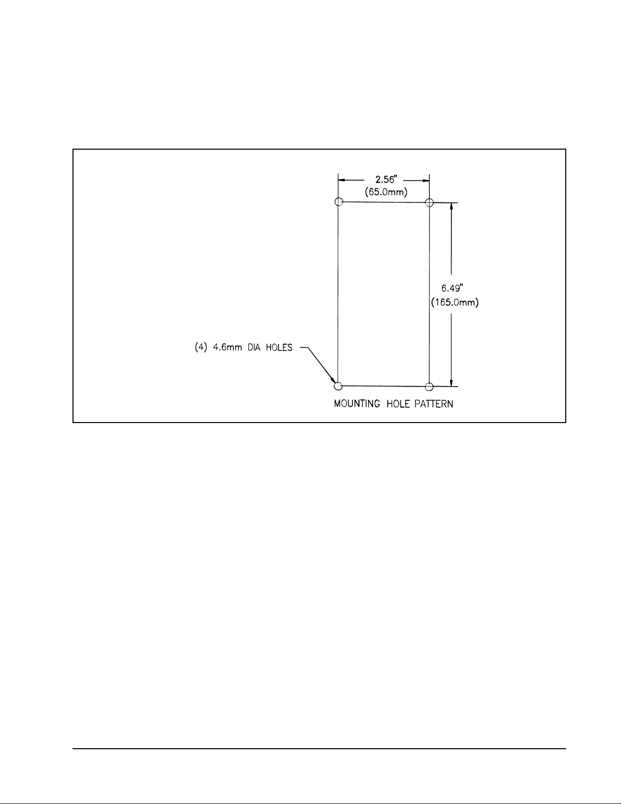
Step 2. Drill the mounting holes (4.6 mm diameter) for the circuit breaker mounting plate using the mounting
hole pattern shown in Figure 1.
Figure 1 – Inverting Fault Circuit Breaker Mounting Hole Pattern
Step 3. Mount the circuit breaker and the plate assembly with the four M5 self-tapping screws provided with
the kit.
Inverting Fault Circuit Breaker Kit for FlexPak 3000 and WebPak 3000 Drives
3
Page 4

Wiring the Inverting Fault Circuit Breaker
Step 1. Connect the motor armature lead marked A1 to the Inverting Fault Circuit Breaker terminal A1. See
Figure 2 for the location of terminal A1 on the circuit breaker.
Figure 2 – Inverting Fault Circuit Breaker Terminal Locations
Step 2. Connect the wire from the inverting fault circuit breaker terminal marked 47 (see Figure 2 for location)
to the drive motor terminal marked A1 (see Figure 3 for location).
Figure 3 – Drive Motor Terminal Block
4
Inverting Fault Circuit Breaker Kit for FlexPak 3000 and WebPak 3000 Drives
Page 5

Step 3. Connect the motor armature lead marked A2 to the drive motor terminal block (see Figure 3 for
location). If the motor has a series field, connect motor lead A2 to motor lead S1, and connect the
motor lead S2 to the drive motor terminal block marked 45.
Removing and Replacing Fuse 11FU
Step 1. Remove the drive’s front cover, then open the regulator carrier and remove the armature fuse plastic
cover over the armature fuse (11FU). Refer the drawing on the back of the carrier for the location of
11FU.
Step 2. Remove the hardware used to attach 11FU to the drive.
Step 3. Replace 11FU with the jumper/bar (part number 610273-30RN, 610273-101A, or 610273-102A)
provided with the kit. Use the hardware removed from 11FU to install the jumper/bar in place of 11FU.
Connecting the Wire Assembly
Step 1. Locate and remove the jumper wire from the 11FU terminal marked A1 and the terminal marked A1
on the Power Interface board. See Figure 4 for the location of the Power Interface board and terminal
A1 on the Power Interface board.
Figure 4 – Power Interface Board and Terminal A1 Locations
Step 2. Attach the spade connector on wire harness part number 610273-68R to the A1 terminal on the
Power Interface board. Route the other end of this wire to the inverting fault circuit breaker terminal
marked A1. Cut the wire to length as required and then terminate the end with the ring lug (part
number 68321-19D). Connect the ring lug to the A1 terminal on the inverting fault circuit breaker.
Step 3. Connect the spade connectors of the twisted pair harness (part number 610273-68S) to the male
connectors coming out of the side of the inverting fault circuit breaker. Route this harness down to the
bottom of the drive and connect it to terminals 9 and 11 on the regulator control terminal strip. See
Figure 5.
Important: If any other interlocks are required for your application, they must be connected in series to the
Customer Interlock Input (terminals 9 and 11) along with the circuit breaker.
Inverting Fault Circuit Breaker Kit for FlexPak 3000 and WebPak 3000 Drives
5
Page 6

Figure 5 – Drive Control Terminal Strip
6
Inverting Fault Circuit Breaker Kit for FlexPak 3000 and WebPak 3000 Drives
Page 7

Checking the Circuit Breaker Settings
Step 1. Visually check the setting of the circuit breaker setpoint. Set the circuit breaker settings as required.
See Table 3 for circuit breaker settings.
Table 3 – Inverting Fault Circuit Breaker Settings
Kit Model Number Drive Horsepower/Volts Required Setting
906FK0101 1.5 - 2 HP @ 230 VAC
3 - 5 HP @ 460 VAC
906FK0201 3 - 5 HP @ 230 VAC
7.5 - 10 HP @ 460 VAC
906FK0301 7.5 - 10 HP @ 230 VAC
15 - 20 HP @ 460 VAC
906FK0401 15 - 20 HP @ 230 VAC
25 - 40 HP @ 460 VAC
906FK0501 25 - 30 HP @ 230 VAC
50 - 60 HP @ 460 VAC
Step 2. Check and verify all wiring per Figure 6 before applying power to the drive. Ensure that wires are not
in contact with hot components or sharp metal edges.
Set at A (40 A)
Set at L (50 A)
Set at 2 (90 A)
Set at L (150 A)
Set at L (450 A)
Figure 6 – Inverting Fault Circuit Breaker Connection Diagram
Step 3. Set the Inverting Fault Circuit Breaker to the ON position.
Step 4. Remove the lockout and tag and reconnect power to the drive.
Step 5. Turn on power to the drive.
Kit installation is now complete.
Inverting Fault Circuit Breaker Kit for FlexPak 3000 and WebPak 3000 Drives
7
Page 8

Technical Specifications
Table 4 – Replacement Circuit Breaker Part Numbers
Kit Model Number Drive HorsePower/Voltage Rating
906FK0101 1.5 - 2 HP @ 230 VAC
3 - 5 HP @ 460 VAC
906FK0201 3 - 5 HP @ 230 VAC
7.5 - 10 HP @ 460 VAC
906FK0301 7.5 - 10 HP @ 230 VAC
15 - 20 HP @ 460 VAC
906FK0401 15 - 20 HP @ 230 VAC
25 - 40 HP @ 460 VAC
906FK0501 25 - 30 HP @ 230 VAC
50 - 60 HP @ 460 VAC
Table 5 – Inverting Fault Circuit Breaker Specifications
Kit Model
Number
906FK0101 1.5 - 2 HP @ 230 VAC
906FK0201 3 - 5 HP @ 230 VAC
906FK0301 7.5 - 10 HP @ 230 VAC
906FK0401 15 - 20 HP @ 230 VAC
906FK0501 25 - 30 HP @ 230 VAC
Drive Horsepower/
Voltage Rating
3 - 5 HP @ 460 VAC
7.5 - 10 HP @ 460 VAC
15 - 20 HP @ 460 VAC
25 - 40 HP @ 460 VAC
50 - 60 HP @ 460 VAC
Circuit Breaker
Dimensions HxWxD
6 x 4.125 x 4.12 (in)
153.4 x 105 x105 (mm)
6 x 4.25 x 4.16 (in)
153 x 115 x 106 (mm)
6 x 4.25 x 4.16 (in)
153 x 115 x 106 (mm)
6 x 4.25 x 4.16 (in)
153 x 115 x 106 (mm)
6 x 4.25 x 4.16 (in)
153 x 115 x 106 (mm)
77801-18DXA
419035-100DSA
419035-100HSA
419035-100NSA
419035-100SSA
Circuit
Breaker
Weight
4 lb
1.81 kg
4.23 lb
1.91 kg
4.23 lb
1.91 kg
4.23 lb
1.91 kg
4.23 lb
1.91 kg
Replacement Circuit Breaker
Model Number
Max
AC
Current
Rating
@ 40º C Trip Amps
Volts
50/60
Hz.
Volts
25 A 40 A 600 600
30 A 50-180 A 600 600
50 A 75-260 A 600 600
100 A 150-580 A 600 600
150 A 450-1100 A 600 600
Max
DC
Publication D2-3300-2 - February 2001
2001 Rockwell International Corporation. All rights reserved. Printed in USA.
Page 9

Page 10

U.S. Drives Technical Support
Tel: (1) 262.512.8176, Fax: (1) 262.512.2222, Email: support@drives.ra.rockwell.com, Online: www.ab.com/support/abdrives
Publication D2-3300-2 – February 2001 Copyright © 2001 Rockwell Automation, Inc. All Rights Reserved. Printed in USA.
 Loading...