

Page 1

FlexPak 3000
Field Current Regulator Kit
Installation Instructions
Instruction Manual
D2-3336-2
Page 2
The information in this manual is subject to change without notice.
Throughout this manual, the following notes are used to alert you to safety considerations:
ATTENTION:Identifies information about practices or circumstances that can lead to personal
injury or death, property damage, or economic loss.
!
Important: Identifies information that is critical for successful application and understanding of the product.
The thick black bar shown on the outside margin of this page will be used throughout this instruction manual to
signify new or revised text or figures.
ATTENTION:Only qualified electrical personnel familiar with the construction and operation of
this equipment and the hazards involved should install, adjust, operate, or service this equipment.
!
Read and understand this manual and other applicable manuals in their entirety before
proceeding. Failure to observe this precaution could result in severe bodily injury or loss of life.
ATTENTION:Do not install or remove modification kits with power applied to the drive. Disconnect
and lock out incoming power before attempting such installation or removal. Failure to observe
this precaution could result in severe bodily injury or loss of life.
ATTENTION:The user is responsible for conforming with all applicable local, national, and
international codes. Failure to observe this precaution could result in damage to, or destruction
of, the equipment.
FlexPak and Reliance are trademarks of Rockwell Automation.
Copyright © 2000 Rockwell Automation. All rights reserved.
Page 3

CONTENTS
Chapter 1 Introduction
1.1 Related Publications........................................................................................1-3
1.2 Getting Assistance from Reliance Electric.......................................................1-3
Chapter 2 Installing the Field Current Regulator Kit on 1.5 - 30 HP @ 230 VAC and
3 - 60 HP @ 460 VAC Drives
2.1 Opening the Drive Cover and Carrier..............................................................2-1
2.2 Removing the Standard or Enhanced Field Supply Board..............................2-2
2.3 Installing the Field Current Regulator Board ...................................................2-2
2.4 Wiring the Field Current Regulator Board .......................................................2-2
2.5 Replacing the Drive Fuses ..............................................................................2-3
2.6 Replacing the Carrier and Drive Cover............................................................ 2-3
2.7 Modifying the Drive Configuration ................................................................... 2-3
Chapter 3 Installing the Field Current Regulator Kit on 40 - 75 Hp @ 230 VAC and
75 - 150 HP @ 460 VAC Drives
3.1 Opening the Drive Cover and Carrier, and Removing the AC Disconnect...... 3-2
3.2 Removing the Standard or Enhanced Field Supply Board..............................3-2
3.3 Installing the Field Current Regulator Board ...................................................3-2
3.4 Wiring the Field Current Regulator Board .......................................................3-3
3.5 Replacing the Drive Fuses ..............................................................................3-3
3.6 Reinstalling the Auxiliary Chassis Cover, Carrier and Drive Cover.................3-4
3.7 Modifying the Drive Configuration ................................................................... 3-4
Chapter 4 Installing the Field Current Regulator Kit on 100 - 150 HP @ 230 VAC and
200 - 300 HP @ 460 VAC Drives
4.1 Opening the Cover and Carrier ....................................................................... 4-2
4.2 Removing the Enhanced Field Supply Board.................................................. 4-2
4.3 Installing the Field Current Regulator Board ...................................................4-2
4.4 Wiring the Field Current Regulator Board .......................................................4-3
4.5 Reinstalling the OIM Carrier and Cover........................................................... 4-3
4.6 Replacing the Drive Fuses ..............................................................................4-3
4.7 Reinstalling the Drive Cover............................................................................4-3
4.8 Modifying the Drive Configuration ................................................................... 4-4
Chapter 5 Modifying the Drive Configuration
5.1 Setting Parameter 510 (MOTOR HOT FLD AMPS) ........................................ 5-2
5.2 Setting Parameter 511 (FIELD ECONOMY REF) ........................................... 5-4
5.3 Tuning the Field Curent Regulator ...................................... ...... ....... ...... ....... .. 5-5
Appendix A Field Current Regulator Description.....................................................................A-1
Contents
I
Page 4

II
FlexPak 3000 Field Current Regulator Installation Instructions
Page 5

List of Figures
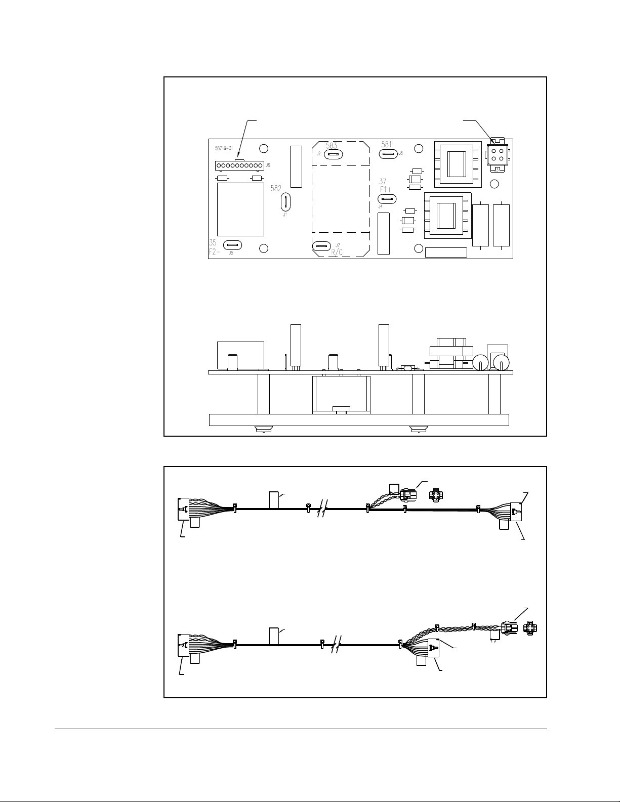
Figure 1.1 – Field Current Regulator Board..............................................................1-2
Figure 1.2 – Cable Assemblies.................................................................................1-2
Figure 2.1 – Removing the Standard/Enhanced Field Supply..................................2-4
Figure 2.2 – Cable Routing (3 - 60 HP Drives)......................................................... 2-5
Figure 2.3 – Regulator Board Cable Connectors......................................................2-5
Figure 2.4 – Attaching Replacement Drive Fuse Labels (3 - 60 HP Drives)............. 2-6
Figure 3.1 – Removing the Standard/Enhanced Field Supply (75 - 150 HP Drives) 3-5
Figure 3.2 – Cable Routing (75 - 150 HPDrives)...................................................... 3-5
Figure 3.3 – Attaching Replacement Drive Fuse Labels (75 - 150 HP Drives).........3-6
Figure 4.1 – Removing the Standard/Enhanced Field Supply (200 - 300 HP Drives) 4-4
Figure 4.2 – Cable Routing (200 - 300 HP Drives)................................................... 4-4
Contents
III
Page 6

IV
FlexPak 3000 Field Current Regulator Installation Instructions
Page 7

List of Tables
Table 1.1 – Verifying the Field Current Regulator Kit Matches the Drive ................. 1-1
Table 1.2 – Field Current Regulator Kit Contents.....................................................1-1
Contents
V
Page 8

VI
FlexPak 3000 Field Current Regulator Installation Instructions
Page 9
CHAPTER 1
Introduction
This instruction manual describes how to install and configure the optional Field
Current Regulator kits used by FlexPak
which includes a field regulator and a field supply, can be used only in drives that have
software version 3.00 (
REGULAT O R SW VERSION parame ter = 3.00 ) or late r . W hen t he ki t
is installed, a field control loop is enabled, allowing the user to adjust field control
functions. The field control loop operates in both the constant torque (armature
control) range and the constant power (field control) range. See Appendix A for a
description of the field control loop.
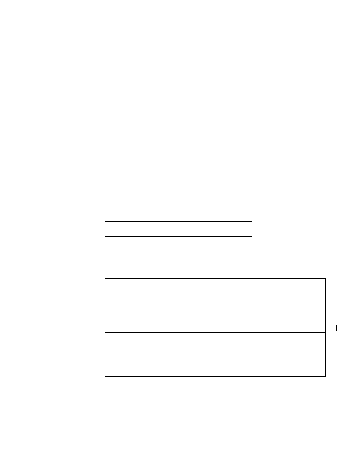
There are three Field Current Regulator kits available for use in FlexPak 3000 drives.
They differ according to the maximum motor field current they support. Use the kit that
provides the maximum motor field current required for your application. Note that
using a Field Current Regulator with a higher amperage rating than is needed will
decrease control resolution. Refer to table 1.1 to ensure you have the correct kit for
your application and to table 1.2 for a list of the kit contents. See figures 1.1 and 1.2 for
illustrations of the Field Current Regulator board and cable assemblies.
Table 1.1 – Verifying the Field Current Regulator Kit Matches the Drive
™ 3000 drives. The Field Current Regulator,
Field Current Regulator
Model Number
Maximum Motor
Field Current
911FK0041 4 A
911FK0101 10 A
911FK0151 15 A
Table 1.2 – Field Current Regulator Kit Contents
Part Number Description Quantity
707973-10R
707973-10S
707973-10T
1
2
3
Printed Circuit Board Assembly 1
64676-30M 25 A Fuse, UL Class CC, 600 V 3
179540 Fuse Rating Label 4
707973-12R
707973-12S
4
5
Cable Assembly 1
Cable Assembly 1
69306-3D Cable Tie Wrap 8
69752-146D Plug Cap 1
D2-3336-2 Instruction Manual 1
1
Kit M/N 911FK0041
2
Kit M/N 911FK0101
3
Kit M/N 911FK0151
4
Used for 3-60 HP @ 460 VAC drives
5
Used for 75-150 HP @ 460 VAC and 200-300 HP @ 460 VAC drives
Introduction
1-1
Page 10
Top View
FLD P6
Connector
FLD P3
Connector
Side View
5
G
2
E
P
R
12-pin PCB C onnector
(REG P25)
G
5
E
2
P
R
12-pin PCB C onnector
(REG P25)
Figure 1.1 – Field Current Regulator Board
Part Number Label
FlexPak 3000 P/N 707973-12R
Part Number Label
FlexPak 3000 P/N 707973-12S
Figure 1.2 – Cable Assemblies
4-pin Square Connector
(FL D P3 )
10-pin PCB Connector
(FL D P 6)
4-pin Square Connector
(FL D P3 )
PIN-1
D
6
L
P
F
10-pin PCB Connector
(FL D P6 )
PIN-1
D
L
6
F
P
1-2
FlexPak 3000 Field Current Regulator Installation Instructions
Page 11

1.1 Related Publications
Refer to the following related publications as necessary for more information:
• D2-3404
• D2-3405
FlexPak 3000 DC Drive Hardware Reference Manual
FlexPak 3000 Digital DC Drive Software Reference Manual
1.2 Getting Assistance from Reliance Electric
If you have any questions or problems with the products described in this instruction
manual, contact your local Reliance Electric sales office. For technical assistance, call
1-800-726-8112.
Introduction
1-3
Page 12

1-4
FlexPak 3000 Field Current Regulator Installation Instructions
Page 13
CHAPTER 2
Installing the Field Current Regulator Kit
on 1.5 - 30 HP @ 230 VAC and
3 - 60 HP @ 460 VAC Drives
ATTENTION:Only qualified personnel familiar with the construction and
operation of this equipment and the hazards involved should install,
!
Installing the Field Current Regulator kit on 3 - 60 HP drives requires completing the
following steps. When you have finished installing the kit, adjust the required drive
parameters as described in chapter 5 before using the drive.
adjust, operate, and/or service this equipment. Read and understand
this instruction manual in its entirety before proceeding. Failure to
observe this precaution could result in severe bodily injury or loss of life.
ATTENT IO N:The drive is at line voltage when connected to incoming
ac power. Disconnect, tag, and lockout all incoming power to the drive
before performing the following procedure. Failure to observe this
precaution could result in severe bodily injury or loss of life.
• Opening the cover and carrier
• Removing the Standard or Enhanced Field Supply board
• Installing the Field Current Regulator board
• Wiring the Field Current Regulator board
• Replacing the drive fuses
• Reinstalling the drive carrier and cover
• Modifying the drive configuration
These steps are descri bed in the following sections.
Installing the Field Current Regulator Kit on 1.5 - 30 HP @ 230 VAC and 3 - 60 HP @ 460 VAC Drives
2-1
Page 14

2.1 Opening the Drive Cover and Carrier
ATTENTION:The drive contains ESD- (Electrostatic Discharge)
sensitive parts and assemblies. Static control precautions are required
!
Step 1. Turn off, lockout, and tag power to the drive.
Step 2. Loosen the cover retaining screws and remove the cover.
Step 3. Loosen the captive screw at the upper right corner of the drive’s Operator
when installing, testing, servicing, or repairing the drive. Erratic machine
operation and damage to, or destruction of, equipment can result if this
procedure is not followed. Failure to observe this precaution can result
in bodily injury.
Interface Module (OIM) carrier and swing open the carrier.
2.2 Removing the Standard or Enhanced Field Supply
Board
Step 1. Locate the Standard or Enhanced Field Supply board in the drive. See figure
2.1.
Step 2. Disconnect the drive’s wire harness connections from the existing field
supply board’s 581, 582, 583, F2/35 and F1/37 spade connectors. Follow the
field supply board’s wire harness to the P4 connector on the Power Interface
board. Unplug the harness from the P4 connector.
Step 3. Follow the field supply board’s wire harness to the P4 connector on the
Power Interface board. Unplug the harness from the P4 connector.
Step 4. Install the plug cap (P/N 69752-146D) on the Power Interface board’s P4
connector. See figure 2.1.
Step 5. Locate the field supply’s four mounting screws on the outside of the drive’s
right side panel.
Step 6. Remove the four mounting screws from the outside of the dive and remove
the field supply board.
2.3 Installing the Field Current Regulator Board
Step 1. Remove the four mounting screws from the back of the Field Current
Regulator assembly.
Step 2. Connect the wire harness connectors labeled 581, 582, 583, F2/35 and
F1/37 to the corresponding terminals on the Field Current Regulator board.
See figure 1.1.
Step 3. Attach the Field Current Regulator cable assembly’s (P/N 707973-12R) FLD
P6 and FLD P3 connectors to the corresponding terminals on the Field
Current Regulator board. See figure 1.1.
Step 4. Working from the inside of the drive, align the Field Current Regulator
board’s mounting holes with the mounting holes on the drive’s right side
panel. See figure 2.2.
Step 5. Working from the outside of the drive, insert one of the mounting screws
(removed in step 1) through one of the mounting holes on the drive’s right
side panel and into the corresponding mounting hole on the Field Current
Regulator board.
Step 6. Repeat step 5 for the remaining three mounting holes.
2-2
FlexPak 3000 Field Current Regulator Installation Instructions
Page 15

2.4 Wiring the Field Current Regulator Board
Step 1. The Operator Interface Module (OIM) or Drive Configuration Module (DCM)
must be removed to provide access to the Regulator board. Remove the
screws that hold the OIM or DCM to the carrier, and remove the OIM/DCM.
Step 2. Remove the three screws that hold the Regulator board in place, and slide
the Regulator board slightly to the right.
Step 3. From the back of the carrier, push the end of the Field Current Regulator
cable assembly with the REG P25 connector through the opening in the
carrier (above the ribbon cable). See figure 2.2.
Step 4. Connect the REG P25 connector to the J25 terminal on the Regulator board.
See figure 2.3.
Step 5. Slide the Regulator board back into place and secure it with its mounting
screws.
Step 6. Reinstall the OIM/DCM.
Step 7. Use the supplied cable ties to fasten the Field Current Regulator cable
assembly to the drive’s fan or support bar.
2.5 Replacing the Drive Fuses
Step 1. Remove the three fuses labeled 6FU, 7FU, and 8FU from the drive’s fuse
block.
Step 2. Install the three provided 25 A, 600 V fuses (P/N 64676-30M) in the fuse
block in positions 6FU, 7FU, and 8FU.
Step 3. Locate the replacement fuse table on the back of the carrier. Attach one of
the adhesive fuse rating labels (P/N 179540) over each of the places
indicated in figure 2.4.
2.6 Replacing the Carrier and Drive Cover
Step 1. Close the carrier and secure it in place with its captive screw.
Step 2. Reinstall the drive cover and secure it in place with its screws.
Step 3. Reconnect power to the drive. Hardware installation is complete.
Step 4. Remove the lockout and tag.
Step 5. Turn on power to the drive.
2.7 Modifying the Drive Configuration
Go to chapter 5 for information on setting parameters for the Field Current Regulator
kit.
Installing the Field Current Regulator Kit on 1.5 - 30 HP @ 230 VAC and 3 - 60 HP @ 460 VAC Drives
2-3
Page 16

Power I/F Board
P4 Connector
FlexPak Wire
Harness
Standard or Enhanced
Carrier
Figure 2.1 – Removing the Standard/Enhanced Field Supply
Field Supply
2-4
FlexPak 3000 Field Current Regulator Installation Instructions
Page 17

Front View
Side View
Carrier
Fan
J25 Connector
Field Supply
Attaching
Screws
(Q ty 4)
FlexPak Wire
Harness
Field Current
Regulator
Field Current Regulator
Cable Assembly
Figure 2.2 – Cable Routing (3 - 60 HP Drives))
J6 Connector
Field Current Regulator
Cable Assembly
J7 Connector
Figure 2.3 – Regulator Board Cable Connectors
Installing the Field Current Regulator Kit on 1.5 - 30 HP @ 230 VAC and 3 - 60 HP @ 460 VAC Drives
J5 Connector
2-5
Page 18

Figure 2.4 – Attaching Replacement Drive Fuse Labels (3 - 60 HP Drives)
600V 25A
2-6
FlexPak 3000 Field Current Regulator Installation Instructions
Page 19

CHAPTER 3
Installing the Field Current Regulator Kit
on 40 - 75 HP @ 230 VAC and
75 - 150 HP @ 460 VAC Drives
ATTENTION:Only qualified personnel familiar with the construction and
operation of this equipment and the hazards involved should install,
!
Installing the Field Current Regulator kit on 75-150 HP drives requires completing the
following steps. When you have finished installing the kit, adjust the required drive
parameters as described in chapter 5 before using the drive.
adjust, operate, and/or service this equipment. Read and understand
this instruction manual in its entirety before proceeding. Failure to
observe this precaution could result in severe bodily injury or loss of life.
ATTENT IO N:The drive is at line voltage when connected to incoming
ac power. Disconnect, tag, and lockout all incoming power to the drive
before performing the following procedure. Failure to observe this
precaution could result in severe bodily injury or loss of life.
• Opening the cover and carrier
• Removing the Standard or Enhanced Field Supply board
• Installing the Field Current Regulator board
• Wiring the Field Current Regulator board
• Replacing the drive fuses
• Reinstalling the drive carrier and cover
• Modifying the drive configuration
These steps are descri bed in the following sections.
Installing the Field Current Regulator Kit on 40 - 75 HP @ 230 VAC and 75 - 150 HP @ 460 VAC Drives
3-1
Page 20

3.1 Opening the Drive Cover and Carrier, and Removing
the AC Disconnect
ATTENTION:The drive contains ESD- (Electrostatic Discharge)
sensitive parts and assemblies. Static control precautions are required
!
Step 1. Turn off, lockout, and tag power to the drive.
Step 2. Loosen the drive cover retaining screws and remove the cover.
Step 3. Loosen the captive screw at the upper right corner of the drive’s Operator
Step 4. Drives with an AC line disconnect only: Remove the four screws that
Step 5. Loosen the two screws at the right side of the motor terminal panel to free the
Step 6. Remove the top and bottom screws fastening the auxiliary chassis cover to
Step 7. Loosen the middle screw that fastens the auxiliary chassis cover/circuit
when installing, testing, servicing, or repairing the drive. Erratic machine
operation and damage to, or destruction of, equipment can result if this
procedure is not followed. Failure to observe this precaution can result
in bodily injury.
Interface Module (OIM) carrier and swing open the carrier. If the drive is
equipped with an AC line disconnect, go to step 4. Otherwise, go to step 5.
fasten the AC line disconnect to the auxiliary chassis cover. Then, lift and
remove the AC line disconnect from the auxiliary chassis cover. See figure
3.1.
tabs on the auxiliary chassis cover. Do not to remove the screws completely.
See figure 3.1.
the drive’s right side panel.
breaker panel to the drive’s right side panel. Slightly swing out the auxiliary
chassis cover and remove it.
3-2
3.2 Removing the Standard or Enhanced Field Supply
Board
Step 1. Locate the Standard or Enhanced Field Supply board in the drive. See figure
3.1.
Step 2. Disconnect the drive’s wire harness connections from the existing field
supply board’s 581, 582, 583, F2/35 and F1/37 spade connectors.
Step 3. Follow the field supply board’s twisted-pair harness to the P4/S4 connectors.
Unplug the harness from the P4/S4 connector.
Step 4. Install the plug cap (P/N 69752-146D) on the drive control harness S4
connector.
Step 5. Remove the four (4) mounting screws from the outside of the drive’s right
side panel and remove the field supply board.
3.3 Installing the Field Current Regulator Board
Step 1. Remove the four (4) mounting screws from the back of the Field Current
Regulator board.
FlexPak 3000 Field Current Regulator Installation Instructions
Page 21

Step 2. Connect the drive’s wire harness connectors labeled 581, 582, 583, F2/35
and F1/37 to the corresponding terminals on the Field Current Regulator
board. See figure 1.1 for the location of the terminals.
Step 3. Attach the Field Current Regulator cable assembly (P/N 707973-12S) FLD
P6 and FLD P3 connectors to the corresponding terminals on the Field
Current Regulator. See figure 1.1.
Step 4. Route the free end of the Field Current Regulator cable assembly under the
fuse block, through the grommet, and across the heat sink, to the left side of
the drive following the same path as the red and blue control wiring harness.
Then run the cable assembly inside the front of the drive to the OIM carrier.
See figure 3.2.
Step 5. Working from the inside of the drive, align the Field Current Regulator
board’s mounting holes with the mounting holes on the drive’s right side
panel.
Step 6. Working from the outside of the drive, insert one of the mounting screws
(removed in step 1) through one of the mounting holes on the drive’s right
side panel and into the corresponding mounting hole on the Field Current
Regulator board. Tighten the screw to hold the board in place.
Step 7. Repeat step 6 for the remaining three mounting screws.
3.4 Wiring the Field Current Regulator Board
Step 1. The Operator Interface Module (OIM) or Drive Configuration Module (DCM)
must be removed to provide access to the Regulator board. Remove the
screws that hold the OIM (or DCM) to the carrier, and remove the OIM/DCM.
Step 2. Remove the three screws that hold the Regulator board in place, and slide
the Regulator board slightly to the right.
Step 3. From the back of the carrier, push the end of the Field Current Regulator
cable assembly with the REG P25 connector through the opening in the
carrier (above the ribbon cable). See figure 3.2.
Step 4. Connect the REG P25 connector to the J25 terminal on the Regulator board.
See figure 2.3.
Step 5. Slide the Regulator board back into place and secure it with its mounting
screws.
Step 6. Reinstall the OIM/DCM.
Step 7. Use the supplied cable ties to fasten the Field Current Regulator cable
assembly to the drive control harness. See figure 3.2
3.5 Replacing the Drive Fuses
Step 1. Remove the three fuses labeled 6FU, 7FU, and 8FU from the drive’s fuse
block.
Step 2. Install the three provided 25 A, 600 V fuses (P/N 64676-30M) in the fuse
block in positions 6FU, 7FU, and 8FU.
Step 3. Locate the replacement fuse table on the back of the carrier. Attach one of
the adhesive fuse rating labels (P/N 179540) over each of the places
indicated in figure 3.3.
Installing the Field Current Regulator Kit on 40 - 75 HP @ 230 VAC and 75 - 150 HP @ 460 VAC Drives
3-3
Page 22

3.6 Reinstalling the Auxiliary Chassis Cover , Carrier and
Drive Cover
Step 1. Insert the tabs on the left side of the auxiliary chassis cover into the slots on
the right side of the drive’s motor terminal panel.
Step 2. Align the auxiliary chassis cover over the middle screw on the drive’s right
side panel and over the top and bottom mounting holes.
Step 3. Insert the top and bottom screws into the mounting screw holes and then
tighten all three mounting screws (top, bottom, and middle).
Step 4. Tighten the two screws on the right side of the motor terminal panel to secure
the auxiliary chassis cover’s tabs in place.
Step 5. Drives with an AC line disconnect only: Align the AC line disconnect over
the mounting holes on the auxiliary chassis cover, then secure it in place with
the four screws removed earlier.
Step 6. Close the OIM carrier and secure it i n place with its captive screw.
Step 7. Reinstall the drive cover and secure it in place with its screws. Hardware
installation is complete.
Step 8. Reconnect power to the drive.
Step 9. Remove the lockout and tag.
Step 10. Turn on power to the drive.
3.7 Modifying the Drive Configuration
Go to chapter 5 for information on setting parameters for the Field Current Regulator
kit.
3-4
FlexPak 3000 Field Current Regulator Installation Instructions
Page 23

Motor Terminal Panel
Loosen screws
Loosen screws
Remove 4 screws
Auxiliary
Chassis
Cover
Drive without AC D isconnect
Rem ove top and
bo tto m scre w s ;
loosen middle screw
Drive with Aux. Chassis
Cover Removed
R e mo v e to p a n d
bo tto m scre w s ;
loosen middle screw
Drive with AC Disconnect
Field Supply
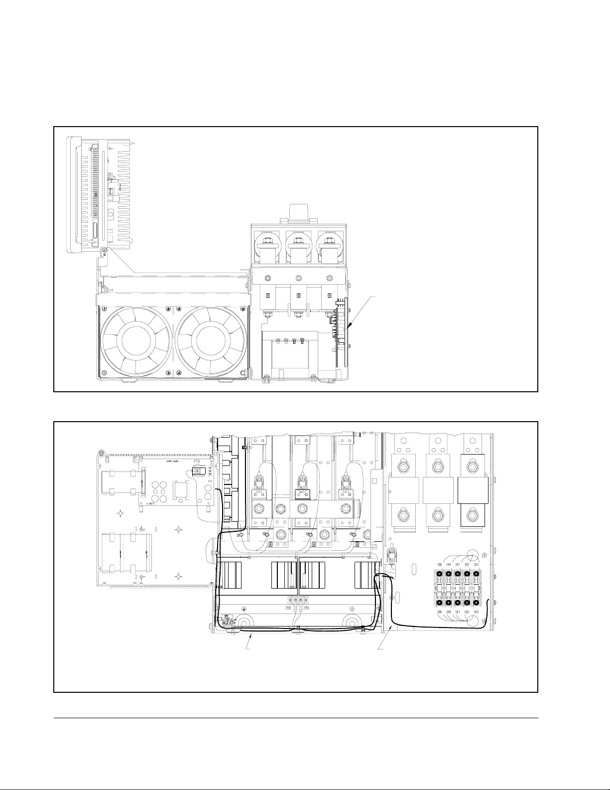
Figure 3.1 – Removing the Standard/Enhanced Field Supply (75 - 150 HP Drives)
Top View Front Vie w
Field Current
Regulator Cable
Assembly
Field Current
Regulator Cable
Assembly
Figure 3.2 – Cable Routing (75 - 150 HP Drives)
Field Current
Regulator
Installing the Field Current Regulator Kit on 40 - 75 HP @ 230 VAC and 75 - 150 HP @ 460 VAC Drives
3-5
Page 24

Figure 3.3 – Attaching Replacement Drive Fuse Labels (75 - 150 HP Drives)
600V 25A
600V 25A
3-6
FlexPak 3000 Field Current Regulator Installation Instructions
Page 25

CHAPTER 4
Installing the Field Current Regulator Kit
on 100 - 150 HP @ 230 VAC and
200 - 300 HP @ 460 VAC Drives
ATTENTION:Only qualified personnel familiar with the construction and
operation of this equipment and the hazards involved should install,
!
Installing the Field Current Regulator kit on 200-300 HP drives requires completing
the following steps. When you have finished installing the kit, adjust the required drive
parameters as described in chapter 5 before using the drive.
adjust, operate, and/or service this equipment. Read and understand
this instruction manual in its entirety before proceeding. Failure to
observe this precaution could result in severe bodily injury or loss of life.
ATTENT IO N:The drive is at line voltage when connected to incoming
ac power. Disconnect, tag, and lockout all incoming power to the drive
before performing the following procedure. Failure to observe this
precaution could result in severe bodily injury or loss of life.
• Opening the cover and carrier
• Removing the Enhanced Field Supply board
• Installing the Field Current Regulator board
• Wiring the Field Current Regulator board
• Replacing the drive fuses
• Reinstalling the drive carrier and cover
• Modifying the drive configuration
These steps are descri bed in deta il below.
Installing the Field Current Regulator Kit on 100 - 150 HP @ 230 VAC and 200 - 300 HP @ 460 VAC Drives
4-1
Page 26

4.1 Opening the Cover and Carrier
ATTENTION:The drive contains ESD- (Electrostatic Discharge)
sensitive parts and assemblies. Static control precautions are required
!
Step 1. Turn off, lockout, and tag power to the drive.
Step 2. Remove the plastic cover from the right side of the drive.
Step 3. Loosen the two screws holding the OIM cover in place and remove the OIM
Step 4. Loosen the captive screw at the upper right corner of the OIM carrier and
Step 5. Locate the two plastic anchors holding the hinged mounting panel in place.
when installing, testing, servicing, or repairing the drive. Erratic machine
operation and damage to, or destruction of, equipment can result if this
procedure is not followed. Failure to observe this precaution can result
in bodily injury.
cover.
then swing the carrier open. Note that the screw is designed to stay attached
to the carrier when it is loosened; do not attempt to remove it.
Release the anchors by inserting the tip of a flat-bladed screwdriver into the
notch on the anchors and twist so the notch is vertical. Then swing the panel
open.
4.2 Removing the Enhanced Field Supply Board
Step 1. Locate the Enhanced Field Supply board. It is attached to the right side of the
drive, behind the line fuse panel, and can be accessed through the bottom of
the drive. See figure 4.1.
Step 2. Remove the four field supply mounting screws from the outside of the drive’s
right side panel and remove the field supply.
Step 3. Disconnect the drive’s wire harness from the field supply board’s 581, 582,
583, F2/35, and F1/37 connectors.
Step 4. Follow the field supply board’s twisted-pair harness to the P4/S4 connectors.
Unplug the harness from the P4/S4 connector.
Step 5. Install the plug cap (P/N 69752-146D) on the drive control harness S4
connector.
4.3 Installing the Field Current Regulator Board
Step 1. Remove the four (4) mounting screws from the back of the Field Current
Regulator board.
Step 2. Connect the drive’s wire harness connectors labeled 582, 582, 583, F2/35,
and F1/37 to the corresponding terminals on the Field Current Regulator
board. See figure 1.1 for the location of the terminals.
Step 3. Attach the Field Current Regulator cable assembly (P/N 707973-12S)
connectors FLD P6 and FLD P3 to the corresponding terminals on the Field
Current Regulator.
Step 4. Route the free end of the Field Current Regulator cable assembly to the left
side of the drive and into the OIM carrier. Follo w the path illustrated in figure
4.2. This is the same path used by the control wiring harness.
4-2
FlexPak 3000 Field Current Regulator Installation Instructions
Page 27

Step 5. Working from the inside of the bottom of the drive, align the Field Current
Regulator board’s mounting holes with the mounting holes on the drive’s right
side panel. See figure 4.2.
Step 6. Working from the outside of the drive, insert one of the mounting screws
(removed in step 1) through one of the mounting holes on the drive’s right
side panel and into the corresponding mounting hole on the Field Current
Regulator board. Tighten the screw to hold the board in place.
Step 7. Repeat step 6 for the remaining three mounting screws.
4.4 Wiring the Field Current Regulator Board
Step 1. The Operator Interface Module (OIM) or Drive Configuration Module (DCM)
must be removed to provide access to the Regulator board. Remove the
screws that hold the OIM (or DCM) to the carrier, and remove the OIM/DCM.
Step 2. Remove the three screws that hold the Regulator board in place, then slide
the Regulator board slightly to the right.
Step 3. From the back of the OIM carrier, push the end of the Field Current Regulator
cable assembly with the REG P25 connector through the opening in the
carrier (above the ribbon cable).
Step 4. Connect the REG P25 connector to the J25 terminal on the Regulator board.
See figure 2.3.
Step 5. Slide the Regulator board back into place and secure it with its mounting
screws.
Step 6. Reinstall the OIM/DCM.
4.5 Reinstalling the OIM Carrier and Cover
Step 1. Swing the mounting panel back into the closed position, and secure it by
twisting the notches on the two plastic anchors into a horizontal position.
Step 2. Close the OIM carrier and secure it i n place with its captive screw.
Step 3. Reinstall the OIM/DCM cover.
4.6 Replacing the Drive Fuses
Step 1. Locate the fuse block on the drive’s line fuse panel. See figure 4.2.
Step 2. Remove the three fuses labeled 6FU, 7FU, and 8FU from the fuse block.
Step 3. Install the three provided 25 A, 600 V fuses (P/N 65676-30M) in the fuse
block in positions 6FU, 7FU, and 8FU.
4.7 Reinstalling the Drive Cover
Step 1. Reinstall the cover over the right side of the drive.
Step 2. Reinstall the plastic cover over the drive’s line fuse panel. Hardware
installation is complete.
Step 3. Reconnect power to the drive.
Step 4. Remove the lockout and tag.
Step 5. Turn on power to the drive.
Installing the Field Current Regulator Kit on 100 - 150 HP @ 230 VAC and 200 - 300 HP @ 460 VAC Drives
4-3
Page 28
4.8 Modifying the Drive Configuration
Go to chapter 5 for information on setting parameters for the Field Current Regulator
kit.
Enhanced
Field Supply
Board
Figure 4.1 – Removing the Standard/Enhanced Field Supply (200 - 300 HP Drives)
Control Harness
Field Current Regulator
Cable
4-4
Figure 4.2 – Cable Routing (200 - 300 HP Drives)
FlexPak 3000 Field Current Regulator Installation Instructions
Page 29

Installing the Field Current Regulator Kit on 100 - 150 HP @ 230 VAC and 200 - 300 HP @ 460 VAC Drives
4-5
Page 30

4-6
FlexPak 3000 Field Current Regulator Installation Instructions
Page 31

CHAPTER 5
Modifying the Drive Configuration
Before you can use the Field Current Regulator kit, you must set the parameters listed
below in the FlexPak 3000 drive. These parameters are described in sections 5.1 and
5.2.
• Parameter 510 (MOTOR HOT FLD AMPS)
• Parameter 511 (FIELD ECONOMY REF)
In addition, the input parameters listed below may need to be adjusted in order to tune
the field control loop. Refer to your drive’s instruction manual for a complete
description of these parameters.
• Parameter 501 (FIELD ECONOMY DELAY)
• Parameter 512 (FIELD LOSS THRESHOLD)
• Parameter 513 (FIELD REF REGISTER)
• Parameter 514 (FIELD PI PROP GAIN)
• Parameter 515 (FIELD PI LEAD FREQ)
• Parameter 516 (FLD FEEDBACK GAIN ADJ)
• Parameter 517 (FIELD AUTO WEAKEN)
• Parameter 518 (FLD WEAKEN THRESHOLD)
• Parameter 519 (FLD WEAKEN PROP GAIN)
• Parameter 520 (FLD WEAKEN LEAD FREQ)
• Parameter 587 (FIELD DELTA HIGH LIM)
• Once the Field Current Regulator kit is installed and the drive is configured, the
following output parameters can be used. Refer to your drive instruction manual for
complete descriptions of these output parameters.
• Parameter 586 (FLD CURRENT REGULATOR)
• Parameter 588 (FIELD DELTA)
• Parameter 589 (FIELD FEEDBACK)
• Parameter 590 (FIELD REFERENCE)
If you are installing and setting up the Field Current Regulator kit as part of your initial
drive setup, and are using the quick start procedure described in the drive’s instruction
manual, you will be prompted for parameter 510 (
after you finish with the quick start procedure, make sure that you set parameter 511
FIELD ECONOMY REF).
(
MOTOR HOT FLD AMPS). In this case,
Modifying the Drive Configuration
5-1
Page 32

If you are installing and setting up the Field Current Regulator kit after you have
already set up the drive, you do not need to rerun the quick start procedure. Simply
access the parameters and set the values as described in sections 5.1 and 5.2.
5.1 Setting Parameter 510 (MOTOR HOT FLD AMPS)
When the driv e is fir st pow ered up after inst allin g the Fiel d Current Regula tor , the F ield
Current Regulator will operate in a fixed voltage mode until a valid value is entered for
MOTOR HOT FLD AMPS. This fixed voltage will produce 150 VDC on a 230 VAC line or
300 VDC on a 460 VAC line. If your motor field voltage is significantly less than this,
begin with step 1. Otherwise, begin with step 7 if your drive is equipped with an OIM,
or step 18 if your drive is equipped with a DCM.
If the motor field voltage is less than 150 VDC on a 230 V AC line or less than 300 VDC
on a 460 VAC line, complete steps 1-6 first. Otherwise, go to step 9.
Step 1. Disconnect, tag, and lockout power to the drive.
Step 2. Disconnect the motor field winding from the drive.
Step 3. Reconnect power to the drive.
Step 4. Remove the lockout and tag.
Step 5. Turn on power to the drive.
Step 6. After completing power-up diagnostics, the drive will generate a field current
loss fault. Ignore this fault.
Step 7. Access the Fault menu by pressing the FAULT key until FAULT appears on
the OIM directly above the FAULT key.
Step 8. Select Clear Fault Log and Reset Faults, and then press ENTER. The fault
log will be cleared and all drive faults will be reset.
If the drive is equipped with an OIM, complete the following steps to set MO TOR
HOT FLD AMPS. Otherwise, go to step 18.
Step 9. Select
MOTOR HOT FLD AMPS by taking the following path from the main menu:
Field
|____Field Current Regulator
|____Field Loop Feedback Scaling
Step 10.Set
MOTOR HOT FLD AMPS to the value printed on the motor nameplate.
Step 11. Select MEMORY SAVE by taking the following path from the main menu:
Operator Interface
|____Memory Operations
Step 12. Perform the Memory Save operation.
If the motor field winding was disconnected in step 2 above, perform steps
13-17. Otherwise, go to step 18.
Step 13. Disconnect, tag, and lockout power to the drive.
Step 14. Reconnect the motor field winding to the drive.
Step 15. Reconnect power to the drive.
5-2
Step 16. Remove the lockout and tag.
FlexPak 3000 Field Current Regulator Installation Instructions
Page 33

Step 17. Turn on power to the drive.
Step 18. Access the Fault menu by pressing the FAULT key until FA ULT appears on
the OIM directly above the FAULT key.
Step 19. Select Clear Fault Log and Reset Faults, and then press ENTER. The fault
log will be cleared and all drive faults will be reset. If you have an OIM, you
are done with setting parameter 510. Go to section 5.1 to set parameter 511
FIELD ECONOMY REF).
(
Important: Performing a Restore Defaults operation will cause the Field Current
Regulator to re-enter the fixed voltage mode of operation and require the
re-execution of the above s teps.
If the drive is equipped with a DCM, use the following steps to set MOTOR HOT
FLD AMPS.
Step 20. From the main menu, scroll to Input Parameters and press ENTER.
Step 21. Scroll to
HOT FLD AMPS.
Step 22.Set
HOT FLD AMPS to the value printed on the motor nameplate.
Step 23. From the main menu, scroll to Memory Operations and press ENTER.
Step 24. Scroll to Memory Save, and then perform the memory save operation.
If the motor field winding was disconnected in step 2 above, perform steps
25-29. Otherwise, proceed to step 30.
Step 25. Disconnect, tag, and lockout power to the drive.
Step 26. Reconnect the motor field winding to the drive.
Step 27. Reconnect power to the drive
Step 28. Remove the lockout and tag.
Step 29. Turn on power the drive.
Step 30. Access the Fault menu and press ENTER.
Step 31. Scroll to Clear Fault Log and Reset Faults, and then press ENTER. The fault
log will be cleared and all drive faults will be reset.
Important: Performing a Restore Defaults operation will cause the Field Current
Regulator to re-enter the fixed voltage mode of operation and require the
re-execution of the above s teps.
Modifying the Drive Configuration
5-3
Page 34

5.2 Setting Parameter 511 (FIELD ECONOMY REF)
ATTENTION:Improper setting of the field economy ref parameter can
cause a motor overvoltage condition. Set the
!
parameter to the motor’s nameplate value. Make sure the
REF parameter and/or FIELD REF parame ter (P.513) are above the FIELD
LOSS THRESHOLD parameter (P.512). Failure to observe this precaution
could result in bodily injury and damage to the equipment.
For proper drive operation, the value for parameter 511 (FIELD ECONOMY REF) must be
set above the value for parameter 512 (
value for
THRESHOLD is 60% of MOTOR HOT FLD AMPS. Using the defaults for parameters 511 and
FIELD ECONOMY REF is 0% and that the default value for FIELD LOSS
FIELD LOSS THRESHOLD). Note that the default
512 will result in a drive fault.
MOTOR HOT FLD AMPS
FIELD ECONOMY
See your drive’s manual for more information on setting the
FIELD LOSS THRESHOLD
parameter properly. Then complete the following steps.
If the drive is equipped with an OIM, complete steps 1-6. If the drive is equipped
with a DCM, skip to step 7.
Step 1. Select
FIELD LOSS THRESHOLD by taking the following path form the main
menu:
Field
|____Field Current Regulator
|____Field Loop Configure
Step 2. Note the value of
Step 3. Back up to the Field Loop Configure menu and select
Step 4. Set the value of
THRESHOLD.
FIELD LOSS THRESHOLD.
FIELD ECONOMY REF.
FIELD ECONOMY REF to a value higher than that of FIELD LOSS
Step 5. Select MEMORY SAVE by taking the following path from the main menu:
Operator Interface
|____ Memory Operations
Step 6. Perform the Memory Save operation.
If the drive is equipped with a DCM, complete the following steps:
Step 7. From the main menu, scroll to Input Parameters and press ENTER.
Step 8. Scroll to
FIELD LOSS THRESHOLD and note its value.
5-4
Step 9. Scroll to
Step 10.Set the value of
THRESHOLD.
FIELD ECONOMY REF.
FIELD ECONOMY REF to a value higher than that of FIELD LOS S
Step 11. From the main menu, scroll to Memory Operations and press ENTER.
Step 12. Scroll to Memory Save, and then perform the memory save operation.
The installation procedure for the Field Current Regulator kit is now complete.
FlexPak 3000 Field Current Regulator Installation Instructions
Page 35

5.3 Tuning the Field Current Regulator
Important: Please review Appendix A for a complete description of the functions of
the field current regulator prior to proceeding with manual tuning.
In order to provide proper and responsive field current control the user may be
required to modify the tuning parameters to meet the needs of the application.
Adjustment of the field regulator tuning may be required to properly clamp and
regulate the armature voltage at or above base speed motor operation.
Typically the regulator parameter settings should be adjusted so that the armature
terminal transient voltage does not exceed 115% of the rated terminal volts when the
motor is operated at or above base speed. Operation above base speed requires the
use of an extended speed range rated motor.
Typical maximum armature transient voltage levels:
• 575 VDC for 500 VDC rated motor
• 275 VDC for 240 VDC rated motor.
Over voltage of the armature could result from:
• Speed overshoot above base speed of the motor during acceleration
• Acceleration into the extended speed range operation of the motor.
Note that steady state operating armature voltage levels should be rated voltage.
5.3.1 Verifying Proper Field Regulator Tuning
During initial setup of the drive and motor, the commissioning engineer should verify
that the armature voltage is properly clamped during acceleration to motor base
speed and beyond. The motor armature voltage should be monitored during
acceleration. If the motor voltage exceeds the recommended levels during operation,
the field regulator tuning may need to be adjusted.
Tuning Techniques:
The field current regulator can be tuned using the following PC-based software:
• The PC scope function of CS3000 or WebPak CS
• The OIM can provide a step field current reference to the field economy setpoint.
This parameter can be accessed via the OIM Field Current Regulator menu
structure.
• Observe the actual field current response on the PC scope.
• If the response is over-damped (ie. slow reaction) then increase the field PI
proportional gain, P514 and/or field PI Lead Freq. P515 until proper response is
achieved.
• If the response is under-damped (ie. overshoots setpoint ) then decrease the field PI
proportional gain, P514 and/or field PI Lead Freq. P515 until proper response is
achieved.
Modifying the Drive Configuration
5-5
Page 36

Typically, increasing P514 and P515 will increase the field weakening controller
response. Decreasing the value of P514 and P515 will slow down the field weakening
controller response.
After tuning the field regulator, verify that the proper field current regulation and
armature voltage clamping occurs under all operating conditions. If the motor is to be
operated in the extended speed range, the user may be required to adjust the
parameters that relate to field weakening control P518, P519 & P520.
To obtain the proper field and armature voltage response, adjustments may need to
be made to the following parameters:
• P512 FIELD LOSS THRESHOLD
• P514 FIELD PI PROP GAIN
• P515 FIELD PI LEAD FREQ
• P518 FIELD WEAKEN THRESHOLD
• P519 FIELD WEAKEN PROP GAIN
• P520 FIELD WEAKEN LEAD FREQ
5-6
FlexPak 3000 Field Current Regulator Installation Instructions
Page 37

APPENDIX A
Field Current Regulator Description
Description of the Field Control Loop
The FlexPak 3000 version 3 regulator will detect the presence of the Field Current
Regulator kit at power-up. The output parameter
whether or not the Field Current Regulator kit is in-stalled. When t he Field Current
Regulator kit is installed, the field current control loop operates and drive parameters
ENHANCED FLD VOLT ADJ and J21 FLD SUPPLY JUMPER are ignored. The regulated field
loss and field economy circuits become active in place of those used by the standard
and enhanced field supplies. See figure A.1 for a block diagram of the field control
loop.
FLD CURRENT REGULATOR indicates
Important: The regulator board jumper J20 (
Field Current Regulator is in-stalled. Therefore, setting J20 to the
DISABLE position will NOT disable field loss detection.
The field control loop contains two regulators: a field current regulator and an
armature voltage (counter-EMF or CEMF) regulator. The field control loop can be
configured to decrease armature voltage when the armature voltage feedback
ARMATURE VOLTAGE) exceeds the FLD WEAKEN THRESHOLD voltage and the field begins
(
to weaken (see figures A.1 and A.2). The armature IR drop can be compensated for
by using the
The output of the Field Current Regulator determines the firing angle of the regulated
field supply gate firing circuit. The output parameter
in degrees. If the factory defaults for the Field Current Regulator are in effect, it will
operate in a fixed voltage mode by firing the field SCRs at a fixed angle of 117º. This
will produce a field voltage of 150 VDC at 230 VAC line input or 300 VDC at 460 VAC
line input. For other motor field voltages,
before the motor field is connected. While the Field Current Regulator is producing
fixed voltage, the value for
value is entered for
THRESHOLD becomes effective. The Field Current Regulator will NOT regulate field
current until a valid value for
mode, a field loss fault will only occur if there is a complete loss of field current. This is
similar to having a standard or enhanced field supply installed.
!
IR COMPENSATION parameter (P.206).
MOTOR HOT FLD AMPS will be set to 0.01 amps. After a valid
MOTOR HOT FLD AMPS, the user-assigned value for FIELD LOSS
MOTOR HOT FLD AMPS is entered. While in fixed voltage
ATTENTION:If the factory defaults for the Field Current Regulator are
not in effect (e.g.,
CS3000), extreme care must be exercised to ensure the correct value
MOTOR HOT FLD AMPS is present when power is applied to the drive.
for
Failure to observe this precaution could result in damage to, or
destruction of, the equipment.
MOTOR HOT FLD AMPS was modified via the network or
FIELD LOSS DETECT) is ignored when the
FIELD DELTA represents the angle
MOTOR HOT FLD AMPS must be set properly
Field Current Regulator Description
A-1
Page 38

Both field loop regulators contain proportional plus integral (PI) control. There is no
user-configurable low limit parameter associated with these PI blocks. The low limit is
always fixed at zero. The high limit (
FIELD DELTA HI LIM) is user-configurable up to 180
degrees, allowing full-on field voltage of 207 VDC @ 230 VAC and 414 VDC @ 460
VAC. To regulate greater field voltages, a step-up transformer must be used to supply
the AC side of the Field Current Regulator.
As the motor speed increases beyond base speed, the armature voltage will increase
above rated voltage. The PI block monitoring armature voltage will reduce the high
limit of the PI block controlling field current. As field current decreases, field flux and
armature voltage will also decrease. Field current continues to decrease until
armature volt-age is reduced to
voltage during field weakening is only permitted when a tachometer is used (
SELECT ≠ ARMATURE VOLTS). Automatic field weakening can be disabled by setting
FIELD AUTO WEAKEN = DISABLED. The drive can also be operated in the constant power
(field control) range by controlling the field current reference exclusively (
REGISTER).
FLD WEAKEN THRESHOLD volts. Control of armature
FEEDBACK
FIELD REF
A-2
FlexPak 3000 Field Current Regulator Installation Instructions
Page 39

Field Current Regulator Description
FIELD REF REGISTER
MOTOR H OT FLD AM P S
MOTOR HO T FLD AM PS
HI
LO
FIELD ECONOMY REF
GAIN
MUL DIV
Field Current Regulator
FIELD PI PROP GAIN
(FIELD ECONOMY AC TIVE)
OFF
ON
100
(FIELD REFERENCE)
+
-
(FIELD FEEDBACK)
FIELD PI LEAD FREQ
KP WLD
PI
LO HI
(FIELD DELTA)
Field
Phase
Firing
Logic
FIELD
REGULATOR
SUPPLY
A-3
Figure A.1 – Field Control Loop
FIELD CURRENT
FEEDBACK
FLD WEAKEN
THRESHOLD
MOTOR R ATED
ARM AMPS
(ARMATURE VOLTAGE)
(CML FEEDBACK)
8 Sample Average
A/D
SOFTWARE
SCALING
IR COMPENSATION
SOFTWARE
SCALING
IR COMPENSATION
So ftwa re
Sc a lin g
MOTOR HO T FLD AM PS
+
-
+
-
ABS
GAIN
MUL
FLD FEEDBACK
GA IN A DJ
+
FLD WEAKEN
PRO P G A IN
FIELD DELTA HI LI M
LO
HI
PI
WLDKP
FLD WEAKEN
LEAD FREQ
0
FIELD DELTA HI LI M
(note 1)
Armature Voltage (Cemf) Regulator
Note 1: Field Auto Weaken Is Clamped To Disabled
W h e n F e e d b a c k Se le c t = A rmature V o lt
Inp u t p a ra meters a re s h own U P P ERCAS E .
Output parameters are shown (UPPE RC ASE ).
FIELD AUTO WEAKEN
ENABLED
DISABLED
Page 40

Figure A.2 – Drive Operation Over the Constant Torque and Constant Power Range
Field Current Feedback Scaling
There are three Field Current Regulator ratings: 4 amps, 10 amps, and 15 amps. The
Regulator board hardware provides three different gains for the field current feedback
signal: 1, 2, and 5. The user must enter the motor nameplate value for rated field
MOTOR HOT FLD AMPS) to properly scale the feedback signal. The software will
amps (
automatically select the feedback gain (in hardware) which produces the largest full
scale digital value in the analog-to-digital converter.
MOTOR HOT FLD AMPS will be
limited based on the rating of the Field Current Regulator kit installed. T ab le A.1 shows
what the software will select as the feedback gain depending on motor hot field amps.
Table A.1 – Field Current Feedback Scaling
Field Current
Filed Current
Rating (Amps)
4 0.11 to 0.8
10 0.28 to 2.00
15 0.55 to 4.00
Motor Hot F ield
Amps Gain
0.81 to 2.00
2.01 to 4.00
2.01 to 5.00
5.01 to 10.00
4.01 to 10.00
10.1 to 20.00
Rated Output
(Amps)
5
2
1
5
2
1
5
2
1
0.8
2
4
2
5
10
4
10
15
Resolution
(milliamps)
4
10
20
10
25
50
20
50
100
A-4
FlexPak 3000 Field Current Regulator Installation Instructions
Page 41

Field Loss
When the Field Current Regulator is operating in fixed voltage mode, a field current
loss fault will be generated only when there is a complete loss of field current. When
the Field Current Regulator is regulating field current (that is, not in fixed voltage
mode), a field current loss fault will be generated when the field current drops below
the user-set
FIELD LOSS THRESHOLD.
The same field feedback signal used by the Field Current Regulator is used by the
field loss detection circuit. The field current feedback will be compared against a
user-entered
fault will be generated.
MOTOR HOT FLD AMPS (0-100% (speed regulator), 50-100% (armature voltage
regulator)).
FIELD LOSS THRESHOLD. If the feedback is less than the threshold value, a
FIELD LOSS THRESHOLD is entered as a percentage of
FIELD ECONOMY REF must be s et abo v e FIEL D LOSS THRESHOLD to av oid field
loss faults when the drive enters field economy.
A field loss fault will also occur if the digital value on the A/D converter reaches full
scale (approximately 28% above the rated field output).
The Regulator board hardware jumper, J20
FIELD LOSS DETECT, is designed to allow
the user to separately excite the motor field winding, and is not intended as a means
of bypassing field loss detection when using an internal field supply. Therefore, when
the Field Current Regulator kit is installed, this jumper is ignored. Note that leaving
J20 in the DISABLE position will NOT disable field loss detection.
Field Economy
The output parameter
Field economy becomes active after a user-defined time delay (
FIELD ECONOMY ACTIVE indicates when field economy is active.
FIELD ECONOMY DELAY)
from the time the motor stops or the drive is powered up. When the Field Current
Regulator is operating in fixed voltage mode, a constant field voltage is generated,
regardless of the state of
FIELD ECONOMY ACTIVE.
The Field Current Regulator will provide field economy with a user-adjustable field
current reference (
MOTOR HOT FLD AMPS. FIELD ECONOMY REF m ust be set above FIELD LOSS THRESHOLD to
FIELD ECONOMY REF). This parameter is entered as a percentage of
avoid nuisance field loss faults.
Overspeed Protection
Overspeed detection is active only when a tachometer is being used (
SELECT ≠ ARMATURE VOLT). Because of this, the amount of field weakening is limited
when the drive is configured as a voltage regulator (
VOLT).
FEEDBACK SELECT = ARMATURE
FEEDBACK
Overvoltage Protection
Armature overvoltage protection is always active, regardless of the type of feedback.
This will reduce the chance of overvoltaging the armature due to a weakened field. An
overvoltage fault will occur when the armature terminal voltage exceeds 130 percent
of
Field Current Regulator Description
MOTOR RATED ARM VOLTS.
A-5
Page 42

U.S. Drives Technical Support
Tel: (1) 262.512.8176, Fax: (1) 262.512.2222, Email: support@drives.ra.rockwell.com, Online: www.ab.com/support/abdrives
Trademarks not belonging to Rockwell Automation are property of their respective companies.
Publication D2-3336-2 – December 2001 Copyright © 2001 Rockwell Automation, Inc. All Rights Reserved. Printed in USA.
 Loading...