

Page 1

FLEX 5000 Analog Isolated
Current/Voltage/HART Input
and Output Modules
Catalog Numbers 5094-IF8IH, 5094-IF8IHXT, 5094-OF8IH,
5094-OF8IHXT
User Manual
Original Instructions
Page 2
FLEX 5000 Analog Isolated Current/Voltage/HART Input and Output Modules User Manual
Important User Information
Read this document and the documents listed in the additional resources section about installation, configuration, and
operation of this equipment before you install, configure, operate, or maintain this product. Users are required to familiarize
themselves with installation and wiring instructions in addition to requirements of all applicable codes, laws, and standards.
Activities including installation, adjustments, putting into service, use, assembly, disassembly, and maintenance are required to
be carried out by suitably trained personnel in accordance with applicable code of practice.
If this equipment is used in a manner not specified by the manufacturer, the protection provided by the equipment may be
impaired.
In no event will Rockwell Automation, Inc. be responsible or liable for indirect or consequential damages resulting from the use
or application of this equipment.
The examples and diagrams in this manual are included solely for illustrative purposes. Because of the many variables and
requirements associated with any particular installation, Rockwell Automation, Inc. cannot assume responsibility or liability for
actual use based on the examples and diagrams.
No patent liability is assumed by Rockwell Automation, Inc. with respect to use of information, circuits, equipment, or software
described in this manual.
Reproduction of the contents of this manual, in whole or in part, without written permission of Rockwell Automation, Inc., is
prohibited.
Throughout this manual, when necessary, we use notes to make you aware of safety considerations.
WA RN I NG : Identifies information about practices or circumstances that can cause an explosion in a hazardous environment,
which may lead to personal injury or death, property damage, or economic loss.
ATTENTION: Identifies information about practices or circumstances that can lead to personal injury or death, property
damage, or economic loss. Attentions help you identify a hazard, avoid a hazard, and recognize the consequence.
IMPORTANT Identifies information that is critical for successful application and understanding of the product.
Labels may also be on or inside the equipment to provide specific precautions.
SHOCK HAZARD: Labels may be on or inside the equipment, for example, a drive or motor, to alert people that dangerous
voltage may be present.
BURN HAZARD: Labels may be on or inside the equipment, for example, a drive or motor, to alert people that surfaces may
reach dangerous temperatures.
ARC FLASH HAZARD: Labels may be on or inside the equipment, for example, a motor control center, to alert people to potential
Arc Flash. Arc Flash will cause severe injury or death. Wear proper Personal Protective Equipment (PPE). Follow ALL Regulatory
requirements for safe work practices and for Personal Protective Equipment (PPE).
2 Rockwell Automation Publication 5094-UM007B-EN-P - October 2020
Page 3

Table of Contents
Preface
About This Publication . . . . . . . . . . . . . . . . . . . . . . . . . . . . . . . . . . . . . . . . . . . 9
Download Firmware, AOP, EDS, and Other Files . . . . . . . . . . . . . . . . . . . . 9
Summary of Changes. . . . . . . . . . . . . . . . . . . . . . . . . . . . . . . . . . . . . . . . . . . . . 9
Additional Resources . . . . . . . . . . . . . . . . . . . . . . . . . . . . . . . . . . . . . . . . . . . . 10
Chapter 1
FLEX 5000 HART I/O Modules Module and Software Compatibility . . . . . . . . . . . . . . . . . . . . . . . . . . . . . . 11
Firmware and Software Compatibility . . . . . . . . . . . . . . . . . . . . . . . . . 12
FLEX 5000 HART Module Feature Comparison. . . . . . . . . . . . . . . . . 12
Module Overview . . . . . . . . . . . . . . . . . . . . . . . . . . . . . . . . . . . . . . . . . . . . . . . 13
HART Communication . . . . . . . . . . . . . . . . . . . . . . . . . . . . . . . . . . . . . . . . . . 13
HART-enabled I/O Modules . . . . . . . . . . . . . . . . . . . . . . . . . . . . . . . . . . 15
Chapter 2
Analog HART I/O Module
Operation in a Logix 5000
Control System
Remote I/O Modules . . . . . . . . . . . . . . . . . . . . . . . . . . . . . . . . . . . . . . . . . . . . 17
Before You Begin . . . . . . . . . . . . . . . . . . . . . . . . . . . . . . . . . . . . . . . . . . . . . . . 18
Types of Analog I/O Modules . . . . . . . . . . . . . . . . . . . . . . . . . . . . . . . . . . . . . 18
Power the Modules . . . . . . . . . . . . . . . . . . . . . . . . . . . . . . . . . . . . . . . . . . . . . . 18
SA Power Requirements. . . . . . . . . . . . . . . . . . . . . . . . . . . . . . . . . . . . . . 19
Ownership . . . . . . . . . . . . . . . . . . . . . . . . . . . . . . . . . . . . . . . . . . . . . . . . . . . . . 19
Configure Analog HART I/O Modules . . . . . . . . . . . . . . . . . . . . . . . . . . . . . 20
Connections . . . . . . . . . . . . . . . . . . . . . . . . . . . . . . . . . . . . . . . . . . . . . . . . 20
Connection Types Available with FLEX 5000 Analog HART
I/O Modules . . . . . . . . . . . . . . . . . . . . . . . . . . . . . . . . . . . . . . . . . . . . . 20
Data Types Available with FLEX 5000 Analog HART
I/O Modules . . . . . . . . . . . . . . . . . . . . . . . . . . . . . . . . . . . . . . . . . . . . . 21
Requested Packet Interval . . . . . . . . . . . . . . . . . . . . . . . . . . . . . . . . . . . . 21
Connection Over an EtherNet/IP Network . . . . . . . . . . . . . . . . . . . . . 22
Input Module Operation . . . . . . . . . . . . . . . . . . . . . . . . . . . . . . . . . . . . . . . . . 23
Output Module Operation . . . . . . . . . . . . . . . . . . . . . . . . . . . . . . . . . . . . . . . 23
Controller to Remote Analog Output Module Data
Transmission . . . . . . . . . . . . . . . . . . . . . . . . . . . . . . . . . . . . . . . . . . . . 24
Remote Analog Output Module to Controller Data
Transmission . . . . . . . . . . . . . . . . . . . . . . . . . . . . . . . . . . . . . . . . . . . . 25
Listen Only Mode . . . . . . . . . . . . . . . . . . . . . . . . . . . . . . . . . . . . . . . . . . . . . . . 25
Protected Operations. . . . . . . . . . . . . . . . . . . . . . . . . . . . . . . . . . . . . . . . . . . . 26
HART Device Operation . . . . . . . . . . . . . . . . . . . . . . . . . . . . . . . . . . . . . . . . . 26
Protected Operations for HART Devices. . . . . . . . . . . . . . . . . . . . . . . . . . . 27
Chapter 3
Common I/O Module Features Software Configurable . . . . . . . . . . . . . . . . . . . . . . . . . . . . . . . . . . . . . . . . . . 29
Fault and Status Reporting. . . . . . . . . . . . . . . . . . . . . . . . . . . . . . . . . . . . . . . 30
Module Inhibiting . . . . . . . . . . . . . . . . . . . . . . . . . . . . . . . . . . . . . . . . . . . . . . 30
Electronic Keying . . . . . . . . . . . . . . . . . . . . . . . . . . . . . . . . . . . . . . . . . . . . . . . 31
Rockwell Automation Publication 5094-UM007B-EN-P - October 2020 3
Page 4

Table of Contents
More Information . . . . . . . . . . . . . . . . . . . . . . . . . . . . . . . . . . . . . . . . . . . 31
Producer/Consumer Communication. . . . . . . . . . . . . . . . . . . . . . . . . . . . . 31
Status Indicators. . . . . . . . . . . . . . . . . . . . . . . . . . . . . . . . . . . . . . . . . . . . . . . . 32
Use CIP Sync Time with
I/O Modules . . . . . . . . . . . . . . . . . . . . . . . . . . . . . . . . . . . . . . . . . . . . . . . . . . . . 32
Module Firmware . . . . . . . . . . . . . . . . . . . . . . . . . . . . . . . . . . . . . . . . . . . . . . . 32
Common Analog Channel Features . . . . . . . . . . . . . . . . . . . . . . . . . . . . . . . 33
Rolling Timestamp of Data . . . . . . . . . . . . . . . . . . . . . . . . . . . . . . . . . . . 33
Rolling Timestamp with the 5094-IF8IH Module . . . . . . . . . . . . 33
Rolling Timestamp with the 5094-OF8IH Module. . . . . . . . . . . . 33
Floating Point Data Format. . . . . . . . . . . . . . . . . . . . . . . . . . . . . . . . . . . 33
Calibration. . . . . . . . . . . . . . . . . . . . . . . . . . . . . . . . . . . . . . . . . . . . . . . . . . 34
Module Data Quality Reporting . . . . . . . . . . . . . . . . . . . . . . . . . . . . . . . 34
Alarm Latching . . . . . . . . . . . . . . . . . . . . . . . . . . . . . . . . . . . . . . . . . . . . . . 35
Enable Latching. . . . . . . . . . . . . . . . . . . . . . . . . . . . . . . . . . . . . . . . . . 35
Unlatch Alarms . . . . . . . . . . . . . . . . . . . . . . . . . . . . . . . . . . . . . . . . . . 36
Scaling . . . . . . . . . . . . . . . . . . . . . . . . . . . . . . . . . . . . . . . . . . . . . . . . . . . . . 36
Data Offset . . . . . . . . . . . . . . . . . . . . . . . . . . . . . . . . . . . . . . . . . . . . . . . . . 37
Module Accuracy . . . . . . . . . . . . . . . . . . . . . . . . . . . . . . . . . . . . . . . . . . . . 37
Analog HART Input Channel
Features
Chapter 4
Module Features . . . . . . . . . . . . . . . . . . . . . . . . . . . . . . . . . . . . . . . . . . . . . . . . 39
Multiple Input Ranges . . . . . . . . . . . . . . . . . . . . . . . . . . . . . . . . . . . . . . . 40
Notch Filter . . . . . . . . . . . . . . . . . . . . . . . . . . . . . . . . . . . . . . . . . . . . . . . . . 40
Relationship between Notch Filter Settings and RPI Setting. . 40
Digital Filter . . . . . . . . . . . . . . . . . . . . . . . . . . . . . . . . . . . . . . . . . . . . . . . . 41
Underrange/Overrange Detection. . . . . . . . . . . . . . . . . . . . . . . . . . . . . 42
Process Alarms . . . . . . . . . . . . . . . . . . . . . . . . . . . . . . . . . . . . . . . . . . . . . . 43
Enable Process Alarms. . . . . . . . . . . . . . . . . . . . . . . . . . . . . . . . . . . . 43
Configure Alarm Trigger Points . . . . . . . . . . . . . . . . . . . . . . . . . . . 44
Latch Alarms. . . . . . . . . . . . . . . . . . . . . . . . . . . . . . . . . . . . . . . . . . . . . 44
Unlatch Alarms . . . . . . . . . . . . . . . . . . . . . . . . . . . . . . . . . . . . . . . . . . 44
Alarm Deadband . . . . . . . . . . . . . . . . . . . . . . . . . . . . . . . . . . . . . . . . . 44
Rate Alarm . . . . . . . . . . . . . . . . . . . . . . . . . . . . . . . . . . . . . . . . . . . . . . . . . . 45
Sensor Offset. . . . . . . . . . . . . . . . . . . . . . . . . . . . . . . . . . . . . . . . . . . . . . . . 46
Open Wire Detection . . . . . . . . . . . . . . . . . . . . . . . . . . . . . . . . . . . . . . . . 46
Over Temperature Detection . . . . . . . . . . . . . . . . . . . . . . . . . . . . . . . . . 46
Field Power Loss Detection . . . . . . . . . . . . . . . . . . . . . . . . . . . . . . . . . . . 47
Overcurrent Protection . . . . . . . . . . . . . . . . . . . . . . . . . . . . . . . . . . . . . . 47
Fault and Status Reporting. . . . . . . . . . . . . . . . . . . . . . . . . . . . . . . . . . . . . . . 47
Chapter 5
Digital Input Point Features Module Features . . . . . . . . . . . . . . . . . . . . . . . . . . . . . . . . . . . . . . . . . . . . . . . . 49
Software Configurable Input Filters . . . . . . . . . . . . . . . . . . . . . . . . . . . 49
Type 3-d Diagnostics . . . . . . . . . . . . . . . . . . . . . . . . . . . . . . . . . . . . . . . . . 50
Type 3-d Open Wire Detection . . . . . . . . . . . . . . . . . . . . . . . . . . . . . . . . 50
Digital Point Open Wire Condition . . . . . . . . . . . . . . . . . . . . . . . . 51
Type 3-d Short Circuit Detection . . . . . . . . . . . . . . . . . . . . . . . . . . . . . . 51
Digital Point Type 3-d Short Circuit Condition . . . . . . . . . . . . . . 51
4 Rockwell Automation Publication 5094-UM007B-EN-P - October 2020
Page 5

Analog HART Output Module
Features
Table of Contents
Fault and Status Reporting. . . . . . . . . . . . . . . . . . . . . . . . . . . . . . . . . . . . . . . 51
Chapter 6
Module Features . . . . . . . . . . . . . . . . . . . . . . . . . . . . . . . . . . . . . . . . . . . . . . . . 53
Multiple Output Ranges . . . . . . . . . . . . . . . . . . . . . . . . . . . . . . . . . . . . . . 54
Channel Offset . . . . . . . . . . . . . . . . . . . . . . . . . . . . . . . . . . . . . . . . . . . . . . 54
Hold for Initialization. . . . . . . . . . . . . . . . . . . . . . . . . . . . . . . . . . . . . . . . 54
Connection Fault Handling. . . . . . . . . . . . . . . . . . . . . . . . . . . . . . . . . . . 55
Output Behavior Immediately After a Connection Fault. . . . . . 55
Fault State Duration After Connection Fault . . . . . . . . . . . . . . . . 55
Final Fault State Value . . . . . . . . . . . . . . . . . . . . . . . . . . . . . . . . . . . . 55
Output State Once Connection is Re-established . . . . . . . . . . . . 56
Output Clamping. . . . . . . . . . . . . . . . . . . . . . . . . . . . . . . . . . . . . . . . . . . . 56
Clamp Alarming . . . . . . . . . . . . . . . . . . . . . . . . . . . . . . . . . . . . . . . . . . . . . 57
Output Ramping/Rate Limiting . . . . . . . . . . . . . . . . . . . . . . . . . . . . . . . 57
Output Readback . . . . . . . . . . . . . . . . . . . . . . . . . . . . . . . . . . . . . . . . . . . . 57
No Load Detection. . . . . . . . . . . . . . . . . . . . . . . . . . . . . . . . . . . . . . . . . . . 58
Short Circuit Protection. . . . . . . . . . . . . . . . . . . . . . . . . . . . . . . . . . . . . . 58
Over Temperature Detection . . . . . . . . . . . . . . . . . . . . . . . . . . . . . . . . . 58
Field Power Loss Detection . . . . . . . . . . . . . . . . . . . . . . . . . . . . . . . . . . . 59
Fault and Status Reporting. . . . . . . . . . . . . . . . . . . . . . . . . . . . . . . . . . . . . . . 59
Chapter 7
Common Features of HART
Integration
HART Features . . . . . . . . . . . . . . . . . . . . . . . . . . . . . . . . . . . . . . . . . . . . . . . . . 61
HART Device Information and Identity. . . . . . . . . . . . . . . . . . . . . . . . 61
HART Device Inhibit . . . . . . . . . . . . . . . . . . . . . . . . . . . . . . . . . . . . . . . . . 62
HART Device Electronic Keying . . . . . . . . . . . . . . . . . . . . . . . . . . . . . . . 62
Producer / Consumer Data Connection Type Configuration . . . . . 63
Producer / Consumer Communication of HART Device . . . . . . . . . 63
Producer / Consumer Data Configuration . . . . . . . . . . . . . . . . . . . . . 64
HART Device Configuration Change Notification. . . . . . . . . . . . . . . 64
Rolling Timestamp of Dynamic/Device Variable Data . . . . . . . . . . . 64
Execute HART Commands through Producer / Consumer Data . . 64
Execute HART Commands through Explicit Messaging . . . . . . . . . 69
Fault and Status Reporting. . . . . . . . . . . . . . . . . . . . . . . . . . . . . . . . . . . . . . . 69
Chapter 8
Configure the Module Before You Begin . . . . . . . . . . . . . . . . . . . . . . . . . . . . . . . . . . . . . . . . . . . . . . . 71
Create a New Module. . . . . . . . . . . . . . . . . . . . . . . . . . . . . . . . . . . . . . . . . . . . 71
Discover Modules. . . . . . . . . . . . . . . . . . . . . . . . . . . . . . . . . . . . . . . . . . . . 72
New Module . . . . . . . . . . . . . . . . . . . . . . . . . . . . . . . . . . . . . . . . . . . . . . . . 73
Edit the Module Configuration Common Categories . . . . . . . . . . . . . . . 75
General Category . . . . . . . . . . . . . . . . . . . . . . . . . . . . . . . . . . . . . . . . . . . . 75
Input Module Definition. . . . . . . . . . . . . . . . . . . . . . . . . . . . . . . . . . 76
Output Module Definition . . . . . . . . . . . . . . . . . . . . . . . . . . . . . . . . 76
Connection Category . . . . . . . . . . . . . . . . . . . . . . . . . . . . . . . . . . . . . . . . 77
Module Info Category. . . . . . . . . . . . . . . . . . . . . . . . . . . . . . . . . . . . . . . . 78
Edit 5094-IF8IH Module Configuration Categories . . . . . . . . . . . . . . . . . 78
Rockwell Automation Publication 5094-UM007B-EN-P - October 2020 5
Page 6

Table of Contents
Channels Category. . . . . . . . . . . . . . . . . . . . . . . . . . . . . . . . . . . . . . . . . . . 79
Ch0x Category . . . . . . . . . . . . . . . . . . . . . . . . . . . . . . . . . . . . . . . . . . . 79
Alarms Category . . . . . . . . . . . . . . . . . . . . . . . . . . . . . . . . . . . . . . . . . 80
Points Category . . . . . . . . . . . . . . . . . . . . . . . . . . . . . . . . . . . . . . . . . . . . . 80
Points Category . . . . . . . . . . . . . . . . . . . . . . . . . . . . . . . . . . . . . . . . . . 80
Calibration Category. . . . . . . . . . . . . . . . . . . . . . . . . . . . . . . . . . . . . . . . . 82
Edit 5094-OF8IH Module Configuration Categories . . . . . . . . . . . . . . . . 82
Channels Category. . . . . . . . . . . . . . . . . . . . . . . . . . . . . . . . . . . . . . . . . . . 83
Ch0x Category . . . . . . . . . . . . . . . . . . . . . . . . . . . . . . . . . . . . . . . . . . . 83
Limits Category . . . . . . . . . . . . . . . . . . . . . . . . . . . . . . . . . . . . . . . . . . 84
Calibration Category. . . . . . . . . . . . . . . . . . . . . . . . . . . . . . . . . . . . . . . . . 84
View the Module Tags . . . . . . . . . . . . . . . . . . . . . . . . . . . . . . . . . . . . . . . . . . . 85
Chapter 9
Configure HART Devices Before You Begin . . . . . . . . . . . . . . . . . . . . . . . . . . . . . . . . . . . . . . . . . . . . . . . 87
Create a New HART Device . . . . . . . . . . . . . . . . . . . . . . . . . . . . . . . . . . . . . . 88
Discover HART Device . . . . . . . . . . . . . . . . . . . . . . . . . . . . . . . . . . . . . . . 88
New Device . . . . . . . . . . . . . . . . . . . . . . . . . . . . . . . . . . . . . . . . . . . . . . . . . 89
Add HART EDD File . . . . . . . . . . . . . . . . . . . . . . . . . . . . . . . . . . . . . . . . . 90
Update an EDD file for a specific HART device . . . . . . . . . . . . . . 90
Add an EDD file for a generic HART device . . . . . . . . . . . . . . . . . 91
Edit the Connection Definitions. . . . . . . . . . . . . . . . . . . . . . . . . . . . . . . . . . 93
General Category . . . . . . . . . . . . . . . . . . . . . . . . . . . . . . . . . . . . . . . . . . . . 93
Module Definition for a Specific HART Device . . . . . . . . . . . . . . 94
Module Definition for a Generic HART Device . . . . . . . . . . . . . . 94
Variables Category. . . . . . . . . . . . . . . . . . . . . . . . . . . . . . . . . . . . . . . . . . . 95
Commands Category . . . . . . . . . . . . . . . . . . . . . . . . . . . . . . . . . . . . . . . . 96
Chapter 10
Calibrate the Module Before You Begin . . . . . . . . . . . . . . . . . . . . . . . . . . . . . . . . . . . . . . . . . . . . . . . 99
Controller State During Calibration . . . . . . . . . . . . . . . . . . . . . . . . . . . 99
Difference Between Calibrating an Input Module and an Output Module
100
Calibrate the Input Modules . . . . . . . . . . . . . . . . . . . . . . . . . . . . . . . . . . . . 100
Calibrate the 5094-IF8IH Module. . . . . . . . . . . . . . . . . . . . . . . . . . . . . 100
Calibrate the Output Modules . . . . . . . . . . . . . . . . . . . . . . . . . . . . . . . . . . . 102
Calibrate a 5094-OF8IH Module. . . . . . . . . . . . . . . . . . . . . . . . . . . . . . 103
Appendix A
Troubleshoot Your Module SA Power Indicator. . . . . . . . . . . . . . . . . . . . . . . . . . . . . . . . . . . . . . . . . . . . . 107
Module Status Indicator . . . . . . . . . . . . . . . . . . . . . . . . . . . . . . . . . . . . . . . . 107
FLEX 5000 Analog Isolated Input Modules Status Indicators . . . . . . . 108
FLEX 5000 Analog Isolated Output Modules Status Indicators . . . . . 110
Use the Studio 5000 Logix Designer Application for Troubleshooting
I/O Modules . . . . . . . . . . . . . . . . . . . . . . . . . . . . . . . . . . . . . . . . . . . . . . . . . . . . 111
Warning Signal in the I/O Configuration Tree. . . . . . . . . . . . . . . . . . 111
Status and Fault Information in Module Properties Categories . . 111
Module Status on General Category . . . . . . . . . . . . . . . . . . . . . . . 112
6 Rockwell Automation Publication 5094-UM007B-EN-P - October 2020
Page 7

Table of Contents
Module Fault Descriptions on Connection Category . . . . . . . . 112
Module Fault Descriptions on Module Info Category . . . . . . . 113
Module Diagnostics Dialog Box. . . . . . . . . . . . . . . . . . . . . . . . . . . 113
Studio 5000 Logix Designer Application Tag Editor . . . . . . . . . . . . 114
Troubleshoot HART Device . . . . . . . . . . . . . . . . . . . . . . . . . . . . . . . . . . . . . 114
Warning Signal in the I/O Configuration Tree. . . . . . . . . . . . . . . . . 114
Status and Fault Information in Module Properties Categories . 115
Studio 5000 Logix Designer Application Tag Editor . . . . . . . . . . . . 115
CIP Error Codes for HART Devices . . . . . . . . . . . . . . . . . . . . . . . . . . . 116
Appendix B
Module Tag Definitions Tag Name Conventions. . . . . . . . . . . . . . . . . . . . . . . . . . . . . . . . . . . . . . . . . 117
Access the Tags . . . . . . . . . . . . . . . . . . . . . . . . . . . . . . . . . . . . . . . . . . . . . . . . 118
5094-IF8IH Module Tags. . . . . . . . . . . . . . . . . . . . . . . . . . . . . . . . . . . . . . . . 118
Configuration Tags . . . . . . . . . . . . . . . . . . . . . . . . . . . . . . . . . . . . . . . . . 118
Input Tags . . . . . . . . . . . . . . . . . . . . . . . . . . . . . . . . . . . . . . . . . . . . . . . . . 121
Output Tags. . . . . . . . . . . . . . . . . . . . . . . . . . . . . . . . . . . . . . . . . . . . . . . . 123
5094-OF8IH Module Tags . . . . . . . . . . . . . . . . . . . . . . . . . . . . . . . . . . . . . . . 124
Configuration Tags . . . . . . . . . . . . . . . . . . . . . . . . . . . . . . . . . . . . . . . . . 124
Input Tags . . . . . . . . . . . . . . . . . . . . . . . . . . . . . . . . . . . . . . . . . . . . . . . . . 126
Output Tags. . . . . . . . . . . . . . . . . . . . . . . . . . . . . . . . . . . . . . . . . . . . . . . . 128
HART Device Tags . . . . . . . . . . . . . . . . . . . . . . . . . . . . . . . . . . . . . . . . . . . . . 128
Input Tags . . . . . . . . . . . . . . . . . . . . . . . . . . . . . . . . . . . . . . . . . . . . . . . . . 128
Output Tags. . . . . . . . . . . . . . . . . . . . . . . . . . . . . . . . . . . . . . . . . . . . . . . . 131
Appendix C
Module Diagnostic Assembly Create User-defined Diagnostic Assembly Types . . . . . . . . . . . . . . . . . . 133
Create Message Type User Tags . . . . . . . . . . . . . . . . . . . . . . . . . . . . . . . . . 139
Appendix D
CIP Object Model of HART Device Object Model of HART Device. . . . . . . . . . . . . . . . . . . . . . . . . . . . . . . . 141
Object-specific Services of Extended HART Process Device . . . . . 141
Execute_Command_CIP_Types Service (0x4C) . . . . . . . . . . . . . . . . 142
GET_HART_DEVICE_INFORMATION Service (0x4E). . . . . . . . . . 142
Index. . . . . . . . . . . . . . . . . . . . . . . . . . . . . . . . . . . .. . . . . . . . . . . . . . . 145
Rockwell Automation Publication 5094-UM007B-EN-P - October 2020 7
Page 8

Table of Contents
Notes:
8 Rockwell Automation Publication 5094-UM007B-EN-P - October 2020
Page 9

Preface
About This Publication This manual describes how to use FLEX 5000™ analog I/O modules in
Logix 5000™ control systems.
Make sure that you are familiar with the following:
• Use of a controller in a Logix 5000 control system
• Use of an EtherNet/IP™ network, if the analog I/O modules are installed
in a remote location from the controller that is accessible via the
EtherNet/IP network
• Studio 5000 Logix Designer® environment
Download Firmware, AOP, EDS, and Other Files
IMPORTANT
Download firmware, associated files (such as AOP, EDS, and DTM), and access
product release notes from the Product Compatibility and Download Center at
rok.auto/pcdc
Remember the following when you use FLEX 5000 Analog HART
I/O Modules:
• You cannot use FLEX 5000 I/O modules with all Logix 5000 controllers.
For example, you can use FLEX 5000 I/O modules with
CompactLogix™ 5380 and ControlLogix® 5580 controllers but not with
CompactLogix 5370 and ControlLogix 5570 controllers.
For the most current information on the Logix 5000 controllers with
which you can use FLEX 5000 I/O modules, see the product
description at rok.auto/flex5000IO
• You must use the Studio 5000 Logix Designer application, version
32.02 or later, to configure the FLEX 5000 analog HART I/O modules.
• You must use the Studio 5000 Logix Designer application, version
33.00 or later, to support ControlLogix 5580 High Availability
controllers.
.
.
Summary of Changes This publication contains the following new or updated information. This list
includes substantive updates only and is not intended to reflect all changes.
Top ic Pa ge
Updated software version requirements 9
Added software and firmware compatibility 11
Reorganized common features 29
Updated firmware revision requirements 32
Added dedicated digital input point description 39
Added digital input point features chapter 49
Added points category description 78
Corrected Output Ch0x category descriptions 83
Added diagnostic assemblies chapter 133
Added PlantPAx HART instruction compatible device connection throughout
Rockwell Automation Publication 5094-UM007B-EN-P - October 2020 9
Page 10

Preface
Additional Resources These documents contain additional information concerning related products
from Rockwell Automation.
Resource Description
FLEX 5000 Analog 8-channel Isolated Current/Voltage/HART Input Modules
Installation Instructions, publication 5094-IN020
FLEX 5000 Analog 8-channel Isolated Current/Voltage/HART Output Modules
Installation Instructions, publication 5094-IN021
FLEX 5000 Terminal Base Assembly Modules Installation Instructions,
publication 5094-IN010
FLEX 5000 Modules Specifications Technical Data, publication 5094-TD001
CompactLogix 5380 Controllers User Manual, publication 5069-UM001 Describes how to configure, operate, and troubleshoot CompactLogix 5380 controllers.
ControlLogix 5580 and GuardLogix 5580 Controllers User Manual, publication
1756-UM543.
FLEX 5000 Digital I/O Modules User Manual, publication 5094-UM001
FLEX 5000 Analog I/O Modules User Manual, publication 5094-UM002 Describes how to configure, operate, and troubleshoot FLEX 5000 analog I/O modules.
FLEX 5000 EtherNet/IP Adapter User Manual, publication 5094-UM005
FLEX 5000 High-speed Counter I/O Modules User Manual, publication 5094-
UM003
EtherNet/IP Communication Modules in 5000 Series Control Systems User
Manual, publication ENET-UM004
Electronic Keying in Logix 5000 Control Systems Application Technique,
publication LOGIX-AT001
EtherNet/IP Network Devices User Manual, ENET-UM006
Ethernet Reference Manual, ENET-RM002
System Security Design Guidelines Reference Manual, SECURE-RM001
Industrial Components Preventive Maintenance, Enclosures, and Contact
Ratings Specifications, publication IC-TD002
Safety Guidelines for the Application, Installation, and Maintenance of
Solid-state Control, publication SGI-1.1
Industrial Automation Wiring and Grounding Guidelines, publication 1770-4.1 Provides general guidelines for installing a Rockwell Automation industrial system.
Product Certifications website, rok.auto/certifications
Describes how to configure, operate, and troubleshoot FLEX 5000 digital I/O modules.
. Provides declarations of conformity, certificates, and other certification details.
Describes how to install and wire the 5094-IF8IH and 5094-IF8IHXT analog input modules.
Describes how to install and wire the 5094-OF8IH and 5094-OF8IHXT analog output modules.
Describes how to install and wire the terminal base assemblies for the FLEX 5000 system.
Provides specifications for FLEX 5000 EtherNet/IP adapters and FLEX 5000 modules.
Describes how to configure, operate, and troubleshoot ControlLogix 5580 and GuardLogix®
5580 controllers.
Describes how to configure, operate, and troubleshoot FLEX 5000 EtherNet/IP adapters
Describes how to configure, operate, and troubleshoot FLEX 5000 high-speed counter
modules.
Describes how to configure, operate, and troubleshoot the FLEX 5000 EtherNet/IP adapters.
Describes how to use electronic keying in Logix 5000 control system applications.
Describes how to configure and use EtherNet/IP devices to communicate on the EtherNet/IP
network.
Describes basic Ethernet concepts, infrastructure components, and infrastructure features.
Provides guidance on how to conduct security assessments, implement Rockwell
Automation products in a secure system, harden the control system, manage user access,
and dispose of equipment.
Provides a quick reference tool for Allen-Bradley® industrial automation controls and
assemblies.
Designed to harmonize with NEMA Standards Publication No. ICS 1.1-1987 and provides
general guidelines for the application, installation, and maintenance of solid-state control in
the form of individual devices or packaged assemblies incorporating solid-state
components.
You can view or download publications at rok.auto/literature
10 Rockwell Automation Publication 5094-UM007B-EN-P - October 2020
.
Page 11

Chapter 1
FLEX 5000 HART I/O Modules
Top ic Pa ge
Module Overview 13
HART Communication 13
HART-enabled I/O Modules 15
Logix 5000 controllers use FLEX 5000 analog HART I/O modules to control
devices in a control system. The controllers access the modules over an
EtherNet/IP network. FLEX 5000 analog HART I/O modules use terminal base
(TB) assemblies to connect field-side wiring.
FLEX 5000 analog HART I/O modules connect a Logix controller to your
process. HART input modules (5094-IF8IH, 5094-IF8IHXT) receive signals
from process value transmitters and convert them to corresponding
measurement values for use in the Logix controller (for example, temperature,
flow, pressure, or pH). HART output modules (5094-OF8IH, 5094-OF8IHXT)
provide current or voltage output signals that adjust the settings of valves and
other devices in accord with desired process behavior.
Module and Software Compatibility
Instruments that support the HART protocol allow several process parameters
to be measured with one field device, provide status and diagnostics
information, and allow remote configuration and troubleshooting.
FLEX 5000 analog HART I/O modules implement the Producer/Consumer
network communication model for both the module itself and the HART
devices that are attached to it. This communication is an intelligent data
exchange between modules / HART devices and other system devices in which
each module / HART device produces data without first being polled. You use
the Studio 5000 Logix Designer application, version 32.02 or later, to configure
the modules and HART devices.
Controller and programming software compatibility requirements apply when
you use FLEX 5000 standard and safety I/O modules. A module type and how it
is used affect which requirements apply.
You must also consider Logix Designer application version requirements when
you design your system. For example, you can use High Availability with only
version 33 or greater of the Logix Designer application.
Rockwell Automation Publication 5094-UM007B-EN-P - October 2020 11
Page 12

Chapter 1 FLEX 5000 HART I/O Modules
Firmware and Software Compatibility
• You must use the Studio 5000 Logix Designer application, version 32.02
or later, to configure the FLEX 5000 analog HART I/O modules.
• You must use the Studio 5000 Logix Designer application, version 33.00
or later, to support ControlLogix 5580 High Availability controllers.
• You must use module firmware 3.011 or later to support ControlLogix
5580 High Availability controller redundancy, and PlantPAx® HART
instruction compatible device connection.
FLEX 5000 HART Module Feature Comparison
Table 1 describes the module firmware revision comparison for input modules.
Table 1 - FLEX 5000 HART Input Module Supported Features
FLEX 5000 HART
Firmware Revision
2.0
3.0
Table 2
describes the module firmware revision comparison for output
Module
5094-IF8IH,
5094-IF8IHXT
5094-IF8IH,
5094-IF8IHXT
Supported features
Analog input
HART device connection
Analog input
HART device connection
PlantPAx HART instruction compatible device connection
Digital input (type 3 / type-3d support)
ControlLogix 5580 High Availability controller
modules.
Table 2 - FLEX 5000 HART Output Module Supported Features
FLEX 5000 HART
Firmware Revision
2.0
3.0
Module
5094-OF8IH,
5094-OF8IHXT
5094-OF8IH,
5094-OF8IHXT
Supported features
Analog output
HART device connection
Analog output
HART device connection
PlantPAx HART instruction compatible device connection
ControlLogix 5580 High Availability controller
IMPORTANT After upgrading your FLEX 5000 HART module firmware to the latest
firmware revision, you need to wait 2 to 3 minutes before the channels
reflect the upgrade and are ready to use.
12 Rockwell Automation Publication 5094-UM007B-EN-P - October 2020
Page 13
Chapter 1 FLEX 5000 HART I/O Modules
STATUS
POWER
ANALOG 8 INPUT HART ISOLATED
5094-IF8IH
5
3
TB3I
FLEX 5000TM I/O
0 1 2 3 4 5 6 7
2
1
3
53 4
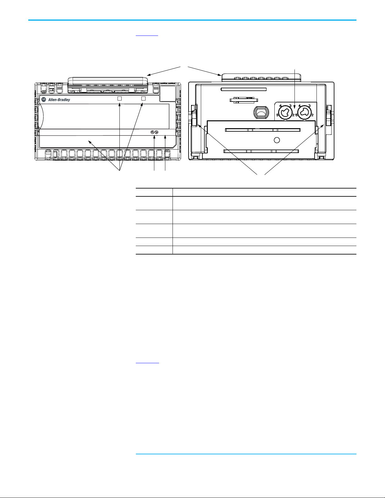
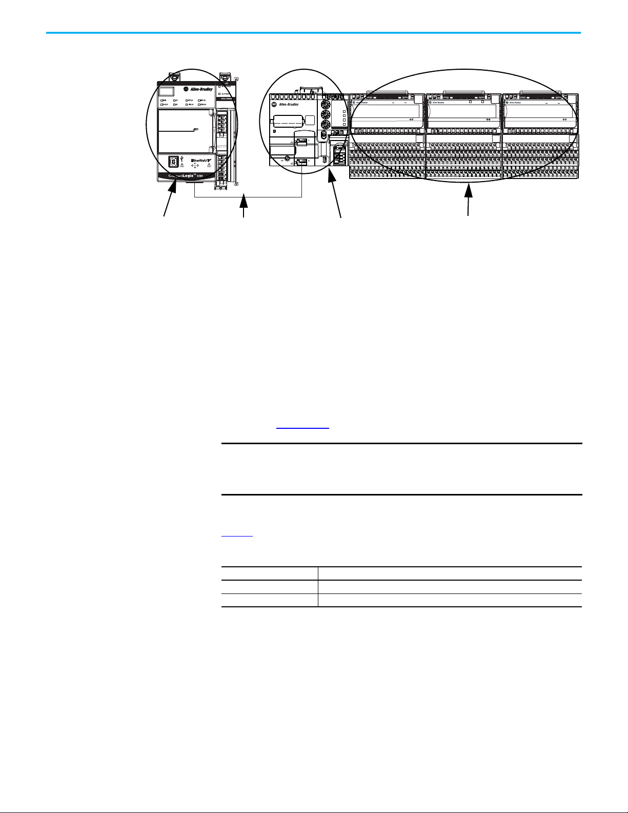
Module Overview Figure 1 shows the parts of an example FLEX 5000 analog HART I/O module.
Figure 1 - Example FLEX 5000 Analog HART I/O Module
Item Description
1
2
3
4 Ter min al b ase - Indicates the type of terminal base assembly to use with the module.
5 Latching hooks - Securely installs FLEX 5000 modules on the terminal base assembly.
Status indicators - Displays the status of communication, module health, and input/output
devices. Indicators help with troubleshooting anomalies.
Release lever - Disengages the latching hooks to allow removal of the module from the
terminal base assembly.
Module keying - Indicates the keying position the terminal base assembly must be configured
to before installing the module.
HART Communication The HART field communication protocol is widely accepted in industry as a
standard for digitally enhanced 4…20 mA communication with smart
(microprocessor-based) field devices. A digital signal is superimposed on the
4…20 mA current loop to provide two means of communication from the
device. The 4…20 mA analog channel lets the primary process variable be
communicated at the fastest possible rate while the digital channel
communicates multiple process variables, data quality, and device status. The
HART protocol lets these simultaneous communication channels be used in a
complementary fashion.
(1)
shows information about the HART protocol.
Figure 2
(1) This figure is from the HART Communication Protocol Specifications, April 2001, Revision
Rockwell Automation Publication 5094-UM007B-EN-P - October 2020 13
6.0, HART Communication Foundation. All Rights Reserved.
Page 14
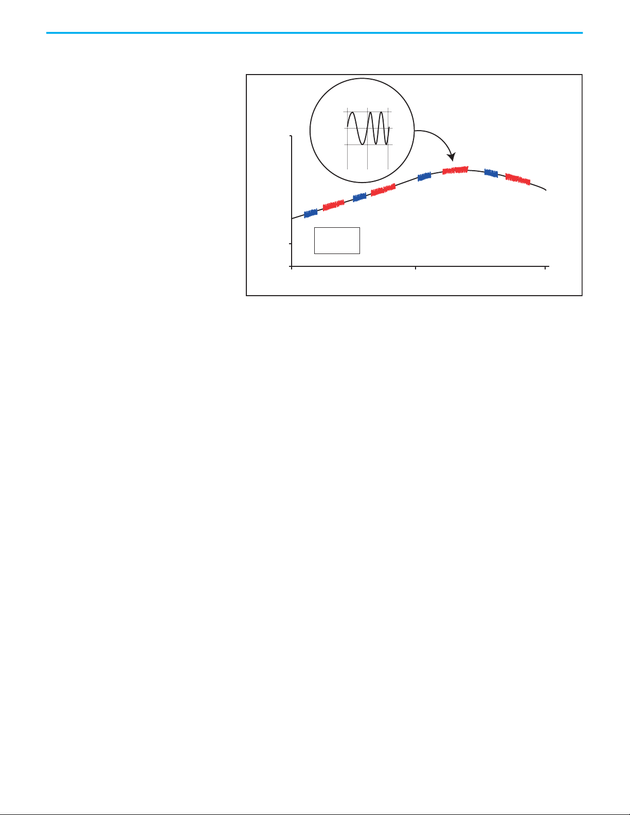
Chapter 1 FLEX 5000 HART I/O Modules
The Highway Addressable Remote Transducer (HART)
protocol supports two-way digital communication,
complements traditional 4…20 mA analog signals, and
includes the following features:
• Predefined commands
– Universal command
–Common practice
– Device specific
• Large installed base
• Worldwide support
Figure 2 - HART Protocol
20 mA
Analog
Signal
4 mA
c
+0.5 mA
0.5 mA
R
Analog
Signal
0
2200
1200
Hz
Hz
“0”
“1”
R
c
HART Signal
c
R
= Command
c
= Response
R
c
R
01 2
Time (seconds)
FLEX 5000 analog HART I/O modules support the HART protocol and perform
these operations:
• Conversion of 4…20 mA analog signals to digital numeric values in
engineering units (such as kg, m, or percent) that are used in the Logix
controller.
• Conversion of digital numeric values in engineering units to 4…20 mA
analog signals to control process devices.
• Producer/Consumer network communication model directly to each
HART device.
• Automatic collection of dynamic process data from the connected HART
device. For example, temperature, pressure, flow, or valve position.
• Automatic collection of device-specific variables from the connected
HART device.
• Execution of commands through Studio 5000 Logix Designer using
input and output tags.
• Facilitation of configuration and troubleshooting of the HART field
device from your control room using FDT/DTM supported software.
With the FLEX 5000 analog HART I/O modules, both the controller and
software for device maintenance and management can access field device
data.
14 Rockwell Automation Publication 5094-UM007B-EN-P - October 2020
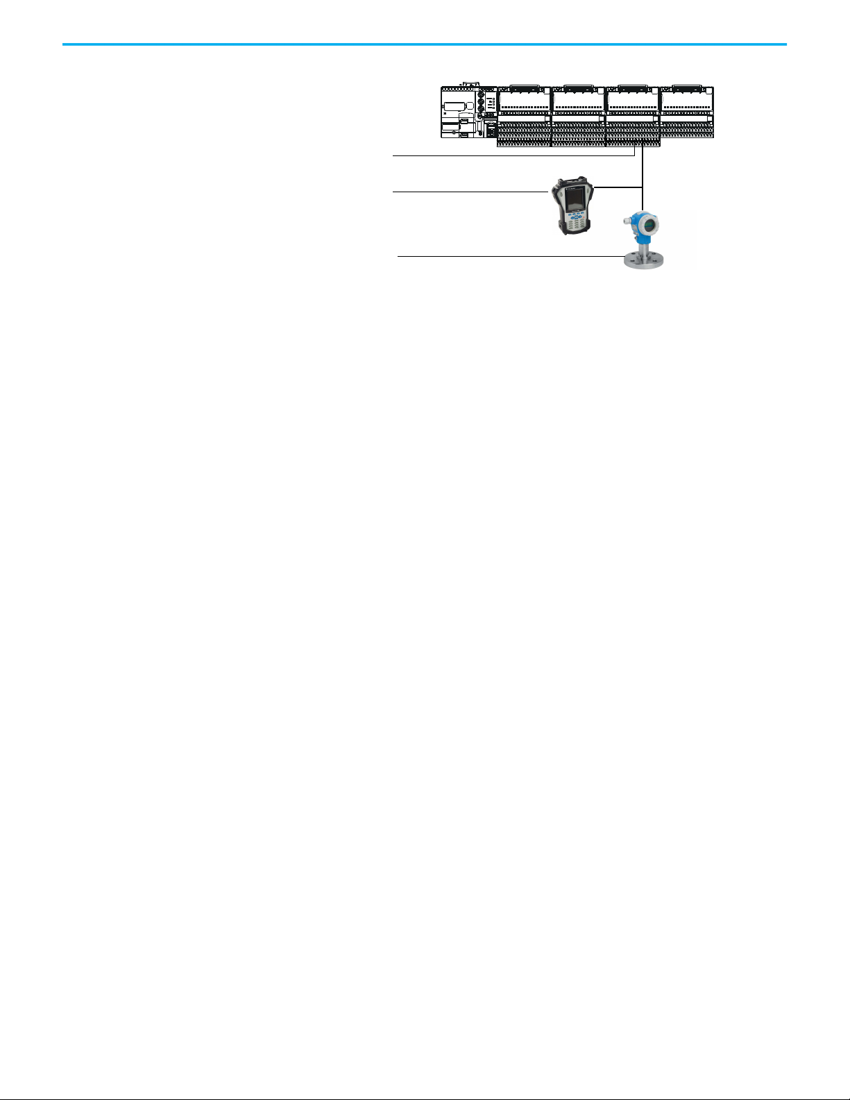
The FLEX 5000 analog HART I/O modules support command-response
communication protocol in a point-to-point wiring architecture.
The FLEX 5000 analog HART I/O module is the primary master device and
continuously obtains information from the connected HART devices. The
secondary master can be used for device maintenance, for example a handheld
communicator, as shown here.
Page 15
Chapter 1 FLEX 5000 HART I/O Modules
Primary master
Secondary master
(handheld communicator
as secondary master)
Slave
Most 4…20 mA transmitters are available with a HART protocol interface. The
type of data available depends on the type of instrument.
An example application is a HART enabled mass flowmeter. The standard mA
signal from the flowmeter provides one primary measurement - flow. The mA
signal with HART provides more process information. The mA signal that
represents flow is still available. The HART configuration of the flowmeter can
be set to communicate primary variable (PV), secondary variable (SV), tertiary
variable (TV), and quaternary variable (QV). These values can represent mass
flow, static pressure, temperature, total flow, and other conditions.
Dynamic variables, device-specific variables, device status, and command
execution are all available through input and output controller tags in Studio
5000 Logix Designer.
Device status information is also provided through HART.
HART connectivity provides all this information with no changes to the
existing 4…20 mA wiring.
FDT/DTM technology through HART connectivity is supported and also
provides remote configuration and troubleshooting of HART devices through
software.
HART-enabled I/O Modules
The FLEX 5000 analog HART I/O modules have built-in HART modems, so
there is no need to install external HART multiplexers or clip-on HART
modems. The 5094-IF8IH, 5094-OF8IHXT, 5094-OF8IH, and 5094-OF8IHXT
modules have separate HART modems for each channel.
HART implementation in 5094 provides a connection between the controller
and each HART device.
A HART device that is configured in a 5094 I/O module supports a configurable
connection that can include up to four Dynamic Variables, eight Device
Variables, and four HART Commands.
Rockwell Automation Publication 5094-UM007B-EN-P - October 2020 15
Page 16

Chapter 1 FLEX 5000 HART I/O Modules
Notes:
16 Rockwell Automation Publication 5094-UM007B-EN-P - October 2020
Page 17

Chapter 2
Analog HART I/O Module Operation in a Logix
5000 Control System
Top ic Pa ge
Remote I/O Modules 17
Before You Begin 18
Types of Analog I/O Modules 18
Power the Modules 18
Ownership 19
Configure Analog HART I/O Modules 20
Input Module Operation 23
Output Module Operation 23
HART Device Operation 26
Listen Only Mode 25
Protected Operations 26
IMPORTANT
Remember the following when you use FLEX 5000 Analog HART
I/O Modules:
• You cannot use FLEX 5000 I/O modules with all Logix 5000 controllers.
For example, you can use FLEX 5000 I/O modules with
CompactLogix 5380 and ControlLogix 5580 controllers but not with
CompactLogix 5370 and ControlLogix 5570 controllers.
For the most current information on the Logix 5000 controllers with
which you can use FLEX 5000 I/O modules, see the product
description at rok.auto/flex5000IO
• You must use the Studio 5000 Logix Designer application, version
32.02 or later, to configure the FLEX 5000 analog HART I/O modules.
• You must use the Studio 5000 Logix Designer application, version
33.00 or later, to support ControlLogix 5580 High Availability
controllers.
.
Remote I/O Modules You use FLEX 5000 analog HART I/O modules as remote I/O modules that are
accessible via an EtherNet/IP network. The modules are installed to the right
of a FLEX 5000 EtherNet/IP adapter.
Logix 5000 controllers can exchange data with the modules over the network.
Rockwell Automation Publication 5094-UM007B-EN-P - October 2020 17
Page 18
Chapter 2 Analog HART I/O Module Operation in a Logix 5000 Control System
5069-L340ERM
EtherNet/IP Network
5094 I/O with shield bar
5094-AENTR
Figure 3 - FLEX 5000 I/O Modules in a Logix 5000 Control System
IP ADDRESS
POWER
X100
FLEX 5000TM I/O
EtherNet/IP™ Adapter
X10
STATUS
NET
LINK 1
X1
LINK 2
5094-AENTR
PRP
DLR
FLEX 5000TM I/O
ANALOG 8 OUTPUT HART ISOLATED
5094-OF8IH
0 1 2 3 4 5 6 7
STATUS
POWER
2
3
TB3I
FLEX 5000TM I/O
ANALOG 8 INPUT HART ISOLATED
5094-IF8IH
0 1 2 3 4 5 6 7
STATUS
POWER
3
5
TB3I
FLEX 5000TM I/O
ANALOG 8 OUTPUT HART ISOLATED
5094-OF8IHXT
0 1 2 3 4 5 6 7
Before You Begin Before you use your analog HART I/O module, you must complete the
following:
a. Install a FLEX 5000 EtherNet/IP adapter.
b. Install the FLEX 5000 I/O modules to the right of adapter.
c. Install an EtherNet/IP network.
d. Install the Logix 5000 controller that accesses the FLEX 5000 I/O
modules via an EtherNet/IP network.
Make sure that you have enough FLEX 5000 terminal base (TB) assemblies to
satisfy your application needs. For more information, see the FLEX 5000
Terminal Base Assembly Modules Installation Instructions,
publication 5094-IN010
.
STATUS
POWER
2
3
TB3I
IMPORTANT
TBs are not included with your module and are not available for
purchase. TBs consist of a mounting base (MB) and removable terminal
block (RTB). You must purchase MBs and RTBs separately and assemble
them together.
Types of Analog I/O Modules
Ta b l e 3 describes the types of FLEX 5000 analog HART I/O modules.
Table 3 - FLEX 5000 Analog HART I/O Modules
Cat. No. Description
5094-IF8IH, 5094-IF8IHXT 8-channel isolated current/voltage/HART input module
5094-OF8IH, 5094-OF8IHXT 8-channel isolated current/voltage/HART output module
Power the Modules FLEX 5000 analog HART I/O modules receive the following power types:
• System-side power that powers the system and lets modules transfer
data and execute logic. System-side power is also known as Backplane
power.
• Field-side power that powers field-side devices that are connected to
some FLEX 5000 I/O modules. Field-side power is also known as
SA power.
18 Rockwell Automation Publication 5094-UM007B-EN-P - October 2020
Page 19

Chapter 2 Analog HART I/O Module Operation in a Logix 5000 Control System
System-side power begins at the FLEX 5000 EtherNet/IP adapter and passes
across the FLEX 5000 module internal circuitry via terminal base power bus,
that is, Backplane power.
Field-side power, that is, SA power begins at the first terminal base assembly
and can be daisy chained to the next terminal base assembly on the right. You
can also install a separate field-side power source to each terminal base
assembly.
For more information on how to power FLEX 5000 analog HART I/O modules,
see the FLEX 5000 EtherNet/IP Adapter User Manual, publication 5094-
UM005.
SA Power Requirements
Take note of the following when supplying SA power to your system:
• You must limit the SA field-side power source to 10 A, max, at
18...32V DC.
• Confirm that the external module power supply is adequately sized for
the total module power bus current draw in the system.
• For example, if the total module power current draw, including current
inrush requirements, is 5 A, you can use a module power supply that is
limited to 5 A.
• You must use SELV-listed power supplies for module power if there are
functional safety modules that are connected to the FLEX 5000 I/O
family.
• Not all power supplies are certified for use in all applications, for
example, nonhazardous and hazardous environments.
• Isolated source power of up to 25 mA available from the module to
simplify the channel to channel isolation wiring for current sensors.
IMPORTANT
We recommend that you use separate external power supplies for the
adapter and the adjacent terminal base. This practice can prevent
unintended consequences that can result if you use one supply.
Ownership Every I/O module in a Logix 5000 control system must be owned by a
controller, also known as the owner-controller. When the FLEX 5000 Analog
HART I/O modules are used in a Logix 5000 control system, the ownercontroller performs the following:
• Stores configuration data for every module that it owns.
• Can reside in a location that differs from the FLEX 5000 I/O modules.
• Sends the I/O module configuration data to define module behavior and
begin operation in the control system.
Each FLEX 5000 Analog HART I/O module must continuously maintain
communication with its owner-controller during normal operation.
FLEX 5000 Analog HART I/O modules are limited to one owner-controller.
Rockwell Automation Publication 5094-UM007B-EN-P - October 2020 19
Page 20

Chapter 2 Analog HART I/O Module Operation in a Logix 5000 Control System
Configure Analog HART I/O Modules
You must create a Studio 5000 Logix Designer application project for the
Logix 5000 controller that owns the FLEX 5000 analog HART I/O modules and
attached HART devices. The project includes module configuration data for
the FLEX 5000 Analog HART I/O modules.
The Studio 5000 Logix Designer application transfers the project to the ownercontroller during the program download. Data is then transferred to the
FLEX 5000 analog HART I/O modules over the EtherNet/IP network.
The FLEX 5000 analog HART I/O modules can operate immediately after
receiving the configuration data.
Connections
During module configuration, you must define the module. Among the
Module Definition parameters, you must choose a connection type for the
module. A connection is a real-time data transfer link between the ownercontroller and the module that occupies the slot that the configuration
references.
During HART device configuration, you must define the input and output tags
for any connected HART device.
When you download module configuration to a controller, the controller
attempts to establish a connection to each module in the configuration.
Because part of module configuration includes a slot in the FLEX 5000 I/O
system, the owner-controller checks for the presence of a module or connected
HART device there. If a module or HART device is detected, the ownercontroller sends the configuration. One of the following occurs:
• If the configuration is appropriate to the module or HART device that is
detected, a connection is made and operation begins.
• If the configuration is not appropriate to the module or HART device that
is detected, the data is rejected and the Studio 5000 Logix Designer
application indicates that an error occurred.
The configuration can be inappropriate for many reasons. For example, a
mismatch in electronic keying that helps prevents normal operation.
The owner-controller monitors its connection with a module and HART
devices. Any break in the connection, for example, the loss of power to the
FLEX 5000 I/O system, causes a fault. The Studio 5000 Logix Designer
application monitors the fault status tags to indicate when a fault occurs on a
module or HART device.
Connection Types Available with FLEX 5000 Analog HART I/O Modules
When configuring an analog HART input or output module, you must define
the module. Connection is a required parameter in the Module Definition. The
choice determines what data is exchanged between the owner-controller and
the module.
20 Rockwell Automation Publication 5094-UM007B-EN-P - October 2020
Page 21

Chapter 2 Analog HART I/O Module Operation in a Logix 5000 Control System
For more information on configuring the I/O modules, see Configure the
Module on page 71.
Table 4
describes the connection types that you can use with FLEX 5000 analog
HART I/O modules.
Table 4 - Connections - HART I/O Modules
Description
Connection Type
Data
Listen Only
HART Input Modules HART Output Modules
The module returns the following to the
owner-controller:
General fault data
Input data
When a Listen Only data connection is used, another controller owns the module.
A controller that makes a Listen Only connection to the module does not write
configuration for the module. It merely listens to the data exchanged with the ownercontroller.
IMPORTANT: If a controller uses a Listen Only connection, the connection must use the
Multicast option.
For more information on Listen Only connections, see Listen Only Mode
this case, all other connections to the module, for example, the connection to the
owner-controller must also use the Multicast option.
The module returns the following to the
owner-controller:
General fault data
Output data
on page 25. In
Data Types Available with FLEX 5000 Analog HART I/O Modules
The Module Definition includes a Data parameter that matches the module
type. Input modules use Input Data, and output modules use Output Data.
The available Data parameter choices are as follows:
• 5094-IF8IH and 5094-IF8IHXT – The Input Data choice is either Analog,
Analog and Discrete, or Discrete.
• 5094-OF8IH and 5094-OF8IHXT – The Output Data choice is always
Analog.
For more information on the Connection and Data parameter choices
available with FLEX 5000 I/O modules, see the Studio 5000 Logix Designer
application.
Requested Packet Interval
The Requested Packet Interval (RPI) is a configurable parameter that defines a
specific rate at which data is exchanged between the owner-controller and the
module.
You set the RPI value during initial module configuration and can adjust it as
necessary after module operation has begun. Valid RPI values for analog HART
I/O modules are 0.2…750 ms. Valid RPI values for HART devices are
500…9999.9 ms.
Rockwell Automation Publication 5094-UM007B-EN-P - October 2020 21
Page 22

Chapter 2 Analog HART I/O Module Operation in a Logix 5000 Control System
IMPORTANT
If you change the RPI while the project is online, the connection to the
module is closed and reopened in one of the following ways:
• You inhibit the connection to the module, change the RPI value, and
uninhibit the connection.
• You change the RPI value. In this case, the connection is closed and
reopened immediately after you apply the change to the module
configuration.
For more information on guidelines for specifying RPI rates, see the
Logix 5000 Controllers Design Considerations Reference Manual, publication
1756-RM094
.
Connection Over an EtherNet/IP Network
During module and connected HART device configuration, you must
configure the Connection over EtherNet/IP parameter. The configuration
choice dictates how input data is broadcast over the network.
The FLEX 5000 analog HART I/O modules use one of the following methods to
broadcast data:
• Multicast - Multicast connections deliver information from one sender
to multiple receivers simultaneously.
Copies of one transmission are passed to a selected subset of possible
destinations.
• Unicast - Unicast connections are point-to-point transmissions between
a source node and destination node on the network.
A transmission is sent to one destination controller depending on the
module configuration.
Unicast is the default setting. We recommend that you use Unicast because it
reduces network bandwidth usage. However, if you are using a ControlLogix
5580 High Availability controller, you must use multicast.
Multicast is more efficient than sending multiple unicast streams to multiple
notes. Use multicast in the following situations:
• FLEX 5000 I/O is used in a Redundancy application
• Communication is with multiple destinations
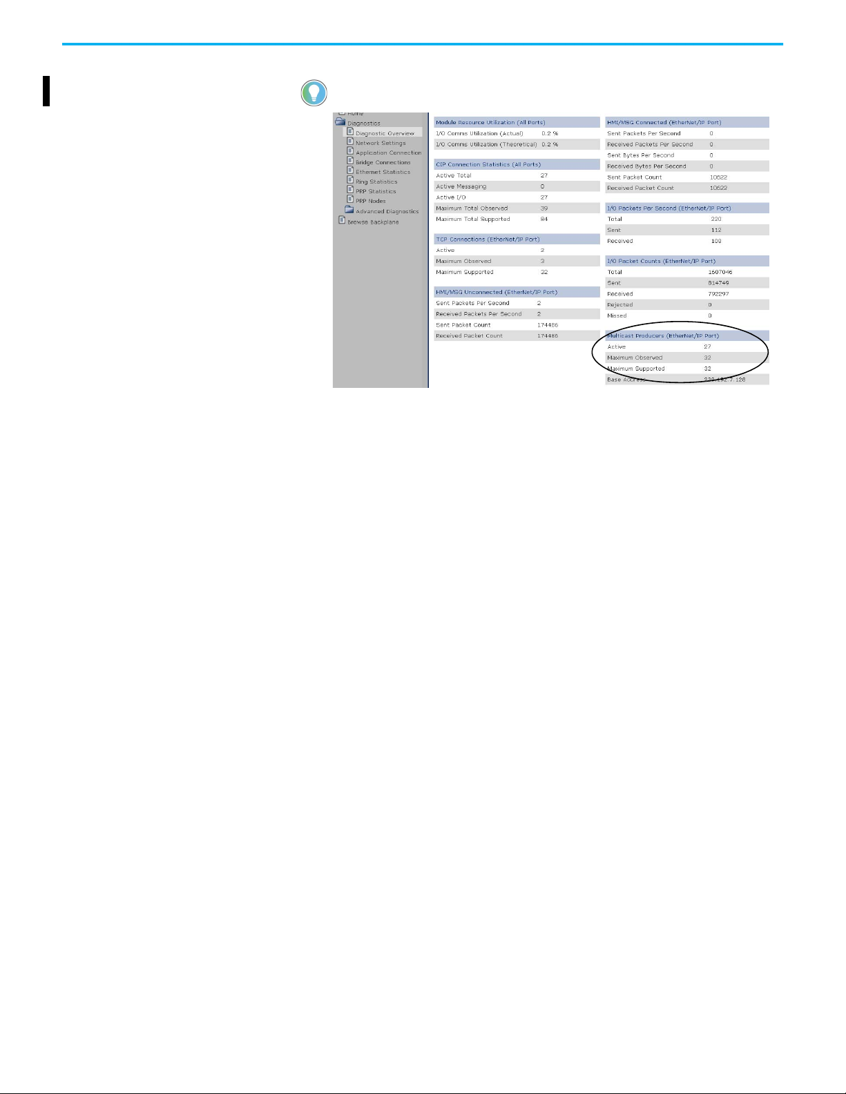
IMPORTANT When using a ControlLogix 5580 High Availability controller, a HART
modules occupies 1 multicast connection and HART devices occupy up
to 4 multicast connections. These connections total a maximum of 5
connections per HART module and limits the adapter to a maximum of 6
HART modules.
22 Rockwell Automation Publication 5094-UM007B-EN-P - October 2020
Page 23
Chapter 2 Analog HART I/O Module Operation in a Logix 5000 Control System
You can verify how many multicast connections are on your network by looking at
your adapter Diagnostic Overview web page.
Input Module Operation Logix 5000 controllers do not poll the FLEX 5000 analog input modules for
input data. Instead, the input modules send their input data, that is channel
and status data, at the RPI.
At the RPI, not only does the module send input data to the controller, but also
the controller sends data to the module inputs. For example, the controller
sends data to command the module to unlatch alarms or enable alarms.
FLEX 5000 analog input modules reside in a FLEX 5000 I/O system that is
accessible to a Logix 5000 controller over an EtherNet/IP network. A
FLEX 5000 EtherNet/IP adapter is the first component in a FLEX 5000 I/O
system and connects the system to the EtherNet/IP network.
FLEX 5000 analog input modules communicate input data to the FLEX 5000
EtherNet/IP adapter at the defined RPI. The input data consists of channel and
status data.
At the RPI, the following events occur.
1. The remote analog input module scans its channels for input data.
2. The module sends the data to the FLEX 5000 EtherNet/IP adapter.
3. The FLEX 5000 EtherNet/IP adapter in the FLEX 5000 I/O system sends
the data over the EtherNet/IP network.
4. One of the following:
• If the controller is directly connected to the EtherNet/IP network, it
receives the input data immediately.
• If the controller is connected to the EtherNet/IP network through
another communication module, the module sends the data to its
backplane and the controller receives it.
Output Module Operation The controller sends data to an output module at the RPI or after an
Immediate Output (IOT) instruction is executed.
Rockwell Automation Publication 5094-UM007B-EN-P - October 2020 23
Page 24

Chapter 2 Analog HART I/O Module Operation in a Logix 5000 Control System
The RPI defines when the controller sends data to the FLEX 5000 analog
output module and when the output module reads back data. The controller
sends data to an output module only at the RPI.
At the RPI, not only does the controller send data to the output module, but
also the output module sends data to the controller. For example, the output
module sends an indication of the channel data quality.
FLEX 5000 analog input modules reside in a FLEX 5000 I/O system that is
accessible to a Logix 5000 controller over an EtherNet/IP network. A
FLEX 5000 EtherNet/IP adapter is the first component in a FLEX 5000 I/O
system and connects the system to the EtherNet/IP network.
FLEX 5000 analog output modules receive output data from a controller. The
output module also sends data to the controller.
Controller to Remote Analog Output Module Data Transmission
The controller broadcasts data to its local backplane at one of the following:
•RPI
• An IOT instruction is executed.
IMPORTANT
An IOT instruction sends data to all output modules in the system
immediately, and resets the RPI timer.
Based on the RPI rate and the length of the controller program scan, the output
module can receive and readback data multiple times during one program
scan.
When the RPI is less than the program scan length, the output channels can
change values multiple times during a program scan. The owner-controller
does not depend on the program scan to complete to send data.
These events occur when the controller sends data to a FLEX 5000 output
module.
1. Data is sent in one of the following ways:
• If the controller is directly connected to the EtherNet/IP network, it
broadcasts data to the network.
In this case, skip to step 3
.
• If the controller is connected to the EtherNet/IP network via a
communication module, the controller transmits the data to the
backplane.
In this case, proceed to step 2.
2. The EtherNet/IP communication module transmits the data to the
EtherNet/IP network.
3. The FLEX 5000 EtherNet/IP adapter in the FLEX 5000 I/O system
receives the data from the network and transmits it to the backplane.
4. The remote analog output module receives the data from the backplane
and behaves as dictated by its configuration.
24 Rockwell Automation Publication 5094-UM007B-EN-P - October 2020
Page 25

Chapter 2 Analog HART I/O Module Operation in a Logix 5000 Control System
Remote Analog Output Module to Controller Data Transmission
When a FLEX 5000 analog output module receives new data and the requested
data value is present on the RTB, the output module sends, or reads back a data
value back to the controller and to the rest of the control system. The data value
corresponds to the signal present at its terminals. This feature is called Output
Readback.
In addition to the Output Readback, the output module sends other data to the
controller at the RPI. For example, the module alerts the controller if a short
circuit condition exists on the module.
The following events occur when a remote FLEX 5000 analog output module
sends data to the controller at the RPI.
1. The module sends the data to the backplane.
2. The FLEX 5000 EtherNet/IP adapter in the FLEX 5000 I/O system sends
the data over the EtherNet/IP network.
3. One of the following:
• If the controller is directly connected to the EtherNet/IP network, it
receives the input data from the network without need for a
communication module.
• If the controller is connected to the EtherNet/IP network through
another communication module, the module transmits the data to its
backplane and the controller receives it.
Listen Only Mode Any controller in the system can listen to the data from an I/O module. An
owner-controller, as described in Ownership
analog I/O modules.
Other controllers can use a Listen Only connection with the analog I/O
module. In this case, the ‘listening’ controller can only listen to input data or
output readback data. The listening controller does not own the module
configuration or exchange other data with the module.
During the I/O configuration process, you can specify a Listen Only
connection. For more information on Connection options, see Input Module
Definition on page 76.
IMPORTANT
Remember the following:
• If a controller uses a Listen Only connection, the connection must use
the Multicast option. In this case, all other connections to the module,
for example, the connection of the owner-controller, must also use the
Multicast option.
• If a controller attempts to use a Listen Only connection to a module but
the owner-controller connection uses the Unicast option, the attempt at
a Listen Only connection fails.
The ‘Listen Only’ controller receives data from the module as long as a
connection between an owner-controller and module is maintained.
• If the connection between an owner-controller and the module is
broken, the module stops sending data and connections to all ‘listening
controllers’ are also broken.
• Connected HART devices cannot be added to Listen Only connections.
on page 19, exchanges data with
Rockwell Automation Publication 5094-UM007B-EN-P - October 2020 25
Page 26
Chapter 2 Analog HART I/O Module Operation in a Logix 5000 Control System
Protected Operations To maintain the secure operation of your FLEX 5000 analog HART I/O module,
operations that can disrupt module operation are restricted based on the
module operating mode. Table 5
Table 5 - Protected Operations on FLEX 5000 Analog HART I/O Modules
Current Module Operation
Connection not running Accepted
Connection running
Firmware update is in process Rejected
Calibration is in process
(1) A module calibration request is accepted when the module is connected and the owner-controller is in Program mode.
(2) The module accepts the requests and changes listed. Keep in mind, when the request or change is made, the calibration process is automatically aborted. We recommend that you wait for
the module calibration to finish before attempting any of the requests or changes.
(3) When the request is made through the Module Properties dialog box.
(4) Only requests for Listen Only connections are accepted.
(5) Configuration change is accepted in the following scenarios:
- Changes are made in the Module Properties dialog box and you click Apply.
- Changes are made in the Configuration tags and you send a Reconfigure Module MSG to the module.
(6) The difference between Rejected and Not allowed is that rejected activities can be attempted in the Studio 5000 Logix Designer application but do not take effect. The activities that are not
allowed, that is, attempts to change the Connection or Data Format used, do not occur in the Studio 5000 Logix Designer application.
For example, if you attempt to reset a module that is connected to the owner-controller, the Studio 5000 Logix Designer application executes the request and alerts you that it was rejected.
If you attempt to change the data format on a module that is connected to an owner-controller, the Studio 5000 Logix Designer application does not execute the attempted change. The
application only alerts you that the change is not allowed. In the case, if the change is attempted online, the Module Definition dialog box field that changes the data format is disabled.
(7) The change occurs after the connection is closed and reopened. You can close and reopen the connection in the following ways:
- Change the project while it is offline and download the updated project before going online again.
- Change the project while it is online and click Apply or OK in the Module Properties dialog box. In this case, before the change is made, a dialog box alerts you of the ramifications before
the change is made.
Firmware
Update
Request
Rejected
Accepted
Module Reset
Request
(1)
(2)
Module
Calibration
(3)
Request
Connection
Request
Accepted
describes the restrictions.
Activity
Configuration
Change
(4)
Accepted
(5)
Connection or
Data Format
Change
Not allowed
(6)
Electronic
Keying
Change
Accepted
RPI Change
(7)
HART Device Operation Before using the HART capabilities, be sure that:
• the I/O module and the associated field device are working properly in
the analog 4…20 mA mode.
• the channel is configured as 4…20 mA range with HART enabled.
• the field device is HART capable.
• no more than one HART field device is connected to each channel.
• Notch Filter of input channel or Ramping Rate of output channel is set to
a valid value.
Input data of HART device, that is device status, dynamic, or device variable
values and status, are sent to Logix Controller at the RPI.
At the RPI, not only does the module send input data of the HART devices to
the controller, but also the controller sends data for the HART devices to the
module. For example, the controller sends data to reset Configuration
Changed status or initiate an execution of a pre-configured HART command.
IMPORTANT If you switch the controller to Program mode or inhibit an output
module, it may cause the output channels to de-energize and the HART
device to not power up.
To power up the HART device, switch the controller to Run mode and
uninhibit the output module.
26 Rockwell Automation Publication 5094-UM007B-EN-P - October 2020
Page 27

Chapter 2 Analog HART I/O Module Operation in a Logix 5000 Control System
Protected Operations for HART Devices
To maintain the secure operation of your HART device, operations that can
disrupt module operation are restricted based on the module operating mode.
Table 6
describes the restrictions.
Table 6 - Protected Operations on HART Devices
Activity
Current Module Operation
Connection not running Accepted
Connection running Rejected
(1) Device Configuration change is accepted if changes are made using FTD/DTM, handheld device, and HART commands.
(2) The difference between Rejected and Not allowed is that rejected activities can be attempted in the Studio 5000 Logix Designer application but do not take effect. The activities that are not
allowed, that is, attempts to change the Connection or Data Format used, do not occur in the Studio 5000 Logix Designer application.
For example, if you attempt to reset a module that is connected to the owner-controller, the Studio 5000 Logix Designer application executes the request and alerts you that it was rejected.
If you attempt to change the data format on a module that is connected to an owner-controller, the Studio 5000 Logix Designer application does not execute the attempted change. The
application only alerts you that the change is not allowed. In the case, if the change is attempted online, the Module Definition dialog box field that changes the data format is disabled.
(3) The change occurs after the connection is closed and reopened. You can close and reopen the connection in the following ways:
- Change the project while it is offline and download the updated project before going online again.
- Change the project while it is online and click Apply or OK in the Module Properties dialog box. In this case, before the change is made, a dialog box alerts you of the ramifications before the
change is made.
- RPI changes applied to one channel applies the same change to all channels in the configuration section.
Device Reset
Request
Connection
Request
Device Configuration
Change
(1)
Accepted
Device Connection or
Data Format Change
Not allowed
(2)
Electronic Keying
Change
(3)
Accepted
RPI Change
Rockwell Automation Publication 5094-UM007B-EN-P - October 2020 27
Page 28

Chapter 2 Analog HART I/O Module Operation in a Logix 5000 Control System
Notes:
28 Rockwell Automation Publication 5094-UM007B-EN-P - October 2020
Page 29

Chapter 3
Common I/O Module Features
Top ic Pa ge
Software Configurable 29
Fault and Status Reporting 30
Module Inhibiting 30
Electronic Keying 31
Producer/Consumer Communication 31
Status Indicators 32
Use CIP Sync Time with I/O Modules 32
Module Firmware 32
Common Analog Channel Features 33
This chapter describes module features that are available on both FLEX 5000
HART input and output modules.
FLEX 5000 analog HART input modules convert an analog signal to a digital
value. For example, the modules can convert the following:
•Volts
•Milliamps
You can configure FLEX 5000 HART input modules to support digital input
signals when your application requires channel to channel isolation. The
following types of discrete device types are supported:
• Digital Input
• IEC 61131-2 Type 3-d Digital Input
For information on digital input points, see Chapter 5
FLEX 5000 analog HART output modules convert a digital value to an analog
signal. For example, the modules can convert the following:
•Volts
•Milliamps
FLEX 5000 analog HART enabled modules decodes HART information from
signal embedded within the channel.
Software Configurable You use the Studio 5000 Logix Designer application to configure the module,
monitor system operation, and troubleshoot issues. You can also use the
Studio 5000 Logix Designer application to retrieve the following information
from any module in the system:
• Serial number
Rockwell Automation Publication 5094-UM007B-EN-P - October 2020 29
Page 30

Chapter 3 Common I/O Module Features
• Firmware revision information
• Product code
•Vendor
• Error and fault information
• Diagnostic information
By minimizing the need for tasks, such as setting hardware switches and
jumpers, the software makes module configuration easier and more reliable.
Fault and Status Reporting The FLEX 5000 analog HART I/O modules report fault and status data along
with channel data. Fault and status data is reported in the following ways:
• Studio 5000 Logix Designer application
• Module status indicators
For more information on fault reporting, see the individual module feature
chapters and Appendix A, Troubleshoot Your Module
on page 107.
Module Inhibiting Module inhibiting lets you indefinitely suspend a connection, including Listen
Only connections, between an owner-controller and an analog I/O module
without removing the module from the configuration. This process lets you
temporarily disable a module, such as to perform maintenance.
IMPORTANT
You can use module inhibiting in the following ways:
• You write a configuration for an I/O module but inhibit the module to
help prevent it from communicating with the owner-controller. The
owner does not establish a connection and the configuration is not sent
to the module until the connection is uninhibited.
• In your application, a controller already owns a module, has downloaded
the configuration to the module, and is exchanging data over the
connection between the devices.
You can use module inhibiting in these instances:
• You want to update an analog I/O module, for example, update the
module firmware revision. Use the following procedure.
a. Inhibit the module.
b. Perform the update.
c. Uninhibit the module.
• You use a program that includes a module that you do not physically
possess yet. You do not want the controller to look for a module that does
not yet exist. In this case, you can inhibit the module in your program
until it physically resides in the proper slot.
Once a module is inhibited, the connections to the module and attached
HART devices are also closed and the CIP messaging to the HART
devices is disabled.
To see where to inhibit a FLEX 5000 analog HART I/O module, see page 77
30 Rockwell Automation Publication 5094-UM007B-EN-P - October 2020
.
Page 31

Chapter 3 Common I/O Module Features
Electronic Keying Electronic Keying reduces the possibility that you use the wrong device in a
control system. It compares the device that is defined in your project to the
installed device. If keying fails, a fault occurs. These attributes are compared.
Attribute Description
Vendor The device manufacturer.
Device Type The general type of the product, for example, analog I/O module.
Product Code The specific type of the product. The Product Code maps to a catalog number.
Major Revision A number that represents the functional capabilities of a device.
Minor Revision A number that represents behavior changes in the device.
The following Electronic Keying options are available.
Keying Option Description
Lets the installed device accept the key of the device that is defined in the project when the
installed device can emulate the defined device. With Compatible Module, you can typically
replace a device with another device that has the following characteristics:
Same catalog number
Compatible Module
Disable Keying
Exact Match
Same or higher Major Revision
Minor Revision as follows:
If the Major Revision is the same, the Minor Revision must be the same or higher.
If the Major Revision is higher, the Minor Revision can be any number.
Non-XT and XT version as follows:
You can use an XT version of the module in place of a non-XT module.
You cannot use a non-XT version of the module in place of an XT module.
Indicates that the keying attributes are not considered when attempting to communicate
with a device. With Disable Keying, communication can occur with a device other than the
type specified in the project.
WAR N IN G : Be extremely cautious when using Disable Keying; if used incorrectly, this option
can lead to personal injury or death, property damage, or economic loss.
We strongly recommend that you do not use Disable Keying.
If you use Disable Keying, you must take full responsibility for understanding whether the
device being used can fulfill the functional requirements of the application.
Indicates that all keying attributes must match to establish communication. If any attribute
does not match precisely, communication with the device does not occur.
Producer/Consumer Communication
Carefully consider the implications of each keying option when selecting one.
IMPORTANT Changing Electronic Keying parameters online interrupts connections to the
device and any devices that are connected through the device. Connections
from other controllers can also be broken.
If an I/O connection to a device is interrupted, the result can be a loss of data.
More Information
For more detailed information on Electronic Keying, see Electronic Keying in
Logix 5000 Control Systems Application Technique, publication
LOGIX-AT001
FLEX 5000 analog HART I/O modules use the Producer/Consumer
communication model to produce data without a controller polling them first.
The modules produce the data and controllers consume it. That is, the ownercontroller and controllers with a Listen Only connection to the module can
consume it.
.
Rockwell Automation Publication 5094-UM007B-EN-P - October 2020 31
Page 32

Chapter 3 Common I/O Module Features
When an input module produces data, the controllers can consume the data
simultaneously. Simultaneous data consumption eliminates the need for one
controller to send the data to other controllers.
IMPORTANT
Keep in mind, only one controller can own the I/O module. The
FLEX 5000 analog I/O modules do not support multiple owners of the
same module.
Other controllers must use a Listen Only connection to the module.
Status Indicators Each FLEX 5000 analog HART I/O module has a status indicator on the front
of the module that lets you check the health and operational status of a module.
The status indicator displays vary for each module.
For more information on status indicators, see Appendix A, Troubleshoot Your
Module on page 107.
Use CIP Sync Time with I/O Modules
CIP Sync™ is a CIP™ implementation of the IEEE 1588 PTP (Precision Time
Protocol). CIP Sync provides accurate real-time (Real-World Time) or
Universal Coordinated Time (UTC) synchronization of controllers and devices
that are connected over CIP networks. This technology supports highly
distributed applications that require timestamping, sequence of events
recording, distributed motion control, and increased control coordination.
The 5094-IF8IH module is a CIP Sync slave-only device. There must be another
module on the network that functions as a master clock. For more information
on how to use CIP Sync technology, see the Integrated Architecture® and CIP
Sync Configuration Application Technique, publication IA-AT003
.
I/O modules can be used to capture timestamps. The advantage is that CIP
Sync is system-wide, so timestamp values are consistent across all modules in
the system.
Module Firmware The FLEX 5000 analog HART I/O modules are manufactured with module
firmware installed. If updated module firmware revisions are available in the
future, you can update the firmware.
Updated firmware revisions are made available for various reasons, for
example, to correct an anomaly that existed in previous module firmware
revisions.
IMPORTANT PlantPAx connection and digital input mode support require firmware
revision 3.0 or later.
You access updated firmware files at the Rockwell Automation Product
Compatibility and Download Center (PCDC) at rok.auto/pcdc
At the PCDC, you can use the module catalog number to check for firmware
updates. If the catalog number is not available, no updates exist then.
.
32 Rockwell Automation Publication 5094-UM007B-EN-P - October 2020
Page 33

Chapter 3 Common I/O Module Features
Common Analog Channel Features
FLEX 5000 analog HART input and output channels share the following
features:
• Rolling Timestamp of Data
• Floating Point Data Format
• Calibration
• Module Data Quality Reporting
• Alarm Latching
• Scaling
• Data Offset
• Module Accuracy
Rolling Timestamp of Data
The rolling timestamp is a continuously running 15-bit rolling timestamp that
counts in milliseconds from 0…32,767 ms.
The rolling timestamp value is reported in the I.Ch0x.RollingTimestamp tag for
the FLEX 5000 analog HART I/O modules.
Rolling Timestamp with the 5094-IF8IH Module
For FLEX 5000 analog HART input modules, whenever a module scans its
channels, it also records the value of RollingTimestamp at that time. The
controller program uses the last two rolling timestamp values to calculate the
amount of time between the samples.
A system time change can cause a slight change in input sample timing. The
rolling timestamp accurately reflects the change.
There can be jitter in the timing between samples before and after the system
time change.
Rolling Timestamp with the 5094-OF8IH Module
For the FLEX 5000 analog HART output modules, the rolling timestamp value
is updated when the output readback data signals are scanned.
IMPORTANT
Rolling Timestamp is not the same as CIP Sync timestamp. For more
information on CIP Sync timestamp, see Use CIP Sync Time with I/O
Modules on page 32.
Floating Point Data Format
The FLEX 5000 analog HART I/O modules return channel data to the
controller in the IEEE 32-bit floating point data format. In your Studio 5000
Logix Designer application, the data type is REAL.
The floating point data format lets you change the data representation of the
selected channel. Although the full range of the module does not change, you
Rockwell Automation Publication 5094-UM007B-EN-P - October 2020 33
Page 34

Chapter 3 Common I/O Module Features
can scale your module to represent I/O data in specific terms for your
application.
For more information on using scaling, see page 36
.
Calibration
The FLEX 5000 analog HART I/O modules use precise analog components that
maintain their specifications over time. The modules are calibrated via the
following methods:
• Factory calibration when the modules are built.
• User-executed calibration.
For more information on how to calibrate a module, see Chapter 10, Calibrate
the Module on page 99.
Digital inputs do not require calibration.
Module Data Quality Reporting
The FLEX 5000 analog HART I/O modules indicate the quality of channel data
that is returned to the owner-controller. Data quality represents accuracy.
Levels of data quality are reported via module input tags.
The following inputs indicate the level of data quality.
• I.Ch0x.Fault - This tag indicates that the reported channel data is
inaccurate and cannot be trusted for use in your application. Do not use
the reported channel data for control.
If the tag is set to 1, you cannot trust the data reported. You must
troubleshoot the module to correct the cause of the inaccuracy.
Example causes of inaccurate data include the following:
- Channel is disabled
- Open Wire condition (input modules)
- No Load condition (output modules)
- Underrange/Overrange condition (input modules)
- Short Circuit condition
- Field Power Loss condition
We recommend that you troubleshoot the module for the typical
causes first.
• I.Ch0x.Uncertain - This tag indicates that the reported channel data can
be inaccurate but the degree of inaccuracy is unknown. We recommend
that you do not use the reported channel data for control.
If the tag is set to 1, you know that the data can be inaccurate. You must
troubleshoot the module to discover what degree of inaccuracy exists.
34 Rockwell Automation Publication 5094-UM007B-EN-P - October 2020
Page 35

Chapter 3 Common I/O Module Features
Example causes of uncertain data include the following:
- Data signal slightly outside the channel operating range
- The channel is over temperature
- Invalid sensor offset value
- Calibration fault on the channel
- Calibration is in process on the channel – Active calibration process on
one channel can cause an indication of Uncertain data quality on other
module channels simultaneously.
We recommend that you monitor the tags in your program to make sure
that the application is operating as expected with accurate channel
input data.
IMPORTANT
Once the condition that causes the Fault or Uncertain tag to change to 1
is removed, the tag automatically resets to 0. The Studio 5000 Logix
Designer application controls the tags. You cannot change the status of
the tags.
Keep in mind that in some system configurations, the tag is not reset
immediately after the condition is removed. The tag typically resets
after a small delay.
Alarm Latching
When enabled, Alarm Latching lets you latch a module alarm in the set
position once the alarm is triggered. The alarm remains set even if the
condition causing it to occur disappears, until the alarm is unlatched.
Alarm latching is available on a per channel basis. You can latch the following
alarms:
• Input modules - Process and Rate alarms
• Output modules - Clamp and Rate alarms
For more information on latching alarms on FLEX 5000 analog HART I/O
modules, see the module-specific chapters and Chapter 8, Configure the
Module on page 71.
Enable Latching
You can enable alarm latching in the following ways:
• Module Properties dialog box – To see where to latch alarms, see the
following:
-Input modules – Alarms category
-Output modules – Limits category
For more information on how to use the Module Properties dialog box,
see Chapter 8, Configure the Module
• Module tags – The alarm type determines which tag to change.
For more information on module tags and how to use them, see
Appendix B, Module Tag Definitions
Rockwell Automation Publication 5094-UM007B-EN-P - October 2020 35
on page 71.
on page 117.
Page 36

Chapter 3 Common I/O Module Features
Unlatch Alarms
IMPORTANT
Before you unlatch an alarm, make sure the condition that triggered the
alarm no longer exists
Once an alarm is latched, you must manually unlatch it. You can use the
module tags to unlatch an alarm. The alarm type determines which module tag
to change.
For example, to unlatch a Low Low alarm on a FLEX 5000 analog HART input
module, you set the Ch0x.LLAlarmUnlatch output tag to 1.
For more information on how to use the module tags, see Appendix B, Module
Tag Definitions on page 117.
Scaling
When you scale a channel, you select two points that represent signal units,
that is, a Low Signal and a High Signal. You also select two points that
represent engineering units, that is, Low Engineering and High Engineering.
The Low Signal point equates to the Low Engineering point and the High
Signal point matches the High Engineering point.
IMPORTANT
In choosing two points for the low and high value of your application,
you do not limit the range of the module. The module range remains
constant regardless of how you scale it.
Scaling lets you configure the module to return data to the controller in signal
units or in engineering units (listed as Percent of Full Scale in the Studio 5000
Logix Designer application).
For example, if you use the 5094-IF8IH module in Current mode with an input
range of 4…20 mA, consider the following:
• To receive values in signal units, configure the module as follows:
-Low Signal = 4 mA
-High Signal = 20 mA
- Low Engineering = 4 EU
- High Engineering = 20 EU
• To receive values in Percent of Full Scale, configure the module as
follows:
-Low Signal = 4 mA
-High Signal = 20 mA
- Low Engineering = 0%
- High Engineering = 100%
The returned value is indicated in the I.Ch0x.Data tag.
The following table shows values that can appear when using Percent of Full
Scale.
36 Rockwell Automation Publication 5094-UM007B-EN-P - October 2020
Page 37

Chapter 3 Common I/O Module Features
Table 7 - Current Values Represented in Engineering Units
Current Engineering Units Value Value in I.Ch0x.Data Tag
0.0 mA -25.00% -25.00
3.0 mA -6.25% -6.25
4.0 mA 0.0% 0.00
12.0 mA 50.0% 50.0
20.0 mA 100.0% 100.0
23.0 mA 118.75% 118.75
You configure Scaling on the Ch0x category in the Module Properties dialog
box for each module. For more information on using the Module Properties
dialog box, see Chapter 8, Configure the Module
on page 71.
Data Offset
The FLEX 5000 analog HART input and output modules support offset
features that let you compensate for any inaccuracy inherent to the input or
output device that is connected to the channel. The offset value adjusts the
input or output data value.
The following channel offset features are available:
• Sensor Offset – Available on FLEX 5000 analog HART input modules.
For more information on using the Sensor Offset feature, see page 46
• Channel Offset – Available on FLEX 5000 analog HART output modules.
For more information on using the Channel Offset feature, see page 54
Module Accuracy
Module accuracy represents the module accuracy when its ambient
temperature is the same as the temperature at which the module
was calibrated.
IMPORTANT
For detailed and updated specifications, see FLEX 5000 Modules
Specifications Technical Data, publication 5094-TD001
.
.
.
Rockwell Automation Publication 5094-UM007B-EN-P - October 2020 37
Page 38

Chapter 3 Common I/O Module Features
Notes:
38 Rockwell Automation Publication 5094-UM007B-EN-P - October 2020
Page 39

Chapter 4
Analog HART Input Channel Features
Top ic Pa ge
Module Features 39
Fault and Status Reporting 47
The 5094-IF8IH and 5094-IF8IHXT input modules have eight individually
isolated analog channels with HART and current sourcing support. Each
channel supports connection to the following input types:
• Current
•Voltage
•4…20 mA with HART
IMPORTANT
Remember the following:
• This module also has features that apply to all FLEX 5000 analog HART
I/O modules that are described in Chapter 3, Common
Features on page 29, in Chapter 5, Digital Input Point Features on
page 49, and in Chapter 7, Common Features of HART Integration on
page 61.
• You can configure the features that are described in this chapter with
the Studio 5000 Logix Designer application.
For more information on how to configure the module, see Chapter
8, Configure the Module
• When input data is set to Analog and Discrete, the first 4 channels are
dedicated analog inputs and are visible as analog inputs in the
configuration tree view. The last 4 channels are dedicated digital inputs
and can be configured through the Points page in the configuration tree
view.
on page 71.
I/O Module
Module Features The 5094-IF8IH and 5094-IF8IHXT input modules have the following features:
• Multiple Input Ranges
• Notch Filter
• Digital Filter
• Underrange/Overrange Detection
• Process Alarms
• Rate Alarm
• Sensor Offset
• Open Wire Detection
• Over Temperature Detection
• Field Power Loss Detection
• Overcurrent Protection
Rockwell Automation Publication 5094-UM007B-EN-P - October 2020 39
Page 40

Chapter 4 Analog HART Input Channel Features
Multiple Input Ranges
The 5094-IF8IH module supports multiple input ranges. The input type that
you choose during module configuration determines the available input
ranges. An input type is chosen on a channel-by-channel basis.
Table 8 - Input Ranges
Input Type Available Input Range
Current (mA)
Voltage (V)
•0…20 mA
•4…20 mA
•-10…10V
•0…5V
•0…10V
To see where to choose an input range for the 5094-IF8IH module, see page 79
Notch Filter
The Notch Filter is a built-in feature of the Analog-to-Digital converter (ADC)
that removes line noise in your application. The removal of line noise is also
known as noise immunity.
The Notch Filter attenuates the input signal at the specified frequency.
Choose a notch filter based on what noise frequencies are present in the
module operating environment and any sampling requirements that are
needed for control. For example, if the notch filter setting is 60 Hz, 60 Hz AC
line noise and its overtones are attenuated.
The following Notch Filter settings are available on a 5094-IF8IH module:
•5 Hz
•10 Hz
•15 Hz
•20 Hz
•50 Hz
• 60 Hz (default)
•100 Hz
•200 Hz
•500 Hz
• 1,000 Hz
•2,500 Hz
•5,000 Hz
• 10,000 Hz
.
HART is supported from 5 Hz to 500 Hz only.
Relationship between Notch Filter Settings and RPI Setting
There is a relationship between a Notch Filter setting and the RPI rate.
40 Rockwell Automation Publication 5094-UM007B-EN-P - October 2020
Page 41

Chapter 4 Analog HART Input Channel Features
• If you want greater noise suppression at the selected Notch Filter
frequency and improved resolution, you use a slower input sample rate.
For example, if you choose the 60 Hz notch filter setting and need better
noise suppression and resolution, the recommended module minimum
RPI is 60 ms.
• If you want a faster input sample rate at the selected Notch Filter
frequency, the noise suppression and resolution is lesser.
Using the previous example, if you choose the 60 Hz notch filter setting
and need faster input sampling, the recommended module minimum
RPI is 20 ms.
If the RPI is smaller than the channel scan time, the controller might not
receive new data with each RPI. If over sampling is not referred, the minimum
RPI recommended for different notch filters are as follows:
Notch Filter Min RPI Without Over Sampling (ms)
5 Hz 201
10 Hz 101
15 Hz 68
20 Hz 51
50 Hz 21
60 Hz 18
100 Hz 11
200 Hz 6
500 Hz 2.5
1,000 Hz 2
2,500 Hz 1.5
5,000 Hz 1
10,000 Hz 1
To see where to choose a notch filter for the 5094-IF8IH module, see page 79
Digital Filter
The Digital Filter is a first-order lag filter. It smooths input data noise
transients on each input channel. This value specifies the time constant for a
digital, first-order lag filter on the input. The input is 63% of the step change
after the digital filter time has elapsed
.
Rockwell Automation Publication 5094-UM007B-EN-P - October 2020 41
Page 42

Chapter 4 Analog HART Input Channel Features
0.1
Time in Seconds
20
0
Amplitude %
0.2 0.3 0.4 0.5 0.6 0.7 0.8 0.9 1.0 1.1 1.2
40
60
80
100
120
Yn = Y
n
-1
+
(X
n
- Y
n
-1)
∆ t
∆ t + TA
Yn= Present Output, Filtered Peak Voltage (PV)
Y
n
-1
= Previous Output, Filtered PV
∆
t= Module Channel Update Time (seconds)
TA= Digital Filter time Constant (seconds)
X
n
= Present Input, Unfiltered PV
*
The filter value is specified in units of milliseconds. A value of 0 (zero) disables
the filter. The digital filter equation is as shown.
42 Rockwell Automation Publication 5094-UM007B-EN-P - October 2020
IMPORTANT
Remember the following:
• Digital Filter input data changes only when new input data is collected.
• If an Overrange or Underrange condition is detected before the Digital
Filter input data is collected, the condition is indicated immediately.
An immediate indication also applies to the Fault data for the input.
To see where to choose a digital filter for the 5094-IF8IH module, see page 79
.
Underrange/Overrange Detection
Underrange/Overrange Detection detects when the 5094-IF8IH module is
operating beyond limits set by the input range.
The module can read input signal levels outside the low and high signal values
for each input range. The signal limits to which the module can read are
thresholds. Only when the signal is beyond a threshold is an underrange or
overrange condition that is detected and indicated.
For example, if you configure a 5094-IF8IH module channel to use the +
input range, an overrange condition does not exist until the input signal
exceeds 10.70V.
Table 9
lists the input ranges of the 5094-IF8IH module and the thresholds in
each range before the module detects an underrange/overrange condition
10V
Page 43

Table 9 - Input Signal Threshold Ranges
Chapter 4 Analog HART Input Channel Features
Input Type Range Underrange Threshold Overrange Threshold
Current (mA)
Voltage (V)
(1) The module has alarm deadband values for each range. The deadband lets a condition remain set despite it disappearing. For
example, if a module uses a Current input type in the 4…20 mA range and the signal value goes below 3 mA, the underrange
condition is triggered. Because of the 0.07 mA deadband, the condition is not cleared until the signal value reaches 3.07 mA.
For more information on Alarm Deadbands, see page 44
(2) Underrange is set at < 3 mA, but the I:Ch0x.Data tag reports values as low as 0.0 mA. The condition is clamped when the
signal reaches 3 mA.
IMPORTANT
0…20 mA < 0.11 mA
4…20 mA
±10.00V < -10.70 V >10.70V 0.04V
0…5V < -0.02 V > 5.35V 0.02V
0…10V < -0.04 V > 10.70V 0.04V
< 3 mA
(2)
.
> 23.00 mA 0.07 mA
The Disable All Alarms feature, does not disable the underrange/
Deadband
Example
(1)
overrange detection feature.
The Disable All Alarms feature disables alarms on the module.
Underrange/Overrange detection is not an alarm. It is an indicator that
channel data has gone beyond the absolute maximum or minimum,
respectively, for the channel range.
To disable the Underrange/Overrange detection feature, you must
disable the channel.
Underrange/overrange conditions are indicated when the following tags
change to 1:
• I.Ch0x.Underrange
• I.Ch0x.Overrange
For more information on how to use the module tags, see Appendix B, Module
Tag Definitions on page 117.
Process Alarms
Process alarms alert you when the module has exceeded configured high or
low limits for each channel. The following are the user-configurable, alarm
trigger points:
•High high
•High
•Low
•Low low
To use the Process Alarms, you must complete the following tasks:
• Enable the alarms
• Configure the trigger points
Enable Process Alarms
When the module tags are created, the Process Alarm tags are disabled by
default.
To see where to enable Process Alarms for the 5094-IF8IH module, see page 80
Rockwell Automation Publication 5094-UM007B-EN-P - October 2020 43
.
Page 44

Chapter 4 Analog HART Input Channel Features
Configure Alarm Trigger Points
You must configure the Process Alarm with a trigger point. That is, set values
in Engineering Units that, once the signal reaches the value, the alarm is
triggered.
Process Alarm trigger points are related to the Scaling parameters that you
configure for the channel. The Engineering Units that are established in
Scaling determine the Process Alarm trigger points. That is, the available
trigger point values can be in signal units or engineering units.
For example, consider a channel that uses the Current (mA) input type, the
4 mA…20 mA input range, and scales the High and Low Engineering values of
100 and 0, respectively. The available Process Alarm values range from 0…100.
In this case, if the High Limit alarm is set to 50 EU, when the input signal
reaches 12 mA, the High Limit alarm is set. The alarm is set because Scaling
was configured for Percentage of Full Scale and a signal value of 12 mA is 50%
of the full scale of engineering units.
To see where to set the Process Alarm trigger points for the 5094-IF8IH
module, see page 80
.
Latch Alarms
Check Latch Process Alarms on the Alarms category to latch the process alarms.
To see where to see where to latch Process Alarms on the 5094-IF8IH module,
see page 80
.
Unlatch Alarms
IMPORTANT
Once an alarm is latched, you must manually unlatch it. To unlatch an alarm,
change the output tag for that alarm.
For example, change the O.Ch0x.LAlarmUnlatch tag for the low alarm that you
want to unlatch from 0 to 1.
IMPORTANT
Before you unlatch an alarm, make sure the condition that triggered the
alarm no longer exists.
After an alarm is unlatched, change the tag back from 1 to 0.
You must change the tag from 0 to 1 to unlatch the alarm each time it is
triggered.
If you do not change the tag back to 0 and the alarm is latched again in
the future, the alarm remains latched despite the Unlatch tag value
being 1.
For more information on how to use the module tags, see Appendix B, Module
Tag Definitions on page 117.
Alarm Deadband
You can configure an alarm deadband to work with these alarms. The
deadband lets the process alarm status bit remain set, despite the alarm
44 Rockwell Automation Publication 5094-UM007B-EN-P - October 2020
Page 45

Chapter 4 Analog HART Input Channel Features
High high
Low low
Low
High
Alarm Deadbands
High high alarm turns Off.
High alarm remains On.
High high alarm turns On.
High alarm remains On.
Normal Input Range
Low low alarm turns Off.
Low alarm remains On.
High alarm turns Off.
Low low alarm turns On.
Low alarm remains On.
Low alarm turns Off.Low alarm turns On.
High alarm
turns On.
condition disappearing, as long as the input data remains within the deadband
of the process alarm.
The following graphic shows input data that sets each of the four alarms at
some point during module operation. In this example, latching is disabled;
therefore, each alarm turns Off when the condition that caused it to set ceases
to exist.
Figure 4 - Alarm Deadband Alarm Settings
To see where to set the Alarm Deadband on the 5094-IF8IH module, see
page 80
Rate Alarm
The Rate Alarm defines the maximum rate of change between input samples in
Engineering Units per second. If the Rate Alarm Limit is exceeded, the
I.Ch0x.RateAlarm tag set to 1.
You can enable Rate Alarm latching. To see where to enable the Rate Alarm
latching on the 5094-IF8IH module, see page 80
Once the Rate Alarm is latched, you must change the O.Ch0x.RateAlarmUnlatch
tag to 1.
You can unlatch the alarm at any point in the system operation. If you change
the unlatch tag to 1 and the triggering condition remains, the alarm is
immediately latched again.
We suggest that you unlatch the Rate Alarm only after the rate of change
between input samples has returned below the Rate Alarm Limit value.
.
.
Rockwell Automation Publication 5094-UM007B-EN-P - October 2020 45
Page 46

Chapter 4 Analog HART Input Channel Features
Sensor Offset
The Sensor Offset compensates for any known error on the sensor or channel
to which the sensor is connected. The value is set in signal units and is added to
the data value.
For example, consider an application that uses the Current (mA) input type
with the 4…20 mA range and scaling at 0…100%. If a sensor has an error and
the channel consistently reports current signal values by 0.2 mA lower than the
actual value, you must set Sensor Offset to 1.25%.
You must use the O.SensorOffset tag to set the Sensor Offset. In the example
above, the O.Ch0x.SensorOffset tag = 1.25.
For more information on how to use the module tags, see Appendix B, Module
Tag Definitions on page 117.
Open Wire Detection
Open Wire Detection detects when a wire is disconnected from the channel.
You must enable Open Wire Detection in the module configuration.
To see where to enable Open Wire Detection on the 5094-IF8IH module, see
page 79
Table 10
.
describes the results of an Open Wire condition occurring when the
module is operating in each mode.
Table 10 - Open Wire Conditions
Mode Cause of Detection Resulting Module Behavior
• Input data for the channel changes to a specific scaled value corresponding to the Underrange value
Current (mA)
Voltage Within +/- 0.1V.
The input signal for a channel is below
100 µA.
for the channel’s Input Range.
•The I:Ch0x.OpenWire tag changes to 1.
• A fault occurs and the I:Ch0x.Fault tag is set to 1.
• Input data for the channel shows the scaled engineering value of the actual signal.
•The I:Ch0x.OpenWire tag changes to 1.
• A fault occurs and the I:Ch0x.Fault tag is set to 1.
IMPORTANT
The Disable All Alarms feature, does not disable the Open Wire
Detection feature. The Disable All Alarms feature disables all alarms on
the module.
The Open Wire Detection feature is not an alarm. It is an indicator that a
wire has been disconnected from the channel but does not trigger an
alarm.
To disable the Open Wire Detection feature, you must clear the Open
Wire Detection checkbox in the module configuration.
Over Temperature Detection
The Over Temperature Detection feature indicates that the temperature
conditions within which the module is operating are higher than the module
operating limits.
46 Rockwell Automation Publication 5094-UM007B-EN-P - October 2020
Page 47

Chapter 4 Analog HART Input Channel Features
When an Over Temperature condition exists, the I.Ch0x.OverTemperature tag
is set to 1.
Field Power Loss Detection
The Field Power Loss Detection feature monitors for the loss of power at an
input module channel. When field power to the module is lost, and when SA
power is out of range, a channel-level fault is sent to the controller to identify
the exact channel faulted.
Field Power Loss Detection has a corresponding tag that can be examined in
the user program if a fault occurs. For information on modules, see Appendix
B, Module Tag Definitions
on page 117.
To see where to enable or disable field power detection, see page 78
.
Overcurrent Protection
The module provides protections for overcurrent conditions caused by some
mis-wiring scenarios.
If sensor power (24V) is shorted to I- at the terminal screws, the module
detects the over current condition and cuts off the sensor power for 10 seconds
to cool down the hardware. After the module re-enables the sensor power and
checks if the overcurrent condition still exists. SSV Overcurrent Fault and
Channel Fault are present in the Channel Diagnostics dialog before the
overcurrent condition is cleared.
If sensor power (24V) is shorted to I+ at the terminal screws, the module
detects the overcurrent condition and cuts off the input signal path for 25 s to
cool down the hardware. After the module reconnects the input signal path
and checks if the overcurrent condition still exists. Overrange Fault and
Channel Fault are present in the input tag before the overcurrent condition is
cleared.
IMPORTANT
After the shorting is removed, the channel can return to normal operation in
both cases.
Do not short circuit current and voltage terminals as doing so may
result in erroneous readings and, in some cases, may cause damage to
the channel.
Fault and Status Reporting The 5094-IF8IH module sends fault and status data with channel data to the
owner-controller and listening controllers. The data is returned via module
tags that you can monitor in your Studio 5000 Logix Designer application.
With some exceptions, the 5094-IF8IH module provides the fault and data
status in a channel-centric format. The tag names in the following table that
include Ch0x represent channel-centric data. The 0x represents channel
number.
Rockwell Automation Publication 5094-UM007B-EN-P - October 2020 47
Page 48

Chapter 4 Analog HART Input Channel Features
Table 11 - 5094-IF8IH Module - Channel Fault and Status Data Tags
Data Type Tag Name Triggering Event That Sets the Tag
ConnectionFaulted
(1)
Ch0x.FieldPowerOff
Ch0x.Fault The channel data quality is bad.
Fault
Ch0x.OpenWire
Ch0x.Underrange The channel data is beneath the absolute min for this channel.
Ch0x.Overrange The channel data is above the absolute max for this channel.
Ch0x.OverTemperature The module is at a higher temperature than its rated operating limits.
(1)
RunMode
DiagnosticActive Indicates if any diagnostics are active or if the prognostics threshold is reached.
DiagnosticSequenceCount
Ch0x.Uncertain The channel data can be imperfect but it is not known to what degree of inaccuracy.
Ch0x.NotANumber
Ch0x.LLAlarm
Status
Ch0x.LAlarm
Ch0x.HAlarm
Ch0x.HHAlarm
Ch0x.RateAlarm
Ch0x.CalFault A calibration session for a channel was interrupted or failed. CalFault is reset by product reset or power cycle.
Ch0x.Calibrating The channel is being calibrated.
Ch0x.Data The channel data in scaled Engineering Units.
Status
Ch0x.RollingTimestamp
(1) This tag provides module-wide data and affects all channels simultaneously.
The owner-controller loses its connection to the module.
The following conditions exist:
• 0 = Field power is present
• 1 = Field power is not present
The following conditions exist:
• 0 = Open wire condition does not exist or open wire detection is disabled.
• 1 = Open wire condition exists, meaning the input value is below 100 µA or between ± 0.1V; the signal wire is
disconnected from the channel or the RTB.
The module is in Run Mode.
A counter that increments when a diagnostic condition occurs or goes away. The counter is a rolling counter that
skips 0 on rollovers.
The following conditions exist:
• 0 = Last channel data received was a number
• 1 = Last channel data received was not a number
The following conditions exist:
•The I.Ch0x.Data tag value is less than the C.Ch0x.LLAlarmLimit tag value or the alarm is latched.
•The O.Ch0x.LLAlarmEn tag is set.
• Alarms are enabled for the channel.
The following conditions exist:
•The I.Ch0x.Data tag value is less than the C.Ch0x.LAlarmLimit tag value or the alarm is latched.
•The O.Ch0x.LAlarmEn tag is set.
• Alarms are enabled for the channel.
The following conditions exist:
•The I.Ch0x.Data tag value is greater than the C.Ch0x.HAlarmLimit tag value or the alarm is latched.
•The O.Ch0x.HAlarmEn tag is set.
• Alarms are enabled for the channel.
The following conditions exist:
•The I.Ch0x.Data tag value is greater than the C.Ch0x.HHAlarmLimit tag value or the alarm is latched.
•The O.Ch0x.HHAlarmEn tag is set.
• Alarms are enabled for the channel.
The following conditions exist:
• The absolute change between consecutive channel samples exceeds the C.Ch0x.RateAlarmLimit tag value or the
alarm is latched.
•The O.Ch0x.RateAlarmEn tag is set.
• Alarms are enabled for the channel.
A continuously running, 15-bit timer that counts in milliseconds and is not related to CIP Sync.
Whenever a module scans its channels, it records the value of RollingTimestamp then. The controller program uses
the last two rolling timestamp values to calculate the amount of time between the samples.
48 Rockwell Automation Publication 5094-UM007B-EN-P - October 2020
Page 49

Chapter 5
Digital Input Point Features
Top ic Pa ge
Module Features 49
Fault and Status Reporting 51
5094-IF8IH and 5094-IF8IHXT modules can be configured to work as digital
input modules when channel-isolated digital input signal is required in a
FLEX 5000 system. This chapter describes the user configuration required to
support discrete connection type.
The 5094-IF8IH and 5094-IF8IHXT, once set to discrete connection type,
support digital input type.
IMPORTANT
Remember the following:
• This module also has features that apply to all FLEX 5000 analog HART
I/O modules that are described in Chapter 3, Common
Features on page 29, in Chapter 5, Digital Input Point Features on
page 49, and in Chapter 7, Common Features of HART Integration on
page 61.
• You can configure the features that are described in this chapter with
the Studio 5000 Logix Designer application.
For more information on how to configure the module, see Chapter
8, Configure the Module
• When input data is set to Analog and Discrete, the first 4 channels are
dedicated analog inputs and are visible as analog inputs in the
configuration tree view. The last 4 channels are dedicated digital inputs
and can be configured through the Points page in the configuration tree
view.
on page 71.
I/O Module
Module Features The 5094-IF8IH and 5094-IF8IHXT digital input modules have the following
features:
• Software Configurable Input Filters
• Type 3-d Open Wire Detection
• Type 3-d Short Circuit Detection
Software Configurable Input Filters
You can adjust On to Off and Off to On filter times through the Logix Designer
application for all digital input points. These filters improve noise immunity
within a signal.
Rockwell Automation Publication 5094-UM007B-EN-P - October 2020 49
Page 50

Chapter 5 Digital Input Point Features
< 0.3 mA
< 1.6 mA
> 1.8 mA
> 6.03 mA
Lead break/Open wire < 0.3 mA
OFF threshold < 1.6 mA
ON threshold > 1.8 mA
Short circuit > 6.03 mA
Type 3-d
characteristics
supported by IB mode
A larger filter value affects the length of delay times for signals from these
modules. The filter values are adjustable in the Points category of the Module
Properties window.
Table 12 - Digital Input Point - Input Filter and Delay
Input Filter Time (Off -> On) Input Filter Time (On -> Off)
0 = 0 µs (default) 0 = 0 µs (default)
13 = 1 ms 13 = 1 ms
14 = 2 ms 14 = 2 ms
15 = 5 ms 15 = 5 ms
16 = 10 ms 16 = 10 ms
17 = 20 ms 17 = 20 ms
18 = 50 ms 18 = 50 ms
To see where to set the input filter values the 5094-IF8IH module, see page 79
Type 3-d Diagnostics
Figure 5 shows the typical IEC 61131-2 Type 3-d based diagnostics behavior
implemented in the module.
Figure 5 - Type 3-d Detection Levels
.
50 Rockwell Automation Publication 5094-UM007B-EN-P - October 2020
Type 3-d Open Wire Detection
While operating in Type 3-d digital input mode, you can enable detection of
breakage in a wire connecting a sensor to the I/O terminals based on Input
Type 3-d diagnostic characteristics as defined in IEC 61131-2.
This open wire detection is only supported if you select IEC 61131-2 Type 3-d
Digital Input as Discrete device type. You must enable Open Wire Detection in
the module configuration.
To see where to enable Type 3-d Open Wire Detection on the 5094-IF8IH
module, see page 80
IMPORTANT The diagnostics characteristics are compatible with IEC 60947-5-6 and
NAMUR DIN 19234 for resistive inputs.
.
Page 51

Chapter 5 Digital Input Point Features
Digital Point Open Wire Condition
When the input signal for a digital point is below 0.3 mA, the I:Pt0x.OpenWire
tag changes to 1.
When the input signal for the digital point is over 0.35 mA, the
I:Pt0x.OpenWire tag is reset to 0 after 1 second of detecting the transition.
Type 3-d Short Circuit Detection
While operating in digital input mode, you can enable detection of short
circuit between 24V and I+ based on Input Type 3-d diagnostic characteristics
as defined in IEC 61131-2.
IMPORTANT The diagnostics characteristics are compatible with IEC 60947-5-6 and
NAMUR DIN 19234 for resistive inputs.
This short circuit detection is only supported if you select IEC 61131-2 Type 3-d
Digital Input as Discrete device type. You must enable Short Circuit Detection
in the module configuration.
To see where to enable Type 3-d Short Circuit Detection on the 5094-IF8IH
module, see page 80
.
Digital Point Type 3-d Short Circuit Condition
When the input signal for a digital point is over 6.03 mA, the
I:Pt0x.Type3dShortcircuit tag changes to 1.
When the input signal for the digital point is below 6.0 mA, the
I:Pt0x.Type3dShortcircuit tag changes to 0.
Fault and Status Reporting The 5094-IF8IH module sends fault and status data with point data to the
owner-controller and listening controllers. The data is returned via module
tags that you can monitor in your Studio 5000 Logix Designer application.
With some exceptions, the 5094-IF8IH module provides the fault and data
status in a point-centric format. The tag names in the following table that
include Pt0x represent point-centric data. The 0x represents point number.
Table 13 - 5094-IF8IH Module - Point Fault and Status Data Tags
Data Type Tag Name Triggering Event That Sets the Tag
Status
Pt0x.Data
Pt0x.Pt.Data
The following conditions exist:
• 0 = Input is Off
•1 = Input is On
Rockwell Automation Publication 5094-UM007B-EN-P - October 2020 51
Page 52

Chapter 5 Digital Input Point Features
Table 13 - 5094-IF8IH Module - Point Fault and Status Data Tags
Data Type Tag Name Triggering Event That Sets the Tag
Fault
Pt0x.Fault
Pt0x.Pt.Fault
Pt0x.Uncertain
Pt0x.Pt.Uncertain
Pt0x.Type3dOpenwire
Pt0x.Type3dShortcircuit
A fault is a roll-up of all the diagnostic conditions that the module can detect and indicates bad data. If there is a
detailed data type member that indicates a given detected condition, this fault member does not affect the
DiagnosticActive or DiagnosticSequenceCount members.
However, if there is no detailed data type for a given detected condition, this fault member triggers both the
DiagnosticActive member and increments/decrements the Diagnostic Sequence Count.
The module is operating outside its designed operating range. The following conditions exist:
• 0 = Valid data
• 1 = Data validity uncertain
The following conditions exist:
• 0 = Type 3-d Open Wire is not detected
• 1 = Type 3-d Open Wire is detected
The following conditions exist:
• 0 = Type 3-d Short Circuit is not detected
• 1 = Type 3-d Short Circuit is detected
52 Rockwell Automation Publication 5094-UM007B-EN-P - October 2020
Page 53

Chapter 6
Analog HART Output Module Features
Top ic Pa ge
Module Features 53
Fault and Status Reporting 59
The 5094-OF8IH analog HART output module has eight isolated channels with
HART support. Each channel supports connection to the following
output types:
• Current
•Voltage
•4…20 mA with HART
IMPORTANT
Remember the following:
• This module also has features that apply to all FLEX 5000 analog HART
I/O modules that are described in Chapter 3, Common
Features on page 29 and in Chapter 7, Common Features of HART
Integration on page 61.
• You can configure the features that are described in this chapter with
the Studio 5000 Logix Designer application.
For more information on how to configure the module, see Chapter
8, Configure the Module
on page 71.
Module Features The 5094-OF8IH module has the following features:
• Multiple Output Ranges
• Channel Offset
• Hold for Initialization
• Connection Fault Handling
• Output Clamping
• Clamp Alarming
• Output Ramping/Rate Limiting
• Output Readback
• No Load Detection
• Short Circuit Protection
• Over Temperature Detection
• Field Power Loss Detection
I/O Module
Rockwell Automation Publication 5094-UM007B-EN-P - October 2020 53
Page 54

Chapter 6 Analog HART Output Module Features
Multiple Output Ranges
The 5094-OF8IH module offers multiple output ranges. The output type that
you choose during module configuration determines the available ranges.
Table 14 - Output Ranges
Input Type Available Output Range
Current (mA)
Voltage (V)
•0…20 mA
•4…20 mA
•-10…10V
•0…5V
•0…10V
To see where to choose an output range for the 5094-OF8IH module, see
page 83
.
Channel Offset
The Channel Offset feature compensates for any error in actuator operation.
The module allows an offset to be added to the output channel value sent from
the controller. Values are entered in engineering units (EU). The default value
for the channel offset is 0.0.
For example, consider an application that uses the Current (mA) output type
with the 4…20 mA range and scaling at 0…100%. If a channel used in the output
range 4…20 mA has an error that results in it consistently reporting 8 mA as 7.8
mA, you must account for the error by setting the Channel Offset to 1.25.
IMPORTANT
The output readback data value reported via I.Ch0x.Data excludes
Channel Offset.
To see where to set the channel offset for the 5094-OF8IH module, see page 83
Hold for Initialization
Hold for Initialization causes outputs to hold present state until the value that
is commanded by the controller matches the value at the output screw
terminal within 0.1% of full scale, providing a bumpless transfer.
If Hold for Initialization is selected, outputs hold if there is an occurrence of
any of these three conditions:
• Initial connection is established after power-up. The output data
readback value goes to 0.0V or 0.0 mA.
• A new connection is established after a communication fault occurs, or
the module is uninhibited.
• There is a transition to Run mode from Program state.
• The module loses SA power. In this case, the output readback data value
goes to 0.0V or 0.0 mA.
.
The I.Ch0x.InHold tag for a channel indicates that the channel is holding.
54 Rockwell Automation Publication 5094-UM007B-EN-P - October 2020
Page 55

Chapter 6 Analog HART Output Module Features
To see where to enable Hold for Initialization for the 5094-OF8IH module, see
page 83
.
Connection Fault Handling
You can configure 5094-OF8IH output module behavior when a connection
fault occurs, that is, the connection between the owner-controller and the
output module breaks.
You must define the following:
• Output Behavior Immediately After a Connection Fault
• Fault State Duration After Connection Fault
• Final Fault State Value
Output Behavior Immediately After a Connection Fault
When the connection between an owner-controller and output module breaks,
the output can behave in the following ways. The available options Fault Mode
parameter is configured:
• Transition to a specific, user-defined value.
• Hold its last state.
If you configure the output to hold its last state, the output remains at
that state value until the following occurs:
- The connection to the owner-controller is re-established.
- The output returns to normal operation, as defined in the module
configuration.
Fault State Duration After Connection Fault
If you configure the output to transition to a specific value after the connection
breaks, you must define how long the output remains at the specified value
before it transitions to a Final Fault State.
You can configure the output to remain at the specific value for the
following times:
• Forever
•1 second
•2 seconds
•5 seconds
•Ten seconds
After the Fault State Duration time expires, the output transitions to userdefined Final Fault State Value.
Final Fault State Value
The Final Fault State Value defines the value to which the output goes after the
Fault State Duration time expires.
Rockwell Automation Publication 5094-UM007B-EN-P - October 2020 55
Page 56

Chapter 6 Analog HART Output Module Features
Output State Once Connection is Re-established
Once the connection between the owner-controller and output module is reestablished, the output resumes normal operation.
To see where to set the Connection Fault Handling parameters for the
5094-OF8IH module, see page 83
.
Output Clamping
Output Clamping limits the output from the analog module to remain within a
range configured by the controller, even when the controller commands an
output outside that range.
Once clamp values are set, if data received from the controller exceeds those
clamps, the following events occur:
• The output value transitions to the clamp limit but not to the requested
value.
• The appropriate limit alarm is triggered.
For more information on limit alarms, see Clamp Alarming
on page 57.
For example, an application can set the high clamp on a module for 8V and the
low clamp for -8V. If a controller sends a value corresponding to 9V to the
module, the module applies only 8V to its screw terminals.
You can disable or latch clamping alarms on a per channel basis. The alarms
are disabled by default.
IMPORTANT
Clamp values are in engineering units and are not automatically
updated when the scaling high and low engineering units are changed.
Failure to update the clamp values can generate a very small output
signal that could be misinterpreted as a hardware problem.
For example, a FLEX 5000 analog output module channel that uses a
Current (mA) output type with Clamping enabled has the following
configuration parameters:
• Scaling values:
–High Engineering = 100.0000%
–Low Engineering = 0.0000%
•Clamp Limits:
–High Clamp = 100.0000%
–Low Clamp = 0.0000%
If you change the Scaling High Engineering value to 90.0000%, the
High Clamp value remains at 100.0000.
You must change the High Clamp value to 90.0000 to make sure that
the application continues to operate as expected.
To see where to set the high clamp and low clamp parameters for the
5094-OF8IH module, see page 84
56 Rockwell Automation Publication 5094-UM007B-EN-P - October 2020
.
Page 57

Chapter 6 Analog HART Output Module Features
Clamp Alarming
Clamp Alarming works directly with Output Clamping. When a module
receives a data value from the controller that exceeds clamping limits, it
applies signal values to the clamping limit. In addition, a limit alarm is
triggered.
The following tags indicate that a clamping alarm was triggered. That is, the
tag is set to 1.
• I.Ch0x.LLimitAlarm
• I.Ch0x.HLimitAlarm
For more information on using module tags, see Appendix B, Module Tag
Definitions on page 117.
Output Ramping/Rate Limiting
Output Ramping limits the speed at which an analog output signal can change.
This prevents fast transitions in the output from damaging the devices that an
output module controls. Output Ramping is also known as Rate Limiting.
Table 15
describes the types of ramping that are possible.
Table 15 - Output Ramping Types
Ramping type Description
Ramp in Run mode
Ramp to Program mode
Ramp to Fault mode
When the module is in Run mode, ramping occurs to all new output values at
the max ramp rate.
When the present output value changes to the Program value after a
Program command is received from the controller.
When the present output value changes to the Fault value after a
communication fault occurs.
The maximum rate of change in outputs is expressed in engineering units per
second (EU/s), is called the maximum ramp rate and set in the Ramp Rate
field.
To see where to enable the Ramp in Run mode for the 5094-OF8IH module,
see page 84
.
To enable the other Output Ramping parameters, you must change module
tags to 1.
•Ramp to Program Mode - C.Ch0x.RampToProg
• Ramp to Fault Mode and Final Fault State - C.Ch0x.RampToFault
For more information on using module tags, see Appendix B, Module Tag
Definitions on page 117.
Output Readback
A FLEX 5000 analog HART output module measures the output signal at the
screw terminals and sends the readback data to the controller. The readback
Rockwell Automation Publication 5094-UM007B-EN-P - October 2020 57
Page 58

Chapter 6 Analog HART Output Module Features
value is indicated in the I.Ch0x.Data and is represented in Engineering Units.
Fault and status data are also sent. The data are sent at the RPI.
No Load Detection
No Load Detection detects when a signal wire is disconnected from the
channel or the RTB.
IMPORTANT
The output range that is used with a FLEX 5000 analog HART output module
determines the current below which a load is considered missing.
The I.Ch0x.NoLoad tag indicates the presence of a no load condition when it is
set to 1.
The No Load Detection feature is disabled by default. You must enable the
feature in your Studio 5000 Logix Designer application project. To enable No
Load Detection, you must change the C.Ch0x.NoLoadEn tag to 1.
For more information on using module tags, see Appendix B, Module Tag
Definitions on page 117.
This feature is available only in Current (mA) mode.
Short Circuit Protection
Short Circuit Protection prevents damage that can result from driving a
current from the channel greater than the maximum current level the channel
can handle.
IMPORTANT
A short circuit condition is detected when current exceeds 24.2 mA. The
following occurs:
•The I.Ch0x.ShortCircuit tag is set to 1.
• The output turns off.
• The module checks if the short circuit is removed every 1.2 s.
• The module recovers after the short circuit is removed.
For more information on using module tags, see Appendix B, Module Tag
Definitions on page 117.
This feature is available only in Voltage (V) mode.
Over Temperature Detection
The Over Temperature Detection feature indicates that the temperature
conditions within which the module is operating are higher than the module
operating limits.
When an Over Temperature condition exists, the I.Ch0x.OverTemperature tag
is set to 1.
58 Rockwell Automation Publication 5094-UM007B-EN-P - October 2020
Page 59

Chapter 6 Analog HART Output Module Features
Field Power Loss Detection
The Field Power Loss Detection feature monitors for the loss of power at an
output module channel. When field power to the module is lost or out of the
18…32V DC range, a channel-level fault is sent to the controller to identify the
exact channel faulted.
Field Power Loss Detection has a corresponding tag that can be examined in
the user program if a fault occurs. For information on modules, see Appendix
B, Module Tag Definitions
on page 117.
To see where to enable or disable field power detection, see page 82
.
Fault and Status Reporting The FLEX 5000 analog isolated output module sends fault and status data with
channel data to the owner and listening controllers. The data is returned via
module tags that you can monitor in your Studio 5000 Logix Designer
application.
With some exceptions, as noted in the following table, the FLEX 5000 analog
isolated output module provides the fault and data status in a channel-centric
format.
Table 16
available in the Studio 5000 Logix Designer application.
Table 16 - 5094-OF8IH Module- Fault and Status Data Tags
Data Type Tag Name Triggering Event That Sets Tag
Fault
Status
ConnectionFaulted
Ch0x.Fault The channel data quality is bad.
Ch0x.NoLoad A no load condition exists on the channel.
Ch0x.ShortCircuit A short circuit condition exists on the channel.
Ch0x.OverTemperature The module is at a higher temperature than its rated operating limits.
Ch0x.FieldPowerOff
RunMode
DiagnosticActive Indicates if any diagnostics are active or if the prognostics threshold is reached.
DiagnosticSequenceCount
Ch0x.Uncertain The channel data can be imperfect.
Ch0x.InHold The channel is holding until the received channel data is within 0.1% of full scale on the current channel data value.
Ch0x.NotANumber The most recently received data value was not a number.
Ch0x.LLimitAlarm
Ch0x.HLimitAlarm
Ch0x.RampAlarm The channel is limited to changing the output at the Maximum Ramp rate or once was and is now latched.
Ch0x.CalFault
(1)
(1)
The owner-controller loses its connection to the module.
Field power is not present on the channel.
The module is in Run Mode.
A counter that increments when a diagnostic condition occurs or goes away. The counter is a rolling counter that
skips 0 on rollovers.
The following conditions exist:
• Alarms are enabled on this channel.
• The channel data requested, indicated in the O.Ch0x.Data tag, is less than the configured LowLimit or the alarm is
latched.
The following conditions exist:
• Alarms are enabled on this channel.
• The channel data requested, indicated in the O.Ch0x.Data tag, is greater than the configured HighLimit or the
alarm is latched.
A calibration session for a channel was interrupted or failed. The CalFault tag is reset by product reset or power
cycle.
lists the FLEX 5000 analog output module fault and status tags
Rockwell Automation Publication 5094-UM007B-EN-P - October 2020 59
Page 60

Chapter 6 Analog HART Output Module Features
Table 16 - 5094-OF8IH Module- Fault and Status Data Tags (Continued)
Data Type Tag Name Triggering Event That Sets Tag
Status Ch0x.Calibrating The channel is being calibrated.
Ch0x.Data The channel output readback data in scaled Engineering Units.
Ch0x.RollingTimestamp
(1) This tag provides module-wide data and affects all channels simultaneously.
15-bit timestamp that ‘rolls’ from 0…32,767 ms. Compatible with existing PID instruction to calculate sample deltas
automatically.
60 Rockwell Automation Publication 5094-UM007B-EN-P - October 2020
Page 61

Common Features of HART Integration
Top ic Pa ge
HART Features 61 Fault and Status Reporting 69
HART Features • HART Device Information and Identity
• HART Device Inhibit
• HART Device Electronic Keying
• Producer / Consumer Data Connection Type Configuration
• Producer / Consumer Communication of HART Device
• Producer / Consumer Data Configuration
• HART Device Configuration Change Notification
• Rolling Timestamp of Dynamic/Device Variable Data
• Execute HART Commands through Producer / Consumer Data
• Execute HART Commands through Explicit Messaging
Chapter 7
HART Device Information and Identity
You can use the Studio 5000 Logix Designer application to retrieve the
following information from a HART device in the system:
• HART Short Tag Name
• User Text
• Descriptor
• Manufacture Date
• HART Long Tag Name
• Manufacturer
• Device Type
• Classification
• Device ID
•Final Assembly Number
Rockwell Automation Publication 5094-UM007B-EN-P - October 2020 61
Page 62

Chapter 7 Common Features of HART Integration
IMPORTANT
After a configuration change occurs in the device, the module needs
some time, typically within 30 seconds, to refresh the data. Therefore
the “Device Info” page might not reflect the latest configuration of the
device immediately.
HART Device Inhibit
You can suspend data exchange between the controller and individual HART
devices, either in off-line mode (applies after download) or online mode.
Inhibition does not make the device cease operation. This option allows for
maintenance of the device without faults being reported to the controller.
You can inhibit HART devices on the Connection page of the Properties dialog
box for the HART device.
HART Device Electronic Keying
The electronic keying feature for HART devices automatically compares the
expected device to the physical device before HART device connection is
established. You can use electronic keying to help prevent connection to a
HART device that does not match the type and revision expected.
For each HART device, the user-selected keying option determines if, and how,
an electronic keying check is performed.
The three keying options that are available are:
•Exact Match
• Compatible Module (default)
•Disable Keying
62 Rockwell Automation Publication 5094-UM007B-EN-P - October 2020
Page 63

Chapter 7 Common Features of HART Integration
Exact Match is an electronic keying protection mode that requires the physical
HART device and the HART device that is configured in the software to match
according to HART Expanded Device Type, major revision, and minor revision.
Compatible Module is the default setting. It allows the physical HART device to
accept the key of the HART device configured in the software, provided that
the configured device is one the physical device is capable of emulating. The
exact level of emulation that is required is defined as following:
• HART Expanded Device Type must match.
• Major revision of the physical device must be greater or equal than the
configured major revision.
• If Major revision exactly matched, minor revision of the physical device
must be greater or equal than the configured minor revision if the
configured minor revision is not 0.
Disable Keying indicates that the keying attributes are not considered when
attempting to communicate with a HART device. Other attributes, such as data
size and format, are considered and must be acceptable before HART
connection is established. With Disabled Keying, HART connection may occur
with a device other than the type specified in the I/O configuration tree with
unpredictable results.
WARNING: Be extremely cautious when using Disable Keying; if used
incorrectly, this option can lead to personal injury or death, property damage,
or economic loss.
We strongly recommend that you do not use Disable Keying.
If you use Disable Keying, you must take full responsibility for understanding
whether the device being used can fulfill the functional requirements of the
application.
Producer / Consumer Data Connection Type Configuration
The Producer/Consumer data can be configured to communicate using a Data
or a PlantPAx data connection type.
PlantPAx connection includes specific data required for the PlantPAx HART
instruction.
Producer / Consumer Communication of HART Device
The Producer/Consumer communication between controller and HART device
allows you to:
• Monitor HART device status or configuration change.
• Get PlantPAx specific data required for the PlantPAx HART
instruction.
• Get periodical update of dynamic variable data and status.
• Get periodical update of device variable data and status.
• Execute HART commands on-demand.
(1)
(1) For PlantPAx connection only.
Rockwell Automation Publication 5094-UM007B-EN-P - October 2020 63
Page 64

Chapter 7 Common Features of HART Integration
Producer / Consumer Data Configuration
The Producer/Consumer data can be configured to include the following for
each HART device:
• Up to four dynamic variables
• Up to eight device variables
• Up to four HART commands
HART Device Configuration Change Notification
If any configuration parameters are changed in a HART device for any reason,
ConfigurationChanged bit is set to 1 in the produce data of the HART device that
is used in Logix controller to inform the Studio 5000 Logix Designer
application about the change. When this occurs, the application should:
1. Transit ResetConfigurationChanged bit from 0 to 1 in the consumer data.
2. Execute the Get HART Device Information Service. For more
information on the Get HART Device Information Service, See CIP
Object Model of HART Device on page 141.
3. Perform any other HART services needed to get other configuration data
being managed by the Studio 5000 Logix Designer application.
Rolling Timestamp of Dynamic/Device Variable Data
Whenever a HART module receives new HART Dynamic or Device variable
data from a HART device, the module also records the value of
RollingTimestamp at that time. The Logix 5000 controller uses the last two
rolling timestamp values to calculate the amount of time between the samples.
Execute HART Commands through Producer / Consumer Data
These are some guidelines to execute HART commands through Producer /
Consumer Data.
• A command execution starts with a rising edge of Command.Execute in
the consumer data.
• Command.ReadyToExecute in the producer data is reported as 1 for a HART
device when the HART device has no outstanding commands that are
initiated from the consumer data and Command.Execute is 0 in the latest
received consumer data.
• Set Command.Execute to 1 only when Command.ReadyToExecute is 1.
• After initiating a command execution, set it back to 0 once
Command.ReadyToExecute of 0 in Producer data is received.
Command.ReadyToExecute transitioning from 1 to 0 indicates that the
HART module has received the command execution request.
• After a command is complete, check the status of all producer data in the
Command tag before retrieving the response data of the command.
64 Rockwell Automation Publication 5094-UM007B-EN-P - October 2020
Page 65

Figure 6 - A typical command execution sequence
12 3 4
Steps
ReadyToExec
Execute
Active
Completed
Chapter 7 Common Features of HART Integration
1. To execute a HART command, set Command.Execute to 1 in the consume
data when Command.ReadyToExec = 1 in the produce data of the HART
device.
2. After the HART module receives the consume data, Command.Active = 1
and Command.ReadyToExec = 0 are reported in the produce data of the
HART device.
3. Once the controller receives
Command.ReadyToExec = 0, which means that the module has received the
execution request, you can set Command.Execute to 0 in consume data.
4. When the HART command execution is complete, the HART module
reports Command.Completed = 1 and Command.ReadyToExec = 1 in the
produce data of the HART device together with the command result and
response data.
5. To initiate another command execution, repeat steps 1 to 4.
Rockwell Automation Publication 5094-UM007B-EN-P - October 2020 65
Page 66

Chapter 7 Common Features of HART Integration
12 34
Steps
ReadyToExec
Execute
Active
Completed
Figure 7 - Command completed within an RPI
1. To execute a HART command, set Command.Execute to 1 in the consume
data when Command.ReadyToExec = 1 in the produce data of the HART
device.
2. After the HART module receives the consume data, the HART command
is completed within an RPI. Hence Command.Completed = 1 and
Command.ReadyToExec = 0 are reported in the next produce data of the
HART device. An active state is not reported for the command.
3. Once the controller receives
Command.ReadyToExec = 0, set Command.Execute to 0 in the consume data.
4. When the HART module receives the consume data, the next produce
data of the HART device reports Command.ReadyToExec = 1.
To initiate another command execution, repeat steps 1 to 4.
66 Rockwell Automation Publication 5094-UM007B-EN-P - October 2020
Page 67

Figure 8 - Command with a parameter error
123 567
ReadyToExec
Execute
Active
Parameter
Steps 4 8 9 10
Completed
Chapter 7 Common Features of HART Integration
1. To execute a HART command, set Command.Execute to 1 in the consume
data when Command.ReadyToExec =1 in the produce data of the HART
device.
2. After the HART module receives the consume data, it verifies the request
data and finds some parameters (for example, invalid chars for Packed
ASCII or string length longer than configured) that cannot be converted
to HART type successfully. The HART module reports Command.Active =
0, <nameofcommand>.Command.ReadyToExec = 0, Command.Complete = 0
and Command.ParameterError = 1 in the produce data of the HART device.
3. When the module receives Command.ReadyToExec = 0, set
Command.Execute to 0 in the consume data.
With ParameterError bit set, the execution is rejected due to errors in the
command request data. Command.ParameterErrorNumber in the produce
data indicates the index of the first invalid parameter in the command
request data.
4. Once the HART module receives Command.Execute = 0, it reports
Command.ReadyToExec = 1 in the produce data of the HART device.
5. Initiate a new execution by setting Command.Execute to 1 in the consume
data.
6. When the HART module receives the consume data and finds that the
command request data in the consume data still has errors, it reports
Command.ReadyToExec = 0 and Command.ParameterError = 1 in the
produce data of the HART device again.
7. Once the HART module receives Command.ReadyToExec = 0, the module
receives latest execution request, set Command.Execute to 0 in the
consume data.
With ParameterError bit set, the latest execution request is rejected due to
errors in the command request data.
8. The HART module reports Command.ReadyToExec = 1 in the produce data
of the HART device.
9. To start a new execution, set Command.Execute to 1 in the consume data.
Rockwell Automation Publication 5094-UM007B-EN-P - October 2020 67
Page 68

Chapter 7 Common Features of HART Integration
12 3 456
ReadyToExec
Execute
Active
Completed
Steps
7
Overlap
10. When the HART module receives the consume data and verifies that the
command request data are all valid, it sends the command to the HART
device and reports
Command.ReadyToExec = 0, Command.Active = 1, and
Command.ParameterError = 0 in the produce data of the HART device.
Figure 9 - Command overlap
1. Set Command.Execute to 1 in the consume data when
Command.ReadyToExec = 1 in the produce data of the HART device.
2. After the HART module receives the consume data, Command.Active = 1
and Command.ReadyToExec = 0 are reported in produce data of the HART
device.
3. Once the controller receives
ommand.ReadyToExec = 0, the module receives the execution request and
you can set Command.Execute to 0 in the consume data.
4. Without waiting for the outstanding command complete, set
Command.Execute to 1 in the consume data again.
5. The HART module reports Command.Overlap = 1 in the produce data of
the HART device.
6. Set Command.Execute to 0 in the consume data.
7. If Command.Execute is set to 0 in Step 6, after HART command execution
is complete, the HART module reports
Command.Completed = 1 and Command.ReadyToExec = 1 in the produce data
of the HART device together with the command result and response data.
To initiate another command execution, repeat steps 1 to 7.
Command.Overlap is only cleared when a new command execution is
started successfully.
68 Rockwell Automation Publication 5094-UM007B-EN-P - October 2020
Page 69

Chapter 7 Common Features of HART Integration
Execute HART Commands through Explicit Messaging
FLEX 5000 analog HART I/O modules have the ability to allow users to define
message instructions to send commands to HART devices. The CIP service is
Service 0x4C of HART Process Device Object that is defined in CIP Volume 7B
“Integration of HART Devices into the CIP Architecture” with an exception
that Class ID 0x3B8 should be used for HART Process Device Object.
As executing HART commands through explicit messaging causes delays of
updating dynamic or device variables in produce data of the HART device,
periodical command execution through explicit messaging, for example,
connected and cached message instruction, is not recommended.
Fault and Status Reporting The FLEX 5000 analog HART module sends fault and status data for HART
device, configured dynamic variables, and device variables in the produce data
for each HART device.
Table 17
lists the HART device fault and status tags available in the Studio 5000
Logix Designer application.
Table 17 - Fault and Status Data Tags
Data Type Tag Name Triggering Event That Sets Tag
Fault
Status
ConnectionFaulted
CurrentMismatch The HART digital value does not match the analog module channel value.
Malfunction The device has detected a hardware error or failure.
<NameOfVariable>.Ch.Fault Data is inaccurate and cannot be trusted for use in the application.
<NameOfVariable>.Ch.Underrange The input signal at the channel is less than, or equal to, the min detectable signal.
<NameOfVariable>.Ch.Overrange The input signal at the channel is greater than, or equal to, the max detectable signal.
Static.Fault Indicates if the set of static data is valid. For PlantPAx connection only.
RunMode
DiagnosticActive Indicates if any diagnostics are active or if the prognostics threshold is reached.
DiagnosticSequenceCount
CurrentSaturated The loop current has reached its upper (or lower) endpoint limit and cannot increase (or decrease) any further.
CurrentFixed The loop current is being held at a fixed value and is not responding to process variations.
MoreStatusAvailable More status information is available than can be returned in the Field Device Status.
ConfigurationChanged
<NameOfVariable>.Ch.Uncertain Indicates that the channel data can be inaccurate but the degree of inaccuracy is not known.
<NameOfVariable>.Ch.Data The last good value received from the device.
<NameOfVariable>.Ch.RollingTimestamp RollingTimestamp is continuously running a 15-bit timer that counts in milliseconds
<NameOfVariable>.Class Device Variable Classification.
<NameOfVariable>.Unit Unit code.
<NameOfVariable>.Manual Indicates that the data value is manually controlled.
<NameOfVariable>.Constant Indicates that the data value is constant. It is set to 1 when variable status indicates “constant”.
Static.PVUnit Unit code of PV. For PlantPAx connection only.
Static.HARTRevision HART protocol major revision number. For PlantPAx connection only.
Static.HARTTagName Assigned name of HART device. Same as Identity attribute 15. For PlantPAx connection only.
Static.Descriptor Descriptor of HART device. For PlantPAx connection only.
Static.PVAtSignal4 PV Lower Range value. For PlantPAx connection only.
Static.PVAtSignal20 PV Higher Range value. For PlantPAx connection only.
(1)
(1)
The owner-controller loses its connection to the module.
The module is in Run Mode.
A counter that increments when a diagnostic condition occurs or goes away. The counter is a rolling counter
that skips 0 on rollovers.
HART device configuration is changed and the module has retrieved all HART device configuration data to be
returned by the Get HART Device Information service
Rockwell Automation Publication 5094-UM007B-EN-P - October 2020 69
Page 70

Chapter 7 Common Features of HART Integration
Table 17 - Fault and Status Data Tags (Continued)
Data Type Tag Name Triggering Event That Sets Tag
Status Static.AdditionalDeviceStatus Additional Device Status from HART command 48. For PlantPAx connection only.
ChDataAtSignal4
ChDataAtSignal20
(1) This tag provides module-wide data and affects all channels simultaneously.
This member is the engineering unit value of 4 mA according to the corresponding analog input channel
configuration of the module. For PlantPAx connection only.
This member is the engineering unit value of 20 mA according to the corresponding analog input channel
configuration of the module. For PlantPAx connection only.
70 Rockwell Automation Publication 5094-UM007B-EN-P - October 2020
Page 71

Chapter 8
Configure the Module
Top ic Pa ge
Before You Begin 71
Create a New Module 71
Edit the Module Configuration Common Categories 75
Edit 5094-IF8IH Module Configuration Categories 78
Edit 5094-OF8IH Module Configuration Categories 82
View the Module Tags 85
This chapter describes how to configure your FLEX 5000 analog HART input
and output modules in a Studio 5000 Logix Designer application project. You
can use the default module configuration or edit the module configuration.
IMPORTANT
Consider the following:
• You must use the Studio 5000 Logix Designer application, version 32.02
or later, to configure the FLEX 5000 Analog HART I/O modules.
• This chapter does not explain the user-configurable module features
that you can edit on different screens in your Studio 5000 Logix
Designer application project.
For detailed information about module features, see the following:
–Chapter 3, Common
I/O Module Features
–Chapter 4, Analog HART Input Channel Features
–Chapter 5, Digital Input Point Features
–Chapter 6, Analog HART Output Module Features
Before You Begin You must complete the following tasks before you can configure the module:
1. Create a Studio 5000 Logix Designer application project.
2. Add a FLEX 5000 EtherNet/IP adapter to the project.
For more information on how to add a FLEX 5000 EtherNet/IP adapter
to a Studio 5000 Logix Designer application project, see the FLEX 5000
EtherNet/IP Adapter User Manual, publication 5094-UM005
IMPORTANT
For 5094-IF8IH and 5094-IF8IHXT modules, do not short circuit current
and voltage terminals as doing so may result in erroneous readings
and, in some cases, may cause damage to the channel.
.
Create a New Module After you create a Studio 5000 Logix Designer application project and add a
FLEX 5000 EtherNet/IP adapter to the project, you can use the following
methods to add modules to the project.
• Discover Modules
Rockwell Automation Publication 5094-UM007B-EN-P - October 2020 71
Page 72

Chapter 8 Configure the Module
• New Module
Discover Modules
To use the Discover Modules method with FLEX 5000 I/O modules, complete
these steps.
1. Go online with your Studio 5000 Logix Designer application.
The project must include a FLEX 5000 EtherNet/IP adapter.
2. Right-click the FLEX 5000 EtherNet/IP adapter and choose Discover
Modules.
The Studio 5000 Logix Designer application automatically detects
available modules that are connected to the backplane.
3. At the Select Module Type window, click Create to add the discovered
module to your project.
Note: If you select the Close on Create checkbox, the Module Discovery
dialog box closes and you will need to start again at step 2 to add another
module.
72 Rockwell Automation Publication 5094-UM007B-EN-P - October 2020
Page 73

Chapter 8 Configure the Module
4. At the New Module window, configure the module properties and
click OK.
5. At the warning dialog box, make sure that Inhibit module connection(s)
is selected and click Yes.
6. Close the Select Module Type dialog box.
To add additional I/O modules with this method, complete one of the
following:
• If you cleared the Close on Create checkbox when you created the first I/
O module, repeat steps 3
…6.
• If you selected the Close on Create checkbox when you created the first I/
O module, repeat steps 2
…6.
New Module
To use the New Module method with FLEX 5000 I/O modules, complete these
steps.
This example shows how to add an I/O module when the Studio 5000
Logix Designer application project is offline.
You can add new modules when the project is online, if desired. In this
case, the steps are similar to the steps described in Discover Modules
page 72. One exception is that, in step 1, you choose New Module instead
of Discover Modules.
1. Right-click FLEX 5000 EtherNet/IP adapter and choose New Module.
on
Rockwell Automation Publication 5094-UM007B-EN-P - October 2020 73
Page 74

Chapter 8 Configure the Module
2. Select the module and click Create.
Note: If you select the Close on Create checkbox, the Module Discovery
dialog box closes and you will need to start again at step 2 to add another
module.
The New Module dialog box appears. It includes a list of categories on the
left side. The number and type of categories varies by module type.
3. You can click OK to use the default configuration as shown or edit the
module configuration. The rest of this chapter describes how to edit
module configuration categories.
74 Rockwell Automation Publication 5094-UM007B-EN-P - October 2020
Page 75

Chapter 8 Configure the Module
To add additional remote I/O modules with this method, complete one of
the following:
• If you cleared the Close on Create checkbox when you created the first I/
O module, repeat steps 2
• If you did not clear the Close on Create checkbox when you created the
first I/O module, repeat steps 1
…3.
…3.
Edit the Module Configuration Common Categories
You click the category names in the New Module dialog box to view and change
the configuration parameters that are associated with that module.
IMPORTANT
Some new module configuration categories apply to all FLEX 5000 analog
HART I/O modules. Some categories are specific to the module type.
For example purposes, the figures in this section are from a 5094-IF8IH
module.
The following categories apply to both FLEX 5000 analog HART input and
output modules and are described in this section:
• General Category
• Connection Category
• Module Info Category
This chapter shows how to edit configuration when you add the module
to the Studio 5000 Logix Designer application project.
If you access the module configuration after the module has been
added to the project, the dialog box is named Module Properties. The
Module Properties dialog box shows the same categories as the New
Module dialog box during the initial module creation steps.
General Category
The General category appears first when you create a module. The parameters
in this category are the same for both FLEX 5000 analog HART input and
output modules.
You use this category to complete the following tasks:
Rockwell Automation Publication 5094-UM007B-EN-P - October 2020 75
Page 76

Chapter 8 Configure the Module
• Name the module.
• Assign a slot number. (required)
• Describe the module.
• Access the Module Definition.
Input Module Definition
Module Definition parameters are available on the General tab of the Module
Properties dialog box in the Studio 5000 Logix Designer application project.
Table 18
describes the parameters on the Module Definition dialog box.
Table 18 - Module Definition Parameters
Parameter Definition
Series Module hardware series Module-specific
Revision Module firmware revision, including major and minor revision levels Module-specific
Software method by which you reduce the possibility of using the wrong device in a control system.
Electronic Keying
Connection
Input Data - Input modules only All available configuration, input, and output data for the input module that is being defined.
(1) The range of available choices varies by module type.
(2) Controller and module establish communication without the controller sending any configuration or output data to the module. A full input data connection is established but depends on the
connection between the owner-controller and the module.
(3) Discrete input data is only supported when using 5094-IF8IH or 5094-IF8IHXT modules with firmware revision 3.00 or later.
For more information, see the following:
• Electronic Keying on page 31
• Electronic Keying in Logix 5000 Control Systems Application Technique, publication LOGIX-AT001
Determines the following for the module type you configure:
• Available configuration parameters
• Data type transferred between the module and the controller
• Which tags are generated when configuration is complete
Available Choices
Exact Match
Compatible Module
Disable Keying
Data
Listen Only
Analog Data
Analog and Discrete
(3)
Discrete
(1)
(2)
(3)
Output Module Definition
Module Definition parameters are available on the General tab of the Module
Properties dialog box in the Studio 5000 Logix Designer application project.
Table 19
76 Rockwell Automation Publication 5094-UM007B-EN-P - October 2020
describes the output parameters on the Module Definition dialog box.
Page 77

Chapter 8 Configure the Module
Table 19 - Module Definition Parameters
Parameter Definition Available Choices
Series Module hardware series Module-specific
Revision Module firmware revision, including major and minor revision levels Module-specific
Software method by which you reduce the possibility of using the wrong device in a control system.
Electronic Keying
Connection
Output Data - Output module only All available configuration, input, and output data for the output module that is being defined.
(1) Controller and module establish communication without the controller sending any configuration or output data to the module. A full input data connection is established but depends on the
connection between the owner-controller and the module.
For more information, see the following:
• Electronic Keying
• Electronic Keying in Logix 5000 Control Systems Application Technique, publication LOGIX-AT001
Determines the following for the module type you configure:
• Available configuration parameters
• Data type transferred between the module and the controller
• Which tags are generated when configuration is complete
on page 31
Exact Match
Compatible Module
Disable Keying
Data
Listen Only
Analog Data
None - This choice is
available only if you use the
Listen Only Connection
choice.
(1)
Connection Category
The Connection category lets you complete the following tasks:
• Set the RPI rate. For more information about the RPI, see Requested
Packet Interval on page 21.
• Set the connection type to use on the EtherNet/IP network.
• For more information on Unicast and Multicast connections, see the
EtherNet/IP Communication Modules in 5000 Series Systems User
Manual, publication ENET-UM004
• Inhibit the module. For more information on how to inhibit the module,
see Module Inhibiting
on page 30.
• Configure whether a connection failure while the controller is in Run
module causes a major or minor fault.
The Module Fault area of the Connection category is useful during
module troubleshooting. For more information on the Module Fault area,
see page 112
Rockwell Automation Publication 5094-UM007B-EN-P - October 2020 77
.
Page 78

Chapter 8 Configure the Module
Module Info Category
The Module Info category displays module and status information about the
module when the project is online. You can use this category to complete the
following:
• Determine the identity of the module.
• Access module diagnostics
• Refresh the data on the screen
• Reset the module
Edit 5094-IF8IH Module Configuration Categories
78 Rockwell Automation Publication 5094-UM007B-EN-P - October 2020
In addition to the General, Connection, Module Info, and Points categories,
the following categories are available when you configure a 5094-IF8IH
module:
• Channels Category
• Points Category
• Calibration Category
IMPORTANT
If you use the Listen Only connection type, the Channels Category and
Calibration Category do not appear.
Page 79

Chapter 8 Configure the Module
Channels Category
The Channels category shows an overview of the configuration values for all
module channels. The values for each parameter indicate how that particular
channel is configured on that channel’s category.
The following shows the Channels category for the 5094-IF8IH module.
IMPORTANT
You can edit the fields on the Channels category dialog box.
We recommend that you change channel configuration on the specific
channel categories as described in the rest of this section.
Use this view to monitor configuration for all channels on the module.
Ch0x Category
The Ch0x category, where 0x represents the channel number, shows the
configuration options available for the channel. You can use this category to
complete the following:
• Enable/disable channel
• Select input type and range
• Enable HART
• Choose scaling options
• Select notch filter
• Choose digital filter
• Enable/disable open wire detection
The Scaling and Filter options correspond to the input type and range for the
channel.
Rockwell Automation Publication 5094-UM007B-EN-P - October 2020 79
Page 80

Chapter 8 Configure the Module
Open Wire Detection on input range -10V…10V operating mode is disabled.
If desired, you can disable the channel on this dialog box.
Alarms Category
Each channel on the 5094-IF8IH module has an Alarms category with which it
is associated. The Signal Units correspond to the input type and range for
the channel.
If desired, you can disable alarms on this dialog box.
Points Category
The Points category shows an overview of the configuration values for all
digital input points.
Points Category
The Points category shows the configuration options available for the point.
You can use this category to complete the following:
• Choose Input Filter Time
• Enable Type 3-d OpenWire Detection
• Enable Type 3-d ShortCircuit Detection
• Access the Points Diagnostics dialog
80 Rockwell Automation Publication 5094-UM007B-EN-P - October 2020
Page 81

Chapter 8 Configure the Module
The following shows the Points category for any input device other than an
IEC61131-2 Type 3-d digital input device.
The following shows the Points category for an IEC61131-2 Type 3-d digital
input device.
The Points Diagnostics dialog shows the diagnostics assemblies for digital
inputs based on the Discrete Type selected from the Modules Definition
dialog.
Figure 10 - Point Diagnostic dialog for Digital Input
Rockwell Automation Publication 5094-UM007B-EN-P - October 2020 81
Page 82

Chapter 8 Configure the Module
Figure 11 - Point Diagnostic dialog for Type 3-d Digital Input
Calibration Category
The Calibration category provides calibration information for all channels on
the module. This category is blank when you add a module to the project.
Use this category during the calibration process. For more information on how
to calibrate a module, see Chapter 10, Calibrate the Module
IMPORTANT If Analog and Discrete is selected as Input Data in Module Definition,
Channels 4…7 are removed from the Calibration page and the
Calibration wizard pages.
on page 99.
Edit 5094-OF8IH Module Configuration Categories
82 Rockwell Automation Publication 5094-UM007B-EN-P - October 2020
In addition to the General, Connection, and Module Info categories, the
following categories are available when you configure a 5094-OF8IH module:
• Channels Category
• Calibration Category
Page 83

Chapter 8 Configure the Module
IMPORTANT
If you use the Listen Only connection type, the Channels Category and
Calibration Category do not appear.
Channels Category
The Channels category shows an overview of the configuration values for all
module channels. The values for each parameter indicate how that particular
channel is configured on that channel’s category.
The following shows the Channels category for the 5094-OF8IH module.
IMPORTANT
You can edit the fields on the Channels category dialog box.
We recommend that you change channel configuration on the specific
channel categories as described in the rest of this section.
Use this view to monitor configuration for all channels on the module.
Ch0x Category
The Ch0x category, where 0x represents the channel number, shows the
configuration options available for the channel. You can use this category to
complete the following:
• Enable/disable channel
• Select output type and range
• Enable HART
• Choose scaling options
• Select program and fault mode output states
• Choose output state options
The Scaling options correspond to the output type and range for the channel.
Rockwell Automation Publication 5094-UM007B-EN-P - October 2020 83
Page 84

Chapter 8 Configure the Module
If desired, you can disable the channel on this dialog box.
Limits Category
Each channel on the 5094-OF8IH module has a Limits category with which it is
associated.
You can use this category to complete the following:
• Choose high clamp and low clamp output clamping.
• Enable/disable clamp alarms.
• Choose output ramp options
IMPORTANT
When HART is enabled, ramp rate is limited to 833.33% /s
• Choose diagnostics options.
Calibration Category
The Calibration category provides calibration information for all channels on
the module. This category is blank when you add a module to the Studio 5000
Logix Designer application project.
84 Rockwell Automation Publication 5094-UM007B-EN-P - October 2020
Page 85

Chapter 8 Configure the Module
You use this category during the calibration process. For more information on
how to calibrate a module, see Chapter 10, Calibrate the Module
on page 99.
View the Module Tags When you create a module, the Studio 5000 Logix Designer application creates
a set of tags that you can view in the Tag Editor. Each configured feature on
your module has a distinct tag that is available for use in the controller
program logic.
Complete the following steps to access the module tags.
1. In the Controller Organizer, right-click Controller Tags and choose
Monitor Tags.
The Controller Tags dialog box appears with data.
2. To view module tags as shown, click the symbols.
Rockwell Automation Publication 5094-UM007B-EN-P - October 2020 85
Page 86

Chapter 8 Configure the Module
For more information on module tags, see Appendix B, Module Tag
Definitions on page 117.
86 Rockwell Automation Publication 5094-UM007B-EN-P - October 2020
Page 87

Chapter 9
Configure HART Devices
Top ic Pa ge
Before You Begin 87
Create a New HART Device 88
Edit the Connection Definitions 93
This chapter describes how to configure the HART devices that are connected
to your FLEX 5000 analog HART I/O modules in a Studio 5000 Logix Designer
application project.
• Some HART device profiles are pre-loaded in the Studio 5000 Logix
Designer application and are recognized when you connect them to
HART enabled channels.
• Some HART devices need EDD information updates before you can use
them.
• Some HART devices are not recognized and need generic profiles to
connect to the channels.
IMPORTANT
In an output module, the power to the field device is provided by the channel. If
the channel is not energized the HART device will not be powered on.
Consider the following:
• You must use the Studio 5000 Logix Designer application, version 32.02
or later, to configure the FLEX 5000 analog HART I/O modules.
• This chapter does not explain the user-configurable module features
that you can edit on different screens in your Studio 5000 Logix
Designer application project.
Before You Begin You must complete the following tasks before you can configure the HART
device operations:
1. Create a Studio 5000 Logix Designer application project.
2. Add a FLEX 5000 EtherNet/IP adapter to the project.
3. Configure the FLEX 5000 analog HART input or output module.
For more information on how to configure a FLEX 5000 analog
HART I/O module in a Studio 5000 Logix Designer application project,
See Configure the Module
4. Set at least one channel Input Type to Current, configure the Input
Range is for 4…20 mA, and check the Enable HART option.
on page 71.
Before using the HART capabilities, be sure that:
• the I/O module and the associated field device are working properly in
the analog 4…20 mA mode.
Rockwell Automation Publication 5094-UM007B-EN-P - October 2020 87
Page 88

Chapter 9 Configure HART Devices
• the field device is HART capable.
• no more than one HART field device is connected to each channel.
• input filtering is set to a valid (defined) value.
Create a New HART Device To add HART devices to your project, you can use the following methods.
• Discover HART Device
• New Device
Discover HART Device
To use the Discover Modules method with HART devices that are already
added to the list in Studio 5000 Logix Designer, complete these steps.
1. From the I/O Configuration tree, right-click the virtual HART bus below
the FLEX 5000 analog HART I/O module and choose Discover Modules...
The Studio 5000 Logix Designer application automatically detects
available modules that are connected to the HART bus.
The Select Module Type dialog box appears.
88 Rockwell Automation Publication 5094-UM007B-EN-P - October 2020
Page 89

Chapter 9 Configure HART Devices
2. Select the HART device and choose Create to add the discovered module
to your project.
Note: If you select the Close on Create checkbox, the Module Discovery
dialog box closes and you will need to start again at step 2 to add another
module.
New Device
To use the New Module method with HART devices, complete these steps.
1. Right-click the virtual HART bus below the FLEX 5000 analog HART I/O
module and choose New Module.
2. Select the device and click Create.
Note: If you select the Close on Create checkbox, the Module Discovery
dialog box closes and you will need to start again at step 1 to add another
module.
Rockwell Automation Publication 5094-UM007B-EN-P - October 2020 89
Page 90

Chapter 9 Configure HART Devices
The New Module dialog box appears. It includes a list of categories on the
left side. The number and type of categories varies by module type.
3. You can click OK to use the default configuration as shown or edit the
device configuration.
Add HART EDD File
There are two scenarios for adding HART devices from the Module Definition
dialog box:
• Update an EDD file for a specific HART device.
• Add an EDD file for a generic HART device.
The HART device EDD files are included with most HART device profiles. If
additional or newer EDD files are required, download the EDD file. This file
may be available from the Documents and Downloads page at the FieldComm
Group website https://www.fieldcommgroup.org
from the HART Device vendor.
Update an EDD file for a specific HART device
1. From the Module Definition dialog box - General tab, select Change...
. Otherwise request the file
2. From the Module Definition dialog, select Add HART EDD.
90 Rockwell Automation Publication 5094-UM007B-EN-P - October 2020
Page 91

Chapter 9 Configure HART Devices
3. In the Add HART EDD dialog box, browse to the location of the EDD file.
4. Select the HART EDD file and select Open.
5. The message Successfully added EDD appears.
6. Select OK and the dialog box closes.
Add an EDD file for a generic HART device
1. From the Module Definition dialog box - General tab, select Change...
Rockwell Automation Publication 5094-UM007B-EN-P - October 2020 91
Page 92

Chapter 9 Configure HART Devices
2. From the Module Definition dialog, enter the correct Expanded Device
Type ID for the HART device, then select Add HART EDD.
IMPORTANT
The Expanded Device Type ID must match your device. If not, you will
not be able to add an EDD file properly.
3. In the Add HART EDD dialog box, browse to the location of the EDD file.
4. Select the HART EDD file and select Open.
5. The message Successfully added EDD appears.
92 Rockwell Automation Publication 5094-UM007B-EN-P - October 2020
Page 93

6. Select OK and the dialog box closes.
When configuring a device, an error message appears when:
• the selected file is not an EDD file
• an EDD file for the device is not included
Chapter 9 Configure HART Devices
Edit the Connection Definitions
Click the category names in the Module Definition dialog box to view and
change the configuration parameters that are associated with that HART
device.
Some new device configuration categories apply to all HART devices. Some
categories are specific to the device type.
For example purposes, the figures in this section are from a device that is
loaded from the HART device list in the Studio 5000 Logix Designer
application.
The following categories apply to HART devices connected to either FLEX 5000
analog HART input or output modules and are described in this section:
• General Category
• Variables Category
• Commands Category
General Category
The General category appears first when you create a HART device. The
parameters in this category vary depending on the type of device.
You use this category to configure:
• Device revision and software revision for the HART device.
• Electronic keying for the HART device.
IMPORTANT
• The type of connection used with the HART device.
The Connection parameter affects the configuration options available
for Input Data and Output Data, and determines what data is exchanged
between the owner-controller and the module.
Rockwell Automation Publication 5094-UM007B-EN-P - October 2020 93
Changing Electronic Keying when online interrupts connection to
the device and any device that is connected through the device.
If an I/O connection to a device is interrupted, data loss can
occur.
Page 94

Chapter 9 Configure HART Devices
Module Definition for a Specific HART Device
Module Definition parameters are available on the General tab of the Module
Definition dialog box in the Studio 5000 Logix Designer application project.
The categories and parameters vary depending on the type of HART device.
Table 20
describes the parameters on the Module Definition dialog box for a
specific HART device.
Table 20 - Module Definition Parameters
Parameter Definition
Add HART EDD Select to open the Add HART EDD dialog box.
Displays the device revision and software revision. The device revision is used to indicate the revision
Revision
Electronic Keying
Connection Displays the I/O connection to the device.
(1) The range of available choices varies by module type.
(2) Disabling keying is not recommended.
of the interface to the module.
Valid device revision values are 0…254. Values larger than 126 do not support electronic key checking.
Valid software revision values are 0…253.
Reduces the possibility of using the wrong device in a control system.
WAR N IN G : Be extremely cautious when using Disable Keying; if used incorrectly, this option can lead to
personal injury or death, property damage, or economic loss.
We strongly recommend that you do not use Disable Keying.
If you use Disable Keying, you must take full responsibility for understanding whether the device being
used can fulfill the functional requirements of the application.
Available Choices
Device-specific
Exact Match
Compatible Module
Disable Keying
Data
PlantPAx Data
(2)
(1)
Module Definition for a Generic HART Device
Table 21 describes the parameters on the Module Definition dialog box for a
generic HART device.
94 Rockwell Automation Publication 5094-UM007B-EN-P - October 2020
Page 95

Table 21 - Module Definition Parameters
Chapter 9 Configure HART Devices
Parameter Definition
Select the checkbox to enable expanded device type.
WAR N IN G : If you disable Use Expanded Device Type, the Electronic Keying options are limited to
Use Expanded Device Type
Add HART EDD Select to open the Add HART EDD dialog box.
Expanded Device Type Enter the device-specific device type.
Revision Select the device major and minor revisions.
Electronic Keying
Connection Displays the I/O connection to the device.
(1) The range of available choices varies by module type.
(2) Disabling keying is not recommended.
“Disable Keying” only. Be extremely cautious when using Disable Keying; if used incorrectly, this option
can lead to personal injury or death, property damage, or economic loss.
We strongly recommend that you do not disable the Use Expanded Device Type option.
If you disable this option, you must take full responsibility for understanding whether the device being
used can fulfill the functional requirements of the application.
Reduces the possibility of using the wrong device in a control system.
WAR N IN G : Be extremely cautious when using Disable Keying; if used incorrectly, this option can lead to
personal injury or death, property damage, or economic loss.
We strongly recommend that you do not use Disable Keying.
If you use Disable Keying, you must take full responsibility for understanding whether the device being
used can fulfill the functional requirements of the application.
Variables Category
Variable category is used to configure dynamic and device variables to be
include in the input tag of the HART device. Use this category to complete the
following tasks:
• Select Dynamic Variables.
• Select Device Variables.
Available Choices
Enabled
Disabled
Exact Match
Compatible Module
Disable Keying
Data
PlantPAx Data
(2)
(1)
Table 22
Rockwell Automation Publication 5094-UM007B-EN-P - October 2020 95
describes the parameters on the Variables dialog box.
Page 96

Chapter 9 Configure HART Devices
Table 22 - Variables Parameters
Parameter Definition Available Choices
Dynamic Variables Displays the included Dynamic Variables.
Displays the Available and Used Device Variables.
The Available list includes the names of all supported device variables, not including those in the Used
Device Variables
EDD file information
list.
The Used list contains the names of the selected device variables. The Used list is limited to 8 Device
Variables.
Move the Device Variables between the lists using Add and Remove.
Displays information about the EDD file.
• EDD file does not exist or cannot be opened.
Appears if the not used EDD file cannot be found. For example, when an existing or new device is
invoked on a computer that does not have the EDD file installed, and this EDD file was not used to
configure the Device Variables or commands.
• EDD file used for device configuration does not exist or cannot be opened.
If the used EDD file cannot be found. For example, when an existing device is invoked on a computer
that does not have the EDD file installed, and device variables and/or commands were configured.
• No Device Variables defined in EDD file.
If the EDD file is found, but does not define Device Variables.
• Registered EDD file does not match EDD file used for device configuration.
If one or more configured device variables and/or commands are not specified in the EDD file. For
example, when the EDD file is modified and device variables are removed.
• No Expanded Device Type specified
If Use Expanded Device Type is not selected from the general profile.
<none>
PV
PV, SV
PV, SV, TV
PV, SV, TV, QV
Commands Category
The Commands controls only appear when there is an associated EDD file and
it displays the commands that are supported by the device. You can use the
Commands category to define commands to be executed through input and
output tags.
Table 23
96 Rockwell Automation Publication 5094-UM007B-EN-P - October 2020
describes the parameters on the Commands dialog box.
Page 97

Chapter 9 Configure HART Devices
Table 23 - Commands Parameters
Parameter Definition Available Choices
Available
Used
Add/Remove Moves commands between the Available and Used lists.
Move Modifies the order Commands appear in the Used list.
Details for selected commands
EDD file information
Displays the names of all supported Commands. The list does not include commands that are contained
in the Used command list. Right-click to sort the list.
Displays the list of commands that are selected for use. The Used list can contain four Commands
(max).
Request Parameters – Displays the name, HART data type, and initial value for each request parameter.
Response Parameters – Displays the name and data type for each response parameter.
Displays information about the EDD file.
• EDD file does not exist or cannot be opened.
Appears if the not used EDD file cannot be found. For example, when an existing or new device is
invoked on a computer that does not have the EDD file installed, and this EDD file was not used to
configure the Device Variables or commands.
• EDD file used for device configuration does not exist or cannot be opened.
If the used EDD file cannot be found. For example, when an existing device is invoked on a computer
that does not have the EDD file installed, and device variables and/or commands were configured.
• No Device Variables defined in EDD file.
If the EDD file is found, but does not define Device Variables.
• Registered EDD file does not match EDD file used for device configuration.
If one or more configured device variables and/or commands are not specified in the EDD file. For
example, when the EDD file is modified and device variables are removed.
• No Expanded Device Type specified
If Use Expanded Device Type is not selected from the general profile.
Sort Commands by Number
Sort Commands by Name
Sort Commands by Type
Rockwell Automation Publication 5094-UM007B-EN-P - October 2020 97
Page 98

Chapter 9 Configure HART Devices
Notes:
98 Rockwell Automation Publication 5094-UM007B-EN-P - October 2020
Page 99

Chapter 10
Calibrate the Module
Top ic Pa ge
Before You Begin 99
Difference Between Calibrating an Input Module and an Output Module 100
Calibrate the Input Modules 100
Calibrate the Output Modules 102
The FLEX 5000 analog HART isolated input and output modules are calibrated
during the manufacturing process. The accuracy of each module remains high
throughout its lifespan. You are not required to calibrate the module.
You can calibrate on a per channel basis or in groups.
IMPORTANT
This chapter describes a few example module calibration scenarios. It
does not cover how to calibrate both FLEX 5000 analog HART input and
output modules in all operating modes that the module supports.
Before You Begin Consider the following before you begin:
• Controller State During Calibration
Controller State During Calibration
You must add the module to your Studio 5000 Logix Designer application
project, as described in Chapter 8, Configure the Module
can calibrate it.
The project must be online with the owner-controller to calibrate FLEX 5000
analog HART I/O modules. You can calibrate in the following conditions:
• The controller in Program mode — either Remote Program or Program
mode.
We recommend that your module be in Program mode and not be
actively controlling a process when you calibrate it.
• If there are no connections to the module.
on page 71, before you
IMPORTANT After calibrating the module, we recommend that you cycle power or
reset the module.
Rockwell Automation Publication 5094-UM007B-EN-P - October 2020 99
Page 100

Chapter 10 Calibrate the Module
Difference Between Calibrating an Input Module and an Output Module
The purpose of calibrating the FLEX 5000 analog HART I/O modules is the
same for input and output modules, to improve the module’s accuracy and
repeatability. The procedures that are involved differs by module type:
• When you calibrate input modules, you use current or voltage reference
signals to send a signal to the module to calibrate it.
• When you calibrate output modules, you use a digital multimeter (DMM)
to measure the current or voltage signal the module is sending out.
To maintain your module's factory calibration accuracy, we recommend
instrumentation with the specifications listed below. A high-resolution DMM
can also be used to adjust a voltage/current calibrating source to its value.
Cat. No. Channel Input Type Calibrating Instrument Specifications
5094-IF8IH
5094-OF8IH
IMPORTANT
Current (mA) 1.00…20.00 mA source ±100 nA current
Voltage (V) 0…10V source ±2 µV voltage
Current (mA) DMM with resolution better than 0.15 µA
Voltage (V) DMM with resolution better than 1.0 µV
Do not calibrate your module with an instrument that is less accurate
than those recommended. The following events can result:
• Calibration appears to occur normally but the module gives inaccurate
data during operation.
• A calibration fault occurs, forcing you to abort calibration.
•The I.Ch0x.CalFault tag is set for the channel you attempted to calibrate.
• You can clear the tag by completing a valid calibration or cycling power
to the module. In this case, you must recalibrate the module with an
instrument as accurate as recommended.
Calibrate the Input Modules You apply low and high signal references to the FLEX 5000 analog input
module to calibrate it. The references must match the input range the channel
is using.
Table 24
calibrate the modules.
Table 24 - FLEX 5000 Analog Isolated Input Module Calibration References
Input Type Input Range
Voltage (V)
Current (mA)
Calibrate the 5094-IF8IH Module
This example describes how to calibrate a channel on the 5094-IF8IH module
for use with a Voltage (V) input type. Complete the following steps:
lists the input ranges and corresponding references that are used to
Low Calibration
Reference
-10…10V
0…10V
0…5V 0.0V 5.0V
0…20 mA
4…20 mA
0.0V 10.0V
4.0 mA 20.0 mA
High Calibration
Reference
1. Connect the voltage calibrator to the channel being calibrated.
100 Rockwell Automation Publication 5094-UM007B-EN-P - October 2020
 Loading...